1
Ubigate iBG series
TroubleShooting Manual
COPYRIGHT
This manual is proprietary to SAMSUNG Electronics Co., Ltd. and is protected by copyright.
No information contained herein may be copied, translated, transcribed or duplicated for any
commercial purposes or disclosed to third parties in any form without the prior written consent of
SAMSUNG Electronics Co., Ltd.
TRADEMARKS
Ubigate iBG is registered trademarks of SAMSNUG Electronics.
All other company and product names may be trademarks of the respective companies with which
they are associated.
This manual should be read before the installation and operation, and the operator should
correctly install and operate the product by using this manual.
This manual may be changed for the system improvement, standardization and other technical reasons
without prior notice.
For further information on the updated manual or have a question for the content of manual, contact
the homepage below.
Homepage: http://www.samsungdocs.com
©2007 SAMSUNG Electronics Co., Ltd.
All rights reserved.
Ubigate iBG series TroubleShooting Manual
GENERAL USER INFORMATION
Radio Frequency Interference
This equipment has been tested and found to comply with the limits for a
Class A digital device, pursuant to Part 15 of the FCC Rules. These limits are
designed to provide reasonable protection against harmful interference when
the equipment is operated in a commercial environment. This equipment
generates, uses, and can radiate radio frequency energy and, if not installed
and used in accordance with the instruction manual, may cause harmful
interference to radio communications. Operation of this equipment in a
residential area is likely to cause harmful interference in which case the user
will be required to correct the interference at his own expense.
FCC Requirements
Thie equipment complies with Part 68 of the FCC rules and the requirements
adopted by the ATCA. On the bottom of this equipment is a label that contains,
among other information, a product identifier in the format
US: A3LIS00BiBG2016. If requested, this number must be provided to the
telephone company.
Unauthorized Modifications
Any changes or modifications performed on this equipment that are not
expressly approved in writing by SAMSUNG ELECTRONICS, CO., LTD.
could cause non-compliance with the FCC rules and void the user’s authority
to operate the equipment.
© SAMSUNG Electronics Co., Ltd.
I
GENERAL USER INFORMATION
Allowing this equipment to be operated in such a manner as to not
provide for proper answer supervision is a violation of Part 68 of the
FCC’s rules.
Telephone Connection Requirement
A plug and jack used to connect this equipment to the premises wiring and
telephone network must comply with the applicable FCC Part 68 rules and
requirements adopted by the ATCA. A compliant telephone cord and modular
plug is provided with this product. It is designed to be connected to a compatible
modular jack that is also compliant. See installation instructions for details.
FCC Part 68
This equipment complies with Part 68 of the FCC rules. The FCC Part 68 label
is located on the bottom chassis panel. This label contains the FCC Registration
Number and Ringer Equivalence Number(REN) for this equipment. If requested,
this information must be provided to your telephone company.
Connection to the telephone network should be made by using standard
modular telephone jacks, type RJ-11C. The RJ-11C plug and/or jacks used
must comply with the FCC Part 68 rules.
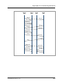
CIRCUIT TYPE
LOOP START
LINE
MODULE TYPE
FXO-4M
T1E1-2M
T1E1-4
II
FACILITY
INTERFACE CODE
NETWORK
JACK
02LS2
04DU9.DN
04DU9.1KN
04DU9.1SN
04DU9.1SN(PRI)
04DU9.DN
04DU9.1KN
04DU9.1SN
04DU9.1SN(PRI)
RJ11C
RJ48C
RJ48C
DID LINE
FXS-4M, FXS-24
T1E1-2M
T1E1-4
02RV2.T
04DU9.BN
04DU9.BN
RJ11C
RJ48C
RJ48C
E & M TIE LINE
E & M-2M
T1E1-2M
T1E1-4
TL11M
04DU9.BN
04DU9-BN
RJ45S
RJ48C
RJ48C
© SAMSUNG Electronics Co., Ltd.
Ubigate iBG series TroubleShooting Manual/Ed.00
Ringer Equivalence Number
The REN is used to determine the number of devices that may be connected to
a telephone line. Excessive RENs on a telephone line may result in the devices
not ringing in response to an incoming call. In most but not all areas, the sum
of RENs should not exceed five(5.0). To be certain of the number of devices
that may be connected to a line, as determined by the total RENs, contact the
local telephone company. For earlier products, the REN is separately shown
on the label.
Incidence of Harm
If this equipment causes harm to the telephone network, the telephone
company will notify you in advance that temporary discontinuance of service
may be required. But if advance notice isn’t practical, the telephone company
will notify the customer as soon as possible. Also, you will be advised of your
right to file a complaint with the FCC if you believe it is necessary.
Changes to Telephone Company Equipment or Facilities
The telephone company may make changes in its facilities, equipment,
operations or procedures that could affect the operation of the equipment.
If this happens the telephone company will provide advance notice in order for
you to make necessary modifications to maintain uninterrupted service.
Service Center
If trouble is experienced with the Ubigate iBG system, please contact your
local office of SAMSUNG ELECTRONICS, CO., LTD. for repair or warranty
information. If the trouble is causing harm to the telephone network, the
telephone company may request that you remove the equipment from the
network until the problem is resolved.
Field Repairs
Only technicians certified on the Ubigate iBG system, are authorized by
SAMSUNG ELECTRONICS, CO., LTD. to perform system repairs.
Certified technicians may replace modular parts of a system to repair or
diagnose trouble. Defective modular parts can be returned to SAMSUNG
ELECTRONICS, CO., LTD. for repair.
© SAMSUNG Electronics Co., Ltd.
III
GENERAL USER INFORMATION
General
Connection to party line service is subject to state tariffs. Contact the state
public utility commission, public service commission or corporation
commission for information.
Equipment with Direct Inward Dialing (‘DID’)
ALLOWING THIS EQUIPMENT TO BE OPERATED IN SUCH A
MANNER AS TO NOT PROVIDE FOR PROPER ANSWER
SUPERVISION IS A VIOLATION OF PART 68 OF THE FCC’S RULES
PROPER ANSWER SUPERVISION IS WHEN:
A)
B)
This equipment returns answer supervision to the Public Switched
Telephone Network(PSTN) when DID calls are:
y
Answered by the called station
y
Answered by the attendant
y
Routed to a recorded announcement that can be administered by the
Customer Premises Equipment(CPE) user.
y
Routed to a dial prompt
This equipment returns answer supervision on all DID calls forwarded to
the PSTN.
y
Permissible exceptions are:
y
A call is unanswered
y
A busy tone is received
y
A reorder tone is received
Equal Access Requirements
This equipment is capable of providing users access to interstate providers of
operator services through the use of access codes. Modification of this
equipment by call aggregators to block access dialing codes is a violation of
the Telephone Operator consumers Act of 1990.
IV
© SAMSUNG Electronics Co., Ltd.
Ubigate iBG series TroubleShooting Manual/Ed.00
Electrical Safety Advisory
Parties responsible for equipment requiring AC power should consider
including an advisory notice in their customer information suggesting the
customer use a surge arrestor. Telephone companies report that electrical
surges, typically lightning transients, are very destructive to customer terminal
equipment connected to AC power sources. This has been identified as a
major nationwide problem.
Music on Hold Warning
In accordance with US copyright laws, a license may be required from
the American Society of Composers, Authors and Publishers(ASCAP)
or other similar organizations if copyright music is transmitted through
the Music on Hold feature.
SAMSUNG ELECTRONICS, CO., LTD. hereby disclaims any liability
arising out of failure to obtain such a license.
DISA Warning
Lines that are used for the Direct Inward System Access feature must have the
disconnect supervision options provided by the telephone company.
As it is impossible to control who may access your DISA line it is
suggested that you do not turn this feature on unless you intend to
use it. If you do use this feature, it is good practice to frequently
change pass codes and periodically review your telephone records for
unauthorized use.
© SAMSUNG Electronics Co., Ltd.
V
GENERAL USER INFORMATION
Safety Warning
High touch current earth connection essential before making
telecommunication network connection.
Energy Hazard - careful treatment is needed.
Every wire for communication should be larger than 26 AWG.
Double pole/neutral fusing.
Underwriters Laboratories
The system has been tested to comply with safety standards in the United
States and Canada. This system is listed with Underwriters Laboratories.
The cUL Mark is separately shown on the label.
The following statement from Underwriters Labs applies to the Ubigate System:
1.
2.
VI
Separation of TNV and SELV - Pluggable A: ‘The separate protective
earthing terminal provided on this product shall be permanently
connected to earth.’(Instruction)
Separation of TNV and SELV - Pluggable B: ‘Disconnect TNV circuit
connector(s) before disconnecting power.’(Instruction)
© SAMSUNG Electronics Co., Ltd.
Ubigate iBG series TroubleShooting Manual/Ed.00
3.
4.
5.
6.
Warning to service personnel: ‘CAUTION: Double pole/neutral fusing’
Telephone line cord: ‘CAUTION: To reduce the risk of fire, use only No.
26 AWG or larger(e.g., 24 AWG) UL Listed or CSA Certified
Telecommunication Line Cord’
Leakage currents due to ringing voltage - Earthing installation
instructions: ‘1. A supplementary equipment earthing conductor is to be
installed between the product or system and earth, that is, in addition to
the equipment earthing conductor in the power supply cord. 2. The
supplementary equipment earthing conductor may not be smaller in size
than the unearthed branch-circuit supply conductors. The equipment
earthing conductor is to be connected to the product at the terminal
provided, and connected to earth in a manner that ill retain the earth
connection when the power supply cord is unplugged. The connection to
earth of the supplementary earthing conductor shall be in compliance
with the appropriate rules for terminating bonding jumpers in Part K of
Article 250 of the National Electrical Code, ANSI/NFPA 70 and Article
10 of Part 1 of the Canadian Electrical Code, Part 1, C22.1. Termination
of the supplementary earthing conductor is permitted to be made to
building steel, to a metal electrical raceway system, or to any earthed
item that is permanently and reliably connected to the electrical service
equipment earthed. 3. Bare, covered, or insulated earthing conductors are
acceptable.
A covered or insulated conductor must have a continuous outer finish
that is either green, or green with one or more yellow stripes.’
Safety Instructions - Rack Mount ‘Rack Mount Instructions The following or similar rack-mount instructions are included with the
installation instructions:
A) Elevated Operating Ambient - If installed in a closed or multi-unitrack
assembly, the operating ambient temperature of the rack environment
may be greater than room ambient. Therefore, consideration should be
given to installing the equipment in an environment compatible with
the maximum ambient temperature(Tma) specified by the
manufacturer.
© SAMSUNG Electronics Co., Ltd.
VII
GENERAL USER INFORMATION
B) Reduced Air Flow - Installation of the equipment in a rack should be
such that the amount of air flow required for safe operation of the
equipment is not compromised.
C) Mechanical Loading - Mounting of the equipment in the rack should be
such that a hazardous condition is not achieved due to uneven
mechanical loading.
D) Circuit Overloading - Consideration should be given to the connection
of the equipment to the supply circuit and the effect that overloading of
the circuits might have on overcurrent protection and supply wiring.
Appropriate consideration of equipment nameplate ratings should be
used when addressing this concern.
E)
VIII
Reliable Earthing - Reliable earthing of rack-mounted equipment
should be maintained. Particular attention should be given to supply
connections other than direct connections to the branch circuit(e.g.,
use of power strips).’
© SAMSUNG Electronics Co., Ltd.
Ubigate iBG series TroubleShooting Manual
INTRODUCTION
Purpose
Ubigate iBG Trouble Shooting Manual describes the troubleshooting
procedures for the faults that can occur on iBG system.
Conventions
The following types of paragraphs contain special information that must be
carefully read and thoroughly understood. Such information may or may not
be enclosed in a rectangular box, separating it from the main text, but is
always preceded by an icon and/or a bold title.
NOTE
Indicates additional information as a reference.
Console Screen Output
y
The lined box with ‘Courier New’ font will be used to distinguish
between the main content and console output screen text.
y
‘Bold Courier New’ font will indicate the value entered by the
operator on the console screen.
© SAMSUNG Electronics Co., Ltd.
IX
INTRODUCTION
Contacting Technical Support
For questions regarding the product and the content of this document
Please visit:
http://www.samsungnetwork.com
Obtaining Publications and Additional Information
The Ubigate iBG system documentation set, and additional literature is
available at:
http://www.samsungnetwork.com
Revision History
X
EDITION
DATE OF ISSUE
REMARKS
00
09. 2007.
First draft
© SAMSUNG Electronics Co., Ltd.
Ubigate iBG series TroubleShooting Manual
TABLE OF CONTENTS
GENERAL USER INFORMATION
I
Radio Frequency Interference ........................................................................................ I
FCC Requirements ......................................................................................................... I
Music on Hold Warning..................................................................................................V
DISA Warning ................................................................................................................V
Safety Warning .............................................................................................................VI
Underwriters Laboratories ............................................................................................VI
INTRODUCTION
IX
Purpose ........................................................................................................................IX
Conventions..................................................................................................................IX
Console Screen Output ................................................................................................IX
Contacting Technical Support ........................................................................................X
Obtaining Publications and Additional Information.........................................................X
Revision History.............................................................................................................X
CHAPTER 1. SYSTEM and Management
1-1
SNMP Agent is not responding ...................................................................................... 1-1
Symptoms................................................................................................................... 1-1
Possible Causes......................................................................................................... 1-1
Troubleshooting .......................................................................................................... 1-1
Users cannot log in using TACACS+ ............................................................................. 1-2
Symptoms................................................................................................................... 1-2
Possible Causes......................................................................................................... 1-2
Troubleshooting .......................................................................................................... 1-2
Users cannot log in using RADIUS ................................................................................ 1-4
Symptoms................................................................................................................... 1-4
Possible Causes......................................................................................................... 1-4
Troubleshooting .......................................................................................................... 1-4
© SAMSUNG Electronics Co., Ltd.
XI
TABLE OF CONTENTS
User is locked out on authentication failure .................................................................1-6
Symptoms...................................................................................................................1-6
Possible Causes .........................................................................................................1-6
Troubleshooting ..........................................................................................................1-6
DHCP IP address may be in use alarm ..........................................................................1-7
Symptoms...................................................................................................................1-7
Possible Causes .........................................................................................................1-7
Troubleshooting ..........................................................................................................1-7
DHCP subnet mismatch alarm........................................................................................1-8
Symptoms...................................................................................................................1-8
Possible Causes .........................................................................................................1-8
Troubleshooting ..........................................................................................................1-8
DHCPv6 relay wrong interface alarm .............................................................................1-9
Symptoms...................................................................................................................1-9
Possible Causes .........................................................................................................1-9
Troubleshooting ..........................................................................................................1-9
DHCPv6 relay forwarding fail........................................................................................1-10
Symptoms.................................................................................................................1-10
Possible Causes .......................................................................................................1-10
Troubleshooting ........................................................................................................1-10
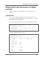
DHCPv6 unable to configure domain name ................................................................ 1-11
Symptoms................................................................................................................. 1-11
Possible Causes ....................................................................................................... 1-11
Troubleshooting ........................................................................................................ 1-11
Time synchronization with SNTP server fails .............................................................1-12
Symptoms.................................................................................................................1-12
Possible Causes .......................................................................................................1-12
Troubleshooting ........................................................................................................1-12
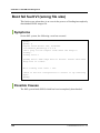
Getting file list using Windows FTP clients fails.........................................................1-13
Symptoms.................................................................................................................1-13
Possible Causes .......................................................................................................1-13
Troubleshooting ........................................................................................................1-13
Boot fail fault I (wrong SNOS).......................................................................................1-15
Symptoms.................................................................................................................1-15
Possible Causes .......................................................................................................1-15
Troubleshooting ........................................................................................................1-15
XII
© SAMSUNG Electronics Co., Ltd.
Ubigate iBG series TroubleShooting Manual/Ed.00
Boot fail fault II (ascii mode file)................................................................................... 1-16
Symptoms................................................................................................................. 1-16
Possible Causes....................................................................................................... 1-16
Troubleshooting ........................................................................................................ 1-16
Boot fail fault III (non-existing file in cf0) .................................................................... 1-17
Symptoms................................................................................................................. 1-17
Possible Causes....................................................................................................... 1-17
Troubleshooting ........................................................................................................ 1-17
Boot fail fault IV (wrong model SNOS) ........................................................................ 1-18
Symptoms................................................................................................................. 1-18
Possible Causes....................................................................................................... 1-18
Troubleshooting ........................................................................................................ 1-18
Boot fail fault V (no access right ftp file/non-existing in ftp server) ......................... 1-19
Symptoms................................................................................................................. 1-19
Possible Causes....................................................................................................... 1-19
Troubleshooting ........................................................................................................ 1-19
Boot fail fault VI (wrong file size) ................................................................................. 1-20
Symptoms................................................................................................................. 1-20
Possible Causes....................................................................................................... 1-20
Troubleshooting ........................................................................................................ 1-21
Boot fail fault VII (wrong checksum)............................................................................ 1-22
Symptoms................................................................................................................. 1-22
Possible Causes....................................................................................................... 1-22
Troubleshooting ........................................................................................................ 1-22
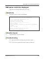
ISM status cannot be displayed ................................................................................... 1-23
Symptoms................................................................................................................. 1-23
Possible Causes....................................................................................................... 1-23
Troubleshooting ........................................................................................................ 1-23
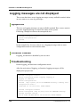
Logging messages are not displayed.......................................................................... 1-24
Symptoms................................................................................................................. 1-24
Possible Causes....................................................................................................... 1-24
Troubleshooting ........................................................................................................ 1-24
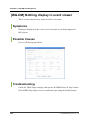
[iBG-DM]iBG-DM Download Fail................................................................................... 1-25
Symptoms................................................................................................................. 1-25
Possible Causes....................................................................................................... 1-25
Troubleshooting ........................................................................................................ 1-25
© SAMSUNG Electronics Co., Ltd.
XIII
TABLE OF CONTENTS
[iBG-DM] iBG-DM Web Connection Fail.......................................................................1-26
Symptoms.................................................................................................................1-26
Possible Causes .......................................................................................................1-26
Troubleshooting ........................................................................................................1-26
[iBG-DM] iBG-DM does not execute.............................................................................1-27
Symptoms.................................................................................................................1-27
Possible Causes .......................................................................................................1-27
Troubleshooting ........................................................................................................1-27
[iBG-DM] iBG-DM can’t connect with secure mode....................................................1-28
Symptoms.................................................................................................................1-28
Possible Causes .......................................................................................................1-28
Troubleshooting ........................................................................................................1-28
[iBG-DM] iBG-DM can’t login ........................................................................................1-29
Symptoms.................................................................................................................1-29
Possible Causes .......................................................................................................1-29
Troubleshooting ........................................................................................................1-29
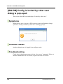
[iBG-DM] Config is locked by other user dialog is pop-uped ....................................1-30
Symptoms.................................................................................................................1-30
Possible Causes .......................................................................................................1-30
Troubleshooting ........................................................................................................1-30
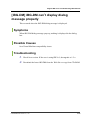
[iBG-DM] iBG-DM can’t display dialog message properly .........................................1-31
Symptoms.................................................................................................................1-31
Possible Causes .......................................................................................................1-31
Troubleshooting ........................................................................................................1-31
[iBG-DM] CLI display result is not matched with iBG-DM screen display ................1-32
Symptoms.................................................................................................................1-32
Possible Causes .......................................................................................................1-32
Troubleshooting ........................................................................................................1-32
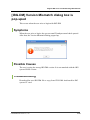
[iBG-DM] Version Mismatch dialog box is pop-uped..................................................1-33
Symptoms.................................................................................................................1-33
Possible Causes .......................................................................................................1-33
Troubleshooting ........................................................................................................1-33
[iBG-DM] Community Setting dialog box pop-uped ...................................................1-34
Symptoms.................................................................................................................1-34
Possible Causes .......................................................................................................1-34
Troubleshooting ........................................................................................................1-34
XIV
© SAMSUNG Electronics Co., Ltd.
Ubigate iBG series TroubleShooting Manual/Ed.00
[iBG-DM] ISM Bind Address is wrong dialog box is pop-uped.................................. 1-35
Symptoms................................................................................................................. 1-35
Possible Causes....................................................................................................... 1-35
Troubleshooting ........................................................................................................ 1-35
[iBG-DM] Nothing display in event viewer .................................................................. 1-36
Symptoms................................................................................................................. 1-36
Possible Causes....................................................................................................... 1-36
Troubleshooting ........................................................................................................ 1-36
[iBG-DM] SNMP Get Error occurred during performance monitoring ...................... 1-37
Symptoms................................................................................................................. 1-37
Possible Causes....................................................................................................... 1-37
Troubleshooting ........................................................................................................ 1-37
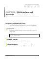
CHAPTER 2. WAN Interface and Protocols
2-1
Detection of T1 RAIS alarm ............................................................................................ 2-1
Symptoms................................................................................................................... 2-1
Possible Causes......................................................................................................... 2-1
Troubleshooting .......................................................................................................... 2-1
All T1’s RLOF alarm raised ............................................................................................. 2-2
Symptoms................................................................................................................... 2-2
Possible Causes......................................................................................................... 2-3
Troubleshooting .......................................................................................................... 2-3
ppp negotiation failed ..................................................................................................... 2-4
Symptoms................................................................................................................... 2-4
Possible Causes......................................................................................................... 2-4
Troubleshooting .......................................................................................................... 2-4
ipcp not in open state ..................................................................................................... 2-5
Symptoms................................................................................................................... 2-5
Possible Causes......................................................................................................... 2-5
Troubleshooting .......................................................................................................... 2-5
PPP Authentication fail ................................................................................................... 2-6
Symptoms................................................................................................................... 2-6
Possible Causes......................................................................................................... 2-6
Troubleshooting .......................................................................................................... 2-6
© SAMSUNG Electronics Co., Ltd.
XV
TABLE OF CONTENTS
CHAPTER 3. Switching and Routing Protocols
3-1
Fail to make Ethernet interface.......................................................................................3-1
Symptoms...................................................................................................................3-1
Possible Causes .........................................................................................................3-1
Troubleshooting ..........................................................................................................3-2
Fail to configure mirror ...................................................................................................3-2
Symptoms...................................................................................................................3-2
Possible Causes .........................................................................................................3-3
Troubleshooting ..........................................................................................................3-3
Error message for poe ....................................................................................................3-4
Symptoms...................................................................................................................3-4
Possible Causes .........................................................................................................3-4
Troubleshooting ..........................................................................................................3-5
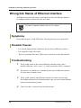
Wrong link Status of Ethernet interface.........................................................................3-6
Symptoms...................................................................................................................3-6
Possible Causes .........................................................................................................3-6
Troubleshooting ..........................................................................................................3-6
Error message during configuring switchport on Ethernet interface .........................3-7
Symptoms...................................................................................................................3-7
Possible Causes .........................................................................................................3-7
Troubleshooting ..........................................................................................................3-7
GRE (IPIP) tunnel interface down...................................................................................3-8
Symptoms...................................................................................................................3-8
Possible Causes .........................................................................................................3-8
Troubleshooting ..........................................................................................................3-8
No BGP Adjacency (iBGP) ..............................................................................................3-9
Symptoms...................................................................................................................3-9
Possible Causes .........................................................................................................3-9
Troubleshooting ..........................................................................................................3-9
No BGP Adjacency (eBGP) ...........................................................................................3-10
Symptoms.................................................................................................................3-10
Possible Causes .......................................................................................................3-10
Troubleshooting ........................................................................................................3-10
No BGP4+ Adjacency (iBGP) ........................................................................................ 3-11
Symptoms................................................................................................................. 3-11
Possible Causes ....................................................................................................... 3-11
XVI
© SAMSUNG Electronics Co., Ltd.
Ubigate iBG series TroubleShooting Manual/Ed.00
Troubleshooting ........................................................................................................ 3-11
No BGP4+ Adjacency (eBGP) ....................................................................................... 3-12
Symptoms................................................................................................................. 3-12
Possible Causes....................................................................................................... 3-12
Troubleshooting ........................................................................................................ 3-12
No PIM-SM Adjacency ................................................................................................... 3-13
Symptoms................................................................................................................. 3-13
Possible Causes....................................................................................................... 3-13
Troubleshooting ........................................................................................................ 3-13
No PIM-SM BSR and RP information ........................................................................... 3-14
Symptoms................................................................................................................. 3-14
Possible Causes....................................................................................................... 3-14
Troubleshooting ........................................................................................................ 3-14
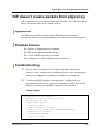
RIP doesn’t receive packets from adjacency .............................................................. 3-15
Symptoms................................................................................................................. 3-15
Possible Causes....................................................................................................... 3-15
Troubleshooting ........................................................................................................ 3-15
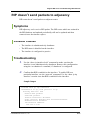
RIP doesn’t send packets to adjacency....................................................................... 3-17
Symptoms................................................................................................................. 3-17
Possible Causes....................................................................................................... 3-17
Troubleshooting ........................................................................................................ 3-17
IGMP has no group membership. ................................................................................ 3-19
Symptoms................................................................................................................. 3-19
Possible Causes....................................................................................................... 3-19
Troubleshooting ........................................................................................................ 3-19
RIPng has no adjacency ............................................................................................... 3-21
Symptoms................................................................................................................. 3-21
Possible Causes....................................................................................................... 3-21
Troubleshooting ........................................................................................................ 3-21
No OSPFv2 Adjacency .................................................................................................. 3-23
Symptoms................................................................................................................. 3-23
Possible Causes....................................................................................................... 3-23
Troubleshooting ........................................................................................................ 3-23
No OSPFv3 Adjacency .................................................................................................. 3-29
Symptoms................................................................................................................. 3-29
Possible Causes....................................................................................................... 3-29
Troubleshooting ........................................................................................................ 3-29
© SAMSUNG Electronics Co., Ltd.
XVII
TABLE OF CONTENTS
No DVMRP Adjacency ...................................................................................................3-34
Symptoms.................................................................................................................3-34
Possible Causes .......................................................................................................3-34
Troubleshooting ........................................................................................................3-34
Incorrect VRRP Status...................................................................................................3-35
Symptoms.................................................................................................................3-35
Possible Causes .......................................................................................................3-35
Troubleshooting ........................................................................................................3-36
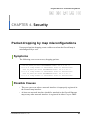
CHAPTER 4. Security
4-1
Packet dropping by map misconfigurations .................................................................4-1
Symptoms...................................................................................................................4-1
Possible Causes .........................................................................................................4-1
Troubleshooting ..........................................................................................................4-2
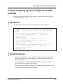
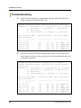
Packet dropping by misconfigured firewall policies ....................................................4-3
Symptoms...................................................................................................................4-3
Possible Causes .........................................................................................................4-3
Troubleshooting ..........................................................................................................4-4
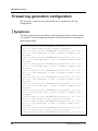
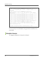
Firewall log generation configuration............................................................................4-6
Symptoms...................................................................................................................4-6
Possible Causes .........................................................................................................4-8
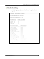
Troubleshooting ..........................................................................................................4-9
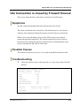
Idle Connection is closed by Firewall Timeout ........................................................... 4-11
Symptoms................................................................................................................. 4-11
Possible Causes ....................................................................................................... 4-11
Troubleshooting ........................................................................................................ 4-11
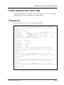
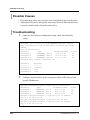
Traffic between the same map......................................................................................4-13
Symptoms.................................................................................................................4-13
Possible Causes .......................................................................................................4-14
Troubleshooting ........................................................................................................4-14
VPN SAs creation fail ....................................................................................................4-16
Symptoms.................................................................................................................4-16
Possible Causes .......................................................................................................4-16
Troubleshooting ........................................................................................................4-16
CA Certification import fail ...........................................................................................4-17
Symptoms.................................................................................................................4-17
Possible Causes .......................................................................................................4-17
XVIII
© SAMSUNG Electronics Co., Ltd.
Ubigate iBG series TroubleShooting Manual/Ed.00
Troubleshooting ........................................................................................................ 4-17
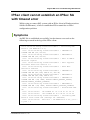
IPSec client cannot establish an IKE SA with NO_PROPOSAL_CHOSEN error ...... 4-18
Symptoms................................................................................................................. 4-18
Possible Causes....................................................................................................... 4-18
Troubleshooting ........................................................................................................ 4-18
IPSec client cannot establish an IPSec SA with timeout error .................................. 4-19
Symptoms................................................................................................................. 4-19
Possible Causes....................................................................................................... 4-20
Troubleshooting ........................................................................................................ 4-20
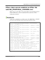
IPSec client cannot establish an IPSec SA with NO_PROPOSAL_CHOSEN error .. 4-21
Symptoms................................................................................................................. 4-21
Possible Causes....................................................................................................... 4-22
Troubleshooting ........................................................................................................ 4-22
IPSec client cannot connect a server over an IPSec tunnel ...................................... 4-23
Symptoms................................................................................................................. 4-23
Possible Causes....................................................................................................... 4-23
Troubleshooting ........................................................................................................ 4-23
IPSec client cannot establish an IPSec tunnel with user authentication timeout.... 4-24
Symptoms................................................................................................................. 4-24
Possible Causes....................................................................................................... 4-25
Troubleshooting ........................................................................................................ 4-26
IPSec client cannot establish an IPSec tunnel with user authentication failure...... 4-27
Symptoms................................................................................................................. 4-27
Possible Causes....................................................................................................... 4-28
Troubleshooting ........................................................................................................ 4-28
CHAPTER 5. VOICE
5-1
Max call limit alarm.......................................................................................................... 5-1
Symptoms................................................................................................................... 5-1
Possible Causes......................................................................................................... 5-1
Troubleshooting .......................................................................................................... 5-2
Max DSP limit alarm ........................................................................................................ 5-3
Symptoms................................................................................................................... 5-3
Possible Causes......................................................................................................... 5-3
Troubleshooting .......................................................................................................... 5-3
SIP entity connection fail alarm ..................................................................................... 5-5
Symptoms................................................................................................................... 5-5
© SAMSUNG Electronics Co., Ltd.
XIX
TABLE OF CONTENTS
Possible Causes .........................................................................................................5-5
Troubleshooting ..........................................................................................................5-5
Gatekeeper connection fail alarm ..................................................................................5-6
Symptoms...................................................................................................................5-6
Possible Causes .........................................................................................................5-6
Troubleshooting ..........................................................................................................5-6
H.323 trunk call trouble ...................................................................................................5-7
Symptoms...................................................................................................................5-7
Possible Causes .........................................................................................................5-7
Troubleshooting ..........................................................................................................5-7
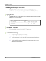
H.323 gatekeeper trouble ................................................................................................5-8
Symptoms...................................................................................................................5-8
Possible Causes .........................................................................................................5-8
Troubleshooting ..........................................................................................................5-8
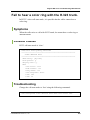
Fail to hear a color ring with the H.323 trunk. ...............................................................5-9
Symptoms...................................................................................................................5-9
Possible Causes .........................................................................................................5-9
Troubleshooting ..........................................................................................................5-9
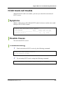
FXO connect alarm ........................................................................................................5-10
Symptoms.................................................................................................................5-10
Possible Causes .......................................................................................................5-10
Troubleshooting ........................................................................................................5-10
FXO voice quality tunning ............................................................................................ 5-11
Symptoms................................................................................................................. 5-11
Possible Causes ....................................................................................................... 5-11
Troubleshooting ........................................................................................................ 5-11
FXO Caller-ID detection.................................................................................................5-12
Symptoms.................................................................................................................5-12
Possible Causes .......................................................................................................5-12
Troubleshooting ........................................................................................................5-12
FXO Ground-Start outbound call failures ....................................................................5-13
Symptoms.................................................................................................................5-13
Possible Causes .......................................................................................................5-13
Troubleshooting ........................................................................................................5-13
FXS port Line-Lockout ..................................................................................................5-14
Symptoms.................................................................................................................5-14
Possible Causes .......................................................................................................5-14
XX
© SAMSUNG Electronics Co., Ltd.
Ubigate iBG series TroubleShooting Manual/Ed.00
Troubleshooting ........................................................................................................ 5-14
SIP-UA cannot register to the SIP server .................................................................... 5-15
Symptoms................................................................................................................. 5-15
Possible Causes....................................................................................................... 5-16
Troubleshooting ........................................................................................................ 5-16
SIP-UA cannot register to Ubigate iPX ........................................................................ 5-17
Symptoms................................................................................................................. 5-17
Possible Causes....................................................................................................... 5-18
Troubleshooting ........................................................................................................ 5-18
Outbound SIP Calls fail because of CODEC mismatch.............................................. 5-19
Symptoms................................................................................................................. 5-19
Possible Causes....................................................................................................... 5-20
Troubleshooting ........................................................................................................ 5-20
Outbound SIP Calls fail because of Restriction.......................................................... 5-21
Symptoms................................................................................................................. 5-21
Possible Causes....................................................................................................... 5-21
Troubleshooting ........................................................................................................ 5-21
SIP phone Registration to Ubigate iBG system fails.................................................. 5-22
Symptoms................................................................................................................. 5-22
Possible Causes....................................................................................................... 5-22
Troubleshooting ........................................................................................................ 5-23
Each SIP message uses different transport protocol ................................................ 5-24
Symptoms................................................................................................................. 5-24
Possible Causes....................................................................................................... 5-24
Troubleshooting ........................................................................................................ 5-25
ISDN voice-port down ................................................................................................... 5-27
Symptoms................................................................................................................. 5-27
Possible Causes....................................................................................................... 5-27
Troubleshooting ........................................................................................................ 5-28
ISDN trunk post-dial delay problem (PDD) .................................................................. 5-34
Symptoms................................................................................................................. 5-34
Possible Causes....................................................................................................... 5-34
Troubleshooting ........................................................................................................ 5-34
ISDN incoming call failure ............................................................................................ 5-36
Symptoms................................................................................................................. 5-36
Possible Causes....................................................................................................... 5-36
Troubleshooting ........................................................................................................ 5-36
© SAMSUNG Electronics Co., Ltd.
XXI
TABLE OF CONTENTS
ISDN interface down......................................................................................................5-38
Symptoms.................................................................................................................5-38
Possible Causes .......................................................................................................5-38
Troubleshooting ........................................................................................................5-38
No Busy Tone and No Annoucement Message on ISDN-SIP/H.323...........................5-45
Symptoms.................................................................................................................5-45
Possible Causes .......................................................................................................5-45
Troubleshooting ........................................................................................................5-46
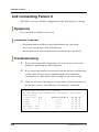
Call connecting Failure I ...............................................................................................5-48
Symptoms.................................................................................................................5-48
Possible Causes .......................................................................................................5-48
Troubleshooting ........................................................................................................5-48
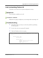
Call connecting Failure II ..............................................................................................5-50
Symptoms.................................................................................................................5-50
Possible Causes .......................................................................................................5-50
Troubleshooting ........................................................................................................5-50
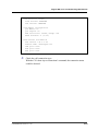
Call connecting Failure III .............................................................................................5-51
Symptoms.................................................................................................................5-51
Possible Causes .......................................................................................................5-51
Troubleshooting ........................................................................................................5-51
TLS connection fault .....................................................................................................5-52
Symptoms.................................................................................................................5-52
Possible Causes .......................................................................................................5-52
Troubleshooting ........................................................................................................5-52
Digit Manipulation Failure.............................................................................................5-54
Symptoms.................................................................................................................5-54
Possible Causes .......................................................................................................5-54
Troubleshooting ........................................................................................................5-54
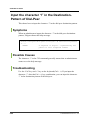
Input the character ‘?’ in the Destination-Pattern of Dial-Peer ..................................5-56
Symptoms.................................................................................................................5-56
Possible Causes .......................................................................................................5-56
Troubleshooting ........................................................................................................5-56
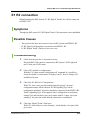
E1 R2 connection...........................................................................................................5-57
Symptoms.................................................................................................................5-57
Possible Causes .......................................................................................................5-57
Troubleshooting ........................................................................................................5-57
XXII
© SAMSUNG Electronics Co., Ltd.
Ubigate iBG series TroubleShooting Manual/Ed.00
E1 R2 CAS Custom........................................................................................................ 5-58
Symptoms................................................................................................................. 5-58
Possible Causes....................................................................................................... 5-58
Troubleshooting ........................................................................................................ 5-58
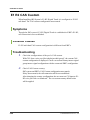
T1 CAS connection........................................................................................................ 5-59
Symptoms................................................................................................................. 5-59
Possible Causes....................................................................................................... 5-59
Troubleshooting ........................................................................................................ 5-59
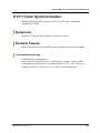
E1/T1 Clock Synchronization ....................................................................................... 5-61
Symptoms................................................................................................................. 5-61
Possible Causes....................................................................................................... 5-61
Troubleshooting ........................................................................................................ 5-61
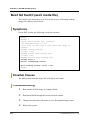
DSP fail fault .................................................................................................................. 5-62
Symptoms................................................................................................................. 5-62
Possible Causes....................................................................................................... 5-62
Troubleshooting ........................................................................................................ 5-62
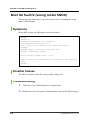
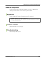
DSP No response .......................................................................................................... 5-63
Symptoms................................................................................................................. 5-63
Possible Causes....................................................................................................... 5-63
Troubleshooting ........................................................................................................ 5-63
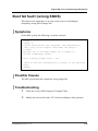
DSP packet loss............................................................................................................. 5-64
Symptoms................................................................................................................. 5-64
Possible Causes....................................................................................................... 5-64
Troubleshooting ........................................................................................................ 5-64
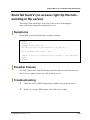
DSP voice quality tunning ............................................................................................ 5-65
Symptoms................................................................................................................. 5-65
Possible Causes....................................................................................................... 5-65
Troubleshooting ........................................................................................................ 5-65
© SAMSUNG Electronics Co., Ltd.
XXIII
TABLE OF CONTENTS
This page is intentionally left blank.
XXIV
© SAMSUNG Electronics Co., Ltd.
Ubigate iBG series TroubleShooting Manual
CHAPTER 1. SYSTEM and Management
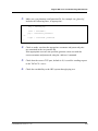
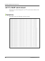
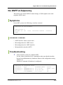
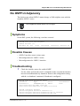
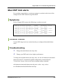
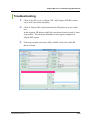
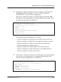
SNMP Agent is not responding
When an SNMP manager application is trying to receive a response from the
SNMP Agent on iBG system, the Agent does not respond.
Symptoms
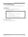
The SNMP manager application sends a request for any managed object, the
agent is not responding and the message shows timeout.
net-snmp-5.2/apps>$ snmpget -v2c -c samsung
90.1.1.4 .1.3.6.1.2.1.1.2.0
Timeout: No Response from 90.1.1.4.
Possible Causes
y
The SNMP manager application is not reachable from the iBG system.
y
The SNMP community string does not match.
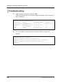
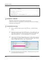
Troubleshooting
1.
2.
3.
Check that the correct UDP port in your SNMP manager application, 161,
is used for sending the requests.
Check the reachabilty to the iBG system through ping test.
When the UDP port and ping test are ok, check the community strings
configured in your SNMP manager application.
© SAMSUNG Electronics Co., Ltd.
1-1
CHAPTER 1. SYSTEM and Management
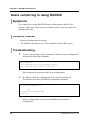
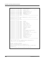
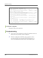
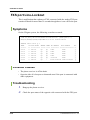
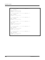
Users cannot log in using TACACS+
Symptoms
User cannot log in using TACACS+(Terminal Access Controller Access
Control System+). Either user cannot get the username prompt or get the
prompt but authentication or authorization fails.
Possible Causes
y
Required configuration is missing.
y
Username and password are not in the /etc/passwd file on the TACACS+
server.
y
The TACACS+ daemon(server) is not reachable from the iBG system.
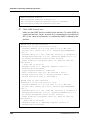
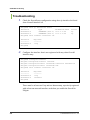
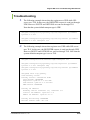
Troubleshooting
1.
Use the ‘show runing-config’ command to make sure your configuration
includes the following commands:
aaa
aaa
aaa
aaa
enable
authentication login TACACS tacacs
authentication protocols ETC ascii/pap
authorization commands TACACS tacacs
If the command is not present, add it to the configuration.
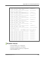
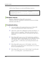
2.
In addition, check the configuration of the interface being used.
The interface must have the following commands configured:
interface ethernet 0/4
…
aaa
authentication TACACS ETC
authorization TACACS
exit aaa
If these configurations are not present, add them to the interface
configuration.
1-2
© SAMSUNG Electronics Co., Ltd.
Ubigate iBG series TroubleShooting Manual/Ed.00
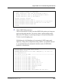
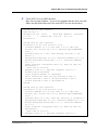
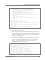
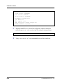
3.
Make sure your daemon configuration file, for example ‘tac_plus.cfg’,
includes the following lines, as appropriate:
key = shared_key
…
user = username {
pap = cleartext password
or
login = cleartext password
}
4.
5.
6.
Check to make sure that the appropriate username and password pairs
are contained in the /etc/passwd file.
If the appropriate users are not specified, generate a new user with the
correct username and password, using the ‘add user’ command.
Check that the correct TCP port, default is 49, is used for sending request
to the TACACS+ server.
Check the reachability to the iBG system through ping test.
© SAMSUNG Electronics Co., Ltd.
1-3
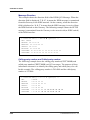
CHAPTER 1. SYSTEM and Management
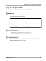
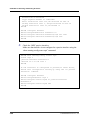
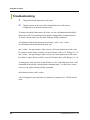
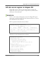
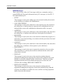
Users cannot log in using RADIUS
Symptoms
User cannot log in using RADIUS(Remote Authentication Dial-In User
Service). Either user cannot get the username prompt or get the prompt but
authentication fails.
Possible Causes
y
Required configuration is missing.
y
The RADIUS daemon(server) is not reachable from the iBG system.
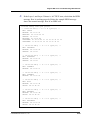
Troubleshooting
1.
Use the ‘show runing-config’ command to make sure your configuration
includes the following commands:
aaa enable
aaa authentication login RADIUS radius
aaa authentication protocols PAP pap
If the command is not present, add it to the configuration.
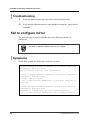
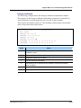
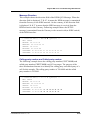
2.
In addition, check the configuration of the interface being used.
The interface must have the following commands configured:
interface ethernet 0/0
…
aaa
authentication RADIUS PAP
exit aaa
If these configurations are not present, add them to the interface
configuration.
1-4
© SAMSUNG Electronics Co., Ltd.
Ubigate iBG series TroubleShooting Manual/Ed.00
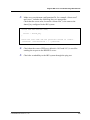
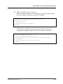
3.
Make sure your daemon configuration file, for example ‘clients.conf’
and ‘users’, includes the following lines, as appropriate:
Check that the secret value, located in ‘clients.conf’, is the same as the
shared_key configured in the iBG system:
client xxx.xxx.xxx.xxx /xxx{
…
secret = shared_key
}
Check the user name and the password located in ‘users’.
‘username’ User-Password = = ‘ password’
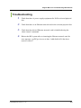
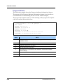
4.
5.
Check that the correct UDP port, default is 1812 and 1813, is used for
sending the request to the RADIUS server.
Check the reachability to the iBG system through the ping test.
© SAMSUNG Electronics Co., Ltd.
1-5
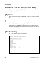
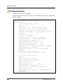
CHAPTER 1. SYSTEM and Management
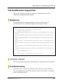
User is locked out on authentication failure
If the user-lock function is enabled and a user fails three times successively on
authentication while trying to access to the iBG system with telnet or ssh, then
the user will be locked out. The locked user cannot access the iBG system
remotely. Only the console is available for that user without unlocking the
account by an administrator.
Symptoms
On the iBG system, the following system log message occurs for the telnet user.
*Apr 28,2007,19:45:27 #AAA-notification: User aaa is locked
out on authentication failure from 90.90.90.240.
On the iBG system, the following system log message occurs for the ssh user.
*Apr 28,2007,19:42:50 #SSH-warning: SSHD: Too many
authentication failures for 'abc'
*Apr 28,2007,19:42:50 #SSH-warning: SSHD: User abc is locked
out on authentication failure.
Possible Causes
y
User forgot the password.
y
An attacker tried to access the system.
Troubleshooting
1.
1-6
Connect to the console if the locked user is the only administrator in the
system. The remote connection with telnet or ssh is also available if you
can use another administrator account.
2.
Verify that the user is locked out using ‘show user_accounts’ command.
3.
Unlock the user using ‘no user-lock username <user-id>‘ command.
© SAMSUNG Electronics Co., Ltd.
Ubigate iBG series TroubleShooting Manual/Ed.00
DHCP IP address may be in use alarm
This is an alarm created when the IP address for host binding may be in use by
another host. When the fault occurs DHCP server cannot allocate this IP
address to the configured host.
Symptoms
On the iBG system, the following event occurred.
May 28,2007,14:34:08 #DHCP-notification: IP address for host
binding may be in use(cid=[cid])
Possible Causes
The IP address for host binding is used by another host.
Troubleshooting
Reconfigure the IP address for host binding in the pool using the ‘host’
command.
© SAMSUNG Electronics Co., Ltd.
1-7
CHAPTER 1. SYSTEM and Management
DHCP subnet mismatch alarm
Alarm created when the subnet address of host binding does not match with
the subnet address of the interface. When this fault occurs the DHCP server
cannot allocate this IP address to the configured host.
Symptoms
On the iBG system, the following event occurred.
May 28,2007,14:34:08 #DHCP-notification: Subnet mismatch for
host binding(cid=[cid])
Possible Causes
The Subnet address of the host binding does not match the subnet address of
the interface.
Troubleshooting
1.
2.
1-8
Check the IP address for host binding in the pool using the ‘show ip dhcp
config’ command.
Check the subnet mask for host binding in the pool using the ‘show ip
dhcp config’ command..
© SAMSUNG Electronics Co., Ltd.
Ubigate iBG series TroubleShooting Manual/Ed.00
DHCPv6 relay wrong interface alarm
Alarm to notify whether the relay interface is valid or not in case the relay
server address is linked to local address.
This alarm is applied to SNOS version 2.0.0 or higher.
Symptoms
On the iBG system, the following event has occurred.
May 28,2007,14:34:08 #DHCPv6-warning: DHCPv6 Relay: trying
to send on wrong interface([name])
May 28,2007,14:34:08 #DHCPv6-warning: DHCPv6 Relay: Trying
to configure wrong interface ([name])
May 28,2007,14:34:08 #DHCPv6-warning: Not able to get server
itf index for interface name ([name])
Possible Causes
y
The configuring interface does not exist.
y
The configuring interface is not configured to enable IPv6.
Troubleshooting
1.
Verify that the configuring interface name is correct.
2.
Check that the configuring interface is enabled for IPv6 configuration.
© SAMSUNG Electronics Co., Ltd.
1-9
CHAPTER 1. SYSTEM and Management
DHCPv6 relay forwarding fail
Alarm to notify that relay message forwarding has failed. When the fault
occurs the DHCPv6 client cannot be allocated to IPv6 prefix through this
DHCPv6 relay agent.
This alarm is applied to SNOS version 2.0.0 or higher.
Symptoms
On the iBG system, the following event has occurred.
INFO [DHCP_V6] dhcp6s.c:1604: received SOLICIT from
fe80::200:11ff:fe7c:5637
ERR [DHCP_V6] dhcp6relay.c:1125:
dhcp6r_modify_global_prefix_based_on_ifp failed to overwrite
the linkaddr.
Possible Causes
y
The configuring interface is not configured to enable IPv6.
y
The configuring interface is not configured for IPv6 global address.
Troubleshooting
1-10
1.
Check that the configuring interface is enabled for IPv6 configuration.
2.
Check that the configuring interface is set for IPv6 global address.
© SAMSUNG Electronics Co., Ltd.
Ubigate iBG series TroubleShooting Manual/Ed.00
DHCPv6 unable to configure domain name
Alarm created when the DHCPv6 server pool is unable to configure the
domain name.
This alarm is applied to SNOS version 2.0.0 or higher.
Symptoms
DHCPv6 server pool unable to configure domain name.
On the iBG system, the following event has occurred.
Unable to configure domain name.
Possible Causes
y
The configured domain names have reached the maximum domain name
limit of 10.
y
The configuring domain name contains an invalid character. The allowed
characters are alphabets, digits, character ‘.’ and character ‘-’.
Troubleshooting
1.
Check the number of configured domain names.
2.
Verify the configuring interface name uses only valid characters.
© SAMSUNG Electronics Co., Ltd.
1-11
CHAPTER 1. SYSTEM and Management
Time synchronization with SNTP server fails
Synchronization of the system time with remote SNTP server failed due to
reachability or service availability issues.
This alarm is applied to SNOS version 2.0.0 or higher.
Symptoms
On the iBG system, the following system logging message has occurred.
*Apr 28,2007,14:26:47 #SNTP-warning: Timeout interval is
expired. The server ‘90.90.90.50’ couldn't be reached.
*Apr 28,2007,14:26:47 #SNTP-warning: The server
‘90.90.90.50’ clock is unsynchronized.
Possible Causes
y
Remote SNTP server is not operational.
y
SNTP server address is unreachable from the iBG system.
y
SNTP server is unsynchronized to another server or time source.
Troubleshooting
1.
2.
3.
1-12
Verify that the SNTP server address configured in the SNTP client has
been synchronized to another server or reference time source.
Verify that the configured SNTP server address is reachable from the
iBG system.
Modify the SNTP server address or add another valid SNTP server
address in the SNTP client configuration.
© SAMSUNG Electronics Co., Ltd.
Ubigate iBG series TroubleShooting Manual/Ed.00
Getting file list using Windows FTP clients fails
While trying to get the file list from the iBG system using FTP clients on
Windows(such as WS_FTP), it fails due to unrecognized file list format.
This alarm is applied to SNOS version 2.0.0 or higher.
Symptoms
When an FTP client on Windows connects to iBG system FTP server, it cannot
get the file list completely or cannot show the exact file information.
Possible Causes
y
Several FTP clients for Windows should have to recognize and parse the
file list format for graphical display.
y
File list format in iBG FTP server is not well-known.
y
FTP clients software can’t recognize the iBG system’s file list format.
Troubleshooting
1.
Verify iBG system FTP server is configured to iBG-private file list
format.
router/configure# show ftp
FTP Setting:
-------------------------------------FTP Server:
Enabled
(File list format: iBG private)
Allowed FTP Client:
-------------------------------------Username:
admin
Password:
admin
© SAMSUNG Electronics Co., Ltd.
1-13
CHAPTER 1. SYSTEM and Management
2.
Modify the FTP server configuration to linux-like file list format using
the ‘ftp_server linux’ command.
router/configure# ftp_server linux
router/configure# show ftp
FTP Setting:
-------------------------------------FTP Server:
Enabled
(File list format: Linux-like)
Allowed FTP Client:
-------------------------------------Username:
admin
Password:
admin
1-14
© SAMSUNG Electronics Co., Ltd.
Ubigate iBG series TroubleShooting Manual/Ed.00
Boot fail fault I (wrong SNOS)
This fault occurs when there is an error in the process of loading the
completely wrong SNOS images file.
Symptoms
On the iBG system, the following event has occurred.
[BOOT]:
[BOOT]: @
Compact Flash Device: CF0, Filename: /cf0/oldsystem.cfg
Don't plug out the compact flash while the image is
loading..
Warning: Out of sub-image number (no.of images:77)
btLoad: loadPackage failed!
Error loading package: errno = 0x0.
Check if the boot configuration is correct or try rebooting
again
[BOOT]:
Possible Causes
The iBG system loads the completely wrong image file.
Troubleshooting
1.
Check the correct SNOS image in Compact Flash.
2.
Modify the correct file name. (CLI: Router/configure# boot_params)
© SAMSUNG Electronics Co., Ltd.
1-15
CHAPTER 1. SYSTEM and Management
Boot fail fault II (ascii mode file)
This fault occurs when there is an error in the process of booting with the
image file with ftp in ascii mode.
Symptoms
On the iBG system, the following event has occurred.
[BOOT]:
[BOOT]: @
Compact Flash Device: CF0, Filename:
/cf0/iBGY_Advanced_1.0.5.9.Z
Don't plug out the compact flash while the image is
loading..
[BOOTM] Loading package...
Loading [100]
[BOOTM] System image loading done
Loading [100]
[BOOTM] Bootrom image loading done
loading error 0
btLoad: loadPackage failed!
Error loading package: errno = 0x0.
[BOOT]:
Possible Causes
The iBG system loads the image file with ftp in ascii mode.
Troubleshooting
1-16
1.
Boot another SNOS image in Compact Flash.
2.
Download SNOS through the non-ascii mode option.
3.
Change boot parameter file name to new downloaded image name.
4.
Reboot the system.
© SAMSUNG Electronics Co., Ltd.
Ubigate iBG series TroubleShooting Manual/Ed.00
Boot fail fault III (non-existing file in cf0)
This fault occurs when there is an error in the process of loading non-existing
SNOS images file from cf0.
Symptoms
On the iBG system, the following event has occurred.
[BOOT]:
[BOOT]: @
Compact Flash Device: CF0, Filename:
/cf0/iBGY_Advanced_1.1.2.4.Z
Don't plug out the compact flash while the image is
loading..
Cannot open ‘/cf0/iBGY_Advanced_1.1.2.4.Z’.
Error loading package: errno = 0x380003.
Check if the boot configuration is correct or try rebooting
again
[BOOT]:
Possible Causes
The iBG system loads non-existing SNOS file from cf0.
Troubleshooting
1.
Check the correct SNOS image in Compact Flash.
2.
Modify the correct file name.
© SAMSUNG Electronics Co., Ltd.
1-17
CHAPTER 1. SYSTEM and Management
Boot fail fault IV (wrong model SNOS)
This fault occurs when there is an error in the process of loading the wrong
model’s SNOS image.
Symptoms
On the iBG system, the following event has occurred.
[BOOT]:
[BOOT]: @
Compact Flash Device: CF0, Filename:
/cf0/iBG2016_Advanced_2.0.0.0.Z
Don't plug out the compact flash while the image is
loading..
[BOOTM] Image is invalid..model type 2016
btLoad: loadPackage failed!
Error loading package: errno = 0x0.
Check if the boot configuration is correct or try rebooting
again
[BOOT]:
Possible Causes
The iBG system has loaded the wrong model’s image file.
Troubleshooting
1-18
1.
Check the correct SNOS image in Compact Flash.
2.
Modify the correct file name or download the exact model SNOS images.
© SAMSUNG Electronics Co., Ltd.
Ubigate iBG series TroubleShooting Manual/Ed.00
Boot fail fault V (no access right ftp file/nonexisting in ftp server)
This fault occurs when there is an error in the process of loading an
inaccessible snos image file from the ftp server.
Symptoms
On the iBG system, the following event has occurred.
BOOT]:
[BOOT]: @
[BOOTM] Downloading via
FTP(90.90.90.240::ftpboot/mpu81/ori_u2_test.Z)...
Error loading file: errno = 0x0.
Check if the boot configuration is correct or try rebooting
again
[BOOT]:
Possible Causes
The iBG system can’t load SNOS image from the ftp server because the user
has no access rights or there is no file in the ftp server.
Troubleshooting
1.
Check the correct SNOS image name and directory in the ftp server.
2.
If there is a correct SNOS name, check file access rights.
© SAMSUNG Electronics Co., Ltd.
1-19
CHAPTER 1. SYSTEM and Management
Boot fail fault VI (wrong file size)
This fault occurs when there is an error in the process of loading imcompletely
downloaded SNOS images file.
Symptoms
On the iBG system, the following event has occurred.
[BOOT]:
[BOOT]: @
Compact Flash Device: CF0, Filename:
/cf0/iBG2016_Advanced_2.0.0.0.Z
Don't plug out the compact flash while the image is
loading..
loading error 0
[BOOTM] Error: SNOS image must be invalid. Please check SNOS
image size is correct.
Error loading file: errno = 0x0.
Check if the boot configuration is correct or try rebooting
again
[BOOT]:
Possible Causes
The iBG system loads SNOS which has been incompletely downloaded.
1-20
© SAMSUNG Electronics Co., Ltd.
Ubigate iBG series TroubleShooting Manual/Ed.00
Troubleshooting
1.
Check the correct SNOS image size and Compact Flash free space size.
1.BOOTROM Mode
[BOOT]: L
Contents of /cf0.
size
date
------------8
AUG-31-2007
28
AUG-31-2007
51200
AUG-31-2007
20124956
AUG-31-2007
20155863
AUG-30-2007
3036
JUL-28-2007
2750
AUG-31-2007
time
-----18:54:28
18:54:28
17:15:44
17:15:32
18:46:48
10:11:54
18:54:28
name
-------Certificates.dat
Keys.dat
command.log
iBG3026_Advanced_2.1.1.0.Z
iBG3026_Advanced_2.1.1.1.Z
oldsystem.cfg
system.cfg
Total bytes: 40337841
Bytes Free on /cf0: 87689216
2. CLI Mode
Router# file ls /cf0
WARNING :
Do not remove Compact Flash or reboot during this process
Contents of /cf0:
size
-------8
28
51200
20124956
20155863
3036
2750
date
-----AUG-31-2007
AUG-31-2007
AUG-31-2007
AUG-31-2007
AUG-30-2007
JUL-28-2007
AUG-31-2007
time
-----18:54:28
18:54:28
17:15:44
17:15:32
18:46:48
10:11:54
18:54:28
name
-------Certificates.dat
Keys.dat
command.log
iBG3026_Advanced_2.1.1.0.Z
iBG3026_Advanced_2.1.1.1.Z
oldsystem.cfg
system.cfg
Total bytes: 40337841
Bytes Free on /cf0: 87689216
Router#
2.
3.
If there is a enough free space in cf0, download SNOS image again.
If there is no space in cf0, remove the unnecessary file and download
SNOS image.
© SAMSUNG Electronics Co., Ltd.
1-21
CHAPTER 1. SYSTEM and Management
Boot fail fault VII (wrong checksum)
This fault occurs when there is an error in the process of loading the broken
SNOS image file.
Symptoms
On the iBG system, the following event has occurred.
[BOOT]:
[BOOT]: @
Compact Flash Device: CF0, Filename:
/cf0/iBG2016_Advanced_2.0.0.0.Z
Don't plug out the compact flash while the image is loading..
[BOOTM] Loading package...
Loading [100]
[BOOTM] System image loading done
Loading [100]
[BOOTM] Bootrom image loading done
Loading [100]
[BOOTM] Voip DSP image loading done
[BOOTM] Checksum validation is checked.[FAIL]
Warning: Check your Package
Checksum(H:0x23c8d925, C:0xb87c9aba)
Version (Cur:0x1.0.7.0, Image:0x01.01.02.00)
[BOOTM] Invalid checksum error!!
Error loading file: errno = 0x0.
Check if the boot configuration is correct or try rebooting
again
[BOOT]:
Possible Causes
The iBG system loads the damaged SNOS image file.
Troubleshooting
1-22
1.
Download a new SNOS image.
2.
Reload a new SNOS image.
© SAMSUNG Electronics Co., Ltd.
Ubigate iBG series TroubleShooting Manual/Ed.00
ISM status cannot be displayed
This fault occurs when the ISM module is not ready.
Symptoms
On the iBG system, we may see the following.
Router/configure/ism 1# show ism configuration
======= ISM Current Configuration ======
Status: Wait Service Ready
Heartbeat: Connected to ISM
---------------------------------------Service: Enable
Bind: ethernet0/3 (192.168.0.85)(ISM status is not Service
Enable)
Mode: fail-open
Router/configure/ism 1# show ism status
No response from ISM manager!!!
Possible Causes
The ISM Module is not Service Ready.
Troubleshooting
1.
Wait for the ISM Service Ready status for about 1 minute.
2.
If you see this symptoms after about 1 minute, try ISM reset.
© SAMSUNG Electronics Co., Ltd.
1-23
CHAPTER 1. SYSTEM and Management
Logging messages are not displayed
This occurs that there are no logging messages on any available terminal when
an user want to see some log messages.
Symptoms
There are no logging messages on any available terminal. But, an user want to
see some logging messages to check the status of the system.
Following example box shows the unexpected case.
Router# configure terminal
Router/configure# exit
Router#
In the example box, An user want to see a logging message relate to enter
configuration mode or exit from the mode.
Possible Causes
Logging_on function is disabled by an user once.
Troubleshooting
Enable logging_on function at configuration mode.
After the activation of logging_on function, logging messages will be
displayed at proper time.
Router# configure terminal
Router/configure# system logging logging_on
logging is enabled
Router/configure# end
Router# *Sep 03,2007,16:11:22 #PARSER-warning: samsung exit
configuration mode O
N MON SEP 03 16:11:22 2007 FROM SERIAL
Router# configure terminal
Router/configure# *Sep 03,2007,16:11:28 #PARSER-warning:
samsung entered configu
ration mode ON MON SEP 03 16:11:28 2007 FROM SERIAL
1-24
© SAMSUNG Electronics Co., Ltd.
Ubigate iBG series TroubleShooting Manual/Ed.00
Router/configure# exit
Router# *Sep 03,2007,16:11:31 #PARSER-warning: samsung exit
configuration mode O
N MON SEP 03 16:11:31 2007 FROM SERIAL
Router#
[iBG-DM]iBG-DM Download Fail
This occurred when iBG-DM download failed.
Symptoms
The user tries to connect iBG system with Web-Browser, and logs in
successfully, but iBG-DM downloading has not started.
Possible Causes
iBG-DM files are not stored on the CF card or the image property is wrong.
Troubleshooting
1.
Download iBG-DM file from the Web site or Copy from CD-ROM.
2.
Check iBG-DM files on the CF card using ‘file and ls’ command.
3.
If the file does not exist or file is different from iBG-DM files, try
uploading iBG-DM files to CF card.
© SAMSUNG Electronics Co., Ltd.
1-25
CHAPTER 1. SYSTEM and Management
[iBG-DM] iBG-DM Web Connection Fail
This occurred when Web Connection failed.
Symptoms
When the user tries to connect iBG system with the Web-Browser, it displays
‘Can’t display web page’.
Possible Causes
The Web Server is not enabled in iBG system.
Troubleshooting
1.
Check the Web Server Status and enable.
2.
Check the Web Server Status using ‘show ip http config’.
3.
1-26
If the Web Server is not enabled, enable it using the ‘ip http server’
command.
© SAMSUNG Electronics Co., Ltd.
Ubigate iBG series TroubleShooting Manual/Ed.00
[iBG-DM] iBG-DM does not execute
This occurred when iBG-DM did not execute.
Symptoms
After the iBG-DM download is complete, iBG-DM does not execute.
Possible Causes
Java RunTime(JRE) is not installed on the User PC.
Troubleshooting
1.
2.
Connect Java Home page(www.javasoft) and download(We recommand
download Java SE JRE 1.5.x version.)
Install JRE to User’s PC.
© SAMSUNG Electronics Co., Ltd.
1-27
CHAPTER 1. SYSTEM and Management
[iBG-DM] iBG-DM can’t connect with secure
mode
This occurred when iBG-DM secure mode connection failed.
Symptoms
When the user tries to connect to iBG system in secure mode, login fails.
Possible Causes
iBG system Secure mode setting is wrong.
Troubleshooting
1.
2.
If SNMPv3 is not set properly, set with the ‘snmp-server’ command.
3.
If SSH is not enabled, enable with ‘ssh-server’, ‘enable’ command
4.
1-28
Check iBG system’s secure mode setting(SNMPv3, SSH) using ‘show
running-config’, ‘show ip ssh config’ command.
If the hostkey is not generated, generate with ‘ssh_key gen’, ‘generate
dsa’ command.
© SAMSUNG Electronics Co., Ltd.
Ubigate iBG series TroubleShooting Manual/Ed.00
[iBG-DM] iBG-DM can’t login
This occurred when iBG-DM login failed.
Symptoms
When the user tries to login iBG system, login fails. Displays check user
account ID and Password.
Possible Causes
iBG system’s user account ID and Password is wrong.
Troubleshooting
Check the iBG system user account ID and password. User can check user
account ID with the ‘user_accounts’ command.
© SAMSUNG Electronics Co., Ltd.
1-29
CHAPTER 1. SYSTEM and Management
[iBG-DM] Config is locked by other user
dialog is pop-uped
This occurs when iBG system displays ‘Locked by other user’.
Symptoms
When the user tries to log in to iBG system or some configuration change
operation, Config is locked by other user. A dialog pops up.
Possible Causes
Another administrator is logged in in configure mode.
Troubleshooting
Check other Administrator status with the ‘show users’ command. If there is
another Administrator in CFG mode, request exit from CFG mode.
1-30
© SAMSUNG Electronics Co., Ltd.
Ubigate iBG series TroubleShooting Manual/Ed.00
[iBG-DM] iBG-DM can’t display dialog
message properly
This occurred when the iBG-DM dialog message is displayed.
Symptoms
When iBG-DM dialog message pops up, nothing is displayed in the dialog
box.
Possible Causes
Java Virtual Machine compatibility issues.
Troubleshooting
1.
Check Java version. If the user is using JRE 6.0, downgrade to 1.5.x
2.
Download the latest iBG-DM from the Web-Site or copy from CD-ROM.
© SAMSUNG Electronics Co., Ltd.
1-31
CHAPTER 1. SYSTEM and Management
[iBG-DM] CLI display result is not matched
with iBG-DM screen display
This occurs when CLI display result is not matched with the iBG-DM screen
result.
Symptoms
When the user opens the iBG-DM screen, the CLI command result and screen
information are compared, but they do not match.
Possible Causes
Another Administrator changed the information.
Troubleshooting
Check other Administrator status with the ‘show users’ command. And press
the refresh button.
1-32
© SAMSUNG Electronics Co., Ltd.
Ubigate iBG series TroubleShooting Manual/Ed.00
[iBG-DM] Version Mismatch dialog box is
pop-uped
This occurs when the user tries to login with iBG-DM
Symptoms
When the user tries to login, the user account ID and password check passed.
After that, the Version Mismatch Dialog popped up.
Possible Causes
The user is using the wrong iBG-DM version. It is not matched with the iBG
system SNOS version.
Troubleshooting
Download the new iBG-DM file or copy from CD-ROM. And install to iBG
system CF card.
© SAMSUNG Electronics Co., Ltd.
1-33
CHAPTER 1. SYSTEM and Management
[iBG-DM] Community Setting dialog box popuped
This occurs when the user tries to login with iBG-DM.
Symptoms
When the user tries to login, the user account ID and password check passed.
After that, the Community Setting dialog popped up.
Possible Causes
iBG-DM has no SNMP community information.
Troubleshooting
If you are an administrator, Just define the SNMP read and write community
and type it in the dialog box. iBG-DM help set of the SNMP community.
1-34
© SAMSUNG Electronics Co., Ltd.
Ubigate iBG series TroubleShooting Manual/Ed.00
[iBG-DM] ISM Bind Address is wrong dialog
box is pop-uped
This occurs when the user tries to access ISM configuration contents, if ISM is
installed.
Symptoms
If ISM is installed and the user try access ISM configuraiton contents, the ISM
bind address is wrong Dialog pops up.
Possible Causes
ISM bind address is not the same as the address of the user connected.
Troubleshooting
If iBG system is located in the NAT, just check using the correct address and
Press OK. But if the bind information is wrong, Press the Cancel button and
change ISM’s binding address.
© SAMSUNG Electronics Co., Ltd.
1-35
CHAPTER 1. SYSTEM and Management
[iBG-DM] Nothing display in event viewer
This is occurs when the user wants to check event status.
Symptoms
Nothing is displayed in the event viewer, but some event alarms happen in
iBG system.
Possible Causes
User is Off the trap generation.
Troubleshooting
Check the TRAP Target settings with system Æ SNMP Setup Æ Trap Control.
If the SNMP Trap target is not set, enable the traps using the modify button.
1-36
© SAMSUNG Electronics Co., Ltd.
Ubigate iBG series TroubleShooting Manual/Ed.00
[iBG-DM] SNMP Get Error occurred during
performance monitoring
This occurs when the user is using performance monitoring.
Symptoms
While the user is using performance monitoring an SNMP Error occurred.
It displayed SNMP get error message instead of chart.
Possible Causes
For some reason, the SNMP operation is not working properly.
Troubleshooting
Check Network status(connections). If everything is OK, press the Restart
button. After that Performance checking will be restarted.
© SAMSUNG Electronics Co., Ltd.
1-37
CHAPTER 1. SYSTEM and Management
This page is intentionally left blank.
1-38
© SAMSUNG Electronics Co., Ltd.
Ubigate iBG series TroubleShooting Manual
CHAPTER 2. WAN Interface and
Protocols
Detection of T1 RAIS alarm
This fault occurs when the AIS alarm(all ‘1’s) at a t1 in CT3 is detected.
Symptoms
On the iBG system, the following event has occurred. Here i_num is a t1
number of CT3.
#EVENT-emergency: Channelized T1 Receive alarm indication
Signal [i_num] RAISE
Possible Causes
The remote end sets the t1(i_num) of CT3 to ‘no enable’.
Troubleshooting
Request ‘enable’ of the t1(i_num) of CT3 to the remote end.
© SAMSUNG Electronics Co., Ltd.
2-1
CHAPTER 2. WAN Interface and Protocols
All T1’s RLOF alarm raised
This fault occurs when framing all t1’s in CT3 is not the same with one of the
remote end.
Symptoms
On the iBG system, the following event has occurred.
#EVENT-emergency:
#EVENT-emergency:
#EVENT-emergency:
#EVENT-emergency:
#EVENT-emergency:
#EVENT-emergency:
#EVENT-emergency:
#EVENT-emergency:
#EVENT-emergency:
#EVENT-emergency:
#EVENT-emergency:
#EVENT-emergency:
#EVENT-emergency:
#EVENT-emergency:
#EVENT-emergency:
#EVENT-emergency:
#EVENT-emergency:
#EVENT-emergency:
#EVENT-emergency:
#EVENT-emergency:
#EVENT-emergency:
#EVENT-emergency:
#EVENT-emergency:
#EVENT-emergency:
#EVENT-emergency:
#EVENT-emergency:
#EVENT-emergency:
#EVENT-emergency:
2-2
Channelized
Channelized
Channelized
Channelized
Channelized
Channelized
Channelized
Channelized
Channelized
Channelized
Channelized
Channelized
Channelized
Channelized
Channelized
Channelized
Channelized
Channelized
Channelized
Channelized
Channelized
Channelized
Channelized
Channelized
Channelized
Channelized
Channelized
Channelized
T1
T1
T1
T1
T1
T1
T1
T1
T1
T1
T1
T1
T1
T1
T1
T1
T1
T1
T1
T1
T1
T1
T1
T1
T1
T1
T1
T1
Loss
Loss
Loss
Loss
Loss
Loss
Loss
Loss
Loss
Loss
Loss
Loss
Loss
Loss
Loss
Loss
Loss
Loss
Loss
Loss
Loss
Loss
Loss
Loss
Loss
Loss
Loss
Loss
of
of
of
of
of
of
of
of
of
of
of
of
of
of
of
of
of
of
of
of
of
of
of
of
of
of
of
of
Frame
Frame
Frame
Frame
Frame
Frame
Frame
Frame
Frame
Frame
Frame
Frame
Frame
Frame
Frame
Frame
Frame
Frame
Frame
Frame
Frame
Frame
Frame
Frame
Frame
Frame
Frame
Frame
[1] RAISE
[2] RAISE
[3] RAISE
[4] RAISE
[5] RAISE
[6] RAISE
[7] RAISE
[8] RAISE
[9] RAISE
[10] RAISE
[11] RAISE
[12] RAISE
[13] RAISE
[14] RAISE
[15] RAISE
[16] RAISE
[17] RAISE
[18] RAISE
[19] RAISE
[20] RAISE
[21] RAISE
[22] RAISE
[23] RAISE
[24] RAISE
[25] RAISE
[26] RAISE
[27] RAISE
[28] RAISE
© SAMSUNG Electronics Co., Ltd.
Ubigate iBG series TroubleShooting Manual/Ed.00
Possible Causes
y
The framing of all t1’s in CT3 is not the same as the one in the remote end.
y
The carrier type of T3 in the remote end is Clear Channel T3.
Troubleshooting
1.
Match the framing of all t1’s.
2.
Check the carrier type of T3 in the remote end.
© SAMSUNG Electronics Co., Ltd.
2-3
CHAPTER 2. WAN Interface and Protocols
ppp negotiation failed
This occurred when PPP negotiation failed in LCP Phase.
Symptoms
If you run the ‘show interface bundle <bundle name>’ command on the iBG
system, the following event will occur.
link
---t1 0/1/0
speed
----64
bw
inverted status
diffdelay(msec)
--------- --------------------1536 no
down
ppp negotiation failed
Possible Causes
y
Peer’s MRU is larger than the maximum MRU of iBG system or smaller
than the minimum MRU of iBG system.
y
The peer’s link is down.
Troubleshooting
1.
2.
2-4
Check the peer’s MRU size using the ‘debug ppp negotiation’ command.
If the peer’s MRU size is out of range of the MTU size, change the MTU
size using the ‘configure/interface/ppp mtu-mru –magic’ command.
Check the peer’s system Link State.
© SAMSUNG Electronics Co., Ltd.
Ubigate iBG series TroubleShooting Manual/Ed.00
ipcp not in open state
This occurred when PPP negotiation failed in NCP Phase.
Symptoms
If you run the ‘show interface bundle <bundle name>’ command on iBG
system, the following event will occur.
bundle wan0
----------status
Ipv4 status
Ipv6 status
number of links
total bandwidth
Down
Down, ipcp not in open state
1
1536 kbps
Possible Causes
y
IP address is not assigned interface on peer’s system.
y
The Same IP address as peer’s system is assigned.
Troubleshooting
Check the IP Address of your system and the peer’s system. Change the IP
address of your system or peer’s system.
© SAMSUNG Electronics Co., Ltd.
2-5
CHAPTER 2. WAN Interface and Protocols
PPP Authentication fail
This occurred when PPP Authentication failed.
Symptoms
If PPP Authentication failed, the PPP interface is down.
Possible Causes
y
The configured authentication protocol is different from peer. For example,
iBG system is configured PAP, but the peer is configured CHAP.
y
iBG system and peer is configured at the same position. For example, the
peer is configured as the server and iBG system is configured as the server.
iBG system must be configured only at one position - server or client.
y
It is configured to the wrong user-name or password.
y
The configuration of server - RADIUS or TACAS+is wrong.
Troubleshooting
1.
2.
3.
2-6
Check the Authentication configuration. If it is configured differently
than the authentication protocol, change the configuration.
If the peer is configured as client, iBG system must be configured as
server. You can configure using the ‘ppp authentication pap/chap’
command.
heck the user-name and passward using the ‘show running-config’ or
‘show interface bundle <bundle name>’ command.
© SAMSUNG Electronics Co., Ltd.
Ubigate iBG series TroubleShooting Manual
CHAPTER 3. Switching and Routing
Protocols
Fail to make Ethernet interface
The error message is shown when the Ethernet interface is created.
This alarm is applied to SNOS version 2.0.0 or higher.
Symptoms
On the iBG system, the following event has occurred.
ttySI6/configure# int ethernet 3/0
Error specifying ethernet interface number
ttySI6/configure#
Possible Causes
y
There is a card or other network card that is not an Ethernet network cards
in the selected physical slot.
y
The selected Ethernet network card failed to initialize.
© SAMSUNG Electronics Co., Ltd.
3-1
CHAPTER 3. Switching and Routing Protocols
Troubleshooting
1.
2.
Verify the Ethernet network card in the selected physical slot.
Verify that the Ethernet network card initialized using the ‘show chassis’
command.
Fail to configure mirror
The error message is shown when the mirror for Ethernet interface is
configured.
This alarm is applied to SNOS version 2.0.0 or higher.
Symptoms
On the iBG system, the following event has occurred.
ttySI6/configure/interface/ethernet (2/0)# mirror interface
ethernet3/0 direction both
Error: Invalid interface name (ethernet3/0)
ttySI6/configure/interface/ethernet (2/0)# mirror interface
ethernet2/0 direction both
Couldn't add port mirror
*Jul 11,2000,13:18:31 #NSM-error: To and From interface is
the same
ttySI6/configure/interface/ethernet (2/2)# mirror interface
ethernet2/0 direction both
ethernet2/0 already mirrored in Tx and Rx directions
*Jul 11,2000,13:19:17 #NSM-error: Port already mirrored
3-2
© SAMSUNG Electronics Co., Ltd.
Ubigate iBG series TroubleShooting Manual/Ed.00
Possible Causes
y
It is not a mirrored port in iBG system.
y
Analyzer port is equal to mirrored port.
y
there is already an analyzer port in the iBG system.
Troubleshooting
1.
2.
3.
Verify there is a mirrored port in iBG system.
Compare the anlayzer port and mirrored port. It is should not be the
same.
Verify that the anlayzer port is already configured using the ‘show
mirror’ command.
© SAMSUNG Electronics Co., Ltd.
3-3
CHAPTER 3. Switching and Routing Protocols
Error message for poe
An error message is shown when the PoE(Power over Ethernet) command is
executed.
This alarm is applied to SNOS version 2.0.0 or higher.
Symptoms
On the iBG system, the following event has occurred.
0x1f998f40 (poeTask): sysI2Cget: Access to bus=1 add=0x68
off=0 has been retried 3 times!!!
ttySI6/configure# show poe swversion 2
Command failed: error Power Supply not PoE compliant
ttySI6/configure# show poe hwversion 1
Command failed: error Poe Card not present in slot
ttySI6# show poe swversion 2
Command failed: PoE is not initialized.
Possible Causes
3-4
y
There is no power supply equipment for PoE in the iBG system.
y
There is no Ethernet network card that supports PoE in the iBG system or
selected physical slot.
y
There is no PoE module in the Ethernet network card that supports PoE.
© SAMSUNG Electronics Co., Ltd.
Ubigate iBG series TroubleShooting Manual/Ed.00
Troubleshooting
1.
2.
3.
4.
Check that there is power supply equipment for PoE in selected physical
slot.
Check that there is an Ethernet network card in the selected physical slot.
Check that the selected Ethernet network card is initialized using the
‘show chassis’ command.
Reboot the iBG system after re-inserting the Ethernet network card for
error message ‘sysI2Cget: Access to bus=1 add=0x68 off=0 has been
retried 3 times!!!’
© SAMSUNG Electronics Co., Ltd.
3-5
CHAPTER 3. Switching and Routing Protocols
Wrong link Status of Ethernet interface
An Ethernet interface link status is not linked-up when the Ethernet interface
is configured and it is connected via LAN cable.
This alarm is applied to SNOS version 2.0.0 or higher.
Symptoms
On the iBG system, A Link LED of the selected physical port is turned off.
Possible Causes
y
It is already down (admin. shutdown) for the selected Ethernet interface.
y
It is using the wrong LAN cable.
y
There are problems that cause faults in the connected system and network.
Troubleshooting
1.
2.
3.
4.
3-6
Verify a link status of the selected Ethernet interface using ‘show
interface Ethernet <slot>/<port>‘ or ‘show ip interface brief’ command.
Execute the ‘no shutdown’ command for the selected Ethernet interface
if a link status is admin. down.
Verify a link status of other Ethernet interface in same network card.
If you think problem for A Selected network card, you can re-insert Ethernet
network card and reboot system.
Check lan cable, connected system and network.
© SAMSUNG Electronics Co., Ltd.
Ubigate iBG series TroubleShooting Manual/Ed.00
Error message during configuring switchport
on Ethernet interface
It is shown error message when it configures Ethernet interface to vlan
This alarm is applied to SNOS version 2.0.0 or higher.
Symptoms
On the iBG-seires system, it cannot configure to switchport for selected
ethernet interface.
ttySI6/configure/interface/ethernet (2/0)# switchport
Error: Bridge not configured
Possible Causes
‘Bridge’ is not configured in iBG system.
Troubleshooting
On iBG system, it must configure ‘Bridge’. You can use ‘bridge 1 protocol
mstp’ command.
© SAMSUNG Electronics Co., Ltd.
3-7
CHAPTER 3. Switching and Routing Protocols
GRE (IPIP) tunnel interface down
GRE/IPIP tunnel interface is a logical interface so the up/down condition is
different from other interfaces.
Symptoms
Tunnel interface is down.
Possible Causes
y
The IP address is not assigned to the tunnel interface.
y
The Interface is down where the address is assigned as the tunnel source.
y
The Tunnel destination address is not routable.
y
GRE tunnel interface is keepalive down.
y
Route looping occur.
Troubleshooting
1.
2.
3.
3-8
Check tunnel interface configuration.
Check that the IP address is assigned to the tunnel interface.
Check that the tunnel source interface is up.
Check that the tunnel destination is routable.
If the tunnel is keepalive down.
Check the tunnel peer’s state.
Check keepalive interval and retry count. Default value is 10 sec for interval
and 3 times for retry. The default value is recommended.
Route looping occurs
Check that the tunnel destination is routed to tunnel.
It may occur when the routing protocol is running on the tunnel and physical
interface. The tunnel destination should be routed to a physical interface, but
is routed to the tunnel itself. In this condition, the tunnel interface will be
up/down flapping or down.
© SAMSUNG Electronics Co., Ltd.
Ubigate iBG series TroubleShooting Manual/Ed.00
No BGP Adjacency (iBGP)
Symptoms
BGP neighbor is not established.
Possible Causes
y
Interface
is shutdown.
y
Neighbor configuration is wrong.
y
Connectivity with the neighbor has failed.
Troubleshooting
1.
2.
3.
Use the show ip interface brief command to make sure that the interface
has not been administratively shutdown. Remove this configuration
setting with the ‘no shutdown’ command, if shutdown is configured.
Make sure that the BGP configuration is correct. To establish BGP,
configure a TCP session with another router using the ‘neighbor remoteas’ command.
y
Make sure the two routers know how to reach each other’s loopback
addresses, if you have established iBGP using loopback interfaces.
Typically, you have an IGP(say OSPF) running between the two
routers. In this case, enable OSPF on the loopback interface or
redistribute the loopback address into OSPF.
y
Ping to each other’s loopback address to ensure mutual reachability.
Make sure you can reach the neighbor using the ‘ping A.B.C.D’
command.
© SAMSUNG Electronics Co., Ltd.
3-9
CHAPTER 3. Switching and Routing Protocols
No BGP Adjacency (eBGP)
Symptoms
BGP neighbor adjacency is not established.
Possible Causes
y
Interface is shutdown.
y
Neighbor configuration is wrong.
y
Connectivity with the neighbor has failed.
Troubleshooting
1.
2.
3.
3-10
Use the ‘show ip interface brief’ command to make sure that the
interface has not been administratively shutdown. Remove this
configuration setting with the no shutdown command, if shutdown is
configured.
Make sure that the BGP configuration is correct. To establish BGP,
configure a TCP session with another router using the neighbor remoteas command.
y
Make sure you have configured the multihop number for an eBGP
neighbor that is not directly connected.
y
Use the neighbor ebgp-multihop.
Make sure you can reach the neighbor using the ‘ping A.B.C.D’
command.
© SAMSUNG Electronics Co., Ltd.
Ubigate iBG series TroubleShooting Manual/Ed.00
No BGP4+ Adjacency (iBGP)
This alarm is applied to SNOS version 2.0.0 or higher.
Symptoms
BGP4+ neighbor adjacency is not established.
Possible Causes
y
Interface is shutdown.
y
Neighbor configuration is wrong.
y
Connectivity has failed.
Troubleshooting
1.
2.
3.
Use the show ipv6 interface brief command to make sure that the
interface has not been administratively shutdown. Remove this
configuration setting with the no shutdown command, if shutdown is
configured.
Make sure that the BGP4+ configuration is correct. To establish BGP4+,
configure a TCP session with another router using the neighbor remoteas command.
y
Make sure the two routers know how to reach each other’s loopback
addresses, if you have established iBGP using loopback interface.
Typically, you have an IGP(say OSPF) running between the two
routers. In this case, enable OSPF on the loopback interface or
redistribute the loopback address into OSPF.
y
Ping to each other’s loopback address to ensure mutual reachability.
Make sure you can reach the neighbor using the ping6 X:X::X:X
command.
© SAMSUNG Electronics Co., Ltd.
3-11
CHAPTER 3. Switching and Routing Protocols
No BGP4+ Adjacency (eBGP)
This alarm is applied to SNOS version 2.0.0 or higher.
Symptoms
BGP4+ neighbor is not established.
Possible Causes
y
Interface is shutdown.
y
Neighbor configuration is wrong.
y
Connectivity has failed.
Troubleshooting
1.
2.
3.
3-12
Use the show ipv6 interface brief command to make sure that the
interface has not been administratively shutdown. Remove this
configuration setting with the no shutdown command, if shutdown is
configured.
Make sure that the BGP4+ configuration is correct. To establish BGP4+,
configure a TCP session with another router using the neighbor remoteas command.
y
Make sure you have configured the multihop number for an eBGP
neighbor that is not directly connected.
y
Use the neighbor ebgp-multihop.
Make sure you can reach the neighbor using the ping6 X:X::X:X
command.
© SAMSUNG Electronics Co., Ltd.
Ubigate iBG series TroubleShooting Manual/Ed.00
No PIM-SM Adjacency
Symptoms
PIM-SM neighbor adjacency is not established.
Possible Causes
y
Interface is shutdown.
y
PIM is disabled on the Interface.
y
Adjacency with CISCO.
Troubleshooting
1.
2.
Make sure that PIM-SM is enabled on the interface by using the ‘show
ip pim sparse-mode interface’ command.
If you are trying to establish adjacency with CISCO and are not
successful, use the ‘ip pim exclude-genid’ command on the interface.
Some old CISCO IOS do not recognize the GenID option in the PIM-SM
Hello packet and discard the packet.
© SAMSUNG Electronics Co., Ltd.
3-13
CHAPTER 3. Switching and Routing Protocols
No PIM-SM BSR and RP information
Symptoms
PIM-SM BSR and RP information is not displayed.
Possible Causes
Unicast routing configuration is wrong.
Troubleshooting
Check your unicast routing configuration to make sure that you can reach BSR
and RP. Use the ‘show ip route’ command to display the unicast routing table.
3-14
© SAMSUNG Electronics Co., Ltd.
Ubigate iBG series TroubleShooting Manual/Ed.00
RIP doesn’t receive packets from adjacency
RIP router doesn’t receive packets from adjacent router. The RIP routes in the
table will be removed after the timeout expires.
Symptoms
The RIP routes which are retained in the RIP database and updated
periodically will not be updated and then removed after the timeout expires.
Possible Causes
y
The interface is administratively shutdown.
y
The RIP router is disabled on the interface.
y
The version of RIP routers does not match.
y
The configuration of RIPv2 authentication is incorrect.
Troubleshooting
1.
2.
Use the ‘show ip interface brief’ command to make sure that the
interface is not administratively shutdown. Remove this configuration
using the ‘no shutdown’ command, if ‘shutdown’ is configured.
Confirm that RIP is enabled on the interface. To enable RIP on a
particular interface, use the ‘network’ command. Use the ‘show ip rip
interface’ to make sure that RIP is enabled for the interface.
Sample Output
Router# show ip rip interface
ethernet0/2 is up, line protocol is up
Routing Protocol: RIP
Receive RIP packets
Send RIP packets
Passive interface: Disabled
Split horizon: Enabled with Poisoned Reversed
Authentication disabled
IP interface address:
192.100.1.1/24
© SAMSUNG Electronics Co., Ltd.
3-15
CHAPTER 3. Switching and Routing Protocols
3.
Make sure that RIP advertisements are being sent and received on the
interface. You can use either a packet sniffer(such as, Ethereal or TCP
dump) or RIP debug messages to verify the RIP advertisements.
To turn on RIP debug, type:
Router# debug rip events
Router# debug rip packet detail
To display the debug messages on the console, type:
Router# debug console
4.
Use one router configured as RIPv1 and the other router as RIPv2 results
in no RIP adjacency. Configure the router running RIPv2 as follows:
Router# show running-config interface ethernet0/2
interface ethernet0/2
ip address 192.100.1.1/24
ip rip send version 1-compatible
ip rip receive version 1 2
Router#
5.
3-16
Make sure that the interface is configured as RIPv2 authentication.
RIP router can’t receive updates from adjacent router if the configuration of
RIPv2 authentication is does not match.
© SAMSUNG Electronics Co., Ltd.
Ubigate iBG series TroubleShooting Manual/Ed.00
RIP doesn’t send packets to adjacency
RIP router doesn’t send packets to adjacent router.
Symptoms
RIP adjacency can’t receive RIP update. The RIP routes which are retained in
the RIP database and updated periodically will not be updated and then
removed once the timeout expires.
Possible Causes
y
The interface is administratively shutdown.
y
The RIP router is disabled on the interface.
y
The interface is configured as passive.
Troubleshooting
1.
2.
Use the ‘show ip interface brief’ command to make sure that the
interface is not administratively shutdown. Remove this configuration
using the ‘no shutdown’ command, if ‘shutdown’ is configured.
Confirm that RIP is enabled on the interface. To enable RIP on a
particular interface, use the ‘network’ command. Use the ‘show ip rip
interface’ to make sure that RIP is enabled for the interface.
Sample Output
Router# show ip rip interface
ethernet0/2 is up, line protocol is up
Routing Protocol: RIP
Receive RIP packets
Send RIP packets
Passive interface: Disabled
Split horizon: Enabled with Poisoned Reversed
Authentication disabled
IP interface address:
192.100.1.1/24
© SAMSUNG Electronics Co., Ltd.
3-17
CHAPTER 3. Switching and Routing Protocols
3.
Make sure that the interface is not configured as a passive interface using
the ‘show running-config router rip’ command:
Router# show running-config router rip
router rip
network 33.1.1.0/24
passive-interface ethernet0/2
Router#
If the interface is configured as passive(as shown above), remove this
configuration setting by using the ‘no’ command.
Router/configure/router/rip# no passive-interface ethernet0/2
3-18
© SAMSUNG Electronics Co., Ltd.
Ubigate iBG series TroubleShooting Manual/Ed.00
IGMP has no group membership.
The system has no IGMP connected group membership.
Symptoms
The system has no IGMP connected group membership. Multicast packets are
not forwarded.
Possible Causes
y
The interface is administratively shutdown.
y
There is no multicast routing configuration on the interface.
Troubleshooting
1.
2.
Use the ‘show ip interface brief’ command to make sure that the
interface is not administratively shutdown. Remove this configuration
using the ‘no shutdown’ command, if ‘shutdown’ is configured.
Make sure that the multicast routing protocol(DVMRP or PIM) is
enabled on the interface. To enable the multicast routing protocol on a
particular interface, use the ‘ip dvmrp enable’ or ‘ip pim sparse-mode’
command. Use the ‘show ip igmp interface’ to confirm that IGMP is
active for the interface.
Sample Output
Router# show ip igmp interface
Interface ethernet0/2(Index 3)
IGMP Enabled, Active, Querier, Default version 2
Internet address is 192.100.1.1
IGMP query interval is 125 seconds
IGMP querier timeout is 255 seconds
IGMP max query response time is 10 seconds
Last member query response interval is 1000 milliseconds
Group Membership interval is 260 seconds
© SAMSUNG Electronics Co., Ltd.
3-19
CHAPTER 3. Switching and Routing Protocols
Number of
Number of
Number of
Number of
Multicast
Router#
3.
groups IGMP joined on this interface: 0
received IGMP V1-reports: 0
received IGMP V2-reports: 0
received IGMP V2-leaves: 0
routing is enabled on interface
Make sure that IGMP reports are received on the interface. You can use
IGMP debug messages to verify the system’s receiving IGMP reports.
To turn on IGMP debug, type:
Router# debug igmp decode
To display the debug messages on the console, type:
Router# debug console
3-20
© SAMSUNG Electronics Co., Ltd.
Ubigate iBG series TroubleShooting Manual/Ed.00
RIPng has no adjacency
RIPng router has no adjacency.
This alarm is applied to SNOS version 2.0.0 or higher.
Symptoms
The RIPng router can’t receive or send RIPng updates. The RIPng routes
which are retained in the RIPng database and updated periodically will not be
updated and then removed after the timeout expires.
Possible Causes
y
The interface is administratively shutdown.
y
The RIP router is disabled on the interface.
y
The interface is configured as passive.
Troubleshooting
1.
2.
Use ‘show ipv6 interface brief’ command to make sure that the interface
is not administratively shutdown. Remove this configuration using the
‘no shutdown’ command, if shutdown is configured.
Make sure that RIPng is enabled on the interface. To enable RIPng on a
particular interface, use the ‘ipv6 router rip’ command. Use the ‘show
ipv6 rip interface’ to confirm that RIPng is enabled for the interface.
Sample Output
Router# show ipv6 rip interface
ethernet3/3 is up, line protocol is up
Routing Protocol: RIPng
Passive interface: Disabled
Split horizon: Enabled with Poisoned Reversed
© SAMSUNG Electronics Co., Ltd.
3-21
CHAPTER 3. Switching and Routing Protocols
IPv6 interface address:
2007:5:28::1/48
fe80::216:32ff:fe80:1189/10
Router#
3.
Make sure that the interface is not configured as a passive interface using
the ‘show running-config router ipv6 rip’ command:
Router# show running-config router ipv6 rip
router ipv6 rip
passive-interface ethernet0/2
Router#
If the interface is configured as passive(as shown above), remove this
configuration setting by using no command.
Router/configure/router/ipv6/rip# no passive-interface Ethernet0/2
4.
Make sure that RIPng advertisements are being sent and received on the
interface. You can use either a packet sniffer(such as, Ethereal or TCP
dump) or RIP debug messages to verify the RIPng advertisements.
To turn on RIPng debug, type:
Router# debug ipv6 rip events
Router# debug ipv6 rip packet detail
To display the debug messages on the console, type:
Router# debug console
3-22
© SAMSUNG Electronics Co., Ltd.
Ubigate iBG series TroubleShooting Manual/Ed.00
No OSPFv2 Adjacency
This fault occurs when OSPFv2 cannot change to Full neighbor state with
neighbor OSPF router.
Symptoms
On the iBG system, the following event has occurred.
iBG# show ip ospf neighbor
OSPF process 1:
Neighbor ID Pri
iBG#
State
Dead Time Address
Interface
Possible Causes
y
OSPF interface status is down state.
y
Misconfiguration for OSPF router.
y
Misconfiguration for OSPF interface.
y
Mismatched for interface MTU.
Troubleshooting
1.
Check interface status for enabled OSPF.
Use the ‘show ip interface brief’ command to make sure that the interface
has not been administratively shutdown. Remove this configuration setting
with the ‘no
shutdown’ command, if shutdown is configured.
iBG# show ip
Interface
ethernet0/2
ethernet3/3
lo1
© SAMSUNG Electronics Co., Ltd.
interfaces brief
Type
ETHERNET(802.3)
ETHERNET(802.3)
S/W LOOPBACK
IP-Address/Mask
10.1.1.1/24
30.30.30.1/24
1.1.1.1/32
Status
Admin. down
Up
Up
3-23
CHAPTER 3. Switching and Routing Protocols
iBG# configure terminal
iBG/configure# interface ethernet 0/2
iBG/configure/interface/ethernet(0/2)# no shutdown
iBG/configure/interface/ethernet(0/2)# end
2.
Check OSPF network area.
Make sure that OSPF has been enabled on the interface. To enable OSPF on
a particular interface, use the ‘network area’ command with a specified Area
ID. Use the ‘show ip ospf interface’ to confirm that OSPF is enabled for the
interface.
iBG-A# show ip ospf interface
ethernet0/2 is up, line protocol is up
Internet Address 10.1.1.1/24, Area 0.0.0.0, MTU 1500
Process ID 1, Router ID 1.1.1.1, Network Type BROADCAST,
Cost: 1
Transmit Delay is 1 sec, State DR, Priority 1, TE Metric 0
Designated Router(ID) 1.1.1.1, Interface Address 10.1.1.1
No backup designated router on this network
Timer intervals configured, Hello 10, Dead 40, Wait 40,
Retransmit 5
Hello due in 00:00:10
Neighbor Count is 0, Adjacent neighbor count is 0
Authentication disabled
Crypt Sequence Number is 1180597705
Hello received 0 sent 331, DD received 0 sent 0
LS-Req received 0 sent 0, LS-Upd received 0 sent 0
LS-Ack received 0 sent 0, Discarded 0
iBG-B# show ip ospf interface
ethernet0/2 is up, line protocol is up
Internet Address 10.1.1.2/24, Area 0.0.0.1, MTU 1500
Process ID 1, Router ID 2.2.2.2, Network Type BROADCAST,
Cost: 1
Transmit Delay is 1 sec, State DR, Priority 1, TE Metric 0
Designated Router(ID) 2.2.2.2, Interface Address 10.1.1.2
No backup designated router on this network
Timer intervals configured, Hello 10, Dead 40, Wait 40,
Retransmit 5
Hello due in 00:00:08
Neighbor Count is 0, Adjacent neighbor count is 0
Authentication disabled
3-24
© SAMSUNG Electronics Co., Ltd.
Ubigate iBG series TroubleShooting Manual/Ed.00
Crypt Sequence Number is 1180597457
Hello received 27 sent 384, DD received 9 sent 6
LS-Req received 2 sent 2, LS-Upd received 6 sent 8
LS-Ack received 6 sent 6, Discarded 0
iBG-A# configure terminal
iBG-A/configure# router ospf
iBG-A/configure/router/ospf#
iBG-A/configure/router/ospf#
iBG-A/configure/router/ospf#
iBG-A#
3.
1
no network 10.1.1.1/24 area 0
network 10.1.1.1/24 area 1
end
Check OSPF Hello parameter.
Check on the interface to make sure that OSPF Hello packets are being sent
and received on the interface. You can use either a packet sniffer(such as,
Ethereal or TCP dump) or system log messages to verify the hello packet.
To turn on system logging, type:
If HelloInterval or RtrDeadInterval is mismatched, OSPF cannot make
adjacency. Change this configuration setting with the ‘ip ospf hello-interval’
or ‘ip ospf dead-interval’ command in interface mode, if OSPF Hello
parameter is mismatched.
iBG-A# debug ospf packet hello detail
iBG-A# debug console
iBG-A# 2007/05/31 17:57:58 OSPF: SEND[Hello]: To 224.0.0.5
via ethernet0/2:4
2007/05/31 17:57:58 OSPF: ---------------------------------------------------2007/05/31 17:57:58 OSPF: Header
2007/05/31 17:57:58 OSPF: Version 2
2007/05/31 17:57:58 OSPF: Type 1(Hello)
2007/05/31 17:57:58 OSPF: Packet Len 44
2007/05/31 17:57:58 OSPF: Router ID 1.1.1.1
2007/05/31 17:57:58 OSPF: Area ID 0.0.0.1
2007/05/31 17:57:58 OSPF: Checksum 0xefb2
2007/05/31 17:57:58 OSPF: AuType 0
2007/05/31 17:57:58 OSPF: Hello
2007/05/31 17:57:58 OSPF: NetworkMask 255.255.255.0
© SAMSUNG Electronics Co., Ltd.
3-25
CHAPTER 3. Switching and Routing Protocols
2007/05/31 17:57:58 OSPF: HelloInterval 5
2007/05/31 17:57:58 OSPF: Options 0x2(*|-|-|-|-|-|E|-)
2007/05/31 17:57:58 OSPF: RtrPriority 1
2007/05/31 17:57:58 OSPF: RtrDeadInterval 20
2007/05/31 17:57:58 OSPF: DRouter 10.1.1.1
2007/05/31 17:57:58 OSPF: BDRouter 0.0.0.0
2007/05/31 17:57:58 OSPF: # Neighbors 0
2007/05/31 17:57:58 OSPF: ---------------------------------------------------2007/05/31 17:57:58 OSPF: RECV[Hello]: From 2.2.2.2 via
ethernet0/2:10.1.1.1(1)
2007/05/31 17:57:58 OSPF: ---------------------------------------------------2007/05/31 17:57:58 OSPF: Header
2007/05/31 17:57:58 OSPF: Version 2
2007/05/31 17:57:58 OSPF: Type 1(Hello)
2007/05/31 17:57:58 OSPF: Packet Len 44
2007/05/31 17:57:58 OSPF: Router ID 2.2.2.2
2007/05/31 17:57:58 OSPF: Area ID 0.0.0.1
2007/05/31 17:57:58 OSPF: Checksum 0xed96
2007/05/31 17:57:58 OSPF: AuType 0
2007/05/31 17:57:58 OSPF: Hello
2007/05/31 17:57:58 OSPF: NetworkMask 255.255.255.0
2007/05/31 17:57:58 OSPF: HelloInterval 10
2007/05/31 17:57:58 OSPF: Options 0x2(*|-|-|-|-|-|E|-)
2007/05/31 17:57:58 OSPF: RtrPriority 1
2007/05/31 17:57:58 OSPF: RtrDeadInterval 40
2007/05/31 17:57:58 OSPF: DRouter 10.1.1.2
2007/05/31 17:57:58 OSPF: BDRouter 0.0.0.0
2007/05/31 17:57:59 OSPF: # Neighbors 0
2007/05/31 17:57:59 OSPF: ---------------------------------------------------*May 31,2007,17:57:59 #OSPF-warning: RECV[Hello]:
From 2.2.2.2 via ethernet0/2h:
iBG-A# configure terminal
iBG-A/configure#interface ethernet 0/2
iBG-A/configure/interface/ethernet(0/2)# ip ospf hellointerval 10
iBG-A/configure/interface/ethernet(0/2)# end
3-26
© SAMSUNG Electronics Co., Ltd.
Ubigate iBG series TroubleShooting Manual/Ed.00
4.
Check MTU size of OSPF interface.
Run ‘show ip ospf neighbor’, if you see the neighbor but the state is not full.
Make sure that both routers have the same MTU size for the interfaces.
iBG-A# show ip ospf neighbor
OSPF process 1:
Neighbor ID Pri State
Dead Time Address
2.2.2.2
1 ExStart/DR 00:00:35 10.1.1.2
ethernet0/2
Interface
iBG-A# show ip ospf interface
ethernet0/2 is up, line protocol is up
Internet Address 10.1.1.1/24, Area 0.0.0.1, MTU 1000
Process ID 1, Router ID 1.1.1.1, Network Type BROADCAST,
Cost: 1
Transmit Delay is 1 sec, State Backup, Priority 1, TE
Metric 0
Designated Router(ID) 2.2.2.2, Interface Address 10.1.1.2
Backup Designated Router(ID) 1.1.1.1, Interface Address
10.1.1.1
Timer intervals configured, Hello 10, Dead 40, Wait 40,
Retransmit 5
Hello due in 00:00:05
Neighbor Count is 1, Adjacent neighbor count is 0
Authentication disabled
Crypt Sequence Number is 1180602332
Hello received 60 sent 135, DD received 6 sent 19
LS-Req received 1 sent 2, LS-Upd received 6 sent 6
LS-Ack received 6 sent 5, Discarded 46
iBG-A#
iBG-B# show ip ospf interface
ethernet0/2 is up, line protocol is up
Internet Address 10.1.1.2/24, Area 0.0.0.1, MTU 1500
Process ID 1, Router ID 2.2.2.2, Network Type BROADCAST,
Cost: 1
Transmit Delay is 1 sec, State DR, Priority 1, TE Metric 0
Designated Router(ID) 2.2.2.2, Interface Address 10.1.1.2
Backup Designated Router(ID) 1.1.1.1, Interface Address
10.1.1.1
Timer intervals configured, Hello 10, Dead 40, Wait 40,
Retransmit 5
Hello due in 00:00:07
Neighbor Count is 1, Adjacent neighbor count is 0
© SAMSUNG Electronics Co., Ltd.
3-27
CHAPTER 3. Switching and Routing Protocols
Authentication disabled
Crypt Sequence Number is 1180597457
Hello received 90 sent 514, DD received 29 sent 23
LS-Req received 4 sent 3, LS-Upd received 12 sent 14
LS-Ack received 11 sent 12, Discarded 73
iBG-B#
iBG-A# configure terminal
iBG-A/configure#interface ethernet 0/2
iBG-A/configure/interface/ethernet(0/2)# mtu 1500
iBG-A/configure/interface/ethernet(0/2)# end
iBG-A#
5.
Check the OSPF passive interface.
Make sure that interface is not configured as a passive interface using the
‘show running-config router ospf’ command.
iBG-A# show running-config router ospf
router ospf 1
passive-interface ethernet0/2
network 10.1.1.0/24 area 1
iBG-A#
If the interface is configured as passive(as shown above),
remove this configuration setting by using the ‘no passive
interface’ command:
iBG-A# configure terminal
iBG-A/configure#router ospf 1
iBG-A/configure/router/ospf# no passive-interface
ethernet0/2
iBG-A/configure/router/ospf# end
iBG-A#
3-28
© SAMSUNG Electronics Co., Ltd.
Ubigate iBG series TroubleShooting Manual/Ed.00
No OSPFv3 Adjacency
This fault occurs when OSPFv3 cannot change to Full neighbor state with the
neighbor OSPFv3 router.
This is applied to SNOS version 2.0.0 or higher.
Symptoms
On the iBG system, the following event has occurred.
iBG-A# show ipv6 ospf neighbor
OSPFv3 Process (1)
Neighbor ID Pri State Dead Time
Interface Instance ID
Possible Causes
y
OSPFv3 interface status is down state.
y
Misconfiguration for OSPFv3 router.
y
Misconfiguration for OSPFv3 interface.
Troubleshooting
1.
Check the interface status for enabled OSPF.
Use the ‘show ipv6 interface brief’ command to make sure that the interface
has not been administratively shutdown. Remove this configuration setting
with the ‘no shutdown’ command, if shutdown is configured.
iBG-A# show ipv6 interfaces brief
Interface
Type
Status
ethernet0/2
ETHERNET(802.3) Admin.
300a::0a0a:0a01/64 [TEN] from CLI
fe80::0216:32ff:fe80:2cc3/10 [TEN] from Stack
IPv6-Address
Down
iBG-A# configure terminal
iBG-A/configure# interface ethernet 0/2
iBG-A/configure/interface/ethernet(0/2)# no shutdown
iBG-A/configure/interface/ethernet(0/2)# end
© SAMSUNG Electronics Co., Ltd.
3-29
CHAPTER 3. Switching and Routing Protocols
2.
Check OSPFv3 area-id.
Make sure that OSPFv3 is enabled on the interface. To enable OSPF on a
particular interface, use the ‘ipv6 router ospf area’ command with a
specified Area ID. Use the ‘show ipv6 ospf interface’ to confirm that OSPF
is enabled for the interface.
iBG-A# show ip ospf interface
ethernet0/2 is up, line protocol is up
Internet Address 10.1.1.1/24, Area 0.0.0.0, MTU 1500
Process ID 1, Router ID 1.1.1.1, Network Type BROADCAST,
Cost: 1
Transmit Delay is 1 sec, State DR, Priority 1, TE Metric 0
Designated Router(ID) 1.1.1.1, Interface Address 10.1.1.1
No backup designated router on this network
Timer intervals configured, Hello 10, Dead 40, Wait 40,
Retransmit 5
Hello due in 00:00:10
Neighbor Count is 0, Adjacent neighbor count is 0
Authentication disabled
Crypt Sequence Number is 1180597705
Hello received 0 sent 331, DD received 0 sent 0
LS-Req received 0 sent 0, LS-Upd received 0 sent 0
LS-Ack received 0 sent 0, Discarded 0
iBG-A# show ipv6 ospf interface
ethernet0/2 is up, line protocol is up
Interface ID 3
IPv6 Prefixes
fe80::216:32ff:fe80:2cc3/10(Link-Local Address)
300a::a0a:a01/64
OSPFv3 Process(1), Area 0.0.0.1, Instance ID 0
Router ID 1.1.1.1, Network Type BROADCAST, Cost: 1
Transmit Delay is 1 sec, State Waiting, Priority 10
No designated router on this link
No backup designated router on this link
Timer interval configured, Hello 10, Dead 40, Wait 40,
Retransmit 5
Hello due in 00:00:03
Neighbor Count is 0, Adjacent neighbor count is 0
iBG-B# show ipv6 ospf interface
ethernet0/2 is up, line protocol is up
Interface ID 3
IPv6 Prefixes
fe80::216:32ff:fe80:4783/10(Link-Local Address)
3-30
© SAMSUNG Electronics Co., Ltd.
Ubigate iBG series TroubleShooting Manual/Ed.00
OSPFv3 Process(1), Area 0.0.0.0, Instance ID 0
Router ID 2.2.2.2, Network Type BROADCAST, Cost: 1
Transmit Delay is 1 sec, State DR, Priority 1
Designated Router(ID) 2.2.2.2
Interface Address fe80::216:32ff:fe80:4783
No backup designated router on this link
Timer interval configured, Hello 10, Dead 40, Wait 40,
Retransmit 5
Hello due in 00:00:03
Neighbor Count is 0, Adjacent neighbor count is 0
iBG-B#
iBG-A# configure terminal
iBG-A/configure# interface ethernet 0/2
iBG-A/configure/interface/ethernet(0/2)# no ipv6 router ospf
area 1 tag 1
iBG-A/configure/interface/ethernet(0/2)# ipv6 router ospf
area 0 tag 1
iBG-A/configure/interface/ethernet(0/2)# end
iBG-A#
3.
Check OSPFv3 Hello parameter.
Check on the interface to make sure that OSPFv3 Hello packets are being
sent and received on the interface. You can use either packet sniffer(such as,
Ethereal or TCP dump) or system log messages to verify the hello packet.
To turn on system logging, type:
If HelloInterval or RtrDeadInterval is mismatched, OSPFv3 cannot make
adjacency. Change this configuration setting with the ‘ipv6 ospf hellointerval’ or ‘ipv6 ospf dead-interval’ command in interface mode, if
OSPFv3 Hello parameter is mismatched.
iBG-A# debug ipv6 ospf packet hello detail
iBG-A# debug console
iBG-A# 2007/05/31 18:43:09 OSPFv3: SEND[Hello]:
src(fe80::216:32ff:fe80:2cc2
2007/05/31 18:43:09 OSPFv3: OSPFv3 Header
2007/05/31 18:43:09 OSPFv3: Version 3
2007/05/31 18:43:09 OSPFv3: Type 1(Hello)
2007/05/31 18:43:09 OSPFv3: Packet length 40
2007/05/31 18:43:09 OSPFv3: Router ID 1.1.1.1
2007/05/31 18:43:09 OSPFv3: Area ID 0.0.0.0
© SAMSUNG Electronics Co., Ltd.
3-31
CHAPTER 3. Switching and Routing Protocols
2007/05/31 18:43:09 OSPFv3: Checksum 0x0000
2007/05/31 18:43:09 OSPFv3: Instance ID 0
2007/05/31 18:43:09 OSPFv3: OSPFv3 Hello
2007/05/31 18:43:09 OSPFv3: Interface ID 3
2007/05/31 18:43:09 OSPFv3: RtrPriority 10
2007/05/31 18:43:09 OSPFv3: Options 0x000013(-|R|-|-|E|V6)
2007/05/31 18:43:09 OSPFv3: HelloInterval 10
2007/05/31 18:43:09 OSPFv3: RtrDeadInterval 30
2007/05/31 18:43:09 OSPFv3: DRouter 2.2.2.2
2007/05/31 18:43:09 OSPFv3: BDRouter 1.1.1.1
2007/05/31 18:43:09 OSPFv3: # Neighbors 1
2007/05/31 18:43:09 OSPFv3:
Neighbor 2.2.2.2
2007/05/31 18:43:11 OSPFv3: RECV[Hello]:
src(fe80::216:32ff:fe80:4783) -> dst(f2
2007/05/31 18:43:11 OSPFv3: OSPFv3 Header
2007/05/31 18:43:11 OSPFv3: Version 3
2007/05/31 18:43:11 OSPFv3: Type 1(Hello)
2007/05/31 18:43:11 OSPFv3: Packet length 40
2007/05/31 18:43:11 OSPFv3: Router ID 2.2.2.2
2007/05/31 18:43:11 OSPFv3: Area ID 0.0.0.0
2007/05/31 18:43:11 OSPFv3: Checksum 0x765f
2007/05/31 18:43:11 OSPFv3: Instance ID 0
2007/05/31 18:43:11 OSPFv3: OSPFv3 Hello
2007/05/31 18:43:11 OSPFv3: Interface ID 3
2007/05/31 18:43:11 OSPFv3: RtrPriority 1
2007/05/31 18:43:11 OSPFv3: Options 0x000013(-|R|-|-|E|V6)
2007/05/31 18:43:11 OSPFv3: HelloInterval 10
2007/05/31 18:43:11 OSPFv3: RtrDeadInterval 40
2007/05/31 18:43:11 OSPFv3: DRouter 2.2.2.2
2007/05/31 18:43:11 OSPFv3: BDRouter 1.1.1.1
2007/05/31 18:43:11 OSPFv3: # Neighbors 1
2007/05/31 18:43:11 OSPFv3:
Neighbor 1.1.1.1
*May 31,2007,18:43:11 #OSPFv3-warning: RECV[Hello]:
Neighbor(2.2.2.2) RouterDeh
iBG-A# configure terminal
iBG-A/configure# interface ethernet 0/2
iBG-A/configure/interface/ethernet(0/2)# ipv6 ospf deadinterval 40
iBG-A/configure/interface/ethernet(0/2)# end
3-32
© SAMSUNG Electronics Co., Ltd.
Ubigate iBG series TroubleShooting Manual/Ed.00
4.
Check the OSPFv3 passive interface.
Make sure that the interface is not configured as a passive interface using
the ‘show running-config router ipv6 ospf’ command.
iBG-A# show running-config router ipv6 ospf
router ipv6 ospf 1
abr-type cisco
passive-interface ethernet0/2
iBG-A#
If the interface is configured as passive(as shown above), remove this
configuration setting by using the ‘no passive interface’ command:
iBG-A# configure terminal
iBG-A/configure#router ipv6 ospf 1
iBG-A/configure/router/ipv6/ospf# no passive-interface
ethernet0/2
iBG-A/configure/router/ipv6/ospf# end
iBG-A#
© SAMSUNG Electronics Co., Ltd.
3-33
CHAPTER 3. Switching and Routing Protocols
No DVMRP Adjacency
This fault occurs when DVMRP cannot make neighbor state with neighbor
DVMRP router.
Symptoms
On the iBG system, the following event has occurred.
iBG-A# show ip dvmrp neighbor
iBG-A#
Possible Causes
DVMRP interface status is in down state.
Troubleshooting
1.
Check the interface status for enabled DVMRP.
Use the ‘show ip interface brief’ and ‘show ip dvmrp interface’ command to
make sure that the interface is not administratively shutdown. Remove this
configuration setting with the ‘no shutdown’ command, if shutdown is
configured.
iBG-A# show ip interfaces br
Interface
Type
ethernet0/2
ETHERNET(802.3)
lo1
S/W LOOPBACK
IP-Address/Mask
10.1.1.1/24
1.1.1.1/32
Status
Admin. down
Up
iBG-A# show ip dvmrp interface
Address
Interface
Vif Ver. Nbr Type
Index
Cnt
10.1.1.1
ethernet0/2 v3.ff 0
BCAST
Remote
Address
N/A
DVMRP interface does not make Virtual interface.
iBG-A# configure terminal
iBG-A/configure# interface ethernet 0/2
iBG-A/configure/interface/ethernet(0/2)# no shutdown
iBG-A/configure/interface/ethernet(0/2)# end
3-34
© SAMSUNG Electronics Co., Ltd.
Ubigate iBG series TroubleShooting Manual/Ed.00
Incorrect VRRP Status
This fault occurs when VRRP does not work for Master or Backup state.
Symptoms
On the iBG system, the following event has occurred.
Continuously VRRP state is INIT.
iBG-A# show vrrp
VRRP Group Number: 10
Description:
State: INIT Priority: 130 Preempt: on
Advertisement:
2 secs
Authentication Type: No Authentication
Virtual IP Addresses:
IP Address 1: 10.1.1.10
Virtual MAC Address: 00:00:5e:00:01:0a
VRRP Configured Interface: ethernet0/2
Possible Causes
VRRP interface status is in down state.
© SAMSUNG Electronics Co., Ltd.
3-35
CHAPTER 3. Switching and Routing Protocols
Troubleshooting
1.
Check interface status for enabled VRRP.
Make sure the interfaces are up and running by using the ‘show ip interface
brief’ command.
iBG-A# show ip interfaces br
Interface
Type
ethernet0/2 ETHERNET(802.3)
ethernet3/3 ETHERNET(802.3)
lo1
S/W LOOPBACK
WAN
PT2PT
2.
IP-Address/Mask
10.1.1.1/24
30.30.30.1/24
1.1.1.1/32
20.20.20.1/24
Status
Admin. down
Up
Up
Up
Use ‘no shutdown’ command, in the interface mode, to bring up the
interface.
iBG-A# configure terminal
iBG-A/configure# interface ethernet 0/2
iBG-A/configure/interface/ethernet(0/2)# no shutdown
iBG-A/configure/interface/ethernet(0/2)# end
iBG-A#
3-36
© SAMSUNG Electronics Co., Ltd.
Ubigate iBG series TroubleShooting Manual
CHAPTER 4. Security
Packet dropping by map misconfigurations
Unexpected packet dropping event could occur when the firewall map is
misconfigured by a user.
Symptoms
The following error event occurs, dropping packets.
*Jan 01,2000,05:30:19 #FIREWALL-alert: 50.1.1.10 ->
10.1.1.2 icmp Unable to determine route to destination
*Jan 01,2000,05:30:24 #FIREWALL-alert: 50.1.1.10 ->
10.1.1.2 icmp Unable to determine route to destination
*Jan 01,2000,05:30:29 #FIREWALL-alert: 50.1.1.10 ->
10.1.1.2 icmp Unable to determine route to destination
Possible Causes
y
This case can occur when a network interface is improperly registered in
the firewall map interface.
y
At least one network interface should be attached to the firewall Internet
map as any other network interface is registered in either Corp or DMZ.
© SAMSUNG Electronics Co., Ltd.
4-1
CHAPTER 4. Security
Troubleshooting
1.
Check the firewall map configuration using show ip interface brief and
show firewall interface all.
Ubigate# show ip interfaces brief
Interface
Type
IP-Address/Mask
ethernet0/2
ETHERNET (802.3) 50.1.1.1/24
ethernet0/4
ETHERNET (802.3) 10.1.1.1/24
Ubigate# show firewall interface all
Interface
--------ethernet0/2
Ubigate#
2.
Status
Up
Up
Map Name
-------corp
Configure the interface that is not registered with any other firewall
interface map.
Ubigate# configure terminal
Ubigate/configure# firewall internet
Ubigate/configure/firewall internet# interface ethernet0/4
Ubigate/configure/firewall internet# end
Ubigate# show firewall interface all
Interface
--------ethernet0/2
ethernet0/4
Ubigate#
Map Name
-------corp
internet
There must be at least one Corp and one Internet map, repectively registered
with at least one network interface each when you enable the firewall in
Ubigate.
4-2
© SAMSUNG Electronics Co., Ltd.
Ubigate iBG series TroubleShooting Manual/Ed.00
Packet dropping by misconfigured firewall
policies
Unexpected packet dropping event could occur when the firewall policy is
misconfigured by a user.
Symptoms
The following error event will occur and packets will be dropped.
#FIREWALL-critical: 50.1.1.10 -> 10.1.1.2 icmp ICMP Type: 8
Code: 0 Deny access policy(corp:100) matched, dropping
packet
*Jan 01,2000,05:45:58 #FIREWALL-critical: 50.1.1.10 ->
10.1.1.2 icmp ICMP Type: 8 Code: 0 Deny access
policy(corp:100) matched,
dropping packet
*Jan 01,2000,05:45:59 #FIREWALL-critical: 50.1.1.10 ->
10.1.1.2 icmp ICMP Type: 8 Code: 0 Deny access
policy(corp:100) matched,
dropping packet
*Jan 01,2000,05:46:00 #FIREWALL-critical: 50.1.1.10 ->
10.1.1.2 icmp ICMP Type: 8 Code: 0 Deny access
policy(corp:100) matched,
dropping packet
Possible Causes
y
Unexpected traffic flows can occur. For example, contravention packet
denies or permit events could happen due to the mistakenly configured
firewall policy set.
y
The benign packet could be dropped by the Rate Limit policy such as maxconnection limit, bandwidth and policing.
y
The benign packet could be dropped by the application of a contents filter
such as ftp-filter, smtp-filter and http-filter
© SAMSUNG Electronics Co., Ltd.
4-3
CHAPTER 4. Security
Troubleshooting
1.
Check the firewall policy configuration using the show firewall policy
<map> and show firewall interface all.
Ubigate/configure/firewall corp# show firewall policy corp
Advanced: S - Self Traffic, N - Nat-Ip/Nat-Pool, L - Logging
R - Rpc-Filter, F - Ftp-Filter, H - Http-Filter,
M - Smtp-Filter
E - Policy Enabled, T - Schedule, I - Rate Limit
Pri Dir Source Addr
Action Advanced
--- --- --------------- -------100 out any
1022 out any
1023 in any
1024 out any
2.
Destination Addr
Proto Sport Dport
----------------
----------------- -
any
any
any
any
any
any
any
any
any
any
any
any
any
any
any
any
DENY
PERMIT
PERMIT
PERMIT
EL
SEL
SEL
EL
In order to override the misconfigured deny policy, set a permit policy
with a higher priority.(or you can just delete the misconfigured policy, in
a simplistic approach.)
Ubigate/configure/firewall corp# policy 10 in permit
Ubigate/configure/firewall corp/policy 10 in# show firewall
policy corp
Advanced: S - Self Traffic, N - Nat-Ip/Nat-Pool, L - Logging
R - Rpc-Filter, F - Ftp-Filter, H - Http-Filter,
M - Smtp-Filter
E - Policy Enabled, T - Schedule, I - Rate Limit
Pri Dir Source Addr
Action Advanced
--- --- ---------------- -------10 in any
100 out any
1022 out any
any
1023 in any
any
1024 out any
any
4-4
Destination Addr
Proto Sport Dport
----------------
-----------------
any
any
any
any
any
any
any
any
any
any
any
any
any
any
any
any
any
any
any
any
PERMIT
DENY
PERMIT
PERMIT
PERMIT
EL
EL
SEL
SEL
EL
© SAMSUNG Electronics Co., Ltd.
Ubigate iBG series TroubleShooting Manual/Ed.00
3.
Check the rate-limit of the firewall policy using the ‘show firewall
policy <map> detail’.
Ubigate/configure # show firewall policy corp priority 50 detail
Policy with Priority 50 is enabled, Direction is outbound
Action permit, Traffic is transit
Logging is enable
Source Address is any, Dest Address is any
Source Port is any, Dest Port is any, any
Schedule is disabled, Ftp-Filter is disabled
Smtp-Filter is disabled, Http-Filter is disabled
Rpc-Filter is disabled, Nat is disabled
Max-Connections 50, Active-Connections 0
Connection-Rate is disabled
Policing 100 pkts per second, Bandwidth is disabled
Bytes In 0, Bytes Out 0
Ubigate/configure/firewall corp/policy 50 out#
4.
Check the application contents filter using show firewall object ftpfilter|http-filter|smtp-filter|rpc-filter <map> and show firewall policy
<map> detail.
Ubigate/configure # show firewall policy corp detail
priority 30
Policy with Priority 30 is enabled, Direction is outbound
Action permit, Traffic is transit
Logging is enable
Source Address is any, Dest Address is any
Source Port is any, Dest Port is any, any
Schedule is disabled, Ftp-Filter Object is ftp_deny1
Smtp-Filter is disabled, Http-Filter is disabled
Rpc-Filter is disabled, Nat is disabled
Max-Connections 8192, Active-Connections 0
Connection-Rate is disabled
Policing is disabled, Bandwidth is disabled
Bytes In 0, Bytes Out 0
Ubigate/configure # show firewall object ftp-filter corp
Object Name
Action Log Commands
---------------- --- -------ftp_deny1
deny no put get ls mkdir
Ubigate/configure/firewall corp#
© SAMSUNG Electronics Co., Ltd.
4-5
CHAPTER 4. Security
Firewall log generation configuration
The frequency of log message generation can be regulated by the log
configuration.
Symptoms
Too many log messages can intefere with entering user input via the console
or terminals. The forwarding performance of the firewall is decreased by too
many log messages.
*Jan 01,2000,07:07:56 #FIREWALL-informational: 50.1.1.10 ->
10.1.1.1 icmp Service access request successful
*Jan 01,2000,07:07:56 #FIREWALL-informational: 50.1.1.10 ->
10.1.1.1 icmp ICMP Type: 8 Code: 0 Sequence number: 3328
received
*Jan 01,2000,07:07:56 #FIREWALL-informational: 10.1.1.1 ->
50.1.1.10 icmp ICMP Type: 0 Code: 0 Sequence number: 3328
received
*Jan 01,2000,07:07:56 #FIREWALL-informational: 10.1.1.1 ->
50.1.1.10 icmp ICMP Type: 0 Code: 0 Sequence number: 3328
received
*Jan 01,2000,07:07:57 #FIREWALL-informational: 50.1.1.10 ->
10.1.1.1 icmp ICMP Type: 8 Code: 0 Sequence number: 3584
received
*Jan 01,2000,07:07:57 #FIREWALL-informational: 50.1.1.10 ->
10.1.1.1 icmp ICMP Type: 8 Code: 0 Sequence number: 3584
received
*Jan 01,2000,07:07:57 #FIREWALL-informational: 10.1.1.1 ->
50.1.1.10 icmp ICMP Type: 0 Code: 0 Sequence number: 3584
received
*Jan 01,2000,07:07:57 #FIREWALL-informational: 10.1.1.1 ->
50.1.1.10 icmp ICMP Type: 0 Code: 0 Sequence number: 3584
received
*Jan 01,2000,07:08:19 #FIREWALL-informational: 50.1.1.10 ->
10.1.1.1 icmp Service access request successful
*Jan 01,2000,07:08:19 #FIREWALL-informational: 50.1.1.10 ->
10.1.1.1 icmp ICMP Type: 8 Code: 0 Sequence number: 256
received
*Jan 01,2000,07:08:19 #FIREWALL-informational: 50.1.1.10 ->
10.1.1.1 icmp Service access request successful
*Jan 01,2000,07:08:19 #FIREWALL-informational: 50.1.1.10 ->
4-6
© SAMSUNG Electronics Co., Ltd.
Ubigate iBG series TroubleShooting Manual/Ed.00
10.1.1.1 icmp ICMP Type: 8 Code: 0 Sequence number: 256
received
*Jan 01,2000,07:08:19 #FIREWALL-informational: 10.1.1.1 ->
50.1.1.10 icmp ICMP Type: 0 Code: 0 Sequence number: 256
received
*Jan 01,2000,07:08:19 #FIREWALL-informational: 10.1.1.1 ->
50.1.1.10 icmp ICMP Type: 0 Code: 0 Sequence number: 256
received
*Jan 01,2000,07:08:19 #FIREWALL-informational:
50.1.1.10:137 -> 10.1.1.1:137 udp Service access request
successful
*Jan 01,2000,07:08:19 #FIREWALL-informational:
50.1.1.10:137 -> 10.1.1.1:137 udp Service access request
successful
*Jan 01,2000,07:08:19 #FIREWALL-alert: 10.254.176.232:137 > 10.1.1.1:137 udp Unable to find route for source
*Jan 01,2000,07:08:21 #FIREWALL-alert: 10.254.176.232:137 > 10.1.1.1:137 udp Unable to find route for source
*Jan 01,2000,07:08:22 #FIREWALL-alert: 10.254.176.232:137 > 10.1.1.1:137 udp Unable to find route for source
*Jan 01,2000,07:08:25 #FIREWALL-informational: 50.1.1.10 ->
10.1.1.2 icmp Connection timed out. Bytes transferred: 32
clear firewall connections all
Ubigate/configure/firewall internet/policy 1 in#
Ubigate/configure/firewall internet/policy 1 in# *Jan
01,2000,07:08:45 #FIREWALL-informational: 50.1.1.10:137 ->
10.1.1.1:137 udp
Connection timed out. Bytes transferred: 150
*Jan 01,2000,07:08:45 #FIREWALL-alert: 50.1.1.10 ->
10.1.1.1 icmp Zero bytes transferred for connection
*Jan 01,2000,07:08:45 #FIREWALL-informational: 50.1.1.10 ->
10.1.1.1 icmp Connection timed out. Bytes transferred: 128
*Jan 01,2000,07:08:45 #FIREWALL-informational:
50.1.1.10:137 -> 10.1.1.1:137 udp Connection timed out.
Bytes transferred: 424
*Jan 01,2000,07:08:45 #FIREWALL-informational: 50.1.1.10 ->
10.1.1.1 icmp Connection timed out. Bytes transferred: 0
*Jan 01,2000,07:08:45 #FIREWALL-informational: 50.1.1.10 ->
10.1.1.1 icmp Connection timed out. Bytes transferred: 160
*Jan 01,2000,07:09:04 #FIREWALL-informational: 50.1.1.10 ->
50.1.1.1 icmp Service access request successful
*Jan 01,2000,07:09:04 #FIREWALL-informational: 50.1.1.10 ->
50.1.1.1 icmp ICMP Type: 8 Code: 0 Sequence number: 256
received
© SAMSUNG Electronics Co., Ltd.
4-7
CHAPTER 4. Security
*Jan 01,2000,07:09:04 #FIREWALL-informational: 50.1.1.1 ->
50.1.1.10 icmp ICMP Type: 0 Code: 0 Sequence number: 256
received
*Jan 01,2000,07:09:11 #FIREWALL-informational:
50.1.1.10:137 -> 50.1.1.1:137 udp Service access request
successful
*Jan 01,2000,07:09:11 #FIREWALL-alert: 10.254.176.232:137 > 50.1.1.1:137 udp Unable to find route for source
*Jan 01,2000,07:09:12 #FIREWALL-alert: 10.254.176.232:137 > 50.1.1.1:137 udp Unable to find route for source
*Jan 01,2000,07:09:14 #FIREWALL-alert: 10.254.176.232:137 > 50.1.1.1:137 udp Unable to find route for source
*Jan 01,2000,07:10:00 #FIREWALL-informational: 50.1.1.10 ->
50.1.1.1 icmp Connection timed out. Bytes transferred: 0
*Jan 01,2000,07:10:10 #FIREWALL-informational:
50.1.1.10:137 -> 50.1.1.1:137 udp Connection timed out.
Bytes transferred: 408
Ubigate/configure/firewall internet/policy 1 in#
Viceversa, no log or too small number of log generation is insufficient for a
system audit.
Possible Causes
The loggging configuration is improperly configured.
4-8
© SAMSUNG Electronics Co., Ltd.
Ubigate iBG series TroubleShooting Manual/Ed.00
Troubleshooting
1.
Check the logging configuration of the firewall ‘using show firewall
logging’.
Ubigate# show firewall logging
Logging Aggregation: disable
Aggregation Interval: 3 sec
Logging info
-----------attack log
policy log
vpn log
Number of events
---------------1
1
1
Message Category
Message Level
-------------------- ------------syn-flooding
alert
ip-reassembly
alert
general-attacks
alert
ip-spoofing
alert
unauthorised-access
alert
win-nuke
alert
ip-options
alert
deny-policy
alert
data-inspection
warning
content-filtering
warning
unavailable-policy
warning
allow-policy
informational
system-messages
notification
access-statistics
informational
vpn-messages
informational
Ubigate#
© SAMSUNG Electronics Co., Ltd.
4-9
CHAPTER 4. Security
2.
To reduce the number of log messages from the firewall, enable ‘logaggregation’ and set message level to ‘none’ using ‘message-level’.
bigate/configure#
Ubigate/configure# firewall global
Ubigate/configure/firewall global# logging
Ubigate/configure/firewall
enable
Ubigate/configure/firewall
deny-policy none
Ubigate/configure/firewall
unauthorised-access none
Ubigate/configure/firewall
3.
global/logging# log-aggregation
global/logging# message-level
global/logging# message-level
global/logging#
To generate all log messages, disable ‘log-aggregation’ and configure
‘policy’, ‘attack’ and ‘vpn’ with 1.
Ubigate/configure/firewall
Ubigate/configure/firewall
disable
Ubigate/configure/firewall
Ubigate/configure/firewall
Ubigate/configure/firewall
global/logging#
global/logging# log-aggregation
global/logging# attacks 1
global/logging# policy 1
global/logging# vpn 1
Ubigate/configure/firewall global/logging# message-level
deny-policy info
Ubigate/configure/firewall global/logging# message-level
syn-flooding crit
Ubigate/configure/firewall global/logging#
4-10
© SAMSUNG Electronics Co., Ltd.
Ubigate iBG series TroubleShooting Manual/Ed.00
Idle Connection is closed by Firewall Timeout
This occurs when the idle connection is closed by firewall timeout.
Symptoms
An idle connection through which no data has passed is closed.
The telnet connection can be closed by a firewall timeout if a user doesn’t
send any telnet datagram during the timeout period for the tcp connection.
While a user is downloading a big size file, FTP protocol uses control
connection and data connection. The control connection can be closed by
firewall because during ftp-inactivity timeout the ftp command packet does
not pass throught the ftp control connection.
Possible Causes
The timeout of protocol or service is set with an insufficient timeout value.
Troubleshooting
1.
Check the timeout value of the protocol or service using ‘show firewall
timeout’.
Ubigate# show firewall timeout
General Service
Timeout
--------------------tcp
7200
udp
60
icmp
60
tcp-reset
20
ftp-inactivity
300
dns-inactivity
120
Service
------Ubigate#
© SAMSUNG Electronics Co., Ltd.
Protocol Port Timeout
------- ---- -------
4-11
CHAPTER 4. Security
2.
Change the value of the timeout to be big enough so that it will not be
disconnected by the timeout value.
Ubigate/configure/firewall global/timeout# general tcp 7200
Ubigate/configure/firewall global/timeout# general ftpinactivity 1800
Ubigate/configure/firewall global/timeout# show firewall
timeout
General Service
Timeout
--------------------tcp
7200
udp
60
icmp
60
tcp-reset
20
ftp-inactivity
1800
dns-inactivity
120
Service
Protocol Port Timeout
------------- ---- ------Ubigate/configure/firewall global/timeout#
4-12
© SAMSUNG Electronics Co., Ltd.
Ubigate iBG series TroubleShooting Manual/Ed.00
Traffic between the same map
It appears that traffics between the same map name(e.g., corp ↔ corp) will be
blocked as it does not correspond to any transit policy.
Symptoms
The following error event occurred, dropping packets.
Ubigate# *Jan 01,2000,10:58:08 #PARSER-warning: samsung
exit configuration mode ON SAT JAN 01 10:58:08 2000 FROM
SERIAL
show ip interfaces b
Interface
Type
IP-Address/Mask
Status
ethernet0/1
ETHERNET (802.3) 40.1.1.1/24
Up
ethernet0/2
ETHERNET (802.3) 50.1.1.1/24
Up
ethernet0/4
ETHERNET (802.3) 10.1.1.1/24
Up
Ubigate# show firewall interface all
Interface
Map Name
---------------ethernet0/1
internet
ethernet0/2
corp
ethernet0/4
corp
Ubigate# *Jan 01,2000,10:58:20 #FIREWALL-informational:
50.1.1.10 -> 10.1.1.2 icmp ICMP Type: 8 Code: 0 Sequence
number: 4608 rec
eived
*Jan 01,2000,10:58:20 #FIREWALL-critical: 50.1.1.10 ->
10.1.1.2 icmp ICMP Type: 8 Code: 0 Access Policy not found,
dropping pac
ket
*Jan 01,2000,10:58:25 #FIREWALL-informational: 50.1.1.10 ->
10.1.1.2 icmp ICMP Type: 8 Code: 0 Sequence number: 4864
received
*Jan 01,2000,10:58:25 #FIREWALL-critical: 50.1.1.10 ->
10.1.1.2 icmp ICMP Type: 8 Code: 0 Access Policy not found,
dropping pac
ket
© SAMSUNG Electronics Co., Ltd.
4-13
CHAPTER 4. Security
Possible Causes
y
Firewall transit policy may not have been configured in the firewall policy.
y
Although traffic passes through the same map, between different interfaces,
it must be enabled with a firewall transit policy.
Troubleshooting
1.
Check the firewall map configuration using ‘show firewall policy
<map>’.
Ubigate# *Jan 01,2000,10:58:08 #PARSER-warning: samsung
exit configuration mode ON SAT JAN 01 10:58:08 2000 FROM
SERIAL
show ip interfaces b
Interface
Type
IP-Address/Mask
Status
ethernet0/1
ETHERNET (802.3)
40.1.1.1/24
Up
ethernet0/2
ETHERNET (802.3)
50.1.1.1/24
Up
ethernet0/4
ETHERNET (802.3)
10.1.1.1/24
Up
Ubigate# show firewall interface all
Interface
--------ethernet0/1
ethernet0/2
ethernet0/4
2.
Map Name
-------internet
corp
corp
Configure transit policies in the corp map to allow traffic between the
specific IP addresses.
Ubigate/configure/firewall corp# show ip interfaces b
Interface
Type
IP-Address/Mask
Status
ethernet0/1
ETHERNET (802.3)
40.1.1.1/24
Up
ethernet0/2
ETHERNET (802.3)
50.1.1.1/24
Up
ethernet0/4
ETHERNET (802.3)
10.1.1.1/24
Up
Ubigate/configure/firewall corp# policy 10 in address
10.1.1.0 24 50.1.1.0 24
Ubigate/configure/firewall corp/policy 10 in# exit
Ubigate/configure/firewall corp# policy 11 in address
50.1.1.0 24 10.1.1.0 24
4-14
© SAMSUNG Electronics Co., Ltd.
Ubigate iBG series TroubleShooting Manual/Ed.00
Ubigate/configure/firewall corp/policy 11 in# end
Ubigate# show firewall policy corp
Advanced: S - Self Traffic, N - Nat-Ip/Nat-Pool, L - Logging
R - Rpc-Filter, F - Ftp-Filter, H - Http-Filter,
M - Smtp-Filter
E - Policy Enabled, T - Schedule, I - Rate Limit
Pri Dir Source Addr
Destination Addr Proto Sport
Dport Action Advanced
--- --- -------------------------- ---------------- ------ -------10
in 10.1.1.0/24 50.1.1.0/24 any any any PERMIT EL
11
in 50.1.1.0/24 10.1.1.0/24 any any any PERMIT EL
1022 out any
any
any any any PERMIT SEL
1023 in any
any
any any any PERMIT SEL
1024 out any
any
any any any PERMIT EL
Ubigate# *Jan 01,2000,11:18:48 #FIREWALL-informational:
50.1.1.10 -> 10.1.1.2 icmp Service access request successful
*Jan 01,2000,11:18:48 #FIREWALL-informational: 50.1.1.10 ->
10.1.1.2 icmp ICMP Type: 8 Code: 0 Sequence number: 5120
received
ket
© SAMSUNG Electronics Co., Ltd.
4-15
CHAPTER 4. Security
VPN SAs creation fail
This occurs when user tries to establish the VPN connection.
Symptoms
If IPSec VPN is configured and the user tries to create the VPN session using
a VPN stream, VPN SAs are not created.
Possible Causes
Interfaces related to the VPN tunnel are not attached to the VPN configuration.
Troubleshooting
Check the interfaces attached to the VPN configuration using the ‘show crypto
interfaces’ command.
You can configure using the ‘crypto trusted/untrusted’ command in the
interface mode.
4-16
© SAMSUNG Electronics Co., Ltd.
Ubigate iBG series TroubleShooting Manual/Ed.00
CA Certification import fail
This occurs when the user tries to import the certification of the CA to
authenticate using the Digital signature.
Symptoms
If CA information is configured and the user tries to import the CA
certification, the CA certification import error message is shown.
DUT2/configure/crypto# ca authenticate ms2003
Enter the base 64 encoded CA Certificate
-----BEGIN CERTIFICATE----MIIDXDCCAkSgAwIBAgIQdpOoJoG/VpRFjb+3S/E26TANBgkqhkiG9w0BAQUF
ADAQ
MQ4wDAYDVQQDEwVjYXNydjAeFw0wNzA2MTIwMTU2MzVaFw0xMjA2MTIwMjA1
Mzla
MBAxDjAMBgNVBAMTBWNhc3J2MIIBIjANBgkqhkiG9w0BAQEFAAOCAQ8AMIIB
CgKC
AQEAxqOCUhq57iYDrP6AN0z4CZOv1kQQVIPYO/AE3ujJthIqgeQpBhxki+1a
8WES
+pr/LVK7MmgvuUxACLggedVbUl0g9Y69eMuQ3k3Vx60K4qQJQKdaUkwCHcqj
M+eo
et5kmTlhB41e4a15sLv92KXuOZv38oDwpX5Btikikaiip6Yk97hVkv13aJmQ
gpVR
+7H3e6E3xglgchgIx12L8xyL2YdDRJAJxy1CWqY8RWVEYUU062xMRx6GVi0c
u5SX
-----END CERTIFICATE----CA Certificate is expired or not yet valid
Possible Causes
The CA certification import time and the Router’s system time are not identical.
Troubleshooting
Check the router’s system date and time using ‘show time’ and ‘show date’.
You can configure the invalid date and time using ‘time and date’ commands
in the configuration mode.
© SAMSUNG Electronics Co., Ltd.
4-17
CHAPTER 4. Security
IPSec client cannot establish an IKE SA with
NO_PROPOSAL_CHOSEN error
While trying to connect iBG system with an IPSec client on Windows(such as
SafeNet SoftRemote), it fails to establish an IPSec tunnel due to an IKE
configuration problem.
Symptoms
The ‘NO_PROPOSAL_CHOSEN’ error such as the following has occurred in
the log of the IPSec clients.
6-13: 15:24:58.704 My Connections\DUT-1 - Initiating IKE
Phase 1 (IP ADDR=20.1.1.1)
6-13: 15:24:58.704 My Connections\DUT-1 - SENDING>>>>
ISAKMP OAK MM (SA, VID 2x)
6-13: 15:24:58.704 My Connections\DUT-1 - RECEIVED<<<
ISAKMP OAK INFO (NOTIFY:NO_PROPOSAL_CHOSEN)
6-13: 15:24:58.704 My Connections\DUT-1 - Discarding IKE SA
negotiation
Possible Causes
y
Missing IKE policy configuration
y
Mismatch of IKE policy parameters
Troubleshooting
1.
2.
4-18
Use the ‘show crypto dynamic ike policy all’ command to make sure that
the policy for your IPSec client is configured.
Check the configuration of the IKE policy parameters such as encryption
algorithm, hash algorithm, Diffie-Hellman group, etc. Every value
should match each other, IPSec client and iBG system.
© SAMSUNG Electronics Co., Ltd.
Ubigate iBG series TroubleShooting Manual/Ed.00
IPSec client cannot establish an IPSec SA
with timeout error
While trying to connect iBG system with an IPSec client in Windows(such as
SafeNet SoftRemote), it fails to establish an IPSec tunnel due to IPSec
configuration problem.
Symptoms
An IKE SA is established successfully, but the timeout error such as the
following occurred in the log of the IPSec client.
6-13: 16:32:34.486 My Connections\DUT-1 - Initiating IKE
Phase 1 (IP ADDR=20.1.1.1)
6-13: 16:32:34.486 My Connections\DUT-1 - SENDING>>>>
ISAKMP OAK MM (SA, VID 2x)
6-13: 16:32:34.496 My Connections\DUT-1 - RECEIVED<<<
ISAKMP OAK MM (SA, VID 2x)
6-13: 16:32:34.606 My Connections\DUT-1 - Peer is NAT-T
draft-02 capable
6-13: 16:32:34.606 My Connections\DUT-1 - Peer supports
Dead Peer Detection Version 1.0
6-13: 16:32:34.606 My Connections\DUT-1 - Dead Peer
Detection enabled
6-13: 16:32:34.616 My Connections\DUT-1 - SENDING>>>>
ISAKMP OAK MM (KE, NON, NAT-D 2x, VID 4x)
6-13: 16:32:34.626 My Connections\DUT-1 - RECEIVED<<<
ISAKMP OAK MM (KE, NON, NAT-D 2x)
6-13: 16:32:34.796 My Connections\DUT-1 - SENDING>>>>
ISAKMP OAK MM *(ID, HASH, NOTIFY:STATUS_REPLAY_STATUS,
NOTIFY:STATUS_INITIAL_CONTACT)
6-13: 16:32:34.816 My Connections\DUT-1 - RECEIVED<<<
ISAKMP OAK MM *(ID, HASH, NOTIFY:STATUS_INITIAL_CONTACT)
6-13: 16:32:34.816 My Connections\DUT-1 - Established IKE
SA
6-13: 16:32:34.816
MY COOKIE ae 76 73 63 8c 4c f6 c6
6-13: 16:32:34.816
HIS COOKIE 9e 67 b 5d bf 73 e6 5d
6-13: 16:32:34.836 My Connections\DUT-1 - Initiating IKE
Phase 2 with Client IDs (message id: 3C94C426)
6-13: 16:32:34.836 Initiator = IP ADDR=222.2.2.20, prot =
0 port = 0
© SAMSUNG Electronics Co., Ltd.
4-19
CHAPTER 4. Security
6-13: 16:32:34.836 Responder = IP
SUBNET/MASK=201.0.0.0/255.0.0.0, prot = 0 port = 0
6-13: 16:32:34.836 My Connections\DUT-1 - SENDING>>>>
ISAKMP OAK QM *(HASH, SA, NON, ID 2x)
6-13: 16:32:49.878 My Connections\DUT-1 - QM re-keying
timed out. Retry count: 1
6-13: 16:32:49.878 My Connections\DUT-1 - SENDING>>>>
ISAKMP OAK QM *(Retransmission)
6-13: 16:33:04.960 My Connections\DUT-1 - QM re-keying
timed out. Retry count: 2
6-13: 16:33:04.960 My Connections\DUT-1 - SENDING>>>>
ISAKMP OAK QM *(Retransmission)
6-13: 16:33:19.991 My Connections\DUT-1 - QM re-keying
timed out. Retry count: 3
6-13: 16:33:19.991 My Connections\DUT-1 - SENDING>>>>
ISAKMP OAK QM *(Retransmission)
6-13: 16:33:35.073 My Connections\DUT-1 - Exceeded 3 rekeying attempts (message id: 3C94C426)
6-13: 16:33:35.073 My Connections\DUT-1 - Disconnecting IKE
SA negotiation
6-13: 16:33:35.073 My Connections\DUT-1 - Deleting IKE SA
(IP ADDR=20.1.1.1)
6-13: 16:33:35.073
MY COOKIE ae 76 73 63 8c 4c f6 c6
6-13: 16:33:35.073
HIS COOKIE 9e 67 b 5d bf 73 e6 5d
6-13: 16:33:35.093 My Connections\DUT-1 - SENDING>>>>
ISAKMP OAK INFO *(HASH, DEL)
6-13: 16:36:06.981
Possible Causes
y
Missing IPSec policy configuration
y
Mismatch of IPSec ID configuration
Troubleshooting
1.
2.
4-20
Use the ‘show crypto dynamic ipsec policy all’ command to make sure
that the policy for your IPSec client is configured.
Check the match address of the IPSec policy. The match address
configuration on iBG system should match the remote party identity
configuration on the IPSec client.
© SAMSUNG Electronics Co., Ltd.
Ubigate iBG series TroubleShooting Manual/Ed.00
IPSec client cannot establish an IPSec SA
with NO_PROPOSAL_CHOSEN error
While trying to connect iBG system with an IPSec client in Windows(such as
SafeNet SoftRemote), it fails to establish an IPSec tunnel due to IPSec
configuration mismatch.
Symptoms
An IKE SA is established successfully, but the ‘NO_PROPOSAL_CHOSEN’
error such as the following occurred in the log of the IPSec clients.
6-13: 16:39:23.934 My Connections\DUT-1 - Initiating IKE
Phase 1 (IP ADDR=20.1.1.1)
6-13: 16:39:23.934 My Connections\DUT-1 - SENDING>>>> ISAKMP
OAK MM (SA, VID 2x)
6-13: 16:39:23.975 My Connections\DUT-1 - RECEIVED<<< ISAKMP
OAK MM (SA, VID 2x)
6-13: 16:39:24.085 My Connections\DUT-1 - Peer is NAT-T
draft-02 capable
6-13: 16:39:24.085 My Connections\DUT-1 - Peer supports Dead
Peer Detection Version 1.0
6-13: 16:39:24.085 My Connections\DUT-1 - Dead Peer
Detection enabled
6-13: 16:39:24.105 My Connections\DUT-1 - SENDING>>>> ISAKMP
OAK MM (KE, NON, NAT-D 2x, VID 4x)
6-13: 16:39:24.275 My Connections\DUT-1 - RECEIVED<<< ISAKMP
OAK MM (KE, NON, NAT-D 2x)
6-13: 16:39:24.365 My Connections\DUT-1 - SENDING>>>> ISAKMP
OAK MM *(ID, HASH, NOTIFY:STATUS_REPLAY_STATUS,
NOTIFY:STATUS_INITIAL_CONTACT)
6-13: 16:39:24.535 My Connections\DUT-1 - RECEIVED<<< ISAKMP
OAK MM *(ID, HASH, NOTIFY:STATUS_INITIAL_CONTACT)
6-13: 16:39:24.535 My Connections\DUT-1 - Established IKE SA
6-13: 16:39:24.535
MY COOKIE a3 b5 a5 78 da bc cc 7c
6-13: 16:39:24.535
HIS COOKIE 24 ae be 96 4b 5 e5 0
6-13: 16:39:24.545 My Connections\DUT-1 - Initiating IKE
Phase 2 with Client IDs (message id: C06766D6)
6-13: 16:39:24.545 Initiator = IP ADDR=222.2.2.20, prot = 0
port = 0
© SAMSUNG Electronics Co., Ltd.
4-21
CHAPTER 4. Security
6-13: 16:39:24.545 Responder = IP
SUBNET/MASK=201.0.0.0/255.0.0.0, prot = 0 port = 0
6-13: 16:39:24.545 My Connections\DUT-1 - SENDING>>>> ISAKMP
OAK QM *(HASH, SA, NON, ID 2x)
6-13: 16:39:24.806 My Connections\DUT-1 - RECEIVED<<< ISAKMP
OAK INFO *(HASH, NOTIFY:NO_PROPOSAL_CHOSEN)
6-13: 16:39:24.806 My Connections\DUT-1 - Discarding IPSec
SA negotiation (message id: C06766D6)
6-13: 16:39:24.816 My Connections\DUT-1 - Discarding IKE SA
negotiation
6-13: 16:39:24.816 My Connections\DUT-1 - Deleting IKE SA
(IP ADDR=20.1.1.1)
6-13: 16:39:24.816
MY COOKIE a3 b5 a5 78 da bc cc 7c
6-13: 16:39:24.816
HIS COOKIE 24 ae be 96 4b 5 e5 0
6-13: 16:39:24.816 My Connections\DUT-1 - SENDING>>>> ISAKMP
OAK INFO *(HASH, DEL)
Possible Causes
Mismatch of IPSec policy parameters.
Troubleshooting
1.
2.
4-22
Use the ‘show crypto dynamic ipsec policy all’ command to make sure
that the policy for your IPSec client is configured.
Check the configuration of the IPSec policy parameters such as
encryption algorithm, hash algorithm, Diffie-Hellman group, etc.
Every value should match each other, IPSec client and iBG system.
© SAMSUNG Electronics Co., Ltd.
Ubigate iBG series TroubleShooting Manual/Ed.00
IPSec client cannot connect a server over an
IPSec tunnel
While trying to connect a server located on the corp network of iBG system
after establishing an IPSec tunnel with an IPSec client in Windows(such as
SafeNet SoftRemote), it fails to connect the server due to firewall policy
configuration.
Symptoms
An IPSec tunnel has been established successfully. But the the IPSec client
cannot connect to the server on the corp network of iBG system with the
following log:
*Jun 13,2007,19:02:00 #FIREWALL-critical: 222.2.2.20:1163 ->
201.1.1.2:2
1 tcp Deny access policy(corp:100) matched, dropping packet
*Jun 13,2007,19:02:01 #FIREWALL-critical: 222.2.2.20:1163 > 201.1.1.2:21 tcp D
eny access policy(corp:100) matched, dropping packet
*Jun 13,2007,19:02:01 #FIREWALL-critical: 222.2.2.20:1163 > 201.1.1.2:21 tcp D
eny access policy(corp:100) matched, dropping packet
Possible Causes
The connection packets were dropped by the firewall policy.
Troubleshooting
1.
2.
Use the ‘show firewall policy corp’ command to confirm the firewall
policy is configured as ‘deny’ for the connection from the client.
Change the firewall policy so that the connection from the client can be
allowed.
© SAMSUNG Electronics Co., Ltd.
4-23
CHAPTER 4. Security
IPSec client cannot establish an IPSec tunnel
with user authentication timeout
While trying to connect iBG system with an IPSec client in Windows(such as
SafeNet SoftRemote), it fails in establishing an IPSec tunnel due to RADIUS
server configuration.
Symptoms
An IKE SA has been established successfully, but after entering the user ID
and password, the user authentication timeout error such as the following
occurred in the log of the IPSec client.
6-14: 10:05:25.833 My Connections\DUT-1 - Initiating IKE
Phase 1 (IP ADDR=20.1.1.1)
6-14: 10:05:25.843 My Connections\DUT-1 - SENDING>>>>
ISAKMP OAK MM (SA, VID 2x)
6-14: 10:05:25.853 My Connections\DUT-1 - RECEIVED<<<
ISAKMP OAK MM (SA, VID 2x)
6-14: 10:05:25.923 My Connections\DUT-1 - Peer is NAT-T
draft-02 capable
6-14: 10:05:25.923 My Connections\DUT-1 - Peer supports
Dead Peer Detection Version 1.0
6-14: 10:05:25.923 My Connections\DUT-1 - Dead Peer
Detection enabled
6-14: 10:05:25.933 My Connections\DUT-1 - SENDING>>>>
ISAKMP OAK MM (KE, NON, NAT-D 2x, VID 4x)
6-14: 10:05:26.153 My Connections\DUT-1 - RECEIVED<<<
ISAKMP OAK MM (KE, VID, NON, NAT-D 2x)
6-14: 10:05:26.153 My Connections\DUT-1 - Dead Peer
Detection enabled
6-14: 10:05:26.234 My Connections\DUT-1 - SENDING>>>>
ISAKMP OAK MM *(ID, HASH, NOTIFY:STATUS_REPLAY_STATUS,
NOTIFY:STATUS_INITIAL_CONTACT)
6-14: 10:05:26.414 My Connections\DUT-1 - RECEIVED<<<
ISAKMP OAK MM *(ID, HASH, NOTIFY:STATUS_INITIAL_CONTACT)
6-14: 10:05:26.414 My Connections\DUT-1 - Established IKE SA
6-14: 10:05:26.414
MY COOKIE 5f 9b a1 79 79 5 98 c8
6-14: 10:05:26.414
HIS COOKIE 6 8e 3c f 88 96 bb e7
6-14: 10:05:26.724 My Connections\DUT-1 - RECEIVED<<<
ISAKMP OAK TRANS *(HASH, ATTR)
4-24
© SAMSUNG Electronics Co., Ltd.
Ubigate iBG series TroubleShooting Manual/Ed.00
6-14: 10:05:34.796 My Connections\DUT-1
ISAKMP OAK TRANS *(HASH, ATTR)
6-14: 10:05:50.038 My Connections\DUT-1
timed out. Retry count: 1
6-14: 10:05:50.038 My Connections\DUT-1
ISAKMP OAK TRANS *(Retransmission)
6-14: 10:06:05.089 My Connections\DUT-1
timed out. Retry count: 2
6-14: 10:06:05.089 My Connections\DUT-1
ISAKMP OAK TRANS *(Retransmission)
6-14: 10:06:20.502 My Connections\DUT-1
timed out. Retry count: 3
6-14: 10:06:20.502 My Connections\DUT-1
ISAKMP OAK TRANS *(Retransmission)
6-14: 10:06:30.886 My Connections\DUT-1
ISAKMP OAK TRANS *(HASH, ATTR)
6-14: 10:06:30.997 My Connections\DUT-1
Authentication failed.
6-14: 10:06:31.007 My Connections\DUT-1
ISAKMP OAK TRANS *(HASH, ATTR)
6-14: 10:06:31.057 My Connections\DUT-1
(IP ADDR=20.1.1.1)
6-14: 10:06:31.057
MY COOKIE 5f 9b a1
6-14: 10:06:31.057
HIS COOKIE 6 8e 3c
6-14: 10:06:31.057 My Connections\DUT-1
ISAKMP OAK INFO *(HASH, DEL)
6-14: 10:06:31.117 My Connections\DUT-1
ISAKMP OAK INFO *(HASH, DEL)
6-14: 10:06:35.163 My Connections\DUT-1
ISAKMP OAK INFO *(HASH, DEL)
6-14: 10:06:39.118 My Connections\DUT-1
ISAKMP OAK INFO *(HASH, DEL)
6-14: 10:06:43.114 My Connections\DUT-1
ISAKMP OAK INFO *(HASH, DEL)
- SENDING>>>>
- QM re-keying
- SENDING>>>>
- QM re-keying
- SENDING>>>>
- QM re-keying
- SENDING>>>>
- RECEIVED<<<
- User
- SENDING>>>>
- Deleting IKE SA
79 79 5 98 c8
f 88 96 bb e7
- SENDING>>>>
- RECEIVED<<<
- RECEIVED<<<
- RECEIVED<<<
- RECEIVED<<<
Possible Causes
y
Missing RADIUS server configuration
y
Mismatch of RADIUS server IP address
y
Mismatch of RADIUS shared key configuration
y
Inactive RADIUS server
© SAMSUNG Electronics Co., Ltd.
4-25
CHAPTER 4. Security
Troubleshooting
1.
2.
4-26
Use the ‘show aaa radius’ command to make sure that the configuration
of RADIUS server is configured as correct values.
Check that the external RADIUS server is active.
© SAMSUNG Electronics Co., Ltd.
Ubigate iBG series TroubleShooting Manual/Ed.00
IPSec client cannot establish an IPSec tunnel
with user authentication failure
While trying to connect iBG system with an IPSec client in Windows(such as
SafeNet SoftRemote), it fails in establishing an IPSec tunnel due to an invalid
user ID or password.
Symptoms
An IKE SA has been established successfully. But after entering the user ID
and password, the user authentication failure error such as the following
occurs in the log of IPSec client.
6-14: 10:18:05.155 My Connections\DUT-1 - Initiating IKE
Phase 1 (IP ADDR=20.1.1.1)
6-14: 10:18:05.155 My Connections\DUT-1 - SENDING>>>> ISAKMP
OAK MM (SA, VID 2x)
6-14: 10:18:05.165 My Connections\DUT-1 - RECEIVED<<< ISAKMP
OAK MM (SA, VID 2x)
6-14: 10:18:05.265 My Connections\DUT-1 - Peer is NAT-T
draft-02 capable
6-14: 10:18:05.265 My Connections\DUT-1 - Peer supports Dead
Peer Detection Version 1.0
6-14: 10:18:05.265 My Connections\DUT-1 - Dead Peer
Detection enabled
6-14: 10:18:05.275 My Connections\DUT-1 - SENDING>>>> ISAKMP
OAK MM (KE, NON, NAT-D 2x, VID 4x)
6-14: 10:18:05.465 My Connections\DUT-1 - RECEIVED<<< ISAKMP
OAK MM (KE, VID, NON, NAT-D 2x)
6-14: 10:18:05.465 My Connections\DUT-1 - Dead Peer
Detection enabled
6-14: 10:18:05.756 My Connections\DUT-1 - SENDING>>>> ISAKMP
OAK MM *(ID, HASH, NOTIFY:STATUS_REPLAY_STATUS,
NOTIFY:STATUS_INITIAL_CONTACT)
6-14: 10:18:05.766 My Connections\DUT-1 - RECEIVED<<< ISAKMP
OAK MM *(ID, HASH, NOTIFY:STATUS_INITIAL_CONTACT)
6-14: 10:18:05.766 My Connections\DUT-1 - Established IKE SA
6-14: 10:18:05.766
MY COOKIE 3c 76 ed f1 a9 c8 61 b4
6-14: 10:18:05.766
HIS COOKIE e f1 c9 aa a4 67 ea de
6-14: 10:18:06.046 My Connections\DUT-1 - RECEIVED<<< ISAKMP
OAK TRANS *(HASH, ATTR)
© SAMSUNG Electronics Co., Ltd.
4-27
CHAPTER 4. Security
6-14: 10:18:14.879 My Connections\DUT-1
OAK TRANS *(HASH, ATTR)
6-14: 10:18:23.010 My Connections\DUT-1
OAK TRANS *(HASH, ATTR)
6-14: 10:18:23.071 My Connections\DUT-1
Authentication failed.
6-14: 10:18:23.071 My Connections\DUT-1
OAK TRANS *(HASH, ATTR)
6-14: 10:18:23.181 My Connections\DUT-1
(IP ADDR=20.1.1.1)
6-14: 10:18:23.181
MY COOKIE 3c 76 ed
6-14: 10:18:23.181
HIS COOKIE e f1 c9
6-14: 10:18:23.181 My Connections\DUT-1
OAK INFO *(HASH, DEL)
6-14: 10:18:23.241 My Connections\DUT-1
OAK INFO *(HASH, DEL)
6-14: 10:18:27.327 My Connections\DUT-1
OAK INFO *(HASH, DEL)
6-14: 10:18:31.322 My Connections\DUT-1
OAK INFO *(HASH, DEL)
6-14: 10:18:35.318 My Connections\DUT-1
OAK INFO *(HASH, DEL)
- SENDING>>>> ISAKMP
- RECEIVED<<< ISAKMP
- User
- SENDING>>>> ISAKMP
- Deleting IKE SA
f1 a9 c8 61 b4
aa a4 67 ea de
- SENDING>>>> ISAKMP
- RECEIVED<<< ISAKMP
- RECEIVED<<< ISAKMP
- RECEIVED<<< ISAKMP
- RECEIVED<<< ISAKMP
Possible Causes
y
Invalid user id
y
Mismatch of user password
Troubleshooting
4-28
1.
Check the user list configured on the external RADIUS server.
2.
Try again with the valid user ID and password.
© SAMSUNG Electronics Co., Ltd.
Ubigate iBG series TroubleShooting Manual
CHAPTER 5. VOICE
Max call limit alarm
This is an alarm created when a certain percentage is reached on the basis of
the pre-configured max call and max call threshold alarm.
Symptoms
On the iBG system, the following event has occurred.
#Feb 09 11:57:45 critical
EVENT
threshold of the system max call limit
#Feb 09 11:58:28 informational EVENT
threshold of the system max call limit
#Feb 09 11:59:23 error
EVENT
threshold of the system max call limit
#Feb 09 11:59:25 informational EVENT
threshold of the system max call limit
Exceeding
RAISE
Exceeding
CLEAR
Exceeding
RAISE
Exceeding
CLEAR
a major
a major
a minor
a minor
Possible Causes
y
Current call count has reached the pre-configured threshold alarm value.
− Minor threshold limitation value = system wide max calls * minor
threshold alarm max-call/100
− Major threshold limitation value = system wide max calls * major
threshold alarm max-call/100
© SAMSUNG Electronics Co., Ltd.
5-1
CHAPTER 5. VOICE
Troubleshooting
1.
2.
Change threshold alarm max-call value.
Change system-wide max-call count(default max-call count is
configured as system maximum value).
To change theshold alarm max-call value, use the call-admission threshold
alarm max-call CLI command in the global configuration command mode.
To check current value use the show running-config command.
call-admission threshold alarm max-call min <value> maj <value>
no call-admission threshold alarm max-call
min <value>: the percentage of the current call count against max call count
for which a minor alarm would be created. Default value is 70. Range is 1~99.
maj <value>: the percentage of the current call count against max call count
for which a major alarm would be created. Default value is 80. Range is 1~99.
To change the max call used as the default, use the ‘call-admission max-calls’
command in the global configuration command mode. To check the current
value use the show running-config command.
call-admission max-calls <value>
value: Designates max calls that are admitted. A number of 1~20,000 can be
used.
5-2
© SAMSUNG Electronics Co., Ltd.
Ubigate iBG series TroubleShooting Manual/Ed.00
Max DSP limit alarm
It is an alarm created when a certain percentage is reached on the basis of the
configured max DSP channel usage threshold.
Symptoms
On the Ubigate iBG system, the following event has occurred.
#Feb 09 12:00:00
threshold of the
#Feb 09 12:00:03
threshold of the
#Feb 09 12:00:12
threshold of the
#Feb 09 12:00:15
threshold of the
critical
EVENT
DSP channel capacity
informational EVENT
DSP channel capacity
error
EVENT
DSP channel capacity
informational EVENT
DSP channel capacity
Exceeding a
limit RAISE
Exceeding a
limit CLEAR
Exceeding a
limit RAISE
Exceeding a
limit CLEAR
major
major
minor
minor
Possible Causes
Current DSP usage has been reached on the pre-configured threshold alarm
value.
Troubleshooting
1.
Change threshold alarm max-dsp value.
2.
Change your DSP card to have higher performance
To change the theshold alarm max-dsp value, use the call-admission threshold
alarm max-dsp CLI command in global configuration command mode.
To check the current value use the show running-config command.
call-admission threshold alarm max-dsp min <value> maj <value>
no call-admission threshold alarm max-dsp
© SAMSUNG Electronics Co., Ltd.
5-3
CHAPTER 5. VOICE
min <value>: the percentage of current used dsp channel against max dsp
channel for which a minor alarm would be created. Default value is 70.
Range is 1~99.
maj <value>: the percentage of current used dsp channel against max dsp
channel for which a major alarm would be created. Default value is 80.
Range is 1~99.
It is impossible to set up the value of max DSP channel used as the default, the
system decides automatically according to the type of the installed DSP card.
5-4
© SAMSUNG Electronics Co., Ltd.
Ubigate iBG series TroubleShooting Manual/Ed.00
SIP entity connection fail alarm
This is an alarm created when registering fails after periodically trying to
register the gateway using the SIP REGISTER message in call-server.
Symptoms
On the iBG system, the following event has occurred:
#Feb 09 12:00:20 critical
EVENT
between system and SIP entity RAISE
#Feb 09 12:00:24 informational
EVENT
between system and SIP entity CLEAR
Connection fails
Connection fails
Possible Causes
y
Call server which is configured by iBG gateway system is not running.
y
Call server network is unreachable from iBG gateway system.
y
In the call server configured by iBG, system this iBG system is not
configured or configured with invalid data.
Troubleshooting
1.
2.
3.
Verify the configured call server system is running.
Verify that your network is alive inter iBG gateway and call server
system.
Verify your iBG system is configured in the call server system.
HMSGUI Æ configuration Æ iBG system.
© SAMSUNG Electronics Co., Ltd.
5-5
CHAPTER 5. VOICE
Gatekeeper connection fail alarm
This is an alarm created when the communication with H.323 Gatekeeper
through RegistrationRequest(RRQ) message has failed.
Symptoms
On the iBG system, following event has occurred.
#Feb 09 12:00:33 critical
EVENT
between H.323 entity RAISE
#Feb 09 12:00:36 informational EVENT
between H.323 entity CLEAR
Connection fails
Connection fails
Possible Causes
y
Gatekeeper which is configured by iBG gateway system is not running.
y
Gatekeeper network is unreachable from iBG gateway system.
y
In the gatekeeper configured by iBG system, this iBG system is not
configured or configured with invalid data.
Troubleshooting
1.
Verify configured gatekeeper is running.
2.
Verify your network is alive inter iBG gateway and gatekeeper.
3.
5-6
Verify your iBG system is configured in gatekeeper(refer to your
gatekeeper system manual).
© SAMSUNG Electronics Co., Ltd.
Ubigate iBG series TroubleShooting Manual/Ed.00
H.323 trunk call trouble
When the H.323 trunk is in trouble, you can try to check the activation of
H.323 service.
Symptoms
When a caller tries to call with the H.323 trunk, he hears a reorder tone sound.
Dial-peer OUT-STAT is down.
iBG# # show dial-peer voice summary
SESS-TARGET
PORT
ADMIN OPER OUT-STAT
-------------------------- -------- ----- ---- -------ipv4:172.19.30.1
up
up down
Possible Causes
Not activated H.323 service.
Troubleshooting
1.
Check activation of H.323 service by the following command:
iBG# show h323-gateway service
H.323 service is down.
2.
Try activating H.323 service using the following command:
iBG/configure/voip-gateway/h323-gateway# no shutdown
© SAMSUNG Electronics Co., Ltd.
5-7
CHAPTER 5. VOICE
H.323 gatekeeper trouble
If H.323 trunk has trouble, and the session target of the dial-peer is a
‘gatekeeper’. you can try to check registration with the H.323 gatekeeper.
Symptoms
When the caller tries to call with the H.323 trunk, he hear a reorder tone sound.
Dial-peer OUT-STAT is down.
iBG# # show dial-peer voice summary
SESS-TARGET
PORT
ADMIN OPER OUT-STAT
-------------------------- -------- ----- ---- -------gatekeeper
up
up down
Possible Causes
iBG system didn’t registered with the H.323 gatekeeper.
Troubleshooting
1.
Verify configured gatekeeper is running.
2.
Verify your network is alive inter iBG system gateway and gatekeeper.
3.
5-8
Verify your iBG system is configured in the gatekeeper.(refer to your
gatekeeper system manual)
© SAMSUNG Electronics Co., Ltd.
Ubigate iBG series TroubleShooting Manual/Ed.00
Fail to hear a color ring with the H.323 trunk.
In H.323’s slow-call-start mode, it is possible that the caller cannot hear a
color ring.
Symptoms
When the caller tries to call with H.323 trunk, he cannot hear a color ring or
announcement.
Possible Causes
H.323 call-start-mode is ‘slow’.
iBG# show h323-gateway detailed
=========================================================
VOICE SERVICE H323
=========================================================
dtmf-relay: [rtp-nte]
tech-prefix: []
display-info: []
h225
call-start: slow
h245-tunnel: off
early-h245: off
call-response: alert
t301: 180
t303: 15
Troubleshooting
Change the call start mode to ‘fast’ using the following command:
iBG/configure# voice service h323 h225 call-start fast
© SAMSUNG Electronics Co., Ltd.
5-9
CHAPTER 5. VOICE
FXO connect alarm
This is an alarm to notify whether ports are connected or not in analog
channels of the FXO card using loop start.
Symptoms
On the iBG system, the following event has occurred.
#Feb 09 12:00:39 error
EVENT
is connected when using Loop-start only
#Feb 09 12:00:42 informational EVENT
is connected when using Loop-start only
Notify that FXO port
RAISE
Notify that FXO port
CLEAR
Possible Causes
y
The physical port connected to FXO has been removed.
y
The FXS port that connected at the opposite side has been removed.
y
The FXO goes off-hook when feeding voltage of the telephone line is too
low or unstable.
Troubleshooting
1.
Check that the port line is inserted correctly.
2.
check that it is inserted and is connected at the remote FXS port.
3.
5-10
Reduce the supervisory disconnect line-volt-threshold value on the FXO
voice-port. e.g 1.4 V or 0 V.
© SAMSUNG Electronics Co., Ltd.
Ubigate iBG series TroubleShooting Manual/Ed.00
FXO voice quality tunning
This is for reducing echo problems when a subscriber make a call through an
analog FXO port.
Symptoms
When a subscriber makes a call through an analog FXO port, he hear an echo
or feedback.
Possible Causes
y
Analog line impedance is not matched with the analog FXO.
y
Output loudness of FXO port is too high.
Troubleshooting
1.
2.
Check that the impedance of the analog FXO voice port is matched
properly with CO or PBX line. If CO is far from Ubigate, change the
impedance with the distance. e.g., 600r is for 0~1 km, complex4 is for
2 km, complex9 is for 3 km, complex6 is for 4 km distance from CO.
Apply the output attenuation command on the analog FXO voice port to
reduce output gain. e.g., output attenuation 6 command will reduce the
output gain of voice port by 6 dB.
© SAMSUNG Electronics Co., Ltd.
5-11
CHAPTER 5. VOICE
FXO Caller-ID detection
This is the Caller-ID detection method from incoming calls through an analog
FXO.
Symptoms
When a call is incoming through an analog FXO, the callee’s phone does not
display the Caller-ID.
Possible Causes
y
CO or PBX connected FXO does not provide Caller-ID service.
y
Caller-ID detection method is not configured appropriately with CO or PBX.
Troubleshooting
1.
2.
5-12
Connect the line directly with your Caller-ID phone instead of Ubigate
FXO. If the phone still does not display it, you need to ask the CO or
PBX operator about the Caller-ID service.
If there is no problem in procedure 1, the FXO voice-port configuration
may be wrong. The Caller-ID standard may be different by country.
Also, it may be different by exchange type of CO even in the same country.
You must configure the FXO voice-port appropriately with the Caller-ID
standard of your region. Ubigate supports various standards. For details,
refer to the Configuring Analog FXO voice port section of configuration
guide.
© SAMSUNG Electronics Co., Ltd.
Ubigate iBG series TroubleShooting Manual/Ed.00
FXO Ground-Start outbound call failures
This is troubleshooting for an analog FXO using ground-start signaling.
Symptoms
When an analog FXO connected with CO or PBX by ground-start signaling,
the Outbound call through FXO failed.
Possible Causes
y
The FXO voice-port is not configured as ground-start.
y
Tip and Ring lead polarity of the cable is not matched with Ubigate FXO.
y
Earth connection of Ubigate is bad.
Troubleshooting
1.
2.
3.
Check that the voice port is configured as ground-start.
Ground-start signaling is polarity-sensitive, so it is important that the Tip
& Ring leads on the RJ-11 line are properly connected between CO and
the FXO port. If the polarity is the reverse of what it needs to be,
inbound calls from the CO to Ubigate work, but outbound call attempts
from Ubigate to the CO fail 100 percent of the time. The easiest way to
quickly reverse the polarity on an RJ-11 line is to insert an RJ-45 cable
extender and a short span of the two-wire RJ-11 crossover cable inline
between the existing cabling and the voice-port.
Ensure that Ubigate chassis ground reference and the electrical ground
reference, which the CO provides for the ground-start lines, are the same.
For grounding Ubigate, refer to Installation Manual.
© SAMSUNG Electronics Co., Ltd.
5-13
CHAPTER 5. VOICE
FXS port Line-Lockout
This is notification that a phone or FXO connected with the analog FXS port
remain off-hook for more than 30 seconds though there is no call on the port.
Symptoms
On the Ubigate system, the following event has occurred:
*Jun 01,2007,08:30:28 #ASCC-notification: [ASCC]CCA(-/-)
CTX(14)DSP#(16)TS#(258)PORT:0/2/1::is Line-Lockout
TOP56# show voice p s
PORT
CH SIG-TYPE ADMIN OPER IN STATUS OUT STATUS
====== == ========== ===== ==== ========= ===============
0/1/0
-- fxo-ls
up
up
idle
idle
0/1/1
-- fxo-ls
up
up
idle
idle
0/1/2
-- fxo-ls
up
up
idle
idle
0/1/3
-- fxo-ls
up
up
idle
idle
0/2/0
-- fxs-ls
up
up
on-hook
idle
0/2/1
-- fxs-ls
up
line-lockout line-lockout
EC
==
y
y
y
y
y
y
Possible Causes
y
The phone receiver is off the hook.
y
Opposite side of is busyout or abnormal state if the port is connected with
other equipment.
Troubleshooting
5-14
1.
Hang up the phone receiver.
2.
Check the port status of the opposite side connected with the FXS port.
© SAMSUNG Electronics Co., Ltd.
Ubigate iBG series TroubleShooting Manual/Ed.00
SIP-UA cannot register to the SIP server
Ubigate iBG system as a SIP user agent cannot register to the SIP server - i.e.
SIP Registrar.
Symptoms
An User - who is using an analog phone connected to Ubigate iBG system cannot make an inbound/outbound VoIP calls from/to the SIP server. The user
hears immediate busy tone when dial-out.
SIP-UA registration information shown as follows;
Ubigate# show sip-ua registration
ID
USERINFO
EXPIRES
STATUS PORT
AUTHENTICATION
-----------------------------------------------------------1000 1000
3600 3600
no
0/2/0
1000[****]
-----------------------------------------------------------Number of 0/total(1) is registered
‘401 Unauthorized’ or ‘407 Proxy Authentication Required’ Response
received when SIP debug is turned on.
Ubigate# debug sip dump event
10:56:40.060 Tx ---> 10.1.1.100/5060
sip:samsung.com SIP/2.0
10:56:40.070 Rx <---- 10.1.1.100/5060
Unauthorized
10:56:40.080 Tx ---> 10.1.1.100/5060
sip:samsung.com SIP/2.0
10:56:40.090 Rx <---- 10.1.1.100/5060
Unauthorized
REGISTER
SIP/2.0 401
REGISTER
SIP/2.0 401
‘403 Forbidden’ Response received when SIP debug is turned on.
Ubigate# debug sip dump event
10:56:40.060 Tx ---> 10.1.1.100/5060
sip:samsung.com SIP/2.0
10:56:40.070 Rx <---- 10.1.1.100/5060
© SAMSUNG Electronics Co., Ltd.
REGISTER
SIP/2.0 403 Forbidden
5-15
CHAPTER 5. VOICE
‘404 Not Found’ Response received when SIP debug is turned on.
Ubigate# debug sip dump event
10:56:40.060 Tx ---> 10.1.1.100/5060
sip:samsung.com SIP/2.0
10:56:40.730 Rx <---- 10.1.1.100/5060
REGISTER
SIP/2.0 404 Not Found
Possible Causes
Minimum configuration on Ubigate iBG system missed.
A dial-peer for the user configuration is mismatched with user provisioning
information on the SIP sever.
Troubleshooting
1.
2.
3.
4.
5.
5-16
Check the IP address of the registrar and sip-server on Ubigate iBG
system. It should indicate the IP address of the SIP server.
Check if the ‘register e164’ configuration is missed on the dial-peer - i.e.
dial-peer voice pots ‘tag-number’. Without this, the dial-peer doesn’t
register to the server and the dial-peer is not shown from ‘show sip-ua
registration’.
When Ubigate iBG system receives ‘401 Unauthorized’ or ‘407 Proxy
Authentication Required’ again although it sent out a REGISTER request
with credential, check if username and password of the dial-peer - i.e.
user analog phone - is valid with user provisioning information on the
server.
When Ubigate iBG system receives ‘403 Forbidden’, check if the
domain name of Ubigate iBG system is valid with the server or check if
the user is restricted in the server.
When Ubigate iBG system receives ‘404 Not Found’, check if the dialpeer - i.e. user analog phone - is provisioned on the server.
© SAMSUNG Electronics Co., Ltd.
Ubigate iBG series TroubleShooting Manual/Ed.00
SIP-UA cannot register to Ubigate iPX
Ubigate iBG system as a SIP user agent cannot register to Ubigate iPX.
Ubigate iBG system seems to register to Ubigate iPX but operation mode is
still shown as ‘Survivable mode’.
Symptoms
An User - who is using an analog phone connected to Ubigate iBG system cannot make an inbound/outbound VoIP calls from/to the SIP server. The user
hears immediate busy tone at dial-out.
SIP-UA registration information shown as follows:
Ubigate# show sip-ua registration
Call-Server(GW-URI): Expires=60 NOT Registred
sip:[email protected]
ID
USERINFO EXPIRES
STATUS PORT
AUTHENTICATION
-----------------------------------------------------------1000 1000
3600 3600 yes
0/2/0 1000[****]
-----------------------------------------------------------Number of 1/total(1) is registered
VoIP-Gateway status information shown as follows:
Ubigate# show voip gateway
VoIP Gateway Status
Gateway Status: Survivable mode
Call-server: ipv4:10.1.1.100 UDP
Gateway name: sip:[email protected]
Keepalive: Expire timer 60s, Retry timer 10s
Gateway IP address
Binding status: ethernet 0/2, ethernet 0/2
Control IP address: ipv4:10.1.1.1
Media IP address: ipv4:10.1.1.1
Gateway Accounting: ENABLED
Default domain name: sec.com
VoIP Protocol status
VoIP service: ENABLED
© SAMSUNG Electronics Co., Ltd.
5-17
CHAPTER 5. VOICE
SIP service: ENABLED
H.323 service: DISABLED
VoIP Media configuration
QoS Media: ef
QoS Signal: ef
RTP Start Port: 16384, Range: 512
RTCP Interval: 5 (1-10)Number of 1/total(1) is registered
Possible Causes
Minimum configuration on Ubigate iBG system missing.
A dial-peer for the user configuration is mismatched with user provisioning
information on Ubigate iPX.
Troubleshooting
1.
2.
3.
4.
5-18
Refer to ‘SIP-UA cannot register to the SIP server’, and check items
listed.
When the operation state of the VoIP Gateway is ‘Survivable mode’, the
GW-URI of Ubigate iBG system may not be registered to Ubigate iPX
while all the dial-peers - i.e. user analog phones - are registered.
Check if the GW-URI of Ubigate iBG system is valid with the endpoint
name configured in Ubigate iPX. The following examples show that the
name of Ubigate iBG system is ‘ibg7’ instead of ‘ibg’.
The other information such as IP Address, Transport protocol type and
port should match with the above.
© SAMSUNG Electronics Co., Ltd.
Ubigate iBG series TroubleShooting Manual/Ed.00
Outbound SIP Calls fail because of CODEC
mismatch
Establishing VoIP call fails when CODECs among VoIP equipments are
different.
Symptoms
A User - who is using an analog phone connected to Ubigate iBG system cannot make an inbound/outbound VoIP calls from/to the SIP server. The user
hears immediate busy tone at dial-out.
‘488 Not Acceptable Here’ Response received when SIP debug is turned on.
Ubigate# debug sip dump event
10:56:40.060 Tx ---> 10.1.1.100/5060
sip:[email protected] SIP/2.0
10:56:40.070 Rx <---- 10.1.1.100/5060
Acceptable Here
10:56:40.080 Tx ----> 10.1.1.100/5060
sip:[email protected] SIP/2.0
INVITE
SIP/2.0 488 Not
ACK
Service VoIP information shown as follows:
Ubigate# show voice service voip
VoIP Service Feature
Codec List: System Default
Preference 1
: G.711 a-law
Preference 2
: G.711 u-law
Preference 3
: G.729
Conference
Feature code
:
Main number
:
Max participants :
Room number
:
*21
NONE
16
NONE
Digital Gain
Input
Output
: 0.0 dB
: 0.0 dB
FAX Protocol
ECM
Rate
: NONE
: ENABEL
: 14400 bps
© SAMSUNG Electronics Co., Ltd.
64 kbps 20 ms
64 kbps 20 ms
8 kbps 20 ms
5-19
CHAPTER 5. VOICE
Playout Delay
Nominal Delay
Minimum Delay
Maximum Delay
: Adaptive Mode
:
80 ms
:
20 ms
: 200 ms
Timer
Media inactivity detection: DISABLE
VAD: DISABLE
Possible Causes
CODEC is not allowed at the remote peer - i.e. SIP phone or gateway.
Troubleshooting
1.
2.
5-20
Check if Ubigate iBG system set CODEC information allowed on the
network.
Ubigate default CODEC list is G.711 A-law, G.711 Mu-law and G.729A,
but previous version used G.729A as its default CODEC.
© SAMSUNG Electronics Co., Ltd.
Ubigate iBG series TroubleShooting Manual/Ed.00
Outbound SIP Calls fail because of
Restriction
Establishing VoIP call fails and ‘403 Restricted’ response message received.
Symptoms
A User - who is using an analog phone connected to Ubigate iBG system cannot make an inbound/outbound VoIP calls from/to the SIP server. The user
hears immediate busy tone at dial-out.
‘403 Restricted’ Response received when SIP debug is turned on.
Ubigate# debug sip dump event
10:56:40.060 Tx
----> 10.1.1.100/5060
sip:[email protected] SIP/2.0
10:56:40.070 Rx
<---- 10.1.1.100/5060
Restricted
10:56:40.080 Tx
----> 10.1.1.100/5060
sip:[email protected] SIP/2.0
INVITE
SIP/2.0 403
ACK
Possible Causes
Analog phones users may be restricted to dial-out from the SIP server.
The domain name of the analog phone user may be different from the server.
Troubleshooting
1.
2.
3.
Check if the user is provisioned service restriction on the SIP server.
Check if the domain name - ‘samsung.com’ from the above example - is
different from the SIP server configuration.
Need to contact the administrator of the SIP server. There are not many
things to be done on the Ubigate iBG system side.
© SAMSUNG Electronics Co., Ltd.
5-21
CHAPTER 5. VOICE
SIP phone Registration to Ubigate iBG
system fails
SIP phone cannot register to Ubigate iBG system when in survivable mode.
Symptoms
An SIP phone user cannot make inbound/outbound calls when in survivable
mode. The SIP phone user hears an immediate busy tone at dial-out.
‘488 Not Acceptable Here’ Response received when SIP debug is turned on.
Ubigate# debug sip dump event
10:55:40.070 Rx <---- 10.1.1.100/5060
5606:samsung.com SIP/2.0
10:55:40.070 Tx ----> 10.1.1.100/5060
REGISTER
SIP/2.0 404 Not Found
Service VoIP information shown as follows:
Ubigate# show voip profiles
Id Public Number
Extension Contact
-----------------------------------------------------------SIP 1 2795601
5601
10.1.1.199
SIP 2 2795602
5602
10.1.1.198
SIP 3 2795603
5603
10.1.1.197
-----------------------------------------------------------FXS 1 2795600
5600
-----------------------------------------------------------Total 4, SIP 3, FXS 1
Possible Causes
SIP phones are not configured as members of Ubigate iBG system for
Survivable telephony mode.
5-22
© SAMSUNG Electronics Co., Ltd.
Ubigate iBG series TroubleShooting Manual/Ed.00
Troubleshooting
1.
2.
3.
Check if the SIP server is Ubigate iPX. Only Ubigate iPX/iBG system
can provide Survivable telephony.
Check if Ubigate iBG system informed the SIP phone as its survivable
user.
In this example, SIP phones with 5606 is not shown from the result of ‘show
voip profiles’. This means the SIP phone is not properly configured at
Ubigate iBG system.
Following example shows that ‘IBG_NAME’ field of the 5606 SIP
phone is blank.
© SAMSUNG Electronics Co., Ltd.
5-23
CHAPTER 5. VOICE
Each SIP message uses different transport
protocol
Some SIP messages are using UDP while others are using TLS.
Symptoms
SIP messages are using different transport type per type of message.
For example, REGISTER request is sent through UDP transport protocol
while INVITE request is sent through TLS transport protocol.
‘REGISTER’ request message through TLS when SIP debug is turned on.
Ubigate# debug sip dump message
15:29:18.630 SIP Packet Sent(521bytes) --->
172.19.30.230/5061
REGISTER sip:sec.com SIP/2.0
From: <sip:[email protected]>;tag=9718855117264741
To: <sip:[email protected]>
Call-ID: [email protected]
CSeq: 50 REGISTER
Via: SIP/2.0/TLS
172.19.30.56:5061;branch=z9hG4bKhsig0000000163AAjZoLyDL4AVgAAAAAAAA
Contact:
<sip:[email protected]:5061;transport=tls>;expires=3600;q=1.0
Max-Forwards: 70
Expires: 3600
Allow:
INVITE,ACK,BYE,CANCEL,NOTIFY,REFER,OPTIONS,SUBSCRIBE,PRACK,UP
DATE,INFO,MESSAGE
User-Agent: Samsung-iBG-SIPUA-2.0.0.3
Subject: block
Content-Length: 0
Possible Causes
Registrar, SIP server, and dial-peer voip are not properly configured.
5-24
© SAMSUNG Electronics Co., Ltd.
Ubigate iBG series TroubleShooting Manual/Ed.00
Troubleshooting
1.
The following example shows that the registrar uses UDP while SIPserver uses TLS. In this case, the REGISTER request is send out through
UDP. However INVITE and OPTIONS are sent out through TLS.
Note that the system default transport type is UDP.
Ubigate/configure/voip-gateway/sip-ua# registrar ip-address
ipv4:10.1.1.100
Ubigate/configure/voip-gateway/sip-ua# sip-server ip-address
ipv4:10.1.1.100 transport tls
2.
The following example shows that registrar uses UDP while SIP-server
uses TLS. In this case, the REGISTER request is send out through UDP.
However INVITE and OPTIONS are sent out through TLS. Note that the
system default transport type is set to TLS.
Ubigate/configure/voice/service/sip# transport tls
Ubigate/configure/voip-gateway/sip-ua# registrar ip-address
ipv4:10.1.1.100 transport udp
Ubigate/configure/voip-gateway/sip-ua# sip-server ip-address
ipv4:10.1.1.100
Ubigate# show voip gateway
VoIP Gateway Status
Gateway Status: Standalone mode
Call-server: DISABLED
Registrar: ipv4:10.1.1.100 UDP
SIP-server: ipv4:10.1.1.100 TLS
MWI-server: DISABLED
Gateway IP address
Binding status: ethernet 3/0, ethernet 3/0
Control IP address: ipv4:10.1.1.5
Media IP address: ipv4:10.1.1.5
Gateway Accounting: DISABLED
Default domain name: sec.com
© SAMSUNG Electronics Co., Ltd.
5-25
CHAPTER 5. VOICE
VoIP Protocol status
VoIP service: DISABLED
SIP service: ENABLED
H.323 service: DISABLED
VoIP Media configuration
QoS Media: ef
QoS Signal: af41
RTP Start Port: 16384, Range: 512
RTCP Interval: 5 (1-10)
3.
Registrar and SIP-server should be configured with same transport
protocol type or use ‘voice service sip’ for setting the transport type.
Ubigate/configure/voice/service/sip# transport tls
4.
5-26
Using ‘voice service sip’ is recommended to avoid this confusion.
© SAMSUNG Electronics Co., Ltd.
Ubigate iBG series TroubleShooting Manual/Ed.00
ISDN voice-port down
This troubleshooting is for the ISDN trunk connection for voice.
Symptoms
When a subscriber tries to use ISDN trunk, it does not work when the analog
phone is work properly. When you check the voice-port of the trunk, the
system displays that the voice-port is down.
Router#
PORT
=======
0/1/0
0/1/0
0/2/0
0/2/1
0/2/2
0/2/3
1/0:D
1/0:D
1/0:D
1/0:D
1/0:D
1/0:D
1/0:D
1/0:D
1/0:D
1/0:D
show voice-port summary
CH SIG-TYPE ADMIN OPER IN STATUS OUT STATUS
== ========= ===== ==== ======================
01 isdn-bri up
down out_of_svc out_of_svc
02 isdn-bri up
down out_of_svc out_of_svc
-- fxs-ls
up
up
on-hook
idle
-- fxs-ls
up
up
on-hook
idle
-- fxs-ls
up
up
on-hook
idle
-- fxs-ls
up
up
on-hook
idle
01 isdn-pri down down
down
02 isdn-pri down down
down
03 isdn-pri down down
down
04 isdn-pri down down
down
05 isdn-pri down down
down
06 isdn-pri down down
down
07 isdn-pri down down
down
08 isdn-pri down down
down
09 isdn-pri down down
down
10 isdn-pri down down
down
EC
==
y
y
y
y
y
y
y
y
y
y
y
y
y
y
y
y
Possible Causes
y
The ISDN cable is not connected properly.
y
A user has not entered the command ‘no shutdown’ at ISDN voice-port after
ISDN bundle configuration.
y
The network clock does not match the peer system.
y
Invalid ISDN bundle configuration.
© SAMSUNG Electronics Co., Ltd.
5-27
CHAPTER 5. VOICE
Troubleshooting
1.
Check the ISDN bundle status using the command ‘show isdn status
<bundle_name>’. If the Layer 1 Status is not displayed ‘ACTIVE’,
check the cable and module.
Router# show isdn status pri13
== USER (1/3) side configuration ==
Layer 1 Status:
NOT ACTIVE
Layer 2 Status:
NOT ACTIVE TEI MODE POINT-TO-POINT
Layer 3 Status:
0 Active Calls
2.
If the Layer 1 Status is ACTIVE and Layer 2 Status is ‘NOT ACTIVE
TEI MODE POINT-TO-POINT’ or ‘NOT ACTIVE TEI MODE
MULTIPOINT’, check the ISDN configuration.
Router# show isdn status pri13
== NETWORK (1/0) side configuration ==
Layer 1 Status:
ACTIVE
Layer 2 Status:
NOT ACTIVE TEI MODE POINT-TO-POINT
Layer 3 Status:
0 Active Calls
The frequently missing configuration is the following:
5-28
y
Did you do a ‘no shutdown’ at ISDN voice-port after ISDN bundle
configuration?
y
Did you configure the switch-type to the same as the peer-system?
y
Did you configure the ISDN side to the opposite of peer-system?
y
Did you configure the valid tei-mode and tei-value?(BRI only)
y
Did you configure the valid network-clock?
© SAMSUNG Electronics Co., Ltd.
Ubigate iBG series TroubleShooting Manual/Ed.00
3.
If the Layer 1 and Layer 2 Status is ‘ACTIVE’ state, check that the ISDN
message flow is working properly. Below the sample ISDN message
shows the normal message flow of an ISDN call.
Router# debug isdn q931 pri001
-- 18:53:04.240() -- T --> N (Q931,11) -MSG: SETUP
MSGHDR: 08 01 02 05
BEARCAP: 04 03 80 90 a3
CHANID: 18 01 89
PROGIND: 1e 02 81 88
CGPTYNMB: 6c 09 00 80 37 30 30 36 30 30 30
CDPTYNMB: 70 08 80 35 35 35 33 30 30 30
-- 18:53:04.660() -- N --> T (Q931,11) -MSG: CALLPROC
MSGHDR: 08 01 82 02
CHANID: 18 01 89
-- 18:53:04.970() -- N --> T (Q931,11) -MSG: ALERTING
MSGHDR: 08 01 82 01
CHANID: 18 01 89
-- 18:53:09.440() -- N --> T (Q931,11) -MSG: CONNECT
MSGHDR: 08 01 82 07
-- 18:53:09.440() -- T --> N (Q931,11) -MSG: CONNACK
MSGHDR: 08 01 02 0f
-- 18:53:30.880() -- T --> N (Q931,11) -MSG: DISC
MSGHDR: 08 01 02 45
CAUSE: 08 02 80 90
-- 18:53:31.260() -- N --> T (Q931,11) -MSG: RELEASE
MSGHDR: 08 01 82 4d
CAUSE: 08 02 80 90
-- 18:53:31.260() -- T --> N (Q931,11) -MSG: RELCMPLT
MSGHDR: 08 01 02 5a
CAUSE: 08 02 80 90
© SAMSUNG Electronics Co., Ltd.
5-29
CHAPTER 5. VOICE
Calling
DTE
Router
call
Pick up
Calling
DCE
Set up
Called
DCE
Called Called
DTE router
Set up
Set up ACK
Information
Call Proceeding
Alerting
Ring back indication
Stop ring back indication
Alerting
Connect
Ringing
Pick up
Connect
Connect ACK
Information
Flow
Information
Information
Information
Hang up
Flow
Flow
Flow
Disconnect
Disconnect
Release
Release
Release complete
Release complete
5-30
© SAMSUNG Electronics Co., Ltd.
Ubigate iBG series TroubleShooting Manual/Ed.00
ISDN Messages
This is the overview of the Q.931 messages which are commonly used in a
normal ISDN call. For more information on Q.931 messages, see the ITU-T
Recommendation Q.931.
y
SETUP
This message is sent by the calling user to the network and by the network
to the called user to initiate call establishment.
y
CALL PROCEEDING
This message is sent by the called user to the network or by the network to
the calling user to indicate that requested call establishment has been
initiated and no more call establishment information will be accepted.
y
ALERTING
This message is sent by the called user to the network and by the network to
the calling user, to indicate that called user alerting has been initiated.
y
PROGRESS
This message is sent by the user or the network to indicate the progress of a
call in the event of interworking or in relation with the provision of in-band
information/patterns.
y
CONNECT
This message is sent by the called user to the network and by the network to
the calling user, to indicate call acceptance by the called user.
y
DISCONNECT
This message is sent by the user to request the network to clear an end-toend connection or is sent by the network to indicate that the end-to-end
connection is cleared.
y
RELEASE
This message is sent by the user or the network to indicate that the
equipment sending the message has disconnected the channel(if any) and
intends to release the channel and the call reference. Thus the receiving
equipment should release the channel and prepare to release the call
reference after sending a RELEASE COMPLETE.
y
RELEASE COMPLETE
This message is sent by the user or the network to indicate that the
equipment sending the message has released the channel(if any) and call
reference, the channel is available for reuse, and the receiving equipment
shall release the call reference.
© SAMSUNG Electronics Co., Ltd.
5-31
CHAPTER 5. VOICE
Message Direction
This example shows the direction field of the ISDN Q931 Message. When the
direction field is displayed ‘T Æ N’, it means the ISDN message is transmitted
from this Gateway to the ISDN network. On the contrary, when the direction
field is displayed as ‘N Æ T’ it means that the ISDN message is received from
the ISDN network to this Gateway. The following example shows the SETUP
message is transmitted from the Gateway to the network side(or ISDN switch)
of the ISDN interface.
-- 18:53:04.240() -- T --> N (Q931,11) -MSG: SETUP
MSGHDR: 08 01 02 05
BEARCAP: 04 03 80 90 a3
CHANID: 18 01 89
PROGIND: 1e 02 81 88
CGPTYNMB: 6c 09 00 80 37 30 30 36 30 30 30
CDPTYNMB: 70 08 80 35 35 35 33 30 30 30
Calling party number and Called party number
The following example shows the calling party number(CGPTYNMB) and
called party number(CDPTYNMB) on Q931 messages. The purpose of these
information elements is to identify the calling party and called party of a call.
In this example, The calling party number is 700-6000 and the called party
number is 5553000.
-- 18:53:04.240() -- T --> N (Q931,11) -MSG
: SETUP
MSGHDR
: 08 01 02 05
BEARCAP
: 04 03 80 90 a3
CHANID
: 18 01 89
PROGIND
: 1e 02 81 88
CGPTYNMB : 6c 09 00 80 37 30 30 36 30 30 30
CDPTYNMB : 70 08 80 35 35 35 33 30 30 30
5-32
© SAMSUNG Electronics Co., Ltd.
Ubigate iBG series TroubleShooting Manual/Ed.00
Progress Indicator
The following example shows the Progress indicator information element.
The purpose of the Progress indicator information element is to describe an
event which has occurred during the life of a call. In this example,
The progress description value is 8. The meaning of the progress description
value is described in the table below.
-- 18:53:04.240() -- T --> N (Q931,11) -MSG: SETUP
MSGHDR: 08 01 02 05
BEARCAP: 04 03 80 90 a3
CHANID: 18 01 89
PROGIND: 1e 02 81 88
CGPTYNMB: 6c 09 00 80 37 30 30 36 30 30 30
CDPTYNMB: 70 08 80 35 35 35 33 30 30 30
Value
Mean
1
Call is not end-to-end ISDN; further call progress information may be
available in-band
2
Destination address is non-ISDN
3
Origination address is non-ISDN
4
Call has returned to the ISDN
5
Interworking has occurred and has resulted in a telecommunication
service change
8
In-band information or an appropriate pattern is now available
All others
Reserved
© SAMSUNG Electronics Co., Ltd.
5-33
CHAPTER 5. VOICE
ISDN trunk post-dial delay problem (PDD)
This troubleshooting is for an ISDN trunk connection to reduce the Post-dial
delay.(primary-euro and basic-euro only)
Symptoms
When a subscriber tries to use an ISDN trunk, it takes few seconds to connect
call.
Possible Causes
Some switches in some countries want a Sending Complete information
element to be included in the outgoing Setup message to indicate that the
entire number is included. If the system does not use the Sending-Complete
information element in the Setup message, the peer-system may wait until the
expiration of inter-digit timeout to connect the call.
Troubleshooting
1.
Check the ISDN interface configuration.
Router# show isdn interface pri10
ISDN Information: pri10
-------------------------caller
answer1
answer2
called-number
spid1
spid2
idle-timeout
5
connect delay
15
keep-alive
10000
disconnect-cause 17
switch-type
primary-euro
side
NET
tei-mode
point-to-point
5-34
© SAMSUNG Electronics Co., Ltd.
Ubigate iBG series TroubleShooting Manual/Ed.00
2.
If the send-Complete field does not appeared on ISDN information,
configure the sending-complete option on ISDN inteface.
Router# show isdn interface pri10
ISDN Information: pri10
-------------------------caller
answer1
answer2
called-number
spid1
spid2
idle-timeout
5
connect delay
15
keep-alive
10000
disconnect-cause 17
switch-type
primary-euro
side
NET
tei-mode
point-to-point
send-Complete
true
© SAMSUNG Electronics Co., Ltd.
5-35
CHAPTER 5. VOICE
ISDN incoming call failure
This troubleshooting is for ISDN incoming call failure.
Symptoms
When there is incoming call on ISDN trunk, the call is not connected with
subscriber. However, the outgoing call to the ISDN trunk works properly.
Possible Causes
iBG system can receive an ISDN call in En-bloc or Overlap-receiving modes.
When configured for overlap-receiving, the setup message does not contain
the complete address. The additional messages should be received from the
calling side to complete the called address. In En-bloc, the setup message
contains all necessary addressing information to route the call. For this reason,
when the calling side sends a call with overlap-sending, the iBG system may
reject the ISDN incoming call.
Troubleshooting
1.
Check the ISDN interface configuration.
Router# show isdn interface pri10
ISDN Information: pri10
-------------------------caller
answer1
answer2
called-number
spid1
spid2
idle-timeout
5
connect delay
15
keep-alive
10000
disconnect-cause 17
switch-type
primary-euro
side
NET
tei-mode
point-to-point
5-36
© SAMSUNG Electronics Co., Ltd.
Ubigate iBG series TroubleShooting Manual/Ed.00
2.
If the t302 field does not appeared in the ISDN Information, configure
the overlap-receiving option in ISDN inteface. The timer t302 is the
number of seconds to allow the iBG system to wait for all the digits to be
received.
Router# show isdn interface pri10
ISDN Information: pri10
-------------------------caller
answer1
answer2
called-number
spid1
spid2
idle-timeout
5
connect delay
15
keep-alive
10000
disconnect-cause 17
switch-type
primary-euro
side
NET
tei-mode
point-to-point
t302
5
© SAMSUNG Electronics Co., Ltd.
5-37
CHAPTER 5. VOICE
ISDN interface down
This is troubleshooting for the ISDN interface for data transport. For voiceport troubleshooting, see ISDN voice-port down.
Symptoms
ISDN interface does not work.
Router# show interface bundles
iBG_02# show interface bundles
bundle
bw contact
encapsulation
------ --- ------------------pri12
1920
PPP
…
stat
---Down
IType Link
---- ---PRIE1 1/2:1;
Possible Causes
y
The ISDN cable is not connected properly.
y
Network clock does not match with peer system.
y
Invalid interface bundle configuration.
y
Invalid ISDN bundle configuration.
Troubleshooting
1.
Check the ISDN bundle status using the command ‘show isdn status
<bundle_name>’. If the Layer 1 Status is not displayed ‘ACTIVE’,
check the cable and module.
Router# show isdn status pri13
== USER (1/3) side configuration ==
Layer 1 Status:
NOT ACTIVE
Layer 2 Status:
NOT ACTIVE TEI MODE POINT-TO-POINT
Layer 3 Status:
0 Active Calls
5-38
© SAMSUNG Electronics Co., Ltd.
Ubigate iBG series TroubleShooting Manual/Ed.00
2.
If the Layer 1 Status is ACTIVE and Layer 2 Status is ‘NOT ACTIVE
TEI MODE POINT-TO-POINT’ or ‘NOT ACTIVE TEI MODE
MULTIPOINT’, check the ISDN configuration.
If the Layer 1 and Layer 2 Status is ‘ACTIVE’ state, check that the ISDN
message flow is working properly. The sample ISDN message below shows
the normal message flow of an ISDN call.
Router# show isdn status pri13
== NETWORK (1/0) side configuration ==
Layer 1 Status:
ACTIVE
Layer 2 Status:
NOT ACTIVE TEI MODE POINT-TO-POINT
Layer 3 Status:
0 Active Calls
The frequently missing configuration is as follows:
3.
y
Did you configure the switch-type to the same as the peer-system?
y
Did you configure the ISDN side to the opposite as the peer-system?
y
Did you configure the valid tei-mode and tei-value?(BRI only)
y
Did you encapsulate the ISDN interface?
y
Did you configure the valid ip-address to the ISDN interface?
y
Did you configure the valid called-number to the ISDN interface?
y
Did you configure the valid network-clock?
If the Layer 1 and Layer 2 Status is ‘ACTIVE’ state, check that the ISDN
message flow is working properly. The sample ISDN message below
shows the normal message flow of an ISDN call.
Router# debug isdn q931 pri001
-- 17:10:13.480() -- T --> N (Q931,10) -MSG: SETUP
MSGHDR: 08 02 00 04 05
BEARCAP: 04 02 88 90
CHANID: 18 03 a9 83 82
CDPTYNMB: 70 08 80 35 35 35 34 30 30 30
© SAMSUNG Electronics Co., Ltd.
5-39
CHAPTER 5. VOICE
-- 17:10:13.490() -- N --> T (Q931,10) -MSG: CALLPROC
MSGHDR: 08 02 80 04 02
CHANID: 18 03 a9 83 82
-- 17:10:13.490() -- N --> T (Q931,10) -MSG: CONNECT
MSGHDR: 08 02 80 04 07
-- 17:10:13.490() -- T --> N (Q931,10) -MSG: CONNACK
MSGHDR: 08 02 00 04 0f
-- 17:15:07.660() -- N --> T (Q931,10) -MSG: DISC
MSGHDR: 08 02 80 04 45
CAUSE: 08 02 81 90
-- 17:15:07.660() -- T --> N (Q931,10) -MSG: RELEASE
MSGHDR: 08 02 00 04 4d
CAUSE: 08 02 81 90
-- 17:15:07.670() -- N --> T (Q931,10) -MSG: RELCMPLT
MSGHDR: 08 02 80 04 5a
CAUSE: 08 02 82 90
5-40
© SAMSUNG Electronics Co., Ltd.
Ubigate iBG series TroubleShooting Manual/Ed.00
Calling
DTE
Calling
DCE
Set up
Called
DCE
Called
DTE
Set up
Set up ACK
Information
Call Proceeding
Alerting
Alerting
Connect
Connect
Connect ACK
Flow
Information
Information
Flow
Disconnect
Disconnect
Release
Release
Release complete
Release complete
© SAMSUNG Electronics Co., Ltd.
5-41
CHAPTER 5. VOICE
ISDN Messages
This is an overview of the Q.931 messages which are commonly used in a
normal ISDN call. For more information on Q.931 messages, see the ITU-T
Recommendation Q.931.
5-42
y
SETUP
This message is sent by the calling user to the network and by the network
to the called user to initiate call establishment.
y
CALL PROCEEDING
This message is sent by the called user to the network or by the network to
the calling user to indicate that the requested call establishment has been
initiated and no more call establishment information will be accepted.
y
ALERTING
This message is sent by the called user to the network and by the network to
the calling user, to indicate that called user alerting has been initiated.
y
PROGRESS
This message is sent by the user or the network to indicate the progress of a
call in the event of interworking or in relation with the provision of in-band
information/patterns.
y
CONNECT
This message is sent by the called user to the network and by the network to
the calling user, to indicate call acceptance by the called user.
y
DISCONNECT
This message is sent by the user to request the network to clear an end-toend connection or is sent by the network to indicate that the end-to-end
connection is cleared.
y
RELEASE
This message is sent by the user or the network to indicate that the
equipment sending the message has disconnected the channel(if any) and
intends to release the channel and the call reference. Thus the receiving
equipment should release the channel and prepare to release the call
reference after sending a RELEASE COMPLETE.
y
RELEASE COMPLETE
This message is sent by the user or the network to indicate that the
equipment sending the message has released the channel(if any) and call
reference, the channel is available for reuse, and the receiving equipment
shall release the call reference.
© SAMSUNG Electronics Co., Ltd.
Ubigate iBG series TroubleShooting Manual/Ed.00
Message Direction
This example shows the direction field of the ISDN Q931 Message. When the
direction field is displayed ‘T Æ N’, it means the ISDN message is transmitted
from this Gateway to the ISDN network. On the contrary, if the direction field
is displayed ‘N Æ T’ it means that the ISDN message is received from the
ISDN network to this Gateway. Following example shows the SETUP
message is transmitted from the Gateway to the network side(or ISDN switch)
of the ISDN interface.
-- 18:53:04.240() -- T --> N (Q931,11) -MSG: SETUP
MSGHDR: 08 01 02 05
BEARCAP: 04 03 80 90 a3
CHANID: 18 01 89
PROGIND: 1e 02 81 88
CGPTYNMB: 6c 09 00 80 37 30 30 36 30 30 30
CDPTYNMB: 70 08 80 35 35 35 33 30 30 30
Calling party number and Called party number
The following example shows the calling party number(CGPTYNMB) and
called party number(CDPTYNMB) on Q931 messages. The purpose of the
these information elements is to identify the calling party and called party of a
call. In this example, The calling party number is 700-6000 and the called
party number is 5553000.
-- 18:53:04.240() -- T --> N (Q931,11) -MSG: SETUP
MSGHDR: 08 01 02 05
BEARCAP: 04 03 80 90 a3
CHANID: 18 01 89
PROGIND: 1e 02 81 88
CGPTYNMB: 6c 09 00 80 37 30 30 36 30 30 30
CDPTYNMB: 70 08 80 35 35 35 33 30 30 30
© SAMSUNG Electronics Co., Ltd.
5-43
CHAPTER 5. VOICE
Progress Indicator
The following example shows the Progress indicator information element.
The purpose of the Progress indicator information element is to describe an
event which has occurred during the life of a call. In this example,
The progress description value is 8. The meaning of the progress description
value is described in the table below.
-- 18:53:04.240() -- T --> N (Q931,11) -MSG: SETUP
MSGHDR: 08 01 02 05
BEARCAP: 04 03 80 90 a3
CHANID: 18 01 89
PROGIND: 1e 02 81 88
CGPTYNMB: 6c 09 00 80 37 30 30 36 30 30 30
CDPTYNMB: 70 08 80 35 35 35 33 30 30 30
Value
1
Call is not end-to-end ISDN; further call progress information may be
available in-band
2
Destination address is non-ISDN
3
Origination address is non-ISDN
4
Call has returned to the ISDN
5
Interworking has occurred and has resulted in a telecommunication
service change
8
In-band information or an appropriate pattern is now available
All others
5-44
Mean
Reserved
© SAMSUNG Electronics Co., Ltd.
Ubigate iBG series TroubleShooting Manual/Ed.00
No Busy Tone and No Annoucement
Message on ISDN-SIP/H.323
Symptoms
Through the Ubigate system’s VOIP Call connection, call progress in-band
related issues when interworking ISDN and SIP/H.323 signalling between the
VOIP and Public Switched Telephone Network(PSTN).
y
The indication of in-band tones and announcements is controlled by the
Progress Indicator(PI) information element(IE) in ISDN.
y
The PI signals those interworking situations where in-band tones and
announcements must be used.
y
In the context of this document, these are the ITU Q.931 PI values of
interest:
− PI = 1, Call is not end-end ISDN. Further call progress information
might be available in-band.
− PI = 2, Destination address is non-ISDN.
PI = 3, Origination address is non-ISDN.
PI = 8, In-band information or an appropriate pattern is now available.
y
The call terminating Ubigate cuts through the audio path in the backward
direction to transmit in-band information when the terminating ISDN
switch sends these messages
Disconnect message with PI = 8
Possible Causes
y
No dial-peer configuration ‘auto-alert’
y
ISDN switch does not sending disconnect message with PI=8.
© SAMSUNG Electronics Co., Ltd.
5-45
CHAPTER 5. VOICE
Troubleshooting
Check the dial-peer configuration.
With CLI ‘show dial-peer voice num 111’ command, it’s possible to check the
current config.
U1_0 # show dial-peer voice num 111
VoiceEncapPeer111
<<< Dial Peer Common Info >>>
id = 111, type = pots,
description = ``,
admin state = 'up', operation state = 'up',
destination-pattern = `111`, answer-address = ``,
preference = 0, numbering type = 'none',
incoming called-number = ``, connections/maximum = 0/
unlimited,
decision limit number = '3',
huntstop = `disabled`,
incoming COR list = `maximum capability`,
outgoing COR list = `minimum requirement`,
called translation ruleset id = `0`,
calling translation ruleset id = `0`,
incoming translation profile = `none`,
outgoing translation profile = `none`,
CLID restrict = 'disabled', CLID remove = 'disabled',
CLID remove name = 'disabled',
CLID network number = '', CLID override RDNIS =
'disabled',
call block translation-profile = '',
call block disconnect-cause = 'No Service',
<<< Dial Peer POTS Info >>>
prefix = '',
forward digits = 'default',
direct-inward-dial = 'enabled',
digit strip = 'enabled',
port = '0/0/0:D',
authentification name = '', passwd = '',
sip registration = 'disable',
trunk group = '0 trunk group is registered'
smime = 'disable',
call waiting = 'disabled', call pickup group id = ''
auto-alert = '1',
5-46
© SAMSUNG Electronics Co., Ltd.
Ubigate iBG series TroubleShooting Manual/Ed.00
progress-ind:
alert = '0',
disconnect =
setup = '0',
progress-ind-locate
call proceed = '0', connect = '0',
'0', progress = '0',
setup ack = '0',
= 'disable',
<<< Dial Peer Statistics Info >>>
Connect Time = 0 seconds,
In Calls = 0, Out Calls = 0
In Ans Num = 0, Out Ans Num = 0
In Fail Num = 0, Out Fail Num = 0
In Abnormal Term Num = 0, Out Abnormal Term Num = 0
In Abandon Num = 0, Out Abandon Num = 0
Last Disconnect Cause is 'CS_UNDEFINED_CAUSE',
Last Setup Time = --.
© SAMSUNG Electronics Co., Ltd.
5-47
CHAPTER 5. VOICE
Call connecting Failure I
This failure can occur when the configuration of the POTS dial-peer is wrong.
Symptoms
User is not able to establish a voice call.
Possible Causes
y
Destination-pattern in the dial-peer and the called number does not match.
y
The status of the port in the dial-peer is down.
Troubleshooting
1.
2.
3.
If you are having trouble establishing a call, you can try to resolve the
problem by performing the following tasks.
If you suspect the problem is associated with the dial-peer configuration,
use the ‘show dial-peer voice’ command on the local and remote
concentrators to verify that the data is configured correctly on both.
Check the inbound dial-peer and the outbound dial-peer on call-log.
If you want to show the call-log, use the ‘debug call-log’ command.
Router# debug console
Router# debug call-log all
02:45:54.940()::Call-Log Start
02:45:54.940()::In Dial-Peer=7000 Description=
TS#(322)PORT:0/1/1
02:45:54.940()::Out Dial-Peer=6000 Description=
TS#(323)PORT:0/1/0
02:45:54.940()::Receive CalledNumber=6000
CallingNumber=7000 CallerName=
02:45:54.940()::Forward CalledNumber=
CallingNumber=7000
02:45:54.940()::Account_Sess=22 SystemId=TOP57
CallingPartyCategory=1 CallId=22
02:45:54.940()::Time Attempt =03/29/2000-02:45:48-690
5-48
© SAMSUNG Electronics Co., Ltd.
Ubigate iBG series TroubleShooting Manual/Ed.00
02:45:54.940()::
Setup =03/29/2000-02:45:52-620
02:45:54.940()::
Alert =03/29/2000-02:45:52-620
02:45:54.940()::
Answer =-02:45:54.940()::
Disconn =03/29/2000-02:45:54-940
02:45:54.940()::Q850_Cause=16:CS_NORMAL_RELEASE
SipStatusCode=SC_200_Ok
02:45:54.940()::causeType_failCode causeLoc1_cgUser
causeLoc2_oBcc
02:45:54.940()::CCA(13/1)CTX(22)DSP#(21)TS#(322)PORT:0/1/1::
Disc Event(DM_nfHon)HOOK(0)from(PIC_O_Alerting)
02:45:54.940()::PacketUsage:Sent=0 Recv=0 jitterDelay=0
Lost=0
02:45:54.940()::Call-Log End
4.
Toggle the voice port and/or serial port by entering ‘shutdown’, and then
‘no shutdown’ CLI commands.
© SAMSUNG Electronics Co., Ltd.
5-49
CHAPTER 5. VOICE
Call connecting Failure II
This failure can occur when the configuration in the VoIP dial-peer is wrong.
Symptoms
User is not able to establish a voice call..
Possible Causes
y
Destination-pattern in dial-peer and called number does not match.
y
There is no session target in the VoIP dial-peer.
y
Session protocol of the local and remote concentrator does not match.
Troubleshooting
1.
2.
3.
If you are having trouble connecting a call, you can try to resolve the
problem by performing the following tasks:
If you suspect the problem is associated with the dial-peer configuration,
use the ‘show dial-peer voice’ command on the local and remote
concentrators to verify that the data is configured correctly on both.
Check the out state of the dial-peer. If you want to show the out state of
the dial-peer, use the ‘show dial-peer voice summary’ command.
Router# show dial-peer voice summary
ID TYPE PREFIX DEST-PATTERN PREF SESS-TARGET PORT ADMIN
OPER OUT-STAT
6 VOIP (null) 6.T
0
ipv4:172.19.30.5
up up up
7 POTS
7.T
0
1/3:D
up up up
8 POTS
8
0
0/0/0
up up up
9 POTS
9
0
0/0/1
up up up
6000 POTS
6000
0
0/1/0
up up up
7000 POTS
7000
0
0/1/1
up up up
5-50
© SAMSUNG Electronics Co., Ltd.
Ubigate iBG series TroubleShooting Manual/Ed.00
Call connecting Failure III
This failure occurs when the access-group configuration is wrong.
Symptoms
User is not able to establish a voice call..
Possible Causes
When the access group is configured, you are having trouble connecting a call.
Troubleshooting
1.
If the VoIP call fails, you can try to resolve the problem by performing
the following tasks:
2.
Use the ‘show voice access group all’ command.
3.
Check the IP address in the access group.
Router/configure/voice/access-group agg1# show voice accessgroup all
Access Group: agg1
Description:
Access List: 0
PERMIT: ipv4:172.19.30.20 host
PERMIT: ipv4:1.1.1.0
DENY: ipv4:1.1.1.1
© SAMSUNG Electronics Co., Ltd.
5-51
CHAPTER 5. VOICE
TLS connection fault
Symptoms
Through the Ubigate system’s SIP Call connection, TLS connection was not
established.
Possible Causes
y
The physical line(Ethernet/wan..) does not connect between Ubigate and
SIP peer/call server.
y
SIP-peer/call server does not support TLS connection.
y
SIP-peer/call server does not support TLS Cipher Suite, Ubigate could
support Cipher Suite below.
− TLS_Cipher_TLS_RSA_WITH_3DES_EDE_CBC_SHA
− TLS_Cipher_TLS_RSA_WITH_AES_128_CBC_SHA
y
When SIP-Peer/call server could not verified certificate.
Troubleshooting
1.
2.
Check that the port line is inserted correctly.
Physical RJ45 Cable must be connected to Ubigate system’s physical port.
Check port’s LED status.
Check the system configuration call server/dial-peer/gloal voice service.
With the CLI ‘show voip gateway’, ‘show run’ command, it’s possible
check current config.
Ubigate/configure# show voip gateway
VoIP Gateway Status
Gateway Status: Call-server SES Survivable mode
Call-server: ipv4:172.1.1.20 TLS
Gateway IP address
Binding status: ethernet 0/2, ethernet 0/2
Control IP address: ipv4:172.1.1.66
Media IP address: ipv4:172.1.1.66
Default domain name: samsungen.com
5-52
© SAMSUNG Electronics Co., Ltd.
Ubigate iBG series TroubleShooting Manual/Ed.00
VoIP Protocol status
VoIP service: ENABLED
SIP service: ENABLED
VoIP Media configuration
QoS Media: ef
QoS Signal: ef
RTP Start Port: 16384, Range: 512
RTCP Interval: 5 (1-10)
Home Server information
SIP server: 172.1.1.20
Domain name: samsungen.com
UDP port: 5060
TCP port: 5060
TLS port: 5061
3.
Check the call connection type.
With the CLI ‘show sip-ua connections’ command, the connection status
could be checked.
© SAMSUNG Electronics Co., Ltd.
5-53
CHAPTER 5. VOICE
Digit Manipulation Failure
This failure can occur when the configuration related to digit manipulation is
wrong. Examples are translation rule configuration and number expansion
configuration.
Symptoms
Called number or Calling number is changed to a wrong number.
Possible Causes
y
Incorrect configuration related to digit manipulation.
y
Incorrect translation rule configuration.
y
Incorrect number expansion configuration.
Troubleshooting
1.
2.
3.
If you suspect the problem is associated with the translation rule
configuration, check and test voice translation rule command.
show voice translation-rule number.
test voice translation-rule number input-test-string [type match-type
[plan match-type]]
Router/configure# show voice translation-rule all
Translation-rule set id: 1
Rule 0:
Rule type: match & replace
Match pattern: /^33/
Replace pattern: //
Match type: none
Replace type: none
Match plan: none
Replace plan: none
Router/configure# test voice translation-rule 1 332795000
5-54
© SAMSUNG Electronics Co., Ltd.
Ubigate iBG series TroubleShooting Manual/Ed.00
Matched with Rule 1
Original Number: 332795000
Translated Number: 2795000
Original Number Type: none Translated Number Type: none
Original Number Plan: none Translated Number Plan: none
4.
5.
If you suspect the problem is associated with number expansion
configuration, use the show num-exp command.
show num-exp <dialed-number>
Router/configure# show num-exp 6000
<<< NUMBER EXPANSION INFO >>>
Dest Digit Pattern = '6000'
Translation = '2796000'
© SAMSUNG Electronics Co., Ltd.
5-55
CHAPTER 5. VOICE
Input the character ‘?’ in the DestinationPattern of Dial-Peer
This shows how to input the character ‘?’ in the dial-peer destination-pattern.
Symptoms
When an administrator inputs the character ‘?’ in the dial-peer destinationpattern, Ubigate shows this help message.
Router/configure/dial-peer/voice/pots 3# destination-pattern
3...?
<WORD>
A sequence of digits - representing the
prefix or full telephone number
Possible Causes
The character ‘?’ in the CLI command generally means that an administrator
wants to see the help message.
Troubleshooting
Use the ‘Ctrl’ key and ‘v’ key on the keyboard(Ctrl + v). If you input the
character ‘?’ after the(Ctrl + v) key combination, you can input the character
‘?’ in the destination pattern of the dial-peer.
5-56
© SAMSUNG Electronics Co., Ltd.
Ubigate iBG series TroubleShooting Manual/Ed.00
E1 R2 connection
When Installing the iBG System, E1 R2 Digital Trunk Line will be connected
to PBX E1 R2.
Symptoms
Through the iBG system’s E1 R2 Digital Trunk, Call connection is not established.
Possible Causes
y
The physical line does not connect between iBG system and PBX E1 R2.
y
E1 R2 Signal Configuration is not match with PBX E1 R2.
y
E1 R2 Digital Trunk’s Dial-peer does not exist.
Troubleshooting
1.
2.
3.
4.
Check that the port line is inserted correctly.
Physical RJ45 Cable must be connected to iBG system’s E1-R2 physical
port. Check port’s LED status.
Check TE1 module’s configuration.
With the CLI ‘show module configuration all’ command, it’s possible to
check the module’s current status. if display with T1, have to change to E1
and Reboot System.
Check the E1-R2 Port’s Configuration.
With CLI ‘show voice port [slot/subslot/port:ds0-group]’, the port’s
configuration status will be checked. E1-R2 Signaling Type can be
configured to mfc/dtmf. It must be matched to connected to the PBX E1 R2
Trunk’s Signaling Type. If the opposite side’s configuration is not known,
change Type and check the voice port’s status with CLI ‘show voice port
summary’. the port state is idle then the connection is established.
Check the Digital Trunk’s Dial-peer.
With CLI ‘show dial-peer voice summary’, check that the voice port’s dial
peer exists.
© SAMSUNG Electronics Co., Ltd.
5-57
CHAPTER 5. VOICE
E1 R2 CAS Custom
When Installing iBG System’s E1-R2 Digital Trunk it is configured to E1-R2
mfc/dtmf. The CAS custom configuration must match.
Symptoms
Though the iBG system’s E1-R2 Digital Trunk is established to PBX’s E1-R2,
call connection is not established.
Possible Causes
E1-R2 mfc/dtmf CAS custom configuration is different from PBX’s.
Troubleshooting
1.
2.
5-58
Check the configurations of the port’s CAS custom.
With CLI ‘show voice port [slot/subslot/port:ds0-group]’, the current CAS
custom configuration is displayed. Check cas-custom country/answer signal
group/answer signal configuration with the connected PBX’s configuration.
Check CAS Custom country.
iBG system and PBX’s CAS Custom configuration must match.
If they do not match, the call connection will be not established.
After changing the country configuration, the user must set CLI input to E1R2 voice port with ‘no shutdown’. The cas custom country default value
will be applied.
© SAMSUNG Electronics Co., Ltd.
Ubigate iBG series TroubleShooting Manual/Ed.00
T1 CAS connection
When Installing the iBG System, T1 CAS Digital Trunk Line will be
connected to PBX T1.
Symptoms
Through the iBG system’s T1 CAS Digital Trunk, Call connection is not
established.
Possible Causes
y
The physical line does not connect iBG system and PBX T1 CAS.
y
T1 CAS Signal Configuration does not match PBX T1.
y
T1 CAS Digital Trunk’s Dial-peer does not exist.
Troubleshooting
1.
2.
3.
Check that the port line is inserted correctly.
The physical RJ45 Cable must be connected to iBG system’s T1 CAS
physical port. And checking port’s LED status.
Check TE1 module’s configuration.
With CLI ‘show module configuration all’ command, it’s possible check the
module’s current status. if display with E1, have to change to T1 and Reboot
System.
Check T1 CAS Port’s Configuration.
With CLI ‘show voice port [slot/subslot/port:ds0-group]’, the port’s
configuration status will be checked. T1 CAS Signaling Type can be
configured to variable. e & m wink start/e & m immediate start/e & m
delayed start/FXS loop start/FXS ground start/FXO loop start/FXO ground
start/R1 signal type.
© SAMSUNG Electronics Co., Ltd.
5-59
CHAPTER 5. VOICE
It must match the connected PBX T1 CAS Trunk’s Signaling Type. If the
opposite side’s configuration is not known, then change the Type and check
the voice port’s status with CLI ‘show voice port summary’. Port state is
idle then the connection is established.
4.
5-60
Check Digital Trunk’s Dial-peer.
With CLI ‘show dial-peer voice summary’, check that the voice port’s dial
peer exists.
© SAMSUNG Electronics Co., Ltd.
Ubigate iBG series TroubleShooting Manual/Ed.00
E1/T1 Clock Synchronization
When Installing the iBG System, the E1/T1 CAS Digital Trunk must
synchronize to PBX.
Symptoms
In the E1/T1 Digital trunk, Signal LOS Alarm is raised.
Possible Causes
Between the iBG system and PBX, clock synchronization does not match.
Troubleshooting
Check the clock configuration.
With CLI ‘show network-clocks’, check that the system’s clock is stable.
Check that the clock source is configured from the E1/T1 port. If it is not,
configure with CLI ‘ntclk-select t1/e1 [priority/slot/subslot/port]’
© SAMSUNG Electronics Co., Ltd.
5-61
CHAPTER 5. VOICE
DSP fail fault
This fault occurs when there is an error in the process of initializing the DSP
card, it might occur at the initiation of the system. When a fault occurs the
system cannot be used as the voice gateway. When the Ubigate iBG system
fails to initialize the DSP chipset, you must reboot the system.
Symptoms
In the Ubigate iBG system, the following event has occurred.
#Feb 09 12:00:47 emergency
initialization fails RAISE
EVENT
DSP module
Possible Causes
The Ubigate iBG system fails to initialize the DSP chipset.
Troubleshooting
Reboot the Ubigate iBG system after replacing DSP chipset from slot 0
MPU_A to another one.
5-62
© SAMSUNG Electronics Co., Ltd.
Ubigate iBG series TroubleShooting Manual/Ed.00
DSP No response
If you experience some of the audio problems, you may see DSP timeout
messages on the console or in the router log such as below.
Symptoms
On the Ubigate iBG system, following event will be occurred.
TIMEOUT: Request on Conn 6 MSPChnl 2
Error!!! No response was obtained from MSP (Timeout occured)
in VCORE_CheckStatus()
Possible Causes
DSP module fails to work properly.
Troubleshooting
Reboot Ubigate iBG system.
© SAMSUNG Electronics Co., Ltd.
5-63
CHAPTER 5. VOICE
DSP packet loss
If you experience some of the Fax transmission problems, you have to check if
VoIP or FoIP packets are dropped by DSP module.
Symptoms
On the Ubigate iBG system, you can check whether packets are dropped by
DSP module with the following CLI command.
If the value of LS field is increasing, you come to conclusion that DSP module
is abnormal state now.
# show voice dsp pkt
--------------------------------------------------TX-PKT
RX-PKT
RX-PKT
CH# VCE/ SIG/ CNO VCE/ SIG/ CNO/TOCT LS/ OS/ LT
=== ============== =================== ==========
Possible Causes
DSP module may be damaged by overheating or other reasons.
Troubleshooting
Replace the DSP module with the new one.
5-64
© SAMSUNG Electronics Co., Ltd.
Ubigate iBG series TroubleShooting Manual/Ed.00
DSP voice quality tunning
This is for reducing the echo problem when a VoIP subscriber make a call
through the digital trunk.
Symptoms
When a VoIP subscriber make a call through the digital trunk, he may hear an
echo or voice chopping.
Possible Causes
y
DSP is not configured for Echo Canceller to work properly.
y
The network clock of the Ubigate iBG system is selected by mistake.
Troubleshooting
1.
2.
3.
Check the configuration of the Echo canceller(EC) first. The Normal
configurations of the system for EC are EC On and NLP(Non Linear
Processor) On, NLP option 0, EC gain value 0.
After checking the configuration of the system, if the problems exist as
ever, check the network clock source of the digital trunk which affects
the digitalized voice data quality. The clock source of the system must be
selected with the clock of the trunk used for voice path as primary.
If the problems don’t disappear, check the voice quality. If chopping of
voice from the remote side is severe, set the value of the NLP option as 1.
If the voice volume where the echo is included is relatively loud, set the
value of EC gain as -1~-5.
© SAMSUNG Electronics Co., Ltd.
5-65
CHAPTER 5. VOICE
This page is intentionally left blank.
5-66
© SAMSUNG Electronics Co., Ltd.
Ubigate iBG series
TroubleShooting Manual
©2007 Samsung Electronics Co., Ltd.
All rights reserved.
Information in this manual is proprietary to SAMSUNG
Electronics Co., Ltd.
No information contained here may be copied, translated,
transcribed or duplicated by any form without the prior written
consent of SAMSUNG.
Information in this manual is subject to change without notice.
Ubigate iBG series
TroubleShooting Manual
EQNA-000025 Ed.00