1
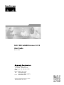
SCE 1000 2xGBE Release 2.0.10
User Guide
OL-7117-02
Corporate Headquarters
C isco Sys te ms , Inc .
1 70 W es t Tas ma n D r i ve
Sa n Jose , C A 9 513 4-1 706
USA
h t t p : / /w w w .c i s c o .co m
T e l: 4 08 5 26- 400 0
8 00 5 53-NET S ( 638 7)
F a x : 4 08 5 26- 410 0
Customer Order Number: DOC-7117-02=
Text Part Number: OL-7117-02
THE SPECIFICATIONS AND INFORMATION REGARDING THE PRODUCTS IN THIS MANUAL ARE SUBJECT TO CHANGE WITHOUT NOTICE. ALL STATEMENTS,
INFORMATION, AND RECOMMENDATIONS IN THIS MANUAL ARE BELIEVED TO BE ACCURATE BUT ARE PRESENTED WITHOUT WARRANTY OF ANY KIND,
EXPRESS OR IMPLIED. USERS MUST TAKE FULL RESPONSIBILITY FOR THEIR APPLICATION OF ANY PRODUCTS.
THE SOFTWARE LICENSE AND LIMITED WARRANTY FOR THE ACCOMPANYING PRODUCT ARE SET FORTH IN THE INFORMATION PACKET THAT SHIPPED
WITH THE PRODUCT AND ARE INCORPORATED HEREIN BY THIS REFERENCE. IF YOU ARE UNABLE TO LOCATE THE SOFTWARE LICENSE OR LIMITED
WARRANTY, CONTACT YOUR CISCO REPRESENTATIVE FOR A COPY.
The following information is for FCC compliance of Class A devices: This equipment has been tested and found to comply with the limits for a Class A digital device, pursuant to part 15
of the FCC rules. These limits are designed to provide reasonable protection against harmful interference when the equipment is operated in a commercial environment. This equipment
generates, uses, and can radiate radio-frequency energy and, if not installed and used in accordance with the instruction manual, may cause harmful interference to radio communications.
Operation of this equipment in a residential area is likely to cause harmful interference, in which case users will be required to correct the interference at their own expense.
The following information is for FCC compliance of Class B devices: The equipment described in this manual generates and may radiate radio-frequency energy. If it is not installed in
accordance with Cisco’s installation instructions, it may cause interference with radio and television reception. T his equipment has been tested and found to comply with the limits for a
Class B digital device in accordance with the specifications in part 15 of the FCC rules. These specifications are designed to provide reasonable protection against such interference in a
residential installation. However, there is no guarantee that interference will not occur in a particular installation.
Modifying the equipment without Cisco’s written authorization may result in the equipment no longer complying with FCC requirements for Class A or Class B digital devices. In that
event, your right to use the equipment may be limited by FCC regulations, and you may be required to correct any interference to radio or television communications at your own
expense.
You can determine whether your equipment is causing interference by turning it off. If the interference stops, it was probably caused by the Cisco equipment or one of its peripheral
devices. If the equipment causes interference to radio or television reception, try to correct the interference by using one or more of the following measures:
•
Turn the television or radio antenna until the interference stops.
•
Move the equipment to one side or the other of the television or radio.
•
Move the equipment farther away from the television or radio.
•
Plug the equipment into an outlet that is on a different circuit from the television or radio. (That is, make certain the equipment and the television or radio are on circuits controlled
by different circuit breakers or fuses.)
Modifications to this product not authorized by Cisco Systems, Inc. could void the FCC approval and negate your authority to operate the product.
The Cisco implementation of TCP header compression is an adaptation of a program developed by the University of California, Berkeley (UCB) as part of UCB’s public domain version
of the UNIX operating system. All rights reserved. Copyright © 1981, Regents of the University of California.
NOTWITHSTANDING ANY OTHER WARRANTY HEREIN, ALL DOCUMENT FILES AND SOFTWARE OF THESE SUPPLIERS ARE PROVIDED “AS IS” WITH ALL
FAULTS. CISCO AND THE ABOVE-NAMED SUPPLIERS DISCLAIM ALL WARRANTIES, EXPRESSED ORIMPLIED, INCLUDING, WITHOUT LIMITATION, THOSE OF
MERCHANTABILITY, FITNESS FOR A PARTICULAR PURPOSE AND NONINFRINGEMENT OR ARISING FROM A COURSE OF DEALING, USAGE, OR TRADE
PRACTICE.
IN NO EVENT SHALL CISCO OR ITS SUPPLIERS BE LIABLE FOR ANY INDIRECT, SPECIAL, CONSEQUENTIAL, OR INCIDENTAL DAMAGES, INCLUDING, WITHOUT
LIMITATION, LOST PROFITS OR LOSS OR DAMAGE TO DATA ARISING OUT OF THE USE OR INABILTY TO USE THIS MANUAL, EVEN IF CISCO OR ITS SUPPLIERS
HAVE BEEN ADVISED OF THE POSSIBILITY OF SUCH DAMAGES.
CCSP, the Cisco Square Bridge logo, Follow Me Browsing, and StackWise are trademarks of Cisco Systems, Inc.; Changing the Way We Work, Live, Play, and Learn, and iQuick Study
are service marks of Cisco Systems, Inc.; and Access Registrar, Aironet, ASIST, BPX, Catalyst, CCDA, CCDP, CCIE, CCIP, CCNA, CCNP, Cisco, the Cisco Certified Internetwork
Expert logo, Cisco IOS, Cisco Press, Cisco Systems, Cisco Systems Capital, the Cisco Systems logo, Cisco Unity, Empowering the Internet Generation, Enterprise/Solver, EtherChannel,
EtherFast, EtherSwitch, Fast Step, FormShare, GigaDrive, GigaStack, HomeLink, Internet Quotient, IOS, IP/TV, iQ Expertise, the iQ logo, iQ Net Readiness Scorecard, LightStream,
Linksys, MeetingPlace, MGX, the Networkers logo, Networking Academy, Network Registrar, Packet, PIX, Post-Routing, Pre-Routing, ProConnect, RateMUX, ScriptShare, SlideCast,
SMARTnet, StrataView Plus, SwitchProbe, TeleRouter, The Fastest Way to Increase Your Internet Quotient, TransPath, and VCO are registered trademarks of Cisco Systems, Inc. and/or
its affiliates in the United States and certain other countries.
All other trademarks mentioned in this document or Website are the property of their respective owners. The use of the word partner does not imply a partnership relationship between
Cisco and any other company. (0501R)
Printed in the USA on recycled paper containing 10% postconsumer waste.
SCE 1000 2xGBE User Guide Release 2.0.10
Copyright © 2002-2005 Cisco Systems, Inc.
All rights reserved.
CONTENTS
Preface xi
Audience xi
Purpose xi
Document Content xii
Document Conventions xiii
Related Publications xiii
Obtaining Technical Assistance xiii
Cisco TAC Website xiv
Opening a TAC Case xiv
TAC Case Priority Definitions xiv
Regulatory Compliance and Safety Information xvii
Regulatory Compliance xvii
Industry EMC, Safety, and Environmental Standards xviii
EC Declaration of Conformity xviii
Federal Communications Commission (FCC) Compliance Notice: xix
CSA NRTL (Canada) xix
ULC (Canada) xix
Regulatory Symbols xix
Warning Definition Statement xx
Installation Warnings xxi
Product Disposal Warning xxi
Jewelry Removal Warning xxi
Lightning Activity Warning xxi
Service Personnel Warning xxi
Australia SA/NZS 3260 Warning xxi
Ground Connection Warning xxii
Grounded Equipment Warning xxii
Grounding Warning xxii
SCE 1000 2xGBE Release 2.0.10 User Guide
OL-7117-02
i
Contents
Protective Earth Warning xxii
Ground Conductor Warning xxii
FCC Warning xxiii
Restricted Area Warning (DC platform only) xxiii
Wrist Strap Warning xxiii
Power Disconnection Warning xxiii
Power Supply Warning xxiii
Power Supply Disconnection Warning xxiii
Chassis Power Connection Warning (DC platform only) xxiv
SELV Circuit Warning xxiv
WAN Port Static Shock Warning xxiv
Class 1/I Laser Product Warning xxiv
Battery Handling Warning xxiv
Fan Tray Removal Warning xxv
Overview 1-1
The Cisco Service Control Concept 1-1
Service Control for Wireless Service Providers 1-2
Service Control for DSL Providers and ISPs 1-2
Service Control for Cable MSOs 1-2
Service Control Capabilities 1-3
The SCE Platform 1-4
Management and Collection 1-5
Network Management 1-5
Subscriber Management 1-6
Service Configuration Management 1-6
Collection 1-6
Cisco Service Control Specific Solutions 1-6
Service Control Application Suite for Broadband 1-7
Service Control Application Suite for Mobile 1-7
SCE 1000 2xGBE Release 2.0.10 User Guide
ii
OL-7117-02
Contents
Topology 2-1
Issues to Be Considered 2-1
SCE Platform Configuration 2-2
Failure Detection Mechanism 2-2
Bypass Mechanism 2-2
Functionality 2-3
Physical Installation 2-3
Bump-in-the-Wire (Inline) Topology 2-4
External Splitting (Receive-only) Topology 2-4
Redundancy 2-5
Two Platforms on Parallel Links in Bump-in-the-Wire Topology 2-5
Failure and Recovery 2-6
Physical Installation 2-7
Redundancy 2-7
Maintaining the Network Links vs Maintaining SCE 1000 Platform Functionality 27
Topology-Related Parameters 2-7
Connection Mode Parameter 2-8
On-Failure Mode Parameter 2-8
Link Failure Reflection Parameter 2-9
Status of the SCE 1000 After Abnormal Boot 2-9
Command Line Interface 3-1
Authorization and Command Levels (Hierarchy) 3-1
CLI Authorization Levels 3-2
CLI Command Hierarchy 3-4
Prompt Indications 3-10
CLI Help Features 3-11
Partial Help 3-11
Argument Help 3-11
The [no] Prefix 3-12
Navigational and Shortcut Features 3-13
Command History 3-13
Keyboard Shortcuts 3-13
SCE 1000 2xGBE Release 2.0.10 User Guide
OL-7117-02
iii
Contents
Tab Completion 3-14
FTP User Name and Password 3-14
CLI Scripts 3-15
Installation and Startup 4-1
Pre-Installation Requirements 4-1
Step 1: Unpacking 4-1
Step 2: Checking Shipping Contents 4-2
Step 3: Preparing to Install 4-2
Installation 4-6
Installation Precautions 4-7
Installing the SCE 1000 on a Workbench or Tabletop 4-7
Mounting the SCE 1000 in a Rack 4-8
Connecting to the Power Supply 4-13
Back Panel 4-14
Attaching a Chassis Ground Connection 4-15
Connecting the AC Power Supply Cable 4-17
Connecting the DC Power Supply 4-18
Front Panel 4-19
Powering up 4-23
Connecting the Local Console 4-24
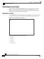
Setting Up the Local Console 4-24
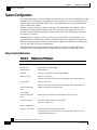
System Configuration 4-26
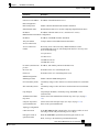
Setup Command Parameters 4-26
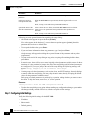
Step 1: Configuring Initial Settings 4-28
Step 2: Configuring the Hostname 4-29
Step 3: Setting the Passwords 4-30
Step 4: Configuring Time Settings 4-31
Step 5: Configuring the DNS Settings 4-33
Step 6: Configuring the RDR Formatter Destination 4-34
Step 7: Configuring Access Control Lists (ACLs) 4-35
Step 8: Configuring SNMP 4-38
Step 9: Configuring the Topology-Dependent Parameters 4-41
Step 10: Completing and Saving the Configuration 4-44
SCE 1000 2xGBE Release 2.0.10 User Guide
iv
OL-7117-02
Contents
Connecting the FE Management Port 4-46
Connecting the line ports to the network 4-48
Bump-in-the-Wire (Inline) Topology 4-49
External Optical Splitter (Receive-only) Topology 4-49
Configuring the GBE Interface Parameters 4-50
Testing Connectivity: Examining Link LEDs and Counters 4-53
Loading and Activating a Service Control Application 4-55
Final Tests 4-55
Verifying Operational Status 4-55
Viewing the User Log 4-56
Configuration and Management 5-1
Setup Utility 5-1
Multiple entry parameters (Lists) 5-2
File-system Operations 5-3
Working with Directories 5-3
Working with Files 5-5
Viewing Configuration and Status 5-7
Saving the Configuration Settings 5-12
Recovering a Previous Configuration 5-14
Entering and Exiting Global Configuration Mode 5-15
Passwords 5-16
Upgrading SCE Platform Firmware 5-19
The User Log 5-20
The Logging System 5-20
Generating a File for Technical Support 5-25
Rebooting and Shutting Down the SCE Platform 5-25
Rebooting the SCE Platform 5-25
Shutting Down the SCE Platform 5-26
Control Configuration 6-1
Entering and Exiting Global Configuration Mode 6-1
SCE Platform Management Interfaces 6-2
Configuring the Available Interfaces 6-2
Configuring Access Control Lists (ACLs) 6-2
SCE 1000 2xGBE Release 2.0.10 User Guide
OL-7117-02
v
Contents
Telnet Interface 6-5
SNMP Interface 6-6
IP Configuration 6-7
IP Routing Table 6-7
IP Advertising 6-9
Time Clocks and Time Zone 6-11
Showing System Time 6-11
Showing Calendar Time 6-11
Setting the Clock 6-12
Setting the Calendar 6-12
Setting the Time Zone 6-13
Removing Current Time Zone Setting 6-13
SNTP 6-13
Enabling SNTP multicast client 6-14
Disabling SNTP multicast client 6-14
Enabling SNTP unicast client 6-14
Disabling SNTP unicast client 6-15
Defining the SNTP unicast update interval 6-15
Display SNTP information 6-16
Domain Name (DNS) Settings 6-16
Name Servers 6-17
Domain Name 6-18
Host Table 6-18
show hosts 6-19
The RDR Formatter 6-19
RDR Formatter Destinations 6-20
Categories 6-21
Priority 6-21
Protocol Version 6-22
Forwarding Modes 6-22
Configuring the RDR Formatter 6-23
Displaying RDR Formatter Configuration and Statistics 6-29
Disabling the LineCard from Sending RDRs 6-30
SCE 1000 2xGBE Release 2.0.10 User Guide
vi
OL-7117-02
Contents
SNMP Configuration and Management 6-31
SNMP Protocol 6-31
Configuration via SNMP 6-32
Security Considerations 6-32
SNMP Community Strings 6-33
Traps 6-34
CLI 6-38
MIBs 6-39
MIB-II 6-39
Cisco Enterprise MIB 6-40
Failure Recovery Mode 6-41
Entering FastEthernet (Management) Interface Configuration Mode 6-42
Management Interface Configuration Mode 6-43
Configuring the Management Interface Speed and Duplex Parameters 6-43
Entering LineCard Interface Configuration Mode 6-44
Configuring Applications 6-45
Line Configuration 7-1
Entering LineCard Interface Configuration Mode 7-2
Configuring Tunneling Protocols 7-2
Selecting the Tunneling Mode 7-3
Displaying Tunneling Configuration 7-5
Configuring Traffic Rules and Counters 7-5
Traffic Rules 7-6
Traffic counters 7-6
Configuring Traffic Counters 7-7
Configuring Traffic Rules 7-7
Managing Traffic Rules and Counters 7-10
Configuring TOS Marking 7-12
Enabling and Disabling TOS Marking 7-12
Modifying the TOS Table 7-13
Editing the Connection Mode 7-13
Enforcing the Link Mode 7-14
Enabling and Disabling Link Failure Reflection 7-15
SCE 1000 2xGBE Release 2.0.10 User Guide
OL-7117-02
vii
Contents
Line Gigabit Ethernet Interfaces 7-15
Entering GigabitEthernet Line Interface Configuration Mode 7-16
Configuring GigabitEthernet Auto-Negotiation 7-16
Managing Subscribers 8-1
Subscriber Overview 8-1
Subscriber Modes in Service Control Solutions 8-3
Aging Subscribers 8-4
Anonymous Groups and Subscriber Templates 8-5
Subscriber Files 8-5
Importing/Exporting Subscriber Information 8-6
Importing/Exporting Subscribers 8-7
Importing/Exporting Anonymous Groups 8-7
Importing/Exporting Subscriber Templates 8-8
Removing Subscribers and Templates 8-8
Monitoring Subscribers 8-10
Monitoring the Subscriber Database 8-11
Displaying Subscribers 8-12
Displaying Subscriber Information 8-15
Displaying Anonymous Subscriber Information 8-16
Subscriber Aging 8-18
Identifying And Preventing Distributed-Denial-Of-Service Attacks 9-1
Attack Filtering 9-1
Attack Detection 9-2
Attack Detection Thresholds 9-3
Attack Handling 9-3
Subscriber Notification 9-4
Configuring Attack Detectors 9-5
Enabling Specific-IP Detection 9-7
Default Attack Detector 9-7
Specific Attack Detectors 9-8
Sample Attack Detector Configuration 9-10
Configuring Subscriber Notifications 9-11
Subscriber Notification Ports 9-11
SCE 1000 2xGBE Release 2.0.10 User Guide
viii
OL-7117-02
Contents
Managing Attack Filtering 9-12
Preventing Attack Filtering 9-13
Forcing Attack Filtering 9-13
Monitoring Attack Filtering 9-14
Troubleshooting 10-1
Document Conventions 10-1
Front Panel LEDs 10-2
Management Link 10-5
RDR Reports 10-6
GBE Interfaces Connectivity 10-10
Software Package Installation 10-12
User Log 10-14
Maintenance 11-1
Replacing the Battery 11-1
Replacing the Fan Module 11-2
Replacing the Power Module 11-3
CLI Command Reference A-1
Proprietary MIB Reference B-1
Glossary of Terms 1
Index 1
SCE 1000 2xGBE Release 2.0.10 User Guide
OL-7117-02
ix
Preface
This guide contains instructions on how to install and run the SCE 1000 Platform. This guide
assumes a basic familiarity with telecommunications equipment and installation procedures.
Throughout the book, the procedures shown are examples of how to perform typical SCE
platform management functions. Because of the large number of functions available, not every
possible procedure is documented in the instructional chapters. The CLI Command Reference (on
page A-1) provides a complete listing of all possible commands. The other chapters provide
examples of how to implement the most common of these commands, general information on the
interrelationships between the commands and the conceptual background of how to use them.
Audience
This guide is for the networking or computer technician responsible for installing and configuring
the SCE 1000 Platform on-site. It is also intended for the operator who manages the SCE 1000
Platform(s). This manual does not cover high-level technical support procedures available to Root
administrators and Cisco technical support personnel.
Purpose
The SCE 1000 2xGBE User Guide documents the SCE Platform hardware and software
components and how they analyze network transactions and generate the data records (RDRs). It
describes the features of these components and how they interact with other components of the
Cisco Service Control Solution.
SCE 1000 2xGBE Release 2.0.10 User Guide
OL-7117-02
xi
Preface
Document Content
Document Content
This manual covers the following topics:
Regulatory Compliance and Safety Information contains a list of the warnings and regulations
applicable to the SCE Platform.
Chapter 1: Overview provides a general overview of the Service Control Solution and the SCE
1000 Platform.
Chapter 2: Topology describes the possible deployment topologies of the SCE 1000 and explains
how various aspects of the topology determine the configuration of the system.
Chapter 3: Command Line Interface describes how to use the SCE 1000 Command Line Interface
(CLI), its hierarchical structure, authorization levels and its help features.
Chapter 4: Installation and Startup describes the procedures for installing the SCE 1000 Platform
on-site, how to configure it, and how to initiate the platform within a service provider network.
Chapter 5: Configuration and Management provides general guidelines for configuring and
managing the SCE 1000 by means of the Command Line Interface (CLI). It covers basic topics
such as the setup utility, file operations, system monitoring, saving and recovering configurations,
and the user log.
Chapter 6: Control Configuration discusses the available SCE 1000 platform management
interfaces and how to configure them. It explains how to configure and manage SCE 1000 global
parameters; including time zone, Internet Protocol, domain name settings and SNMP .It also
explains how to configure and manage service-related functions, such as RDR configuration, TOS
marking, and application configuration
Chapter 7: Line Configuration discusses how to configure and manage SCE 1000 line card
interfaces; including tunneling, traffic port configuration, connection mode and link mode.
Chapter 8: Managing Subscribers explains how to import and export various subscriber files and
how to monitor subscribers.
Chapter 9: Identifying And Preventing Distributed- Denial-Of-Service Attacks explains how to
configure the SCE 1000 attack filtering functionality.
Chapter 10: Troubleshooting discusses the common problems and solutions when configuring the
SCE 1000 or one of its components.
Chapter 11: Maintenance gives instructions for performing periodical hardware maintenance
procedures which need to be carried out to keep the SCE 1000 running optimally.
Appendix A: CLI Command Reference provides a list of the available CLI commands that you can
use to configure the SCE 1000.
Appendix B: Proprietary MIB Reference describes the SCE platform proprietary MIB supported
by the SCE 1000 platform.
Glossary: Brief description of terms used throughout this guide.
SCE 1000 2xGBE Release 2.0.10 User Guide
xii
OL-7117-02
Preface
Document Conventions
Document Conventions
The following typographic conventions are used in this guide:
Typeface or Symbol
Meaning
Italics
References, new terms, field names, and placeholders.
Bold
Names of menus, options, and command buttons.
Courier
System output shown on the computer screen in the Telnet session.
Courier Bold
CLI code typed in by the user in examples.
Courier Italic
Required parameters for CLI code.
[italic in
brackets]
Optional parameters for CLI code.
Note.
Notes contain important information.
Warning.
Warning means danger of bodily injury or of damage to equipment.
The CLI commands are written in the following format:
command RequiredParameter constant [optional-parameter]
[no] is an optional parameter that may appear before the command name.
When typing commands, you may enclose parameters in double-quote marks, and you must do so
when there is a space or a question mark within a parameter name.
Examples are shown in courier style. Bold courier is used to show the commands as you type
them and regular courier is used for system prompts and responses.
Related Publications
This SCE 1000 2xGBE User Guide should be used in conjunction with the Service Control
Management Suite User Guides (Subscriber Management User Guide, Service Control
Application Suite for Broadband User Guide, Service Control Application Suite for Mobile User
Guide and the Collection Manager User Guide).
Obtaining Technical Assistance
For all customers, partners, resellers, and distributors who hold valid Cisco service contracts, the
Cisco Technical Assistance Center (TAC) provides 24-hour, award-winning technical support
services, online and over the phone. Cisco.com features the Cisco TAC website as an online
starting point for technical assistance.
SCE 1000 2xGBE Release 2.0.10 User Guide
OL-7117-02
xiii
Preface
Obtaining Technical Assistance
Cisco TAC Website
The Cisco TAC website (http://www.cisco.com/tac (http://www.cisco.com/tac)) provides online
documents and tools for troubleshooting and resolving technical issues with Cisco products and
technologies. The Cisco TAC website is available 24 hours a day, 365 days a year.
Accessing all the tools on the Cisco TAC website requires a Cisco.com user ID and password. If
you have a valid service contract but do not have a login ID or password, register at this URL:
http://tools.cisco.com/RPF/register/register.do (http://tools.cisco.com/RPF/register/register.do)
Opening a TAC Case
The online TAC Case Open Tool (http://www. cisco.com/tac/caseopen
(http://www.cisco.com/tac/caseopen)) is the fastest way to open P3 and P4 cases. (Your network is
minimally impaired or you require product information). After you describe your situation, the
TAC Case Open Tool automatically recommends resources for an immediate solution.
If your issue is not resolved using these recommendations, your case will be assigned to a Cisco
TAC engineer.
For P1 or P2 cases (your production network is down or severely degraded) or if you do not have
Internet access, contact Cisco TAC by telephone. Cisco TAC engineers are assigned immediately
to P1 and P2 cases to help keep your business operations running smoothly.
To open a case by telephone, use one of the following numbers:
Asia-Pacific: +61 2 8446 7411 (Australia: 1 800 805 227)
EMEA: +32 2 704 55 55
USA: 1 800 553-2447
For a complete listing of Cisco TAC contacts, go to this URL:
http://www.cisco.com/warp/public/687/Directory/DirTAC.shtml
(http://www.cisco.com/warp/public/687/Directory/DirTAC.shtml)
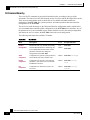
TAC Case Priority Definitions
To ensure that all cases are reported in a standard format, Cisco has established case priority
definitions.
•
Priority 1 (P1)—Your network is “down” or there is a critical impact to your business
operations. You and Cisco will commit all necessary resources around the clock to resolve the
situation.
•
Priority 2 (P2)—Operation of an existing network is severely degraded, or significant aspects
of your business operation are negatively affected by inadequate performance of Cisco
products. You and Cisco will commit full-time resources during normal business hours to
resolve the situation.
•
Priority 3 (P3)—Operational performance of your network is impaired, but most business
operations remain functional. You and Cisco will commit resources during normal business
hours to restore service to satisfactory levels.
SCE 1000 2xGBE Release 2.0.10 User Guide
xiv
OL-7117-02
Preface
Obtaining Technical Assistance
•
Priority 4 (P4)—You require information or assistance with Cisco product capabilities,
installation, or configuration. There is little or no effect on your business operations.
SCE 1000 2xGBE Release 2.0.10 User Guide
OL-7117-02
xv
Regulatory Compliance and Safety Information
This chapter provides international agency compliance, safety, and statutory information
concerning the SCE 1000. It also summarizes and highlights all of the safety warnings associated
with handling, installing and operating the SCE 1000.
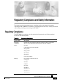
Regulatory Compliance
The SCE 1000 is in compliance with the national and international specification standards
described in the following table:
Table 1-1
Regulatory Compliance
Specifications
Description
Regulatory
Compliance
Products bear CE[1] Marking indicating compliance with the 1999/5/EEC
directive, which includes the following safety and EMC standards.
Safety
UL 1950,
CAN/CSA[2]-C22.2 No. 60950-00
EN[3] 60950
IEC[4] 60950
IEC 60825-1
EN 60825-1
Class I laser product
EMC[5]
FCC[6] Part 15 (CFR 47) Class A
ICES[7]-003
EN55022
CISPR22
EN 55024
EN50082-1
EN61000-3-2
EN61000-3-3
VCCI Class A
SCE 1000 2xGBE Release 2.0.10 User Guide
OL-7117-02
xvii
Regulatory Compliance and Safety Information
Industry EMC, Safety, and Environmental Standards
[1] CE = Committee European
[2] CSA = Canadian Standards Association
[3] EN = European Norm
[4] IEC = International Electrotechnical Commission
[5] EMC = electromagnetic compatibility
[6] FCC = Federal Communications Commission
[7] ICES = Interference-Causing Equipment Standard
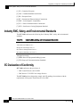
Industry EMC, Safety, and Environmental Standards
The SCE 1000 conforms to the following list of industry EMC, safety, and environmental
standards:
Table 1-2
Industry EMC, Safety, and Environmental Standards
*GR-63-Core NEBS[1] Level 3
*GR-1089-Core NEBS Level 3
ETS[2] 300 019 Storage Class 1.1
ETS 300 019 Transportation Class 2.3
ETS 300 019 Stationary Use Class 3.1
*Designed to comply
[1] NEBS=Network Equipment Building Systems
[2] ETS=European Telecommunications Standards
EC Declaration of Conformity
SCE 1000 conforms to the provisions of:
•
EMC Council Directive 89/336/EEC
•
EMC directive 73/23/EEC low voltage directive.
The SCE 1000 has been designed to comply with CE markings in accordance with the
requirements of European Council Directive 93/68 EEC.
SCE 1000 2xGBE Release 2.0.10 User Guide
xviii
OL-7117-02
Regulatory Compliance and Safety Information
Federal Communications Commission (FCC) Compliance Notice:
Federal Communications Commission (FCC) Compliance Notice:
This equipment complies with the limits for digital devices, pursuant to Part 15 of the FCC rules.
These limits are designed to provide reasonable protection against harmful interference when the
equipment is operated in a commercial environment. This equipment generates, uses, and can
radiate radio frequency energy. If it is not installed and used in accordance with the instruction
manual, it may cause harmful interference to radio communications. Operation of this equipment
in a residential area is likely to cause harmful interference, in which case users will be required to
take whatever measures may be necessary to correct the interference at their own expense.
This equipment complies with the UL1950, the system must be connected to secondary circuits
that are electrically isolated from accesses and connected to earth.
CSA NRTL (Canada)
This equipment is designed to meet the CSA requirements of UL1950, Safety of Information
Technology Equipment. CSA is listed by the American Federal OSHA as equivalent to UL and
other American safety testing laboratories under the NRTL program.
ULC (Canada)
The Industry Canada (formerly known as the Department of Communications) label identifies
certified equipment. This certification means that the equipment meets certain
telecommunications network protective, operational and safety requirements. Industry Canada
does not guarantee that equipment will operate to the user’s satisfaction.
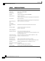
Regulatory Symbols
The following table displays regulatory symbols used.
These symbols are described in IEC412.
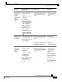
Table 1-3
Regulatory Symbols
Symbol
Icon
Description
ON Position
Indicates operating
Power ON
Power OFF
O
Off position
Indicates OFF
Protective
ground
terminal
Indicates a terminal that must be connected to earth ground prior
to making any other connections to the equipment
Dangerous
Voltage
Warning about high voltage
SCE 1000 2xGBE Release 2.0.10 User Guide
OL-7117-02
xix
Regulatory Compliance and Safety Information
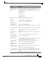
Warning Definition Statement
Symbol
Icon
Instructions
and warning
Description
Warning sign and/or intent to alert the user to the presence of
important operating and maintenance (servicing) instructions in
the product documentation.
Warning Definition Statement
Warning:
This warning symbol means danger. You are in a situation that could cause bodily injury. Before you
work on any equipment, be aware of the hazards involved with electrical circuitry and be familiar
with standard practices for preventing accidents.
The following warnings are listed in this document:
•
Installation Warnings
•
Product Disposal Warning
•
Jewelry Removal Warning
•
Lightning Activity Warning
•
Service Personnel Warning
•
Australia SA/NZS 3260 Warning
•
Ground Connection Warning
•
Grounded Equipment Warning
•
Grounding Warning
•
Protective Earth Warning
•
Ground Conductor Warning
•
FCC Warning
•
Restricted Area Warning
•
Wrist Strap Warning
•
Power Disconnection Warning
•
Power Supply Warning
•
Power Supply Disconnection Warning
•
Chassis Power Connection Warning
•
SELV Circuit Warning
•
WAN Port Static Shock Warning
•
Class 1/I Laser Product Warning
•
Battery Handling Warning
SCE 1000 2xGBE Release 2.0.10 User Guide
xx
OL-7117-02
Regulatory Compliance and Safety Information
Warning Definition Statement
•
Fan Tray Removal Warning (on page xxv)
Installation Warnings
Only trained and qualified personnel should be allowed to install, replace, or service this
equipment.
Warning:
Read the installation instructions before you connect the system to its power source.
Product Disposal Warning
Warning:
Ultimate disposal of this product should be handled according to all national laws and regulations.
Jewelry Removal Warning
Warning:
Before working on equipment that is connected to power lines, remove jewelry (including rings,
necklaces, and watches). Metal objects will heat up when connected to power and ground and can
cause serious burns or weld the metal object to the terminals.
Lightning Activity Warning
Warning:
Do not work on the system, or connect or disconnect cables during periods of lightning activity.
Service Personnel Warning
Warning:
This equipment is to be installed and maintained by service personnel only as defined by AS/NZS
3260 Clause 1.2.14.3 Service Personnel.
Australia SA/NZS 3260 Warning
The cores in the mains leads are colored in accordance with the following code:
Table 1-4
Australia SCE 1000 Lead Color
Lead Color
Function
Green and Yellow
Earth
Blue
Neutral
Brown
Live
SCE 1000 2xGBE Release 2.0.10 User Guide
OL-7117-02
xxi
Regulatory Compliance and Safety Information
Warning Definition Statement
The colors of the cores in the main leads may not correspond with the colored markings
identifying the terminals in the plug if power supply cord rewiring is required. Following are the
colors of the main leads of this equipment:
•
The green and yellow colored core must be connected to the terminal in the plug, which is
marked with the letter E or by the earth symbol, or colored green and yellow.
•
The blue core must be connected to the terminal, which is marked with the letter N or colored
black.
•
The brown core must be connected to the terminal, which is marked with the letter L or
colored red.
Ground Connection Warning
Warning:
When installing the unit, always make the ground connection first and disconnect it last.
Grounded Equipment Warning
Warning:
This equipment is intended to be grounded. Ensure that the host is connected to earth ground during
normal use.
Grounding Warning
Warning:
This equipment is Class 1 type and must be permanently earthed for protection and functional
purposes. For safe operation and servicing, install the AC socket outlet near the equipment so that it is
readily accessible .Use the appropriate AC power cord and plug, as required by national standards.
This equipment must be permanently earthed.
Protective Earth Warning
Warning:
Protective earth is referred to as chassis ground in this document. To make protective earth
connection, use the two-hole compression lug grounding points on the back panel.
Ground Conductor Warning
Warning:
Never defeat the ground conductor or operate the equipment in the absence of a suitably installed
ground conductor. Contact the appropriate electrical inspection authority or an electrician if you are
uncertain that suitable grounding is available.
SCE 1000 2xGBE Release 2.0.10 User Guide
xxii
OL-7117-02
Regulatory Compliance and Safety Information
Warning Definition Statement
FCC Warning
Note:
This equipment has been tested and found to comply with the limits for a Class B digital device,
pursuant to Part 15 of the FCC rules. These limits are designed to provide reasonable protection
against harmful interference when the equipment is operated in a commercial environment. This
equipment generates, uses, and can radiate radio frequency energy and, if not installed and used in
accordance with the instruction manual, may cause harmful interference to radio communications.
Operation of this equipment in a residential area is likely to cause harmful interference in which case
the user will be required to correct the interference at his own expense.
Restricted Area Warning (DC platform only)
Warning:
This unit is intended for installation in restricted access areas. A restricted access area is where access
can only be gained by service personnel through the use of a special tool, lock and key, or other
means of security, and is controlled by the authority responsible for the location.
Wrist Strap Warning
Warning:
During this procedure, wear grounding wrist straps to avoid ESD damage to the card. Do not directly
touch the back plane with your hand or any metal tool, or you could shock yourself.
Power Disconnection Warning
Warning:
Before working on a system that has an on/off switch, turn OFF the power and unplug the power
cord.
Power Supply Warning
Warning:
Do not touch the power supply when the power cord is connected. For systems with a power switch,
line voltages are present within the power supply even when the power switch is off and the power
cord is connected. For systems without a power switch, line voltages are present within the power
supply when the power cord is connected.
Power Supply Disconnection Warning
Warning:
Before working on a chassis or working near power supplies, unplug the power cord on AC units;
disconnect the power at the circuit breaker on DC units.
SCE 1000 2xGBE Release 2.0.10 User Guide
OL-7117-02
xxiii
Regulatory Compliance and Safety Information
Warning Definition Statement
Warning:
This unit may have more than one power supply cord. Disconnect all power supply cords before
servicing to avoid electric shock.
Chassis Power Connection Warning (DC platform only)
Warning:
Before connecting or disconnecting ground or power wires to the chassis, ensure that power is
removed from the DC circuit. To ensure that all power is OFF, locate the circuit breaker on the panel
board that services the DC circuit, switch the circuit breaker to the OFF position, and tape the switch
handle of the circuit breaker in the OFF position.
SELV Circuit Warning
Warning:
To avoid electric shock, do not connect safety extra-low voltage (SELV) circuits to telephone-network
voltage (TNV) circuits. LAN ports contain SELV circuits, and WAN ports contain TNV circuits.
Some LAN and WAN ports both use RJ-45 connectors. Use caution when connecting cables.
WAN Port Static Shock Warning
Warning:
Hazardous network voltages are present in WAN ports regardless of whether power to the unit is OFF
or ON. To avoid electric shock, use caution when working near WAN ports. When detaching cables,
detach the end away from the unit first.
Class 1/I Laser Product Warning
Warning:
Class 1/I Laser product complying with 21CFR 1040.10 and 1040.11 and IEC 60825-1: 1993 + A1: 1997 +
A2:2001.
Battery Handling Warning
Warning:
There is the danger of explosion if the battery is replaced incorrectly. Replace the battery only with
the same or equivalent type recommended by the manufacturer. Dispose of used batteries according to
the manufacturer’s instructions.
SCE 1000 2xGBE Release 2.0.10 User Guide
xxiv
OL-7117-02
Regulatory Compliance and Safety Information
Warning Definition Statement
Fan Tray Removal Warning
Warning:
When removing the fan drawer, keep hands and fingers away from the spinning fan blades. Let the
fan blades stop completely before removing the fan drawer.
SCE 1000 2xGBE Release 2.0.10 User Guide
OL-7117-02
xxv
CHAPTER 1
Overview
This chapter provides a general overview of the Cisco Service Control solution. It introduces the
Cisco Service Control concept and the Service Control capabilities. It also briefly describes the
hardware capabilities of the SCE Platform, as well as the Cisco specific applications that together
compose the total Cisco Service Control solution.
Step 1 This chapter contains the following sections:
• The Cisco Service Control Concept
• Service Control Capabilities
1-1
1-3
• The SCE Platform 1-4
• Management and Collection
1-5
• Cisco Service Control Specific Solutions 1-6
The Cisco Service Control Concept
The Cisco Service Control concept is delivered through a combination of purpose-built hardware
and specific software solutions that address various Service Control challenges faced by service
providers. The SCE Platform is designed to support observation, analysis, and control of
Internet/IP traffic.
Service Control enables service providers to create profitable new revenue streams while
capitalizing on their existing infrastructure. With the power of Service Control, service providers
have the ability to analyze, charge for, and control IP network traffic at multi-Gigabit wire line
speeds. The Cisco Service Control solution also gives service providers the tools they need to
identify and target high-margin, content-based services.
As the downturn in the telecommunications industry has shown, IP service provider business
models need to be reworked in order to make them profitable. Having spent billions of dollars to
build ever larger data links, providers have incurred massive debts and rising costs. During the
same time, access and bandwidth became a commodity where prices continually fell and profits
disappeared. Service providers now realize that they must offer value-added services to derive
more revenue from the traffic and services running on their networks. However, capturing real
profits from IP services requires more than simply running those services over data links; it
requires detailed monitoring and precision, real- time control and awareness of services as they
are delivered. Cisco provides Service Control solutions that allow the service provider to bridge
this gap.
SCE 1000 2xGBE Release 2.0.10 User Guide
OL-7117-02
1-1
Chapter 1
Overview
The Cisco Service Control Concept
Service Control for Wireless Service Providers
Wireless Service Providers are successfully rolling out 2.5G and 3G-based data services to their
subscribers.
These services are expected to significantly increase much needed Average Revenue Per User
(ARPU) for sustained business models and rapid rollout of new services. These data services
require new ways of service offering and new ways of billing these services to the subscribers.
The Cisco Service Control solutions enable:
•
Support for multiple billing models
•
Elimination of revenue leakage via real-time service control
•
Flexible pricing plans: postpaid, prepaid, MRC, pay-per-use
•
Content-based billing for various applications
•
Subscription-based and tiered application services
Service Control for DSL Providers and ISPs
DSL providers and ISPs targeting residential and business broadband customers must find new
ways to get maximum leverage from their existing infrastructures, while differentiating their
offerings with enhanced IP services.
Cisco products add a new layer of service intelligence and control to existing networks, and will:
•
Provide granular visibility into network usage
•
Automatically enforce application SLAs or acceptable use policies
•
Implement different service levels for different types of customers, content, or applications
•
Deploy from network edge to network core for end-to-end service control
•
Integrate Cisco solutions easily with existing network elements and BSS/ OSS systems
Service Control for Cable MSOs
Cable MSOs have successfully deployed high-speed cable modem services to millions of homes.
Now, they must move beyond providing commodity broadband access by introducing
differentiated services and by implementing the service control necessary to fully manage service
delivery through their broadband infrastructure. Cisco Service Control solutions will enable:
•
Ability to report/analyze network traffic at subscriber and aggregate level for capacity
planning
•
Identification of network abusers who are violating the Acceptable Use Policy
•
Identification and management of peer-to-peer, NNTP (news) traffic, and spam abusers
•
Enforcement of the Acceptable Use Policy (AUP)
•
Ability to limit the use of servers in the subscriber residence, as well as the use of multiple
(unpaid) computers
•
Customer-intuitive tiered application services and guarantee application SLAs
•
Full integration with standard or legacy OSS for subscriber management and billing
SCE 1000 2xGBE Release 2.0.10 User Guide
1-2
OL-7117-02
Chapter 1
Overview
Service Control Capabilities
Service Control Capabilities
At the core of the Cisco Service Control Platform stands the purpose-built network hardware
device: the Service Control Engine (SCE). Implementing a complete Service Control solution
requires that the Service Control Engine provide certain functionalities and capabilities. The
following are the core capabilities of the Cisco Service Control Engine, which support a wide
range of applications for delivering Service Control solutions:
•
Subscriber and application awareness: Application-level drilling into IP traffic for real-time
understanding and controlling of usage and content at the granularity of a specific subscriber.
•
Subscriber awareness: The ability to map between IP flows and a specific subscriber for
maintaining the state of each subscriber transmitting traffic through the platform, and
enforcing the appropriate policy on this subscriber traffic.
Subscriber awareness is achieved using dedicated integrations with subscriber
management repositories, such as a DHCP or a Radius server.
•
Application awareness: The ability to understand and analyze traffic up to the application
protocol layer (Layer 7).
For an application protocol that is implemented using bundled flows (such as FTP, which
is implemented using Control and Data flows), the SCE Platform understands the
bundling connection between the flows and treats them accordingly.
•
Stateful, real time traffic control: The ability to perform advanced control functions, including
granular BW metering and shaping, quota management and redirection, utilizing stateful realtime traffic transaction processing. This requires highly adaptive protocol and application
level intelligence.
•
Programmability: The ability to quickly add new protocols and easily adapt to new services
and applications in the ever-changing service provider environment. Programmability is
achieved using the SML language.
Programmability means that new services can be deployed quickly and provides an easy
upgrade path for network, application, or service growth.
•
Robust and flexible back office integration: The ability to integrate with existing 3rd party
systems at the Service Provider, such as provisioning systems, subscriber repositories, billing
systems, and OSS systems. The Service Control Engine provides a set of open and welldocumented APIs that allows a quick and robust integration process.
•
Scalable High-Performance Service Engines: The ability to execute all operations described
above at wire speed.
SCE 1000 2xGBE Release 2.0.10 User Guide
OL-7117-02
1-3
Chapter 1
Overview
The SCE Platform
The SCE Platform
The Service Control Engine family of programmable network devices is capable of performing
stateful flow inspection of IP traffic, and controlling that traffic based on configurable rules. The
Service Control Engine is a purpose-built network device making use of ASIC components and
RISC processors to go beyond packet counting and delve deeper into the contents of network
traffic. Providing programmable, stateful inspection of bi-direction traffic flows and mapping
these flows with user ownership, the Service Control Engine platforms provide a real-time
classification of network usage. This information provides the basis of the Service Control Engine
advanced traffic control and bandwidth shaping functionality. Where most bandwidth shaper
functionality ends, the Service Control Engine provides more control and shaping options
including:
•
Layer 7-3 stateful wire-speed packet inspection and classification
•
Robust support for over 600 protocol/applications including:
•
General: HTTP, HTTPS, FTP, TELNET, NNTP, SMTP, POP3, IMAP, WAP, and others
•
P2P: FastTrack-KazaA, Gnutella, WinMX, Winny, Hotline, eDonkey, DirectConnect,
Piolet, and others
•
Streaming & Multimedia: RTSP, SIP, HTTP-STREAMING, RTP/RTCP, and others
•
Programmable system core for flexible reporting and bandwidth control
•
Transparent network and BSS/OSS integration into existing networks
•
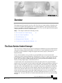
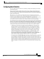
Subscriber awareness for relating traffic and usage to specific customers
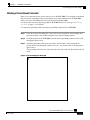
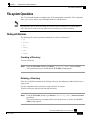
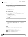
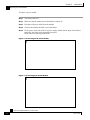
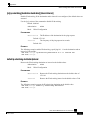
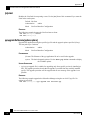
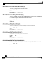
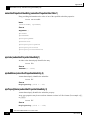
The following diagram demonstrates a deployment of an SCE Platform in the network.
Figure 1-1: SCE Platform in the Network
SCE 1000 2xGBE Release 2.0.10 User Guide
1-4
OL-7117-02
Chapter 1
Overview
Management and Collection
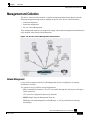
Management and Collection
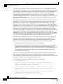
The Service Control solution includes a complete management infrastructure that provides the
following management components to manage all aspects of the Service Control solutions:
•
Network management
•
Subscriber management
•
Service Control Management
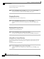
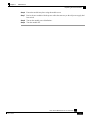
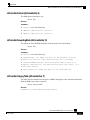
These management interfaces are designed to comply with common management standards and to
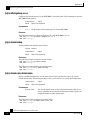
easily integrate with existing OSS infrastructure.
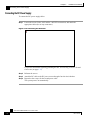
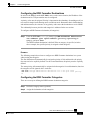
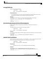
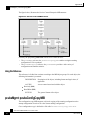
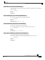
Figure 1-2: Service Control Management Infrastructure
Network Management
Cisco provides complete network FCAPS Management (Fault, Configuration, Accounting,
Performance, Security).
Two interfaces are provided for network management:
•
CLI (Command Line Interface). The CLI is accessible through the Console port or through a
Telnet connection.
CLI is used for configuration and security functions.
•
SNMP (Simple Network Management Protocol).
SNMP provides fault management via SNMP traps, as well as performance monitoring
functionality.
SCE 1000 2xGBE Release 2.0.10 User Guide
OL-7117-02
1-5
Chapter 1
Overview
Cisco Service Control Specific Solutions
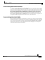
Subscriber Management
The smartSUB Manager (SM) is a middleware software component used for bridging between the
OSS and the SCE Platform(s). Subscriber information is stored in the SM database and can then
be distributed between multiple devices according to actual subscriber placement.
The SM provides subscriber awareness, mapping network IDs to subscriber IDs. It obtains
subscriber information using dedicated integration modules, which integrate with AAA devices
like Radius or DHCP servers.
Subscriber information may be introduced into the SCE platform in one of two ways:
•
Push Mode: The SM pushes subscriber information to the SCE Platform automatically upon
logon of a subscriber.
•
Pull Mode: On-demand, in response to a query from the SCE Platform to the SM.
Service Configuration Management
Service configuration management is the ability to configure the general service definitions of a
Service Control application. Service Configuration is performed by creating an XML file and then
applying it onto the SCE Platform using the Service Configuration utilities and management
commands. This XML based approach is simple to use and easy to automate.
Collection
All the analysis and data processing functions of the SCE Platform result in the generation of Raw
Data Records (RDRs). These RDRs are processed by the Collection Manager. The Collection
Manager software is an implementation of a collection system, listening in on RDRs from one or
more SCE Platforms. It collects these records, and processes them in one of its adapters. Each
adapter performs a specific action on the RDR.
RDRs contain a wide variety of information and statistics, depending on the configuration of the
system. There are three main categories of RDRs:
•
Transaction RDRs: Records generated for each transaction, where a transaction is a single
event detected in network traffic. The identification of a transaction will depend on the
particular application/protocol.
•
Subscriber RDRs: Records generated per subscriber, describing the traffic generated by that
subscriber for a defined interval.
•
Link RDRs: Records generated per link, describing the traffic carried on the link for a defined
interval.
Cisco Service Control Specific Solutions
Cisco provides two specific solutions that run on top of the SCE Platform. Each solution
addresses a different IP network control challenge that service providers face.
The Cisco specific solutions are:
•
Service Control Application Suite for Broadband
•
Service Control Application Suite for Mobile
SCE 1000 2xGBE Release 2.0.10 User Guide
1-6
OL-7117-02
Chapter 1
Overview
Cisco Service Control Specific Solutions
Service Control Application Suite for Broadband
The Service Control Application Suite for Broadband allows service providers to detect complex
and evasive network application protocols (such as P2P), and to control them as per their business
and service delivery requirements. It also enables the creation of differentiated tiered services that
the service provider uses to boost revenues and provide competitive services to end customers.
Service Control Application Suite for Broadband’s programmable application detection and
subscriber awareness makes tiered service possible from one central point in the network. The
Service Control Application Suite for Broadband requires no network changes or upgrades, and
is compatible with all existing IP network switches, routers, and infrastructure.
Service Control Application Suite for Mobile
In this solution the SCE Platform is instrumental as a real-time post- and pre-paid network billing
and traffic control device. It implements post-paid and pre-paid billing plans that relate subscriber
access and network bandwidth consumption. The Service Control Application Suite for Mobile
solution tracks detailed user specific traffic/application metrics and applies service and quota
controls depending on their pre-paid balances.
SCE 1000 2xGBE Release 2.0.10 User Guide
OL-7117-02
1-7
CHAPTER 2
Topology
This chapter describes the possible deployment topologies of the SCE 1000. The Cisco SCE
solution offers a number of basic topology options that permit the user to tailor the SCE Platform
to fit the needs of a particular installation. An understanding of the various issues and options is
crucial to designing, deploying, and configuring the topology that best meets the requirements of
the individual system.
Step 2 This chapter contains the following sections:
• Issues to Be Considered
• Functionality
2-3
• Physical Installation
• Redundancy
2-1
2-3
2-5
• Failure and Recovery
2-6
• Topology-Related Parameters
2-7
Issues to Be Considered
There are several issues that must be considered in order to arrive at the optimum configuration of
the topology-related parameters:
•
Functionality: Will the system be used solely to monitor traffic flow, with report functionality
only, or will it be used for traffic flow control, with enforcement as well as report
functionality?
•
Physical installation configuration: Will the SCE Platform be installed as inline? Or will the
SCE Platform use an optical splitter?
•
Redundancy: Must the system be designed to guarantee uninterrupted service? If so, there
must be a backup SCE Platform to assume operation in case of failure of the primary data
link.
•
Link failure and recovery: How should the SCE Platform respond to platform failure and
subsequent recovery? Should traffic flow continue even though the unit is not operating, or be
halted until the platform is repaired/replaced? Should the unit actually resume operation when
it is again operational?
SCE 1000 2xGBE Release 2.0.10 User Guide
OL-7117-02
2-1
Chapter 2
Topology
Issues to Be Considered
SCE Platform Configuration
There are four topology-related parameters:
•
Connection mode: Can be Inline or Receive-only, depending on the physical installation of
the SCE 1000:
May be configured via either the setup command or the connection-mode command.
•
Bypass mode when the SCE 1000 is not operational (on-failure): This parameter
determines whether the system cuts the traffic or bypasses it when the SCE 1000 has failed.
May be configured via either the setup command or the connection-mode command.
•
Status after reboot caused by fatal error or abnormal shutdown: This parameter
determines whether the SCE 1000 returns to normal operational state after a failure.
May be configured via either the setup command or the failure-recovery
operation-mode command.
•
Link failure reflection: This parameter determines the behavior of the system when there is a
link problem. In some topologies it is required that link failure on one port be reflected to the
other port, to allow the higher layer redundancy protocol in the network to function correctly.
May be configured via the link failure-reflection command only.
Failure Detection Mechanism
The SCE 1000 contains various mechanisms to monitor the status and to detect failures. The main
mechanisms are:
•
Boot time diagnostics failure. When there is a failure in diagnostics testing at boot time the
system will remain in failure status.
•
Watchdog mechanism. There are two types of watchdogs:
•
•
HW watchdog. A hardware mechanism that detects control entity failure.
•
SW watchdog. A software mechanism that periodically checks for software failures in the
SCE 1000. If a failure is detected, an error massage is sent and the SCE 1000 reboots.
Run time hardware tests. The system periodically tests the hardware components for error. If a
hardware component is malfunctioning, it will be discovered by the system within seconds.
Bypass Mechanism
The SCE 1000 includes a Network Interface Card with a bypass mechanism that is enabled upon
SCE 1000 failure. In addition, when connected in-line it can also be enabled in normal operation
to simultaneously bypass traffic flow to the other side and direct it internally for analysis. In this
case it maintains "receive-only"-like monitoring functions, when control functionality is not
required.
The bypass card supports the following four modes:
•
Bypass: The bypass mechanism preserves the network link, but traffic is not processed for
monitoring or for control.
SCE 1000 2xGBE Release 2.0.10 User Guide
2-2
OL-7117-02
Chapter 2
Topology
Functionality
•
Forwarding: This is the normal operational mode, in which the SCE 1000 processes the
traffic for monitoring and control purposes.
•
Sniffing: The bypass mechanism preserves the network link, while in parallel allowing the
SCE 1000 to process the traffic for monitoring only.
•
Cutoff: There is no forwarding of traffic, and the physical link is forced down (cutoff
functionality at layer 1).
Functionality
The SCE 1000 can serve one of two general functions:
•
Monitoring and Control: The SCE 1000 monitors and controls traffic flow. Decisions are
enforced by the SCE 1000 depending on the results of the monitoring functions of the SCE
1000 and the configuration of the Service Control Application for Broadband or Mobile
solution.
In order to perform control functions, the SCE 1000 must be physically installed as a bumpin-the-wire, and the connection mode must be “Inline”.
•
Monitoring only: The SCE 1000 monitors traffic flow, but cannot control it.
Either a bump-in-the-wire installation or an optical splitter installation may be used for
monitoring only. In the latter case connection mode must be “receive-only”.
Physical Installation
There are two options for the physical installation configuration of the SCE 1000 Platform:
•
Inline installation (provides control functionality).
•
Out-of-line installation utilizing an external optical splitte
The physical installation determines the connection mode that should be configured.
SCE 1000 2xGBE Release 2.0.10 User Guide
OL-7117-02
2-3
Chapter 2
Topology
Physical Installation
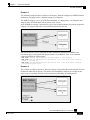
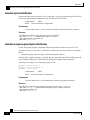
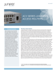
Bump-in-the-Wire (Inline) Topology
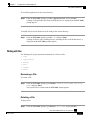
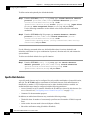
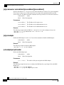
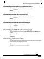
Typically, the SCE 1000 is connected on a full duplex line between two devices (Router, BRAS,
etc.). When the SCE 1000 is installed as a bump-in-the-wire, it physically resides on the data link
between the subscriber side and the network side, and can both receive and transmit traffic.
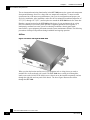
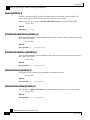
Figure 2-1: Bump-in-the-Wire Installation
A bump-in-the-wire installation is referred to as inline connection mode.
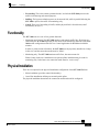
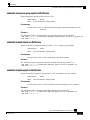
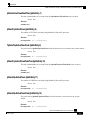
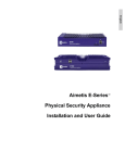
External Splitting (Receive-only) Topology
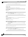
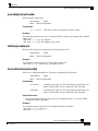
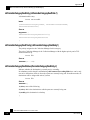
In external splitting, an external optical splitter resides physically on the GBE link between the
subscriber side and the network side. In this topology, the traffic passes through the external
splitter, which splits traffic to the SCE 1000. The external splitter is connected to the SCE 1000
via Rx links only. The SCE 1000, therefore, receives traffic only. It does not transmit.
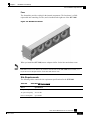
Figure 2-2: External Splitting Topology
SCE 1000 2xGBE Release 2.0.10 User Guide
2-4
OL-7117-02
Chapter 2
Topology
Redundancy
An external splitting installation is referred to as receive-only connection mode.
Note that in an external splitting installation, the SCE 1000 has only traffic monitoring
capabilities.
Note
Receive-only topologies can also be implemented using a switch. Such a switch must support SPAN
functionality that includes separation between ingress and egress traffic and multiple SPAN-ports
destinations.
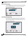
Redundancy
When a high degree of reliability is desired, a second SCE 1000 Platform should be installed to
provide backup operation capabilities. This redundant SCE 1000 guarantees uninterrupted
functioning of all SCE 1000 operations.
Note
Redundancy is possible in inline installations only.
A single SCE 1000 platform does not provide redundancy for SCE 1000 control functions. In case
of failure of the SCE 1000 unit, the SCE 1000 simply bypasses the traffic; the traffic link is not
cut, but no control or monitoring functionality is available.
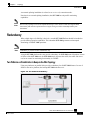
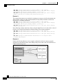
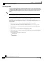
Two Platforms on Parallel Links in Bump-in-the-Wire Topology
Using two platforms on parallel links provides redundancy for all SCE 1000 features. In case of
failure in the active platform, the backup SCE 1000 unit takes over.
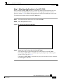
Figure 2-3: Two Platform Redundancy
SCE 1000 2xGBE Release 2.0.10 User Guide
OL-7117-02
2-5
Chapter 2
Topology
Failure and Recovery
The above figure represents the SCE 1000 redundant topology. It is applicable as an overlay to a
customer’s redundant topology, on condition that the entire traffic of a specific subscriber (end
station, subnet or VLAN) is flowing through one link only. Both links may be active, providing
that the subscriber traffic is mutually exclusive.
This redundancy solution addresses any failure in the SCE 1000 Platform itself. It is based on the
idea that any fatal hardware or software failure will cause the platform to “cut” the link. A “cut”
link will cause the routers/switches on both ends to switch the traffic to the standby link. On the
standby link, the traffic is analyzed and policies enforced by the standby SCE 1000, which, after
the failure, acts as the active SCE 1000.
Note that when both links are simultaneously independently active and redundant for the other
link (as is the case when HSRP with two virtual routers is used), if one link fails, its traffic is
directed to the other link. However, the overall supported load in the link that is now carrying all
the traffic is only equal to one link, not two.
During setup of this topology, the configuration of the two SCE 1000 platforms is done through
multi-box configuration. This ensures that both hold the same configurations and policies. The
functional operation of switching from the active to standby, SCE 1000 is contingent upon the
fact that the two SCE 1000 platforms are in the same Domain. All configurations performed on
this Domain are automatically updated on both SCE Platforms. Both boxes should also be
assigned to the same Subscriber Domain. For more information on Domains, see the smartSUB
Manager User Guide.
The common protocols used for redundancy traffic switching between network elements such as
routers and switches in networks are Spanning-Tree in layer2, HSRP in layer3 (usually used in
data-centers), and other common routing protocols like OSPF or RIP.
Note
When using routing/switching protocols that perform load balancing as well, the load balancing
capabilities should be disabled.
The transition to the backup SCE 1000 platform is transparent. Once the routers/switches detected
that traffic has been cut, they start sending traffic through the redundant link. After this occurs, the
failed SCE 1000 can be fixed/replaced with no downtime, since the box is effectively
disconnected from the network. After fixing/replacing the failed SCE 1000, you must copy the
configuration of the current active SCE 1000 to the fixed/replaced SCE 1000.
The backup and restore procedures used for copying policies and Service Configurations from
one SCE 1000 to the next are detailed in the Service Control Application Suite for Broadband
User Guide.
Failure and Recovery
It is important to decide how the system should behave in case of the failure of the SCE 1000,
both during the time that the unit is down and after recovery. This decision is influenced by
several factors:
•
Physical installation (connection mode)
•
Redundancy
SCE 1000 2xGBE Release 2.0.10 User Guide
2-6
OL-7117-02
Chapter 2
Topology
Topology-Related Parameters
•
Relative importance of maintaining connectivity vs. the continuity of the value-added services
that the SCE 1000 enables.
Physical Installation
In a link connection via an external optical splitter, SCE 1000 failure does not affect traffic flow,
which continues through the external optical splitter. When the SCE 1000 detects a failure that
requires a recover by reboot, it immediately switches to Cutoff mode, stopping all traffic flow
over the link until the SCE 1000 unit is restored to operation.
When operation resumes, the defined operational bypass mode is automatically resumed.
The configuration of a bump-in-the-wire installation depends on the remaining two factors.
Redundancy
Redundancy requires two platforms on parallel links, one active and one standby, in inline
topology. When the active SCE 1000 platform detects a failure situation, it will immediately
switch to Cutoff mode, causing the routers/switches on both ends to switch the traffic to the
standby link and thus activate the standby SCE 1000 platform.
There are two options when the failed SCE 1000 platform is finished reloading:
•
It may either actually resume operation in the defined operational bypass mode, returning to
its status as the active SCE 1000 platform.
•
It may remain inactive in the failure bypass mode.
Maintaining the Network Links vs Maintaining SCE 1000 Platform Functionality
When a single SCE 1000 is deployed, the user may decide that in case of a failure, maintaining
the network link is more important than providing the SCE 1000 functionality. In this scenario,
when the SCE 1000 detects a failure that requires a reboot process for recovering, it immediately
switches to Bypass mode, allowing all traffic to bypass the SCE 1000. The SCE 1000 stays in
Bypass mode maintaining the network link, albeit without SCE 1000 processing, until the SCE
1000 fully recovers from the failure and is ready to resume normal functioning.
Alternatively, the user may decide that the SCE 1000 functionality is sufficiently crucial to
require severing the link if the SCE 1000 platform fails. In this case, when the SCE 1000 detects a
failure that requires a reboot process for recovering, it immediately switches to Cutoff mode,
stopping all traffic flow. The SCE 1000 stays in Cutoff mode, halting all traffic, until it fully
recovers from the failure and is ready to resume normal functioning. In Cutoff the physical
interface is blocked, enabling the network device connected to the SCE 1000 to sense that the link
is down.
Topology-Related Parameters
Refer to the following sections to determine the correct values for all topology-related parameters
before beginning run the initial setup of the SCE 1000.
SCE 1000 2xGBE Release 2.0.10 User Guide
OL-7117-02
2-7
Chapter 2
Topology
Topology-Related Parameters
Connection Mode Parameter
The connection mode parameter refers directly to the physical topology in which the SCE 1000 is
installed. Installation is possible in either of the two following modes:
Note
•
Inline: The SCE 1000 resides on the data link between the subscriber side and the network
side, thus both receiving and transmitting packets.
•
Receive-only: The SCE 1000 does not reside physically on the data link. Data is forwarded to
the SCE 1000 via an external optical splitter. The SCE 1000 itself receives only and does not
transmit.
Default value = Inline
The connection mode parameter is determined by the physical deployment of the SCE 1000 as
follows:
•
Bump-in-the-wire installation = Inline connection mode.
•
External optical splitter installation = Receive-only connection mode.
On-Failure Mode Parameter
As described in the section The Bypass Mechanism, the bypass card supports four different
modes. The following two modes are possible when the SCE 1000 is not operational due to
platform failure or boot:
•
Bypass: The optical splitter forwards traffic with no intervention of the control application
running in the SCE 1000 platform, but monitoring functions continue uninterrupted.
•
Cutoff: There is no forwarding of traffic. The link is forced down, resulting in traffic cutoff at
Layer1.
The Forwarding mode enables control of traffic flow and is not compatible with the nonoperational status.
In a single SCE 1000 topology, the value of this parameter is determined by whether or not the
link can be completely cut when the SCE 1000 fails, or whether traffic flow should continue
across the link in spite of platform failure.
•
•
Cutoff mode is required for the following:
•
Redundant bump-in-the-wire topology.
•
Non-redundant bump-in-the-wire topology if value-added services are crucial and are
more important than maintaining connectivity.
Bypass mode is required for the following:
•
Non-redundant bump-in-the-wire topology if connectivity is crucial.
SCE 1000 2xGBE Release 2.0.10 User Guide
2-8
OL-7117-02
Chapter 2
Topology
Topology-Related Parameters
Link Failure Reflection Parameter
The link failure reflection refers to the behavior of the SCE 1000 when one of the data links fails.
Some network redundant topologies require a layer 1 cutoff in order for the network element to
recognize the link failure and translate it into action (switch to redundant link). In this case, if one
of the ports fails, it must be reflected to the other port as well.
Note
•
Link failure-reflection: When one data port link fails, the SCE 1000 forces the other port
link down as well. The port will be forced down as long as the first port link is down. When
the problematic port link goes up, the other port link will also be turned on again.
•
No link failure-reflection: Link failure is not reflected to the other port.
Default value = no link failure-reflection
Status of the SCE 1000 After Abnormal Boot
This parameter determines whether the SCE 1000 returns to normal operational state after a
reboot caused by fatal error or abnormal shutdown. In general, it is desirable that the SCE 1000
resume operation, and as promptly as possible. However, in a redundant topology, a recovered
SCE 1000 may remain non-operational. In this case the platform that had been the backup and is
currently active will remain active.
The two options for this parameter are:
•
Operational: The status of the SCE 1000 after abnormal boot is operational. The platform
automatically resumes functioning in the defined operational link bypass mode.
•
Not Operational: The status of the SCE 1000 after abnormal boot is not operational. The
platform remains in the defined failure link bypass mode.
This option is to be used only in a redundant topology where a second, operational platform
exists.
Note
Default value = Operational for all non-redundant systems.
Must be explicitly configured for redundant topologies.
SCE 1000 2xGBE Release 2.0.10 User Guide
OL-7117-02
2-9
Chapter 2
Topology
Topology-Related Parameters
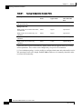
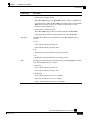
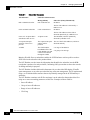
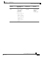
Table 2-1
Topology Configuration Summary Table
Description
Connection
mode
On-failure link
bypass mode
Admin status
after abnormal
boot
Link connection via external switch
with port-mirroring
Receive-only
Bypass
Operational
Bump-in-the-wire, monitor and control,
not redundant
Inline
Bypass
Operational
Bump-in-the-wire, monitor only, not
redundant
Inline
Bypass
Operational
Bump-in-the-wire, monitor and control,
redundant
Inline
Cutoff
Operational[1]
Bump-in-the-wire, monitor only,
redundant
Inline
Cutoff
Operational[1]
Bump-in-the-wire
* Italicized values represent automatically applied defaults that are applied based on previously
defined parameters. These values can be changed only via specific CLI commands.
[1]: In a redundant topology, it is also possible to configure admin status after abnormal boot to be
Not operational. In this case, though, the SCE 1000 would have to be manually reloaded in order
to resume full functionality.
SCE 1000 2xGBE Release 2.0.10 User Guide
2-10
OL-7117-02
CHAPTER 3
Command Line Interface
This chapter describes how to use the SCE 1000 Command Line Interface (CLI), its hierarchical
structure, authorization levels and its help features. The Command Line Interface (CLI) is one of
the SCE 1000 Platform management interfaces. The remainder of this manual describes how to
manage the SCE 1000 Platform using the Command Line Interface (CLI).
The CLI is accessed through a Telnet session or directly via the console port on the front panel of
the SCE 1000. When you enter a Telnet session, you enter as the simplest level of user, in the
User Exec mode.
The SCE 1000 supports up to six concurrent CLI sessions; five sessions initiated by Telnet
connection, and one session on the console port.
In this chapter and throughout the book, the procedures shown are examples of how to perform
typical SCE Platform management functions using the CLI. Because of the large number of
functions available, not every possible procedure is documented. For a complete listing of
available CLI commands for SCE 1000 administrators, see CLI Command Reference (on page A1). The various chapters throughout the manual give you examples of how to implement the most
common of these commands, as well as general information on the interrelationships between the
commands and the conceptual background of how to use them.
Step 3 This chapter contains the following sections:
• Authorization and Command Levels (Hierarchy) 3-1
• CLI Help Features 3-11
• Navigational and Shortcut Features
3-13
• CLI Scripts3-15
Authorization and Command Levels (Hierarchy)
When using the CLI there are two important concepts that you must understand in order to
navigate:
•
Authorization Level: Indicates the level of commands you can execute. A user with a simple
authorization level can only view some information in the system, while a higher level
administrator can actually make changes to configuration. Almost all of the procedures in this
manual require an Admin authorization level. See CLI Command Hierarchy.
SCE 1000 2xGBE Release 2.0.10 User Guide
OL-7117-02
3-1
Chapter 3
Command Line Interface
Authorization and Command Levels (Hierarchy)
•
Command Hierarchy Level: Provides you with a context for initiating commands.
Commands are broken down into categories and you can only execute each command within
the context of its category. For example, in order to configure parameters related to the Line
Card, you need to be within the LineCard Interface Configuration Mode. See CLI Command
Hierarchy.
The following sections describe the available Authorization and Command Hierarchy Levels and
how to maneuver within them.
The on-screen prompt indicates both your authorization level and your command hierarchy level,
as well as the assigned host name. See Prompt Indications (on page 3-10).
Note
Throughout the manual, SCE 1000 is used as the sample host name.
CLI Authorization Levels
The SCE 1000 system has three authorization levels, which represent the user’s access
permissions. When you initially connect to the SCE 1000, you automatically have the most basic
authorization level, that is User, which allows minimum functionality.
In order to perform administrative functions on the SCE 1000, you must have Admin or Root
authorization, which means changing the level by logging in with an Admin or Root password, as
described in the procedure “To log in with Admin level authorization,” below. This manual covers
the functions that can be performed by the Admin level user.
The commands available in each authorization level are all the commands of the lower
authorization layers plus commands that are authorized only to this level.
Note
This manual covers the functions that can be performed by the Admin level user, unless otherwise
noted.
The following CLI commands are related to authorization levels:
•
enable
•
disable
Each authorization level has a value (number) corresponding to it. When using the CLI
commands, use the values, not the name of the level, as shown in the following table.
SCE 1000 2xGBE Release 2.0.10 User Guide
3-2
OL-7117-02
Chapter 3
Command Line Interface
Authorization and Command Levels (Hierarchy)
Table 3-1
Authorization Levels
Level
Description
Value
Prompt
User
Password required. This level enables basic operational functionality. 0
>
Admin
Password required. For use by general administrators, the Admin
authorization level enables configuration and management of the
SCE 1000.
10
#
Root
Password required. For use by technical field engineers, the Root
authorization level enables configuration of all advanced settings,
such as debug and disaster recovery. The Root level is used by
technical engineers only and is not documented in this manual.
15
#>
A telnet session begins with a request for password, and will not continue until the proper user
password is supplied. This enhances the security of the system by not revealing its identity to
unauthorized people.
To log in with Admin level authorization:
Step 4 Initiate a telnet connection.
Step 5 A Password: prompt appears. Type in the user level password and press Enter.
The SCE 1000> prompt appears.
You now have user level authorization.
Step 6 From the SCE 1000> prompt, type enable 10 and press Enter.
The system prompts for a password by showing the prompt Password:
Step 7 Type in the password for the Admin level and press Enter.
Note that the password is an access-level authorization setting, not an individual user
password.
The system prompt changes to SCE 1000# to show you are now in Admin level.
EXAMPLE:
The following example illustrates how to change the authorization level from User to Admin, and
then revert back to User. No password is required for moving to a lower authorization level.
SCE 1000>enable 10
Password: cisco
SCE 1000#disable
SCE 1000>
SCE 1000 2xGBE Release 2.0.10 User Guide
OL-7117-02
3-3
Chapter 3
Command Line Interface
Authorization and Command Levels (Hierarchy)
CLI Command Hierarchy
The set of all CLI commands is grouped in hierarchical order, according to the type of the
commands. The first two levels in the hierarchy are the User Exec and the Privileged Exec modes.
These are non-configuration modes in which the set of available commands enables the
monitoring of the SCE 1000, file system operations, and other operations that cannot alter the
configuration of the SCE 1000.
The next levels in the hierarchy are the Global and Interface configuration modes, which hold a
set of commands that control the global configuration of the SCE 1000 and its interfaces. Any of
the parameters set by the commands in these modes should be saved in the startup configuration,
such that in the case of a reboot, the SCE 1000 restores the saved configuration.
The following table shows the available CLI modes.
Table 3-2
CLI Modes
Mode
Description
Level
Prompt indication
UserExec
Initial mode with very limited functionality.
User
SCE 1000>
Privileged Exec
General administration for monitoring, file
system manipulations and control of basic
parameters which do not change the
configuration of the SCE 1000.
Admin
SCE 1000#
Global
Configuration
Configuration of general system parameters,
such as DNS, host name, and time zone.
Admin
SCE 1000(config)#
Interface
configuration
Configuration of specific system interface
parameters, such as the Line Card, and the
FastEthernet interfaces.
Admin
SCE 1000(config
if)#
Line
Configuration
Configuration of Telnet lines, such as an
access-list.
Admin
SCE 1000(configline)#
SCE 1000 2xGBE Release 2.0.10 User Guide
3-4
OL-7117-02
Chapter 3
Command Line Interface
Authorization and Command Levels (Hierarchy)
When you login to the system, you have the User authorization level and enter User Exec mode.
Changing the authorization level to Admin automatically moves you to Privileged Exec mode. In
order to move to any of the configuration modes, you need to enter commands specific to that
mode.
The list of available commands in each mode can be viewed using the question mark ‘?’ at the end
of the prompt.
The following figure illustrates the hierarchical structure of the CLI modes, and the CLI
commands used to enter and exit a mode.
Figure 3-1: CLI Command Hierarchy
The following commands are used to enter the different configure interface modes and the Line
Configuration Mode:
E1
interface LineCard 0
E2
interface FastEthernet 0/0
E3
interface GigabitEthernet 0/1 or 0/2
E4
line vty 0 or 1 or 2 or 3 or 4
SCE 1000 2xGBE Release 2.0.10 User Guide
OL-7117-02
3-5
Chapter 3
Command Line Interface
Authorization and Command Levels (Hierarchy)
To move from one interface configuration mode to another you must exit the current interface
configuration mode (as illustrated in the above figure).
Note
Although the system supports up to five concurrent Telnet connections, you cannot configure them
separately. This means that any number you enter in the line vty command (0, 1, 2, 3 or 4) will act as
a 0 and configure all five connections together.
EXAMPLE:
This example illustrates moving into and out from Interface configuration mode as follows:
•
Configure the SCE 1000 time zone (global configuration)
•
Enter Interface configuration mode
•
Configure the speed of the management interface
•
Define the operational bypass mode.
•
Exit Interface configuration mode
SCE
SCE
SCE
SCE
SCE
SCE
SCE
SCE
1000#>configure
1000(config)#>clock timezone PST -10
1000(config)#>interface FastEthernet 0/0
1000(config if)#>speed 100
1000(config)#>exit
1000(config)#>interface LineCard 0
1000(config if)#>link-bypass on-operational no-bypass
1000(config if)#>exit
Entering and Exiting Global Configuration Mode
To enter the Global Configuration Mode:
Step 1 At the SCE 1000# prompt, type configure, and press Enter.
The SCE 1000(config)# prompt appears.
To exit the Global Configuration Mode:
Step 1 At the SCE 1000(config)# prompt, type exit and press Enter.
The SCE 1000# prompt appears.
Interface Configuration Modes
The interfaces that are configured by the Interface Configuration Modes are:
•
LineCard: Interface LineCard 0
SCE 1000 2xGBE Release 2.0.10 User Guide
3-6
OL-7117-02
Chapter 3
Command Line Interface
Authorization and Command Levels (Hierarchy)
The LineCard interface configures the main functionality of viewing and handling traffic on
the line.
•
Fast Ethernet Management: Interface FastEthernet 0/0
The FastEthernet Management Interface configures the settings for the interface to other
network elements within the system. This interface should be connected to the internal
Ethernet within the operator’s site.
•
Gigabit Ethernet Link: Interface GigabitEthernet 0/1 or 0/2
The GigabitEthernet Interface mode configures the settings for the GigabitEthernet interface
to the Internet traffic on the wire. Each of the two ports can be set individually.
•
Line Configuration Mode: Line vty 0
Line Configuration Mode enables you to configure Telnet parameters.
Configuring the Physical Network Interface Parameters
The SCE 1000 system contains the following network interfaces:
•
FastEthernet Management: Interface FastEthernet (0/0)
The FastEthernet Management Interface mode configures the settings for the interface other
network elements within the system. This interface should be connected to the internal
Ethernet within the operator site.
•
GigabitEthernet: Interface GigabitEthernet (0/1 or 0/2)
The GigabitEthernet Interface mode configures the settings for the GigabitEthernet interface
to the Internet traffic on the wire. Each of the two ports can be set individually.
Note
You must specify Slot number and Interface number when referencing the FastEthernet Interface or the
GigabitEthernet Interface. Slot number is always 0, and the interfaces are numbered as follows:
GigabitEthernet Line Interfaces: 1,2
FastEthernet Management Interface: 0
Entering FastEthernet (Management) Interface Configuration Mode
Before you can configure the FastEthernet parameters for the management interface, you must be
in the FastEthernet Management Interface Configuration Mode.
To enter FastEthernet Management Interface Configuration Mode:
Step 1 To enter Global Configuration Mode, type configure and press Enter.
The SCE 1000(config)# prompt appears.
Step 2 Type interface FastEthernet 0/0 and press Enter.
The SCE 1000(config if)# prompt appears.
The system prompt changes to reflect the higher level mode.
SCE 1000 2xGBE Release 2.0.10 User Guide
OL-7117-02
3-7
Chapter 3
Command Line Interface
Authorization and Command Levels (Hierarchy)
To return to the Global Configuration mode:
Step 1 Type exit.
Entering LineCard Interface Configuration Mode
The following procedure is for entering Line Card Interface Configuration mode. The procedures
for entering the other interfaces are the same except for the interface command as described above
and in CLI Command Reference (on page A-1).
To enter LineCard Interface Configuration mode:
Step 1 To enter Global Configuration Mode, at the SCE 1000# prompt, type configure, and
press Enter.
The SCE 1000(config)# prompt appears.
Step 2 Type interface LineCard 0, and press Enter.
The SCE 1000(config if)# prompt appears.
Step 3 To return to Global Configuration Mode, type exit and press Enter.
The SCE 1000(config)# prompt appears.
Step 4 To exit Global Configuration Mode, type exit and press Enter.
The SCE 1000# prompt appears.
Entering GigabitEthernet Line Interface Configuration Mode
To enter GigabitEthernet Interface Configuration Mode:
Step 1 To enter Global Configuration Mode, type configure and press Enter.
The SCE 1000(config)# prompt appears.
Step 2 Type interface GigaBitEthernet [0/1|0/2] and press Enter.
interface GigaBitEthernet 0/1 enables configuration of interface 1
interface GigaBitEthernet 0/2 enables configuration of interface 2
The SCE 1000(config if)# prompt appears.
SCE 1000 2xGBE Release 2.0.10 User Guide
3-8
OL-7117-02
Chapter 3
Command Line Interface
Authorization and Command Levels (Hierarchy)
EXAMPLE:
The following example shows how to enter Configuration Mode for the GigabitEthernet
Interface number 2.
SCE 1000(config)#interface GigabitEthernet 0/2
SCE 1000(config if)#
Navigating between the Interface Configuration Modes
To navigate from one Interface Configuration Mode to another:
Step 1 Type exit.
You are returned to the Global Configuration Mode.
Step 2 Type the appropriate command to enter a different Interface Configuration Mode.
Interface Configuration Modes
The interfaces that are configured by the Interface Configuration Modes are:
•
LineCard: Interface LineCard 0
The LineCard interface configures the main functionality of viewing and handling traffic on
the line.
•
Fast Ethernet Management: Interface FastEthernet 0/0
The FastEthernet Management Interface configures the settings for the interface to other
network elements within the system. This interface should be connected to the internal
Ethernet within the operator’s site.
•
Gigabit Ethernet: Interface GigabitEthernet 0/1, 0/2, 0/3, or 0/4
The GigabitEthernet Interface mode configures the settings for the GigabitEthernetinterface to
the Internet traffic on the wire. Each of the four ports can be set individually.
•
Line Configuration Mode: Line vty 0
Line Configuration Mode enables you to configure Telnet parameters.
Exiting Modes
This section describes how to revert to a previous mode. When you use the exit command you
revert to the general level above the current level, as shown in the figure in CLI Command
Hierarchy.
To exit from the Privileged Exec mode and revert to the User Exec mode:
Step 1 At the SCE 1000# prompt, type disable, and press Enter.
The SCE 1000> prompt for the User Exec mode appears.
SCE 1000 2xGBE Release 2.0.10 User Guide
OL-7117-02
3-9
Chapter 3
Command Line Interface
Authorization and Command Levels (Hierarchy)
Exiting from any configuration mode and revert to the previous mode is done in the same manner,
as in the following procedure.
To exit from the Global Configuration Mode:
Step 1 At the SCE 1000(config)# prompt, type exit, and press Enter.
The appropriate prompt for the previous level appears.
EXAMPLE:
The following example shows the system response when you exit the Interface Configuration
mode.
SCE 1000(config if)#exit
SCE 1000(config)#
Prompt Indications
The on-screen prompt indicates your authorization level, your command hierarchy level, and the
assigned host name. The structure of the prompt is:
<hostname(mode-indication)level-indication>
Authorization levels are indicated as follows:
This prompt...
Indicates this...
>
indicates User level
#
indicates Admin level
#>
indicates Root level
SCE 1000 2xGBE Release 2.0.10 User Guide
3-10
OL-7117-02
Chapter 3
Command Line Interface
CLI Help Features
Command hierarchy levels are indicated as follows:
This command hierarchy...
Is indicated as...
User Exec
SCE 1000>
Privileged Exec
SCE 1000#
Global Configuration
SCE 1000(config)#
Interface Configuration
SCE 1000(config if)#
Line Configuration
SCE 1000(config-line)#
EXAMPLE:
The prompt MySCE 1000(config if)# indicates:
•
The name of the SCE 1000 is MySCE 1000
•
The user has Admin authorization level
•
The current CLI mode is Interface configuration mode
CLI Help Features
CLI provides context sensitive help. Two types of context sensitive help are supported:
•
Partial help
•
Argument help
Partial Help
To obtain a list of commands that begin with a particular character string, enter the abbreviated
command entry immediately followed by a question mark (?). This form of help is called partial
help, because it lists only the keywords or arguments that begin with the abbreviation you entered.
EXAMPLE:
The following example illustrates how typing c? displays all available arguments that start with
the letter c.
SCE 1000(config)#snmp-server c?
Community
contact
SCE 1000(config)#snmp-server c
Argument Help
To obtain a list of command’s associated keywords or parameters, type a question mark (?) in
place of a keyword or parameter on the command line.
Note that if <Enter> is acceptable input, the symbol <cr> represents the Enter key.
SCE 1000 2xGBE Release 2.0.10 User Guide
OL-7117-02
3-11
Chapter 3
Command Line Interface
CLI Help Features
EXAMPLE:
The following example illustrates how to get a list of all arguments or keywords expected after
the command snmp-server.
SCE 1000(config)#snmp-server ?
Community
Define community string
Contact
Set system contact
Enable
Enable the SNMP agent
Host
Set traps destination
Location
Set system location
SCE 1000(config)#
When asking for help on particular parameter, the system informs you of the type of data that is
an accepted legal value. The types of parameters supported are:
STRING
When a String is expected, you can enter any set of characters or digits. If the string has a
space as one of its characters, use double-quote (“) marks to enclose the string.
DECIMAL
Any decimal number. Positive number is assumed, for negative numbers use the “–”
symbol.
HEX
A hexadecimal number; must start with either 0x or 0X.
EXAMPLE:
The following example illustrates the use of ? to get help on commands syntax. In this example,
you can enter either the word running-config, or any name of a file, after the word copy.
SCE 1000#copy ?
running-config
STRING
SCE 1000#
Copy running configuration file
Source file name
The [no] Prefix
Many CLI commands offer the option of adding the word no before the command to disable the
feature controlled by the command or revert it to its default configuration. This notation is shown
in the CLI Command Reference (on page A-1) as [no] to denote it is optional.
For example, no service telnetd disables the telnet server. Enabling the telnet server is
done by typing service telnetd.
SCE 1000 2xGBE Release 2.0.10 User Guide
3-12
OL-7117-02
Chapter 3
Command Line Interface
Navigational and Shortcut Features
Navigational and Shortcut Features
Command History
CLI maintains a history buffer of the most recent commands you used in the current CLI session
for quick retrieval. Using the keyboard, you can navigate through your last commands, one by
one, or all commands that start with a given prefix. By default, the system saves the last 30
commands you typed. You can change the number of commands remembered using the history
size command.
To use the history functions, use the keys shown in the following table.
Table 3-3
Keyboard Shortcuts for History Functions
Arrow
Shortcut
Description
Up arrow
Ctrl-P
Moves cursor to the previous command with the same prefix.
Down arrow
Ctrl-N
Moves cursor to the next command with the same prefix as original.
Ctrl-L
Ctrl-R
Re-display the current command line.
Keyboard Shortcuts
The SCE 1000 has a number of keyboard shortcuts that make it easier to navigate and use the
system. The following table shows the keyboard shortcuts available.
You can get a display the keyboard shortcuts at any time by typing help bindings.
Table 3-4
Keyboard Shortcuts
Shortcut Key
Description
Navigational shortcuts
CTRL-F /->
Move cursor one character to the right.
CTRL-B /<-
Move cursor one character to the left.
ESC-F
Move cursor one word to the right (forward).
ESC-B
Move cursor one word to the left (backward.
CTRL-A
Move cursor to the start of the line.
CTRL-E
Move cursor to the end of the line.
Editing shortcuts
CTRL-D
Delete the character where the cursor is located.
ESC-d
Delete from the cursor position to the end of the word.
Backspace
Delete the character before the current location of the cursor.
CTRL-H
Delete the character before the current location of the cursor.
CTRL-K
Deletes from the cursor position to the end of the line
CTRL-U
Deletes all characters from the cursor to the beginning of the line
SCE 1000 2xGBE Release 2.0.10 User Guide
OL-7117-02
3-13
Chapter 3
Command Line Interface
Navigational and Shortcut Features
Shortcut Key
Description
CTRL-X
Deletes all characters from the cursor to the beginning of the line. (Same
functionality as CTRL-U.)
CTRL-W
Delete the word to the left of the cursor.
CTRL-Y
Recall the last item deleted.
<Tab>
Completes the word when there is only one possible completion.
CTRL-I
Completes the word when there is only one possible completion. (Same
functionality as CTRL-I.)
Tab Completion
The CLI interface features tab completion. When you type in the first letters of a command and
type <Tab>, the system automatically fills in the rest of the command or keyword. This feature
works only when there is one possible command that could be possible using the starting letters.
EXAMPLE:
The letters snm followed by <Tab> will be completed to the command snmp-server.
SCE 1000(config)#snm<Tab>
SCE 1000(config)#snmp-server
If you type <Enter> instead of <Tab>, and there is no ambiguity, the system actually carries out
the command which would be filled in by the rest of the word.
EXAMPLE:
The following example displays how the system completes a partial (unique) command for the
enable command. Because enable does not require any parameters, the system simply carries
out the enable command when the user presses Enter.
SCE 1000>en<Enter>
Password:
SCE 1000#
FTP User Name and Password
CLI enables saving ftp user name and password to be used in FTP operations—download and
upload, per session.
These settings are effective during the current CLI session.
EXAMPLE:
The following example illustrates how to set FTP password and user name and the use in these
settings for getting a file named config.tmp from a remote station using FTP protocol.
SCE 1000#ip ftp password vk
SCE 1000#ip ftp username vk
SCE 1000#copy ftp://@10.1.1.253/h:/config.tmp myconf.txt
connecting 10.1.1.253 (user name vk password vk) to retrieve config.tmp
SCE 1000#
SCE 1000 2xGBE Release 2.0.10 User Guide
3-14
OL-7117-02
Chapter 3
Command Line Interface
CLI Scripts
CLI Scripts
The CLI scripts feature allows you to record several CLI commands together as a script and play
it back. This is useful for saving repeatable sequence of commands , such as software upgrade.
For example, if you are configuring a group of SCE 1000s and you want to run the same
configuration commands on each SCE 1000, you could create a script on one SCE 1000 and run it
on all the other SCE 1000s.
The available script commands are:
•
script capture
•
script stop
•
script print
•
script run
To create a script:
Step 1 At the SCE 1000# prompt, type script capture sample1.scr where
sample1.scr is the name of the script.
Step 2 Perform the actions you want to be included in the script.
Step 3 Type script stop.
The system saves the script.
EXAMPLE:
The following is an example of recording a script for upgrading software.
SCE 1000#script capture upgrade.scr
SCE 1000#configure
SCE 1000(config)#boot system new.pkg
Verifying package file...
Package file verified OK.
SCE 1000(config)#exit
SCE 1000#copy running-config startup-config
Writing general configuration file to temporary location...
Extracting files from ‘/tffs0/images/new.pkg’...
Verifying package file...
Package file verified OK.
Device ‘/tffs0/’ has 81154048 bytes free, 21447973 bytes are needed for
extraction, all is well.
Extracting files to temp locations...
Renaming temp files...
Extracted OK.
Backing-up general configuration file...
Copy temporary file to final location...
SCE 1000#script stop
SCE 1000#
To run the script recorded above, type:
SCE 1000#script run upgrade.scr
SCE 1000 2xGBE Release 2.0.10 User Guide
OL-7117-02
3-15
CHAPTER 4
Installation and Startup
This chapter guides you through the process of installing and starting the SCE 1000. The
installation process should be performed in the order described in this chapter.
For further information, see the following chapters:
•
Overview of the SCE 1000 platform installation in various topologies: Topology (on page 2-1)
•
CLI commands: CLI Command Reference (on page A-1)
•
For possible solutions if problems arise during the installation process: Troubleshooting (on
page 10-1)
Step 4 This chapter contains the following sections:
• Pre-Installation Requirements
4-1
• Installation 4-6
• Connecting to the Power Supply 4-13
• Front Panel4-19
• Powering up
4-23
• Connecting the Local Console
• System Configuration
4-24
4-26
• Connecting the FE Management Port
4-46
• Connecting the line ports to the network 4-48
• Loading and Activating a Service Control Application
4-55
• Final Tests 4-55
Pre-Installation Requirements
You should perform the following steps prior to installing the system.
Step 1: Unpacking
Unpack the SCE 1000 from its kit.
SCE 1000 2xGBE Release 2.0.10 User Guide
OL-7117-02
4-1
Chapter 4
Installation and Startup
Pre-Installation Requirements
Step 2: Checking Shipping Contents
After opening the SCE 1000, verify that all the parts on the packing list are included.
Packing List Parts
Check
(if present)
Item
SCE 1000 platform
For AC systems:
AC power supply cords
Fast Ethernet cable for connecting to the Management port
RS-232 serial cable (DB-9 to RJ-45) for connecting to a local terminal
Rack-mount bracket kit comprising:
• 2 mounting brackets for 19” rack
• 6 screws (Philips), 8-32 x 3/8” (for attaching the brackets to the SCE 1000 chassis)
• supporting mounting brackets for 19” rack
• 2 crossrail supports for 19” rack with front and back posts
Grounding kit comprising:
• Grounding cable
• 2 Hex nuts (#¼”)
• 2 spring washers (#¼”)
4 Rubber Feet (for tabletop installation)
Step 3: Preparing to Install
Prior to installation make sure that you’re equipped with the required tools and parts, and that the
site is ready/prepared. Consider the power and cabling requirements that must be in place at your
installation site, and the environmental conditions your installation site must meet in order to
maintain normal operation.
Tools and Parts Required
The SCE 1000 chassis is fully assembled at the factory; including the application and software
packages. No assembly is required. However, you need the following tools and equipment to
install the SCE 1000 chassis and the rack-mount and secure cable kit:
•
Number 1 and 2 Phillips screwdriver
•
#¼” Hex Wrench
•
19” Rack (for rack mounting), compatible with the dimensions of the SCE 1000, as described
in the table SCE 1000 Dimensions.
•
Screws compatible with your rack (for mounting the SCE 1000 to the rack)
•
Table top (free of dust, compatible with the SCE 1000 dimensions, for table-top mounting)
SCE 1000 2xGBE Release 2.0.10 User Guide
4-2
OL-7117-02
Chapter 4
Installation and Startup
Pre-Installation Requirements
SCE 1000 Dimensions
The dimensions of the SCE 1000 are displayed in the following figure. The following table, SCE
1000 Dimensions, contains the SCE 1000 dimension measurements.
Figure 4-1: SCE 1000 Dimensions
Table 4-1
SCE 1000 Dimensions
Dimension
Measurement
Height
3.47 inches (9.5 cm)
Width
17.4 inches (4.43 cm)
Depth
18 inches (4.6 cm)
Mounting options
19” rack and desktop mounting options
Weight
33 lb (15 kg)
Site Requirement Guidelines
Warning
It is recommended that you be fully familiar with all important safety information before working with
the SCE 1000 unit. See the chapter, Regulatory Compliance and Safety Information (on page xvii).
SCE 1000 2xGBE Release 2.0.10 User Guide
OL-7117-02
4-3
Chapter 4
Installation and Startup
Pre-Installation Requirements
The environmental monitoring functionality in the SCE 1000 protects the system and components
from potential damage from over-voltage and over-temperature conditions. To ensure normal
operation and to avoid unnecessary maintenance, plan your site configuration and prepare your
site before installation. After installation, make sure the site maintains an ambient temperature of
23oF (–5oC) through 131oF (55oC), and keep the area around the SCE 1000 chassis free from dust.
Planning a proper location for the SCE 1000 and the layout of your equipment rack or wiring
closet is essential for successful system operation. Equipment placed too close together or
inadequately ventilated can cause system over-heating. In addition, chassis panels made
inaccessible by poor equipment placement can make system maintenance difficult. The following
precautions can help avoid problems during installation and ongoing operation.
Airflow
Figure 4-2: Airflow Through the SCE 1000
When you plan the location and layout of your equipment rack or wiring closet you need to
consider how air flows though your system. The SCE 1000 draws cooling air in through the
intake vents on the left side of the chassis, moves the air across the internal components, and out
through the right side and rear panel of the chassis. The above figure illustrates the airflow
through the SCE 1000.
SCE 1000 2xGBE Release 2.0.10 User Guide
4-4
OL-7117-02
Chapter 4
Installation and Startup
Pre-Installation Requirements
Fans
The fan module provides cooling for the internal components. The fan drawer is a fieldreplaceable unit containing five fans, and is installed at the right rear of the SCE 1000.
Figure 4-3: SE2000 Fan Module
When you install the SCE 1000, ensure adequate airflow for the inlet and exhaust vents.
Note
Remember to leave a two inch (5 cm) clearance on both sides of the SCE 1000 and five inches (12.7
cm) at the rear for adequate airflow for the inlet and exhaust vents.
Site Requirements
The following tables contain the site requirement specifications for the SCE 1000.
Table 4-2
SCE 1000 AC Power supply
Power
Specification
AC power input
100 to 240 VAC
AC power frequency
47 to 63 Hz
Power consumption
up to 200W
SCE 1000 2xGBE Release 2.0.10 User Guide
OL-7117-02
4-5
Chapter 4
Installation and Startup
Installation
Table 4-3
SCE 1000 DC Power Supply
Power
Specification
DC power input
-36 to -72 V DC
Power consumption
up to 200W
Circuit breaker
One Fast 10A for each power supplier
Table 4-4
SCE 1000 Environmental Requirements
Environmental Factor
Requirement
Temperature -
23°F to 131°F (-5°C to +55°C)
Relative humidity
5% to 95% (non-condensing)
Table 4-5
SCE 1000 Approvals Specifications
Approval
Specification
EMC
• USA - According to standard CFR 47. FCC rules and regulations PART 15
Subpart B. Methods and procedures ANSI 63/4/1992
• European Community - According to generic EMISSIONS standard EN
50081-2. Methods and procedures EN 55022, .
• European Community - EN 50082-1 (ESD, RFI, EFT, etc.) (Commercial)
• International - CISPR22
Safety
Warning
UL60950, Full CE mark, EN60950
The SCE 1000 DC should be installed in a Restricted Access Location only.
Installation
This section provides instructions for the physical installation of the SCE 1000 platform,
including how to install the SCE 1000 in a rack, how to install the SCE 1000 on a tabletop or
workbench, how to attach cables, and how to connect the ground and electrical connections for
powering on the SCE 1000.
The SCE 1000 operates as either a tabletop or a rack-mounted unit. A rack-mounted kit is
included with the SCE 1000 when it is shipped from the factory. The kit provides the hardware
needed (see Packing List ("Packing List Parts" on page 4-2)) to mount the SCE 1000 in either of
two types of standard 19-inch equipment rack:
•
19-inch rack with only two posts in the front: Use the supporting brackets included in the kit
•
19-inch rack with only four posts, two in the front and two in the back: Use the crossrail
supports included in the kit
SCE 1000 2xGBE Release 2.0.10 User Guide
4-6
OL-7117-02
Chapter 4
Installation and Startup
Installation
If you are not rack-mounting your SCE 1000, place it on a sturdy tabletop or workbench. A rubber
feet kit is included for tabletop installations.
Installation Precautions
When installing the SCE 1000 on a workbench or tabletop or in a rack, ensure that the surface is
clean and in a safe location. Please observe the following conditions:
•
Allow at least 2 inches (5 cm) of clearance at its left and right sides for airflow clearance from
the inlet and exhaust vents, and that no exhaust air from other equipment is drawn into the
SCE 1000. See descriptions and illustrations regarding air flow, see Airflow (on page 4-4) and
Fans (on page 4-5).
•
Do not place the SCE 1000 on the floor during installation. Dust that accumulates on the floor
is drawn into the interior of the SCE 1000 by the cooling fans. Excessive dust inside the SCE
1000 can cause over-temperature conditions and component failures.
•
Allow at least 5 inches (12.7 cm) of clearance at the front and rear of the SCE 1000 for
installing and rudimentary maintenance for accessing network cables or equipment.
•
Ensure that the SCE 1000 will receive adequate ventilation. Do not install the SCE 1000 in an
enclosed cabinet where ventilation is inadequate!
•
Provide an adequate chassis Ground (earth) connection for the SCE 1000 (see Attaching a
Chassis Ground Connection (on page 4-15) for instructions).
Installing the SCE 1000 on a Workbench or Tabletop
You can install the SCE 1000 on any flat surface as long as the surface is large enough for the
SCE 1000 (see the table in SCE 1000 Dimensions (on page 4-3)), and allows for adequate air
flow/ventilation around the sides of the SCE 1000, as described in the Installation Precautions
(on page 4-7)).
Figure 4-4: Installing the System on a Flat Surface
SCE 1000 2xGBE Release 2.0.10 User Guide
OL-7117-02
4-7
Chapter 4
Installation and Startup
Installation
To install the SCE 1000 on a workbench or tabletop:
Step 1 Follow the installation precautions in Installation Precautions (on page 4-7).
Step 2 View the bottom panel by lifting the SCE 1000, placing your hands around the SCE
1000 sides and lifting the SCE 1000 from underneath. To prevent injury, avoid sudden
twists or moves.
There are four marked locations, indicating where to affix the rubber feet (see figure
above).
Step 3 Attach the rubber feet by removing the adhesive strips and affix the rubber feet onto the
marked locations (on the bottom panel).
Remember to check for proper ventilation. Allow at least 2 inches (5 cm) on each side
for proper ventilation and 5 inches (12.7 cm) at the back for ventilation.and power cord
clearance.
This completes the general workbench or tabletop installation.
Proceed to section, Connecting to the Power Supply to continue the installation.
Mounting the SCE 1000 in a Rack
You can mount the SCE 1000 to a 19” rack. There are two standard types of equipment racks, and
the appropriate brackets for each are provided in the enclosed kit.
•
19” rack with front rack posts: the mounting kit includes two mounting brackets
•
19” rack with front and back rack posts: in addition to the mounting brackets, the mounting
kit includes two crossrail supports that the unit slides onto
The SCE 1000 mounts to the two front rack posts with brackets that attach to the front of the SCE
1000 The inside width between the two posts or mounting strips (left and right) must be at least
17.3 inches (44 cm).
Note
Remember to leave a two-inch (5 cm) clearance on both sides of the SCE 1000 and at the rear for
adequate airflow for the inlet and exhaust vents.
Because the inlet and exhaust ports (vents) for cooling air are located at both sides of the chassis,
respectively, multiple SCE 1000s can be stacked in a rack with no vertical clearance.
SCE 1000 2xGBE Release 2.0.10 User Guide
4-8
OL-7117-02
Chapter 4
Installation and Startup
Installation
Step 1: Attaching the Brackets to the SCE 1000
Before installing the SCE 1000 in the rack, you must first install a rack-mount bracket on each
side of the front of the SCE 1000, as illustrated in the following figure. See Tools and Parts
Required (on page 4-2) for a listing of the parts and tools required for installing the rack–mount.
To install the rack-mount brackets on the SCE 1000 chassis:
Step 1 Align the rack-mount bracket to the side of the SCE 1000.
Step 2 Insert and tighten three screws.
Figure 4-5: Attaching the Mounting Brackets
Step 3 Repeat steps 1 and 2 on the other side of the SCE 1000.
This completes the steps for attaching the rack-mount brackets to the SCE 1000.
If mounting the SCE 1000 in a rack with only two posts, skip to Step 3: Mounting the
System to a Rack (on page 4-11).
If mounting the SCE 1000 in a rack with four posts, proceed to the next step to attach the
crossrail supports to the rack.
SCE 1000 2xGBE Release 2.0.10 User Guide
OL-7117-02
4-9
Chapter 4
Installation and Startup
Installation
Step 2: Attaching the Crossrail Supports to the Rack
When mounting in a rack with four posts (front and back) the two crossrail supports are mounted
one on each side of the rack. The SCE 1000 then slides into these crossrails, which support the
weight of the unit.
Note
Cisco recommends that you allow at least 1 or 2 inches (2.54 or 5.08 cm) of vertical clearance between
the SCE 1000 and any equipment directly above and below it.
To install the crossrail supports on a rack with both front and back posts:
Step 1 Assemble the two crossrail supports as illustrated below. Use three screws for each
crossrail assembly.
Make sure that they are oriented so that both crossrails will support the SCE 1000 when
they are attached to the rack.
Figure 4-6: Assembling the Slider Brackets
Step 2 Align the crossrail supports with the side of the rack, parallel to the floor.
Step 3 Insert and tighten two screws to the front posts or mounting strips of the rack
SCE 1000 2xGBE Release 2.0.10 User Guide
4-10
OL-7117-02
Chapter 4
Installation and Startup
Installation
Step 4 Insert and tighten two screws to the Back posts of the rack.
Figure 4-7: Attaching the Crossrails to the Rack
Step 5 Repeat steps 2 through 4 on the other side of the rack, keeping the brackets flush against
the posts and parallel to the supporting bracket on first side of the rack.
This completes the steps for attaching the rack-mount supporting brackets to the rack.
You are now ready to mount the SCE 1000 to the rack.
Step 3: Mounting the System to a Rack
When the appropriate mounting brackets are securely installed, the SCE 1000 can be installed
into the rack.
To mount the SCE 1000 to a rack:
Step 1 Make sure that your path to the rack is unobstructed. If the rack is on wheels, ensure that
the brakes are engaged or that the rack is otherwise stabilized.
Step 2 Position the SCE 1000 so that the front end is closest to you, and lift it carefully to place
it into the rack. To prevent injury, avoid sudden twists or moves.
Step 3 Slide the SCE 1000 into the rack, pushing it back until the brackets (installed at the front
of the SCE 1000) meet the mounting strips or posts on both sides of the rack.
SCE 1000 2xGBE Release 2.0.10 User Guide
OL-7117-02
4-11
Chapter 4
Installation and Startup
Installation
A rack with both front and back posts will have the crossrail supports installed. Slide the
SCE 1000 onto these crossrails and push it all the way back.
Figure 4-8: Sliding the SCE 1000 into the Rack
SCE 1000 2xGBE Release 2.0.10 User Guide
4-12
OL-7117-02
Chapter 4
Installation and Startup
Connecting to the Power Supply
Step 4 While keeping the brackets flush against the posts or mounting strips, align the holes in
the brackets with the holes on the rack or mounting strip.
Figure 4-9: Securing the SCE 1000 to a the Rack
Step 5 For each bracket, insert and tighten two appropriate screws to the rack.
Note
Since the brackets support the weight of the entire SCE 1000 chassis, be sure to use all four screws to
fasten the two rack-mount brackets to the rack posts.
This completes the procedure for installing the SCE 1000 in the rack. Proceed to the next
section, Connecting to the Power Supply, to continue the installation.
Connecting to the Power Supply
The SCE 1000 is available in two power options:
•
Dual line feed AC power: Unit comes with two appropriate AC power supply cords
•
Dual line feed DC power: requires appropriate cables (hex or loop connectors) (see
Connecting the DC Power Supply).
SCE 1000 2xGBE Release 2.0.10 User Guide
OL-7117-02
4-13
Chapter 4
Installation and Startup
Connecting to the Power Supply
Back Panel
The SCE 1000 back-panel consists of the field-replaceable power supply units with ON/OFF
switches, field-replaceable fan drawer, and ground connections, as shown in the following pair of
figures.
Figure 4-10: SCE 1000 Back Panel: AC Power
Figure 4-11: SCE 1000 Back Panel DC power
SCE 1000 2xGBE Release 2.0.10 User Guide
4-14
OL-7117-02
Chapter 4
Installation and Startup
Connecting to the Power Supply
Attaching a Chassis Ground Connection
Before you connect the power or turn on the power to the SCE 1000, Cisco strongly recommends
that you provide an adequate chassis Ground (protective earth) connection for the SCE 1000
chassis. A Chassis Grounding cable kit is provided with each SCE 1000.
Use the Ground wire kit to properly ground the SCE 1000 chassis (see Packing List ("Packing
List Parts" on page 4-2) for details).
To connect the grounding cable to the chassis grounding connector on the SCE 1000:
Step 1 From the enclosed Grounding kit, remove the necessary materials: the grounding cable
(green and yellow colored cable) and pairs of hex nuts and spring washers.
Step 2 On the Rear panel of the SCE 1000, locate the chassis grounding connector (refer to the
appropriate figure below).
Step 3 Attach the grounding cable (green and yellow colored cable), firmly fastening the
(enclosed) hex nuts and spring washers with a #¼” hex wrench (refer to the appropriate
figure below).
The grounding cable must be connected on the other side to the site equivalent of the AC
earth.
Figure 4-12: Grounding the Unit (AC)
SCE 1000 2xGBE Release 2.0.10 User Guide
OL-7117-02
4-15
Chapter 4
Installation and Startup
Connecting to the Power Supply
Figure 4-13: Grounding the Unit (DC)
SCE 1000 2xGBE Release 2.0.10 User Guide
4-16
OL-7117-02
Chapter 4
Installation and Startup
Connecting to the Power Supply
Connecting the AC Power Supply Cable
To connect the AC Power supply cable:
Step 1 Plug the AC power supply cable into the (AC) electrical inlet, located on the rear panel
of the SCE 1000.
Figure 4-14: Connecting the AC Power
Step 2 Plug the SCE 1000 AC power supply cable (attached on the SCE 1000 rear panel) into
an (AC) electrical outlet.
Step 3 Repeat the above steps for the second power cable.
You are now ready to turn the power on. For details, see Power Up ("Powering up" on
page 4-23).
SCE 1000 2xGBE Release 2.0.10 User Guide
OL-7117-02
4-17
Chapter 4
Installation and Startup
Connecting to the Power Supply
Connecting the DC Power Supply
To connect the DC power supply cables:
Step 1 Loosen the screws for the –48V and the –48V RTN connections, and attach the
appropriate cables (hex or loop connectors).
Figure 4-15: Connecting the DC Power
For specific instructions regarding grounding the unit, see Attaching a Chassis Ground
Connection (on page 4-15).
Step 2 Refasten the screws.
Step 3 Attach the DC cable to the DC power source through a fast 4A circuit breaker.
Step 4 Repeat the above steps for the second power cable.
The system powers on automatically.
SCE 1000 2xGBE Release 2.0.10 User Guide
4-18
OL-7117-02
Chapter 4
Installation and Startup
Front Panel
Front Panel
The SCE 1000 Front Panel consists of ports and LEDs as shown in the following figure and the
following two tables SCE 1000 Platform Posts and SCE 1000 LED Groups.
Figure 4-16: SCE 1000 Front Panel
SCE 1000 2xGBE Release 2.0.10 User Guide
OL-7117-02
4-19
Chapter 4
Installation and Startup
Front Panel
Table 4-6
SCE 1000 Ports
Port
Quantity
Description
Connect This Port To…
Mng1/
Mng2
2
10/100/1000 Ethernet RJ-45 ports for
management of the SCE 1000.
A LAN using an FE cable
with an RJ-45 connector
Mng 2 is currently not operational.
CLI designation: 0/0.
Console
1
RS-232 RJ-45 port for use by
technicians
AUX
1
RS-232 RJ-45 port used by technicians
GBE ports 1
&2
2
GigabitEthernet SC ports for connecting
to the link.
CLI designation: 0/1 and 0/2
Table 4-7
A local terminal (console)
using an RS-232 cable with
an RJ-45 connector, as
provided in the SCE 1000
kit.
Refer to Connecting the Line
Ports for cabling diagrams
for various topologies
SCE 1000 LED Groups
LED Groups
Description
Power A
• Continuous green: Power supply A is functioning normally
• Red: Power supply A present, but malfunctioning
• Unlit: Power supply A is either not present or has failed.
Power B
• Continuous green: Power supply B is functioning normally
• Red: Power supply B present, but malfunctioning
• Unlit: Power supply B is either not present or has failed.
Status
The Status LED indicates the operational status of the SCE 1000 system, as
follows:
• Unlit: indicates no power from either power unit.
• Orange: indicates that the system is booting up.
• Flashing green: indicates that the system is fully operational.
• Flashing orange: indicates that the system is operational, but is in a warning
state.
• Red: indicates that there is a problem or failure
Note that Alarms are hierarchical: Failure takes precedence over Warning, which
takes precedence over operational.
SCE 1000 2xGBE Release 2.0.10 User Guide
4-20
OL-7117-02
Chapter 4
Installation and Startup
Front Panel
LED Groups
Description
Bypass
• Continuous green: indicates that the traffic bypasses the SCE 1000 through an
internal electrical bypass module.
Single SCE 1000 topology: The SCE 1000 is either in bypass or sniffing mode
Cascaded topology: Either the SCE 1000 is forwarding traffic to the other SCE
1000, where it is being processed, or is simply in bypass mode, so traffic
through it is not being processed.
• Unlit: traffic is not being bypassed
Single SCE 1000 topology: indicates normal operation of the SCE 1000
Cascaded topology: indicates normal operation of the active SCE 1000
GBE ports
The GBE LEDs indicate the operational status of the SCE 1000 line ports, as
follows:
• Link
Green: indicates that the port link is up
Unlit: indicates that the port link is down
• Rx
Flashing Green: indicates that there are incoming packets
• Tx
Flashing Green: indicates that there are outgoing packets
Mng
The Mng port LEDs indicate the operational status of the SCE 1000 out-of-band
LAN-based management port, as follows:
• Link/Active
Green: indicates that the port link is up
Unlit: indicates that the port link is down
• 10/100/1000
Green: indicates that the port is set to 100 Mbps
Unlit: indicates that the port is set to 10 Mbps
Orange: iindicates that the port is set to 1000 Mbps
SCE 1000 2xGBE Release 2.0.10 User Guide
OL-7117-02
4-21
Chapter 4
Installation and Startup
Front Panel
The following table presents the fiber specifications. The SCE 1000 may be ordered with either
Multimode or Single Mode transceivers. The transceiver type is indicated on the front panel under
the ports. Note that both transceivers on any individual SCE 1000 are the same, either 850nm
Multimode OR 1310 Single Mode.
Table 4-8
Fiber Specifications
SCE Model
Transceiver
Transmit Power
Receive Power
Typical (Max.) Distance
SCE 1000
2xGBE MM
850nm
(multimode)
–9.5 to –4 dBm
–17 to 0 dBm
• 750m for 50µm Core
Diameter MMF
• 400m for 62.5µm Core
Diameter MMF
SCE 1000
2xGBE SM
1310nm FRP
laser Single
Mode
–9.5 to –3 dBm
–20 to 3 dBm
10 km for 9.0µm Core
Diameter SMF
The following table lists the operational status states of the SCE 1000. The Status LEDs on the
SCE 1000 Front Panel reflect the current SCE 1000 operational state. The operational status state
can be displayed using CLI command show system operation-status.
Table 4-9
SCE 1000 Operational Status States
State
Description
Status LED
Booting
Initial state after reset
Orange
Operational
SCE 1000 becomes operational after completing the
following process:
Flashing green
• Boot is completed
• Power self-tests are completed without failure
• Platform configuration is applied
Warning
SCE 1000 is fully operational (as above) but one of the
following occured:
Flashing orange
• Line ports (GBE ports) to the link are down
• Management port link is down
• Temperature raised above threshold
• Voltage not in required range
• FANs problem
• Power supply problem
• Insufficient space on the disk
Note: If the condition that caused the SCE 1000 to be in
Warning state is resolved (for example, link is up) the SCE
1000 reverts to Operational state.
SCE 1000 2xGBE Release 2.0.10 User Guide
4-22
OL-7117-02
Chapter 4
Installation and Startup
Powering up
State
Description
Status LED
Failure
System is in Failure state after Boot due to one of the
following conditions:
Red
• Power on test failure.
• Three abnormal reboots in less than 20 minutes
• Platform configured to enter Failure mode consequent to
failure-induced reboot (this is configurable using CLI
command).
Note: Depending on the cause of failure, the management
interface and the platform configuration may or may not be
active/available.
Powering up
To power up the SCE 1000:
Step 1 Turn the power switches ON.
The power switches are located on the SCE 1000 rear panel.
The SCE 1000 operates AC or DC power input. In addition, it is recommended that the
SCE 1000 be powered through a backup power source, such as a UPS (Uninterruptible
Power Supply.)
Step 2 Power LED(s) should be green if the power supplies are connected. Bypass LED should
be green while the SCE 1000 is on bypass and unlit when the bypass is turned off.
Step 3 Look at the Status LED to see that it is orange.
As explained in the table above, while booting, the Status LED is a constant orange. After a
successful boot, the Status LED is flashing green.
Note
It takes a several minutes for the SCE 1000 to boot and for the status LED to change from orange to
flashing orange or flashing green.
You are now ready to cable the SCE 1000. If you are installing a redundant solution with two
SCE 1000s, refer to the installation procedure in Installing a Cascaded System before proceeding
with the installation.
Warning
When working with two SCE 1000s with split-flow and redundancy, it is extremely important to follow
the specified installation procedure.
SCE 1000 2xGBE Release 2.0.10 User Guide
OL-7117-02
4-23
Chapter 4
Installation and Startup
Connecting the Local Console
Connecting the Local Console
Even if you will be managing the SCE 1000 from a remote location, you must first connect the
unit to a local console and configure the initial settings for the SCE 1000 to support remote
management. When the initial connection is established, the setup utility will run automatically,
prompting you to perform the initial system configuration.
Setting Up the Local Console
This section provides instructions for setting up your local terminal at your workstation, to enable
you to perform the initial system configuration of the SCE 1000 system using the setup utility.
Figure 4-17: Connecting to the Local Console
Make sure that the terminal configuration is as follows:
•
9600 baud
•
8 data bits
•
No Parity
•
1 stop bits
•
No flow control
SCE 1000 2xGBE Release 2.0.10 User Guide
4-24
OL-7117-02
Chapter 4
Installation and Startup
Connecting the Local Console
The above SCE 1000 port parameters are fixed and are not configurable.
To set up the local console:
Step 1 Plug the enclosed RS-232 serial cable into the CON port on the front panel of the SCE
1000.
Make sure that you push on the RJ-45 connector (attached to the RS-232 serial cable)
until you hear a “click”, which indicates that the connector is fully inserted and secured
in the receptacle. Gently pull on the plug to confirm whether the plug is locked into the
socket.
Step 2 Connect the other end of the serial cable (with an attached DB-9 connector) to the
VT100 compatible local (serial) terminal.
Step 3 Make sure the local terminal is configured as a VT-100 terminal, according to the fixed
SCE 1000 CON port parameters.
Step 4 Press Enter several times until the setup configuration dialog is entered.
--- System Configuration Dialog --At any point you may enter a question mark ‘?’ followed by ‘Enter’ for help.
Use ctrl-C to abort configuration dialog at any prompt.
Use ctrl-Z to jump to the end of the configuration dialog at any prompt.
Default settings are in square brackets ‘[]’.
Would you like to continue with the System Configuration Dialog? [yes/no]: y
Step 5 Type y and press Enter.
The system configuration dialog begins.
SCE 1000 2xGBE Release 2.0.10 User Guide
OL-7117-02
4-25
Chapter 4
Installation and Startup
System Configuration
System Configuration
Upon initial connection to the local terminal, as described above, the system configuration wizard
automatically runs to guide the user through the entire setup process. The wizard prompts for all
necessary parameters, displaying default values, where applicable. You may accept the default
values or define other values.
With the exception of the time settings, which take effect immediately when entered, the new
configuration is applied and saved only at the end of the dialog when approved by the user.
Therefore, if the setup dialog is aborted, no change takes place in the configuration, other than
time settings (if entered).
When the dialog is complete, you may review the new configuration before applying it. The
system displays the configuration, including parameters that were not changed. The system also
displays any errors that are detected in the configuration. When the configuration is satisfactory,
you may apply and save the new configuration.
The following table lists all the parameter values that are necessary to complete the initial
configuration. It is recommended that you obtain all these values before beginning the setup.
Setup Command Parameters
Table 4-10
Setup Command Parameters
Parameter
Definition
IP address
IP address of the SCE 1000.
subnet mask
Subnet mask of the SCE 1000.
default gateway
Default gateway.
hostname
Character string used to identify the SCE 1000
admin password
Admin level password.
Character string from 4-100 characters beginning with an alpha character.
root password
Root level password.
Character string from 4-100 characters beginning with an alpha character.
password encryption
status
Enable or disable password encryption?
Time Settings
time zone name and
offset
Standard time zone abbreviation and minutes offset from UTC.
local time and date
Current local time and date. Use the format:
00:00:00 1 January 2002
SNTP Configuration
broadcast client status
Set the status of the SNTP broadcast client.
If enabled, the SCE will synchronize its local time with updates received
from SNTP broadcast servers.
SCE 1000 2xGBE Release 2.0.10 User Guide
4-26
OL-7117-02
Chapter 4
Installation and Startup
System Configuration
Parameter
Definition
unicast query interval
Interval in seconds between unicast requests for update (64 – 1024)
unicast server IP address
IP address of the SNTP unicast server.
DNS Configuration
DNS lookup status
Enable or disable IP DNS-based hostname translation.
default domain name
Default domain name to be used for completing unqualified host names
IP address
IP address of domain name server. ( maximum of 3 servers)
RDR Formatter Destination Configuration
IP address
IP address of the RDR-formatter destination
TCP port number
TCP port number of the RDR-formatter destination
Access Control Lists
Access Control List
number
How many ACLs will be necessary? What IP addresses will be
permitted/denied access for each management interface? You may want
ACLs for the following :
• Any IP access
• Telnet access
• SNMP GET access
• SNMP SET access
list entries (maximum 20
per list)
IP address, and whether permitted or denied access.
IP access ACL
ID number of the ACL controlling IP access.
telnet ACL
ID number of the ACL controlling telnet access.
SNMP Configuration
SNMP agent status
Enable or disable SNMP management.
GET community names
Community strings to allow GET access and associated ACLs (maximum
20).
SET community names
Community strings to allow SET access and associated ACLs (maximum
20).
trap managers
Trap manager IP address, community string, and SNMP version.
(maximum 20)
Authentication Failure
trap status
Set the status of the Authentication Failure trap. (See Traps (on page 634).)
enterprise traps status
Set the status of the enterprise traps. (See Traps (on page 6-34).)
system administrator
Name of the system administrator.
Topology Configuration
connection mode
Is the SCE 1000 installed in bump-in-the-wire topology (inline) or out of
line using a switch with port mirroring (receive-only)?
link bypass mode on
operational status
When the SCE 1000 is operational, should it bypass traffic or not?
Refer, in setup, to the table Setup Command Parameters.
SCE 1000 2xGBE Release 2.0.10 User Guide
OL-7117-02
4-27
Chapter 4
Installation and Startup
System Configuration
Parameter
Definition
redundant SCE 1000
platform?
Is there a redundant SCE 1000 installed as a backup?
link bypass mode on
non-operational status
When the SCE 1000 is not operational, should it bypass traffic or cut it
off?
Refer, in setup, to the table Setup Command Parameters.
operational status of the
SCE after abnormal boot
After a reboot due to a failure, should the SCE 1000 remain in a Failure
status or move to operational status provided no other problem was
detected?
Refer, in setup, to the table Setup Command Parameters.
Following are some general instructions regarding the setup dialog:
•
All default values appear in square brackets [default].
If no value appears in the brackets [], or more than one option appears [yes/no], then this
parameter does not have a default value.
•
To accept the default value, press Enter.
•
If you need more information about any parameter, type ? and press Enter.
A help message will appear describing the expected format of the parameter and any other
requirements.
•
To jump to the end of the setup dialog at any point, accepting all remaining default values,
press ctrl-z.
•
In certain cases, there will be two or more logically related parameters within a menu. In these
situations, it is not permitted to jump to the end of the setup dialog until all related parameters
are configured. If you try to jump to the end of the setup dialog, the following message will
appear: “Sorry, Skipping is not allowed at this stage.”
•
Certain groups of related parameters, such as time, date, and SNTP settings, form sub-dialogs
or menus within the setup dialog. You may skip an entire menu, thereby accepting all default
values for the parameters within the menu.
Each group of related parameters is prefaced by a question, asking whether you want to enter
the menu. To skip the menu, answer no (“n”) to the question.
EXAMPLE:
Would you like to enter the SNMP configuration menu? n
•
To abort the setup dialog at any point without making any configuration changes, press ctrl-c.
All changes already entered will be lost, with the exception of time settings.
Step 1: Configuring Initial Settings
Verify the following initial settings for the SCE 1000:
•
IP address
•
Subnet mask
•
Default gateway
SCE 1000 2xGBE Release 2.0.10 User Guide
4-28
OL-7117-02
Chapter 4
Installation and Startup
System Configuration
All values are Internet addresses of the form ‘X.X.X.X’, where each letter corresponds to a
decimal number between 0 and 255.
To configure the initial settings:
Step 1 The current IP address is displayed.
•
To accept the displayed value, press Enter.
•
To change the value, type the desired value in the format “x.x.x.x” and press Enter.
Step 2 The current subnet mask is displayed.
•
To accept the displayed value, press Enter.
•
To change the value, type the desired value in the format “x.x.x.x” and press Enter.
Step 3 The current IP address of the default gateway is displayed.
•
To accept the displayed value, press Enter.
•
To change the value, type the desired value in the format “x.x.x.x” and press Enter.
EXAMPLE:
The following example displays a typical configuration of the IP address (10.1.5.109), subnet
mask (255.255.0.0), and default gateway (10.1.1.3).
Since the IP address and the subnet mask are related, when the IP address is changed, there is no
longer a default value of the subnet mask, and it must be entered explicitly.
Enter IP address [10.1.1.201]:10.1.5.109
Enter IP subnet mask:255.255.0.0
Enter IP address of default gateway [10.1.1.3]:
Step 2: Configuring the Hostname
The hostname is used to identify the SCE 1000. It appears as part of the CLI prompt and is also
returned as the value of the MIB-II object sysName.
The default hostname is SCE 1000.
To configure the hostname:
Step 1 The current hostname is displayed.
•
To accept the displayed value, press Enter.
•
To change the value, type any desired character string and press Enter.
Enter hostname [SCE 1000]:
SCE 1000 2xGBE Release 2.0.10 User Guide
OL-7117-02
4-29
Chapter 4
Installation and Startup
System Configuration
Step 3: Setting the Passwords
Configure the passwords as follows:
Note
•
Set the password for each authorization level (User, Admin, Root).
•
Enable/disable password encryption. When password encryption is enabled, it encrypts the
previously entered passwords.
Passwords are needed for all authorization levels in order to prevent unauthorized users from accessing
the SCE 1000. Admin level should be used by the network administrator. Root level is for use by Cisco
technician.
Passwords must meet the following criteria:
•
Minimum length: 4 characters
•
Maximum length: 100 characters
•
Begin with an alpha character
•
May contain only printable characters
Note
Passwords are case sensitive.
Note
The default password for all levels is “cisco”.
To change the passwords:
Step 1 The default User password is displayed.
•
To accept the displayed value, press Enter.
•
To change the value, type the desired string and press Enter.
Step 2 The default Admin password is displayed.
•
To accept the displayed value, press Enter.
•
To change the value, type the desired string and press Enter.
Step 3 The default Root password is displayed.
•
To accept the displayed value, press Enter.
•
To change the value, type the desired string and press Enter.
Step 4 Configure password encryption. By default, password encryption is not enabled.
•
To disable password encryption, press Enter.
SCE 1000 2xGBE Release 2.0.10 User Guide
4-30
OL-7117-02
Chapter 4
Installation and Startup
System Configuration
•
To enable password encryption, type y and press Enter.
EXAMPLE:
Following is an example of changing all passwords. Password encryption is not enabled (default).
Enter a User password [cisco]: userin
Enter an Admin password [cisco]: mng123
Enter a Root password [cisco]: cistech
Enable passwords encryption? [no]:
Step 4: Configuring Time Settings
The time settings menu configures all time and date related parameters in the system. The time
settings menu includes the following:
•
Time zone
•
Local time
•
Date
•
SNTP menu
You must enter the time setting menu in order to configure SNTP settings. You may choose to
skip the time settings menu if you wish to accept all default values.
Note
Unlike all other settings defined in the system configuration, setting the time is done immediately and
not at the end of the setup process.
For more information on clocks and time zones, see Time Clocks and Time Zone (on page 6-11).
For more information on SNTP, see SNTP (on page 6-13).
To configure the time settings:
Step 1 Enter the time settings menu.
Would you like to enter the Time settings menu? [no]: y
Type y and press Enter.
The time settings dialog begins.
Step 2 Type the time zone abbreviation and press Enter.
Enter time zone name [UTC]: CET
Step 3 Type the minutes offset from UTC and press Enter.
Enter time zone minutes offset from UTC: 60
The local time and date are displayed, and you are asked whether you want to change
them.
The local time and date is 15:00:01 CET FRI 01 July 2002
Would you like to set a new time and date? [no]:
Step 4 If the time and date are correct, go to step 5.
SCE 1000 2xGBE Release 2.0.10 User Guide
OL-7117-02
4-31
Chapter 4
Installation and Startup
System Configuration
If the time and date are not correct, answer yes to the above question, and press Enter.
Would you like to set a new time and date? [no]: y
Confirm your response and type the new time and date.
This change will take effect immediately both on the system clock and the
calendar; it will also set the time zone you entered. Are you sure?
[yes/no]: y
Enter new local time and date: 14:00:01 1 July 2002
Time zone was successfully set.
The system clock and the calendar were successfully set.
Step 5 You are asked whether you wish to enter the SNTP configuration menu.
If you do not wish to configure the SNTP, skip the rest of this section and go to Step 5:
Configuring the DNS Settings (on page 4-33).
To enter the SNTP configuration dialog, type y, and press Enter
Would you like to enter the SNTP configuration menu? [no]: y
Step 6 Configure the SNTP broadcast client. By default the SNTP broadcast client is not
enabled.
•
To disable the SNTP broadcast client, press Enter.
•
To enable the SNTP broadcast client, type y and press Enter.
Enable SNTP broadcast client? [no]:
Step 7 Define the time interval between unicast updates.
•
To accept the displayed default value, press Enter.
•
To change the value, type the desired number of seconds (64 through 1024) and press
Enter.
Enter time interval in seconds between unicast updates [1024]:
Step 8 You may enter an IP address for the SNTP unicast server. Type in the hostname or the IP
address in the form x.x.x.x, and press Enter
Would you like to configure SNTP unicast servers? [no]: y
Enter IP address or hostname of SNTP unicast server: 10.1.1.1
SCE 1000 2xGBE Release 2.0.10 User Guide
4-32
OL-7117-02
Chapter 4
Installation and Startup
System Configuration
EXAMPLE:
Following is a sample time setting dialog. In addition to setting the time zone, time and date are
changed, and SNTP unicast updates are configured.
Would you like to enter the Time settings menu? [no]: y
Enter time zone name [UTC]: ISR
Enter time zone minutes offset from UTC: 120
The local time and date is 15:35:23 ISR FRI July 19 2002
Would you like to set a new time and date? [no]: y
This change will take effect immediately both on the system clock and the
calendar; it will also set the time zone you entered. Are you sure?
[yes/no]: y
Enter new local time and date: 14:35:23 19 July 2002
Time zone was successfully set.
The system clock and the calendar were successfully set.
Would you like to enter the SNTP configuration menu? [no]: y
Enable SNTP broadcast client? [no]: y
Enter time interval in seconds between unicast updates [900]:
Would you like to configure SNTP unicast servers? [no]: y
Enter IP address or hostname of SNTP unicast server: 10.1.1.1
Step 5: Configuring the DNS Settings
The DNS configuration menu defines the IP address(es) of the domain name server(s), which is
used for DNS lookup, as well as the default domain name, which is used to complete unqualified
host names.
You may choose to skip the DNS configuration menu if you wish to accept all default values.
To configure DNS settings:
Step 1 Enter the DNS settings menu.
Would you like to enter the DNS configuration menu? [no]: y
Type y and press Enter.
The DNS settings dialog begins.
Step 2 Enable or disable DNS lookup.
•
To enable DNS lookup, press Enter.
•
To disable DNS lookup, type n and press Enter.
Enable IP DNS-based hostname translation? [yes]:
If you choose to disable DNS lookup, skip the rest of this section and go to Step 6:
Configuring the RDR Formatter Destination (on page 4-34). The rest of the dialog is not
presented, as it is irrelevant when DNS lookup is disabled.
Step 3 Type the default domain name to be used, and press Enter.
Note that there is no default domain name.
You may accept the default domain name or enter a new one.
Enter default domain name []:
Step 4 Type the IP address of the primary domain name server and press Enter.
Enter Primary DNS IP address:
Note that there is no default for this parameter.
SCE 1000 2xGBE Release 2.0.10 User Guide
OL-7117-02
4-33
Chapter 4
Installation and Startup
System Configuration
Step 5 You may configure up to three domain servers.
Would you like to add another Name Server? [no]:
•
To exit the DNS settings dialog, press Enter.
•
To add another domain server, type y and press Enter.
You are asked to enter the IP address of the next domain name server.
Enter Secondary DNS IP address:
Step 6 When IP addresses for all servers have been entered, exit the dialog by pressing Enter.
Would you like to add another Name Server? [no]:
EXAMPLE:
Following is a sample DNS configuration dialog. The default domain name is pcube.com, and the
IP address of the Domain Name Server is 10.1.1.230.
Would you like to enter the DNS configuration menu? [no]: y
Enable IP DNS-based hostname translation? [yes]:
Enter default domain name []: pcube.com
Enter Primary DNS IP address: 10.1.1.230
Would you like to add another Name Server? [no]:
Step 6: Configuring the RDR Formatter Destination
The SCE 1000 passes Raw Data Records (RDRs) to an external collection system via the RDRFormatter. In order for the data to reach the correct location, the IP address of the external
collection system and its port number must be configured. See also RDR Formatter (RDR
Formatter "The RDR Formatter" on page 6-19).
To configure the RDR-formatter destination:
Step 1 Enter the RDR formatter configuration menu.
Would you like to enter the RDR-formatter configuration menu? [no]: y
Type y and press Enter.
The RDR-formatter destination dialog begins.
Step 2 Type the IP address of the RDR-formatter destination and press Enter.
Enter RDR-formatter destination’s IP address:
Note that there is no default for this parameter.
Step 3 Type the TCP port number of the RDR-formatter destination and press Enter.
Note that there is no default for this parameter.
Enter RDR-formatter destination’s TCP port number:
SCE 1000 2xGBE Release 2.0.10 User Guide
4-34
OL-7117-02
Chapter 4
Installation and Startup
System Configuration
EXAMPLE:
Following is a sample RDR-formatter configuration dialog, assigning the IP address and TCP port
number.
Would you like to enter the RDR-formatter configuration menu? [no]: y
Enter RDR-formatter destination’s IP address: 10.1.1.230
Enter RDR-formatter destination’s TCP port number: 33000
Step 7: Configuring Access Control Lists (ACLs)
The SCE 1000 can be configured with Access Control Lists (ACLs), which are used to permit or
deny incoming connections on any of the management interfaces.
Note
ACL #0 is a pre-defined list that permits access to all IP addresses.
Configuration of access control lists is done in two stages:
Step 1 Create the access control lists.
You may create 99 ACLs with a maximum of 20 entries per list. Each entry consists of
an IP address, and an indication of whether access is permitted or denied to this IP
address.
Step 2 Assign the ACLs to the appropriate management interface. (See Step 9: Configuring the
Topology-Dependent Parameters (on page 4-41).)
The dialog permits you to skip the creation/editing of the ACLs and go directly to
assigning ACLs to the management interfaces.
Entry Formats
Each ACL may permit/deny access to any IP address, one or more ranges of IP addresses, or one
or more individual IP address. Three entry formats are available to support these options:
•
Any IP address: Type the word “any”. Any IP address will be permitted or denied access.
•
Range of IP addresses: Type the beginning IP address in the desired range, then enter the
wildcard bits that define the range.
This wildcard functions like a reverse mask, in that all “1” bits in the wildcard indicate the
corresponding bit in the IP address should be ignored. All other bits must match the
corresponding bit in the specified IP address. Refer to the table below for examples.
Each range of IP addresses can be configured to be permitted or denied access.
•
Individual IP address: Type the desired IP address, then enter the wildcard bits 0.0.0.0.
Each individual IP address can be configured to be permitted or denied access.
SCE 1000 2xGBE Release 2.0.10 User Guide
OL-7117-02
4-35
Chapter 4
Installation and Startup
System Configuration
Table 4-11
IP address/Wildcard bit examples
Initial IP address
Wildcard bits
Range
10.1.1.0
0.0.0.255
10.1.1.0–10.1.1.255
10.1.1.0
0.0.0.63
10.1.1.0–10.1.1.63
10.1.1.0
0.0.0.0
10.1.1.0 (individual entry)
Order of Entries
The order of the entries in the list is important. The entries in the list are tested sequentially, and
the action is determined by the first entry that matches the connecting IP address. Therefore, when
the entry “any” appears in an Access Control List, all succeeding entries are irrelevant.
Consider two hypothetical ACLs containing the same entries in a different order.
The following list would permit access to all IP addresses, including 10.1.1.0:
permit any
deny 10.1.1.0
Note that the above list could not actually be created using the setup utility, since after the “any”
entry, no other entries could be added to the list.
The following list will deny access to IP address 10.1.1.0, but permit access to all others:
deny 10.1.1.0
permit any
If no entry in the assigned Access Control List matches the connection, or if the Access Control
List is empty, the default action is deny.
For a full explanation of how access control lists work, see Configuring Access Control Lists
(ACLs) (on page 6-2).
To create the access control lists:
Step 1 Enter the Access Control Lists configuration menu.
Would you like to enter the Access lists configuration menu? [no]: y
Type y and press Enter.
The Access Control Lists configuration dialog begins.
Step 2 You have the option of creating or modifying Access Control Lists, or skipping this
section and proceeding directly to assign the existing ACLs to the desired management
interfaces.
Would you like create new Access lists or modify existing lists? [no]: y
If you choose not to create or edit Access Control Lists, skip to Step 9: Configuring the
Topology-Dependent Parameters (on page 4-41).
Step 3 Type the number of the Access Control List to be configured (1 through 99) and press
Enter.
Note that there is no default for this parameter.
SCE 1000 2xGBE Release 2.0.10 User Guide
4-36
OL-7117-02
Chapter 4
Installation and Startup
System Configuration
Step 4 Begin adding entries to the selected list.
Indicate whether this entry is permitted access or denied access.
•
To permit access press Enter.
•
To deny access type n and press Enter.
Does this entry permit access? [yes]:
Step 5 Type the IP address to be added to this list, and press Enter.
Type “any” and press Enter to include any IP address in the ACL.
Note that there is no default for this parameter.
Enter IP address or the word ‘any’ to denote any IP address:
Step 6 If you entered a specific IP address, enter the wildcard bits to define a range of IP
addresses and press Enter. (See Entry Formats (on page 4-35).)
To define an individual IP address, type 0.0.0.0 and press Enter.
There is no default for this parameter.
Enter wildcard bits:
Step 7 The maximum number of entries in an ACL is 20.
If the “any” option was used, no other IP addresses may be added to the list.
•
To add more entries, type y and press Enter
Would you like to add another entry to this list? [no]:y
Enter up to 20 entries as described in step 5 and step 6.
•
When all entries have been added, press Enter
Would you like to add another entry to this list? [no]:
Step 8 When all entries are added to one list, you are asked whether you would like to create
another ACL. You may define up to 99 ACLs.
•
To create another ACL, type y and press Enter
Would you like to configure another list? [no]: y
Enter up to 20 IP addresses in this new ACL, as described in step 5 and step 6.
•
When all ACLs have been created, press Enter.
Would you like to configure another list? [no]:
You are now prompted to assign the desired ACLs to restrict IP and Telnet access.
Step 9 Restrict IP access to the SCE 1000 by assigning the appropriate ACL.
Type the number of the ACL to be assigned to IP access and press Enter.
To accept the default ACL, press Enter.
Enter IP access-class [0]:
Step 10 Restrict Telnet access to the SCE 1000 by assigning the appropriate ACL.
Type the number of the ACL to be assigned to the Telnet interface and press Enter.
To accept the default ACL, press Enter.
Enter Telnet access-class [0]: 2
SCE 1000 2xGBE Release 2.0.10 User Guide
OL-7117-02
4-37
Chapter 4
Installation and Startup
System Configuration
EXAMPLE:
This example illustrates a common access control scenario. Let us assume the following:
•
We want to permit every station to access the SCE on the management port (e.g. ping, SNMP
polling etc.).
•
We want to restrict Telnet access to only a few permitted stations.
We therefore need to create two access control lists:
•
For general IP access: permit access to all IP addresses.
•
For Telnet: permit access to the specified IP address, and deny to all others.
ACL #1 = permit any IP address. Assign to IP access.
ACL #2 = permit access to 10.1.1.0, 10.10.10.1, deny to all others. Assign to Telnet access.
Would you like to enter the Access lists configuration menu? [no]: y
Would you like create new Access lists or modify existing lists? [no]: y
Enter ACL number: 1
Does this entry permit access? [yes]:
Enter IP address or the word ‘any’ to denote any IP address: any
This entry matches every IP address, no use in adding more entries to this
list.
Would you like to configure another list? [no]: y
Enter ACL number: 2
Does this entry permit access? [yes]:
Enter IP address or the word ‘any’ to denote any IP address: 10.1.1.0
Enter wildcard bits: 0.0.0.0
Would you like to add another entry to this list? [no]:y
Does this entry permit access? [yes]:
Enter IP address or the word ‘any’ to denote any IP address: 10.10.10.1
Enter wildcard bits: 0.0.0.0
Would you like to add another entry to this list? [no]:y
Does this entry permit access? [yes]:n
Enter IP address or the word ‘any’ to denote any IP address: any
This entry matches every IP address, no use in adding more entries to this
list.
Would you like to configure another list? [no]:
Enter IP access-class [0]: 1
Enter Telnet access-class [0]: 2
EXAMPLE 2:
This example skips the first section of the dialog (creating/modifying), and proceeds directly to
assign existing ACLs.
Would
Would
Enter
Enter
you like to enter the Access lists configuration menu? [no]: y
you like create new Access lists or modify existing lists? [no]:
IP access-class [0]: 10
Telnet access-class [0]: 22
Step 8: Configuring SNMP
Managing the SCE 1000 is possible also via a Network Management System (NMS) that supports
SNMP. By default, SNMP is disabled on the SCE 1000. (See SNMP Configuration and
Management (on page 6-31) for further information.)
To enable SNMP management you must configure the following basic SNMP parameters:
•
SNMP traps status and managers.
SCE 1000 2xGBE Release 2.0.10 User Guide
4-38
OL-7117-02
Chapter 4
Installation and Startup
System Configuration
•
Community strings (where an SNMP community string is a text string that acts like a
password to permit access to the SNMP agent on the SCE 1000).
To configure SNMP parameters:
Step 1 Enter the SNMP configuration menu.
Would you like to enter the SNMP configuration menu? [no]: y
Type y and press Enter.
The SNMP configuration dialog begins.
Step 2 Enable SNMP management.
Type y and press Enter.
Enable SNMP management? [no]: y
If you choose to disable SNMP management, skip the rest of this section and go to Step
9: Configuring the Topology-Dependent Parameters (on page 4-41). The rest of the
dialog is not presented, as it is irrelevant when SNMP management is disabled.
Step 3 Type the SNMP GET community name and press Enter.
The SNMP agent that resides inside the SCE 1000 will respond only to GET requests
that use this community string.
Enter SNMP GET community name:
Note that there is no default for this parameter.
Step 4 Assign an access list to restrict the SNMP management stations that may use this GET
community.
Type a number (1 through 99) or type “0” to permit access to all IP addresses, and press
Enter.
Enter Access list number allowing access with this community string, use ‘0’
to allow all:
Step 5 The maximum number of GET communities is 20.
•
To add more entries, type y and press Enter
•
Would you like to add another SNMP GET community? [no]:y
Enter up to 20 SNMP GET communities as described in step 3 and step 4.
•
When all entries have been added, press Enter
Would you like to add another SNMP GET community? [no]:
Step 6 Type the SNMP SET community name and press Enter.
The SNMP agent that resides inside the SCE 1000 will respond only to SET requests that
use this community string.
Enter SNMP SET community name:
Note that there is no default for this parameter.
Step 7 Assign an access list to restrict the SNMP management stations that may use this SET
community.
Type a number (1 through 99) or type “0” to permit access to all IP addresses, and press
Enter.
SCE 1000 2xGBE Release 2.0.10 User Guide
OL-7117-02
4-39
Chapter 4
Installation and Startup
System Configuration
Enter Access list number allowing access with this community string, use ‘0’
to allow all:
Step 8 The maximum number of SET communities is 20.
•
To add more entries, type y and press Enter
Would you like to add another SNMP SET community? [no]:y
Enter up to 20 SNMP SET communities as described in step 6 and step 7.
•
When all entries have been added, press Enter
Would you like to add another SNMP SET community? [no]:
Step 9 Enter the SNMP trap managers menu.
Would you like to configure SNMP trap managers? [no]: y
Type y and press Enter.
The SNMP trap managers dialog begins.
If you choose not to configure SNMP trap managers, the dialog skips to the
authentication failure trap status. (See step 14.)
Step 10 Type the trap manager IP address and press Enter.
Enter SNMP trap manager IP address:
Note that there is no default for this parameter.
Step 11 Type the trap manager community string and press Enter.
Note that there is no default for this parameter.
Enter SNMP trap manager community string:
Step 12 Type the number of the trap manager SNMP version (1 or 2c) and press Enter
Note that there is no default for this parameter.
Enter trap manager SNMP version:
Step 13 The maximum number of trap managers is 20.
•
To add more entries, type y and press Enter
Would you like to add another SNMP trap manager? [no]:y
Enter up to 20 trap managers as described in step 10 through step 12.
•
When all entries have been added, press Enter
Would you like to add another SNMP trap manager? [no]:
Step 14 Configure the Authentication Failure trap status.
•
To disable the Authentication Failure trap, press Enter.
•
To enable the Authentication Failure trap, type y and press Enter.
Enable the ‘Authentication Failure’ trap [no]:
Step 15 Configure the SCE enterprise trap status.
•
To disable the SCE enterprise traps, type n press Enter.
•
To enable the SCE enterprise traps, type y and press Enter.
Enable the SCE enterprise traps []:
Step 16 Type the name of the system administrator and press Enter.
Note that there is no default for this parameter.
SCE 1000 2xGBE Release 2.0.10 User Guide
4-40
OL-7117-02
Chapter 4
Installation and Startup
System Configuration
Enter system administrator contact name []:
EXAMPLE:
Following is a sample SNMP configuration, configuring one trap manager, one GET community,
and one SET community, and enabling the authentication failure trap, as well as all enterprise
traps.
Would you like to enter the SNMP configuration menu? [no]: y
Enable SNMP management? [no]: y
Enter SNMP GET community name[]: public
Enter Access list number allowing access with this community string, use ‘0’
to allow all: 0
Would you like to add another SNMP GET community? [no]:
Enter SNMP SET community name[]: private
Enter Access list number allowing access with this community string, use ‘0’
to allow all: 2
Would you like to add another SNMP SET community? [no]:
Would you like to configure SNMP trap managers? [no]: y
Enter SNMP trap manager IP address: 10.1.1.253
Enter SNMP trap manager community string: public
Enter trap manager SNMP version: 2c
Would you like to add another SNMP trap manager? [no]:
Enable the ‘Authentication Failure’ trap [no]: y
Enable SCE enterprise traps []: y
Enter system administrator contact name []: John Smith
Step 9: Configuring the Topology-Dependent Parameters
The topology configuration menu is a series of guided questions relating to the deployment of the
SCE 1000 in the network and its mode of operation. Values for the parameters are configured
based on the user answers.
The correct value for each parameter must be ascertained before configuring the system to make
sure that the system will function in the desired manner. (See Topology (on page 2-1) for a
comprehensive discussion of topology and the related parameters.)
There are three topology-related parameters:
•
Connection mode: Can be either Inline or Receive-only, depending on the physical
installation of the SCE 1000.
•
Bypass state when the SCE 1000 is not operational (on-failure): This parameter determines
whether the system cuts the traffic or bypasses it when the SCE 1000 has failed.
•
Status after reboot caused by fatal error or abnormal shutdown: This parameter
determines whether the SCE 1000 returns to normal operational state after a failure.
SCE 1000 2xGBE Release 2.0.10 User Guide
OL-7117-02
4-41
Chapter 4
Installation and Startup
System Configuration
The procedure described below is a hypothetical presentation of all the questions in the topology
configuration. In actual practice, it is impossible for all questions to be presented in any one
configuration, as this part of the dialog is not linear like the other sections, but branches
depending on the parameter values entered.
Study the examples that follow to understand the procedure for various topologies.
To configure topology dependent parameters:
Step 1 Enter the topology configuration menu.
Would you like to enter the Topology configuration menu? [no]: y
Type y and press Enter.
The topology configuration dialog begins.
Step 2 Specify the connection mode.
•
To define inline connection mode, press Enter.
•
To define receive-only connection mode, type 2 and press Enter.
Enter Connection mode:
1- inline
2- receive-only
Enter your choice [1]:
Step 3 Specify the On-failure link behavior.
•
To specify Bypass, press Enter.
•
To specify Cutoff, type 2 and press Enter.
Enter On-failure behavior:
1- bypass
2- cutoff
Enter your choice [1]:
Step 4 Specify the admin status of the SCE 1000 after abnormal boot.
•
To specify Not-Operational status after abnormal boot, press Enter.
•
To specify Operational status after abnormal boot, type 1 and press Enter.
Enter admin status of the SCe after abnormal boot:
1- Operational
2- Not-Operational
Enter your choice [1]:
The following examples present the procedure for configuring the topology-related parameters for
various topologies. Refer the Topology Configuration Summary Table (on page 2-10) for a
summary of appropriate values for the parameters for each topology.
EXAMPLE #1:
Following is a sample topology configuration for a topology using an external switch.
All other parameter values are automatically assigned by the system as follows:
•
Link bypass mode on-failure: Bypass
•
Admin status of the SCE after abnormal boot: Operational
SCE 1000 2xGBE Release 2.0.10 User Guide
4-42
OL-7117-02
Chapter 4
Installation and Startup
System Configuration
Would you like to enter the Topology configuration menu? [no]: y
Enter Connection mode:
1- inline
2- receive-only
Enter your choice [1]: 2
EXAMPLE #2:
Following is a sample topology configuration for a non-redundant bump-in-the-wire (inline)
topology. All values are the system default values, so it is not necessary to type in the response.
Simply press enter at each line.
•
Connection mode: Inline
•
For a non-redundant topology, link bypass on-failure should be Bypass, so that traffic
continues to flow through the link.
•
After operation of the system resumes, and the SCE 1000 reboots, the SCE 1000 will resume
operation. (Admin status after abnormal reboot is Operational.)
Would you like to enter the Topology configuration menu? [no]: y
Enter Connection mode:
1- inline
2- receive-only
Enter your choice [1]:
Enter On-failure behavior:
1- Bypass
2- Cutoff
Enter your choice [1]:
Enter admin status of the SCe after abnormal boot:
1- Operational
2- Not-Operational
Enter your choice [1]:
Data collection for the system configuration is completed.
EXAMPLE #3:
Following is a sample topology configuration for a redundant inline topology.
•
Connection mode: Inline
•
For a redundant topology, link bypass on-failure should be Cutoff, so that operation switches
to the backup link.
•
After operation of the system resumes, and the SCE 1000 reboots, the SCE 1000 will resume
operation. (Admin status after abnormal reboot is Operational.)
Would you like to enter the Topology configuration menu? [no]: y
Enter Connection mode:
1- inline
2- receive-only
Enter your choice [1]: 2
Enter On-failure behavior:
1- Bypass
2- Cutoff
Enter your choice [1]:2
Enter admin status of the SCE after abnormal boot:
1- Operational
2- Not-Operational
Enter your choice [1]:
Data collection for the system configuration is completed.
SCE 1000 2xGBE Release 2.0.10 User Guide
OL-7117-02
4-43
Chapter 4
Installation and Startup
System Configuration
Step 10: Completing and Saving the Configuration
When you have completed the entire configuration, the system checks for errors. If errors are
found, a warning message appears. When the configuration is error-free, you may apply and save
it.
To complete and save the configuration:
Step 1 The system informs you that data collection is complete.
It is recommended that you view the entire new configuration before it is applied.
Type y and press Enter.
Note that there is no default.
If there are no errors, go to step 3.
Data collection for the system configuration is completed.
Would you like to view the new configuration before it is applied? [yes/no]:
y
Step 2 If any errors are detected, you may choose to view them.
Press Enter.
Found errors in the new configuration, would you like to view them? [yes]:
The following errors were found:
Warning - RDR formatter destination 10.1.1.1 is not allowed in the IP
access-class.
Step 3 You are asked whether to apply and save the configuration.
Apply and Save this configuration? [yes/no]:
•
To apply and save the configuration, type y and press Enter.
•
To abort the setup procedure without applying or saving the configuration (recommended
if there are errors), type n and press Enter.
Setup procedure aborted, no configuration changes made.
If the setup is aborted, the dialog is ended.
Step 4 If there are no errors, the system requests confirmation of either a yes or no answer, in
order to prevent mistakes.
Type the appropriate answer (y or n) and press Enter.
The running configuration would be overwritten by the changes you have just
entered, are you sure? [yes/no]:
The selected action is carried out by the system.
•
If the apply and save action is not confirmed (no), the setup is aborted.
Setup procedure aborted, no configuration changes made.
•
If the apply and save action is confirmed (yes), the configuration is applied and saved.
The new running configuration will be saved to the startup configuration.
Step 5 If the configuration was applied and saved, you may also save it to a file at a remote
station.
Do you want to save a copy of the startup configuration file in a remote
station? [no]:
To save the configuration to a remote station, type y and press Enter.
SCE 1000 2xGBE Release 2.0.10 User Guide
4-44
OL-7117-02
Chapter 4
Installation and Startup
System Configuration
The system will ask for FTP path:
Enter a full FTP path of the remote destination:
Step 6 The system informs you that the configuration is complete.
Committing configuration...
Configuration completed successfully.
Saving configuration...
Writing general configuration file to temporary location...
Backing-up general configuration file...
Copy temporary file to final location...
Done!
EXAMPLE #1:
Following is an example of a configuration that the user aborted due to errors detected in the
configuration.
Note that no confirmation is requested for the decision to abort the setup. Had there been no
errors, confirmation would have been requested before aborting.
Data collection for the system configuration is completed.
Would you like to view the new configuration before it is applied? [yes/no]:
n
Found errors in the new configuration, would you like to view them? [yes]: y
The following errors were found:
Warning - RDR formatter destination 10.1.1.1 is not allowed in the IP
access-class.
Warning - default Gateway 10.1.1.1 is not allowed in the IP access-class.
Warning - IP Access list (1) conflicts with Telnet Access list (2) as
follows:
Access list 2 permits all addresses while Access list 1 denies it.
Apply and Save this configuration? [yes/no]: n
Setup procedure aborted, no configuration changes made.
SCE 1000 2xGBE Release 2.0.10 User Guide
OL-7117-02
4-45
Chapter 4
Installation and Startup
Connecting the FE Management Port
EXAMPLE #2:
Following is an example of a configuration that was applied and saved to the startup configuration
as well as to an FTP site.
Although not demonstrated in this example, it is recommended that you always view the
configuration before applying it.
Data collection for the system configuration is completed.
Would you like to view the new configuration before it is applied? [yes/no]:
Apply and Save this configuration? [yes/no]: y
(New configuration would be displayed here)
The running configuration would be overwritten by the changes you have just
entered, are you sure? [yes/no]:y
The new running configuration will be saved to the startup configuration.
Do you want to save a copy of the startup configuration file in a remote
station? [no]:y
Enter a full FTP path of the remote destination:
ftp://vk:[email protected]/h:/copyofstartup.txt
Committing configuration...
Configuration completed successfully.
Saving configuration...
Writing general configuration file to temporary location...
Backing-up general configuration file...
Copy temporary file to final location...
Done!
EXAMPLE #3:
Following is an example of a configuration that was aborted, although no errors were detected.
Data collection for the system configuration is completed.
Would you like to view the new configuration before it is applied? [yes/no]:
Apply and Save this configuration? [yes/no]: n
The changes you have just entered would be discarded, are you sure?
[yes/no]:y
Setup procedure aborted, no configuration changes made.
Connecting the FE Management Port
This section provides instructions for connecting the FE management port, and executing a check
to verify that connectivity has been established between the SCE 1000 and the remote
management host.
Note
By default, the FE management port is configured to auto-negotiation enabled. To change this default
setting, refer to Configuring FastEthernet Management Interface Speed and Duplex Parameters
SCE 1000 2xGBE Release 2.0.10 User Guide
4-46
OL-7117-02
Chapter 4
Installation and Startup
Connecting the FE Management Port
To cable the management port:
Step 1 Take the Ethernet LAN cable (with attached RJ-45 connector) and plug it into the Mng
port on the front panel of the SCE 1000, as shown in the figure below.
Figure 4-18: Cabling the Management Port
Step 2 Connect the other end of the Ethernet LAN cable into your management network.
Make sure that you push on the RJ-45 connector (attached to the Ethernet cable) until
you hear a click, which indicates that the connector is fully inserted and secured in the
receptacle. Gently pull on the plug to confirm whether the plug is locked into the socket.
If the Link LED on the SCE 1000 management port does not light, try removing the
network cable plug and reinserting it firmly into the module socket. To disconnect the
plug from the socket, press down on the raised portion on top of the plug, releasing the
latch. You should hear an audible click indicating the latch has released. Carefully pull
the plug out of the socket.
If the management port Link LED on the SCE 1000 still does not light, verify that the
cable is connected correctly to the appropriate network element on its second end.
Step 3 After you connect the FE cable to the Mng port and to your network, check the FE Mng
port LEDS.
There are 3 FE LEDs: Link, 10/100, and Active (see, in Front Panel, the figure SCE
1000 Front Panel and the table SCE 1000 LED Groups.
At this point, check that the Link LED is green. The 10/100 LED is green depending on
the Ethernet network settings. Green indicates that the 10/100 Led is 100 Mbps., and
‘Off’ indicates 10 Mbps.
Step 4 Test connectivity. From the host that you intend to use for remote management, ping to
the SCE 1000 by typing ping and the SCE 1000 IP address, and pressing Enter (see the
example, below).
SCE 1000 2xGBE Release 2.0.10 User Guide
OL-7117-02
4-47
Chapter 4
Installation and Startup
Connecting the line ports to the network
Note
Please note that only step 4, above, is performed from the remote management host (Mng port
connection).
This verifies that an “active” connection exists between the specified station and the
management port.
This way you can see that the ping is received and can check that the Active LED is
flashing green.
The ping program sends an echo request packet to an IP address and then awaits a reply.
Ping output can help you evaluate path-to-host reliability, delays over the path, and
whether the host can be reached or is functioning.
EXAMPLE:
The following example displays a typical ping response where the target IP address is 10.1.1.201.
C:\>ping 10.1.1.201
pinging 10.1.1.201 ...
PING 10.1.1.201: 56 data bytes
64 bytes from host (10.1.1.201): icmp_seq=0. time=0.
64 bytes from host (10.1.1.201): icmp_seq=1. time=0.
64 bytes from host (10.1.1.201): icmp_seq=2. time=0.
64 bytes from host (10.1.1.201): icmp_seq=3. time=0.
----10.1.1.201 PING Statistics---4 packets transmitted, 4 packets received, 0% packet
round-trip (ms) min/avg/max = 0/0/0
ms
ms
ms
ms
loss
Connecting the line ports to the network
This section provides instructions for configuring Gigabit Ethernet interface parameters, and
connecting subscriber and network ports, for both bump-in-the-wire and external switching
topologies.
SCE 1000 2xGBE Release 2.0.10 User Guide
4-48
OL-7117-02
Chapter 4
Installation and Startup
Connecting the line ports to the network
Bump-in-the-Wire (Inline) Topology
Figure 4-19: Bump-in-the-Wire Installation
In bump-in-the-wire topology (see the above figure), the SCE 1000 resides physically on the data
link between the subscriber side, usually either a BRAS (in DSL access), a PDSN (in wireless
access), a CMTS (in the Cable access), or a switch or router aggregator (in other topologies), and
the network side, usually a router or layer 3 switch network element. This is the inline topology,
providing both traffic monitoring and control capabilities.
In bump-in-the-wire topology, all the traffic of the SCE 1000 is deployed as a transparent layer2
overlay on the customer’s existing network.
External Optical Splitter (Receive-only) Topology
In external splitting, an external optical splitter resides physically on the GBE link between the
subscriber side and the network side. The external splitter is connected to the SCE 1000 via Rx
links only.
In this topology, the traffic passes through the external splitter, which splits traffic to the SCE
1000. The SCE 1000, therefore, is in receive-only topology, having only traffic monitoring
capabilities.
Note
Receive-only topologies can also be implemented using a switch. Such a switch must support SPAN
functionality that includes separation between ingress and egress traffic and multiple SPAN-ports
destinations.
SCE 1000 2xGBE Release 2.0.10 User Guide
OL-7117-02
4-49
Chapter 4
Installation and Startup
Connecting the line ports to the network
Figure 4-20: External Splitting Topology
Configuring the GBE Interface Parameters
Configuring Auto-Negotiation
By default, the SCE 1000 line interface ports are configured with auto-negotiation enabled.
However, when using an external splitter, the auto-negotiation must be disabled.
Note
In order to prevent errors when in bypass mode, the system must be configured so that the speed and
duplex of both line interfaces is the same.
Note
If you change any parameters, you must save the new configuration settings.
Type copy running-config startup-config, and press Enter.
To configure GBE auto-negotiation for speed and duplex for the first GBE port (subscriber side)
interface:
Step 1 To enter the Global Configuration Mode, at the SCE 1000# prompt, type configure, and
press Enter.
The SCE 1000(config)# prompt appears.
Step 2 To enter the first GBE port interface, type interface GigabitEthernet 0/1, and press
Enter.
SCE 1000 2xGBE Release 2.0.10 User Guide
4-50
OL-7117-02
Chapter 4
Installation and Startup
Connecting the line ports to the network
The SCE 1000(config if)# prompt appears.
Step 3 Type auto-negotiate and press Enter.
The SCE 1000(config if)# prompt appears.
Step 4 To return to Global Configuration Mode, type exit and press Enter.
The SCE 1000(config)# prompt appears.
Follow the next procedure to configure auto-negotiation for the second GBE port
interface
To configure speed and duplex for the second GBE port (network side) interface:
Step 1 At the SCE 1000(config)# prompt, to enter the second GBE port interface, type
interface GigabitEthernet 0/2, and press Enter.
The SCE 1000(config if)# prompt appears.
Step 2 Type auto-negotiate and press Enter.
The SCE 1000(config if)# prompt appears.
Step 3 To return to Global Configuration Mode, type exit and press Enter.
The SCE 1000(config)# prompt appears.
Step 4 To exit Global Configuration Mode, type exit and press Enter.
The SCE 1000# prompt appears.
Note
Auto-negotiation must be disabled when the SCE 1000 is deployed via an external optical splitter (i.e.
passive topology).
Connecting Subscriber Side and Network Side Ports
Note that the SCE 1000 ports are not symmetric. The left-hand port is the Subscriber side port,
and the right-hand port is the Network side port, as labeled on the front panel.
SCE 1000 2xGBE Release 2.0.10 User Guide
OL-7117-02
4-51
Chapter 4
Installation and Startup
Connecting the line ports to the network
Connecting Subscriber Side Interface to the SCE 1000
Figure 4-21: Connecting the Subscriber Side Cable (via Port 1)
To connect the subscriber side cable to the SCE 1000:
Step 1 Take the fiber optic cable that is connected toward the subscriber line, and plug it into
Gigabit Ethernet Subscriber port on the front panel of the SCE 1000.
Make sure to push on the connector until you hear a click, which indicates that the
connector is fully inserted and secured in the receptacle. Always make sure that you
insert the connector completely into the socket.
Rx and Tx are clearly marked on the front panel of the SCE 1000 to assist in preventing
incorrect connector insertion.
Step 2 Verify that the link LED is green.
If the link LED does not light, try removing the network cable plug and reinserting it
firmly into the module socket.
SCE 1000 2xGBE Release 2.0.10 User Guide
4-52
OL-7117-02
Chapter 4
Installation and Startup
Connecting the line ports to the network
Connecting the Network Side Interface to the SCE 1000
To connect the network side cable to the SCE 1000:
Step 1 Take the fiber optic cable that is connected toward the network, and plug it into Gigabit
Ethernet Network port on the front panel of the SCE 1000.
Make sure to push on the connector until you hear a click, which indicates that the
connector is fully inserted and secured in the receptacle. Always make sure that you
insert the connector completely into the socket.
Rx and Tx are clearly marked on the front panel of the SCE 1000 to assist in preventing
incorrect connector insertion.
Step 2 Verify that the link LEDs are green.
If the link LED does not light, try removing the network cable plug and reinserting it
firmly into the module socket.
Note
In bump-in-the-wire topology, you connect both the Rx and Tx fibers. In receive-only topologies, using
an external splitter, connect only the Rx fibers to the SCE 1000.
Testing Connectivity: Examining Link LEDs and Counters
Examining the LEDs
The GBE Link LED must be green in order to verify that an active connection exists.
The GBE Rx and Tx LEDs (if flashing green) indicate that traffic is being received or transmitted
by the SCE 1000, respectively.
Note that in an inline topology, the Rx and Tx LEDs indicate that packets are being
received/transmitted by the SCE 1000.
In optical splitter topologies, the Rx LEDs are the sole indicators. The Tx LEDs do not “blink”,
since the Tx is not connected to the port in this topology.
SCE 1000 2xGBE Release 2.0.10 User Guide
OL-7117-02
4-53
Chapter 4
Installation and Startup
Connecting the line ports to the network
Viewing the Counters to See that the Network Traffic is Reaching
the Device
In bump-in-the-wire topology, you can monitor traffic via the platform counters for both the Rx
and Tx connections. The counters increase, together with the increased number of packets that
flow through the SCE 1000 for both Rx and Tx.
However, in receive-only topologies, the counters for the Tx do not increment, that is, Tx does not
have a function in monitoring traffic, as it is disconnected.
To view the Gigabit Ethernet port status:
Step 1 Type show interface Gigabit Ethernet 0/interface number.
This displays the port link and auto-negotiation status.
EXAMPLE:
The following example displays a system response.
SCE 1000#show interface Gigabit Ethernet 0/1
Auto negotiation configured: Enabled
Actual Status:
Link is on, Auto negotiation: Enabled,
Bandwidth: 100000Kbps,
Burst-size: 50000bytes
Again, auto-negotiation for bump-in-the-wire topology may be enabled or disabled. For receiveonly topologies, using an external splitter, auto-negotiation must be disabled.
To view the Gigabit Ethernet counters:
Step 1 Type show interface Gigabit Ethernet 0/interface counters.
This displays the Gigabit Ethernet counters. This command enables you to verify that
traffic is taking place. You can see that the counters increase, together with the increased
number of packets that flow through the SCE 1000.
Again, in bump-in-the-wire topology, both the Rx and Tx counters are relevant as traffic
monitors. For receive-only topologies, using an external switch, only the Rx counters are
relevant.
SCE 1000 2xGBE Release 2.0.10 User Guide
4-54
OL-7117-02
Chapter 4
Installation and Startup
Loading and Activating a Service Control Application
EXAMPLE:
The following example shows the counters of the first Gigabit Ethernet interface:
SCE 1000#show interface Gigabit Ethernet 0/1 counters
In total octets: 100
In good unicast packets: 90
In good multicast packets: 0
In good broadcast packets: 10
In packets discarded: 0
In packets with CRC/Alignment error: 0
In undersized packets: 0
In oversized packets: 0
Out total octets: 93*2^32+1022342538
Out unicast packets: 858086051
Out non unicast packets: 0
Out packets discarded: 0
You are now ready to continue to the next stage, loading and activating an Service Control
Application.
Loading and Activating a Service Control Application
The SCE 1000 platform provides the basic functionalities of Service Control analysis and
enforcement. A Service Control solution requires that a Service Control application be loaded into
the platform, to take advantage of the unique SCE platform capabilities.
Loading and activating an application includes the following stages:
•
Downloading the application provided as an SLI file to the SCE 1000 disk.
•
Activating the SCE 1000 application.
•
Configuring the SCE 1000 application.
The detailed procedure of how to perform these operations is not specified and described in this
manual. For further details, refer to the relevant Service Control application user guide or
installation guide.
Final Tests
This section discusses the final tests that you need to perform to verify that the SCE 1000 is
functioning properly.
Verifying Operational Status
After all the ports are connected, verify that the SCE 1000 is not in a Warning state.
To verify that the SCE 1000 is not in a warning state:
Step 1 On the SCE 1000 Front panel, examine that the Status LED is flashing green.
Step 2 To display the operation status of the system, at the SCE 1000# prompt, type show
system operation-status and press Enter.
SCE 1000 2xGBE Release 2.0.10 User Guide
OL-7117-02
4-55
Chapter 4
Installation and Startup
Final Tests
A message displaying the operation status of the system appears. If the system is
operating in order, the following message appears:
System Operation status is Operational.
EXAMPLE:
The following example displays a sample output where the LEDs appear red/orange:
SCE 1000#show system operation-status
System Operation status is Operational
Viewing the User Log
View the user log for errors that occurred during the installation process.
To display the user log device counters:
Step 1 At the SCE 1000# prompt, type show logger device User-File-Log
counters and press Enter.
EXAMPLE:
The following example shows the current User-File-Log device counters.
SCE 1000#show logger device user-file-log counters
Logger device User-File-Log counters:
Total info messages: 1
Total warning messages: 0
Total error messages: 0
Total fatal messages: 0
If there are “Total error messages” or “Total fatal messages”, refer to “The User Log,” page for
details about the errors.
The installation process is now complete.
SCE 1000 2xGBE Release 2.0.10 User Guide
4-56
OL-7117-02
CHAPTER 5
Configuration and Management
This chapter describes available user interfaces and provides general guidelines for configuring
and managing the SCE 1000 by means of the Command Line Interface (CLI). It also describes
general administrative tasks.
Step 2 This chapter contains the following sections:
• Setup Utility
5-1
• File-system Operations
5-3
• Viewing Configuration and Status 5-7
• Saving the Configuration Settings 5-12
• Recovering a Previous Configuration
5-14
• Entering and Exiting Global Configuration Mode 5-15
• The User Log
5-20
• Rebooting and Shutting Down the SCE Platform 5-25
Setup Utility
The setup utility is an interactive wizard that guides the user through the basic configuration
process. This utility runs automatically upon initial connection to the local terminal. It may also
be invoked explicitly via Telnet or via the local terminal to make changes to the system
configuration. When explicitly invoked, the setup utility offers the option of multiple entries
(lists) for certain parameters (see Multiple entry parameters (Multiple entry parameters "Multiple
entry parameters (Lists)" on page 5-2)). Otherwise, the setup utility is the same regardless of
whether it runs automatically or is invoked. The setup utility is explained in detail in System
Configuration (on page 4-26).
SCE 1000 2xGBE Release 2.0.10 User Guide
OL-7117-02
5-1
Chapter 5
Configuration and Management
Setup Utility
Multiple entry parameters (Lists)
Several parameters, such as the Access Control Lists, are actually lists containing a number of
entries. If these lists are empty (initial configuration) or contain only one entry, they act the same
as any scalar parameter, except that you are giving the option of adding additional entries to the
list.
If these lists already contain more than one entry, the entire list is displayed, and you are then
presented with several options. Following is an excerpt from the SNMP trap manager menu,
illustrating how to configure list entries.
To configure a list parameter when more than one entry already exists in the list:
Step 1 The entries in the list are displayed.
There are 2 SNMP trap managers in the current configuration as follows:
IP address: 10.10.10.10 Community: private Version: 1
IP address: 10.11.10.1
Community: pcube
Version: 2c
Note
If only one entry exists in the table, it is displayed as the default [ ] to be either accepted or changed The
three list options are not displayed.
Step 2 Three options are presented.
Please choose one of the following options:
1. Leave the running configuration unchanged.
2. Clear the existing lists and configure new ones.
3. Add new entries.
Enter your choice:
Step 3 You are prompted to continue the setup, depending on the choice you entered:
•
1. Leave the running configuration unchanged:
The dialog proceeds to the next question. The list remains unchanged.
•
2. Clear the existing entries and configure new ones:
The dialog prompts you for a new entry in the list.
After completing the first entry, you are asked whether you would like to add another new
entry.
Would you like to add another SNMP trap manager? [no]:y
Since the list was empty, you may enter the maximum number of entries.
•
3. Add new entries:
The dialog prompts you for a new entry in the list.
After the completing one entry, you are asked whether you would like add another new entry.
Would you like to add another SNMP trap manager? [no]:y
You may enter only enough additional entries to reach the maximum number.
SCE 1000 2xGBE Release 2.0.10 User Guide
5-2
OL-7117-02
Chapter 5
Configuration and Management
File-system Operations
File-system Operations
The CLI commands include a complete range of file management commands. These commands
allow you to create, delete, copy, and display both files and directories.
Note
Regarding disk capacity: While performing disk operations, the user should take care that the addition
of new files that are stored on the SCE disk do not cause the disk to exceed 70% utilization.
Working with Directories
The following file-system operations commands are relevant to directories:
•
cd
•
delete
•
dir
•
mkdir
•
pwd
•
rmdir
Creating a Directory
To create a directory:
Step 1 From the SCE 1000# prompt, type mkdir directory-name and press Enter.
The specified directory is created and the SCE 1000# prompt appears.
Deleting a Directory
There are two different commands for deleting a directory, depending on whether the directory is
empty or not.
Use this command to delete a directory along with all of its contents.
To delete a directory and all its files and sub-directories:
Step 1 From the SCE 1000# prompt, type delete directory-name /recursive and
press Enter.
The specified directory, including all files and sub-directories, is deleted, and the SCE
1000# prompt appears.
SCE 1000 2xGBE Release 2.0.10 User Guide
OL-7117-02
5-3
Chapter 5
Configuration and Management
File-system Operations
Use this command to remove an empty directory.
To delete an empty directory:
Step 1 From the SCE 1000# prompt, type rmdir directory-name and press Enter.
The specified directory is deleted and the SCE 1000# prompt appears.
Changing Directories
To change the path of the current working directory:
Step 1 From the SCE 1000# prompt, type cd new path and press Enter.
The specified directory becomes the working directory and the SCE 1000# prompt
appears.
Displaying Working Directory
To display the current working directory:
Step 1 From the SCE 1000# prompt, type pwd and press Enter.
The name of the working directory is displayed and the SCE 1000# prompt appears.
Listing Files in Current Directory
You can display a listing of all files in the current working directory. This list may be filtered to
include only application files. The listing may also be expanded to include all files in any subdirectories.
To list all the files in the current directory:
Step 1 From the SCE 1000# prompt, type dir and press Enter.
A listing of all files in the working directory is displayed and the SCE 1000# prompt
appears.
SCE 1000 2xGBE Release 2.0.10 User Guide
5-4
OL-7117-02
Chapter 5
Configuration and Management
File-system Operations
To list all the applications in the current directory:
Step 1 From the SCE 1000# prompt, type dir applications and press Enter.
A listing of all application files in the working directory is displayed and the SCE 1000#
prompt appears.
To include files in all sub-directories in the listing of the current directory:
Step 1 From the SCE 1000# prompt, type dir -r and press Enter.
A listing of all files in the working directory, including all files in all sub-directories, is
displayed and the SCE 1000# prompt appears.
Working with Files
The following file-system operations commands are relevant to files:
•
copy
•
copy-passive
•
delete
•
more
•
rename
•
unzip
Renaming a File
To rename a file:
Step 1 From the SCE 1000# prompt, type rename current-file-name new-file-
name and press Enter.
The specified file is renamed and the SCE 1000# prompt appears.
Deleting a File
To delete a file:
Step 1 From the SCE 1000# prompt, type delete file-name and press Enter.
SCE 1000 2xGBE Release 2.0.10 User Guide
OL-7117-02
5-5
Chapter 5
Configuration and Management
File-system Operations
The specified file is deleted and the SCE 1000# prompt appears.
Copying a File
You can copy a file from the current directory to a different directory.
You can also copy a file (upload/download) to or from an FTP site. In this case, either the source
or destination filename must begin with ftp://. To copy a file using passive FTP, use the copypassive command.
To copy a file:
Step 1 From the SCE 1000# prompt, type copy source-file-name destination-
file-name and press Enter.
The file is copied to the specified directory and the SCE 1000# prompt appears.
EXAMPLE:
The following example copies the local analysis.sli file located in the root directory to the
applications directory.
SCE 1000#copy analysis.sli applications/analysis.sli
SCE 1000#
To download a file from an FTP site:
Step 1 From the SCE 1000# prompt, type copy ftp://source destination-file-
name and press Enter.
The file is downloaded from the FTP site to the specified directory and the SCE 1000#
prompt appears.
To upload a file to an FTP site using Passive FTP:
Step 1 From the SCE 1000# prompt, type copy-passive source-file-name
ftp://destination and press Enter.
The file is uploaded to the specified FTP site and the SCE 1000# prompt appears.
SCE 1000 2xGBE Release 2.0.10 User Guide
5-6
OL-7117-02
Chapter 5
Configuration and Management
Viewing Configuration and Status
EXAMPLE:
The following example uploads the analysis.sli file located on the local flash file system to
the host 10.1.1.105, specifying Passive FTP.
SCE 1000#copy-passive /appli/analysis.sli
ftp://myname:[email protected]/p:/appli/analysis.sli
SCE 1000#
Displaying File Contents
To display the contents of a file:
Step 1 From the SCE 1000# prompt, type more file-name and press Enter.
The contents of the specified file are displayed and the SCE 1000# prompt appears.
Unzipping a File
Use this command to unzip a file. The specified file must be a zip file.
Files are extracted to the current directory.
To unzip a file:
Step 1 From the SCE 1000# prompt, type unzip file-name and press Enter.
The specified file is extracted to the current directory and the SCE 1000# prompt
appears.
Viewing Configuration and Status
When you enter configuration commands, it immediately effects the SCE 1000 operation and
configuration. This configuration, referred to as the running-config, is saved in the SCE
1000 volatile memory and is effective while the SCE 1000 is up. After reboot, the SCE 1000
loads the startup-config, which includes the non-default configuration as saved by the user,
into the running-config.
The SCE 1000 provides commands for:
•
Viewing the running configuration
•
Viewing the startup configuration
•
Viewing the settings of a partial group or individual parameters from the global or the
interfaces configuration.
•
Viewing dynamic data, such as counters or SCE status.
SCE 1000 2xGBE Release 2.0.10 User Guide
OL-7117-02
5-7
Chapter 5
Configuration and Management
Viewing Configuration and Status
The following commands are provided for viewing configuration information:
•
show running-config
•
more running-config
•
show startup-config
•
more startup-config
•
show access-lists
•
show blink slot
•
show calendar
•
show clock
•
show failure-recovery operation-mode
•
show hostname
•
show hosts
•
show interface FastEthernet
•
show interface LineCard
•
show ip route
•
show ip rpc-management
•
show ip rpc-management notifications
•
show line vty access-class in
•
show line vty timeout
•
show logger device
•
show RDR-formatter
•
show rpc-management
•
show snmp
•
show snmp community
•
show snmp contact
•
show snmp enabled
•
show snmp host
•
show snmp location
•
show system operation-status
•
show system uptime
•
show telnet sessions
•
show telnet status
•
show timezone
•
show version
SCE 1000 2xGBE Release 2.0.10 User Guide
5-8
OL-7117-02
Chapter 5
Configuration and Management
Viewing Configuration and Status
EXAMPLE:
The following example illustrates how typing a ‘?’ after the word show while you are in the
Privileged Exec mode will display all the show commands supported.
SCE 1000#show ?
access-lists
blink
calendar
clock
failure-recovery
hostname
hosts
interface
ip
line
logger
RDR-formatter
Rpc-management
running-config
snmp
startup-config
system
telnet
timezone
version
SCE 1000#show
Show all access-lists
Display blink status
Display the system calendar
Display the system clock
Display failure recovery related configuration
Display the configured hostname
Display the host table
Interfaces show menu
Display IP related information
Line show menu
Display logger configuration
Display RDR Formatter configuration
Display Rpc-management parameters
Show current configuration
Display SNMP information
Show start-up configuration
Display system information
Display telnet information
Display the current timezone
Display system version information
After configuring the SCE 1000, you may query for the running configuration using the command
show running-config. This command displays the non-default running configuration. To
view all SCE 1000 running configuration, whether it is the default or not, you may use the option
all-data in the show running-config command.
To view the running configuration:
Step 1 At the SCE 1000# prompt, type show running-config.
The system shows the running configuration.
SCE 1000 2xGBE Release 2.0.10 User Guide
OL-7117-02
5-9
Chapter 5
Configuration and Management
Viewing Configuration and Status
SCE 1000#show running-config
#This is a general configuration file (running-config).
#Created on 15:50:56 CET MON February 11 2002
#cli-type 1
#version 1
clock timezone CET 1
snmp-server community “public” ro
snmp-server host 10.1.1.253 traps version 1 “public”
interface LineCard 0
connection-mode active
no silent
no shutdown
flow-aging default-timeout UDP 60
interface FastEthernet 0/0
ip address 10.1.5.109 255.255.0.0
interface FastEthernet 0/1
interface FastEthernet 0/2
exit
line vty 0 4
no timeout
exit
SCE 1000#
One of the useful show commands is the show version command. This command displays
global static information on the SCE 1000 as software and hardware version, image build time,
system uptime, last open packages names and information on the SLI application assigned.
To show the version information for the SCE 1000 software and hardware:
Step 1 At the SCE 1000# prompt, type show version.
The system shows the version information.
SCE 1000 2xGBE Release 2.0.10 User Guide
5-10
OL-7117-02
Chapter 5
Configuration and Management
Viewing Configuration and Status
SCE 1000#show version
System version: Version 2.5.2 Build 240
Build time: Jan 11 2005, 07:34:47
Software version is: Version 2.5.2 Build 240
Hardware information is:
rx
: 0x0075
dp
: 0x1808
tx
: 0x1708
ff
: 0x0077
cls
: 0x1721
cpld
: 0x0025
Lic
: 0x0176
rev
: G001
Bootrom
: 2.1.0
L2 cache
: Samsung 0.5
lic type
: MFE
optic mode
:
Part number: 53AA-BXC1-AAAA
Revision: A02A
Software revision: G001
Serial number: 043P6982
Power Supply type: AC
SML Application information is:
Application file: /tffs0/temp.sli
Application name:
Application help:
Original source file:
H:\work\Emb\jrt\V2.5\sml\actions\drop\drop_basic_anyflow.san
Compilation date: Wed, September 22, 2004 at 21:25:21
Compiler version: SANc v2.50 Build 32 gcc_codelets=true built on: Tue
September 22 2004 09:51:57 AM.;SME plugin v1.1
Default capacity option used.
Logger status: Enabled
Platform: SCE 2000 - 4xFE
Management agent interface version: SCE Agent 2.5.1 Build 18
Software package file:
ftp://vk:[email protected]/P:/EMB/LatestVersion/2.5.2/se1000.pkg
SCE 2000 uptime is 21 minutes, 37 seconds
SCE 1000#
Another useful show commands is the show system-uptime command. This command
displays information similar to the last line above, which indicates how long the system has been
running since the last reboot.
To show the system uptime for the SCE 1000 software and hardware:
Step 1 At the SCE 1000# prompt, type show system-uptime.
The system shows how long the system has been running since the last reboot.
SCE 1000#show system-uptime
SCE 1000 uptime is 21 minutes, 37 seconds
SCE 1000#
SCE 1000 2xGBE Release 2.0.10 User Guide
OL-7117-02
5-11
Chapter 5
Configuration and Management
Saving the Configuration Settings
Saving the Configuration Settings
When you make changes to the current running-config and you want those changes to continue to
be valid when the system restarts, you must save the changes before leaving the management
session, that is, you must save the running configuration to the startup configuration file.
As mentioned before, SCE 1000 provides multiple interfaces for the purpose of configuration and
management. All interfaces supply an API to the same database of the SCE 1000 and any
configuration made through one interface is reflected through all interfaces. Furthermore, when
saving the running-config to the startup-config from any management interface, all configuration
settings are saved regardless of the management interface used to set the configuration.
To save configuration changes:
Step 1 At the SCE 1000# prompt, type show running-config to view the running
configuration.
The running configuration is displayed.
Step 2 Check the displayed configuration to make sure that it is set the way you want. If not,
make the changes you want before saving.
Step 3 Type copy running-config startup-config.
The system saves all running configuration information to the configuration file, which
is used when the system reboots.
The configuration file holds all information that is different from the system default in a
file called config.txt located in the directory: tffs0:system.
SCE 1000 2xGBE Release 2.0.10 User Guide
5-12
OL-7117-02
Chapter 5
Configuration and Management
Saving the Configuration Settings
EXAMPLE:
The following example shows the running configuration file.
SCE 1000#show running-config
#This is a general configuration file (running-config).
#Created on 15:50:56 CET MON February 11 2002
#cli-type 1
#version 1
clock timezone CET 1
snmp-server community “public” ro
snmp-server host 10.1.1.253 traps version 1 “public”
interface LineCard 0
connection-mode active
no silent
no shutdown
flow-aging default-timeout UDP 60
interface FastEthernet 0/0
ip address 10.1.5.109 255.255.0.0
interface FastEthernet 0/1
interface FastEthernet 0/2
exit
line vty 0 4
no timeout
exit
SCE 1000#
SCE 1000#copy running-config startup-config
Writing general configuration file to temporary location...
Backing-up general configuration file...
Copy temporary file to final location...
SCE 1000#
For backup purposes, the old startup-config file is saved under the directory:
tffs0:system/prevconf. Refer to Recovering a Previous Configuration (on page 5-14) for
an explanation on how to recover previous configuration.
To remove a configuration command from the running-config, use the no form of the command.
EXAMPLE:
The following example illustrates how to remove all DNS settings from the running
configuration.
SCE 1000(config)#no ip name-server
SCE 1000(config)#
SCE 1000 2xGBE Release 2.0.10 User Guide
OL-7117-02
5-13
Chapter 5
Configuration and Management
Recovering a Previous Configuration
Recovering a Previous Configuration
When you save a new configuration, the system automatically backs up the old configuration in
the directory tffs0:system/prevconf/. Up to nine versions of the startup configuration
file are saved, namely config.tx1-config.tx9, where config.tx1 is the most recently
saved file.
You can view the old startup configuration files using the CLI command more.
Restoring a previous startup configuration means renaming the file so it overwrites the startup
configuration (config.txt) file.
To restore a previous startup configuration:
Step 1 At the SCE 1000# prompt, type more tffs0:system/prevconf/config.txt
to view the configuration file.
The system displays the configuration information stored in the file.
Step 2 Read the configuration information to make sure it is the configuration you want to
restore.
Note that you cannot undo the configuration restore command.
Step 3 Type
copy tffs0:system/prevconf/config.tx1
tffs0:system/config.txt.
The system sets the startup configuration to the configuration from config.tx1.
SCE 1000 2xGBE Release 2.0.10 User Guide
5-14
OL-7117-02
Chapter 5
Configuration and Management
Entering and Exiting Global Configuration Mode
EXAMPLE:
The following example displays a saved configuration file and then restores the file to overwrite
the current configuration.
SCE 1000#more tffs0:system/prevconf/config.tx1
#This is a general configuration file (running-config).
#Created on 19:36:07 UTC THU February 14 2002
#cli-type 1
#version 1
interface LineCard 0
no silent
no shutdown
interface FastEthernet 0/0
ip address 10.1.5.109 255.255.0.0
interface FastEthernet 0/1
interface FastEthernet 0/2
exit
line vty 0 4
exit
SCE 1000#copy tffs0:system/prevconf/config.tx1 tffs0:system/config.txt
SCE 1000#
Entering and Exiting Global Configuration Mode
To enter the Global Configuration Mode:
Step 1 At the SCE 1000# prompt, type configure, and press Enter.
The SCE 1000(config)# prompt appears.
To exit the Global Configuration Mode:
Step 1 At the SCE 1000(config)# prompt, type exit and press Enter.
The SCE 1000# prompt appears.
SCE 1000 2xGBE Release 2.0.10 User Guide
OL-7117-02
5-15
Chapter 5
Configuration and Management
Entering and Exiting Global Configuration Mode
Passwords
Cisco CLI passwords are an access-level authorization setting, not individual user passwords. All
Admin users, for example, log in with the same password. This means that the system does not
identify you as an individual, but as a user with certain privileges.
Passwords are needed for all authorization levels in order to prevent unauthorized users from
accessing the SCE 1000. It is highly recommended that you change the default password upon
initial installation, and that you change the passwords periodically to secure the system.
Note
The default password for all levels is “cisco”.
When a telnet user logs on, he sees only a Password: prompt, no logo is displayed. This provides
extra security by not revealing the system identity to users that do not know the password.
Password guidelines:
•
Password length must be between 4 and 100 characters long.
•
Passwords can contain any visible keyboard character.
•
Passwords must begin with a letter.
•
Passwords cannot contain spaces.
•
Passwords are case-sensitive.
Users with Admin or higher authorization level can view the configured passwords using the
show running-config or the show startup-config commands. Therefore, if you want passwords to
remain completely confidential, you must activate the encryption feature, described in Encryption
(on page 5-18)
Requiring Passwords
The default password is either of the following:
•
pcube
•
cisco
Use the enable password command to configure your installation to require a password for
user level access, and to change the default password for the admin and root levels. Use the [no]
form of the command to restore the password of a specific level to the default state.
To require a password at the User level:
Step 1 At the SCE 1000> prompt, to access the Admin authorization level, type enable and
press Enter.
The Password: prompt appears
Step 2 Type pcube (the default password for the Admin level) and press Enter.
The SCE 1000# prompt appears.
SCE 1000 2xGBE Release 2.0.10 User Guide
5-16
OL-7117-02
Chapter 5
Configuration and Management
Entering and Exiting Global Configuration Mode
Step 3 To enter the Global Configuration Mode, type configure and press Enter.
The SCE 1000(config)# prompt appears.
Step 4 Type enable password level 0 <password>, and press Enter.
A password is now required for all telnet access. The Network Administrator should record
passwords in a secure location.
To disable the password requirement at the User level:
Step 1 At the SCE 1000(config)# prompt, type no enable password level 0, and
press Enter.
A password is not required for telnet access to the User authorization level.
Changing Passwords
Use the enable password command to change the password. Note that if the password has
been changed, the default password will no longer be accepted.
To change the password for a specified level:
Step 1 At the SCE 1000> prompt, to access the Admin authorization level, type enable and
press Enter.
The Password: prompt appears.
Step 2 Type cisco (the default password for the Admin level) and press Enter.
The SCE 1000# prompt appears.
Step 3 To enter the Global Configuration Mode, type configure and press Enter.
The SCE 1000(config)# prompt appears.
Step 4 Type enable password level <level> <password>, and press Enter.
Use the appropriate value for the level parameter as follows:
•
0: user
•
10: admin
•
15: root
Your new password for the specified level is entered into the system.
The SCE 1000(config)# prompt appears.
Step 5 Type exit to exit the Global Configuration Mode and press Enter.
The SCE 1000# prompt appears.
SCE 1000 2xGBE Release 2.0.10 User Guide
OL-7117-02
5-17
Chapter 5
Configuration and Management
Entering and Exiting Global Configuration Mode
Step 6 At this point, the Network Administrator should record passwords in a secure location.
To verify that you configured your passwords correctly:
Step 1 Initiate a new telnet connection, while maintaining the one you used to set the password.
This is needed so that if the verification fails, you would still have admin level
authorization in order to re-enter the password.
Step 2 At the SCE 1000# prompt, do one of the following, according to the password level you
are checking:
•
Type enable.
OR
•
Type enable 15. (Root level)
Step 3 Press Enter.
Step 4 Type your new password and press Enter.
If your new password has been entered successfully, then the SCE 1000 Admin or Root
prompt appears.
If you enter an incorrect password , the following error message appears: “Error—The
supplied password is simply not right.”
Step 5 Repeat steps 1 to 3 to check additional passwords.
The encryption feature will encrypt the passwords in the platform configuration files.
Encryption
Once the encryption feature is activated, passwords entered into the system are encrypted to the
startup configuration file the next time the configuration is saved. When encryption feature is
turned off, passwords previously encrypted to the startup configuration file are not deciphered.
By default, the password encryption feature is turned off.
To enable password encryption:
Step 1 From the SCE 1000(config)# prompt, type service password encryption.
Password encryption is enabled.
SCE 1000 2xGBE Release 2.0.10 User Guide
5-18
OL-7117-02
Chapter 5
Configuration and Management
Entering and Exiting Global Configuration Mode
To disable password encryption:
Step 1 From the SCE 1000(config)# prompt, type no service password
encryption.
This does not remove the encryption from the configuration file. You must save to the
startup configuration file if you want the password to be stored un-encrypted on the
startup configuration file.
Note
Once the system is secured, you cannot recover a lost or forgotten password. Contact your Cisco
customer support center if the password is lost.
Upgrading SCE Platform Firmware
Cisco distributes upgrades to the software and firmware on the SCE 1000. Cisco distributes
upgrade software as a file with the extension .pkg that is installed directly from the ftp site
without being copied to the disk. This procedure walks you through installation and rebooting of
the SCE 1000 with the new firmware.
To upgrade your SCE 1000 software:
Step 1 Type configure to enter Global Configuration mode.
The SCE prompt changes to SCE 1000(config)#.
Step 2 Type boot system
ftp://<user:password@host/drive:dir/seNum.pkg>, where
<seNum.pkg> is the file name on the ftp site.
The boot command verifies that the package is a legal, appropriate update for the SCE
1000 and that the file was not corrupted. It does not perform an upgrade, but does keep
in the system memory that a pkg file is available.
Step 3 Type exit to leave the Global Configuration mode.
The SCE prompt changes to SCE 1000#.
Step 4 Type copy running-config startup-config.
This command re-verifies that the package is valid, and extracts the upgrade to the Flash
file system.
The system notifies you that it is performing the extraction as follows:
SCE 1000 2xGBE Release 2.0.10 User Guide
OL-7117-02
5-19
Chapter 5
Configuration and Management
The User Log
Backing–up configuration file…
Writing configuration file…
Extracting new system image…
Extracted OK.
SCE 1000#
Step 5 Type reload to reboot the system.
The SCE 1000 prompts you for confirmation by asking Are you sure?
Step 6 Type Y and press Enter.
The system sends the following message and reboots.
the system is about to reboot, this will end your CLI session
EXAMPLE:
The following example shows the full procedure for performing a software update.
SCE 1000#configure
SCE 1000(config)# boot system ftp://vk:[email protected]/downloads/SENum.pkg
SCE 1000(config)#exit
SCE 1000#copy running-config startup-config
Backing–up configuration file…
Writing configuration file…
Extracting new system image…
Extracted OK.
SCE 1000#>reload
Are you sure? y
the system is about to reboot, this will end your CLI session
The User Log
The user log is an ASCII file that can be viewed in any editor. It contains a record of system
events, including startup, shutdown and errors. You can use the Logger to view the user log to
determine whether or not the system is functioning properly, as well as for technical support
purposes.
The Logging System
Events are logged to one of two log files. After a file reaches maximum capacity, the events
logged in that file are then temporarily archived. New events are then automatically logged to the
alternate log file. When the second log file reaches maximum capacity, the system then reverts to
logging events to the first log file, thus overwriting the temporarily archived information stored in
that file.
Basic operations include:
•
Enabling/disabling the User Log
•
Copying the User Log to an external source
•
Viewing/clearing the User Log counter
•
Clearing the User Log
SCE 1000 2xGBE Release 2.0.10 User Guide
5-20
OL-7117-02
Chapter 5
Configuration and Management
The User Log
The commands relevant to the user log are:
•
clear logger device User-File-Log
•
clear logger device device-name nv-counters
•
clear logger nv-counters
•
clear logger device User-File-Log counters
•
logger add-user-message
•
logger device User-File-Log disabled
•
logger device User-File-Log enabled
•
logger device User-File-Log max-file-size
•
logger get user-log file-name
•
show logger nv-counters
•
show logger device device-name nv-counters
•
show logger device User-File-Log
•
show logger device User-File-Log counters
•
show logger device User-File-Log max-file-size
Enabling and Disabling the User Log
By default, the user log is enabled. You can disable the user log by configuring the status of the
logger.
To disable the user log:
Step 1 From the SCE 1000# prompt, type configure and press Enter.
The SCE 1000(config)# prompt appears indicating that you are in Global
Configuration mode.
Step 2 Type logger device User-File-Log disabled and press Enter.
The SCE 1000(config)# prompt appears.
To enable the user file log:
Step 1 From the SCE 1000# prompt, type configure and press Enter.
The SCE 1000(config)# prompt appears.
Step 2 Type logger device User-File-Log enabled and press Enter.
The SCE 1000(config)# prompt appears.
SCE 1000 2xGBE Release 2.0.10 User Guide
OL-7117-02
5-21
Chapter 5
Configuration and Management
The User Log
Copying the User Log
You can view the log file by copying it to an external source or to disk. This command copies
both log files to the local SCE 1000 disk or any external host running a FTP server.
To copy the user log to an external source:
Step 1 From the SCE 1000# prompt, type logger get user-log file-name
ftp://username:password@ipaddress/path and press Enter.
The SCE 1000# prompt appears.
To copy the user log to an internal location:
Step 1 From the SCE 1000# prompt, type logger get user-log file-name
target-filename and press Enter.
The SCE 1000# prompt appears.
Viewing/Clearing the User Log Counters
There are two types of log counters:
•
User log counters: count the number of system events logged from the SCE 1000 last reboot.
•
Non-volatile counters: are not cleared during boot time
The non-volatile counters are cleared only by explicitly executing the clear command for the
desired log, they are not cleared when the device or the regular counters are cleared. Conversely,
clearing the non-volatile counters does not affect the regular log counters.
To view the user log counter for the current session:
Step 1 From the SCE 1000# prompt, type show logger device user-file-log
counters and press Enter.
The logger lines information appears, followed by the SCE 1000# prompt.
To view the non-volatile logger counter:
Step 1 From the SCE 1000# prompt, type show logger nv-counters and press Enter.
The non-volatile log counter information appears, followed by the SCE 1000# prompt.
SCE 1000 2xGBE Release 2.0.10 User Guide
5-22
OL-7117-02
Chapter 5
Configuration and Management
The User Log
To view the non-volatile counter for the user-file-log:
Step 1 From the SCE 1000# prompt, type show logger device user-file-log
nv-counters and press Enter.
The user-file-log non-volatile log counter information appears, followed by the SCE
1000# prompt.
To view the non-volatile counter for the debug-file-log:
Step 1 From the SCE 1000# prompt, type show logger device debug-file-log
nv-counters and press Enter.
The debug-file-log non-volatile log counter information appears, followed by the SCE
1000# prompt.
To clear the system counter:
Step 1 From the SCE 1000# prompt, type clear logger device user-file-log
counters and press Enter.
The system asks “Are you sure?”
Step 2 Type Y and press Enter.
The SCE 1000# prompt appears.
To clear the non-volatile logger counter:
Step 1 From the SCE 1000# prompt, type clear logger nv-counters and press
Enter.
The system asks “Are you sure?”
Step 2 Type Y and press Enter.
The SCE 1000# prompt appears.
SCE 1000 2xGBE Release 2.0.10 User Guide
OL-7117-02
5-23
Chapter 5
Configuration and Management
The User Log
To clear the non-volatile counter for the user-file-log:
Step 1 From the SCE 1000# prompt, type clear logger device user-file-log
nv-counters and press Enter.
The system asks “Are you sure?”
Step 2 Type Y and press Enter.
The SCE 1000# prompt appears.
To clear the non-volatile counter for the debug-file-log:
Step 1 From the SCE 1000# prompt, type clear logger device debug-file-log
nv-counters and press Enter.
The system asks “Are you sure?”
Step 2 Type Y and press Enter.
The SCE 1000# prompt appears.
Viewing the User Log
Note
This command is not recommended when the user log is large. Copy a large log to a file to view it (see
Copying the User Log (on page 5-22))
To view the user log:
Step 1 From the SCE 1000# prompt, type more user log and press Enter.
The user log appears, followed by the SCE 1000# prompt.
SCE 1000 2xGBE Release 2.0.10 User Guide
5-24
OL-7117-02
Chapter 5
Configuration and Management
Rebooting and Shutting Down the SCE Platform
Clearing the User Log
You can clear the contents of the user log at any time. The user log contains important information
regarding the functioning of the system. It is recommended that a copy be made before the log is
cleared.
To clear the user log:
Step 1 From the SCE 1000# prompt, type clear logger device user-file-log and press Enter.
Step 2 The system asks Are you sure?
Step 3 Type Y and press Enter.
The SCE 1000# prompt appears.
Generating a File for Technical Support
In order for technical support to be most effective, the user should provide them with the
information contained in the system logs. Use the logger get support-file command to
generate a support file for the use of Cisco technical support staff.
To generate a log file for technical support:
Step 1 From the SCE 1000# prompt, type logger get support-file filename and
press Enter.
The support information file is created using the specified filename, and the SCE 1000#
prompt appears. This operation may take some time.
Rebooting and Shutting Down the SCE Platform
Rebooting the SCE Platform
Rebooting the SCE 1000 is required after installing a new firmware, in order for that firmware to
take effect. There might be other occasions where rebooting the SCE 1000 is necessary.
Note
When the SCE restarts, it loads the startup configuration, so all changes made in the running
configuration will be lost. You are advised to save the running configuration before performing reload,
as described in Saving the Configuration Settings (on page 5-12).
SCE 1000 2xGBE Release 2.0.10 User Guide
OL-7117-02
5-25
Chapter 5
Configuration and Management
Rebooting and Shutting Down the SCE Platform
To reboot your SCE 1000:
Step 1 At the SCE 1000# prompt, type reload and press Enter.
A confirmation message appears.
Step 2 Type Y to confirm the reboot request and press Enter.
EXAMPLE:
The following example shows the commands for system reboot.
SCE 1000#reload
Are you sure? y
the system is about to reboot, this will end your CLI session
Shutting Down the SCE Platform
Shutting down the SCE 1000 is required before turning the power off. This helps to ensure that
non-volatile memory devices in the SCE 1000 are properly flushed in an orderly manner.
Note
When the SCE restarts, it loads the startup configuration, so all changes made in the running
configuration will be lost. You are advised to save the running configuration before performing reload,
as described in Saving the Configuration Settings (on page 5-12).
To shut down your SCE 1000:
Step 1 Connect to the serial console port (The CON connector on the SCE 1000 front panel,
9600 baud).
The SCE 1000# prompt appears.
Step 2 Type reload shutdown.
A confirmation message appears.
Step 3 Type Y to confirm the shutdown request and press Enter.
SCE 1000 2xGBE Release 2.0.10 User Guide
5-26
OL-7117-02
Chapter 5
Configuration and Management
Rebooting and Shutting Down the SCE Platform
EXAMPLE:
The following example shows the commands for system shutdown.
SCE 1000#reload shutdown
You are about to shut down the system.
The only way to resume system operation after this
is to cycle the power off, and then back on.
Continue?
y
IT IS NOW SAFE TO TURN THE POWER OFF.
Note
Since the SCE 1000 SCE 1000 can recover from the power-down state only by being physically turned
off (Or cycling the power), this command can only be executed from the serial CLI console. This
limitation helps prevent situations in which a user issues this command from a Telnet sessions, and then
realizes he/she has no physical access to the SCE 1000.
SCE 1000 2xGBE Release 2.0.10 User Guide
OL-7117-02
5-27
CHAPTER 6
Control Configuration
This chapter discusses the configuration of the SCE 1000 management ports and interfaces.
Step 4 This chapter contains the following sections:
• Entering and Exiting Global Configuration Mode 6-1
• SCE Platform Management Interfaces
6-2
• Configuring the Available Interfaces
6-2
• IP Configuration
6-7
• Time Clocks and Time Zone
• SNTP
6-11
6-13
• Domain Name (DNS) Settings
• The RDR Formatter
6-16
6-19
• SNMP Configuration and Management
• Failure Recovery Mode
6-31
6-41
• Entering FastEthernet (Management) Interface Configuration Mode
• Management Interface Configuration Mode
6-43
• Entering LineCard Interface Configuration Mode 6-44
Entering and Exiting Global Configuration Mode
To enter the Global Configuration Mode:
Step 1 At the SCE 1000# prompt, type configure, and press Enter.
The SCE 1000(config)# prompt appears.
SCE 1000 2xGBE Release 2.0.10 User Guide
OL-7117-02
6-1
Chapter 6
Control Configuration
SCE Platform Management Interfaces
To exit the Global Configuration Mode:
Step 1 At the SCE 1000(config)# prompt, type exit and press Enter.
The SCE 1000# prompt appears.
SCE Platform Management Interfaces
You can manage the SCE 1000 through either of its management interfaces, CLI or SNMP. Both
these interfaces supply API to the same database of the SCE 1000; any configuration changes
made through one interface are also reflected through the other interface.
•
CLI (Command Line Interface). The CLI is accessible through the Console port or through a
Telnet connection. The CLI is the interface described throughout this manual. Command Line
Interface (on page 3-1) further discusses the CLI.
•
SNMP (Simple Network Management Protocol). You can use SNMP as an interface for
controlling the variables as defined in the MIB-II and Cisco’s propriety MIB specifications.
For information on enabling SNMP, see SNMP Interface (on page 6-6)
Configuring the Available Interfaces
The system allows you to configure the Telnet and SNMP interfaces according to how you are
planning to manage the SCE 1000 and the external components of the system.
Configuring Access Control Lists (ACLs)
The SCE 1000 can be configured with Access Control Lists (ACLs), which are used to permit or
deny incoming connections on any of the management interfaces. An access list is an ordered list
of entries, each consisting of an IP address and an optional wildcard “mask” defining an IP
address range, and a permit/deny field.
The order of the entries in the list is important. The default action of the first entry that matches
the connection is used. If no entry in the Access List matches the connection, or if the Access List
is empty, the default action is deny.
Configuration of system access is done in two stages:
Step 1 Creating an access list. (See Adding Entries to an Access List (on page 6-3)).
Step 2 Associating the access list with a management interface. (See Defining the Global Access
List (on page 6-4) and Associating an Access List to Telnet Interface. ("Associating an
Access List to Telnet Interface" on page 6-5))
SCE 1000 2xGBE Release 2.0.10 User Guide
6-2
OL-7117-02
Chapter 6
Control Configuration
Configuring the Available Interfaces
Creating an access list is done entry by entry, from the first to the last.
When the system checks for an IP address on an access list, the system checks each line in the
access list for the IP address, starting at the first entry and moving towards the last entry. The first
match that is detected (that is, the IP address being checked is found within the IP address range
defined by the entry) determines the result, according to the permit/deny flag in the matched entry.
If no matching entry is found in the access list, access is denied.
You can create up to 99 access lists. Access lists can be associated with system access on the
following levels:
•
Global (IP) level. If a global list is defined using the ip access-class command, when a request
comes in, the SCE 1000 first checks if there is permission for access from that IP address. If
not, the SCE does not respond to the request. Configuring the SCE 1000 to deny a certain IP
address would preclude the option of communicating with that address using any IP-based
protocol including Telnet, FTP, ICMP and SNMP. The basic IP interface is low-level, blocking
the IP packets before they reach the interfaces.
•
Interface level. Access to each management interface (Telnet, SNMP, etc.) can be restricted to
an access list. Interface-level lists are, by definition, a subset of the Global list defined. If
access is denied at the global level, the IP will not be allowed to access using one of the
interfaces. Once an access list is associated with a specific management interface, that
interface checks the access list to find out if there is permission for a specific external IP
address trying to access the management interface.
It is possible to configure several management interfaces to the same access list, if this is the
desired behavior of the SCE 1000.
If no ACL is associated to a management interface or to the global IP level, access is permitted
from all IP addresses.
Note
The SCE Platform will respond to ping commands only from IP addresses that are allowed access. Ping
from a non-authorized address will not receive a response from the SCE unit, as ping uses ICMP
protocol
The following commands are relevant to access lists:
•
access-list
•
access-class number in
•
ip access-class
•
no access-list
•
no ip access-class
•
show ip access-class
Adding Entries to an Access List
To add an address to an access list allowing access to a particular address:
Step 1 To enter the Global Configuration Mode, type configure and press Enter.
SCE 1000 2xGBE Release 2.0.10 User Guide
OL-7117-02
6-3
Chapter 6
Control Configuration
Configuring the Available Interfaces
Step 2 The SCE 1000(config)# prompt appears.
Step 3 To configure one IP address type:
access-list number permit x.x.x.x and press Enter where x.x.x.x is the
IP address.
Step 4 To configure more than one IP address type:
access-list number permit x.x.x.x y.y.y.y and press Enter.
This command configures a range of addresses in the format x.x.x.x y.y.y.y
where x.x.x.x specifies the prefix bits common to all IP addresses in the range, and
y.y.y.y is a wildcard-bits mask specifying the bits that are ignored. In this notation,
‘1’ means bits to ignore.
EXAMPLE:
The following example adds an entry to the access list number 1, that permits access only to IP
addresses in the range of 10.1.1.0–10.1.1.255.
SCE 1000(config)#access-list 1 permit 10.1.1.0 0.0.0.255
You can also add addresses from which you deny service, by using the deny rather than the
permit switch. You can create up to 99 different address lists, which can be associated with
access to the interfaces.
When you add a new entry to an ACL, it is always added to the end of the Access-List.
Removing an Access List
To remove an Access List (with all its entries):
Step 1 From the SCE 1000(config)# prompt, type no access-list number permit/deny,
and press Enter.
The Access List and all of its entries are removed.
Defining the Global Access List
To define an Access List as the global list for permitting or denying all traffic to the SCE 1000:
Step 1 From the SCE 1000(config)# prompt, type ip access-class number, and press
Enter.
SCE 1000 2xGBE Release 2.0.10 User Guide
6-4
OL-7117-02
Chapter 6
Control Configuration
Configuring the Available Interfaces
Telnet Interface
This section discusses the Telnet interface of the SCE 1000. A Telnet session is the most common
way to connect to the SCE 1000 CLI interface.
You can set the following parameters for the Telnet interface:
•
Enable/disable the interface
•
Associate an access list to permit or deny incoming connections. (Access lists)
•
Timeout for Telnet sessions, that is, if there is no activity on the session, how long the SCE
1000 waits before automatically cutting off the Telnet connection.
The following commands are relevant to Telnet interface:
•
access-class number in
•
line vty
•
[no] access list
•
[no] service telnetd
•
[no] timeout
•
show line vty access-class in
•
show line vty timeout
Preventing Telnet Access
You can disable access by Telnet altogether.
To disable Telnet access:
Step 1 From the SCE 1000(config)# prompt, type no service telnetd.
Telnet service is no longer allowed on the SCE 1000. Current Telnet sessions are not
disconnected, but no new Telnet sessions are allowed.
Associating an Access List to Telnet Interface
To restrict the SCE 1000 management via Telnet to a specific access list:
Step 1 From the SCE 1000(config)# prompt, enter the Line Configuration mode by typing
line vty 0.
Step 2 Type access-class access-list-number in (where access-list-number is an
index of an existing access list).
The following example associates the access list number 1 to the Telnet interface.
SCE 1000 2xGBE Release 2.0.10 User Guide
OL-7117-02
6-5
Chapter 6
Control Configuration
Configuring the Available Interfaces
SCE 1000#configure
SCE 1000 (config)#line vty 0
SCE 1000(config-line)#access-class 1 in
Step 3 Type exit and press Enter.
This returns you to Global Configuration Mode.
Telnet Timeout
The SCE 1000 supports timeout of inactive Telnet sessions. The default timeout is 30 minutes.
To configure the timeout for a telnet session when the line is idle:
Step 1 From the SCE 1000(config-line)# prompt, type timeout time, where time is the
time in minutes.
SNMP Interface
To enable the SNMP interface, use the snmp-server command. You can also configure any of
the SNMP parameters: hosts, communities, contact, location, and trap destination host. When you
enable the SNMP agent, these four parameters are filled in with their most recent values before
the agent was disabled. To disable the SNMP interface, use the no snmp-server command.
This section guides you through enabling and disabling the SNMP interface. Complete
information on SNMP is found in SNMP Configuration and Management (on page 6-31).
The following commands are relevant to enabling and disabling the SNMP interface:
•
[no] snmp-server
•
[no] snmp-server community
•
[no] snmp-server contact
•
[no] snmp-server host
•
[no] snmp-server location
Enabling SNMP
To enable SNMP by setting a community string:
Step 1 To enter the Global Configuration Mode, at the SCE 1000# prompt, type configure
and press Enter.
The SCE 1000(config)# prompt appears.
SCE 1000 2xGBE Release 2.0.10 User Guide
6-6
OL-7117-02
Chapter 6
Control Configuration
IP Configuration
Step 2 Type snmp-server community community-string, where the community
string is a security string that identifies a community of managers that are able to
access the SNMP server.
You must define at least one community string in order to allow SNMP access. For
complete information on community strings see Configuring SNMP Community Strings
(on page 6-33).
Disabling SNMP
To disable SNMP access:
Step 1 From the SCE 1000(config)# prompt, type no snmp-server.
IP Configuration
IP Routing Table
For handling IP packets on the out of band FE port, the SCE 1000 maintains a static routing table.
When a packet is sent, the system checks the routing table for proper routing, and forwards the
packet accordingly. In cases where the SCE 1000 cannot determine where to route a packet, it
sends the packet to the default gateway.
SCE 1000 supports the configuration of the default gateway as the default next hop router, as well
as the configuration of the routing table to provide different next hop routers for different subnets
(for maximum configuration of 10 subnets).
The following sections illustrate how to use CLI commands to configure various parameters.
The following commands are relevant to IP Routing tables:
•
ip route prefix mask next-hop
•
no ip route all
•
no ip route prefix mask
•
show ip route
•
show ip route prefix
•
show ip route prefix mask
SCE 1000 2xGBE Release 2.0.10 User Guide
OL-7117-02
6-7
Chapter 6
Control Configuration
IP Configuration
Default Gateway
To configure the default gateway:
Step 1 From the SCE 1000(config)# prompt, type ip default-gateway
<address>, and press Enter.
The default gateway for the SCE 1000 is set.
EXAMPLE:
The following example shows how to set the default gateway IP of the SCE 1000 to 10.1.1.1.
SCE 1000(config)#ip default-gateway 10.1.1.1
Adding IP Routing Entry to Routing Table
To add an IP routing entry to the routing table:
Step 1 From the SCE 1000(config)# prompt, use the ip route <prefix> <mask>
<next-hop> command, and press Enter.
The IP routing entry is added to the routing table. (All addresses must be in dotted
notation. The next-hop must be within the Fast-Ethernet interface subnet.)
EXAMPLE:
The following example shows how to set the router 10.1.1.250 as the next hop to subnet 10.2.0.0.
SCE 1000(config)#ip route 10.2.0.0 255.255.0.0 10.1.1.250
Show IP Route
To use show ip route command to display the entire routing table:
Step 1 From the SCE 1000# prompt, type show ip route and press Enter.
The entire routing table and the destination of last resort (default-gateway) appear.
SCE 1000 2xGBE Release 2.0.10 User Guide
6-8
OL-7117-02
Chapter 6
Control Configuration
IP Configuration
EXAMPLE:
SCE 1000#show ip route
gateway of last resort is
10.1.1.1
|
prefix
|
mask
|
next hop
|
|-----------------|------------------|-----------------|
|
10.2.0.0 |
255.255.0.0 |
10.1.1.250 |
|
10.3.0.0 |
255.255.0.0 |
10.1.1.253 |
|
198.0.0.0 |
255.0.0.0 |
10.1.1.251 |
|
10.1.60.0 |
255.255.255.0 |
10.1.1.5
|
To use show ip route prefix command to display routing entries from the subnet specified by the
prefix and mask pair:
Step 1 From the SCE 1000# prompt, type show ip route prefix mask and press Enter.
Routing entries with this prefix and mask pair appear.
EXAMPLE:
SCE 1000#show ip route 10.1.60.0 255.255.255.0
|
prefix
|
mask
|
next hop
|
|-----------------|-----------------|-----------------|
|
10.1.60.0 |
255.255.255.0 |
10.1.1.5 |
SCE 1000#
IP Advertising
IP advertising is the act of periodically sending Ping requests to a configured address at
configured intervals. This maintains the SCE 1000 IP/MAC addresses in the memory of adaptive
network elements, such as switches, even during a long period of inactivity.
The following commands are relevant to IP advertising:
•
[no] ip advertising
•
ip advertising destination
•
ip advertising interval
•
default ip advertising destination
•
default ip advertising interval
•
show ip advertising
•
show ip advertising destination
•
show ip advertising interval
SCE 1000 2xGBE Release 2.0.10 User Guide
OL-7117-02
6-9
Chapter 6
Control Configuration
IP Configuration
Configuring IP Advertising
In order to configure IP advertising, you must first enable IP advertising. You may then specify a
destination address to which the ping request is to be sent and/or the frequency of the ping
requests (interval). If no destination or interval is explicitly configured, the default values are
assumed.
To enable IP advertising:
Step 1 From the SCE 1000(config)# prompt, type ip advertising, and press Enter.
IP advertising is enabled.
To configure the IP advertising destination:
Step 1 From the SCE 1000(config)# prompt, type ip advertising destination
<destination>, and press Enter.
The specified IP address is the destination for the ping requests.
To configure the IP advertising interval in seconds:
Step 1 From the SCE 1000(config)# prompt, type ip advertising interval
<interval>, and press Enter.
The ping requests are sent at the specified intervals.
EXAMPLE:
The following example shows how to configure IP advertising, specifying 10.1.1.1 as the
destination and an interval of 240 seconds.
SCE 1000(config)#ip advertising destination 10.1.1.1 interval 240
Show IP Advertising
To display the current IP advertising configuration:
Step 1 From the SCE 1000# prompt, type show ip advertising and press Enter.
The status of IP advertising (enabled or disabled), the configured destination, and the
configured interval are displayed.
SCE 1000 2xGBE Release 2.0.10 User Guide
6-10
OL-7117-02
Chapter 6
Control Configuration
Time Clocks and Time Zone
Time Clocks and Time Zone
The SCE 1000 has three types of time settings, which can be configured: the clock, the calendar,
and the time zone. It is important to synchronize the clock and calendar to the local time, and to
set the time zone properly. The SCE 1000 does not track Daylight Saving Time automatically, so
you must update the time zone when the time changes bi-annually.
The SCE 1000 has the following two time sources:
•
A real-time clock, called the calendar, that continuously keeps track of the time, even when
the SCE 1000 is not powered up. When the SCE 1000 reboots, the calendar time is used to set
the system clock. The calendar is not used for time tracking during system operation.
•
A system clock, which creates all the time stamps during normal operation. This clock clears
if the system shuts down. During a system boot, the clock is initialized to show the time
indicated by the calendar.
It does not matter which clock you set first, as long as you use the clock and calendar read
commands to ensure they are synchronized.
The time zone settings are important because they allow the system to communicate properly with
other systems in other time zones. The system is configured based on Greenwich Mean Time
(GMT), which is standard in the industry for coordination with other manufacturers’ hardware and
software. For example, Pacific Standard Time would be written as PST-10, meaning that the name
of the time zone is PST, which is 10 hours behind Greenwich Mean Time.
When setting and showing the time, the time is always typed or displayed according to the local
time zone configured.
Showing System Time
To display the current time of the system clock:
Step 1 From the SCE 1000(config)# prompt, type show clock and press Enter.
The time maintained by the system clock appears.
EXAMPLE:
The following example shows the current system clock.
SCE 1000#show clock
12:50:03 UTC MON November 13 2001
Showing Calendar Time
To display the current time and date of the system calendar:
Step 1 From the SCE 1000# prompt, type show calendar and press Enter.
The current system calendar appears.
SCE 1000 2xGBE Release 2.0.10 User Guide
OL-7117-02
6-11
Chapter 6
Control Configuration
Time Clocks and Time Zone
EXAMPLE:
The following example shows the current system calendar.
SCE 1000#show calendar
12:50:03 UTC MON November 13 2001
Setting the Clock
To set the clock:
Step 1 From the SCE 1000# prompt, type clock set <hh:mm:ss day month year>,
where <hh:mm:ss day month year> is the time and date you want to set, and press
Enter.
The time is set.
EXAMPLE:
The following example shows how to set the clock to 20 minutes past 10 AM, October 13, 2001,
updates the calendar and then displays the time.
SCE 1000#clock set 10:20:00 13 oct 2001
SCE 1000#clock update-calendar
SCE 1000#show clock
10:21:10 UTC THU October 13 2001
Setting the Calendar
To set the calendar:
Step 1 From the SCE 1000# prompt, type calendar set <hh:mm:ss day month year>,
where <hh:mm:ss day month year> is the time and date you want to set.
This sets the system calendar, displaying the time and date.
Step 2 Synchronize the clock with the calendar time you just set by typing clock read-
calendar.
The time specified in this command is relative to the configured time zone.
EXAMPLE:
The following example shows that the calendar is set to 20 minutes past 10 AM, October 13,
2001.
SCE 1000#calendar set 10:20:00 13 oct 2001
SCE 1000#clock read-calendar
SCE 1000#show calendar
10:20:00 UTC THU October 13 2001
SCE 1000 2xGBE Release 2.0.10 User Guide
6-12
OL-7117-02
Chapter 6
Control Configuration
SNTP
Setting the Time Zone
To set the current time zone:
Step 1 From the SCE 1000(config)# prompt, type clock timezone <zone>
<hours>, where <zone> is the name of the time zone and <hours> is the offset from
GMT.
EXAMPLE:
The following example shows how to set the time zone to Pacific Standard Time with an offset of
10 hours behind GMT.
SCE 1000(config)#clock timezone PST –10
SCE 1000(config)#
Note
You can configure time zones that do not differ from GMT by a multiple of one hour. Consult the CLI
Command Reference (on page A-1) regarding the clock timezone global configuration command.
Removing Current Time Zone Setting
To remove the current time zone setting:
Step 1 From the SCE 1000(config)# prompt, type no clock timezone and press
Enter.
The default time zone is UTC (GMT).
EXAMPLE:
The following example shows how to remove the time zone setting.
SCE 1000(config)#no clock timezone
SNTP
The Simple Network Timing Protocol (SNTP) is a simple solution to the problem of
synchronizing the clocks in the various elements of the network. SNTP provides access to a time
source via the network. The system clock and calendar are then set in accordance with this
external source.
There are two options for the SNTP client. These functions are independent, and the system
employ either one or both.
•
Multicast SNTP client: Listens to SNTP broadcasts and updates the system clock accordingly.
SCE 1000 2xGBE Release 2.0.10 User Guide
OL-7117-02
6-13
Chapter 6
Control Configuration
SNTP
•
Note
Unicast SNTP client: Sends a periodic request to a configured SNTP server, and updates the
system clock according to the server response.
It is recommended that an IP access control list be configured in order to prevent access from
unauthorized SNTP or NTP multicast servers.
The following commands are relevant to SNTP configuration:
•
[no] sntp broadcast client
•
[no] sntp server address
•
no sntp server all
•
sntp update-interval interval in seconds
•
show sntp
Enabling SNTP multicast client
To enable the SNTP multicast client:
Step 1 From the SCE 1000(config)# prompt, type sntp broadcast client, and
press Enter.
The SNTP multicast is enabled, and will accept time updates from any broadcast server.
Disabling SNTP multicast client
To disable the SNTP multicast client:
Step 1 From the SCE 1000(config)# prompt, type no sntp broadcast client, and
press Enter.
The SNTP multicast client is disabled, and will not accept any broadcast time updates.
Enabling SNTP unicast client
To define the SNTP unicast server to be queried:
Step 1 From the SCE 1000(config)# prompt, type sntp server <address>, and
press Enter, where <address> is the IP address of the SNTP server.
The SNTP unicast server is defined, and SNTP client is enabled to query that server.
SCE 1000 2xGBE Release 2.0.10 User Guide
6-14
OL-7117-02
Chapter 6
Control Configuration
SNTP
EXAMPLE:
The following example shows how to enable an SNTP server at IP address 128.182.58.100.
SCE 1000(config)# sntp server 128.182.58.100
Disabling SNTP unicast client
To disable the SNTP unicast client and remove all servers from the client list:
Step 1 From the SCE 1000(config)# prompt, type no sntp server all, and press
Enter.
All SNTP unicast servers are removed, preventing unicast SNTP query.
To remove one SNTP servers from the client list:
Step 1 From the SCE 1000(config)# prompt, type no sntp server <address>, and
press Enter, where <address> is the IP address of the SNTP server.
The specified SNTP unicast server is removed.
Defining the SNTP unicast update interval
To define the interval for SNTP update queries:
Step 1 From the SCE 1000(config)# prompt, type sntp update-interval
<interval>, where <interval> is the time in seconds between updates (64 through
1024), and press Enter.
The SNTP unicast client will query the server at the defined intervals.
EXAMPLE:
The following example shows how to set the SNTP update interval for 100 seconds.
SCE 1000(config)# sntp update-interval 100
SCE 1000 2xGBE Release 2.0.10 User Guide
OL-7117-02
6-15
Chapter 6
Control Configuration
Domain Name (DNS) Settings
Display SNTP information
To get information about SNTP servers and updates:
Step 1 From the SCE 1000(config)# prompt, type show sntp, and press Enter.
The configuration of both the SNTP unicast client and the SNTP multicast client is
displayed.
EXAMPLE:
SNTP broadcast client: disabled
last update time: not available
SNTP unicast client: enabled
SNTP unicast server: 128.182.58.100
last update time: Feb 10 2002, 14:06:41
update interval: 100 seconds
Domain Name (DNS) Settings
When a name of a host is given as a parameter to a CLI command that expects a host name or an
IP address, the system translates the name to an IP address according to the following:
Step 1 If the name is in a dotted decimal notation (that is, in the format x.x.x.x), it is directly
translated to an IP address it represents.
Step 2 If the name does not contain the dot character (.), the system looks it up in the IP Host
table. If the name is found on the table, it is mapped to the corresponding IP address. The
IP host table can be configured using the command ip host.
Step 3 If the name does not contain the dot (.) character, and the domain name function is
enabled (See the ip domain-lookup command), and a default domain name is specified
(See the ip domain-name command), the default domain name is appended to the given
name to form a fully qualified host name. This, in turn, is used to perform a DNS query
translating the name to an IP address.
Step 4 Otherwise, if the domain name function is enabled, the name is considered to be fully
qualified, and is used to perform a DNS query translating the name to an IP address.
The following commands are relevant to DNS settings:
•
ip name-server
•
ip domain-name
•
no ip domain-name
•
ip domain-lookup
•
show hosts
SCE 1000 2xGBE Release 2.0.10 User Guide
6-16
OL-7117-02
Chapter 6
Control Configuration
Domain Name (DNS) Settings
To enable DNS lookup:
Step 1 From the SCE 1000(config)# prompt, type ip domain-lookup.
To disable DNS lookup:
Step 1 From the SCE 1000(config)# prompt, type no ip domain-lookup.
Name Servers
To specify the address of one or more name servers to use for name and address resolution:
Step 1 From the SCE 1000(config)# prompt, type ip name-server <server-
address1> [<server-address2> [<server-address3>]], and press
Enter.
The addresses of the name servers are set.
EXAMPLE:
The following example shows how to configure the two name server (DNS) IP addresses.
SCE 1000(config)#ip name-server 10.1.1.60 10.1.1.61
To remove the name server address:
Step 1 From the SCE 1000(config)# prompt, type no ip name-server <server-
address1> [<server-address2> [<server-address3>]], and press
Enter.
The addresses of the name servers are removed.
EXAMPLE:
The following example shows how to remove the name server (DNS) IP address.
SCE 1000(config)#no ip name-server 10.1.1.60 10.1.1.61
SCE 1000 2xGBE Release 2.0.10 User Guide
OL-7117-02
6-17
Chapter 6
Control Configuration
Domain Name (DNS) Settings
To clear the name server table all addresses :
Step 1 From the SCE 1000(config)# prompt, type no ip name-server, and press
Enter.
Domain Name
To define a default domain name:
Step 1 From the SCE 1000(config)# prompt, type ip domain-name domain-name,
and press Enter.
The default domain name is defined. The default domain name is used to complete
unqualified host names. Do not include the initial period that separates an unqualified
name from the domain name.
EXAMPLE:
The following example shows how to configure the domain name.
Now, if the hostname “Cisco” is entered, the default domain name “com” is appended, to produce
“Cisco.com”.
SCE 1000(config)#ip domain-name com
EXAMPLE:
The following example shows how to remove the configured domain name.
SCE 1000(config)#no ip domain-name
Host Table
To add a hostname and address to the host table:
Step 1 From the SCE 1000(config)# prompt, type ip host hostname ip-address,
and press Enter.
EXAMPLE:
The following example shows how to add a host to the host table.
SCE 1000(config)#ip host PC85 10.1.1.61
EXAMPLE:
The following example shows how to remove a hostname together with all of its IP mappings.
SCE 1000(config)#no ip host PC85
SCE 1000 2xGBE Release 2.0.10 User Guide
6-18
OL-7117-02
Chapter 6
Control Configuration
The RDR Formatter
show hosts
To display current DNS settings:
Step 1 From the SCE 1000# prompt, type show hosts.
EXAMPLE:
The following example shows how to display current DNS information.
SCE 1000#show hosts
Default domain is Cisco.com
Name/address lookup uses domain service
Name servers are 10.1.1.60, 10.1.1.61
Host
Address
---------PC85
10.1.1.61
SCE 1000#
The RDR Formatter
The RDR formatter is used to gather the streams of events passed from the application, format the
data into Raw Data Records (RDRs), and send these RDRs to the appropriate destination(s).
There can be a maximum of four destinations for the RDRs. The system decides which
destination to send the RDRs to on the basis of three factors:
•
Categories: RDRs may be divided into two categories, with each category being assigned to a
maximum of three of the defined destinations. A destination may be assigned to both
categories.
•
Priority: The priority value assigned to the destination for a specific category
•
Forwarding mode: the pattern in which the RDR traffic is divided between the various
destinations
SCE 1000 2xGBE Release 2.0.10 User Guide
OL-7117-02
6-19
Chapter 6
Control Configuration
The RDR Formatter
RDR Formatter Destinations
The SCE 1000 can be configured with a maximum of four RDR destinations, three destinations
per category. Each destination is defined by its IP address and TCP port number, and is assigned a
priority for each category to which it is assigned.
The following figure illustrates the simplest RDR formatter topology, with only one category and
one destination.
Figure 6-1: Simple RDR Formatter Topology
The following figure illustrates a complex topology using both categories and the maximum
number of destinations (four). Each category can send RDRs to three of the four destinations.
Figure 6-2: RDR Formatter Topology with Multiple Destinations
SCE 1000 2xGBE Release 2.0.10 User Guide
6-20
OL-7117-02
Chapter 6
Control Configuration
The RDR Formatter
Categories
In certain installations, RDRs must be sent to different collector servers according to their type.
For instance, in the pre-paid environment, some RDRs must be sent to the pre-paid collector to
get a new quota, while others should be sent to the mediation system. In this case, the RDRs are
divided into two groups, and each group, or category, is assigned to a particular destination or
destinations. (Assigning the RDRs to categories is defined by the application running on the SCE
1000.)
The system supports two categories. Therefore, the RDR formatter destinations must be
configured regarding each category. Each destination may be assigned to both categories and may
be assigned the same or different priorities for each category. If more than one destination is
defined for a category, a load-balancing or multicast forwarding mode could be selected.
(Obviously, these modes have no meaning of there is only one destination per category.)
It is also possible to remove a category from a destination, leaving only the desired category. If
both categories are removed, the destination itself is deleted.
By default, the categories are referred to as Category 1 and Category 2. However, the user may
define meaningful names for the categories. This generally reduces confusion and prevents errors.
Priority
The priority value is used to indicate whether the destination should be a destination for a given
category. A high priority indicates that RDRs from a category should be sent a particular
destination. No priority indicates that RDRs from a category should not be sent to a particular
destination.
Priority also is related to the redundant forwarding mode, in that it indicates which is the primary
active connection. Priority values have no affect in simple-load-balancing or multicast forwarding
modes.
Each destination is assigned two priority values, one for each category. The first destination that is
configured is automatically assigned a priority of 100 (highest priority) for both categories, unless
explicitly defined otherwise.
Following are some important points to keep in mind regarding priority values:
•
Two destinations may not have the same priority for one category. The priority values for
destinations within a category must be unique in order to have any meaning.
•
If only one category is defined by the application, the second priority value is ignored.
•
If only one priority value is assigned to the destination, that priority is automatically assigned
to both categories for that destination.
•
If only one category is assigned a priority value for a destination, no RDRs from the other
category will be sent to the specified destination.
•
Assign a high priority if RDRs from the specified category should be sent to this destination.
Assign a low priority if RDRs from the specified category should less likely to be sent to this
destination.
•
Redundant forwarding mode: Assign a high priority to the primary destination for the
system/category. Assign a lower priority to the secondary destination for the system/category.
SCE 1000 2xGBE Release 2.0.10 User Guide
OL-7117-02
6-21
Chapter 6
Control Configuration
The RDR Formatter
Protocol Version
The RDR protocol is used to export the application reports from the SCE 1000 to an external
destination. Currently, Cisco supports two versions o the RDR protocol: RDR protocol version 1
(RDRv1) protocol and RDR protocol version 2 (RDRv2). The SCE 1000 can support the
formatting of RDRs based on either of these protocols. The selection of the configured protocol
should be based on the destination capabilities. Please note that RDRv2 is superior to RDRv1
with respect to redundancy, robustness, and reliability.
The RDR formatter can be configured to work with exclusively RDRv1 protocol or RDRv2
protocol for the selected RDR formatter destination.
Note
The RDR formatter must be disabled when configuring the protocol version.
The RDRv1 does not support RDR aggregation (the ability to combine and store separate RDR
streams in case of failure), so the following restrictions should be noted:
•
The simple-load-balancing forwarding mode is not to be used with RDRv1.
Note that no error message will appear if the simple-load-balancing forwarding mode is
defined with the RDRv1 protocol, even though it is not recommended with this protocol.
•
The size of the history buffer must be zero bytes (the default value). Other values may cause
duplication of RDRs.
•
The connection timeout parameter is not supported by the RDRv1 protocol.
Forwarding Modes
When more than one RDR destination is defined for a category, the system must decide which of
these destinations is to receive the RDRs. This is determined by the forwarding mode. There are
three forwarding modes:
•
Redundancy: All RDRs are sent only to the primary (active) connection. If the primary
connection fails, the RDRs will be sent to the connected destination with the next highest
priority.
When the formatter switches to the secondary connection, it resends the messages collected in
the history buffer to that destination.
•
Simple load balancing: Each successive RDR is sent to a different destination, one destination
after the other, in a round robin manner. It is the responsibility of the collectors to aggregate
the RDRs.
If one connection fails, the contents of the history buffer are sent to all connected destinations.
Note
Do not use the load-balancing feature with the RDRv1 protocol, as this protocol does not support RDR
aggregation.
•
Multicast: All RDRs are sent to all destinations. This feature may negatively affect
performance in an installation with a high rate of RDRs.
SCE 1000 2xGBE Release 2.0.10 User Guide
6-22
OL-7117-02
Chapter 6
Control Configuration
The RDR Formatter
If all connections should fail, the contents of the history buffer will be sent when the first
connection is re-established.
The history buffer contains the last RDRs passed to the TCP stack. If a connection fails, these
RDRs are resent to another destination, depending on the forwarding mode in effect. The history
buffer is intended to overcome the loss of RDRs in an event of an abnormally TCP disconnection.
The size of the history buffer (in bytes) is configurable by the user.
Configuring the RDR Formatter
There are several configurable parameters for the RDR formatter:
•
Forwarding mode: the pattern in which the RDR traffic is divided between the various
destinations
•
History buffer: the size of the history buffer
•
Protocol: the version of the RDR protocol used with the destinations
•
Connection timeout (RDRv2 only): the length of time after which an inactive connection will
be timed out.
The following commands are relevant to the RDR-formatter:
•
RDR-formatter category-number
•
no RDR-formatter category-number
•
RDR-formatter history-size
•
RDR-formatter forwarding-mode
•
RDR-formatter protocol
•
RDR-formatter protocol connection-timeout
•
RDR-formatter destination
•
no RDR-formatter destination
•
no RDR-formatter destination all
•
service RDR-formatter
•
no service RDR-formatter
To configure the RDR Formatter forwarding mode:
Step 1 From the SCE 1000(config)# prompt, type RDR-Formatter forwarding-
mode <redundancy>|<simple-load-balancing>|<multicast>, and
press Enter.
The specified RDR Formatter forwarding mode is defined.
SCE 1000 2xGBE Release 2.0.10 User Guide
OL-7117-02
6-23
Chapter 6
Control Configuration
The RDR Formatter
To specify the size of the RDR Formatter history buffer (bytes):
Step 1 From the SCE 1000(config)# prompt, type RDR-Formatter history-size
<size> (0-65536), and press Enter.
The history buffer is set to the specified size.
To configure the RDR Formatter protocol:
Step 1 Disable the RDR Formatter:
From the SCE 1000(config)# prompt, type no service RDR-Formatter, and
press Enter.
Step 2 From the SCE 1000(config)# prompt, type RDR-Formatter protocol
RDRv1|RDRv2, and press Enter.
The RDR Formatter protocol is defined.
Step 3 Enable the RDR Formatter:
From the SCE 1000(config)# prompt, type service RDR-Formatter, and
press Enter.
To specify the RDR Formatter connection timeout value (seconds) (RDRv2 only):
Step 1 From the SCE 1000(config)# prompt, type RDR-Formatter protocol
RDRv2 connection-timeout <timeout value (2-300)>, and press
Enter.
The RDR Formatter connection timeout value is defined.
EXAMPLE:
The following example shows how to configure the RDR Formatter as follows:
•
forwarding-mode: multicast
•
History buffer size: 0
•
Protocol: RDRv1 (therefore the history buffer must be zero)
SCE
SCE
SCE
SCE
SCE
1000(config)#
1000(config)#
1000(config)#
1000(config)#
1000(config)#
RDR-Formatter forwarding-mode multicast
RDR-Formatter history-size 0
no service RDR-Formatter
RDR-Formatter protocol RDRv1
service RDR-Formatter
SCE 1000 2xGBE Release 2.0.10 User Guide
6-24
OL-7117-02
Chapter 6
Control Configuration
The RDR Formatter
Configuring the RDR Formatter Destinations
In order for the RDRs from the SCE 1000 to arrive at the correct location, the IP address of the
destination and its TCP port number must be configured.
A priority value must be assigned. Priority is important in the redundancy forwarding mode, but
not crucial in simple-load-balancing mode or multicast mode. Remember that in load-balancing
and multicast modes, the existence of any priority value causes the destination to receive RDRs.
The relationship between priorities and categories is addressed in the next section.
To configure an RDR Formatter destination (all categories):
Step 1 From the SCE 1000(config)# prompt, type RDR-Formatter destination
<IP address> port <port-number> [priority <priority(1100)>], and press Enter.
The RDR Formatter destination is defined. When no category is specified, as in the
above example, the specified priority is assigned to both categories.
EXAMPLE:
The following example shows how to configure two RDR Formatter destinations in a system
without using the categories.
The first destination will automatically be assigned a priority of 100, and therefore the priority
does not need to be explicitly defined. For the second destination, the priority must be explicitly
defined.
The same priority will automatically be assigned to both categories for each destination, but since
the categories will be ignored, this is irrelevant.
SCE 1000(config)# RDR-Formatter destination 10.1.1.205 port 33000
SCE 1000(config)# RDR-Formatter destination 10.1.1.206 port 33000 priority
80
Configuring the RDR Formatter Categories
There are two steps in defining the RDR formatter destination categories:
Step 1 Define the category names (optional).
Step 2 Assign the destinations to both categories.
SCE 1000 2xGBE Release 2.0.10 User Guide
OL-7117-02
6-25
Chapter 6
Control Configuration
The RDR Formatter
Configuring the destinations with the proper priorities for each category, as well as configuring all
the other RDR formatter parameters, may be approached in several different ways, and may take
some planning. Refer to the examples below for illustrations of some of the issues involved in
configuring categories.
To configure an RDR Formatter category name:
Step 1 From the SCE 1000(config)# prompt, type RDR-Formatter category-
number 1|2 name <category-name>, and press Enter.
The name for the specified category number is defined. This category name can then be
used in any RDR-formatter command instead of the category number.
To configure a RDR Formatter destination and assign it to a category:
Step 1 From the SCE 1000(config)# prompt, type RDR-Formatter destination
<IP address> port <port-number> category [name <categoryname> |number [1|2]] [priority <priority(1-100)>] [category
[name <category-name> |number [1|2]] [priority <priority(1100)>]], and press Enter.
The RDR Formatter destination is defined. A different priority may be assigned to each
category. (This can be done in one command.) If RDRs from the specified category
should be sent to this destination, the priority for the category should be high. If the
RDRs from the specified category should not be sent to this destination, the priority
should be low.
Note that within each category the priorities must be unique for each destination.
SCE 1000 2xGBE Release 2.0.10 User Guide
6-26
OL-7117-02
Chapter 6
Control Configuration
The RDR Formatter
EXAMPLE 1:
The following example defines a name for one category, and then configures two RDR Formatter
destinations, assigning each to a different category (see diagram).
The RDRs of category 1 are to go to the first destination, so a high priority was assigned to that
category in the first destination, and no priority in the second.
Since all RDRs in category 2 (prepaid) are to go to the second destination, the priority assigned to
category 2 is assigned only to the second destination and not to the first.
Note that if there is a loss of connection to either destination, transmission of RDRs of the
relevant category is interrupted until the connection is re-established. There is no redundant
connection defined for either category.
SCE 1000(config)# RDR-Formatter category-number 2 name prepaid
SCE 1000(config)# RDR-Formatter destination 10.1.1.205 port 33000 category
number 1 priority 90
SCE 1000(config)# RDR-Formatter destination 10.1.1.206 port 33000 category
name prepaid priority 80
EXAMPLE 2:
This example is similar to the above, but a low priority is assigned to the second category for each
destination, rather than no priority. This allows each destination to function as a backup for the
other in case of a problem with one of the connections (redundancy forwarding mode).
SCE 1000 2xGBE Release 2.0.10 User Guide
OL-7117-02
6-27
Chapter 6
Control Configuration
The RDR Formatter
SCE 1000(config)# RDR-Formatter category-number 2 name prepaid
SCE 1000(config)# RDR-Formatter destination 10.1.1.205 port 33000 category
name prepaid priority 90 category number 1 priority 25
SCE 1000(config)# RDR-Formatter destination 10.1.1.206 port 33000 category
number 1 priority 80 category name prepaid priority 20
EXAMPLE 3:
This example demonstrates two methods for assigning one category to the first destination only,
while the other category uses the second destination as the primary destination, and the first
destination as a secondary destination.
SCE 1000(config)# RDR-Formatter category-number 2 name prepaid
SCE 1000(config)# RDR-Formatter destination 10.1.1.205 port 33000 category
name prepaid priority 90 category number 1 priority 10
SCE 1000(config)# RDR-Formatter destination 10.1.1.206 port 33000 category
number 1 priority 95
In the following example, all priority values seem quite high. However, it is the relative values of
priorities for a category that determine which destination is the primary destination.
SCE 1000(config)# RDR-Formatter category-number 2 name prepaid
SCE 1000(config)# RDR-Formatter destination 10.1.1.205 port 33000 priority
90
SCE 1000(config)# RDR-Formatter destination 10.1.1.206 port 33000 priority
95
SCE 1000(config)# no RDR-Formatter destination 10.1.1.206 port 33000
category name prepaid
EXAMPLE 4:
Finally, the following illustrates a more complex configuration with one category (prepaid)
assigned to one destination and the other (billing) being sent to either of the two destinations, in
simple-load-balancing mode.
SCE 1000 2xGBE Release 2.0.10 User Guide
6-28
OL-7117-02
Chapter 6
Control Configuration
The RDR Formatter
The forwarding mode is defined for the entire RDR formatter, not just one category. However, the
load balancing takes place within each category. Since the category “prepaid” goes to only one
destination, the forwarding mode is irrelevant. It is relevant, however to the “billing” category,
since it goes to two different destinations.
SCE 1000(config)# RDR-Formatter forwarding-mode simple-load-balancing
SCE 1000(config)# RDR-Formatter category-number 1 name billing
SCE 1000(config)# RDR-Formatter category-number 2 name prepaid
SCE 1000(config)# RDR-Formatter destination 10.1.1.205 port 33000 priority
40
SCE 1000(config)# no RDR-Formatter destination 10.1.1.205 port 33000
category name billing
SCE 1000(config)# RDR-Formatter destination 10.10.10.96 port 33000 category
name billing priority 90
SCE 1000(config)# RDR-Formatter destination 10.1.96.0 port 33000 category
name billing priority 80
Displaying RDR Formatter Configuration and Statistics
The system can display the complete RDR formatter configuration, or just specific parameters.
The following commands can be used to display the RDR formatter configuration and statistics:
•
show RDR-formatter
•
show RDR-formatter connection-status
•
show RDR-formatter counters
•
show RDR-formatter destination
•
show RDR-formatter enabled
•
show RDR-formatter forwarding-mode
•
show RDR-formatter history-size
•
show RDR-formatter protocol
•
show RDR-formatter statistics
To display the current RDR formatter configuration:
Step 1 From the SCE 1000# prompt, type show RDR formatter.
SCE 1000 2xGBE Release 2.0.10 User Guide
OL-7117-02
6-29
Chapter 6
Control Configuration
The RDR Formatter
EXAMPLE:
The following example shows how to display the current RDR formatter configuration.
SCE 1000#show RDR-formatter
Status: enabled
Connection is: up
Forwarding mode: redundancy
Connection table:
---------------------------------------------------------Collector
| Port | Status | Priority per Category:
|
IP Addres / |
|
|--------------------------|
Host-Name
|
|
| Category1
| Category2 |
---------------------------------------------------------10.1.1.205
|33000 | Up
| 100 primary | 100 primary|
10.1.1.206
|33000 | Down
| 60
| 60
|
10.12.12.12 |33000 | Up
| 40
| 40
|
---------------------------------------------------------RDR:
queued:
0 ,sent:
0, thrown:
0
UM:
queued:
0 ,sent:
0, thrown:
0
Logger: queued:
0 ,sent:
0, thrown:
0
Errors: thrown:
0
Last time these counters were cleared: 14:05:57 UTC SUN February 23 2003
SCE 1000#
Refer to CLI Command Reference (on page A-1) for a complete description of the other show
RDR-formatter commands.
Disabling the LineCard from Sending RDRs
The silent command disables the LineCard from issuing Raw Data Records (RDR). Use the
[no] form of this command if you want the LineCard to send reports.
To disable the LineCard from sending Raw Data Records (RDRs):
Step 1 From the SCE 1000(config)# prompt, type interface Linecard 0, and press
Enter.
The SCE 1000(config if)# prompt appears.
Step 2 Type silent, and press Enter.
The LineCard stops producing RDRs and the SCE 1000(config if)# prompt
appears.
To enable the Line Card to produce RDRs:
Step 1 From the SCE 1000(config if)# prompt, type no silent, and press Enter .
The SCE 1000(config if)# prompt appears.
SCE 1000 2xGBE Release 2.0.10 User Guide
6-30
OL-7117-02
Chapter 6
Control Configuration
SNMP Configuration and Management
SNMP Configuration and Management
The SCE 1000 operating system includes a Simple Network Management Protocol (SNMP) agent
that supports the RFC 1213 standard (MIB-II) and Cisco’s enterprise MIBs. This section explains
how to configure the SNMP agent parameters. It also describes the SNMP traps and the Cisco
proprietary MIB, and explains the order in which the MIB must be loaded.
Note
Throughout this manual, the terms SNMP server and SNMP agent are used interchangeably, as
equivalents.
SNMP Protocol
SNMP (Simple Network Management Protocol) is a set of protocols for managing complex
networks. SNMP works by sending messages, called protocol data units (PDUs), to different parts
of a network. SNMP-compliant devices, called agents, store data about themselves in
Management Information Bases (MIBs) and return this data to the SNMP requesters.
SCE 1000 supports the original SNMP protocol (also known as SNMPv1), and a newer version
called Community-based SNMPv2 (also known as SNMPv2C).
•
SNMPv1: is the first version of the Simple Network Management Protocol, as defined in
RFCs 1155 and 1157, and is a full Internet standard. SNMPv1 uses a community-based form
of security.
•
SNMPv2c: is the revised protocol, which includes improvements to SNMPv1 in the areas of
protocol packet types, transport mappings, and MIB structure elements but using the existing
SNMPv1 administration structure. It is defined in RFC 1901, RFC 1905, and RFC 1906.
SCE 1000 implementation of SNMP supports all MIB II variables, as described in RFC 1213, and
defines the SNMP traps using the guidelines described in RFC 1215.
The SNMPv1 and SNMPv2C specifications define the following basic operations that are
supported by SCE 1000:
SCE 1000 2xGBE Release 2.0.10 User Guide
OL-7117-02
6-31
Chapter 6
Control Configuration
SNMP Configuration and Management
Table 6-1
Request Types
Request Type
Description
Remarks
Set Request
Writes new data to one or more of the
objects managed by an agent.
Set operations immediately affect
the SCE 1000 running-config but
do not affect the startup config.
Get Request
Requests the value of one or more of the
objects managed by an agent.
Get Next
Request
Requests the Object Identifier(s) and
value(s) of the next object(s) managed by an
agent.
Get Response
Contains the data returned by an agent.
Trap
Sends an unsolicited notification from an
agent to a manager, indicating that an event
or error has occurred on the agent system
SCE 1000 may be configured to
send either SNMPv1 or SNMPv2
style traps.
Get Bulk
Request
Retrieves large amounts of object
information in a single Request / response
transaction. GetBulk behaves as if many
iterations of GetNext request/responses were
issued, except that they are all performed in
a single request/response.
This is newly defined SNMPv2c
message.
Configuration via SNMP
SCE 1000 supports a limited set of variables that may be configured via SNMP (read-write
variables). Setting a variable via SNMP (as via the CLI) takes effect immediately and affects only
the running-configuration. To make this configuration stored for next reboots (startupconfiguration) the user must specify it explicitly via CLI or via SNMP using the Cisco enterprise
MIB objects (see the figure in Cisco Enterprise MIB (on page 6-40)).
It should be noted also that the SCE 1000 takes the approach of a single configuration database
with multiple interfaces that may change this database. Therefore, activating the copy
running-config startup-config command via CLI or SNMP makes permanent all the
changes made by either SNMP or CLI.
Security Considerations
By default, the SNMP agent is disabled for both read and write operations. When enabled, SNMP
is supported over the management port only (in-band management is not supported).
In addition, SCE 1000 supports the option to configure community of managers for read-write
accessibility or for read-only accessibility. Furthermore, an ACL (Access List) may be associated
with a community to allow SNMP management to a restricted set of managers IP addresses.
SCE 1000 2xGBE Release 2.0.10 User Guide
6-32
OL-7117-02
Chapter 6
Control Configuration
SNMP Configuration and Management
SNMP Community Strings
An SNMP community string is a text string that acts like a password to permit access to the agent
on the SCE 1000. The community string is used to authenticate messages that are sent between
the management station (the SNMP manager) and the device (the SNMP agent). The community
string is included in every message transmitted between the SNMP manager and the SNMP agent.
Configuring SNMP Community Strings
In order to enable SNMP management, you must configure SNMP community strings to define
the relationship between the SNMP manager and the agent.
After receiving an SNMP request, the SNMP agent compares the community string in the request
to the community strings that are configured for the agent. The requests are valid under the
following circumstances:
•
SNMP Get and Get-next, Get-bulk requests are valid if the community string in the
request matches the read-only community.
•
SNMP Get, Get-next, Get-bulk and Set requests are valid if the community string in
the request matches the agent’s read-write community.
You may specify the following characteristics associated with the community string:
•
An access list of IP addresses of the SNMP managers permitted to use the community string
to gain access to the agent
•
Read-write or read-only accessibility for the community.
Note
If no access list is configured, all IP addresses can access the agent using the defined community string.
For more information about Access Lists, see Configuring Access Control Lists (ACLs) (on page 6-2)
Note
When defining a community if it is not specified explicitly, the default accessibility is read-only.
The following describes how to configure a community string, as well as how to remove a
community string.
To configure a community string:
Step 1 At the SCE 1000(config)# prompt, type snmp-server community
community-string [ro|rw] [acl-number], and press Enter.
The SCE 1000(config)# prompt appears.
Step 2 If needed, repeat steps 1 to configure additional community strings.
SCE 1000 2xGBE Release 2.0.10 User Guide
OL-7117-02
6-33
Chapter 6
Control Configuration
SNMP Configuration and Management
EXAMPLE:
The following example shows how to configure a community string called “mycommunity” with
read-only rights and access list number “1”.
SCE 1000(config)#snmp-server community mycommunity 1
Note
ACL-number is an index to an access list. For further information about access lists, see Configuring
Access Control Lists (ACLs) (on page 6-2)
To remove a community string:
Step 1 At the SCE 1000(config)# prompt, type no snmp-server community
community-string, and press Enter.
The community string is removed.
EXAMPLE:
The following example displays how to remove a community string called “mycommunity”.
SCE 1000(config)#no snmp-server community mycommunity
To display the configured communities:
Step 1 At the SCE 1000# prompt, type show snmp community and press Enter.
The configured SNMP communities appear.
EXAMPLE:
The following example shows the SNMP communities.
SCE 1000#show snmp community
Community: public, Access Authorization: RO, Access List Index: 1
Traps
Traps are unsolicited messages that are generated by the SNMP agent that resides inside the SCE
1000 when an event occurs. When the Network Management System receives the trap message, it
can take suitable actions, such as logging the occurrence or ignoring the signal.
SCE 1000 2xGBE Release 2.0.10 User Guide
6-34
OL-7117-02
Chapter 6
Control Configuration
SNMP Configuration and Management
Configuring Traps
By default, the SCE 1000 is not configured to send any SNMP traps. You must define the
Network Management System to which the SCE 1000 should send traps. (See the table below,
Configurable Traps, for a list of configurable traps). Whenever one of the events that trigger traps
occurs in the SCE 1000, an SNMP trap is sent from the SCE 1000 to the list of IP addresses that
you define.
SCE 1000 supports two general categories of traps:
•
Standard SNMP traps: As defined in RFC1157 and using the conventions defined in
RFC1215.
•
Proprietary SCE enterprise traps: As defined in the SCE proprietary MIB.
After a host is configured to receive traps, by default, the SCE 1000 sends to this host all the traps
supported by the SCE 1000 except for the AuthenticationFailure trap. The SCE 1000 provides the
option to enable or disable the sending of this trap, as well as some of the SCE enterprise traps,
explicitly.
SCE 1000 can be configured to generate either SNMPv1 style or SNMPv2c style traps. By
default, the SCE 1000s sends SNMPv1 traps.
Following the table are sample procedures displaying how to configure a host (NMS) to which the
SNMP agent should send traps; how to enable the SNMP agent to send authentication-failure
traps; how to reset all traps to the default setting, and how to remove/disable a host (NMS) from
receiving traps.
Table 6-2
Traps
Configurable Traps
Description
Trap Names
Default
authenticationFailure
Disabled
Standard Traps
Authentication An authenticationFailure trap is
Failure
sent when the SCE 1000 is the
addressee of a protocol message
that is not properly authenticated.
Enterprise Traps
attack filter
chassis
An attack filter trap is sent when an
attack filter has been activated or
deactivated. The type of attackfilter that was activated is returned
in pcubeSeEventGenericString1
moduleAttackFilterActivatedTra
p
A chassis trap is sent when an
environmental alarm condition
occurs in the SCE 1000 or is
resolved.
chassisTempAlarmOnTrap
Disabled
moduleAttackFilter
DeactivatedTrap
Enabled
chassisTempAlarmOffTrap
chassisVoltageAlarmOnTrap
chassisFansAlarmOnTrap
chassisPowerSupplyAlarmOn
Trap
SCE 1000 2xGBE Release 2.0.10 User Guide
OL-7117-02
6-35
Chapter 6
Control Configuration
SNMP Configuration and Management
Traps
Description
Trap Names
link-bypass
A link-bypass trap is sent when the
SCE 1000 recognizes that the linkbypass mode has changed (bypass,
no bypass, cutoff).
linkModeBypassTrap
logger
A logger trap is sent when the SCE
1000 recognizes that the User log is
full. The SCE 1000 rolls over to the
next log file.
loggerUserLogIsFullTrap
Enabled
operationalstatus
An operational-status trap is sent
when the SCE 1000 recognizes that
the operational status has changed
(the SCE 1000 fails, resumes
operation, or detects a warning).
OperationalStatusOperational
Trap
Enabled
An rdr-formatter trap is sent when
the SCE 1000 recognizes a change
in the status of the connection of
the rdr-formatter to the Collection
Manager (up, down, active, not
active).
rdrActiveConnectionTrap
sntp
An sntp trap is sent when the SCE
1000 recognizes that the SNTP
agent has not updated the time in a
long enough interval that time drift
may occur in the system.
sntpClockDriftWarnTrap
Enabled
system-reset
A system-reset trap is sent before
the SCE 1000 performs a system
reset, due either to user request or
fatal event.
systemResetTrap
Enabled
telnet
A telnet trap is sent when the SCE
1000 recognizes that a telnet
session has started or ended.
telnetSessionStartedTrap
Enabled
rdr-formatter
A telnet trap is also sent when an
attempt is made to logon from an
unauthorized source, or with the
wrong password.
Default
Enabled
linkModeNoBypassTrap
linkModeCutoffTrap
operationalStatusWarningTrap
operationalStatusFailureTrap
Enabled
rdrNoActiveConnectionTrap
rdrConnectionUpTrap
rdrConnectionDownTrap
telnetSessionEndedTrap
telnetSessionDeniedAccess
Trap
telnetSessionBadLoginTrap
To configure the SCE 1000 to send traps to a host (NMS):
Step 1 At the SCE 1000config)# prompt, type snmp-server host IP-address
community-string, and press Enter.
The SCE 1000(config)# prompt appears.
SCE 1000 2xGBE Release 2.0.10 User Guide
6-36
OL-7117-02
Chapter 6
Control Configuration
SNMP Configuration and Management
EXAMPLE:
The following example shows how to configure the SCE 1000 to send SNMPv1 traps to a host
with the IP Address: 192.168.0.83 and community string named mycommunity.
SCE 1000(config)#snmp-server host 192.168.0.83 mycommunity
To enable the SNMP server to send AuthenticationFailure traps:
Step 1 At the SCE 1000(config)# prompt, type snmp-server enable traps snmp
authentication, and press Enter.
The SNMP server is enabled to send authentication failure traps.
EXAMPLE:
The following example shows how to configure the SNMP server to send the Authentication
failure trap.
SCE 1000(config)#snmp-server enable traps snmp authentication
You may enable or disable a specific enterprise trap or all enterprise traps.
To enable the SNMP server to send all Enterprise traps:
Step 1 At the SCE 1000(config)# prompt, type snmp-server enable traps
enterprise, and press Enter.
The SNMP server is enabled to send all enterprise traps.
EXAMPLE:
The following example shows how to configure the SNMP server to send all enterprise traps.
SCE 1000(config)#snmp-server enable traps enterprise
To enable the SNMP server to send a specific Enterprise trap:
Step 1 At the SCE 1000(config)# prompt, type snmp-server enable traps
enterprise [chassis|link-bypass|logger|operational-status|
RDR-formatter|sntp|system-reset|telnet] and press Enter.
The SNMP server is enabled to send the specified enterprise trap(s).
EXAMPLE:
The following example shows how to configure the SNMP server to send the logger enterprise
trap only.
SCE 1000(config)#snmp-server enable traps enterprise logger
SCE 1000 2xGBE Release 2.0.10 User Guide
OL-7117-02
6-37
Chapter 6
Control Configuration
SNMP Configuration and Management
To restore all traps to the default status:
Step 1 At the SCE 1000(config)# prompt, type default snmp-server enable
traps, and press Enter.
All traps supported by the SCE 1000 are reset to their default status.
EXAMPLE:
The following example shows how to restore all SNMP traps to their default status.
SCE 1000(config)# default snmp-server enable traps
To configure the SCE to stop sending traps to an NMS:
Step 1 At the SCE 1000(config)# prompt, type no snmp-server host IP-address,
and press Enter.
The SCE 1000(config)# prompt appears.
EXAMPLE:
The following example shows how to remove the host with the IP Address: “192.168.0.83”.
SCE 1000(config)#no snmp-server host 192.168.0.83
CLI
The SCE 1000 supports the CLI commands that control the operation of the SNMP agent. All the
SNMP commands are available in Admin authorization level. The SNMP agent is disabled by
default and any SNMP configuration command enables the SNMP agent (except where there is an
explicit disable command).
Privileged Exec Mode Commands
The following SNMP commands are available in Exec mode when the SNMP agent is enabled:
•
show snmp (also available when SNMP agent is disabled)
•
show snmp community
•
show snmp contact
•
show snmp enabled
•
show snmp host
•
show snmp location
•
show snmp mib
•
show snmp traps
SCE 1000 2xGBE Release 2.0.10 User Guide
6-38
OL-7117-02
Chapter 6
Control Configuration
SNMP Configuration and Management
Global Configuration Mode Commands
The following SNMP commands are available in Global Configuration Mode:
•
snmp-server enable
•
no snmp-server
•
snmp-server community
•
no snmp-server community all
•
[no | default] snmp-server enable traps
•
[no] snmp-server host
•
no snmp-server host all
•
[no] snmp-server contact
•
[no] snmp-server location
MIBs
MIBs (Management Information Bases) are databases of objects that can be monitored by a
network management system (NMS). SNMP uses standardized MIB formats that allow any
SNMP tools to monitor any device defined by a MIB.
The SCE 1000 supports the following MIBs:
•
MIB-II as defined in RFC 1213, Management Information Base for Network Management of
TCP/IP-based Internets.
•
Cisco enterprise MIB, which is described by a number of MIB files. Proprietary MIB
Reference (on page B-1).)
MIB-II
SCE 1000 fully supports MIB-II (RFC1213), including the following groups:
•
System
•
Interface (for both the management and line ports)
•
AT (management port)
•
IP (management port)
•
ICMP (management port)
•
TCP (management port)
•
UDP (management port)
•
SNMP (management port)
SCE 1000 2xGBE Release 2.0.10 User Guide
OL-7117-02
6-39
Chapter 6
Control Configuration
SNMP Configuration and Management
Cisco Enterprise MIB
The SCE proprietary MIB enables external management systems to retrieve general information
regarding the SCE 1000 operating status and resources utilization, extract real time measurements
of bandwidth utilization and network statistics, and receive notifications of critical events and
alarms.
Note
The following object identifier represents the Cisco Enterprise MIB:
1.3.6.1.4.1.5655, or iso.org.dod.internet.private.enterprise.pcube
The Cisco Enterprise MIB splits into four main groups: Products, Modules, Management, and
Workgroup. The Cisco enterprise tree structure is defined in a MIB file named pcube.mib.
Refer to the Proprietary MIB Reference (on page B-1) for a complete description of the pcube
enterprise MIB.
•
The pcubeProducts sub-tree contains the sysObjectIDs of Cisco products.
Cisco product sysObjectIDs are defined in a MIB file named Pcube-Products-MIB
•
The pcubeModules sub-tree provides a root object identifier from which MIB modules
can be defined.
•
The pcubeMgmt sub-tree contains the configuration copy MIB.
•
The pcubeWorkgroup sub-tree contains the SCE MIB, which is the main SNMP MIB for
the Cisco OS products.
The SCE MIB is divided into two main groups:
•
pcubeSeEvents
•
pcubeSEObjs
SCE 1000 2xGBE Release 2.0.10 User Guide
6-40
OL-7117-02
Chapter 6
Control Configuration
Failure Recovery Mode
The figure below, illustrates the Cisco Enterprise MIB structure.
Figure 6-3: Service Control MIB Structure
Loading the MIB Files
The SCE proprietary MIB uses definitions that are defined in other MIBs, such as Pcube MIB
(pcube.mib), and the SNMPv2-SMI. Therefore, the order in which the MIBs are loaded is
important. To avoid errors, the MIBs must be loaded in the proper order.
To load the MIBs:
Step 1 Load the SNMPv2-SMI.
Step 2 Load the SNMPv2-TC.
Step 3 Load pcube.mib.
Step 4 Load pcubeSEMib.mib.
Failure Recovery Mode
The failure-recovery operation-mode command defines the behavior of the system
after boot resulting from failure. The system may return to operational mode, or remain not
operational.
The default value is operational.
•
[no|default] failure-recovery operation-mode
SCE 1000 2xGBE Release 2.0.10 User Guide
OL-7117-02
6-41
Chapter 6
Control Configuration
Entering FastEthernet (Management) Interface Configuration Mode
To edit the failure recovery operational mode:
Step 1 From the SCE 1000(config)# prompt, type failure-recovery operation-
mode operational|non-operational and press Enter.
Enter either the value operational or non-operational.
EXAMPLE 1:
The following example sets the system to boot as operational after a failure
SCE 1000(config)#failure-recovery operation-mode operational
SCE 1000(config)#
EXAMPLE 2:
The following example sets the system to the default failure recovery mode.
SCE 1000(config)# default failure-recovery operation-mode
SCE 1000(config)#
Entering FastEthernet (Management) Interface Configuration Mode
Before you can configure the FastEthernet parameters for the management interface, you must be
in the FastEthernet Management Interface Configuration Mode.
To enter FastEthernet Management Interface Configuration Mode:
Step 1 To enter Global Configuration Mode, type configure and press Enter.
The SCE 1000(config)# prompt appears.
Step 2 Type interface FastEthernet 0/0 and press Enter.
The SCE 1000(config if)# prompt appears.
The system prompt changes to reflect the higher level mode.
To return to the Global Configuration mode:
Step 1 Type exit.
SCE 1000 2xGBE Release 2.0.10 User Guide
6-42
OL-7117-02
Chapter 6
Control Configuration
Management Interface Configuration Mode
Management Interface Configuration Mode
This interface has a transmission rate of 100 Mbps and is used for management operations and for
transmitting RDRs, which are the output of traffic analysis and management operations. The
parameters that can be configured for this interface include:
•
IP address of the interface, see Setting the IP Address and Subnet Mask of the FastEthernet
Management Interface.
•
Speed and duplex, see Configuring the Speed of the FastEthernet Interface (on page 6-43) and
Configuring the Duplex Operation of the FastEthernet Interface (on page 6-43).
Configuring the Management Interface Speed and Duplex Parameters
This section presents sample procedures that describe how to configure the speed and the duplex
of the Management Interface.
Configuring the Duplex Operation of the FastEthernet Interface
To configure the duplex operation of the FastEthernet Management Interface:
Step 1 From the SCE 1000(config if)# prompt, type duplex [auto | full
|half] and press Enter.
Configures the duplex operation of the FastEthernet Management Interface to either half
duplex, or full duplex. auto means auto-negotiation (do not force duplex on the link).
The default of this command is set to auto. Changing this configuration takes effect only
if the speed is not configured to auto.
EXAMPLE:
The following example shows how to use this command to configure the FastEthernet
Management port to half duplex mode.
SCE 1000(config if)#duplex half
Configuring the Speed of the FastEthernet Interface
To configure the speed of the FastEthernet Management Interface:
Step 1 From the SCE 1000(config if)# prompt, type speed speed, where speed can
be 10, 100 (Mbps) or auto and press Enter.
Configures the speed of the FastEthernet Management Interface to either 10 Mbps or 100
Mbps. auto means auto-negotiation (do not force speed on the link).
SCE 1000 2xGBE Release 2.0.10 User Guide
OL-7117-02
6-43
Chapter 6
Control Configuration
Entering LineCard Interface Configuration Mode
The default of this command is set to auto. Changing this configuration takes effect
only if the duplex mode is not configured to auto.
EXAMPLE:
The following example shows how to use this command to configure the FastEthernet
Management port to 100 Mbps speed.
SCE 1000(config if)#speed 100
Table 6-3
Interface State Relationship to Speed and Duplex
Speed
Duplex
Actual FEI state
Auto
Auto
Auto negotiation
Auto
Full
Auto negotiation
Auto
Half
Auto negotiation
10
Auto
Auto-negotiation (duplex only)
10
Full
10 Mbps and Full duplex
10
Half
10 Mbps and half duplex
100
Auto
Auto-negotiation (speed only)
100
Full
100 Mbps and full duplex
100
Half
100 Mbps and half duplex
Entering LineCard Interface Configuration Mode
The following procedure is for entering Line Card Interface Configuration mode. The procedures
for entering the other interfaces are the same except for the interface command as described above
and in CLI Command Reference (on page A-1).
To enter LineCard Interface Configuration mode:
Step 1 To enter Global Configuration Mode, at the SCE 1000# prompt, type configure, and
press Enter.
The SCE 1000(config)# prompt appears.
Step 2 Type interface LineCard 0, and press Enter.
The SCE 1000(config if)# prompt appears.
Step 3 To return to Global Configuration Mode, type exit and press Enter.
The SCE 1000(config)# prompt appears.
Step 4 To exit Global Configuration Mode, type exit and press Enter.
The SCE 1000# prompt appears.
SCE 1000 2xGBE Release 2.0.10 User Guide
6-44
OL-7117-02
Chapter 6
Control Configuration
Entering LineCard Interface Configuration Mode
Configuring Applications
The SCE 1000 platform can be configured to run with different Service Control applications by
installing the appropriate file. All SCE 1000 application files are pqi files, that is, the filename
must end with the pqi extension.
Once a specific Service Control application is installed it can be configured by applying a
configuration file. The configuration file is application-specific, and is produced by applicationspecific means, not covered in this documentation. Configuration files have no specific extension.
Note
These configuration changes are automatically saved to the start-up configuration after execution, and
therefore do not appear when the running configuration is displayed (more running-config
command).
These configurations cannot be manipulated by changing the system/config.txt file
Installing an Application
Use the following commands to install, uninstall, and upgrade an application. You can use the
show pqi file command before installing or upgrading an application to display the options
that are available when installing the pqi file. These options can then be specified in the install or
upgrade command as needed.
The documentation of the application will tell the user whether the application is stand-alone (in
which case install should be used), or an upgrade to an existing application that is assumed
to be installed already (in this case upgrade should be used). Currently all Cisco Service
Control applications are stand-alone.
You should always run the pqi unistall command before installing a new pqi file. This prevents
old files from accumulating on the disk.
The following commands are relevant for installing and uninstalling an application:
•
pqi install file
•
pqi uninstall file
•
pqi upgrade file
•
pqi rollback file
•
show pqi file
•
show pqi last-installed
To display information about an application file:
Step 1 From the SCE 1000# prompt, type show pqi file filename info and press
Enter.
Information regarding the pqi file, such as installation options, is displayed and the SCE
1000# prompt appears.
SCE 1000 2xGBE Release 2.0.10 User Guide
OL-7117-02
6-45
Chapter 6
Control Configuration
Entering LineCard Interface Configuration Mode
To install an application:
Step 1 From the SCE 1000(config if)# prompt, type pqi install file filename
[options] and press Enter.
The specified pqi file is installed using the installation options specified (if any) and the
SCE 1000(config if)# prompt appears.
Note that this may take up to 5 minutes.
Note
Always run the pqi uninstall command before installing a new pqi file.
To uninstall an application:
Step 1 From the SCE 1000(config if)# prompt, type pqi uninstall file
filename and press Enter.
The specified pqi file is uninstalled and the SCE 1000(config if)# prompt appears.
You must specify the same pqi file that was installed.
Note that this may take up to 5 minutes.
To upgrade an application:
Step 1 From the SCE 1000(config if)# prompt, type pqi upgrade file filename
[options] and press Enter.
The specified pqi file is upgraded using the options specified (if any) and the SCE
1000(config if)# prompt appears.
You must specify the pqi file that was last used for upgrade.
Note that this may take up to 5 minutes.
SCE 1000 2xGBE Release 2.0.10 User Guide
6-46
OL-7117-02
Chapter 6
Control Configuration
Entering LineCard Interface Configuration Mode
To undo an upgrade of an application:
Step 1 From the SCE 1000(config if)# prompt, type pqi rollback file
filename and press Enter.
The upgrade of the specified pqi file is undone and the SCE 1000(config if)#
prompt appears.
Note that this may take up to 5 minutes.
To display the last pqi file that was installed:
Step 1 From the SCE 1000# prompt, type show pqi last-installed and press Enter.
The name of the last pqi file that was installed is displayed and the SCE 1000# prompt
appears.
Configuring the Currently Installed Application
Use the following commands to:
•
Validate the configuration file
•
Configure the currently installed application by applying the configuration file
•
Display the name of the last configuration file that was applied
The following commands are relevant for configuring the currently installed application:
•
scm apply file
•
scm validate file
•
show scm last-applied
To validate a configuration file:
Step 1 From the SCE 1000# prompt, type scm validate file filename and press
Enter.
The specified configuration file is checked and the SCE 1000# prompt appears.
To apply a configuration file:
Step 1 From the SCE 1000(config if)# prompt, type scm apply file filename
and press Enter.
SCE 1000 2xGBE Release 2.0.10 User Guide
OL-7117-02
6-47
Chapter 6
Control Configuration
Entering LineCard Interface Configuration Mode
The specified configuration file is applied and the SCE 1000(config if)# prompt
appears.
To display the last configuration file that was applied:
Step 1 From the SCE 1000# prompt, type show scm last-applied and press Enter.
The name of the last configuration file that was applied is displayed and the SCE 1000#
prompt appears.
SCE 1000 2xGBE Release 2.0.10 User Guide
6-48
OL-7117-02
CHAPTER 7
Line Configuration
This chapter discusses the interface configuration of the SCE 1000.
The relevant configuration modes are:
•
LineCard: Interface LineCard 0
The LineCard interface configures the main functionality of viewing and handling traffic on
the line.
•
GigabitEthernet: Interface GigabitEthernet 0/1 or 0/2)
The GigabitEthernet Interface mode configures the settings for the GigabitEthernet interface
to the Internet traffic on the wire. Each of the two ports can be set individually.
•
Line Configuration Mode: Line vty 0
Line Configuration Mode enables you to configure Telnet parameters
Step 2 This chapter contains the following sections:
• Entering LineCard Interface Configuration Mode 7-2
• Configuring Tunneling Protocols 7-2
• Configuring Traffic Rules and Counters
7-5
• Configuring TOS Marking 7-12
• Editing the Connection Mode
7-13
• Enforcing the Link Mode 7-14
• Enabling and Disabling Link Failure Reflection
• Line Gigabit Ethernet Interfaces
7-15
7-15
SCE 1000 2xGBE Release 2.0.10 User Guide
OL-7117-02
7-1
Chapter 7
Line Configuration
Entering LineCard Interface Configuration Mode
Entering LineCard Interface Configuration Mode
The following procedure is for entering Line Card Interface Configuration mode. The procedures
for entering the other interfaces are the same except for the interface command as described above
and in CLI Command Reference (on page A-1).
To enter LineCard Interface Configuration mode:
Step 1 To enter Global Configuration Mode, at the SCE 1000# prompt, type configure, and
press Enter.
The SCE 1000(config)# prompt appears.
Step 2 Type interface LineCard 0, and press Enter.
The SCE 1000(config if)# prompt appears.
Step 3 To return to Global Configuration Mode, type exit and press Enter.
The SCE 1000(config)# prompt appears.
Step 4 To exit Global Configuration Mode, type exit and press Enter.
The SCE 1000# prompt appears.
Configuring Tunneling Protocols
Tunneling technology is used across various telecommunications segments in order to solve a
wide variety of networking problems. The SCE 1000 Platform is designed to recognize various
tunneling protocols. When the SCE 1000 is installed in an L2TP, MPLS or VLAN environment, it
is able to ignore the tunnel headers and skip into the higher L3 layer for protocol classification
A tunneling protocol adds headers to the basic protocol stack in order to route the packet across
the telecommunications segments. Therefore, the system must be aware that the packets contain
additional tunnel headers. Based on the selected protocol, the system skips the tunnel (outer IP
headers and tunnel headers) and processes only to the internal IP header and the data.
Since VLAN and MPLS constitute headers at layers just above L2 and below any L3 layer, they
are automatically recognized as tunnels regardless of the system configuration, with the exception
that MPLS label stacks have a maximum depth of 15 labels.
In addition to skipping the tunnel VLAN and MPLS tunnel headers, the SCE 1000 is also able to
differentiate flows and differentiate subscribers (i.e. use the VLAN information for classification
purposes) according to the VLAN tag when configured in the correct mode. VLAN classification
is possible only for symmetric tunnels, that is, when the VLAN tags of every tunnel are identical
for both the upstream and downstream direction (of that tunnel).
The default system mode is the following:
•
Skip VLAN headers, do-not use them for classification.
The VLAN environment is assumed to be symmetric.
SCE 1000 2xGBE Release 2.0.10 User Guide
7-2
OL-7117-02
Chapter 7
Line Configuration
Configuring Tunneling Protocols
•
Skip MPLS headers.
The MPLS environment is assumed to be Traffic-Engineering.
•
No IP-tunnel support – L2TP tunnels will not be skipped and therefore all flows within a
single L2TP tunnel will be classified as the same flow.
Selecting the Tunneling Mode
Use these commands to configure tunneling:
•
ip tunnel
•
vlan
•
mpls
•
L2PT identify-by
Configuring IP Tunnels
By default, IP tunnel recognition is disabled. Use this command to configure recognition of L2TP
tunnels and skipping into the internal IP packet.
An IP tunnel is mutually exclusive with using VLAN for classification.
To configure IP tunnels:
Step 1 From the SCE 1000(config if)# prompt, type:
ip tunnel L2TP skip and press Enter.
To disable identification of IP tunnels:
Step 1 From the SCE 1000(config if)# prompt, type:
no ip tunnel and press Enter.
Configuring the VLAN Environment
Use this command to configure the VLAN environment. There are three options:
•
symmetric classify
•
symmetric skip (default)
•
a-symmetric skip
SCE 1000 2xGBE Release 2.0.10 User Guide
OL-7117-02
7-3
Chapter 7
Line Configuration
Configuring Tunneling Protocols
Setting the mode to classify means that subscriber and flow classification will use the VLAN tag.
Using VLAN classification is mutually exclusive with any IP tunnels.
Note that using The a-symmetric skip value incurs a performance penalty.
To configure the VLAN environment
Step 1 From the SCE 1000(config if)# prompt, type:
vlan [symmetric {classify|skip}] [a-symmetric skip]and press
Enter.
EXAMPLE:
The following example selects symmetric skip VLAN tunnel environment.
SCE 1000(config if)#vlan symmetric skip
Configuring the MPLS Environment
Use this command to set the MPLS environment. Use the VPN keyword when the labels are
mandatory in the traffic, otherwise use Traffic-Engineering (default).
Note that using the VPN value incurs a performance penalty.
To configure the MPLS environment
Step 1 From the SCE 1000(config if)# prompt, type:
mpls [vpn|Traffic-Engineering] skip and press Enter.
EXAMPLE:
The following example selects the VPN MPLS tunnel environment.
SCE 1000(config if)#mpls vpn skip
Configuring the L2TP Environment
Use this command to set the port number that the LNS and LAC use for L2TP tunnels. The
default port number is 1701.
To configure the L2TP port number
Step 1 From the SCE 1000(config if)# prompt, type:
L2TP identify-by port-number <number> and press Enter.
SCE 1000 2xGBE Release 2.0.10 User Guide
7-4
OL-7117-02
Chapter 7
Line Configuration
Configuring Traffic Rules and Counters
Displaying Tunneling Configuration
You can display the tunnel configuration.
To display the tunneling configuration:
Step 1 From the SCE 1000# prompt, type:
show interface lineCard 0 [MPLS|VLAN|L2TP|IP-tunnel] and press
Enter.
Configuring Traffic Rules and Counters
Traffic rules and counters may be configured by the user. This functionality enables the user to
define specific operations on the traffic flowing through the SCE Platform, such as blocking or
ignoring certain flows or counting certain packets. The configuration of traffic rules and counters
is independent of the application loaded by the SCE 1000, and thus is preserved when the
application being run by the SCE 1000 is changed.
Possible uses for traffic rules and counters include:
•
Enabling the user to count packets according to various criteria. Since the traffic counters are
readable via the SCE SNMP MIB, these might be used to monitor up to 32 types of packets,
according to the requirements of the installation.
•
Ignoring certain types of flows. When a traffic rules specifies an “ignore” action, packets
matching the rule criteria will not open a new flow, but will pass through the SCE 1000
without being processed. This is useful when a particular type of traffic should be ignored by
the SCE 1000.
Possible examples include ignoring traffic from a certain IP range known to require no
service, or traffic from a certain protocol.
•
Blocking certain types of flows. When a traffic rules specifies a “block” action, packets
matching the rule criteria (and not belonging to an existing flow) will be dropped and not
passed to the other interface. This is useful when a particular type of traffic should be blocked
by the SCE 1000.
Possible examples include performing ingress source address filtering (dropping packets
originating from a subscriber port whose IP address does not belong to any defined
subscriber-side subnet), or blocking specific ports.
It should be noted that using traffic rules and counters does not affect performance. It is possible
to define the maximum number of both traffic rules and counters without causing any degradation
in the SCE 1000 performance.
SCE 1000 2xGBE Release 2.0.10 User Guide
OL-7117-02
7-5
Chapter 7
Line Configuration
Configuring Traffic Rules and Counters
Traffic Rules
A traffic rule specifies that a defined action should be taken on packets processed by the SCE
Platform that meet certain criteria. The maximum number of rules is 128. Each rule is given a
name when it is defined, which is then used when referring to the rule.
Packets are selected according to user-defined criteria, which may be any combination of the
following:
•
IP address: A single address or a subnet range can be specified for each of the line ports
(Subscriber / Network).
•
Protocol: TCP/UCP/ICMP/IGRP/EIGRP/IS-IS/OSPF/Other
•
TCP/UDP Ports: A single port or a port range can be specified for each of the line ports
(Subscriber / Network). Valid for the TCP/UDP protocols only.
•
TCP flags (TCP only).
•
Direction (Upstream/Downstream).
The possible actions are:
•
Count the packet by a specific traffic counter
•
Block the packet (do not pass it to the other side)
•
Ignore the packet (do not provide service for this packet: No bandwidth metering, transaction
reporting etc. is done)
Block and Ignore actions affect only packets that are not part of an existing flow.
Note that Block and Ignore are mutually exclusive. However, blocked or ignored packets can also
be counted.
It is possible for a single packet to match more that one rule (The simplest way to cause this is to
configure two identical rules with different names). When this happens, the system operates as
follows:
•
•
Any counter counts a specific packet only once. This means that:
•
If two rules specify that the packet should be counted by the same counter, it is counted
only once.
•
If two rules specify that the packet should be counted by different counters, it is counted
twice, once by each counter.
Block takes precedence over Ignore: If one rule specifies Block, and another rule specifies
Ignore, the packet is blocked.
Traffic counters
Traffic counters count the traffic as specified by the traffic rules. The maximum number of
counters is 32. Each counter is given a name when it is defined, which is then used when referring
to the counter.
A traffic counter can be configured in one of two ways:
•
Count packets: the counter is incremented by 1 for each packet it counts.
SCE 1000 2xGBE Release 2.0.10 User Guide
7-6
OL-7117-02
Chapter 7
Line Configuration
Configuring Traffic Rules and Counters
•
Count bytes: the counter is incremented by the number of bytes in the packet for each packet
it counts.
Configuring Traffic Counters
A traffic counter must be created before it can be referenced in a traffic rule. Use the following
commands to create and delete traffic counters.
To create a traffic counter:
Step 1 From the SCE 1000(config if)# prompt, type traffic-counter name
<name> (count-bytes|count-packets)
To delete a traffic counter:
Step 1 From the SCE 1000(config if)# prompt, type no traffic-counter name
<name>
Note that a traffic counter cannot be deleted if it is used by any existing traffic rule.
To delete all existing traffic counters:
Step 1 From the SCE 1000(config if)# prompt, type no traffic-counter all
Configuring Traffic Rules
Use the following commands to create and delete traffic rules.
To create a traffic rule:
Step 1 From the SCE 1000(config if)# prompt, type traffic-rule name <name> IP-
addresses (all|(subscriber-side <IP specification> networkside <IP specification>)) protocol <protocol> ports
(all|(subscriber-side <port specification> network-side
<port specification>)) flags <flags specification> direction
<direction> traffic-counter <traffic-counter> [action
<action>]
Where the command options are defined as follows:
IP specification:
SCE 1000 2xGBE Release 2.0.10 User Guide
OL-7117-02
7-7
Chapter 7
Line Configuration
Configuring Traffic Rules and Counters
all|([all-but] (<ip-address>|<ip-range>))
•
<ip-address> is a single IP address in dotted-decimal notation, such as 10.1.2.3
•
<ip-range> is an IP subnet range, in the dotted-decimal notation followed by the
number of significant bits, such as 10.1.2.0/24.
•
Use the all-but keyword to exclude the specified IP address or range of IP addresses
protocol:
Any one of the following protocols:
TCP/UCP/ICMP/IGRP/EIGRP/IS-IS/OSPF/Other
port specification (TCP/UDP only):
all|([all-but] (<port>|<port-range>))
•
<port> is a single port number (0-65535)
•
<port-range> is a port range in the following notation: <min-port>:<max-port>, such
as 80:82.
•
Use the all-but keyword to exclude the specified port or range of ports
<flags specification> (TCP only):
Defines criteria for matching packets based on the TCP flag values.
all | (SYN (0|1|all) [FIN (0|1|all) [RST (0|1|all) [ACK
(0|1|all) [URG (0|1|all) [PSH (0|1|all)]]]]])
For each flag, a value of 0, 1, or ‘all’ can be selected. Default is “all”.
Note that flags are always processed in order, so that it is not possible to define a specific
value for one flag without defining criteria for the preceding flags. So, for example, to specify
ACK = 0 as one of the criteria, the preceding flags, SYN, FIN, and RST, must be set to all.
The URG and PSH flags can be ignored, as they come after the ACk flag.
direction:
Any of the following:
upstream/downstream/all
traffic-counter:
Either of the following:
•
name <name of an existing traffic counter>: Packets meeting the
criteria of the rule are to be counted in the specified counter. If a counter name is defined,
the “count” action is also defined implicitly. The keyword name must appear as well as
the actual name of the counter.
•
none: If none is specified, then an action must be explicitly defined via the action
option.
action: (not required if the action is count only)
Either of the following:
ignore/block
SCE 1000 2xGBE Release 2.0.10 User Guide
7-8
OL-7117-02
Chapter 7
Line Configuration
Configuring Traffic Rules and Counters
EXAMPLE 1
This example creates the following traffic rule:
Name = rule1
IP addresses: subscriber side = all IP addresses, network side = 10.10.10.10 only
Protocol = other
Direction = all
Traffic counter = counter1
Since it is not TCP/UDP, port and flags are not applicable.
The only action performed will be counting
SCE 1000 (config if)# traffic-rule rule1 IP-addresses subscriber-side all
network-side 10.10.10.10 protocol other direction all traffic-counter name
counter1
EXAMPLE 2
This example creates the following traffic rule:
Name = rule2
IP addresses: subscriber side = all IP addresses, network side = all IP addresses EXCEPT the
subnet 10.10.10.0/24
Protocol = TCP
Ports: subscriber side = 100, network side = 100-150
Flags = FIN flag when value = 1 (preceding flag (SYN) must be set to all)
Direction = downstream
Traffic counter = counter2
Action = Block
The actions performed will be counting and blocking
SCE 1000 (config if)# traffic-rule rule2 IP-addresses subscriber-side all
network-side all-but 10.10.10.0/24 protocol TCP ports subscriber-side 100
network-side 100:150 flags SYN all FIN 1 direction downstream trafficcounter name counter2 action block
EXAMPLE 3
This example creates the following traffic rule:
Name = rule3
IP addresses: all
Protocol = IS-IS
Direction = upstream
Traffic counter = none
SCE 1000 2xGBE Release 2.0.10 User Guide
OL-7117-02
7-9
Chapter 7
Line Configuration
Configuring Traffic Rules and Counters
Action = ignore (required since traffic-counter = none)
Since it is not TCP/UDP, port and flags are not applicable.
The only action performed will be Ignore.
SCE 1000 (config if)# traffic-rule rule3 IP-addresses all protocol IS-IS
direction upstream traffic-counter none action ignore
To delete a traffic rule:
Step 1 From the SCE 1000(config if)# prompt, type no traffic-rule name
<name>
Note that a traffic counter cannot be deleted if it is used by any existing traffic rule.
To delete all existing traffic rules:
Step 1 From the SCE 1000(config if)# prompt, type no traffic-rule all
Managing Traffic Rules and Counters
Use these commands to display existing traffic rule configuration, as well as traffic counter
configuration (packets/bytes and the name of the rule using the counter) and traffic counter value.
You can also reset a specific counter or all counters.
To view a specified traffic rule:
Step 1 From the SCE 1000# prompt, type show interface linecard 0 traffic-
rule name <rule-name>
To view all existing traffic rules:
Step 1 From the SCE 1000# prompt, type show interface linecard 0 traffic-
rule all
SCE 1000 2xGBE Release 2.0.10 User Guide
7-10
OL-7117-02
Chapter 7
Line Configuration
Configuring Traffic Rules and Counters
To view a specified traffic counter:
Step 1 From the SCE 1000# prompt, type show interface linecard 0 traffic-
counter name <counter-name>
EXAMPLE
The following example displays information for the traffic counter “cnt”.
SCE 1000# show interface linecard 0 traffic-counter name cnt
Counter 'cnt' value: 0 packets. Rules using it: None.
To view all existing traffic counters:
Step 1 From the SCE 1000# prompt, type show interface linecard 0 traffic-
counter all
EXAMPLE
The following example displays information for all existing traffic counters.
SCE 1000#show interface linecard 0 traffic-counter all
Counter 'cnt' value: 0 packets. Rules using it: None.
1 counters listed out of 32 available.
To reset a specified traffic counter:
Step 1 From the SCE 1000# prompt, type clear interface linecard 0 traffic-counter name
<counter-name>
To reset all existing traffic counters:
Step 1 From the SCE 1000# prompt, type clear interface linecard 0 traffic-counter all
SCE 1000 2xGBE Release 2.0.10 User Guide
OL-7117-02
7-11
Chapter 7
Line Configuration
Configuring TOS Marking
Configuring TOS Marking
The SCE 1000 TOS marking feature enables marking the TOS field in the IP header of each
packet according to two applicative attributes of the packet: its Class (class of service) and its
Color (reflects the packet’s level of compliance to its relevant bandwidth limitations, where
applicable). The actual TOS value set in the IP header is determined according to the configurable
TOS table, based on the Class and Color. The default values in the TOS table are based on the
Diffserv standard.
Note
The first few TCP packets (connection establishment) are associated and marked with a default AF4
class that is mapped to the IQ2 queue and are marked accordingly. This occurs because the SCE 1000
transmits the first few packets before classifying the flow and identifying the application or service.
The following commands are relevant to TOS marking:
•
no tos-marking diffserv
•
tos-marking mode
•
tos-marking set-table-entry class
•
tos-marking reset-table
•
show interface LineCard tos-marking mode
•
show interface LineCard tos-marking table
Enabling and Disabling TOS Marking
To enable TOS marking:
Step 1 From the SCE 1000(config if)# prompt, type tos-marking mode
diffserv and press Enter.
To disable TOS marking:
Step 1 From the SCE 1000(config if)# prompt, type no tos-marking diffserv
and press Enter.
SCE 1000 2xGBE Release 2.0.10 User Guide
7-12
OL-7117-02
Chapter 7
Line Configuration
Editing the Connection Mode
Modifying the TOS Table
To modify the TOS table:
Step 1 From the SCE 1000(config if)# prompt, type tos-marking set-table-
entry class class color color value value and press Enter.
class is the applicative class of the packet (BE, AF1, AF2, AF3, AF4, EF),, color is
the applicative color (green, red or any) and value is the value to be assigned to the
packet (value set to the IP TOS field). The value parameter must be in hexadecimal
format in the range 0x0 to 0x3f.
EXAMPLE:
The following example sets a TOS marking table entry.
SCE 1000 (config if)#tos-marking set-table-entry class AF3 color green value
0x24
Editing the Connection Mode
The connection mode command allows you to configure the topology of the system in one
command. The connection mode is determined by the physical installation of the SCE 1000.
There are two topology-related parameters included in the connection mode command:
•
Connection mode: Can be either of the following, depending on the physical installation of
the SCE 1000:
•
Inline connection mode: Bump-in-the-wire installation.
•
Receive-only connection mode: Out-of-line installation utilizing an external switch or
splitter.
The default value is inline.
•
On-failure: This parameter determines how the behavior of the bypass mechanism of the
SCE 1000 when it either has failed or is booting.
•
Bypass: The bypass mechanism preserves the network link, but traffic is not processed for
monitoring or for control
•
Cutoff: There is no forwarding of traffic, and the physical link is forced down (cutoff
functionality at layer 1).
Default: bypass
Note
Do not change the connection mode unless the physical installation has been changed.
SCE 1000 2xGBE Release 2.0.10 User Guide
OL-7117-02
7-13
Chapter 7
Line Configuration
Enforcing the Link Mode
To edit the connection mode:
Step 1 From the SCE 1000(config if)# prompt, type connection-mode
inline|receive-only on-failure [bypass|cutoff] and press Enter.
EXAMPLE:
The following example sets the connection mode to inline and the on-failure mode to cutoff.
SCE 1000 (config if)# connection-mode inline on-failure cutoff
Enforcing the Link Mode
The SCE 1000 has an internal bypass mechanism used to maintain the link even when the SCE
1000 fails. This bypass mechanism has four possible modes of operation:
•
bypass
•
forwarding
•
sniffing
•
cutoff
Normally, the link mode is selected by the SCE 1000 software according to the configured
connection-mode. However, the link-mode command can be used to enforce a specific desired
mode. This may be useful when debugging the network, or in cases where we would like the SCE
1000 just to forward the traffic. (Note that this is only relevant to inline topologies even though
the configuration is available also when in receive-only mode.)
The following link mode options are available:
•
Forwarding: forwards traffic on the specified link to the SCE 1000 for processing.
•
Bypass: stops all forwarding of traffic on the specified link to the SCE 1000. Traffic still
flows on the link, but is not processed in any way by the SCE 1000.
This does not affect the redundancy states.
•
Sniffing: allows theSCE 1000 to forward traffic on the specified link through the bypass
mechanism while still analyzing the traffic passively.
•
Cutoff: completely cuts off flow of traffic through the specified link.
Note the following recommendations and restrictions:
•
Link mode is relevant only to inline topologies.
•
The default link mode is forwarding. When other link modes are selected, active service
control is not available and any service control configuration will not be applicable.
SCE 1000 2xGBE Release 2.0.10 User Guide
7-14
OL-7117-02
Chapter 7
Line Configuration
Enabling and Disabling Link Failure Reflection
To set the link mode:
Step 1 From the SCE 1000 (config if)# prompt, type link-mode
[forwarding|bypass|sniffing|cutoff] and press Enter.
To view the current link mode:
Step 1 From the SCE 1000# prompt, type show interface linecard 0 link mode
and press Enter.
Enabling and Disabling Link Failure Reflection
In some topologies, link failure on one port must be reflected to the other port in order to allow
the higher layer redundancy protocol in the network to detect the failure and function correctly.
The link failure-reflection command determines the behavior of the system when
there is a link problem.
The link failure-reflection command enables reflection of a link failure. Use the [no]
form of this command to disable failure reflection on the link.
•
[no] link failure-reflection
The default value is disabled.
To enable reflection of link failure:
Step 1 From the SCE 1000(config)# prompt, type interface Linecard 0, and press
Enter.
The SCE 1000(config if)# prompt appears.
Step 2 Type link failure-reflection and press Enter.
Failure reflection on the link is enabled, and the SCE 1000(config if)# prompt appears.
Line Gigabit Ethernet Interfaces
The two Gigabit Ethernet interfaces connect the SCE 1000 platform to the network. See the
description of network topologies in Topology (on page 2-1).
To configure the GigabitEthernet parameters, you must be in the GigabitEthernet Configure
Interface Mode
SCE 1000 2xGBE Release 2.0.10 User Guide
OL-7117-02
7-15
Chapter 7
Line Configuration
Line Gigabit Ethernet Interfaces
Entering GigabitEthernet Line Interface Configuration Mode
To enter GigabitEthernet Interface Configuration Mode:
Step 1 To enter Global Configuration Mode, type configure and press Enter.
The SCE 1000(config)# prompt appears.
Step 2 Type interface GigaBitEthernet [0/1|0/2] and press Enter.
interface GigaBitEthernet 0/1 enables configuration of interface 1
interface GigaBitEthernet 0/2 enables configuration of interface 2
The SCE 1000(config if)# prompt appears.
EXAMPLE:
The following example shows how to enter Configuration Mode for the GigabitEthernet
Interface number 2.
SCE 1000(config)#interface GigabitEthernet 0/2
SCE 1000(config if)#
Configuring GigabitEthernet Auto-Negotiation
Auto-negotiation
By default, the SCE 1000 GigabitEthernet ports are configured with auto-negotiation disabled. In
bump-in-the-wire topologies, auto-negotiation may be enabled, as described below.
The following commands are relevant to auto negotiation:
•
[no | default ] autonegotiate
Configuring the GigabitEthernet Auto-negotiation Mode
To configure GigabitEthernet auto-negotiation mode:
Step 1 From the SCE 1000(config if)# prompt, type auto-negotiate, and press Enter.
This configures the GigaBitEthernet to auto-negotiation mode.
Note
Auto-negotiation must be disabled when the SCE 1000is connected to traffic links via an external
optical splitter in external splitting topology.
SCE 1000 2xGBE Release 2.0.10 User Guide
7-16
OL-7117-02
Chapter 7
Line Configuration
Line Gigabit Ethernet Interfaces
EXAMPLE:
The following example shows how to configure the GigabitEthernet Interface to disable autonegotiation process. That is, it forces the link up with 1000 Mbps no matter what the partner port
setting is.
SCE 1000(config if)# no auto-negotiate
SCE 1000 2xGBE Release 2.0.10 User Guide
OL-7117-02
7-17
CHAPTER 8
Managing Subscribers
The SCE 1000 Platform is subscriber aware, that is, it can relate traffic and usage to specific
customers. This ability to map between IP flows and a specific subscriber allows the system to do
the following:
•
Maintain the state of each subscriber transmitting traffic through the platform
•
Provide usage information for specific subscribers
•
Enforce the appropriate policy on subscriber traffic (each subscriber can have a different
policy)
Step 2 This chapter contains the following sections:
• Subscriber Overview
8-1
• Importing/Exporting Subscriber Information
• Removing Subscribers and Templates
• Monitoring Subscribers
8-6
8-8
8-10
• Subscriber Aging 8-18
Subscriber Overview
In the Service Control solution, a subscriber is defined as a managed entity on the subscriber side
of the SCE Platform to which accounting and policy are applied individually.
The following table lists several examples of subscribers in Service Control solutions.
SCE 1000 2xGBE Release 2.0.10 User Guide
OL-7117-02
8-1
Chapter 8
Managing Subscribers
Subscriber Overview
Table 8-1
Subscriber Examples
The Subscriber
DSL residential subscriber
Subscriber Characteristics
Managed Entity
Subscriber (Entity) Identified By
DSL residential user
IP address
The list of IP addresses is allocated by a
Radius server
Cable residential subscriber
Cable residential user
IP address
The list of IP addresses of the CPEs is
allocated dynamically by a DHCP server
Owner of a 3G-phone that is
subscribed to data services
3G-phone owner
The MS-ISDN, which is dynamically
allocated by a Radius server.
A corporate/enterprise
customer of the service
provider
The corporate/enterprise The set of NAT-ed IP addresses, which are
and the traffic it
allocated statically
produces
A CMTS
The CMTS and the
broadband traffic of the
Cable Modem users that
connect to the Internet
through the CMTS
• A range of IP addresses
• A group of VLAN tags
Mapping IP traffic flows to subscribers enables the SCE Platform to enforce policies on these
flows based on the subscriber who produced them.
The SCE Platform can also insert the information that identifies the subscriber into the RDR
records that it produces for analyzed traffic, facilitating OSS systems that use these data records
for billing and analysis purposes.
The SCE Platform includes dedicated infrastructure for per-subscriber BW shaping, IP traffic
quota management, or any other per-subscriber long-term state management. This is implemented
using a set of dedicated data structures that are dynamically managed in the SCE Platform per
subscriber.
The SCE Platform examines each IP flow and maps it to the subscriber that produced the flow
using one or more networking parameters of this flow. Examples of these could be:
•
Source IP address
•
Group of source IP addresses
•
Range of source IP addresses
•
VLAN tag
SCE 1000 2xGBE Release 2.0.10 User Guide
8-2
OL-7117-02
Chapter 8
Managing Subscribers
Subscriber Overview
These parameters are sometimes referred to as Network-ID. In order to perform the mapping
between the Network-ID and Subscriber-ID, the SCE Platform must be configured with this
mapping information.
In some cases the subscriber’s Network-ID is static and changes only rarely and at long intervals.
In such cases, obtaining the mapping information is quite simple, and can be implemented by
importing the content of a text file, or even by typing the information via the user interface. In
other cases, the Network-ID has a dynamic nature, and tends to change every time the subscriber
logs into the network. In this case the SCE Platform must obtain the mapping information from
some element that stores this information.
The most common Network-IDs are IP addresses. Typically, obtaining the mappings between
subscriber-IDs and IP addresses is done through integration with an AAA element or a subscriber
repository.
Many times, the SCE Platform runs a Service Control Application that is policy-driven, so it
should also be provisioned with the parameters of the policy that should be applied to each of the
subscribers. In simple cases, there is only a small set of standard policy packages (Gold, Silver,
Bronze…) so the per subscriber information includes only an index into the policies list. In other
cases, a whole set of policy parameters should be configured per subscriber. Often the policy that
should be applied per subscriber is managed using the same AAA infrastructure that is used for
managing the Subscriber-ID to Network-ID mappings.
There are two methods of managing subscribers:
•
smartSUB Manager (SM) component: usually necessary in topologies where full dynamic
subscriber integration is required (see the smartSUB Manager User Guide for details).
•
CLI commands: can be used to import and export subscriber information, as well as to
monitor subscribers.
As is described in the following sections, subscriber-related information can be imported from
external files. This provides an easy method for transferring large quantities of subscriber
information to and from the SCE Platform.
Subscriber Modes in Service Control Solutions
Service Control solutions support several modes of handling subscribers:
•
Subscriber-less mode
•
Anonymous subscriber mode
•
Static subscriber aware mode
•
Dynamic subscriber aware mode
SCE 1000 2xGBE Release 2.0.10 User Guide
OL-7117-02
8-3
Chapter 8
Managing Subscribers
Subscriber Overview
Note that not all the solutions support all modes.
The most basic mode is Subscriber-less mode. In this mode, there is no notion of subscriber in
the system, and the entire link where the SCE Platform is deployed is treated as a single
subscriber. Global Application level analysis (such as total p2p, browsing) can be conducted, as
well as global control (such as limiting total p2p to a specified percentage). From a configuration
stand point, this is a turnkey system and there is no need to integrate or configure the system from
a subscriber perspective.
In Anonymous subscriber mode, analysis is performed on an incoming subscriber-IP address, as
the SCE Platform creates an 'anonymous/on-the-fly' record for each subscriber. This permits
analyzing traffic at an individual IP address level (for example, to identify/monitor what a
particular 'subscriber' IP is currently doing) as well as control at this level (for example, to limit
each subscriber's bandwidth to a specified amount, or block, or redirect). Anonymous-subscriber
allows quick visibility into application and protocol usage without OSS integration, and permits
the application of a uniform control scheme using predefined templates.
There are two possible Subscriber Aware modes. In these modes, subscriber IDs and currently
used IP addresses are provisioned into the SCE Platform. The SCE Platform can then bind usage
to a particular subscriber, and enforce per-subscriber policies on the traffic. Named reports are
supported (such as top subscribers with the OSS IDs), quota-tracking (such as tracking a
subscriber-quota over time even when IP addresses change) as well as dynamic binding of
packages to subscribers. The two Subscriber Aware modes are:
•
Static subscriber aware: The IP addresses are static. The system supports the definition of
static-subscribers directly to the SCE Platform. This is achieved by using the SCE Platform
CLI, and defining the list of subscribers, their IP addresses and policy information using
interactive configuration or import/export operations.
•
Dynamic subscriber aware: The IP addresses change dynamically for each subscriber login
into the Service Provider’s network. In this case, subscriber awareness is achieved by
integrating with AAA and provisioning systems for dynamically obtaining network-ID to
subscriber ID mappings, and distributing them to the SCE Platforms.
Aging Subscribers
Subscribers can be aged automatically by the SCE 1000. ‘Aging’ is the automatic removal of a
subscriber, performed when no traffic sessions assigned to it have been detected for a certain
amount of time. The most common usage for aging is for anonymous subscribers, since this is the
easiest way to ensure that anonymous subscribers that have logged-out of the network are
removed from the SCE 1000 and are no longer occupying resources. Aging time can be
configured individually for introduced subscribers and for anonymous subscribers.
SCE 1000 2xGBE Release 2.0.10 User Guide
8-4
OL-7117-02
Chapter 8
Managing Subscribers
Subscriber Overview
Anonymous Groups and Subscriber Templates
An anonymous group is a specified IP range, possibly assigned a subscriber template. When an
anonymous group is configured, the SCE Platform generates anonymous subscribers for that
group when it detects traffic with an IP address that is in the specified IP range. If a subscriber
template has been assigned to the group, the anonymous subscribers generated have properties as
defined by that template. If no subscriber template has been assigned, the default template is used.
Subscriber templates are identified by a number from 0-199. Subscriber templates 1-199 are
defined in csv formatted subscriber template files. However, template #0 cannot change; it always
contains the default values.
If an anonymous group is not explicitly assigned a template, the group uses template #0.
Subscriber Files
Individual subscribers, anonymous groups, and subscriber templates may all be defined in csv
files. A csv file is a text file in a comma-separated-values format. Microsoft Excel™ can be used
to view and create such files. The subscriber data is imported into the system using the
appropriate CLI command. The SCE 1000 can also export the currently configured subscribers,
subscriber templates and anonymous groups to csv-formatted files
Subscriber csv files and subscriber template csv files are application-specific. Refer to the
relevant application documentation for the definition of the file format.
Each line in a csv file should contain either a comment (beginning with the character ‘#’), or a list
of comma-separated fields.
Subscriber csv files are application-specific, but a default format is defined by the SCE, which is
used when the application does not choose to over-ride it. The application might over-ride the
format when additional data is desired for each subscriber or subscriber template. Refer to the
relevant Service Control Application documentation to see if the application defines a different
format.
Subscriber template csv files are application-specific. Refer to the relevant Service Control
Application documentation of the file format.
Anonymous groups csv files are not application specific. Their format is described below.
Subscriber default csv file format
Each line has the following structure:
name, mappings
•
Name: is the subscriber name
•
Mappings: contains one of more mappings, specifying the Tunnel IDs or IP addresses
mapped to this subscriber. Multiple mappings are separated by semi-colon. Tunnel IDs and IP
address/range cannot be specified for the same subscriber. The following mapping formats are
supported:
•
Tunnel ID: A number in the range 0-1023. Example: 4
SCE 1000 2xGBE Release 2.0.10 User Guide
OL-7117-02
8-5
Chapter 8
Managing Subscribers
Importing/Exporting Subscriber Information
Note
Currently only VLAN IDs are supported.
•
Tunnel ID range: A range of tunnel Ids. Example: 4-8
•
IP address: in dotted decimal notation. Example: 10.3.4.5
•
IP address range: dotted decimal, followed by the amount of significant bits. Note that the
non-significant bits (As determined by the mask) must be set to zero. Example:
10.3.0.0/16. Example for a bad range: 10.1.1.1/24 (Should have been 10.1.1.0/24).
Here is an example for a subscriber csv file in the default format:
# A comment line
sub7, 10.1.7.0/24
sub8, 10.1.12.32
sub9, 5
sub10, 13-17
sub11, 39;41
sub12, 10.1.11.90; 10.3.0.0/16
Subscriber anonymous groups csv file format
Each line has the following structure:
name, IP-range, template-index
•
Name: is the anonymous group name
•
IP-range: dotted decimal, followed by the amount of significant bits. Example: 10.3.0.0/16
•
Template-index: is the index of the subscriber template to be used by subscribers belonging
to this anonymous group.
Here is an example for an anonymous groups csv file:
# Yet another comment line
anon1, 10.1.1.0/24, 1
anon2, 10.1.2.0/24, 2
anon3, 10.1.3.0/32, 3
anon4, 10.1.4.0/24, 3
anon5, 10.1.5.0/31, 2
anon6, 10.1.6.0/30, 1
anon7, 0.0.0.0/0, 1
Importing/Exporting Subscriber Information
Use the following commands to import subscriber data from csv files and to export subscriber
data to these files:
•
subscriber import csv-file
•
subscriber export csv-file
•
subscriber anonymous-group import csv-file
•
subscriber anonymous-group export csv-file
SCE 1000 2xGBE Release 2.0.10 User Guide
8-6
OL-7117-02
Chapter 8
Managing Subscribers
Importing/Exporting Subscriber Information
•
subscriber template import csv-file
•
subscriber template export csv-file
These subscriber management commands are LineCard interface commands. Make sure that you
are in LineCard Interface command mode, (see Entering LineCard Interface Configuration Mode
"Entering LineCard Interface Configuration Mode" on page 3-8)).
Importing/Exporting Subscribers
To import subscribers from the csv subscriber file:
Step 1 From the SCE 1000(config if)# prompt, type subscriber import csv-
file filename and press Enter.
The subscriber information is imported from the specified file and the SCE
1000(config if)# prompt appears.
Imported subscriber information is added to the existing subscriber information. It does
not overwrite the existing data.
If the information in the imported file is not valid, the command will fail during the
verification process before it is actually applied.
To export subscribers to a csv subscriber file:
Step 1 From the SCE 1000(config if)# prompt, type subscriber export csv-
file filename and press Enter.
Subscriber information is exported to the specified file and the SCE 1000(config
if)# prompt appears.
Importing/Exporting Anonymous Groups
To create anonymous groups by importing anonymous subscribers from the csv file:
Step 1 From the SCE 1000(config if)# prompt, type subscriber anonymous-
group import csv-file filename and press Enter.
The anonymous subscriber information is imported from the specified file, creating
anonymous groups and the SCE 1000(config if)# prompt appears.
Imported anonymous subscriber information is added to the existing anonymous
subscriber information. It does not overwrite the existing data.
SCE 1000 2xGBE Release 2.0.10 User Guide
OL-7117-02
8-7
Chapter 8
Managing Subscribers
Removing Subscribers and Templates
To export anonymous groups to a csv file:
Step 1 From the SCE 1000(config if)# prompt, type subscriber anonymous-
group export csv-file filename and press Enter.
The anonymous groups are exported to the specified file and the SCE 1000(config
if)# prompt appears.
Importing/Exporting Subscriber Templates
To import a subscriber template from the csv file:
Step 1 From the SCE 1000(config if)# prompt, type subscriber template
import csv-file filename and press Enter.
The subscriber template is imported from the specified file and the SCE 1000(config
if)# prompt appears.
To export a subscriber template to a csv file:
Step 1 From the SCE 1000(config if)# prompt, type subscriber template
export csv-file filename and press Enter.
The subscriber template is exported to the specified file and the SCE 1000(config
if)# prompt appears.
Removing Subscribers and Templates
Use the following commands to remove all subscribers, anonymous groups, or subscriber
templates from the system.
•
no subscriber all
•
no subscriber anonymous-group all
•
clear subscriber anonymous
•
default subscriber template all
Use the following commands to remove a specific subscriber or anonymous group from the
system.
•
no subscriber name
SCE 1000 2xGBE Release 2.0.10 User Guide
8-8
OL-7117-02
Chapter 8
Managing Subscribers
Removing Subscribers and Templates
•
no subscriber anonymous-group name
These subscriber management commands are LineCard interface commands. Make sure that you
are in LineCard Interface command mode, (see “Entering LineCard Interface Mode,” page and
that the SCE 1000(config if)# prompt appears in the command line.
To remove a specific subscriber:
Step 1 From the SCE 1000(config if)# prompt, type no subscriber name
subscriber-name and press Enter.
The specified subscriber is removed from the system, and the SCE 1000(config)#
prompt appears.
To remove all introduced subscribers:
Step 1 From the SCE 1000(config if)# prompt, type no subscriber all and press
Enter.
All introduced subscribers are removed from the system, and the SCE 1000(config)#
prompt appears.
To remove a specific anonymous subscriber group:
Step 1 From the SCE 1000(config if)# prompt, type no subscriber anonymous-
group name group-name and press Enter.
The specified anonymous group is removed from the system, and the SCE
1000(config)# prompt appears.
To remove all anonymous subscriber groups:
Step 1 From the SCE 1000(config if)# prompt, type no subscriber anonymous-
group all and press Enter.
All anonymous groups are removed from the system, and the SCE 1000(config)#
prompt appears.
SCE 1000 2xGBE Release 2.0.10 User Guide
OL-7117-02
8-9
Chapter 8
Managing Subscribers
Monitoring Subscribers
To remove all anonymous subscribers:
Step 1 From the SCE 1000# prompt, type clear interface linecard 0 subscriber
anonymous all and press Enter.
All anonymous subscribers are removed from the system, and the SCE
1000(config)# prompt appears.
Note
The clear subscriber anonymous command is a Privileged Exec command.
To remove all subscriber templates:
Step 1 From the SCE 1000(config if)# prompt, type default subscriber
template all and press Enter.
All subscriber templates are removed from the system, and the SCE 1000(config)#
prompt appears. All anonymous subscribers will be assigned to the default subscriber
template.
Monitoring Subscribers
The CLI provides a number of commands that allow you to monitor subscribers. These commands
can be used to display information regarding the following:
•
Subscriber Database
•
All subscriber meeting various criteria
•
Individual subscriber information, such as properties and mappings
•
Anonymous subscribers
Subscribers may be introduced to the SCE Platform via the SCE Platform CLI or via the
smartSUB Manager. The monitoring commands may be used to monitor all subscribers and
subscriber information, regardless of how the subscribers were introduced to the system.
Note that these commands are all in Privileged Exec mode. Make sure that you are in the proper
mode and that the SCE 1000# prompt appears in the command line. Note also that you must
specify ‘linecard 0’ in these commands.
SCE 1000 2xGBE Release 2.0.10 User Guide
8-10
OL-7117-02
Chapter 8
Managing Subscribers
Monitoring Subscribers
Monitoring the Subscriber Database
Use the following commands to display statistics about the subscriber database, and to clear the
“total” and “maximum” counters.
•
show interface linecard 0 subscriber db counters
•
clear interface linecard 0 subscriber db counters
To display statistics about the subscriber database:
Step 1 From the SCE 1000# prompt, type show interface linecard 0
subscriber db counters and press Enter.
The following counters are displayed:
•
Current number of subscribers
•
Current number of introduced subscribers
•
Current number of anonymous subscribers
•
Current number of active subscribers (with active traffic sessions)
•
Current number of subscribers with mappings
•
Current number of IP mappings
•
Current number of vlan mappings
•
Max number of subscribers that can be introduced
•
Max number of subscribers with mappings
•
Max number of subscribers with mappings date / time
•
Total aggregated number introduced
•
Total number of aged subscribers
•
Total number of pull events
•
Number of traffic sessions currently assigned to the default subscriber
To clear subscriber database counters:
Step 1 From the SCE 1000# prompt, type clear interface linecard 0
subscriber db counters and press Enter.
The “total” and “maximum” counters are cleared (see list above).
SCE 1000 2xGBE Release 2.0.10 User Guide
OL-7117-02
8-11
Chapter 8
Managing Subscribers
Monitoring Subscribers
Displaying Subscribers
You can display specific subscriber name(s) that meet various criteria:
•
A subscriber property is equal to, larger than, or smaller than a specified value
•
Subscriber name matches a specific prefix or suffix
•
Mapped to a specified IP address range
•
Mapped to a specified VLAN ID
Use the following commands to display subscribers:
•
show interface linecard 0 subscriber [amount]
•
[prefix ‘prefix’] [property ‘propertyname’ equals|greater-than|lessthan ‘property-val’]
•
show interface linecard 0 subscriber [amount] prefix ‘prefix’
•
show interface linecard 0 subscriber [amount] suffix ‘suffix’
•
show interface linecard 0 subscriber mapping IP ‘iprange’
•
show interface linecard 0 subscriber [amount] mapping intersecting IP
‘iprange’
•
show interface linecard 0 subscriber mapping VLANid ‘vlanid’
Displaying Subscribers: By Subscriber Property or Prefix
You can search for all subscribers that match a specified value of one of the subscriber properties,
or are greater than or less than the specified value. You can also search for all subscribers that
match a specified prefix. You can also find out how many subscribers match any one of these
criteria, rather than displaying all the actual subscriber names.
To display subscribers that match a specified value of a subscriber property:
Step 1 From the SCE 1000# prompt, type show interface linecard 0
subscriber property ‘propertyname’ equals ‘property-val’ and
press Enter.
To display subscribers that are greater than or less than a specified value of a subscriber property:
Step 1 From the SCE 1000# prompt, type show interface linecard 0
subscriber property ‘propertyname’ greater-than|less-than
‘property val’ and press Enter.
SCE 1000 2xGBE Release 2.0.10 User Guide
8-12
OL-7117-02
Chapter 8
Managing Subscribers
Monitoring Subscribers
To display subscribers that match a specified prefix:
Step 1 From the SCE 1000# prompt, type show interface linecard 0
subscriber prefix ‘prefix’ and press Enter.
To display subscribers that match a specified suffix:
Step 1 From the SCE 1000# prompt, type show interface linecard 0
subscriber suffix ‘suffix’ and press Enter.
To display the number of subscribers that match a specified value of a subscriber property:
Step 1 From the SCE 1000# prompt, type show interface linecard 0
subscriber amount property ‘propertyname’ equals ‘property
val’ and press Enter.
To display the number of subscribers that are greater than or less than a specified value of a
subscriber property:
Step 1 From the SCE 1000# prompt, type show interface linecard 0
subscriber amount property ‘propertyname’ greaterthan|less-than ‘property val’ and press Enter.
To display the number of subscribers that match a specified prefix:
Step 1 From the SCE 1000# prompt, type show interface linecard 0
subscriber amount prefix ‘prefix’ and press Enter.
To display the number of subscribers that match a specified prefix:
Step 1 From the SCE 1000# prompt, type show interface linecard 0
subscriber amount suffix ‘suffix’ and press Enter.
SCE 1000 2xGBE Release 2.0.10 User Guide
OL-7117-02
8-13
Chapter 8
Managing Subscribers
Monitoring Subscribers
Displaying Subscribers: By IP Address or VLAN ID
You can display the subscribers who are mapped to any of the following:
•
A specified IP address, or range of IP addresses
•
IP addresses intersecting a given IP address or IP range
•
A specified VLAN ID
•
no mapping
You can also display just the number of subscribers are mapped to IP addresses that intersect a
given IP address or IP range.
To display subscribers that are mapped to a specified IP address, or range of IP addresses:
Step 1 From the SCE 1000# prompt, type show interface linecard 0
subscriber mapping IP ‘iprange’ and press Enter.
To display subscribers that are mapped to IP addresses that intersect a given IP address or IP
range:
Step 1 From the SCE 1000# prompt, type show interface linecard 0
subscriber mapping intersecting IP ‘iprange’ and press Enter.
To display subscribers that are mapped to a specified IP address, or range of IP addresses:
Step 1 From the SCE 1000# prompt, type show interface linecard 0
subscriber mapping IP ‘iprange’ and press Enter.
To display subscribers with no mapping:
Step 1 From the SCE 1000# prompt, type show interface linecard 0
subscriber mapping none and press Enter.
SCE 1000 2xGBE Release 2.0.10 User Guide
8-14
OL-7117-02
Chapter 8
Managing Subscribers
Monitoring Subscribers
To display the number of subscribers that are mapped to IP addresses that intersect a given IP
address or IP range:
Step 1 From the SCE 1000# prompt, type show interface linecard 0
subscriber amount mapping intersecting IP ‘iprange’ and press
Enter.
To display the number of subscribers with no mapping:
Step 1 From the SCE 1000# prompt, type show interface linecard 0
subscriber amount mapping none and press Enter.
Displaying Subscriber Information
You can display the following information about a specified subscriber:
•
values of the various subscriber properties
•
mappings
•
OS counters:
•
current number of flows
•
bandwidth
Use the following commands to display subscriber information:
•
show interface linecard 0 subscriber properties
•
show interface linecard 0 subscriber name ‘name’
•
show interface linecard 0 subscriber name ‘name’ mappings
•
show interface linecard 0 subscriber name ‘name’ counters
•
show interface linecard 0 subscriber name ‘name’ properties
To display a listing of subscriber properties:
Step 1 From the SCE 1000# prompt, type show interface linecard 0
subscriber properties and press Enter.
SCE 1000 2xGBE Release 2.0.10 User Guide
OL-7117-02
8-15
Chapter 8
Managing Subscribers
Monitoring Subscribers
To display complete information for a specified subscriber - all values of subscriber properties
and mappings:
Step 1 From the SCE 1000# prompt, type show interface linecard 0
subscriber name ‘name’ and press Enter.
To display values of subscriber properties for a specified subscriber:
Step 1 From the SCE 1000# prompt, type show interface linecard 0
subscriber name ‘name’ properties and press Enter.
To display mappings for a specified subscriber:
Step 1 From the SCE 1000# prompt, type show interface linecard 0
subscriber name ‘name’ mappings and press Enter.
To display the OS counters for a specified subscriber:
Step 1 From the SCE 1000# prompt, type show interface linecard 0
subscriber name ‘name’ counters and press Enter.
Displaying Anonymous Subscriber Information
You can display the following information regarding the anonymous subscriber groups:
•
aging (see Subscriber Aging (on page 8-18))
•
currently configured anonymous groups
•
currently configured subscriber templates
•
configuration of a specified anonymous group
•
number of subscribers in a specified anonymous group, or in all anonymous groups
Use the following commands to display anonymous subscriber information:
•
show interface linecard 0 subscriber templates [index]
•
show interface linecard 0 subscriber anonymous-group [all] [name
‘groupname’]
SCE 1000 2xGBE Release 2.0.10 User Guide
8-16
OL-7117-02
Chapter 8
Managing Subscribers
Monitoring Subscribers
•
show interface linecard 0 subscriber amount anonymous [name
‘groupname’]
•
show interface linecard 0 subscriber anonymous [name ‘groupname’]
To display the currently configured anonymous groups:
Step 1 From the SCE 1000# prompt, type show interface linecard 0
subscriber anonymous-group all and press Enter.
To display the currently configured templates for anonymous groups:
Step 1 From the SCE 1000# prompt, type show interface linecard 0
subscriber templates and press Enter.
To display the current configuration for a specified anonymous group:
Step 1 From the SCE 1000# prompt, type show interface linecard 0
subscriber anonymous-group name ‘groupname’ and press Enter.
To display the subscribers in a specified anonymous group:
Step 1 From the SCE 1000# prompt, type show interface linecard 0 subscriber
anonymous name ‘groupname’ and press Enter.
To display all subscribers in anonymous groups:
Step 1 From the SCE 1000# prompt, type show interface linecard 0
subscriber anonymous and press Enter.
To display the number of subscribers in a specified anonymous group:
Step 1 From the SCE 1000# prompt, type show interface linecard 0
subscriber amount anonymous name ‘groupname’ and press Enter.
SCE 1000 2xGBE Release 2.0.10 User Guide
OL-7117-02
8-17
Chapter 8
Managing Subscribers
Subscriber Aging
To display the total number of subscribers in anonymous groups:
Step 1 From the SCE 1000# prompt, type show interface linecard 0
subscriber amount anonymous and press Enter.
Subscriber Aging
As explained previously, aging is the automatic removal of a subscriber when no traffic sessions
assigned to it have been detected for a certain amount of time. Aging may be enabled or disabled,
and the aging timeout period (in minutes) can be specified.
Aging can be configured separately for introduced subscribers and for anonymous subscribers.
Use the following commands to configure and monitor aging.
•
[no] subscriber aging
•
subscriber aging timeout
•
show interface linecard 0 subscriber aging
To enable aging for anonymous group subscribers:
Step 1 From the SCE 1000(config if)# prompt, subscriber aging anonymous
and press Enter.
To enable aging for introduced subscribers:
Step 1 From the SCE 1000(config if)# prompt, subscriber aging introduced
and press Enter.
To disable aging for anonymous group subscribers:
Step 1 From the SCE 1000(config if)# prompt, no subscriber aging
anonymous and press Enter.
SCE 1000 2xGBE Release 2.0.10 User Guide
8-18
OL-7117-02
Chapter 8
Managing Subscribers
Subscriber Aging
To disable aging for introduced subscribers:
Step 1 From the SCE 1000(config if)# prompt, no subscriber aging
introduced and press Enter.
To set the aging timeout period (in minutes) for anonymous group subscribers:
Step 1 From the SCE 1000(config if)# prompt, subscriber aging anonymous
timeout ‘aging-time’ and press Enter.
To set the aging timeout period (in minutes) for introduced subscribers:
Step 1 From the SCE 1000(config if)# prompt, subscriber aging introduced
timeout ‘aging-time’ and press Enter.
To display aging for anonymous groups:
Step 1 From the SCE 1000# prompt, type show interface linecard 0
subscriber aging anonymous and press Enter.
To display aging for anonymous groups:
Step 1 From the SCE 1000# prompt, type show interface linecard 0
subscriber aging introduced and press Enter.
SCE 1000 2xGBE Release 2.0.10 User Guide
OL-7117-02
8-19
CHAPTER 9
Identifying And Preventing Distributed-Denial-OfService Attacks
This chapter describes the ability of the SCE 1000 to identify and prevent DoS and DDoS attacks,
and the various procedures for configuring and monitoring the Attack Filter Module.
Step 2 This chapter contains the following sections:
• Attack Filtering
9-1
• Attack Detection 9-2
• Attack Detection Thresholds
• Attack Handling
9-3
9-3
• Configuring Attack Detectors
9-5
• Configuring Subscriber Notifications
9-11
• Managing Attack Filtering 9-12
• Monitoring Attack Filtering
9-14
Attack Filtering
The SCE 1000 includes enhanced capabilities of identifying DoS and DDoS attacks, and
protecting against them. Previous versions of the SEos provided a means to monitor the entire link
and identify a global increase in flow-open rate, indicative of a DoS attack.
The new SEos that runs on the SCE 1000 extends this concept by improving the detection
mechanism, adding individual IP address granularity, and providing a set of actions to report (to
the operator), block, and notify (the subscriber) of the attack.
The system tracks the following two metrics in an attempt to identify abnormal flow/ connection
increase:
•
open-flows: Total number of flows (TCP, UDP, ICMP, other) that are concurrently open
•
ddos-suspected-flows: Total number of flows that are possible suspects of being part of a
denial- of- service attack because they are un- established (in TCP the 3-way handshake is
incomplete, in UDP/ ICMP/ OTHER, less than 3 packets have been transmitted on a flow).
SCE 1000 2xGBE Release 2.0.10 User Guide
OL-7117-02
9-1
Chapter 9
Identifying And Preventing Distributed-Denial-Of-Service Attacks
Attack Detection
The above two metrics are maintained for each IP address, and the system tracks the values
against pre- defined (and user- configurable) thresholds (an attack is defined when the threshold is
breached for a certain IP address).
Note that the system makes a distinction between an Attack- Source & Attack-Destination. As
each attack is associated with an IP address, the IP- address is classified as either the attack source
(i. e. it is generating the attack traffic) or its destination (i.e. it is being attacked). This parameter is
later reported, and can also be used in creating filtering and action rules for the DoS mechanism.
Once an attack is identified, the system can be instructed to perform any of the following actions:
•
Report: The system will generate an SNMP trap each time an attack ‘starts’ and ‘stops’. The
SNMP trap contains the following information fields:
•
A specific IP address
•
Protocol (TCP, UDP, ICMP or Other)
•
Interface (User/Network) behind which the detected IP address is found. This is referred
to below as the attack ‘side’
•
Attack direction (whether the IP address is the attack source or the attack destination).
•
Type of threshold breached (open- flows / ddos- suspected- flows) [‘ attack- start’ traps
only]
•
Threshold value breached [‘ attack- start’ traps only]
•
Action taken (report, block) indicating what was the action taken by the SCE 1000 in
response to the detection
•
Amount of attack flows blocked/ reported providing the total number of flows blocked
by the protection mechanism during the attack [‘ attack- stop’ traps only]
•
Block: The system will block all suspected traffic from / to the attack IP address (depending
on whether the IP address is an Attack- Source or Attack-Destination)
•
Subscriber notification: When the IP address identified is mapped to a particular subscriber
context, the system can be configured to notify the subscriber of the fact that he is under an
attack (or a machine in his network is generating such an attack), using HTTP Redirect.
Attack Detection
The attack interface, protocol and specific IP address are detected. When one specific IP address
is attacking a different specific IP address, two separate attack detections should be identified, one
for the attacking host and one for the attacked host. The system can identify a maximum of 1000
independent, simultaneous attacks.
Attack detections are identified using the following parameters:
•
A specific IP address
•
Protocol (TCP, UDP, ICMP or Other)
•
Interface (User / Network) behind which the detected IP address is found.
•
This is referred to below as the attack side.
•
Attack direction (whether the IP address is the attack source or the attack destination address).
SCE 1000 2xGBE Release 2.0.10 User Guide
9-2
OL-7117-02
Chapter 9
Identifying And Preventing Distributed-Denial-Of-Service Attacks
Attack Detection Thresholds
Attack detection and handling are user-configurable. The remainder of this chapter explains how
to configure and monitor attack detection.
Attack Detection Thresholds
There are two counters that are used for attack detection. These counters are maintained by the
SCE Platform for each IP address, protocol, interface and attack-direction.
•
Concurrently open flows: The number of flows that have been opened and have not yet been
closed by TCP FIN or by aging.
•
DDoS-suspected open flows: The definition of a DDoS-suspected open flow varies according
to the protocol:
•
TCP flows: A flow for which the first payload packet has not been detected. (Also called
un-established.)
•
All other flows: A flow for which less than three packets have been detected.
Note that every flow begins life in the SCE 1000as a DDoS-suspected flow, and stops being
DDoS-suspected when the system determines that it is carrying a real TCP connection due or that
its length identifies it as a normal flow. When observing traffic related to a specific IP address, it
is expected that under normal conditions there will be not many DDoS-suspected flows, even
though there might be a lot of concurrently open flows.
The system has a separate default threshold for the number of concurrently open flows and
DDoS-suspected open flows. If either threshold is crossed for a particular IP address/interface
combination, an attack is declared for that IP address. When the number of flows decreases and
the threshold is crossed in the opposite direction for more than three seconds, the system declares
that the attack has ended.
The user may define values for these thresholds that override the preset defaults. It is also possible
to configure specific thresholds for certain conditions (per IP range, protocol, interface and attack
direction). This enables the user to set different detection criteria for different types of network
entities, such as a server farm, DNS server, or large enterprise customer.
Attack Handling
Attack handling can be configured as follows:
•
Configuring the action:
•
Report: Attack packets are processed as usual, and the occurrence of the attack is reported.
•
Block: Attack packets are dropped by the SE200, and therefore do not reach their
destination.
Regardless of which action is configured, two reports are generated for every attack: one
when the start of an attack is detected, and one when the end of an attack is detected.
Attack start and end are defined as follows:
•
Attack start: Reported as soon as the threshold value for concurrent open-flows or DDoSsuspected flows is exceeded.
SCE 1000 2xGBE Release 2.0.10 User Guide
OL-7117-02
9-3
Chapter 9
Identifying And Preventing Distributed-Denial-Of-Service Attacks
Attack Handling
•
•
Attack end: Reported when both the number of concurrent open-flows and the number of
DDoS-suspected flows are below the threshold value for at least 3 seconds
Configuring subscriber-notification:
•
Enabled: If the subscriber IP address is detected to be attacked or attacking, the subscriber
is notified about the attack.
•
Disabled: The subscriber is not notified about the attack.
Subscriber Notification
When an attack is identified, if the IP address is detected on the subscriber side and is mapped to a
subscriber, the system notifies the application about the attack. This enables the application to
notify the subscriber about the attack on-line by redirecting HTTP requests of this subscriber to a
server that will notify it of the attack.
In addition, when blocking TCP traffic, the system can be configured to not block certain ports in
order to make this redirection possible. A list of up to three port numbers can be configured to be
un-blockable.
Note that subscriber-notification can only function if supported by the Service Control
Application currently loaded to the SCE Platform, and the application is configured to activate
this capability. To verify whether the application you are using supports attack subscriber
notification, and for details about enabling attack subscriber notification in the application, please
refer to the documentation of the relevant Service Control Application.
SCE 1000 2xGBE Release 2.0.10 User Guide
9-4
OL-7117-02
Chapter 9
Identifying And Preventing Distributed-Denial-Of-Service Attacks
Configuring Attack Detectors
Configuring Attack Detectors
The Cisco attack detection mechanism is controlled by defining and configuring special entities
called Attack Detectors.
There is one attack detector called ‘default’, which is always enabled, and 99 attack detectors
(numbered 1-99), which are disabled by default. Each detector (both the default and detectors 199) can be configured with a separate action and threshold values for all possible combinations of
protocol, direction and side.
When detectors 1-99 are disabled, the default attack detector configuration determines the
thresholds used for detecting an attack, and the action taken by the SCE Platform when an attack
is taken. For each combination of protocol (TCP/UDP/ICMP/Other), attack-direction
(source/destination) and side (Network/Subscriber), a different set of thresholds and action can be
set. In addition, subscriber-notification can be enabled or disabled in the same granularity.
The default attack detector should be configured with values that reflect the desired SCE Platform
behavior for the majority of the traffic flows flowing through it. However, it is not feasible to use
the same set of values for all the traffic that traverses through the SCE 1000, since there might be
some network entities for which the characteristics of their normal traffic should be considered as
an attack when coming from most other network elements. Here are two common examples:
•
A DNS server is expected to be the target of many short DNS queries. These queries are
typically UDP flows, each flow consisting of two packets: The request and the response.
Normally, the SCE considers all UDP flows that are opened to the DNS server as DDoSsuspected flows, since these flows include less than 3 packets. A DNS server might serve
hundreds of DNS requests at peak times, and so the system should be configured with a
suitable threshold for DDos-suspected flows for protocol = UDP and direction = attackdestination. A threshold value of 1000 would probably be suitable for the DNS server.
However, this threshold would be unsuitable for almost all other network elements, since, for
them, being the destination of such large number of UDP flows would be considered an
attack. Therefore setting a threshold of 1000 for all traffic is not a good solution.
•
The subscriber side of the SCE 1000 might contain many residential subscribers, each having
several computers connected through an Internet connection, and each computer having a
different IP address. In addition, there might be a few business subscribers, each using a NAT
that hides hundreds of computers behind a single IP address. Clearly, the traffic seen for an IP
address of a business subscriber contains significantly more flows than the traffic of an IP
address belonging to a residential subscriber. The same threshold cannot be adequate in both
cases.
SCE 1000 2xGBE Release 2.0.10 User Guide
OL-7117-02
9-5
Chapter 9
Identifying And Preventing Distributed-Denial-Of-Service Attacks
Configuring Attack Detectors
To let the SCE Platform treat such special cases differently, the user can configure non-default
attack detectors in the range of 1-99. Like the default attack detector, non-default attack detectors
can be configured with different sets of values of action and thresholds for every combination of
Protocol, attack direction and side. However, in order to be effective, a non-default attack
detector must be enabled and must be assigned an ACL (access control list). The action and
thresholds configured for such attack detector are effective only for IP addresses permitted by the
ACL. Non-default attack-detectors can be assigned a label for describing their purpose, such as
‘DNS servers’ or ‘Server farm’.
Non-default attack detectors are effective only for combinations of protocol, attack direction and
sides that have been specifically configured. This eliminates the need to duplicate the default
attack detector configuration into the configuration non-default attack detectors, and is best
illustrated with an example: Suppose an HTTP server on the subscriber side of the SCE 1000 is
getting many requests, which requires the use of a non-default attack detector for configuring high
threshold values for incoming TCP flows. Assume attack detector number 4 is used for this
purpose; hence it is enabled, and assigned an ACL which permits the IP address of the HTTP
server. Also suppose that it is desirable to protect subscribers from UDP attacks, hence the default
attack detector is configured to block UDP attacks coming from the network (The default
configuration is only to report attacks, not block them). If the HTTP server is attacked by a UDP
attack from the network , the configuration of the default attack detector will hold for this HTTP
server as well, since attack detector number 4 was not configured for UDP attacks.
For each possible combination of protocol, attack direction, and side, the set of enabled attack
detectors, together with the default attack detector, forms a database used to determine the
threshold and action to take when an attack is detected. When the platform detects a possible
attack, it uses the following algorithm to determine the thresholds for attack detection.
•
Enabled attack detectors are scanned from low to high numbers.
•
If the IP address is permitted by the ACL specified by the attack detector, and a threshold is
configured for this combination of protocol, direction and side, then the threshold value
specified by this attack detector are used. If not, the scan continues to the next attack detector.
•
If no attack detector matches the IP address/protocol combination, then the values of the
default attack detector are used.
The same logic is applied when deciding what action the platform should take in handling the
attack. The action that is used, is the one specified by the lowest-numbered enabled attack
detector that has a specific action setting for the attack protocol, direction and side is used. If none
exists, the configuration of the default attack detector is used.
Use the following commands to configure and enable attack detection:
•
[no] attack-filter
•
attack-detector (default|<number>) protocol <protocol> attackdirection <direction> side <side> action <action> [open-flows
<number> ddos-suspected-flows <number>]
•
attack-detector (default|<number>) protocol <protocol> attackdirection <direction> side <side> (notify-subscriber|dont-notifysubscriber)
•
default attack-detector (default|<number>) protocol <protocol>
attack-direction <direction> side <side>
•
attack-detector <number> access-list comment
SCE 1000 2xGBE Release 2.0.10 User Guide
9-6
OL-7117-02
Chapter 9
Identifying And Preventing Distributed-Denial-Of-Service Attacks
Configuring Attack Detectors
Note
•
[no] attack-filter subscriber-notification ports
•
no attack-detector <number>
All the above CLI commands are line interface configuration commands. You must enter line interface
configuration mode and see the SCE 1000(config if)# prompt displayed.
Enabling Specific-IP Detection
By default, specific-IP detection is disabled, however the user may enable it.
To disable Specific-IP Detection:
Step 1 From the SCE 1000(config if)# prompt, type no attack-filter and press
Enter.
To enable Specific-IP Detection:
Step 1 From the SCE 1000(config if)# prompt, type attack-filter and press
Enter.
Default Attack Detector
Use these commands to define default thresholds and attack handling action. If a specific attack
detector is defined for a particular situation (protocol/attack direction/side), it will override these
defaults. The default values configured for the default attack detector are:
•
Default action: Report
•
Default TCP thresholds:
•
•
•
•
Concurrently open flows: 10000
•
DDoS-suspected flows: 2000
Default UDP thresholds:
•
Concurrently open flows: 10000
•
DDoS-suspected flows: 5000
Default ICMP/Other flows:
•
Concurrently open flows: 1000
•
DDoS-suspected flows: 500
Subscriber notification: Disabled
SCE 1000 2xGBE Release 2.0.10 User Guide
OL-7117-02
9-7
Chapter 9
Identifying And Preventing Distributed-Denial-Of-Service Attacks
Configuring Attack Detectors
To define action and optionally the default thresholds:
Step 1 From the SCE 1000(config if)# prompt, type attack-detector default
protocol (TCP|UDP|ICMP|other) attack-direction (attacksource|attack-destination|both) side
(subscriber|network|both) action (report|block) [open-flows
<number> ddos-suspected-flows <number>] and press Enter.
Use the following command to set the default values for the subscriber notification
mechanism.
Step 2 From the SCE 1000(config if)# prompt, type attack-detector default
protocol (TCP|UDP|ICMP|other) attack-direction (attacksource|attack-destination|both) side
(subscriber|network|both) (notify-subscriber|dont-notifysubscriber) and press Enter.
Use the following command delete user-defined default values for action, thresholds and
subscriber notification for a given combination of protocol, direction and side, and reinstate the
system defaults.
To delete user-defined defaults for a specific situation:
Step 1 From the SCE 1000(config if)# prompt, type no attack-detector
default protocol (TCP|UDP|ICMP|other) attack-direction
(attack-source|attack-destination|both) side
(subscriber|network|both) and press Enter.
Specific Attack Detectors
A specific attack detector may be configured for each possible combination of protocol direction,
and side. The SCE 1000 supports a maximum of 100 attack detectors. Each attack detector is
identified by a number (1-99). Each detector can be either disabled (default) or enabled. An
enabled attack detector must be configured with the following parameters:
•
Access-Control List (ACL) number: Identifies the IP addresses selected by this detector. (See
Access Control Lists ("Configuring Access Control Lists (ACLs)" on page 6-2).)
•
Comment: For documentation purposes
In addition, an enabled attack detector may contain the following settings:
•
Threshold values for number of concurrently open flows and for number of DDoS-suspected
flows
•
Action to take when an attack is detected (Report or Block)
•
Subscriber notification setting (Enabled or Disabled)
SCE 1000 2xGBE Release 2.0.10 User Guide
9-8
OL-7117-02
Chapter 9
Identifying And Preventing Distributed-Denial-Of-Service Attacks
Configuring Attack Detectors
Use these commands to define thresholds, actions, and subscriber notification setting for a
specific attack detector for a particular situation (protocol/attack direction/side).
To enable a specific attack detector and assign and it an ACL:
Step 1 From the SCE 1000(config if)# prompt, type attack-detector <number>
access-list <number> comment <comment> and press Enter.
To disable a specific attack detector:
Step 1 From the SCE 1000(config if)# prompt, type no attack-detector <number>
and press Enter.
To disable all non-default attack detectors:
Step 1 From the SCE 1000(config if)# prompt, type no attack-detector all-
numbered and press Enter.
To define action and optionally thresholds for a specific attack detector:
Step 1 From the SCE 1000(config if)# prompt, type attack-detector <number>
protocol (TCP|UDP|ICMP|other) attack-direction (attacksource|attack-destination|both) side
(subscriber|network|both) action (report|block) [open-flows
<number> ddos-suspected-flows <number>] and press Enter.
SCE 1000 2xGBE Release 2.0.10 User Guide
OL-7117-02
9-9
Chapter 9
Identifying And Preventing Distributed-Denial-Of-Service Attacks
Configuring Attack Detectors
Use the following command to set the subscriber notification setting for a given attack detector
and a given combination of protocol, direction and side.
To define the subscriber notification setting for a specific attack detector:
Step 1 From the SCE 1000(config if)# prompt, type attack-detector <number>
protocol (TCP|UDP|ICMP|other) attack-direction (attacksource|attack-destination|both) side
(subscriber|network|both) (notify-subscriber|dont-notifysubscriber) and press Enter.
Use the following command to remove settings of action, thresholds and subscriber notification
for a specific attack detector and combination of protocol, direction and side.
Use the following command to remove the specific user-defined default values for this attack
detector and reinstate the default values.
To delete user-defined values for a specific situation:
Step 1 From the SCE 1000(config if)# prompt, type default attack-detector
<number> protocol (TCP|UDP|ICMP|other) attack-direction
(attack-source|attack-destination|both) side
(subscriber|network|both) (notify-subscriber|dont-notifysubscriber) and press Enter.
Sample Attack Detector Configuration
The following configuration changes the default user threshold values used for detecting ICMP
attacks, and configures an attack-detector with high thresholds for UDP attacks, preventing false
detections of two DNS servers (10.1.1.10 and 10.1.1.13) as being attacked.
(First enter the linecard interface configuration mode)
SCE 1000(config)# interface linecard 0
(Configure the default ICMP threshold and action.)
SCE 1000(config if)# attack-detector default protocol ICMP attack-direction
attack-source action report open-flows 100 ddos-suspected-flows 100
(Enable attack detector #1 and assign ACL #3 to it.)
SCE 1000(config if)# attack-detector 1 access-list 3 comment "DNS servers"
(Define the thresholds and action for attack detector #1)
SCE 1000(config if)# attack-detector 1 protocol UDP attack-direction attackdestination action report open-flows 1000000 ddos-suspected-flows 1000000
(Enable subscriber notification for attack detector #1)
SCE 1000(config if)# attack-detector 1 protocol UDP attack-direction attackdestination side subscriber notify-subscriber
(Exit the linecard interface configuration mode)
SCE 1000 2xGBE Release 2.0.10 User Guide
9-10
OL-7117-02
Chapter 9
Identifying And Preventing Distributed-Denial-Of-Service Attacks
Configuring Subscriber Notifications
SCE 1000(config if)# exit
(Define the ACL)
SCE 1000(config)# access-list 3 permit 10.1.1.10
SCE 1000(config)# access-list 3 permit 10.1.1.13
Configuring Subscriber Notifications
Subscriber notification is a capability used- for notifying a subscriber in real-time about current
attacks involving IP addresses mapped to that subscriber. Subscriber notification is configured on
a per-attack-detector level, as explained above, and must also be enabled and configured by the
application loaded to the SCE 1000, as explained in the appropriate Service Control Application
user guide.
In the current solutions, the SCE Platform notifies the subscriber about the attack by redirecting
HTTP flows originating from the subscriber to the service provider’s server, that should notify the
subscriber that he is under attack. This raises a question regarding TCP attacks originating from
the subscriber that are configured with block action. Such attacks cannot normally be notified to
the subscriber using HTTP redirection, since all HTTP flows originating from the subscriber are
TCP flows, and they are therefore blocked along with all other attack flows. In order to enable
effective use of HTTP redirect, there is a CLI command that prevents blocking of TCP flows
originating from the subscriber to specified TCP ports, even when the above scenario occurs.
Subscriber Notification Ports
Up to three ports can be specified as subscriber notification ports. The attack filter will, never
block TCP Traffic from the subscriber side of the SCE 1000 to these ports, leaving them always
available for subscriber notification.
To add ports to the list of subscriber notification ports:
Step 1 From the SCE 1000(config if)# prompt, type attack-filter subscriber-
notification ports <port1> [<port2> [<port3>]] and press Enter.
To remove all ports from the list of subscriber notification ports:
Step 1 From the SCE 1000(config if)# prompt, type no attack-filter subscriber-
notification ports and press Enter.
SCE 1000 2xGBE Release 2.0.10 User Guide
OL-7117-02
9-11
Chapter 9
Identifying And Preventing Distributed-Denial-Of-Service Attacks
Managing Attack Filtering
Managing Attack Filtering
After configuring the attack detectors, the SCE Platform automatically detects attacks and handles
them according to the configuration. However, there are scenarios in which a manual intervention
is desired, either for debug purposes, or because it is not trivial to reconfigure the SCE attackdetectors properly. For example:
•
The SCE Platform has detected an attack, but the user knows this to be a false alarm. The
proper action that should be taken by the user is to configure the system with higher
thresholds (for the whole IP range, or maybe for specific IP addresses). However, this might
take time, and, if attack handling is specified as ‘Block’, the user may wish to stop the block
action for this specific attack quickly, leaving the configuration changes for a future time
when there is time to plan the needed changes properly.
Use the dont-filter command described below for this type of case.
•
An ISP is informed that one of his subscribers is being attacked by a UDP attack from the
network side. The ISP wants to protect the subscriber from this attack by blocking all UDP
traffic to the subscriber, but unfortunately the SCE Platform did not recognize the attack.
(Alternatively, it could be that the attack was recognized, but the configured action was
‘report’ and not ‘block’).
Use the force-filter command described below for this type of case.
The user can use the CLI attack filtering commands to do the following:
•
Prevent/stop filtering of an attack related to a specified IP address
•
Force filtering of an attack related to a specified IP address
Use the following commands to either force or prevent attack filtering:
Note
•
attack-filter slot 0 dont-filter
•
attack-filter slot 0 force-filter
•
no attack-filter slot 0 dont-filter all
•
no attack-filter slot 0 force-filter all
All the above CLI commands are privileged exec commands. If in line interface configuration mode,
you must exit to the privileged exec mode and see the SCE 1000# prompt displayed
SCE 1000 2xGBE Release 2.0.10 User Guide
9-12
OL-7117-02
Chapter 9
Identifying And Preventing Distributed-Denial-Of-Service Attacks
Managing Attack Filtering
Preventing Attack Filtering
Attack filtering can be prevented for a specified IP address/protocol by executing a dontfilter CLI command. If filtering is already in process, it will be stopped. When attack filtering
has been stopped, it remains stopped until explicitly restored by another CLI command (either
force-filter or no dont-filter).
To prevent attack filtering for the specified situation:
Step 1 From the SCE 1000# prompt, type attack-filter slot 0 dont-filter ip
<IP-address> protocol (TCP|UDP|ICMP|other) attack-direction
(attack-source|attack-destination|both) side
(subscriber|network|both)and press Enter.
To restore automatic attack filtering for the specified situation:
Step 1 From the SCE 1000# prompt, type no attack-filter slot 0 dont-filter
ip <IP-address> protocol (TCP|UDP|ICMP|other) attackdirection (attack-source|attack-destination|both) side
(subscriber|network|both)and press Enter.
To restore all stopped attack filtering:
Step 1 From the SCE 1000# prompt, type no attack-filter slot 0 dont-filter
all and press Enter.
Forcing Attack Filtering
Attack filtering can be forced for a specified IP address/protocol. If filtering is already in process,
it will be stopped. Forced attack filtering will continue until undone by an explicit CLI command
(either no force-filter or dont-filter).
To force attack filtering for the specified situation:
Step 1 From the SCE 1000# prompt, type attack-filter slot 0 force-filter
action (report|block) ip <IP-address> protocol
(TCP|UDP|ICMP|other) attack-direction (attack-source|attackdestination|both) side (subscriber|network|both)[notify-subscriber] and press
Enter.
SCE 1000 2xGBE Release 2.0.10 User Guide
OL-7117-02
9-13
Chapter 9
Identifying And Preventing Distributed-Denial-Of-Service Attacks
Monitoring Attack Filtering
To undo forced attack filtering for the specified situation:
Step 1 From the SCE 1000# prompt, type no attack-filter slot 0 force-
filter ip <IP-address> protocol (TCP|UDP|ICMP|other) attackdirection (attack-source|attack-destination|both) side
(subscriber|network|both) and press Enter.
To undo all forced attack filtering:
Step 1 From the SCE 1000# prompt, type no attack-filter slot 0 force-
filter all and press Enter.
Monitoring Attack Filtering
Use these commands to monitor attack detection and filtering:
Note
•
show interface linecard 0 attack-detector
•
show interface linecard 0 attack-filter
•
show interface linecard 0 attack-filter query
•
show interface linecard 0 attack-filter current-attacks
•
show interface linecard 0 attack-filter dont-filter
•
show interface linecard 0 attack-filter force-filter
•
show interface linecard 0 attack-filter subscriber-notification ports
All the above CLI commands are privikeged exec commands. If in line interface configuration mode,
you must exit to the privileged exec mode and see the SCE 1000# prompt displayed
To display a specified attack detector configuration:
Step 1 From the SCE 1000# prompt, type show interface linecard 0 attack-
detector <number> and press Enter.
SCE 1000 2xGBE Release 2.0.10 User Guide
9-14
OL-7117-02
Chapter 9
Identifying And Preventing Distributed-Denial-Of-Service Attacks
Monitoring Attack Filtering
To display the default attack detector configuration:
Step 1 From the SCE 1000# prompt, type show interface linecard 0 attack-
detector default and press Enter.
To display all attack detector configurations:
Step 1 From the SCE 1000# prompt, type show interface linecard 0 attack-
detector all and press Enter.
To display the configured threshold values and action for the attack detector for a specified IP
address:
Step 1 From the SCE 1000# prompt, type show interface linecard 0 attack-
filter query IP-address <IP-address> configured and press Enter.
To display the current counters for the attack detector for all protocols, attack directions, and sides
for a specified IP address:
Step 1 From the SCE 1000# prompt, type show interface linecard 0 attack-
filter query IP-address <IP-address> counters and press Enter.
To display all currently handled attacks
Step 1 From the SCE 1000# prompt, type show interface linecard 0 attack-
filter current-attacks and press Enter.
To display all existing forced attack filters
Step 1 From the SCE 1000# prompt, type show interface linecard 0 attack-
filter force-filter and press Enter.
SCE 1000 2xGBE Release 2.0.10 User Guide
OL-7117-02
9-15
Chapter 9
Identifying And Preventing Distributed-Denial-Of-Service Attacks
Monitoring Attack Filtering
To display all existing stopped attack filters
Step 1 From the SCE 1000# prompt, type show interface linecard 0 attack-
filter dont-filter and press Enter.
To display the list of ports selected for subscriber notification
Step 1 From the SCE 1000# prompt, type show interface linecard 0 attack-
filter subscriber-notification ports and press Enter.
SCE 1000 2xGBE Release 2.0.10 User Guide
9-16
OL-7117-02
CHAPTER 10
Troubleshooting
This chapter discusses common problems and solutions when configuring the SCE 1000 or one of
its components.
Whenever there is a problem or a suspected problem, search the user log for warnings and/or
errors that might indicate the reason for the problem.
The following instructions will help you troubleshoot the SCE 1000 platform. However, it is
advisable to first review the chapter that discusses the related features before trying to resolve the
problem.
Note
Before contacting customer support, always generate the appropriate file from the user log. See
Generating a File for Technical Support (on page 5-25).
Step 2 This chapter contains the following sections:
• Document Conventions
10-1
• Front Panel LEDs 10-2
• Management Link 10-5
• RDR Reports
10-6
• GBE Interfaces Connectivity
10-10
• Software Package Installation
10-12
• User Log 10-14
Document Conventions
The usage of the troubleshooting tables is as follows:
•
Row shaded in gray: The main symptom that could indicate a variety of problems; following
rows include detailed symptoms for further diagnosis.
•
“How to …” column: Gives instructions to help pinpoint the cause of the problem.
SCE 1000 2xGBE Release 2.0.10 User Guide
OL-7117-02
10-1
Chapter 10
Troubleshooting
Front Panel LEDs
•
Resolution column: Assists in resolving the problem, and refers to the relevant chapter for
further instructions. In most cases, you will need to refer to these chapters for detailed
information.
Front Panel LEDs
The front panel LEDS are the most immediate problem-detection mechanism of the platform.
This section explains the different problems that might be indicated by the LED and their
immediate resolution.
In CLI commands for the Gigabit Ethernet interfaces, # stands for the number of the interface.
This could be 1 or 2.
Table 10-1
Front Panel LEDs
Symptom
How to look for the
specific cause
Possible Cause
Status LED is
flashing orange
CLI commands:
Platform is in Warning
status.
show system operationstatus
Resolution
System operation status is
Warning.
One or more of the
GBE port LEDs are
unlit
CLI commands:
show interface
GigabitEthernet
0/# counters
Output counters are
incrementing.
GBE interface link
LED problem.
Output counters are not
incrementing.
Line ports GBE links
are down. See
If GBE counters are
incrementing, this
indicates LED
problem. Contact
customer support.
For possible causes, see
below.
Cable is broken
Connector is not
connected to the
platform or to the
network
Reconnect / replace
the cable to the GBE
port.
SCE 1000 2xGBE Release 2.0.10 User Guide
10-2
OL-7117-02
Chapter 10
Troubleshooting
Front Panel LEDs
Symptom
How to look for the
specific cause
Possible Cause
Resolution
Management port
link LED is unlit
CLI commands:
Management port link
is down.
Check the
management
interface port by
performing a ping
command to the SCE
1000 platform. If
connection is
functional contact
customer support
show interface
GigabitEthernet
0/#
If the management link is
down, you might need to
use the Console port.
For possible causes, see
below.
GBE connector is not
connected to the
platform or to the
network
Reconnect the cable
to the GBE port
GBE cable is broken
Replace the cable to
the GBE port
Check / Replace the
cable.
Other problems
indicated by the
status LED:
View the user log. (See
Viewing the User Log (on
page 4-56).
Warning message in the
user log file:
Voltage problem.
Call technical support
immediately
Fans problem.
Call technical support
immediately
Temperature raised
above threshold.
Switch the SCE 1000
platform Off. Call
technical support
immediately.
Disk capacity
exceeded.
Delete uneeded files
from the disk.
Both power supply
LEDs are unlit
indicates that there is
no power.
If both LEDs are
flashing, but the box
is still functional, this
indicates a LED
problem. For any
problem of this sort,
contact customer
support.
“voltage problem:”
Warning message in the
user log file:
“fans problem:”
Warning message in the
user log file:
“abnormal raise in interior
temperature:”
Warning message in the
user log file:
“insufficient disk space:”
Power supply LED is
unlit
Warning message in the
user log file:
power supply problem
One power supply LED
unlit indicates that
there is no power
supply redundancy.
SCE 1000 2xGBE Release 2.0.10 User Guide
OL-7117-02
10-3
Chapter 10
Troubleshooting
Front Panel LEDs
Symptom
How to look for the
specific cause
Possible Cause
Status LED is red
CLI commands:
Platform is in Failure
status.
show system operationstatus
Resolution
System Operation status is
Failure
Platform reload fails
Warning message in the
user log file
Power-on self tests
failed
Reload the SCE
Platform. (use CLI
reload command)
If problem is not
solved, reopen the
software package.
See Software
Package Installation
(on page 10-12).
If reopening the
software package
does not solve the
problem, contact
customer support.
Abnormal boot
(watchdog timeout or
power failure)
Reload the SCE 1000
platform
Failure recovery is set
to “non-operational”
Bypass LED is
continuous green
CLI Commands:
show interface LineCard
0 link-bypass
Five consecutive
abnormal boots
System stability
problem. Check user
log file, and contact
customer support for
further assistance.
SCE 1000 Platform is
in Failure status and
configured to be in
bypass when in Failure
If platform is in
Failure status, reload
the SCE 1000
platform
SCE 1000 2xGBE Release 2.0.10 User Guide
10-4
OL-7117-02
Chapter 10
Troubleshooting
Management Link
Management Link
There are several cases that might cause a management link problem. When a Telnet connection
cannot be established, you need to use the SCE 1000 serial Console port in order to open the CLI
session. This enables you to solve the problem and reconnect through the management port.
Table 10-2
Management Link
Symptom
How to look for the
specific cause
Management
link does not
answer ping
CLI Commands:
Possible Cause
Resolution
RJ45 connector is not
connected in the platform or to
the network
Reconnect the cable to
the Mng 1 port.
Cable is connected to Mng 2
port.
Reconnect the cable to
the Mng 1 port.
Cable is damaged.
Check / Replace the
cable.
One of the following
configurations may be wrong:
Static route tables
show interface
FastEthernet 0/0
Management link is down.
Management link is up.
IP address / subnet mask
IP default gateway
Telnet
connection
cannot be
established
due to link
problems
Telnet
connection
cannot be
established
when link is
up (link LED
is green)
First access the SCE 1000
via a direct connection to
the console.
Refer to IP
Configuration (on page
6-7).
An ACL may be assigned that
denies entry.
CLI Commands
Management interface IP
address or subnet mask is
incorrect
Check / reconfigure
management port IP
address and subnet
mask
Management interface duplex /
speed is incorrectly configured
See Entering
FastEthernet Line
Interface Configuration
Mode.
Telnet server is disabled
Enable Telnet server
service telnetd
CLI Commands:
show access-lists
show interface
FastEthernet 0/0
First access the SCE 1000
via a direct connection to
the console.
CLI Commands:
show telnet status
SCE 1000 2xGBE Release 2.0.10 User Guide
OL-7117-02
10-5
Chapter 10
Troubleshooting
RDR Reports
Symptom
How to look for the
specific cause
Possible Cause
Resolution
CLI Commands:
Too many Telnet connections
(up to 5 concurrent sessions are
supported)
Close one or more of
the open Telnet
sessions
Default gateway is incorrect
(when the host used as client is
not in the same network as the
SCE Platform)
Check / reconfigure
default gateway.
Routing tables are incorrectly
configured (when the host used
as client is not in the same
network as the SCE Platform,
and there is more than one
gateway on the SCE Platform
network)
Check / reconfigure
routing tables.
Host is not a member of a valid
access-list
Check / reconfigure
access-list.
show telnet sessions
CLI Commands:
show ip default-gateway
CLI commands:
show ip route <host-ipaddress>
CLI commands:
show access-lists
show ip access-class
CLI commands:
show line vty timeout
Refer to IP Routing
Table (on page 6-7).
Refer to Configuring
Access Control Lists
(ACLs) (on page 6-2).
show line vty access-class
Telnet
connection
terminates
automatically
Refer to Default
Gateway. ("Default
Gateway" on page 6-8)
There is a timeout configured
on Telnet sessions
Check / reconfigure
line timeout (use no
timeout to disable
timeout).
Refer to Telnet
Timeout.
RDR Reports
The main cause for missing RDR reports can be a management link problem. For the
troubleshooting of management link problems, see section Management Link (on page 10-5) in
this chapter.
The following table describes the different cases that might lead to a RDR reporting problem,
assuming that the management link is functional (answers ping).
SCE 1000 2xGBE Release 2.0.10 User Guide
10-6
OL-7117-02
Chapter 10
Troubleshooting
RDR Reports
Table 10-3
RDR Reports
Symptom
How to look for the
specific cause
Resolution
• Configuration problems
No RDR
reports
No RDR
reports are
sent from the
SCE Platform
Possible Cause
CLI commands:
• show RDRformatter
connection-status
(Connection is down)
• RDR connection is not
• Check / configure RDR
configured or configured to
destination.
a host which is non• Refer to The RDR
functional
Formatter (on page 619).
• show RDRformatter
counters
RDR formatter CLI commands:
fails to
show ip accessconnect to the class
Collection
Manager
• The Collection Manager is
denied by IP access list.
• Management Link
problems.
RDR
connection is
setup correctly
but reports are
not generated
CLI commands:
show RDR-formatter
counters
• No application is
configured to Linecard
CLI command
• Check IP ACL
configuration
• Refer to Defining the
Global Access List (on
page 6-4).
• Refer to Management
Link (on page 10-5).
• Refer to the to the
relevant application user
guide.
Counters show that RDR did show interface
LineCard 0
not read any events.
CLI commands:
show interface
linecard #
• Linecard is in shutdown
mode
• Change Linecard mode
to no shutdown.
Refer to LineCard
Interface Configuration
Mode.
• Linecard is in silent mode
• Change Linecard mode
to no silent.
Refer to LineCard
Interface Configuration
Mode.
SCE 1000 2xGBE Release 2.0.10 User Guide
OL-7117-02
10-7
Chapter 10
Troubleshooting
RDR Reports
Symptom
How to look for the
specific cause
Possible Cause
Resolution
• System operation-status
problem
No RDR
reports
System status is not
Operational Front
panel LEDs indications.
CLI commands:
• Boot time failure
• Run time failure
• Link problems
show system
operation-status
Check the system status,
front panel LEDs and user
log file for problem
indications. Handle the
problem according to the
warning / error in the user
log.
Refer to Verifying
Operational Status (on
page 4-55).
RDR reports
are not
generated due
to traffic
problems
If all previous options were
correctly functioning /
configured, check if traffic
reaches the SCE Platform.
CLI commands:
Traffic connection may be
Check GBE interface link
cutoff at the SCE Platform or LEDs.
its peers
Check auto-negotiation
configuration in the SCE
Platform and its peers.
show interface
GigabitEthernet 0/#
counters
Check printout of this
command for: “In good
unicast packet”. This
counter should be constantly
incrementing in both ports.
show interface
GigabitEthernet interfaces
GigabitEthernet 0/# auto-negotiation may be
incorrectly configured.
• Check / reconnect the
cable to the GBE port
• Check / replace the
cable
SCE 1000 2xGBE Release 2.0.10 User Guide
10-8
OL-7117-02
Chapter 10
Troubleshooting
RDR Reports
Symptom
How to look for the
specific cause
Resolution
• Traffic configuration or
connection problems
No RDR
reports
RDR reports
are not
generated due
to traffic
problems
Possible Cause
If all previous options were
correctly functioning /
configured , check if traffic
reaches the SCE 1000.
Traffic connection may be
• Check GBE interface
cutoff at the SCE Platform or
link LEDs.
at its peers
• Check auto-negotiation
configuration in the
SCE Platform and its
peers.
CLI commands:
• show interface
GigabitEthernet
0/# counters
GigabitEthernet interfaces
Check printout of this
auto-negotiation may be
command for: “In good
incorrectly configured.
unicast packet”. This
counter should be constantly
incrementing in both ports.
• Check / reconnect the
cable to the GBE port
• Check / replace the
cable
• show interface
GigabitEthernet
0/#
RDR reports
are not
generated due
to traffic
problems
Missing RDR
reports or
reports are not
generated as
expected
GBE interface link LED is
continuous green (OK).
GBE interfaces Rx LEDS
are not flashing (no traffic).
No traffic is being transmitted
to the SCE Platform from its
peer
Subscriber side and
Network side ports on the
SCE Platform are
oppositely connected.
Check traffic flow
going out of the peer
(network element
connected directly to
the SCE Platform)
• Check the GBE
interfaces connection.
Refer to Connecting the
Line Ports to the Network
(on page 4-48)
SCE 1000 2xGBE Release 2.0.10 User Guide
OL-7117-02
10-9
Chapter 10
Troubleshooting
GBE Interfaces Connectivity
GBE Interfaces Connectivity
In general, the case where no traffic is coming out of the SCE 1000 is often caused by link
problems or GBE interface configuration. Note that in some cases, the problem which seems as a
transmit problem could be in the Rx (no traffic is being received by the SCE 1000 or there is
actually no traffic on the line, which could be a normal situation).
In CLI commands of GigabitEthernet interfaces, # stands for the number of the interface. This can
be 1 or 2.
Table 10-4
Symptom
Network Interfaces Connectivity
How to look for the
specific cause
Possible Cause
Resolution
• GigabitEthernet interfaces
auto-negotiation may be
incorrectly configured
• Check autonegotiation
configuration in the
SCE Platform and
in its and peers.
• Physical connection broken
• Check / reconnect
the optical cable to
the GBE port
Interface connectivity problem
GE interface
link LED is off
CLI commands:
• show interface
GigaBitEthernet
0/# counters
Check printout of this
command for: “In good
unicast packet” and “Out
unicast packet”. These
counters should be
constantly incrementing.
• show interface
GigaBitEthernet
0/#
• Check / replace the
optical cable
• Check / replace the
cable
SCE 1000 2xGBE Release 2.0.10 User Guide
10-10
OL-7117-02
Chapter 10
Troubleshooting
GBE Interfaces Connectivity
Symptom
How to look for the
specific cause
Possible Cause
Resolution
Peer does not
receive traffic
from SCE
Platform
• GBE interface link
LED is continuous
green
• GBE interfaces autonegotiation is disabled at the
SCE Platform but enabled at
peer
• Check autonegotiation in SCE
Platform and in
peer
GBE link is up
and Tx LED is
flashing
correctly
• GBE interface Tx LED
is flashing
CLI commands:
• show interface
GigaBitEthernet
0/# counters
Check printout of this
command for: “Out
unicast packet”. This
counter should be
constantly incrementing.
• show interface
GigaBitEthernet
0/#
GBE link is up
but Rx LED is
not flashing
• GBE interface link LED • No traffic is being transmitted • Check traffic
is continuous green
to the SCE Platform from its
connection at peer
peers
• GBE interface Rx LED
is not flashing
• GE interfaces auto-negotiation • Check autois disabled at the SCE
negotiation in SCE
Platform but enabled at peer
Platform and in peer
Link LEDs are
continuously
green and Rx
LEDs are
flashing
CLI commands:
• show system
operationstatus
• show interface
LineCard 0
link-bypass
Verify that in the printout
of this command:
“current bypass state” is
not Cutoff.
• System operation-status is
Failure and link-bypass is
configured to be in Cutoff
for Failure state
• This is a result of
system failure.
Failure causes are
indicated in the
user log.
Refer to Front Panel
for more information
about the handling of
Failure status.
To recover from this
state you must reload
the SCE Platform.
SCE 1000 2xGBE Release 2.0.10 User Guide
OL-7117-02
10-11
Chapter 10
Troubleshooting
Software Package Installation
Software Package Installation
When encountering problems during the installation of a new software package on the SCE 1000,
check the following options.
Table 10-5
Software Package Installation
Symptom
How to look for the
specific cause
Possible Cause
Resolution
Package file not found
CLI commands:
• The package file does
not exist in the
specified location
• Verify package
file location and
try again
• Boot system
<filename>
Returned error is:
• Error—File <file
name> does not
exist
• Refer to secondary
symptoms
Package file open error CLI commands:
• Boot system
<filename>
Check the printout of this
command for the package
file type.
Package file type
mismatch
• The package file type
is managementimage instead of
system-image
Package file platform
mismatch
• The package file
platform is not the
SCE 1000 installation
file
Returned error is:
• Package file
<file name> does
not contain
magic header
• The file is not a
software installation
package file
• Verify that you are
trying to open the
correct package file
• Verify that you
have the package
file appropriate to
your platform
type
• Verify that you
are trying to open
the correct file
SCE 1000 2xGBE Release 2.0.10 User Guide
10-12
OL-7117-02
Chapter 10
Troubleshooting
Software Package Installation
Symptom
How to look for the
specific cause
Possible Cause
Resolution
Package installation
failure
CLI commands:
• /tffs0/ device
is full
• Delete old and
unnecessary files
and try the
package
extraction again
• Boot system
filename
Returned error is:
• Error—There are
only X free
bytes on device
<device name>,
but Y bytes are
needed for the
extraction
(where X and Y
are stated in
bytes)
SCE 1000 2xGBE Release 2.0.10 User Guide
OL-7117-02
10-13
Chapter 10
Troubleshooting
User Log
User Log
The following table describes the possible causes of user log problems.
Table 10-6
User Log
Symptom
How to look for the
specific cause
Possible Cause
Resolution
User log files are
empty
CLI commands:
Check logger device
User-File-Log
configuration.
• Verify that the
device is enabled
• more user-log
The presented log is
empty.
CLI command
• Show logger
device UserFile-Log status
• The device might be
disabled
User log files contain
very little, or only
very recent
information.
CLI commands:
• more user-log
There are less messages
in the user log than
expected.
The device UserFile-Log size of the
device might be too small
causing it to recycle and
to delete older messages
• Show logger
device UserFile-Log
User log files are
empty (or no new
messages are added)
while device
configuration is
correct
CLI commands:
• more user-log
The presented log is
empty or there are very
few messages.
• Set the maxfile-size to
a reasonable size
(default and
recommended
size is 1MB)
CLI command
• logger
device UserFile-Log
max-filesize 100000
Logger service might be
disabled. To check logger
service configuration use
CLI show version.
Look for the Logger
status in the printout.
• If logger status is
disabled, contact
customer support
• /tffs0/ device is
full. New messages
cannot be added to the
log files.
• Delete old or
unnecessary files
from the SCE
1000
• Show logger
device UserFile-Log
New user log
messages are not
added to the log when
expected to
CLI commands:
more user-log
• Use dir command to
check device free space
SCE 1000 2xGBE Release 2.0.10 User Guide
10-14
OL-7117-02
Chapter 10
Troubleshooting
User Log
Symptom
Message time stamps
in the log file are not
as expected
How to look for the
specific cause
Possible Cause
Resolution
• Clock or timezone
configuration is
incorrect (wrong time
or time zone)
• Configure clock
time and time
zone
Refer to Time
Clocks and Time
Zone (on page 611).
SCE 1000 2xGBE Release 2.0.10 User Guide
OL-7117-02
10-15
CHAPTER 11
Maintenance
The SCE 1000 has redundant, field replaceable power supplies and fan module. This chapter
explains how to replace the power supplies and fan module.
This chapter contains the following sections:
• Replacing the Battery
11-1
• Replacing the Fan Module 11-2
• Replacing the Power Module
11-3
Replacing the Battery
The SCE 1000 has a lithium battery on its main circuit board. When the battery loses its charge,
call Cisco Technical Support to replace the battery.
Warning
Do not attempt to replace this battery yourself
Warning
There is danger of explosion if the lithium battery is incorrectly replaced. Replace only with the same
or equivalent type recommended by the manufacturer. Dispose of used batteries according to the
manufacturer’s instructions.
SCE 1000 2xGBE Release 2.0.10 User Guide
OL-7117-02
11-1
Chapter 11
Maintenance
Replacing the Fan Module
Replacing the Fan Module
TheSCE 1000 has a removable fan unit with five fans. This unit is accessed from the rear of the
device.
When a fan malfunctions, the fan module should be replaced as promptly as possible. Although it
is possible for the unit to function for some time with one non-functioning fan, this is not optimal
or recommended.
Warning
When removing the fan drawer, keep hands and fingers away from the spinning fan blades. Let the fan
blades stop completely before removing the fan drawer.
To replace the fan module:
Step 1 Unscrew the malfunctioning unit and gently pull it out of the chassis.
Step 2 Fit the top and bottom edges of the fan module into the guides in the chassis and gently,
but firmly, slide the module into place.
Figure 11-1: Inserting the Fan Module
The handle of the unit should be at the bottom.
Step 3 Fasten the module into place using the two screws.
SCE 1000 2xGBE Release 2.0.10 User Guide
11-2
OL-7117-02
Chapter 11
Maintenance
Replacing the Power Module
Replacing the Power Module
Both AC and DC power modules are field replaceable; if one of the power supplies fails, you can
simply replace it using the following procedure. The AC power supply and DC power supplies are
different and cannot be interchanged. The power supply units are asymmetrical, with screws in
only two diagonal corners of the unit. and can only be inserted in one direction, to prevent the
accidental installation of one DC unit and one AC unit.
The handle of the AC unit is at the bottom of the unit.
Figure 11-2: AC Power Module
The handle of the DC unit goes at the top.
Figure 11-3: DC Power Module
Warning
Make sure that the power supply unit is switched off, and that appropriate fuses or circuit breakers in
the power distribution panel are turned off before replacing a power supply unit (NO hot-swap.)
Warning
This unit may have more than one power supply cord. Disconnect the cord of the defective power
supply before servicing to avoid electric shock.
SCE 1000 2xGBE Release 2.0.10 User Guide
OL-7117-02
11-3
Chapter 11
Maintenance
Replacing the Power Module
To replace a power module:
Step 1 Turn the module OFF.
Step 2 Make sure that the module power distribution is turned off
Step 3 Disconnect all power cables from the module.
Step 4 Unscrew the module and slide it out of the chassis.
Step 5 Fit the groove in the side of the new power supply module into the guide in the chassis
and gently, but firmly, slide the module into place.
Refer to the two following illustrations.
Figure 11-4: Inserting an AC Power Module
Figure 11-5: Inserting a DC Power Module
SCE 1000 2xGBE Release 2.0.10 User Guide
11-4
OL-7117-02
Chapter 11
Maintenance
Replacing the Power Module
Step 6 Fasten the module into place using the module screw.
Step 7 Rewire the new module with the power cables the same way as the old power supply had
been wired.
Step 8 Turn on the module power distribution .
Step 9 Turn the module ON.
SCE 1000 2xGBE Release 2.0.10 User Guide
OL-7117-02
11-5
APPENDIX A
CLI Command Reference
This appendix contains all the CLI commands available on the SCE 1000 platform.
This reference is divided into sections according to the mode in which the commands can be
invoked, as shown in the following diagram and described in Command Line Interface (on page
3-1).
Figure A-1: CLI Command Hierarchy
SCE 1000 2xGBE Release 2.0.10 User Guide
OL-7117-02
A-1
Appendix A
Functional Information
The following commands are used to enter the different configure interface modes and the Line
Configuration Mode:
E1
interface LineCard 0
E2
interface FastEthernet 0/0
E3
interface GigabitEthernet 0/1 or 0/2
E4
line vty 0 or 1 or 2 or 3 or 4
Each command is broken down into the following sub-sections:
Command syntax
The general format of the command.
Description
Description of what the command does.
Default
If relevant, the default setting for the command.
Authorization
The level of user authorization required for using the command.
Mode
The mode (command line) from which the command can be
invoked.
Parameters
Description of parameters and switches for the command.
Usage guidelines
Information about when to invoke the command and additional
details.
Example
An illustration of how the command looks when invoked. Because
the interface is straightforward, some of the examples are obvious,
but they are included for clarity.
Functional Information
Several of the CLI functions require further background in order to set the parameters. This
section features important additional information on the interaction between various commands in
the system, as well as system functional information to help you set the parameters.
SCE 1000 2xGBE Release 2.0.10 User Guide
A-2
OL-7117-02
Appendix A
Syntax and Conventions
Login and User Levels
To log in to the SCE 1000, start a Telnet session from your computer to connect to the Command
Line Interface (CLI). When you initially connect to the SCE 1000, you are automatically in the
User authorization level, which is the most basic mode with minimum functionality.
In order to perform administrative functions on the SCE 1000, you must enter the passwordprotected Admin or Root authorization levels. The password is not a personal password, but rather
it is a password that gives you and others access to these levels.
During the course of a Telnet session, you can change your current access level by enabling or
disabling the access level and giving the correct system password. There are three authorization
levels, as described in the following table.
Table A-1
Authorization Levels
Level
Value
Description
User
0
By default, no password required. This level provides minimum
functionality.
Admin
10
By default, password required. For use by general administrators, the
Admin authorization level enables configuration of the SCE 1000.
Root
15
By default, password required. For use by technical field engineers, the
Root authorization level enables configuration of all advanced settings,
such as debug and disaster recovery.
When setting the authorization level in the CLI commands, you must use the value number rather
than the level name.
Syntax and Conventions
The CLI commands are written in the following format:
command required-parameter [optional-parameter]
[no] is an optional parameter that may appear before the command name.
•
When typing commands, you may enclose parameters in double-quote marks, and you must
do so when there is a space within a parameter name.
•
Examples are shown in courier style. Bold courier is used to show the commands as you type
them and regular courier is used for system prompts and responses.
SCE 1000 2xGBE Release 2.0.10 User Guide
OL-7117-02
A-3
Appendix A
All Modes
All Modes
exit
Exits the current mode and reverts to the mode used prior to the current mode.
Default 0
Authorization
Mode
admin
all
USAGE GUIDELINES
•
Use this command each time you want to exit a mode. The system prompt changes to reflect
the lower-level mode.
EXAMPLE:
The following example exits from the Configure Interface Mode to Global Configuration Mode
and then to Privileged Exec Mode.
SCE 1000(config if)#exit
SCE 1000(config)#exit
SCE 1000#
SCE 1000 2xGBE Release 2.0.10 User Guide
A-4
OL-7117-02
Appendix A
All Modes
?
Lists all commands available for the current command mode. You can also use the ? command to
get specific information on a keyword or parameter.
To obtain a list of commands that begin with a particular character string, enter the abbreviated
command entry immediately followed by a question mark (?). This form of help is called partial
help, because it lists only the keywords or arguments that begin with the abbreviation you entered
Authorization
Mode
user
all
USAGE GUIDELINES
•
To list all commands available for a particular command mode, enter a question mark (?) at
the system prompt.
•
To list a command’s associated keywords or arguments, enter a question mark (?) in place of a
keyword or parameter on the command line. This form of help is called argument help
because it lists the keywords or arguments that apply based on the command, keywords, and
arguments you have already entered.
EXAMPLE:
The following example shows ways of requesting help using the ? wildcard.
SCE 1000(config)#ip ?
default-gateway Sets the default gateway
domain-lookup
Enables the IP DNS-based host name-to-address translation
domain-name
Define a default domain name
host
Add a host to the host table
name-server
Specify the address of one or more name servers to use for
name and address resolution
route
Add IP routing entry
SCE 1000(config)#ip d?
default-gateway domain-lookup domain-name
SCE 1000(config)#ip de?
default-gateway
SCE 1000(config)#
SCE 1000 2xGBE Release 2.0.10 User Guide
OL-7117-02
A-5
Appendix A
Exec Mode Commands
Exec Mode Commands
disable [level]
Moves the user from a higher level of authorization to a lower user level.
Authorization
Mode
user
Exec
PARAMETERS
level
User authorization level (0, 10, 15) as specified in Login and User Levels (on
page A-3), in table Authorization Levels.
USAGE GUIDELINES
•
Use this command with the level option to lower the user privilege level. If a level is not
specified, it defaults to User mode.
EXAMPLE:
The following example shows exits from root to admin mode:
SCE 1000#>disable 10
SCE 1000#
enable [level]
Enables the user to access a higher authorization level.
Default admin
Authorization
Mode
user
Exec
PARAMETERS
level
User authorization level (0, 10, 15) as specified in in Login and User Levels
(on page A-3), in table Authorization Levels.
USAGE GUIDELINES
•
After entering this command, the user is prompted to enter the password before obtaining
access to Privileged Exec mode. The password is case-sensitive.
•
If a level is not specified, the level defaults to the Privileged Exec mode, level 10.
EXAMPLE:
The following example accesses the administrator authorization level. Note that the prompt
changes from SCE 1000> to SCE 1000#, indicating that the privilege is the administrator
privilege level.
SCE 1000>enable
Password:[pwd]
SCE 1000#
SCE 1000 2xGBE Release 2.0.10 User Guide
A-6
OL-7117-02
Appendix A
Exec Mode Commands
help
Prints a list of keyboard bindings (shortcut commands).
Authorization
Mode
user
Exec
EXAMPLE:
The following example shows the partial output of the help bindings command.
SCE 1000>help bindings
Line Cursor Movements
--------------------Ctrl-F /-> Moves cursor
Ctrl-B /<- Moves cursor
Esc-F
Moves cursor
Esc-B
Moves cursor
Ctrl-A
Moves
Ctrl-E
Moves
Esc F
Moves
Esc B
Moves cursor
Editing
------Ctrl-D
Esc-D
Backspace
Ctrl-H
“
Ctrl-K
Ctrl-U
line.
Ctrl-X
“
Ctrl-W
Ctrl-Y
one character to the right.
one character to the left.
one word to the right.
one word to the left.
cursor to the start of the line.
cursor to the end of the line.
cursor forward one word.
backward one word.
Deletes the character where the cursor is located.
Deletes from the cursor position to the end of the word.
Deletes the character before the current location of the cursor.
“
““
“
“
“
“
“
“
Deletes from the cursor position to the end of the line.
Deletes all characters from the cursor to the beginning of the
“
““
“
“
“
“
“
Deletes the word to the left of the cursor.
Recall the last item deleted.
“
Help and Operation Features
---------------------------?
Argument help.
<Tab>
Toggles between possible endings for the typed prefix.
<Esc><Tab> Displays all the possible arguments backwards.
Ctrl-I
<TAB>
SCE 1000>
logout
Authorization
Mode
user
Exec
EXAMPLE:
The following example shows how the user logs out (and confirms the logout).
SCE 1000>logout
Are you sure? Y
SCE 1000 2xGBE Release 2.0.10 User Guide
OL-7117-02
A-7
Appendix A
Global Configuration Mode Commands
Global Configuration Mode Commands
access-list number permission address
Adds an entry to the bottom of the specified access list.
Authorization
Mode
admin
Global Configuration
PARAMETERS
number An access-list number (1–99).
permission
Indicates whether the IP address should be allowed or denied access
permission according to the list.
deny
Deny access to list member.
permit
Permit access to list member.
address Addresses to be matched by this entry.
any
All IP addresses are matched by this entry. This is
equivalent to specifying the address 0.0.0.0
255.255.255.255.
ip-address The IP address or range of IP addresses, matched by
this entry. This can be one address in the x.x.x.x format
or a range of addresses in the format x.x.x.x y.y.y.y
where x.x.x.x specifies the prefix bits common to all IP
addresses in the range, and y.y.y.y is a mask specifying
the bits that are ignored. In this notation, ‘1’ means bits
to ignore. For example, the address 0.0.0.0
255.255.255.255 means any IP address. The address
10.0.0.0 0.1.255.255 means IP addresses from 10.0.0.0
to 10.1.255.255. The address 1.2.3.4 0.0.0.255 means
IP addresses from 1.2.3.0 to 1.2.3.255 (A more natural
way of expressing the same range is 1.2.3.0 0.0.0.255).
EXAMPLE:
The following example adds entries to the bottom of access-list 1. The first entry permits access to
10.1.1.0 through 10.1.1.255. The second entry denies access to any address. Together this list
allows access only to addresses 10.1.1.*.
SCE 1000(config)#access-list 1 permit 10.1.1.0 0.0.0.255
SCE 1000(config)#access-list 1 deny any
SCE 1000(config)#
The following example defines access list 2, a list that denies access to all IP addresses in the
range: 10.1.2.0 to 10.1.2.255, permits access to all other addresses in the range 10.1.0.0 to
10.1.15.255, and denies access to all other IP addresses. Note that since the first range is
contained within the second range, the order of entries is important. If they had been entered in
the opposite order, the deny entry would not have any effect.
SCE 1000 (config)#access-list 2 deny 10.1.2.0 0.0.0.255
SCE 1000 (config)#access-list 2 permit 10.1.0.0 0.0.15.255
SCE 1000(config)#
SCE 1000 2xGBE Release 2.0.10 User Guide
A-8
OL-7117-02
Appendix A
Global Configuration Mode Commands
no access-list number
Removes an entire access list (together with all its entries).
Authorization
Mode
admin
Global Configuration
PARAMETERS
number An access-list number (1–99).
EXAMPLE:
The following example removes access list 1.
SCE 1000(config)#no access-list 1
SCE 1000(config)#
[no] boot system ftp://username[:password]@server-address[ :port]/path/source-file destination-file
Specifies a new package file to install. The SCE 1000 extracts the actual image file(s) from the
specified package file only during the copy running-config startup-config
command.
When using the [no] version of this command, you do not have to specify the package-file-name.
Authorization
Mode
admin
Global Configuration
PARAMETERS
ftp://…destination-file The ftp site and path of a package file that contains the new
firmware. The filename should end with the .pkg extension.
USAGE GUIDELINES
•
Use this command to upgrade the SCE 1000 embedded firmware. The package file is verified
for the system and checked that it is not corrupted. The actual upgrade takes place only after
executing the copy running-config startup-config command and rebooting the
SCE 1000.
EXAMPLE:
The following example upgrades the system.
SCE 1000(config)#boot system ftp://vk:[email protected]/downloads/SENum.pkg.pkg
Verifying package file…
Package file verified OK.
SCE 1000(config)#exit
SCE 1000#copy running-config startup-config
Backing –up configuration file…
Writing configuration file…
Extracting new system image…
…
Extracted OK.
SCE 1000 2xGBE Release 2.0.10 User Guide
OL-7117-02
A-9
Appendix A
Global Configuration Mode Commands
[no] clock timezone zone hours [minutes]
Sets the time zone. Use the [no] version of this command to remove current time zone setting.
The purpose of setting the time zone is that the system can correctly interpret time stamps data
coming from systems located in other time zones.
Default GMT (hours=0)
Authorization
Mode
admin
Global Configuration
PARAMETERS
zone
The name of the time zone to be displayed.
hours
The hours offset from GMT (UTC). This must be an integer in the range
–23 to 23.
minutes The minutes offset from GMT (UTC). This must be an integer in the range of
0 to 59. Use this parameter to specify an additional offset in minutes
when the offset is not measured in whole hours.
EXAMPLE:
The following example sets the time zone to Pacific Standard Time with an offset of 10 hours
behind GMT.
SCE 1000(config)#clock timezone PST –10
SCE 1000(config)#
SCE 1000 2xGBE Release 2.0.10 User Guide
A-10
OL-7117-02
Appendix A
Global Configuration Mode Commands
enable password [level level] [encryption-type] password
Configures a password for the specified authorization level, thus preventing unauthorized users
from accessing the SCE 1000.
Authorization
Mode
admin
Global Configuration
Default pcube
PARAMETERS
level
User authorization level (0, 10, 15) as specified in Login and User Levels (on
page A-3), in table Authorization Levels. If no level is specified, the
default is Admin (10).
encryption-type
If you want to enter the encrypted version of the password, set the
encryption type to 5, to specify the algorithm used to encrypt the
password.
password
A regular or encrypted password set for the access level. If you
specify encryption-type, you must supply an encrypted password.
USAGE GUIDELINES
•
After the command is entered, any user executing the enable command must supply the
specified password.
•
Passwords must be at least 4 and no more than 100 characters long.
•
Passwords can contain any printable characters.
•
Passwords must begin with a letter.
•
Passwords cannot contain spaces.
•
Passwords are case-sensitive.
EXAMPLE:
The following example sets a level 10 password as a123*man.
SCE 1000(config)#enable password level 10 a123*man
SCE 1000(config)#
SCE 1000 2xGBE Release 2.0.10 User Guide
OL-7117-02
A-11
Appendix A
Global Configuration Mode Commands
no enable password [level level]
Resets the password for the specified authorization level to the default value. For the user level,
this means that no password is required. For the admin and root levels, the password is restored to
the default value ‘pcube’.
Authorization
Mode
admin
Global Configuration
Default pcube
PARAMETERS
level
User authorization level (0, 10, 15) as specified in in Login and User Levels
(on page A-3), in table Authorization Levels. If no level is specified,
the default is Admin (10).
EXAMPLE:
The following example removes the requirement for user level password.
SCE 1000(config)#no enable password level 0
SCE 1000(config)#
[no | default] failure-recovery operation-mode mode
Specifies the operation mode to be applied after boot resulting from failure. When using the [no]
or [default] switch, you do not have to specify the mode.
Default operational
Authorization
Mode
admin
Global Configuration
PARAMETERS
mode
operational or non-operational. Indicates whether the system will
boot as operational or not following a failure.
EXAMPLE:
The following example sets the system to boot as operational after a failure
SCE 1000(config)#failure-recovery operation-mode operational
SCE 1000(config)#
SCE 1000 2xGBE Release 2.0.10 User Guide
A-12
OL-7117-02
Appendix A
Global Configuration Mode Commands
hostname host-name
Modifies the name of the SCE 1000. The host name is part of the displayed prompt.
Default SCE 1000
Authorization
Mode
admin
Global Configuration
PARAMETERS
host-name
The new host name.
EXAMPLE:
The following example changes the host name to MyHost.
SCE 1000(config)#>hostname MyHost
MyHost(config)#>psnn
interface FastEthernet slot-number/interface-number
Enters FastEthernet Interface Configuration mode.
Authorization
Mode
admin
Global Configuration
PARAMETERS
slot-number
The number of the identified slot. Enter a value of 0.
interface-number The FastEthernet interface number. Enter a value of 0 to configure
the management port, or a value of 1 or 2 to configure one of the
line ports.
USAGE GUIDELINES
•
The system prompt changes to reflect the Fast Ethernet Interface Configuration mode. To
return to Global Configuration Mode, type exit.
EXAMPLE:
The following example enters into FastEthernet Configure Interface Mode.
SCE 1000(config)#interface FastEthernet 0/0
SCE 1000(config if)#
SCE 1000 2xGBE Release 2.0.10 User Guide
OL-7117-02
A-13
Appendix A
Global Configuration Mode Commands
interface LineCard slot-number
Enters LineCard Interface Configuration Mode.
Authorization
Mode
admin
Global Configuration
PARAMETERS
slot-number
The number of the identified slot. Enter a value of 0.
USAGE GUIDELINES
•
The system prompt changes to reflect the Line Card Configuration mode. To return to Global
Configuration Mode, type exit.
EXAMPLE:
The following example enters LineCard Interface Configuration Mode.
SCE 1000(config)#interface LineCard 0
SCE 1000(config if)#
ip access-class number
Set the global IP access class. The access list defined here contains the definitions for all IP
addresses with permission to access the SCE 1000 system. IP addresses not permitted in this
access list cannot access or detect the SCE 1000, that is, even a ping command will receive no
response if it is not from a permitted IP address.
Authorization
Mode
admin
Global Configuration
Default none (all IP addresses can access the system)
EXAMPLE:
The following example sets access list 1 as the global access list.
SCE 1000(config)#ip access-class 1
SCE 1000(config)#
no ip access-class
Resets global access to the SCE 1000 from any IP address.
Authorization
Mode
admin
Global Configuration
EXAMPLE:
The following example resets global access.
SCE 1000(config)#no ip access-class
SCE 1000(config)#
SCE 1000 2xGBE Release 2.0.10 User Guide
A-14
OL-7117-02
Appendix A
Global Configuration Mode Commands
[no] ip advertising [destination destination] [interval interval]
Enables IP advertising. If the destination and/or interval is not configured, the default values are
assumed.
Use the [no] version of the command to disable IP advertising.
Default disabled
Authorization
Mode
admin
Global Configuration
PARAMETERS
destination
The IP address of the destination for the ping requests
Default: 127.0.0.1
interval
The frequency of the ping requests in seconds
Default: 300
EXAMPLE:
The following example enables IP advertising, specifying 10.1.1.1 as the destination and an
interval of 240 seconds..
SCE 1000(config)# ip advertising destination 10.1.1.1 interval 240
SCE 1000(config)#
default ip advertising destination|interval
Restores the IP advertising destination or interval to the default values.
Authorization
Mode
admin
Global Configuration
PARAMETERS
destination
Restores the IP advertising destination to the default value of
127.0.0.1
interval
Restores the IP advertising interval to the default value of 300
EXAMPLE:
The following example restores the IP advertising destination to the default value.
SCE 1000(config)# default ip advertising destination
SCE 1000(config)#
SCE 1000 2xGBE Release 2.0.10 User Guide
OL-7117-02
A-15
Appendix A
Global Configuration Mode Commands
[no] ip default-gateway x.x.x.x
Configures the default gateway for the SCE 1000. Use the [no] form of this command to unset the
SCE 1000 default gateway.
Authorization
Mode
admin
Global Configuration
PARAMETERS
x.x.x.x
The IP address of the default gateway for the SCE 1000.
EXAMPLE:
The following example sets the default gateway IP of the SCE 1000 to 10.1.1.1.
SCE 1000(config)#ip default-gateway 10.1.1.1
SCE 1000(config)#
[no] ip domain-lookup
Enables [disables] the domain name lookups.
Default enabled
Authorization
Mode
admin
Global Configuration
EXAMPLES:
The following example enables the domain lookup.
SCE 1000(config)#ip domain-lookup
SCE 1000(config)#
The following example disables the domain lookup.
SCE 1000(config)#no ip domain-lookup
SCE 1000(config)#
[no] ip domain-name domain-name
Defines a default domain name. Use the [no] version of this command to remove the current
default domain name. When using the [no] version, you do not have to specify the domain name.
Authorization
Mode
admin
Global Configuration
PARAMETERS
domain-name
The default domain name used to complete host names that do not
specify a domain. Do not include the initial period that separates an
unqualified name from the domain name.
EXAMPLES:
The following example configures the domain name.
SCE 1000(config)#ip domain-name Cisco.com
SCE 1000(config)#
SCE 1000 2xGBE Release 2.0.10 User Guide
A-16
OL-7117-02
Appendix A
Global Configuration Mode Commands
The following example removes the configured domain name.
SCE 1000(config)#no ip domain-name
SCE 1000(config)#
ip host hostname ip-address
Adds a host name and address to the host table.
Authorization
Mode
admin
Global Configuration
PARAMETERS
hostname
The host name to be added.
ip-address
The host IP address in x.x.x.x format.
EXAMPLE:
The following example adds a host to the host table.
SCE 1000(config)#ip host PC85 10.1.1.61
SCE 1000(config)#
no ip host hostname [ip-address]
Removes a host name and address from the host table.
Authorization
Mode
admin
Global Configuration
PARAMETERS
hostname
The host name to be removed. If you do not include an IP address,
all mappings for the hostname are removed from the list.
ip-address
The host IP address. If the pair {hostname, IP-address} does not
exist in the host table, the system returns no indication.
EXAMPLE:
The following example removes a host name together with all of its IP mappings.
SCE 1000(config)#no ip host PC85
SCE 1000(config)#
SCE 1000 2xGBE Release 2.0.10 User Guide
OL-7117-02
A-17
Appendix A
Global Configuration Mode Commands
[no] ip name-server server-address1 [server-address2] [server-address3]
Specifies the address of 1–3 servers to use for name and address resolution. The system maintains
a list of up to 3 name servers. If the current list is not empty, this command adds the specified
servers to the list. The [no] form of this command removes specified servers from the current list.
Authorization
Mode
admin
Global Configuration
PARAMETERS
server-address1
The IP address of the name server.
server-address2
The IP address of an additional name server.
server-address3
The IP address of an additional name server.
EXAMPLE:
The following example adds the DNS 10.1.1.60 and 10.1.1.61 to the configured servers list.
SCE 1000(config)#ip name-server 10.1.1.60 10.1.1.61
SCE 1000(config)#
[no] ip rmi-adapter
Enables the RMI adapter. Use the “no” form of this command to disable the RMI adapter.
Authorization
Mode
admin
Global Configuration
EXAMPLE:
The following example enables the RMI adapter.
SCE 1000(config)# ip rmi-adapter
ip rmi-adapter port port-number
Defines the RMI adapter port.
Authorization
Mode
admin
Global Configuration
PARAMETERS
port-number
The number of the port assigned to the RMI adapter.
EXAMPLE:
The following example shows how to configure the RMI interface, specifying 1299 as the RMI
adapter port.
SCE 1000(config)#ip rmi-adapter
SCE 1000(config)#ip rmi-adapter port 1299
SCE 1000 2xGBE Release 2.0.10 User Guide
A-18
OL-7117-02
Appendix A
Global Configuration Mode Commands
default ip rmi-adapter port
Resets the RMI adapter port assignment to the default port (1099).
Authorization
Mode
admin
Global Configuration
EXAMPLE:
The following example shows how reset the RMI adapter port.
SCE 1000(config)# default ip rmi-adapter port
ip route prefix mask next-hop
Adds an IP routing entry to the routing table.
Authorization
Mode
admin
Global Configuration
PARAMETERS
prefix
The new entry’s prefix.
mask
The new entry’s subnet mask.
next-hop
The new entry’s next hop in the route.
USAGE GUIDELINES
•
All addresses must be in dotted notation.
•
The next-hop must be within the Management FastEthernet Interface subnet.
EXAMPLE:
The following example sets the next-hop to 10.1.1.2 for IP addresses in the range 244.50.4.0 to
244.50.4.255.
SCE 1000(config)#ip route 244.50.4.0 255.255.255.0 10.1.1.2
SCE 1000(config)#
SCE 1000 2xGBE Release 2.0.10 User Guide
OL-7117-02
A-19
Appendix A
Global Configuration Mode Commands
no ip route prefix mask
Removes an IP routing entry from the routing table.
Authorization
Mode
admin
Global Configuration
PARAMETERS
prefix
The new entry’s prefix.
mask
The new entry’s subnet mask.
USAGE GUIDELINES
•
All addresses must be in dotted notation.
EXAMPLE:
The following example removes the entry added in the previous example
SCE 1000(config)#no ip route 244.50.4.0 255.255.255.0
SCE 1000(config)#
no ip route all
Removes all IP routing entries from the routing table.
Authorization
Mode
admin
Global Configuration
EXAMPLE:
The following example removes all IP routing entries from the routing table
SCE 1000(config)#no ip route all
SCE 1000(config)#
[no] ip rpc-adapter
Enables the RPC adapter. Use the “no” form of this command to disable the RPC adapter.
Authorization
Mode
admin
Global Configuration
EXAMPLE:
The following example enables the RPC adapter.
SCE 1000(config)# ip rpc-adapter
SCE 1000 2xGBE Release 2.0.10 User Guide
A-20
OL-7117-02
Appendix A
Global Configuration Mode Commands
ip rpc-adapter port port-number
Defines the RPC adapter port.
Authorization
Mode
admin
Global Configuration
PARAMETERS
port-number
The number of the port assigned to the RPC adapter.
EXAMPLE:
The following example shows how to configure the RPC interface, specifying 1444 as the RPC
adapter port.
SCE 1000(config)#ip rpc-adapter
SCE 1000(config)#ip rpc-adapter port 1444
default ip rpc-adapter port
Resets the RPC adapter port assignment to the default port: 14374.
Authorization
Mode
admin
Global Configuration
EXAMPLE:
The following example shows how reset the RPC adapter port.
SCE 1000(config)# default ip rpc-adapter port
line vty start-number [end-number]
Enters Line Configuration Mode for Telnet lines, configuring all Telnet lines.
Authorization
Mode
admin
Global Configuration
PARAMETERS
start-number
A number in the range 0-4. The actual number supplied does not
matter. All telnet lines will be configured by this command.
end-number
A number in the range 0-4. The actual number supplied does not
matter. All telnet lines will be configured by this command.
USAGE GUIDELINES
•
The system prompt changes to reflect the Line Configuration mode. To return to Global
Configuration Mode, type exit.
EXAMPLE:
The following example enters the Line Configuration Mode for all lines.
SCE 1000(config)#line vty 0
SCE 1000(config-line)#
SCE 1000 2xGBE Release 2.0.10 User Guide
OL-7117-02
A-21
Appendix A
Global Configuration Mode Commands
logger device User-File-Log status
Disables or enables the logger device.
Authorization
Mode
admin
Global Configuration
Default enabled
PARAMETERS
status
enabled or disabled, indicating whether to turn on or off logging.
EXAMPLE:
The following example disables the User-File-Log device.
SCE 1000(config)#logger device User-File-Log disabled
SCE 1000(config)#
logger device User-File-Log max-file-size size
Sets the maximum log file size.
Authorization
Mode
admin
Global Configuration
Default 1000000 bytes
PARAMETERS
size
The maximum size for the user log (in bytes).
EXAMPLE:
The following example configures the maximum size of the User-File-Log device to 65000 bytes.
SCE 1000(config)#logger device User-File-Log max-file-size 65000
SCE 1000(config)#
SCE 1000 2xGBE Release 2.0.10 User Guide
A-22
OL-7117-02
Appendix A
Global Configuration Mode Commands
[no] management-agent system package-file-name
Specifies a new package file to install for the management agent. The SCE 1000 extracts the
actual image file(s) from the specified package file only during the copy running-config
startup-config command.
When using the [no] version of this command, you do not have to specify the package-file-name.
Authorization
Mode
admin
Global Configuration
PARAMETERS
Package file name The name of a package file that contains the new management agent
software. The filename should end with the .pkg extension..
USAGE GUIDELINES
Use this command to upgrade the SCE 1000 management agent. The package file is verified for
the system and checked that it is not corrupted. The actual upgrade takes place only after
executing the copy running-config startup-config command and rebooting the
SCE 1000.
EXAMPLE:
The following example upgrades the system with the mng45.pkg package.
SCE 1000(config)#management-agent system mng45.pkg
Verifying package file…
Package file verified OK.
SCE 1000(config)#exit
SCE 1000#copy running-config startup-config
Backing –up configuration file…
Writing configuration file…
Extracting new management agent…
…
Extracted OK.
[no] RDR-formatter category-number[1-4] name category name
Assigns a meaningful name to a category. This category name can then be used in any
rdr-formatter command instead of the category number.
Use the “no” form of this command to disassociate the name from the category. The name will
then not be recognized by any CLI commands.
Authorization
Mode
admin
Global Configuration
PARAMETERS
category name
The user-defined name to be assigned to the category.
EXAMPLE:
The following example assigns the name “prepaid” to Category 1.
SCE 1000(config)#RDR-formatter category-number 1 name prepaid
SCE 1000(config)#
SCE 1000 2xGBE Release 2.0.10 User Guide
OL-7117-02
A-23
Appendix A
Global Configuration Mode Commands
RDR-formatter history-size
Configures the size of the history buffer
Note
The size of the history buffer in RDRv1 must be zero bytes, even though the system will accept a
command specifying a larger size.
Authorization
Mode
admin
Global Configuration
Default 0
PARAMETERS
size
Size of the history buffer in bytes. Range: 0-64,000 bytes
EXAMPLE:
The following example configures the size of the history buffer to 16000 bytes.
SCE 1000(config)#RDR-formatter history-size 16000
SCE 1000(config)#
RDR-formatter forwarding-mode mode
Defines the mode in which the RDR formatter will send the RDRs to the destinations.
Authorization
Mode
admin
Global Configuration
Default redundancy
PARAMETERS
mode
Settings: redundancy, simple-load-balancing, multicast.
redundancy
All RDRs are sent only to the primary
(active) connection.
simple-load-balancing
Each successive RDR is
sent to a different destination, one
destination after the other, in a
round robin manner.
multicast
All RDRs are sent to all destinations.
EXAMPLE:
The following example sets the RDR formatter mode to “redundancy”.
SCE 1000(config)#RDR-formatter forwarding-mode redundancy
SCE 1000(config)#
SCE 1000 2xGBE Release 2.0.10 User Guide
A-24
OL-7117-02
Appendix A
Global Configuration Mode Commands
RDR-formatter protocol protocol [force-reset]
Defines the protocol (RDR formatter version) of the RDR formatter. The protocol can be changed
only if the RDR formatter is disabled. Therefore, you must do one of the following:
•
Explicitly disable the RDR formatter before using the command, and then enable it again
afterwards (see the first example).
•
Use the force-reset form of this command to automatically disable and then enable the RDR
formatter (see the second example).
Authorization
Mode
admin
Global Configuration
Default RDRv1
•
Parameters
protocol Settings: RDRv1, RDRv2.
EXAMPLES:
The following example selects the RDRv1 RDR formatter protocol. It demonstrates that the RDR
formatter is first explicitly disabled, and then enabled after the protocol has been defined.
SCE
SCE
SCE
SCE
1000(config)#no service rdr-formatter
1000(config)#RDR-formatter protocol RDRv1
1000(config)#service rdr-formatter
1000(config)#
The following example demonstrates the use of the force-reset argument.
SCE 1000(config)#RDR-formatter protocol RDRv1 force-reset
SCE 1000(config)#
RDR-formatter protocol RDRv2 connection-timeout time
Configures the amount of time (in seconds) after which an inactive connection will timeout.
(RDRv2 protocol only.)
Authorization
Mode
admin
Global Configuration
Default 10
PARAMETERS
time
Timeout value in seconds. Range: 2-300 seconds
EXAMPLE:
The following example specifies a timeout value of 100 seconds.
SCE 1000(config)#RDR-formatter protocol RDRv2 connection-timeout 100
SCE 1000(config)#
SCE 1000 2xGBE Release 2.0.10 User Guide
OL-7117-02
A-25
Appendix A
Global Configuration Mode Commands
RDR-formatter destination ip-address port port-number [category {name category name }| {number
[1-4]}] [priority priority-value]
Configures an RDR destination entry. Up to four entries can be configured. Each entry must have
a different priority. The entry with the highest priority is used by the RDR formatter, provided that
a connection with this destination can be established. This is where the RDR–formatter sends the
events produced by the LineCard Interface.
Authorization
Mode
admin
Global Configuration
PARAMETERS
ip-address
The destination IP address.
port-number
The destination port number.
category Use this parameter to assign a priority to a particular category for this
destination. The category may be identified by either a user-defined
name or number (1 to 4).
Assign a high priority to send RDRs from the specified category to
this destination. Assign a low priority if RDRs from the specified
category should not be sent to this destination.
priority-value
The priority of the destination. The priority value may be any
number between 1 (lowest) to 100 (highest).
For the first entry, if no priority is set, the highest priority is
automatically assigned.
For all subsequent entries, the priority must be explicitly defined.
It is also possible to assign a different priority to each category for
each destination. If no category is specified, the same priority is
assigned to both categories for that destination.
EXAMPLES:
The following example configures an RDR-formatter destination with the default priority
(highest) both categories.
SCE 1000(config)#RDR-formatter destination 10.1.1.205 port 33000
SCE 1000(config)#
The following example configures an RDR-formatter destination with a different priority for each
category. This configuration will send RDRs from category 2 to this destination, but not RDRs
from category 1.
SCE 1000(config)#RDR-formatter destination 10.1.1.206 port 34000 category
number 1 priority 10 category number 2 priority 90
SCE 1000(config)#
SCE 1000 2xGBE Release 2.0.10 User Guide
A-26
OL-7117-02
Appendix A
Global Configuration Mode Commands
no RDR-formatter destination all
Removes all of the configured RDR-formatter peer connection for the list of possible destinations.
Authorization
Mode
admin
Global Configuration
EXAMPLE:
The following example removes all RDR formatter destinations.
SCE 1000(config)#no RDR-formatter destination all
SCE 1000(config)#
no RDR-formatter destination ip-address port port-number [category {name category name }|
{number [1-4]}]
Removes the mappings of an RDR formatter destination to categories. When all categories for a
destination are removed, the entire destination is removed.
Authorization
Mode
admin
Global Configuration
PARAMETERS
ip-address
IP address of the destination.
port-number
The port number of the destination.
category Use this parameter to remove a particular category from this destination. The
category may be identified by either a user-defined name or number
(1 to 4).
If the category is specified, only the specified category is removed.
If no category is specified, the entire destination is removed.
EXAMPLES:
The following example removes an entire RDR formatter destination.
SCE 1000(config)#no RDR-formatter destination 10.1.1.206 port 34000
SCE 1000(config)#
The following example removes only one category from the specified RDR formatter destination.
SCE 1000(config)#no RDR-formatter destination 10.1.1.206 port 34000 category
name prepaid
SCE 1000(config)#
SCE 1000 2xGBE Release 2.0.10 User Guide
OL-7117-02
A-27
Appendix A
Global Configuration Mode Commands
[no] service RDR-formatter
Enables/disables the RDR-formatter. The RDR-formatter is the element that formats the reports of
events produced by the LineCard and sends them to an external data collector.
Use the [no] form of this command to disable the RDR-formatter.
Default Enabled
Authorization
Mode
admin
Global Configuration
EXAMPLE:
The following example enables the RDR-formatter.
SCE 1000(config)#service rdr-formatter
SCE 1000(config)#
[no] service password encryption
Enables password encryption, so that the password remains secret when the configuration file is
displayed. Use the [no] form of this command to disable password encryption.
Default Disabled (no encryption)
Authorization
Mode
admin
Global Configuration
USAGE GUIDELINES
•
Passwords that were configured in an encrypted format are not deciphered when
password encryption is disabled.
EXAMPLE:
The following example shows the effect of enabling password encryption.
SCE 1000#configure
SCE 1000(config)#enable password abcd
SCE 1000(config)#exit
SCE 1000#more running-config
#This is a general configuration file (running-config).
#Created on 10:20:57 ISR TUE July 3 2001
…
enable password level 10 0 “abcd”
…
SCE 1000#configure
SCE 1000(config)#service password-encryption
SCE 1000(config)#exit
SCE 1000#more running-config
#This is a general configuration file (running-config).
#Created on 10:21:12 ISR TUE July 3 2001
…
service password-encryption
enable password level 10 5 “e2fc714c4727ee9395f324cd2e7f331f”
…
SCE 1000#
SCE 1000 2xGBE Release 2.0.10 User Guide
A-28
OL-7117-02
Appendix A
Global Configuration Mode Commands
[no] service telnetd
Enables/disables Telnet daemon. Use the [no] form of this command to disable the daemon
preventing new users from accessing the SCE 1000 via Telnet.
Default enabled
Authorization
Mode
admin
Global Configuration
EXAMPLE:
The following example enables the Telnet daemon.
SCE 1000(config)#service telnetd
SCE 1000(config)#
no snmp-server
Disables the SNMP agent from responding to SNMP managers. All SNMP settings are saved and
are restored when the SNMP agent is re-enabled. To enable the SNMP agent use the command
snmp-server enable or use any of the other SNMP-server commands.
Default disabled
Authorization
Mode
admin
Global Configuration
EXAMPLE:
The following example disables the SNMP server.
SCE 1000(config)#no snmp-server
SCE 1000(config)#
SCE 1000 2xGBE Release 2.0.10 User Guide
OL-7117-02
A-29
Appendix A
Global Configuration Mode Commands
[no] snmp-server community community-string [read-option] [acl-number]
Sets a community string.
The optional acl-number parameter states the access list number to restrict the managers that can
use this community.
Default no SNMP access
Authorization
Mode
admin
Global Configuration
PARAMETERS
community-string The SNMPv1 and SNMPv2c security string that identifies a
community of managers that can access the SNMP server.
read-option
Legal values are ro and rw. The default ro (read-only) option
allows managers to view MIB variables. rw sets the variable to
read-write.
acl-number
Access-list of managers that may access the SCE 1000 via SNMP.
EXAMPLE:
The following example configures an SNMP managers community that has read-only permissions
for the SCE 1000 MIB. Only SNMP managers in access list 1 can access the SCE 1000.
SCE 1000(config)#snmp-server community public ro 1
SCE 1000(config)#
no snmp-server community all
Removes all configured communities.
Authorization
Mode
admin
Global Configuration
[no] snmp-server contact contact
Sets the MIB-2 variable system contact. Use the [no] form of this command to remove the contact
setting.
Authorization
Mode
admin
Global Configuration
PARAMETERS
contact A string that identifies the system contact.
EXAMPLE:
The following example configures the system contact.
SCE 1000(config)#snmp-server contact [email protected]
SCE 1000(config)#
SCE 1000 2xGBE Release 2.0.10 User Guide
A-30
OL-7117-02
Appendix A
Global Configuration Mode Commands
[no | default] snmp-server enable traps [snmp [snmp trap name]] [enterprise [enterprise trap name]]
Enables/disables SNMP traps (only authentication-failure traps and enterprise traps can be
controlled using this command). Use the [default] form of this command to reset SNMP traps to
the default status.
There are two classes of SNMP traps that are controlled by this command:
•
snmp traps
•
enterprise traps
The parameters snmp and enterprise are parameters specifying the class of traps that are to
be enabled/disabled by this command. Each class, or type, is composed of specific traps. Use
these parameters as follows:
•
To enable/disable all traps of one type: Specify only snmp or enterprise.
•
To enable/disable only one specific trap: Specify snmp or enterprise with the additional
trap name parameter naming the desired trap.
•
To enable/disable all traps: Do not specify either snmp or enterprise.
Since, at this time, the only snmp type trap is the authentication trap, the snmp and
authentication parameters are currently redundant.
Default snmp traps: Disabled
enterprise traps: Enabled
Authorization
Mode
admin
Global Configuration
PARAMETERS
snmp
Optional parameter, which, if given, must be snmp to support controlling
snmp traps.
snmp trap name
Optional parameter used with the snmp parameter to control a
specific snmp trap.
Settings: Authentication
enterprise
Optional parameter, which, if given, must be enterprise to
support controlling enterprise traps.
enterprise trap name Optional parameter used with the enterprise parameter to
control a specific enterprise trap.
Settings: chassis, link-bypass, logger, operationalstatus, RDR-formatter, sntp, system-reset,
telnet
EXAMPLE:
The following example configures the SNMP server to send traps.
SCE 1000(config)#snmp-server enable traps
SCE 1000(config)#
SCE 1000 2xGBE Release 2.0.10 User Guide
OL-7117-02
A-31
Appendix A
Global Configuration Mode Commands
[no] snmp-server host address [traps] [version version] community-string
Sets destination hosts for SNMP traps.
Default No hosts
Authorization
Mode
admin
Global Configuration
PARAMETERS
address The IP address of the SNMP server host.
traps
Optional switch, does not influence command functionality.
version Version of the SCE 1000 software running in the system. Can be set to 1 or
2c.
community-string The SNMPv1 and SNMPv2c security string that identifies a
community of managers that are able to access the SNMP server.
USAGE GUIDELINES
•
If no communities are specified by the snmp-server community command, the
community string specified by this command is used by the SCE 1000, as if an snmpserver community community-string ro was given.
EXAMPLE:
The following example adds a host destination for SNMP traps.
SCE 1000(config)#snmp-server host 10.1.1.205 version 2c public
SCE 1000(config)#
no snmp-server host all
Removes all configured hosts.
Authorization
Mode
admin
Global Configuration
[no] snmp-server location location
Gives a name to the SCE 1000 location, setting the MIB-2 variable sysLocation. Use the [no]
form of this command to remove the location setting.
Default no location
Authorization
Mode
admin
Global Configuration
PARAMETERS
location A string that specifies the system location.
EXAMPLE:
The following example configures the system location.
SCE 1000(config)#snmp-server location London_Office
SCE 1000(config)#
SCE 1000 2xGBE Release 2.0.10 User Guide
A-32
OL-7117-02
Appendix A
Global Configuration Mode Commands
[no] sntp broadcast client
Enables the SNTP multicast client to accept SNTP broadcasts from any SNTP server. Use the [no]
form of this command to disable the SNTP multicast client.
Default disabled
Authorization
Mode
admin
Global Configuration
EXAMPLE:
The following example enables the SNTP multicast client.
SCE 1000(config)#sntp broadcast client
SCE 1000(config)#
[no] sntp server address/hostname
Enables the SNTP uni-cast client to query the specified SNTP server. Use the [no] form of this
command to disable the SNTP uni-cast server.
Default disabled
Authorization
Mode
admin
Global Configuration
PARAMETERS
address The IP address of the SNTP server.
hostname
The hostname of the SNTP server.
EXAMPLE:
The following example enables an SNTP server at a specified IP address.
SCE 1000(config)# sntp server 128.182.58.100
SCE 1000(config)#
no sntp server all
Disables all SNTP uni-cast servers.
Authorization
Mode
admin
Global Configuration
SCE 1000 2xGBE Release 2.0.10 User Guide
OL-7117-02
A-33
Appendix A
Global Configuration Mode Commands
sntp update-interval interval
Defines the interval (in seconds) between SNTP uni-cast update queries.
Default 900
Authorization
Mode
admin
Global Configuration
PARAMETERS
interval The interval between queries in seconds.
EXAMPLE:
The following example sets the SNTP update interval for 100 seconds.
SCE 1000(config)# sntp update-interval 100
SCE 1000(config)#
SCE 1000 2xGBE Release 2.0.10 User Guide
A-34
OL-7117-02
Appendix A
LineCard Interface Configuration Mode Commands
LineCard Interface Configuration Mode Commands
[no] attack-detector default
Defines default thresholds and attack handling action. If a specific attack detector is defined for a
particular situation (protocol/attack direction/side), it will override these defaults.
Use the [no] version of this command to delete the user-defined defaults. The system defaults will
then be used.
Authorization
Mode
admin
LineCard Interface Configuration
PARAMETERS
protocol TCP
UDP
IMCP
other
attack-direction
attack-source
attack-destination
both
side
subscriber
network
both
action
report
block
open-flows
Threshold for concurrently open flows
ddos-suspected-flows Threshold for DDoS-suspected flows
USAGE GUIDELINES
•
Use the notify-subscriber keyword to enable subscriber notification.
•
Use the dont-notify-subscriber keyword to disable subscriber notification.
EXAMPLE 1:
The following example configures a default attack detector for TCP flows from the attack source.
SCE 1000(config if)#attack-detector default protocol TCP attack-direction
attack-source side both action report open-flows 500 ddos-suspected-flows 75
EXAMPLE 2:
The following example enables subscriber notification for the specified situation (protocol/attack
direction/side).
SCE 1000(config if)#attack-detector default protocol TCP attack-direction
attack-source side both notify-subscriber
SCE 1000 2xGBE Release 2.0.10 User Guide
OL-7117-02
A-35
Appendix A
LineCard Interface Configuration Mode Commands
[no] attack-detector <number>
Configures a specific attack detector for a particular situation (protocol/attack direction/side) with
the assigned number.
Use the [no] version of this command to delete the specified attack detector.
Authorization
Mode
admin
LineCard Interface Configuration
PARAMETERS
protocol TCP
UDP
IMCP
other
attack-direction
attack-source
attack-destination
both
side
subscriber
network
both
action
report
block
open-flows
Threshold for concurrently open flows
ddos-suspected-flows Threshold for DDoS-suspected flows
USAGE GUIDELINES
•
Use the notify-subscriber keyword to enable subscriber notification.
•
Use the dont-notify-subscriber keyword to disable subscriber notification.
EXAMPLE 1:
The following example configures the attack detector number "2".
SCE 1000(config if)#attack-detector 2 protocol TCP attack-direction attacksource side both action report open-flows 500 ddos-suspected-flows 75
EXAMPLE 2:
The following example deletes attack detector number "2".
SCE 1000(config if)# no attack-detector 2
EXAMPLE 3:
The following example disables subscriber notification for attack detector number "2".
SCE 1000(config if)#attack-detector 2 dont-notify-subscriber
SCE 1000 2xGBE Release 2.0.10 User Guide
A-36
OL-7117-02
Appendix A
LineCard Interface Configuration Mode Commands
attack-detector <number> access-list
Enables the specified attack detector and assigns an access control list (ACL) to it.
Authorization
Mode
admin
LineCard Interface Configuration
PARAMETERS
access-list
The number of the ACL containing the IP addresses selected by this
detector
comment
For documentation purposes
EXAMPLE:
The following example enables attack detector number "2", and assigns ACL "8".
SCE 1000(config if)# attack-detector 2 access-list 8
[no] attack-filter
Enables/disables attack detection.
Default enabled
Authorization
Mode
admin
LineCard Interface Configuration
EXAMPLE:
The following example disables attack detection.
SCE 1000(config if)#no attack-filter
[no] attack-filter subscriber-notification ports
Specifies up to three ports as subscriber notification ports. TCP Traffic from the subscriber side to
these ports will never be blocked by the attack filter, leaving them always available for subscriber
notification.
Use the [no] form of this command to remove all ports from the subscriber notification port list.
Authorization
Mode
admin
LineCard Interface Configuration
EXAMPLE:
The following example defines adds ports to the subscriber notification port list.
SCE 1000(config if)# attack-filter subscriber-notification ports 100,101,102
SCE 1000 2xGBE Release 2.0.10 User Guide
OL-7117-02
A-37
Appendix A
LineCard Interface Configuration Mode Commands
L2TP identify-by
Configures the port number that the LNS and LAC use for L2TP tunnels. The default port number
is 1701.
default 1701
Authorization
Mode
admin
LineCard Interface Configuration
EXAMPLE:
The following example identifies the L2TP port as being port# 1000.
SCE 1000(config if)#L2TP identify-by port-number <1000>
connection-mode
Sets the connection mode to either inline (on the wire) or receive-only (using beam splitter or
switch).
Default inline
Authorization
Mode
admin
LineCard Interface Configuration
PARAMETERS
connection-mode inline or receive-only setting.
inline
SCE 1000 is connected in a bump-in-the-wire topology.
receive-only SCE 1000 is connected in a out of the line
topology using a beam splitter or switch.
On-failure: determines system behavior on failure of the SCE 1000. (inline topologies
only)
Bypass
cutoff
EXAMPLE:
The following example sets the connection-mode to inline and the on-failure mode to cutoff.
SCE 1000(config if)# connection-mode inline on-failure cutoff
SCE 1000 2xGBE Release 2.0.10 User Guide
A-38
OL-7117-02
Appendix A
LineCard Interface Configuration Mode Commands
[no] link failure-reflection [on-all-ports]
Enables/disables the link failure reflection.
Default Disabled
Authorization
Mode
admin
LineCard Interface Configuration
USAGE GUIDELINES
•
Use the on-all-ports keyword to enable reflection of a link failure to all ports
•
Use the [no] form of this command to disable failure reflection (the on-all-ports
keyword is not used in the [no] form of the command).
EXAMPLE:
SCE 1000(config if)#link failure-reflection on-all-ports
SCE 1000(config if)#
link mode
Configures the link mode. The link mode allows the user to enforce the specified behavior on the
link. This may be useful during installation and for debugging the network.
Authorization
Mode
admin
LineCard Interface Configuration
PARAMETERS
Mode
Forwarding
Bypass
Cutoff
Sniffing
EXAMPLE:
The following example configures "sniffing" as the link mode.
SCE 1000(config if)# link mode sniffing
SCE 1000 2xGBE Release 2.0.10 User Guide
OL-7117-02
A-39
Appendix A
LineCard Interface Configuration Mode Commands
MPLS
Configures the MPLS environment.
default Traffic-Engineering
Authorization
Mode
admin
LineCard Interface Configuration
USAGE GUIDELINES
•
Use the VPN keyword when the labels are mandatory in the traffic, otherwise use the
Traffic-Engineering keyword.
EXAMPLE:
The following example selects the VPN MPLS tunnel environment.
SCE 1000(config if)#mpls vpn skip
pqi install file filename [options options]
Installs the specified pqi file using the installation options specified (if any). This may take up to 5
minutes
Authorization
Mode
admin
LineCard Interface Configuration
PARAMETERS
filename The filename of the pqi application file to be installed.
options The desired installation options. Use the show pqi file command to
display the available installation options.
EXAMPLE:
The following example installs the Subscriber Manager anr10015.pqi file. No options are
specified.
SCE 1000 (config if)# pqi install file anr10015.pqi
SCE 1000 2xGBE Release 2.0.10 User Guide
A-40
OL-7117-02
Appendix A
LineCard Interface Configuration Mode Commands
pqi uninstall file filename
Uninstalls the specified pqi file. This may take up to 5 minutes
Authorization
Mode
admin
LineCard Interface Configuration
PARAMETERS
filename The filename of the pqi application file to be uninstalled. It must be the pqi file
that was installed last.
USAGE GUIDELINES
•
Always specify the last pqi file that was installed.
•
Always run the pqi uninstall command before installing a new pqi file to prevent
accumulation of old files on the disk.
EXAMPLE:
The following example uninstalls the Subscriber Manager anr10015.pqi file.
SCE 1000 (config if)# pqi uninstall file anr10015.pqi
pqi rollback file filename
Undoes an upgrade of the specified pqi file. This may take up to 5 minutes
Authorization
Mode
admin
LineCard Interface Configuration
PARAMETERS
filename The filename of the pqi application file to be rolled-back. It must be the pqi
file that was last upgraded.
USAGE GUIDELINES
•
Always specify the last pqi file that was upgraded.
EXAMPLE:
The following example undoes the upgrade for the Subscriber Manager using the anr100155.pqi
file.
SCE 1000 (config if)# pqi rollback file anr100155.pqi
SCE 1000 2xGBE Release 2.0.10 User Guide
OL-7117-02
A-41
Appendix A
LineCard Interface Configuration Mode Commands
[no] silent
Disables the LineCard from reporting events. Use the [no] form of this command if you want the
LineCard to send reports.
Default No silent
Authorization
Mode
admin
LineCard Interface Configuration
EXAMPLE:
The following example changes the LineCard state to silent.
SCE 1000(config if)#silent
SCE 1000(config if)#
pqi upgrade file filename [options options]
Upgrades the application using the specified pqi file and the upgrade options specified (if any).
This may take up to 5 minutes
Authorization
Mode
admin
LineCard Interface Configuration
PARAMETERS
filename The filename of the pqi application file to be used for the upgrade.
options The desired upgrade options. Use the show pqi file command to display
the available options.
USAGE GUIDELINES
•
A given pqi upgrade file is suitable for upgrading only from specific previously installed pqi
files. The upgrade procedure checks that an upgrade is possible from the currently installed
pqi file. The upgrade procedure will be stopped with an error message if the upgrade is not
possible.
EXAMPLE:
The following example upgrades the Subscriber Manager using the anr100155.pqi file. No
options are specified.
SCE 1000 (config if)# pqi upgrade file anr100155.pqi
SCE 1000 2xGBE Release 2.0.10 User Guide
A-42
OL-7117-02
Appendix A
LineCard Interface Configuration Mode Commands
scm apply file file-name
Applies an scm configuration file.
Authorization
Mode
admin
LineCard Interface Configuration
USAGE GUIDELINES
•
scm configuration files are specific to the current application installed. Refer to the relevant
application documentation for the definition of file format and content.
EXAMPLE:
The following example applies a scm configuration file that disables TOS marking.
SCE 1000 (config if)#scm apply file /tffs0/xmlFile.xml
applying configuration ...
state ...
SCE 1000 (config if)#
[no] subscriber aging anonymous|introduced [timeout aging-time]
Enables/disables subscriber aging for the specified type of subscribers (anonymous or
introduced).
The aging period may also be defined when aging is enabled.
Authorization
Mode
admin
LineCard Interface Configuration
EXAMPLE:
The following example enables subscriber aging for anonymous subscribers with a timeout period
of 10 minutes.
SCE 1000(config if)# subscriber aging anonymous timeout 10
SCE 1000(config if)#
subscriber import csv-file filename
Imports subscribers from the specified csv file. Subscriber csv files are application-specific. Refer
to the relevant application documentation for the definition of the file format.
Authorization
Mode
admin
LineCard Interface Configuration
PARAMETERS
filename Name of the csv file containing the subscriber information.
EXAMPLE:
The following example imports subscriber from the file gold_subscribers.csv.
SCE 1000(config if)# subscriber import csv-file gold_subscribers.csv
SCE 1000(config if)#
SCE 1000 2xGBE Release 2.0.10 User Guide
OL-7117-02
A-43
Appendix A
LineCard Interface Configuration Mode Commands
subscriber export csv-file filename
Exports subscribers to the specified csv file. Subscriber csv files are application-specific. Refer to
the relevant application documentation for the definition of the file format.
Authorization
Mode
admin
LineCard Interface Configuration
PARAMETERS
filename Name of the csv file to which the subscriber information is to be exported.
EXAMPLE:
The following example exports subscribers to the specified file.
SCE 1000(config if)# subscriber export csv-file
gold_subscribers_04072003.csv
SCE 1000(config if)#
subscriber anonymous-group import csv-file filename
Creates anonymous groups by importing anonymous subscribers from the specified csv file.
Anonymous Group csv files have a fixed format. All lines have the same structure, as described
below:
•
Anonymous-group-name, IP-range [, subscriber-template-number].
If no subscriber-template-number is specified, then the anonymous subscribers of that group will
use the default template (#0), which cannot be changed by template import operations.
Following is an example of an anonymous group csv file:
group1, 10.1.0.0/16, 2
group2, 176.23.34.0/24, 3
group3, 10.2.0.0/16
Authorization
Mode
admin
LineCard Interface Configuration
PARAMETERS
filename Name of the csv file containing the anonymous groups information.
EXAMPLE:
The following example imports subscriber from the file subscribers_groups.csv.
SCE 1000(config if)# subscriber anonymous-group import csv-file
subscribers_groups.csv
SCE 1000(config if)#
SCE 1000 2xGBE Release 2.0.10 User Guide
A-44
OL-7117-02
Appendix A
LineCard Interface Configuration Mode Commands
subscriber anonymous-group export csv-file filename
Exports anonymous groups to the specified csv file.
Authorization
Mode
admin
LineCard Interface Configuration
PARAMETERS
filename Name of the csv file to which the anonymous groups information is to be
exported.
EXAMPLE:
The following example exports anonymous groups information to the specified file
SCE 1000(config if)# subscriber anonymous-group export csv-file s_g_0507.csv
SCE 1000(config if)#
subscriber template import csv-file filename
Imports a subscriber template from the specified csv file, creating a party template.
Authorization
Mode
admin
LineCard Interface Configuration
PARAMETERS
filename Name of the csv file containing the subscriber template.
EXAMPLE:
The following example imports the subscriber template from the file gold0507.csv.
SCE 1000(config if)# subscriber template import csv-file gold0507.csv
SCE 1000(config if)#
subscriber template export csv-file filename
Exports a subscriber template to the specified csv file, according to the party template.
Authorization
Mode
admin
LineCard Interface Configuration
PARAMETERS
filename Name of the csv file to which the subscriber template is to be exported.
EXAMPLE:
The following example exports the subscriber template to the specified file.
SCE 1000(config if)# subscriber template export csv-file gold0507.csv
SCE 1000(config if)#
SCE 1000 2xGBE Release 2.0.10 User Guide
OL-7117-02
A-45
Appendix A
LineCard Interface Configuration Mode Commands
no subscriber [name subscriber-name] [all]
Removes a specified subscriber from the system. Use the ‘all’ form to remove all introduced
subscribers.
Authorization
Mode
admin
LineCard Interface Configuration
EXAMPLE:
The following example removes all subscriber.
SCE 1000(config if)# no subscriber all
SCE 1000(config if)#
no subscriber anonymous-group [name group-name] [all]
Removes a specified anonymous subscriber group from the system. Use the ‘all’ form to remove
all anonymous subscriber groups.
Authorization
Mode
admin
LineCard Interface Configuration
EXAMPLE:
The following example removes all anonymous subscriber groups.
SCE 1000(config if)# no subscriber anonymous-group all
SCE 1000(config if)
default subscriber template all
Removes all user-defined subscriber templates from the system. The default template only
remains.
Authorization
Mode
admin
LineCard Interface Configuration
EXAMPLE:
The following example removes all user-defined subscriber templates.
SCE 1000(config if)# default subscriber template all
SCE 1000(config if)#
SCE 1000 2xGBE Release 2.0.10 User Guide
A-46
OL-7117-02
Appendix A
LineCard Interface Configuration Mode Commands
tos-marking mode mode
Enables TOS marking. The SCE 1000 can mark the IP ToS field of transmitted packets, according
to the Diffserv scheme standard code points.
The platform supports the association of services to the following Diffserv classes: BE (Best
effort), EF (Expedited forwarding), AF1, AF2, AF3 and AF4 (Assured forwarding 1-4,
respectively). When packets exceed the bandwidth limit they are configured with, they are
internally marked in RED color and dropped by the SCE 1000 itself. Packets that are below their
limit are marked with either green or yellow drop precedence depending on their actual relative
rate.
Note
When TOS marking is enabled, the first few TCP packets are associated and marked with a default AF4
class that is mapped to the IQ2 queue. This occurs because the SCE 1000 transmits the first few packets
before classifying the flow and identifying the application or service
Default Disabled
Authorization
Mode
admin
LineCard Interface Configuration
PARAMETERS
mode
Mode for TOS marking. Currently the system supports only diffserv.
EXAMPLE:
SCE 1000(config if)#tos-marking mode diffserv
SCE 1000(config if)#
no tos-marking diffserv
Disables TOS marking.
Default Disabled
Authorization
Mode
admin
LineCard Interface Configuration
EXAMPLE:
The following example disables TOS marking.
SCE 1000(config if)#no tos-marking diffserv
SCE 1000(config if)#
SCE 1000 2xGBE Release 2.0.10 User Guide
OL-7117-02
A-47
Appendix A
LineCard Interface Configuration Mode Commands
tos-marking set-table-entry class class color color value value
The SCE 1000 supports configuration via CLI of the mapping between the class and coloring and
the exposed DSCP (Diffserv Code Points) values. The default of this table is direct mapping of the
Diffserv standard code points.
The TOS table reads the class and color of the packet being transmitted, and assigns the value set
in the table according to the color and class.
Default Disserv defaults
Authorization
Mode
admin
LineCard Interface Configuration
PARAMETERS
class
Internal class of service assigned to the packet. Legal values are BE, AF1,
AF2, AF3, AF4 and EF.
color
Internal color assigned to the packet. Legal values are green, yellow,
red and any.
value
Value of the TOS marking, assigned to the packet IP header, as transmitted by
the SCE 1000. This is a 6-bit value, expressed as a hex number in
the range 0x0 to 0x3f.
EXAMPLE:
The following example sets a TOS marking table entry.
SCE 1000(config if)# tos-marking set-table-entry class AF4 color yellow
value 0x24
SCE 1000(config if)#
tos-marking reset-table
Reset TOS settings to the Disserv defaults.
Authorization
Mode
admin
LineCard Interface Configuration
EXAMPLE:
The following example enables TOS marking.
SCE 1000(config if)#tos-marking reset-table
SCE 1000(config if)#
SCE 1000 2xGBE Release 2.0.10 User Guide
A-48
OL-7117-02
Appendix A
LineCard Interface Configuration Mode Commands
[no] traffic-counter
Defines a new traffic counter. Use the no form of the command to delete an existing traffic
counter.
Authorization
Mode
admin
LineCard Interface Configuration
PARAMETERS
name
name to be assigned to this traffic counter.
USAGE GUIDELINES
•
Use the count-bytes keyword to enable counting the bytes in each packet.
The counter will increment by the number of bytes in each packet.
•
Use the count-packets keyword to enable counting whole packets.
The counter will increment by one for each packet.
•
Use the all keyword with the no form to delete all existing traffic counters.
EXAMPLE 1
Following is an example of creating a traffic counter that will count bytes.
SCE 1000(config if)# traffic-counter name counter1 count-bytes
EXAMPLE 2
The following example demonstrates how to delete all traffic counters.
SCE 1000(config if)# no traffic-counter all
[no] traffic-rule
Defines a new traffic rule. Use the no form of the command to delete an existing traffic rule.
Authorization
Mode
admin
LineCard Interface Configuration
PARAMETERS
name
name to be assigned to this traffic rule.
IP addresses
subscriber-side and network-side <IP specification>
protocol Any one of the following protocols:
TCP/UCP/ICMP/IGRP/EIGRP/IS-IS/OSPF/Other
SCE 1000 2xGBE Release 2.0.10 User Guide
OL-7117-02
A-49
Appendix A
LineCard Interface Configuration Mode Commands
ports
subscriber-side and network-side <port specification>
flags
TCP <flags specification>
direction upstream/downstream/all
traffic-counter
action
name of traffic counter/none
block/ignore
USAGE GUIDELINES
IP specification:
all|([all-but] (<ip-address>|<ip-range>))
•
<ip-address> is a single IP address in dotted-decimal notation, such as 10.1.2.3
•
<ip-range> is an IP subnet range, in the dotted-decimal notation followed by the number
of significant bits, such as 10.1.2.0/24.
port specification (TCP/UDP only):
all|([all-but] (<port>|<port-range>))
•
<port> is a single port number (0-65535)
•
<port-range> is a port range in the following notation: <min-port>:<max-port>, such
as 80:82.
<flags specification> (TCP only):
Defines criteria for matching packets based on the TCP flag values.
all | (SYN (0|1|all) [FIN (0|1|all) [RST (0|1|all) [ACK
(0|1|all) [URG (0|1|all) [PSH (0|1|all)]]]]])
For each flag a value of 0, 1, or ‘all’ can be selected. Default is “all”.
traffic-counter:
Either of the following:
•
•
Name of an existing traffic counter: Packets meeting the criteria of the
rule are to be counted in the specified counter. If a counter name is defined, the “count”
action is also defined implicitly.
•
none: If none is specified, then an action must be explicitly defined via the action
option.
Use the all keyword with the no form to delete all existing traffic rules.
EXAMPLE 1
This example creates the following traffic rule:
Name = rule2
IP addresses: subscriber side = all IP addresses, network side = all IP addresses EXCEPT the
subnet 10.10.10.0/24
Protocol = TCP
Ports: subscriber side = 100, network side = 100-150
SCE 1000 2xGBE Release 2.0.10 User Guide
A-50
OL-7117-02
Appendix A
LineCard Interface Configuration Mode Commands
Flags = RST flag when value = 1 and all ACK flag values
Direction = downstream
Traffic counter = counter2
Action = Block
The actions performed will be counting and blocking
SCE 1000 (config if)# traffic-rule rule2 IP-addresses subscriber-side all
network-side all-but 10.10.10.0/24 protocol TCP ports subscriber-side 100
network-side 100:150 flags RST 1 ACK all direction downstream trafficcounter counter2 action block
EXAMPLE 2
This example creates the following traffic rule:
Name = rule3
IP addresses: all
Protocol = IS-IS
Direction = upstream
Traffic counter = none
Action = ignore (required since traffic-counter = none)
Since it is not TCP/UDP, port and flags are not applicable.
The only action performed will be Ignore.
SCE 1000 (config if)# traffic-rule rule3 IP-addresses all protocol IS-IS
direction upstream traffic-counter none action ignore
EXAMPLE 3
The following example demonstrates how to delete all traffic rules.
SCE 1000(config if)# no traffic-rule all
[no] ip tunnel mode
Configures recognition of L2TP tunnels and skipping into the internal IP packet. User the no
form of this command to disable tunnel recognition.
An IP tunnel is mutually exclusive with using VLAN for classification.
default disabled (no)
Authorization
Mode
admin
LineCard Interface Configuration
EXAMPLE:
The following example enables recognition of L2TP tunnels.
SCE 1000(config if)#ip tunnel L2TP skip
SCE 1000 2xGBE Release 2.0.10 User Guide
OL-7117-02
A-51
Appendix A
LineCard Interface Configuration Mode Commands
VLAN
Configures the VLAN environment. There are three options:
•
symmetric classify
•
symmetric skip (default)
•
a-symmetric skip
default symmetric skip
Authorization
Mode
admin
LineCard Interface Configuration
EXAMPLE:
The following example enables recognition of L2TP tunnels.
SCE 1000(config if)#vlan symmetric skip
SCE 1000 2xGBE Release 2.0.10 User Guide
A-52
OL-7117-02
Appendix A
FastEthernet Interface Configuration Mode Commands
FastEthernet Interface Configuration Mode Commands
[no] duplex mode
Configures the duplex operation of the FastEthernet Interface to either half duplex, or full duplex.
auto means auto-negotiation (do not force duplex on the link).
Default Auto
Authorization
Mode
admin
FastEthernet Interface Configuration
PARAMETERS
mode
Set to auto, full or half to indicate the duplex mode.
USAGE GUIDELINES
•
Changing this configuration takes effect only if the speed (see speed ("[no] speed speed" on
page A-54)) is not configured to auto.
EXAMPLE:
The following example configures the FastEthernet port to half duplex mode.
SCE 1000(config if)#duplex half
SCE 1000(config if)#
ip address new-address subnet-mask
Sets the IP address and subnet mask of the FastEthernet Management Interface.
Authorization
Mode
admin
FastEthernet Interface Configuration
PARAMETERS
new-address
The new IP address.
subnet-mask
The network mask for the associated IP network.
USAGE GUIDELINES
•
If there is a routing table entry mapped to the old address, but not to the new address, the
command may fail.
•
This command is valid for the management interface only, Interface FastEthernet
0/0.
EXAMPLE:
The following example sets the IP address of the SCE 1000 to 10.1.1.1 and the subnet mask to
255.255.0.0.
SCE 1000(config if)#ip address 10.1.1.1 255.255.0.0
SCE 1000(config if)#
SCE 1000 2xGBE Release 2.0.10 User Guide
OL-7117-02
A-53
Appendix A
FastEthernet Interface Configuration Mode Commands
[no] speed speed
Configures the speed of the FastEthernet Interface to either 10 Mbps or 100 Mbps. auto means
auto-negotiation (do not force speed on the link).
Default auto
Authorization
Mode
admin
FastEthernet Interface Configuration
PARAMETERS
speed
The speed in Mbps or auto-negotiation. Can be set to 10, 100 or auto.
USAGE GUIDELINES
•
Changing this configuration takes effect only if the duplex mode is not configured to auto.
EXAMPLE:
The following example configures a FastEthernet port to 100 Mbps speed.
SCE 1000(config if)#speed 100
SCE 1000(config if)#
SCE 1000 2xGBE Release 2.0.10 User Guide
A-54
OL-7117-02
Appendix A
GigaBitEthernet Interface Configuration Mode Commands
GigaBitEthernet Interface Configuration Mode Commands
[no|default] auto-negotiate
Configures the GigaBitEthernet Interface auto-negotiation mode. Use this command to either
enable or disable auto-negotiation. When set to no auto-negotiation, auto-negotiation is
always disabled, regardless of the connection mode.
Default On for active connection mode; Off for passive connection mode
Authorization
Mode
admin
GigaBitEthernet Interface Configuration
USAGE GUIDELINES
•
Note that auto-negotiation does not work when the SE2000 is connected via optical splitter.
EXAMPLE:
The following example configures the SE2000 to perform no auto-negotiation.
SCE 1000(config if)#no auto-negotiate
SCE 1000(config if)#
bandwidth bandwidth burst-size burstsize
Sets Gigabit Ethernet shaping.
Default Bandwidth=100000K (100 Mega bps), burst-size=5000 (5 K bytes)
Authorization
Mode
admin
GigabitEthernet Interface Configuration
PARAMETERS
bandwidth
GigabitEthernet bandwidth measured in kbps.
burstsize Burst size in bytes.
USAGE GUIDELINES
•
This command is valid for the line interfaces only, Interface GigabitEthernet
0/#.
EXAMPLE:
The following sets bandwidth and burst size.
SCE 1000(config-if)#bandwidth 100000 burstsize 5000
SCE 1000(config-if)#
SCE 1000 2xGBE Release 2.0.10 User Guide
OL-7117-02
A-55
Appendix A
GigaBitEthernet Interface Configuration Mode Commands
queue queue-number bandwidth bandwidth burst-size burstsize
Sets the queue shaping.
Default Bandwidth=100000K (100 Mega bps), burst size=8000 (8 K bytes)
Authorization
Mode
admin
GigabitEthernet Interface Configuration
PARAMETERS
queue-number
Queue-number from 1–4, where 4 is the highest priority (fastest).
1=BE, 2, 3=AF, and 4=EF. BE is the best effort queue, that is the
lowest priority. EF is the Expedited Forwarding queue, that is the
highest priority forwarding. The AF (Assured Forwarding) queues
are middle-priority, with 3 being a higher priority queue, that is,
packets from queue 3 are transferred faster than those in queue 2.
bandwidth
Bandwidth measured in kbps. 0 disables packet transmission from
the queue. The maximum bandwidth is determined by the line rate.
Bandwidth is set in resolutions of ~140Kbps, that is rounded to the
nearest multiple of approximately 140 Kbps.
burstsize Burst size in bytes, from 0–16000000.
USAGE GUIDELINES
•
This command is valid for the line interfaces only, Interface GigabitEthernet
0/#.
EXAMPLES:
The following sets queue shaping for queue 1.
SCE 1000(config-if)#queue 2 bandwidth 20000 burstsize 1000
SCE 1000(config-if)#
SCE 1000 2xGBE Release 2.0.10 User Guide
A-56
OL-7117-02
Appendix A
Line Configuration Mode Commands
Line Configuration Mode Commands
[no] access-class number in
Restricts Telnet server access to those addresses listed in the specified access list. Use the [no]
form of this command to set the Telnet server to accept access from any address.
Default No access list
Authorization
Mode
admin
Line Configuration Mode
PARAMETERS
number An access-list number (1–99).
EXAMPLES:
The following example configures an access class for all Telnet lines.
SCE 1000(config-line)#access-class 1 in
SCE 1000(config-line)#
The following example removes an access class for Telnet lines.
SCE 1000(config-line)#no access-class in
SCE 1000(config-line)#
timeout time
Configures the timeout for the Telnet session when the Telnet session is idle. After this time, the
Telnet session is disconnected.
Default 30 minutes
Authorization
Mode
admin
Line Configuration Mode
PARAMETERS
time
Timeout length in minutes.
EXAMPLE:
The following example sets the timeout to 45 minutes.
SCE 1000(config-line)#timeout 45
SCE 1000(config-line)#
SCE 1000 2xGBE Release 2.0.10 User Guide
OL-7117-02
A-57
Appendix A
Line Configuration Mode Commands
no timeout
Configures the Telnet server to work with no timeout. No matter how long there is no activity on
the Telnet session, the system does not automatically disconnect the Telnet session.
Authorization
Mode
admin
Line Configuration Mode
EXAMPLE:
The following example disables the timeout.
SCE 1000(config-line)#no timeout
SCE 1000(config-line)#
SCE 1000 2xGBE Release 2.0.10 User Guide
A-58
OL-7117-02
Appendix A
Privileged Exec Mode Commands
Privileged Exec Mode Commands
[no] attack-filter slot-number dont-filter
Prevents attack filtering for a specified IP address/protocol. If filtering is already in process, it will
be stopped.
When attack filtering has been stopped, it remains stopped until explicitly restored by another CLI
command (either specific or general).
Use the [no] form of this command to restore attack filtering.
Authorization
Mode
admin
Privileged EXEC
PARAMETERS
slot-number
ip
The number of the identified slot. Enter a value of 0.
IP address from which traffic will not be filtered.
protocol TCP
UDP
IMCP
other
attack-direction
attack-source
attack-destination
both
side
subscriber
network
both
USAGE GUIDELINES
•
Use the "all" keyword to restore all filtering.
EXAMPLE 1:
The following example prevents attack filtering for the specified conditions.
SCE 1000#attack-filter 0 ip 10.10.10.10 protocol TCP attack-direction
attack-source side both dont-filter
SCE 1000#
EXAMPLE 2:
The following example restores all attack filtering.
SCE 1000#no attack-filter 0
dont-filter all
SCE 1000 2xGBE Release 2.0.10 User Guide
OL-7117-02
A-59
Appendix A
Privileged Exec Mode Commands
[no] attack-filter slot-number force-filter
Forces attack filtering for a specified IP address/protocol. When attack filtering has been forced, it
continues until explicitly stopped by another CLI command (either specific or general).
Use the [no] form of this command to stop attack filtering.
Authorization
Mode
admin
Privileged EXEC
PARAMETERS
slot-number
The number of the identified slot. Enter a value of 0.
ip
IP address from which traffic will not be filtered.
action
report
block
protocol TCP
UDP
IMCP
other
attack-direction
attack-source
attack-destination
both
side
subscriber
network
both
USAGE GUIDELINES
•
Use the "all" keyword to stop all filtering.
EXAMPLE 1:
The following example forces attack filtering.
SCE 1000#attack-filter 0 action block ip 10.10.10.10 protocol TCP attackdirection attack-source side both
EXAMPLE 2:
The following example undoes all forced attack filtering.
SCE 1000#no attack-filter 0 force-filter all
SCE 1000 2xGBE Release 2.0.10 User Guide
A-60
OL-7117-02
Appendix A
Privileged Exec Mode Commands
[no] blink slot slot-number
Blinks a slot LED for visual identification. Use the [no]form of this command to stop the slot
blinking.
Default Not blinking
Authorization
Mode
admin
Privileged EXEC
PARAMETERS
slot-number
The number of the identified slot. Enter a value of 0.
EXAMPLE:
The following example configures the SCE 1000 to stop blinking.
SCE 1000#no blink slot 0
SCE 1000#
calendar set hh:mm:ss day month year
Sets the system calendar. The calendar is a system clock that continues functioning even when the
system shuts down.
Authorization
Mode
admin
Privileged EXEC
PARAMETERS
hh:mm:ss
Current local time in hours in 24-hour format, minutes and seconds
(HH:MM:SS).
day
Current day (date) in the month.
month
Current month (by three-letter abbreviated name).
year
Current year using a 4-digit number.
USAGE GUIDELINES
•
Always coordinate between the calendar and clock by using the clock read-calendar
command after setting the calendar.
For further information on setting the clock, see Setting the Clock (on page 6-12).
EXAMPLE:
The following example sets the calendar to 20 minutes past 10 AM, October 13, 2001,
synchronizes the real-time clock to the calendar time, and displays the result.
SCE 1000#calendar set 10:20:00 13 oct 2001
SCE 1000#clock read-calendar
SCE 1000#show calendar
10:20:03 UTC THU October 13 2001
SCE 1000#show clock
10:20:05 UTC THU October 13 2001
SCE 1000#
SCE 1000 2xGBE Release 2.0.10 User Guide
OL-7117-02
A-61
Appendix A
Privileged Exec Mode Commands
cd new-path
Changes the path of the current working directory.
Authorization
Mode
admin
Privileged EXEC
PARAMETERS
new-path
The path name of the new directory. This can be either a full path or
a relative path.
USAGE GUIDELINES
•
The new path should already have been created in the local flash file system.
EXAMPLE:
The following example shows the current directory and then changes the directory to the log
directory located under the root directory.
SCE 1000#pwd
tffs0
SCE 1000#cd log
SCE 1000#pwd
tffs0:log
SCE 1000#
clear arp-cache
Deletes all dynamic entries from the ARP cache.
The Address Resolution Protocol (ARP) is a TCP/IP protocol that converts IP addresses to
physical addresses. Dynamic entries are automatically added to and deleted from the cache during
normal use. Entries that are not reused age and expire within a short period of time. Entries that
are reused have a longer cache life.
Authorization
Mode
admin
Privileged EXEC
EXAMPLE:
The following example clears the ARP cache.
SCE 1000#clear arp-cache
SCE 1000#
SCE 1000 2xGBE Release 2.0.10 User Guide
A-62
OL-7117-02
Appendix A
Privileged Exec Mode Commands
clear interface LineCard slot-number counters
Clears the LineCard Interface counters.
Authorization
Mode
admin
Privileged EXEC
PARAMETERS
slot number
The number of the identified slot. Enter a value of 0.
EXAMPLE:
The following example clears the Line-Card 0 counters.
SCE 1000#clear interface LineCard 0 counters
SCE 1000#
clear interface LineCard slot-number MAC-mapping
Clear all dynamic entries from the MAC mapping table.
Authorization
Mode
admin
Privileged EXEC
PARAMETERS
slot number
The number of the identified slot. Enter a value of 0.
EXAMPLE:
The following example clears the Line-Card MAC mappings.
SCE 1000#clear interface LineCard 0 Mac-mapping
clear interface LineCard slot-number subscriber anonymous all
Clears all anonymous subscribers in the system.
Authorization
Mode
admin
Privileged EXEC
PARAMETERS
slot number
The number of the identified slot. Enter a value of 0.
EXAMPLE:
The following example clears all anonymous subscribers.
SCE 1000#clear interface LineCard 0 subscriber anonymous all
SCE 1000 2xGBE Release 2.0.10 User Guide
OL-7117-02
A-63
Appendix A
Privileged Exec Mode Commands
clear interface LineCard slot-number subscriber db counters
Clears the “total” and “maximum” subscribers database counters.
Authorization
Mode
admin
Privileged EXEC
PARAMETERS
slot number
The number of the identified slot. Enter a value of 0.
EXAMPLE:
The following example clears all anonymous subscribers.
SCE 1000#clear interface LineCard 0 subscriber db counters
clear interface linecard slot-number traffic-counter
Clears the specified traffic counter.
Authorization
Mode
admin
Privileged EXEC
PARAMETERS
slot number
name
The number of the identified slot. Enter a value of 0.
Name of the traffic counter to be cleared.
Usage Guidelines:
•
Use the all keyword to clear all traffic counters.
EXAMPLE:
The following example clears the traffic counter name counter1.
SCE 1000#clear interface LineCard 0 traffic-counter name counter1
clear logger device User-File-Log
Clears logger SCE 1000 (user log files). This erases the information stored in the user log files.
Authorization
Mode
admin
Privileged EXEC
USAGE GUIDELINES
•
The users log files have a size limit, with new entries overwriting the oldest entries.
Therefore, there is no need to regularly clear the log files. Use this operation when you are
certain that the information contained on the logs is irrelevant and might be confusing (For
example, when re-installing the system at a new site, whose administrators should not be
confused with old information).
EXAMPLE:
SCE 1000#clear logger SCE 1000 user-file-log
Are you sure?Y
SCE 1000#
SCE 1000 2xGBE Release 2.0.10 User Guide
A-64
OL-7117-02
Appendix A
Privileged Exec Mode Commands
clear logger device User-File-Log counters
Clears the counters of the logger SCE 1000 (user log files). The counters keep track of the
number of info, warning, error and fatal messages.
Authorization
Mode
admin
Privileged EXEC
EXAMPLE:
The following example clears the user log file SCE 1000 counters.
SCE 1000#clear logger SCE 1000 user-file-log counters
Are you sure?Y
SCE 1000#
clear logger [device device] nv-counters
Clears the non-volatile counters for the entire log or only the specified SCE 1000. These counters
are not cleared during bootup, and must be cleared explicitly by using this command.
Authorization
Mode
admin
Privileged EXEC
PARAMETERS
SCE 1000
The name of the SCE 1000 to be cleared (either user-file-log or
debug-file-log.
EXAMPLE:
The following example clears the user log file non-volatile counters.
SCE 1000#clear logger SCE 1000 user-file-log nv-counters
Are you sure?Y
SCE 1000#
clear RDR-formatter
Clears the RDR formatter counters.
Authorization
Mode
admin
Privileged EXEC
EXAMPLE:
The following example clears the RDR-formatter counters.
SCE 1000#clear RDR-formatter
SCE 1000#
SCE 1000 2xGBE Release 2.0.10 User Guide
OL-7117-02
A-65
Appendix A
Privileged Exec Mode Commands
clock read-calendar
Synchronizes clocks by setting the system clock from the calendar.
Authorization
Mode
admin
Privileged EXEC
EXAMPLE:
The following example updates the system clock from the calendar.
SCE 1000#clock read-calendar
SCE 1000#
clock set hh:mm:ss day month year
Manually sets the system clock.
Authorization
Mode
admin
Privileged EXEC
PARAMETERS
hh:mm:ss
Current local time in hours in 24-hour format, minutes and seconds
(HH:MM:SS).
day
Current day (date) in the month.
month
Current month (by three-letter abbreviated name).
year
Current year using a 4-digit number.
USAGE GUIDELINES
•
Always coordinate between the calendar and clock by using the clock updatecalendar command after setting the clock.
EXAMPLE:
The following example sets the clock to 20 minutes past 10 PM, October 13, 2001.
SCE 1000#clock set 22:20:00 13 oct 2001
SCE 1000#clock update-calendar
SCE 1000#show clock
22:21:10 UTC THU October 13 2001
SCE 1000#show calendar
22:21:18 UTC THU October 13 2001
SCE 1000#
clock update-calendar
Synchronizes clocks by setting the calendar from the system clock.
Authorization
Mode
admin
Privileged EXEC
EXAMPLE:
The following example updates the calendar according to the clock.
SCE 1000#clock update-calendar
SCE 1000#
SCE 1000 2xGBE Release 2.0.10 User Guide
A-66
OL-7117-02
Appendix A
Privileged Exec Mode Commands
configure
Enables the user to move from Privileged Exec Mode to Configuration Mode.
Authorization
Mode
admin
Privileged EXEC
USAGE GUIDELINES
•
After the user enters the configure command, the system prompt changes from <hostname># to <host-name>(config)#, indicating that the system is in Global
Configuration Mode. To leave Global Configuration Mode and return to the Privileged Exec
Mode prompt, type exit.
EXAMPLE:
The following example enters the Global Configuration Mode.
SCE 1000#configure
SCE 1000(config)#
copy ftp://username[:password]@server-address[ :port]/path/source-file destination-file
Downloads a file from a remote station to the local flash file system, using FTP.
Authorization
Mode
admin
Privileged EXEC
PARAMETERS
username
The username known by the FTP server.
password
The password of the given username.
server-address
The dotted decimal IP address of the FTP server.
Port
Optional port number on the FTP server.
source-file
The name of the source file located in the on the server.
destination-file
The name of the file to be saved in the local flash file system. The
file should be in 8.3 format, that is 8 digits, dot, then 3 digits.
USAGE GUIDELINES
•
Use the following syntax for remote upload/download using FTP:
ftp://username[:password]@serveraddress[:port]/path/file
•
You can configure keyword shortcuts for the copy command using the following commands:
•
IP ftp password to configure a password shortcut.
•
IP ftp username to configure a username shortcut.
EXAMPLE:
The following example downloads the ftp.sli file from the host 10.1.1.105 with user name
“vk” and password “vk”.
SCE 1000#copy ftp://vk:[email protected]/p:/applications/ftp.sli
SCE 1000#
SCE 1000 2xGBE Release 2.0.10 User Guide
OL-7117-02
A-67
Appendix A
Privileged Exec Mode Commands
copy running-config startup-config
Builds a configuration file with general configuration commands called config.txt, which is
used in successive boots.
Authorization
Mode
admin
Privileged EXEC
USAGE GUIDELINES
•
This command must be entered to save newly configured parameters, so that they will be
effective after a reboot. You can view the running configuration before saving it using the
more running-config command.
•
The old configuration file is automatically saved in the tffs0:system/prevconf
directory.
EXAMPLE:
The following example saves the current configuration for successive boots.
SCE 1000#copy running-config startup-config
Backing-up configuration file...
Writing configuration file...
SCE 1000#
copy source-file destination-file
Copies any file from a source directory to a destination directory on the local flash file system.
Authorization
Mode
admin
Privileged EXEC
PARAMETERS
source-file
The name of the original file.
destination-file
The name of the new destination file.
USAGE GUIDELINES
•
Both file names should be in 8.3 format, that is, there are a maximum of 8 characters before
the period and three characters following it.
EXAMPLE:
The following example copies the local analysis.sli file located in the root directory to the
applications directory.
SCE 1000#copy analysis.sli applications/analysis.sli
SCE 1000#
SCE 1000 2xGBE Release 2.0.10 User Guide
A-68
OL-7117-02
Appendix A
Privileged Exec Mode Commands
copy source-file ftp://username[:password]@server-address[:port]/path/destination-file
Uploads a file to a remote station, using FTP.
Authorization
Mode
admin
Privileged EXEC
PARAMETERS
source-file
The name of the source file located in the local flash file system.
username
The username known by the FTP server.
password
The password of the given username.
server-address
The dotted decimal IP address.
port
Optional port number on the FTP server.
destination-file
The name of the file to be created in the FTP server.
USAGE GUIDELINES
•
Use the following format for remote upload/download using FTP:
ftp://username[:password]@serveraddress[:port]/path/file
•
You can configure keyword shortcuts for the copy command using the following commands:
•
IP ftp password to configure a password shortcut.
•
IP ftp userName to configure a username shortcut.
EXAMPLE:
The following example uploads the analysis.sli file located on the local flash file system to the
host 10.1.1.105.
SCE 1000#copy /appl/analysis.sli
ftp://myname:[email protected]/p:/applications/analysis.sli
SCE 1000#
SCE 1000 2xGBE Release 2.0.10 User Guide
OL-7117-02
A-69
Appendix A
Privileged Exec Mode Commands
copy-passive source-file ftp://username[:password]@server-address[:port]/path/destination-file
[overwrite]
Uploads or downloads a file using passive FTP.
Authorization
Mode
admin
Privileged EXEC
PARAMETERS
source-file
The name of the source file located in the local flash file system.
username
The username known by the FTP server.
password
The password of the given username.
server-address
The dotted decimal IP address.
port
Optional port number on the FTP server.
destination-file
The name of the file to be created in the FTP server.
USAGE GUIDELINES
•
Use the following format for remote upload/download using FTP:
ftp://username[:password]@serveraddress[:port]/path/file
•
Use the overwrite keyword to permit the command to overwrite an existing file.
•
You can configure keyword shortcuts for the copy command using the following commands:
•
IP ftp password to configure a password shortcut.
•
IP ftp userName to configure a username shortcut.
EXAMPLE:
The following example performs the same operation as the previous copy ftp example using
passive FTP.
SCE 1000#copy-passive appl/analysis.sli
ftp://myname:[email protected]/p:/applications/analysis.sli
SCE 1000#
SCE 1000 2xGBE Release 2.0.10 User Guide
A-70
OL-7117-02
Appendix A
Privileged Exec Mode Commands
delete file-name [/recursive]
Deletes a file from the local flash file system.
Use the recursive switch to delete a complete directory and its contents. When used with the
recursive switch, the filename argument specifies a directory rather than a file.
Authorization
Mode
admin
Privileged EXEC
PARAMETERS
file-name
The name of the file or directory to be deleted.
EXAMPLE 1:
The following example deletes the oldlog.txt file.
SCE 1000#delete oldlog.txt
SCE 1000#
EXAMPLE 2:
The following example deletes the oldlogs directory.
SCE 1000#delete oldlogs /recursive
3 files and 1 directories will be deleted.
Are you sure? y
3 files and 1 directories have been deleted.
SCE 1000#
dir [applications] [-r]
Displays the files in the current directory.
Authorization
Mode
admin
Privileged EXEC
PARAMETERS
applications
-r
Filters the list of files to display only the application files in the
current directory.
Includes all files in the subdirectories of the current directory as well as the
files in the current directory.
EXAMPLE:
The following example displays the files in the current directory (root).
SCE 1000#dir
File list for
512
TUE JAN
512
TUE JAN
7653 TUE JAN
29
TUE JAN
512
TUE JAN
SCE 1000#
/tffs0/
01 00:00:00
01 00:00:00
01 00:00:00
01 00:00:00
01 00:00:00
1980
1980
1980
1980
1980
LOGDBG
LOG
FTP.SLI
SCRIPT.TXT
SYSTEM
DIR
DIR
DIR
SCE 1000 2xGBE Release 2.0.10 User Guide
OL-7117-02
A-71
Appendix A
Privileged Exec Mode Commands
logger get support-file filename
Generates a log file for technical support. Note that this operation may take some time.
Authorization
Mode
admin
Privileged EXEC
PARAMETERS
filename Name of the generated log file.
EXAMPLE:
The following example generates a log file named tech_sup for technical support.
SCE 1000# logger get support-file tech_sup
SCE 1000#
[no] history
Enables the history feature, that is, a record of the last command lines that executed. Use the [no]
form of this command to disable history.
Default Enabled
Authorization
Mode
admin
Privileged EXEC
EXAMPLE:
The following example enables the history feature.
SCE 1000#history
SCE 1000#
[no] history size size
Sets the number of command lines that the system records in the history.
Default 10 lines
Authorization
Mode
admin
Privileged EXEC
PARAMETERS
size
The number of command lines stored in the history of commands for quick
recall.
USAGE GUIDELINES
•
The size of the history buffer can be any number from 0-50. Use the [no] form of this
command to restore the default size.
EXAMPLE:
The following example sets the history buffer size to 50 command lines.
SCE 1000#history size 50
SCE 1000#
SCE 1000 2xGBE Release 2.0.10 User Guide
A-72
OL-7117-02
Appendix A
Privileged Exec Mode Commands
ip ftp password password
Specifies the password to be used for FTP connections for the current session. The system will
use this password if no password is given in the copy FTP command.
Default admin
Authorization
Mode
admin
Privileged EXEC
PARAMETERS
password
The password for FTP connections.
EXAMPLE:
The following example sets the password to be used in the FTP connection to mypw.
SCE 1000#ip ftp password mypw
SCE 1000#
ip ftp userName user-name
Configures the username for FTP connections for the current session. This username will be used
if no username is given in the copy FTP command.
Default anonymous
Authorization
Mode
admin
Privileged EXEC
PARAMETERS
user-name
The username for FTP connections.
EXAMPLE:
The following example sets myname as the username for FTP connections.
SCE 1000#ip ftp username myname
SCE 1000#
logger add-user-message message text
Adds a message string to the user log files.
Authorization
Mode
admin
Privileged EXEC
PARAMETERS
message text
The message string you wish to add.
EXAMPLE:
SCE 1000#Logger add-user-message “testing 123”
SCE 1000 2xGBE Release 2.0.10 User Guide
OL-7117-02
A-73
Appendix A
Privileged Exec Mode Commands
logger get user-log file-name target-file
Outputs the current user log to a target file. The output file name can be a local path, full path, or
full ftp path file name.
Authorization
Mode
admin
Privileged EXEC
PARAMETERS
target-file
The log file name where the system will write the log file
information.
EXAMPLE:
The following example retrieves the current user log files.
SCE 1000#logger get user-log file-name
ftp://myname:[email protected]/d:/log.txt
SCE 1000#
mkdir directory-name
Creates a new directory.
Authorization
Mode
admin
Privileged EXEC
PARAMETERS
directory-name
The name of the directory to be created.
EXAMPLE:
The following example creates a new directory named mydir.
SCE 1000#mkdir mydir
SCE 1000#
SCE 1000 2xGBE Release 2.0.10 User Guide
A-74
OL-7117-02
Appendix A
Privileged Exec Mode Commands
more file-name
Displays the contents of a file.
Authorization
Mode
admin
Privileged EXEC
PARAMETERS
file-name
The name of the file to be displayed.
USAGE GUIDELINES
•
The running-config option (see [more | show] running-config [all-data] (on page A-76))
displays the running configuration file.
•
The startup-config option (see [more | show] startup-config (on page A-77)) displays the
startup configuration file.
EXAMPLE:
The following partial sample output displays the content of some file.
SCE 1000#more somefile.txt
I am a happy little file.
SCE 1000#
SCE 1000 2xGBE Release 2.0.10 User Guide
OL-7117-02
A-75
Appendix A
Privileged Exec Mode Commands
[more | show] running-config [all-data]
Shows the current configuration.
Authorization
Mode
admin
Privileged EXEC
PARAMETERS
all-data Displays defaults as well as non-default settings.
USAGE GUIDELINES
•
The all-data switch may to see sample usage for many CLI configuration commands.
EXAMPLE:
The following partial example shows the output of the more running-config command.
SCE 1000#>more running-config all-data
#This is a general configuration file (running-config).
#Created on 16:48:11 UTC WED June 13 2001
#cli-type 1
#version 1
service logger
…
…
no service password-encryption
enable password level 10 0 “pcube”
enable password level 15 0 “pcube”
service RDR-formatter
no RDR-formatter destination all
RDR-formatter history-size 0
clock timezone UTC 0
ip domain-lookup
no ip domain-name
no ip name-server
service telnetd
…
…
FastEthernet 0/0
ip address 10.1.5.120 255.255.0.0
speed auto
duplex auto
…
…
exit
ip default-gateway 10.1.1.1
no ip route all
line vty 0 4
no access-class in
timeout 30
exit
SCE 1000#>
SCE 1000 2xGBE Release 2.0.10 User Guide
A-76
OL-7117-02
Appendix A
Privileged Exec Mode Commands
[more | show] startup-config
Shows the startup configuration file. Use this command to review the configuration used by the
SCE 1000 at boot time in comparison with the current configuration to make sure that you
approve of all the differences before saving the configuration by using copy running-config
startup-config command.
Authorization
Mode
admin
Privileged EXEC
EXAMPLE:
The following example shows a sample output.
SCE 1000#more startup-config
#Created on 20:17:46 UTC THU January 1 2001
#cli-type 1
#version 1
logger SCE 1000 User-File-Log max-file-size 20000
ip domain-name *pcube*
ip name-server 10.1.1.1
interface FastEthernet 0/0
ip address 10.1.4.202 255.0.0.0
interface LineCard 0
silent
SCE 1000#
more user-log
Displays the user log on the CLI console screen.
Authorization
Mode
admin
Privileged EXEC
EXAMPLE:
The following example displays the user log on the CLI console screen.
SCE 1000#more user-log
<INFO>
| 01/28/97 22:29:22 | CPU #000 | Logger: Task Initialized
successfully
SCE 1000 2xGBE Release 2.0.10 User Guide
OL-7117-02
A-77
Appendix A
Privileged Exec Mode Commands
ping host
Pings the given host to test for connectivity. The ping program sends a test message (packet) to an
address and then awaits a reply. Ping output can help you evaluate path-to-host reliability, delays
over the path, and whether the host can be reached or is functioning.
Authorization
Mode
admin
Privileged EXEC
PARAMETERS
host
The host name or IP address of a remote station to ping.
EXAMPLE:
The following example pings the host 10.1.1.201.
SCE 1000#ping 10.1.1.201
pinging 10.1.1.201 ...
PING 10.1.1.201: 56 data bytes
64 bytes from host (10.1.1.201): icmp_seq=0. time=0.
64 bytes from host (10.1.1.201): icmp_seq=1. time=0.
64 bytes from host (10.1.1.201): icmp_seq=2. time=0.
64 bytes from host (10.1.1.201): icmp_seq=3. time=0.
----10.1.1.201 PING Statistics---4 packets transmitted, 4 packets received, 0% packet
round-trip (ms) min/avg/max = 0/0/0
SCE 1000#
ms
ms
ms
ms
loss
pwd
Displays the current working directory.
Authorization
Mode
admin
Privileged EXEC
EXAMPLE:
The following example shows the current working directory as tffs0.
SCE 1000#pwd
tffs0:
SCE 1000#
reload
Reboots the SCE 1000 system. WARNING: In order not to lose the current configuration, use the
copy running-config-all startup-config-all command before using the
reload command.
Authorization
Mode
admin
Privileged EXEC
EXAMPLE:
The following example shows backing up of the configuration and performing a system reboot.
SCE
SCE
Are
The
1000#copy running-config-all startup-config-all
1000#reload
you sure? Y
system is about to reboot, this will end your CLI session
SCE 1000 2xGBE Release 2.0.10 User Guide
A-78
OL-7117-02
Appendix A
Privileged Exec Mode Commands
reload shutdown
Shuts down the SCE 1000 system, preparing it for being turned off.
Authorization
Mode
admin
Privileged EXEC
USAGE GUIDELINES
•
Use this command to shut down the SCE 1000 system in an orderly manner, before turning it
off. After issuing this command, the only way to revive the SCE 1000 from its power-down
state is to turn it off, then back on.
•
This command can only be issued from the serial CLI console port. When issued during a
telnet CLI session, an error message is returned and the command is ignored. This is done to
prevent the possibility of shutting it down from a remote location, from which it is not
possible to power back up.
EXAMPLE:
The following example shows the shutdown process.
SCE 1000#reload shutdown
You are about to shut down the system.
The only way to resume system operation after this
is to cycle the power off, and then back on.
Continue?
Y
IT IS NOW SAFE TO TURN THE POWER OFF.
rename existing_file_name new_file_name
Changes the file name to the specified name.
Authorization
Mode
admin
Privileged EXEC
PARAMETERS
existing-file-name The original name of the file.
new-file-name
The new name of the file.
EXAMPLE:
The following example changes the name of file test1.pkg to test3.pkg.
SCE 1000#rename test1.pkg test3.pkg
SCE 1000 2xGBE Release 2.0.10 User Guide
OL-7117-02
A-79
Appendix A
Privileged Exec Mode Commands
rmdir directory-name
Removes an empty directory.
To remove a directory that is not empty, use the delete command with the recursive switch.
Authorization
Mode
admin
Privileged EXEC
PARAMETERS
directory-name
The name of the directory to be deleted.
USAGE GUIDELINES
•
You can only remove an empty directory.
EXAMPLE:
The following example deletes the code directory.
SCE 1000#rmdir code
SCE 1000#
script capture script-file-name
Begins the recording of a script. It tracks all commands typed until the script stop command
is used. Use this command to capture a sequence of repeated commands into a file for the purpose
of executing the commands again. Use the script stop command to stop capturing the script.
Authorization
Mode
admin
Privileged EXEC
PARAMETERS
script-file-name
The name of the output file where the script is stored.
EXAMPLE:
The following example shows the script capture for the script1.txt.
SCE
SCE
SCE
SCE
SCE
1000#script capture script1.txt
1000#cd log
1000#cd ..
1000#pwd
1000#script stop
SCE 1000 2xGBE Release 2.0.10 User Guide
A-80
OL-7117-02
Appendix A
Privileged Exec Mode Commands
script print script-file-name
Displays a script file.
Authorization
Mode
admin
Privileged EXEC
PARAMETERS
script-file-name
The name of the file containing the script.
EXAMPLE:
The following example prints the commands captured in script1.txt.
SCE 1000#script print script1.txt
cd log
cd ..
pwd
script stop
SCE 1000#
script run script-file-name [halt]
Runs a script. The halt parameter causes the command to break script on errors.
Authorization
Mode
admin
Privileged EXEC
PARAMETERS
script-file-name
halt
The name of the file containing the script.
Stops the script running if one of the commands results in an error.
USAGE GUIDELINES
•
Use this command to run a script that you have previously created using the script
capture command.
EXAMPLE:
The following example runs the script named script1.txt.
SCE 1000#script run script1.txt
cd log
cd ..
pwd
tffs0:
script stop
SCE 1000#
SCE 1000 2xGBE Release 2.0.10 User Guide
OL-7117-02
A-81
Appendix A
Privileged Exec Mode Commands
script stop
Stops script capture. Used in conjunction with script capture, marks the end of a script
being recorded.
Authorization
Mode
admin
Privileged EXEC
EXAMPLE:
The following example stops the capturing of a script.
SCE
SCE
SCE
SCE
SCE
SCE
1000#script capture script1.txt
1000#cd log
1000#cd ..
1000#pwd
1000#script stop
1000#
setup
Invokes the setup utility, which is a dialog, or series of questions, that guides the user through the
basic configuration process. This utility runs automatically upon initial connection to the local
terminal. The utility may also be invoked explicitly to make changes to the system configuration.
Following is a brief list of the parameters configured via the setup command:
•
Host ID parameters: IP address, subnet mask, and hostname
•
Passwords: admin password, password encryption
The root password can be configured upon initial system configuration and when accessed
from the root user.
•
Time settings: time zone, offset from UTC, local time and date
•
SNTP configuration: multicast client, unicast server, unicast query interval
•
Domain Name Server configuration: default domain name and IP address (up to 3)
•
RDR-formatter destination: IP address and TCP port number
•
Access Control Lists: up to 100 lists, with 20 IP addresses in each list, each entry can be
designated as permitted or denied.
Create ACLs for IP access, Telnet access, SNMP GET community access, and SNMP SET
community access as needed:
•
•
SNMP configuration: define the following:
•
GET community names (up to 20)
•
SET community names(up to 20)
•
trap managers (up to 20): IP address, community string, version
•
name of system manager
Topology configuration: define the following:
•
connection mode
•
link-bypass mode when operational
SCE 1000 2xGBE Release 2.0.10 User Guide
A-82
OL-7117-02
Appendix A
Privileged Exec Mode Commands
•
redundancy
•
link-bypass mode when not operational
•
administrative status after abnormal reboot
For a complete description of the command, see System Configuration (on page 4-26).
Authorization
Mode
admin
Privileged EXEC
PARAMETERS
The setup command does not include parameters in the usual sense of the word. However, the
setup utility questions prompt for many global configuration parameters. Following is a table
listing all parameters for which values may be requested by the setup dialog.
The following table lists all the parameter values that are necessary to complete the initial
configuration. It is recommended that you obtain all these values before beginning the setup.
EXAMPLE:
The following example runs the setup utility.
SCE 1000#setup
--- System Configuration Dialog --At any point you may enter a question mark ‘?’ followed by ‘Enter’ for help.
Use ctrl-C to abort configuration dialog at any prompt.
Use ctrl-Z to jump to the end of the configuration dialog at any prompt.
Default settings are in square brackets ‘[]’.
Would you like to continue with the System Configuration Dialog? [yes/no]: y
SCE 1000 2xGBE Release 2.0.10 User Guide
OL-7117-02
A-83
Appendix A
Privileged Exec Mode Commands
Table A-2
Setup Command Parameters
Parameter
Definition
IP address
IP address of the SCE 1000.
subnet mask
Subnet mask of the SCE 1000.
default gateway
Default gateway.
hostname
Character string used to identify the SCE 1000
admin password
Admin level password.
Character string from 4-100 characters beginning with an alpha character.
root password
Root level password.
Character string from 4-100 characters beginning with an alpha character.
password encryption
status
Enable or disable password encryption?
Time Settings
time zone name and
offset
Standard time zone abbreviation and minutes offset from UTC.
local time and date
Current local time and date. Use the format:
00:00:00 1 January 2002
SNTP Configuration
broadcast client status
Set the status of the SNTP broadcast client.
If enabled, the SCE will synchronize its local time with updates received
from SNTP broadcast servers.
unicast query interval
Interval in seconds between unicast requests for update (64 – 1024)
unicast server IP address
IP address of the SNTP unicast server.
DNS Configuration
DNS lookup status
Enable or disable IP DNS-based hostname translation.
default domain name
Default domain name to be used for completing unqualified host names
IP address
IP address of domain name server. ( maximum of 3 servers)
RDR Formatter Destination Configuration
IP address
IP address of the RDR-formatter destination
TCP port number
TCP port number of the RDR-formatter destination
SCE 1000 2xGBE Release 2.0.10 User Guide
A-84
OL-7117-02
Appendix A
Privileged Exec Mode Commands
Parameter
Definition
Access Control Lists
Access Control List
number
How many ACLs will be necessary? What IP addresses will be
permitted/denied access for each management interface? You may want
ACLs for the following :
• Any IP access
• Telnet access
• SNMP GET access
• SNMP SET access
list entries (maximum 20
per list)
IP address, and whether permitted or denied access.
IP access ACL
ID number of the ACL controlling IP access.
telnet ACL
ID number of the ACL controlling telnet access.
SNMP Configuration
SNMP agent status
Enable or disable SNMP management.
GET community names
Community strings to allow GET access and associated ACLs (maximum
20).
SET community names
Community strings to allow SET access and associated ACLs (maximum
20).
trap managers
Trap manager IP address, community string, and SNMP version.
(maximum 20)
Authentication Failure
trap status
Set the status of the Authentication Failure trap. (See Traps (on page 634).)
enterprise traps status
Set the status of the enterprise traps. (See Traps (on page 6-34).)
system administrator
Name of the system administrator.
Topology Configuration
connection mode
Is the SCE 1000 installed in bump-in-the-wire topology (inline) or out of
line using a switch with port mirroring (receive-only)?
link bypass mode on
operational status
When the SCE 1000 is operational, should it bypass traffic or not?
redundant SCE 1000
platform?
Is there a redundant SCE 1000 installed as a backup?
link bypass mode on
non-operational status
When the SCE 1000 is not operational, should it bypass traffic or cut it
off?
Refer, in setup, to the table Setup Command Parameters.
Refer, in setup, to the table Setup Command Parameters.
operational status of the
SCE after abnormal boot
After a reboot due to a failure, should the SCE 1000 remain in a Failure
status or move to operational status provided no other problem was
detected?
Refer, in setup, to the table Setup Command Parameters.
SCE 1000 2xGBE Release 2.0.10 User Guide
OL-7117-02
A-85
Appendix A
Privileged Exec Mode Commands
show access-lists [number]
Shows all access-lists or a specific access list.
Authorization
Mode
admin
Privileged EXEC
PARAMETERS
number Number of the access list to show
EXAMPLE:
The following example displays the configuration of access-list 1.
SCE 1000#show access-lists 1
Standard IP access list 1
Permit 10.1.1.0, wildcard bits 0.0.0.255
deny
any
SCE 1000#
show blink slot slot-number
Displays the blinking status of a slot. A slot blinks after it receives a blink command.
Authorization
Mode
admin
Privileged EXEC
PARAMETERS
slot-number
The number of the identified slot. Enter a value of 0.
EXAMPLE:
The following example shows the blink status of slot 0.
SCE 1000#show blink slot 0
Slot 0 blink status: off
SCE 1000#
show calendar
Displays the time maintained by the real-time system calendar clock.
Authorization
Mode
admin
Privileged EXEC
EXAMPLE:
The following example shows the current system calendar.
SCE 1000#show calendar
12:50:03 UTC MON November 13 2001
SCE 1000#
SCE 1000 2xGBE Release 2.0.10 User Guide
A-86
OL-7117-02
Appendix A
Privileged Exec Mode Commands
show clock
Displays the time maintained by the system clock.
Authorization
Mode
admin
Privileged EXEC
EXAMPLE:
The following example shows the current system clock.
SCE 1000#show clock
12:50:03 UTC MON November 13 2001
SCE 1000#
show failure-recovery operation-mode
Displays the operation mode to apply after boot resulted from failure.
Authorization
Mode
admin
Privileged EXEC
USAGE GUIDELINES
•
Use the failure-recovery operation-mode command to configure this.
EXAMPLE:
SCE 1000#show failure-recovery operation-mode
System Operation mode on failure recovery is: operational
SCE 1000#
show hostname
Displays the currently configured hostname.
Authorization
Mode
admin
Privileged EXEC
EXAMPLE:
The following example shows that SCE 1000 is the current hostname.
SCE 1000#show hostname
SCE 1000
SCE 1000#
SCE 1000 2xGBE Release 2.0.10 User Guide
OL-7117-02
A-87
Appendix A
Privileged Exec Mode Commands
show hosts
Displays the default domain name, the address of the name server, and the content of the host
table.
Authorization
Mode
admin
Privileged EXEC
EXAMPLE:
The following example shows the domain and hosts configured.
SCE 1000#show hosts
Default domain is cisco.com
Name/address lookup uses domain service
Name servers are 10.1.1.60, 10.1.1.61
Host
Address
---------PC85
10.1.1.61
SCE 1000#
show interface FastEthernet slot-number/interface-number
Displays the details of a FastEthernet Interface.
Authorization
Mode
admin
Privileged EXEC
PARAMETERS
slot-number
The number of the identified slot. Enter a value of 0.
interface-number FastEthernet interface number 0, 1 or 2.
EXAMPLE:
The following example shows the FastEthernet details.
SCE 1000#show interface FastEthernet 0/0
ip address: 10.1.6.145
subnet mask: 255.255.0.0
Configured speed: auto, configured duplex: auto
AutoNegotiation is On, link is Up, actual speed: 100, actual duplex: half
SCE 1000#
SCE 1000#show interface FastEthernet 0/1
Configured speed: auto, configured duplex: auto
AutoNegotiation is On, link is Up, actual speed: 100Mb/s, actual duplex:
full
Bandwidth: 100000 Kbps, Burst-size: 5000 bytes
SCE 1000#
SCE 1000 2xGBE Release 2.0.10 User Guide
A-88
OL-7117-02
Appendix A
Privileged Exec Mode Commands
show interface FastEthernet slot-number/interface-number ip address
Displays the currently configured IP address and subnet mask of the Management FastEthernet
Interface.
Authorization
Mode
admin
Privileged EXEC
PARAMETERS
slot-number
The number of the identified slot. Enter a value of 0.
interface-number Enter a value of 0.
EXAMPLE:
The following example shows the configured IP address.
SCE 1000#show interface FastEthernet 0/0 ip address
Ip address: 10.1.5.120
Subnet mask: 225.255.0.0
SCE 1000#
show interface FastEthernet slot/interface counters [direction]
Displays the values of counters of a line FastEthernet interface.
Authorization
Mode
admin
Privileged EXEC
PARAMETERS
slot-number
The number of the identified slot. Enter a value of 0.
interface-number FastEthernet interface number 1 or 2.
direction Optional direction specification, to show only counters of a specific direction.
Use in or out.
EXAMPLE:
The following example shows the FastEthernet interface counters.
SCE 1000#show interface FastEthernet 0/1 counters
In total octets: 191520
In good unicast packets: 560
In good multicast packets: 0
In good broadcast packets: 0
In packets discarded: 0
In packets with CRC/Alignment error: 0
In undersized packets: 0
In oversized packets: 0
Out total octets: 0
Out unicast packets: 0
Out non unicast packets: 0
Out packets discarded: 0
SCE 1000#
SCE 1000 2xGBE Release 2.0.10 User Guide
OL-7117-02
A-89
Appendix A
Privileged Exec Mode Commands
show interface FastEthernet slot/interface duplex
Displays the configured duplex mode and the actual status of it.
Authorization
Mode
admin
Privileged EXEC
PARAMETERS
slot-number
The number of the identified slot. Enter a value of 0.
interface-number FastEthernet interface number 0, 1 or 2.
EXAMPLE:
The following example shows the FastEthernet interface duplex mode configuration and status.
SCE 1000#show interface FastEthernet 0/1 duplex
Configured duplex: auto
AutoNegotiation is On, link is Up, actual duplex: half
SCE 1000#
show interface FastEthernet slot/interface speed
Displays the configured speed mode and the actual status of it.
Authorization
Mode
admin
Privileged EXEC
PARAMETERS
slot-number
The number of the identified slot. Enter a value of 0.
interface-number FastEthernet interface number 0, 1 or 2.
EXAMPLE:
The following example shows the FastEthernet interface speed configuration and status.
SCE 1000#show interface FastEthernet 0/1 speed
Configured speed: auto
AutoNegotiation is On, link is Up, actual speed: 100
SCE 1000#
SCE 1000 2xGBE Release 2.0.10 User Guide
A-90
OL-7117-02
Appendix A
Privileged Exec Mode Commands
show interface FastEthernet slot/interface duplex
Displays the configured duplex mode and the actual status of it.
Authorization
Mode
admin
Privileged EXEC
PARAMETERS
slot-number
The number of the identified slot. Enter a value of 0.
interface-number FastEthernet interface number 0, 1 or 2.
EXAMPLE:
The following example shows the FastEthernet interface duplex mode configuration and status.
SCE 1000#show interface FastEthernet 0/1 duplex
Configured duplex: auto
AutoNegotiation is On, link is Up, actual duplex: half
SCE 1000#
show interface FastEthernet slot/interface queue queue-number
Displays the values of counters of a queue in a line FastEthernet interface.
Authorization
Mode
admin
Privileged EXEC
PARAMETERS
slot-number
The number of the identified slot. Enter a value of 0.
interface-number FastEthernet interface number 1 or 2.
Queue-number
Number of queue, in the range 0-3.
EXAMPLE:
The following example shows the FastEthernet interface queue number 3.
SCE 1000#show interface FastEthernet 0/1 queue 3
Bandwidth: 100000 Kbps, Burst-size: 8000 bytes
SCE 1000#
SCE 1000 2xGBE Release 2.0.10 User Guide
OL-7117-02
A-91
Appendix A
Privileged Exec Mode Commands
show interface LineCard slot-number
Displays information for a specific LineCard Interface.
Authorization
Mode
user
Privileged EXEC
PARAMETERS
slot-number
The number of the identified slot. Enter a value of 0.
EXAMPLE:
The following example shows that the LineCard Interface does not currently have an application
assigned to it.
SCE 1000#show interface linecard 0
No application is assigned to slot 0
Silent is off
Shutdown is off
SCE 1000#
show interface LineCard slot-number application
Displays the name of the application assigned to the LineCard Interface.
Authorization
Mode
admin
Privileged EXEC
PARAMETERS
slot-number
The number of the identified slot. Enter a value of 0.
EXAMPLE:
The following example shows the current application.
SCE 1000#show interface LineCard 0 application
/tffs0/app/apricot.sli
SCE 1000#
SCE 1000 2xGBE Release 2.0.10 User Guide
A-92
OL-7117-02
Appendix A
Privileged Exec Mode Commands
show interface LineCard attack-detector
Displays the configuration of the specified attack detector.
Authorization
Mode
admin
Privileged EXEC
PARAMETERS
slot-number
The number of the identified slot. Enter a value of 0.
USAGE GUIDELINES
•
Use the "all" keyword to display the configuration of all existing attack detectors.
•
Use the "default" keyword to display default attack detector configuration.
EXAMPLE 1:
The following example displays the configuration of attack detector number 3.
SCE 1000#show interface LineCard 0 attack-detector 3
EXAMPLE 2:
The following example displays the configuration of the default attack detectors.
SCE 1000#show interface LineCard 0 attack-detector default
EXAMPLE 3:
The following example displays the configuration of all existing attack detectors.
SCE 1000#show interface LineCard 0 attack-detector all
show interface LineCard attack-filter
Displays the attack filtering configuration.
Authorization
Mode
admin
Privileged EXEC
PARAMETERS
slot-number
The number of the identified slot. Enter a value of 0.
USAGE GUIDELINES
Following is a list of options that may be displayed:
•
query IP address configured: displays the configured threshold values and action for the
attack detector for a specified IP address
•
query IP address counters: displays the current counters for the attack detector for all
protocols and attack directions for a specified IP address
•
current-attacks: displays all currently handled attacks
•
dont-filter: displays all existing stopped attack filters
•
force-filter: displays all existing forced attack filters
•
subscriber-notification ports: displays the list of subscriber-notification ports
SCE 1000 2xGBE Release 2.0.10 User Guide
OL-7117-02
A-93
Appendix A
Privileged Exec Mode Commands
EXAMPLE 1:
The following example displays the configuration of the attack detector for a specified IP address.
SCE 1000#show interface LineCard 0 attack-filter query IP address 10.10.10.10
configured
EXAMPLE 2:
The following example displays all existing forced attack filters.
SCE 1000#show interface LineCard 0 attack-filter force-filter
EXAMPLE 3:
The following example displays the subscriber notification ports.
SCE 1000#show interface LineCard 0 attack-filter subscriber-notification
ports
show interface LineCard slot-number connection-mode
Shows the LineCard Interface connection mode (inline or receive-only).
Authorization
Mode
admin
Privileged EXEC
PARAMETERS
slot-number
The number of the identified slot. Enter a value of 0.
EXAMPLE:
The following example shows the LineCard connection mode configuration parameter value.
SCE 1000#show interface LineCard 0 connection-mode
inline
SCE 1000#
SCE 1000 2xGBE Release 2.0.10 User Guide
A-94
OL-7117-02
Appendix A
Privileged Exec Mode Commands
show interface LineCard slot-number counters
Displays the LineCard Interface hardware counters.
Authorization
Mode
admin
Privileged EXEC
PARAMETERS
slot-number
The number of the identified slot. Enter a value of 0.
EXAMPLE:
The following example shows the hardware counters for the LineCard Interface.
SCE 1000#show interface linecard 0 counters
DP packets in: 100
DP packets out: 100
DP IP packets in: 90
DP Non-IP packets: 10
DP IP packets with CRC error: 0
DP IP packets with length error: 0
DP IP broadcast packets: 10
DP IP fragmented packets: 0
DP IP packets with TTL=0 error: 0
DP Non TCP/UDP packets: 10
DP TCP/UDP packets with CRC error: 0
FF counter #0: 0
FF counter #1: 0
FF counter #2: 0
FF counter #3: 0
...
show interface linecard link mode
Displays the configured LineCard Interface link mode.
Authorization
Mode
admin
Privileged EXEC
PARAMETERS
slot-number
The number of the identified slot. Enter a value of 0.
EXAMPLE:
The following example shows the configured link mode for the LineCard Interface.
SCE 1000#show interface linecard 0 link mode
SCE 1000 2xGBE Release 2.0.10 User Guide
OL-7117-02
A-95
Appendix A
Privileged Exec Mode Commands
show interface LineCard slot-number link-bypass
Displays the current LineCard link-bypass mode, as well as the configured modes for boot- time,
normal operation, and failure.
Authorization
Mode
admin
Privileged EXEC
PARAMETERS
slot-number
The number of the identified slot. Enter a value of 0.
EXAMPLE:
The following example shows the current and configured bypass modes.
SCE 1000#show interface LineCard 0 link-bypass
Link-Bypass configuration according to status:
On-Boot
: Bypass
On-Operational: No-Bypass
On-Failure
: Bypass
Current bypass state is: No-Bypass
SCE 1000#
show interface LineCard slot-number silent
Displays the current LineCard Interface silent state. When the silent state is Off, the LineCard
events reporting function is enabled.
Authorization
Mode
admin
Privileged EXEC
PARAMETERS
slot-number
The number of the identified slot. Enter a value of 0.
EXAMPLE:
The following example shows the LineCard Interface silent mode.
SCE 1000#show interface LineCard 0 silent
Off
SCE 1000#
show interface LineCard slot-number subscriber aging anonymous|introduced
Displays the subscriber aging for the specified type of subscriber (anonymous or introduced).
Authorization
Mode
admin
Privileged EXEC
PARAMETERS
slot-number
The number of the identified slot. Enter a value of 0.
EXAMPLE:
Following is an example of how to display the aging of introduced subscribers.
SCE 1000# show interface linecard 0 subscriber aging introduced
SCE 1000#
SCE 1000 2xGBE Release 2.0.10 User Guide
A-96
OL-7117-02
Appendix A
Privileged Exec Mode Commands
show interface LineCard slot-number subscriber anonymous [amount] [name group-name]
Displays the subscribers in a specified anonymous subscriber group. Use the “amount” form to
display the number of subscribers in the group rather than a complete listing of members.
If no group-name is specified, all anonymous subscribers in all groups are displayed.
Authorization
Mode
admin
Privileged EXEC
PARAMETERS
slot-number
The number of the identified slot. Enter a value of 0.
group-name
The anonymous subscriber group.
EXAMPLE:
Following is an example of how to display the number of subscribers in the anonymous
subscriber group anon1.
SCE 1000# show interface linecard 0 subscriber anonymous amount name anon1
SCE 1000#
show interface LineCard slot-number subscriber anonymous-group [name group-name] [all]
Displays the configuration of the specified anonymous subscriber group. Use the “all” form with
no group name to display all existing anonymous subscriber groups.
Authorization
Mode
admin
Privileged EXEC
PARAMETERS
slot-number
The number of the identified slot. Enter a value of 0.
group-name
The anonymous subscriber group.
EXAMPLE:
Following is an example of how to display the anonymous subscriber groups.
SCE 1000# show interface linecard 0 subscriber anonymous-group
SCE 1000#
SCE 1000 2xGBE Release 2.0.10 User Guide
OL-7117-02
A-97
Appendix A
Privileged Exec Mode Commands
show interface LineCard slot-number subscriber [amount] [prefix prefix] [suffix suffix] [property
propertyname equals|greater-than|less-than property-val]
Displays subscribers meeting one of the following specified criteria:
•
Having a value of a subscriber property that is equal to, larger than, or smaller than a specified
value
•
Having a subscriber name that matches a specific prefix
•
Having a subscriber name that matches a specific suffix
Use the “amount” form to display the number of subscribers meeting the criteria rather than
listing actual subscriber names.
Authorization
Mode
admin
Privileged EXEC
PARAMETERS
slot-number
The number of the identified slot. Enter a value of 0.
prefix
The desired subscriber name prefix to match.
suffix
The desired subscriber name suffix to match.
propertyname
The name of the subscriber property to match.
property val
The value of the specified subscriber property. Specify whether to
search for values equal to, greater than, or less than this value.
EXAMPLE:
Following is an example that lists the number of subscribers with the prefix ‘gold’ in the
subscriber name.
SCE 1000# show interface linecard 0 subscriber amount prefix gold
SCE 1000#
SCE 1000 2xGBE Release 2.0.10 User Guide
A-98
OL-7117-02
Appendix A
Privileged Exec Mode Commands
show interface LineCard slot-number subscriber mapping [amount] [IP iprange] [intersecting IP
iprange] [VLANid vlanid] [none]
Displays subscribers whose mapping meets one of the following specified criteria:
•
Is within a specified range of IP addresses
•
Intersects a specified IP range
•
Matches a specified VLAN tag
•
Has no mapping
Use the “amount” form to display the number of subscribers meeting the mapping criteria rather
than listing actual subscriber names.
Authorization
Mode
admin
Privileged EXEC
PARAMETERS
slot-number
The number of the identified slot. Enter a value of 0.
iprange Specified range of IP addresses.
vlanid
Specified VLAN tag.
EXAMPLE:
Following is an example that lists the number of subscribers with no mapping.
SCE 1000# show interface linecard 0 subscriber mapping amount none
SCE 1000#
SCE 1000 2xGBE Release 2.0.10 User Guide
OL-7117-02
A-99
Appendix A
Privileged Exec Mode Commands
show interface LineCard slot-number subscriber name name [mappings] [counters] [properties]
Displays information about a specified subscriber. The following information can be displayed:
•
Mappings
•
OS counters (bandwidth and current number of flows)
•
All values of subscriber properties
•
All of the above
If no category is specified, a complete listing of property values, mappings and counters is
displayed.
Authorization
Mode
admin
Privileged EXEC
PARAMETERS
slot-number
name
The number of the identified slot. Enter a value of 0.
The subscriber name.
mappings
Display subscriber mappings.
counters Display OS counters.
properties
Display values of all subscriber properties.
EXAMPLE:
Following is an example of how to list the OS counters for the specified subscriber.
SCE 1000# show interface linecard 0 subscriber name gold123 counters
SCE 1000#
show interface LineCard slot-number subscriber properties
Displays all existing subscriber templates.
Authorization
Mode
admin
Privileged EXEC
PARAMETERS
slot-number
The number of the identified slot. Enter a value of 0.
EXAMPLE:
Following is an example of how to display the subscriber templates.
SCE 1000# show interface linecard 0 subscriber templates
SCE 1000#
SCE 1000 2xGBE Release 2.0.10 User Guide
A-100
OL-7117-02
Appendix A
Privileged Exec Mode Commands
show interface LineCard slot-number subscriber db counters
Displays following subscriber database counters:
•
Current number of subscribers
•
Current number of introduced subscribers
•
Current number of anonymous subscribers
•
Current number of active subscribers (with active traffic sessions)
•
Current number of subscribers with mappings
•
Current number of IP mappings
•
Current number of vlan mappings
•
Max number of subscribers that can be introduced
•
Max number of subscribers with mappings
•
Max number of subscribers with mappings date / time
•
Total aggregated number introduced
•
Total number of aged subscribers
•
Total number of pull events
•
Number of traffic sessions currently assigned to the default subscriber
Authorization
Mode
admin
Privileged EXEC
PARAMETERS
slot-number
The number of the identified slot. Enter a value of 0.
EXAMPLE:
The following example shows how to display the subscriber database counters:
SCE 1000#show interface LineCard 0 subscriber db counters
SCE 1000 2xGBE Release 2.0.10 User Guide
OL-7117-02
A-101
Appendix A
Privileged Exec Mode Commands
show interface LineCard slot-number subscriber [amount] mapping included-in TP-IP-range name |
IP
Displays the existing subscriber mappings for a specified TIR or IP range.
Authorization
Mode
admin
Privileged EXEC
PARAMETERS
slot-number
The number of the identified slot. Enter a value of 0.
TP-IP-range name Name of the TIR for which mappings should be displayed.
IP
IP range for which mappings should be displayed.
USAGE GUIDELINES
•
Use the amount keyword to display the number of existing mappings only, rather than the
mappings themselves.
EXAMPLE 1:
Following is an example of how to display all existing mappings for TIR CMTS1.
SCE 1000# show interface linecard 0 subscriber mapping included-in TP-IPrange CMTS1
SCE 1000#
EXAMPLE 2:
Following is an example of how to display the number of existing mappings for TIR CMTS1.
SCE 1000# show interface linecard 0 subscriber amount mapping included-in
TP-IP-range CMTS1
SCE 1000#
show interface LineCard slot-number tos-marking mode
Displays the current LineCard TOS marking status.
Authorization
Mode
admin
Privileged EXEC
PARAMETERS
slot-number
The number of the identified slot. Enter a value of 0.
EXAMPLE:
The following example shows that the tos marking mode is enabled:
SCE 1000#show interface LineCard 0 tos-marking mode
ToS marking mode on slot 0 is enabled
SCE 1000#
SCE 1000 2xGBE Release 2.0.10 User Guide
A-102
OL-7117-02
Appendix A
Privileged Exec Mode Commands
show interface LineCard slot-number tos-marking table
Displays the current LineCard TOS marking table.
Authorization
Mode
admin
Privileged EXEC
PARAMETERS
slot-number
The number of the identified slot. Enter a value of 0.
EXAMPLE:
The following example shows the ToS marking table:
SCE 1000#show interface LineCard 0 tos-marking table
BE
AF1
AF2
AF4
FE
green
0x0
0xa
0x12
0x1a
0x2e
yellow
0x0
0xc
0x14
0x2e
red
0x0
0xe
0x16
0x24
0x2e
SCE 1000#
AF3
0x22
0x1c
0x24
0x1e
show interface linecard slot-number traffic-counter
Displays the specified traffic counter.
Authorization
Mode
admin
Privileged EXEC
PARAMETERS
slot number
name
The number of the identified slot. Enter a value of 0.
Name of the traffic counter to be dispayed.
Usage Guidelines:
•
Use the all keyword to display all traffic counters.
EXAMPLE:
The following example displays information for all existing traffic counters.
SCE 1000#show interface linecard 0 traffic-counter all
Counter 'cnt' value: 0 packets. Rules using it: None.
Counter 'cnt2' value: 1284 packets. Rules using it: Rule2.
2 counters listed out of 32 available.
SCE 1000 2xGBE Release 2.0.10 User Guide
OL-7117-02
A-103
Appendix A
Privileged Exec Mode Commands
show interface linecard slot-number traffic-rule
Displays the specified traffic rule configuration.
Authorization
Mode
admin
Privileged EXEC
PARAMETERS
slot number
name
The number of the identified slot. Enter a value of 0.
Name of the traffic rule to be displayed.
Usage Guidelines:
•
Use the all keyword to display all traffic counter rules.
EXAMPLE:
The following example displays information for the Rule1 traffic rule.
SCE 1000#show interface linecard 0 traffic-rule name Rule1
show interface LineCard slot-number [MPLS|VLAN|L2TP|IP-tunnel]
Displays the tunnel configuration.
Authorization
Mode
admin
Privileged EXEC
PARAMETERS
slot number
The number of the identified slot. Enter a value of 0.
EXAMPLE:
The following example shows the IP tunnel configuration.
SCE 1000#show interface LineCard 0 ip-tunnel
tunnel mode: tunneling disable
SCE 1000#
show ip access-class
Shows the access list defined for global IP access to the SCE 1000 system. Only IP addresses
permitted access according to this access list are allowed access to the system.
Authorization
Mode
admin
Privileged EXEC
EXAMPLE:
The following example shows the IP access class mapping.
SCE 1000#show ip access-class
IP layer is using access-list # 1.
SCE 1000#
SCE 1000 2xGBE Release 2.0.10 User Guide
A-104
OL-7117-02
Appendix A
Privileged Exec Mode Commands
show ip advertising [destination|interval]
Shows the status of IP advertising, the configured destination and the configured interval.
Use the [destination] and [interval] versions of the command to display only the configured
destination or interval, respectively.
Authorization
Mode
admin
Privileged EXEC
USAGE GUIDELINES
•
Use the form show ip advertising destination to display the IP advertising destination.
•
Use the form show ip advertising interval to display the interval between ping commands.
EXAMPLE:
The following example shows the IP advertising status and configuration.
SCE 1000# show
IP advertising
IP advertising
IP advertising
ip advertising
is disabled
destination is 10.10.10.10
interval is 853 seconds
show ip default-gateway
Shows configured default gateway.
Authorization
Mode
admin
Privileged EXEC
EXAMPLE:
The following example displays the default gateway.
SCE 1000#show ip default-gateway
Default gateway: 10.1.1.1
SCE 1000#
show ip rmi-adapter
Displays the status of the RMI adapter (enabled or disabled) and the configured port.
Authorization
Mode
admin
Privileged EXEC
EXAMPLE:
The following example shows the configuration of the RMI adapter.
SCE 1000#show ip rmi-adapter
RMI server is ONLINE
RMI server port is 1099
SCE 1000 2xGBE Release 2.0.10 User Guide
OL-7117-02
A-105
Appendix A
Privileged Exec Mode Commands
show ip rpc-adapter
Displays the status of the RPC adapter (enabled or disabled) and the configured port.
Authorization
Mode
admin
Privileged EXEC
EXAMPLE:
The following example shows the configuration of the RPC adapter.
SCE 1000#show ip rpc-adapter
RPC Server is OFFLINE
RPC Server port is 14374
show ip route
Shows the entire routing table and the destination of last resort (default-gateway).
Authorization
Mode
admin
Privileged EXEC
EXAMPLE:
The following example shows the default gateway.
SCE 1000#show ip route
gateway of last resort is
10.1.1.1
SCE 1000#
show ip route prefix
Shows the routing entries with the specified prefix.
Authorization
Mode
admin
Privileged EXEC
PARAMETERS
prefix
The prefix of the routing entries to be retrieved.
EXAMPLE:
The following example shows retrieval of the ip route.
SCE 1000#show ip route 10.1.60.0
gateway of last resort is
62.90.34.255
SCE 1000
SCE 1000 2xGBE Release 2.0.10 User Guide
A-106
OL-7117-02
Appendix A
Privileged Exec Mode Commands
show ip route prefix mask
Shows the routing entries from the subnet specified by the prefix and mask pair.
Authorization
Mode
admin
Privileged EXEC
PARAMETERS
prefix
The prefix of the routing entries to be included.
mask
Used to limit the search of routing entries.
EXAMPLE:
The following example shows retrieval of the ip route.
SCE 1000#show ip route 10.1.60.0 255.255.255.0
|
prefix
|
mask
|
next hop
|
|-----------------|-----------------|-----------------|
|
10.1.60.0 |
255.255.255.0 |
10.1.1.5 |
SCE 1000#
show management-agent [selected-info]
Shows Management agent status: enabled/disabled and access-list number used.
Authorization
Mode
admin
Privileged EXEC
PARAMETERS
selected-info
Type access-class to view only access class status, or enabled to
view only the enabled/disabled status.
EXAMPLE:
The following example shows the agent status.
SCE 1000#show management-agent
Management agent is enabled.
Agent is active
Management agent does not use any access-list.
SCE 1000#
The following example displays whether access lists are in use for the Management agent.
SCE 1000#show management-agent access-class
Management agent does not use any access-list.
SCE 1000#
The following example shows the Management agent is enabled.
SCE 1000#show management-agent enabled
Management agent is enabled.
Agent is active
SCE 1000#
SCE 1000 2xGBE Release 2.0.10 User Guide
OL-7117-02
A-107
Appendix A
Privileged Exec Mode Commands
show management-agent notifications
Displays the status of notifications sent to the Management agent.
Authorization
Mode
admin
Privileged EXEC
EXAMPLE:
The following example displays the default status for management agent notification.
SCE 1000#show management-agent notifications
Default status of all notifications is ON
SCE 1000#
show management-agent notifications counters
Displays counters of notifications sent to the Management agent, that is, the number of
notifications that were sent and the number that were dropped.
Authorization
Mode
admin
Privileged EXEC
EXAMPLE:
The following example displays the counters for management agent notifications sent and
dropped.
SCE 1000#show management-agent notifications counters
Number of notifications sent: 1320
Number of notifications dropped: 0
SCE 1000#
show line vty access-class in
Shows the access list configured to the Telnet server that contains the list of addresses that have
access to the system.
Authorization
Mode
admin
Privileged EXEC
EXAMPLE:
The following example shows the access list configured for telnet lines.
SCE 1000#show line vty access-class in
Telnet server is using access-list # 1.
SCE 1000#
show line vty timeout
Shows the timeout configured to the Telnet sessions.
Authorization
Mode
admin
Privileged EXEC
EXAMPLE:
SCE 1000#show line vty timeout
Timeout is 30 minutes
SCE 1000#
SCE 1000 2xGBE Release 2.0.10 User Guide
A-108
OL-7117-02
Appendix A
Privileged Exec Mode Commands
show logger device User-File-Log
Displays the logger SCE 1000 configuration status and maximum file size.
Authorization
Mode
admin
Privileged EXEC
EXAMPLE:
The following example shows the logger User-File-Log SCE 1000 status and configuration.
SCE
SCE
SCE
SCE
1000#show logger SCE 1000 User-File-Log
1000 User-File-Log status: Enabled
1000 User-File-Log file size: 64000
1000#
show logger device User-File-Log counters
Displays the logger SCE 1000’s counters.
Authorization
Mode
admin
Privileged EXEC
EXAMPLE:
The following example shows the current User-File-Log SCE 1000 counters.
SCE 1000#show logger SCE 1000 user-file-log counters
Logger SCE 1000 User-File-Log counters:
Total info messages: 73
Total warning messages: 44
Total error messages: 0
Total fatal messages: 0
SCE 1000#
show logger [device device] nv-counters
Shows the non-volatile counters for the entire log or only the specified SCE 1000.
Authorization
Mode
admin
Privileged EXEC
PARAMETERS
SCE 1000
The name of the SCE 1000 to be displayed (either user-file-log or
debug-file-log.
EXAMPLE:
The following example shows the user log file non-volatile counters.
SCE 1000#show logger SCE 1000 user-file-log nv-counters
SCE 1000 2xGBE Release 2.0.10 User Guide
OL-7117-02
A-109
Appendix A
Privileged Exec Mode Commands
show logger device User-File-Log max-file-size
Displays the logger SCE 1000’s maximum file size.
Authorization
Mode
admin
Privileged EXEC
EXAMPLE:
The following example shows the logger User-File-Log SCE 1000 max file size configuration.
SCE 1000#show logger SCE 1000 User-File-Log max-file-size
SCE 1000 User-File-Log file size: 64000
SCE 1000#
show logger device User-File-Log status
Displays the logger SCE 1000 configuration status.
Authorization
Mode
admin
Privileged EXEC
EXAMPLE:
The following example shows the logger User-File-Log SCE 1000 status.
SCE 1000#show logger SCE 1000 User-File-Log status
SCE 1000 User-File-Log status: Enabled
SCE 1000#
show pqi file filename info
Displays information, such as installation options, about the specified application file.
Authorization
Mode
admin
Privileged EXEC
PARAMETERS
filename The filename of the desired application file.
EXAMPLE:
The following example shows how to display application file information.
SCE 1000# show pqi file filename info
application:
sm
description:
SCE 1000 sm
target SCE 1000: SCE 1000
module names: sm20001.pm0
SCE 1000 2xGBE Release 2.0.10 User Guide
A-110
OL-7117-02
Appendix A
Privileged Exec Mode Commands
show pqi last-installed
Displays the name of the last pqi file that was installed.
Authorization
Mode
admin
Privileged EXEC
EXAMPLE:
The following example shows how to display application file information.
SCE 1000# show pqi last-installed
package name:
pack1
package date:
Tue Jun 10 17:27:55 GMT+00:00 2003
operation:
Upgrade
show RDR-formatter
Displays the RDR formatter configuration.
Authorization
Mode
admin
Privileged EXEC
EXAMPLE:
The following example shows the configuration of the RDR formatter.
SCE 1000#show RDR-formatter
Status: enabled
Connection is: down
Forwarding mode: redundancy
Connection table:
---------------------------------------------------------Collector
| Port | Status | Priority per Category:
|
IP Addres / |
|
|--------------------------|
Host-Name
|
|
| Category1
| Category2 |
---------------------------------------------------------10.1.1.205
|33000 | Down
| 100
| 100
|
10.1.1.206
|33000 | Down
| 60
| 60
|
10.12.12.12 |33000 | Down
| 40
| 40
|
---------------------------------------------------------RDR:
read:
0 ,sent:
UM:
read:
0 ,sent:
Logger: read:
0 ,sent:
Errors: thrown:
0
Last time these counters were cleared:
SCE 1000#
0, thrown:
0, thrown:
0, thrown:
0
0
0
14:05:57 UTC SUN February 23 2003
SCE 1000 2xGBE Release 2.0.10 User Guide
OL-7117-02
A-111
Appendix A
Privileged Exec Mode Commands
show RDR-formatter connection-status
Shows the current RDR formatter connection table and status (main connection status: up\down,
forwarding mode, and connection/activity information for each destination).
Authorization
Mode
admin
Privileged EXEC
EXAMPLE:
The following example shows the RDR-formatter connection status.
SCE 1000#show RDR-formatter connection-status
Connection is: up
Forwarding mode: redundancy
Connection table:
---------------------------------------------------------Collector
| Port | Status | Priority per Category:
|
IP Addres / |
|
|--------------------------|
Host-Name
|
|
| Category1
| Category2 |
---------------------------------------------------------10.1.1.205
|33000 | Up
| 100 primary | 100 primary|
10.1.1.206
|33000 | Down
| 60
| 60
|
10.12.12.12 |33000 | Up
| 40
| 40
|
---------------------------------------------------------SCE 1000#
s
show RDR-formatter counters
Shows the RDR-formatter counters.
Authorization
Mode
admin
Privileged EXEC
EXAMPLE:
The following example shows the RDR-formatter counters.
SCE 1000#show RDR-formatter counters
RDR:
read:
0 ,sent:
UM:
read:
0 ,sent:
Logger: read:
0 ,sent:
Errors: thrown:
0
Last time these counters were cleared:
SCE 1000#
0, thrown:
0, thrown:
0, thrown:
0
0
0
14:05:57 UTC SUN February 23 2003
SCE 1000 2xGBE Release 2.0.10 User Guide
A-112
OL-7117-02
Appendix A
Privileged Exec Mode Commands
show RDR-formatter destination
Shows the RDR-formatter destinations.
Authorization
Mode
admin
Privileged EXEC
EXAMPLE:
The following example shows the RDR-formatter configured destinations.
SCE 1000#show RDR-formatter destination
Destination: 10.1.1.205
Port: 33000
Destination: 10.1.1.206
Port: 33000
Destination: 10.10.12.10
Port: 33000
SCE 1000#
show RDR-formatter enabled
Shows the RDR-formatter status (enabled/disabled).
Authorization
Mode
admin
Privileged EXEC
EXAMPLE:
The following example shows that the RDR formatter is enabled.
SCE 1000#show RDR-formatter enabled
Status: enabled
SCE 1000#
show RDR-formatter forwarding-mode
Shows the configured RDR-formatter forwarding-mode (redundancy/load-balancing/multicast).
Authorization
Mode
admin
Privileged EXEC
EXAMPLE:
The following example shows the RDR formatter forwarding-mode.
SCE 1000#show RDR-formatter forwarding-mode
Forwarding mode: redundancy
SCE 1000#
SCE 1000 2xGBE Release 2.0.10 User Guide
OL-7117-02
A-113
Appendix A
Privileged Exec Mode Commands
show RDR-formatter history-size
Shows the configured size of the RDR formatter history buffer.
Authorization
Mode
admin
Privileged EXEC
EXAMPLE:
The following example shows the size of the RDR formatter history buffer.
SCE 1000#show RDR-formatter history-size
History buffer size: 16000 bytes
SCE 1000#
show RDR-formatter protocol
Shows the RDR protocol version of the RDR formatter.
Authorization
Mode
admin
Privileged EXEC
EXAMPLE:
The following example shows that the RDR protocol is RDRv1.
SCE 1000#show RDR-formatter protocol
RDR protocol: RDRv1
SCE 1000#
The following example shows that the RDR protocol is RDRv2. When the protocol is RDRv2, the
connection timeout value and whether the optional header is enabled are also displayed. (These
options are not supported by RDRv1.)
SCE 1000#show RDR-formatter protocol
RDR protocol: RDRv2
connection timeout:
10 seconds
Cisco option:
disabled
SCE 1000#
SCE 1000 2xGBE Release 2.0.10 User Guide
A-114
OL-7117-02
Appendix A
Privileged Exec Mode Commands
show RDR-formatter statistics
Shows the current RDR formatter statistics.
Authorization
Mode
admin
Privileged EXEC
EXAMPLE:
The following example shows the current RDR statistics.
SCE 1000#show RDR-formatter statistics
Total:
sent:
0
in-queue: 0
thrown:
0
rate:
0 RDRs per second
max rate: 0 RDRs per second
Destination:
10.1.1.205 Port: 33000 Status: down Active: no
Sent:
0
Rate: 0
Max:
0
Last connection establishment: 14:05:57 UTC SUN February 23 2003
Destination:
10.1.1.206 Port: 33000 Status: down Active: no
Sent:
0
Rate: 0
Max:
0
Last connection establishment: 14:05:57 UTC SUN February 23 2003
Destination:
10.10.12.10 Port: 33000 Status: down Active: no
Sent:
0
Rate: 0
Max:
0
Last connection establishment: 14:05:57 UTC SUN February 23 2003
SCE 1000#
show running-config
See [more | show] running-config [all-data] (on page A-76).
show scm last-applied
Displays the last scm configuration file that was applied.
Authorization
Mode
admin
Privileged EXEC
EXAMPLE:
The following example shows the last scm configuration file that was applied.
SCE 1000# show scm last-applied
/tffs0/xmlFile.xml
SCE 1000 2xGBE Release 2.0.10 User Guide
OL-7117-02
A-115
Appendix A
Privileged Exec Mode Commands
show snmp
Displays the SNMP configuration and counters.
Authorization
Mode
admin
Privileged EXEC
EXAMPLE:
The following example shows the SNMP server configuration and status.
SCE 1000#show snmp
SNMP server status: Enabled
Location: London_Office
Contact: Brenda
Authentication Trap Status: Enabled
Communities:
-----------Community: public,
Access Authorization: RO,
Access List Index: 1
Trap managers:
-----------Trap host: 10.1.1.205, community: public, version: SNMPv2c
SNMP stats:
29 SNMP packets input
0 Bad SNMP version errors
29 Unknown community name
0 Illegal operation for community name supplied
0 Encoding errors
0 Number of requested variables
0 Number of altered variables
0 Get-request PDUs
0 Get-next PDUs
0 Set-request PDUs
29 SNMP packets output
0 Too big errors
0 No such name errors
0 Bad values errors
0 General errors
0 Response PDUs
29 Trap PDUs
SCE 1000#
show snmp community
Displays configured communities.
Authorization
Mode
admin
Privileged EXEC
EXAMPLE:
The following example shows the SNMP manager communities.
SCE 1000#show snmp community
Community: public, Access Authorization: RO, Access List Index: 1
SCE 1000#
SCE 1000 2xGBE Release 2.0.10 User Guide
A-116
OL-7117-02
Appendix A
Privileged Exec Mode Commands
show snmp contact
Displays the configured MIB-2 variable sysContact.
Authorization
Mode
admin
Privileged EXEC
EXAMPLE:
The following example shows the system contact.
SCE 1000#show snmp contact
Contact: [email protected]
SCE 1000#
show snmp enabled
Displays the SNMP agent status (enabled/disabled).
Authorization
Mode
admin
Privileged EXEC
EXAMPLE:
The following example shows the SNMP server enabled status.
SCE 1000#show snmp enabled
SNMP server status: Enabled
SCE 1000#
show snmp host
Displays the destination hosts for SNMP traps.
Authorization
Mode
admin
Privileged EXEC
EXAMPLE:
The following example shows the destination hosts for SNMP traps.
SCE 1000#show snmp host
Trap host: 10.1.1.205, community: public, version: SNMPv2c
SCE 1000#
show snmp location
Displays the configured MIB-2 variable sysLocation.
Authorization
Mode
admin
Privileged EXEC
EXAMPLE:
The following example shows the system location.
SCE 1000#show snmp location
Location: London_Office
SCE 1000#
SCE 1000 2xGBE Release 2.0.10 User Guide
OL-7117-02
A-117
Appendix A
Privileged Exec Mode Commands
show snmp MIB mib variables
Displays MIB variables.
Authorization
Mode
admin
Privileged EXEC
PARAMETERS
mib
Name of MIB to display. Only a value of MIB-II is supported.
variables
Name of group to display. Use one of the following values: AT,
ICMP, interfaces, IP, SNMP, system, TCP or UDP.
EXAMPLE:
The following example shows the MIB-2 system group.
SCE 1000# show snmp MIB MIB-II system
sysDescr.0 = CiSco Service Engineering, SW version: Control Card Version
1.30 build 29, HW version: SCE 1000 GE “RevE”
sysObjectID.0 = 1.3.6.1.4.1.5655.1.2
sysUpTime.0 = 14 hours, 25 minutes, 59 seconds
sysContact.0 = [email protected]
sysName.0 = SCE 1000
sysLocation.0 = London_Office
sysServices.0 = 2
SCE 1000#
show snmp traps
Displays the SNMP traps generation status (enabled/disabled).
Authorization
Mode
admin
Privileged EXEC
EXAMPLE:
The following example shows the SNMP server traps status.
SCE 1000#show snmp traps
Authentication Trap Status: Enabled
Enterprise Trap Status: Enabled
SCE 1000#
SCE 1000 2xGBE Release 2.0.10 User Guide
A-118
OL-7117-02
Appendix A
Privileged Exec Mode Commands
show sntp
Displays the SNTP configuration and update statistics.
Authorization
Mode
admin
Privileged EXEC
EXAMPLE:
The following example shows statistics from the SNTP clients.
SCE 1000#show sntp
SNTP broadcast client: disabled
last update time: not available
SNTP uni-cast client: enabled
there is one server:
1: 128.182.58.100
last update time: Feb 10 2002, 14:06:41
update interval: 100 seconds
SCE 1000#
show system operation-status
Displays the operation status of the system.
Authorization
Mode
admin
Privileged EXEC
EXAMPLE:
SCE 1000#show system operation-status
System Operation status is Operational
SCE 1000#
show telnet sessions
Displays any active Telnet sessions.
Authorization
Mode
admin
Privileged EXEC
EXAMPLE:
The following example shows that there is one active Telnet session.
SCE 1000#show telnet sessions
There is 1 active telnet session:
Index | Source
================
0
| 10.1.1.201
SCE 1000#
SCE 1000 2xGBE Release 2.0.10 User Guide
OL-7117-02
A-119
Appendix A
Privileged Exec Mode Commands
show telnet status
Displays the status of the telnet server daemon.
Authorization
Mode
admin
Privileged EXEC
EXAMPLE:
The following example shows that the telnet daemon is currently enabled.
SCE 1000#show telnet status
Telnet deamon is enabled.
SCE 1000#
show timezone
Displays the current time zone and daylight saving time configuration as configured by the user.
TAuthorization
Mode
admin
Privileged EXEC
EXAMPLE:
The following example shows the time zone configured by the user.
SCE 1000#show timezone
Time zone: ISR
minutes offset from UTC: 120
SCE 1000#
show tunnel mode
Displays the selected tunnel mode.
Authorization
Mode
admin
Privileged EXEC
EXAMPLE:
The following example shows the selected tunnel mode.
SCE 1000#show tunnel mode
tunnel mode: L2TP
SCE 1000#
SCE 1000 2xGBE Release 2.0.10 User Guide
A-120
OL-7117-02
Appendix A
Privileged Exec Mode Commands
show version
Displays the configuration information for the system including the hardware version, the
software version, the application used, and other configuration information.
Authorization
Mode
admin
Privileged EXEC
EXAMPLE:
The following example shows the current version information of the SCE 1000.
SCE 1000#show version
System version: Version 2.5.2 Build 240
Build time: Jan 11 2005, 07:34:47
Software version is: Version 2.5.2 Build 240
Hardware information is:
rx
: 0x0075
dp
: 0x1808
tx
: 0x1708
ff
: 0x0077
cls
: 0x1721
cpld
: 0x0025
Lic
: 0x0176
rev
: G001
Bootrom
: 2.1.0
L2 cache
: Samsung 0.5
lic type
: MFE
optic mode
:
Part number: 53AA-BXC1-AAAA
Revision: A02A
Software revision: G001
Serial number: 043P6982
Power Supply type: AC
SML Application information is:
Application file: /tffs0/temp.sli
Application name:
Application help:
Original source file:
H:\work\Emb\jrt\V2.5\sml\actions\drop\drop_basic_anyflow.san
Compilation date: Wed, September 22, 2004 at 21:25:21
Compiler version: SANc v2.50 Build 32 gcc_codelets=true built on: Tue
September 22 2004 09:51:57 AM.;SME plugin v1.1
Default capacity option used.
Logger status: Enabled
Platform: SCE 2000 - 4xFE
Management agent interface version: SCE Agent 2.5.1 Build 18
Software package file:
ftp://vk:[email protected]/P:/EMB/LatestVersion/2.5.2/se1000.pkg
SCE2000 uptime is 21 minutes, 37 seconds
SCE 1000#
SCE 1000 2xGBE Release 2.0.10 User Guide
OL-7117-02
A-121
Appendix A
Privileged Exec Mode Commands
show version all
Displays the complete version information as well as the running configuration for all
components.
Authorization
Mode
admin
Privileged EXEC
EXAMPLE:
The following example shows version and configuration information for all the system
components.
<SCE 1000#show version all
System version: Version 2.5.2 Build 240
Build time: Jan 11 2005, 07:34:47
Software version is: Version 2.5.2 Build 240
Hardware information is:
rx
: 0x0075
dp
: 0x1808
tx
: 0x1708
ff
: 0x0077
cls
: 0x1721
cpld
: 0x0025
Lic
: 0x0176
rev
: G001
Bootrom
: 2.1.0
L2 cache
: Samsung 0.5
lic type
: MFE
optic mode
:
Part number: 53AA-BXC1-AAAA
Revision: A02A
Software revision: G001
Serial number: 043P6982
Power Supply type: AC
SML Application information is:
Application file: /tffs0/temp.sli
Application name:
Application help:
Original source file:
H:\work\Emb\jrt\V2.5\sml\actions\drop\drop_basic_anyflow.san
Compilation date: Wed, September 22, 2004 at 21:25:21
Compiler version: SANc v2.50 Build 32 gcc_codelets=true built on: Tue
September 22 2004 09:51:57 AM.;SME plugin v1.1
Default capacity option used.
Logger status: Enabled
Platform: SCE2000 - 4xFE
Management agent interface version: SCE Agent 2.5.1 Build 18
Software package file:
ftp://vk:[email protected]/P:/EMB/LatestVersion/2.5.2/se1000.pkg
SCE2000 uptime is 21 minutes, 37 seconds
SCE 1000#
.
Current configuration:
======================
#This is a general configuration file (running-config).
SCE 1000 2xGBE Release 2.0.10 User Guide
A-122
OL-7117-02
Appendix A
Privileged Exec Mode Commands
#Created on 10:14:59
.
.
UTC
TUE
January
11
2005
interface LineCard 0
connection-mode active
no silent
.
.
Software package file: Not available
Unified management package file: /tffs0/images/um13012.pkg
SCE 1000#
show version software
Displays version information for the current software.
Authorization
Mode
admin
Privileged EXEC
EXAMPLE:
The following example shows the current software version.
SCE 1000#show version software
Software version is: Version 2.5.2 Build 240
SCE 1000#
telnet address [port]
Starts a Telnet session.
Authorization
Mode
admin
Privileged EXEC
PARAMETERS
address Telnet access address.
ports
Optional port number. Default is 23.
EXAMPLE:
SCE 1000#telnet 10.1.5.120
connecting to 10.1.5.120:23...
SCE 1000 2xGBE Release 2.0.10 User Guide
OL-7117-02
A-123
Appendix A
Privileged Exec Mode Commands
unzip filename
Extracts a zip file to the current directory.
Authorization
Mode
admin
Privileged EXEC
PARAMETERS
filename Zip file to be extracted.
EXAMPLE:
SCE 1000#unzip zipfile.zip
Unzipping '/tffs0/zipfile.zip'...
Zip file has 3 entries:
1.sli, 13429 bytes extracted
preflut.sli, 12558 bytes extracted
temp/SLI/x/IpraeLut.sli, 12929 bytes extracted
Finished, Extracted 3 files.
SCE 1000#
SCE 1000 2xGBE Release 2.0.10 User Guide
A-124
OL-7117-02
APPENDIX B
Proprietary MIB Reference
This appendix describes the SCE proprietary MIB support by the SCE 1000 platform. A MIB
(Management Information Base) is a database of objects that can be monitored by a network
management system (NMS). The Service Control Platform supports both the standard MIB-II and
a proprietary Service Control Enterprise MIB. This proprietary pcube MIB enables the external
management system to perform configuration, performance, troubleshooting and alerting
operations specific to the SCE Platform, and therefore not provided by the standard MIB.
Service Control Enterprise MIB
The Service Control Enterprise MIB splits into four main groups: Products, Modules,
Management, and Workgroup. The Service Control enterprise tree structure is defined in a MIB
file named Pcube.mib.
•
The pcubeProducts sub-tree contains the sysObjectIDs of the Service Control products.
Service Control product sysObjectIDs are defined in a MIB file named Pcube-ProductsMIB
•
The pcubeModules sub-tree provides a root object identifier from which MIB modules
can be defined.
•
The pcubeMgmt sub-tree contains the configuration copy MIB. (See “pcubeMgmt:
pcubeConfigCopyMIB“.)
•
The pcubeWorkgroup sub-tree contains the SCE MIB, which is the main MIB for the
Service Control OS products. (See “pcubeWorkgroup“.)
The SCE MIB is divided into two main groups:
Note
•
pcubeSeEvents
•
pcubeSEObjs
The following object identifier represents the Service Control Enterprise MIB:
1.3.6.1.4.1.5655, or iso.org.dod.internet.private.enterprise.pcube.
SCE 1000 2xGBE Release 2.0.10 User Guide
OL-7117-02
B-1
Appendix B
pcubeMgmt: pcubeConfigCopyMIB
The figure below, illustrates the Service Control Enterprise MIB structure.
Figure B-1: Service Control MIB Structure
Currently, the proprietary pcube MIB consists of two main sub-trees:
•
The pcubeMgmt sub-tree: the pcubeConfigCopyMib enables saving the running
configuration of Cisco products.
•
The pcubeWorkgroup sub-tree: the pcubeSeMib provides a wide variety of
configuration and runtime statistics.
Using this Reference
This reference is divided into sections according to the MIB object groups. For each object, the
following information is presented:
DESCRIPTION
Description of the object, including format and legal values, if
applicable.
ACCESS
Access control associated with the object:
•
Read only (RO)
•
Read/Write (RW)
SYNTAX
The general format of the object.
pcubeMgmt: pcubeConfigCopyMIB
The configuration copy MIB supports only local copying of the running configuration to the
startup configuration in order to save the current running configuration.
Cisco configuration copy is defined in a file called Pcube-Config-Copy-mib.mib.
SCE 1000 2xGBE Release 2.0.10 User Guide
B-2
OL-7117-02
Appendix B
pcubeMgmt: pcubeConfigCopyMIB
Config-Copy MIB Objects
Following is a list of the Config-Copy MIB objects.
PcubeCopyIndex
{pcubeCopyEntry 1}
PcubeCopyEntryRowStatus
{pcubeCopyEntry 2}
pcubeCopySourceFileType {pcubeCopyEntry 3}
pcubeCopyDestFileType
{pcubeCopyEntry 4}
pcubeCopyIndex (pcubeCopyEntry 1)
Table index for multi asynchronous copy commands.
As the MIB does not support multiple commands in this release, the value of this index must be
“1”.
Access RW
SYNTAX
INTEGER: (1)
pcubeCopyEntryRowStatus (pcubeCopyEntry 2)
Triggers the actual copy operation.
The value must be “createAndGo”.
Access RW
SYNTAX
DisplayString: (createAndGo)
pcubeCopySourceFileType (pcubeCopyEntry 3)
The source file type.
The value must be “runningConfig”.
Access RW
SYNTAX
ConfigFileType: (runningConfig(2))
pcubeCopyDestFileType (pcubeCopyEntry 4)
The destination file type.
The value must be “startupConfig”.
Access RW
SYNTAX
ConfigFileType: (startupConfig(1))
SCE 1000 2xGBE Release 2.0.10 User Guide
OL-7117-02
B-3
Appendix B
pcubeWorkgroup: pcubeSeMIB
pcubeWorkgroup: pcubeSeMIB
The pcubeSeMIB is the main MIB for the Cisco OS products such as SCE 1000 and SCE 10000.
This MIB provides configuration and runtime status for chassis, control modules, and line
modules on the Cisco OS systems.
pcubeSeMIB is defined in a file called Pcube-Se-mib.mib.
The pcubeSeMIB is divided into two main objects:
•
pcubeSeEvents (pcubeWorkgroup 0)
•
pcubeSEObjs (pcubeWorkgroup 1)
pcubeSeEvents (pcubeWorkgroup 0)
The SCE events are traps for critical asynchronous events.
SCE Events
Following is a list of the SCE events:
operationalStatusOperationalTrap
{pcubeSeEvents 1}
operationalStatusWarningTrap
{pcubeSeEvents 2}
operationalStatusFailureTrap
{pcubeSeEvents 3}
systemResetTrap
{pcubeSeEvents 4}
chassisTempAlarmOnTrap
{pcubeSeEvents 5}
chassisTempAlarmOffTrap
{pcubeSeEvents 6}
chassisVoltageAlarmOnTrap
{pcubeSeEvents 7}
chassisFansAlarmOnTrap
{pcubeSeEvents 8}
chassisPowerSupplyAlarmOnTrap
{pcubeSeEvents 9}
rdrActiveConnectionTrap
{pcubeSeEvents 10}
rdrNoActiveConnectionTrap
{pcubeSeEvents 11}
rdrConnectionUpTrap
{pcubeSeEvents 12}
rdrConnectionDownTrap
{pcubeSeEvents 13}
telnetSessionStartedTrap
{pcubeSeEvents 14}
telnetSessionEndedTrap
{pcubeSeEvents 15}
telnetSessionDeniedAccessTrap
{pcubeSeEvents 16}
telnetSessionBadLoginTrap
{pcubeSeEvents 17}
loggerUserLogIsFullTrap
{pcubeSeEvents 18}
sntpClockDriftWarnTrap
{pcubeSeEvents 19}
linkModeBypassTrap
{pcubeSeEvents 20}
linkModeForwardingTrap
{pcubeSeEvents 21}
linkModeCutoffTrap
{pcubeSeEvents 22}
SCE 1000 2xGBE Release 2.0.10 User Guide
B-4
OL-7117-02
Appendix B
pcubeSEObjs (pcubeWorkgroup 1)
pcubeSeEventGenericString1
{cubeSeEvents 23}
pcubeSeEventGenericString2
{pcubeSeEvents 24}
moduleAttackFilterActivatedTrap
{pcubeSeEvents 25}
moduleAttackFilterDeactivatedTrap
{pcubeSeEvents 26}
moduleEmAgentGenericTrap
{pcubeSeEvents 27}
linkModeSniffingTrap
{pcubeSeEvents 28}
moduleRedundancyReadyTrap
{pcubeSeEvents 29}
moduleRedundantConfigurationMismatchTrap
{pcubeSeEvents 30}
moduleLostRedundancyTrap
{pcubeSeEvents 31}
moduleSmConnectionDownTrap
{pcubeSeEvents 32}
moduleSmConnectionUpTrap
{pcubeSeEvents 33}
moduleOperStatusChangeTrap
{pcubeSeEvents 34}
portOperStatusChangeTrap
{pcubeSeEvents 35}
chassisLineFeedAlarmOnTrap
{pcubeSeEvents 36}
pcubeSEObjs (pcubeWorkgroup 1)
The SCE objects provide configuration and runtime status for the SCE Platform.
SCE 1000 2xGBE Release 2.0.10 User Guide
OL-7117-02
B-5
Appendix B
pcubeSEObjs (pcubeWorkgroup 1)
SCE-MIB Structure
Following is a summary of the structure of the SE-MIB. Note the table structure for objects that
may have multiple entries, such as the RDR destination, or traffic processors.
systemGrp
sysOperationalStatus
sysFailureRecovery
sysVersion
chassisGrp
chassisSysType
chassisPowerSupplyAlarm
chassisFansAlarm
chassisTempAlarm
chassisVoltageAlarm
chassisNumSlots
chassisSlotConfig
chassisPsuType
chassisLineFeedAlarm
moduleGrp
moduleTable
moduleEntry
moduleIndex
moduleType
moduleNumTrafficProcessors
moduleSlotNum
moduleHwVersion
moduleNumPorts
moduleNumLinks
moduleConnectionMode
moduleSerialNumber
moduleUpStreamAttackFilteringTime
moduleUpStreamLastAttackFilteringTime
moduleDownStreamAttackFilteringTime
moduleDownStreamLastAttackFilteringTime
moduleAttackObjectsClearTime
SCE 1000 2xGBE Release 2.0.10 User Guide
B-6
OL-7117-02
Appendix B
pcubeSEObjs (pcubeWorkgroup 1)
moduleAdminStatus
moduleOperStatus
linkGrp
linkTable
linkEntry
linkModuleIndex
linkIndex
linkAdminModeOnActive
linkAdminModeOnFailure
linkOperMode
linkStatusReflectionEnable
linkSubscriberSidePortIndex
linkNetworkSidePortIndex
diskGrp
diskNumUsedBytes
diskNumFreeBytes
rdrFormatterGrp
rdrFormatterEnable
rdrFormatterDestTable
rdrFormatterDestEntry
rdrFormatterDestIPAddr
rdrFormatterDestPort
rdrFormatterDestPriority
rdrFormatterDestStatus
rdrFormatterDestConnectionStatus
rdrFormatterDestNumReportsSent
rdrFormatterDestNumReportsDiscarded
rdrFormatterDestReportRate
rdrFormatterDestReportRatePeak
rdrFormatterDestReportRatePeakTime
rdrFormatterNumReportsSent
rdrFormatterNumReportsDiscarded
rdrFormatterClearCountersTime
rdrFormatterReportRate
SCE 1000 2xGBE Release 2.0.10 User Guide
OL-7117-02
B-7
Appendix B
pcubeSEObjs (pcubeWorkgroup 1)
rdrFormatterReportRatePeak
rdrFormatterReportRatePeakTime
rdrFormatterProtocol
rdrFormatterForwardingMode
rdrFormatterCategoryTable
rdrFormatterCategoryEntry
rdrFormatterCategoryIndex
rdrFormatterCategoryName
rdrFormatterCategoryNumReportsSent
rdrFormatterCategoryNumReportsDiscarded
rdrFormatterCategoryReportRate
rdrFormatterCategoryReportRatePeak
rdrFormatterCategoryReportRatePeakTime
rdrFormatterCategoryDestTable
rdrFormatterCategoryDestEntry
rdrFormatterCategoryDestPriority
rdrFormatterCategoryDestStatus
loggerGrp
loggerUserLogEnable
loggerUserLogNumInfo
loggerUserLogNumWarning
loggerUserLogNumError
loggerUserLogNumFatal
loggerUserLogClearCountersTime
subscribersGrp
subscribersInfoTable
subscribersInfoEntry
subscribersNumIntroduced
subscribersNumFree
subscribersNumIpAddrMappings
subscribersNumIpAddrMappingsFree
subscribersNumIpRangeMappings
subscribersNumIpRangeMappingsFree
subscribersNumVlanMappings
SCE 1000 2xGBE Release 2.0.10 User Guide
B-8
OL-7117-02
Appendix B
pcubeSEObjs (pcubeWorkgroup 1)
subscribersNumVlanMappingsFree
subscribersNumActive
subscribersNumActivePeak
subscribersNumActivePeakTime
subscribersNumUpdates
subscribersCountersClearTime
subscribersPropertiesTable
subscribersPropertiesEntry
spIndex
spName
spType
subscribersPropertiesValueTable
subscribersPropertiesValueEntry
spvIndex
spvSubName
spvPropertyName
spvRowStatus
spvPropertyStringValue
spvPropertyUintValue
spvPropertyCounter
trafficProcessorGrp
tpInfoTable
tpInfoEntry
tpModuleIndex
tpIndex
tpTotalNumHandledPackets
tpTotalNumHandledFlows
tpNumActiveFlows
tpNumActiveFlowsPeak
tpNumActiveFlowsPeakTime
tpNumTcpActiveFlows
tpNumTcpActiveFlowsPeak
tpNumTcpActiveFlowsPeakTime
tpNumUdpActiveFlows
SCE 1000 2xGBE Release 2.0.10 User Guide
OL-7117-02
B-9
Appendix B
pcubeSEObjs (pcubeWorkgroup 1)
tpNumUdpActiveFlowsPeak
tpNumUdpActiveFlowsPeakTime
tpNumNonTcpUdpActiveFlows
tpNumNonTcpUdpActiveFlowsPeak
tpNumNonTcpUdpActiveFlowsPeakTime
tpTotalNumBlockedPackets
tpTotalNumBlockedFlows
tpTotalNumDiscardedPacketsDueToBwLimit
tpTotalNumWredDiscardedPackets
tpTotalNumFragments
tpTotalNumNonIpPackets
tpTotalNumIpCrcErrPackets
tpTotalNumIpLengthErrPackets
tpTotalNumIpBroadcastPackets
tpTotalNumTtlErrPackets
tpTotalNumTcpUdpCrcErrPackets
tpClearCountersTime
tpHandledPacketsRate
tpHandledPacketsRatePeak
tpHandledPacketsRatePeakTime
tpHandledFlowsRate
tpHandledFlowsRatePeak
tpHandledFlowsRatePeakTime
tpCpuUtilization
tpCpuUtilizationPeak
tpCpuUtilizationPeakTime
tpFlowsCapacityUtilization
tpFlowsCapacityUtilizationPeak
tpFlowsCapacityUtilizationPeakTime
portGrp
portTable
portEntry
portModuleIndex
portIndex
SCE 1000 2xGBE Release 2.0.10 User Guide
B-10
OL-7117-02
Appendix B
pcubeSEObjs (pcubeWorkgroup 1)
portType
portNumTxQueues
portIfIndex
portAdminSpeed
portAdminDuplex
portOperDuplex
portLinkIndex
portOperStatus
txQueuesGrp
txQueuesTable
txQueuesEntry
txQueuesModuleIndex
txQueuesPortIndex
txQueuesQueueIndex
txQueuesDescription
txQueuesBandwidth
txQueuesUtilization
txQueuesUtilizationPeak
txQueuesUtilizationPeakTime
txQueuesClearCountersTime
globalControllersGrp
globalControllersTable
globalControllersEntry
globalControllersModuleIndex
globalControllersPortIndex
globalControllersIndex
globalControllersDescription
globalControllersBandwidth
globalControllersUtilization
globalControllersUtilizationPeak
globalControllersUtilizationPeakTime
globalControllersClearCountersTime
applicationGrp
appInfoTable
SCE 1000 2xGBE Release 2.0.10 User Guide
OL-7117-02
B-11
Appendix B
SCE Events: pcubeSeEvents
appInfoEntry
appName
appDescription
appVersion
appPropertiesTable
appPropertiesEntry
apIndex
apName
apType
appPropertiesValueTable
appPropertiesValueEntry
apvIndex
apvPropertyName
apvRowStatus
apvPropertyStringValue
apvPropertyUintValue
apvPropertyCounter
trafficCountersGrp
trafficCountersTable
trafficCountersEntry
trafficCounterIndex
trafficCounterValue
trafficCounterName
trafficCounterType
SCE Events: pcubeSeEvents
operationalStatusOperationalTrap (pcubeSeEvents 1)
The system operational state of the SCE Platform has changed to Operational (3).
operationalStatusWarningTrap (pcubeSeEvents 2)
The system operational state of the SCE Platform has changed to Warning (4).
operationalStatusFailureTrap (pcubeSeEvents 3)
The system operational state of the SCE Platform has changed to Failure (5).”
SCE 1000 2xGBE Release 2.0.10 User Guide
B-12
OL-7117-02
Appendix B
SCE Events: pcubeSeEvents
systemResetTrap (pcubeSeEvents 4)
The agent entity is about to reset itself either per user request or due to a fatal event.
chassisTempAlarmOnTrap (pcubeSeEvents 5)
The chassisTempAlarm object in this MIB has transitioned to the On (3) state, indicating that the
temperature is too high.
chassisTempAlarmOffTrap (pcubeSeEvents 6)
The chassisTempAlarm object in this MIB has transitioned to the Off (2) state, indicating that the
temperature level is back to normal.
chassisVoltageAlarmOnTrap (pcubeSeEvents 7)
The chassisVoltageAlarm object in this MIB has transitioned to the On (3) state, indicating that
the voltage level is is out of safe bounds.
chassisFansAlarmOnTrap (pcubeSeEvents 8)
The chassisFansAlarm object in this MIB has transitioned to the On (3) state, indicating fan
malfunction.
chassisPowerSupplyAlarmOnTrap (pcubeSeEvents 9)
The chassisPowerSupplyAlarm object in this MIB has transitioned to the On (3) state, indicating
power supply malfunction.
rdrActiveConnectionTrap (pcubeSeEvents 10)
One of the RDR-formatter connections has become the active connection.
rdrNoActiveConnectionTrap (pcubeSeEvents 11)
There is no active connection between the RDR-formatter and any Collection Manager.
rdrConnectionUpTrap (pcubeSeEvents 12)
The rdrFormatterDestConnectionStatus object in this MIB has transitioned to Up (2),
indicating that one of the RDR-formatter connections was established.
rdrConnectionDownTrap (pcubeSeEvents 13)
The rdrFormatterDestConnectionStatus object in this MIB has transitioned to Down (3),
indicating that one of the RDR-formatter connections was disconnected.
telnetSessionStartedTrap (pcubeSeEvents 14)
The agent entity has accepted a new telnet session.
SCE 1000 2xGBE Release 2.0.10 User Guide
OL-7117-02
B-13
Appendix B
SCE Events: pcubeSeEvents
telnetSessionEndedTrap (pcubeSeEvents 15)
The agent entity has detected end of a telnet session.
telnetSessionDeniedAccessTrap (pcubeSeEvents 16)
The agent entity has refused a telnet access from an unauthorized source.
telnetSessionBadLoginTrap (pcubeSeEvents 17)
The agent entity has detected an attempt to login with a wrong password.
loggerUserLogIsFullTrap (pcubeSeEvents 18)
The User log file is full. The agent entity then rolls to the next file.
sntpClockDriftWarnTrap (pcubeSeEvents 19)
The SNTP agent has not received an SNTP time update for a long period, which may result in a
time drift of the agent entity’s clock.
linkModeBypassTrap (pcubeSeEvents 20)
The link mode has changed to bypass.
linkModeForwardingTrap (pcubeSeEvents 21)
The link mode has changed to forwarding.
linkModeCutoffTrap (pcubeSeEvents 22)
The link mode has changed to cutoff.
pcubeSeEventGenericString1 (pcubeSeEvents 23)
Temporary string used for traps.
pcubeSeEventGenericString2 (pcubeSeEvents 24)
Temporary string used for traps.
moduleAttackFilterActivatedTrap (pcubeSeEvents 25)
The attack filter module has detected an attack and activated a filter. The type of attack-filter that
was activated is returned in pcubeSeEventGenericString1.
Following are several examples of pcubeSeEventGenericString1 for various scenarios:
•
Attack detected automatically (the number of open flows or ddos-suspected flows has
exceeded the maximum configured for the attack detector):
SCE 1000 2xGBE Release 2.0.10 User Guide
B-14
OL-7117-02
Appendix B
SCE Events: pcubeSeEvents
•
Source of the attack is detected (at the subscriber side, IP address = 10.1.4.134,
attacking the network side using UDP., number of open flows = 10000, configured action
is ‘report’):
Attack detected: Attack from IP address 10.1.4.134, from
subscriber side, protocol UDP. 10000 concurrent open flows
detected, 57 concurrent Ddos-suspected flows detected.
Action is: Report.
•
Target of the attack is detected (at the network side, IP address = 10.1.4.135, being
attacked from the subscriber side using ICMP, number of ddos-suspected flows = 500,
configured action is ‘block’):
Attack detected: Attack on IP address 10.1.4.135, from
subscriber side, protocol ICMP. 745 concurrent open flows
detected, 500 concurrent Ddos-suspected flows detected.
Action is: Block.
•
Forced filtering using the ‘force-filter’ command:
•
Action is ‘block’, attack-direction is attack-source, side is subscriber, IP address =
10.1.1.1, and protocol is TCP:
Attack filter: Forced block of flows from IP address
10.1.1.1, from subscriber side, protocol TCP. Attack forced
using a force-filter command.
•
When the action is ‘report’, attack-direction is attack-destination, side is subscriber, IP
address = 10.1.1.1, and protocol is Other:
Attack filter: Forced report to IP address 10.1.1.1, from
network side, protocol Other. Attack forced using a forcefilter command.
moduleAttackFilterDeactivatedTrap (pcubeSeEvents 26)
The attack filter module has removed a filter that was previously activated.
•
Attack filter type: in pcubeSeEventGenericString1 (refer to corresponding
moduleAttackFilterActivatedTrap)
•
Reason for deactivating the filter: in pcubeSeEventGenericString2
Following are several examples of pcubeSeEventGenericString1 for various scenarios:
•
Attack end detected automatically (the number of open flows or ddos-suspected flows drops
below the minimum value configured for the attack detector):
End-of-attack detected: Attack on IP address 10.1.4.135, from subscriber side, protocol UDP.
Action is: Report. Duration 20 seconds, attack comprised of 11736 flows.
End-of-attack detected: Attack from IP address 10.1.4.134, from subscriber side, protocol
ICMP. Action is: Block. Duration 10 seconds, attack comprised of 2093 flows.
•
Attack end forced by a ‘dont-filter’, or a previous ‘force-filter’ command is removed:
Attack filter: Forced to end block of flows from IP address 10.1.1.1, from subscriber side,
protocol TCP. Attack end forced using a 'no force-filter' or a 'dont-filter' command. Duration 6
seconds, 1 flows blocked.
SCE 1000 2xGBE Release 2.0.10 User Guide
OL-7117-02
B-15
Appendix B
SCE Events: pcubeSeEvents
Attack filter: Forced to end report to IP address 10.1.1.1, from network side, protocol Other.
Attack end forced using a 'no force-filter' or a 'dont-filter' command. Duration 13 seconds,
attack comprised of 1 flows.
moduleEmAgentGenericTrap (pcubeSeEvents 27)
A generic trap used by the Cisco EM agent.
•
Trap name: in pcubeSeEventGenericString1 (refer to corresponding
moduleAttackFilterActivatedTrap)
•
Relevant parameter: in pcubeSeEventGenericString2
linkModeSniffingTrap (pcubeSeEvents 28)
The agent entity has detected that the linkOperMode object in this MIB has changed to
sniffing(5).
moduleRedundancyReadyTrap (pcubeSeEvents 29)
The module was able to connect and synch with a redundant entity, and is now ready to handle
fail-over if needed.
moduleRedundantConfigurationMismatchTrap (pcubeSeEvents 30)
The module was not able to synch with a redundant entity, due to an incompatibility in essential
configuration parameters between the module and the redundant entity.
moduleLostRedundancyTrap (pcubeSeEvents 31)
The module has lost the ability to perform the fail-over procedure.
moduleSmConnectionDownTrap (pcubeSeEvents 32)
The virtual connection to the SM (smartSub Manager) is broken.
moduleSmConnectionUpTrap (pcubeSeEvents 33)
The virtual connection to the SM is up and working.
moduleOperStatusChangeTrap (pcubeSeEvents 34)
The value of moduleOperStatus has changed.
portOperStatusChangeTrap (pcubeSeEvents 35)
The value of the portOperStatus object of the portIndex has changed, indicating that the link
was either forced down or the force down was released.
SCE 1000 2xGBE Release 2.0.10 User Guide
B-16
OL-7117-02
Appendix B
System Group: systemGrp (pcubeSEObjs 1)
chassisLineFeedAlarmOnTrap (pcubeSeEvents 36)
The agent entity has detected that the chassisLineFeed object in this MIB has changed to the
on(3) state.
System Group: systemGrp (pcubeSEObjs 1)
The System group provides data on the system-wide functionality of the SCE Platform.
sysOperationalStatus (systemGrp 1)
Indicates the operational status of the system.
Access RO
SYNTAX
INTEGER {
1 (other): none of the following
2 (boot): the system is in boot process
3 (operational): the system is operational
4 (warning): the system is in Warning status
5 (failure): the system is in Failure status
}
sysFailureRecovery (systemGrp 2)
Indicates the behavior of the system after abnormal boot.
Access RO
SYNTAX
INTEGER {
1 (other): none of the following
2 (operational): the system should enter Operational mode after abnormal boot
3 (non-operational): the system should enter Failure mode after abnormal boot
}
sysVersion (systemGrp 3)
The system version.
Access RO
SYNTAX
DisplayString
SCE 1000 2xGBE Release 2.0.10 User Guide
OL-7117-02
B-17
Appendix B
Chassis Group: chassisGrp (pcubeSEObjs 2)
Chassis Group: chassisGrp (pcubeSEObjs 2)
The Chassis group defines and identifies the chassis, as well as environmental alarms related to
the chassis.
ChassisSysType (chassisGrp 1)
The chassis system type.
Access RO
SYNTAX
INTEGER {
1 (other): none of the following
2 (SE1000): SE1000 platform
3 (SE100): SE100 platform
4 (SE2000): SE2000 platform
}
chassisPowerSupplyAlarm (chassisGrp 2)
Indicates whether the power supply to the chassis is normal. If the alarm is ‘on’, it means that one
or more of the power supplies is not functional
Access RO
SYNTAX
INTEGER {
1 (other): none of the following
2 (off): the power supply to the chassis is normal
3 (on): the power supply to the chassis is not normal, and probably one or more of the power
supplies is not functional.
}
SCE 1000 2xGBE Release 2.0.10 User Guide
B-18
OL-7117-02
Appendix B
Chassis Group: chassisGrp (pcubeSEObjs 2)
chassisFansAlarm (chassisGrp 3)
Indicates whether all the fans on the chassis are functional.
Access RO
SYNTAX
INTEGER {
1 (other): none of the following
2 (off): all fans are functional
3 (on): one or more fans is not functional.
}
chassisTempAlarm (chassisGrp 4)
Indicates the chassis temperature alarm status.
Access RO
SYNTAX
INTEGER {
1 (other): none of the following
2 (off): temperature is within acceptable range
3 (on): temperature is too high.
}
chassisVoltageAlarm (chassisGrp 5)
Indicates the chassis internal voltage alarm status. If the alarm is ‘on’, it indicates that the voltage
level of one or more unit in the chassis is not in the normal range.
Access RO
SYNTAX
INTEGER {
1 (other): none of the following
2 (off): voltage level is within normal range
3 (on): voltage level is out of the acceptable bounds.
}
SCE 1000 2xGBE Release 2.0.10 User Guide
OL-7117-02
B-19
Appendix B
Chassis Group: chassisGrp (pcubeSEObjs 2)
chassisNumSlots (chassisGrp 6)
Indicates the number of slots in the chassis available for plug-in modules, including both currently
occupied and empty slots.
Access RO
SYNTAX
INTEGER (0..255)
chassisSlotConfig (chassisGrp 7)
An indication of which slots in the chassis are occupied.
This is an integer value with bits set to indicate configured modules. It is expressed as the
function:
Sum of f(x) as x goes from 1 to the number of slots, where:
•
no module inserted: f(x) = 0
•
module inserted: f(x) = exp(2, x-1)
Access RO
SYNTAX
INTEGER (0..65535)
chassisPsuType (chassisGrp 8)
Indicates the type of the power supplies.
Access RO
SYNTAX
INTEGER {
1 (other): none of the following
2 (AC): AC power supply
3 (DC): DC power supply
}
SCE 1000 2xGBE Release 2.0.10 User Guide
B-20
OL-7117-02
Appendix B
Module Group: moduleGrp (pcubeSEObjs 3)
chassisLineFeedAlarm (chassisGrp 9)
Indicates whether the line feed to the chassis is connected and whether it is supplying power to
the power supply unit.
Access RO
SYNTAX
INTEGER {
1 (other): none of the following
2 (OFF): The line feed to the chassis is connected and has power
3 (ON): The line feed to the chassis is not normal. One or both of the line feeds may not be
connected properly or have no power.
}
Module Group: moduleGrp (pcubeSEObjs 3)
The Module group identifies and defines the modules, or cards, in the SCE Platform.
moduleTable (moduleGrp 1)
A list of module entries containing information defining the modules in the chassis.
The number of entries is the number of modules in the chassis.
Access not-accessible
SYNTAX
Sequence of moduleEntry
SCE 1000 2xGBE Release 2.0.10 User Guide
OL-7117-02
B-21
Appendix B
Module Group: moduleGrp (pcubeSEObjs 3)
moduleEntry (moduleTable 1)
Entry containing a number of parameters defining the physical characteristics of one module in
the chassis.
Access not-accessible
INDEX
{moduleIndex}
SYNTAX
SEQUENCE {
moduleIndex
moduleType
moduleNumTrafficProcessors
moduleSlotNum
moduleHwVersion
moduleNumPorts
moduleNumLinks
moduleConnectionMode
moduleSerialNumber
moduleUpStreamAttackFilteringTime
moduleUpStreamLastAttackFilteringTime
moduleDownStreamAttackFilteringTime
moduleDownStreamLastAttackFilteringTime
moduleAttackObjectsClearTime
moduleAdminStatus
moduleOperStatus
}
moduleIndex (moduleEntry 1)
An ID number identifying the module. A unique value for each module within the chassis.
Access RO
SYNTAX
INTEGER (1..255)
SCE 1000 2xGBE Release 2.0.10 User Guide
B-22
OL-7117-02
Appendix B
Module Group: moduleGrp (pcubeSEObjs 3)
moduleType (moduleEntry 2)
The type of module.
Access RO
SYNTAX
INTEGER {
1 (other): none of the following
2 (gbe2Module): 2 port Gigabit Ethernet line interface, 2 Fast Ethernet 10/100 management
interfaces
3 (fe2Module): 2 port Fast Ethernet line interface, 1 Fast Ethernet 10/100 management
interface
4 (gbe4Module): 4 port Gigabit Ethernet line interface, 2 Fast Ethernet 10/100 management
interfaces
5 (fe4Module): 4 port Fast Ethernet line interface, 2 Fast Ethernet 10/100 management
interfaces
6 (oc12-4Module): 4 port OC12 line interface, 2 Fast Ethernet 10/100 management
interfaces
7 (fe8Module): 8 port Fast Ethernet line interface, 2 Fast Ethernet 10/100 management
interfaces
}
moduleNumTrafficProcessors (moduleEntry 3)
The number of traffic processors supported by the module.
Access RO
SYNTAX
INTEGER (0..255)
moduleSlotNum (moduleEntry 4)
The number of the slot in the chassis in which the module is installed.
Valid entries are from 1 to the value of chassisNumSlots.
Access RO
SYNTAX
INTEGER (1..255)
SCE 1000 2xGBE Release 2.0.10 User Guide
OL-7117-02
B-23
Appendix B
Module Group: moduleGrp (pcubeSEObjs 3)
moduleHwVersion (moduleEntry 5)
The hardware version of the module.
Access RO
SYNTAX
DisplayString
moduleNumPorts (moduleEntry 6)
The number of ports supported by the module.
Access RO
SYNTAX
INTEGER (0..255)
moduleNumLinks (moduleEntry 7)
The number of links carrying inband traffic that are supported by the module. The link is uniquely
defined by the two ports that are at its endpoints.
Access RO
SYNTAX
INTEGER (0..255)
moduleConnectionMode (moduleEntry 8)
Indicates the connection mode of the module.
Access RO
SYNTAX
INTEGER {
1 (other): none of the following
2 (inline): SCE is both receiving and transmitting traffic on the line ports.
3 (receive-only): SCE can only receive packets from the line ports. This mode is suitable
for external splitting topology.
4 (inline-cascade): SCE is both receiving and transmitting traffic on the line ports and
the cascade ports.
5 (receive-only-cascade): SCE can only receive packets from the line and the
cascade ports. This mode is suitable for external splitting topology
SCE 1000 2xGBE Release 2.0.10 User Guide
B-24
OL-7117-02
Appendix B
Module Group: moduleGrp (pcubeSEObjs 3)
moduleSerialNumber (moduleEntry 9)
The serial number of the module.
Access RO
SYNTAX
DisplayString
moduleUpStreamAttackFilteringTime (moduleEntry 10)
The accumulated time (in hundredths of a second) during which attack up-stream traffic was
filtered.
Access RO
SYNTAX
TimeTicks
moduleUpStreamLastAttackFilteringTime (moduleEntry 11)
The time (in hundredths of a second) since the previous attack filtered in the up-stream traffic.
Access RO
SYNTAX
TimeTicks
moduleDownStreamAttackFilteringTime (moduleEntry 12)
The accumulated time (in hundredths of a second) during which attack down-stream traffic was
filtered.
Access RO
SYNTAX
TimeTicks
moduleDownStreamLastAttackFilteringTime (moduleEntry 13)
The time (in hundredths of a second) since the previous attack filtered in the down-stream traffic.
Access RO
SYNTAX
TimeTicks
SCE 1000 2xGBE Release 2.0.10 User Guide
OL-7117-02
B-25
Appendix B
Module Group: moduleGrp (pcubeSEObjs 3)
moduleAttackObjectsClearTime (moduleEntry 14)
The time (in hundredths of a second) since the attack objects were cleared. Writing a 0 to this
object causes the counters to be cleared.
Access RO
SYNTAX
TimeTicks
moduleAdminStatus (moduleEntry 15)
Indicates whether the module is configured to handle traffic on startup or reboot (active), to be the
hot standby.
Access RO
SYNTAX
INTEGER {
1 (other): none of the following
2 (primary): Handle traffic on startup.
3 (secondary): Fail-over module on startup.
}
moduleOperStatus (moduleEntry 16)
Indicates whether the module is currently handling (active), or is on standby.
Access RO
SYNTAX
INTEGER {
1 (other): none of the following
2 (active): Currently is handling traffic.
3 (standby): Currently is the fail-over module.
}
SCE 1000 2xGBE Release 2.0.10 User Guide
B-26
OL-7117-02
Appendix B
Link Group: linkGrp (pcubeSEObjs 4)
Link Group: linkGrp (pcubeSEObjs 4)
The Link group defines and identifies the link. It provides information regarding the mode of
operation of the link defined for each status of the platform.
linkTable (linkGrp 1)
A list of link entries containing information regarding the configuration and status of the links that
pass through the SCE and carry in-band traffic.
The number of entries is determined by the number of modules in the
chassis and the number of links on each module.
Access not-accessible
SYNTAX
Sequence of linkEntry
linkEntry (linkTable 1)
Entry containing information about the Link.
Access not-accessible
INDEX
{linkModuleIndex, linkIndex}
SYNTAX
SEQUENCE {
linkModuleIndex
linkIndex
linkAdminModeOnActive
linkAdminModeOnFailure
linkOperMode
linkStatusReflectionEnable
linkSubscriberSidePortIndex
linkNetworkSidePortIndex
}
SCE 1000 2xGBE Release 2.0.10 User Guide
OL-7117-02
B-27
Appendix B
Link Group: linkGrp (pcubeSEObjs 4)
linkModuleIndex (linkEntry 1)
An index value (moduleIndex) that uniquely identifies the module where this link is located.
Access RO
SYNTAX
INTEGER (1..255)
linkIndex (linkEntry 2)
An index value that uniquely identifies the link within the specified module.
Valid entries are 1 to the value of moduleNumLinks for this module.
Access RO
SYNTAX
INTEGER (1..255)
linkAdminModeOnActive (linkEntry 3)
The desired mode of the link when the operating status of the module is active and it is not in boot
or failure.
Possible values (LinkModeType):
•
Bypass: the traffic is forwarded from one port to the other using an internal splitter.
•
Forwarding: the traffic is forwarded by the internal hardware and software modules of the
SCE 1000.
Access RO
SYNTAX
LinkModeType
linkAdminModeOnFailure (linkEntry 4)
The desired mode of the link when the system status is failure.
Possible values (LinkModeType):
•
Bypass: the traffic is forwarded from one port to the other using an internal splitter.
•
Cutoff: all traffic is dropped by the SCE.
Access RO
SYNTAX
LinkModeType
SCE 1000 2xGBE Release 2.0.10 User Guide
B-28
OL-7117-02
Appendix B
Link Group: linkGrp (pcubeSEObjs 4)
linkOperMode (linkEntry 5)
The current operational mode of the link.
Possible values (LinkModeType):
•
Bypass: the traffic is forwarded from one port to the other using an internal splitter with no
processing taking place.
•
Forwarding: the traffic is forwarded by the internal hardware and software modules of the
SCE.
•
Sniffing: the traffic is forwarded in the same manner as in Bypass mode, however it passes
through and is analysed by the internal software and hardware modules of the SCE Platform.
Access RO
SYNTAX
LinkModeType
linkStatusReflectionEnable (linkEntry 6)
Indicates whether failure of the physical link on one interface should trigger the failure of the link
on the other interface on the module.
Access RO
SYNTAX
INTEGER {
1 (enabled)
2 (disabled)
}
linkSubscriberSidePortIndex (linkEntry 7)
An index value that uniquely identifies this link with the related port that is connected to the
subscriber side.
Access RO
SYNTAX
INTEGER (0..255)
linkSubscriberSidePortIndex (linkEntry 8)
An index value that uniquely identifies this link with the related port that is connected to the
network side.
Access RO
SYNTAX
INTEGER (0..255)
SCE 1000 2xGBE Release 2.0.10 User Guide
OL-7117-02
B-29
Appendix B
Disk Group: diskGrp (pcubeSEObjs 5)
Disk Group: diskGrp (pcubeSEObjs 5)
The Disk group provides data regarding the space utilization on the disk.
diskNumUsedBytes (diskGrp 1)
The number of used bytes on the disk.
Access RO
SYNTAX
Unsigned32 (0...4294967295)
diskNumFreeBytes (diskGrp 2)
The number of free bytes on the disk.
Access RO
SYNTAX
Unsigned32 (0...4294967295)
RDR Formatter Group: rdrFormatterGrp (pcubeSEObjs 6)
The RDR Formatter provides information regarding RDR Formatter destinations (Collection
Managers), as well as RDR statistics.
rdrFormatterEnable (rdrFormatterGrp 1)
Indicates whether the RDR-formatter is enabled or disabled.
When the RDR-formatter is enabled, it sends the reports it gets from the traffic processors to the
Collection Manager as defined in the rdrFormatterDestTable.
Access RO
SYNTAX
INTEGER {
1 (enabled)
2 (disabled)
}
SCE 1000 2xGBE Release 2.0.10 User Guide
B-30
OL-7117-02
Appendix B
RDR Formatter Group: rdrFormatterGrp (pcubeSEObjs 6)
rdrFormatterDestTable (rdrFormatterGrp 2)
This table lists the addresses of Collection Managers.
If the RDR-formatter is enabled, the destination with the highest priority to which a TCP
connection can be established is designated as the active connection, and would receive the
reports generated by the traffic processors.
The table may contain a maximum of three entries.
Access not-accessible
SYNTAX
Sequence of rdrFormatterDestEntry
rdrFormatterDestEntry (rdrFormatterDestTable 1)
Entry defining one RDR destination.
Access not-accessible
INDEX
{ rdrFormatterDestIPAddr, rdrFormatterDestPort }
SYNTAX
SEQUENCE {
rdrFormatterDestIPAddr
rdrFormatterDestPort
rdrFormatterDestPriority
rdrFormatterDestStatus
rdrFormatterDestConnectionStatus
rdrFormatterDestNumReportsSent
rdrFormatterDestNumReportsDiscarded
rdrFormatterDestReportRate
rdrFormatterDestReportRatePeak
rdrFormatterDestReportRatePeakTime
}
rdrFormatterDestIPAddr (rdrFormatterDestEntry 1)
The IP address of a Collection Manager.
Access RO
SYNTAX
IP Address
SCE 1000 2xGBE Release 2.0.10 User Guide
OL-7117-02
B-31
Appendix B
RDR Formatter Group: rdrFormatterGrp (pcubeSEObjs 6)
rdrFormatterDestPort (rdrFormatterDestEntry 2)
The TCP port on which the Collection Manager listens and the to which the RDR-Formatter
should connect.
Access RO
SYNTAX
INTEGER (1...65535)
rdrFormatterDestPriority (rdrFormatterDestEntry 3)
The priority given to the Collection Manager. The active Collection Manager is the Collection
Manager with the highest priority whose TCP connection is up.
Access RO
SYNTAX
INTEGER (1...100)
rdrFormatterDestStatus (rdrFormatterDestEntry 4)
Indicates whether this destination is the active one.
In redundancy and simple-load-balancing modes there can be only one ‘active’ destination, which
is the one to which the reports are sent. In multicast mode all destinations receive the active mode.
Access RO
SYNTAX
INTEGER {
1 (other): none of the following
2 (active): this destination is where the reports are sent
3 (standby): this destination is a backup
}
rdrFormatterDestConnectionStatus (rdrFormatterDestEntry 5)
The status of TCP connection to this destination.
Access RO
SYNTAX
INTEGER {
1 (other): none of the following
2 (up): the TCP connection to this destination is up
3 (down): the TCP connection to this destination is down
}
SCE 1000 2xGBE Release 2.0.10 User Guide
B-32
OL-7117-02
Appendix B
RDR Formatter Group: rdrFormatterGrp (pcubeSEObjs 6)
rdrFormatterDestNumReportsSent (rdrFormatterDestEntry 6)
The number of reports sent by the RDR-formatter to this destination.
Access RO
SYNTAX
Unsigned32 (0...4294967295)
rdrFormatterDestNumReportsDiscarded (rdrFormatterDestEntry 7)
The number of reports dropped by the RDR-formatter at this destination.
Access RO
SYNTAX
Unsigned32 (0...4294967295)
rdrFormatterDestReportRate (rdrFormatterDestEntry 8)
The current rate (in reports per second) of sending reports to this destination.
Access RO
SYNTAX
Unsigned32 (0...4294967295)
rdrFormatterDestReportRatePeak (rdrFormatterDestEntry 9)
The maximum rate of sending reports to this destination.
RO
ACCESS
SYNTAX
Unsigned32 (0...4294967295)
rdrFormatterDestReportRatePeakTime (rdrFormatterDestEntry 10)
The time (in hundredths of a second) since the rdrFormatterDestReportRatePeak value
occurred.
Access RO
SYNTAX
TimeTicks
rdrFormatterNumReportsSent (rdrFormatterGrp 3)
The number of reports sent by the RDR-formatter.
Access RO
SYNTAX
Unsigned32 (0...4294967295)
SCE 1000 2xGBE Release 2.0.10 User Guide
OL-7117-02
B-33
Appendix B
RDR Formatter Group: rdrFormatterGrp (pcubeSEObjs 6)
rdrFormatterNumReportsDiscarded (rdrFormatterGrp 4)
The number of reports dropped by the RDR-formatter.
Access RO
SYNTAX
Unsigned32 (0...4294967295)
rdrFormatterClearCountersTime (rdrFormatterGrp 5)
The time (in hundredths of a second) since the RDR-formatter counters were last cleared. Writing
a 0 to this object causes the RDR-formatter counters to be cleared.
Access RW
SYNTAX
TimeTicks
rdrFormatterReportRate (rdrFormatterGrp 6)
The current rate (in reports per second) of sending reports to all destinations.
Access RO
SYNTAX
Unsigned32 (0...4294967295)
rdrFormatterReportRatePeak (rdrFormatterGrp 7)
The maximum rate of sending reports to all destinations.
RO
ACCESS
SYNTAX
Unsigned32 (0...4294967295)
rdrFormatterReportRatePeakTime (rdrFormatterGrp 8)
The time (in hundredths of a second) since the rdrFormatterReportRatePeak value occurred.
Access RO
SYNTAX
TimeTicks
SCE 1000 2xGBE Release 2.0.10 User Guide
B-34
OL-7117-02
Appendix B
RDR Formatter Group: rdrFormatterGrp (pcubeSEObjs 6)
rdrFormatterProtocol (rdrFormatterGrp 9)
The RDR protocol currently in use.
Access RO
SYNTAX
INTEGER {
1 (other): none of the following
2 (RDRv1): RDR protocol version 1
3 (RDRv2): RDR protocol version 2
}
rdrFormatterForwardingMode (rdrFormatterGrp 10)
The manner in which the RDR formatter sends the reports to the destinations.
Access RO
SYNTAX
INTEGER {
1 (other): none of the following
2 (redundancy): all RDRs are sent to the primary (active)
destination, and all other destinations are in standby
3 (simpleLoadBalancing): each successive RDR is sent to a
different destination, one destination after the other, in a
round robin manner
4 (multicast): all RDRs are sent to all destinations
}
rdrFormatterCategoryTable (rdrFormatterGrp 11)
This table describes the different categories of RDRs and supplies some statistical information
about the RDRs sent to these categories
Access not-accessible
SYNTAX
Sequence of rdrFormatterCategoryEntry
SCE 1000 2xGBE Release 2.0.10 User Guide
OL-7117-02
B-35
Appendix B
RDR Formatter Group: rdrFormatterGrp (pcubeSEObjs 6)
rdrFormatterCategoryEntry (rdrFormatterCategoryTable 1)
Entry containing information about the RDR formatter categories.
Access not-accessible
INDEX
{rdrFormatterCategoryIndex}
SYNTAX
SEQUENCE {
rdrFormatterCategoryIndex
rdrFormatterCategoryName
rdrFormatterCategoryNumReportsSent
rdrFormatterCategoryNumReportsDiscarded
rdrFormatterCategoryReportRate
rdrFormatterCategoryReportRatePeak
rdrFormatterCategoryReportRatePeakTime
rdrFormatterCategoryNumReportsQueued
}
rdrFormatterCategoryIndex (rdrFormatterCategoryEntry 1)
The RDR formatter category number.
Access RO
SYNTAX
INTEGER (1..4)
rdrFormatterCategoryName (rdrFormatterCategoryEntry 2)
The name of the category.
Access RO
SYNTAX
DisplayString
rdrFormatterCategoryNumReportsSent (rdrFormatterCategoryEntry 3)
The number of reports sent by the RDR-formatter to this category.
Access RO
SYNTAX
Unsigned32 (0...4294967295)
SCE 1000 2xGBE Release 2.0.10 User Guide
B-36
OL-7117-02
Appendix B
RDR Formatter Group: rdrFormatterGrp (pcubeSEObjs 6)
rdrFormatterCategoryNumReportsDiscarded (rdrFormatterCategoryEntry 4)
The number of reports dropped by the RDR formatter for this category.
Access RO
SYNTAX
Unsigned32 (0...4294967295)
rdrFormatterCategoryReportRate (rdrFormatterCategoryEntry 5)
The rate of the reports (in reports per second) currently sent to this category.
Access RO
SYNTAX
Unsigned32 (0...4294967295)
rdrFormatterCategoryReportRatePeak (rdrFormatterCategoryEntry 6)
The maximum report rate sent to this category.
Access RO
SYNTAX
Unsigned32 (0...4294967295)
rdrFormatterCategoryReportRatePeakTime (rdrFormatterCategoryEntry 7)
The time (in hundredths of a second) since the rdrFormatterCategoryReportRatePeak value
occurred.
Access RO
SYNTAX
TimeTicks
rdrFormatterCategoryDestTable (rdrFormatterGrp 12)
This table describes the partition of the RDR destinations between the different categories and the
priority and status of each destination in each category
Access not-accessible
SYNTAX
Sequence of rdrFormatterCategoryDestEntry
SCE 1000 2xGBE Release 2.0.10 User Guide
OL-7117-02
B-37
Appendix B
RDR Formatter Group: rdrFormatterGrp (pcubeSEObjs 6)
rdrFormatterCategoryDestEntry (rdrFormatterCategoryDestTable 1)
A destination table entry.
Access not-accessible
INDEX
{rdrFormatterCategoryIndex, rdrFormatterDestIPAddr,
rdrFormatterDestPort}
SYNTAX
SEQUENCE {
rdrFormatterCategoryDestPriority
rdrFormatterCategoryDestStatus
}
rdrFormatterCategoryDestPriority (rdrFormatterCategoryDestEntry 1)
The priority assigned to the Collection Manager for this category.
The active Collection Manager is the Collection Manager with the highest priority and a TCP
connection that is up.
Access RO
SYNTAX
INTEGER (1...100)
rdrFormatterCategoryDestStatus (rFormatterCategoryDestEntry 2)
Indicates whether the destination is currently active or standby.
In redundancy and in simple Load Balancing rdrFormatterForwardingMode there can be only
one active destination, which is where the reports are currently being sent. In multicast mode, all
destinations will be assigned the active(2) status
Access RO
SYNTAX
INTEGER {
1 (other): none of the following
2 (active): this is the destination to which reports are currently being sent
3 (standby): this destination is a backup
}
SCE 1000 2xGBE Release 2.0.10 User Guide
B-38
OL-7117-02
Appendix B
Logger Group: loggerGrp (pcubeSEObjs 7)
Logger Group: loggerGrp (pcubeSEObjs 7)
The Logger group is responsible for logging the system synchronous and asynchronous events.
loggerUserLogEnable (loggerGrp 1)
Indicates whether the logging of user information is enabled or disabled.
Access RO
SYNTAX
INTEGER {
1 (enabled)
2 (disabled)
}
loggerUserLogNumInfo (loggerGrp 2)
The number of Info messages logged into the user log file since last reboot or last time the counter
was cleared
Access RO
SYNTAX
Unsigned32 (0...4294967295)
loggerUserLogNumWarning (loggerGrp 3)
The number of Warning messages logged into the user log file since last reboot or last time the
counter was cleared.
Access RO
SYNTAX
Unsigned32 (0...4294967295)
loggerUserLogNumError (loggerGrp 4)
The number of Error messages logged into the user log file since last reboot or last time the
counter was cleared.
Access RO
SYNTAX
Unsigned32 (0...4294967295)
SCE 1000 2xGBE Release 2.0.10 User Guide
OL-7117-02
B-39
Appendix B
Logger Group: loggerGrp (pcubeSEObjs 7)
loggerUserLogNumFatal (loggerGrp 5)
The number of Fatal messages logged into the user log file since last reboot or last time the
counter was cleared
Access RO
SYNTAX
Unsigned32 (0...4294967295)
loggerUserLogClearCountersTime (loggerGrp 6)
The time (in hundredths of a second) since user log counters were last cleared.
Writing a 0 to this object causes the user log counters to be cleared.
Access RW
SYNTAX
TimeTicks
SCE 1000 2xGBE Release 2.0.10 User Guide
B-40
OL-7117-02
Appendix B
Subscribers Group: subscribersGrp (pcubeSEObjs 8)
Subscribers Group: subscribersGrp (pcubeSEObjs 8)
The Subscribers group provides statistics concerning the number of subscribers and subscriber
mappings. It also provides data on the subscriber properties and the value of those properties for a
specified subscriber.
subscribersInfoTable (subscribersGrp 2)
Data regarding subscriber management operations performed.
Access not-accessible
SYNTAX
Sequence of subscribersInfoEntry
subscribersInfoEntry (subscribersInfoTable 1)
Entry describing the subscriber management operations performed on a certain module.
Access not-accessible
INDEX
{moduleIndex}
SYNTAX
SEQUENCE {
subscribersNumIntroduced
subscribersNumFree
subscribersNumIpAddrMappings
subscribersNumIpAddrMappingsFree
subscribersNumIpRangeMappings
subscribersNumIpRangeMappingsFree
subscribersNumVlanMappings
subscribersNumVlanMappingsFree
subscribersNumActive
subscribersNumActivePeak
subscribersNumActivePeakTime
subscribersNumUpdates
subscribersCountersClearTime
}
SCE 1000 2xGBE Release 2.0.10 User Guide
OL-7117-02
B-41
Appendix B
Subscribers Group: subscribersGrp (pcubeSEObjs 8)
subscribersNumIntroduced (subscribersInfoEntry 1)
The current number of subscribers introduced to the SCE. These subscribers may or may not have
IP address or VLAN mappings. Subscribers who do not have mappings of any kind cannot be
associated with traffic, and will be served by the SCE according to the default settings.
Access RO
SYNTAX
Unsigned32 (0...4294967295)
subscribersNumFree (subscribersInfoEntry 2)
The number of subscribers that may be introduced in addition to the currently introduced
subscribers.
Access RO
SYNTAX
Unsigned32 (0...4294967295)
subscribersNumIpAddrMappings (subscribersInfoEntry 3)
The current number of IP address to subscriber mappings.
Access RO
SYNTAX
Unsigned32 (0...4294967295)
subscribersNumIpAddrMappingsFree (subscribersInfoEntry 4)
The number of free IP address to subscriber mappings that are available for defining new
mappings.
Access RO
SYNTAX
Unsigned32 (0...4294967295)
subscribersNumIpRangeMappings (subscribersInfoEntry 5)
The current number of IP-range to subscriber mappings.
Access RO
SYNTAX
Unsigned32 (0...4294967295)
SCE 1000 2xGBE Release 2.0.10 User Guide
B-42
OL-7117-02
Appendix B
Subscribers Group: subscribersGrp (pcubeSEObjs 8)
subscribersNumIpRangeMappingsFree (subscribersInfoEntry 6)
The number of free IP range to subscriber mappings that are available for defining new mappings.
Access RO
SYNTAX
Unsigned32 (0...4294967295)
subscribersNumVlanMappings (subscribersInfoEntry 7)
The current number of VLAN to subscriber mappings
Access RO
SYNTAX
Unsigned32 (0...4294967295)
subscribersNumVlanMappingsFree (subscribersInfoEntry 8)
The number of free VLAN to subscriber mappings that are available for defining new mappings.
Access RO
SYNTAX
Unsigned32 (0...4294967295)
subscribersNumActive (subscribersInfoEntry 9)
The current number of active subscribers. These subscribers necessarily have IP address or VLAN
mappings that define the traffic to be served according to the subscriber service agreement.
Access RO
SYNTAX
Unsigned32 (0...4294967295)
subscribersNumActivePeak (subscribersInfoEntry 10)
The peak value of subscribersNumActive since the last time it was cleared or the system started.
Access RO
SYNTAX
Unsigned32 (0...4294967295)
subscribersNumActivePeakTime (subscribersInfoEntry 11)
The time (in hundredths of a second) since the subscribersNumActivePeak value occurred.
Access RO
SYNTAX
TimeTicks
SCE 1000 2xGBE Release 2.0.10 User Guide
OL-7117-02
B-43
Appendix B
Subscribers Group: subscribersGrp (pcubeSEObjs 8)
subscribersNumUpdates (subscribersInfoEntry 12)
The accumulated number of subscribers database updates received by the SCE.
Access RO
SYNTAX
Unsigned32 (0...4294967295)
subscribersCountersClearTime (subscribersInfoEntry 13)
The time (in hundredths of a second) since the subscribers counters were cleared.
Writing a 0 to this object causes the counters to be cleared.
Access RW
SYNTAX
TimeTicks
subscribersPropertiesTable (subscribersGrp 2)
List of all subscriber properties. This table is updated each time an application is loaded on the
SCE Platform.
Access not-accessible
SYNTAX
Sequence of subscribersPropertiesEntry
subscribersPropertiesEntry (subscribersPropertiesTable 1)
Entry describing subscriber properties of the application relevant for a certain module.
Access not-accessible
INDEX
{moduleIndex, spIndex}
SYNTAX
SEQUENCE {
spIndex
spName
spType
}
SCE 1000 2xGBE Release 2.0.10 User Guide
B-44
OL-7117-02
Appendix B
Subscribers Group: subscribersGrp (pcubeSEObjs 8)
spIndex (subscribersPropertiesEntry 1)
An index value that uniquely identifies the subscriber property.
Access RO
SYNTAX
INTEGER (1..255)
spName (subscribersPropertiesEntry 2)
Name of the subscriber property.
Access RO
SYNTAX
DisplayString
spType (subscribersPropertiesEntry 3)
Property type in respect to: variable type (integer, boolean, string etc), number of elements (scalar
or array), and restrictions, if any.
Access RO
SYNTAX
DisplayString
subscriberPropertiesValuesTable (subscribersGrp 3)
The subscriber properties value table is used to provide values for the subscriber properties for a
specific subscriber introduced into the SCE Platform.
An entry must be created by setting the entry spvRowStatus object with CreateAndGo (4) before
setting the name of the subscriber and the property requested. The property requested must be one
of the properties from the subscribersPropertiesTable. To remove an entry set the spvRowStatus
object with Destroy (6).
To poll the subscriber property, either of these objects should be polled:
•
spvPropertyStringValue
•
spvPropertyUnitValue
The table is cleared when the application is unloaded.
Access not-accessible
SYNTAX
Sequence of subscribersPropertiesValueEntry
SCE 1000 2xGBE Release 2.0.10 User Guide
OL-7117-02
B-45
Appendix B
Subscribers Group: subscribersGrp (pcubeSEObjs 8)
subscriberPropertiesValueEntry (subscriberPropertiesValueTable 1)
Entry providing information on the value of one of the specified subscriber properties.
Access not-accessible
INDEX
{moduleIndex, spvIndex}
SYNTAX
SEQUENCE {
SpvIndex
spvSubName
spvPropertyName
spvRowStatus
spvPropertyStringValue
spvPropertyUintValue
spvPropertyCounter64Value
}
spvIndex (subscriberPropertiesValueEntry 1)
An index value that uniquely identifies the entry.
Access RO
SYNTAX
INTEGER (1.. 1024)
spvSubName (subscriberPropertiesValueEntry 2)
A name that uniquely identifies the subscriber.
Access RC
SYNTAX
DisplayString (Size 1...40)
spvPropertyName (subscriberPropertiesValueEntry 3)
A name that uniquely identifies the subscriber property.
Array-type properties may be accessed one element at a time in C-like format. (For example: x[1],
or y[1][2])
Access RC
SYNTAX
DisplayString (Size 1...128)
SCE 1000 2xGBE Release 2.0.10 User Guide
B-46
OL-7117-02
Appendix B
Subscribers Group: subscribersGrp (pcubeSEObjs 8)
spvRowStatus (subscriberPropertiesValueEntry 4)
Controls creation of a table entry. Only setting CreateAndGo (4) and Destroy (6) will change the
status of the entry.
Access RC
SYNTAX
RowStatus
spvPropertyStringValue (subscriberPropertiesValueEntry 5)
The value of the subscriber property in display string format.
Access RO
SYNTAX
DisplayString (SIZE 0...128)
spvPropertyUintValue (subscriberPropertiesValueEntry 6)
The value of the subscriber property in Uint format.
If the property cannot be cast to Uint format, getting this object returns zero.
Access RO
SYNTAX
Unsigned32 (0...4294967295)
spvPropertyCounter64Value (subscriberPropertiesValueEntry 7)
The value of the subscriber property in Counter64 format.
If the property cannot be cast to Counter64 format, getting this object returns zero.
Access RO
SYNTAX
Counter64
SCE 1000 2xGBE Release 2.0.10 User Guide
OL-7117-02
B-47
Appendix B
Traffic Processor Group: trafficProcessorGrp (pcubeSEObjs 9)
Traffic Processor Group: trafficProcessorGrp (pcubeSEObjs 9)
The Traffic Processor group provides statistics regarding the traffic flow handled by each traffic
processor.
tpInfoTable (trafficProcessorGrp 1)
The Traffic Processor Info table consists of data regarding traffic handled by the traffic
processors, classified by packets and flows.
Access not-accessible
SYNTAX
Sequence of TpInfoEntry
tpInfoEntry (tpInfoTable)
Entry containing information from the traffic processors.
Access not-accessible
INDEX
{ tpModuleIndex, tpIndex }
SYNTAX
SEQUENCE {
tpModuleIndex
tpIndex
tpTotalNumHandledPackets
tpTotalNumHandledFlows
tpNumActiveFlows
tpNumActiveFlowsPeak
tpNumActiveFlowsPeakTime
tpNumTcpActiveFlows
tpNumTcpActiveFlowsPeak
tpNumTcpActiveFlowsPeakTime
tpNumUdpActiveFlows
tpNumUdpActiveFlowsPeak
tpNumUdpActiveFlowsPeakTime
tpNumNonTcpUdpActiveFlows
tpNumNonTcpUdpActiveFlowsPeak
tpNumNonTcpUdpActiveFlowsPeakTime
SCE 1000 2xGBE Release 2.0.10 User Guide
B-48
OL-7117-02
Appendix B
Traffic Processor Group: trafficProcessorGrp (pcubeSEObjs 9)
tpTotalNumBlockedPackets
tpTotalNumBlockedFlows
tpTotalNumDiscardedPacketsDueToBwLimit
tpTotalNumWredDiscardedPackets
tpTotalNumFragments
tpTotalNumNonIpPackets
tpTotalNumIpCrcErrPackets
tpTotalNumIpLengthErrPackets
tpTotalNumIpBroadcastPackets
tpTotalNumTtlErrPackets
tpTotalNumTcpUdpCrcErrPackets
tpClearCountersTime
tpHandledPacketsRate
tpHandledPacketsRatePeak
tpHandledPacketsRatePeakTime
tpHandledFlowsRate
tpHandledFlowsRatePeak
tpHandledFlowsRatePeakTime
tpCpuUtilization
tpCpuUtilizationPeak
tpCpuUtilizationPeakTime
tpFlowsCapacityUtilization
tpFlowsCapacityUtilizationPeak
tpFlowsCapacityUtilizationPeakTime
}
tpModuleIndex (tpInfoEntry 1)
An index value (moduleIndex) that uniquely identifies the module in which this traffic processor
is located.
Access RO
SYNTAX
INTEGER (1...255)
SCE 1000 2xGBE Release 2.0.10 User Guide
OL-7117-02
B-49
Appendix B
Traffic Processor Group: trafficProcessorGrp (pcubeSEObjs 9)
tpIndex (tpInfoEntry 2)
An index value that uniquely identifies the traffic processor within the specified module. The
value is determined by the location of the traffic processor on the module.
Valid entries are 1 to the value of moduleNumTrafficProcessors for the specified module.
Access RO
SYNTAX
INTEGER (1...255)
tpTotalNumHandledPackets (tpInfoEntry 3)
The accumulated number of packets handled by this traffic processor since last reboot or last time
this counter was cleared.
Access RO
SYNTAX
Unsigned32 (0...4294967295)
tpTotalNumHandledFlows (tpInfoEntry 4)
The accumulated number of flows handled by this traffic processor since last reboot or last time
this counter was cleared.
Access RO
SYNTAX
Unsigned32 (0...4294967295)
tpNumActiveFlows (tpInfoEntry 5)
The number of flows currently being handled by this traffic processor.
Access RO
SYNTAX
Unsigned32 (0...4294967295)
tpNumActiveFlowsPeak (tpInfoEntry 6)
The peak value of tpNumActiveFlows since the last time it was cleared or the system started.
Access RO
SYNTAX
Unsigned32 (0...4294967295)
SCE 1000 2xGBE Release 2.0.10 User Guide
B-50
OL-7117-02
Appendix B
Traffic Processor Group: trafficProcessorGrp (pcubeSEObjs 9)
tpNumActiveFlowsPeakTime (tpInfoEntry 7)
The time (in hundredths of a second) since the tpNumActiveFlowsPeak value occurred.
Access RO
SYNTAX
TimeTicks
tpNumTcpActiveFlows (tpInfoEntry 8)
The number of TCP flows currently being handled by this traffic processor
Access RO
SYNTAX
Unsigned32 (0...4294967295)
TpNumTcpActiveFlowsPeak (tpInfoEntry 9)
The peak value of tpNumTcpActiveFlows since the last time it was cleared or the system started.
Access RO
SYNTAX
Unsigned32 (0...4294967295)
tpNumTcpActiveFlowsPeakTime (tpInfoEntry 10)
The time (in hundredths of a second) since the tpNumTcpActiveFlowsPeak value occurred.
Access RO
SYNTAX
TimeTicks
tpNumUdpActiveFlows (tpInfoEntry 11)
The number of UDP flows currently being handled by the traffic processor.
Access RO
SYNTAX
Unsigned32 (0...4294967295)
tpNumUdpActiveFlowsPeak (tpInfoEntry 12)
The peak value of tpNumUdpActiveFlows since the last time it was cleared or the system
started.
Access RO
SYNTAX
Unsigned32 (0...4294967295)
SCE 1000 2xGBE Release 2.0.10 User Guide
OL-7117-02
B-51
Appendix B
Traffic Processor Group: trafficProcessorGrp (pcubeSEObjs 9)
tpNumUdpActiveFlowsPeakTime (tpInfoEntry 13)
The time (in hundredths of a second) since the tpNumUdpActiveFlowsPeak value occurred.
Access RO
SYNTAX
TimeTicks
tpNumNonTcpUdpActiveFlows (tpInfoEntry 14)
The number of non TCP/UDP flows currently being handled by the traffic processor.
Access RO
SYNTAX
Unsigned32 (0...4294967295)
tpNumNonTcpUdpActiveFlowsPeak (tpInfoEntry 15)
The peak value of tpNumNonTcpUdpActiveFlows since the last time it was cleared or the
system started.
Access RO
SYNTAX
Unsigned32 (0...4294967295)
tpNumNonTcpUdpActiveFlowsPeakTime (tpInfoEntry 16)
The time (in hundredths of a second) since the tpNumNonTcpUdpActiveFlowsPeak value
occurred.
Access RO
SYNTAX
TimeTicks
tpTotalNumBlockedPackets (tpInfoEntry 17)
The accumulated number of packets discarded by the traffic processor according to application
blocking rules.
Access RO
SYNTAX
Unsigned32 (0...4294967295)
SCE 1000 2xGBE Release 2.0.10 User Guide
B-52
OL-7117-02
Appendix B
Traffic Processor Group: trafficProcessorGrp (pcubeSEObjs 9)
tpTotalNumBlockedFlows (tpInfoEntry 18)
The accumulated number of flows discarded by the traffic processor according to application
blocking rules.
Access RO
SYNTAX
Unsigned32 (0...4294967295)
tpTotalNumDiscardedPacketsDueToBwLimit (tpInfoEntry 19)
The accumulated number of packets discarded by the traffic processor due to subscriber
bandwidth limitations.
Access RO
SYNTAX
Unsigned32 (0...4294967295)
tpTotalNumWredDiscardedPackets (tpInfoEntry 20)
The accumulated number of packets discarded by the traffic processor due to congestion in the
queues.
Access RO
SYNTAX
Unsigned32 (0...4294967295)
tpTotalNumFragments (tpInfoEntry 21)
The accumulated number of fragmented packets handled by the traffic processor.
Access RO
SYNTAX
Unsigned32 (0...4294967295)
tpTotalNumNonIpPackets (tpInfoEntry 22)
The accumulated number of non IP packets handled by the traffic processor.
Access RO
SYNTAX
Unsigned32 (0...4294967295)
SCE 1000 2xGBE Release 2.0.10 User Guide
OL-7117-02
B-53
Appendix B
Traffic Processor Group: trafficProcessorGrp (pcubeSEObjs 9)
tpTotalNumIpCrcErrPackets (tpInfoEntry 23)
The accumulated number of packets with IP CRC error handled by the traffic processor.
Access RO
SYNTAX
Unsigned32 (0...4294967295)
tpTotalNumIpLengthErrPackets (tpInfoEntry 24)
The accumulated number of packets with IP length error handled by the traffic processor.
Access RO
SYNTAX
Unsigned32 (0...4294967295)
tpTotalNumIpBroadcastPackets (tpInfoEntry 25)
The accumulated number of IP broadcast packets handled by the traffic processor.
Access RO
SYNTAX
Unsigned32 (0...4294967295)
tpTotalNumTtlErrPackets (tpInfoEntry 26)
The accumulated number of packets with TTL error handled by the traffic processor.
Access RO
SYNTAX
Unsigned32 (0...4294967295)
tpTotalNumTcpUdpCrcErrPackets (tpInfoEntry 27)
The accumulated number of TCP/UDP packets with CRC error handled by the traffic processor.
Access RO
SYNTAX
Unsigned32 (0...4294967295)
tpClearCountersTime (tpInfoEntry 28)
The time (in hundredths of a second) since the traffic processor statistics counters were last
cleared. Writing a 0 to this object causes the RDR-formatter counters to be cleared.
Access RW
SYNTAX
TimeTicks
SCE 1000 2xGBE Release 2.0.10 User Guide
B-54
OL-7117-02
Appendix B
Traffic Processor Group: trafficProcessorGrp (pcubeSEObjs 9)
tpHandledPacketsRate (tpInfoEntry 29)
The rate in packets per second of the packets handled by this traffic processor..
Access RO
SYNTAX
Unsigned32 (0... 4294967295)
tpHandledPacketsRatePeak (tpInfoEntry 30)
The peak value of tpHandledPacketsRate since the last time it was cleared or the system started.
Access RO
SYNTAX
Unsigned32 (0...4294967295)
tpHandledPacketsRatePeakTime (tpInfoEntry 31)
the time (in hundredths of a second) since the tpHandledPacketsRatePeak value occurred.
Access RO
SYNTAX
TimeTicks
tpHandledFlowsRate (tpInfoEntry 32)
The rate in flows start per second of the flows handled by this traffic processor.
Access RO
SYNTAX
Unsigned32 (0...4294967295)
tpHandledFlowsRatePeak (tpInfoEntry 33)
The peak value of tpHandledFlowsRate since the last time it was cleared or the system started.
Access RO
SYNTAX
Unsigned32 (0...4294967295)
tpHandledFlowsRatePeakTime (tpInfoEntry 34)
the time (in hundredths of a second) since the tpHandledFlowsRatePeak value occurred.
Access RO
SYNTAX
TimeTicks
SCE 1000 2xGBE Release 2.0.10 User Guide
OL-7117-02
B-55
Appendix B
Traffic Processor Group: trafficProcessorGrp (pcubeSEObjs 9)
tpCpuUtilization (tpInfoEntry 35)
The current percentage of CPU utilization
Access RO
SYNTAX
INTEGER (1..100)
tpCpuUtilizationPeak (tpInfoEntry 36)
The peak value of tpCpuUtilization since the last time it was cleared or the system started.
Access RO
SYNTAX
INTEGER (1..100)
tpCpuUtilizationPeakTime (tpInfoEntry 37)
The time (in hundredths of a second) since the pCpuUtilizationPeak value occurred.
Access RO
SYNTAX
TimeTicks
tpFlowsCapacityUtilization (tpInfoEntry 38)
The percentage of flows capacity utilization.
Access RO
SYNTAX
INTEGER (1..100)
tpFlowsCapacityUtilizationPeak (tpInfoEntry 39)
The peak value of tpFlowsCapacityUtilization since the last time it was cleared or the system
started.
Access RO
SYNTAX
INTEGER (1..100)
SCE 1000 2xGBE Release 2.0.10 User Guide
B-56
OL-7117-02
Appendix B
Traffic Processor Group: trafficProcessorGrp (pcubeSEObjs 9)
tpFlowsCapacityUtilizationPeakTime (tpInfoEntry 40)
The time (in hundredths of a second) since the tpFlowsCapacityUtilizationPeak value occurred.
Access RO
SYNTAX
TimeTicks
SCE 1000 2xGBE Release 2.0.10 User Guide
OL-7117-02
B-57
Appendix B
Port Group: portGrp (pcubeSEObjs 10)
Port Group: portGrp (pcubeSEObjs 10)
The Port group provides data regarding the port, such as its type and speed.
portTable (portGrp 1)
A list of port entries.
The number of entries is determined by the number of modules in the chassis and the number of
ports on each module.
Access not-accessible
SYNTAX
Sequence of portEntry
portEntry (portTable 1)
Entry containing information for a specified port on a module.
Access not-accessible
INDEX
{portModuleIndex, portIndex}
SYNTAX
SEQUENCE {
portModuleIndex
portIndex
portType
ortNumTxQueues
portIfIndex
portAdminSpeed
portAdminDuplex
portOperDuplex
portLinkIndex
portOperStatus
}
SCE 1000 2xGBE Release 2.0.10 User Guide
B-58
OL-7117-02
Appendix B
Port Group: portGrp (pcubeSEObjs 10)
portModuleIndex (portEntry 1)
An index value (moduleIndex) that uniquely identifies the module where the port is located.
Access RO
SYNTAX
INTEGER (1..255)
portIndex (portEntry 2)
An index value that uniquely identifies the port within the specified module. The value is
determined by the location of the port on the module.
Valid entries are 1 to the value of moduleNumPorts for this module.
Access RO
SYNTAX
INTEGER (1..255)
portType (portEntry 3)
The type of physical layer medium dependent interface on the port.
Access RO
SYNTAX
INTEGER {
1 (other): none of the following
11 (e100BaseTX): UTP Fast Ethernet (Cat 5)
28 (e1000BaseSX): Short Wave fiber Giga Ethernet
}
portNumTxQueues (portEntry 4)
The number of transmit queues supported by this port.
Access RO
SYNTAX
INTEGER (1..255)
portIfIndex (portEntry 5)
The value of the instance of the ifIndex object, defined in MIB-II, for this port.
Access RO
SYNTAX
INTEGER (1..255)
SCE 1000 2xGBE Release 2.0.10 User Guide
OL-7117-02
B-59
Appendix B
Port Group: portGrp (pcubeSEObjs 10)
portAdminSpeed (portEntry 6)
The desired speed of the port. The current operational speed of the port can be determined from
ifSpeed.
Access RO
SYNTAX
INTEGER {
1 (autoNegotiation):
10000000 (s10000000): 10 Mbps
100000000 (s100000000): 100 Mbps
1000000000 (s1000000000): 1 Gbps
}
portAdminDuplex (portEntry 7)
The desired duplex of the port.
Access RO
SYNTAX
INTEGER {
1 (half)
2 (full)
4 (auto)
}
portOperDuplex (portEntry 8)
Indicates whether the port is operating in half-duplex or full-duplex.
Access RO
SYNTAX
INTEGER {
1 (half)
2 (full)
}
SCE 1000 2xGBE Release 2.0.10 User Guide
B-60
OL-7117-02
Appendix B
Port Group: portGrp (pcubeSEObjs 10)
portLinkIndex (portEntry 9)
The linkIndex of the link to which this port belongs.
Value of 0 indicates that this port is not associated with any link.
Value of -1 indicates that this port is associated with multiple links.
Access RO
SYNTAX
INTEGER (-1..255)
portOperStatus (portEntry 10)
The status of the port. If the port is down, the reason is indicated.
Access RO
SYNTAX
INTEGER {
1 (other): none of the following
2 (up): the port is up
3 (reflectionForcingDown): the port is currently forced down due to the link
reflection mechanism
4 (redundancyForcingDown): the port is currently forced down due to redundancy
reasons
5 (otherDown): the port is down due to other reasons
}
SCE 1000 2xGBE Release 2.0.10 User Guide
OL-7117-02
B-61
Appendix B
Transmit Queues Group: txQueuesGrp (pcubeSEObjs 11)
Transmit Queues Group: txQueuesGrp (pcubeSEObjs 11)
The Transmit Queues group provides data regarding the transmit queue counters.
txQueuesTable (txQueuesGrp 1)
A list of information for each SCE transmit queue.
Access not-accessible
SYNTAX
Sequence of txQueuesEntry
txQueuesEntry (txQueuesTable 1)
Entry containing information for a specified SCE transmit queue.
Access not-accessible
INDEX
{txQueuesModuleIndex, txQueuesPortIndex, txQueuesQueueIndex}
SYNTAX
SEQUENCE {
txQueuesModuleIndex
txQueuesPortIndex
txQueuesQueueIndex
txQueuesDescription
txQueuesBandwidth
txQueuesUtilization
txQueuesUtilizationPeak
txQueuesUtilizationPeakTime
}
txQueuesModuleIndex (txQueuesEntry 1)
An index value (moduleIndex) that uniquely identifies the module where the queue is located.
Access RO
SYNTAX
INTEGER (1..255)
SCE 1000 2xGBE Release 2.0.10 User Guide
B-62
OL-7117-02
Appendix B
Transmit Queues Group: txQueuesGrp (pcubeSEObjs 11)
txQueuesPortIndex (txQueuesEntry 2)
An index value that uniquely identifies the port on which the queue is located.
Access RO
SYNTAX
INTEGER (1..255)
txQueuesQueueIndex (txQueuesEntry 3)
An index value that uniquely identifies the queue within the specified port. The value is
determined by the location of the queue on the port.
Valid entries are 1 to the value of portNumTxQueues for the specified port.
Access RO
SYNTAX
INTEGER (1..255)
txQueuesDescription (txQueuesEntry 4)
Description of the transmit queue.
Access RO
SYNTAX
DisplayString
txQueuesBandwidth (txQueuesEntry 5)
The bandwidth in kbps configured for this queue.
Access RO
SYNTAX
INTEGER (1...1000000)
txQueuesUtilization (txQueuesEntry 6)
The percentage of bandwidth utilization relative to the to the configured rate.
Access RO
SYNTAX
INTEGER (0...100)
SCE 1000 2xGBE Release 2.0.10 User Guide
OL-7117-02
B-63
Appendix B
Transmit Queues Group: txQueuesGrp (pcubeSEObjs 11)
txQueuesUtilizationPeak (txQueuesEntry 7)
The peak value of txQueuesUtilization since the last time it was cleared or the system started.
Access RO
SYNTAX
INTEGER (0...100)
txQueuesUtilizationPeakTime (txQueuesEntry 8)
The time (in hundredths of a second) since the txQueuesUtilizationPeak value occurred.
Access RO
SYNTAX
TimeTicks
txQueuesClearCountersTime (txQueuesEntry 9)
The time (in hundredths of a second) since the transmit queues statistics counters were last
cleared.
Writing a 0 to this object causes the transmit queues counters to be cleared.
Access RW
SYNTAX
TimeTicks
SCE 1000 2xGBE Release 2.0.10 User Guide
B-64
OL-7117-02
Appendix B
Global Controllers Group: globalControllersGrp (pcubeSEObjs 12)
Global Controllers Group: globalControllersGrp (pcubeSEObjs 12)
The Global Controllers group provides data regarding the Global Controllers configuration and
counters.
globalControllersTable (globalControllersGrp 1)
A list of information for each global controller.
Access not-accessible
SYNTAX
Sequence of globalControllersEntry
globalControllersEntry (globalControllersTable 1)
Entry containing information for a specified global controller.
Access not-accessible
INDEX
{globalControllersModuleIndex, globalControllersPortIndex,
globalControllersIndex}
SYNTAX
SEQUENCE {
globalControllersModuleIndex
globalControllersPortIndex
globalControllersIndex
globalControllersDescription
globalControllersBandwidth
globalControllersUtilization
globalControllersUtilizationPeak
globalControllersUtilizationPeakTime
globalControllersClearCountersTime
}
globalControllersModuleIndex (globalControllersEntry 1)
An index value (moduleIndex) that uniquely identifies the module where the Global Controller is
located.
Access RO
SYNTAX
INTEGER (1..255)
SCE 1000 2xGBE Release 2.0.10 User Guide
OL-7117-02
B-65
Appendix B
Global Controllers Group: globalControllersGrp (pcubeSEObjs 12)
globalControllersPortIndex (globalControllersEntry 2)
An index value that uniquely identifies the port on which the Global Controller is located.
Access RO
SYNTAX
INTEGER (1..255)
globalControllersIndex (globalControllersEntry 3)
An index value that uniquely identifies this Global Controller within the specified port.
Access RO
SYNTAX
INTEGER (1..255)
globalControllersDescription (globalControllersEntry 4)
Description of the Global Controller.
Access RO
SYNTAX
DisplayString
globalControllersBandwidth (globalControllersEntry 5)
The bandwidth in kbps configured for this Global Controller.
Access RO
SYNTAX
INTEGER (1...1000000)
globalControllersUtilization (globalControllersEntry 6)
The percentage of bandwidth utilization relative to the to the configured rate
(globalControllersBandwidth).
Access RO
SYNTAX
INTEGER (0...100)
globalControllersUtilizationPeak (globalControllersEntry 7)
The peak value of bwLimitersUtilization since the last time it was cleared or the system started.
Access RO
SYNTAX
INTEGER (0...100)
SCE 1000 2xGBE Release 2.0.10 User Guide
B-66
OL-7117-02
Appendix B
Global Controllers Group: globalControllersGrp (pcubeSEObjs 12)
globalControllersUtilizationPeakTime (globalControllersEntry 8)
The time (in hundredths of a second) since the globalControllersUtilizationPeak value occurred.
Access RO
SYNTAX
TimeTicks
globalControllersClearCountersTime (globalControllersEntry 9)
The time (in hundredths of a second) since the Global Controller statistics counters were last
cleared.
Writing a 0 to this object causes the Global Controller counters to be cleared.
Access RW
SYNTAX
TimeTicks
SCE 1000 2xGBE Release 2.0.10 User Guide
OL-7117-02
B-67
Appendix B
Application Group: applicationGrp (pcubeSEObjs 13)
Application Group: applicationGrp (pcubeSEObjs 13)
The Application group indicates which application is installed in the SCE Platform, and what the
properties of the application and values of those properties are.
appInfoTable (applicationGrp 1)
Information identifying the application that is currently installed in the SCE Platform.
Access not-accessible
SYNTAX
Sequence of appInfoEntry
appInfoEntry (appInfoTable 1)
Entry containing identifying information for the application that is currently installed in the SCE
Platform.
Access not-accessible
INDEX
{moduleIndex}
SYNTAX
SEQUENCE {
appName
appDescription
appVersion
}
appName (appInfoEntry 1)
Name of the application currently installed in the SCE Platform. This object returns an empty
string if no application is currently installed.
Access RO
SYNTAX
DisplayString
appDescription (appInfoEntry 2)
Description of the application currently installed in the SCE Platform.
Access RO
SYNTAX
DisplayString
SCE 1000 2xGBE Release 2.0.10 User Guide
B-68
OL-7117-02
Appendix B
Application Group: applicationGrp (pcubeSEObjs 13)
appVersion (appInfoEntry 3)
Version information for the application currently installed in the SCE Platform.
Access RO
SYNTAX
DisplayString
appPropertiesTable (applicationGrp 2)
List of all properties available for the application. The table is cleared when the application is
unloaded.
Access not-accessible
SYNTAX
Sequence of appPropertiesEntry
appPropertiesEntry (appPropertiesTable 1)
Entry describing one of the properties available for the application.
Access not-accessible
INDEX
{moduleIndex, apIndex}
SYNTAX
SEQUENCE {
apIndex
apName
apType
}
apIndex (appPropertiesEntry 1)
An index value that uniquely identifies the property.
Access RO
SYNTAX
INTEGER (1..255)
SCE 1000 2xGBE Release 2.0.10 User Guide
OL-7117-02
B-69
Appendix B
Application Group: applicationGrp (pcubeSEObjs 13)
apName (appPropertiesEntry 2)
Name of the property.
Access RO
SYNTAX
DisplayString
apType (appPropertiesEntry 3)
Property type in respect to: variable type (integer, boolean, string etc), number of elements (scalar
or array), and restrictions, if any.
Access RO
SYNTAX
DisplayString
appPropertiesValuesTable (applicationGrp 3)
The applications properties value table is used to provide specific values for the applications
properties.
An entry must be created by setting the entry apvRowStatus object with CreateAndGo (4) before
setting the name of the property requested. The property requested must be one of the properties
from the appPropertiesTable. To remove an entry set the apvRowStatus object with Destroy (6).
To poll the application property, any of these objects should be polled:
•
apvPropertyValue
•
apvPropertyUnitValue
•
apvPropertyCounter64 object.
The table is cleared when the application is unloaded.
Access not-accessible
SYNTAX
Sequence of appPropertiesValueEntry
SCE 1000 2xGBE Release 2.0.10 User Guide
B-70
OL-7117-02
Appendix B
Application Group: applicationGrp (pcubeSEObjs 13)
appPropertiesValueEntry (appPropertiesValueTable 1)
Entry providing information on the value of one of the specified application properties.
Access not-accessible
INDEX
{moduleIndex, apvIndex}
SYNTAX
SEQUENCE {
apvIndex
apvPropertyName
apvRowStatus
apvPropertyStringValue
apvPropertyUintValue
apvPropertyCounter64Value
}
apvIndex (appPropertiesValueEntry 1)
An index value that uniquely identifies the property.
Access RO
SYNTAX
INTEGER (1.. 1024)
apvPropertyName (appPropertiesValueEntry 2)
A name that uniquely identifies the application property.
Array-type properties may be accessed one element at a time in C-like format. (For example: x[1],
or y[1][2])
Access RC
SYNTAX
DisplayString
apvRowStatus (appPropertiesValueEntry 3)
Controls creation of a table entry.
Access RC
SYNTAX
RowStatus
SCE 1000 2xGBE Release 2.0.10 User Guide
OL-7117-02
B-71
Appendix B
Application Group: applicationGrp (pcubeSEObjs 13)
apvPropertyStringValue (appPropertiesValueEntry 4)
The value of the application property in display string format.
Access RO
SYNTAX
DisplayString (SIZE 0...128)
apvPropertyUintValue (appPropertiesValueEntry 5)
The value of the application property in Uint format.
If the property cannot be cast to Uint format, getting this object returns zero.
Access RO
SYNTAX
Unsigned32 (0...4294967295)
apvPropertyCounter64Value (appPropertiesValueEntry 6)
The value of the application property in Counter64 format.
If the property cannot be cast to Counter64 format, getting this object returns zero.
Access RO
SYNTAX
Counter64
SCE 1000 2xGBE Release 2.0.10 User Guide
B-72
OL-7117-02
Appendix B
Traffic Counters Group: trafficCountersGrp (pcubeSEObjs 14)
Traffic Counters Group: trafficCountersGrp (pcubeSEObjs 14)
The Traffic Counters group provides information regarding the value of different the traffic
counters.
trafficCountersTable (trafficCountersGrp 1)
A list of information for each traffic counter.
Access not-accessible
SYNTAX
Sequence of trafficCountersEntry
trafficCountersEntry (trafficCountersTable 1)
Entry containing information for a specified traffic counter.
Access not-accessible
INDEX
{trafficCounterIndex}
SYNTAX
SEQUENCE {
trafficCounterIndex
trafficCounterValue
trafficCounterName
trafficCounterType
}
trafficCounterIndex (trafficCountersEntry 1)
An index value that uniquely identifies the counter.
Access RO
SYNTAX
INTEGER (1..255)
trafficCounterValue (trafficCountersEntry 2)
The 64 bit counter value.
Access RO
SYNTAX
Counter64
SCE 1000 2xGBE Release 2.0.10 User Guide
OL-7117-02
B-73
Appendix B
Traffic Counters Group: trafficCountersGrp (pcubeSEObjs 14)
trafficCounterName (trafficCountersEntry 3)
The name of the counter.
Access RO
SYNTAX
DisplayString
trafficCounterType (trafficCountersEntry 4)
Defines whether the traffic counters counts by packets (3) or by bytes (2).
Access RO
SYNTAX
INTEGER {
1 (other): none of the following
2 (bytes): counts by bytes
3 (packets): counts by packets
}
SCE 1000 2xGBE Release 2.0.10 User Guide
B-74
OL-7117-02
Appendix B
Supported Standards
Supported Standards
SCE 1000 supports the SNMP related standards listed in the following table.
Table B-1
Supported SNMP Standards
Document Name
Description
RFC 1155: Structure and Identification of
Management Information for TCP/IP-based
Internets
K. McCloghrie and M. T. Rose, (May 1990).
Contains MIB object definitions.
(Obsoletes RFC 1065)
RFC 1157: A Simple Network Management
Protocol
J. D. Case, M. Fedor, M. L. Schoffstall, and C.
Davin, (May 1990).
Defines SNMP.
(Obsoletes RFC 1098)
RFC 1212: Concise MIB Definitions
K. McCloghrie (March 1991).
Defines a format for producing MIB modules
RFC 1213: Management Information Base
Network Management of TCP/IP based internets:
MIB-II
K. McCloghrie and M. T. Rose, eds.,
(March 1991).
Defines MIB-II. (Obsoletes RFC 1158)
RFC 1215: Convention for Defining Traps for
Use with the SNMP
M. T. Rose, ed. (March 1991).
RFC 1901: Introduction to Community-based
SNMPv2
SNMPv2 WG, J.Case, K. McCloghrie, M.T.Rose,
S. Waldbusser, (January 1996).
Defines “Community-based SNMPv2.”
(Experimental. Obsoletes RFC 1441)
RFC 1905: Protocol Operations for Version 2 of
the Simple Network Management Protocol
(SNMPv2)
Obsoletes: 1448 (January 1996)
RFC 1906: Transport Mappings for Version 2 of
the Simple Network Management Protocol
(SNMPv2)
Obsoletes: 1449 (January 1996)
SCE 1000 2xGBE Release 2.0.10 User Guide
OL-7117-02
B-75
Glossary of Terms
A
Command Line Interface (CLI)
Access Control List (ACL)
One of the management interfaces to the
SCE Platform. It is accessed through a
Telnet session or directly via the console
port on the front panel of the SCE Platform.
Permits or denies incoming connections on
any of the management interfaces. It is an
ordered list of entries, each consisting of an
IP address and an optional wildcard “mask”
defining an IP address range, and a
permit/deny field.
Cutoff
Mechanism that cuts the link so that there is
no forwarding of traffic, and the physical
link is forced down (cutoff at layer 1).
Auto-negotiation
D
Gigabit Ethernet auto-negotiation allows the
link to synchronize with its peer
automatically.
DDoS Attack Filtering
B
Bump-in-the-wire topology
The SCE Platform physically resides on the
data link between the subscriber side and the
network side, and can both receive and
transmit traffic.
Bypass module
Separated hardware mechanism in SCE
Platforms, that forwards traffic
independently of the status of the rest of the
modules in the platforms.
C
The aim of DDoS attack filtering is to detect
attacks that occur in the traffic flowing
through the SCE platform, to report such
attacks via management channels, and to
handle these attacks by blocking them, if
configured to do so. In addition, if the
application loaded to the SCE 1000 supports
the ‘subscriber-notification’ feature, a
subscriber whose IP address is associated
with an attack that was identified can be
notified about the attack on-line by the SCE
1000.
There are two main aspects of attack
filtering:
•
Attack detection: Detect attacks based
on their common IP address and number
of flows found to/from that IP address.
•
Attack handling: Attack flows may be
blocked or processed as usual.
Collection Manager (CM)
A software application that is responsible for
receiving RDRs from SCE Platforms and
processing them.
SCE 1000 2xGBE Release 2.0.10 User Guide
OL-7117-02
1
Glossary of Terms
In addition, a subscriber associated with the
attack may be notified about the attack.
The SCE 1000 maintains a list of the most
active IP addresses flowing through it, with
a measure of the activity of each IP address.
(Activity is measured by number of flows
opened to/from that address). If there are IP
addresses in the table whose number of
flows is above the configured threshold,
these IP addresses are assumed to be
attacking, or being attacked. If the SCE
1000is configured to block the attack, it
drops the attack packets.
Flow Bundle
A group of one or more flows comprising
the set of application-layer connections (
such as a TCP or UDP connection) used in a
single, logical application session. The
semantics of flow-bundles are application
dependant, and relate to the way each
application spawns and negotiates additional
flows as part of a single session. A few
common examples are:
•
An SIP (VoIP) flow bundle comprises
the signaling flow as well as all the
RTP/UDP flows containing the actual
media data (voice).
•
An RTSP (Streaming) flow bundle
comprises the signaling flow as well as
the RTP/UDP flows containing the audio
and/or video transmissions.
•
AN FTP (file transfer) flow bundle
comprises the control flow (used to login
an FTP server) and the actual filetransfer flows
Duplex
Duplex refers to the bi-directional capacity
of the link, that is, the link can both receive
and transmit.
Full duplex data transmission means that
data can be received and transmitted
simultaneously.
Half duplex data transmission means that the
line can transmit in only one direction at a
time. When data is being transmitted, it
cannot be received and vice versa.
F
Flow
All packets travelling in both directions on a
single application layer connection (such as
a TCP or UDP connection). A flow is
identified by the tuple information: <Source
IP, Destination IP, Source Port, Destination
Port, IP Protocol>. (Note that if the IP
protocol is neither TCP or UDP, the port
number is defined as '0'.)
IN this guide, the term 'flow' represents bidirectional flows (packets from both the
client and server of each connection). When
referencing a uni-directional flow, this is
explicitly mentioned.
In each of these cases, the SCE 1000 tracks
the application communication to identify
new connections created and bundle them
into a single context. This is important for
classification and accounting purposes, as
otherwise these spawned flows would be
unclassifiable.
I
Inline connection mode
The SCE 1000 physically resides bump-inthe-wire on the data links between the
subscriber and the network
L
Link mode
A specified behavior that may be enforced
on the link. This may be useful during
installation and for debugging the network.
The available link modes are:
•
forwarding
•
bypass
SCE 1000 2xGBE Release 2.0.10 User Guide
2
OL-7117-02
Glossary of Terms
•
cutoff
S
O
SCE Platform
optical splitter topology
In this topology, the SCE 1000 does not
reside physically on the data link. Data is
forwarded to the SCE 1000 via an optical
splitter, which splits the traffic on the link,
sending all information to the SCE 1000 in
parallel with its transmission through the
optical splitter. The optical splitter is
connected physically on the Gigabit Ethernet
link and only the receive inputs of the data
link GBE interfaces in the SCE 1000 are
connected to the optical splitter.
P
The SCE Platform is a purpose-built service
component and active enforcing system
designed for enhancing service providers
and backbone carrier networks. By
identifying, classifying, and manipulating
complex traffic flows at wire-speed, the SCE
Platform transforms simple transport
networks into differentiated service delivery
infrastructures for a wide variety of valueadded IP applications, such as video
streaming, VoIP, tiered services, and bilateral
application-level SLAs.
The SCE Platform seamlessly interfaces
with existing network elements—including
routers, switches, aggregators, subscriber
management devices, and operational
support systems—using industry standard
interfaces and communications protocols.
PQI (Service Control Application
Installation) File
An application package file that is installed
on the SCE Platform and the Collection
Manager.
The need to guarantee that packets passing
through the network are processed at the rate
they arrive makes it necessary to provide a
custom-made hardware solution.
R
RDR (Raw Data Record)
A data record produced by the SCE Platform
that reports on events in the traffic. RDRs
produced by the SCE Platform are sent to
the Collection Manager and then stored in
the Collection Manager database or
forwarded to third-party systems. The RDR
typically contains quota (see Quota) request
or reports service usage.
RDR Formatter
An internal component of the SCE Platform
that gathers the Raw Data Records (RDRs),
formats them, and sends them to an external
data collector.
The SCE Platform comes in three models:
SCE 1000 2xGBE, SCE 2000 4xGBE and
SCE 2000 4/8xFE. There may be one or
more SCE Platform on the provider network.
Within the SCE Platforms, network
transactions are analyzed and mapped to
services that enforce the provider’s policies.
In addition, the SCE Platform implements
the business logic of the system solution and
performs the transaction analysis in real
time. When so instructed, the SCE Platform
creates a Raw Data Record (RDR) to be sent
for storage to the system’s data repository,
the Collection Manager (CM); or carries out
some other operation such as bandwidth and
volume control.
Receive-only connection mode
The SCE Platform does not reside physically
on the data link, and therefore can only
receive data and does not transmit.
SCE 1000 2xGBE Release 2.0.10 User Guide
OL-7117-02
3
Glossary of Terms
Service Control
The basic Cisco concept for enabling service
providers to differentiate subscribers, detect
real-time events, create premium services,
actively control applications, and leverage
their existing infrastructure.
Service Control Application
An SML program that determines how the
SCE Platform operates.
T
Tunneling Protocols
A tunneling protocol adds headers to the
basic protocol stack in order to route the
packet across the network. Therefore, the
system must be configured to recognize and
either process or skip the additional tunnel
headers as necessary.
W
SLI (SML Loadable Image) File
Warm start
An SLI file is a software package (part of a
Service Control application) that contains
the SML application that is loaded onto a
SCE Platform. The SML application
determines the behavior of the SCE
Platform. Different SCE Platforms can have
different SML applications, even when they
are within the same POP. (Operators do not
need to access the SLI file.)
Restarting the computer by performing a
reset operation.
smartSUB Manager (SM)
A middleware software component used in
cases where dynamic binding of subscriber
information and service configurations is
required. The SM manages subscriber
information and provisions it in real time to
multiple SCE Platforms. The SM can store
subscriber service configurations
information internally, and act as a state-full
bridge between the AAA system (for
example, RADIUS and DHCP) and the SCE
Platforms.
SML (Service Modeling Language)
The Cisco scripting language, which enables
the definition of service-related events and
the execution of actions on those events.
Subscriber
A Service Provider’s client, and an entity for
which the Service Control solutions provide
monitoring and active policy enforcement in
a single context.
SCE 1000 2xGBE Release 2.0.10 User Guide
4
OL-7117-02
Index
?
? • A-3
[
[more | show] running-config [all-data] • A70
[more | show] startup-config • A-72
[no | default] failure-recovery operationmode mode • A-10
[no | default] snmp-server enable traps
[snmp [snmp trap name]] [enterprise
[enterprise trap name]] • A-29
[no] access-class number in • A-52
[no] attack-detector <number> • A-33
[no] attack-detector default • A-32
[no] attack-filter • A-34
[no] attack-filter slot-number dont-filter • A54
[no] attack-filter slot-number force-filter •
A-55
[no] attack-filter subscriber-notification
ports • A-35
[no] blink slot slot-number • A-56
[no] boot system ftp
//username[
password]@server-address[
port]/path/source-file
destination-file • A-8
[no] clock timezone zone hours [minutes] •
A-9
[no] duplex mode • A-49
[no] history • A-67
[no] history size size • A-67
[no] ip advertising [destination destination]
[interval interval] • A-13
[no] ip default-gateway x.x.x.x • A-14
[no] ip domain-lookup • A-14
[no] ip domain-name domain-name • A-14
[no] ip name-server server-address1 [serveraddress2] [server-address3] • A-16
[no] ip rmi-adapter • A-16
[no] ip rpc-adapter • A-18
[no] ip tunnel mode • A-48
[no] link failure-reflection [on-all-ports] • A36
[no] management-agent system packagefile-name • A-20
[no] RDR-formatter category-number[1-4]
name category name • A-21
[no] service password encryption • A-26
[no] service RDR-formatter • A-26
[no] service telnetd • A-27
[no] silent • A-38
[no] snmp-server community communitystring [read-option] [acl-number] • A-28
[no] snmp-server contact contact • A-28
[no] snmp-server host address [traps]
[version version] community-string • A-30
[no] snmp-server location location • A-30
[no] sntp broadcast client • A-31
[no] sntp server address/hostname • A-31
[no] speed speed • A-50
[no] subscriber aging anonymous|introduced
[timeout aging-time] • A-40
[no] traffic-counter • A-46
[no] traffic-rule • A-46
[no|default] auto-negotiate • A-51
A
Access Control List (ACL) • 1
Access control lists • 4-35, 6-2
access-list number permission address • A-7
Adding Entries to an Access List • 6-3
Adding IP Routing Entry to Routing Table •
6-8
SCE 1000 2xGBE Release 2.0.10 User Guide
OL-7117-02
1
Index
Aging Subscribers • 8-4
Airflow • 4-4
All Modes • A-3
Anonymous Groups and Subscriber
Templates • 8-5
apIndex (appPropertiesEntry 1) • B-69
apName (appPropertiesEntry 2) • B-69
appDescription (appInfoEntry 2) • B-68
appInfoEntry (appInfoTable 1) • B-67
appInfoTable (applicationGrp 1) • B-67
Application
configuring • 6-44
installing • 6-44
loading and testing • 4-55
upgrading • 6-44
Application Group
applicationGrp (pcubeSEObjs 13) • B-67
appName (appInfoEntry 1) • B-68
appPropertiesEntry (appPropertiesTable 1) •
B-69
appPropertiesTable (applicationGrp 2) • B68
appPropertiesValueEntry
(appPropertiesValueTable 1) • B-70
appPropertiesValuesTable (applicationGrp
3) • B-70
appVersion (appInfoEntry 3) • B-68
apType (appPropertiesEntry 3) • B-69
apvIndex (appPropertiesValueEntry 1) • B70
apvPropertyCounter64Value
(appPropertiesValueEntry 6) • B-71
apvPropertyName (appPropertiesValueEntry
2) • B-71
apvPropertyStringValue
(appPropertiesValueEntry 4) • B-71
apvPropertyUintValue
(appPropertiesValueEntry 5) • B-71
apvRowStatus (appPropertiesValueEntry 3)
• B-71
Argument Help • 3-11
Associating an Access List to Telnet
Interface • 6-5
Attaching a Chassis Ground Connection • 415
Attack detection • 9-1
configuring • 9-5
managing • 9-12
monitoring • 9-14
subscriber notification • 9-4, 9-11
thresholds • 9-3
Attack Detection • 9-2
Attack Detection Thresholds • 9-3
Attack detectors
configuring • 9-5
default • 9-7
sample configuration • 9-10
specific • 9-8
Attack Filtering • 9-1
Attack Handling • 9-3
attack-detector <number> access-list • A-34
audience • xxvii
Audience • xxvii
Australia SA/NZS 3260 Warning • xxxvii
Authorization and Command Levels
(Hierarchy) • 3-1
autonegotiate • 7-16
Auto-negotiation • 4-50, 7-16, A-51, 1
B
Back Panel • 4-14
bandwidth bandwidth burst-size burstsize •
A-51
Battery Handling Warning • xl
Bump-in-the-Wire (Inline) Topology • 2-4,
4-49
Bump-in-the-wire topology • 1
Bypass Mechanism • 2-2
Bypass module • 1
C
calendar set hh
mm
ss day month year • A-56
Categories • 6-20
cd new-path • A-57
Changing Directories • 5-4
Changing Passwords • 5-17
Chassis Group
chassisGrp (pcubeSEObjs 2) • B-18
Chassis Power Connection Warning (DC
platform only) • xl
chassisFansAlarm (chassisGrp 3) • B-19
chassisFansAlarmOnTrap (pcubeSeEvents
8) • B-13
SCE 1000 2xGBE Release 2.0.10 User Guide
2
OL-7117-02
Index
chassisLineFeedAlarm (chassisGrp 9) • B21
chassisLineFeedAlarmOnTrap
(pcubeSeEvents 36) • B-17
chassisNumSlots (chassisGrp 6) • B-20
chassisPowerSupplyAlarm (chassisGrp 2) •
B-18
chassisPowerSupplyAlarmOnTrap
(pcubeSeEvents 9) • B-13
chassisPsuType (chassisGrp 8) • B-20
chassisSlotConfig (chassisGrp 7) • B-20
ChassisSysType (chassisGrp 1) • B-18
chassisTempAlarm (chassisGrp 4) • B-19
chassisTempAlarmOffTrap (pcubeSeEvents
6) • B-13
chassisTempAlarmOnTrap (pcubeSeEvents
5) • B-13
chassisVoltageAlarm (chassisGrp 5) • B-19
chassisVoltageAlarmOnTrap
(pcubeSeEvents 7) • B-13
Cisco Enterprise MIB • 6-39
Cisco Service Control Specific Solutions •
1-6
Cisco TAC Website • xxx
Class 1/I Laser Product Warning • xl
clear arp-cache • A-57
clear interface LineCard slot-number
counters • A-58
clear interface LineCard slot-number MACmapping • A-58
clear interface LineCard slot-number
subscriber anonymous all • A-58
clear interface LineCard slot-number
subscriber db counters • A-59
clear interface linecard slot-number trafficcounter • A-59
clear logger [device device] nv-counters • A60
clear logger device User-File-Log • A-59
clear logger device User-File-Log counters •
A-60
clear RDR-formatter • A-60
Clearing the User Log • 5-25
CLI • 6-37
CLI (Command Line Interface) • 3-1
authorization levels • 3-1, 3-2
command hierarchy • 3-4
help features • 3-11
reference • A-1
scrpts • 3-14
shortcuts • 3-12, 3-13
CLI Authorization Levels • 3-2
CLI Command Hierarchy • 3-4
CLI Command Reference • A-1
CLI Help Features • 3-11
CLI Scripts • 3-14
clock read-calendar • A-61
clock set hh
mm
ss day month year • A-61
clock update-calendar • A-61
Collection • 1-6
Collection Manager (CM) • 1
Command History • 3-12
Command Line Interface • 3-1
Command Line Interface (CLI) • 1
Community strings • 6-31
Config-Copy MIB Objects • B-3
Configuration
and management • 5-1
completing and saving • 4-44
global • 6-1
IP • 6-7
recovering • 5-14
saving • 5-12
viewing • 5-7
Configuration and Management • 5-1
Configuration via SNMP • 6-31
configure • A-62
Configuring Access Control Lists (ACLs) •
6-2
Configuring Applications • 6-44
Configuring Attack Detectors • 9-5
Configuring Auto-Negotiation • 4-50
Configuring GigabitEthernet AutoNegotiation • 7-16
Configuring IP Advertising • 6-9
Configuring IP Tunnels • 7-3
Configuring SNMP Community Strings • 632
Configuring Subscriber Notifications • 9-11
Configuring the Available Interfaces • 6-2
Configuring the Currently Installed
Application • 6-46
SCE 1000 2xGBE Release 2.0.10 User Guide
OL-7117-02
3
Index
Configuring the Duplex Operation of the
FastEthernet Interface • 6-42
Configuring the GBE Interface Parameters •
4-50
Configuring the GigabitEthernet Autonegotiation Mode • 7-16
Configuring the L2TP Environment • 7-4
Configuring the Management Interface
Speed and Duplex Parameters • 6-42
Configuring the MPLS Environment • 7-4
Configuring the Physical Network Interface
Parameters • 3-7
Configuring the RDR Formatter • 6-22
Configuring the RDR Formatter Categories •
6-25
Configuring the RDR Formatter
Destinations • 6-24
Configuring the Speed of the FastEthernet
Interface • 6-42
Configuring the VLAN Environment • 7-3
Configuring TOS Marking • 7-12
Configuring Traffic Counters • 7-7
Configuring Traffic Rules • 7-7
Configuring Traffic Rules and Counters • 75
Configuring Traps • 6-34
Configuring Tunneling Protocols • 7-2
Connecting
line ports • 4-49
local console • 4-23, 4-24
management port • 4-47
network port • 4-51, 4-53
subscriber port • 4-51, 4-52
Connecting Subscriber Side and Network
Side Ports • 4-51
Connecting Subscriber Side Interface to the
SCE 1000 • 4-52
Connecting the AC Power Supply Cable • 417
Connecting the DC Power Supply • 4-18
Connecting the FE Management Port • 4-47
Connecting the line ports to the network • 449
Connecting the Local Console • 4-23
Connecting the Network Side Interface to
the SCE 1000 • 4-53
Connecting to the Power Supply • 4-13
Connection mode • 2-2, 2-8, 4-42, 7-13, A35
Connection Mode Parameter • 2-8
connection-mode • A-35
Connectivity, testing • 4-53
Control Configuration • 6-1
copy ftp • A-62
copy running-config startup-config • A-63
copy source-file destination-file • A-63
copy source-file ftp• A-64
Copying a File • 5-6
Copying the User Log • 5-22
copy-passive source-file ftp• A-65
Creating a Directory • 5-3
CSA NRTL (Canada) • xxxv
Cutoff • 1
D
DDoS attack detection • 9-1, 9-2
configuring • 9-5
managing • 9-12
monitoring • 9-14
threholds • 9-3
DDoS Attack Filtering • 1
Default Attack Detector • 9-7
Default Gateway • 6-7
default ip advertising destination|interval •
A-13
default ip rmi-adapter port • A-17
default ip rpc-adapter port • A-19
default subscriber template all • A-43
Defining the Global Access List • 6-4
Defining the SNTP unicast update interval •
6-15
delete file-name [/recursive] • A-66
Deleting a Directory • 5-3
Deleting a File • 5-5
dir [applications] [-r] • A-66
Directories, working with • 5-3
disable [level] • A-4
Disable sending RDRs • 6-29, A-38
Disabling SNMP • 6-7
Disabling SNTP multicast client • 6-14
Disabling SNTP unicast client • 6-15
Disabling the LineCard from Sending RDRs
• 6-29
Disk Group
diskGrp (pcubeSEObjs 5) • B-29
diskNumFreeBytes (diskGrp 2) • B-30
diskNumUsedBytes (diskGrp 1) • B-30
Display SNTP information • 6-15
Displaying Anonymous Subscriber
Information • 8-16
SCE 1000 2xGBE Release 2.0.10 User Guide
4
OL-7117-02
Index
External Splitting (Receive-only) Topology
• 2-4
Displaying File Contents • 5-7
Displaying RDR Formatter Configuration
and Statistics • 6-28
Displaying Subscriber Information • 8-15
Displaying Subscribers • 8-11
By IP Address or VLAN ID • 8-13
By Subscriber Property or Prefix • 8-12
Displaying Tunneling Configuration • 7-5
Displaying Working Directory • 5-4
Document
content • xxviii
conventions • xxix
Document Content • xxviii
Document Conventions • xxix, 10-1
Domain Name • 6-17
Domain Name (DNS) Settings • 6-16
Domain Name Server (DNS) • 4-33, 6-16
Duplex • 6-42, 2
F
E
EC Declaration of Conformity • xxxiv
Editing the Connection Mode • 7-13
enable [level] • A-5
enable password [level level] [encryptiontype] password • A-9
Enabling and Disabling Link Failure
Reflection • 7-15
Enabling and Disabling the User Log • 5-21
Enabling and Disabling TOS Marking • 7-12
Enabling SNMP • 6-6
Enabling SNTP multicast client • 6-14
Enabling SNTP unicast client • 6-14
Enabling Specific-IP Detection • 9-7
Encryption • 5-18
Enforcing the Link Mode • 7-14
Entering and Exiting Global Configuration
Mode • 3-6, 5-15, 6-1
Entering FastEthernet (Management)
Interface Configuration Mode • 3-7, 6-41
Entering GigabitEthernet Line Interface
Configuration Mode • 3-8, 7-16
Entering LineCard Interface Configuration
Mode • 3-8, 6-43, 7-2
Entry Formats • 4-35
Examining the LEDs • 4-53
Exec Mode Commands • A-4
exit • A-3
Exiting Modes • 3-10
External Optical Splitter (Receive-only)
Topology • 4-49
Failure
and recovery • 2-6
detection • 2-2
recovery mode • 6-28
Failure and Recovery • 2-6
Failure Detection Mechanism • 2-2
Failure Recovery Mode • 6-40
Fan Tray Removal Warning • xli
Fans • 4-5
replacing • 11-2
Fast Ethernet interface
configuring • 3-7, 6-42
duplex • 6-42
speed • 6-42
FastEthernet Interface Configuration Mode
Commands • A-49
FCC Warning • xxxix
Federal Communications Commission
(FCC) Compliance Notice: • xxxv
File-system Operations • 5-3
Final Tests • 4-55
Flow • 2
Flow Bundle • 2
Forcing Attack Filtering • 9-13
Forwarding Modes • 6-22
Front Panel • 4-19
Front Panel LEDs • 10-2
FTP User Name and Password • 3-14
Functional Information • A-2
Functionality • 2-3
G
GBE Interfaces Connectivity • 10-10
Generating a File for Technical Support • 525
Gigabit Ethernet interface
auto-negotiation • 4-50, 7-16
configuring • 3-8, 4-50, 7-16
GigaBitEthernet Interface Configuration
Mode Commands • A-51
Global Configuration Mode Commands •
6-38, A-7
Global Controllers Group
SCE 1000 2xGBE Release 2.0.10 User Guide
OL-7117-02
5
Index
globalControllersGrp (pcubeSEObjs 12) •
B-64
globalControllersBandwidth
(globalControllersEntry 5) • B-66
globalControllersClearCountersTime
(globalControllersEntry 9) • B-67
globalControllersDescription
(globalControllersEntry 4) • B-66
globalControllersEntry
(globalControllersTable 1) • B-65
globalControllersIndex
(globalControllersEntry 3) • B-66
globalControllersModuleIndex
(globalControllersEntry 1) • B-65
globalControllersPortIndex
(globalControllersEntry 2) • B-65
globalControllersTable
(globalControllersGrp 1) • B-64
globalControllersUtilization
(globalControllersEntry 6) • B-66
globalControllersUtilizationPeak
(globalControllersEntry 7) • B-66
globalControllersUtilizationPeakTime
(globalControllersEntry 8) • B-66
Ground Conductor Warning • xxxviii
Ground Connection Warning • xxxviii
Grounded Equipment Warning • xxxviii
Grounding Warning • xxxviii
H
help • A-6
Host Table • 6-18
hostname host-name • A-11
I
Identifying And Preventing DistributedDenial-Of-Service Attacks • 9-1
Importing/Exporting Anonymous Groups •
8-7
Importing/Exporting Subscriber Information
• 8-6
Importing/Exporting Subscriber Templates •
8-8
Importing/Exporting Subscribers • 8-7
Industry EMC, Safety, and Environmental
Standards • xxxiv
Initial Settings • 4-24, 4-28, 4-29
Inline connection mode • 2
Installation • 4-6
Installation and Startup • 4-1
Installation Precautions • 4-7
Installation Warnings • xxxvii
Installing an Application • 6-44
Installing the SCE 1000 on a Workbench or
Tabletop • 4-7
Installlation • 4-1
in a rack • 4-8
on a workbench • 4-7
precautions • 4-7
interface
configuration and management • 7-1
configuring • 6-2
SCE platform management • 6-2
SNMP • 6-6
telnet • 6-5
Interface Configuration Modes • 3-7, 3-9
interface FastEthernet slot-number/interfacenumber • A-11
interface LineCard slot-number • A-12
IP
advertising • 6-9
configuration • 6-7
routing • 6-7
ip access-class number • A-12
ip address new-address subnet-mask • A-50
IP Advertising • 6-9
IP Configuration • 6-7
ip ftp password password • A-68
ip ftp userName user-name • A-68
ip host hostname ip-address • A-15
ip rmi-adapter port port-number • A-16
ip route prefix mask next-hop • A-17
IP Routing Table • 6-7
ip rpc-adapter port port-number • A-18
Issues to Be Considered • 2-1
J
Jewelry Removal Warning • xxxvii
K
Keyboard Shortcuts • 3-13
L
L2TP identify-by • A-35
LEDs
examining • 4-53
front panel • 4-19
Lightning Activity Warning • xxxvii
Line Configuration • 7-1
Line Configuration Mode Commands • A-52
SCE 1000 2xGBE Release 2.0.10 User Guide
6
OL-7117-02
Index
Line Gigabit Ethernet Interfaces • 7-15
line vty start-number [end-number] • A-19
LineCard Interface Configuration Mode
Commands • A-32
Link
failure reflection parameter • 2-9
Link failure reflection • 2-9
Link Failure Reflection Parameter • 2-9
Link Group
linkGrp (pcubeSEObjs 4) • B-26
link mode • A-36
Link mode • 2
linkAdminModeOnActive (linkEntry 3) • B28
linkAdminModeOnFailure (linkEntry 4) • B28
linkEntry (linkTable 1) • B-27
linkIndex (linkEntry 2) • B-28
linkModeBypassTrap (pcubeSeEvents 20) •
B-14
linkModeCutoffTrap (pcubeSeEvents 22) •
B-14
linkModeForwardingTrap (pcubeSeEvents
21) • B-14
linkModeSniffingTrap (pcubeSeEvents 28) •
B-16
linkModuleIndex (linkEntry 1) • B-27
linkOperMode (linkEntry 5) • B-28
linkStatusReflectionEnable (linkEntry 6) •
B-29
linkSubscriberSidePortIndex (linkEntry 7) •
B-29
linkSubscriberSidePortIndex (linkEntry 8) •
B-29
linkTable (linkGrp 1) • B-27
Listing Files in Current Directory • 5-4
Loading and Activating a Service Control
Application • 4-55
Loading the MIB Files • 6-40
logger add-user-message message text • A68
logger device User-File-Log max-file-size
size • A-20
logger device User-File-Log status • A-19
logger get support-file filename • A-67
logger get user-log file-name target-file •
A-69
Logger Group
loggerGrp (pcubeSEObjs 7) • B-38
loggerUserLogClearCountersTime
(loggerGrp 6) • B-40
loggerUserLogEnable (loggerGrp 1) • B-39
loggerUserLogIsFullTrap (pcubeSeEvents
18) • B-14
loggerUserLogNumError (loggerGrp 4) •
B-9
loggerUserLogNumFatal (loggerGrp 5) •
B-39
loggerUserLogNumInfo (loggerGrp 2) •
B-39
loggerUserLogNumWarning (loggerGrp 3) •
B-39
Login and User Levels • A-2
logout • A-6
M
Maintaining the Network Links vs
Maintaining SCE 1000 Platform
Functionality • 2-7
Maintenance • 11-1
Management
and collection • 1-5
collection • 1-6
network • 1-5
service configuration • 1-6
subscriber • 1-6
Management and Collection • 1-5
Management Interface Configuration Mode
• 6-42
Management Link • 10-5
Managing Attack Filtering • 9-12
Managing Subscribers • 8-1
Managing Traffic Rules and Counters • 7-10
MIB • 6-38, B-1
MIB-II • 6-38
reference • B-1
Service Control enterprise • 6-39, B-1
MIB-II • 6-38
MIBs • 6-38
mkdir directory-name • A-69
Modifying the TOS Table • 7-13
Module Group
moduleGrp (pcubeSEObjs 3) • B-21
moduleAdminStatus (moduleEntry 15) •
B-26
moduleAttackFilterActivatedTrap
(pcubeSeEvents 25) • B-14
SCE 1000 2xGBE Release 2.0.10 User Guide
OL-7117-02
7
Index
moduleAttackFilterDeactivatedTrap
(pcubeSeEvents 26) • B-15
moduleAttackObjectsClearTime
(moduleEntry 14) • B-26
moduleConnectionMode (moduleEntry 8) •
B-24
moduleDownStreamAttackFilteringTime
(moduleEntry 12) • B-25
moduleDownStreamLastAttackFilteringTim
e (moduleEntry 13) • B-25
moduleEmAgentGenericTrap
(pcubeSeEvents 27) • B-16
moduleEntry (moduleTable 1) • B-22
moduleHwVersion (moduleEntry 5) • B-24
moduleIndex (moduleEntry 1) • B-22
moduleLostRedundancyTrap
(pcubeSeEvents 31) • B-16
moduleNumLinks (moduleEntry 7) • B-24
moduleNumPorts (moduleEntry 6) • B-24
moduleNumTrafficProcessors (moduleEntry
3) • B-23
moduleOperStatus (moduleEntry 16) • B-26
moduleOperStatusChangeTrap
(pcubeSeEvents 34) • B-16
moduleRedundancyReadyTrap
(pcubeSeEvents 29) • B-16
moduleRedundantConfigurationMismatchTr
ap (pcubeSeEvents 30) • B-16
moduleSerialNumber (moduleEntry 9) •
B-25
moduleSlotNum (moduleEntry 4) • B-23
moduleSmConnectionDownTrap
(pcubeSeEvents 32) • B-16
moduleSmConnectionUpTrap
(pcubeSeEvents 33) • B-16
moduleTable (moduleGrp 1) • B-21
moduleType (moduleEntry 2) • B-23
moduleUpStreamAttackFilteringTime
(moduleEntry 10) • B-25
moduleUpStreamLastAttackFilteringTime
(moduleEntry 11) • B-25
Monitoring Attack Filtering • 9-14
Monitoring Subscribers • 8-10
Monitoring the Subscriber Database • 8-10
more file-name • A-69
more user-log • A-72
Mounting the SCE 1000 in a Rack • 4-8
MPLS • A-37
Multiple entry parameters (Lists) • 5-2
N
Name Servers • 6-17
Navigating between the Interface
Configuration Modes • 3-9
Navigational and Shortcut Features • 3-12
Network links
maintaining • 2-7
Network Management • 1-5
no access-list number • A-8
no enable password [level level] • A-10
no ip access-class • A-12
no ip host hostname [ip-address] • A-15
no ip route all • A-18
no ip route prefix mask • A-17
no RDR-formatter destination all • A-25
no RDR-formatter destination ip-address
port port-number [category {name
category name }| {number [1-4]}] • A-25
no snmp-server • A-27
no snmp-server community all • A-28
no snmp-server host all • A-30
no sntp server all • A-31
no subscriber [name subscriber-name] [all] •
A-42
no subscriber anonymous-group [name
group-name] [all] • A-43
no timeout • A-53
no tos-marking diffserv • A-44
O
Obtaining Technical Assistance • xxix
On-Failure Mode Parameter • 2-8
Opening a TAC Case • xxx
operationalStatusFailureTrap
(pcubeSeEvents 3) • B-12
operationalStatusOperationalTrap
(pcubeSeEvents 1) • B-12
operationalStatusWarningTrap
(pcubeSeEvents 2) • B-12
optical splitter topology • 3
Order of Entries • 4-36
Overview • 1-1
P
Packing List Parts • 4-2
Partial Help • 3-11
Parts
SCE 1000 2xGBE Release 2.0.10 User Guide
8
OL-7117-02
Index
and tools • 4-2
Parts list • 4-2
Passwords • 4-30, 5-16
pcubeCopyDestFileType (pcubeCopyEntry
4) • B-3
pcubeCopyEntryRowStatus
(pcubeCopyEntry 2) • B-3
pcubeCopyIndex (pcubeCopyEntry 1) • B-3
pcubeCopySourceFileType
(pcubeCopyEntry 3) • B-3
pcubeMgmt
pcubeConfigCopyMIB • B-2
pcubeSeEventGenericString1
(pcubeSeEvents 23) • B-14
pcubeSeEventGenericString2
(pcubeSeEvents 24) • B-14
pcubeSeEvents (pcubeWorkgroup 0) • B-4
pcubeSEObjs (pcubeWorkgroup 1) • B-5
pcubeWorkgroup
pcubeSeMIB • B-4
Physical Installation • 2-3, 2-7
ping host • A-73
Port Group
portGrp (pcubeSEObjs 10) • B-57
portAdminDuplex (portEntry 7) • B-60
portAdminSpeed (portEntry 6) • B-60
portEntry (portTable 1) • B-58
portIfIndex (portEntry 5) • B-59
portIndex (portEntry 2) • B-59
portLinkIndex (portEntry 9) • B-61
portModuleIndex (portEntry 1) • B-58
portNumTxQueues (portEntry 4) • B-59
portOperDuplex (portEntry 8) • B-60
portOperStatus (portEntry 10) • B-61
portOperStatusChangeTrap (pcubeSeEvents
35) • B-16
portTable (portGrp 1) • B-58
portType (portEntry 3) • B-59
Power
AC, connecting • 4-17
DC, connecting • 4-18
turning on • 4-23
Power Disconnection Warning • xxxix
Power Supply Disconnection Warning •
xxxix
Power Supply Warning • xxxix
Powering up • 4-23
PQI (Service Control Application
Installation) File • 3
pqi install file filename [options options] •
A-37
pqi rollback file filename • A-38
pqi uninstall file filename • A-37
pqi upgrade file filename [options options] •
A-39
Preface • xxvii
Pre-Installation Requirements • 4-1
Preventing Attack Filtering • 9-13
Preventing Telnet Access • 6-5
Priority • 4-42, 6-21
Privileged Exec Mode Commands • 6-37,
A-54
Product Disposal Warning • xxxvii
Prompt Indications • 3-10
Proprietary MIB Reference • B-1
Protective Earth Warning • xxxviii
Protocol Version • 6-21
Purpose • xxvii
pwd • A-73
Q
queue queue-number bandwidth bandwidth
burst-size burstsize • A-52
R
Rack, mounting to • 4-8
RDR (Raw Data Record) • 3
RDR formatter • 6-19
categories • 6-20
configuring • 6-22
destinations • 4-34, 6-19, A-24
RDR Formatter • 3
RDR Formatter Destinations • 6-19
RDR Formatter Group
rdrFormatterGrp (pcubeSEObjs 6) • B-30
RDR Reports • 10-6
rdrActiveConnectionTrap (pcubeSeEvents
10) • B-13
rdrConnectionDownTrap (pcubeSeEvents
13) • B-13
rdrConnectionUpTrap (pcubeSeEvents 12) •
B-13
RDR-formatter destination ip-address port
port-number [category {name category
name }| {number [1-4]}] [priority priorityvalue] • A-24
RDR-formatter forwarding-mode mode •
A-22
RDR-formatter history-size • A-21
SCE 1000 2xGBE Release 2.0.10 User Guide
OL-7117-02
9
Index
RDR-formatter protocol protocol [forcereset] • A-22
RDR-formatter protocol RDRv2 connectiontimeout time • A-23
rdrFormatterCategoryDestEntry
(rdrFormatterCategoryDestTable 1) • B-38
rdrFormatterCategoryDestPriority
(rdrFormatterCategoryDestEntry 1) • B-38
rdrFormatterCategoryDestStatus
(rFormatterCategoryDestEntry 2) • B-38
rdrFormatterCategoryDestTable
(rdrFormatterGrp 12) • B-37
rdrFormatterCategoryEntry
(rdrFormatterCategoryTable 1) • B-36
rdrFormatterCategoryIndex
(rdrFormatterCategoryEntry 1) • B-36
rdrFormatterCategoryName
(rdrFormatterCategoryEntry 2) • B-36
rdrFormatterCategoryNumReportsDiscarded
(rdrFormatterCategoryEntry 4) • B-37
rdrFormatterCategoryNumReportsSent
(rdrFormatterCategoryEntry 3) • B-36
rdrFormatterCategoryReportRate
(rdrFormatterCategoryEntry 5) • B-37
rdrFormatterCategoryReportRatePeak
(rdrFormatterCategoryEntry 6) • B-37
rdrFormatterCategoryReportRatePeakTime
(rdrFormatterCategoryEntry 7) • B-37
rdrFormatterCategoryTable
(rdrFormatterGrp 11) • B-35
rdrFormatterClearCountersTime
(rdrFormatterGrp 5) • B-34
rdrFormatterDestConnectionStatus
(rdrFormatterDestEntry 5) • B-32
rdrFormatterDestEntry
(rdrFormatterDestTable 1) • B-31
rdrFormatterDestIPAddr
(rdrFormatterDestEntry 1) • B-31
rdrFormatterDestNumReportsDiscarded
(rdrFormatterDestEntry 7) • B-33
rdrFormatterDestNumReportsSent
(rdrFormatterDestEntry 6) • B-32
rdrFormatterDestPort
(rdrFormatterDestEntry 2) • B-31
rdrFormatterDestPriority
(rdrFormatterDestEntry 3) • B-32
rdrFormatterDestReportRate
(rdrFormatterDestEntry 8) • B-33
rdrFormatterDestReportRatePeak
(rdrFormatterDestEntry 9) • B-33
rdrFormatterDestReportRatePeakTime
(rdrFormatterDestEntry 10) • B-33
rdrFormatterDestStatus
(rdrFormatterDestEntry 4) • B-32
rdrFormatterDestTable (rdrFormatterGrp 2)
• B-30
rdrFormatterEnable (rdrFormatterGrp 1) •
B-30
rdrFormatterForwardingMode
(rdrFormatterGrp 10) • B-35
rdrFormatterNumReportsDiscarded
(rdrFormatterGrp 4) • B-33
rdrFormatterNumReportsSent
(rdrFormatterGrp 3) • B-33
rdrFormatterProtocol (rdrFormatterGrp 9) •
B-34
rdrFormatterReportRate (rdrFormatterGrp 6)
• B-34
rdrFormatterReportRatePeak
(rdrFormatterGrp 7) • B-34
rdrFormatterReportRatePeakTime
(rdrFormatterGrp 8) • B-34
rdrNoActiveConnectionTrap
(pcubeSeEvents 11) • B-13
Reboot, status after • 2-9, 4-42
Rebooting and Shutting Down the SCE
Platform • 5-25
Rebooting the SCE Platform • 5-25
Receive-only connection mode • 3
Recovering a Previous Configuration • 5-14
Redundancy • 2-5, 2-7
Regulatory Compliance • xxxiii
Regulatory Compliance and Safety
Information • xxxiii
Regulatory Symbols • xxxv
Related Publications • xxix
reload • A-73
reload shutdown • A-74
Removing an Access List • 6-4
Removing Current Time Zone Setting • 6-13
Removing Subscribers and Templates • 8-8
rename existing_file_name new_file_name •
A-74
Renaming a File • 5-5
Replacing the Battery • 11-1
Replacing the Fan Module • 11-2
Replacing the Power Module • 11-3
Requirements
SCE 1000 2xGBE Release 2.0.10 User Guide
10
OL-7117-02
Index
pre-installation • 4-1
site • 4-3, 4-5
Requiring Passwords • 5-16
Restricted Area Warning (DC platform
only) • xxxix
rmdir directory-name • A-75
S
Sample Attack Detector Configuration • 910
Saving the Configuration Settings • 5-12
SCE 1000 Dimensions • 4-3
SCE Events • B-4
pcubeSeEvents • B-12
SCE Platform • 3
back panel • 4-14
front panel • 4-19
overview • 1-4
SCE Platform Configuration • 2-2
SCE Platform Management Interfaces • 6-2
SCE-MIB Structure • B-6
scm apply file file-name • A-39
script capture script-file-name • A-75
script print script-file-name • A-76
script run script-file-name [halt] • A-76
script stop • A-77
Security considerations • 6-31
Security Considerations • 6-31
Selecting the Tunneling Mode • 7-3
SELV Circuit Warning • xl
Service Configuration Management • 1-6
Service control
capabilities • 1-3
concept • 1-1
Service Control • 4
Service Control Application • 4
Service Control Application Suite for
Broadband • 1-7
Service Control Application Suite for
Mobile • 1-7
Service Control Capabilities • 1-3
Service Control Enterprise MIB • B-1
Service Control for Cable MSOs • 1-2
Service Control for DSL Providers and ISPs
• 1-2
Service Control for Wireless Service
Providers • 1-2
Service Control solution
specific solutions • 1-6
Service Personnel Warning • xxxvii
Setting the Calendar • 6-12
Setting the Clock • 6-11
Setting the Time Zone • 6-12
Setting Up the Local Console • 4-24
setup • 4-26, 5-1, A-77
Setup Command Parameters • 4-26, A-78
Setup Utility • 5-1
show access-lists [number] • A-80
show blink slot slot-number • A-81
show calendar • A-81
show clock • A-81
show failure-recovery operation-mode •
A-81
show hostname • A-82
show hosts • 6-18, A-82
show interface FastEthernet slot/interface
counters [direction] • A-84
show interface FastEthernet slot/interface
duplex • A-84, A-85
show interface FastEthernet slot/interface
queue queue-number • A-86
show interface FastEthernet slot/interface
speed • A-85
show interface FastEthernet slotnumber/interface-number • A-83
show interface FastEthernet slotnumber/interface-number ip address •
A-83
show interface LineCard attack-detector •
A-87
show interface LineCard attack-filter • A-87
show interface linecard link mode • A-89
show interface LineCard slot-number • A-86
show interface LineCard slot-number
[MPLS|VLAN|L2TP|IP-tunnel] • A-97
show interface LineCard slot-number
application • A-86
show interface LineCard slot-number
connection-mode • A-88
show interface LineCard slot-number
counters • A-89
show interface LineCard slot-number linkbypass • A-90
show interface LineCard slot-number silent •
A-90
show interface LineCard slot-number
subscriber [amount] [prefix prefix] [suffix
suffix] [property propertyname
equals|greater-than|less-than property-val]
• A-91
SCE 1000 2xGBE Release 2.0.10 User Guide
OL-7117-02
11
Index
show interface LineCard slot-number
subscriber [amount] mapping included-in
TP-IP-range name | IP • A-94
show interface LineCard slot-number
subscriber aging anonymous|introduced •
A-90
show interface LineCard slot-number
subscriber anonymous [amount] [name
group-name] • A-91
show interface LineCard slot-number
subscriber anonymous-group [name
group-name] [all] • A-91
show interface LineCard slot-number
subscriber db counters • A-93
show interface LineCard slot-number
subscriber mapping [amount] [IP iprange]
[intersecting IP iprange] [VLANid vlanid]
[none] • A-92
show interface LineCard slot-number
subscriber name name [mappings]
[counters] [properties] • A-93
show interface LineCard slot-number
subscriber properties • A-93
show interface LineCard slot-number tosmarking mode • A-95
show interface LineCard slot-number tosmarking table • A-95
show interface linecard slot-number trafficcounter • A-96
show interface linecard slot-number trafficrule • A-96
show ip access-class • A-97
Show IP Advertising • 6-10
show ip advertising [destination|interval] •
A-97
show ip default-gateway • A-98
show ip rmi-adapter • A-98
show ip route • A-98
Show IP Route • 6-8
show ip route prefix • A-99
show ip route prefix mask • A-99
show ip rpc-adapter • A-98
show line vty access-class in • A-100
show line vty timeout • A-101
show logger [device device] nv-counters •
A-102
show logger device User-File-Log • A-101
show logger device User-File-Log counters •
A-101
show logger device User-File-Log max-filesize • A-102
show logger device User-File-Log status •
A-102
show management-agent [selected-info] •
A-99
show management-agent notifications •
A-100
show management-agent notifications
counters • A-100
show pqi file filename info • A-103
show pqi last-installed • A-103
show RDR-formatter • A-104
show RDR-formatter connection-status • A104
show RDR-formatter counters • A-105
show RDR-formatter destination • A-105
show RDR-formatter enabled • A-105
show RDR-formatter forwarding-mode •
A-106
show RDR-formatter history-size • A-106
show RDR-formatter protocol • A-106
show RDR-formatter statistics • A-107
show running-config • A-107
show scm last-applied • A-107
show snmp • A-108
show snmp community • A-108
show snmp contact • A-109
show snmp enabled • A-109
show snmp host • A-109
show snmp location • A-109
show snmp MIB mib variables • A-110
show snmp traps • A-110
show sntp • A-111
show system operation-status • A-111
show telnet sessions • A-111
show telnet status • A-112
show timezone • A-112
show tunnel mode • A-112
show version • A-113
show version all • A-114
show version software • A-115
Showing Calendar Time • 6-11
Showing System Time • 6-11
Shutting Down the SCE Platform • 5-26
Site Requirement Guidelines • 4-3
Site Requirements • 4-5
SLI (SML Loadable Image) File • 4
smartSUB Manager (SM) • 4
SML (Service Modeling Language) • 4
SCE 1000 2xGBE Release 2.0.10 User Guide
12
OL-7117-02
Index
SNMP (Simple Network Management
Protocol) • 4-39, 6-30
CLI • 6-37
community strings • 6-31
traps • 6-33
SNMP Community Strings • 6-31
SNMP Configuration and Management •
6-v30
SNMP Interface • 6-6
SNMP Protocol • 6-30
SNTP • 4-31, 6-13
sntp update-interval interval • A-32
sntpClockDriftWarnTrap (pcubeSeEvents
19) • B-14
Software Package Installation • 10-12
Specific Attack Detectors • 9-8
spIndex (subscribersPropertiesEntry 1) • B44
spName (subscribersPropertiesEntry 2) • B45
spType (subscribersPropertiesEntry 3) • B45
spvIndex (subscriberPropertiesValueEntry
1) • B-46
spvPropertyCounter64Value
(subscriberPropertiesValueEntry 7) • B-47
spvPropertyName
(subscriberPropertiesValueEntry 3) • B-46
spvPropertyStringValue
(subscriberPropertiesValueEntry 5) • B-47
spvPropertyUintValue
(subscriberPropertiesValueEntry 6) • B-47
spvRowStatus
(subscriberPropertiesValueEntry 4) • B-47
spvSubName
(subscriberPropertiesValueEntry 2) • B-46
Status of the SCE 1000 After Abnormal
Boot • 2-9
Step 1
Attaching the Brackets to the SCE 1000 •
4-8
Configuring Initial Settings • 4-28
Unpacking • 4-1
Step 10
Completing and Saving the
Configuration • 4-44
Step 2
Attaching the Crossrail Supports to the
Rack • 4-9
Checking Shipping Contents • 4-2
Configuring the Hostname • 4-29
Step 3
Mounting the System to a Rack • 4-11
Preparing to Install • 4-2
Setting the Passwords • 4-30
Step 4
Configuring Time Settings • 4-31
Step 5
Configuring the DNS Settings • 4-33
Step 6
Configuring the RDR Formatter
Destination • 4-34
Step 7
Configuring Access Control Lists
(ACLs) • 4-35
Step 8
Configuring SNMP • 4-39
Step 9
Configuring the Topology-Dependent
Parameters • 4-42
Subscriber • 4
Subscriber Aging • 8-18
Subscriber anonymous groups csv file
format • 8-6
subscriber anonymous-group export csv-file
filename • A-41
subscriber anonymous-group import csv-file
filename • A-41
Subscriber default csv file format • 8-5
subscriber export csv-file filename • A-40
Subscriber Files • 8-5
subscriber import csv-file filename • A-40
Subscriber Management • 1-6
Subscriber modes
Subscriber notification • 9-4
configuring • 9-11
Subscriber Modes in Service Control
Solutions • 8-3
Subscriber Notification • 9-4
Subscriber Notification Ports • 9-11
Subscriber Overview • 8-1
subscriber template export csv-file filename
• A-42
subscriber template import csv-file filename
• A-42
subscriberPropertiesValueEntry
(subscriberPropertiesValueTable 1) • B-46
SCE 1000 2xGBE Release 2.0.10 User Guide
OL-7117-02
13
Index
subscriberPropertiesValuesTable
(subscribersGrp 3) • B-45
Subscribers
aging • 8-18
anonymous groups • 8-5, 8-7, 8-16
csv files • 8-5, 8-6
importing/exporting • 8-6
managing via SCE CLI • 8-1
monitoring • 8-10
removing • 8-8
templates • 8-5, 8-8
Subscribers Group
subscribersGrp (pcubeSEObjs 8) • B-40
subscribersCountersClearTime
(subscribersInfoEntry 13) • B-44
subscribersInfoEntry (subscribersInfoTable
1) • B-41
subscribersInfoTable (subscribersGrp 2) •
B-40
subscribersNumActive
(subscribersInfoEntry 9) • B-43
subscribersNumActivePeak
(subscribersInfoEntry 10) • B-43
subscribersNumActivePeakTime
(subscribersInfoEntry 11) • B-43
subscribersNumFree (subscribersInfoEntry
2) • B-42
subscribersNumIntroduced
(subscribersInfoEntry 1) • B-41
subscribersNumIpAddrMappings
(subscribersInfoEntry 3) • B-42
subscribersNumIpAddrMappingsFree
(subscribersInfoEntry 4) • B-42
subscribersNumIpRangeMappings
(subscribersInfoEntry 5) • B-42
subscribersNumIpRangeMappingsFree
(subscribersInfoEntry 6) • B-42
subscribersNumUpdates
(subscribersInfoEntry 12) • B-43
subscribersNumVlanMappings
(subscribersInfoEntry 7) • B-43
subscribersNumVlanMappingsFree
(subscribersInfoEntry 8) • B-43
subscribersPropertiesEntry
(subscribersPropertiesTable 1) • B-44
subscribersPropertiesTable (subscribersGrp
2) • B-44
support • xxix
Supported Standards • B-73
Syntax and Conventions • A-3
sysFailureRecovery (systemGrp 2) • B-17
sysOperationalStatus (systemGrp 1) • B-17
System Configuration • 4-26
System Group
systemGrp (pcubeSEObjs 1) • B-17
systemResetTrap (pcubeSeEvents 4) • B-13
sysVersion (systemGrp 3) • B-17
T
Tab Completion • 3-13
TAC Case Priority Definitions • xxx
telnet address [port] • A-115
Telnet Interface • 6-5
Telnet Timeout • 6-6
telnetSessionBadLoginTrap (pcubeSeEvents
17) • B-14
telnetSessionDeniedAccessTrap
(pcubeSeEvents 16) • B-14
telnetSessionEndedTrap (pcubeSeEvents 15)
• B-14
telnetSessionStartedTrap (pcubeSeEvents
14) • B-13
Testing Connectivity
Examining Link LEDs and Counters •
4-53
The [no] Prefix • 3-12
The Cisco Service Control Concept • 1-1
The Logging System • 5-20
The RDR Formatter • 6-19
The SCE Platform • 1-4
The User Log • 5-20
Time Clocks and Time Zone • 6-10
Time settings • 4-31, 6-10, 6-13
timeout time • A-53
Tools and Parts Required • 4-2
Topology • 2-1
bump-in-the-wire • 2-4
considerations • 2-1
optical splitter • 2-4
physical installation and • 2-3
related parameters • 2-2, 2-7, 4-42
summary table • 2-9
Topology-Related Parameters • 2-7
TOS marking • 7-12
tos-marking mode mode • A-43
tos-marking reset-table • A-45
tos-marking set-table-entry class class color
color value value • A-45
tpClearCountersTime (tpInfoEntry 28) •
B-55
SCE 1000 2xGBE Release 2.0.10 User Guide
14
OL-7117-02
Index
tpCpuUtilization (tpInfoEntry 35) • B-56
tpCpuUtilizationPeak (tpInfoEntry 36) •
B-56
tpCpuUtilizationPeakTime (tpInfoEntry 37)
• B-57
tpFlowsCapacityUtilization (tpInfoEntry 38)
• B-57
tpFlowsCapacityUtilizationPeak
(tpInfoEntry 39) • B-57
tpFlowsCapacityUtilizationPeakTime
(tpInfoEntry 40) • B-57
tpHandledFlowsRate (tpInfoEntry 32) • B56
tpHandledFlowsRatePeak (tpInfoEntry 33)
• B-56
tpHandledFlowsRatePeakTime (tpInfoEntry
34) • B-56
tpHandledPacketsRate (tpInfoEntry 29) •
B-55
tpHandledPacketsRatePeak (tpInfoEntry
30) • B-55
tpHandledPacketsRatePeakTime
(tpInfoEntry 31) • B-55
tpIndex (tpInfoEntry 2) • B-50
tpInfoEntry (tpInfoTable) • B-49
tpInfoTable (trafficProcessorGrp 1) • B-48
tpModuleIndex (tpInfoEntry 1) • B-50
tpNumActiveFlows (tpInfoEntry 5) • B-51
tpNumActiveFlowsPeak (tpInfoEntry 6) • B51
tpNumActiveFlowsPeakTime (tpInfoEntry
7) • B-51
tpNumNonTcpUdpActiveFlows
(tpInfoEntry 14) • B-52
tpNumNonTcpUdpActiveFlowsPeak
(tpInfoEntry 15) • B-53
tpNumNonTcpUdpActiveFlowsPeakTime
(tpInfoEntry 16) • B-53
tpNumTcpActiveFlows (tpInfoEntry 8) •
B-51
TpNumTcpActiveFlowsPeak (tpInfoEntry 9)
• B-51
tpNumTcpActiveFlowsPeakTime
(tpInfoEntry 10) • B-52
tpNumUdpActiveFlows (tpInfoEntry 11) •
B-52
tpNumUdpActiveFlowsPeak (tpInfoEntry
12) • B-52
tpNumUdpActiveFlowsPeakTime
(tpInfoEntry 13) • B-52
tpTotalNumBlockedFlows (tpInfoEntry 18)
• B-53
tpTotalNumBlockedPackets (tpInfoEntry
17) • B-53
tpTotalNumDiscardedPacketsDueToBwLim
it (tpInfoEntry 19) • B-53
tpTotalNumFragments (tpInfoEntry 21) •
B-54
tpTotalNumHandledFlows (tpInfoEntry 4) •
B-51
tpTotalNumHandledPackets (tpInfoEntry 3)
• B-50
tpTotalNumIpBroadcastPackets (tpInfoEntry
25) • B-54
tpTotalNumIpCrcErrPackets (tpInfoEntry
23) • B-54
tpTotalNumIpLengthErrPackets
(tpInfoEntry 24) • B-54
tpTotalNumNonIpPackets (tpInfoEntry 22) •
B-54
tpTotalNumTcpUdpCrcErrPackets
(tpInfoEntry 27) • B-55
tpTotalNumTtlErrPackets (tpInfoEntry 26) •
B-55
tpTotalNumWredDiscardedPackets
(tpInfoEntry 20) • B-54
Traffic counters • 7-6
Traffic Counters Group
trafficCountersGrp (pcubeSEObjs 14) •
B-72
Traffic Processor Group
trafficProcessorGrp (pcubeSEObjs 9) •
B-47
Traffic Rules • 7-6
trafficCounterIndex (trafficCountersEntry 1)
• B-72
trafficCounterName (trafficCountersEntry 3)
• B-73
trafficCountersEntry (trafficCountersTable
1) • B-72
trafficCountersTable (trafficCountersGrp 1)
• B-72
trafficCounterType (trafficCountersEntry 4)
• B-73
trafficCounterValue (trafficCountersEntry 2)
• B-72
Transmit Queues Group
txQueuesGrp (pcubeSEObjs 11) • B-61
Traps • 6-33, B-12
Troubleshooting • 10-1
SCE 1000 2xGBE Release 2.0.10 User Guide
OL-7117-02
15
Index
Tunneling Protocols • 4
Tunneling, configuring • 7-2
Two Platforms on Parallel Links in Bumpin-the-Wire Topology • 2-5
txQueuesBandwidth (txQueuesEntry 5) • B63
txQueuesClearCountersTime
(txQueuesEntry 9) • B-64
txQueuesDescription (txQueuesEntry 4) •
B-63
txQueuesEntry (txQueuesTable 1) • B-62
txQueuesModuleIndex (txQueuesEntry 1) •
B-62
txQueuesPortIndex (txQueuesEntry 2) •
B-62
txQueuesQueueIndex (txQueuesEntry 3) •
B-63
txQueuesTable (txQueuesGrp 1) • B-61
txQueuesUtilization (txQueuesEntry 6) • B63
txQueuesUtilizationPeak (txQueuesEntry 7)
• B-63
txQueuesUtilizationPeakTime
(txQueuesEntry 8) • B-64
Wrist Strap Warning • xxxix
U
ULC (Canada) • xxxv
unzip filename • A-116
Unzipping a File • 5-7
Upgrading SCE Platform Firmware • 5-19
User Log • 10-13
Using this Reference • B-2
V
Verifying Operational Status • 4-55
Viewing Configuration and Status • 5-7
Viewing the Counters to See that the
Network Traffic is Reaching the Device •
4-54
Viewing the User Log • 4-56, 5-24
Viewing/Clearing the User Log Counters •
5-22
VLAN • A-49
W
WAN Port Static Shock Warning • xl
Warm start • 4
Warning Definition Statement • xxxvi
Working with Directories • 5-3
Working with Files • 5-5
SCE 1000 2xGBE Release 2.0.10 User Guide
16
OL-7117-02