1
Dell™ PowerConnect™ 3324/3348
User’s Guide
Model PowerConnect 3324/3348
w w w. d e l l . c o m | s u p p o r t . d e l l . c o m
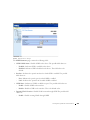
Notes, Notices, and Cautions
NOTE: Notes indicate important information that helps you make better use of your device.
NOTICE: Notices indicate either potential damage to hardware or loss of data and tells you
how to avoid the problem.
CAUTION: Caution indicates a potential for property damage, personal injury, or
death.
Information in this document is subject to change without notice.
© 2003 Dell Inc. All rights reserved.
Reproduction in any manner whatsoever without the written permission of Dell Inc. is strictly forbidden.
Trademarks used in this text: Dell, the DELL logo, PowerConnect, Dell OpenManage, PowerEdge, Inspiron, Dell
Precision, Dimension, OptiPlex, Axim, PowerVault, PowerApp, DellNet, and Latitude are trademarks of Dell Inc.;
Microsoft and Windows are registered trademarks of Microsoft Corporation.
Other trademarks and trade names may be used in this document to refer to either the entities claiming the marks and
names or their products. Dell Inc. disclaims any proprietary interest in trademarks and trade names other than its own.
November 2003
Rev. A01
Contents
1 Overview
System Description
. . . . . . . . . . . . . . . . . . . . . . . . .
. . . . . . . . . . .
12
. . . . . . . . . . . . . . . . . .
13
. . . . . . . . . . . . . . . . . . . . .
14
. . . . . . . . . . . . . . . . . . . . . . .
15
PowerConnect 3324/3348 Stacking Overview
Stack Members and Unit ID .
Configuration Handling
Rearranging Stacks
12
Replacing Stack Members .
. . . . . . . . . . . . . . . . . . .
PowerConnect User Guide Overview
15
. . . . . . . . . . . . . . . .
17
. . . . . . . . .
17
Installing the PowerConnect 3324/3348 Switch
Using the Dell OpenManage Switch Administrator .
. . . . . . .
17
. . . . . . . . . .
18
. . . . . . . . . . . . . . .
20
PowerConnect 3324/3348 Dimensions
. . . . . . . . . . . . .
20
PowerConnect 3324/3348 Rear Panel
. . . . . . . . . . . . . .
20
. . . . . . . . . . . . .
20
PowerConnect 3324/3348 CLI Documentation
2 Hardware Description
PowerConnect 3324/3348 Description
PowerConnect 3324/3348 Components
. . . . . . . . . . . . . . . . . . . . . . . . . .
24
Ethernet Port Description
. . . . . . . . . . . . . . . . . . . .
24
Console Port Description
. . . . . . . . . . . . . . . . . . . .
24
. . . . . . . . . . . . . . . . . . . . . . . . . . .
24
. . . . . . . . . . . . . . . . . . . . . . . . . . .
26
. . . . . . . . . . . . . . . . . . . . . . . . . .
26
. . . . . . . . . . . . . . . . . . . . . . . . .
28
Ports Description
LED Definitions
Port LEDs
System LEDs
Stacking LEDs
Contents
3
3 Installing the PowerConnect 3324/3348 Switch
Installation Precautions
Site Requirements
. . . . . . . . . . . . . . . . . . . . . .
30
. . . . . . . . . . . . . . . . . . . . . . . . .
30
Unpacking and Installation
31
. . . . . . . . . . . . . . . . . . . . . . .
31
. . . . . . . . . . . . . . . . . . . . . . . . . . .
31
Package Contents
Unpacking
. . . . . . . . . . . . . . . . . . . .
. . . . . . . . . . . . . . . . . . . .
32
Installing the Switch without a Rack
. . . . . . . . . . . . . .
32
Stacking PowerConnect 3324/3348
. . . . . . . . . . . . . .
33
. . . . . . . . . . . . . . . . . .
33
Device Rack Installation
Connecting Stacking Cables
Connecting the PowerConnect 3324/3348 to a
Power Supply . . . . . . . . . . . . . . . .
. . . . . . . . .
34
. . . . . . . . . . . . . . .
35
Port Connections .
. . . . . . . . . . . . . . . . . . . . . . .
36
Cable Connections
. . . . . . . . . . . . . . . . . . . . . . .
38
Cable, Port, and Pinout Information
4 Configuring the PowerConnect 3324/3348 Switch
Configuration Overview
. . . . . . . . . . . . . . . . . . . . . .
General Configuration Information
. . . . . . . . . . . . . . . .
43
. . . . . . . . . . . . . . . . . . . . . . .
43
. . . . . . . . . . . . . . . .
44
. . . . . . . . . . . . . . . . . . . . . . . . . . .
45
Auto-Negotiation
Switching Port Default Settings
Baud Rate
Terminal Connection Configuration
. . . . . . . . . . . . . . . .
45
Other Configuration Requirements
. . . . . . . . . . . . . . . .
46
. . . . . . . . . . . . . . . . . . . . . . . .
46
Booting the Device
Device Configuration Introduction
. . . . . . . . . . . . . . . .
48
. . . . . . . . . . . . . . . . . . . . . . .
49
. . . . . . . . . . . . . .
49
. . . . . . . . . . . . . . . . . . . . . . . .
51
Initial Configuration .
Static IP Address and Subnet Mask
Default Gateway
4
42
Contents
. . . . . . . . . . .
51
. . . . . . . . . . . . . . . . . . .
51
. . . . . . . . . . . . . . . . . . . . . .
53
Retrieving an IP address from a DHCP Server
. . . . . . . . .
54
Receiving an IP address from a BOOTP Server
. . . . . . . . .
55
User Name, Password, and Privilege Level
SNMP Community Strings
Advanced Configuration
. . . . . . .
56
. . . . . . . . . . . . . . . . .
57
Sample Configuration Process
. . . . . . . . . . . . . . . . . . .
60
Device Setup Requirements
. . . . . . . . . . . . . . . . . . .
60
. . . . . . . . . . . . . . . . . . . . . . . .
60
. . . . . . . . . . . . . . . . . . . . .
64
. . . . . . . . . . . . . . . . . .
65
. . . . . . . . . . . . .
68
. . . . . . . . . . . . . . . . . . . . . . . . . .
70
. . . . . . . . . . . . . . . . . . .
72
. . . . . . . . . . . . . . . . . . . . . . .
75
. . . . . . . . . . . . . . . . . . . . . .
75
. . . . . . . . . . . . . . . . . . . . .
75
. . . . . . . . . . . . . . . . . . . . . . .
75
. . . . . . . . . . . . . . . . . . . . . .
76
. . . . . . . . . . . . . . . . . . . . . . . .
76
Security Management and Password Configuration
Configuring Security Passwords
Initial Connection
Device Default Settings
Remote Management Access
Start Running the Management Station
Telnet access
Web Access (HTTP server)
Configuring Stacking .
Stacking Introduction
Stacking Requirements
Configuring a Stack
Expanding the Stack
Rebooting the Device
Startup Menu Functions
. . . . . . . . . . . . . . . . . . . . . .
77
. . . . . . . . . . . . . . . . . . .
77
Erasing the FLASH File
. . . . . . . . . . . . . . . . . . . .
78
Erasing FLASH Sectors
. . . . . . . . . . . . . . . . . . . .
79
. . . . . . . . . . . . . . . . . . . . . . .
80
Downloading the Software
Password Recovery
Running Diagnostics .
. . . . . . . . . . . . . . . . . . . . . .
Downloading the Software to Stacking Units
80
. . . . . . . . . . .
80
Downloading the Software Sequentially Using the CLI
. . . . .
81
Downloading the Software Individually Using the CLI
. . . . . .
82
Downloading the Software Via the
PowerConnect 3324/3348 Dell OpenManage Switch
Administrator . . . . . . . . . . . . . . . . . . . .
. . . . . .
84
Contents
5
Defining SNMP Settings
Connecting Devices
. . . . . . . . . . . . . . . . . . . . .
85
. . . . . . . . . . . . . . . . . . . . . . . .
86
5 Getting Started
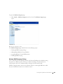
Starting the Switch Administrator
. . . . . . . . . . . . . . . .
88
. . . . . . . . . . . . . . . . . . .
88
. . . . . . . . . . . . . . . . . . . . . . . . . . .
89
. . . . . . . . . . . . . . . . . . . . . . . . . .
90
. . . . . . . . . . . . . . . . . . . . .
90
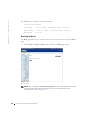
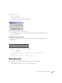
Understanding the Interface
Tree View
Device View
Device Representation
Using the Switch Administrator Buttons
. . . . . . . . . . . . .
92
. . . . . . . . . . . . . . . . . . . . . .
93
. . . . . . . . . . . .
95
. . . . . . . . . . . . . . . . . . . . . . . . . . .
97
. . . . . . . . . . . . . . . . . . . . . . . .
97
. . . . . . . . . . . . . . . . . . . . . . .
97
. . . . . . . . . . . . . . . . . . . .
98
. . . . . . . . . . . . . . . . . .
99
. . . . . . . . . . . . . . . . .
99
. . . . . . . . . . . . . . . . . . . . . . . . . .
100
. . . . . . . . . . . . . . . . . . . . . .
100
. . . . . . . . . . . . . . . . . . . . . . .
101
Information Buttons
About PageDevice Management Buttons
Using the CLI
Command Mode
User EXEC Mode
Privileged EXEC Mode
Global Configuration Mode
Interface Configuration Mode
Starting the CLI
Console Connection
Telnet Connection
6 Configuring System Information
Defining General Device Information
. . . . . . . . . . . . . . .
104
. . . . . . . . . . . . . . . . . . . .
105
. . . . . . . . . . . . . .
109
. . . . . . . . . . . . . . . . . . .
110
. . . . . . . . . . . . . . . . . . . . . .
112
Viewing the Asset Page
Viewing System Health Information
Viewing the Versions Page
Resetting the Device
6
Contents
Managing Logs
. . . . . . . . . . . . . . . . . . . . . . . . . .
Defining Global Log Parameters .
113
. . . . . . . . . . . . . . .
114
. . . . . . . . . . . . . . . . . .
118
. . . . . . . . . . . . . . . . .
121
. . . .
121
. . . . . . . .
123
Defining Device IP Addresses
. . . . . . . . . . . . . . . . . .
126
Defining Default Gateways
Displaying RAM Log Table
Displaying the Log File Table
Displaying the Log File Table Using the CLI Commands
Viewing the Remote Log Server Settings Page .
. . . . . . . . . . . . . . . . . .
127
. . . . . . . . . . . . . . . . . . . .
130
. . . . . . . . . . . . . . . . .
133
. . . . . . . . . . . . . . . . . . . . . . .
136
Defining IP Interfaces .
Defining DHCP IP Interfaces
Configuring ARP
Managing Device Security
. . . . . . . . . . . . . . . . . . . .
Defining Access Profiles .
. . . . . . . . . . . . . . . . . . .
139
141
Defining Authentication Profiles .
. . . . . . . . . . . . . . .
148
Assigning Authentication Profiles
. . . . . . . . . . . . . . .
152
. . . . . . . . . . . . . .
157
. . . . . . . . . . . . . . . . . . .
160
Defining the Local User Databases
Defining Line Passwords
Defining Enable Password .
. . . . . . . . . . . . . . . . . .
161
. . . . . . . . . . .
163
. . . . . . . . . . . . . . . . . . .
168
. . . . . . . . . . . . . . . . . . . . .
169
. . . . . . . . . . . . . . . . . . . . . . . .
171
. . . . . . . . . . . . . . . . . . . . . . . . . .
175
Configuring RADIUS Global Parameters
Defining SNMP Parameters
Defining Communities
Defining Traps
Managing Files
. . . . . . . . . . . . . . . . . .
176
. . . . . . . . . . . . . . . . . . . . . .
177
File Management Overview
Downloading Files .
. . . . . . . . . . . . . . . . . . . . . . . .
180
Resetting the Active Image
. . . . . . . . . . . . . . . . . .
182
Copying and Deleting Files
. . . . . . . . . . . . . . . . . .
183
. . . . . . . . . . . . . . . . . . .
186
. . . . . . . .
187
Uploading Files
Defining Advanced Settings
Configuring General Device Tuning Parameters
Contents
7
7 Configuring Switch Information
Configuring Network Security
. . . . . . . . . . . . . . . . . .
190
. . . . . . . . . . . . . . . . . .
191
. . . . . . . . . . . . . . . . . . .
193
. . . . . . . . . . . . . . . . . . . .
196
. . . . . . . . . . . . . . . . . .
200
Binding ACLs
. . . . . . . . . . . . . . . . . . . . . . . . .
205
Configuring Ports
. . . . . . . . . . . . . . . . . . . . . . . . .
207
. . . . . . . . . . . . . . . . . . .
208
. . . . . . . . . . . . . . . . . . .
216
. . . . . . . . . . . . . . . . . . . .
222
Network Security Overview
Configuring Port Security
Defining IP-Based ACLs
Defining MAC-Based ACLs
Defining Port Parameters
Defining LAG Parameters
Enabling Storm Control
Defining Port Mirroring Sessions .
. . . . . . . . . . . . . . .
225
. . . . . . . . . . . . . . . . . . . .
229
. . . . . . . . . . . . . . . . . . .
230
. . . . . . . . . . . . . . . . . .
233
. . . . . . . . . . . . . . . . . . . . . . . . .
235
. . . . . . . . . . . . . . . . . . . . .
236
Configuring Address Tables
Defining Static Addresses
Viewing Dynamic Addresses
Configuring GARP
Defining GARP Timers
. . . . . . . . . . . . .
239
. . . . . . . . . . . . . . . . .
240
Defining STP Port Settings
. . . . . . . . . . . . . . . . . .
244
Defining STP LAG Settings
. . . . . . . . . . . . . . . . . .
248
Configuring the Spanning Tree Protocol
Defining STP Global Settings
Configuring Rapid Spanning Tree .
Configuring VLANs
. . . . . . . . . . . . . . .
251
. . . . . . . . . . . . . . . . . . . . . . . .
254
. . . . . . . . . . . . . . . . . . .
256
Defining VLAN Ports Settings
. . . . . . . . . . . . . . . . .
261
Defining VLAN LAG Settings
Defining VLAN Members
. . . . . . . . . . . . . . . . .
264
. . . . . . . . . . . . . . . . . . . . . . .
267
. . . . . . . . . . . . . . . . . . . . . . . . .
272
Defining LACP Parameters
. . . . . . . . . . . . . . . . . .
274
Defining LAG Membership
. . . . . . . . . . . . . . . . . . .
279
Configuring GVRP
Aggregating Ports
8
Contents
Multicast Forwarding Support
. . . . . . . . . . . . . . . . . .
Defining IGMP Snooping Settings .
280
. . . . . . . . . . . . . .
281
. . . . . . . . . . .
284
Adding Bridge Multicast Group Members
. . . . . . . . .
287
. . . . . . . . . . . . . . . . . . .
289
. . . . . . . . . . . . . . . . . . . . . . . . . .
294
. . . . . . . . . . . . . . . . .
295
Viewing Counter Summary
. . . . . . . . . . . . . . . . . .
297
Viewing Interface Statistics
. . . . . . . . . . . . . . . . . .
298
Assigning Multicast Forward All Parameters
Enabling IGMP Snooping
8 Viewing Statistics
Viewing Tables
Viewing Utilization Summary
. . . .
300
. . . . . . . . . . . . . . . . . .
301
. . . . . . . . . . . . . . . . . . .
304
. . . . . .
305
. . . . . . . . . . . . . . . . . . .
307
. . . . . . . . . . . . . . . . . . .
307
Viewing History Control Statistics
. . . . . . . . . . . . . .
310
Viewing The RMON History Table
Viewing Interface Statistics Using the CLI Commands
Viewing Etherlike Statistics
Viewing GVRP Statistics
Viewing GVRP Statistics Using the CLI Commands
Viewing RMON Information
Viewing RMON Statistics
. . . . . . . . . . . . . . .
313
Defining Device Events
. . . . . . . . . . . . . . . . . . . .
316
Viewing the Events Log
. . . . . . . . . . . . . . . . . . . .
320
Defining Device Alarms
. . . . . . . . . . . . . . . . . . . .
321
Viewing Charts
. . . . . . . . . . . . . . . . . . . . . . . . . .
326
Viewing Port Statistics
. . . . . . . . . . . . . . . . . . . .
327
Viewing LAG Statistics
. . . . . . . . . . . . . . . . . . . .
331
9 Configuring Quality of Service
Quality of Service (QoS) Overview
. . . . . . . . . . . . . . . .
336
Contents
9
Defining QoS Global Parameters
. . . . . . . . . . . . . . . . .
339
Configuring Global QoS Settings
. . . . . . . . . . . . . . . .
340
Defining QoS Interface Settings
. . . . . . . . . . . . . . . .
342
. . . . . . . . . . . . . . . . . . . .
343
. . . . . . . . . . . . . . . . . . . . . . . .
346
. . . . . . . . . . . . . . . .
346
Defining Queue Settings
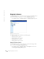
Mapping to Queues
Mapping CoS Values to Queues
Mapping DSCP Values to Queues .
. . . . . . . . . . . . . . .
348
. . . . . . . . . . . . . .
350
Mapping TCP Port Values to Queues
Mapping UDP Port Values to Queues .
. . . . . . . . . . . . .
353
10 Getting Help
Technical Assistance .
Online Services
. . . . . . . . . . . . . . . . . . . . . . .
358
. . . . . . . . . . . . . . . . . . . . . . . .
358
. . . . . . . . . . . . . . . . . . . . . . .
359
. . . . . . . . . . . . . . . .
359
. . . . . . . . . . . . . . . . . . .
360
AutoTech Service
Automated Order-Status Service
Technical Support Service
Dell Enterprise Training and Certification
. . . . . . . . . . . .
360
. . . . . . . . . . . . . . . . . . . .
360
. . . . . . . . . . . . . . . . . . . . . . .
360
Problems With Your Order .
Product Information .
Returning Items for Warranty Repair or Credit .
10
. . . . . . . . .
360
Before You Call
. . . . . . . . . . . . . . . . . . . . . . . . . .
361
Contacting Dell
. . . . . . . . . . . . . . . . . . . . . . . . . .
361
Contents
SECTION 1
Overview
System Description
PowerConnect 3324/3348 Stacking Overview
PowerConnect User Guide Overview
PowerConnect 3324/3348 CLI Documentation
w w w. d e l l . c o m | s u p p o r t . d e l l . c o m
System Description
The Dell™ PowerConnect™ 3324 and 3348 devices are standalone and stackable advanced
Layer 2 switches. PowerConnect 3324 and PowerConnect 3348 also function as stand-alone
Layer 2 switching systems. PowerConnect 3324/3348 devices are managed either using InBand Management (via the network station remotely) or via the console.
PowerConnect 3324
When operating as a stack member, each PowerConnect 3324 unit provides 24 10
BaseT/100BaseTX Fast Ethernet ports, one Gigabit Ethernet Combo port (10/100/1000
BaseT or Mini GBIC connector), and one Giga Ethernet stacking port.
PowerConnect 3348
When operating as a stack member, each PowerConnect 3348 unit provides 48 10
BaseT/100BaseTX Fast Ethernet ports, one Gigabit Ethernet Combo port (10/100/1000
BaseT or Mini GBIC connector), and one Giga Ethernet stacking port.
When operating as a stand-alone unit, the PowerConnect 3324/3348 stacking ports can be
used as Giga Ethernet ports.
PowerConnect 3324/3348 Stacking Overview
PowerConnect 3324/3348 stacking provides multiple device management through a single
point as if all stack members are a single unit. All members are accessed through a single IP
address for SNMP management and a console/telnet session through which the entire stack
is managed.
PowerConnect 3324/3348 supports stacking up to six units per stack or scale up to 192 FE
and six Gigabit Ethernet ports. PowerConnect 3324/3348 can also operate as standalone
units.
12
Over view
During the stacking setup, one device is selected by the network administrator as the stack
master, while all other devices are selected as stack members and assigned a unique Unit ID.
PowerConnect 3324/3348 stacks provide across-the-stack Layer 2 functionality including:
•
Switching
•
Trunking
•
Port Mirroring
•
VLANs
For example, VLANs can be configured from ports belonging to different stack members, or
configure port mirroring from a second stack member to a third stack member. Applications
running in a stacking configuration are centralized. For example, the Spanning Tree
Protocol for the entire stack runs on the master unit. Device software is downloaded
separately for each stack member.
PowerConnect 3324/3348 stacking architecture provides dynamic learning for the stacking
topology, while detecting and reconfiguring the ports with minimal operational impact in
the event of:
•
Unit Failure
•
Inter-unit Link Loss
•
Unit Insertion
•
Removal of a Stacking Unit
Stack Members and Unit ID
The stacking operation mode is determined during the Boot process.
PowerConnect 3324/3348 units are shipped with a default Unit ID of one. The Unit ID is
essential to the stacking configuration. If a stack member reboots without a stacking
module, the device operates as a stand-alone until the device is reset. If a PowerConnect
3324/3348 unit is operating as a stand-alone unit, all stacking LEDs are off. The Unit ID is
not erased and remains valid if the unit is reconnected to a stack.
NOTE: The stacking module must be inserted into port G2 for the stack to operate. If the
stacking module is inserted in port G1, a warning message is displayed on the console.
Over view
13
w w w. d e l l . c o m | s u p p o r t . d e l l . c o m
When the master unit boots or when inserting or removing a stack member, the master unit
initiates a stacking discover process. If two members are discovered with the same Unit ID,
or a master unit is not found, the entire stack cannot function. The stacking LED remains
red.
Configuration Handling
In a PowerConnect 3324/3348 operative stack, the stack master is responsible for the stack
configuration. Each stack member does not have a separate configuration file. Each port in
the stack has a specific Unit ID/port type and port number, which is part of both the
configuration commands and the configuration files. Configuration files are managed only
from the PowerConnect 3324/3348 stack master, including:
•
Saving to the FLASH.
•
Uploading Configuration files to an external TFTP Server.
•
Downloading Configuration files from an external TFTP Server.
NOTE: Stack configuration for all configured ports is saved, even if the stack is reset and/or the
ports are no longer present.
Configuration files are changed only through explicit user configuration. In addition,
Configuration files are not automatically modified when:
•
Units are added.
•
Units are removed.
•
Units are reassigned Unit IDs.
•
Units toggle between stacking mode and stand-alone mode.
Each time the system reboots, the stored configuration is written in the Startup
Configuration file.
If a PowerConnect 3324/3348 stack member is removed from the stack, and then replaced
with the same Unit ID, the stack member is configured with the original device
configuration.
Only ports that are physically present are displayed in the Dell OpenManage™ Switch
Administrator and can be configured through the web management system. Non-present
ports are configured through the CLI or SNMP interfaces.
14
Over view
Rearranging Stacks
The stacking order can be changed by either removing a stack member or by rearranging the
stacking cables. The order in which stack members are arranged is established not by the
physical order of the stack members but by the Unit ID assignment. The stack
configuration is stored in stack master after the stack order is changed, and the stack is
reset.
If the PowerConnect 3324/3348 unit is removed or replaced in a stack, the stack recovers
from the disconnection as follows:
•
If the stack is disconnected for more than two minutes, the entire stack no longer
forwards network traffic. Every stack member reboots and waits until the stack is
reconnected. If the unit is not replaced, the master unit constantly polls the stack.
•
If the stack is reconnected in under two minutes, all units remain stacked and regain
their connection to other units within five seconds. A new stack member is connected
to the master unit but initialized according to the master unit’s configuration. If a
configuration is not stored, the device is configured with the default configuration.
Replacing Stack Members
If a stack member is replaced with a new device, the requested device ID is selected. In
addition, the previous device configuration is applied to the inserted stack member. If the
new inserted device has either more or fewer ports than the previous device, the relevant
port configuration is applied to the new stack member. For example:
•
If a PowerConnect 3324 replaces a PowerConnect 3324, the new 24 10/100 BaseT
ports receive the previous 24 10/100 BaseT port configuration. Ports G1 and G2 receive
the previous device’s G1 and G2 port configuration.
•
If a PowerConnect 3324 replaces PowerConnect 3348, then ports 1-24 10/100 BaseT
receive the previous device’s configuration for ports 1-24. Ports G1 and G2 receive the
previous device’s G1 and G2 port configuration.
Over view
15
w w w. d e l l . c o m | s u p p o r t . d e l l . c o m
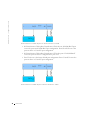
PowerConnect 3324 Replaces PowerConnect 3348
•
If a PowerConnect 3348 replaces PowerConnect 3348, the new 48 10/100 BaseT ports
receive the previous 48 10/100 BaseT port configuration. Ports G1 and G2 receive the
previous device’s G1 and G2 port configuration.
•
If a PowerConnect 3348 replaces PowerConnect 3324, then ports 1-24 10/100 BaseT
receive the previous device’s configuration for ports 1-24.
•
Ports 25-48 receive the factory default port configuration. Ports G1 and G2 receive the
previous device’s G1 and G2 port configuration.
PowerConnect 3348 Replace PowerConnect 3324
16
Over view
PowerConnect User Guide Overview
The PowerConnect User Guide is divided into two parts:
•
About Installing the PowerConnect 3324/3348 Switch
•
Using the Dell OpenManage Switch Administrator
Installing the PowerConnect 3324/3348 Switch
This section contains the following sections about unpacking, installing, and configuring
the PowerConnect 3324/3348:
•
Hardware Description—Contains information about the PowerConnect 3324/3348
hardware, including a description of the ports and LED types.
•
Installing the PowerConnect 3324/3348 Switch—Contains instructions about
installing PowerConnect 3324/3348 in either a rack or on a flat surface. In addition,
this section contains installation precautions, and a description of the connectors and
cables.
•
Configuring the PowerConnect 3324/3348 Switch—Contains instructions about
initial device configuration, including downloading device software, the device boot
screen, and optional configuration functions.
Using the Dell OpenManage Switch Administrator
This section contains the following information about configuring the device using the web
management system and Command Line Interface (CLI) device management system:
•
Getting Started—Contains information about getting started with the web
management system interface, including an explanation of the management and
information icons, the Components List, and the Device and Tree Views.
•
Configuring System Information—Contains information about configuring general
system information including defining system information, configuring a default IP
address, defining device security and SNMP communities, downloading the device
software, and defining advanced settings.
•
Configuring Switch Information—Contains information about configuring port and
VLANs, defining both static and dynamic address tables, configuring GARP and
GVRP, defining Spanning Tree parameters, aggregating ports, and configuring
Multicast forwarding support.
•
Viewing Statistics—Contains information about viewing table and chart statistics for
ports, GVRP, Etherlike, RMON, and interface statistics.
Over view
17
w w w. d e l l . c o m | s u p p o r t . d e l l . c o m
•
Configuring Quality of Service—Contains information about configuring device Class
of Service.
•
Getting Help—Contains information about technical assistance, problems with your
order, returning items for repair or credit, and how to contact Dell.
PowerConnect 3324/3348 CLI Documentation
In addition to the PowerConnect 3324/3348 User Guide, Dell provides the PowerConnect
3324/3348 CLI Reference Guide. The PowerConnect 3324/3348 CLI Reference Guide
provides information about the CLI commands used to configure the PowerConnect
3324/3348.
18
Over view
SECTION 2
Hardware Description
PowerConnect 3324/3348 Description
Ports Description
LED Definitions
w w w. d e l l . c o m | s u p p o r t . d e l l . c o m
PowerConnect 3324/3348 Description
PowerConnect 3324/3348 Dimensions
This device has the following dimensions:
•
Width—19”
•
Height—1U
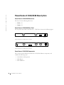
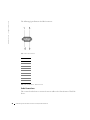
PowerConnect 3324/3348 Rear Panel
The rear panel of the Dell™ PowerConnect™ 3324/3348 is shown in the following figure:
RPS - DC
RPS Connector
Power
Connector
PowerConnect 3324 Rear Panel
RPS - DC
Console Port
RPS Connector
Power Connector
PowerConnect 3348 Rear Panel
PowerConnect 3324/3348 Components
This section describes different PowerConnect 3324/3348 hardware components, and
includes the following topics:
20
•
General Device Components
•
Mode Button
•
Stack ID Button
Hardware Description
General Device Components
The PowerConnect 3324/3348 includes the following hardware components:
•
CPU—Based on Motorola’s MPC 8245.
•
FLASH—Contains 8 MB of FLASH Memory.
•
SDRAM—Contains 32 MB.
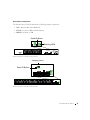
Stack ID Button
1
2
3
4
5
6
Stacking LEDs
3
4
1
2
1
2
3
4
5
6
5
6
7
8
9
10
7
8
11
12
9
10
15
16
13
14
11
12
13
14
17
18
15
16
19
20
17
18
21
22
19
20
23
24
21
22
23
24
G1
G2
1
2
3
4
5
6
PowerConnect 3324 Front Panel
Stacking LEDs
1 2 3
Stack ID Button
4 5 6
G1
3
4
1
2
1
2
3
4
5
6
5
6
7
8
7
8
9
10
9
10
11
12
11
12
15
16
13
14
13
14
15
16
17
18
17
18
19
20
19
20
21
22
21
22
23
24
23
24
27
28
25
26
25
26
27
28
G2
29
30
29
30
31
32
31
32
33
34
33
34
35
36
35
36
39
40
37
38
37
38
39
40
41
42
41
42
43
44
43
44
45
46
45
46
47
48
47
48
G1
1
2
3
4
5
6
G2
PowerConnect 3348 Front Panel
Hardware Description
21
w w w. d e l l . c o m | s u p p o r t . d e l l . c o m
Mode Button
The Mode Button toggles between port activity and port duplex settings.
Stack ID Button
The PowerConnect 3324/3348 front panel contains a Stack ID button that permits network
administrators to manually select the Stack Master and stack members.
NOTE: The Stack Master and stack members must be selected within 15 seconds after booting
the device. If the Stack Master is not selected within 15 seconds, the device must be reset to
select the Unit IDs.
Once the Stack Master is selected, the remaining devices are defined as stack members.
Master units receive the Unit ID of 1. Stack members receive a separate Unit ID (2-6). For
example, if there are 4 units in a stack, the Master unit is 1, the second stack member is 2,
the third stack member is 3, and the fourth stack member is 4.
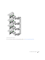
Stacking Modules and Connectors
PowerConnect 3324/3348 Stacking modules are connected to port G2. The Stack module is
a mini GBIC module with two stacking connectors: RX and TX. RX is the lower connection
point, and TX is the upper connection point. The module is connected to other stacking
units using a stacking cable connection. The top unit’s RX is connected to the lower unit’s
TX. This completes the Ring Topology. The Stacking Connections figure illustrates the
Ring Topology.
22
Hardware Description
Master Unit
#1
Tx
Member Unit
#1
Rx
Tx
Member Unit
#2
Rx
Tx
Rx
Member Unit
#3
Tx
Rx
Stacking Connections
For more information about connecting Stacking cables, see "Connecting Stacking Cables".
Hardware Description
23
w w w. d e l l . c o m | s u p p o r t . d e l l . c o m
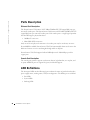
Ports Description
Ethernet Port Description
The PowerConnect 3324 features 24 FE 10BaseT/100BaseTX UTP copper RJ45 ports per
unit and 2 combo ports. The PowerConnect 3348 features 48 FE 10BaseT/100BaseTX UTP
copper RJ45 ports per unit and 2 combo ports. Each combo port is a single logical port that
has the following two physical interfaces:
•
1000Base-T connectors.
•
Mini-GBIC (SFP) connectors.
Only one of the two physical connections of a combo port may be used at any one time.
If auto-MDIX is enabled, PowerConnect 3324/3348 automatically detects and corrects the
difference between crossover and straight-through cables on all ports.
PowerConnect 3324/3348 supports half and full duplex mode 10/100 M bps speed for
copper ports.
Console Port Description
The console port interface supports synchronous data of eight data bits, one stop bit, and
no parity. All RS232 pins are supported (9 pins) for Modem support.
LED Definitions
The front panel LEDs in the following figures indicate the status of port links and modes,
power supply status, stacking status, and system diagnostics. The LED types are as follows:
24
•
Port LEDs
•
System LEDs
•
Stacking LEDs
Hardware Description
System LEDs
3
4
1
2
1
2
Link/Act
Duplex
G1
G2
Mode
Button
3
4
3
4
1
2
1
2
PWR
Diag
RPS
Stack
5
6
3
4
7
8
5
6
9
10
7
8
11
12
9
10
15
16
13
14
11
12
13
14
15
16
17
18
19
20
17
18
21
22
19
20
1
2
3
4
5
6
23
24
21
22
23
24
G1
G2
1
2
3
4
5
6
Front Panel LEDs: 24 Ports
System LEDs
Link/Act
Duplex
G1
G2
3
4
1
2
Mode
Button
1
2
3
4
1
2
3
4
2
3
4
5
6
G1
3
4
1
2
1
5
6
5
6
7
8
7
8
9
10
9
10
11
12
11
12
15
16
13
14
13
14
15
16
17
18
17
18
19
20
19
20
21
22
21
22
23
24
23
24
27
28
25
26
25
26
27
28
G2
29
30
29
30
PWR
Diag
RPS
Stack
31
32
31
32
33
34
33
34
35
36
35
36
39
40
37
38
37
38
39
40
41
42
41
42
43
44
43
44
45
46
45
46
47
48
47
48
49
1
2
3
4
5
6
50
Front Panel LEDs: 48 Ports
Hardware Description
25
w w w. d e l l . c o m | s u p p o r t . d e l l . c o m
Port LEDs
Each port has one corresponding LED located above the port. The LEDs show either link
activity or duplex mode, depending on the port LED display mode. For information about
setting the LED display mode, see "System LEDs".
Color
Activity
Definition
Green
Static
Port link up.
Port operating at 100 Mbps.
Green
Flashing
Port link up with activity.
Port operating at 100 Mbps.
Red
Static
Port link up.
Port operating at 10 Mbps.
Red
Flashing
Port link up with activity.
Port operating at 10 Mbps.
Off
Off
Port link down.
Port Link Activity
Color
Activity
Definition
Green
Static
Port full duplex.
Off
Off
Port link down or half duplex.
Port Duplex Mode
System LEDs
The eight system LEDs indicate the status of various aspects of the device:
26
•
As shown in the front panel figures at the start of this section, the two system LEDs on
the upper left side represent Link Activity and Duplex. These LEDs indicate whether
the port LEDs are displaying link activity or duplex status.
•
The two LEDs on the lower left-side of the figures show the link activity status of Giga
Ports 1 and 2 as follows:
Hardware Description
Color
Activity
Definition
Green
Static
Port link up.
Port operating at 1000 Mbps.
Green
Flashing
Port link up with activity.
Port operating at 1000 Mbps.
Red
Static
Port link up.
Port operating at 10/100 Mbps.
Red
Flashing
Port link up with activity.
Port operating at 10/100 Mbps.
Off
Off
Port link down.
Giga Port Link Activity Status
•
The Mode button located next to the system LEDs is used to toggle between the two
display modes. For an explanation of the port LEDs in each of these modes, see "Port
LEDs".
When a power supply fails, an error message and several traps are generated. The status of
each power supply is indicated by LEDs on the front panel.
•
The four LEDs on the right side show the status of the power supplies, diagnostic
mode, and stack mode as follows:
LED
Color
Activity
Definition
PWR
Green
Static
Power supply operational.
Amber
Static
Power supply failure.
Green
Static
Redundant power supply operational.
Amber
Static
Redundant power supply failure.
Off
Off
Redundant power supply not present.
Diag
Green
Flashing
The system is currently in the
Diagnostic mode.
Stack
Green
Static
Stacking successfully completed.
Off
Off
Standalone.
RPS
P o w e r, D i a g n o s t i c , a n d S t a c k L E D s
Hardware Description
27
w w w. d e l l . c o m | s u p p o r t . d e l l . c o m
Stacking LEDs
The stacking LEDs indicate the unit’s position in the stack. As shown in the front panel
illustrations at the start of this section, the stacking LEDs are numbered 1 through 6. Each
unit in the stack has one stacking LED lit, indicating its position in the stack. When
stacking LED 1 is lit, the unit is the master unit. When one of the stacking LEDs
numbered 2 through 6 is lit, the unit is the corresponding stacking member unit.
28
Hardware Description
SECTION 3
Installing the
PowerConnect
3324/3348 Switch
Installation Precautions
Site Requirements
Unpacking and Installation
Cable, Port, and Pinout Information
w w w. d e l l . c o m | s u p p o r t . d e l l . c o m
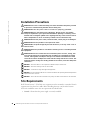
Installation Precautions
CAUTION: The rack or cabinet housing the switch should be adequately secured
to prevent it from becoming unstable and/or falling over.
CAUTION: E n s u r e t h e p o w e r s o u r c e c i r c u i t s a r e p r o p e r l y g r o u n d e d .
CAUTION: Observe and follow service markings. Do not service any product
except as explained in your system documentation. Opening or removing covers
marked with a triangular symbol with a lighting bolt may cause electrical shock.
These components are to be serviced by trained service technicians only.
CAUTION: Ensure the power cable, extension cable, and/or plug is not damaged.
CAUTION: Ensure the product is not exposed to water.
CAUTION: Do not push foreign objects into the device, as it may cause a fire or
electric shock.
CAUTION: Allow the product to cool before removing covers or touching internal
equipment.
CAUTION: Ensure the switch does not overload the power circuits, wiring, and
over-current protection. To determine the possibility of overloading the supply
circuits, add together the ampere ratings of all switches installed on the same
circuit as the switch. Compare this total with the rating limit for the circuit. The
maximum ampere ratings are usually printed on the switch, near their AC power
connectors.
NOTICE: Ensure the device is not exposed to radiators and/or heat sources.
NOTICE: Ensure the cooling vents are not blocked.
NOTICE: Use the device only with approved equipment.
NOTICE: Do not install the switch in an environment where the operating ambient temperature
might exceed 40ºC (122ºF).
NOTICE: Ensure the air flow around the front, sides, and back of the switch is not restricted.
Site Requirements
Dell™ PowerConnect™ 3324/3348 series equipment can be mounted in a standard 19-inch
equipment rack or placed on a table. Before installing the unit, verify that the location
chosen for installation meets the site requirements described below.
•
30
General—Ensure that the power supply is correctly installed.
I n s t a llin g t h e Po we rC on n e c t 3324/3348 Sw itc h
•
Power—The unit is installed within 1.5 m (5 feet) of a grounded, easily accessible
outlet 100-250 VAC, 50-60 Hz. It is preferred that two separate power supplies are
provided, for example, a UPS and a separated phased supply.
•
Clearance—There is adequate frontal clearance for operator access. Allow clearance
for cabling, power connections, and ventilation.
•
Cabling—Cabling is routed to avoid sources of electrical noise such as radio
transmitters, broadcast amplifiers, power lines, and fluorescent lighting fixtures.
•
Ambient Requirements—The ambient unit operating temperature range is 0 to 40ºC
(32 to 122ºF) at a relative humidity of up to 95%, non-condensing. Verify that water or
moisture cannot enter the case of the unit.
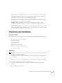
Unpacking and Installation
Package Contents
While unpacking PowerConnect 3324/3348, ensure that the following items are included:
•
The PowerConnect 3324/3348 device.
•
An AC power cable.
•
Null modem cable.
•
Self-adhesive rubber pads.
•
Rack mount kits for rack installation.
•
Documentation CD.
Unpacking
NOTE: Before unpacking the PowerConnect 3324/3348 switch, inspect the package and report
any evidence of damage immediately.
1
Ground yourself by putting on an ESD wrist strap and attaching the ESD clip to a
metal surface.
2
Place the container on a clean flat surface and cut all straps securing the container.
3
Open the container or remove the container top.
4
Carefully remove the unit from the container and place it on a secure and clean
surface.
5
Remove all packing material.
I n s t a l l i n g t h e Po w e r C o n n e c t 3 3 2 4 / 3 3 4 8 S w i t c h
31
w w w. d e l l . c o m | s u p p o r t . d e l l . c o m
6
Inspect the product for damage. Report any damage immediately. For information
about contacting Dell, see "Getting Help".
Device Rack Installation
CAUTION: Disconnect all cables from the unit before mounting the
PowerConnect 3324/3348 switch in a rack or cabinet.
Installing PowerConnect 3324/3348:
1
Ground yourself by putting on an ESD wrist strap and attaching the ESD clip to a
metal surface.
2
Place the PowerConnect 3324/3348 switch on a flat and stable surface.
3
Place the supplied rack-mounting bracket on one side of the PowerConnect
3324/3348. Ensure that the mounting holes on the PowerConnect 3324/3348 line up
with the mounting holes on the rack-mounting bracket.
4
Insert the supplied screws into the rack-mounting holes and tighten with a Phillips
screwdriver.
5
Repeat the process for the rack-mounting bracket on the other side of
PowerConnect 3324/3348.
6
Insert the unit into the 19-inch rack and secure the unit to the rack with the rack
screws (not provided by the PowerConnect 3324/3348 supplier). When securing,
fasten the lower pair of screws before the upper pair of screws to ensure that the weight
of the unit is evenly distributed during installation. Ensure that the ventilation holes
are not obstructed.
Installing the Switch without a Rack
The PowerConnect 3324/3348 must be installed on a flat surface if it is not installed on a
rack. The surface must be able to support the weight of the device and the device cables.
32
1
Set PowerConnect 3324/3348 on a flat surface, leaving 2 inches on each side and
5 inches at the back.
2
Ensure that the device has proper ventilation.
3
Attach the rubber feet to the bottom of the device to prevent the device from slipping.
I n s t a llin g t h e Po we rC on n e c t 3324/3348 Sw itc h
Stacking PowerConnect 3324/3348
PowerConnect 3324/3348 supports stacking up to six PowerConnect 3324/3348 devices or
up to 192 Fast Ethernet ports and six Giga ports. Each PowerConnect 3324/3348 stack
contains a single Master unit, while the remaining units are considered stacking members.
All management is done through the Master unit. Both 24-port and 48-port devices can be
included in the stack.
To enable stacking, units must be stacked with a Stack Module connected to port G2 in the
SFP slot.
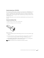
Connecting Stacking Cables
1
Place each device in the rack or on a flat surface.
2
Insert a stacking connector for each G2 port.
USB Connector
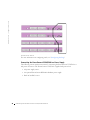
3
Connect the Master unit lower RX stacking connector to the selected member upper
TX port.
4
Connect the stack in a stacking ring topology, where stacking cables are connected
from the lower RX stacking connector into the upper TX Stacking connector.
5
Ensure that the upper and lower stack members are connected via a stacking cable.
The following figure depicts a correctly connected stack:
NOTE: If the Stacking ring is not completed, the stack does not function.
I n s t a l l i n g t h e Po w e r C o n n e c t 3 3 2 4 / 3 3 4 8 S w i t c h
33
w w w. d e l l . c o m | s u p p o r t . d e l l . c o m
Connected Stack
For more information on configuring stacks, see "Configuring Stacking".
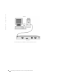
Connecting the PowerConnect 3324/3348 to a Power Supply
The following section contains instruction for connecting the PowerConnect 3324/3348 to a
AC power connection. The PowerConnect 3324/3348 is supplied with power from:
34
•
AC power supply source.
•
An optional PowerConnect RPS-600 redundant power supply.
•
Both AC and DC sources.
I n s t a llin g t h e Po we rC on n e c t 3324/3348 Sw itc h
Connecting PowerConnect 3324/3348 to a Power Supply
•
Plug in the PowerConnect 3324/3348 to one of the previously listed power sources.
AC Power Connection
AC power should be supplied to the unit through a 1.5m (5 foot) standard power cable with
safety-ground connected.
To connect power to PowerConnect 3324/3348:
1
Connect the power cable to the AC main socket located on the rear panel. If there is a
redundant power module, connect this redundant power module cable to a separate
power supply.
2
Connect the power cable to a grounded AC outlet.
3
Confirm that the device is connected and operating correctly by examining the LEDs
on the front panel. For more information about LEDs, see "LED Definitions".
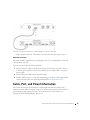
Cable, Port, and Pinout Information
This section describes the PowerConnect 3324/3348 physical interfaces and provides
information about cable connections. Stations are connected to PowerConnect 3324/3348
ports through the physical interface ports on the front panel. For each station, the
appropriate mode (Half/Full Duplex, Auto) is set.
I n s t a l l i n g t h e Po w e r C o n n e c t 3 3 2 4 / 3 3 4 8 S w i t c h
35
w w w. d e l l . c o m | s u p p o r t . d e l l . c o m
Port Connections
The ports are all standard RJ45 Ethernet ports. Switching ports can connect to stations
wired in standard RJ45 Ethernet station mode using straight cables. Transmission devices
use crossed cables to connect to each other.
The following figure illustrates the RJ45 pin number allocations for the 10/100M ports.
RJ45 Pin Number Allocation
Pin
Use
1
RX +
2
RX -
3
TX +
4
36
5
--
6
TX -
7
-
8
-
I n s t a llin g t h e Po we rC on n e c t 3324/3348 Sw itc h
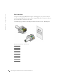
The following figure illustrates the Gigaport Connector:
GigaPort Connector
A serial cable connects PowerConnect 3324/3348 to a terminal for the initial setup and
configuration. (A PC running terminal emulation software can also be used.) The serial
cable is a female-to-female DB-9 crossover cable.
I n s t a l l i n g t h e Po w e r C o n n e c t 3 3 2 4 / 3 3 4 8 S w i t c h
37
w w w. d e l l . c o m | s u p p o r t . d e l l . c o m
The following figure illustrates the DB-9 connector.
DB-9 Serial Cable
Pin
Use
1
Unused
2
TXD
3
RXD
4
Unused
5
GND
6
Unused
7
CTS
8
RTS
9
Unused
DB-9 Pin Number Allocation
Cable Connections
This section describes how to connect the various cables to the PowerConnect 3324/3348
device.
38
I n s t a llin g t h e Po we rC on n e c t 3324/3348 Sw itc h
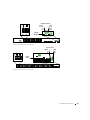
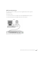
ASCII Terminal (Serial) Connection
The serial port connector is a DB-9 type connector. A supplied interface cable is required to
connect the device.
To connect the device:
1
Connect the interface crossed cable to the terminal ASCII DTE RS-232 connection.
2
Connect the interface crossed cable to the device serial connection.
P o w e r C o n n e c t 3 3 2 4 Te r m i n a l C o n n e c t i o n
I n s t a l l i n g t h e Po w e r C o n n e c t 3 3 2 4 / 3 3 4 8 S w i t c h
39
w w w. d e l l . c o m | s u p p o r t . d e l l . c o m
P o w e r C o n n e c t 3 3 4 8 Te r m i n a l C o n n e c t i o n
40
I n s t a llin g t h e Po we rC on n e c t 3324/3348 Sw itc h
SECTION 4
Configuring the
PowerConnect
3324/3348 Switch
Configuration Overview
General Configuration Information
Terminal Connection Configuration
Other Configuration Requirements
Booting the Device
Device Configuration Introduction
Initial Configuration
Advanced Configuration
Sample Configuration Process
Configuring Stacking
Rebooting the Device
Startup Menu Functions
Downloading the Software to Stacking Units
Defining SNMP Settings
Connecting Devices
w w w. d e l l . c o m | s u p p o r t . d e l l . c o m
Configuration Overview
This section describes the initial device configuration and includes:
•
Initial Device Bootup
•
Preliminary Configuration Requirements
•
Configuring Stacking
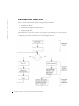
After all the device external connections are in place, a terminal must be connected to the
device to monitor the boot and other procedures. The order of installation and
configuration procedures are illustrated in the following flowchart:
42
C o n f i g u r i n g t h e Po w e r C o n n e c t 3 3 2 4 / 3 3 4 8 S w i t c h
Instructions for setting up the device and hardware are provided in the preceding sections.
For a first-time installation, the standard device installation is performed. There are other
special functions which can be performed, but this suspends the installation process and
results in a system reboot. This option is described later in this section.
General Configuration Information
Dell™ PowerConnect™ 3324/3348 is provided with pre-defined implemented features and
setup configuration.
Auto-Negotiation
Auto-negotiation allows a device to advertise modes of operation and share information
with another device that shares a point-to-point link segment. This automatically
configures both devices to take maximum advantage of their abilities.
Auto-negotiation is performed completely within the physical layers during link initiation,
without any additional overhead to either the MAC or higher protocol layers. Autonegotiation allows the ports to do the following:
•
Advertise their abilities.
•
Acknowledge receipt and understanding of the common modes of operation that both
devices share.
•
Reject the use of operational modes that are not shared by both devices.
•
Configure each port for the highest-level operational mode that both ports can
support.
If connecting a port of the switch to the network interface controller (NIC) of a workstation
or server that does not support auto-negotiation or is not set to auto-negotiation, both the
switching port and the NIC must be manually set with the Web browser interface or CLI
commands to the same speed and duplex mode.
NOTICE: If the station on the other side of the link attempts to auto-negotiate with a port that
is manually configured to full duplex, the auto-negotiation results in the station attempting to
operate in half duplex. The resulting mismatch may lead to significant frame loss. This is
inherent in the auto-negotiation standard.
C o n f i g u r i n g t h e Po w e r C o n n e c t 3 3 2 4 / 3 3 4 8 S w i t c h
43
w w w. d e l l . c o m | s u p p o r t . d e l l . c o m
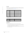
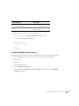
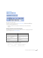
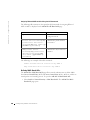
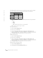
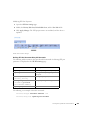
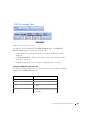
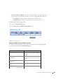
Switching Port Default Settings
The following table describes the Port default settings.
Port Default Settings
Function
Default Setting
Port speed and mode
10/100M copper ports: auto-negotiation
1000M auto-negotiation
Port forwarding state
Enabled
Port tagging
No tagging
Head of line blocking prevention
On (Enabled)
Flow Control
Off
Back Pressure
Off
The following is an example for changing the port speed on port 1/e5 using CLI
commands:
console> enable
console# configure
Console (config)# interface ethernet 1/e5
Console (config-if)# speed 100
The following is an example for enabling flow control on port 1/e5 using CLI commands:
console> enable
console# configure
Console (config)# interface ethernet 1/e5
Console (config-if)# flowcontrol on
The following is an example for enabling back pressure on port 1/e5 using CLI commands:
console> enable
console# configure
Console (config)# interface ethernet 1/e5
Console (config-if)# back-pressure
44
C o n f i g u r i n g t h e Po w e r C o n n e c t 3 3 2 4 / 3 3 4 8 S w i t c h
Baud Rate
The baud rates can be manually changed to any of the following values:
•
2400
•
4800
•
9600
•
19,200
•
38,400
•
57,600
•
115,200
NOTE: The default baud rate is 9600.
NOTE: Closing the device does not return the default baud rate. It must be specifically
configured.
NOTE: In order to enter configuration mode, you must specify administrative level 15
privileges.
The following is an example configuration for changing the default baud rate using CLI
commands:
console> enable
console# configure
console(config)# line console
console(config-line)# speed 9600
console(config-if)# exit
console(config)# exit
Terminal Connection Configuration
The PowerConnect 3324/3348 requires the following Terminal Connection parameters for
configuration:
•
no parity
•
one stop bit
•
8 data bits
C o n f i g u r i n g t h e Po w e r C o n n e c t 3 3 2 4 / 3 3 4 8 S w i t c h
45
w w w. d e l l . c o m | s u p p o r t . d e l l . c o m
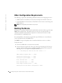
Other Configuration Requirements
The following is required for downloading embedded software and configuring the device:
•
ASCII terminal (or emulation) connected to the Serial port in the back of the unit.
•
Assigned IP address for PowerConnect 3324/3348 for device remote control using with
Telnet, SSH, etc.
NOTE: The configuration process defines only one port.
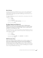
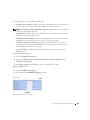
Booting the Device
When power is turned on with the local terminal already connected, a device goes through
POST (Power On Self Test). This built-in power-on test runs every time the device is
initialized. The POST checks hardware components to determine if the device is fully
operational before completing boot up.
If a critical problem is detected, the program flow stops. If POST passes successfully, the
code is decompressed into the RAM memory.
The POST messages are displayed on the terminal and indicate test success or failure.
To boot the device:
1
Ensure the ASCII cable is connected to the terminal.
2
Connect the power supply to the device; the device begins booting up. The boot-up
test first counts the device memory availability and then continues to boot-up. The
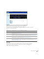
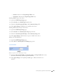
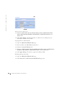
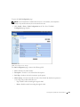
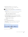
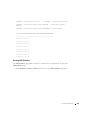
following screen is an example of the displayed POST test:
------ Performing the Power-On Self Test (POST) ------
UART Channel Loopback Test......PASS
Testing the System Cache.......PASS
Testing the System SDRAM.......PASS
Boot1 Checksum Test........PASS
Boot2 Checksum Test........PASS
Flash Image Validation Test......PASS
Testing CPU PCI Bus Device Configuration...PASS
46
C o n f i g u r i n g t h e Po w e r C o n n e c t 3 3 2 4 / 3 3 4 8 S w i t c h
BOOT Software Version 1.30.11 Built 27-JAN-2003 10:06:03
Processor: MPC8245 Rev 0.12, 250 MHz (Bus: 100MHz), 32 MByte SDRAM.
I-Cache 16 KB, linesize 32.D-Cache 16 KB, linesize 32.
Cache Enabled.
Autoboot in 2 seconds - press RETURN or Esc. to abort and enter
prom.
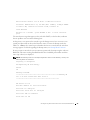
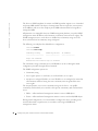
The auto-boot message that appears at the end of the POST (see the last lines) indicates
that no problems were encountered during boot.
At this point, a user input can be entered to get the Startup menu if it is necessary to run
special procedures that can be invoked from this menu. To enter the Startup menu, the
<Esc> or <Enter> keys must be pressed within the first two seconds after the auto-boot
message appears. For details regarding the Startup menu, see Startup Menu Functions.
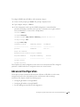
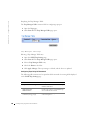
If no user input is entered, the system continues operation by decompressing the code into
RAM. The code starts running from RAM and the list of available port numbers and their
states (up or down) are displayed.
NOTE: The following screen is an example configuration. Items such as addresses, versions, and
dates may differ for each device.
Preparing to decompress.
Decompressing SW from RSCOD_2
85e000
OK
Running from RAM.
******************************************************Running SW
Ver. 3.30 Date 03-Feb-2003 Time 10:10:37
******************************************************
HW version is X.X
Base Mac address is: 00:01:02:03:04:05
Dram size is: 32M bytes
Dram first block size is: 20M bytes
Dram first PTR is: 0xB70000
Flash size is: 8M
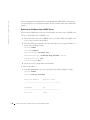
C o n f i g u r i n g t h e Po w e r C o n n e c t 3 3 2 4 / 3 3 4 8 S w i t c h
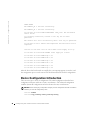
47
w w w. d e l l . c o m | s u p p o r t . d e l l . c o m
STAND ALONE
The BCM5625_A1 0 initiate successfully
The BCM5625_A1 1 initiate successfully
02-Jan-2000 01:01:11%SSHD-W-NOHOSTKEY: SSHG_init: The SSH daemon
cannot listen
for incoming connections, because a host key has not been
generated.
The service will start automatically when a host key is generated.
01-Jan-2000 01:01:11 %INIT-I-InitCompleted: Initialization task is
completed
console> 01-Jan-2000 01:01:12 %PS-I-PSUP: Power Supply #1 is up
01-Jan-2000 01:01:12%PS-W-PSDOWN: Power Supply #2 is down
01-Jan-2000 01:01:12%LINK-W-Up: 1/e1
01-Jan-2000 01:01:12%LINK-W-UP: 1/e2
01-Jan-2000 01:01:12%LINK-W-Up: 1/e3
01-Jan-2000 01:01:12%LINK-W-UP: 1/e4
01-Jan-2000 01:01:12%LINK-W-Up: 1/e5
01-Jan-2000 01:01:13%LINK-W-Up: 1/e9
After the device has been booted successfully, the system prompt appears (console>) and
the configuration process can be started. The local terminal can be used for configuration.
Device Configuration Introduction
There are two types or levels of configuration. The initial configuration describes basic
configuration functions with basic security considerations. The advanced configuration
includes dynamic IP configuration and more advanced security considerations.
NOTICE: After making any configuration changes, the new configuration must be saved before
rebooting. To save the configuration, enter:
console> enable
console# copy running-config startup-config
48
C o n f i g u r i n g t h e Po w e r C o n n e c t 3 3 2 4 / 3 3 4 8 S w i t c h
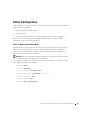
Initial Configuration
Initial configuration starts after the device has booted successfully. The initial configuration
scope for the device includes:
•
Static IP address and Subnet Mask
•
Default gateway
•
User name and privilege level must be configured to allow remote management.
If the device is to be managed from an SNMP-based management station, SNMP
community strings must also be configured.
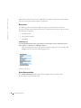
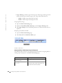
Static IP Address and Subnet Mask
In PowerConnect 3324/3348 devices, IP interfaces can be configured on each port and no
limitation on the number of IP interfaces is imposed. After entering the configuration
command, it is recommended to check if a port was configured with the IP address by
entering the "show ip interface" command.
NOTICE: Only one VLAN can be assigned an IP address. If you assign an address to any other
VLAN, the new address overrides the original IP address.
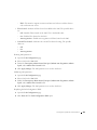
To configure an interface on a VLAN, enter the commands at the system prompt as shown
in the following configuration example:
console> enable
console# configure
console(config)# interface vlan 1
console(config-if)# ip address 100.1.1.1 /8
console(config-if)# exit
console(config)# exit
console# show ip interface
C o n f i g u r i n g t h e Po w e r C o n n e c t 3 3 2 4 / 3 3 4 8 S w i t c h
49
w w w. d e l l . c o m | s u p p o r t . d e l l . c o m
Gateway IP Address
Activity status
----------------------- -----------------------
IP Address
I/F
----------------------- ---------------------100.1.1.1/8
vlan 1
console#
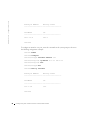
To configure an interface on a port, enter the commands at the system prompt as shown in
the following configuration example:
console> enable
console# configure
console(config)# interface ethernet 1/e1
console(config-if)# ip address 10.1.1.1 255.0.0.0
console(config-if)# exit
console(config)# exit
console# show ip interface
Gateway IP Address
Activity status
----------------------- -----------------------
IP Address
I/F
----------------------- ---------------------10.1.1.1/8
1/e1
console#
50
C o n f i g u r i n g t h e Po w e r C o n n e c t 3 3 2 4 / 3 3 4 8 S w i t c h
Default Gateway
To manage a PowerConnect 3324/3348 device from a remote network, a default gateway,
which is the gateway that a device uses if a specific gateway is not specified, must be
configured. The configured gateway IP address must belong to the same subnet as one of
the device IP interfaces.
To configure a default gateway, enter the command at the system prompt as shown in this
configuration example:
console> enable
console# configure
console(config)# ip default-gateway 100.1.1.100
console(config)# exit
User Name, Password, and Privilege Level
IMPORTANT: To manage a device from a remote terminal or Web Management
Interface, a user name, a password, and the highest privilege level (15) must be entered.
(The highest level provides access to the CLI configure context.) For details about the
privilege level, see the CLI Reference Guide.
The configured user name is entered as a login name for remote management sessions. To
configure user name and privilege level, enter the command at the system prompt as shown
in the configuration example:
console> enable
console# configure
console(config)# username admin password admin level 15
console(config)# exit
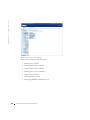
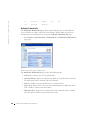
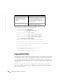
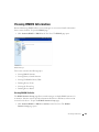
SNMP Community Strings
Simple Network Management Protocol (SNMP) provides a method for managing network
devices. Devices supporting SNMP run a local software (agent). The SNMP agents
maintain a list of variables, used to manage the device. The variables are defined in the
Management Information Base (MIB). The MIB presents the variables controlled by the
agent. The SNMP agent defines the MIB specification format, as well as the format used to
access the information over the network. Access rights to the SNMP agents are controlled
by access strings and SNMP community strings.
C o n f i g u r i n g t h e Po w e r C o n n e c t 3 3 2 4 / 3 3 4 8 S w i t c h
51
w w w. d e l l . c o m | s u p p o r t . d e l l . c o m
The device is SNMP-compliant. It contains an SNMP agent that supports a set of standard
and private MIB variables. Developers of management stations require the exact structure
of the MIB tree and receive the complete private MIBs information before being able to
manage the MIBs.
All parameters are manageable from any SNMP management platform, except the SNMP
management station IP address and community (community name and access rights). The
SNMP management access to the device is disabled if no community strings exist. The
device is delivered with no community strings configured.
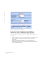
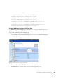
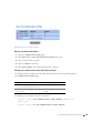
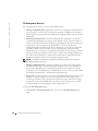
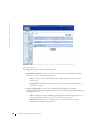
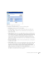
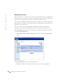
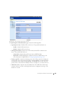
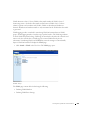
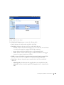
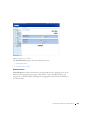
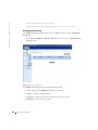
The following screen displays the default device configuration:
console# enable
console# show snmp
Community-String
Community-Access
IP address
--------------------
----------------
---------------
Traps are enabled.
Authentication-failure trap is enabled.
The community-string, community-access and IP address can be set during the initial
configuration procedure through the local terminal.
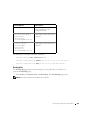
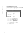
The SNMP configuration options are:
•
Community string
•
Access rights options: ro (read only), rw (read-and-write) or su (super).
•
An option to configure IP address or not: if IP address is not configured, it means that
all community members having the same community name are granted the same
access rights.
The accepted practice is to use two community strings for the device - one (public
community) with read only access and the other (private community) with read-and-write
access:
•
Public — Allow authorized management stations to retrieve MIB objects.
•
Private —Allow authorized management stations to retrieve and modify MIB objects.
During initial configuration, it is recommended to configure the device according to the
network administrator requirements, in accordance with using an SNMP-based
management station.
52
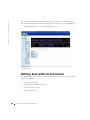
C o n f i g u r i n g t h e Po w e r C o n n e c t 3 3 2 4 / 3 3 4 8 S w i t c h
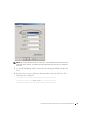
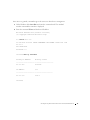
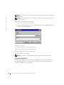
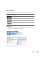
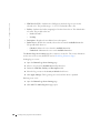
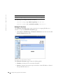
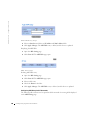
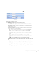
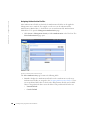
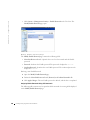
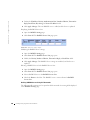
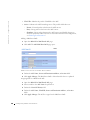
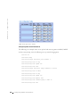
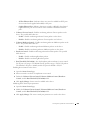
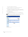
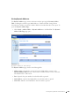
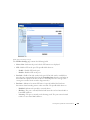
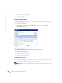
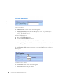
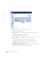
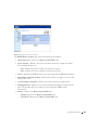
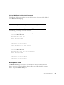
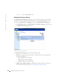
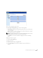
To configure SNMP station IP address and community string(s):
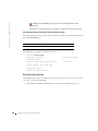
1
At the console prompt, type Enable. The prompt is displayed as #.
2
Type configure and press <Enter>.
3
In the configuration mode, type the SNMP configuration command with the
parameters including community name (private), community access right (read and
write) and IP address, as shown in the example below:
console> enable
config# configure
config(config)# snmp-server community private rw 11.1.1.2
config(config)# exit
config# show snmp
Community-String
Community-Access
IP address
--------------------
----------------
---------------
private
readWrite
11.1.1.2
Traps are enabled.
Authentication-failure trap is enabled.
Trap-Rec-Address
Trap-Rec-Community
Version
----------------
--------------------
-------
System Contact:
System Location:
This completes the initial configuration of the device from a local terminal. The configured
parameters enable further device configuration from any remote location.
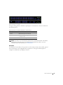
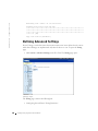
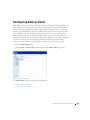
Advanced Configuration
This chapter contains information about dynamic allocation of IP addresses and security
management based on the AAA (authentication, authorization and accounting)
mechanism. The chapter includes the following topics:
•
Configuring IP Addresses through DHCP.
•
Configuring IP Addresses through BOOTP.
•
Security Management and Password Configuration.
C o n f i g u r i n g t h e Po w e r C o n n e c t 3 3 2 4 / 3 3 4 8 S w i t c h
53
w w w. d e l l . c o m | s u p p o r t . d e l l . c o m
When configuring/receiving IP addresses through DHCP and BOOTP, the configuration
received from these servers includes IP address, and may include subnet mask and default
gateway.
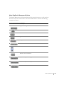
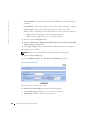
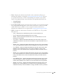
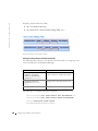
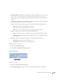
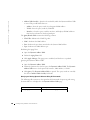
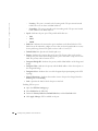
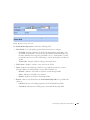
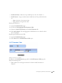
Retrieving an IP address from a DHCP Server
When using the DHCP protocol to retrieve an IP address, the device acts as a DHCP client.
To retrieve an IP address from a DHCP server:
1
Select and connect any port to a DHCP server or to a subnet which has a DHCP server
on it, in order to retrieve the IP address.
2
Enter the following commands to use the selected port for receiving the IP address, as
shown in the following example.
console> enable
console# configure
console(config)# interface vlan 1
console(config-if)# ip address dhcp hostname <string>
console(config-if)# exit
console(config)# exit
3
The device receives the IP address automatically.
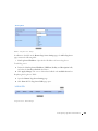
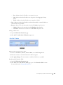
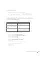
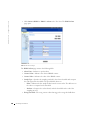
To verify the IP address:
1
Type show ip interface at the system prompt. See the following display example.
console> enable
console# show ip interface
Gateway IP Address
Activity status
----------------------- -----------------------
IP Address
I/F
----------------------- ---------------------10.1.1.1/8
54
vlan1
C o n f i g u r i n g t h e Po w e r C o n n e c t 3 3 2 4 / 3 3 4 8 S w i t c h
console#
NOTE: The device configuration does not need to be deleted to retrieve an IP address for the
DHCP server.
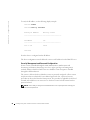
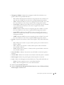
Receiving an IP address from a BOOTP Server
The standard BOOTP protocol is supported enabling the device to automatically download
their IP host configuration from any standard BOOTP server in the internet. In this case,
the device acts as a BOOTP client.
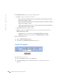
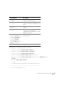
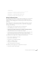
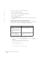
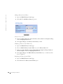
To retrieve an IP address from a BOOTP server:
1
Select and connect any port to a BOOTP server or subnet containing such a server, to
retrieve the IP address.
2
At the system prompt, type in the delete startup configuration command to delete the
Startup configuration from flash. The device reboots with no configuration and in 60
seconds starts sending BOOTP requests.
3
The device receives the IP address automatically.
NOTE: Once the "delete startup configuration" begins, any input at the ASCII terminal or
keyboard automatically aborts the configuration process before completion and the device does
not recieve an IP address from BOOTP.
The following example illustrates the process:
console> enable
console# delete startup-config
C o n f i g u r i n g t h e Po w e r C o n n e c t 3 3 2 4 / 3 3 4 8 S w i t c h
55
w w w. d e l l . c o m | s u p p o r t . d e l l . c o m
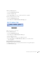
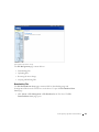
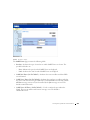
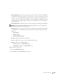
To verify the IP address, see the following display example.
console> enable
console# show ip interface
Gateway IP Address
Activity status
----------------------- -----------------------
IP Address
I/F
----------------------- ---------------------10.1.1.1/8
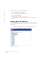
vlan1
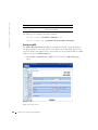
console#
Now the device is configured with an IP address.
The device configuration must be deleted to retrieve an IP address from the BOOTP server.
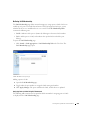
Security Management and Password Configuration
System security is handled through the AAA (Authentication, Authorization and
Accounting) mechanism that manages user access rights, privileges and management
methods. AAA uses both local and remote user databases. Data encryption is handled
through the SSH mechanism.
The system is delivered with no default user name or password configured—all user names
and passwords are user-defined. If a user-defined password is lost, a password recovery
procedure can be invoked from the Startup menu. The procedure is applicable for the local
terminal only and allows a one-time access to the device from the local terminal with no
password entered.
NOTE: Ensure that you always include administrative level 15 privileges when entering your
user name and password.
56
C o n f i g u r i n g t h e Po w e r C o n n e c t 3 3 2 4 / 3 3 4 8 S w i t c h
Configuring Security Passwords
The security passwords can be configured for the following services:
•
Console
•
Telnet
•
SSH
•
HTTP
•
HTTPS
NOTE: Passwords are user-defined.
NOTE: When creating a user name, the default priority is "1", which allows access but not
configuration rights. A priority of "15" must be specifically set to enable access and
configuration rights to the device.
For more information about password limitation, see "Configuring Network Security".
Configuring an Initial Console Password
To configure an initial console password, enter the following commands:
console> enable
console# configure
console(config)# aaa authentication login default line
console(config)# aaa authentication enable default line
console(config)# line console
console(config-line)# login authentication default
console(config-line)# enable authentication default
console(config-line)# password console
console(config-line)# exit
console(config)# exit
•
When initially logging on to a device through a console session, enter console at the
password prompt.
•
When changing a device’s mode to enable, enter console at the password prompt.
C o n f i g u r i n g t h e Po w e r C o n n e c t 3 3 2 4 / 3 3 4 8 S w i t c h
57
w w w. d e l l . c o m | s u p p o r t . d e l l . c o m
Configuring an Initial Telnet Password
To configure an initial Telnet password, enter the following commands:
console> enable
console# configure
console(config)# aaa authentication login default line
console(config)# aaa authentication enable default line
console(config)# line telnet
console(config-line)# login authentication default
console(config-line)# enable authentication default
console(config-line)# password admin
console(config-line)# exit
console(config)# exit
•
When initially logging onto a device through a Telnet session, enter admin.
•
When changing a device mode to enable, enter admin.
Configuring an Initial SSH Password
To configure an initial SSH password, enter the following commands:
console> enable
console# configure
console(config)# aaa authentication login default line
console(config)# aaa authentication enable default line
console(config)# line ssh
console(config-line)# login authentication default
console(config-line)# enable authentication default
console(config-line)# password admin
console(config-line)# exit
console(config)# exit
58
•
When initially logging onto a device through a SSH session, enter admin as the
password.
•
When changing a device’s mode to enable, enter admin as the password.
C o n f i g u r i n g t h e Po w e r C o n n e c t 3 3 2 4 / 3 3 4 8 S w i t c h
Configuring an Initial HTTP Password
To configure an initial HTTP password, enter the following commands:
console> enable
console# configure
console(config)# ip http authentication local
console(config)# username admin password admin level 15
console(config)# exit
Configuring an Initial HTTPS Password
To configure an initial HTTPS password, enter the following commands:
console> enable
console# configure
console(config)# ip https authentication local
console(config)# username admin password admin level 15
console(config)# exit
Enter the following commands once when configuring a console, a telnet, or an SSH session
in order to use an HTTPS session.
NOTE: In the Web browser, enable SSL 2.0 or greater for the content of the page to appear.
console> enable
console# configure
console(config)# crypto certificate generate key-generate
console(config)# ip https server
console(config)# exit
When initially enabling an HTTP or HTTPs session, enter admin for user name and user1
for password.
NOTE: HTTP and HTTPS services require level 15 access and connect directly to the
configuration level access.
C o n f i g u r i n g t h e Po w e r C o n n e c t 3 3 2 4 / 3 3 4 8 S w i t c h
59
w w w. d e l l . c o m | s u p p o r t . d e l l . c o m
Sample Configuration Process
The purpose of this chapter is to present the basic steps required in order to establish a
remote network management connection with the PowerConnect 3324/3348 device. This
chapter does not explain the various configurations available on the device or the relevant
commands.
This chapter describes accessing a device for the first time—still with the factory
configuration and definitions. If a previously entered configuration causes problems, the
startup-configuration file (configuration of device when powered up) should be erased and
device rebooted, see "Device Default Settings".
Device Setup Requirements
The following components are required for the purpose of this example:
•
PowerConnect 3324/3348 device
•
PC workstation with the following installed:
–
A NIC (network adapter) card installed
–
An ASCII terminal application (for example Microsoft® Windows® MS Hyper
Terminal or Procomm Plus Terminal)
–
A browser application
•
One Null Modem F2F cable.
•
Straight or cross UTP (cat 5) cable(s)
Initial Connection
The initial connection is as follows:
60
1
Connect the PowerConnect 3324/3348 device to the RS232 interface of a computer
operating as an ASCII terminal.
2
Set the ASCII terminal with the following settings and select the appropriate COM
port (In this example using Windows Hyper Terminal application):
C o n f i g u r i n g t h e Po w e r C o n n e c t 3 3 2 4 / 3 3 4 8 S w i t c h
NOTE: 9600 is the default baud rate for new device. If using 9600 baud rate does not result in
viewing the device terminal, try another baud rate setting (the device may be set at a different
baud rate).
3
Use an F2F Null Modem cable to connect the PC running the ASCII terminal to the
device.
4
Insert the device’s power cord into an electrical outlet to power up the device. The
following screen is displayed:
**************************************************
*****************
SYSTEM RESET
*****************
**************************************************
C o n f i g u r i n g t h e Po w e r C o n n e c t 3 3 2 4 / 3 3 4 8 S w i t c h
61
w w w. d e l l . c o m | s u p p o r t . d e l l . c o m
Booting...
------ Performing the Power-On Self Test (POST( -----UART Channel Loopback Test........................PASS
Testing the System Cache..........................PASS
Testing the System SDRAM..........................PASS
Boot1 Checksum Test...............................PASS
Boot2 Checksum Test...............................PASS
Flash Image Validation Test.......................PASS
Testing CPU PCI Bus Device Configuration..........PASS
BOOT Software Version 1.0.0.13 Built
11-May-2003
14:58:20
Processor: MPC8245 Rev 0.14, 250 MHz (Bus: 100MHz), 32 MByte SDRAM.
I-Cache 16 KB, linesize 32.D-Cache 16 KB, linesize 32.
Cache Enabled.
Autoboot in 2 seconds - press RETURN or Esc. to abort and enter
prom.
Preparing to decompress...
After the Image file is decompressed the following screen showing device information,
SW/HW version, and status (up/down) of all existing interfaces is displayed:
Decompressing SW from image-2
8cc000
OK
Running from RAM...
Update Host params for stand-alone
62
C o n f i g u r i n g t h e Po w e r C o n n e c t 3 3 2 4 / 3 3 4 8 S w i t c h
******************************************************************
*** Running
***
SW
Ver. 1.0.0.52
Date
29-Jun-2003
Time
19:04:06
******************************************************************
HW version is 00.00.01
Base Mac address is: 00:06:5b:ff:59:4d
Dram size is
: 32M bytes
Dram first block size is
Dram first PTR is
: 20M bytes
: 0xB20000
Flash size is: 8M
STAND ALONE
The BCM5615_A1 0 initiate successfully
01-Jan-2000 01:01:10 %SSHD-W-NOHOSTKEY: SSH has been enabled but
an encryption key was not found.
For key generation use the 'crypto key generate' commands. The
service will start automatically when a host key is generated.
01-Jan-2000 01:01:11 %INIT-I-InitCompleted: Initialization task is
completed
console> 01-Jan-2000 01:01:11 %BOX-I-PSUP: Power Supply #1 is up
01-Jan-2000 01:01:11 %BOX-W-PSNOTPRES: Power Supply #2 is not
present
01-Jan-2000 01:01:11 %LINK-W-Down:
1/e1
01-Jan-2000 01:01:11 %LINK-W-Down:
1/e2
01-Jan-2000 01:01:11 %LINK-W-Down:
1/e3
…..
…..
C o n f i g u r i n g t h e Po w e r C o n n e c t 3 3 2 4 / 3 3 4 8 S w i t c h
63
w w w. d e l l . c o m | s u p p o r t . d e l l . c o m
Jan-2000 01:01:13 %LINK-W-Down:
1/e22
01-Jan-2000 01:01:13 %LINK-W-Down:
1/e23
01-Jan-2000 01:01:13 %LINK-W-Down:
1/e24
01-Jan-2000 01:01:13 %LINK-W-Down:
1/g1
01-Jan-2000 01:01:13 %LINK-W-Down:
1/g2
01-Jan-2000 01:01:14 %LINK-I-Up:
Vlan 1
01-Jan-2000 01:01:14 %LINK-I-Up:
1/e1
console>
The device is ready for configuration.
Device Default Settings
To return to device default settings use delete startup-config command at the privileged
mode prompt (#), and reboot the device. Once device reloads—it is set with the default
settings.
console>
console> enable
console# delete startup-config
Startup file was deleted
console# reload
This command will reset the whole system and disconnect your current
session. Do you want to continue (y/n) [n] ?
y
64
C o n f i g u r i n g t h e Po w e r C o n n e c t 3 3 2 4 / 3 3 4 8 S w i t c h
**************************************************
*****************
SYSTEM RESET
*****************
**************************************************
.
.
.
.
Remote Management Access
To allow remote device management (Telnet, Web etc.) perform the following:
1
Enter the command enable at the console to enter the Privileged EXEC screen mode
as follows:
console>enable
console#
2
Connect the management station (PC) to the device via one of the Ethernet ports (or
via a network connected to the device) using a CAT5 Cable, to port e1 in this example.
Ensure (on the ASCII terminal) that the interface status changed to “up” and that the
STP status is forwarding (after 30 seconds):
console>enable
Console#
01-Jan-2000 01:43:03 %LINK-I-Up:
Vlan 1
01-Jan-2000 01:43:03 %LINK-I-Up:
1/e1
01-Jan-2000 01:43:34 %STP-I-PORTSTATUS: Port 1/e1: STP status
Forwarding
3
Enter the command configure at the console to enter the Configuration screen mode
as follows:
console> enable
console# configure
console(config)#
C o n f i g u r i n g t h e Po w e r C o n n e c t 3 3 2 4 / 3 3 4 8 S w i t c h
65
w w w. d e l l . c o m | s u p p o r t . d e l l . c o m
4
Enter the command interface ethernet at the console to enter the Device
Configuration screen mode through VLAN1 as follows:
console> enable
console# configure
console(config)# interface vlan 1
console (config)# exit
5
Define an IP address on the device by assigning an IP address to the interface
connected to the management station (in this example 50.1.1.1). If the management
station is connected directly to the interface, the IP address on the interface must have
the same subnet as the management station.
console> enable
console# configure
console(config)#
console(config-if)# ip address 50.1.1.2 /8
01-Jan-2000 01:48:37 %LINK-W-Down:
Vlan 1
console(config-if)# exit
console(config)# exit
6
If the management station is not directly connected to the interface, that is a member
of a remote network, define a default gateway on the device. The gateway configured
IP address is the router interface IP connected to the device.
console> enable
console# configure
console(config-if)#
console(config-if)# exit
console(config)# ip default-gateway 50.1.1.100
console(config)# exit
7
Ping the management station from device to make sure that connectivity has been
achieved (wait 30 seconds for port to be in STP forwarding before doing this).
Management station IP is (in this example) 50.1.1.3:
console> enable
console# configure
console(config)#
66
C o n f i g u r i n g t h e Po w e r C o n n e c t 3 3 2 4 / 3 3 4 8 S w i t c h
console(config)# exit
console# ping 50.1.1.2
64 bytes from 50.1.1.2: icmp_seq=1. time=0 ms
64 bytes from 50.1.1.2: icmp_seq=2. time=0 ms
64 bytes from 50.1.1.2: icmp_seq=3. time=0 ms
64 bytes from 50.1.1.2: icmp_seq=4. time=0 ms
----50.1.1.2 PING Statistics---4 packets transmitted, 4 packets received, 0% packet loss
round-trip (ms) min/avg/max = 0/0/0
console#
8
Define a username and password to allow full (privileged level 15) device access for a
remote user (telnet, Web Server etc.). In this example the username and password is
"Dell".
console#
console# configure
console(config)# username Dell password Dell level 15
console(config)#
9
Configure Console, Telnet, SSH, HTTP, and HTTPS security passwords:
console> enable
console# configure
console(config)# aaa authentication login default line
console(config)# aaa authentication enable default line
console(config)# line console
console(config-line)# login authentication default
console(config-line)# enable authentication default
console(config-line)# password admin
console(config-line)# exit
console(config)# aaa authentication login default line
console(config)# aaa authentication enable default line
C o n f i g u r i n g t h e Po w e r C o n n e c t 3 3 2 4 / 3 3 4 8 S w i t c h
67
w w w. d e l l . c o m | s u p p o r t . d e l l . c o m
console(config)# line telnet
console(config-line)# login authentication default
console(config-line)# enable authentication default
console(config-line)# password admin
console(config-line)# exit
console(config)# aaa authentication login default line
console(config)# aaa authentication enable default line
console(config)# line ssh
console(config-line)# login authentication default
console(config-line)# enable authentication default
console(config-line)# password admin
console(config-line)# exit
console(config)# ip http authentication local
console(config)# username admin password admin 15
console(config)# ip https authentication local
console(config)# username admin password admin 15
console(config)# crypto certificate generate key-generate
console(config)# ip https server
console(config)# exit
console# copy running-config startup-config
The device is now configured and is ready for running the Web Management Interface.
Start Running the Management Station
To start running the device perform the following:
68
1
Define an IP address for the PC which will be used as the remote management station.
From the Windows start menu click Start> Settings > Network and Dial-up
Connections.
2
Right click on the network connection which is used for management. The connection
properties window is displayed.
C o n f i g u r i n g t h e Po w e r C o n n e c t 3 3 2 4 / 3 3 4 8 S w i t c h
3
Select the option to configure the internet protocol (TCP/IP) and click Properties.
The Internet Protocol (TCP/IP) properties window is displayed.
C o n f i g u r i n g t h e Po w e r C o n n e c t 3 3 2 4 / 3 3 4 8 S w i t c h
69
w w w. d e l l . c o m | s u p p o r t . d e l l . c o m
4
Select Use the following IP address option.
5
In the Internet Protocol (TCP/IP) properties windows define statically (not via
DHCP) an IP address, Mask and default gateway for the PC.
NOTE: If the PC is connected to a router and not directly to PowerConnect 3324/3348 device,
the default gateway must be configured as the IP address of the router interface connected to the
PC (which leads to the PowerConnect device).
Telnet access
Use windows/DOS command line or a telnet application to access the device via a telnet.
Remember to enter the appropriate password. The connection is done with the IP address
defined on the device.
70
C o n f i g u r i n g t h e Po w e r C o n n e c t 3 3 2 4 / 3 3 4 8 S w i t c h
Once Access is granted, command usage is the same as in direct device management:
1
Under Windows click Start>Run and enter the command cmd. The standard
windows command line interface is displayed.
2
Enter the command Telnet and the device IP address.
Microsoft Windows 2000 [Version 5.00.2195]
(C) Copyright 1985-2000 Microsoft Corp.
C:\>telnet 50.1.1.2
01-Jan-2000 02:40:23 %MSCM-I-NEWTERM: New TELNET connection from
50.1.1.2
User Name:Dell
Password:****
console# show ip interface
Gateway IP Address
Activity status
----------------------- ----------------------50.1.1.100
inactive
IP Address
I/F
----------------------- ---------------------50.1.1.1/8
vlan 1
console#
C o n f i g u r i n g t h e Po w e r C o n n e c t 3 3 2 4 / 3 3 4 8 S w i t c h
71
w w w. d e l l . c o m | s u p p o r t . d e l l . c o m
Notice that Device indicates (In ASCII terminal) Telnet session status:
console> 01-Jan-2000 02:39:04 %MSCM-I-NEWTERM: New TELNET
connection from 50.1.1.3
01Jan-2000 02:39:11 %MSCM-I-TERMTERMINATED: TELNET connection from
50.1.1.3 terminated
Web Access (HTTP server)
For web access to the device perform the following:
1
To prevent certain problems which may occur when using an HTTP proxy server,
disable (unchecked) proxy setting on the browser (in Microsoft Internet
Browser>Tools>Internet Options>Connections>LAN settings):
Disabling Proxy Window
72
C o n f i g u r i n g t h e Po w e r C o n n e c t 3 3 2 4 / 3 3 4 8 S w i t c h
2
In the browser window type the IP previously configured on the device (with or
without http:// prefix):
Logging on Interface
C o n f i g u r i n g t h e Po w e r C o n n e c t 3 3 2 4 / 3 3 4 8 S w i t c h
73
w w w. d e l l . c o m | s u p p o r t . d e l l . c o m
3
When the authentication window is displayed, enter the Username and password:
Password Prompt
The device Web Management Interface is displayed.
PowerConnect 3324/3348 Web Management Inter face
74
C o n f i g u r i n g t h e Po w e r C o n n e c t 3 3 2 4 / 3 3 4 8 S w i t c h
The PowerConnect 3324/3348 Interface Components Table lists the interface components
with their corresponding numbers:
Configuring Stacking
Stacking Introduction
Stacked PowerConnect 3324/3348 units act as a single system. Each stack has one Master
unit, and up to five Member units. The Master unit:
•
Manages all member device setup.
•
Configures member ports.
•
Manages events that occur in the member context.
All stacked unit Event Logs are managed and reported by the selected Master unit. Member
units are accessed via the Master unit, although each unit can be accessed through its
ASCII terminal (RS-232 port).
Stacking Requirements
Perform the following stacking requirements before you build a stack:
•
Ensure each unit has a stack-link module inserted.
•
Ensure all cables are properly connected.
•
All units are powered up. After a few seconds, the Unit ID LEDs flashes.
•
Each Member unit has a unit ID. For more information about selecting Unit IDs, see
"Stack ID Button".
Configuring a Stack
This section contains instructions for configuring a stack. To configure a stack:
NOTE: The Stack Unit ID must be selected within 15 seconds.
1
Plug in the selected Master unit. The device begins to boot.
2
Select Unit 1 using the Stack ID button until Stacking LED 1 is selected. The LED
stops flashing within 15 seconds when the selected unit is the Stack Master.
NOTE: If the stacking LED continues flashing, the Master unit has not joined the group.
3
Plug in the selected Member unit. The device begins to boot.
C o n f i g u r i n g t h e Po w e r C o n n e c t 3 3 2 4 / 3 3 4 8 S w i t c h
75
w w w. d e l l . c o m | s u p p o r t . d e l l . c o m
4
Select Unit 2 using the Stack ID button within 15 seconds.
5
Repeat steps 3 and 4 for all stacking members.
NOTE: Stack the units according to their Unit ID. For example, the Master Unit is stacked
first, with Unit 2 directly below the Master Unit.
Expanding the Stack
This section contains instructions for adding stacking members. To expand a stack:
NOTE: The Stack Unit ID must be selected within 15 seconds.
1
Ensure that the stack is operating correctly.
2
Connect the lower Stacking connector to the additional stacking Member unit.
3
Plug in new stacking unit. The device begins to boot.
4
Select the unit number using the Stack ID button within 15 seconds.
5
For each new member, open the existing ring and connect the new member’s Stacking
cable.
For information on replacing stacking members and reassigning Unit IDs, see "Replacing
Stack Members".
Rebooting the Device
NOTE: Before rebooting the device, save the device configuration. After the device is reset, all
unsaved configuration changes are lost.
1
Enter the CLI mode. The following prompt displays:
Console > enable
2
Enter Reload. The following message displays:
>reload
This command will restart the whole system and disconnect your
current session. Do you want to continue?
3
76
Enter Y. The device reboots.
C o n f i g u r i n g t h e Po w e r C o n n e c t 3 3 2 4 / 3 3 4 8 S w i t c h
Startup Menu Functions
From the Startup Menu, additional device configuration functions are performed. The
Startup Menu displays the following configuration functions:
•
Downloading the Software
•
Erasing the FLASH File
•
Erasing FLASH Sectors
The screen below illustrates the Startup Menu:
[1] Download Software
[2] Erase Flash File
[3] Erase Flash Sectors
[4] Password Recovery Procedure
[5] Enter Diagnostic Mode
[6] Back
Enter your choice or press 'ESC' to exit: Startup Menu
Downloading the Software
Using the Startup Menu
The device software can be downloaded via the Startup menu accessed during the boot
process.
To begin downloading the software from the CLI mode:
1
Enter the CLI mode. The following prompt displays:
console>
2
Type reload. The following message displays:
console>reload
This command will reset the whole system and disconnect your
current session. Do you want to continue (y/n)[n]?
3
Type Y. The device reboots.
4
Press <Return> or <Esc> within 2 seconds. The Startup menu displays.
C o n f i g u r i n g t h e Po w e r C o n n e c t 3 3 2 4 / 3 3 4 8 S w i t c h
77
w w w. d e l l . c o m | s u p p o r t . d e l l . c o m
NOTE: The <Return> or <Esc> key must be pressed within 2 seconds in order to display the
Startup menu.
NOTE: The device times out after 35 seconds if no selection is made. The time out periods can
be reset using the CLI.
5
Type 1. The following prompt displays:
Downloading code using XMODEM.
6
Using any VT100 emulator, select the download file option. The Send File window is
displayed. Click the Send button.
Send File Window
7
Enter the file path for the configuration file.
8
Ensure the protocol is defined as Xmodem.
9
Click Send. The software is downloaded.
The device reboots automatically.
NOTE: The TFTP server must be configured before beginning to download the software.
Erasing the FLASH File
The device configuration can be erased using the ASCII terminal. If the configuration is
erased, all IP host parameters and parameters configured via CLI, Web Management
Interface or SNMP must be reconfigured.
78
C o n f i g u r i n g t h e Po w e r C o n n e c t 3 3 2 4 / 3 3 4 8 S w i t c h
To erase the device configuration:
1
Verify that the ASCII terminal is connected to the device.
2
Connect the power cable. The device boots and the Startup menu appears. The device
begins to boot.
3
Press <Esc> to exit or <Enter> within two seconds. The Startup menu is displayed.
4
Type the number indicating your choice or press <Esc> to exit. Type 2 within two
seconds. The following message is displayed:
Warning! About to erase the file from flash Are you sure (Y/N)?
5
Type Y. The following message is displayed.
? Flash file name (8 characters, Enter for none.)
6
Enter config as the FLASH file name. The configuration is erased and the switch
reboots. The IP parameter configuration for a first-time configuration is described in
Device Configuration Introduction.
Erasing FLASH Sectors
The FLASH memory stores the executable image, CDB (MIB file), log file, and additional
files.
NOTICE: If the FLASH is erased, all software files must be downloaded and installed again.
1
Verify that the ASCII terminal is connected to the device.
2
Connect the power cable. The device boots, and the Startup menu appears.
3
Enter your choice or press <Esc> to exit. Type 3 within two seconds. The following
message is displayed:
Warning! About to erase Flash Memory! FLASH size = 16252928. blocks
= 64 Are you sure (Y/N)?
4
Confirm by typing Y. The following message is displayed:
Enter First flash block (1 - 64):
5
Enter the first FLASH block to be erased and press <Enter>. The value range is 1-64.
The following message is displayed:
Enter Last flash block (1 - 64):
6
Enter the last FLASH block to be erased and press <Enter>. The following message is
displayed:
Are you sure (Y/N)?
C o n f i g u r i n g t h e Po w e r C o n n e c t 3 3 2 4 / 3 3 4 8 S w i t c h
79
w w w. d e l l . c o m | s u p p o r t . d e l l . c o m
7
Confirm by typing Y. The following message is displayed:
Erasing flash blocks 1 - 1: Done.
Password Recovery
To recover an Access Method password:
1
Boot or reboot the device and press <Enter> within 2 seconds. The Startup menu
displays. The following figure displays the Startup menu:
Startup menu
[1] Download sw
[2] Erase from flash
[3] Erase Flash
[4] Password Recovery Procedure
2
Type 4 and press <Enter>. The access method is reset.
NOTE: To ensure device security, redefine the Console Access Method passwords.
For more information about configuring user passwords, see the CLI User’s Guide.
Running Diagnostics
Contact Dell technical support before using this option. See "Contacting Dell".
Downloading the Software to Stacking Units
The software is downloaded from a TFTP server to all stacking units via one of the
following methods:
80
•
Sequentially using the CLI
•
Individually using the CLI
•
Via the Dell OpenManage™ Switch Administrator
C o n f i g u r i n g t h e Po w e r C o n n e c t 3 3 2 4 / 3 3 4 8 S w i t c h
Downloading the Software Sequentially Using the CLI
1
Ensure that an IP address is assigned to at least one port on the Master unit.
2
Enter console# show version to verify which software version is currently running
on each unit. The following is an example of the information which displays:
Unit
SW version
Boot version
HW version
---------------------------------------------------1
1.0.0.52
1.0.0.13
00.00.01
2
1.0.0.52
1.0.0.13
00.00.01
Each unit’s software version, boot version, and hardware version are displayed. In the
above example, the units’ boot versions and hardware versions differ, while the
software version is the same.
3
Enter console# show bootvar to verify which image version is active on which
unit. The following is an example of the information which displays:
Unit
Active image
Selected for next boot
----------------------------------------------------1
image-2
image-2
2
image-1
image-1
Both the active Image file and the Image file that is active after the device is reset are
displayed for all units.
4
Enter console# copy tftp://{tftp address}/{file name} image to copy
the software to the Master unit. The file is copied but does not become active until
the file is selected as the Active Image file after the device is reset. The following is an
example of the information that displays:
console# copy tftp://176.215.31.3/332448-10018.dos image
Erasing file image-1...done.
!!!!!!!!!!!!!!!!!!!!!!!!!!!!!!!!!!!!!!!!!!!!!!!!!!!!!!!!!!!!!!!!!!
!!!!!!!!!!!!!!!!!!!!!!!!!!!!!!!!!!!!!!!!!!!!!!!!!!!!!!!!!!!!!!!!!!
NOTE: Each ! indicates that ten packets were successfully transferred.
Copy: 2739187 bytes copied in 00:01:13 [hh:mm:ss]
C o n f i g u r i n g t h e Po w e r C o n n e c t 3 3 2 4 / 3 3 4 8 S w i t c h
81
w w w. d e l l . c o m | s u p p o r t . d e l l . c o m
5
Enter console# copy tftp://50.1.1.2/332448-10018.dos unit://2/image.
The device software is copied to the Stacking member 2. unit: the //2/image
indicates the Stacking member Unit ID to which the software is copied. The following
is an example of the information that displays:
...................Unit 2: Erased image-1
!!!!!!!!!!!!!!!!!!!!!!!!!!!!!!!!!!!!!!!!!!!!!!!!!!!!!!!!!!!!!!!!!!
!!!!!!!!!!!!!!!!!!!!!!!!!!!!!!!!!!!!!!!!!!!!!!!!!!!!!!!!!!!!!!!!!!
!!!!!!!!!!!!!!!!!!!!!!!!!!!!
!!!!!!!!!!!!!!!!!!!!!!!!!!!!!!!!!!!!!!!!!!!!!!!!!!!!!!
Copy: 2744590 bytes copied in 00:01:41 [hh:mm:ss]
console# 01-Jan-2000 01:01:55 %COPY-W-TRAP: The copy operation was
completed successfully
6
Repeat step 5 for each Stacking member. Ensure that the software is copied to the
correct Stacking member Unit ID.
7
Enter console# boot system image-2 to set the Image file that is used after the
device is reset.
8
Enter console# boot system unit 2 image-1. This indicates that the device is
booted from Image 1 after the reboot.
9
Enter console# reload. The following message displays:
This command will reset the whole system and disconnect your
current
session. Do you want to continue (y/n) [n]?
10
Enter Y. The device reboots.
11
Repeat steps 2 and 3 to verify which Image files are active.
Downloading the Software Individually Using the CLI
This section contains instructions for individually downloading device software to each
stacking member:
82
•
from a TFTP server to a Master Unit
•
from the Master Unit to Member Units
C o n f i g u r i n g t h e Po w e r C o n n e c t 3 3 2 4 / 3 3 4 8 S w i t c h
1
Ensure that an IP address is assigned to at least one port on the Master unit.
2
Enter console# show version to verify which software version is currently running
on each unit. The following is an example of the information that displays:
Unit
SW version
Boot version
HW version
---------------------------------------------------1
1.0.0.52
1.0.0.13
00.00.01
2
1.0.0.52
1.0.0.13
00.00.01
Each unit’s software version, boot version, and hardware version are displayed. In the
above example, both units’ boot versions and hardware versions differ, while the
software version is the same.
3
Enter console# show bootvar to verify which image version is currently active on
which unit. The following is an example of the information which displays:
Unit
Active image
Selected for next boot
----------------------------------------------------1
image-2
image-2
2
image-1
image-1
Both the active Image file and the Image file that is active after the device is reset are
displayed for all units.
4
Enter console# copy tftp://{tftp address}/{file name} image to copy
the software to the Master unit. The file is copied, but does not become active until
the file is selected as the Active Image file after the device is reset. The following is an
example of the information that displays:
console# copy tftp://176.215.31.3/332448-10018.dos image
Erasing file image-1...done.
!!!!!!!!!!!!!!!!!!!!!!!!!!!!!!!!!!!!!!!!!!!!!!!!!!!!!!!!!!!!!!!!!!
!!!!!!!!!!!!!!!!!!!!!!!!!!!!!!!!!!!!!!!!!!!!!!!!!!!!!!!!!!!!!!!!!!
Copy:
5
2739187 bytes copied in 00:01:13 [hh:mm:ss]
Enter console# boot system image-1 to set the Image file that is used after the
device is reset.
C o n f i g u r i n g t h e Po w e r C o n n e c t 3 3 2 4 / 3 3 4 8 S w i t c h
83
w w w. d e l l . c o m | s u p p o r t . d e l l . c o m
6
Enter console# reload. The following message displays:
This command will reset the whole system and disconnect your
current
session. Do you want to continue (y/n) [n] ?
7
Enter Y. The device reboots.
8
Repeat step 3 to verify which Image files are active.
9
Enter console# copy image unit://2/image. The following is an example of the
information which displays:
console# copy image unit://2/image
...................Unit 2: Erased image-2
!!!!!!!!!!!!!!!!!!!!!!!!!!!!!!!!!!!!!!!!!!!!!!!!!!!!!!!!!!!!!!!!!!
!!!!!!!!!!!!!!!!!!!!!!!!!!!!!!!!!!!!!!!!!!!!!!!!!!!!!!!!!!!!!!!!!!
!!!!!!!!!!!!!!!!!!!!!!
Copy: 2883576 bytes copied in 00:01:35 [hh:mm:ss]
console# 01-Jan-2000 01:08:59 %COPY-W-TRAP: The copy operation was
completed successfully
10
Enter console# boot system unit {unit number} image-{file name}.
11
Repeat step 9 for each Stacking unit.
12
Enter console# reload. The following message displays:
This command will reset the whole system and disconnect your
current
session. Do you want to continue (y/n) [n] ?
13
Enter Y. The device reboots.
14
Repeat steps 2 and 3 to ensure the correct Image file is active.
Downloading the Software Via the PowerConnect 3324/3348 Dell
OpenManage Switch Administrator
For instructions on downloading the software via the Dell OpenManage Switch
Administrator, see "Managing Files".
84
C o n f i g u r i n g t h e Po w e r C o n n e c t 3 3 2 4 / 3 3 4 8 S w i t c h
Defining SNMP Settings
Simple Network Management Protocol (SNMP) provides a method for managing network
devices. Devices supporting SNMP run local software (agent).
The SNMP agents maintain a list of variables, which are used to manage the device. The
variables are defined in the Management Information Base (MIB). The MIB presents the
variables controlled by the agent. The SNMP agent defines the MIB specification format as
well as the format used to access the information over the network.
Access rights to the SNMP agents are controlled by access strings. To communicate with
the device, the Embedded Web Server submits a valid community string for
authentication.
The default community strings for the PowerConnect device are:
•
Public— Allows authorized management stations to retrieve MIB objects.
•
Private—Allows authorized management stations to retrieve and modify MIB objects.
If SNMP is not used:
•
Change the default community strings to prevent unauthorized access to the
PowerConnect device.
•
Delete both of the default community strings. SNMP management access to the
PowerConnect device is disabled if no community strings exist.
To delete the strings:
NOTE: To use the configure context, users must be assigned a privilege level of 15.
1
Type Enable. The prompt displays the "#" sign.
2
Type configure and press <Enter>, if the Privileged Exec level global configuration
context is not enabled.
3
Type no snmp-server community private and then press <Enter> to delete the
private community string.
4
Type no snmp-server community public and then press <Enter> to delete the
public community string.
5
Type exit. The configuration context is exited.
6
Type copy running-config startup-config and then press <Enter> to save the
configuration changes.
C o n f i g u r i n g t h e Po w e r C o n n e c t 3 3 2 4 / 3 3 4 8 S w i t c h
85
w w w. d e l l . c o m | s u p p o r t . d e l l . c o m
Connecting Devices
After assigning IP addresses to the PowerConnect device, devices are connected to the
RJ-45 connectors on the PowerConnect front panel.
NOTICE: If auto negotiation is disabled for an RJ-45 port, the auto-MDI/MDI-X pin signal
configuration is also disabled.
To connect a device to an SFP transceiver port:
1
Use the cabling requirements to select an appropriate SFP transceiver type.
2
Insert the SFP transceiver (sold separately) into the SFP transceiver slot.
3
Use the appropriate network cabling to connect a device to the connectors on the SFP
transceiver.
NOTICE: When the SFP transceiver acquires a link, the associated integrated
10/100/1000BASE-T port is disabled.
To switch off all equipment, the power supply cable is removed from the power supply
socket. The power supply socket should be located near the equipment and should be easily
accessible.
A protection mark B confirms that the equipment is in compliance with the protection
usage requirements of standards PN-93/T-42107 and PN-EN 55022: 1996.
86
C o n f i g u r i n g t h e Po w e r C o n n e c t 3 3 2 4 / 3 3 4 8 S w i t c h
SECTION 5
Getting Started
Starting the Switch Administrator
Understanding the Interface
Using the Switch Administrator Buttons
Using the CLI
Starting the CLI
w w w. d e l l . c o m | s u p p o r t . d e l l . c o m
Starting the Switch Administrator
The Dell™ PowerConnect™ 3324/3348 Dell OpenManage™ Switch Administrator can be
accessed from any PC with a web browser. To start the Switch Administrator:
1
Open a web browser.
2
Enter the device IP address/home.htm in the address bar and press <Enter>. A login
window displays.
PowerConnect 3324/3348 Password Page
3
Enter a user name and password.
NOTE: The PowerConnect 3324/3348 can be configured without a password being entered.
Passwords are both case sensitive and alpha-numeric.
4
Click OK. The Switch Administrator home page displays.
Understanding the Interface
The Switch Administrator home page contains the following views:
88
•
Tree View—Located on the left side of the Switch Administrator home page, the Tree
View provides an expandable tree view of the features and their components
(Components List).
•
Device View— Located on the right side of the Switch Administrator home page, the
Device View provides a view of the device, an information or table area, and
configuration instructions.
Getting Started
PowerConnect 3324/3348 Web Management Inter face
The PowerConnect 3324/3348 Interface Components Table lists the interface components
with their corresponding numbers:
P o w e r C o n n e c t 3 3 2 4 / 3 3 4 8 I n t e r f a c e C o m p o n e n t s Ta b l e
Component
Name
1
Tree View. The Tree View contains a list of the different device features. For more information
about the Tree View, see "Tree View".
2
Device View. The Device View provides information about device ports, table information,
and feature components. For more information about the Device View, see "Device View".
3
Component List. The Component List contains a list of the feature components. For more
information about using the components list, see "Component List".
4
Information Buttons. The Information buttons provide access to PowerConnect device
information and Dell Services. For more information about Information buttons, see "Using
the Switch Administrator Buttons".
Tree View
The Tree View contains a list of the different features that can be configured including
Switching features, Ports, Spanning Tree, VLANs, Class of Service, Link Aggregation
(LAG), Multicast Support, and Statistics.
Getting Started
89
w w w. d e l l . c o m | s u p p o r t . d e l l . c o m
The branches in the Tree View can be expanded to view all the components under a specific
feature or retracted to hide the feature's components.
Device View
The following section describes the different aspects of the Device View. The device
provides information about the PowerConnect 3324/3348 switch. The Device View contains
the following components:
•
Component List
•
Device Representation
•
Work Desk
Component List
The Switch Administrator home page displays a Component List that contains the feature’s
menu options. To display the Component’s features:
•
Click a Component List item. The specific component page opens. For example, click
Switch in the Tree View. The following page opens:
Component List
Device Representation
The Switch Administrator home page contains a graphical representation of the
PowerConnect 3324/3348 front panel.
90
Getting Started
PowerConnect 3348
The port coloring indicates whether a specific port is currently active. Ports are reflected in
the following colors:
PowerConnect 3324/3348 Port Indicators
Component
Name
Green
Indicates the port is connected.
Blue
Indicates the port is suspended due to a
security function.
Red
Indicates that the port is disconnected.
NOTE: The LEDs are not reflected in the PowerConnect 3324/3348 front panel in the Switch
Administrator. LED status can only be established by viewing the actual device. For more
information about LED definitions, see "LED Definitions".
Work Desk
The Work Desk in the Device View provides a work area that contains device tables, general
device information, and configurable device parameters. The figure below displays an
example of a table that may display, if selected:
Getting Started
91
w w w. d e l l . c o m | s u p p o r t . d e l l . c o m
Example of Work Desk Information
Using the Switch Administrator Buttons
This section contains information about the different Dell OpenManage Switch
Administrator buttons provided by the interface. The Switch Administrator provides the
following buttons:
92
•
Information Buttons—Provides access to informational services including technical
support, online help, information about the device, and closing the Switch
Administrator.
•
About PageDevice Management Buttons—Provides an explanation of the
management buttons that manage the Switch Administrator including add, delete,
query, and apply changes buttons.
Getting Started
Information Buttons
The Switch Administrator home page contains the following information buttons:
Information Buttons
Button
Description
Opens the Dell Support Page. The Dell Technical Support Page URL is
www.support.dell.com
Opens the Online Help.
Opens the About page.
Logs out of the Switch Administrator.
Support Button
The Support page contains information for accessing Dell's technical support page.
1
Click Support. The Dell Technical Support Page opens:
D e l l Te c h n i c a l S u p p o r t P a g e
Getting Started
93
w w w. d e l l . c o m | s u p p o r t . d e l l . c o m
2
Select the area that describes the support needed. The appropriate support page
displays.
3
Enter a user name and password.
4
Click Login and complete the instructions.
NOTE: Depending on the type of technical support required, a user name and password may be
required.
Help Button
The Online Help page contains information to assist with configuring and managing the
switch.
1
Click Help. The Online Help page opens.
2
Select a Help topic. The selected Help topic page opens.
NOTE: Each screen contains a brief Help page. To access the Help, click Help on the Switch
Administrator page.
About Button
The About button opens the About page. The About page contain the device name, the
software release number, and Dell copyright information.To access the About page:
•
94
Click About. The About page opens:
Getting Started
About PageDevice Management Buttons
The Switch Administrator management buttons allow network managers to easily configure
PowerConnect from remote locations. The Switch Administrator contains the following
management buttons:
Device Management Buttons
Button
Description
Applies set changes to the device.
Adds information to tables or information windows.
Starts a Telnet session.
Queries tables.
Displays the device tables.
Transfers the firmware file from the device to the server.
Moves information between lists.
Refreshes device information.
Opens the Log File Table page.
Open the Log Ram Table page.
Restarts the DHCP Client connections.
Getting Started
95
w w w. d e l l . c o m | s u p p o r t . d e l l . c o m
Adds ACEs to ACLs.
Adds ACLs.
Adds new lists.
Attaches assorted lists to interfaces.
Resets statistic counters.
Prints the Network Management System page and/or table information.
Sorts table information.
Displays the Neighbors List from the Neighbors Table page.
Restores the device default settings.
Creates Statistics charts on-the-fly.
96
Getting Started
Using the CLI
This section contains an introduction to the Command Line Interface (CLI).
Command Mode
The CLI is divided into command modes. Each command mode has a specific command
set. Entering a question mark ? at the system prompt (console prompt) displays a list of
commands available for that particular command mode.
In each mode, a specific command is used to navigate from one command mode to another.
The standards to access the modes are as follows:
•
User EXEC Mode
•
Privileged EXEC Mode
•
Global Configuration Mode
•
Interface Configuration Mode
During the CLI session initialization, the CLI mode is the User EXEC Mode. Only a
limited subset of commands are available in the User EXEC Mode. This level is reserved for
tasks that do not change the device configuration and is used to access configuration subsystems such as the CLI. To enter the next level, the Privileged EXEC Mode, a password is
required.
The Privileged EXEC Mode provides access to the device general configuration. For specific
global configurations within the device, enter the next level, which is the Global
Configuration Mode. A password is not required.
The Global Configuration Mode manages the device configuration on a global level. For
specific configurations enter the next level, which is the Interface Configuration Mode. A
password is not required.
The Interface Configuration Mode configures the device at the physical interface level.
Interface commands that require subcommands have another level, which is the
Subinterface Configuration Mode. A password is not required.
User EXEC Mode
After the logging on to the device, the User EXEC command mode is enabled. The user
EXEC commands connect to remote devices, change terminal settings on a temporary
basis, perform basic tests, and list system information.
Getting Started
97
w w w. d e l l . c o m | s u p p o r t . d e l l . c o m
To list the user EXEC commands enter the command ?.
The user-level prompt consists of the host name followed by the angle bracket (>).
console>
NOTE: The default host name is console unless it has been modified during initial
configuration.
Privileged EXEC Mode
This mode ensures that the Privileged access is password protected to prevent unauthorized
use. Passwords are displayed on the screen as ***** and are case sensitive.
To access and list the Privileged EXEC Mode commands:
1
At the prompt, enter the command enable and press <Enter>. A password prompt
is displayed.
2
Enter the password and press <Enter>. The password is displayed as *. The privileged
EXEC mode prompt is displayed. The Privileged EXEC Mode prompt consists of the
device host name followed by the pound sign (#).
console#
•
To list the Privileged EXEC commands, enter the command ?.
To return from Privileged EXEC Mode to User EXEC Mode use:
•
enable
•
disable
•
exit/end
•
Ctrl+Z
The following example illustrates how to access privileged EXEC mode and return to the
User EXEC mode:
console>enable
Enter Password: ******
console#
console#disable
console>
98
Getting Started
The exit command is used to move back from any mode to a previous level mode, for
example, from Interface Configuration Mode to Global Configuration Mode, and from
Global Configuration Mode to Privileged EXEC Mode.
Global Configuration Mode
Global Configuration commands apply to system features, rather than a specific protocol or
interface. The Privileged EXEC Mode command configure is used to enter the Global
Configuration Mode.
To access and list the Global Configuration Mode commands:
•
At the Privileged EXEC Mode prompt enter configure and press <Enter>. The
Global Configuration Mode prompt is displayed. The Global Configuration Mode
prompt consists of the device host name followed by the pound sign # and (config).
console(config)#
•
To list the Global Configuration commands enter the command ?.
To return from Global Configuration Mode to Privileged EXEC Mode, use one of the
following commands:
•
exit
•
Ctrl+Z
The following example illustrates how to access Global Configuration Mode and return to
the Privileged EXEC Mode:
console#
console#configure
console(config)#exit
console#
Interface Configuration Mode
Interface configuration commands modify specific IP interface including bridge-group,
description, and so on. The Interface Configuration Modes are:
•
VLAN—Contains commands to create and configure a VLAN as a whole, for example,
to create a VLAN and apply an IP address to the VLAN.
•
Port Channel—Contains commands to configure individual ports, for example,
assigning ports to a LAG.
Getting Started
99
w w w. d e l l . c o m | s u p p o r t . d e l l . c o m
•
Line Interface—Contains commands to configure the management connections.
These include commands such as line speed and timeout settings.
•
IP Access-List—Contains commands to manage access lists. The commands create
and maintain the lists.
•
Ethernet—Contains commands to manage port configuration.
•
Management Access List—Contains commands to define access lists for
management. Access lists are used to manage access authorization and user
authentication.
•
MAC List—Configures conditions required to allow traffic based on MAC addresses.
Starting the CLI
PowerConnect 3324/3348 can be managed over a direct connection to the console port or
via a Telnet connection. PowerConnect 3324/3348 is managed by typing command
keywords and parameters at the command prompt. Using the CLI is similar to entering
commands on a UNIX system.
If access is via a Telnet connection, ensure the device has an IP address defined and that the
workstation used to access the device is connected to the device prior to using CLI
commands.
For more information about configuring an initial IP Address, see "Initial Configuration".
Console Connection
To start the CLI:
1
Start the device and wait until the startup prompt Console> is displayed.
2
Configure the device and enter the necessary commands to complete the required
tasks.
3
When finished, exit the session by entering quit or exit.
To log off the current user and log on a new user, type the login command in the Privileged
EXEC command mode.
NOTE: Telnet sessions are automatically disconnected after remaining idle for a user-defined
time period.
100
Getting Started
Telnet Connection
Telnet is a terminal emulation TCP/IP protocol. ASCII terminals can be virtually connected
to the local device through a TCP/IP protocol network. Telnet is an alternative to a local
login terminal where a remote login is required.
PowerConnect 3324/3348 supports up to four simultaneous Telnet sessions. All CLI
commands can be used over a telnet session.
To start a Telnet session:
1
Select Start > Run. The Run window opens.
Run Windows
2
Type Telnet and the device IP address in Open field.
3
Click OK. The Telnet session starts.
Te l n e t W i n d o w
Getting Started
101
102
Getting Started
w w w. d e l l . c o m | s u p p o r t . d e l l . c o m
SECTION 6
Configuring System
Information
Defining General Device Information
Managing Logs
Defining Device IP Addresses
Managing Device Security
Defining SNMP Parameters
Managing Files
Defining Advanced Settings
w w w. d e l l . c o m | s u p p o r t . d e l l . c o m
This section provides information about defining system parameters including security
features, downloading device software, and resetting the device. To open the System page:
•
Click System in the Tree View. The System page opens.
System Page
Defining General Device Information
The General page contains links to pages that allow network managers to configure device
parameters, including:
104
•
Viewing the Asset Page
•
Viewing System Health Information
•
Viewing the Versions Page
•
Resetting the Device
Configuring System Infor m ation
General Page
Viewing the Asset Page
The Asset page contains parameters for configuring general device information, including
the system name, location, and contact, the system MAC Address, System Object ID, date,
time, and System Up Time. To open the Asset page:
•
Click System > General > Asset in the Tree View. The Asset page opens.
C o n f i g u r i n g S y s t e m I n f o r ma t i o n
105
w w w. d e l l . c o m | s u p p o r t . d e l l . c o m
Asset Page
The Asset page contains the following fields:
106
•
System Name—Defines the user-defined device name.
•
System Contact—Specifies the name of the contact person.
•
System Location—Indicates the location where the system is currently running.
•
MAC Address—Specifies the switch MAC address.
•
Sys Object ID—Identifies the OID of the MIB.
•
Date (MM/DD/YY)—Indicates the current date. The format is month, day, year; for
example, 11/10/02 is November 10, 2002.
•
Time (HH:MM:SS)—Specifies the time. The format is hour, minute, second; for
example, 20:12:03 is twelve minutes and three seconds past eight in the evening.
•
System Up Time—Specifies the amount of time since the last device reset. The
system time is displayed in the following format: Day, Hour Minutes, and Seconds. For
example, 41 days 2 hours 22 minutes 15 seconds.
•
Unit No.—Indicates the stacking unit number.
•
Service Tag—Indicates the service reference number used when servicing the device.
Configuring System Infor m ation
•
Asset Tag—Specifies the user-defined device reference.
•
Serial No.—Indicates the serial number of the device.
Defining system information:
1
Open the Asset page.
2
Define the System Name, System Contact, System Location, Date, Asset Tag, and
Time fields.
3
Click Apply Changes. The system parameters are defined, and the device is updated.
Initiating a Telnet Session:
1
Open the Asset page.
2
Click Telnet. A Telnet session is initiated.
Configuring Device Information Using the CLI Commands
The following table summarizes the equivalent CLI commands for viewing fields displayed
in the Asset page.
CLI Command
Description
hostname name
Specifies or modifies the device host name.
snmp-server contact text
Sets up a system contact.
snmp-server location text
Enters information on where the device is
located.
clock set hh:mm:ss day
month year
Manually sets the system clock and date. Note
the different date format.
show clock
Displays the time and date from the system
clock.
show system id
Displays the service tag information.
show system
Displays system information.
asset tag
Displays the device asset tag.
The following is an example of the CLI commands:
Console (config)# hostname dell
Console (config)# snmp-server contact Dell_Tech_Supp
C o n f i g u r i n g S y s t e m I n f o r ma t i o n
107
w w w. d e l l . c o m | s u p p o r t . d e l l . c o m
Console (config)# snmp-server location New_York
Console (config)# exit
Console # exit
Console (config)# asset-tag lqwepot
Console> clock set 13:32:00 7 Mar 2002
Console> show clock
13:32:00 7 Mar 2002
console# show system
System Description:
Switching System
Ethernet Stackable
System Up Time (days,hour:min:sec):
0,00:30:58
System Contact: Dell_Tech_Supp
System Name: dell
System Location: New_York
MAC Address:
00:00:b0:22:33:44
Sys Object ID:
Power supply
1.3.6.1.4.1.674.10895.3004
Source
Status
------------------ --------------------- ------------Internal Power Supply Internal redundant OK unit1
External Power Supply External OK unit1
Internal PowerSupply Internal redundant OK unit2
External PowerSupply External OK unit2
Internal PowerSupply Internal redundant OK unit3
External PowerSupply External OK unit3
Internal PowerSupply Internal redundant OK unit6
External PowerSupply External OK unit6
108
Configuring System Infor m ation
Viewing System Health Information
The System Health page physical device hardware information. To open the System Health
page:
•
Click System > General > Health in the Tree View. The System Health page opens.
System Health Page
The System Health page contains the following fields:
•
Unit—Indicates the stacking unit number.
•
Main Power Supply Status—Indicates the main power supply state. The possible field
values are:
–
•
—Indicates the main power supply is operating normally for the specified unit.
–
—Indicates the main power supply is not operating normally for the specified
unit.
–
Not Present—Indicates that the power supply is not present for the specified unit.
Redundant Power Supply Status—Indicates the redundant power supply state. The
possible field values are:
–
—Indicates the redundant power supply is operating normally for the specified
unit
C o n f i g u r i n g S y s t e m I n f o r ma t i o n
109
w w w. d e l l . c o m | s u p p o r t . d e l l . c o m
–
—Indicates the redundant power supply is not operating normally for the
specified unit.
–
Not Present—Indicates that the power supply is not present for the specified unit.
Viewing System Health Information Using the CLI Commands
The following table summarizes the equivalent CLI commands for viewing fields displayed
in the System Health page.
CLI Command
Description
show system
Displays system information.
The following is an example of the CLI commands:
Console> show system
System Description:
Switching System
Ethernet Stackable
System Up Time (days,hour:min:sec):
0,00:08:56
System Contact: Dell_Tech_Supp
System Name: dell
System Location: New_York
Viewing the Versions Page
The Versions page contains information about the hardware and software versions currently
running. To open the Versions page:
•
110
Click System > General > Versions in the Tree View. The Versions page opens.
Configuring System Infor m ation
Ve r s i o n s Pa g e
The Versions page contains the following information:
•
Unit No.—Indicates the stacking unit number.
•
Software Version—Displays the current software version running on a specific
stacking unit.
•
Boot Version—Displays the current Boot version running on a specific stacking unit.
•
Hardware Version—Displays the current hardware versions running on a specific
stacking unit.
Displaying Device Versions using the CLI
The following table summarizes the equivalent CLI commands for viewing fields displayed
in the Versions page.
CLI Command
Description
show version
Displays the system version information.
C o n f i g u r i n g S y s t e m I n f o r ma t i o n
111
w w w. d e l l . c o m | s u p p o r t . d e l l . c o m
The following is an example of the CLI commands:
Console> show version
SW version
1.0.0.01 (date
Boot version
HW version
1.30.11 ( date
14-Feb-2003 time
14:42:16 )
27-Jan-2003 time
10:06:02 )
01.01.01
Resetting the Device
The Reset page allows users to reset the device from a remote location. To open the Reset
page:
•
Click System > General > Reset in the Tree View. The Reset page opens.
Reset Page
NOTE: Save all changes to the Running Configuration file before resetting the device to prevent
the current device configuration from being lost. For more information about saving
Configuration files, see "Managing Files".
112
Configuring System Infor m ation
Resetting the device:
1
Open the Reset page.
2
Click Reset. A confirmation message displays:
Device Reset Confirmation Message
3
Click OK. The device is reset. After the device is reset, the user is prompted for a user
name and password.
Resetting the Device Using the CLI
The following table summarizes the equivalent CLI commands for viewing fields displayed
in the Reset page.
CLI Command
Description
reload
Reloads the operating system.
The following is an example of the CLI commands:
Console >reload
This command will reset the whole system and disconnect your
current
session. Do you want to continue (y/n) [n] ?
Managing Logs
The Logs page contains links to various log pages. To open the Logs page:
•
Click System > Logs in the Tree View. The Logs page opens.
C o n f i g u r i n g S y s t e m I n f o r ma t i o n
113
w w w. d e l l . c o m | s u p p o r t . d e l l . c o m
Logs Page
The Logs page contains links to the following pages:
•
Defining Global Log Parameters
•
Displaying RAM Log Table
•
Displaying the Log File Table
•
Viewing the Remote Log Server Settings Page
Defining Global Log Parameters
The System Logs enable you to view significant events in real time and keep a record of
these events for later use. This feature provides the ability to log and manage events and
report errors.
114
Configuring System Infor m ation
Event messages have a unique format, as per the SYSLOG RFC recommended message
format for all error reporting; for example, Syslog+ local device reporting. Messages are
assigned a severity code and include a message mnemonic, which identifies the source
application generating the message. Messages are filtered based on their urgency or
relevancy. The severity of each message determines the set of event logging devices to which
messages are sent for each event logging device. The following table contains the Log
Severity Levels:
Log Severity Levels
Severity
Severity
Type
Level
Description
Emergency
0
Indicates that the system is not functioning.
Alert
1
Indicates that the system needs immediate attention.
Critical
2
Indicates that the system is in a critical state.
Error
3
Indicates that a system error has occurred.
Warning
4
Indicates that a system warning has occurred.
Notice
5
Indicates that the system is functioning properly, but system
notice has occurred.
Information
al
6
Provides device information.
Debug
7
Provides detailed information about the log.
The Global Log Parameters page enables you to define which events are recorded to which
logs. It contains fields for enabling logs globally and parameters for defining log parameters.
The Severity log messages are listed from the highest to the lowest severity. To open the
Global Log Parameters page:
•
Click System > Logs > Global Parameters in the Tree View. The Global Log
Parameters page opens.
C o n f i g u r i n g S y s t e m I n f o r ma t i o n
115
w w w. d e l l . c o m | s u p p o r t . d e l l . c o m
Global Log Parameters Page
The Global Log Parameters page contains the following fields:
•
•
116
Logging—Enables device global logs for Cache, File, and Server Logs. Console logs are
enabled by default and cannot be disabled. The possible field values are:
–
Enable—Enables saving logs in Cache (RAM), File (FLASH), and an External
Server.
–
Disable—Disables saving logs. Console logs cannot be disabled.
Severity—The following are the available severity logs:
–
Emergency—Indicates the highest warning level. If the device is down or not
functioning properly, an emergency log message is saved to the specified logging
location.
–
Alert—Indicates the second highest warning level. An alert log is saved if there is a
serious device malfunction; for example, if all device features are down.
–
Critical—Indicates the third-highest warning level. A critical log is saved when a
critical device malfunction occurs; for example, if two device ports are not
functioning while the rest of the device ports remain functional.
–
Error—Indicates that a device error has occurred; for example, if a single port is
offline.
Configuring System Infor m ation
–
Warning—Indicates the lowest level of a device warning. The device is
functioning, but an operational problem has occurred.
–
Notice—Provides the network administrators with device information.
–
Informational—Provides device information.
–
Debug—Provides detailed information about the log. If a Debug error occurs,
contact Dell Online Technical Support (www.support.dell.com).
NOTE: When a severity level is selected, all severity level choices above the selection are
selected automatically.
The Global Log Parameters page also contains check boxes that correspond to a distinct
logging system:
•
Console—Indicates the minimum severity level from which logs are sent to the
console.
•
RAM Logs—Indicates the minimum severity level from which logs are sent to the Log
File kept in RAM (Cache).
•
Log File—Indicates the minimum severity level from which logs are sent to the Log
File kept in FLASH memory.
Enabling Logs:
1
Open the Global Log Parameters page.
2
Select Enable in the Logging drop-down list.
3
Select the log type and log severity in the Global Log Parameters check boxes.
4
Click Apply Changes. The log settings are saved, and the device is updated.
Enabling Logs Using CLI Commands
The following table summarizes the equivalent CLI commands for viewing fields displayed
in the Global Log Parameters page.
CLI Command
Description
logging on
Enables error message logging.
logging ip-address [port port]
[severity level] [facility
facility] [description text]
Logs messages to a syslog server. For a list of the Severity levels,
see "Log Severity Levels".
logging console level
Limits messages logged to the console based on severity.
C o n f i g u r i n g S y s t e m I n f o r ma t i o n
117
w w w. d e l l . c o m | s u p p o r t . d e l l . c o m
CLI Command
Description
logging buffered level
Limits syslog messages displayed from an internal buffer (RAM)
based on severity.
logging file level
Limits syslog messages sent to the logging file based on severity.
clear logging
Clears logs.
The following is an example of the CLI commands:
Console (config)# logging on
Console (config)# logging console errors
Console (config)# logging buffered debugging
Console (config)# logging file alerts
Console (config)# clear logging
Displaying RAM Log Table
The RAM Log Table contains information about log entries kept in RAM, including the
time the log was entered, the log severity, and a description of the log. To open the RAM
Log Table page:
•
Click System > Logs> RAM Log in the Tree View. The RAM Log Table page opens.
R A M L o g Ta b l e P a g e
118
Configuring System Infor m ation
The RAM Log Table page contains the following fields:
•
Log Index—Indicates the log number in the RAM Log Table.
•
Log Time—Specifies the time at which the log was entered in the RAM Log Table.
•
Severity—Specifies the log severity.
•
Description—Displays the user-defined log description.
Removing Log Information:
1
Open the RAM Log Table page.
2
Click Clear Log. The log information is removed from the RAM Log Table/Log File
Table, and the device is updated.
Viewing the RAM Log Table Using the CLI Commands
The following table summarizes the equivalent CLI commands for viewing fields displayed
in the RAM Log Table page.
CLI Command
Description
show logging
Displays the state of logging and the syslog messages
stored in the internal buffer.
clear logging
Clears logs.
The following is an example of the CLI commands:
Console # show logging
Console logging: level debugging. Console Messages: 0 Dropped
(severity).
Buffer logging: level debugging. Buffer Messages: 11 Logged, 200
Max.
File logging: level notifications. File Messages: 0 Dropped
(severity).
Syslog server 192.180.2.27 logging: errors. Messages: 6 Dropped
(severity).
Syslog server 192.180.2.28 logging: errors. Messages: 6 Dropped
(severity).
2 messages were not logged (resources)
C o n f i g u r i n g S y s t e m I n f o r ma t i o n
119
w w w. d e l l . c o m | s u p p o r t . d e l l . c o m
Buffer log:
11-Aug-2002 15:41:43: %LINK-3-UPDOWN: Interface FastEthernet0/0,
changed state to up
11-Aug-2002 15:41:43: %LINK-3-UPDOWN: Interface Ethernet1/e0,
changed state to up
11-Aug-2002 15:41:43: %LINK-3-UPDOWN: Interface Ethernet1/e1,
changed state to up
11-Aug-2002 15:41:43: %LINK-3-UPDOWN: Interface Ethernet1/e2,
changed state to up
11-Aug-2002 15:41:43: %LINK-3-UPDOWN: Interface Ethernet1/e3,
changed state to up
11-Aug-2002 15:41:43: %SYS-5-CONFIG_I: Configured from memory by
console
11-Aug-2002 15:41:39: %LINEPROTO-5-UPDOWN: Line protocol on
Interface FastEthernet0/0, changed state to up
11-Aug-2002 15:41:39: %LINEPROTO-5-UPDOWN: Line protocol on
Interface Ethernet1/e0, changed state to down
11-Aug-2002 15:41:39: %LINEPROTO-5-UPDOWN: Line protocol on
Interface Ethernet1/e1, changed state to down
11-Aug-2002 15:41:39: %LINEPROTO-5-UPDOWN: Line protocol on
Interface Ethernet1/e2, changed state to down
11-Aug-2002 15:41:39: %LINEPROTO-5-UPDOWN: Line protocol on
Interface Ethernet1/e3, changed state to down
Console # clear logging
clear logging buffer [confirm]
Console #
Console # clear logging file
clear logging buffer [confirm]
Console #
120
Configuring System Infor m ation
Displaying the Log File Table
The Log File Table contains information about log entries saved to the Log File in FLASH,
including the time the log was entered, the log severity, and a description of the log
message. To open the Log File Table page:
•
Click System > Logs > Log File in the Tree View. The Log File Table page opens.
L o g F i l e Ta b l e
The Log File Table contains the following fields:
•
Log Index—Indicates the log number in the Log File Table.
•
Log Time—Specifies the time at which the log was entered in the Log File Table .
•
Severity—Specifies the log severity.
•
Description—Displays the log message text.
Displaying the Log File Table Using the CLI Commands
The following table summarizes the equivalent CLI commands for viewing fields displayed
in the Log File Table.
C o n f i g u r i n g S y s t e m I n f o r ma t i o n
121
w w w. d e l l . c o m | s u p p o r t . d e l l . c o m
CLI Command
Description
show logging file
Displays the state of logging and the syslog messages
stored in the logging file.
clear logging
Clears all log files.
The following is an example of the CLI commands:
Console # show logging file
Console logging: level debugging. Console Messages: 0 Dropped
(severity).
Buffer logging: level debugging. Buffer Messages: 11 Logged, 200
Max.
File logging: level notifications. File Messages: 0 Dropped
(severity).
Syslog server 192.180.2.27 logging: errors. Messages: 6 Dropped
(severity).
Syslog server 192.180.2.28 logging: errors. Messages: 6 Dropped
(severity).
2 messages were not logged (resources)
File log:
11-Aug-2002 15:41:43: %LINK-3-UPDOWN: Interface FastEthernet0/0,
changed state to up
11-Aug-2002 15:41:43: %LINK-3-UPDOWN: Interface Ethernet1/e0,
changed state to up
11-Aug-2002 15:41:43: %LINK-3-UPDOWN: Interface Ethernet1/e1,
changed state to up
11-Aug-2002 15:41:43: %LINK-3-UPDOWN: Interface Ethernet1/e2,
changed state to up
11-Aug-2002 15:41:43: %LINK-3-UPDOWN: Interface Ethernet1/e3,
changed state to up
11-Aug-2002 15:41:43: %SYS-5-CONFIG_I: Configured from memory by
console
11-Aug-2002 15:41:39: %LINEPROTO-5-UPDOWN: Line protocol on
Interface FastEthernet0/0, changed state to up
122
Configuring System Infor m ation
11-Aug-2002 15:41:39: %LINEPROTO-5-UPDOWN: Line protocol on
Interface Ethernet1/e0, changed state to down
11-Aug-2002 15:41:39: %LINEPROTO-5-UPDOWN: Line protocol on
Interface Ethernet1/e1, changed state to down
11-Aug-2002 15:41:39: %LINEPROTO-5-UPDOWN: Line protocol on
Interface Ethernet1/e2, changed state to down
11-Aug-2002 15:41:39: %LINEPROTO-5-UPDOWN: Line protocol on
Interface Ethernet1/e3, changed state to down
Viewing the Remote Log Server Settings Page
The Remote Log Server Settings page contains fields for viewing the available Log Servers.
In addition, new log servers can be defined and the severity of the logs sent to each server.
To open the Remote Log Server Settings page:
•
Click System > Logs > Remote Log Server in the Tree View. The Remote Log Server
Settings page opens.
Remote Log Ser ver Settings Page
The Remote Logs Server Settings page contains the following fields:
•
Available Servers—Contains a list of servers to which logs can be sent.
C o n f i g u r i n g S y s t e m I n f o r ma t i o n
123
w w w. d e l l . c o m | s u p p o r t . d e l l . c o m
•
UDP Port (1-65535)—Indicates the UDP port to which the logs are sent for the
selected server. The possible range is 1 - 65,535. The default value is 514.
•
Facility—Indicates the facility mapping level for the selected server. The default value
is Local 0. The possible values are:
–
Local 0 - Local 7.
–
No Map.
•
Description—Displays the user-defined server description.
•
Delete Server—Deletes the currently selected server from the Available Servers list.
The possible field values are:
–
Checked—Deletes the server from the Available Servers list.
–
Unchecked—Maintains the server in the Available Servers list.
The Remote Logs Server Settings page also contains a severity list. The severity definitions
are the same as the severity definitions on the "Global Log Parameters Page".
Sending logs to a server:
1
Open the Remote Logs Server Settings page.
2
Select a server from the Available Servers drop-down list.
3
Define the UDP Port, Facility, and Description fields.
4
Select the log severity in the Severity to Include check boxes.
5
Click Apply Changes. The log settings are saved, and the device is updated.
Defining a new server:
124
1
Open the Remote Logs Server Settings page.
2
Click Add. The Add a Log Server page opens.
Configuring System Infor m ation
Add a Log Ser ver Page
In addition to the fields in the Remote Logs Server Settings page, the Add a Log Server
page contains the following field:
•
New Log Server IP Address—Specifies the IP address of the new Log Server.
To add a log server:
1
Define the New Log Server IP Address, UDP Port, Facility, and Description fields,
and select the Severity to Include check boxes.
2
Click Apply Changes. The server is defined and added to the Available Servers list.
Displaying the Log Servers Table:
1
Open the Remote Logs Server Settings page.
2
Click Show All. The Log Servers Table page opens.
L o g S e r v e r s Ta b l e P a g e
C o n f i g u r i n g S y s t e m I n f o r ma t i o n
125
w w w. d e l l . c o m | s u p p o r t . d e l l . c o m
Removing a Log Server from the Log Servers Table page:
1
Open the Remote Logs Server Settings page.
2
Click Show All. The Log Servers Table page opens.
3
Select a Log Servers Table entry.
4
Check the Remove check box to remove the server(s).
5
Click Apply Changes. The Log Servers Table entry is removed and the device is
updated.
Defining Device IP Addresses
The IP Addressing page contains links for assigning interface and default gateway IP
addresses and defining ARP and DHCP parameters for the interfaces. To open the IP
Addressing page:
•
Click System > IP Addressing in the Tree View. The IP Addressing page opens.
IP Addressing Page
126
Configuring System Infor m ation
The IP Addressing page contains links to the following pages:
•
Defining Default Gateways
•
Defining IP Interfaces
•
Defining DHCP IP Interfaces
•
Configuring ARP
Defining Default Gateways
The Default Gateway page allows network managers to assign Gateway devices. Packets are
forwarded to the default IP when frames are sent to a remote network. The configured IP
address must belong to the same IP address subnet of one of the IP interfaces. To open the
Default Gateway page:
•
Click System > IP Addressing > Default Gateway in the Tree View. The Default
Gateway page opens.
Default Gateway Page
C o n f i g u r i n g S y s t e m I n f o r ma t i o n
127
w w w. d e l l . c o m | s u p p o r t . d e l l . c o m
The Default Gateway page contains the following fields:
•
Default Gateway—Indicates the Gateway device IP address.
•
Active—Indicates if the default Gateway device specified in the Default Gateway
drop-down list is currently active. The possible field values are:
•
–
Checked—Indicates the Gateway device is currently active.
–
Unchecked—Indicates the Gateway device is not currently active.
Remove—Removes Gateway devices from the Default Gateway drop-down list.
–
Checked—Removes the selected Gateway devices from the Default Gateway
drop-down list.
–
Unchecked—Maintains Gateway devices in the Default Gateway drop-down list.
Selecting a Gateway device:
1
Open the Default Gateway page.
2
Select an IP address in the Default Gateway drop-down list.
3
Check the Active check box.
4
Click Apply Changes. The Gateway device is selected, and its status displays in the
Active field.
Adding a Gateway device:
1
Open the Default Gateway page.
2
Click Add. The Add New Default Gateway page opens.
Add New Default Gateway
128
Configuring System Infor m ation
3
Define the Default Gateway IP Address field.
OR
Set the new gateway as active by checking the check box.
4
Click Apply Changes. The new default Gateway device is defined, and the device is
updated.
Displaying the Default Gateway Table:
1
Open the Default Gateway page.
2
Click Show All. The Default Gateway Table opens.
D e f a u l t G a t e w a y Ta b l e P a g e
Removing a Default Gateway device:
1
Open the Default Gateway page.
2
Click Show All. The Default Gateway Table page opens.
3
Select a Default Gateway Table entry.
4
Check the Remove check box to remove default gateways.
5
Click Apply Changes. The Default Gateway Table entry is removed, and the device is
updated.
Defining Gateway devices Using the CLI Commands
The following table summarizes the equivalent CLI commands for viewing fields displayed
in the Default Gateway page.
CLI Command
Description
ip default-gateway ip-address1 [ip-address2.]
Defines a default gateway.
C o n f i g u r i n g S y s t e m I n f o r ma t i o n
129
w w w. d e l l . c o m | s u p p o r t . d e l l . c o m
CLI Command
Description
no ip default-gateway [ip-address]
Removes a default gateway.
The following is an example of the CLI commands:
Console (config)# ip default-gateway 196.210.10.1
Console (config)# no ip default-gateway 196.210.10.1
Defining IP Interfaces
The IP Interface Parameters page contains parameters for assigning IP addresses to
interfaces. To open the IP Interface Parameters page:
•
Click System > IP Addressing > IP Interface Parameters in the Tree View. The IP
Interface Parameters page opens.
IP Inter face Parameters Page
The IP Interface Parameters page contains the following fields:
130
•
IP Address—Indicates the list of interface IP address.
•
Interface—Specifies the interface type for which the selected IP address is defined.
The possible field values are:
Configuring System Infor m ation
–
Port—Indicates that the IP address was assigned to a port.
–
LAG—Indicates that the IP address was assigned to a Link Aggregated Group
(LAG).
–
VLAN—Indicates that the IP address was assigned to a VLAN.
•
Type—Indicates whether the IP address was defined manually as a static IP address or
automatically through DHCP.
•
Remove—Removes the selected interface from the IP Address drop-down list.
–
Checked—Removes the interface from the IP Address drop-down list.
–
Unchecked—Maintains the interface in the IP Address drop-down list.
Adding an IP Interface:
1
Open the IP Interface Parameters page.
2
Click Add. The Add a Static IP Interface page opens:
Add A Static IP Inter face Page
3
Define the IP Address, Interface, Network Mask, or the Prefix Length fields.
4
Select the interface to which the IP interface will be assigned.
5
Click Apply Changes. The new interface is added, and the device is updated.
Displaying the IP Interface Table:
1
Open the IP Interface Parameters page.
2
Click Show All. The IP Interface Table page opens. The IP Interface Table contains
the same fields as the "Defining IP Interfaces".
C o n f i g u r i n g S y s t e m I n f o r ma t i o n
131
w w w. d e l l . c o m | s u p p o r t . d e l l . c o m
I P I n t e r f a c e Ta b l e P a g e
Deleting IP addresses:
1
Open the IP Interface page.
2
Click Show All. The IP Interface Table page opens.
3
Select an entry in the IP Interface Table.
4
Check the Remove check box to remove IP addresses.
5
Click Apply Changes. The IP address is deleted, and the device is updated.
Defining IP Interfaces Using CLI Commands
The following table summarizes the equivalent CLI commands for viewing fields displayed
in the IP Interface Parameters page.
CLI Command
Description
ip address ip-address {mask | prefixlength}
Sets an IP address.
no ip address [ip-address]
Removes an IP address
show ip interface [ethernet interface-number |
vlan vlan-id | port-channel number]
Displays the usability status of
interfaces configured for IP.
The following is an example of the CLI commands:
Console (config)# interface vlan 1
Console (config-if)# ip address 131.108.1.27 255.255.255.0
Console (config-if)# no ip address 131.108.1.27
Console (config-if)# exit
Console# show ip interface vlan 1
132
Configuring System Infor m ation
Internet address is 10.7.1.192/24
console# show ip interface vlan 204
IP Address
Directed Broadcast
----------------------- -------------------146.1.0.132/29
disable
console#
Defining DHCP IP Interfaces
The DCHP IP Interface page specifies the DCHP client setting for the device per
interface.
•
Click System > IP Addressing > DHCP IP Interface in the Tree View. The DCHP IP
Interface page opens.
DHCP IP Inter face Page
C o n f i g u r i n g S y s t e m I n f o r ma t i o n
133
w w w. d e l l . c o m | s u p p o r t . d e l l . c o m
The DCHP IP Interface page contains the following fields:
•
Interface—Select an interface of the device.
–
Port—Specifies the interface type is a port, and the specific port number for which
DHCP client settings are shown.
–
LAG—Specifies the interface type is a LAG, and the specific LAG number for which
DHCP client settings are shown.
–
VLAN—Specifies the interface type is a VLAN, and the specific VLAN number for
which DHCP client settings are shown.
•
Host Name—Indicates the system name.
•
Remove—Removes the DHCP client instance on the selected interface from the
DHCP IP Interfaces Table.
–
Checked—Removes the interface from the DHCP IP Interfaces Table.
–
Unchecked—Maintains the interface in the DHCP IP Interfaces Table.
Adding a DCHP IP Interface:
1
Open the DHCP IP Interface page.
2
Click Add. The Add DHCP IP Interfaces page opens.
Add DHCP IP Interfaces
134
3
Select the Interface and define the Host Name.
4
Click Apply Changes. The new DHCP IP Interface is added, and the device is
updated.
Configuring System Infor m ation
Modifying a DCHP IP Interface:
1
Open the DHCP IP Interface page.
2
Modify the Interface field.
3
Click Apply Changes. The entry is modified, and the device is updated.
Displaying the DHCP IP Interfaces Table:
1
Open the DHCP IP Interface page.
2
Click Show All. The DHCP IP Interfaces Table Page opens.
D H C P I P I n t e r f a c e s Ta b l e P a g e
Deleting a DHCP IP Interface:
1
Open the DHCP IP Interface page.
2
Click Show All. The DHCP IP Interfaces Table opens.
3
Select a DHCP client entry.
4
Check the Remove check box to remove DHCP client entries.
5
Click Apply Changes. The DHCP IP Interfaces Table entries are deleted, and the
device is updated.
Defining DCHP Clients Using CLI Commands
The following table summarizes the equivalent CLI commands for viewing fields displayed
in the DHCP IP Interface page.
C o n f i g u r i n g S y s t e m I n f o r ma t i o n
135
w w w. d e l l . c o m | s u p p o r t . d e l l . c o m
CLI Command
Description
ip address-dhcp [hostname
host-name]
Acquires an IP address on an ethernet
interface from DHCP.
The following is an example of the CLI commands:
Console (config)# interface ethernet 1/e8
Console (config-if)# ip address-dhcp hostname marketing
Configuring ARP
The Address Resolution Protocol (ARP) is a TCP/IP protocol that converts IP addresses
into physical addresses. The static entries can be defined in the ARP Table. When static
entries are defined, a permanent entry is entered and is used to translate IP address to MAC
addresses. To open the ARP Settings page:
•
Click System > IP Addressing > ARP in the Tree View. The ARP Settings page
opens.
ARP Settings Page
136
Configuring System Infor m ation
The ARP Settings page contains the following fields:
•
ARP Entry Age Out (0-4000000)—Indicates the amount of time (seconds) that
passes before an ARP entry is aged out. After this period, the entry is deleted from the
table. The default value is 60,000 seconds.
•
Clear ARP Table Entries—Indicates the type of ARP entries that are cleared. The
possible field values are:
•
–
None—Indicates that ARP entries are not cleared.
–
All—Indicates that all ARP entries are cleared.
–
Static—Indicates that only static ARP entries are cleared.
–
Dynamic—Indicates that only dynamic ARP entries are cleared.
Interface—Select the interface type and the specific interface number. The possible
field values:
–
Port—Contains the port list for which ARP can be defined.
–
LAG—Contains the LAG list for which ARP can be defined.
–
VLAN—Contains the VLAN list for which ARP can be defined.
•
IP Address—Select an IP address that is associated with the specified interface.
•
MAC Address—Specifies the associated MAC address.
•
Status—Specifies the status of the ARP Table entry. The possible field values are:
•
–
Other—Indicates that the ARP entry is neither dynamically learned nor is it a
static entry.
–
Invalid—Indicates that the ARP entry is invalid.
–
Dynamic—Indicates that the ARP entry was learned dynamically.
–
Static—Indicates that the ARP entry is a static entry.
Remove ARP Entry—Removes an ARP entry from the ARP Table.
–
Checked—Removes a specific ARP entry.
–
Unchecked—Maintains ARP entries.
Adding a static ARP Table entry:
1
Open the ARP Settings page.
2
Click Add. The Add ARP Entry page opens.
C o n f i g u r i n g S y s t e m I n f o r ma t i o n
137
w w w. d e l l . c o m | s u p p o r t . d e l l . c o m
Add ARP Entr y Page
3
Select an Interface and define its IP Address and MAC address fields.
4
Click Apply Changes. The ARP Table entry is added, and the device is updated.
Displaying the ARP Table:
1
Open the ARP Setting page.
2
Click Show All. The ARP Table page opens.
A R P Ta b l e P a g e
Deleting ARP Table entry:
1
Open the ARP Setting page.
2
Click Show All. The ARP Table page opens.
3
Select a table entry.
4
Check the Remove check box
5
Click Apply Changes. The ARP Table entry is deleted, and the device is updated.
Configuring ARP Using the CLI Commands
The following table summarizes the equivalent CLI commands for viewing fields displayed
in the ARP Settings page.
138
Configuring System Infor m ation
CLI Command
Description
arp ip_addr hw_addr
{ethernet interfacenumber | vlan vlan-id
| port-channel number}
Adds a permanent entry in the ARP cache.
arp timeout seconds
Configures how long an entry remains in the
ARP cache.
show arp
Displays entries in the ARP Table.
no arp
Removes an ARP entry from the ARP Table.
The following is an example of the CLI commands:
console(config)# arp 146.1.0.131 00-00-55-66-77-00 ethernet 1/e1
Console (config)# exit
Console# arp timeout 12000
Console# show arp
InterfaceIP addressHW addressStatus
-------------------------------------1/e1 10.7.1.10200:10:B5:04:DB:4BDynamic
2/e2 10.7.1.13500:50:22:00:2A:A4Static
Managing Device Security
The Management Security page provides access to security pages that allow network
administrators to set security parameters for ports, device management methods, user, and
server security. To open the Management Security page:
•
Click System >Management Security in the Tree View. The Management Security
page opens.
C o n f i g u r i n g S y s t e m I n f o r ma t i o n
139
w w w. d e l l . c o m | s u p p o r t . d e l l . c o m
Management Security Page
This section includes the following topics:
140
•
Defining Access Profiles
•
Defining Authentication Profiles
•
Assigning Authentication Profiles
•
Defining the Local User Databases
•
Defining Line Passwords
•
Defining Enable Password
•
Configuring RADIUS Global Parameters
Configuring System Infor m ation
Defining Access Profiles
The Access Profiles page allows network managers to define profiles and rules for accessing
the device. Management method access can be limited to a specific user group by Ingress
Ports, Source IP address, and/or Subnet Masks. Management Access methods can be
separately defined for:
•
Web Access (HTTP)
•
Secure Web Access (HTTPS)
•
Telnet
•
SNMP
•
All of the above
Users accessing one management service may differ from users managing a separate
management service. Management Access Lists are comprised of rules that determine how
the device is managed and by whom. To open the Access Profiles page:
•
Click System > Management Security > Access Profiles in the Tree View. The Access
Profiles page opens.
Access Profiles Page
C o n f i g u r i n g S y s t e m I n f o r ma t i o n
141
w w w. d e l l . c o m | s u p p o r t . d e l l . c o m
The Access Profiles page contains the following fields:
•
•
Access Profile State—Enables the Access Profile on the device. The possible field
values are:
–
Enable—Enables Access Profile Security Management on the device.
–
Disable—Disables the Access Profile Security Management on the device. If Access
Profile Security Management is disabled, the device is accessible to all stations.
Access Profiles—Contains a list of user-defined Access Profile Lists. The Access
Profile list contains the following default value:
–
Console Only—Enables access only via the console. Selecting Console only
disconnects HTTP and Telnet sessions. This is the default value, and cannot be
removed.
•
Current Active Access Profile —Displays the Access Profile that is currently active.
•
Set Access Profile Active—Activates the selected Access Profile.
•
Remove—Removes the selected Access Profile from the Access Profile Names.
–
Checked—Removes an Access Profile.
–
Unchecked—Maintains an Access Profile.
NOTE: Active profiles cannot be removed.
Activating a Profile:
1
Open the Access Profiles page.
2
Select an Access Profile in the Access Profile field.
3
Check the Set Access Profile Active check box.
4
Click Apply Changes. The Access Profile is activated.
Adding an Access Profile:
Rules act as filters for determining rule priority, the device management method, interface
type, source IP address and network mask, and the device management access action. Users
can be blocked or permitted management access. Rule priority sets the order of rule
application in a profile.
To define rules for an access profile:
142
1
Open the Access Profiles page.
2
Click Add Profile. The Add An Access Profile page opens.
Configuring System Infor m ation
Add An Access Profile Page
The Add An Access Profile page contains the following fields:
•
Access Profiles Name—Specifies the Access Profile for which rules are defined.
•
Rule Priority (1-65535)—Indicates the rule priority (for an optional first rule to
include in the new profile).
•
Management Method—Specifies the management method for which the Access
Profile is defined. The possible field values:
•
–
All—Indicates all management methods are assigned to the Access Profile.
–
Telnet—Indicates all Telnet sessions are assigned to the Access Profile.
–
Secure Telnet—Indicates Secure Telnet sessions are assigned to the Access
Profile.
–
HTTP—Indicates HTTP sessions are assigned to the Access Profile.
–
Secure HTTP—Indicates Secure HTTP sessions are assigned to the Access
Profile.
–
SNMP—Indicates SNMP sessions are assigned to the Access Profile.
Interface—Specifies the interface to which the rule applies. The possible field values
are:
–
Port—Indicates the interface is a port, and the specific port for which the Access
Profile is defined.
–
LAG —Indicates the interface is a LAG, and the specific LAG for which the
Access Profile is defined.
–
VLAN—Indicates the interface is a VLAN, and the specific VLAN for which the
Access Profile is defined.
C o n f i g u r i n g S y s t e m I n f o r ma t i o n
143
w w w. d e l l . c o m | s u p p o r t . d e l l . c o m
•
Source IP Address—Indicates the interface Source IP Address to which the packet is
matched.
•
Network Mask—Indicates the interface network mask to which the packet is matched.
•
Prefix Length—Indicates the prefix length to which the packet is matched.
•
Action—Defines the Management Security Rule action. The possible field values are:
–
Permit—Permits management access to the defined interface.
–
Deny—Denies management access to the defined interface.
3
Define the Access Profile Name field.
4
Define the Rule Priority, Management Method, Interface, Source IP, Network Mask,
Prefix Length, and Action fields.
5
Click Apply Changes. The new Access Profile is added, and the device is updated.
Adding Rules to Access Profile:
NOTE: The first rule must be defined to begin matching traffic to access profiles.
1
Open the Access Profiles page.
2
Click Add Rule to Profile. The Add An Access Profile Rule page opens.
Add An Access Profile R ule Page
The Add An Access Profile Rule page contains the following fields:
144
•
Access Profile Name—Indicates the name of the Access Profile.
•
Rule Priority (1-65535)—Indicates the rule priority.
Configuring System Infor m ation
•
•
Management Method—Specifies the management method for which the access
profile is defined. The possible field values:
–
All—Indicates all management methods are assigned to the Access Profile. Users
with this Access Profile can access the device using all management methods.
–
Telnet—Indicates all Telnet sessions are assigned to the Access Profile. Users with
this Access Profile access the device using the Telnet management method.
–
Secure Telnet—Indicates Secure Telnet sessions are assigned to the Access Profile.
Users with this Access Profile access the device using the Secure Telnet
management method.
–
HTTP—Indicates HTTP sessions are assigned to the Access Profile. Users with
this Access Profile access the device using the HTTP management method.
–
Secure HTTP—Indicates Secure HTTP sessions are assigned to the Access
Profile. Users with this Access Profile access the device using the Secure HTTP
management method.
–
SNMP—Indicates SNMP sessions are assigned to the Access Profile. Users with
this Access Profile access the device using the SNMP management method.
Interface—Specifies the interface to which the rule applies. The possible field values
are:
–
Port—Indicates the interface is a port, and the specific port for which the Access
Profile is defined.
–
LAG —Indicates the interface is a LAG, and the specific LAG for which the
Access Profile is defined.
–
VLAN—Indicates the interface is a VLAN, and the specific VLAN for which the
Access Profile is defined.
•
Source IP Address—Indicates the interface source IP address to which the packet is
matched.
•
Network Mask—Indicates the interface network mask to which the packet is matched.
•
Prefix Length—Indicates the prefix length to which the packet is matched.
•
Action—Defines the Management Security Rule action. The possible field values are:
–
Permit—Permits management access to the defined interface.
–
Deny—Denies management access to the defined interface.
3
Define the Access Profile Name field.
4
Define the Rule Priority, Management Method, Interface, Source IP, Network Mask,
Prefix Length, and Action fields.
C o n f i g u r i n g S y s t e m I n f o r ma t i o n
145
w w w. d e l l . c o m | s u p p o r t . d e l l . c o m
5
Click Apply Changes. The rule is added, and the device is updated.
Viewing the Profile Rules Table:
NOTE: The order in which rules appear in the Profile Rules Table is important. Packets are
matched to the first rule which meets the rule criteria.
1
Open the Access Profiles page.
2
Click Show All.The Profile Rules Table page opens.
P r o f i l e R u l e s Ta b l e P a g e
3
Click Apply Changes.
Removing a Rule:
NOTE: When a rule is deleted, the profile name is also deleted.
1
Open the Access Profiles page.
2
Click Show All.The Profile Rules Table opens.
3
Select a rule in the Profile Rules Table page.
4
Check the Remove check box.
5
Click Apply Changes. The rule is deleted, and the device is updated.
Defining Access Profiles Using CLI Commands
The following table summarizes the equivalent CLI commands for viewing fields displayed
in the Access Profiles page.
146
Configuring System Infor m ation
CLI Command
Description
management access-list name
Defines an access-list for management,
and enters the access-list context for
configuration.
permit [ethernet interfacenumber | vlan vlan-id | portchannel number] [service
service]
Sets port permitting conditions for the
management access list.
permit ip-source ip-address
[mask mask | prefix-length]
[ethernet interface-number |
vlan vlan-id | port-channel
number] [service service]
Sets port permitting conditions for the
management access list, and the
selected management method.
deny [ethernet interfacenumber | vlan vlan-id | portchannel number] [service
service]
Sets port denying conditions for the
management access list, and the
selected management method.
deny ip-source ip-address
[mask mask | prefix-length]
[ethernet interface-number |
vlan vlan-id | port-channel
number] [service service]
Sets port denying conditions for the
management access list, and the
selected management method.
management access-class {consoleonly | name}
Defines which access-list is used as the
active management connections.
show management access-list
[name]
Displays the active management accesslists.
show management access-class
Displays information about
management access-class.
The following is an example of the CLI commands:
Console (config)# management access-list mlist
Console (config-macl)# permit ethernet 1/e1
Console (config-macl)# permit ethernet 2/e9
Console (config-macl)# deny ethernet 1/e2
Console (config-macl)# deny ethernet 2/e10
Console (config-macl)# exit
C o n f i g u r i n g S y s t e m I n f o r ma t i o n
147
w w w. d e l l . c o m | s u p p o r t . d e l l . c o m
Console (config)# management access-class mlist
Console (config)# exit
Console# show management access-list
mlist
----permit ethernet 1/e1
permit ethernet 2/e9
! (Note: all other access implicitly denied)
Console> show management access-class
Management access-class is enabled, using access list mlist
Defining Authentication Profiles
The Authentication Profiles page allows network managers to select the user
authentication method on the device. User authentication occurs:
•
Locally
•
Via an external server
User authentication can also be set to None.
User authentication occurs in the order the methods are selected. For example, if both the
Local and RADIUS options are selected, the user is authenticated first locally. If the local
user database is empty, the user is then authenticated via the RADIUS server.
If an error occurs during the authentication, the next selected method is used. To open the
Authentication Profiles page:
•
148
Click System > Management Security >Authentication Profiles in the Tree View.
The Authentication Profiles page opens.
Configuring System Infor m ation
Authentication Profiles Page
The Authentication Profiles page contains the following options lists:
•
•
•
Authentication Profile Name—Displays the user-defined authentication method lists
and includes the following values:
–
Network Default
–
Console Default
Optional Methods—Lists the user authentication methods. The possible options are:
–
Local—Indicates that authentication occurs locally. The device checks the user
name and password for authentication.
–
None—Indicates that no user authentication occurs.
–
RADIUS—Indicates that user authentication occurs in the RADIUS server.
–
Line—Indicates that the line password is used for authentication.
–
Enable—Indicates the enable password is used for authentication.
Selected Methods—Indicates the selected authentication methods and their order.
C o n f i g u r i n g S y s t e m I n f o r ma t i o n
149
w w w. d e l l . c o m | s u p p o r t . d e l l . c o m
•
Remove—Removes the selected Authentication Profile from the Authentication
Profile Name list.
–
Checked—Removes an Authentication Profile.
–
Unchecked—Maintains an Authentication Profile.
Selecting an Authentication Profile:
1
Open the Authentication Profiles page.
2
Select a profile in the Authentication Profile Name field.
3
Select the authentication method using the arrow icons.
4
Click Apply Changes. The user authentication profile is updated to the device.
Adding an Authentication Profile:
1
Open the Authentication Profile page.
2
Click Add. The Add Authentication Method Profile Name page opens.
Add Authentication Profile Page
Displaying the Show All Authentication Profiles Page:
150
1
Open the Authentication Profiles page.
2
Click Show All. The Open the Authentication Profile page opens:
Configuring System Infor m ation
Authentication Profile Page
Deleting an Authentication Profile:
1
Open the Authentication Profiles page.
2
Click Show All. The Open the Authentication Profile page opens.
3
Select an authentication profile.
4
Check the Remove check box.
5
Click Apply Changes. The authenticating profile is deleted.
Configuring an Authentication Profile Using CLI Commands
The following table summarizes the equivalent CLI commands for viewing fields displayed
in the Authentication Profiles page.
CLI Command
Description
aaa authentication login {default |
list-name} method1 [method2.]
Configures login authentication.
no aaa authentication login {default |
list-name
Removes a login authentication
profile.
The following is an example of the CLI commands:
Console (config)# aaa authentication login default radius local
enable none
Console (config)# no aaa authentication login default
C o n f i g u r i n g S y s t e m I n f o r ma t i o n
151
w w w. d e l l . c o m | s u p p o r t . d e l l . c o m
Assigning Authentication Profiles
After Authentication Profiles are defined, the Authentication Profiles can be applied to
Management Access methods. For example, console users can be authenticated by
Authentication Method Lists 1, while Telnet users are authenticated by Authentication
Method List 2. To open the Management Authentication page:
•
Click System > Management Security > Select Authentication in the Tree View. The
Select Authentication page opens.
Select Authentication Page
The Select Authentication page contains the following fields:
•
152
Console—Displays the Authentication Profiles used to authenticate console users.
Authentication Profiles are assigned in the "Assigning Authentication Profiles". There
are two predefined field values to which other Authentication Profiles can be added.
However the predefined values cannot be deleted. The predefined field values are:
–
Network Default
–
Console Default
Configuring System Infor m ation
•
Telnet—Displays the Authentication Profiles used to authenticate Telnet users.
Authentication Profiles are assigned in Assigning Authentication Profiles. There are
two predefined field values to which other Authentication Profiles can be added.
However the predefined values cannot be deleted. The predefined field values are:
–
Network Default
–
Console Default
•
Secure Telnet (SSH)—Displays the Authentication Profiles used to authenticate SSH
users. Secure Shell (SSH) provides secure remote connections to a device. The SSH
enables SSH clients to establish a secure, encrypted connection with a device.
Authentication Methods Lists are assigned in the Assigning Authentication Profiles.
•
HTTP—Displays the authentication methods used for HTTP access. The possible
field values are:
–
None—Indicates that no authentication profile is used for HTTP access.
–
Local—Indicates that HTTP authentication occurs locally.
–
Radius—Indicates that HTTP authentication occurs at the RADIUS server, and
HTTP access is permitted.
–
Local, None—Indicates that HTTP authentication first takes place locally. If no
authentication method is used, the local user database is empty and HTTP access is
permitted.
–
Radius, None—Indicates that HTTP authentication first takes place at the RADIUS
server. If no authentication method is used, the RADIUS server cannot be accessed.
–
Local, Radius—Indicates that HTTP authentication first takes place locally. If the
RADIUS server authenticates the user, the local user database is empty. If the
RADIUS server cannot authenticate the management method, the HTTP session is
blocked.
–
Radius, Local—Indicates that HTTP authentication first takes place at the RADIUS
server. If the RADIUS server cannot be accessed, the HTTP session is authenticated
locally. If the HTTP session cannot be authenticated locally, the HTTP session is
blocked.
–
Local, Radius, None—Indicates that HTTP authentication first takes place locally.
If the local database is empty, the RADIUS server authenticates the management
method. If the RADIUS server cannot be accessed, the HTTP session is permitted.
–
Radius, Local, None—Indicates that HTTP authentication first takes place at the
RADIUS server. If the RADIUS server cannot be accessed, the HTTP session is
authenticated locally. If the local database is empty, the HTTP session is permitted.
C o n f i g u r i n g S y s t e m I n f o r ma t i o n
153
w w w. d e l l . c o m | s u p p o r t . d e l l . c o m
•
Secure HTTP—Specifies the authentication profiles used for Secure HTTP access.
The possible field values are:
–
None—Indicates that no authentication profiles is used for Secure HTTP access.
–
Local—Indicates that Secure HTTP authentication occurs locally.
–
Radius—Indicates that Secure HTTP authentication occurs at the RADIUS server.
–
Local, None—Indicates that Secure HTTP authentication first takes place locally. If
the local database is empty, no authentication method is used, and secure HTTP
access is permitted.
–
Radius, None—Indicates that Secure HTTP authentication first takes place at the
RADIUS server. If the RADIUS server cannot be accessed, no authentication method
is used, and secure HTTP access is permitted.
–
Local, Radius—Indicates that Secure HTTP authentication first takes place locally.
If the local database is empty, the RADIUS server authenticates the user. If the
RADIUS server cannot authenticate the management method, the Secure HTTP
session is blocked.
–
Radius, Local—Indicates that Secure HTTP authentication first takes place at the
RADIUS server. If the RADIUS server cannot be accessed, the Secure HTTP session
is authenticated locally. If the Secure HTTP session cannot be authenticated locally,
the Secure HTTP session is blocked.
–
Local, Radius, None—Indicates that Secure HTTP authentication first takes place
locally. If the local database is empty, the RADIUS server authenticates the
management method. If the RADIUS server cannot access the database, the Secure
HTTP session is permitted.
–
Radius, Local, None—Indicates that Secure HTTP authentication first takes place at
the RADIUS server. If the RADIUS server cannot be accessed, the Secure HTTP
session is authenticated locally. If the local database is empty, the Secure HTTP
session is permitted.
Applying an Authentication List to Console Sessions:
1
Open the Select Authentication page.
2
Select an Authentication Profile in the Console field.
3
Click Apply Changes. Console sessions are assigned an Authentication List.
Applying an Authentication Profile to Telnet Sessions:
154
1
Open the Select Authentication page.
2
Select an Authentication Profile in the Telnet field.
Configuring System Infor m ation
3
Click Apply Changes. Telnet sessions are assigned an Authentication List.
Applying an Authentication Profile to Secure Telnet (SSH) Sessions:
1
Open the Select Authentication page.
2
Select an Authentication Profile in the Secure Telnet (SSH) field.
3
Click Apply Changes. Secure Telnet (SSH) sessions are assigned an Authentication
Profile.
Assigning HTTP Sessions a Authentication Sequence:
1
Open the Select Authentication page.
2
Select an authentication sequence in the HTTP field.
3
Click Apply Changes. HTTP sessions are assigned an authentication sequence.
Assigning Secure HTTP Sessions a Authentication Sequence:
1
Open the Select Authentication page.
2
Select an authentication sequence in the Secure HTTP field.
3
Click Apply Changes. Secure HTTP sessions are assigned an authentication sequence.
Assigning Access Authentication Profiles or Sequences Using CLI Commands
The following table summarizes the equivalent CLI commands for viewing fields displayed
in the Select Authentication page.
CLI Command
Description
enable authentication
[default | list-name]
Specifies the authentication method list when
accessing a higher privilege level from a remote
Telnet or console.
login authentication
[default | list-name]
Specifies the login authentication method list
for a remote Telnet or console.
ip http authentication
method1 [method2.]
Specifies authentication methods for http
servers.
ip https authentication
method1 [method2.]
Specifies authentication methods for https
servers.
show authentication
methods
Displays information about the authentication
methods.
C o n f i g u r i n g S y s t e m I n f o r ma t i o n
155
w w w. d e l l . c o m | s u p p o r t . d e l l . c o m
The following is an example of the CLI commands:
Console (config-line)# enable authentication default
Console (config-line)# login authentication default
Console (config-line)# exit
Console (config)# ip http authentication radius local
Console (config)# ip https authentication radius local
Console (config)# exit
Console# show authentication methods
Login Authentication Method Lists
--------------------------------Default: Radius, Local, Line
Console_Login: Line, None
Enable Authentication Method Lists
---------------------------------Default: Radius, Enable
console> enable: Enable, None
LineLogin Method ListEnable Method List
------------------------------------------ConsoleConsole_LoginConsole_Enable
TelnetDefaultDefault
SSHDefaultDefault
HTTP: Radius, local
HTTPS: Radius, local
156
Configuring System Infor m ation
Defining the Local User Databases
The Local User Database page allows network managers to define users, passwords and
access levels. Password are limited to a maximum of 16 characters. To open the Local User
Database page:
•
Click System > Management Security > Local User Database in the Tree View. The
Local User Database page opens.
Local User Database Page
The Local User Database page contains the following fields:
•
User Name—Contains a list of users.
•
Access Level—Determines the user access level. The possible values are:
–
1-15—Indicates the user access level. 1 indicates the lowest user access level.
•
Password (Alpha Numeric)—Specifies the user password. The password is displayed as
*******.
•
Confirm Password—Confirms the user-defined password. The confirmed password is
displayed as *******.
•
Remove—Removes users from the User Name list.
C o n f i g u r i n g S y s t e m I n f o r ma t i o n
157
w w w. d e l l . c o m | s u p p o r t . d e l l . c o m
–
Checked—Removes a specific user from the Local User Database.
–
Unchecked—Maintains the user in the Local User Database .
Assigning access rights to a user:
1
Open the Local User Database page.
2
Select a user in the User Name field.
3
Define the Access Level, and Password fields.
4
Click Apply Changes. The user access rights and passwords are defined, and the
device is updated.
Defining a New User:
1
Open the Local User Database page.
2
Click Add. The Add User page opens:
Add User Page
3
Define a new user name in the User Name, Access Level (1-15), Password, and
Confirm Password fields.
4
Click Apply Changes. The new user is defined, and the device is updated.
Displaying the Local User Table:
158
1
Open the Local User Database page.
2
Click Show All. The Local User Table page opens.
Configuring System Infor m ation
L o c a l U s e r Ta b l e P a g e
Deleting Users:
1
Open the Local User Database page.
2
Click Show All. The Local User Table page opens.
3
Select a User Name.
4
Check the Remove check box.
5
Click Apply Changes. The user is deleted, and the device is updated.
Assigning Users Using CLI Commands
The following table summarizes the equivalent CLI commands for viewing fields displayed
in the Local User Database page.
CLI Command
Description
username name [password
password] [privilege
level] [encrypted]
Establishes a username-based authentication
system.
The following is an example of the CLI commands:
Console (config)# username bob password lee privilege 15
C o n f i g u r i n g S y s t e m I n f o r ma t i o n
159
w w w. d e l l . c o m | s u p p o r t . d e l l . c o m
Defining Line Passwords
The Line Passwords page allows network managers to define line passwords for
management methods. Passwords are limit to maximum of 16 characters. To open the Line
Passwords page:
•
Click System > Management Security > Line Passwords in the Tree View. The Line
Password page opens.
Line Password Page
The Line Password page contains the following fields:
160
•
Line Password For Console—Specifies the line password for accessing the device via a
console session. The password is displayed as *******.
•
Line Password For Telnet—Specifies the line password for accessing the device via a
Telnet session.The password is displayed as *******.
•
Line Password For Secure Telnet—Specifies the Line Password for accessing the
device via a Secure Telnet session. The password is displayed as *******.
Configuring System Infor m ation
Defining line passwords for console sessions:
1
Open the Line Password page.
2
Define the Line Password for Console field.
3
Click Apply Changes. The line password for console sessions is defined, and the device
is updated.
Defining line passwords for Telnet sessions:
1
Open the Line Password page.
2
Define the Line Password for Telnet field.
3
Click Apply Changes. The line password for the Telnet sessions is defined, and the
device is updated.
Defining line passwords for secure Telnet sessions:
1
Open the Line Password page.
2
Define the Line Password for Secure Telnet field.
3
Click Apply Changes. The line password for Secure Telnet sessions is defined, and the
device is updated.
Assigning Line Passwords Using CLI Commands
The following table summarizes the equivalent CLI commands for viewing fields displayed
in the Line Password page.
CLI Command
Description
password password
[encrypted]
Specifies a password on a line.
The following is an example of the CLI commands:
Console (config-line)# password dell
Defining Enable Password
The Modify Enable Password page sets a local password to control access to Normal,
Privilege, and Global Configuration. To open the Modify Enable Password page.
C o n f i g u r i n g S y s t e m I n f o r ma t i o n
161
w w w. d e l l . c o m | s u p p o r t . d e l l . c o m
•
Click System > Management Security > Enable Passwords in the Tree View. The
Modify Enable Password page opens.
Modify Enable Password Page
The Modify Enable Password page contains the following fields:
•
Select Enable Access Level—Specifies the access level associated with the Enable
password.
•
Password—Indicates the Enable password.The password is displayed as *******.
•
Confirm Password—Confirms the new Enable password. The confirmed password is
displayed as *******.
Defining a new Enable Password:
1
Open the Modify Enable Password page.
2
Define the Select Enable Access Level, Password, and Confirm Password fields.
3
Click Apply Changes. The new Enable password is defined, and the device is updated.
Assigning Enable Passwords Using CLI Commands
The following table summarizes the equivalent CLI commands for viewing fields displayed
in the Modify Enable Password page.
162
Configuring System Infor m ation
CLI Command
Description
enable password [level level]
password [encrypted]
Sets a local password to control
access to user and privilege levels.
show users accounts
Displays information about the
local user database.
The following is an example of the CLI commands:
Console (config)# enable password level 15 dell
Console# show users accounts
UsernamePrivilege
-----------------Bob15
Robert15
Configuring RADIUS Global Parameters
Remote Authorization Dial-In User Service (RADIUS) servers provide additional security
for networks. RADIUS servers provide a centralized authentication method for:
•
Telnet Access
•
Web Access
•
Console to Switch Access
To open the RADIUS Settings page:
•
Click System > Management Security >RADIUS in the Tree View. The RADIUS
Settings page opens.
C o n f i g u r i n g S y s t e m I n f o r ma t i o n
163
w w w. d e l l . c o m | s u p p o r t . d e l l . c o m
RADIUS Settings Page
The RADIUS Settings page contains the following fields:
164
•
IP Address—Indicates the list of Authentication Server IP addresses.
•
Priority (1-65535)—Indicates the server priority. The possible values are 1-65535,
where 1 is the highest value. This is used to configure the order in which servers are
queried.
•
Authentication Port—Identifies the authentication port. The authentication port is
used to verify the RADIUS server authentication.
•
Number of Retries (1-10)—Specifies the number of transmitted requests sent to
RADIUS server before a failure occurs. The possible field values are 1-10. Three is the
default value
•
Timeout for Reply (1-30)—Specifies the amount of the time in seconds the device
waits for an answer from the RADIUS server before retrying the query or switching to
the next server. The possible field values are 1-30. Three is the default value.
•
Dead Time (0-2000)—Specifies the amount of time (in sec) that a RADIUS server is
bypassed for service requests. The range is 0-2000.
•
Key String (1-16 Characters)—Indicates the Key string used for authenticating and
encrypting all RADIUS communications between the device and the RADIUS server.
This key is encrypted.
•
Source IP Address—Indicates the IP Address to use for the device accessing the
RADIUS server.
Configuring System Infor m ation
The following fields set the RADIUS default values:
•
Default Timeout for Reply (1-30)—Specifies the default amount of time (in seconds)
the device waits for an answer from the RADIUS server before timing out.
NOTE: If Host Specific Timeouts, Retransmit, Dead Time, or Deny values are not specified, the
Global values are applied to each host.
•
Default Retries (1-10)—Specifies the default number of transmitted requests sent to
RADIUS server before a failure occurs.
•
Default Dead time (0-2000)—Specifies the default amount of time (in seconds) that
a RADIUS server is bypassed for service requests. The range is 0-2000.
•
Default Key String (1-16 Characters)—Indicates the Default Key string used for
authenticating and encrypting all RADIUS communications between the device and
the RADIUS server. This key is encrypted.
•
Source IP Address—Indicates the default IP Address for the device accessing the
RADIUS server.
Defining RADIUS Parameters:
1
Open the RADIUS Settings page.
2
Define the Default Timeout for Reply, Default Retries, Default Dead Time, and
Default Key Strings fields.
3
Click Apply Changes. The RADIUS settings are updated to the device.
Adding a RADIUS Server:
1
Open the RADIUS Settings page.
2
Click Add. The Add RADIUS Settings page opens:
Add RADIUS Ser ver Page
C o n f i g u r i n g S y s t e m I n f o r ma t i o n
165
w w w. d e l l . c o m | s u p p o r t . d e l l . c o m
3
Define the IP Address, Priority, Authentication Port, Number of Retries, Timeout for
Reply, Dead Time, Key String, and Source IP Address fields.
4
Click Apply Changes. The new RADIUS server is added, and the device is updated.
Displaying the RADIUS Server List:
1
Open the RADIUS Settings page.
2
Click Show All. The RADIUS Servers List page opens.
RADIUS Ser vers List Page
Modifying the RADIUS Server settings:
1
Open the RADIUS Settings page.
2
Click Show All. The RADIUS Servers List page opens.
3
Modify the Priority, Number of Retries, Timeout for Reply, or Dead Time fields.
4
Click Apply Changes. The RADIUS Server settings are modified, and the device is
updated.
Deleting a RADIUS Server for the RADIUS Servers List:
1
Open the RADIUS Settings page.
2
Click Show All. The RADIUS Servers List page opens.
3
Select a RADIUS Server in the RADIUS Servers List .
4
Check the Remove check box. The RADIUS server is removed from the RADIUS
Servers List.
Defining RADIUS Servers Using CLI Commands
The following table summarizes the equivalent CLI commands for viewing fields displayed
in the RADIUS Settings page.
166
Configuring System Infor m ation
CLI Command
Description
radius-server timeout
timeout
Sets the default interval for which a device
waits for a server host to reply.
radius-server retransmit
retries
Specifies the default number of times the
software searches the list of RADIUS server
hosts.
radius-server deadtime
deadtime
Configures unavailable default servers to be
skipped.
radius-server key keystring
Sets the default authentication and
encryption key for all RADIUS
communications between the device and the
RADIUS environment.
radius-server host ipaddress [auth-port authport-number] [timeout
timeout] [retransmit
retries] [deadtime
deadtime] [key keystring] [source source]
[priority priority]
Specifies a RADIUS server host and any nondefault settings.
show radius-servers
Displays the RADIUS server settings.
The following is an example of the CLI commands:
Console (config)# radius-server timeout 5
Console (config)# radius-server retransmit 5
Console (config)# radius-server deadtime 10
Console (config)# radius-server key dell-server
Console (config)# radius-server host 196.210.100.1 auth-port 1645
timeout 20
Console# show radius-servers
Port
IP addressAuthAcctTimeOutRetransmitdeadtimePriority
--------------------------------------------------172.16.1.11645164633
01
C o n f i g u r i n g S y s t e m I n f o r ma t i o n
167
w w w. d e l l . c o m | s u p p o r t . d e l l . c o m
172.16.1.216451646118
02
Defining SNMP Parameters
Simple Network Management Protocol (SNMP) provides a method for managing network
devices. Devices supporting SNMP run a local software (agent).
The SNMP agents maintain a list of variables, which are used to manage the device. The
variables are defined in the Management Information Base (MIB). The MIB presents the
variables controlled by the agent. The SNMP protocol defines the MIB specification format
as well as the format used to access the information over the network.
Access rights to the SNMP agents are controlled by access strings. To communicate with
the device, the Embedded Web Server submits a valid community string for
authentication. To open the SNMP page:
•
Click System > SNMP in the Tree View. The SNMP page opens.
SNMP Page
This section contains information for managing the SNMP configuration, and includes the
following topics:
168
•
Defining Communities
•
Defining Traps
Configuring System Infor m ation
Defining Communities
The system administrator manages access rights (read and write, read only, and so on.) by
defining communities in the Community Table. When the community names are changed,
access rights are also changed. To open the SNMP Community page:
•
Click System > SNMP > Communities in the Tree View. The SNMP Community
page opens.
SNMP Community Page
The SNMP Community page contains the following fields:
•
SNMP Management Station—Indicates a list of management station IP addresses.
•
Community String—Functions as a password and used to authenticate the selected
management station to the device.
•
Access Mode—Defines the access rights of the community. The possible field values
are:
–
Read Only—Indicates that the management access is restricted to read-only, and
changes cannot be made to the community.
–
Read Write—Indicates that the management access is read-write and changes can
be made to the device configuration, but not to the community.
C o n f i g u r i n g S y s t e m I n f o r ma t i o n
169
w w w. d e l l . c o m | s u p p o r t . d e l l . c o m
–
•
SNMP Admin—Indicates that the user has access to all device configuration
options, as well to modifying the community.
Remove—Removes a community. The possible field values are:
–
Checked—Removes the community.
–
Unchecked—Maintains the community.
Defining a new community:
1
Open the SNMP Community page.
2
Click Add. The Add SNMP Community page opens.
Add SNMP Community Page
In addition to the fields in the SNMP Community page, the Add SNMP Community page
contains the following fields:
•
SNMP Management—Indicates if a SNMP community is defined for a specific
management station or for all management stations. The possible field values are:
–
Management Station—Indicates the management station IP address. A value of
0.0.0.0 specifies all management stations.
–
All—Indicates that the SNMP community is defined for all management stations.
3
Define the SNMP Management, Management Station, Community String, and
Access Mode fields.
4
Click Apply Changes. The new community is saved, and the device is updated.
Displaying all Communities
170
1
Open the SNMP Community page.
2
Click Show All. The Community Table page opens.
Configuring System Infor m ation
C o m m u n i t y Ta b l e P a g e
Deleting Communities:
1
Open the SNMP Community page.
2
Click Show All. The Community Table page opens.
3
Select a community from the Community Table.
4
Check the Remove check box.
5
Click Apply Changes. The community entry is deleted, and the device is updated.
Configuring Communities Using CLI Commands
The following table summarizes the equivalent CLI commands for viewing fields displayed
in the SNMP Community page.
CLI Command
Description
snmp-server community
string [ro | rw | su]
[ip-address]
Sets up the community access string to
permit access to SNMP protocol.
show snmp
Checks the status of SNMP communications.
The following is an example of the CLI commands:
Console (config)# snmp-server community public su 0.0.0.0
Defining Traps
From the SNMP Trap Settings page, the user can enable or disable the device to send
SNMP traps or notifications. To open the SNMP Trap Settings page:
•
Click System > SNMP > Traps in the Tree View. The SNMP Trap Settings page
opens.
C o n f i g u r i n g S y s t e m I n f o r ma t i o n
171
w w w. d e l l . c o m | s u p p o r t . d e l l . c o m
S N M P Tr a p S e t t i n g s P a g e
The SNMP Trap Settings page contains the following fields:
•
•
172
SNMP Trap—Enables sending SNMP traps or SNMP notifications from the switch to
defined trap recipients. The possible field values are:
–
Enable—Enables sending SNMP traps or SNMP notifications.
–
Disable—Stops all SNMP traps from being sent.
Authentication Trap—Enables sending SNMP traps when authentication fails to
defined recipients. The possible field values are:
–
Enable—Enables sending SNMP traps when authentication failed.
–
Disable—Disables sending SNMP traps when authentication failed.
•
Select Recipient IP—Specifies the IP address to whom the traps are sent.
•
Traps —Determines the trap type sent to the selected recipient. The possible field
values are:
–
SNMP V1—Indicates SNMP Version 1 traps are sent.
–
SNMP V2c—Indicates SNMP Version 2 traps are sent.
–
Disable—Disables sending traps to the recipient.
•
Community String—Identifies the community string of the trap manager.
•
Remove—Removes Trap Manager Table entries.
Configuring System Infor m ation
–
Checked—Removes the Trap Manager Table entry.
–
Unchecked—Maintains the Trap Manager Table entry.
Enabling SNMP Traps on the device:
1
Open the SNMP Trap Settings page.
2
Select Enable in the SNMP Trap drop-down list.
3
Define the Select Recipient IP, Traps, and Community String fields.
4
Click Apply Changes. SNMP traps are enabled on the device.
Enabling Authentication Traps on the device:
1
Open the SNMP Trap Settings page.
2
Select Enable in the Authentication Trap drop-down list.
3
Define the Select Recipient IP, Traps, and Community String fields.
4
Click Apply Changes. Authentication traps are enabled on the device.
Adding a new Trap Recipient:
1
Open the SNMP Trap Settings page.
2
Click Add. The Add Trap Receiver/Manager page opens.
A d d Tr a p R e c e i v e r / M a n a g e r P a g e
3
Define the Recipient IP Address, Community String, and Trap Enable fields. (Note
that 0.0.0.0 means "All", and the traps are broadcast.)
4
Click Apply Changes. the Trap Recipient/Manager is added, and the device is
updated.
C o n f i g u r i n g S y s t e m I n f o r ma t i o n
173
w w w. d e l l . c o m | s u p p o r t . d e l l . c o m
Displaying the Trap Managers Table:
The Trap Managers Table contains fields for configuring trap types.
1
Open the Traps page.
2
Click Show All. The Traps Manager Table page opens.
Tr a p M a n a g e r s Ta b l e P a g e
Deleting a Trap Manager Table entry:
1
Open the SNMP Trap Settings page.
2
Click Show All. The Traps Manager Table page opens.
3
Select a Trap Managers Table entry.
4
Check the Remove check box.
5
Click Apply Changes. The trap manager is deleted, and the device is updated.
Configuring Traps Using CLI Commands
The following table summarizes the equivalent CLI commands for viewing fields displayed
in the SNMP Trap Settings page.
174
CLI Command
Description
snmp-server enable traps
Enables the switch to send SNMP traps or
SNMP notifications.
snmp-server trap
authentication
Enables the switch to send SNMP traps
when authentication failed.
snmp-server host host-addr
community-string [1 | 2]
Determines the trap type sent to the
selected recipient.
Configuring System Infor m ation
CLI Command
Description
show snmp
Displays the SNMP communications
status.
The following is an example of the CLI commands:
Console (config)# snmp-server enable traps
Console (config)# snmp-server trap authentication
Console (config)# snmp-server host 10.1.1.1 trapRec 2
Console (config)# exit
Console# show snmp
Community-StringCommunity-AccessIP address
------------------------------------------publicread onlyAll
privateread write172.16.1.1
privateread write172.17.1.1
Traps are enabled.
Authentication trap is enabled.
Trap-Rec-AddressTrap-Rec-CommunityVersion
-----------------------------------------192.122.173.42public2
System Contact: Robert
System Location: Marketing
Managing Files
The File Management page device allows network managers to manage device software, the
Image Files, and the Configuration Files. Files can be downloaded from a TFTP server.
C o n f i g u r i n g S y s t e m I n f o r ma t i o n
175
w w w. d e l l . c o m | s u p p o r t . d e l l . c o m
File Management Overview
The configuration file structure consists of the following files:
•
Startup Configuration File—Retains the exact device configuration when the device
is powered down or rebooted. The Startup file maintains configuration commands,
and configuration commands from the Running Configuration file can be saved to the
Startup file.
•
Running Configuration File—Contains all Startup file commands, as well as all
commands entered during the current session. After the device is powered down or
rebooted, all commands stored in the Running Configuration file are lost. During the
startup process, all commands in the Startup file are copied to the Running
Configuration file and applied to the device. During the session, all new commands
entered are added to the commands existing in the Running Configuration file.
Commands are not overwritten. To update the Startup file, before powering down the
device, the Running Configuration file must be copied to the Startup Configuration
file. The next time the device is restarted, the commands are copied back into the
Running Configuration file from the Startup Configuration file.
NOTE: Configuration commands are merged with the Running Configuration file and are
immediately applied to the device.
•
Backup Configuration File—Contains a backup copy of the device configuration.
The Backup file changes when the Running Configuration file or the Startup file is
copied to the Backup file. The commands copied into the file replace the existing
commands saved in the Backup file. The Backup file contents can be copied to either
the Running Configuration or the Startup Configuration files.
•
Image Files—System images are saved in two FLASH files called images (Image 1 and
Image 2). The active image stores the active copy, while the other image stores a
second copy. The device boots and runs from the active image. If the active image is
corrupt, the system automatically boots from the non-active image. This is a safety
feature for faults occurring during the software upgrade process.
To open the File Management page:
•
176
Click System > File Management in the Tree View. The File Management page
opens.
Configuring System Infor m ation
File Management Page
The File Management page contains links to:
•
Downloading Files
•
Uploading Files
•
Resetting the Active Image
•
Copying and Deleting Files
Downloading Files
The File Download from Server page contains fields for downloading image and
Configuration Files from the TFTP server to the device. To open the File Download from
Server page:
•
Click System > File Management > File Download in the Tree View. The File
Download from Server page opens.
C o n f i g u r i n g S y s t e m I n f o r ma t i o n
177
w w w. d e l l . c o m | s u p p o r t . d e l l . c o m
File Download From Ser ver Page
The File Download from Server page contains the following fields:
178
•
Firmware Download—Indicates that the Firmware file is downloaded. If Firmware
Download is selected, the Configuration Download fields are grayed out.
•
Configuration Download—Indicates that the Configuration file is downloaded. If
Configuration Download is selected, the Firmware Download fields are grayed out.
•
Firmware Download TFTP Server IP Address—Indicates the TFTP Server IP Address
from which files are downloaded.
•
Firmware Download Source File Name—Specifies the file to be downloaded.
•
Firmware Download Destination File—Indicates the destination file type to which to
the file is downloaded. The possible field values are:
–
Software Image—Downloads the Image file.
–
Boot Code—Downloads the Boot file.
•
Configuration Download File TFTP Server IP Address—Indicates the TFTP Server
IP Address through which the configuration files are downloaded.
•
Configuration Download File Source File Name—Specifies the configuration files to
be downloaded.
Configuring System Infor m ation
•
Configuration Download File Destination—Indicates the destination file to which to
the configuration files is downloaded. The possible field values are:
–
Running Configuration—Downloads commands into the Running Configuration
files.
–
Startup Configuration—Downloads the Startup Configuration file and
overwrites it.
–
Backup Configuration—Downloads the Backup Configuration file and overwrites
it.
Downloading files:
1
Open the File Download from Server page.
2
Define the file type to download.
3
Define the TFTP Server IP Address, Source File Name, and Destination File fields.
4
Click Apply Changes. The software is downloaded to the device.
NOTE: To activate the selected Image file, reset the device. For information on resetting the
device, see "Resetting the Device".
Downloading Files Using CLI Commands
The following table summarizes the equivalent CLI commands for viewing fields displayed
in the File Download from Server page.
CLI Command
Description
copy source-url
destination-url [snmp]
Copies any file from a source to a
destination.
The following is an example of the CLI commands:
console# copy running-config tftp://11.1.1.2/pp.txt
NOTE: Each ! indicates that ten packets were successfully transferred.
Accessing file 'file1' on 172.16.101.101.
Loading file1 from 172.16.101.101:
!!!!!!!!!!!!!!!!!!!!!!!!!!!!!!!!!!!!!!!!!!!!!!!!!!!!!!!!!!!!!
!!!!!!!!!!!!!!!!!!!!!!!!!!!!!!!!!!!!!!!!!!!!!!!!!!!!!!!!!!!!!!!!!!
!!!!!!!!!!!!!!!!!!!!!!!!!!!!!!!!!!!!!!!!!!!!!!!!!!!!!!!!!!!!!!!!!!
!!!!!!!!!!!!!!!!!!!!! [OK]
C o n f i g u r i n g S y s t e m I n f o r ma t i o n
179
w w w. d e l l . c o m | s u p p o r t . d e l l . c o m
Copy took 0:01:11 [hh:mm:ss]
Uploading Files
The File Upload to Server page contains fields for uploading the software from the TFTP
server to the device. The Image file can also be uploaded from the File Upload to Server
page. To open the File Upload to Server page:
•
Click System > File Management > File Upload in the Tree View. The File Upload
to Server page opens:
File Upload to Ser ver Page
The File Upload to Server page contains the following fields:
180
•
Firmware Upload—Indicates that the Firmware file is uploaded. If Firmware Upload
is selected, the Configuration Upload fields are grayed out.
•
Configuration Upload—Indicates that the Configuration file is uploaded. If
Configuration Upload is selected, the Software Image Upload fields are grayed out.
•
Software Image Upload TFTP Server IP Address—Indicates the TFTP Server IP
Address to which the Software Image is uploaded.
•
Software Image Upload Destination—Specifies the Software Image file path to which
the file is uploaded.
•
Configuration Upload TFTP Server IP Address—Indicates the TFTP Server IP
Address to which the Configuration file is uploaded.
Configuring System Infor m ation
•
Configuration Upload Destination—Specifies the Configuration file path from
which the file is uploaded.
•
Configuration Upload Transfer file name—Indicates the software file to which the
configuration is uploaded. The possible field values are:
–
Running Configuration—Uploads the Running Configuration file.
–
Startup Configuration—Uploads the Startup Configuration file.
–
Backup Configuration—Uploads the Backup file.
Uploading files:
1
Open the File Upload to Server page.
2
Define the file type to upload.
3
Define the TFTP Server IP Address, Destination, and Transfer file name fields.
4
Click Apply Changes. The software is uploaded to the device.
Uploading Files Using CLI Commands
The following table summarizes the equivalent CLI commands for viewing fields displayed
in the File Upload to Server page.
CLI Command
Description
copy source-url destination-url
[snmp]
Copies any file from a source to a
destination.
The following is an example of the CLI commands:
----------------------------------------------------console# copy tftp://16.1.1.200/file1 image
!!!!!!!!!!!!!!!!!!!!!!!!!!!!!!!!!!!!!!!!!!!!!!!!!!!!!!!!!!!!!!!!!!
!!!!!!!!!!!!!!!!!!!!!!!!!!!!!!!!!!!!!!!!!!!!!!!!!!!!!!!!!!!!!!!!!!
!!!!!!!!!!!!!!!!!!!!!!!!!!!!!!!!!!!!!!!!!!!!!!!!!!!!!!!!!!!!!!!!!!
!!!!!!!!!!!!!!!!!!!!!!!!!!!!!!!!!!!!!!!!!!!!!!!!!!!!!!!!!!!!!!!!!!
!!!!!!!!!!!!!!!!!!!!!!!!!!!!!!!!!!!!!!!!!!!!!!!!!!!!!!!!!!!!!!!!!!
!!!!!!!!!!!!!!!!!!!!!!!!!!!!!!!!!!!!!!!!!!!!!!!!!2883576 bytes
copied in 00:00:10 [hh:mm:ss]
C o n f i g u r i n g S y s t e m I n f o r ma t i o n
181
w w w. d e l l . c o m | s u p p o r t . d e l l . c o m
Resetting the Active Image
The Active Images page allows network managers to select and reset the Image files. The
Active Image file for each unit in a stacking configuration can be individually selected. To
open the Active Images page:
•
Click System > File Management > Active Images in the Tree View. The Active
Images page opens.
Active Images Page
The Active Images page contains the following fields:
•
Unit No.—Displays the unit number for which the Image file is selected.
•
Current—Displays the Image file which is currently active on the unit.
•
After Reset—Indicates the Image file which is active on the unit after the device is
reset.
Selecting an Image File:
182
1
Open the Active Images page.
2
Select an Image file for a specific unit in the After Reset field.
Configuring System Infor m ation
3
Click Apply Changes. The Image file is selected. The Image file reloads only after the
next reset. The currently selected Image file continue to run until the next device
reset. For instruction on resetting the device, see "Resetting the Device".
Working with the Active Image File Using CLI Commands
The following table summarizes the equivalent CLI commands for viewing fields displayed
in the Active Images page.
CLI Command
Description
boot system [unit | unit
] {image-1 | image-2}
Specifies the system image that the device loads at
startup.
The following is an example of the CLI commands:
Console# boot system image-1
Copying and Deleting Files
Files can be copied and deleted from the Copy Files page. To open the Copy Files page:
•
Click System > File Management > Copy Files in the Tree View. The Copy Files
page opens.
C o n f i g u r i n g S y s t e m I n f o r ma t i o n
183
w w w. d e l l . c o m | s u p p o r t . d e l l . c o m
Copy Files Page
The Copy Files page contains the following fields:
•
•
184
Copy Master Firmware—Copies either the Software Image and/or Boot Code from
the master unit to a selected stacking unit.
–
Source—Copies either the Software Image or Boot Code files to the selected
stacking unit.
–
Destination Unit—Indicates the stacking unit to which the Software Image or
Boot Code is copied.
Copy Configuration—Copies either the Running Configuration, Startup
Configuration or Backup Configuration files to the Startup Configuration or Backup
Configuration files.
–
Source—Indicates either the Running Configuration, Startup Configuration, or
Backup Configuration files to copy to the selected stacking unit.
–
Destination—Indicates the configuration to overwrite, either the startup
configuration or backup configuration.
Configuring System Infor m ation
•
Restore Configuration Factory Defaults—Restores the Factory Configuration default
files by erasing the Startup-Config File. Note that the Backup-Config File is not
erased. The possible field values are:
–
Checked—Restores the factory defaults.
–
Unchecked—Maintains the current configuration settings.
Copying Files:
1
Open the Copy Files page.
2
Select either the Copy Configuration or Copy Master Firmware field.
3
Define the Source and Destination fields for the file.
4
Click Apply Changes. The file is copied, and the device is updated.
Restoring Company Factory Default Settings:
1
Open the Copy Files page.
2
Select the Restore Company Factory Defaults fields.
3
Click Apply Changes. The company factory default settings are restored, and the
device is updated.
Copying and Deleting Files Using CLI Commands
The following table summarizes the equivalent CLI commands for viewing fields displayed
in the Copy Files page.
CLI Command
Description
delete startup-config
Deletes the startup-config file.
copy source-url
destination-url
[snmp]
Copies any file from a source to a
destination
The following is an example of the CLI commands:
Console# delete startup-config
This command will reset the whole system and disconnect your Telnet
session. Do you want to continue (y/n) [n]?
Console # copy tftp://172.16.101.101/file1 image
C o n f i g u r i n g S y s t e m I n f o r ma t i o n
185
w w w. d e l l . c o m | s u p p o r t . d e l l . c o m
Accessing file 'file1' on 172.16.101.101.
Loading file1 from 172.16.101.101:
!!!!!!!!!!!!!!!!!!!!!!!!!!!!!!!!!!!!!!!!!!!!!!!!!!!!!!!!!!!!!!!!!!
!!!!!!!!!!!!!!!!!!!!!!!!!!!!!!!!!!!!!!!!!!!!!!!!!!!!!!!!!!!!!!!!!!
!!!!!!!!!!!!!!!!!!!!!!!!!!!!!!!!!!!!!!!!!!!!!!!!!!!!!!!!!!!!!!!!!!
!!!!!!!!! [OK]
Copy took 0:01:11 [hh:mm:ss]
Defining Advanced Settings
Device Tuning is used to determine the maximum amount of entries allowed in the various
tables listed. Changes are implemented only after the device is reset. To open the Tuning
page:
•
Click System > Advanced Settings in the Tree View. The Tuning page opens.
Tu n i n g P a g e
The Tuning page contains the following link:
•
186
Configuring General Device Tuning Parameters
Configuring System Infor m ation
Configuring General Device Tuning Parameters
The General Settings page allows network managers to define general device parameters.
To open the General Settings page:
•
Click System > Advanced Settings > General in the Tree View. The General Settings
page opens.
General Settings Page
The General Settings page contains the following columns:
•
Attribute—The general setting attribute.
•
Current—The current value.
•
After Reset—The future (after reset) value. By entering a value in the After Reset
column, memory is allocated to the field table.
The General Tuning page contains the following fields:
•
Max RAM Log Entries (1-400)—Indicates the maximum number of RAM Log
entries. When the Log entries are full, the log is cleared and the Log file is restarted.
•
Max VLANs when GVRP is enabled (1-256)—Defines the overall number of VLANs
when GVRP is enabled.
NOTE: The maximum number of GVRP VLANs includes all the VLANs participating in GVRP
operation, whether they are static or dynamic VLANs.
C o n f i g u r i n g S y s t e m I n f o r ma t i o n
187
w w w. d e l l . c o m | s u p p o r t . d e l l . c o m
Viewing RAM Log Entries Counter Using the CLI Commands
The following table summarizes the equivalent CLI commands for viewing fields displayed
in the General Settings page.
CLI Command
Description
logging buffered size
number
Sets the number of syslog messages stored in
the internal buffer (RAM).
gvrp max vlan
Configures the maximum number of VLANs
when GVRP is enabled.
The following is an example of the CLI commands:
Console (config)# logging buffered size 300
188
Configuring System Infor m ation
SECTION 7
Configuring Switch
Information
Configuring Network Security
Configuring Ports
Configuring Address Tables
Configuring GARP
Configuring the Spanning Tree Protocol
Configuring VLANs
Aggregating Ports
Multicast Forwarding Support
w w w. d e l l . c o m | s u p p o r t . d e l l . c o m
This section provides all system operation and general information for configuring network
security, ports, Address tables, GARP, VLANs, Spanning Tree, Port Aggregation, and
Multicast Support.
Switch Page
Configuring Network Security
Dell™ PowerConnect™ 3324/3348 allows network managers to set network security through
both Access Control Lists and Locked Ports.
To open the Network Security page:
•
190
Select Switch > Network Security. The Network Security page opens.
Configuring Switch Infor m ation
Network Security Page
The Network Security page contains links to the following topics:
•
Network Security Overview
•
Configuring Port Security
•
Defining IP-Based ACLs
•
Defining MAC-Based ACLs
•
Binding ACLs
Network Security Overview
Access Control Lists (ACLs) allow network managers to define classification actions and
rules for specific ingress ports. ACLs contain multiple classification rules and actions. Each
classification rule and action is an Access Control Element (ACE). ACEs are the filters that
determine traffic classifications. Packets are matched by the following ACEs:
•
Protocol
•
Destination Port
•
Source IP Address
•
Destination IP Address
Configuring Switch Infor mation
191
w w w. d e l l . c o m | s u p p o r t . d e l l . c o m
•
Wild Card Masks
•
Match DSCP
•
Match IP-Precedence
•
Source MAC Address
•
Destination MAC Address
•
VLAN ID
For example, a network administrator may define an ACL rule that states that port
number 20 can receive TCP packets; however, if a UDP packet is received, the packet is
dropped.
A single ACL can contain more than one ACE. The ACEs within an ACL are applied in a
first fit manner. The ACEs are processed sequentially, starting with the first ACE. When a
packet is matched to an ACE classification, the ACE action is taken, and the ACL
processing stops. If a match is not found, the packet is dropped as a default action. If several
ACLs are to be processed, the default action is applied only after processing all the ACLs.
The default drop action forwards all permitted traffic, including management traffic such
as Telnet, HTTP, or SNMP, to the switch.
Network mangers can define two types of ACLs:
•
IP ACL—Applies only to IP packets. All classification fields are related to IP packets.
•
MAC ACL—Applies to any packet, including non-IP. Classification fields are based on
L2 fields only.
Packets entering an ingress port with an active ACL are:
•
Forwarded.
•
Discarded and a trap is sent.
•
Discarded, a trap is sent, and the ingress port is disabled.
PowerConnect 3324/3348 supports up to 128 ACLs. PowerConnect 3324/3348 supports up
to 248 ACEs per FE port and up to 120 ACEs per GE port can be defined.
192
Configuring Switch Infor m ation
Configuring Port Security
Network users can be limited to specific ports or LAGs with Locked Ports. Locked Port is
restricted to users with specific MAC addresses. Locked ports can only be enabled on static
MAC addresses. In addition, the Locked Port security option enables storing a list of MAC
addresses in the Configuration file. The MAC address list can be restored after the device
has been reset. MAC addresses are learned either dynamically or statically.
Packets arriving at a locked port are either forwarded, dropped, or the packet is dropped, a
trap is sent, and the ingress port is disabled. Disabled ports are activated from the Port
Parameters page. See "Defining Port Parameters". To open the Port Security page:
•
Select Switch > Network Security > Port Security. The Port Security page opens.
Port Security Page
The Port Security page contains the following fields:
•
•
Interface—Indicates the selected interface type on which locked port is enabled.
–
Port—Indicates the selected interface type is a port.
–
LAG—Indicates the selected interface type is a stack member.
Current Port Status—Indicates the current port status.
Configuring Switch Infor mation
193
w w w. d e l l . c o m | s u p p o r t . d e l l . c o m
•
•
•
•
Set Port—Indicates that the port is either locked or unlocked. The possible field
values are:
–
Unlocked—Unlocks Port. This is the default value.
–
Locked—Locks Port.
Action on Violation—Indicates the action to be applied to packets arriving on a
locked port. The possible field values are:
–
Forward—Forwards the packets from an unknown source; however, the MAC
address is not learned.
–
Discard—Discards the packets from any unlearned source. This is the default
value.
–
Shutdown—Discards the packet from any unlearned source and locks the port.
Ports remain locked until activated or the device is reset.
Trap—Enables sending a trap. The possible field values are:
–
Enable—Enables traps being sent when a packet is received on a locked port.
–
Disable—Disables traps being sent when a packet is received on a locked port.
This is the default value.
Trap Frequency (1-1000000)—Indicates the amount of time (in seconds) between
traps. This field only applies to locked ports. The default value is 10 seconds.
Defining a Locked Port:
1
Open the Port Security page.
2
Select an interface type and number.
3
Define the Set Port, Action on Violation, and Trap fields.
4
Click Apply Changes. The locked port is added to the Port Security Table, and the
device is updated.
Displaying the Locked Port Table:
194
1
Open the Port Security page.
2
Click Show All. The Port Security Table page opens. The fields in the Port Security
Table are the same as the fields in the Port Security page. Locked Ports can also be
defined from the Locked Ports Table as well as the Port Security page.
Configuring Switch Infor m ation
P o r t S e c u r i t y Ta b l e P a g e
In addition to the fields displayed in the Port Security Page, the Port Security Table page
contains the following additional field:
•
Unit No.—Indicates the unit number for which the port security information is
displayed.
Configuring Locked Port Security with CLI Commands
The following table summarizes the equivalent CLI commands for configuring Locked Port
security as displayed in the Port Security Page.
CLI Command
Description
shutdown
Disables interfaces.
set interface active {ethernet
interface | port-channel portchannel-number}
Reactivates an interface that is
shutdown due to port security
reasons.
port security <options> trap
frequency
Locks learning of new addresses on
an interface.
show ports security
Displays port lock status.
The following is an example of the CLI commands:
From 18.1.16
Port
Console # show ports security
Action Trap
Frequency Counter
---------------------------------------------
Configuring Switch Infor mation
195
w w w. d e l l . c o m | s u p p o r t . d e l l . c o m
5/7
Discard
Enable
7/8
Discard
Disable
100
88
Defining IP-Based ACLs
The Add ACE to IP Based ACL page allows network administrators to define IP-based
Access Control Lists (ACLs) and Access Control Entries (ACEs). ACEs act as filters to
match packets to forwarding criteria. To open the Add ACE to IP Based ACL page:
•
Select Switch > Network Security > IP based ACL. The Add ACE to IP Based ACL
page opens.
Add ACE to IP Based ACL Page
The Add ACE to IP Based ACL page contains the following fields:
196
•
ACL Name—Contains a list of user-defined ACLs.
•
New ACE Priority—Defines the ACE priority. ACEs are checked on the first fit basis.
The ACE priority defines the ACE order in the ACL list.
•
Protocol—Enables creating an ACE based on a specific protocol.
•
Source Port—Indicates the source port that is matched packets. Enabled only when
TCP or UDP are selected in the Protocol list.
•
Destination Port—Indicates the destination port that is matched packets. Enabled
only when TCP or UDP are selected in the Protocol list.
Configuring Switch Infor m ation
•
Source IP Address—Matches the source IP address to which packets are addressed to
the ACE.
•
Wild Card Mask—Indicates the source IP Address wild card mask. Wild cards are
used to mask all or part of a source IP Address. Wild card masks specify which bits are
used and which bits are ignored. A wild card mask of 255.255.255.255 indicates that no
bit is important. A wildcard of 00.00.00.00 indicates that all bits are important. For
example, if the source IP address 149.36.184.198 and the wildcard mask is
255.36.184.00, the first two bits of the IP address are ignored, while the last two bits
are used.
•
Dest. IP Address—Matches the destination IP address to which packets are addressed
to the ACE.
•
Wild Card Mask—Indicates the destination IP Address wild card mask. Wild cards are
used to mask all or part of a destination IP Address. Wild card masks specify which bits
are used and which bits are ignored. A wild card mask of 255.255.255.255 indicates
that no bit is important. A wildcard of 00.00.00.00 indicates that all bits are important.
For example, if the destination IP address 149.36.184.198 and the wildcard mask is
255.36.184.00, the first two bits of the IP address are used, while the last two bits are
ignored.
•
Match DSCP—Matches the packet DSCP value to the ACE. Either the DSCP value
or the IP Precedence value is used to match packets to ACEs.
•
Match IP-Precedence—Matches the packet IP Precedence value to the ACE. Either
the DSCP value or the IP Precedence value is used to match packets to ACEs.
•
Action—Indicates the ACE forwarding action. The possible field values are:
–
Permit—Forwards packets which meet the ACE criteria.
–
Deny—Drops packets which meet the ACE criteria.
–
Deny and Disable Port—Drops packet that meet the ACE criteria, and disables
the port to which the packet was addressed. Ports are reactivated from the Port
Configuration; see "Defining Port Parameters".
Adding IP-based ACLs:
1
Open the Add ACE to IP Based ACL page.
2
Click Add. The Add ACE to IP Based ACL page opens.
Configuring Switch Infor mation
197
w w w. d e l l . c o m | s u p p o r t . d e l l . c o m
Add IP Based ACL Page
3
Define the ACL Name, New Ace Priority, Protocol, Source and Destination Port,
Source and Destination IP Address, Match DSCP or Match IP Precedence, and
Action fields.
4
Click Apply Changes. The IP-based ACLs are defined. If a new ACE priority was
defined, it is added to the new ACL.
Assigning ACEs to a IP-based ACL:
1
Open the Add ACE to IP Based ACL page.
2
Select an ACL in the ACL Name drop-down list.
3
Define the New ACE Priority field.
4
Define the ACE No., Protocol, Source and Destination Port, Source and Destination
IP Address, Match DSCP or Match IP Precedence, and/or Action fields.
5
Click Apply Changes. The ACE is assigned to the IP-based ACL.
Displaying ACL-specific ACEs:
198
1
Open the Add ACE to IP Based ACL page.
2
Click Show All. The ACEs Associated with IP-ACL page opens.
Configuring Switch Infor m ation
A C E s A s s o c i a t e d w i t h I P- A C L
Modifying an IP-based ACE:
1
Open the Add ACE to IP Based ACL page.
2
Click Show All.The ACEs Associated with IP-ACL page opens.
3
Modify the ACL Name, New Ace Priority, Protocol, Source and Destination Port,
Source and Destination IP Address, Match DSCP or Match IP Precedence, and
Action fields.
4
Click Apply Changes. The IP-based ACEs is modified, and the device is updated.
Removing ACLs:
1
Open the Add ACE to IP Based ACL page.
2
Click Show All.The ACEs Associated with IP-ACL page opens.
3
Select an ACL.
4
Check the Remove ACL check box.
5
Click Apply Changes. The IP-based ACL is removed, and the device is updated.
Removing ACEs:
1
Open the Add ACE to IP Based ACL page.
2
Click Show All.The ACEs Associated with IP-ACL page opens.
3
Select an ACE.
4
Check the Remove check box.
5
Click Apply Changes. The IP-based ACE is removed, and the device is updated.
Configuring Switch Infor mation
199
w w w. d e l l . c o m | s u p p o r t . d e l l . c o m
Assigning IP-based ACEs to ACLs Using the CLI Commands
The following table summarizes the equivalent CLI commands for assigning IP-based
ACEs to ACLs as displayed in the Add ACE to IP Based ACL page.
CLI Command
Description
ip access-list name
Enters to IP-Access list
configuration mode.
permit {any | protocol} {any |
{source source-wildcard}} {any
| {destination destinationwildcard}} [dscp dscp number | ipprecedence ip-precedence]
Allows traffic if the conditions
defined in the permit statement
are matched.
deny [disable-port] {any| protocol}
{any | {source sourcewildcard}} {any | {destination
destination-wildcard}} [dscp
dscp number | ip-precedence ipprecedence]
Denies traffic if the conditions
defined in the deny statement are
matched.
The following is an example of the CLI commands:
Permit 00:00:bo:11:11:11 0:0:0:0:0:0 any VLAN 4
deny 00:00:bo:11:11:11 0:0:0:0:0:0 any VLAN 4
Defining MAC-Based ACLs
The Add ACE to MAC Based ACL page allows network administrators to define MACbased Access Control Entry (ACE) and Access Control Lists (ACLs). ACEs act as filters to
match packets to forwarding criteria. To open the Add ACE to MAC Based ACL:
•
200
Select Switch > Network Security > MAC Based ACL. The Add ACE to MAC
Based ACL page opens.
Configuring Switch Infor m ation
Add ACE to MAC Based ACL Page
The Add ACE to MAC Based ACL page contains the following fields:
•
ACL Name—Contains a list of user-defined ACLs.
•
New ACE Priority—Enables creating a new ACE and indicates the ACE priority.
•
Source MAC Address—Matches the source MAC address from which packets are
addressed to the ACE.
•
Wild Card Mask—Indicates the source MAC Address wild card mask. Wild cards are
used to mask all or part of a source MAC address. Wild card masks specify which bits
are used and which are ignored. A wild card mask of FF:FF:FF:FF:FF:FF indicates that
no bit is important. A wildcard of 00.00.00.00.00.00.00 indicates that all bits are
important. For example, if the source MAC address is E0:3B:4A:C2:CA:E2 and the
wildcard mask is 00:3B:4A:C2:CA:FF, the first two bits of the MAC are used, while the
last two bits are ignored.
•
Destination MAC Address—Matches the destination MAC address to which packets
are addressed to the ACE.
•
Wild Card Mask—Indicates the destination MAC Address wild card mask. Wild cards
are used to mask all or part of a destination MAC address. Wild card masks specify
which bits are used and which are ignored. A wild card mask of FF:FF:FF:FF:FF
indicates that no bit is important. A wild card mask of 00.00.00.00.00.00 indicates that
all bits are important. For example, if the destination MAC address is
E0:3B:4A:C2:CA:E2 and the wildcard mask is 00:3B:4A:C2:CA:FF, the first two bits of
the MAC are used, while the last two bits are ignored.
Configuring Switch Infor mation
201
w w w. d e l l . c o m | s u p p o r t . d e l l . c o m
•
VLAN ID—Matches the packet’s VLAN ID to the ACE.
•
Action—Indicates the ACE forwarding action. The possible field values are:
–
Permit—Forwards packets which meet the ACE criteria.
–
Deny—Drops packets which meet the ACE criteria.
–
Shutdown—Drops packet that meet the ACE criteria, and disables the port to
which the packet was addressed. Ports are reactivated from the Port Configuration,
see "Defining Port Parameters".
Adding a MAC-based ACL:
1
Open the Add ACE to MAC Based ACL page.
2
Click Add. The Add MAC Based ACL page opens.
ACEs Associated with Mac-Based ACLs
3
Define the ACL Name, Source and Destination Address, and Action fields.
4
Click Apply Changes. The MAC-based ACL is defined and the device is updated.
Assigning ACEs to a MAC-based ACL:
202
1
Open the Add ACE to MAC Based ACL page.
2
Select an ACL in the ACL Name drop-down list.
3
Define the New ACE Priority field.
4
Define the ACL Name, VLAN ID, Source and Destination Address, and Action
fields.
5
Click Apply Changes. The ACE is assigned to the MAC based ACL.
Configuring Switch Infor m ation
Displaying ACL-specific ACEs:
1
Open the Add ACE to MAC Based ACL page.
2
Click Show All. The ACEs Associated with MAC ACL page opens.
ACEs Associated with MAC ACL
Modifying a MAC-based ACE:
1
Open the Add ACE to MAC Based ACL page.
2
Click Show All.The ACEs Associated with MAC ACL page opens.
3
Modify the ACL Name, Source and Destination Address, and Action fields.
4
Click Apply Changes. The MAC-based ACEs is modified, and the device is updated.
Removing ACLs:
1
Open the Add ACE to MAC Based ACL page.
2
Click Show All. The ACEs Associated with MAC ACL page opens.
3
Select an ACL.
4
Check the Remove ACL check box.
5
Click Apply Changes. The MAC-based ACL is removed, and the device is updated.
Removing ACEs:
1
Open the Add ACE to MAC Based ACL page .
2
Click Show All.The ACEs Associated with MAC ACL page opens.
3
Select an ACE.
Configuring Switch Infor mation
203
w w w. d e l l . c o m | s u p p o r t . d e l l . c o m
4
Check the Remove check box.
5
Click Apply Changes. The MAC-based ACE is removed, and the device is updated.
Assigning MAC-Based ACEs to ACLs Using the CLI Commands
The following is an example. Station A is connected to port 5, and Station B is connected to
port 9. Station A has the MAC address 00-0B-CD-35-6A-00 (ip address: 10.0.0.1
255.255.255.0). Station B has the MAC address 00-06-6B-C7-A1-D8 (ip address: 10.0.0.2
255.255.255.0).
To implement a MAC ACL on port 5 to allow all traffic to move from Station A to Station
B, enter the following CLI commands
permit source mac address destination mac address
permit 00-0B-CD-35-6A-00 0.0.0.0.0.0 00-06-6B-C7-A1-D8 0.0.0.0.0.0
All traffic that matches the ACL passes the traffic, and all other traffic is denied. (There is
an additional promiscuous deny all entered at the end of the ACL.)
For the above example, Station A is trying to send ICMP ECHO to Station B. The ICMP
fails, even if it is permitted by the MAC ACL. The problem is that Station A is trying to
send the ICMP ECHO to Station B, but it does not have an entry in the ARP table. Station
A tries to get the MAC address of Station B by ARP request that is the broadcast frame with
the source MAC of Station A (00-0B-CD-35-6A-00) and destination broadcast
(FF.FF.FF.FF.FF.FF). This frame is silently dropped because it does not match the MAC
ACL that was set up on port 5.
To solve this issue, the user has to enter the additional permit line that allows the
broadcast frame:
permit 00-0B-CD-35-6A-00 0.0.0.0.0.0 FF.FF.FF.FF.FF.FF 0.0.0.0.0.0
NOTE: Even though a user intends to permit traffic from MAC address A to MAC address B,
the user cannot succeed with simple traffic like ICMP, because the additional broadcast is not
taken into consideration.
The following table summarizes the equivalent CLI commands for assigning MAC based
ACEs to ACLs as displayed in the Add ACE to MAC Based ACL page.
204
Configuring Switch Infor m ation
CLI Command
Description
mac access-list name
Creates Layer 2 MAC ACLs, and
enters to MAC-Access list
configuration mode.
permit {any | {host source
source-wildcard} any |
{destination
destinationwildcard}}[vlan vlan-id]
Allows traffic if the conditions
defined in the permit statement are
matched.
deny [disable-port] {any |
{source sourcewildcard} any |
{destination
destinationwildcard}}[vlan vlan-id]
Allows traffic if the conditions
defined in the permit statement are
matched.
The following is an example of the CLI commands:
Console (config)# mac access-list dell
Console (config-mac-al)# permit 6.6.6.6.6.6 0.0.0.0.0.0 any vlan 4
Console (config-mac-al)# deny 6.6.6.6.6.6 0.0.255.255.255.255
Binding ACLs
The ACL Bindings page allows network managers to assign ACL Lists to interfaces. To
open the ACL Bindings page:
•
Select Switch > Network Security > ACL Bindings. The ACL Bindings page opens.
NOTE: ACLs have no effect unless attached to an interface.
Configuring Switch Infor mation
205
w w w. d e l l . c o m | s u p p o r t . d e l l . c o m
ACL Bindings Page
The ACL Bindings page contains the following fields:
•
•
Select an Interface—Indicates the interface and interface type to which the ACL is
attached. The possible field values are:
–
Port—Indicates the port number to which the ACL is attached.
–
LAG—Indicates the LAG to which the ACL is attached.
–
VLAN—Indicates the VLAN to which the ACL is attached.
Bind Interface to ACL—Indicates the ACL name to which incoming packets are
matched. Packets can be matched to either IP-based ACLs or MAC Address based
ACLs. The possible field values are:
–
IP Based—Indicates that incoming packets are matched to IP-based ACLs.
–
MAC Based—Indicates that incoming packets are matched to MAC based ACLs.
Assigning an ACL to an Interface:
206
1
Open the ACL Bindings page.
2
Select the ACL type in the Select ACL fields.
Configuring Switch Infor m ation
3
Define the interface to which the ACL is attached in the Attach ACL to an Interface
field.
4
Click Apply Changes. The ACL is attached to the interface.
Assigning ACL Membership Using the CLI Commands
The following table summarizes the equivalent CLI commands for assigning ACL
membership as displayed in the ACL Bindings page.
CLI Command
Description
class-map class-map-name
[match-all | match-any]
Creates class maps and enters the classmap configuration mode.
match access-group ACL name
Defines the match criterion to classify
traffic.
show class-map [class-mapname]
Displays all the class maps configured
on the device.
The following is an example of the CLI commands:
Console (config)# class-map class1 match-any
Console (config-cmap)# match access-group dell
Console (config-cmap)# exit
Console (config)# exit
Console # exit
Console> show class-map class1
Class Map match-any class1 (id4)
Configuring Ports
This section provides an explanation and instruction for configuring port functionality
including advanced features, such as Storm Control and Port Mirroring. To open the Ports
page:
•
Select Switch > Ports. The Ports page opens.
Configuring Switch Infor mation
207
w w w. d e l l . c o m | s u p p o r t . d e l l . c o m
Ports Page
This section includes the following topics:
•
Defining Port Parameters
•
Defining LAG Parameters
•
Enabling Storm Control
•
Defining Port Mirroring Sessions
Defining Port Parameters
The Port Configuration page allows network administrators to define port parameters. To
open the Port Configuration page:
•
208
Click Switch > Ports > Port Configuration in the Tree View. The Port Configuration
page opens.
Configuring Switch Infor m ation
Port Configuration
The Port Configuration page contains the following fields:
•
Port—Specifies the port number.
•
Description—Provides a brief interface description, for example Ethernet.
•
Port Type—Indicates the port type. The possible field values are:
•
–
Ethernet
–
Fast Ethernet
–
GE
Admin Status—Controls the selected port traffic. By default, this parameter is set to
Enable. The possible field values are:
–
Up—Enables traffic forwarding through the port.
–
Down—Disables traffic forwarding through the port.
Configuring Switch Infor mation
209
w w w. d e l l . c o m | s u p p o r t . d e l l . c o m
•
Current Port Status—Specifies the port operational status. The possible field values
are:
–
Up—Indicates the port is currently operating.
–
Down—Indicates the port is currently non-operational.
•
Re-Activate Suspended Port—Reactivates a port if the port has been disabled through
the Locked Port or ACL security options.
•
Operational Status—Indicates the port operational status.
•
Admin Speed—Specifies at what rate the port is running. This value can be specified
only if the port is disabled. The possible field values are:
•
•
•
•
–
10M
–
100M
–
1000M
Current Port Speed—Specifies the synchronized port speed in bps. The possible field
values are:
–
10M
–
100M
–
1000M
Admin Duplex—Specifies the synchronized port duplex mode in bps. When Admin
Duplex is set to full, Head-of-Line blocking is operational on the selected port. The
possible fields values are:
–
Full—The interface supports transmission between the device and the client in
both directions simultaneously. This is the default value.
–
Half—The interface supports transmission between the device and the client in
only one direction at a time.
Current Duplex Mode— Specifies the synchronized port duplex mode. The possible
field values are:
–
Full
–
Half
Auto Negotiation—Enables Auto Negotiation on the device. Auto-negotiation is a
protocol between two link partners that enables a port to advertise its transmission
rate, duplex mode, and flow control abilities to its partner. The possible field values
are:
–
210
Enable—Enables auto negotiation on the port.
Configuring Switch Infor m ation
–
Disable—Disables auto negotiation on the port. This is the default value.
–
Current Auto Negotiation—Indicates the Auto Negotiation operational status.
•
Back Pressure—Enables Back Pressure mode on the device. Back Pressure mode is
used with Half Duplex mode to disable ports from receiving messages. When Back
Pressure is enabled, Head-of-Line blocking is not operational, even if it is set to enable.
•
The possible field values are:
•
•
–
Enable—Enables back pressure on the port.
–
Disable—Disable back pressure on the port. This is the default value.
–
Current Back Pressure—Indicates the back pressure operational status.
Flow Control—Indicates if Flow Control is enabled on the port. Flow control is
enabled if the device is in Duplex mode. In addition, when Flow Control is enabled,
Head-of-Line is disabled on the selected port. When Flow Control is enabled, Headof-Line blocking is not operational, even if it is set to enable. The possible field values
are:
–
Enable—Indicates that Flow Control is enabled on the device.
–
Disable—Indicates that Flow Control is disabled on the device. This is the
default value.
–
Current Flow Control—Indicates the Flow Control operational status.
–
Auto-negotiation—Enables auto negotiation of Flow Control on the port.
–
Tx Only—Enables auto negotiation for egress ports.
–
Rx Only —Enables auto negotiation for ingress ports.
MDI/MDIX—Allows the device to decipher between crossed and uncrossed cables.
Hubs and switches are deliberately wired the opposite way end stations are wired, so
that when a hub or switch is connected to an end station, a straight through Ethernet
cable can be used, and the pairs match up properly. When two hubs/switches are
connected to each other, or two end stations are connected to each other, a crossover
cable is used to make sure that the correct pairs are connected. The standard cable
wirings are:
–
Media Dependent Interface with Crossover (MDIX) for hubs and switches
–
Media Dependent Interface (MDI) for end stations
NOTE: Auto MDIX does not operate on FE ports when auto negotiation is disabled.
Configuring Switch Infor mation
211
w w w. d e l l . c o m | s u p p o r t . d e l l . c o m
The following table describes the parameter combination settings required to configure
ports. These settings ensure that configuration functionalities are maintained.
Auto Negotiation
Enabled
Disabled
Auto
legal
illegal
MDI
legal
legal
MDIX
legal
legal
•
•
Current MDI/MDIX—Indicates the MDIX operational status. The possible field
values are:
–
MDI
–
MDIX
–
Auto—Indicates that the value is set automatically.
LAG—Specifies if the port is part of a LAG.
Defining Port Parameters:
1
Open the Port Configuration page.
2
Select a port in the Port field.
3
Define the Description, Admin Status, Admin Speed, Admin Duplex, Auto
Negotiation, Back Pressure, Admin Auto MDIX and/or Admin Flow Control fields.
4
Click Apply Changes. The port parameters are saved to the device.
Modifying Port Parameters:
1
Open the Port Configuration page.
2
Select a port in the Port field.
3
Modify the Description, Admin Status, Admin Speed, Admin Duplex, Auto
Negotiation, Back Pressure, Admin Auto MDIX and/or Admin Flow Control fields.
4
Click Apply Changes. The port parameters are saved to the device.
Displaying the Port Configuration Table:
212
1
Open the Port Configuration page.
2
Click Show All. The Port Configuration Table opens.
Configuring Switch Infor m ation
P o r t s C o n f i g u r a t i o n Ta b l e
In addition to the Port Configuration page fields, the Port Configuration Table also
displays the following field:
•
Unit Number—Indicates the stacking unit number for which the port information is
displayed.
Configuring Ports with CLI Commands
The following examples describe how to set a port to MDIX or MDI mode. To set a port to
MDIX mode, enter the following at the system prompt:
console(config-if)# mdix on
The following message displays:
console # show inter config ethernet 1/e1
Port Type
Duplex Speed Neg
Flow
Admin Back
Mdix
Control State Pressure Mode
.......................................................
1/e1 100M-Copper
Enabled Off
Up
Disabled On
To set a port to MDI mode, enter the following at the system prompt:
console(config)# inter eth 1/e1
console(config-if)# no mdix
The following message displays:
console # show inter config ethernet 1/e1
Port Type
Duplex Speed Neg
Flow
Admin Back
Mdix
Control State Pressure Mode
.......................................................
1/e1 100M-Copper
Enabled Off
Up
Disabled Off
Configuring Switch Infor mation
213
w w w. d e l l . c o m | s u p p o r t . d e l l . c o m
The following table summarizes the equivalent CLI commands for configuring ports as
displayed in the Port Configuration.
214
CLI Command
Description
interface ethernet interface
Enters the interface configuration
mode to configure an ethernet type
interface.
description string
Adds a description to an interface
configuration.
shutdown
Disables interfaces that are part of
the currently set context.
set interface active {ethernet
interface | port-channel portchannel-number}
Reactivates an interface that is shut
down due to security reasons.
speed {10 | 100 | 1000}
Configures the speed of a given
ethernet interface when not using
auto negotiation.
duplex {half | full}
Configures the full/half duplex
operation of a given ethernet
interface when not using auto
negotiation.
negotiation
Enables auto negotiation operation
for the speed and duplex parameters
of a given interface.
back-pressure
Enables Back Pressure on a given
interface.
flowcontrol {auto | on | off | rx |
tx}
Configures the Flow Control on a
given interface.
mdix {on | auto}
Enables automatic crossover on a
given interface or Port-channel.
show interfaces configuration
[ethernet interface | portchannel port-channelnumber]
Displays the configuration for all
configured interfaces.
show interfaces status [ethernet
interface | port-channel portchannel-number]
Displays the status for all configured
interfaces.
Configuring Switch Infor m ation
CLI Command
Description
show interfaces description
[ethernet interface | port-channel
port-channel-number]
Displays the description for all
configured interfaces.
The following is an example of the CLI commands:
Console (config)# interface ethernet 1/e5
Console (config-if)#
Console (config-if)# description RD SW#3
Console (config-if)# shutdown
Console (config-if)# no shutdown
Console (config-if)# speed 100
Console (config-if)# duplex full
Console (config-if)# negotiation
Console (config-if)# back-pressure
Console (config-if)# flowcontrol on
Console (config-if)# mdix auto
Console (config-if)# exit
Console (config)# exit
Console# show interfaces configuration
PortTypeDuplexSpeedNegFlowBackMDIXAdmin
ContPresModeState
----------------------------------------------1/e11g-combo-cFull1000AutoOnEnableAutoUp
2/e1100-copperFull1000OffOffDisableoffUp
2/e21g-FiberFull1000OffOffDisableonUp
Neg : Negotiation
Flow Cont: Flow Control
Back Pres: Back Pressure
Console# show interfaces status
Configuring Switch Infor mation
215
w w w. d e l l . c o m | s u p p o r t . d e l l . c o m
PortPortDuplexSpeed NegFlowBackMDILink
ContPresModeState
---------------------------------------------2/e1100-copperFull1000offOffDisableOffDown*
Legend
Neg : Negotiation
Flow Cont: Flow Control
Back Pres: Back Pressure
*: The interface was suspended by the system.
Router# show interfaces description
Port Description
---- -------------------------------------------1/e1
Port that should be used for management only
2/e1
2/e2
Port Channel
Description
------------
-----------
1dell
2projects
Defining LAG Parameters
The LAG Configuration page allows network managers to configure parameter for
configured LAGs. PowerConnect 3324/3348 supports up to 8 ports per LAG, and 6 LAGs
per system. The system provides 6 permanent LAGs. For information about Link
Aggregated Groups (LAGs) and assigning ports to LAGs, see "Aggregating Ports".
216
Configuring Switch Infor m ation
To open the LAG Configuration page:
NOTE: If port configuration is modified while the port is a LAG member, the configuration
change is only effective after the port is removed from the LAG.
•
Click Switch > Ports > LAG Configuration in the Tree View. The LAG
Configuration page displays.
LAG Configuration Page
The LAG Configuration page contains the following fields:
•
LAG—Indicates the LAG number.
•
Description—Provides a user-defined LAG description.
•
LAG Type—Indicates the LAG maximum speed capacity.
•
Admin Status—Controls the traffic from the selected LAG. By default, this parameter
is set to Up. The possible field values are:
–
Up—Enables traffic forwarding through the LAG.
–
Down—Disables traffic forwarding through the LAG.
Configuring Switch Infor mation
217
w w w. d e l l . c o m | s u p p o r t . d e l l . c o m
•
•
•
•
•
•
•
Current LAG Status—Specifies the LAG status. The possible field values are:
–
Up—Indicates the LAG is currently operating.
–
Down—Indicates the LAG is currently non-operational.
Admin Auto Negotiation—Enables Auto Negotiation on the LAG. Auto-negotiation
is a protocol between two link partners that enables a LAG to advertise its
transmission rate, duplex mode, and flow control (the flow control default is disabled)
abilities to its partner. The possible field values are:
–
Enable—Enables auto negotiation on the LAG.
–
Disable—Disables auto negotiation on the LAG.
Current Auto Negotiation—Indicates the current Auto Negotiation setting. The
possible field values are:
–
Enable
–
Disable
Admin Speed—Indicates the speed at which the LAG is operating. This value can be
entered only if the LAG is disabled. The possible field values are:
–
10M
–
100M
–
1000M
Current LAG Speed—Specifies the synchronized LAG speed in bps. The possible
field values are:
–
10M
–
100M
–
1000M
Current Duplex Mode—Specifies the LAG conversation type. The current field
values are:
–
Full—The interface supports transmission between the device and the client in
both directions simultaneously.
–
Half—The interface supports transmission between the device and the client in
only one direction at a time.
Admin Current Duplex Mode—Specifies the LAG conversation type. The current
field values are:
–
218
Full—The interface supports transmission between the device and the client in
both directions simultaneously.
Configuring Switch Infor m ation
–
•
•
Half—The interface supports transmission between the device and the client in
only one direction at a time.
Flow Control—Indicates if Flow Control is enabled on the LAG. The possible values
are:
–
Off—Disables Flow Control on the LAG. This is the default value.
–
On—Enables Flow Control on the LAG.
–
Auto-negotiation—Enables auto negotiation of Flow Control on the LAG.
Current Flow Control—Indicates the current Flow Control setting. The possible
values are:
–
Off
–
On
–
Auto-negotiation
Defining LAG parameters:
1
Open the LAG Configuration page.
2
Select a LAG in the LAG field.
3
Define the Description, Admin Status, Port Speed, Admin Auto Negotiation, Admin
Speed, and/or Admin Flow Control fields.
4
Click Apply Changes. The LAG parameters are saved to the device.
Modifying LAG parameters:
1
Open the LAG Configuration page
2
Select a LAG in the LAG field.
3
Modify the Description, Admin Status, Port Speed, Admin Auto Negotiation, Admin
Speed, and/or Admin Flow Control fields.
4
Click Apply Changes. The LAG parameters are saved to the device.
Displaying the LAG Configuration Table:
1
Open the LAG Configuration page.
2
Click Show All. The LAG Configuration Table opens.
Configuring Switch Infor mation
219
w w w. d e l l . c o m | s u p p o r t . d e l l . c o m
L A G C o n f i g u r a t i o n Ta b l e
Configuring LAGs with CLI Commands
The following is an example of how to set up LAG with auto-negotiation disabled, 100Full.
At the system prompt, enter the following to set up static link aggregation:
console> en
console# config
console(config)# interface port-channel 1
console(config-if)# no neg
console(config-if)# speed 100
console(config-if)# exit
console(config)# interface range ethernet 1/e23-24
console(config-if)# no mdix
console(config-if)# no neg
console(config-if)# speed 100
console(config-if)# duplex full
console(config-if)# channel-group 1 mode on
console(config-if)# end
220
Configuring Switch Infor m ation
The following message displays:
console# sh interfaces status port-channel 1
ch
Type
Duplex Speed
Neg
Flow
Link Back
Control State Pressure
..............................................................
ch1
100M
Full
100
Disabled
Off
Up
Disabled
The following table summarizes the equivalent CLI commands for configuring LAGs as
displayed in the LAG Configuration page.
CLI Command
Description
interface port-channel portchannel-number
Creates a port-channel and enters portchannel configuration mode.
channel-group portchannel-number mode {on |
auto}
Associates a port with a port-channel.
show interfaces port-channel
[port-channel-number]
Displays Port-channel information (which
ports are members of a Port-channel, and
whether they are currently active or not).
The following is an example of the CLI commands:
Console (config)# interface ethernet 1/e5
Console (config-if)# channel-group 1 mode on
Console (config-if)# exit
Console (config-if)# exit
Console # show interfaces port-channel
Channel Port
---------------------------------------------1Active
1/e5, 2/e2 Inactive 3/e3
2Active 1/e2
3Inactive 3/e8
Configuring Switch Infor mation
221
w w w. d e l l . c o m | s u p p o r t . d e l l . c o m
Enabling Storm Control
A Broadcast Storm is a result of an excessive amount of broadcast messages simultaneously
transmitted across a network by a single port. Forwarded message responses are loaded onto
the network, straining network resources or causing the network to time out.
Storm Control is enabled for all fast Ethernet ports or for Giga ports by defining the packet
type and the rate the packets are transmitted. Ports can also be grouped to provide Storm
protection for the entire group.
The system measures the incoming Broadcast, Multicast, and Unknown frame rate
separately on each port, and discards frames when the rate exceeds a user-defined rate.
The Storm Control page allows network managers to enable and configure Storm Control.
To open the Storm Control page :
•
Click Switch > Ports > Storm Control in the Tree View to open the Storm Control
page.
Storm Control Page
The Storm Control page contains the following fields:
•
222
Interface—Indicates the interface on which storm control is being configured.
Configuring Switch Infor m ation
•
•
•
•
–
All Fast Ethernet Ports—Indicates that storm control is enabled for all FE ports.
Storm control can be applied individually to GE ports.
–
Gigabit Ethernet Port—Indicates that storm control is enabled for the selected
Gigabit Ethernet port. Storm control is either enabled or disabled for ALL FE
ports.
Unknown Unicast Control—Enables moderating unknown Unicast packets on the
device. The possible field values are:
–
Enable—Enables moderating unknown Unicast packets on the device.
–
Disable—Disables moderating unknown Unicast packets on the device.
Unknown Multicast Control—Enables moderating unknown Multicast packet on the
device. The possible field values are:
–
Enable—Enables moderating unknown Multicast packets on the device.
–
Disable—Disables moderating unknown Multicast packets on the device.
Broadcast Control—Enables moderating unknown broadcast packets. The possible
field values are:
–
Enable—Enables moderating Broadcast packets.
–
Disable—Disables moderating Broadcast packets.
Rate Threshold (250-148000)—Sets the broadcast packet rate limit for storm control.
For FE ports, the range is 250-148,000. For GE ports the range is 250-262,143 packets.
The default for FE ports is 148000, and for GE ports the default is 262,143.
Enabling Storm Control on the device:
1
Open the Storm Control page
2
Select an interface on which to implement storm control.
3
Define the Unknown Unicast Control, Unknown Multicast Control, Broadcast
Control, and the Rate Threshold (250-148000) fields.
4
Click Apply Changes. Storm control is enabled on the device.
Modifying Storm Control port parameters:
1
Open the Storm Control page.
2
Modify the Unknown Unicast Control, Unknown Multicast Control, Broadcast
Control, and the Rate Threshold (250-148000) fields.
3
Click Apply Changes. The storm control port parameters are saved to the device.
Configuring Switch Infor mation
223
w w w. d e l l . c o m | s u p p o r t . d e l l . c o m
Displaying the Port Parameters Table:
1
Open the Storm Control page .
2
Click Show All. The Storm Control Settings Table opens.
S t o r m C o n t r o l S e t t i n g s Ta b l e
Configuring Storm Control with CLI Commands
The following table summarizes the equivalent CLI commands for configuring storm
control as displayed in the Storm Control page.
CLI Command
Description
port storm-control enable
{unknown | broadcast |
multicast} {fastethernet |
gigaethernet interface}
Enables broadcast storm control for
Unicast, Multicast, and Broadcast packets.
port storm-control rate
gigaethernet interface
rate.
Configures the maximum broadcast rate.
show ports storm-control
Displays the storm control configuration.
The following is an example of the CLI commands:
Console(config)# port storm-control rate fastethernet 300
Console(config)# port storm-control enable fastethernet
Console# show ports storm-control
PortUnknownBroadcastMulticastRate
224
Configuring Switch Infor m ation
[Packets/sec]
-------------- -------- --------- -------- ----------Gigaethernet 1 Enabled Disabled Enabled 2000
Gigaethernet 2 Enabled Enabled Enabled 2000
FastEthernet Enabled Enabled Enabled 1000
Defining Port Mirroring Sessions
Port mirroring monitors and mirrors network traffic by forwarding copies of incoming and
outgoing packets from one port to a monitoring port. Port mirroring can be used as a
diagnostic tool and/or debugging feature. Port mirroring also enables switch performance
monitoring.
Network administrators configure port mirroring by selecting a specific port to copy all
packets, and different ports from which the packets are copied. Before configuring port
mirroring, note the following:
•
Monitored ports cannot operate faster than the monitoring ports.
•
All the RX/TX packets should be monitored to the same port.
•
PowerConnect 3348 mirrors between ports 1-24 and ports 25-48 in the same unit.
Mirroring is also possible to and from ports 25-48, and to and from ports 25-48 of a
different PowerConnect 3348 or any PowerConnect 3324 port.
•
PowerConnect 3348 can mirror to any PowerConnect 3324 unit as long as the source
port is not the G2 port. PowerConnect 3348 can mirror to and from another
PowerConnect 3348 unit as long as the port is in the PowerConnect 25-48 port range.
The following restrictions apply to ports configured to be destination ports:
•
Ports cannot be configured as a source port.
•
Ports cannot be a LAG member.
•
IP interfaces are not configured on the port.
•
GVRP is not enabled on the port.
•
The port is not a VLAN member.
•
Only one destination port can be defined.
The following restrictions apply to ports configured to be source ports:
•
Source ports cannot be a LAG member.
Configuring Switch Infor mation
225
w w w. d e l l . c o m | s u p p o r t . d e l l . c o m
•
Ports cannot be configured as a destination port.
•
All packets are tagged when they are transmitted from the destination port.
The following restriction applies to ports configured as source ports:
•
If any packet is received untagged on the source port, the packet is tagged with the
default PVID of the source port when it is sent to the port mirroring destination port.
All the RX/TX packets should be monitored to the same port.
To open the Port Mirroring page:
•
Click Switch > Ports > Port Mirroring in the Tree View. The Port Mirroring page
opens.
NOTE: When a port is set to be a target port for a port-mirroring session, all normal operations
on this port are suspended. These operations include Spanning Tree and LACP.
Port Mirroring Page
226
Configuring Switch Infor m ation
•
Destination Port—Defines the port number to which port traffic is mirrored. A copy
port cannot mirror itself, cannot be a VLAN member other than the source port
VLAN, and cannot be configured with an IP interface. All traffic on the source port is
tagged.
•
Source Port—Defines the port number from which port traffic is copied. A maximum
of 8 ports can be mirrored to one mirroring port.
•
Type—Specifies the port traffic type that is mirrored. The possible field values are:
•
•
–
RX—Indicates that incoming traffic is mirrored.
–
TX—Indicates that outgoing traffic is mirrored.
–
Both—Indicates that both incoming and outgoing traffic is mirrored.
Status—Indicates the port state. The possible field values are:
–
Active—Indicates the port is enabled, and receiving/ forwarding network traffic.
–
Not Active—Indicates that the port is disabled, and is not receiving/forwarding
network traffic.
Remove—Removes the port mirroring session. The possible field values are:
–
Checked—Removes the port mirroring session.
–
Unchecked—Maintains the port mirroring session.
Adding a port mirroring session:
1
Open the Port Mirroring page.
2
Click Add. The Add Source Port page opens.
Add Source Port
3
Define the Source Port and Type fields.
4
Click Apply Changes. The new source port is defined, and the device is updated.
Configuring Switch Infor mation
227
w w w. d e l l . c o m | s u p p o r t . d e l l . c o m
Deleting a copy port from a port mirroring session:
1
Open the Port Mirroring page.
2
Check the Remove check box.
3
Click Apply Changes. The port mirroring session is deleted, and the device is updated.
Configuring a Port Mirroring Session Using CLI Commands
The following table summarizes the equivalent CLI commands for configuring a Port
Mirroring session as displayed in the Port Mirroring page.
CLI Command
Description
port monitor src-interface [rx
| tx]
Displays the port copy status.
show ports monitor
Starts a port monitoring session.
The following is an example of the CLI commands:
Console(config)# interface ethernet 1/e1
Console(config-if)# port monitor 1/e8
Console# show ports monitor
Source portDestination PortTypeStatus
--------------------------------------1/e11/e8 RX, TXActive
1/e21/e8 RXActive
228
Configuring Switch Infor m ation
Configuring Address Tables
MAC addresses are stored in either the Static Address or the Dynamic Address databases. A
packet addressed to a destination stored in one of the databases is forwarded immediately to
the port. The Static and Dynamic Address Tables can be sorted by interface, VLAN, and
interface type. MAC addresses are dynamically learned as packets from sources arrive at the
switch. Addresses are associated with ports by learning the ports from the frame’s source
address. Frames addressed to a destination MAC address that is not associated with any
port are flooded to all ports of the relevant VLAN. Static addresses are manually configured
by the user. In order to prevent the bridging table from overflowing, dynamic MAC
addresses, are erased if they do not experience any traffic after a certain time period.
To open the Address Tables page:
•
Click Switch > Address Tables in the Tree View. The Address Tables page opens.
A d d r e s s Ta b l e s P a g e
The Address Tables page contains links to the following:
•
Defining Static Addresses
•
Viewing Dynamic Addresses
Configuring Switch Infor mation
229
w w w. d e l l . c o m | s u p p o r t . d e l l . c o m
Defining Static Addresses
The Static MAC Address page contains a list of static MAC addresses. Static addresses can
be added and removed from the Static MAC Address page. In addition, several MAC
addresses can be defined for a single port. To open the Static MAC Address page:
•
Click Switch > Address Tables > Static Address in the Tree View. The Add Static
MAC Address page opens.
Add Static MAC Address Page
The Add Static MAC Address page contains the following fields:
•
Interface—Indicates the specific interface for which a static MAC address is added.
The possible field values are:
–
Port—Indicates the specific port for which a MAC address is added.
–
LAG—Indicates the specific LAG for which a MAC address is added.
•
MAC Address—Specifies the MAC address listed in the Current Static Address List.
•
VLAN ID—Indicates the value of the VLAN ID attached to the MAC Address.
•
VLAN Name—Indicates the user-defined VLAN name.
•
Status—Defines the Static MAC address status. The possible field values are:
–
230
Permanent—Indicates the MAC address is permanent.
Configuring Switch Infor m ation
–
Delete on Reset—Indicates the MAC address is deleted when the device is reset.
–
Timeout—Indicates the MAC address is deleted when the device times out.
–
Secure—Guarantees that a Locked Port MAC address is not deleted. A secure
MAC address is deleted from the Port Security Page.
Adding a static address to the Static Address Table:
1
Open the Static Address Table.
2
Click Add. The Add Static MAC Address page opens.
Add Static MAC Address Page
3
Define the Interface, MAC Address, VLAN ID or VLAN Name, and the Status fields.
4
Click Apply Changes. The new static address is added to the Static Address table, and
the device is updated.
Modifying a static address in the Static Address Table:
1
Open the Static Address Table.
2
Modify the Port, MAC Address, and the VLAN field.
3
Click Apply Changes. The static address is modified, and the device is updated.
Displaying the Static MAC Address Table:
1
Open the Static Address Table.
2
Click Show All. The Static MAC Address Table opens.
S t a t i c M A C A d d r e s s Ta b l e
Configuring Switch Infor mation
231
w w w. d e l l . c o m | s u p p o r t . d e l l . c o m
Removing a static address from the Static Address Table:
1
Open the Static Address Table.
2
Click Show All to open the Static MAC Address Table.
3
Select a single or multiple table entries.
4
Check the Remove check box.
5
Click Apply Changes. The selected static addresses are deleted, and the device is
updated.
Configuring Static Address Parameters Using CLI Commands
The following table summarizes the equivalent CLI commands for configuring static
address parameters as displayed in the Add Static MAC Address page.
CLI Command
Description
bridge address mac-address
{ethernet interface | portchannel port-channelnumber} [permanent | deleteon-reset | delete-on-timeout|
secure]
Adds a static MAC-layer station source
address to the bridge table.
show bridge address-table static
[vlan vlan] [ethernet
interface | port-channel
port-channel-number]
Displays classes of statically entered
entries in the bridge-forwarding
database.
The following is an example of the CLI commands:
Console (config-vlan)# bridge address 168.210.0.10 ethernet 1/e8
permanent
Console# show bridge address table static
Aging time is 300 sec
vlan
mac address port type
---- -------------- ----- ----200 0010.0D48.37FF 5/9 delete-on-reset
232
Configuring Switch Infor m ation
Viewing Dynamic Addresses
The Dynamic Address page contains information about querying the Dynamic Address
Table, including the interface type, MAC addresses, VLAN, and table sorting. Packets
forwarded to an address stored in the Address Table are forwarded directly to those ports. To
open the Dynamic Address Page:
•
Click Switch > Address Tables > Dynamic Addresses in the Tree View. The Dynamic
Address Table Page page opens.
D y n a m i c A d d r e s s Ta b l e P a g e
The Dynamic Address page contains the following fields:
•
Address Aging—Specifies the amount of time the MAC Address remains in the
Dynamic Address Table before it is timed out if no traffic from the source is detected.
The default value is 300 seconds.
•
Port—Specifies the port numbers for which the table is queried.
•
MAC Address—Specifies the MAC address for which the table is queried.
•
VLAN ID—Indicates the VLAN ID for which the table is queried.
Configuring Switch Infor mation
233
w w w. d e l l . c o m | s u p p o r t . d e l l . c o m
•
Address Table Sort Key—Specifies the method by which the Dynamic Address Table
is sorted. The possible field values are:
–
Address—Sorts the query results for a designated MAC address.
–
VLAN—Sorts the query results by VLAN ID.
–
Interface—Sorts the query results by interface, and displays all MAC addresses
that have been learned on the designated port.
The Query Results Table contains the following columns:
•
VLAN ID—Indicates the VLAN Tag value.
•
MAC—Indicates the MAC address.
•
Port—Indicate the port that is attached to the dynamic MAC address.
•
Type—Indicates the MAC address type.
Redefining the Aging Time:
1
Open the Dynamic Address Table.
2
Define the Aging Time field.
3
Click Apply Changes. The aging time is modified, and the device is updated.
Querying the Dynamic Address Table:
1
Open the Dynamic Address Table.
2
Define the parameter by which to query the Dynamic Address Table. The Dynamic
Address Table entries can be queried by interface, MAC Address, or VLAN.
3
Click Query. The Dynamic Address Table is queried. The query results are sorted by
the selected Address Table Sort Key field value.
Querying and Sorting Dynamic Addresses Using CLI Commands
The following table summarizes the equivalent CLI commands for querying and sorting
dynamic addresses as displayed in the Dynamic Address Table page.
234
CLI Command
Description
bridge aging-time seconds
Sets the address table aging time.
Configuring Switch Infor m ation
CLI Command
Description
show bridge address-table [vlan
vlan] [ethernet interface |
port-channel port-channelnumber]
Displays classes of dynamically created
entries in the bridge-forwarding database.
The following is an example of the CLI commands:
Console (config)# bridge aging-time 250
Console (config)# exit
Console# show bridge address table
Aging time is 250 sec
vlan mac address port type
---- -------------- ----- ----1 0060.704C.73FF 5/e8 dynamic
1 0060.708C.73FF 5/e8 dynamic
200 0010.0D48.37FF 5/e9 static
Configuring GARP
Generic Attribute Registration Protocol (GARP) protocol is a general-purpose protocol that
registers any network connectivity or membership-style information. GARP defines a set of
devices interested in a given network attribute, such as VLAN or multicast address. To open
the GARP page:
•
Click Switch > GARP in the Tree View. The GARP page opens.
Configuring Switch Infor mation
235
w w w. d e l l . c o m | s u p p o r t . d e l l . c o m
GARP Page
This section includes the following topic:
•
Defining GARP Timers
Defining GARP Timers
The GARP Timers page contains parameters for enabling GARP on the device. To open the
GARP Timers page:
•
236
Click Switch > GARP > GARP Timers in the Tree View. The GARP Timers page
opens.
Configuring Switch Infor m ation
GARP Timers Page
The GARP Timers page contains the following fields:
•
Interface—Indicates the type of interface on which GARP Timers are shown. The
possible field values are:
–
Port—Indicates the port for which GARP Timers are displayed.
–
LAG—Indicates the LAG for which GARP Timers are displayed.
•
GARP Join Timer (10–2147483647)—Indicates the time in milliseconds that PDUs
are transmitted.
•
GARP Leave Timer (10–2147483647)—Indicates the time lapse in milliseconds that
the device waits before leaving its GARP state. The Leave Time is activated by a Leave
All Time message sent/received, and cancelled by the Join message received. The
default is 600 milliseconds.
•
GARP Leave All Timer (10–2147483647)—Used to confirm the port within the
VLAN. The time in milliseconds between messages sent. The default is
10000 milliseconds.
Configuring Switch Infor mation
237
w w w. d e l l . c o m | s u p p o r t . d e l l . c o m
NOTE: The following relationships between the various timer values must be maintained: Leave
time must be greater than or equal to three times the join time. Leave-all time must be greater
than the leave time.
Defining GARP Timers:
1
Open the GARP Timers page.
2
Define the Interface, GARP Join Time, GARP Leave Timer, and GARP Leave All
Timer.
3
Click Apply Changes. The GARP parameters are saved to the device.
Displaying the GARP Timers Table:
1
Open the GARP Timers page.
2
Click Show All. The GARP Timers Table opens.
G A R P T i m e r s Ta b l e
In addition to the GARP Timers page fields, the GARP Timers Table page also displays the
following fields:
•
Unit No.—Indicates the stacking unit number.
•
Copy From—Copies the port GVRP parameters to interfaces specified in the Copy to
field.
•
Copy To—Indicates the interfaces to which the GVRP Timers are copied.
Copying GARP Information:
238
1
Open the GARP Timers page.
2
Click Show All. The GARP Timers Table opens.
Configuring Switch Infor m ation
3
Select an interface in the Copy Parameters from field.
4
Select the interfaces to which the GARP Timers information is copied in the Copy To
fields.
Defining GARP Timers Using CLI Commands
The following table summarizes the equivalent CLI commands for defining GARP timers
as displayed in the GARP Timers page.
CLI Command
Description
garp timer {join | leave |
leaveall} timer_value
Sets the GARP application join, leave, and
leaveall GARP timer values.
The following is an example of the CLI commands:
Console (config)# interface ethernet 1/e8
Console (config-if)# garp timer leave 900
Configuring the Spanning Tree Protocol
The Spanning Tree Protocol (STP) provides a single path between end stations on a Layer 2
network, thereby eliminating loops.
Loops occur when alternate routes exist between hosts. Loops in an extended network may
cause bridges to forward traffic indefinitely, resulting in increased traffic and a reduction in
network performance. To open the Spanning Tree page:
•
Click Switch > Spanning Tree in the Tree View. The Spanning Tree page opens.
Configuring Switch Infor mation
239
w w w. d e l l . c o m | s u p p o r t . d e l l . c o m
S p a n n i n g Tr e e P a g e
This section contains the following topics:
•
Defining STP Global Settings
•
Defining STP Port Settings
•
Defining STP LAG Settings
•
Configuring Rapid Spanning Tree
Defining STP Global Settings
The Spanning Tree Global Parameters page contains parameters for enabling and
configuring STP operation on the device. To open the Spanning Tree Global Parameters
page:
•
240
Click Switch > Spanning Tree > Global Settings in the Tree View. The Spanning
Tree Global Parameters page opens.
Configuring Switch Infor m ation
S p a n n i n g Tr e e G l o b a l S e t t i n g s P a g e
The Spanning Tree Global Parameters page contains the following fields:
•
•
Spanning Tree State—Enables STP on the device. The possible field values are:
–
Enable—Enables STP on the device.
–
Disable—Disables STP on the device.
STP Operation Mode—Indicates the STP mode by which STP is enabled on the
device. The possible field values are:
–
Classic STP—Enables Classic STP on the device (IEEE 802.1D).
–
Rapid STP—Enables Rapid STP is enabled on the device (IEEE 802.1w). For
more information on Rapid STP, see "Configuring Rapid Spanning Tree".
•
Priority (0-65535)—Specifies the bridge priority value. When switches or bridges are
running STP, each is assigned a priority. After exchanging BPDUs, the switch with the
lowest priority value becomes the Root Bridge. The default value is 32768. The port
priority value is incremented in multiples of 16; for example, 16, 32, 64, 80, and so on.
•
Hello Time (1-10)—Specifies the switch Hello Time. The Hello Time indicates the
amount of time in seconds a root bridge waits between configuration messages. The
default is 2 seconds.
Configuring Switch Infor mation
241
w w w. d e l l . c o m | s u p p o r t . d e l l . c o m
•
Max Age (6-40)—Specifies the switch Maximum Age Time. The Maximum Age Time
indicates the amount of time in seconds a bridge waits before sending configuration
messages. The default maximum age time is 20 seconds.
•
Forward Delay (4-30)—Specifies the switch forward delay time. The Forward Delay
Time indicates the amount of time in seconds a bridge remains in a listening and
learning state before forwarding packets. The default is 15 seconds.
•
Bridge ID—Identifies the Bridge priority and MAC address.
•
Root Bridge ID—Identifies the Root Bridge priority and MAC address.
•
Root Port—Indicates the port number that offers the lowest cost path from this
bridge to the Root Bridge. It is significant when the Bridge is not the Root. The default
is zero.
•
Root Path Cost—The cost of the path from this bridge to the root.
•
Topology Changes Counts—Specifies the total amount of STP state changes that
have occurred.
•
Last Topology Change—Indicates the amount of time that has elapsed since the
bridge was initialized or reset, and the last topographic change occurred. The time is
displayed in a day hour minute second format, for example, 2 days 5 hours 10 minutes
and 4 seconds.
Defining STP Global Parameters:
1
Open the Spanning Tree Global Parameters page.
2
Select Enable in the Spanning Tree State field.
3
Select the Classic STP in the STP Operation Mode field.
4
Click Apply Changes. STP is enabled on the device.
Modifying STP Global Parameters:
1
Open the Spanning Tree Global Parameters page.
2
Define the STP Operation Mode, Bridge Priority, Hello Time (Sec), Max Age (Sec),
and the Forward Delay (Sec) fields.
3
Click Apply Changes. The STP parameters are modified, and the device is updated.
Defining STP Global Parameters Using CLI Commands
The following table summarizes the equivalent CLI commands for defining STP Global
Parameters as displayed in the Spanning Tree Global Settings page.
242
Configuring Switch Infor m ation
CLI Command
Description
spanning-tree
Enables spanning tree functionality.
spanning-tree mode {stp | rstp}
Configures the spanning tree
protocol currently running.
spanning-tree priority priority
Configures the spanning tree
priority.
spanning-tree hello-time seconds
Configures the spanning tree bridge
Hello Time, which is how often the
switch broadcasts Hello messages to
other switches.
spanning-tree max-age seconds
Configures the spanning tree bridge
maximum age, which determines
the amount of time protocol
information received on a port is
stored by the switch.
spanning-tree forward-time seconds
Configures the spanning tree bridge
forward time, which is the amount
of time a port remains in the
listening and learning states before
entering the forwarding state.
show spanning-tree [ethernet
interface | port-channel portchannel-number]
Displays spanning tree
configuration.
The following is an example of the CLI commands:
Console(config)# spanning-tree
Console(config)# spanning-tree mode rstp
Console(config)# spanning-tree priority 12288
Console(config)# spanning-tree hello-time 5
Console(config)# spanning-tree max-age 10
Console(config)# spanning-tree forward-time 25
Console(config)# exit
Console# show spanning-tree
Spanning tree enabled mode RSTP
Configuring Switch Infor mation
243
w w w. d e l l . c o m | s u p p o r t . d e l l . c o m
Root ID Priority 32768
Address X.X.X.X.X.X
Cost 57
Port 1/e1
Hello Time 2 sec Max Age 20 sec Forward Delay 15 sec
Bridge ID Priority 32769
Address X.X.X.X.X.X
Hello Time 2 sec Max Age 20 sec Forward Delay 15 sec
Number of topology changes 2 last change occurred 00:23:56 ago
Times: hold 1, topology change 35, notification 2
hello 2, max age 20, forward delay 15
Interface Port ID Designated Port ID
NamePrioCostSts Cost Bridge IDPrio.Nbr
---------------------------------------- -----1/e1 128 19 FWD 38 8000 00:30:94:41:62c1 80 001
1/e2 128 19 FWD 57 8000 00:02:4b:29:7a:00 80 002
ch1 128 19 FWD 57 8000 00:02:4b:29:7a:00 80 003
Defining STP Port Settings
The STP Port Settings page allows network managers to assign STP properties to individual
ports. To open the STP Port Settings page:
•
244
Click Switch > Spanning Tree > Port Settings in the Tree View. The STP Port
Settings page opens.
Configuring Switch Infor m ation
STP Port Settings Page
The STP Port Settings page contains the following fields:
•
Select a Port—Indicates the port for which STP statistics are displayed.
•
STP—Enables STP on the port. The possible field values are:
–
Enable—Enables STP on the port.
–
Disable—Disables STP on the port.
•
Fast Link—Enables Fast Link mode for the port. If Fast Link mode is enabled for a
port, the port is automatically placed in the Forwarding State when the port link is up.
Fast Link mode optimizes the time it takes for the STP protocol to converge (STP
convergence can take 30-60 seconds in large networks).
•
Port State—Indicates the current STP state of a port. If enabled, the Port State
determines what forwarding action is taken on traffic. The possible field values are:
–
Disabled—Indicates the port link is currently down.
–
Blocking—The port is currently blocked and cannot be used to forward traffic or
learn MAC addresses.
–
Listening—The port is currently in the listening mode. The port cannot forward
traffic nor can it learn MAC addresses.
Configuring Switch Infor mation
245
w w w. d e l l . c o m | s u p p o r t . d e l l . c o m
•
–
Learning—The port is currently in the learning mode. The port cannot forward
traffic however it can learn new MAC addresses.
–
Forwarding—The port is currently in the forwarding mode. The port can forward
traffic and learn new MAC addresses.
Speed—Indicates the port speed. The possible field values are:
–
10M
–
100M
–
1000M
•
Path Cost—Indicates the amount this port contributes to the Root Path Cost. The
Path Cost can be adjusted to a higher or lower value, and can forward traffic to or away
from a path being rerouted. The path cost has a value of 1 to 65,535.
•
Default Path Cost—Specifies the default path cost.
•
Priority—Indicates the priority value of the port. The Priority value can be used to
influence the port choice when a bridge has two ports connected in a loop on the same
LAN. The priority value is between 0 -255.
•
Designated Bridge ID—Indicates the priority and the MAC Address of the designated
bridge.
•
Designated Port—Indicates the priority and the MAC Address of the selected port on
the designated bridge.
•
Designated Cost—Indicates the cost of the designated port participating in the STP
topology.
•
Forward Transitions—Indicates the number of times the port has changed from the
blocking state to forwarding.
•
LAG—Specifies the LAG to which the port is attached.
Enabling STP on a port:
246
1
Open the STP Port Settings page.
2
Select Enabled in the STP field.
3
Define the Priority, Path Cost, Default Path Cost, and the Fast Link fields.
4
Click Apply Changes. STP is enabled on the port.
Configuring Switch Infor m ation
Modifying STP Port Properties:
1
Open the STP Port Settings page.
2
Modify the Priority, Path Cost, Default Path Cost, and the Fast Link fields.
3
Click Apply Changes. The STP port parameters are modified, and the device is
updated.
S T P P o r t Ta b l e P a g e
Defining STP Port Parameters Using CLI Commands
The following table summarizes the equivalent CLI commands for defining STP port
parameters as displayed in the STP Port Settings page.
CLI Command
Description
spanning-tree disable
Disables spanning tree on a specific port.
spanning-tree cost cost
Configures the spanning tree port cost
for a port.
spanning-tree portpriority priority
Configures port priority.
show spanning-tree [ethernet
interface | port-channel
port-channel-number]
Displays spanning tree configuration.
spanning-tree portfast
Enables PortFast mode.
The following is an example of the CLI commands:
Console(config)# interface ethernet 1/e5
Console(config-if)# spanning-tree disable
Configuring Switch Infor mation
247
w w w. d e l l . c o m | s u p p o r t . d e l l . c o m
Console(config-if)# spanning-tree cost 35000
Console(config-if)# spanning-tree port-priority 96
Console(config-if)# exit
Console(config)# exit
Console# show spanning-tree ethernet 1/e5
Console# show spanning-tree ethernet 1/e5
Interface Port IDDesignated Port ID
Name PrioStsEnb CostCost Bridge ID Prio.Nbr
----- ------- --- ---------------------- -------1/e5128DSBLTrue1000 8000 xx.xx.xx.xx.xx.xx80 001
Spanning tree enabled
Port Fast: no (configured: no)
Type: point-to-point (configured: auto)
Number of transitions to forwarding state: 1
BPDU: sent 2, received 120638
Defining STP LAG Settings
The STP LAG Settings page allows network managers to assign STP parameters for LAGs.
To open the STP LAG Settings page:
•
248
Click Switch > Spanning Tree > LAG Settings in the Tree View. The STP LAG
Settings page opens.
Configuring Switch Infor m ation
STP LAG Settings Page
The STP LAG Settings page contains the following fields:
•
Select a LAG—Indicates the user-defined LAG. For more information on defining
LAGs, see "Defining LAG Membership".
•
STP—Enables STP on the LAG. The possible field values are:
•
–
Enable—Enables STP on the LAG.
–
Disable—Disables STP on the LAG.
Fast Link—Enables Fast Link for the LAG. If Fast Link is enabled for a LAG, the LAG
is automatically placed in the Forwarding State. Fast Link optimizes the time it takes
for the STP protocol to converge (STP convergence can take 30-60 seconds in large
networks).
NOTE: Use the Fast Link option only in appropriate cases; for example, when the device is a
leaf in the STP network topology for end stations.
•
LAG State—Indicates the current STP state for a LAG. If enabled, the LAG State
determines what forwarding action is taken on traffic. If the bridge discovers a
malfunctioning LAG, the LAG is placed in the Disabled state. The possible field
values are:
–
Disabled—The link is currently down.
Configuring Switch Infor mation
249
w w w. d e l l . c o m | s u p p o r t . d e l l . c o m
–
Blocking—The LAG is currently blocked and cannot be used to forward traffic or
learn MAC addresses.
–
Listening—The LAG is currently in the listening mode. The LAG cannot forward
traffic or learn MAC addresses.
–
Learning—The LAG is currently in the learning mode. The LAG cannot forward
traffic; however, it can learn new MAC addresses.
–
Forwarding—The LAG is currently in the forwarding mode. The LAG can forward
traffic and learn new MAC addresses.
•
Speed—The speed of the ports comprising the LAG.
•
Path Cost (1-65535)—Indicates the amount this LAG contributes to the Root Path
Cost. The Path Cost can be adjusted to a higher or lower value and can forward traffic
to or away from a path being rerouted. The path cost has a value of 1 to 65,535.
•
Default Path Cost—Indicates the default path cost. The default path cost for a LAG
is 4.
•
Priority (0-255)—Indicates the priority value of the LAG. The Priority value can be
used to influence the LAG choice when a bridge has two looped ports on the same
LAN. The priority value is between 0 -255.
•
Designated Bridge ID—Indicates the priority and MAC Address for the designated
bridge.
•
Designated Port—Indicates the priority and MAC Address for the selected port.
•
Designated Cost—Indicates the Designated Cost.
•
Forward Transitions—Indicates the number of times the port has changed from the
blocking state to forwarding.
Enabling STP on a LAG:
1
Open the STP LAG Settings page.
2
Select Enable in the STP field.
3
Define the Priority, Path Cost, and Fast Link fields.
4
Click Apply Changes. STP is enabled on the LAG, and the device is updated.
Modifying the LAG STP parameters:
250
1
Open the STP LAG Settings page.
2
Modify the Priority, Path Cost, and Fast Link fields.
Configuring Switch Infor m ation
3
Click Apply Changes. The STP LAG parameters are modified, and the device is
updated.
S T P L A G Ta b l e P a g e
Defining STP LAG Parameters Using CLI Commands
The following table summarizes the equivalent CLI commands for defining STP LAG
parameters as displayed in the STP LAG Settings page.
CLI Command
Description
interface port-channel portchannel-number
Enters Port-channel
configuration mode.
spanning-tree port-priority
priority
Configures LAG priority.
The following is an example of the CLI commands:
console(config)# interface port-channel 1
console(config-if)# spanning-tree port-priority 16
Configuring Rapid Spanning Tree
The Classic Spanning Tree prevents L2 forwarding loops in a general network topology.
However, convergence can take up to 30-60 seconds. The convergence time is considered
too long for many applications. When network topology allows, faster convergence may be
possible. The Rapid Spanning Tree Protocol (RSTP) detects and uses network topologies
that provide faster convergence of the spanning tree without creating forwarding loops.
Configuring Switch Infor mation
251
w w w. d e l l . c o m | s u p p o r t . d e l l . c o m
STP has the following different port states:
•
Listening
•
Learning
•
Blocking
•
Forwarding
A listening port is either a designated or a root port, and is in the process of moving to the
forwarding state. However, after the port is in the forwarding state, there is no way to
determine whether the port is a root or designated port. The RSTP addresses this problem
by decoupling the port’s role and its state. Use the Spanning Tree Global Settings page to
enable RSTP.
To open the Rapid Spanning Tree (RSTP) page:
•
Click Switch > Spanning Tree > Rapid Spanning Tree in the Tree View. The Rapid
Spanning Tree (RSTP) page opens.
R a p i d S p a n n i n g Tr e e ( R S T P ) P a g e
252
Configuring Switch Infor m ation
The Rapid Spanning Tree (RSTP) page contains the following fields:
•
Interface—Indicates the interface number on which RSTP is enabled.
•
Fast Link—Indicates if Fast Link is enabled.
NOTE: Fast Link is enabled in the STP Port Settings page or the STP LAG Settings page. For
more information about enabling Fast Link, see "Defining STP Port Settings" or "Defining STP
LAG Settings".
•
Point-to-Point Admin—Specify the port link type as point-to-point. The possible field
values are:
–
Auto—Allows the device to automatically detect a point-to-point link.
–
Enable—Enables establishing a point-to-point link.
–
Disable—Disables establishing a point-to-point link.
•
Point-to-Point Operational Status—Indicates the point-to-point operating state.
•
Activate Protocol Migration —Activates protocol migration. Protocol migration
allows protocols to renegotiate with neighboring switches by testing the ports to see if
they can migrate to RSTP. The possible field values are:
–
Checked—Activates protocol migration.
–
Unchecked—Disables protocol migration.
Enabling Rapid STP:
1
Open the Rapid Spanning Tree (RSTP) page.
2
Define the Point-to-Point Admin, Protocol Operation, and Activate Protocol
Migration fields.
3
Click Apply Changes. The RSTP is enabled, and the device is updated.
R a p i d S p a n n i n g Tr e e ( R S T P ) Ta b l e
Configuring Switch Infor mation
253
w w w. d e l l . c o m | s u p p o r t . d e l l . c o m
Defining Rapid STP Parameters Using CLI Commands
The following table summarizes the equivalent CLI commands for defining RSTP
parameters as displayed in the Rapid Spanning Tree (RSTP) page.
CLI Command
Description
spanning-tree link-type {point-topoint | shared}
Overrides the default link-type setting,
which is determined by the port duplex
mode, and enables the Rapid SpanningTree Protocol (RSTP) transitions to the
forwarding state.
spanning tree mode {stp |rstp}
Configures the RSTP currently running.
clear spanning-tree detectedprotocols
Restarts the protocol migration process.
show spanning-tree [ethernet
interface | port-channel portchannel-number]
Displays RSTP configuration.
The following is an example of the CLI commands:
Console(config)# interface ethernet 1/e5
Console(config-if)# spanning-tree link-type shared
Configuring VLANs
VLANs are logical subgroups of a Local Area Network (LAN) created by software rather
than by defining a hardware solution. VLANs combine user stations and network devices
into a single domain regardless of the physical LAN segment to which they are attached.
VLANs allow network traffic to flow more efficiently within subgroups. VLANs managed
through software reduce the amount of time in which network changes are implemented.
VLANs are software-based and not defined by physical attributes. As a result, VLANs have
an unlimited number of ports and can be created per unit, per device, per stack, or any
other logical connection combination.
254
Configuring Switch Infor m ation
VLANs function at Layer 2. Since VLANs isolate traffic within the VLAN, a Layer 3
functioning router is needed to allow traffic to flow between VLANs. Layer 3 routers
identify segments and coordinate with VLANs. VLANs are broadcast and multicast
domains. Broadcast and multicast traffic is only transmitted in the VLAN where the traffic
is generated.
VLAN tagging provides a method for transferring VLAN information between VLAN
groups. VLAN tagging attaches a four byte tag to packet headers. The VLAN tag indicates
to which VLAN the packet belongs. VLAN tags are attached to the packet by either the end
station or by the network device. VLAN tags also contain VLAN network priority
information. Combining VLANs and GVRP allows network managers to automatically
disperse VLAN information.To display the VLAN page:
•
Click Switch > VLAN in the Tree View. The VLAN page opens.
VLAN Page
The VLAN page contains links for defining the following:
•
Defining VLAN Members
•
Defining VLAN Ports Settings
Configuring Switch Infor mation
255
w w w. d e l l . c o m | s u p p o r t . d e l l . c o m
•
Defining VLAN LAG Settings
•
Configuring GVRP
Defining VLAN Members
The VLAN Membership page allows network managers to define VLAN groups. To open
the VLAN Membership page:
•
Click Switch > VLAN > VLAN Membership in the Tree View. The VLAN
Membership page opens.
VLAN Membership Page
The VLAN Membership page is divided into the following sections:
•
VLAN Membership Section
•
VLAN Port Membership Table
•
Defining VLAN LAG Settings
VLAN Membership Section
The VLAN Membership Section contains parameters for assigning VLAN membership to
ports. PowerConnect 3324/3348 supports up to 256 VLANs.
NOTE: All ports must have a defined PVID. If no other value is configured, use the default
VLAN PVID.
256
Configuring Switch Infor m ation
VLAN Membership Section
The VLAN Membership Section contains the following fields:
•
Show VLAN—Lists and displays specific VLAN information according to:
–
VLAN ID—Displays VLANs by VLAN ID. The default ID for the VLAN is 1. If
the VLAN has an ID that is the current port Port Default VLAN ID (PVID), and
the ID is deleted from the port, the port PVID is set to 1. VLAN number 1 cannot
be deleted from the system. The VLAN range is 1-4095. VLAN 4095 is the Discard
VLAN.
–
VLAN Name—Displays VLAN according to the VLAN name.
•
VLAN Name—Displays or defines a user name for the VLAN.
•
Status—Indicates the VLAN type. VLANs are user-defined (permanent), created
through GVRP, or are default VLANs. The possible field values are:
•
–
Dynamic—Indicates the VLAN was dynamic created through GVRP.
–
Static—Indicates the VLAN is user-defined.
–
Default—Indicates the VLAN is the default VLAN.
Remove—Removes the VLAN from the VLAN Membership Table. The possible field
values are:
–
Checked—Removes the VLAN group from the VLAN Membership Table.
–
Unchecked—Maintains the VLAN group in the VLAN Membership Table.
Configuring Switch Infor mation
257
w w w. d e l l . c o m | s u p p o r t . d e l l . c o m
Adding new VLANs:
1
Open the VLAN Membership page.
2
Click Add. The Create New VLAN page opens:
Create New VLAN Page
3
Define the VLAN ID and VLAN Name fields.
4
Click Apply Changes. The new VLAN is added, and the device is updated.
Modifying VLAN Name Groups:
1
Open the VLAN Membership page.
2
Select a VLAN in the Show VLAN field.
3
Modify the VLAN Name field.
4
Click Apply Changes. The VLAN membership information is modified, and the
device is updated.
Deleting a VLAN:
1
Open the VLAN Membership page.
2
Select a VLAN in the Show VLAN field.
3
Check the Remove check box.
4
Click Apply Changes. The VLAN is deleted, and the device is updated.
Defining VLAN Membership Groups Using CLI Commands
The following table summarizes the equivalent CLI commands for defining VLAN
membership groups as displayed in the VLAN Membership page.
258
Configuring Switch Infor m ation
CLI Command
Description
vlan database
Enters the interface configuration (VLAN) mode.
vlan {vlan-range}
Creates a VLAN.
name string
Adds a name to a VLAN.
The following is an example of the CLI commands:
Console # vlan database
Console (config-switch)#
Console (config-switch)# vlan 1972
Console (config-switch)# exit
Console (config)# interface vlan 19
Console (config-if)# name Marketing
VLAN Port Membership Table
The VLAN Port Membership Table contains a port table for assigning ports to VLANs.
Ports are assigned VLAN membership by toggling through the port control settings. Ports
can have the following values:
VLAN Port Membership Control Settings
Port Control
Definition
T
The interface is a member of a VLAN. All
packets forwarded by the interface are tagged.
The packets contain VLAN information.
U
The interface is a member of this member.
Packets forwarded by the interface are
untagged.
F
The interface is denied membership to a
VLAN via GVRP.
Blank
The interface is not a member of this VLAN.
Packets associated with the VLAN are not
forwarded.
NOTE: Ports that are LAG members are not displayed in the VLAN Port Membership Table.
Configuring Switch Infor mation
259
w w w. d e l l . c o m | s u p p o r t . d e l l . c o m
The VLAN Port Membership Table displays the ports and the ports states, as well as LAGs.
V L A N P o r t M e m b e r s h i p Ta b l e
Assigning ports to a VLAN group:
1
Open the VLAN Membership page.
2
Select a VLAN from the Show VLAN drop-down list.
3
Select ports in the Port Membership Table, and assign the port a value (v, t, f, or b).
4
Click Apply Changes. The ports are assigned to the VLAN group, and the device is
updated.
Deleting VLANs:
1
Open the VLAN Membership page.
2
Select a VLAN from the Show VLAN drop-down list.
3
Check the Remove check box.
4
Click Apply Changes. The VLAN group is deleted, and the device is updated.
Assigning Ports to VLAN Groups Using CLI Commands
The following table summarizes the equivalent CLI commands for assigning ports to VLAN
groups as displayed in the VLAN Membership page.
260
CLI Command
Description
vlan database
Enters the interface configuration
(VLAN) mode.
vlan {vlan-range}
Creates or deletes a VLAN.
Configuring Switch Infor m ation
CLI Command
Description
interface vlan vlan-id
Enters the interface configuration
(VLAN) mode to configure an existing
VLAN.
name string
Adds a name to a VLAN.
interface range ethernet
{port-range | all}
Enables command execution on multiple
ports at the same time.
switchport forbidden vlan
{add vlan-list | remove
vlan-list}
Forbids adding specific VLANs to the port
The following is an example of the CLI commands:
Console # vlan database
Console (config-vlan)# vlan 1972
Console (config-vlan)# exit
Console (config)# interface vlan 1972
Console (config-if)# name Marketing
Console (config-if)# exit
Console (config)# interface range ethernet 1/e18 - e20
Defining VLAN Ports Settings
The VLAN Port Settings page provides parameters for managing ports that are part of a
VLAN.
The Port Default VLAN ID (PVID) is configured on the VLAN Port Settings page. All
untagged packets arriving to the device are tagged by the ports PVID. To open the VLAN
Port Settings page:
•
Click Switch > VLAN > Port Settings in the Tree View. The VLAN Port Settings
page opens.
Configuring Switch Infor mation
261
w w w. d e l l . c o m | s u p p o r t . d e l l . c o m
VLAN Port Settings Page
The VLAN Port Settings page contains the following fields:
•
Port—Indicates the port number included in the VLAN.
•
Port VLAN Mode—Designates the port VLAN mode.The possible field values are:
•
–
General—Indicates that the port belongs to one or more VLANs, and each VLAN
is user-defined as tagged or untagged (full 802.1Q mode). Ingress filtering can be
disabled only in general-mode ports.
–
Access—Indicates that the port belongs to a single untagged VLAN. Defining the
port VLAN mode as access implies that the ports accept all untagged frames, and
all frames tagged with the VID currently set as the port’s PVID. Access mode ports
are intended to connect end-stations to the system, especially when the endstations are incapable of generating VLAN tags. Ingress filtering is enabled.
–
Trunk—Indicates that the port belongs to a VLAN in which all frames are tagged.
Ingress filtering is enabled on trunk-mode ports.
PVID (1-4095)—Assigns a VLAN ID to untagged packets. This is only implemented
for general mode ports. The possible field value range is 1-4095.
NOTE: VLAN 4095 is the discard VLAN.
•
Frame Type—Indicates the packet type accepted on the port. The possible field values
are:
–
262
Admit Tag Only—Indicates that only tagged packets are accepted on the port.
Configuring Switch Infor m ation
–
•
Admit All—Indicates that both tagged and untagged packets are accepted on the
port.
Ingress Filtering—Enables Ingress filtering on the port. Ingress filtering discards
packets that are associated with a VLAN that does not include the ingress port. The
possible field values are:
–
Enable—Enables ingress filtering on the port.
–
Disable—Disable ingress filtering on the port.
Assigning port settings:
NOTE: Ingress filtering can only be disabled on ports set to general VLAN mode.
1
Open the VLAN Port Settings page.
2
Define the Port Mode, PVID, Frame Type, and the Ingress Filtering fields.
3
Click Apply Changes. The VLAN port parameters are defined, and the device is
updated.
Displaying the VLAN Port Table:
1
Open the VLAN Port Settings page.
2
Click Show All. The VLAN Port Table opens.
V L A N P o r t Ta b l e
In addition to the VLAN Port Settings page fields, the VLAN Port Table page also displays
the following field:
•
Unit—Indicates the stacking unit number for which the VLAN port information is
displayed.
Configuring Switch Infor mation
263
w w w. d e l l . c o m | s u p p o r t . d e l l . c o m
Assigning Ports to VLAN Groups Using CLI Commands
The following table summarizes the equivalent CLI commands for assigning ports to VLAN
groups as displayed in the VLAN Port Settings page.
CLI Command
Description
interface ethernet
interface
Enters the interface configuration mode
to configure an ethernet type interface.
switchport mode {access |
trunk | general}
Configures a port VLAN membership
mode.
switchport general pvid
vlan-id
Configure the Port VLAN ID (PVID)
when the interface is in general mode.
switchport general allowed
vlan add vlan-list
[tagged | untagged]
Adds VLANs to a general port.
switchport general allowed
vlan remove vlan-list
Removes VLANs from a general port.
switchport general ingressfiltering disable
Disables port ingress filtering.
The following is an example of the CLI commands:
Console (config)# interface range ethernet 1/e18 - e20
Console (config-if)# switchport mode access
Console (config-if)# switchport general pvid 234
Console (config-if)# switchport general allowed vlan add 1,2,5,6
tagged
Console (config-if)# switchport general ingress-filtering disable
Defining VLAN LAG Settings
The VLAN LAG Settings page provides parameters for managing LAGs that are part of a
VLAN. VLANs are composed of individual ports or LAGs. Untagged packets entering the
switch on a LAG are tagged as specified by the LAG’s PVID. To open the VLAN LAG
Settings page:
•
264
Click Switch > VLAN > LAG Settings in the Tree View. The VLAN LAG Settings
page opens.
Configuring Switch Infor m ation
VLAN LAG Setting Page
The VLAN LACP Parameters page contains the following fields:
•
LAG—Indicates the LAG number included in the VLAN.
•
Port Mode—Indicates the port mode. The possible field values are:
–
General—Indicates that the LAG belongs to one or more VLANs, and each VLAN
is user-defined as tagged or untagged (full 802.1Q compliance).
–
Access—Indicates that the LAG belongs to a single untagged VLAN.
–
Trunk—Indicates that the LAG belongs to a VLAN where all frames are tagged
(except for an optional single native VLAN).
•
PVID—Assigns a VLAN ID to untagged packets. In order for LAGs to assign PVIDs,
the LAG must be defined as untagged in the VLAN Port Membership Table.
•
Frame Type—Indicates the packet type accepted by the LAG. The possible field
values are:
–
Admit Tag Only—Indicates that only tagged packets are accepted by the LAG.
–
Admit All—Indicates that both tagged and untagged packets are accepted by the
LAG.
Configuring Switch Infor mation
265
w w w. d e l l . c o m | s u p p o r t . d e l l . c o m
•
Ingress Filtering—Enables ingress filtering by the LAG. Ingress filtering discards
packets which do not include an ingress port. The possible field values are:
–
Enable—Enables ingress filtering by the LAG.
–
Disable—Disable ingress filtering by the LAG.
Assigning LAG settings:
1
Open the VLAN LAG Settings page.
2
Define the Port Mode, PVID, Frame Type, and the Ingress Filtering fields.
3
Click Apply Changes. The VLAN LAG parameters are defined, and the device is
updated.
Displaying the VLAN LAG Table:
1
Open the VLAN LAG Settings page.
2
Click Show All. The VLAN LAG Table opens.
V L A N L A G Ta b l e
Assigning LAGs to VLAN Groups Using CLI Commands
The following table summarizes the equivalent CLI commands for assigning LAGs to
VLAN groups as displayed in the VLAN LAG Settings page.
266
CLI Command
Description
switchport mode {access |
LAG | general}
Configures a port VLAN membership mode.
switchport LAG native vlan
vlan-id
Defines the LAG as a member of the
specified VLAN, and the VLAN ID as the
"port default VLAN ID (PVID)".
Configuring Switch Infor m ation
CLI Command
Description
switchport general pvid
vlan-id
Configure the Port VLAN ID (PVID) when
the interface is in general mode.
switchport general allowed
vlan add vlan-list
[tagged | untagged]
Adds VLANs to a general port.
switchport general allowed
vlan remove vlan-list
[tagged | untagged]
Removes VLANs from a general port.
switchport general
acceptable-frame-types
tagged-only
Discards untagged frames at ingress.
switchport general ingressfiltering off
Disables port ingress filtering.
The following is an example of the CLI commands:
Console (config)# interface port channel 1 1/e8
Console (config-if)# switchport mode access
console (config-if)# switchport LAG native vlan 123
Console (config-if)# switchport general pvid 234
Console (config-if)# switchport general allowed vlan add 1,2,5,6
tagged
Console (config-if)# switchport general acceptable-frame-types
tagged-only
Console (config-if)# switchport general ingress-filtering disable
Configuring GVRP
The GARP VLAN Registration Protocol (GVRP) protocol is specifically provided for
automatic distribution of VLAN membership information among VLAN-aware bridges.
GVRP allows VLAN-aware bridges to automatically learn VLANs to bridge ports mapping,
without having to individually configure each bridge, and to register VLAN membership.
To minimize the memory requirements when running the GVRP protocol, two proprietary
tuning variables have been added to the standard variables:
•
Maximum number of GVRP VLANs—Displays the number of GVRP VLANs allowed
to participate in GVRP operation.
Configuring Switch Infor mation
267
w w w. d e l l . c o m | s u p p o r t . d e l l . c o m
•
Maximum number of GVRP VLANs after Reset—Sets another value for GVRP
VLANs and is used for tuning. This value becomes valid after reset only.
The maximum number of GVRP VLANs includes all the VLANs participating in GVRP
operation regardless whether they are static or dynamic.
The following should be considered when specifying the maximum number of VLANs
participating in GVRP by setting the maximum number of GVRP VLANs after reset value:
•
The default maximum number of GVRP VLANs is equal to 128 because of the
memory restrictions.
•
The maximum number of VLANs (managed through Max VLANs MIB variable)
limits the maximum number of GVRP VLANs.
To ensure the correct operation of the GVRP protocol, users are advised to set the
maximum number of GVRP VLANs equal to a value which significantly exceeds the sum
of:
•
The number of all static VLANs both currently configured and expected to be
configured.
•
The number of all dynamic VLANs participating in GVRP both currently configured
(initial number of dynamic GVRP VLANs is 128) and expected to be configured.
Increasing the value of maximum number of the GVRP VLANs to a value beyond the sums,
allows users to run GVRP, and not reset the device to receive a larger amount of GVRP
VLANs. For example, if three VLANs exist and another two VLANs are expected to be
configured as a result of VLAN static or dynamic registration, set the maximum number of
GVRP VLANs after reset to 10. To open the GVRP Parameters page:
•
268
Click Switch > VLAN > GVRP Parameters in the Tree View. The GVRP Parameters
page opens.
Configuring Switch Infor m ation
GVRP Parameters Page
The GVRP Parameters page contains the following fields:
•
•
•
•
GVRP Global Status—Enables GVRP on the device. The possible field values are:
–
Enabled—Indicates GVRP is enabled on the device.
–
Disabled—Indicates GVRP is disabled on the device. This field value is the
default.
Interface—Indicates the specific interface for which GVRP is enabled. The possible
field values are:
–
Port—Indicates the specific port for which GVRP is enabled.
–
LAG—Indicates the specific LAG for which GVRP is enabled.
GVRP State—Indicates if GVRP is enabled on a port. The possible field values are:
–
Enable—Enables GVRP on the interface.
–
Disable—Disables GVRP on the interface. This is the default value.
Dynamic VLAN Creation—Enables VLAN creation through GVRP. The possible field
values are:
–
Enable—Enables creating VLANs through GVRP.
Configuring Switch Infor mation
269
w w w. d e l l . c o m | s u p p o r t . d e l l . c o m
–
•
Disable—Disables creating VLANs through GVRP.
GVRP Registration—Enables GVRP registration status. The possible field values are:
–
Enable—Enables VLAN registration through GVRP.
–
Disable—Disables VLAN registration through GVRP.
Enabling GVRP on the device:
1
Open the GVRP Parameters page.
2
Select Enable in the GVRP Global Status field.
3
Click Apply Changes. GVRP is enabled on the device.
Defining GVRP Ports:
1
Open the GVRP Parameters page.
2
Click Show All. The GVRP Parameters page opens. The GVRP Port Parameters
contains parameters for enabling GVRP on a port and permitting port to participate in
VLAN registration through GVRP. In addition, the GVRP Port Parameters Table also
contains information about the VLAN registration mode. Specific ports can also be
blocked from registering or being used in a VLAN.
3
Select a port.
4
Define the GVRP State, Dynamic VLAN Creation, VLAN Registration, and the
GVRP Registration fields.
5
Click Apply Changes. GVRP is enabled on the port, parameters are defined, and the
device is updated.
Displaying the GVRP Port Parameters Table:
270
1
Open the GVRP Parameters page.
2
Click Show All. The GVRP Port Parameters Table opens.
Configuring Switch Infor m ation
G V R P P o r t P a r a m e t e r s Ta b l e
In addition to the field displayed in the GVRP Parameters page , the GVRP Port
Parameters Table page also displays the following fields:
•
Unit—Indicates the stacking unit number for which the GVRP information is
displayed.
•
Copy Parameters From—Indicates the specific interface from which the GVRP
parameters are copied.
•
Copy To—Indicates the ports to which the GVRP parameters are copied.
Configuring GVRP Using CLI Commands
The following table summarizes the equivalent CLI commands for configuring GVRP as
displayed in the GVRP Parameters page.
CLI Command
Description
gvrp enable
Enables GVRP globally.
gvrp enable
Enables GVRP on an interface.
gvrp vlan-creation-forbid
Enables or disables dynamic VLAN
creation.
gvrp registration-forbid
Unregisters all VLANs, and prevents
dynamic VLAN creation or registration
on the port.
Configuring Switch Infor mation
271
w w w. d e l l . c o m | s u p p o r t . d e l l . c o m
CLI Command
Description
show gvrp configuration
[ethernet interface | portchannel port-channelnumber]
Displays GVRP configuration
information, including timer values,
whether GVRP and dynamic VLAN
creation is enabled, and which ports are
running GVRP.
gvrp max-vlan number
Configures the maximum number of
VLANs when GVRP is enabled.
The following is an example of the CLI commands:
Console (config)# gvrp enable
Console (config)# interface ethernet 1/e8
Console (config-if)# gvrp enable
Console (config-if)# gvrp-vlan-creation-forbid
Console (config-if)# gvrp registration-forbid
Console# show gvrp configuration
GVRP Feature is currently enabled on the switch.
Maximum VLANs: 256, Maximum VLANs after reset: 256.
Port(s)StatusRegistrationDynamic VLANTimers (milliseconds)
CreationJoinLeaveLeave All
---------------------------------------------2/1EnabledNormalEnabled20060010000
4/4EnabledNormalEnabled20060010000
Aggregating Ports
Port Aggregation optimizes port usage by linking a group of ports together to form a single
Link Aggregated Group (LAG). Port Aggregation multiplies the bandwidth between the
devices, increases port flexibility, and provides link redundancy. Both the PowerConnect
3324 and PowerConnect 3348 support up to six LAGs, and eight ports per LAG per stack or
stand-alone unit.
Each LAG is composed of ports of the same speed, set to full-duplex operations. Ports in a
LAG, can be of different media types (UTP/Fiber, or different fiber types), provided they
operate at the same speed.
272
Configuring Switch Infor m ation
Aggregated links can be assigned manually or automatically by enabling the Link
Aggregation Control Protocol (LACP) on the relevant links. PowerConnect 3324/3348
provides LAG Load Balancing based on both source MAC addresses and destination MAC
addresses.
Aggregated links are treated as a single logical port by the system. Specifically, the
Aggregated link has similar port attributes to a non-aggregated port, including autonegotiation, speed, duplex setting, and so forth.
PowerConnect 3324/3348 supports both static LAGs and Link Aggregation Control
Protocol (LACP) LAGs. LACP LAGs negotiate aggregated port links with other LACP ports
located on a different device. If the other device ports are also LACP ports, the devices
establish a LAG between them.
Use the following guidelines when adding ports to a LAG for either a standalone or a
stacking configuration:
•
No Layer 3 interface is defined on the port.
•
The port does not belong to any VLAN.
•
The port does not belong to any other LAG.
•
The port is not a mirrored port.
•
The port's 802.1p priority is equal to the LAG’s 802.1p priority.
•
No ACL is defined on the port.
•
QoS Trust in not disabled on the port.
•
GVRP is not enabled.
NOTE: Ports can be configured as LACP ports only if the ports are not part of a previously
configured LAG.
PowerConnect 3324/3348 uses a hash function to determine which frames are carried on
which aggregated-link member. The hash function statistically load-balances the aggregated
link members. PowerConnect 3324/3348 considers an aggregated link to be a single logical
port.
Each aggregated link has an aggregated link port type, including Gigabit Ethernet ports and
Fast Ethernet ports. Ports can be added to an aggregated link only if they are the same port
type. When ports are removed from an aggregated link, the ports revert to the original port
settings. To open the Link Aggregation page:
•
Click Switch > Link Aggregation in the Tree View. The Link Aggregation page opens.
Configuring Switch Infor mation
273
w w w. d e l l . c o m | s u p p o r t . d e l l . c o m
Link Aggregation Page
This section includes the following topics:
•
Defining LACP Parameters
•
Defining LAG Membership
Defining LACP Parameters
The LACP Parameters page contains information for configuring LACP LAGs. Aggregate
ports can be linked into link-aggregation port-groups. Each group is comprised of ports with
the same speed.
Aggregated links can be manually set up or automatically established by enabling the Link
Aggregation Control Protocol (LACP) on the relevant links. To open the LACP Parameters
page:
•
274
Click Switch > Link Aggregation > LACP Parameters in the Tree View. The LACP
Parameters page opens.
Configuring Switch Infor m ation
LACP Parameters Page
The LACP Parameters page contains the following sections:
•
Global Parameters
•
Port Parameters Table
Global Parameters
Global Parameters contains information for assigning LACP priority. Aggregate ports can be
linked into link-aggregation port-groups. LAGs may be set up manually, by explicit user
assignment, or automatically by enabling the Link Aggregation Control Protocol (LACP) on
the relevant LAGs.
Configuring Switch Infor mation
275
w w w. d e l l . c o m | s u p p o r t . d e l l . c o m
Global Parameters
The Global Parameters section contains the following field:
•
LACP System Priority—Indicates the LACP priority value. The possible range is
1-65535. The default value is 1.
Defining Global Parameters:
1
Open the LACP Parameters page.
2
Scroll to the Global Parameters section.
3
Define the LACP System Priority and the LACP Timeout fields.
4
Click Apply Changes. The Global Parameters are defined, and the device is updated.
Port Parameters Table
The Port Parameters Table contains information for assigning LACP priority and timeout
values to ports:
P o r t P a r a m e t e r s Ta b l e
The Port Parameters table contains the following fields:
•
276
Select Port—Indicates the port number.
Configuring Switch Infor m ation
•
LACP Port Priority—Indicates the port LACP priority value. The default is 1.
•
LACP Timeout—Assigns an administrative LACP timeout.The possible field values
are:
–
Short—Specifies a short timeout value.
–
Long—Specifies a long timeout value.
Defining Port Parameters:
1
Open the LACP Parameters page.
2
Scroll to the Link Aggregation Port Parameters Table.
3
Define the LACP System Priority and the LACP Timeout fields.
4
Click Apply Changes. The Link Aggregation Global Parameters are defined, and the
device is updated.
Displaying the LACP Parameters Table:
1
Open the LACP Parameters page.
2
Click Show All. The LACP Parameters Table opens.
L A C P P a r a m e t e r s Ta b l e
In addition to the LACP Parameters page fields, the LACP Parameters Table page also
displays the following field:
•
Unit—Indicates the stacking unit number for which the LACP information is
displayed.
Configuring Switch Infor mation
277
w w w. d e l l . c o m | s u p p o r t . d e l l . c o m
Configuring LACP Parameters Using CLI Commands
The following table summarizes the equivalent CLI commands for configuring LACP
parameters as displayed in the Link Aggregation page.
CLI Command
Description
lacp system-priority value
Configures the system priority.
lacp port-priority value
Configures the priority value for physical
ports.
lacp timeout {long | short}
Assigns an administrative LACP
timeout.
show lacp ethernet
interface [parameters |
statistics | protocol-state]
Displays LACP information for ethernet
ports.
show lacp port-channel
Displays LACP information for a Portchannel.
[port_channel_number]
The following is an example of the CLI commands:
Console (config)# lacp system-priority 120
Console (config)# interface ethernet 1/e8
Console (config-if)# lacp port-priority 247
Console (config-if)# lacp timeout long
Console (config-if)# exit
Console# show lacp ethernet 1/e1 statistics
Port 1/e1 LACP Statistics:
LACP PDUs sent:2
LACP PDUs received:2
278
Configuring Switch Infor m ation
Defining LAG Membership
The LAG Membership page allows network managers to assign ports to LAGs. LAGs can
include up to 8 ports. Currently PowerConnect 3324/3348 supports 6 LAGs per system,
whether the device is a standalone device or in a stack. The LAG Membership Table
contains the following rows:
•
LACP—Indicates if the port is dynamic by allowing it to become a LAG member.
•
LAG—Adds a port to a LAG, and indicates the specific LAG to which the port
belongs.
To open the LAG Membership page:
•
Click Switch > Link Aggregation > LAG Membership Tab in the Tree View. The
LAG Membership page opens.
LAG Membership Page
Adding a port to a LAG:
1
Open the LAG Membership page.
2
Toggle under the port number to assign the LAG setting and number.
3
Click Apply Changes. The port is added to the LAG, and the device is updated.
Assigning Ports to LAGs Using CLI Commands
The following table summarizes the equivalent CLI commands for assigning ports to LAGs
as displayed in the LAG Membership page.
Configuring Switch Infor mation
279
w w w. d e l l . c o m | s u p p o r t . d e l l . c o m
CLI Command
Description
channel-group port-channelnumber mode {on | auto}
Configures a port to a Port channel.
show interface port_channel
Displays the interfaces attached to a LAG.
The following is an example of the CLI commands:
Console# channel-group port-channel-number mode on auto 1
Port-Channel 1:Port Type 1000 Ethernet
Actor
System Priority:1
MAC Address:
Admin Key:
Oper Key:
000285:0E1C00
29
29
Partner
System Priority:0
MAC Address:
Oper Key:
000000:000000
14
Multicast Forwarding Support
Multicast forwarding allows a single packet to be forwarded to multiple destinations. L2
Multicast service is based on a L2 switch receiving a single packet addressed to a specific
multicast addresses. Multicast forwarding creates copies of the packet, and transmits the
packets to the relevant ports.
PowerConnect 3324/3348 supports both:
280
•
Forwarding L2 Multicast Packets—Enabled by default.
•
Filtering L2 Multicast Packets—Enables forwarding L2 packets to ports VLAN. If
multicast filtering is disabled, multicast packets are flooded to all relevant VLAN
ports.
Configuring Switch Infor m ation
To open the Multicast Support page:
•
Click Switch > Multicast Support in the Tree View. The Multicast Support page
opens.
Multicast Support Page
The Multicast Support page includes links to the following topics:
•
Defining IGMP Snooping Settings
•
Adding Bridge Multicast Group Members
•
Assigning Multicast Forward All Parameters
•
Enabling IGMP Snooping
Defining IGMP Snooping Settings
Layer 2 switching forwards multicast packets to all relevant VLAN ports by default, treating
the packet as a multicast packet. This type of traffic forwarding is functional; however,
irrelevant ports also receive multicast traffic, causing increased network traffic.
IGMP snooping eliminates unnecessary multicast traffic by examining IGMP frames while
they are forwarded from stations to a multicast routers.
Configuring Switch Infor mation
281
w w w. d e l l . c o m | s u p p o r t . d e l l . c o m
When IGMP snooping is globally enabled, the switching ASIC is programmed to forward
all IGMP frames to the CPU. The CPU analyzes the incoming frames and determines
which ports want to join which Multicast groups, which ports have Multicast routers
generating IGMP queries, and what Routing protocols are forwarding packets and Multicast
traffic. A port wishing to join a specific multicast group issues an IGMP report specifying
that multicast group.
The Multicast Global Parameters page allows network managers to enable IGMP Snooping
and Multicast Filtering in general on the device. To open the Multicast Global Parameters
page:
•
Click Switch > Multicast Support > Global Parameters in the Tree View. The
Multicast Global Parameters page opens.
Multicast Global Parameters Page
The Multicast Global Parameters page contains the following fields:
•
282
Bridge Multicast Filtering—Indicates if bridge multicast filtering is enabled on the
device. The possible field values are:
–
Enabled—Enables bridge multicast filtering on the device.
–
Disabled—Disables bridge multicast filtering on the device. This is the default
value.
Configuring Switch Infor m ation
•
IGMP Snooping Status—Indicates if IGMP snooping is enabled on the device. The
possible field values are:
–
Enabled—Enables IGMP snooping on the specific VLAN.
–
Disabled—Disables IGMP snooping on the specific VLAN. This is the default
value.
Enabling bridge multicast filtering on the device:
1
Open the Multicast Global Parameters page.
2
Select Enable in the bridge multicast filtering field.
3
Click Apply Changes. Bridge Multicast is enabled on the device.
Enabling IGMP snooping on the device:
1
Open the Multicast Global Parameters page.
2
Select Enable in the IGMP Snooping Status field.
3
Click Apply Changes. IGMP snooping is enabled on the device.
Enabling Multicast Forwarding and IGMP Snooping Using CLI Commands
The following table summarizes the equivalent CLI commands for enabling multicast
forwarding and IGM snooping as displayed in the Multicast Support page.
CLI Command
Description
bridge multicast filtering
Enables filtering of multicast addresses.
ip igmp snooping
Enables Internet Group Management
Protocol (IGMP) snooping.
The following is an example of the CLI commands:
Console (config)# bridge multicast filtering
Console (config)# ip igmp snooping
Configuring Switch Infor mation
283
w w w. d e l l . c o m | s u p p o r t . d e l l . c o m
Adding Bridge Multicast Group Members
The Bridge Multicast Group page displays the ports and LAGs attached to the multicast
service group in the Port and LAG Table. The Port and LAG tables also reflect the manner
in which the port or LAGs joined the multicast group. Ports can be added either to existing
groups or to new multicast service groups. The Bridge Multicast Group page permits new
multicast service groups to be created. The Bridge Multicast Group page also assigns ports
to a specific multicast service address group. To open the Bridge Multicast Group page:
•
Click Switch > Multicast Support > Bridge Multicast Group in the Tree View. The
Bridge Multicast Group page opens.
Bridge Multicast Group Page
The Bridge Multicast Group page contains the following fields:
284
•
VLAN ID—Identifies a VLAN.
•
Bridge Multicast Address—Identifies the multicast group IP address.
•
Remove—Removes a bridge multicast group specified by its address.
–
Checked—Removes the bridge multicast address.
–
Unchecked—Maintains the bridge multicast address.
•
Ports Table—Lists the port that can be added to a multicast service.
•
LAGs Table—Lists the LAGs that can be added to a multicast service.
Configuring Switch Infor m ation
The IGMP Port/LAG Members Table figure displays IGMP Port/LAG member status.
I G M P P o r t / L A G M e m b e r s Ta b l e
The IGMP Port/LAG Members Table Control Settings Table contains the settings for
managing IGMP port and LAG members.
I G M P P o r t / L A G M e m b e r s Ta b l e C o n t r o l S e t t i n g s
Port Control
Definition
D
Indicates that the port/LAG has joined the
multicast group dynamically in the Current
row.
S
Attaches the port to the multicast group as
static member in the Static Row. Indicates
that the port/LAG has joined the Multicast
group statically in the Current row.
F
Indicates that the port is forbidden to join this
multicast group.
Blank
Indicates that the port is not attached to the
multicast group.
Defining ports to receive multicast service:
1
Open the Bridge Multicast page.
2
Define the VLAN ID and the Bridge Multicast Address fields.
3
Toggle a port to S to join the port to a selected multicast group, or Toggle a port to F
to forbid the port from joining that multicast group.
4
Click Apply Changes. The port is assigned to the multicast group, and the device is
updated.
Configuring Switch Infor mation
285
w w w. d e l l . c o m | s u p p o r t . d e l l . c o m
Assigning LAGs to receive multicast service:
1
Open the Bridge Multicast page.
2
Define the VLAN ID and the Bridge Multicast Address fields.
3
Toggle the LAG to S to join the LAG to the selected multicast group, or toggle a port
to F to forbid the port from joining a multicast group.
4
Click Apply Changes. The LAG is assigned to the multicast group, and the device is
updated.
Managing Multicast Service Members Using CLI Commands
The following table summarizes the equivalent CLI commands for managing multicast
service members as displayed in the Bridge Multicast Group page.
CLI Command
Description
bridge multicast address {macmulticast-address | ipmulticast-address} {add |
remove} {ethernet interfacelist | port-channel portchannel-number-list}
Registers MAC-layer multicast
addresses to the bridge table, and
adds static ports to the group.
show bridge multicast address-table
[vlan vlan-id] [address macmulticast-address | ipmulticast-address] [format
ip | mac]
Displays multicast MAC address
table information.
The following is an example of the CLI commands:
Console (config)# interface vlan 8
bridge multicast address 0100.5e02.0203
bridge multicast address 0100.5e02.0203 add ethernet 1/e1, 2/e2
Console (config-if)# Exit
Console # show bridge multicast address-table
Vlan MAC Address
typePorts
---- -------------- ------------------------
286
Configuring Switch Infor m ation
1
0100.5e02.0203 static1/e1, 2/e2
19 0100.5e02.0208 static
1/e1-8
19 0100.5e02.0208 dynamic1/e9-11
Forbidden ports for multicast addresses:
VlanMAC AddressPorts
------------------------------------10100.5e02.02032/e8
190100.5e02.02082/e8
Assigning Multicast Forward All Parameters
The Bridge Multicast Forward All page allows network managers to enable attaching ports
or LAGs to a switch attached to a neighboring multicast router/switch. Once IGMP
snooping is enabled, multicast packets are forwarded to the appropriate port or VLAN.
•
Click Switch > Multicast Support > Bridge Multicast > Bridge Multicast Forward
All Tab in the Tree View. The Bridge Multicast Forward All page opens.
B r i d g e M u l t i c a s t Fo r w a r d A l l P a g e
The Bridge Multicast Forward All page contains the following fields:
•
VLAN ID—Identifies a frame VLAN and contains information about the multicast
group address.
Configuring Switch Infor mation
287
w w w. d e l l . c o m | s u p p o r t . d e l l . c o m
•
Ports Table—Lists the port that can be added to a multicast service.
•
LAGs Table—Lists the LAGs that can be added to a multicast service.
The Bridge Multicast Forward All page contains the settings for managing switch and port
settings.
B r i d g e M u l t i c a s t Fo r w a r d A l l R o u t e r / P o r t C o n t r o l S e t t i n g s
Port Control
Definition
D
Attaches the port to the multicast router or
switch as a dynamic port.
S
Attaches the port to the multicast router or
switch as a static port.
F
Indicates that the port if forbidden from
joining a multicast group.
Blank
Indicates that the port is not attached to a
multicast router or switch.
Attaching a port to multicast router or switch:
1
Open Bridge Multicast Forward All page.
2
Define the VLAN ID field.
3
Select a port in the Multicast Router Port Table, and assign the port a value.
4
Click Apply Changes. The port attached to the multicast router or group is updated.
Attaching a LAG to multicast router or switch:
1
Open Bridge Multicast Forward All page.
2
Define the VLAN ID field.
3
Select a LAG in the Multicast Router Port Table and assign a value to the LAG.
4
Click Apply Changes. The LAG attached to the multicast router or group is updated.
Managing LAGs and Ports Attached to Multicast Routers Using CLI Commands
The following table summarizes the equivalent CLI commands for managing LAGs and
ports attached to multicast routers as displayed in the Bridge Multicast Forward All page.
288
Configuring Switch Infor m ation
CLI Command
Description
show bridge multicast
filtering vlan-id
Displays the multicast configuration.
bridge multicast
forbidden forward-all
Disables forwarding multicast packets on a port.
bridge multicast forwardall {add | remove}
{ethernet interface-list |
port-channel portchannel-number-list}
Enables forwarding of all multicast packets on a
port.
The following is an example of the CLI commands:
Console # show bridge multicast filtering
Filtering: Enabled
VLAN: 1
PortForward-All
StaticStatus
--------------------1/e1ForbiddenFilter
1/e2ForwardForward(s)
1/e3-Forward(s)
Enabling IGMP Snooping
The IGMP Snooping page allows network managers to add IGMP members. To open the
IGMP Snooping page:
•
Click Switch > Multicast Support > IGMP Snooping in the Tree View. The IGMP
Snooping page opens.
Configuring Switch Infor mation
289
w w w. d e l l . c o m | s u p p o r t . d e l l . c o m
IGMP Snooping Page
The IGMP Snooping page contains the following information:
•
VLAN ID—Specifies the VLAN ID.
•
IGMP Snooping Status—Enables IGMP snooping on the device. The possible field
values are:
•
290
–
Enable—Enables IGMP snooping on the device.
–
Disable—Disables IGMP snooping on the device.
Auto Learn—Enables automatically learning new multicast group members. The
possible field values are:
–
Enable—Enables automatically learning new multicast group members.
–
Disable—Disables automatically learning new multicast group members.
•
Host Timeout (1-3600000)—Indicates the amount of time before an IGMP snooping
entry is aged out. The default time is 150 seconds.
•
Multicast Router Timeout (1-3600000)—Indicates the amount of time before aging
out an Multicast Router entry. The default value is 300 seconds.
Configuring Switch Infor m ation
•
Leave Time Out (1-3600000)—Specifies the amount of time in seconds after a port
leave message is received before the entry is aged out. The possible field values are:
–
User-Defined—Indicates the user-defined Leave Timeout period.
–
Immediate Leave—Specifies an immediate Leave Timeout period.
Displaying the IGMP Snooping Table:
1
Open the IGMP Snooping page.
2
Click Show All. The IGMP Snooping Table opens.
I G M P S n o o p i n g Ta b l e
Configuring IGMP Snooping with CLI Commands
The following table summarizes the equivalent CLI commands for configuring IGMP
Snooping as displayed in the IGMP Snooping page.
CLI Command
Description
ip igmp snooping
Enables Internet Group Management
Protocol (IGMP) snooping a specific
VLAN.
ip igmp snooping mrouter learnpim-dvmrp
Enables automatic learning of Multicast
router ports in the context of a specific
VLAN.
ip igmp snooping host-time-out
time-out
Configures the host-time-out.
ip igmp snooping mrouter-timeout time-out
Configures the mrouter-time-out.
ip igmp snooping leave-time-out
{time-out | immediate-leave}
Configures the leave-time-out.
Configuring Switch Infor mation
291
w w w. d e l l . c o m | s u p p o r t . d e l l . c o m
CLI Command
Description
show ip igmp snooping mrouter
[interface vlan-id]
Displays information on dynamically
learned multicast router interfaces.
The following is an example of the CLI commands:
Console (config)# interface vlan 2
Console (config-if)# ip igmp snooping
Console (config-if)# ip igmp snooping mrouter learn-pim-dvmrp
Console (config-if)# ip igmp snooping host-time-out 300
Console (config-if)# ip igmp snooping mrouter-time-out 300
Console (config-if)# exit
Console (config)# interface vlan 2
Console (config-if)# ip igmp snooping leave-time-out 60
Console (config-if)# exit
Console (config)# exit
Console # show igmp snooping mrouter interface 1000
VLAN
-------
Ports
-----------------------------------------
2001/e1, 2/e1
292
Configuring Switch Infor m ation
SECTION 8
Viewing Statistics
Viewing Tables
Viewing RMON Information
Viewing Charts
w w w. d e l l . c o m | s u p p o r t . d e l l . c o m
The Statistic pages contains device information for interface, GVRP, etherlike, RMON, and
device utilization. To open the Statistics/RMON page:
•
Click Statistics/RMON in the Tree View. The Statistics/RMON page opens.
Statistic/RMON Page
This section contains the following topics:
•
Viewing Tables
•
Viewing RMON Information
•
Viewing Charts
Viewing Tables
The Table View page contains links for displaying statistics in a table form. To open the
Table View page:
•
294
Click Statistics > Table in the Tree View. The Table View page opens.
Viewin g S t a t ist ic s
Ta b l e V i e w P a g e
The Table View page contains the following links:
•
Viewing Utilization Summary
•
Viewing Counter Summary
•
Viewing Interface Statistics
•
Viewing Etherlike Statistics
•
Viewing GVRP Statistics
Viewing Utilization Summary
The Utilization Summary page contains statistics for port utilization. To open the
Utilization Summary page:
•
Click Statistics > Table View > Utilization Summary in the Tree View. The
Utilization Summary page opens:
View ing Statistics
295
w w w. d e l l . c o m | s u p p o r t . d e l l . c o m
Utilization Summar y Page
The Utilization Summary page contains the following fields:
•
Unit No.—Indicates the unit number for which port statistics are displayed.
•
Port—Indicates the port number.
•
Port Status—Indicates the port status.
•
% Port Utilization—Indicates the port utilization.
•
% Unicast Received—Indicates the percentage of Unicast packets received on the
ports.
•
% Non Unicast Received—Indicates the number of bad packets received on the port
•
% Error Packets Received—Indicates the number packets with errors received on the
port.
Viewing utilization statistics:
296
1
Open the Utilization Summary page.
2
Select a unit in the Unit field. The utilization statistics display for the selected unit.
Viewin g S t a t ist ic s
Viewing Counter Summary
The Counter Summary page contains statistics for port utilization in numeric sums as
opposed to percentages. To open the Counter Summary page:
•
Click Statistics/RMON > Table Views > Counter Summary in the Tree View. The
Counter Summary page opens:
Counter Summar y Page
The Counter Summary page contains the following fields:
•
Unit No.—Indicates the unit number for which port statistics are displayed.
•
Port—Indicates the port number.
•
Port Status—Indicates the port status.
•
Received Unicast Packets—Indicates the number of received Unicast packets on the
port.
•
Transmit Unicast Packets—Indicates the number of transmitted Unicast packets from
the port.
•
Received Non-Unicast Packets—Indicate the number of received non-Unicast packets
on the port.
View ing Statistics
297
w w w. d e l l . c o m | s u p p o r t . d e l l . c o m
•
Transmit Non-Unicast Packets—Indicates the number of transmitted non-Unicast
packets from the port.
•
Received Errors—Indicates the number of received errors on the port.
•
Transmit Errors—Indicates the number of transmitted errors from the port.
Viewing counter summary statistics:
1
Open the Counter Summary page.
2
Select a unit in the Unit field. The counter summary statistics display for the selected
unit.
Viewing Interface Statistics
The Interface Statistics page contains interface statistics. To open the Interface Statistics
page:
•
Click Statistics/RMON > Table Views > Interface Statistics in the Tree View. The
Interface Statistics page opens.
Inter face Statistics Page
298
Viewin g S t a t ist ic s
The Interface Statistics page contains the following fields:
•
•
Interface—Specifies the interface (type and number) for which the statistics are
displayed.
–
Port—Indicates port statistics are displayed.
–
LAG—Indicates LAG statistics are displayed.
Refresh Rate—Indicates the amount of time that passes before the interface statistics
are refreshed. The possible field values are:
–
15 Sec—Indicates that the interface statistics are refreshed every 15 seconds.
–
30 Sec—Indicates that the interface statistics are refreshed every 30 seconds.
–
60 Sec—Indicates that the interface statistics are refreshed every 60 seconds.
–
No Refresh—Indicates that the interface statistics are not automatically
refreshed.
•
Total Bytes (Octets) Received—Displays the amount of bytes received on the selected
interface.
•
Received Unicast Packets—Displays the amount of Unicast packets received on the
selected interface.
•
Received Multicast Packets—Displays the amount of Multicast packets received on
the selected interface.
•
Received Broadcast Packets—Displays the amount of Broadcast packets received on
the selected interface.
•
Received Unknown Packets—Displays the amount of unknown packets received on
the selected interface.
•
Received Discarded Packets—Displays the amount of discarded packets on the
selected interface during receive.
•
Received Packets with Errors—Displays the amount of packets with errors received on
the selected interface.
•
Total Bytes (Octets) Transmitted—Displays the amount of bytes transmitted from
the selected interface.
•
Transmitted Unicast Packets—Displays the amount of Unicast packets transmitted
from the selected interface.
•
Transmitted Multicast Packets—Displays the amount of Multicast packets
transmitted from the selected interface.
View ing Statistics
299
w w w. d e l l . c o m | s u p p o r t . d e l l . c o m
•
Transmitted Broadcast Packets—Displays the amount of Broadcast packets
transmitted from the selected interface.
•
Transmitted Unknown Packets—Displays the amount of unknown packets
transmitted from the selected interface.
•
Transmitted Discarded Packets—Displays the amount of discarded packets from the
selected interface during transmission.
•
Transmitted Packets with Errors—Displays the amount of packets found to have
errors during transmission from the selected interface.
Displaying interface statistics for a port:
1
Open the Interface Statistics page.
2
Select Port in the Interface field.
3
Click Reset All Counters. The port interface statistics are displayed.
Displaying interface statistics for a LAG:
1
Open the Interface Statistics page.
2
Select LAG in the Interface field.
3
Click Reset All Counters. The LAG interface statistics are displayed.
Viewing Interface Statistics Using the CLI Commands
This section contains the CLI commands for viewing interface statistics.
CLI Command
Description
show interfaces counters [ethernet
interface | port-channel portchannel-number]
Displays traffic seen by a physical
interface.
The following is an example of the CLI commands:
console# show interfaces counters ethernet 1/e1
PortInOctetsInUcastPktsInMcastPktsInBcastPkts
----------------------------------------------1/e11717032626
300
Viewin g S t a t ist ic s
PortOutOctetsOutUcastPktsOutMcastPktsOutBcastPkts
------------------------------------------------1/e121845032626
Alignment Errors: 0
FCS Errors: 0
Single Collision Frames: 0
Multiple Collision Frames: 0
Deferred Transmissions: 0
Late Collisions: 0
Excessive Collisions: 0
Internal MAC Tx Errors: 0
Carrier Sense Errors: 0
Oversize Packets: 0
Internal MAC Rx Errors: 0
Symbol Errors: 0
Received Pause Frames: 0
Transmitted Pause Frames: 0
Viewing Etherlike Statistics
The Etherlike Statistics page contains interface statistics. To open the Etherlike Statistics
page:
•
Click Statistics/RMON > Table Views > Etherlike Statistics in the Tree View. The
Etherlike Statistics page opens.
View ing Statistics
301
w w w. d e l l . c o m | s u p p o r t . d e l l . c o m
Etherlike Statistics Page
The Etherlike Statistics page contains the following fields:
•
•
302
Interface—Specifies the interface type for which the statistics are displayed.
–
Port—Indicates port statistics are displayed.
–
LAG—Indicates LAG statistics are displayed.
Refresh Rate—Indicates the amount of time that passes before the interface statistics
are refreshed. The possible field values are:
–
15 Sec—Indicates that the Etherlike statistics are refreshed every 15 seconds.
–
30 Sec—Indicates that the Etherlike statistics are refreshed every 30 seconds.
–
60 Sec—Indicates that the Etherlike statistics are refreshed every 60 seconds.
–
No Refresh—Indicates that the Etherlike statistics are not automatically
refreshed.
•
Alignment Errors—Displays the amount of alignment errors received on the selected
interface.
•
Frame Check Sequence (FCS) Errors—Displays the amount of Frame Check
Sequence errors received on the selected interface.
Viewin g S t a t ist ic s
•
Single Collision Frames—Displays the amount of Single Collisions Frames errors
received on the selected interface.
•
Multiple Collision Frames—Displays the amount of Multiple Collisions Frames
errors received on the selected interface.
•
Deferred Transmissions—Displays the amount of deferred transmissions on the
selected interface.
•
Late Collision—Displays the amount of late collisions received on the selected
interface.
•
Excessive Collisions—Displays the amount of excessive collisions received on the
selected interface.
•
Internal MAC Transmit Errors—Displays the amount of Internal MAC Transmit
errors on the selected interface.
•
Carrier Sense Errors—Displays the amount of Carrier Sense errors on the selected
interface.
•
Oversize Packets—Displays the amount of frame errors that are too long on the
selected interface.
•
Internal MAC Receive Errors—Displays the amount of Internal MAC Received errors
on the selected interface.
•
Symbol Errors—Displays the amount of Symbol errors on the selected interface.
•
Receive Pause Frames—Displays the amount of Received Pause frames on the
selected interface (IEEE 802.3X).
•
Transmitted Paused Frames—Displays the amount of Transmitted Pause frames on
the selected interface (IEEE 802.3X).
Displaying Etherlike statistics for a port:
1
Open the Etherlike Statistics page.
2
Select Port in the Interface field.
3
Click Query. The port Etherlike statistics are displayed.
Displaying Etherlike statistics for a LAG:
1
Open the Etherlike Statistics page.
2
Select LAG in the Interface field.
3
Click Query. The LAG Etherlike statistics are displayed.
View ing Statistics
303
w w w. d e l l . c o m | s u p p o r t . d e l l . c o m
Viewing GVRP Statistics
The GVRP Statistics page contains device statistics for GVRP. To open the GVRP
Statistics page:
•
Click Statistics/RMON > Table Views > GVRP Statistics in the Tree View. The
GVRP Statistics page opens:
GVRP Statistics Page
The GVRP Statistics page contains the following fields:
•
•
304
Interface—Specifies the interface type for which the statistics are displayed.
–
Port—Indicates port statistics are displayed.
–
LAG—Indicates LAG statistics are displayed.
Refresh Rate—Indicates the amount of time that passes before the GVRP statistics
are refreshed. The possible field values are:
–
15 Sec—Indicates that the GVRP statistics are refreshed every 15 seconds.
–
30 Sec—Indicates that the GVRP statistics are refreshed every 30 seconds.
–
60 Sec—Indicates that the GVRP statistics are refreshed every 60 seconds.
–
No Refresh—Indicates that the GVRP statistics are not automatically refreshed.
Viewin g S t a t ist ic s
•
Join Empty—Displays the device GVRP Join Empty statistics.
•
Empty—Displays the device GVRP Empty statistics.
•
Leave Empty—Displays the device GVRP Leave statistics.
•
Join In—Displays the device GVRP Join In statistics.
•
Leave In—Displays the device GVRP Leave in statistics.
•
Invalid Protocol ID—Displays the device GVRP Invalid Protocol ID statistics.
•
Invalid Attribute Type—Displays the device GVRP Invalid Attribute ID statistics.
•
Invalid Attribute Value—Displays the device GVRP Invalid Attribute Value statistics.
•
Invalid PDU Length—Displays the device GVRP Invalid PDU length statistics.
•
Invalid Attribute Length—Displays the device GVRP Invalid Attribute Length
statistics.
•
Invalid Events—Displays the device GVRP Invalid Events statistics.
Displaying GVRP statistics for a port:
1
Open the GVRP Statistics page.
2
Select Port in the Interface field.
3
Click Query. The port GVRP statistics are displayed.
Displaying GVRP statistics for a LAG:
1
Open the GVRP Statistics page.
2
Select LAG in the Interface field.
3
Click Query. The LAG GVRP statistics are displayed.
Viewing GVRP Statistics Using the CLI Commands
For information about viewing the GVRP instructions on a per-port basis, see the Port
Statistics page. The following table describes the CLI commands.
CLI Command
Description
show gvrp statistics [ethernet
interface | port-channel
port-channel- number]
Displays GVRP statistics.
View ing Statistics
305
w w w. d e l l . c o m | s u p p o r t . d e l l . c o m
CLI Command
Description
show gvrp error-statistics [ethernet
interface| port-channel portchannel-number]
Displays GVRP error statistics.
The following is an example of the CLI commands:
Console# show gvrp statistics
GVRP statistics:
---------------Legend:
rJE: Join Empty Received
. : Join In Received
rEmp : Empty Received
rLIn : Leave In Received
rLE
: Leave Empty Received
rLA
sJE
: Join Empty Sent
sJIn : Join In Sent
: Leave All Received
sEmp : Empty Sent
sLIn : Leave In Sent
sLE
sLA
: Leave Empty Sent
: Leave All Sent
Port rJE rJIn rEmp rLIn rLE rLA sJE sJIn sEmp sLIn sLE sLA
---- --- ---- ---- ---- --- --- --- --- --- ---- 1/e1 0 0 0 0 0 0 0 0
0 0 0 0
1/e2 0 0 0 0 0 0 0 0 0 0 0 0
1/e3 0 0 0 0 0 0 0 0 0 0 0 0
1/e4 0 0 0 0 00 0 0 0 0 00
1/e5 0 0 0 0 0 0 0 0 0 0 0 0
1/e6 0 0 0 0 0 0 0 0 0 0 0 0
1/e7 0 0 0 0 0 0 0 0 0 0 0 0
1/e8 0 0 0 0 0 0 0 0 0 0 0 0
306
Viewin g S t a t ist ic s
Viewing RMON Information
Remote Monitoring (RMON) allows network managers to view network traffic information
from a remote location. To open the RMON page:
•
Click Statistics/RMON > RMON in the Tree View. The RMON page opens.
RMON Page
This section contains the following topics:
•
Viewing RMON Statistics
•
Viewing History Control Statistics
•
Viewing The RMON History Table
•
Defining Device Events
•
Viewing the Events Log
•
Defining Device Alarms
Viewing RMON Statistics
The RMON Statistics Group page allows network managers to display RMON statistics for
an interface. Interface statistic provide information about device utilization, and errors that
occurred on the device. To open the RMON Statistics Group page:
•
Click Statistics/RMON > RMON > Statistics in the Tree View. The RMON
Statistics Group page opens.
View ing Statistics
307
w w w. d e l l . c o m | s u p p o r t . d e l l . c o m
RMON Statistics Group Page
The RMON Statistics Group page contains the following information:
•
•
308
Interface—Indicates the interface type and number for which statistics are displayed.
The possible field values are:
–
Port—Indicates that port specific statistics are displayed.
–
LAG—Indicates that LAG specific statistics are displayed.
Refresh Rate—Indicates the amount of time that passes before the RMON statistics
are refreshed. The possible field values are:
–
15 Sec—Indicates that the RMON statistics are refreshed every 15 seconds.
–
30 Sec—Indicates that the RMON statistics are refreshed every 30 seconds.
–
60 Sec—Indicates that the RMON statistics are refreshed every 60 seconds.
–
No Refresh—Indicates that the RMON statistics are not automatically refreshed.
•
Drop Events—Indicates the amount of dropped events that have occurred on the
interface since the counters were last cleared.
•
Received Octets—Indicates the amount of octets received on the interface since the
counters were last cleared.
•
Received Packets—Indicates the amount of packets received on the interface since the
counters were last cleared.
•
Broadcast Packets Received—Indicates the amount of Broadcast packets received on
the interface since the counters were last cleared.
Viewin g S t a t ist ic s
•
Multicast Packets Received—Indicates the amount of Multicast packets received on
the interface since the counters were last cleared.
•
CRC& Align Errors—Indicates the amount of CRC and Align errors that have
occurred on the interface since the counters were last cleared.
•
Undersize Packets—Indicates the amount of undersized packets received on the
interface since the counters were last cleared.
•
Oversize Packets—Indicates the amount of oversized packets received on the interface
since the counters were last cleared.
•
Fragments—Indicates the amount of fragments received on the interface since the
counters were last cleared.
•
Jabbers—Indicates the amount of jabbers received on the interface since the counters
were last cleared.
•
Collisions—Indicates the amount of collisions received on the interface since the
counters were last cleared.
•
Frames of 64 Bytes—Indicates the amount of 64 byte packets received on the
interface since the counters were last cleared.
•
Frames of 65-127 Bytes—Indicates the amount of 65-127 byte packets received on the
interface since the counters were last cleared.
•
Frames of 128-255 Bytes—Indicates the amount of 128-255 byte packets received on
the interface since the counters were last cleared.
•
Frames of 256-511 Bytes—Indicates the amount of 256-511 byte packets received on
the interface since the counters were last cleared.
•
Frames of 512-1023 Bytes—Indicates the amount of 512-1023 byte packets received
on the interface since the counters were last cleared.
•
Frames of 1024-1518 Bytes—Indicates the amount of 1024-1518 byte packets received
on the interface since the counters were last cleared.
Viewing interface statistics:
1
Open the RMON Statistics Group page.
2
Select an interface type and number in the Interface field. The interface statistics
display in the RMON Statistics section.
Viewing RMON Statistics Using the CLI Commands
The following table summarizes the equivalent CLI commands for viewing fields displayed
in the RMON Statistics Group page.
View ing Statistics
309
w w w. d e l l . c o m | s u p p o r t . d e l l . c o m
CLI Command
Description
show rmon statistics [ethernet
interface | port-channel
port-channel-number]
Displays RMON ethernet Statistics.
The following is an example of the CLI command:
Console# show rmon statistics ethernet 1/e1
Port 1/e1
Dropped: 8
Octets: 878128 Packets: 978
Broadcast: 7 Multicast: 1
CRC Align Errors: 0 Collisions: 0
Undersize Pkts: 0 Oversize Pkts: 0
Fragments: 0 Jabbers: 0
64 Octets: 98 65 to 127 Octets: 0
128 to 255 Octets: 0 256 to 511 Octets: 0
512 to 1023 Octets: 491 1024 to 1518 Octets: 389
Viewing History Control Statistics
The RMON History Control page contains information about samples of RMON data
taken from ports. The RMON History Control page controls the collection of these
samples.
•
310
Click Statistics/RMON > History Control in the Tree View. The RMON History
Control page opens.
Viewin g S t a t ist ic s
RMON Histor y Control Page
The RMON History Control page contains the following information:
•
History Entry No.—Specifies the History Control Table entry.
•
Source Interface—Indicates the source from which the history samples were taken.
The possible field values are:
–
Port—Indicates the history samples were taken from a port.
–
LAG—Indicates the history samples were taken from a LAG.
•
Owner—Indicates the RMON station or user that requested the RMON information.
•
Max Number of Samples to Keep—Indicates the number of samples to be saved. The
default value is 50.
•
Current Number of Samples—Indicates the current number of samples taken.
•
Sampling Interval—Indicates in seconds the time that samplings are taken from the
ports. The possible values are 1-3600 seconds. The default is 1800 seconds
(30 minutes).
•
Remove—Removes the History Control Table entry.
–
Checked—Removes the History Control Table entry.
–
Unchecked—Maintains the History Control Table entry.
View ing Statistics
311
w w w. d e l l . c o m | s u p p o r t . d e l l . c o m
Adding a History Control Entry:
1
Open the RMON History Control page.
2
Click Add. The Add History Entry page opens
.
Add History Entry
3
Define the History Entry No., Source Interface, Owner, Max No. of Samples to Keep,
and the Sampling Interval fields.
4
Click Apply Changes. The History Control Entry is added.
Modifying a History Control Table entry:
1
Open the RMON History Control page.
2
Select an RMON History Control Table entry in the History Index field.
3
Modify the Source Interface, Owner, Max Number of Samples to Keep, Number of
Current Samples, and/or the Sampling Interval fields.
4
Click Apply Changes. The RMON History Control Table entry is modified, and the
device is updated.
Displaying the History Control Table:
312
1
Open the RMON History Control page.
2
Click Show All. The History Control Table opens.
Viewin g S t a t ist ic s
H i s t o r y C o n t r o l Ta b l e
Deleting a History Control Table entry:
1
Open the RMON History Control page.
2
Select a History Control Table entry in the History Index field.
3
Check the Remove check box.
4
Click Apply Changes. The RMON History Control Table entry is deleted, and the
device is updated.
Viewing The RMON History Table
The RMON History Table contains interface-specific RMON statistical network samplings.
Each table entry represents all counter values compiled during a single sample. To open the
RMON History Table:
•
Click Statistics/RMON > RMON History > History Table in the Tree View.
View ing Statistics
313
w w w. d e l l . c o m | s u p p o r t . d e l l . c o m
R M O N H i s t o r y Ta b l e
NOTE: Not all fields are shown in the RMON History Table.
The RMON History Table contains the following fields:
314
•
Sample No.—Indicates the specific sample that the information in the table reflects.
•
Drop Events—Indicates the number of dropped packets due to lack of network
resources during the sampling interval. This may not represent the exact number of
dropped packets, but rather the number of times dropped packets were detected.
•
Received Bytes (Octets)—Indicates the number of data octets, including bad packets,
received on the network.
•
Received Packets—Indicates the number of packets received during the sampling
interval.
•
Broadcast Packets—Indicates the number of good broadcast packets received during
the sampling interval.
•
Multicast Packets—Indicates the number of good multicast packets received during
the sampling interval.
•
CRC Align Errors—Indicates the number of packets received during the sampling
session with a length 64-1518 octets.that have a bad Frame Check Sequence (FCS)
with an integral number of octets or a bad FCS with a non-integral number.
•
Undersized Packets—Indicates the number of packets received that are less than
64 octets long during the sampling session.
Viewin g S t a t ist ic s
•
Oversized Packets—Indicates the number of packets received that are more than
1518 octets long during the sampling session.
•
Fragments—Indicates the number of packets received that are less than 64 octets long
and have a FCS during the sampling session.
•
Jabbers—Indicates the number of packets received that are more than 1518 octets
long and had a FCS during the sampling session.
•
Collisions—Estimates the total number of packet collisions that occurred during the
sampling session. Collisions are detected when repeater ports detect two or more
stations transmitting simultaneously.
•
Utilization—Estimates the main physical layer network Description on an interface
during the session sampling. The value is reflected in percentages with two decimal
places.
Viewing statistics for a specific history entry:
1
Open the RMON History Table page.
2
Select a history entry in the History Table No. field. The entry statistics display in the
RMON History Table.
Viewing RMON History Statistics Using the CLI Commands
The following table contains the CLI commands for viewing RMON history statistics.
CLI Command
Description
rmon table-size history entries
Configures the maximum number
of history table entries.
rmon collection history index
[owner ownername] [buckets
bucket-number] [interval
seconds]
Enables a Remote Monitoring
(RMON) MIB history statistics
group on an interface.
show rmon history index
{throughput | errors | other}
[period hh:mm:ss]
Displays RMON ethernet Statistics
history.
The following is an example of the CLI commands:
Console (config)# rmon table-size history 1000
Console (config)# interface ethernet 1/e8
View ing Statistics
315
w w w. d e l l . c o m | s u p p o r t . d e l l . c o m
Console (config-if)# rmon collection history 1 interval 2400
Console# show rmon history 1 throughput
Sample set: 1Owner: CLI
Interface: 1/e1
Interval: 1800
Requested samples: 50 Granted samples: 50
Maximum table size: 500
Day: Jan 18 2002
TimeOctetsPacketsBroadcastMulticastUtilization
-------------------------------------------------23:58:30878128878 7120.87%
23:59:007589876891892932172319.27%
23:59:301717975361937841817328919.82%
Day: Jan 19 2002
TimeOctetsPacketsBroadcastMulticastUtilization
---------------------------------------------00:00:002876963042756862789587820.17%
00:00:303035959623575683289728719.98%
Defining Device Events
The RMON Events Control page allows network managers to view RMON events. The
RMON Events table can be opened from the RMON Events Control table. To open the
RMON Events Control page:
•
316
Click Statistics/RMON > RMON > Events in the Tree View. The RMON Events
Control page opens.
Viewin g S t a t ist ic s
RMON Events Control Page
The RMON Events Control page contains the following fields:
•
Event Entry—Indicates the event.
•
Community—Specifies the SNMP community to which the event belongs.
•
Description—Provides a user-defined event description.
•
Type—Describes the event type. The possible field values are:
–
Log—Indicates the event type is a log entry.
–
Trap—Indicates the event type is a trap.
–
Log and Trap—Indicates the event type is both a log entry and a trap.
•
Time— Indicates the time at which the event occurred.
•
Owner—Indicates the device or user that defined the event.
•
Remove—Removes the event from the Events Table.
–
Checked—Removes the event from the Events Table.
–
Unchecked—Maintains the event from the Events Table.
View ing Statistics
317
w w w. d e l l . c o m | s u p p o r t . d e l l . c o m
Adding a RMON Event:
1
Open the RMON Events Control page.
2
Click Add. The Add New RMON Event page opens.
Add New RMON Event
3
Define the New Event Index, Community, Description, Type, and Owner fields.
4
Click Apply Changes. The Event Table entry is added, and the device is updated.
Modifying a RMON Event:
1
Open the RMON Events Control page.
2
Select an Event Table entry in the Event Entry field.
3
Modify the Community, Description, Type, and/or Owner fields.
4
Click Apply Changes. The Event Table entry is modified, and the device is updated.
Displaying the RMON Event Table:
318
1
Open the RMON Events Control page.
2
Click Show All. The Event Table opens.
Viewin g S t a t ist ic s
R M O N E v e n t s Ta b l e
Deleting multiple RMON Event entries:
1
Open the RMON Events Control page.
2
Select an Event Table entry in the Event Index field.
3
Check the Remove check box.
4
Click Apply Changes. The Event Table entry is deleted, and the device is updated.
NOTE: A single Event entry can be removed from the RMON Events page using the Remove
check box.
Defining and Displaying RMON Events Control Using the CLI Commands
The following table summarizes the equivalent CLI commands for configuring and
displaying fields in the RMON Events Control page.
CLI Command
Description
rmon event index type
[community text] [description
text] [owner name]
Configures a RMON event.
show rmon events
Displays the RMON event table.
The following is an example of the CLI commands:
Console (config)# rmon event 10 log
Config (config)# exit
Console# show rmon events
IndexDescriptionTypeCommunityOwnerLast time sent
---------------------------------------------------
View ing Statistics
319
w w w. d e l l . c o m | s u p p o r t . d e l l . c o m
1ErrorsLogCLIJan 18 2002 23:58:17
2High BroadcastLog-TrapdeviceManagerJan 18 2002 23:59:48
Viewing the Events Log
The RMON Events Log page contains a list the RMON Events. To open the RMON
Events Log:
•
Click Statistics/RMON > RMON> Events in the Tree View. The RMON Events
Log page opens.
RMON Events Log Page
The RMON Events Log page contains the following fields:
320
•
Event—Identifies the RMON Event Log entry number.
•
Log No.— Indicates the log number.
•
Log Time—Specifies the time at which the log entry was entered.
•
Description—Describes the log entry.
Viewin g S t a t ist ic s
Viewing RMON Events Log Using the CLI Commands
The following table summarizes the equivalent CLI commands for viewing fields displayed
in the RMON Events Log page.
CLI Command
Description
rmon table-size log
entries
Configures maximum number of log table entries.
show rmon log [event]
Displays the RMON logging table.
The following is an example of the CLI commands:
Console (config)# rmon table-size log 500
Console# show rmon log
Maximum table size: 500
Event DescriptionTime
-----------------------------------1ErrorsJan 18 2002 23:48:19
1ErrorsJan 18 2002 23:58:17
2High BroadcastJan 18 2002 23:59:48
Console# show rmon log
Maximum table size: 500 (800 after reset)
Event DescriptionTime
-----------------------------------1ErrorsJan 18 2002 23:48:19
1ErrorsJan 18 2002 23:58:17
2High BroadcastJan 18 2002 23:59:48
Defining Device Alarms
The RMON Alarm page allows network administrators to set network alarms. Network
alarms occur when a network problem is detected. Rising and falling thresholds generate
alarms. To open the RMON Alarm page:
View ing Statistics
321
w w w. d e l l . c o m | s u p p o r t . d e l l . c o m
•
Click Statistics/RMON > RMON> Alarms in the Tree View. The RMON Alarm
page opens.
RMON Alarm Page
The RMON Alarm page contains the following fields:
•
Alarm Entry—Indicates a specific alarm.
•
Counter Name—Indicates the selected RMON counter.
•
Counter Value—Indicates the value of the RMON counter.
•
Sample Type—Specifies the sampling method for the selected variable and compares
the value against the thresholds. The possible field values are:
•
322
–
Delta—Subtracts the last sampled value from the current value. The difference in
the values is compared to the threshold.
–
Absolute—Compares the values directly with the thresholds at the end of the
sampling interval.
Rising Threshold—The rising counter value that triggers the rising threshold alarm.
Viewin g S t a t ist ic s
•
Rising/Falling Event—The mechanism that reports the alarms: LOGed or TRAPed or
a combination of both. When LOG is selected, there is no saving mechanism either in
the device or in the management system. However, if the device is not being reset, it
remains in the device LOG table. If TRAP is selected, a TRAP via SNMP is generated
and reported via the TRAP’s general mechanism. The TRAP can be saved using the
same mechanism.
•
Falling Threshold—The falling counter value that triggers the falling threshold alarm.
NOTE: The Rising and Falling thresholds are graphically presented on top of the graph bars.
Each monitored variable has a designated color.
•
Startup Alarm—The trigger that activates the alarm. Rising is defined by crossing the
threshold from a low value threshold to a higher value threshold. The possible field
values are:
–
Rising Alarm
–
Falling Alarm
–
Rising and Falling Alarm
•
Interval—Indicates the alarm interval time.
•
Owner—Indicates the device or user that defined the alarm.
•
Remove—Removes an RMON Alarm.
–
Check—Removes an Alarm Table entry.
–
Unchecked—Maintains an Alarm Table entry.
Adding an Alarm Table entry:
1
Open the RMON Alarm page.
2
Click Add. The New Alarm Entry page opens.
View ing Statistics
323
w w w. d e l l . c o m | s u p p o r t . d e l l . c o m
New Alarm Entry
3
Define the New Alarm Index, Sample Variable, Sample Type, Rising Threshold,
Rising Event, Falling Threshold, Falling Event, Startup Alarm, Interval, and Owner
fields.
4
Click Apply Changes. The RMON alarm is added, and the device is updated.
Modifying an Alarm Table entry:
1
Open the RMON Alarm page.
2
Select an RMON Alarm Table entry in the Alarm Entry drop-down box.
3
Modify the Sample Type, Rising Threshold, Rising Event, Falling Threshold, Falling
Event, Startup Alarm, Interval, and/or Owner fields.
4
Click Apply Changes. The RMON Alarm Table entry is modified, and the device is
updated.
Displaying the Alarm Table:
324
1
Open the RMON Alarm Table.
2
Click Show All. The RMON Alarm Table opens.
Viewin g S t a t ist ic s
R M O N A l a r m Ta b l e
Deleting an Alarm Table entry:
1
Open the RMON Alarm page.
2
Select an RMON Alarm in the Alarm Entry drop-down box.
3
Check the Remove check box.
4
Click Apply Changes. The RMON Alarm Table entry is deleted, and the device is
updated.
Defining and Displaying Device Alarms Using the CLI Commands
The following table summarizes the equivalent CLI commands for configuring and
displaying fields in the RMON Alarm page.
CLI Command
Description
rmon alarm index variable interval
rthreshold fthreshold revent
fevent [type type] [startup direction]
[owner name]
Configures alarm conditions.
show rmon alarm-table
Displays the alarm summary table.
show rmon alarm number
Displays alarm configurations.
The following is an example of the CLI command:
Console (config)# rmon alarm 1.3.6.1.2.1.2.2.1.10 1000000 10 20
Console (config)# exit
Console# show rmon alarm-table
IndexOIDOwner
----------------------------------11.3.6.1.2.1.2.2.1.10.1CLI
21.3.6.1.2.1.2.2.1.10.1Manager
View ing Statistics
325
w w w. d e l l . c o m | s u p p o r t . d e l l . c o m
31.3.6.1.2.1.2.2.1.10.9CLI
Console# show rmon alarm 1
Alarm 1
------OID: 1.3.6.1.2.1.2.2.1.10.1
Last sample Value: 878128
Interval: 30
Sample Type: delta
Startup Alarm: rising
Rising Threshold: 8700000
Falling Threshold: 78
Rising Event: 1
Falling Event: 1
Owner: CLI
Viewing Charts
The Charts page contains links for displaying statistics in a chart form. To open the Charts
page:
•
326
Click Statistics > Charts in the Tree View. The Charts page opens.
Viewin g S t a t ist ic s
Charts Page
The Charts page contains the following links:
•
Viewing Port Statistics
•
Viewing LAG Statistics
Viewing Port Statistics
The Ports page displays statistics in a chart form for a selected port. To open the Port
Statistics page:
•
Click Statistics > Charts > Ports in the Tree View. The Port Statistics page opens.
View ing Statistics
327
w w w. d e l l . c o m | s u p p o r t . d e l l . c o m
Port Statistics Page
The Port Statistics page contains the following fields:
•
Interface Statistics—Provides interface statistics for the selected unit.
•
Etherlike Statistics—Provides Etherlike statistics for the selected unit.
•
RMON Statistics—Provides RMON statistics for the selected unit.
•
GVRP Statistics—Provides GVRP statistics for the selected unit.
•
Refresh Rate—Specifies the amount of time that passes before the device is refreshed.
The possible field values are:
–
15 Sec—Indicates that the port statistics are refreshed every 15 seconds.
–
30 Sec—Indicates that the port statistics are refreshed every 30 seconds.
–
60 Sec—Indicates that the port statistics are refreshed every 60 seconds.
–
No Refresh—Indicates that the port statistics are not automatically refreshed.
Displaying Port Specific Statistics
328
1
Open the Port Statistics page.
2
Select the statistics category and port.
3
Click Draw. The statistics for the selected interface is displayed.
Viewin g S t a t ist ic s
Viewing Port Statistics Using the CLI Commands
The following table summarizes the equivalent CLI commands for viewing fields displayed
on the Port Statistics page.
CLI Command
Description
clear counters [ethernet
interface | port-channel
port-channel-number]
Clears statistics on an interface.
show rmon statistics [ethernet
interface | port-channel
port-channel-number]
Displays RMON ethernet Statistics.
clear gvrp statistics [ethernet
interface | port-channel
port-channel-number]
Clears all the GVRP statistics information.
show gvrp statistics [ethernet
interface | port-channel
port-channel-number]
Displays GVRP statistics.
show gvrp error-statistics
[ethernet interface | portchannel port-channelnumber]
Displays GVRP error statistics.
The following is an example of the CLI commands:
Console# clear counters ethernet 1/e1
Console# show rmon statistics ethernet 1/e1
Port 1/e1
Dropped: 8
Octets: 878128 Packets: 978
Broadcast: 7 Multicast: 1
CRC Align Errors: 0 Collisions: 0
Undersize Pkts: 0 Oversize Pkts: 0
Fragments: 0 Jabbers: 0
64 Octets: 98 65 to 127 Octets: 0
128 to 255 Octets: 0 256 to 511 Octets: 0
View ing Statistics
329
w w w. d e l l . c o m | s u p p o r t . d e l l . c o m
512 to 1023 Octets: 491 1024 to 1518 Octets: 389
Console # configure
Console (config)# clear gvrp statistics ethernet 1/e8
Console (config)# exit
Console# show gvrp statistics
GVRP statistics:
---------------Legend:
rJE
: Join Empty Received
rJIn : Join In Received
rEmp : Empty Received
rLIn : Leave In Received
rLE
: Leave Empty Received
rLA
sJE
: Join Empty Sent
sJIn : Join In Sent
: Leave All Received
sEmp : Empty Sent
sLIn : Leave In Sent
sLE
sLA
: Leave Empty Sent
: Leave All Sent
PortrJErJInrEmprLInrLErLAsJEsJInsEmpsLInsLEsLA
---- ------- ---- ---- --- --- --- --- --- ---- --- --1/e1 0 00 0 0 0 0 0 0 0 0 0
1/e2 0 0 0 0 0 0 0 0 0 0 0 0
1/e3 0 0 0 0 0 0 0 0 0 0 0 0
1/e4 0 0 0 0 00 0 0 0 0 00
1/e5 0 0 0 0 0 0 0 0 0 0 0 0
1/e6 0 0 0 0 0 0 0 0 0 0 0 0
1/e7 0 0 0 0 0 0 0 0 0 0 0 0
1/e8 0 0 0 0 0 0 0 0 0 0 0 0
Console# show gvrp error-statistics
GVRP error statistics:
---------------Legend:
330
Viewin g S t a t ist ic s
INVPROT : Invalid Protocol Id
INVPLEN
INVATYP : Invalid Attribute Type INVALEN
Length
: Invalid PDU Length
: Invalid Attribute
INVAVAL : Invalid Attribute Value INVEVENT : Invalid Event
PortINVPROTINVATYPINVAVALINVPLENINVALENINVEVENT
---------------------------------------------1/e1 0 0 0 0 0 0
1/e2 0 0 0 0 0 0
1/e3 0 0 0 0 0 0
1/e4 0 0 0 0 00
1/e5 0 0 0 0 0 0
1/e6 0 0 0 0 0 0
1/e7 0 0 0 0 0 0
1/e8 0 0 0 0 0 0
Viewing LAG Statistics
The LAG Statistics page displays statistics in a chart form for port elements. To open the
LAG Statistics page:
•
Click Statistics > Charts > LAGs in the Tree View. The LAG Statistics page opens.
View ing Statistics
331
w w w. d e l l . c o m | s u p p o r t . d e l l . c o m
LAG Statistics Page
The LAG Statistics page contains the following fields:
•
Interface Statistics—Provides interface statistics for trunks.
•
Etherlike Statistics—Provides Etherlike statistics for trunks.
•
RMON Statistics—Provides RMON statistics for trunks.
•
GVRP Statistics—Provides GVRP statistics for trunks.
•
Refresh Rate—Specifies the amount of time that passes before the device is refreshed.
The possible field values are:
–
15 Sec—Indicates that the LAG statistics are refreshed every 15 seconds.
–
30 Sec—Indicates that the LAG statistics are refreshed every 30 seconds.
–
60 Sec—Indicates that the LAG statistics are refreshed every 60 seconds.
–
No Refresh—Indicates that the LAG statistics are not refreshed.
Displaying Port Specific Statistics:
332
1
Open the Port Statistics page.
2
Select an interface type.
3
Click Draw. The statistics for the selected interface is displayed.
Viewin g S t a t ist ic s
Viewing LAG Statistics Using the CLI Commands
The following table contains the CLI commands for viewing LAG statistics.
CLI Command
Description
show interfaces counters [
ethernet interface | portchannel port-channelnumber]
Displays statistics for a physical
interface.
The following is an example of the CLI commands:
Console# show interfaces counters
PortInOctetsInUcastPktsInMcastPktsInBcastPkts
-------------------------------------------1/e118389212899878
2/e10000
3/e1123899178837319
PortOutOctetsOutUcastPktsOutMcastPktsOutBcastPkts
-------------------------------------------1/e19188980
2/e10000
3/e187892780
ChInOctetsInUcastPktsInMcastPktsInBcastPkts
------------------------------------------127889928078
ChOutOctetsOutUcastPktsOutMcastPktsOutBcastPkts
-------------------------------------------1237398820122
Console# show interfaces counters ethernet 1/e1
PortInOctetsInUcastPktsInMcastPktsInBcastPkts
View ing Statistics
333
w w w. d e l l . c o m | s u p p o r t . d e l l . c o m
-------------------------------------------1/e118389212899878
PortOutOctetsOutUcastPktsOutMcastPktsOutBcastPkts
-------------------------------------------1/e19188980
Alignment Errors: 17
FCS Errors: 8
Single Collision Frames: 0
Multiple Collision Frames: 0
SQE Test Errors: 0
Deferred Transmissions: 0
Late Collisions: 0
Excessive Collisions: 0
Internal MAC Tx Errors: 0
Carrier Sense Errors: 0
Oversize Packets: 0
Internal MAC Rx Errors: 0
Symbol Errors: 0
Received Pause Frames: 0
Transmitted Pause Frames: 0
----------------------------------------------------------------------------------------
334
Viewin g S t a t ist ic s
SECTION 9
Configuring Quality of
Service
Quality of Service (QoS) Overview
Defining QoS Global Parameters
Mapping to Queues
w w w. d e l l . c o m | s u p p o r t . d e l l . c o m
This section provides information for defining and configuring Quality of Service (QoS)
parameters.
•
Click Quality of Service in the Tree View. The Quality of Service page opens.
Quality of Ser vice Page
This section includes the following topics:
•
Quality of Service (QoS) Overview
•
Defining QoS Global Parameters
•
Mapping to Queues
Quality of Service (QoS) Overview
Quality of Service (QoS) provides the ability to implement QoS and priority queuing
within a network. QoS improves network traffic flow based on policies, frame counters, and
context.
336
Configuring Quality of Ser vice
QoS includes traffic such as voice, video, and real-time traffic that can be assigned a high
priority queue, while other traffic can be assigned a lower priority queue. The result is an
improved traffic flow for traffic with high demand.
QoS is defined by:
•
Classification—Specifies which packet fields are matched to specific values. All
packets matching the user-defined specifications are classified together.
•
Action—Defines traffic management where packets being forwarded are based on
packet information, and packet field values such as VLAN priority (VPT) and DSCP
(DiffServ Code Point).
•
Prioritization—Traffic is assigned a priority and queued on the appropriate queue for
forwarding.
Class of Service (CoS) Information
Eight CoS values can be mapped to one of four forwarding queues (queue 1 to 4). Each
queue has a different priority. The first queue has the lowest forwarding priority, while the
fourth queue has the highest forwarding priority and is not mapped by default.
NOTE: In a stacking configuration, Queue 4 is used for forwarding stacking traffic. Therefore,
assigning additional traffic to Queue 4 may interfere with stack control.
There are three mapping tables:
•
CoS to Queue Mapping Table.
•
DSCP to Queue Mapping Table.
•
TCP/UDP to Queue Mapping Table. The TCP/UDP table is empty by default.
The Cos to Queue Mapping Table has default CoS mapping to forwarding queue values:
CoS Value
Forwarding Queue Values
0
q2
1
q1 (Lowest Priority = Best Effort)
2
q1 (Lowest Priority = Best Effort)
3
q2
4
q2
5
q3
6
q3
C o n f i g u r i n g Q u a l i t y o f S e r vi c e
337
w w w. d e l l . c o m | s u p p o r t . d e l l . c o m
CoS Value
Forwarding Queue Values
7
q3
C o S t o Q u e u e M a p p i n g Ta b l e D e f a u l t V a l u e s
CoS mapping is enabled on a per-system basis. The CoS value order is from zero to seven,
where zero is the lowest priority and seven is the highest.
DSCP values can be mapped to priority queues. The DSCP to Queue Mapping Table
Default Values Table contains the default DSCP mapping to forwarding queue values:
D S C P t o Q u e u e M a p p i n g Ta b l e D e f a u l t V a l u e s
DSCP Value Forwarding Queue Values
0-7
q1 (Lowest Priority)
8-15
q1
16-23
q2
24-31
q2
32-39
q2
40-47
q3
48-55
q3
55-63
q3 (Highest Priority)
DSCP mapping is enabled on a per-system basis.
QoS Services
After packets are assigned to a specific queue, QoS services can be assigned to the queue(s).
Output queues are configured with a scheduling scheme by one of the following methods:
•
338
Strict Priority—Ensures that time-sensitive applications are always forwarded via an
expedited path. Strict priority allows network administrators to prioritize missioncritical, time-sensitive traffic over less time-sensitive applications. For example, under
strict priority, voice-over-IP traffic is forwarded before FTP or e-mail (SMTP) traffic.
The strict priority queue is emptied before the traffic in the remaining queues is
forwarded.
Configuring Quality of Ser vice
•
Weighted Round Robin—Ensures that a single application does not dominate the
forwarding capacity of PowerConnect 3324/3348. Weighted Round Robin (WRR)
forwards entire queues in a round robin order. Queue priorities are defined by the
queue length. The longer the queue length, the higher the queue's forwarding priority.
For example, if four queues have queue weights of 1, 2, 3 and 4, packets with the
highest forwarding priority are assigned to queue 4, and packets with the lowest
forwarding priority are assigned to queue 1. By providing highest forwarding priority to
queue 4 , weighted round robin processes higher priority traffic and ensures that lowpriority traffic is forwarded satisfactorily.
The scheduling scheme is enabled system-wide. Queues assigned to the strict priority policy
are automatically assigned to the highest priority queue. By default, all values are set as
strict priority. When changing to WRR mode, the default weight value is one. Queue
weight values can be assigned in any order using WRR. WRR values can be assigned on a
per-system basis. Best effort traffic is always assigned to the first queue. WRR values must
be assigned so that Queue 1 remains best effort.
Defining QoS Global Parameters
Quality of Service global parameters are set from the QoS Global Parameter pages. To open
the QoS Global Parameters page:
•
Select Quality of Service > Global Parameters in the Tree View. The QoS Global
Parameters page opens.
QoS Global Parameters Page
C o n f i g u r i n g Q u a l i t y o f S e r vi c e
339
w w w. d e l l . c o m | s u p p o r t . d e l l . c o m
The QoS Global Parameters page contains links for:
•
Configuring Global QoS Settings
•
Defining QoS Interface Settings
•
Defining Queue Settings
Configuring Global QoS Settings
The QoS Global Settings page allows the user to enable or disable QoS. In addition, the
user can select the Trust mode. This mode relies on predefined fields within the packet to
determine the output queue, thus determining the service for the packet. To open the QoS
Global Settings page:
•
Select Quality of Service > Global Parameters > Global Settings in the Tree View.
The QoS Global Settings page opens.
QoS Global Settings Page
The QoS Global Settings page contains the following fields:
•
340
Quality of Service—Enables managing network traffic using QoS. The field value
options are:
–
Enable—Enable QoS on the device.
–
Disable—Disable QoS on the device.
Configuring Quality of Ser vice
•
Trust Mode—Determines which packet fields to use for classifying packets entering
the switch. When no rules are defined the traffic containing the predefined packet
field (CoS, DSCP or TCP/UDP port) is mapped according to the relevant trust modes
table. Traffic not containing a predefined packet field is mapped to best effort. The
possible trust mode field values are:
–
CoS—Indicates the output queue assignment is determined by the IEEE802.1p
VLAN priority tag (VPT) or by the default VPT assigned to a port.
–
DSCP—Indicates the output queue assignment is determined by the DSCP field.
–
TCP/UDP—Indicates the output queue is determined by the TCP/UDP port.
NOTE: The interface Trust setting overrides the global Trust setting.
Enabling Quality of Service:
1
Open the QoS Global Settings page.
2
Select Enable in the Quality of Service field.
3
Click Apply Changes. Quality of Service is enabled on the device.
Enabling Trust:
1
Open the QoS Global Settings page.
2
Select the Trust setting in the Trust Mode field.
3
Click Apply Changes. Trust is enabled/disabled on the device.
Enabling Trust Using the CLI Commands
The following table summarizes the equivalent CLI commands for configuring fields in the
QoS Global Settings page.
CLI Command
Description
qos trust [cos | dscp | tcpudp-port]
Configures the system to basic mode and
the trust state.
qos
Enables QoS on the device.
no qos trust
Returns to the non-trust state.
The following is an example of the CLI commands:
Console (config)# qos
C o n f i g u r i n g Q u a l i t y o f S e r vi c e
341
w w w. d e l l . c o m | s u p p o r t . d e l l . c o m
Console (config)# qos trust dscp
Defining QoS Interface Settings
The QoS Interface Settings page enables the user to define, per interface, if the selected
Trust mode is to be activated. The default priority for incoming untagged packets is also
selected in the QoS Interface Settings page. To open the QoS Interface Settings page:
•
Click Quality of Service > Global Parameters > Interface Settings in the Tree View.
The QoS Interface Settings page opens.
Inter face Settings Page
The QoS Interface Settings page contains the following fields:
•
•
342
Interface—Indicates the specific interface to which the Trust mode is applied. The
trust mode is applied to:
–
Port—Indicates the port number.
–
LAG—Indicates the LAG number.
–
VLAN—Indicates the VLAN number.
Disable "Trust" Mode on Interface—Disables Trust values on the device. For more
information about Trust settings, see "Configuring Global QoS Settings".
Configuring Quality of Ser vice
•
Set Default CoS For Incoming Traffic To—Sets the default CoS tag value untagged
packets. The CoS tag values are 0-7. The default value is 0.
Assigning QoS/CoS settings for an interface:
1
Open the QoS Interface Settings page.
2
Select an interface in the Interface field.
3
If trust mode is to be disabled on the specific interface, check the Disable "Trust"
Mode on Interface check box.
4
Set Default CoS For Incoming Traffic to the required value.
5
Click Apply Changes. The QoS/CoS settings are assigned to the interface.
Assigning QoS/CoS Interfaces Using the CLI Commands
The following table summarizes the equivalent CLI commands for configuring fields in the
QoS Interface Settings page.
CLI Command
Description
qos trust
Enables trust state for each.
qos cos defaultcos
Configures the default port CoS value.
no qos trust
Disables Trust state on each port.
The following is an example of the CLI commands:
Console (config)# interface ethernet 1/e5
Console (config-if)# qos trust
Console (config-if)# qos cos 3
Defining Queue Settings
The Queue Settings page allows network administrators to configure Weighted Round
Robin (WRR), as well as assign bandwidth values for queues. Each queue is configured with
different WRR and Weighted Random Early Detection (WRED) values. To open the
Queue Settings page:
•
Select Quality of Service > Global Parameters > Queue Settings in the Tree View.
The Queue Settings page opens.
C o n f i g u r i n g Q u a l i t y o f S e r vi c e
343
w w w. d e l l . c o m | s u p p o r t . d e l l . c o m
Queue Setting Page
The Queue Settings page contains the following fields:
•
Queues—Indicates the queue number.
NOTE: Overloading a queue may cause network congestion.
•
Strict Priority—Specifies if traffic scheduling is based strictly on the queue priority.
The default is enabled.
•
WRR—Specifies if traffic scheduling for the queue is based on the WRR scheme.
•
WRR Weight—Assigns WRR weights to egress queues. The possible field values are
1–255, where 1 is the lowest value and 255 is the highest value.
•
% of WRR Bandwidth—Indicates the amount of bandwidth assigned to the WRR.
Defining the Queue Settings:
344
1
Open the Queue Settings page.
2
Define Scheduling, WRR Weight, and Bandwidth fields.
3
Click Apply Changes. The Queue Settings page and the device are updated.
Configuring Quality of Ser vice
Assigning Queue Setting Using the CLI Commands
The following table summarizes the equivalent CLI commands for configuring fields in the
Queue Settings page.
CLI Command
Description
wrr-queue bandwidth weight1
weight2 . weight_n
Assigns Weighted Round Robin
(WRR) weights to egress queues.
show qos interface [interfaceid] [queuing]
Displays interface QoS data.
The following is an example of the CLI commands:
Console (config)# wrr-queue bandwidth 10 20 30 40
Console (config)# exit
Console # exit
Console> show qos interface ethernet 1/e3 queueing
Ethernet 1/e3
wrr bandwidth weights and EF priority:
qid-weights Ef - Priority
1 — 10
dis- N/A
2 — 20
dis- N/A
3 — 30
dis- N/A
4 — 1
dis- N/A
Cos-queue map:
cos-qid
0 - 2
1 - 1
2 - 1
3 - 2
4 - 2
5 - 3
C o n f i g u r i n g Q u a l i t y o f S e r vi c e
345
w w w. d e l l . c o m | s u p p o r t . d e l l . c o m
6 - 3
7 - 3
Mapping to Queues
The Mapping to Queue page contains links to pages for mapping CoS and DSCP values, as
well as TCP and UDP ports to QoS queues. To open the Mapping to Queue page:
•
Select Quality of Service > Mapping to Queue. The Mapping to Queue page opens.
Mapping to Queue Page
The Mapping to Queue page includes links to the following topics:
•
Mapping CoS Values to Queues
•
Mapping TCP Port Values to Queues
•
Mapping DSCP Values to Queues
•
Mapping UDP Port Values to Queues
Mapping CoS Values to Queues
The CoS to Queue page allows network administrators to classify CoS settings to traffic
queues. To open the CoS to Queue Mapping Table page:
•
346
Select Quality of Service >Mapping to Queue > CoS to Queue in the Tree View.
The CoS to Queue Mapping Table page opens.
Configuring Quality of Ser vice
C o S t o Q u e u e M a p p i n g Ta b l e P a g e
The CoS to Queue Mapping Table page contains the following fields:
•
Class of Service—Specifies the CoS priority tag values, where zero is the lowest and
seven is the highest.
•
Queue—Indicates the traffic forwarding queue to which the CoS priority is mapped.
Four traffic priority queues are supported.
NOTE: In a stacking configuration, Queue 4 is used for forwarding stacking traffic. Therefore,
assigning additional traffic to Queue 4 may interfere with stack control.
•
Use Defaults—Uses the device defaults for mapping CoS values to a forwarding
queue.
Mapping a CoS value to a Queue:
1
Open the CoS to Queue page.
2
Select a CoS entry.
3
Define the queue number in the Queue field.
4
Click Apply Changes. The CoS value is mapped to a queue, and the device is
updated.
C o n f i g u r i n g Q u a l i t y o f S e r vi c e
347
w w w. d e l l . c o m | s u p p o r t . d e l l . c o m
Assigning CoS Values to Queues Using the CLI Commands
The following table summarizes the equivalent CLI commands for configuring fields in the
Mapping CoS Values to Queues Table.
CLI Command
Description
wrr-queue cos-map queue-id
cos1.cosn
Maps assigned CoS values to the egress
queues.
The following is an example of the CLI commands:
Console (config)# wrr queue cos-map 4 7
Mapping DSCP Values to Queues
The DSCP Mapping page allows network managers to determine the output queue that is
assigned per a specific DSCP field. To open the DSCP Mapping page:
NOTE: See DSCP to Queue Mapping Table Default Values for the list of DSCP default queue
settings.
•
348
Select Quality of Service > Global Parameters > Global Settings > DSCP Mapping
in the Tree View. The DSCP Mapping page opens.
Configuring Quality of Ser vice
DSCP Mapping Page
The For the list of the DSCP default queue settings, contains the following fields:
NOTE: In a stacking configuration, Queue 4 is used for forwarding stacking traffic. Therefore,
assigning additional traffic to Queue 4 may interfere with stack control.
•
DSCP In—Indicates the values of the DSCP field within the incoming packet.
•
Queue—Indicates the queue to which packets with the specific DSCP value are
assigned. The values are 1-4, where one is the lowest and four is the highest value.
Mapping a DSCP value and assigning priority queue:
1
Open the DSCP Mapping page.
2
Select a value in the DSCP In column.
3
Define the Queue fields.
4
Click Apply Changes. The DSCP is not overwritten, and the value is assigned a
forwarding queue.
Assigning DSCP Values Using the CLI Commands
The following table summarizes the equivalent CLI commands for configuring fields in the
DSCP Mapping page.
C o n f i g u r i n g Q u a l i t y o f S e r vi c e
349
w w w. d e l l . c o m | s u p p o r t . d e l l . c o m
CLI Command
Description
qos map dscp-queue dscplist to queue-id
Modifies the DSCP to queue mapping.
The following is an example of the CLI commands:
Console (config)# qos map dscp-queue 33 40 41 to 1
Mapping TCP Port Values to Queues
The TCP to Queue page allows network managers to classify specific TCP destination port
traffic to queues. To open the TCP to Queue page:
•
Select Quality of Service >Mapping to Queue > TCP to Queue in the Tree View.
The TCP to Queue page opens.
TCP to Queue Page
The TCP to Queue page contains the following information:
•
350
Select TCP Port from List—Provides a drop-down list of predefined commonly used
TCP ports.
Configuring Quality of Ser vice
•
Insert TCP Port—Enables defining a new TCP port.
•
Map to Queue—Indicates the traffic queue to which the TCP port is assigned.
NOTE: In a stacking configuration, Queue 4 is used for forwarding stacking traffic. Therefore,
assigning additional traffic to Queue 4 may interfere with stack control.
•
Remove—Removes a TCP port mapping.
–
Checked—Removes a specific TCP port mapping.
–
Unchecked—Maintains a TCP port mapping.
Assigning a TCP port to a Traffic Queue:
1
Open the TCP to Queue page.
2
Select a port in the TCP Port List.
Or
Check the Insert TCP Port check box. The New TCP Port field is enabled. Define a
new TCP port.
3
Select a queue number in the Map to Queue drop-down list.
4
Click Apply Changes. The TCP port is assigned a forwarding queue.
Modifying a TCP Port to Traffic Queue Setting:
1
Open the TCP to Queue page.
2
Select a port in the TCP Port List drop-down list. The queue to which the port is
assigned displays in the Map to Queue drop-down list.
3
Select a new traffic queue in the Map to Queue drop-down list.
4
Click Apply Changes. The TCP port is reassigned to a different traffic queue.
Displaying the TCP to Queue Mapping Table:
1
Open the TCP to Queue page.
2
Click Show All. The TCP to Queue Mapping Table opens.
C o n f i g u r i n g Q u a l i t y o f S e r vi c e
351
w w w. d e l l . c o m | s u p p o r t . d e l l . c o m
T C P t o Q u e u e M a p p i n g Ta b l e
Removing a TCP port mapping from the TCP to Queue Mapping Table:
1
Open the TCP to Queue page.
2
Click Show All. The TCP to Queue Mapping Table opens.
3
Select a port in the TCP Port List drop-down list. The queue to which the port is
assigned displays in the Map to Queue drop-down list.
4
Check the Remove check box.
5
Click Apply Changes. The TCP port is removed from the traffic queue.
Assigning TCP Ports to Queues Using the CLI Commands
The following table summarizes the equivalent CLI commands for configuring fields in the
TCP to Queue page.
CLI Command
Description
qos map tcp-port-queue
port1.port8 to
queue-id
Modifies the TCP-Port to queue.
show qos map tcp-portqueue
Displays the TCP-Port to queue.
no qos map tcp-port-queue
Removes the TCP port from a queue.
The following is an example of the CLI commands:
Console (config)# qos map tcp-port-queue 6001 to 2
Console (config)# exit
Console # exit
352
Configuring Quality of Ser vice
Console (config)# show qos map tcp-port-queue
Tcp port-queue map:
Port queue
----- -----6000 1
6001 2
6002 3
Mapping UDP Port Values to Queues
The UDP to Queue page allows network managers to classify specific UDP port traffic to
queues. To open the UDP to Queue page:
•
Select Quality of Service >Mapping to Queue > UDP to Queue in the Tree View.
The UDP to Queue page opens.
UDP to Queue Page
The UDP to Queue page contains the following fields:
•
Select UDP from the List—Provides a drop-down list of predefined commonly used
UDP ports.
C o n f i g u r i n g Q u a l i t y o f S e r vi c e
353
w w w. d e l l . c o m | s u p p o r t . d e l l . c o m
•
Insert UDP Port—A new UDP port may be defined.
•
Map to Queue—Indicates the traffic queue to which the UDP port is assigned.
NOTE: In a stacking configuration, Queue 4 is used for forwarding stacking traffic. Therefore,
assigning additional traffic to Queue 4 may interfere with stack control.
•
Remove—Removes UDP port mapping.
–
Checked—Removes a UDP port mapping.
–
Unchecked—Maintains a UDP port mapping.
Assigning a UDP port to a Traffic Queue:
1
Open the UDP to Queue page.
2
Select a port in the UDP Port List.
Or
Check the Insert UDP Port check box. The New UDP Port field is enabled.
Define a new UDP port.
3
Select a queue number in the Map to Queue drop-down list.
4
Click Apply Changes. The UDP port is assigned a forwarding queue.
Modifying a UDP Port to Traffic Queue Setting:
1
Open the UDP to Queue page.
2
Select a port mapping in the UDP Port List drop-down list. The queue to which the
port is assigned displays in the Map to Queue drop-down list.
3
Select a new traffic queue in the Map to Queue drop-down list.
4
Click Apply Changes. The UDP mapping is reassigned to a different traffic queue.
Removing a UDP port mapping from a UDP to Traffic Mapping Table:
354
1
Open the UDP to Queue page.
2
Select a port mapping in the UDP Port List drop-down list. The queue to which the
port is assigned displays in the Map to Queue drop-down list.
3
Check the Remove check box.
4
Click Apply Changes. The UDP port mapping is removed from the UDP to the Traffic
Mapping Table.
Configuring Quality of Ser vice
Assigning UDP Ports to Queues Using the CLI Commands
The following table summarizes the equivalent CLI commands for configuring fields in the
UDP to Queue page.
CLI Command
Description
qos map udp-port-queue
port1.port8 to
queue-id
Modifies the UDP-Port to queue.
show qos map udp-portqueue
Displays the UDP-Port to queue.
no qos map udp-port-queue
Removes the UDP port from a queue.
The following is an example of the CLI commands:
Console (config)# qos map udp-port-queue 2000 80 to 2
Console (config)# show qos map udp-port-queue
C o n f i g u r i n g Q u a l i t y o f S e r vi c e
355
356
Configuring Quality of Ser vice
w w w. d e l l . c o m | s u p p o r t . d e l l . c o m
SECTION 10
Getting Help
Technical Assistance
Dell Enterprise Training and Certification
Problems With Your Order
Product Information
Returning Items for Warranty Repair or Credit
Before You Call
Contacting Dell
w w w. d e l l . c o m | s u p p o r t . d e l l . c o m
Technical Assistance
If you need assistance with a technical problem, use Dell's extensive suite of online services
available at Dell Support at support.dell.com for help with installation and troubleshooting
procedures.
For more information, see "Online Services."
If you still have not resolved the problem, call Dell for technical assistance.
NOTE: Call technical support from a phone near or at the system so that technical
support can assist you with any necessary procedures.
NOTE: Dell’s Express Service Code system may not be available in all countries.
When prompted by Dell's automated telephone system, enter your Express Service
Code to route the call directly to the proper support personnel. If you do not have an
Express Service Code, open the Dell Accessories folder, double-click the Express
Service Code icon, and follow the directions.
For instructions on using the technical support service, see "Technical Support
Service" and "Before You Call."
NOTE: Some of the following services are not always available in all locations outside
the continental U.S. Call your local Dell representative for information on
availability.
Online Services
You can access Dell Support at support.dell.com. Select your region on the WELCOME
TO DELL SUPPORT page, and fill in the requested details to access help tools and
information.
You can contact Dell electronically using the following addresses:
•
World Wide Web
www.dell.com/
www.dell.com/ap/ (Asian/Pacific countries only)
www.euro.dell.com (Europe only)
www.dell.com/la (Latin American countries)
www.dell.ca (Canada only)
358
Getting Help
•
Anonymous file transfer protocol (FTP)
ftp.dell.com/
Log in as user:anonymous, and use your e-mail address as your password.
•
Electronic Support Service
[email protected]
[email protected] (Asian/Pacific countries only)
support.euro.dell.com (Europe only)
•
Electronic Quote Service
[email protected]
[email protected] (Asian/Pacific countries only)
[email protected] (Canada only)
•
Electronic Information Service
[email protected]
AutoTech Service
Dell's automated technical support service—AutoTech—provides recorded answers to the
questions most frequently asked by Dell customers about their portable and desktop
computer systems.
When you call AutoTech, use your touch-tone telephone to select the subjects that
correspond to your questions.
The AutoTech service is available 24 hours a day, 7 days a week. You can also access this
service through the technical support service. See the contact information for your region.
Automated Order-Status Service
To check on the status of any Dell™ products that you have ordered, you can go to
support.dell.com, or you can call the automated order-status service. A recording prompts
you for the information needed to locate and report on your order. See the contact
information for your region.
Getting Help
359
w w w. d e l l . c o m | s u p p o r t . d e l l . c o m
Technical Support Service
Dell's technical support service is available 24 hours a day, 7 days a week, to answer your
questions about Dell hardware. Our technical support staff use computer-based diagnostics
to provide fast, accurate answers.
To contact Dell's technical support service, see "Before You Call" and then see the contact
information for your region.
Dell Enterprise Training and Certification
Dell Enterprise Training and Certification is available; see www.dell.com/training for more
information. This service may not be offered in all locations.
Problems With Your Order
If you have a problem with your order, such as missing parts, wrong parts, or incorrect
billing, contact Dell for customer assistance. Have your invoice or packing slip available
when you call. See the contact information for your region.
Product Information
If you need information about additional products available from Dell, or if you would like
to place an order, visit the Dell website at www.dell.com. For the telephone number to call
to speak to a sales specialist, see the contact information for your region.
Returning Items for Warranty Repair or Credit
Prepare all items being returned, whether for repair or credit, as follows:
1
Call Dell to obtain a Return Material Authorization Number, and write it clearly and
prominently on the outside of the box.
For the telephone number to call, see the contact information for your region.
360
2
Include a copy of the invoice and a letter describing the reason for the return.
3
Include a copy of any diagnostic information indicating the tests you have run and any
error messages reported by the system diagnostics.
4
Include any accessories that belong with the item(s) being returned (such as power
cables, media such as CDs and diskettes, and guides) if the return is for credit.
Getting Help
5
Pack the equipment to be returned in the original (or equivalent) packing materials.
You are responsible for paying shipping expenses. You are also responsible for insuring
any product returned, and you assume the risk of loss during shipment to Dell.
Collect-on-delivery (C.O.D.) packages are not accepted.
Returns that are missing any of the preceding requirements will be refused at our receiving
dock and returned to you.
Before You Call
NOTE: Have your Express Service Code ready when you call. The code helps Dell's
automated-support telephone system direct your call more efficiently.
If possible, turn on your system before you call Dell for technical assistance and call from a
telephone at or near the computer. You may be asked to type some commands at the
keyboard, relay detailed information during operations, or try other troubleshooting steps
possible only at the system itself. Ensure that the system documentation is available.
CAUTION: Before servicing any components inside your computer, see your
System Information Guide for important safety information.
Contacting Dell
To contact Dell electronically, you can access the following websites:
•
www.dell.com
•
support.dell.com (technical support)
•
premiersupport.dell.com (technical support for educational, government, health care,
and medium/large business customers, including Premier, Platinum, and Gold
customers)
For specific web addresses for your country, find the appropriate country section in the table
below.
NOTE: Toll-free numbers are for use within the country for which they are listed.
When you need to contact Dell, use the electronic addresses, telephone numbers, and
codes provided in the following table. If you need assistance in determining which codes to
use, contact a local or an international operator.
Getting Help
361
w w w. d e l l . c o m | s u p p o r t . d e l l . c o m
Country (City)
International Access Code
Country Code
City Code
Department Name or Service Area,
Website and E-Mail Address
Area Codes,
Local Numbers, and
Toll-Free Numbers
Anguilla
General Support
toll-free: 800-335-0031
Antigua and Barbuda
General Support
1-800-805-5924
Argentina (Buenos Aires)
Website: www.dell.com.ar
International Access Code: 00
Tech Support and Customer Care
Country Code: 54
Sales
City Code: 11
Tech Support Fax
Customer Care Fax
Aruba
General Support
Australia (Sydney)
E-mail (Australia): [email protected]
toll-free: 0-800-444-0733
0-810-444-3355
11 4515 7139
11 4515 7138
toll-free: 800-1578
International Access Code: 0011 E-mail (New Zealand): [email protected]
Country Code: 61
Home and Small Business
1-300-65-55-33
City Code: 2
Government and Business
toll-free: 1-800-633-559
Preferred Accounts Division (PAD)
toll-free: 1-800-060-889
Customer Care
toll-free: 1-800-819-339
Corporate Sales
toll-free: 1-800-808-385
Transaction Sales
toll-free: 1-800-808-312
Fax
toll-free: 1-800-818-341
Austria (Vienna)
Website: support.euro.dell.com
International Access Code: 900
E-mail: [email protected]
Country Code: 43
Home/Small Business Sales
0820 240 530 00
City Code: 1
Home/Small Business Fax
0820 240 530 49
Home/Small Business Customer Care
0820 240 530 14
Preferred Accounts/Corporate Customer Care
0820 240 530 16
Home/Small Business Technical Support
0820 240 530 14
Preferred Accounts/Corporate Technical Support
Switchboard
0660 8779
0820 240 530 00
Bahamas
General Support
toll-free: 1-866-278-6818
Barbados
General Support
1-800-534-3066
362
Getting Help
Country (City)
International Access Code
Country Code
City Code
Department Name or Service Area,
Website and E-Mail Address
Belgium (Brussels)
Website: support.euro.dell.com
International Access Code: 00
E-mail: [email protected]
Country Code: 32
E-mail for French Speaking Customers:
support.euro.dell.com/be/fr/emaildell/
City Code: 2
Area Codes,
Local Numbers, and
Toll-Free Numbers
Technical Support
02 481 92 88
Customer Care
02 481 91 19
Corporate Sales
02 481 91 00
Fax
02 481 92 99
Switchboard
02 481 91 00
Bermuda
General Support
1-800-342-0671
Bolivia
General Support
toll-free: 800-10-0238
Brazil
Website: www.dell.com/br
International Access Code: 00
Customer Support, Technical Support
Country Code: 55
Tech Support Fax
51 481 5470
City Code: 51
Customer Care Fax
51 481 5480
0800 90 3355
0800 90 3390
Sales
toll-free: 1-866-278-6820
British Virgin Islands
General Support
Brunei
Customer Technical Support (Penang, Malaysia)
604 633 4966
Country Code: 673
Customer Service (Penang, Malaysia)
604 633 4949
Transaction Sales (Penang, Malaysia)
604 633 4955
Canada (North York, Ontario)
Online Order Status: www.dell.ca/ostatus
International Access Code: 011
AutoTech (automated technical support)
toll-free: 1-800-247-9362
TechFax
toll-free: 1-800-950-1329
Customer Care (Home Sales/Small Business)
toll-free: 1-800-847-4096
Customer Care (med./large business, government)
toll-free: 1-800-326-9463
Technical Support (Home Sales/Small Business)
toll-free: 1-800-847-4096
Technical Support (med./large bus., government)
toll-free: 1-800-387-5757
Sales (Home Sales/Small Business)
toll-free: 1-800-387-5752
Sales (med./large bus., government)
toll-free: 1-800-387-5755
Spare Parts Sales & Extended Service Sales
1 866 440 3355
Getting Help
363
w w w. d e l l . c o m | s u p p o r t . d e l l . c o m
Country (City)
International Access Code
Country Code
City Code
Department Name or Service Area,
Website and E-Mail Address
Cayman Islands
General Support
Chile (Santiago)
Sales, Customer Support, and Technical Support
Area Codes,
Local Numbers, and
Toll-Free Numbers
1-800-805-7541
toll-free: 1230-020-4823
Country Code: 56
City Code: 2
China (Xiamen)
Tech Support website: support.ap.dell.com/china
Country Code: 86
Tech Support E-mail: [email protected]
City Code: 592
Tech Support Fax
818 1350
Home and Small Business Technical Support
toll-free: 800 858 2437
Corporate Accounts Technical Support
toll-free: 800 858 2333
Customer Experience
toll-free: 800 858 2060
Home and Small Business
toll-free: 800 858 2222
Preferred Accounts Division
toll-free: 800 858 2557
Large Corporate Accounts GCP
toll-free: 800 858 2055
Large Corporate Accounts Key Accounts
toll-free: 800 858 2628
Large Corporate Accounts North
toll-free: 800 858 2999
Large Corporate Accounts North Government and
Education
toll-free: 800 858 2955
Large Corporate Accounts East
toll-free: 800 858 2020
Large Corporate Accounts East Government and
Education
toll-free: 800 858 2669
Large Corporate Accounts Queue Team
toll-free: 800 858 2222
Large Corporate Accounts South
toll-free: 800 858 2355
Large Corporate Accounts West
toll-free: 800 858 2811
Large Corporate Accounts Spare Parts
toll-free: 800 858 2621
Colombia
General Support
980-9-15-3978
Costa Rica
General Support
0800-012-0435
364
Getting Help
Country (City)
International Access Code
Country Code
City Code
Department Name or Service Area,
Website and E-Mail Address
Area Codes,
Local Numbers, and
Toll-Free Numbers
Czech Republic (Prague)
Website: support.euro.dell.com
International Access Code: 00
E-mail: [email protected]
Country Code: 420
Technical Support
02 2186 27 27
City Code: 2
Customer Care
02 2186 27 11
Fax
02 2186 27 14
TechFax
02 2186 27 28
Switchboard
02 2186 27 11
Denmark (Copenhagen)
Website: support.euro.dell.com
International Access Code: 00
E-mail Support (portable computers):
[email protected]
Country Code: 45
E-mail Support (desktop computers):
[email protected]
E-mail Support (servers):
[email protected]
Technical Support
7023 0182
Customer Care (Relational)
7023 0184
Home/Small Business Customer Care
3287 5505
Switchboard (Relational)
3287 1200
Fax Switchboard (Relational)
3287 1201
Switchboard (Home/Small Business)
3287 5000
Fax Switchboard (Home/Small Business)
3287 5001
toll-free: 1-866-278-6821
Dominica
General Support
Dominican Republic
General Support
1-800-148-0530
Ecuador
General Support
toll-free: 999-119
El Salvador
General Support
01-899-753-0777
Getting Help
365
w w w. d e l l . c o m | s u p p o r t . d e l l . c o m
Country (City)
International Access Code
Country Code
City Code
Department Name or Service Area,
Website and E-Mail Address
Finland (Helsinki)
Website: support.euro.dell.com
International Access Code: 990
E-mail: [email protected]
Country Code: 358
E-mail Support (servers):
[email protected]
City Code: 9
Area Codes,
Local Numbers, and
Toll-Free Numbers
Technical Support
09 253 313 60
Technical Support Fax
09 253 313 81
Relational Customer Care
09 253 313 38
Home/Small Business Customer Care
09 693 791 94
Fax
09 253 313 99
Switchboard
09 253 313 00
France (Paris) (Montpellier)
Website: support.euro.dell.com
International Access Code: 00
E-mail: support.euro.dell.com/fr/fr/emaildell/
Country Code: 33
Home and Small Business
City Codes: (1) (4)
Technical Support
0825 387 270
Customer Care
0825 823 833
Switchboard
0825 004 700
Switchboard (calls from outside of France)
Sales
Fax
Fax (calls from outside of France)
04 99 75 40 00
0825 004 700
0825 004 701
04 99 75 40 01
Corporate
Technical Support
Customer Care
366
Getting Help
0825 004 719
0825 338 339
Switchboard
01 55 94 71 00
Sales
01 55 94 71 00
Fax
01 55 94 71 01
Country (City)
International Access Code
Country Code
City Code
Department Name or Service Area,
Website and E-Mail Address
Germany (Langen)
Website: support.euro.dell.com
International Access Code: 00
E-mail: [email protected]
Country Code: 49
Technical Support
City Code: 6103
Home/Small Business Customer Care
Area Codes,
Local Numbers, and
Toll-Free Numbers
06103 766-7200
0180-5-224400
Global Segment Customer Care
06103 766-9570
Preferred Accounts Customer Care
06103 766-9420
Large Accounts Customer Care
06103 766-9560
Public Accounts Customer Care
06103 766-9555
Switchboard
06103 766-7000
Greece
Website: support.euro.dell.com
International Access Code: 00
E-mail: support.euro.dell.com/gr/en/emaildell/
Country Code: 30
Technical Support
080044149518
08844140083
Gold Technical Support
Switchboard
2108129800
Sales
2108129800
Fax
2108129812
Grenada
General Support
toll-free: 1-866-540-3355
Guatemala
General Support
1-800-999-0136
Guyana
General Support
toll-free: 1-877-270-4609
Getting Help
367
w w w. d e l l . c o m | s u p p o r t . d e l l . c o m
Country (City)
International Access Code
Country Code
City Code
Department Name or Service Area,
Website and E-Mail Address
Area Codes,
Local Numbers, and
Toll-Free Numbers
Hong Kong
Website: support.ap.dell.com
International Access Code: 001
E-mail: [email protected]
Country Code: 852
Technical Support (Dimension™ and Inspiron™)
2969 3189
Technical Support (OptiPlex™, Latitude™, and
Dell Precision™)
2969 3191
Technical Support (PowerApp™, PowerEdge™,
PowerConnect™, and PowerVault™)
2969 3196
Gold Queue EEC Hotline
2969 3187
Customer Advocacy
3416 0910
Large Corporate Accounts
3416 0907
Global Customer Programs
3416 0908
Medium Business Division
3416 0912
Home and Small Business Division
2969 3105
India
Technical Support
1600 33 8045
Sales
1600 33 8044
Ireland (Cherrywood)
Website: support.euro.dell.com
International Access Code: 16
E-mail: [email protected]
Country Code: 353
Technical Support
City Code: 1
U.K. Technical Support (dial within U.K. only)
01 204 4014
Small Business Customer Care
01 204 4014
Corporate Customer Care
Corporate Customer Care (dial within U.K. only)
Ireland Sales
U.K. Sales (dial within U.K. only)
Getting Help
0870 908 0800
Home User Customer Care
U.K. Customer Care (dial within U.K. only)
368
1850 543 543
0870 906 0010
1850 200 982
0870 907 4499
01 204 4444
0870 907 4000
Fax/SalesFax
01 204 0103
Switchboard
01 204 4444
Country (City)
International Access Code
Country Code
City Code
Department Name or Service Area,
Website and E-Mail Address
Area Codes,
Local Numbers, and
Toll-Free Numbers
Italy (Milan)
Website: support.euro.dell.com
International Access Code: 00
E-mail: support.euro.dell.com/it/it/emaildell/
Country Code: 39
Home and Small Business
City Code: 02
Technical Support
02 577 826 90
Customer Care
02 696 821 14
Fax
02 696 821 13
Switchboard
02 696 821 12
Corporate
Technical Support
02 577 826 90
Customer Care
02 577 825 55
Fax
02 575 035 30
02 577 821
Switchboard
Jamaica
General Support (dial from within Jamaica only)
1-800-682-3639
Getting Help
369
w w w. d e l l . c o m | s u p p o r t . d e l l . c o m
Country (City)
International Access Code
Country Code
City Code
Department Name or Service Area,
Website and E-Mail Address
Japan (Kawasaki)
Website: support.jp.dell.com
International Access Code: 001
Technical Support (servers)
Country Code: 81
Technical Support outside of Japan (servers)
City Code: 44
Technical Support (Dimension™ and Inspiron™)
Technical Support outside of Japan (Dimension and
Inspiron)
Technical Support (Dell Precision™, OptiPlex™,
and Latitude™)
Technical Support outside of Japan (Dell Precision,
OptiPlex, and Latitude)
Technical Support (Axim™)
Technical Support outside of Japan (Axim)
Area Codes,
Local Numbers, and
Toll-Free Numbers
toll-free: 0120-198-498
81-44-556-4162
toll-free: 0120-198-226
81-44-520-1435
toll-free:0120-198-433
81-44-556-3894
toll-free: 0120-981-690
81-44-556-3468
Faxbox Service
044-556-3490
24-Hour Automated Order Service
044-556-3801
Customer Care
044-556-4240
Business Sales Division (up to 400 employees)
044-556-1465
Preferred Accounts Division Sales (over 400
employees)
044-556-3433
Large Corporate Accounts Sales (over 3500
employees)
044-556-3430
Public Sales (government agencies, educational
institutions, and medical institutions)
044-556-1469
Global Segment Japan
044-556-3469
Individual User
044-556-1760
Switchboard
044-556-4300
Korea (Seoul)
Technical Support
toll-free: 080-200-3800
International Access Code: 001
Sales
toll-free: 080-200-3600
Country Code: 82
Customer Service (Seoul, Korea)
toll-free: 080-200-3800
City Code: 2
Customer Service (Penang, Malaysia)
370
Getting Help
604 633 4949
Fax
2194-6202
Switchboard
2194-6000
Country (City)
International Access Code
Country Code
City Code
Latin America
Department Name or Service Area,
Website and E-Mail Address
Area Codes,
Local Numbers, and
Toll-Free Numbers
Customer Technical Support (Austin, Texas,
U.S.A.)
512 728-4093
Customer Service (Austin, Texas, U.S.A.)
512 728-3619
Fax (Technical Support and Customer Service)
(Austin, Texas, U.S.A.)
512 728-3883
Sales (Austin, Texas, U.S.A.)
512 728-4397
SalesFax (Austin, Texas, U.S.A.)
512 728-4600
or 512 728-3772
Luxembourg
Website: support.euro.dell.com
International Access Code: 00
E-mail: [email protected]
Country Code: 352
Technical Support (Brussels, Belgium)
Home/Small Business Sales (Brussels, Belgium)
3420808075
toll-free: 080016884
Corporate Sales (Brussels, Belgium)
02 481 91 00
Customer Care (Brussels, Belgium)
02 481 91 19
Fax (Brussels, Belgium)
02 481 92 99
Switchboard (Brussels, Belgium)
02 481 91 00
toll-free: 0800 582
Macao
Technical Support
Country Code: 853
Customer Service (Penang, Malaysia)
Malaysia (Penang)
Technical Support
toll-free: 1 800 888 298
International Access Code: 00
Customer Service
04 633 4949
Country Code: 60
Transaction Sales
toll-free: 1 800 888 202
City Code: 4
Corporate Sales
toll-free: 1 800 888 213
Transaction Sales
604 633 4949
toll-free: 0800 581
Getting Help
371
w w w. d e l l . c o m | s u p p o r t . d e l l . c o m
Country (City)
International Access Code
Country Code
City Code
Mexico
Department Name or Service Area,
Website and E-Mail Address
Customer Technical Support
001-877-384-8979
or 001-877-269-3383
International Access Code: 00
Country Code: 52
Area Codes,
Local Numbers, and
Toll-Free Numbers
Sales
50-81-8800
or 01-800-888-3355
Customer Service
001-877-384-8979
or 001-877-269-3383
Main
50-81-8800
or 01-800-888-3355
General Support
toll-free: 1-866-278-6822
Netherlands Antilles
General Support
001-800-882-1519
Netherlands (Amsterdam)
Website: support.euro.dell.com
International Access Code: 00
E-mail (Technical Support):
Country Code: 31
(Enterprise): [email protected]
City Code: 20
(Latitude): [email protected]
Montserrat
(Inspiron): [email protected]
(Dimension): [email protected]
(OptiPlex): [email protected]
(Dell Precision): [email protected]
372
Getting Help
Technical Support
020 674 45 00
Technical Support Fax
020 674 47 66
Home/Small Business Customer Care
020 674 42 00
Relational Customer Care
020 674 4325
Home/Small Business Sales
020 674 55 00
Relational Sales
020 674 50 00
Home/Small Business Sales Fax
020 674 47 75
Relational Sales Fax
020 674 47 50
Switchboard
020 674 50 00
Switchboard Fax
020 674 47 50
Country (City)
International Access Code
Country Code
City Code
Department Name or Service Area,
Website and E-Mail Address
Area Codes,
Local Numbers, and
Toll-Free Numbers
New Zealand
E-mail (New Zealand): [email protected]
International Access Code: 00
E-mail (Australia): [email protected]
Country Code: 64
Home and Small Business
0800 446 255
Government and Business
0800 444 617
Sales
0800 441 567
0800 441 566
Fax
Nicaragua
General Support
Norway (Lysaker)
Website: support.euro.dell.com
International Access Code: 00
E-mail Support (portable computers):
Country Code: 47
[email protected]
001-800-220-1006
E-mail Support (desktop computers):
[email protected]
E-mail Support (servers):
[email protected]
Technical Support
671 16882
Relational Customer Care
671 17514
Home/Small Business Customer Care
23162298
Switchboard
671 16800
Fax Switchboard
671 16865
Panama
General Support
001-800-507-0962
Peru
General Support
0800-50-669
Poland (Warsaw)
Website: support.euro.dell.com
International Access Code: 011
E-mail: [email protected]
Country Code: 48
Customer Service Phone
57 95 700
City Code: 22
Customer Care
57 95 999
Sales
57 95 999
Customer Service Fax
57 95 806
Reception Desk Fax
57 95 998
Switchboard
57 95 999
Getting Help
373
w w w. d e l l . c o m | s u p p o r t . d e l l . c o m
Country (City)
International Access Code
Country Code
City Code
Department Name or Service Area,
Website and E-Mail Address
Portugal
Website: support.euro.dell.com
International Access Code: 00
E-mail: support.euro.dell.com/pt/en/emaildell/
Country Code: 351
Technical Support
Customer Care
Sales
Fax
Area Codes,
Local Numbers, and
Toll-Free Numbers
707200149
800 300 413
800 300 410 or 800 300 411 or
800 300 412 or 21 422 07 10
21 424 01 12
Puerto Rico
General Support
1-800-805-7545
St. Kitts and Nevis
General Support
toll-free: 1-877-441-4731
St. Lucia
General Support
1-800-882-1521
St. Vincent and the Grenadines General Support
toll-free: 1-877-270-4609
toll-free: 800 6011 051
Singapore (Singapore)
Technical Support
International Access Code: 005
Customer Service (Penang, Malaysia)
Country Code: 65
Transaction Sales
toll-free: 800 6011 054
Corporate Sales
toll-free: 800 6011 053
604 633 4949
South Africa (Johannesburg)
Website: support.euro.dell.com
International Access Code:
E-mail: [email protected]
09/091
Technical Support
011 709 7710
Country Code: 27
Customer Care
011 709 7707
City Code: 11
Sales
011 709 7700
Fax
011 706 0495
Switchboard
011 709 7700
Customer Technical Support, Customer Service,
and Sales (Penang, Malaysia)
604 633 4810
Southeast Asian and Pacific
Countries
374
Getting Help
Country (City)
International Access Code
Country Code
City Code
Department Name or Service Area,
Website and E-Mail Address
Area Codes,
Local Numbers, and
Toll-Free Numbers
Spain (Madrid)
Website: support.euro.dell.com
International Access Code: 00
E-mail: support.euro.dell.com/es/es/emaildell/
Country Code: 34
Home and Small Business
City Code: 91
Technical Support
902 100 130
Customer Care
902 118 540
Sales
902 118 541
Switchboard
902 118 541
Fax
902 118 539
Corporate
Technical Support
902 100 130
Customer Care
902 118 546
Switchboard
91 722 92 00
Fax
91 722 95 83
Sweden (Upplands Vasby)
Website: support.euro.dell.com
International Access Code: 00
E-mail: [email protected]
Country Code: 46
E-mail Support for Latitude and Inspiron:
[email protected]
City Code: 8
E-mail Support for OptiPlex: [email protected]
E-mail Support for Servers:
[email protected]
Technical Support
08 590 05 199
Relational Customer Care
08 590 05 642
Home/Small Business Customer Care
08 587 70 527
20 140 14 44
Employee Purchase Program (EPP) Support
Fax Technical Support
08 590 05 594
Sales
08 590 05 185
Getting Help
375
w w w. d e l l . c o m | s u p p o r t . d e l l . c o m
Country (City)
International Access Code
Country Code
City Code
Department Name or Service Area,
Website and E-Mail Address
Switzerland (Geneva)
Website: support.euro.dell.com
International Access Code: 00
E-mail: [email protected]
Country Code: 41
E-mail for French-speaking HSB and Corporate
Customers: support.euro.dell.com/ch/fr/emaildell/
City Code: 22
Technical Support (Home and Small Business)
0844 811 411
Technical Support (Corporate)
0844 822 844
Customer Care (Home and Small Business)
0848 802 202
Customer Care (Corporate)
0848 821 721
Fax
022 799 01 90
Switchboard
Taiwan
Area Codes,
Local Numbers, and
Toll-Free Numbers
022 799 01 01
toll-free: 00801 86 1011
International Access Code: 002
Technical Support (portable and desktop
computers)
Country Code: 886
Technical Support (servers)
toll-free: 0080 60 1256
Transaction Sales
toll-free: 0080 651 228
Corporate Sales
toll-free: 0080 651 227
toll-free: 0880 060 07
Thailand
Technical Support
International Access Code: 001
Customer Service (Penang, Malaysia)
Country Code: 66
Sales
Trinidad/Tobago
General Support
1-800-805-8035
Turks and Caicos Islands
General Support
toll-free: 1-866-540-3355
376
Getting Help
604 633 4949
toll-free: 0880 060 09
Country (City)
International Access Code
Country Code
City Code
Department Name or Service Area,
Website and E-Mail Address
Area Codes,
Local Numbers, and
Toll-Free Numbers
U.K. (Bracknell)
Website: support.euro.dell.com
International Access Code: 00
Customer Care website: support.euro.dell.com/uk/en/ECare/Form/Home.asp
Country Code: 44
City Code: 1344
Uruguay
E-mail: [email protected]
Technical Support (Corporate/Preferred
Accounts/PAD [1000+ employees])
0870 908 0500
Technical Support (direct/PAD and general)
0870 908 0800
Global Accounts Customer Care
01344 373 186
Home and Small Business Customer Care
0870 906 0010
Corporate Customer Care
01344 373 185
Preferred Accounts (500–5000 employees)
Customer Care
0870 906 0010
Central Government Customer Care
01344 373 193
Local Government & Education Customer Care
01344 373 199
Health Customer Care
01344 373 194
Home and Small Business Sales
0870 907 4000
Corporate/Public Sector Sales
01344 860 456
Home and Small Business Fax
0870 907 4006
General Support
toll-free: 000-413-598-2521
Getting Help
377
w w w. d e l l . c o m | s u p p o r t . d e l l . c o m
Country (City)
International Access Code
Country Code
City Code
Department Name or Service Area,
Website and E-Mail Address
Area Codes,
Local Numbers, and
Toll-Free Numbers
U.S.A. (Austin, Texas)
Automated Order-Status Service
toll-free: 1-800-433-9014
International Access Code: 011
AutoTech (portable and desktop computers)
toll-free: 1-800-247-9362
Country Code: 1
Consumer (Home and Home Office)
Technical Support
toll-free: 1-800-624-9896
Customer Service
toll-free: 1-800-624-9897
DellNet™ Service and Support
toll-free: 1-877-Dellnet
(1-877-335-5638)
Employee Purchase Program (EPP) Customers
toll-free: 1-800-695-8133
Financial Services website: www.dellfinancialservices.com
Financial Services (lease/loans)
toll-free: 1-877-577-3355
Financial Services (Dell Preferred Accounts [DPA])
toll-free: 1-800-283-2210
Business
Customer Service and Technical Support
toll-free: 1-800-822-8965
Employee Purchase Program (EPP) Customers
toll-free: 1-800-695-8133
Projectors Technical Support
toll-free: 1-877-459-7298
Public (government, education, and healthcare)
Customer Service and Technical Support
toll-free: 1-800-456-3355
Employee Purchase Program (EPP) Customers
toll-free: 1-800-234-1490
Dell Sales
toll-free: 1-800-289-3355
or toll-free: 1-800-879-3355
Dell Outlet Store (Dell refurbished computers)
toll-free: 1-888-798-7561
Software and Peripherals Sales
toll-free: 1-800-671-3355
Spare Parts Sales
toll-free: 1-800-357-3355
Extended Service and Warranty Sales
toll-free: 1-800-247-4618
Fax
toll-free: 1-800-727-8320
Dell Services for the Deaf, Hard-of-Hearing, or
Speech-Impaired
toll-free: 1-877-DELLTTY
(1-877-335-5889)
U.S. Virgin Islands
General Support
1-877-673-3355
Venezuela
General Support
8001-3605
378
Getting Help