1
83 41 77_12 GB04.04.qxd
22.09.2004 12:34 Uhr
Seite 14
3 General requirements
Note:
In addition, the terminal should not be nearer
than 150 mm to an opening in the building fabric
formed for the purpose of accommodating a
built–in element such as a window.
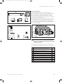
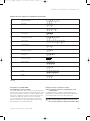
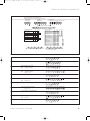
BS 5440–1 It is recommended that the fanned flue terminal should be positioned as follows:
a) at least 2m from an opening in the building directly
opposite, and
b) so that the products of combustion are not directly
directed to discharge across a boundary.
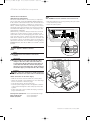
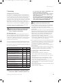
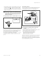
1) Dimensions B, C and D:
These clearances may be reduced to 25 mm without
affecting the performance of the boiler. In order to
ensure that the condensate plume does not affect
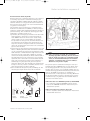
adjacent surfaces the terminal should be extended as
shown in fig. 3.8.
2) Dimension F:
This clearance may be reduced to 25 mm without
affecting the performance of the boiler. However, in
order to ensure that the condensate plume does not
affect adjacent surfaces a clearance of 300 mm is pre
ferred. For IE, recommendations are given in the current edition of IS 813.
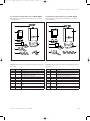
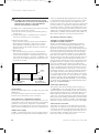
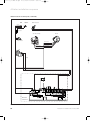
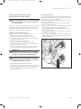
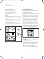
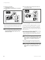
balcony/eaves
gutter
flue adequately
supported
flue extended to
clear any overhang
Fig. 3.8
3.9 Air supply
Detailed recommendations for air supply are given in BS
5440: Part 2.
It is not necessary to have an air vent in the room or
internal space in which the boiler is installed.
3.9.1 Cupboard or compartment ventilation
The boilers are very high efficiency appliances. As a consequence the heat loss from the appliance casing during
operation is very low. For cupboard or compartment
installations it is therefore not necessary to provide any
high or low level permanent air vents for cooling purposes.
3.10 Electrical supply
A 230 V, ~ 50 Hz single phase electricity supply fused to
3 Amp. must be provided in accordance with the latest
14
edition of BS7671 (IEE Wiring Regulations) and any other
local regulations that may apply. In IE reference should
be made to the current edition of the ETCI rules. The
method of connection to the mains electricity supply must
provide a means of completely isolating the boiler and
its ancillary controls. Isolation is preferably by the use of
a fused three pin plug and unswitched shuttered socket
outlet, both complying with the requirements of BS 1363.
Alternatively, a 3 Amp. fused doublepole switch with a 3
mm contact separation on both poles may be used.
This appliance must be earthed.
3.11 Guide to system requirements
3.11.1 Water circulation system
Detailed recommendations for the water circulation
system are given in BS 6798 and BS 5449: Part 1 (for
small bore and micro bore central heating systems).
Pipework not forming part of the useful heating surface
should be insulated to help prevent heat loss and possible freezing, particularly where pipes are run through
roof spaces and ventilated underfloor spaces. Draining
taps must be located in accessible positions which permit the draining of the whole system including the boiler
and the hot water system. Draining taps should be at
least 1/2 in. BSP nominal size and be in accordance with
BS 2879. The boiler is suitable for use with minibore or
microbore systems. Copper tubing to BS 2871: Part 1
should be used for water carrying pipework. All capillary
joints in all DHW pipework must be made with lead free
solder. Particularly where a new boiler is to be fitted to
an existing system, it is good practice that the system is
thoroughly cleansed. This cleansing should take place
prior to the fitting of the new boiler and be in accordance with BS 7593. For advice on the application of system
cleansers contact Sentinel, Betz Dearborn Ltd. Widnes,
Cheshire, WA8 8UD. Tel: 0151 495 1861, or Fernox, Alpha
Fry Technologies, Tandem House, Marlow Way, Croydon,
CR0 4XS. Tel 0870 6015000
3.11.2 Filling and make up
The system can be filled using the built in filling loop
(ecoMAX 800) or via a separate filling point fitted at a
convinient position on the heating circuit. The connection
must be removed when filling is completed. Where local
Water Authority regulation does not allow temporary
connection, a sealed system filler pump with break tank
must be used. The heating system will not be filled automatically from the domestic hot water side. (Alternative
methods of filling sealed systems are given in BS 5449).
3.11.3 Pressure relief valve
A pressure relief valve is provided with the boiler. This
safety device is required on all sealed C.H. systems and
is preset at 3 bar and provided with a 15 mm compression connection for a discharge pipe, which must be of no
less than 15 mm in diameter. The pressure relief valve
must not be used for draining purposes.
Instructions for installation and servicing ecoMAX