1
LINE THERMAL PRINTER
MODEL CBM-292/293
User’s Manual
CBM-292/293 User’s Manual
Declaration of Conformity
This printer conforms to the following Standards:
Low Voltage Directive 73/23/EEC, 93/68/EEC and the EMC Directive 89/336/EEC,
92/31/EEC, 93/68/EEC.
LVD : EN60950
EMC : EN55022
Class A
EN61000-3-2
EN61000-3-3
EN55024
This declaration is applied only for 230V model.
Warning:
This is a Class A products.
In a domestic environment this product may cause radio intereference
in which case the user may be required to take adequate measures.
CITIZEN is a registered trade mark of CITIZEN WATCH CO., LTD., Japan
CITIZEN es una marca registrada de CITIZEN WATCH CO., LTD., Japón
2
CITIZEN
CBM-292/293 User’s Manual
IMPORTANT SAFETY INSTRUCTIONS
•
•
•
•
•
•
•
•
•
•
•
•
•
Read all of these instructions and save them for later reference.
Follow all warnings and instructions marked on the product.
Unplug this product from the wall outlet before cleaning. Do not use liquid or aerosol cleaners. Use a
damp cloth for cleaning.
Do not use this product near water.
Do not place this product on an unstable cart, stand or table. The product may fall, causing serious
damage to the product.
Slots and openings on the cabinet and the back or bottom are provided for ventilation.
To ensure reliable operation of the product and to protect it from overheating, do not block or cover
these openings. The openings should never be blocked by placing the product on a bed, sofa, rug of
other similar surface. This product should never be placed near or over a radiator or heat register. This
product should never be placed near or over a radiator or heat register. This product should not be
placed in a built-in installation unless proper ventilation is provided.
This product should be operated from the type of power source indicated on the marking label. If you re
not sure of the type of power available, consult your dealer or local power company.
Do not allow anything to rest on the power cord. Do not locate this product where the cord will be
walked on.
If an extension cord is used with this product, make sure that the total of the ampere ratings on the
products plugged into the extension cord do not exceed the extension cord ampere rating. Also, make
sure that the total of all products plugged into the wall outlet does not exceed 15 amperes.
Never push objects of any kind into this product through cabinet slots as they may touch dangerous
voltage points or short out parts that could result in a risk of fire or electric shock. Never spill liquid of
any kind on the product.
Except as explained elsewhere in this manual, don’t attempt to service this product by yourself.
Opening and removing those covers that are marked “Do Not Remove” may expose you to dangerous
voltage points or other risks. Refer all servicing on those compartments to service personnel.
Unplug this product from the wall outlet and refer servicing to qualified service personnel under the
following conditions:
A. When the power cord or plug is damaged or frayed.
B. If liquid has been spilled into the product.
C. If the product has been exposed to rain or water.
D. If the product does not operate normally when the operating instructions are followed. Adjust only
those controls that are covered be the operating instructions since improper adjustment of other
controls may result in damage and will often require extensive work by a qualified technician to
restore the product to normal operation.
E. If the product has been dropped or the cabinet has been damaged.
F. If the product exhibits a distinct change in performance, indicating a need for service.
Please keep the poly bag which this equipment is packed in away from children or throw it away to prevent
children from putting it on. Putting it on may cause suffocation to them.
3
CITIZEN
CBM-292/293 User’s Manual
WICHTIGE SICHERHEITSANWEISUNGEN
•
•
•
•
•
•
•
•
•
•
•
Lesen Sie die nachfolgenden Anweisungen sorgfältig durch und bewahren Sie sie auf.
Befolgen Sie alle auf dem Drucker vermerkten Hinweise und Anweisungen. Vor dem Reinigen
grundsätzlich Stecker aus der Steckdose ziehen. Keine Flüssigkeiten oder Aerosolreiniger benutzen.
Nut mit einem feuchten Tuch abwischen.
Der Drucker darf nicht in der Nähe von Wasser aufgestellt werden.
Drucker nicht auf einem unstabilen Wagen, Stand oder Tisch aufstellen. Der Drucker könnte
herunterfallen und dabel beschädigt werden.
Schlitze und Öffnungen im Gehäuse, in der Rückwand und im Boden dienen der Belüftung. Sie dürfen
keinesfalls zugedeckt oder blockiert werden, da sich der Drucker sonst überhitzt. Drucker nicht auf ein
Bett, Sofa, Teppich oder dergleichen stellen. Drucker nicht in der Nähe eines Heizkörpers aufstellen.
Drucker darf nicht eingebaut werden, falls nicht für ausreichende Belüftung gesorgt ist.
Drucker nur mit der auf dem Typschild angegebenen Spannung betreiben. Wenn Sie sich nicht sicher
sind, fragen Sie ihren Händler oder ihr zuständiges Elektrizitätswerk.
Nichts auf das Stromanschlußkabel stellen. Kabel muß so verlegt werden, daß man nicht darauftreten
kann.
Ein etwaiges Verlängerungskabel muß der Stromstärke aller daran angeschlossenen Geräte entsprechen.
Keine Gegenstände in die Gehäuseschlitze schieben.
Drucker darf nur da gewartet werden, wo im Handbuch angegeben, Öffnen und. Abnehmen von
Abdeckungen, die mit “Do not remove” gekennzeichenet sind, könnte gefährliche spannungführende
Stellen oder sonstige Gefahrenpunkte freilegen. Die Wartung solcher Stellen darf grundsätzlich nur von
besonders ausgebildetem Fachpersonal vorgenommen werden.
A. Wenn das Stromanschlußkabel oder der Stecker beschädigt oder durch-gescheuert ist.
B. Wenn Flüssigkeit auf dem Drucker verschüttet wurde.
C. Wenn der Drucker im Regen gestanden hat oder Wasser darauf verschüttet wurde.
D. Wenn der Drucker trotz genauer Befolgung der Betriebsvorschriften nicht richtig arbeitet. Nur die in der
Bedienungsanleitung
angegebenen
Einstellungen
vornehmen.
Ein
Verstellen
anderer
Bedienungselemente könnte den Drucker beschädigen und macht umständliche Arbeiten eines
qualifizierten Technikers erforderlich, um den Drucker Wieder auf den normalen Betrieb einzustellen.
E. Wenn der Drucker heruntergefallen ist oder das Gehäuse beschädigt wurde.
F. Wenn der Drucker in seiner Leistung nachläßt.
Bitte halten Sie den Kunststoffbeutel, in den die Ware verpackt ist, von Kindern entfernt, oder werfen
Sie ihn weg, damit er nicht in die Hande von Kindern gerät. Das Überstülpen des Beutels kann zum
Ersticken führen.
Lärmemission kleiner 70dBA
4
CITIZEN
CBM-292/293 User’s Manual
IMPORTANT: This equipment generates, uses, and can radiate radio frequency energy and if not
installed and used in accordance with the instruction manual, may cause interference to radio
communications. It has been tested and found to comply with the limits for a Class A computing device
pursuant to Subpart J of Part 15 off FCC Rules, which are designed to provide reasonable protection
against such interference when operated in a commercial environment. Operation of this equipment in a
residential area is likely to cause interference, in which case the user at his own expense will be required to
take whatever measures may be necessary to correct the interference.
CAUTION: Use shielded cable for this equipment.
Sicherheitshinweis
Die Steckdose zum Anschluß dieses Druckers muß nahe dem Grät angebracht und leicht zugänglich sein.
For Uses in Canada
This digital apparatus does not exceed the class A limits for radio noise emissions from digital, apparatus,
as set out in the radio interference regulations of the Canadian department of communications.
Pour L’utilisateurs Canadiens
Cet appareil numérique ne dépasse pas les limites de carégorie a pour les émissions de bruit radio émanant
d’appareils numériques, tel que prévu dans les réglements sur l’interférence radio du départment Canadien
des communications.
5
CITIZEN
CBM-292/293 User’s Manual
<CAUTIONS>
1. Prior to using the equipment, be sure to read this User's Manual thoroughly. Please keep it handy for reference
whenever it may be needed.
2. The information contained herein may be changed without prior notice.
3. Reproduction of part or all of this User's Manual without permission is strictly prohibited.
4. Never service, disassemble, or repair parts that are not mentioned in this User's Manual.
5. Note that we will not be responsible for damages attributable to a user's incorrect operation/ handling or an
improper operating environment.
6. Operate the equipment only as described in this User's Manual; otherwise accidents or problems may result.
7. Data are basically temporary; they cannot be stored or saved permanently or for a long time.
Please note that
we will not be responsible for damages or losses of profit resulting from losses of the data attributable to
accidents, repairs, tests, and so on.
8. If you have any questions or notice any clerical errors or omissions regarding the information in this manual,
please contact our office.
9. Please note that, notwithstanding Item 8 above, we will not be responsible for any effects resulting from
operation of the equipment.
6
CITIZEN
CBM-292/293 User’s Manual
SAFETY PRECAUTIONS ----- BE SURE TO OBSERVE
In order to prevent hazards to an operator or other persons and damage to property, be sure to observe the
following precautions.
• The following describes the degrees of hazard and damages that can occur if the given instructions are
neglected or the equipment is incorrectly operated.
WARNING
Negligence of this precaution may result in death or serious injury.
CAUTION
Negligence of this precaution may result in injury or damage to property.
This is an illustration mark used to alert your attention.
This is an illustration mark used to indicate such information as an instruction or the like.
7
CITIZEN
CBM-292/293 User’s Manual
WARNING
•
•
•
•
•
•
•
•
•
•
•
•
Never handle the equipment in the following manners, as it may break, become out of order, or
overheat causing smoke and resulting in fire or electric shock.
If you find any damage, problem, smoke, or abnormal odor/sound, turn off the power, disconnect the
power cable, and contact your dealer. Never repair the equipment on your own - it is very dangerous.
Do not allow the equipment to receive a strong impact or shock, such as kicking, stomping, hitting,
dropping, and the like.
Install the equipment in a well-ventilated place. Do not use it in such a manner that its ventilation port
will be blocked.
Do not install the equipment in a place like a laboratory where chemical reactions are expected, or in a
place where salt or gases are contained in the air.
Use only power of the specified voltage and current capacity.
Do not connect/disconnect a power cord or a data cable, while holding the cable. Do not pull, install,
use, or carry the equipment in such a manner that force will be applied to the cables.
Do not drop or insert any foreign substances, such as clips or pins, into the equipment.
Do not put many loads on one electrical outlet.
Do not spill any liquid or spray any chemical-containing liquid over the equipment. If any liquid is
spilled on it, turn off the power, disconnect the power cable and power cord from the plug socket, and
so on, and contact our dealer.
Do not disassemble or remodel the equipment. Negligence of this may cause fire or electric shock.
An equipment packing bag must be discarded or kept away from children. A child can suffocate if the
bag is placed over the head.
8
CITIZEN
CBM-292/293 User’s Manual
PRECAUTIONS FOR INSTALLATION
•
•
•
•
•
•
•
•
•
•
•
•
•
•
•
•
•
Do not use or store the equipment in a place exposed to fire, moisture, or direct sunlight, or in a place
near a heater or a thermal device where the prescribed operating temperature and humidity are not met,
or in a place exposed to much oil, iron powder, or dust. The equipment may become out of order, emit
smoke, or catch fire.
Do not install the equipment in a place like a laboratory where chemical reactions are expected, or in a
place where salt or gases are contained in the air. There is a danger of fire or electric shock.
Firmly secure the equipment onto a flat and stable mounting panel free from vibrations and angled at 0°
to 90° in a well-ventilated place.
Do not install or use the equipment in a place where its operation could be hindered.
Do not place anything on the equipment, as it can lead to problems.
Use accessory fittings and screws to secure the equipment. Tighten the screws firmly and properly.
Excessive tightening can result in problems or damage.
Do not use the equipment near a radio or TV receiver. Do not share the power from a plug socket a
radio or TV receiver is connected to. It may cause a reception problem.
Use only power of the specified voltage and current capacity. Be careful not to mistake polarity. The
equipment may become out of order, emit smoke, or catch fire.
Confirm that a plug socket used for connection has sufficient capacity.
Avoid composite wiring with a power cable or excessively extended wiring. Excessive electric current
may cause heat generation/ignition of the supply line or shut off the power. Do not step on a cable or
use the equipment with excessive force (tension, load) applied to it.
Never connect a grounding cable to a gas pipe. There is a danger of explosion. When connecting or
disconnecting the grounding cable, be sure to disconnect the power plug from the plug socket.
When disconnecting/reconnecting the cables, be sure to turn off the power, including the mating side.
Connect a connector cable securely. If a reverse-polarity connection is made, internal elements may be
broken or a mating device may be adversely affected.
Avoid routing a signal line too long or connecting to any noisy device, to protect against such effects as
data deformation due to noise.
Use the equipment in an environment where there is a plug socket near the main body and you can
easily disconnect the power plug from it, to shut off the power.
Keep the equipment in the printing-head-up state when transporting the equipment or when it will not
be used for a long time.
When transporting the equipment, remove the rolled paper from it.
9
CITIZEN
CBM-292/293 User’s Manual
PRECAUTIONS FOR HANDLING
Do not handle the equipment in the following manners, because problems may result.
• Do not print without setting a roll of paper.
• Be careful not to drop foreign substances, such as clips, pins, and screws, into the main body.
• Do not spill any liquid or spray any chemical-containing liquid over the equipment.
• Do not stamp on, drop, hit, or give a strong shock to the equipment.
• Never use a pointed object, such as a pen, to operate the operation panel.
• Do not use Scotch tape to fasten paper together for continuous use.
• With the printing head down, never rotate the paper feed knob or force to pull the set roll of paper by
hand.
To Prevent Injury and Spreading of Damage
• Do not touch the printing part of the print head.
• When turning on the power, do not touch the moving parts, such as a cutter and gear inside the main body,
or electric parts.
• Be careful to avoid bodily injure or damaging other objects with an edge of sheet metal.
• Should any error occur while operating the equipment, stop it immediately and disconnect the power plug
from the plug socket.
• Should a problem occur, leave solving it to our serviceman. Do not disassemble the equipment on your
own.
• When opening/closing the panel, and so on, be careful not to catch your hand or finger on the equipment.
10
CITIZEN
CBM-292/293 User’s Manual
DAILY MAINTENANCE
•
•
•
•
Prior to starting maintenance work, be sure to turn off the main body.
When cleaning the platen roller, dip a cotton swab in ethyl alcohol and wipe off dust and stain.
Use a dry soft cloth to wipe off stains and dust from the surfaces of the main body case. For severe
soiling, dip the cloth in water and wring it, for wiping off the soil. Never use organic solvents, such as
alcohol, thinner, trichlene, benzene, ketone, or chemical dusters.
If the equipment is contaminated with paper powder, use a soft brush to clean it.
CAUTION:
The printing head and motor are very hot. Do not touch them immediately
after printing.
11
CITIZEN
CBM-292/293 User’s Manual
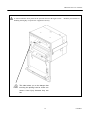
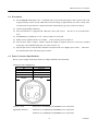
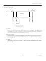
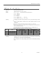
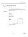
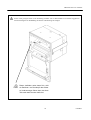
A caution label has been pasted to the position shown in the figure below.
Read the precautions for
handling thoroughly, to operate the equipment correctly.
This label alerts you to the danger that
touching the printing head or motor can
cause a burn injury because they are
hot.
12
CITIZEN
CBM-292/293 User’s Manual
CONTENTS
1. OUTLINE............................................................................................................................................................. 16
1.1
Features..................................................................................................................................................................... 16
1.2
Accessories ............................................................................................................................................................... 16
2. BASIC SPECIFICATIONS ................................................................................................................................ 17
2.1
Model Classifications................................................................................................................................................ 17
2.2
Service Power Source ............................................................................................................................................... 17
2.3
Basic Specifications .................................................................................................................................................. 18
2.4
Paper Specifications.................................................................................................................................................. 19
2.4.1 Recommanded Paper ......................................................................................................................................... 19
2.4.2 Printing Position ................................................................................................................................................ 19
2.4.3 Printing Head and Cutter Layout ....................................................................................................................... 19
OUTER APPEARANCE AND COMPONENT PARTS................................................................................. 20
3.
3.1
Outer Appearance and Component Parts .................................................................................................................. 20
3.2
Description of Component Parts ............................................................................................................................... 21
4. OPERATION ....................................................................................................................................................... 22
4.1
Mounting onto the Rack............................................................................................................................................ 22
4.2
Connecting the Power and Data Cable...................................................................................................................... 23
4.3
Opening/Closing the Front Cover ............................................................................................................................. 24
4.4
Feeding the Paper...................................................................................................................................................... 24
4.5
Auto Loading Function ............................................................................................................................................. 24
4.6
Setting the Printing Paper ......................................................................................................................................... 25
4.7
Remedies for Paper Jam and Cutter Lock................................................................................................................. 26
4.8
Self-printing Function ............................................................................................................................................... 26
4.9
PE and Alarms .......................................................................................................................................................... 27
4.9.1 Paper End (PE) .................................................................................................................................................. 27
4.9.2 Alarms ............................................................................................................................................................... 27
4.10
Power Supply Method and Connection .................................................................................................................. 28
5. DIP SWITCH SETTING .................................................................................................................................... 29
6. CONNECTORS ................................................................................................................................................... 30
6.1
Connector's Pin Configurations ................................................................................................................................ 30
13
CITIZEN
CBM-292/293 User’s Manual
6.2
Precautions................................................................................................................................................................ 31
6.3
Power Connector Specifications ............................................................................................................................... 31
7. PARALLEL INTERFACE.................................................................................................................................. 32
7.1
Specifications............................................................................................................................................................ 32
7.2
Input and Output Signals .......................................................................................................................................... 32
7.3
Electrical Characteristics........................................................................................................................................... 32
7.4
Timing Chart ............................................................................................................................................................. 33
7.5
Data Receiving Control............................................................................................................................................. 33
7.6
Buffering ................................................................................................................................................................... 33
8. SERIAL INTERFACE ........................................................................................................................................ 34
8.1
Specifications............................................................................................................................................................ 34
8.2
Input and Output Signals .......................................................................................................................................... 35
8.3
Data Configuration.................................................................................................................................................... 36
8.4
Error Detection ......................................................................................................................................................... 37
8.5
Data Receiving Control............................................................................................................................................. 37
8.6
Buffering ................................................................................................................................................................... 37
8.7
Electrical Characteristics........................................................................................................................................... 38
9. MAINTENANCE AND SERVICE .................................................................................................................... 39
10. PRINT CONTROL FUNCTIONS...................................................................................................................... 40
10.1
Commands List....................................................................................................................................................... 40
10.2
Command Details ................................................................................................................................................... 41
10.2.1 Description of Items ............................................................................................................................................ 41
10.2.2 Command Details................................................................................................................................................ 42
11. CHARACTER CODES TABLE ......................................................................................................................... 82
11.1
International............................................................................................................................................................ 82
11.2
Domestic................................................................................................................................................................. 83
11.3
International Character Codes Table....................................................................................................................... 84
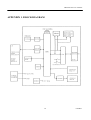
APPENDIX 1.
BLOCK DIAGRAM..................................................................................................................... 85
APPENDIX 2.
OUTLINE DRAWING ................................................................................................................. 86
14
CITIZEN
CBM-292/293 User’s Manual
<<< German >>>
4. BETRIEB ..............................................................................................................................................................95
4.1
Befestigung auf einem Gestell.................................................................................................................................. 95
4.2
Nets-und Datenkabelanschluß .................................................................................................................................. 96
4.3
Öffnen/Schließen der Frontabdeckung ..................................................................................................................... 97
4.4
Papiervorschub ......................................................................................................................................................... 97
4.5
Automatischer Papiereinzng ..................................................................................................................................... 97
4.6
Einlegen des Druckpapiers ....................................................................................................................................... 98
4.7
Beseitigung von Papierstans ..................................................................................................................................... 99
4.8
Selbstdruck funktion................................................................................................................................................. 99
4.9
PE und Alarm ........................................................................................................................................................... 99
4.9.1 Papierende (PE)................................................................................................................................................. 99
4.9.2 Alarm............................................................................................................................................................... 100
4.10
Betriebsstromversorgung und Anschluß............................................................................................................... 101
5. EINSTELLUNG DER DIP-SCHALTER .........................................................................................................102
9. WARTUNG UND KUNDENDIENST ..............................................................................................................103
15
CITIZEN
CBM-292/293 User’s Manual
1. OUTLINE
The CBM-292/293 is a rack mountable thermal panel printer. It is widely applicable to various kinds of data
communication terminals, POS terminals, measuring terminals, and others.
This small-size printer is provided with abundant features. It is available for different applications. Prior to using it, read this
manual thoroughly for full understanding and safe operation.
1.1 Features
1.
Rack mountable small-size line thermal printer.
2.
High speed and low noise.
3.
Long-life printing head used and high reliability due to a simple mechanism.
4.
Serial/parallel interface selectable by a DIP switch.
5.
Built-in input buffer.
6.
Capable of printing the bar code(with a special command).
7.
Provided with an auto cutter(CBM-293 only).
8.
Capable of registering the external characters(up to 94 of them).
9.
Runs on two types of power sources; external power source and accessory AC adapter.
1.2 Accessories
When unpacking the printer, confirm that the following parts are included in the package.
Printer body................................... 1 unit
Sample paper roll .......................... 1 piece
Power and data cable .................... 1 piece
Fitting............................................ 1 piece
Fitting setscrews............................ 2 pieces
Wire clamp .................................... 1 piece
AC adapter .................................... 1 piece (AC adapter-specific model only)
(30AD or 31AD)
Power cable................................... 1 piece (AC adapter-specific model only)
User's manual ................................ 1 copy
16
CITIZEN
CBM-292/293 User’s Manual
2. BASIC SPECIFICATIONS
2.1 Model Classifications
CBM-292
48
F
Model Name
120
[
-
(
)]
Auxiliary Function
292: Without Auto Cutter
Added
293: With Auto Cutter
Depending
on
Specifications
Printing Digits
48: 48 colums (Font A)
(Mechanism: LT381 Used)
AC Adaptor Voltage
120: 120V AC
230: 230V AC
DC: 24V DC (Without AC Adaptor)
Character Set
F: International
2.2 Service Power Source
Use the accessory AC adapter (30AD or 31AD).
17
CITIZEN
CBM-292/293 User’s Manual
2.3 Basic Specifications
Item
Description
Printing method
Printing speed
Dot density
Printing columns
Character size
Line Thermal Dot Printing
62.5 mm/sec. At maximum
8 dots/mm (Horizontal and Vertical)
Font A: 48 columns, Font B: 64 columns
Font A: 1.25 mm × 3.00 mm (10 × 24 + 2 dots space),
Font B: 0.88 mm × 2.13 mm (7 × 17 + 2 dots space),
Character types
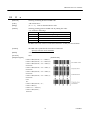
Alphenumerals, international characters
Bar code types
UPC-A/E, JAN(EAN) 13 columns/8 columns, ITF, CODE 39, CODE 128,
CODABAR
Line spacing
4.23 mm (1/6 inch), settable by a command
Paper
Thermal paper roll: 80 mm × φ50 mm(Max)
Interface
Parallel (CENTRONICS) or serial (RS-232C)
Selectable by a DIP Switch.
Input buffer
3 KB
Paper end detection
Equipped (Stops printing when the paper runs out.)
Auto loading
Equipped (If new paper is set into the paper inlet, it will be fed
automatically.)
Auto cutter (CBM-293 only)
Cuts the paper automatically by a command. Either full cut or partial cut
is selectable.
International character set
Capable of setting the following 10 countries for specific character codes
by a command.
(U.S.A., Frence, Germany, U.K., Denmark I and II, Sweden, Italy, Spain,
Japan, Norwey)
Supply voltage and power 24V DC +/-7%.
Standby: Approx. 0.2A,
consumption
Printing: Approx. 1.8A (Ave) / Peak: Approx. 6A
Rated input: 100 ∼ 240V AC, 50/60 Hz, 120VA
AC adapter(30AD/31AD)
Rated output: 24V DC, 1.8A
Operating temperature
5 ∼ 40 °C, 35 ∼ 85 % RH (No dew condensation)
Storage temperature
-20 ∼ 60 °C, 10 ∼ 90 % RH (No dew condensation)
Outer dimensions
126 (W) × 109 (H) × 99 (D) mm
Weight
CBM-292: Approx. 500g (Main body only)
CBM-293: Approx. 670g (Main body only)
Mounting Braket: Approx. 53g
AC adapter: Approx. 430g
Applicable standards ∗1
UL, CUL, TÜV (GS)
EMI ∗1
VCCI: Class A applicable, FCC: Class A applicable
Printing head life:
Pulse resistance --- 50,000,000 pulses (Print ratio: 12.5 %),
Reliability
Wear resistance --- 30km (With specified paper at normal
temperature and humidity)
Auto cutter life: 300,000 cuts (CBM-293)
∗1: Applicable when the accessory AC adapter is used.
18
CITIZEN
CBM-292/293 User’s Manual
2.4 Paper Specifications
2.4.1
Recommended Paper
Type
: Thermal paper
Paper width
: 80 plus 0 / minus 1 mm
Paper thickness
: 65 plus 5 / minus 5µm
Roll diameter
: φ50 mm(Max)
Printing surface
: Outside of the roll(Surface)
Recommended paper
: TF50KS-E2C by Nippon Seishi, or its equivalent
Core
: φ12 mm(Inner diameter), φ18 mm(Outer diameter)
CAUTION :
1. User the paper which has not been pasted to the core.
2. Note that if the paper comes into contact with a chemical or oil, it may discolor or lose the
printed record.
3. Note that if the paper is rubbed strongly with a nail or hard metal, it may discolor.
4. Discoloring will start at about 70°C.
Watch out fully for effects of the heat, moisture,
light, etc.
2.4.2
Printing Position
2.4.3
Printing Head and Cutter Layout
19
CITIZEN
CBM-292/293 User’s Manual
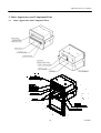
3. Outer Appearance and Component Parts
3.1
Outer Appearance and Component Parts
20
CITIZEN
CBM-292/293 User’s Manual
3.2
Description of Component Parts
• Front cover
Open and close the front cover when replacing the paper roll or the paper is jamming.
• PAPER lamp
Illuminated when the paper is running out.
• FEED switch
Press this switch when you want to feed the paper. The paper is fed while the switch is pressed.
If the power is turned on with the switch held down, the printer will perform self-printing.
• Mechanism lock lever
Used to lower the mechanism when raising the printing head, when the paper is jamming or the auto
cutter is being locked, or when manually discharging the paper or operating the cutter blade.
• Printing head up lever
Used to raise the printing head.
The printing head has been kept up upon shipment.
• Roll paper cutting blade (CBM-292 only)
Used to cut the paper.
• Fitting metals
Used to fix the main body to the rack, etc.
• Interface connector
Connects the accessory data cable.
Provides serial/parallel communications.
• DIP switch
Used to initially set communication(serial/parallel), printing concentration, etc.
• Power connector
Connects the accessory AC adapter(power source).
• FG terminal
Earth terminal for the main body frame.
Wire as required.
• Auto cutter (CBM-293 only)
Automatically cuts the roll paper by a command.
21
Either partial cut or full cut is selectable.
CITIZEN
CBM-292/293 User’s Manual
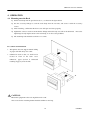
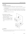
4. OPERATION
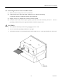
4.1 Mounting onto the Rack
(1) Fit the main body into the specified rack, etc., as shown in the figure below.
(2) Use the accessory fittings to catch the main body from the rear side, and secure it with the accessory
screws.
(3) After mounting, confirm that the front cover will open and close properly.
(4) Tighten the screws to such an extent that the fittings and main body case will not be deformed.
Excessive
tightening not only imparts stress to the main body, it can also cause problems.
(5) The mounting rack should be as thick as 1 to 3 mm.
Precautions for Installation
• This printer does not support natural falling
of paper with full cut by auto cutter.
• Obstruction such as door, etc. shall not be
located in front of the front cover.
Otherwise, paper ejection is obstructed
resulting in paper jam or the like.
CAUTION:
Mount the equipment to the rack angled from 0° to 90°.
The screws for the mounting braket should be within 15 mm long.
22
CITIZEN
CBM-292/293 User’s Manual
4.2 Connecting the Power Source and Data Cable
(1) Make sure that the main power source is turned off.
(2) Connect the accessory data cable firmly, making sure of its direction and wiring.
A connecting position is located on the back of the main body.
(3) Plug the accessory AC adapter into a connector until it is locked.
(4) Ground the frame of the main body as required, to prevent noise, static electricity, and so on.
Secure a
grounding conductor firmly to the ground terminal on the back, using a screw.
CAUTION :
•
Note that the main body is turned on by plugging in an AC cord.
•
Never connect the grounding conductor to a gas pipe.
•
When disconnecting / reconnecting the cable, hold it by the base, as it can snap if held by the cable itself.
23
CITIZEN
CBM-292/293 User’s Manual
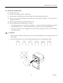
4.3 Opening/Closing the Front Cover
(1) Put your finger in the left and right concavities of the front cover, and pull in the arrow-indicated direction.
The front cover opens about 180 ° downward.
(2) When closing the front cover, hold and close it firmly.
not slackened.
When closing, make sure that the roll of paper is
If closed with the paper slackened, it could jam.
CAUTION:
When opening the front cover, hold it firmly; because it opens about 180 °, it can break when opened.
4.4 Feeding the Paper
Press the FEED switch on the right panel of the front cover once.
is also fed while pressing the switch.
FEED switch.
The paper is fed by one line.
When you want to feed the paper, do not pull it by force.
The paper
Use the
Even if the front cover is opened or the mechanism is lowered, pressing the switch feeds the
paper, but it could cause a paper jam.
CAUTION:
Do not press the switch with a pointed object, as it can cause problems.
4.5 Auto Loading Function
The equipment is provided with a function to automatically load a roll of paper into the main body.
If the roll
of paper is brought to the paper inlet of the printer mechanism, it will be automatically fed by a constant
amount.
CAUTION:
Note that pulling the paper can cause a paper jam or insertion miss.
24
CITIZEN
CBM-292/293 User’s Manual
4.6 Setting the Printing Paper
(1) Open the front cover.
(2) Cut the end of the paper almost at a right angle.
(3) Check the paper winding direction, and set the paper in the paper holder inside the case.
(4) Insert the end of the paper straight into the paper inlet of the printer mechanism.
The paper will be
automatically inserted.
(5) Remove slack from the paper, and close the front cover.
(6) Press the FEED switch to feed the paper as required.
* The printing head is kept up at the time of shipment.
the printing-head-up state.
The paper cannot be automatically inserted in
Shift the head up lever to the near side, to lower the printing head.
* Note that if there are data remaining in the printer buffer, printing will start after auto-loading
(automatic insertion).
CAUTION:
•
If the set paper is slanted or not properly fed, move up the printing head, remove the paper gently, and
insert it again.
•
When replacing the paper, move up the printing head and pull out the remaining paper gently.
25
CITIZEN
CBM-292/293 User’s Manual
4.7 Remedies for Paper Jam and Cutter Lock
If the paper jams or the auto cutter is locked, follow the procedure below to eliminate the cause.
For your
safety, be sure to turn off the power prior to starting the work.
(1) Open the front cover.
(2) Press the mechanical lock lever inward, to lower the mechanism.
(3) Eliminating a paper jam.
Eliminate all the jamming paper carefully and gently.
When pulling out the
paper from the printer mechanism, move up the printing head and pull it out gently.
(4) Unlocking the cutter.
Eliminate the paper from the cutter section, and turn on the power.
Cutter
unlocking operation will be completed if the cutter blade returns and the initial operation is performed.
If the cutter blade does not return or an error recurs, turn off the power, and turn the left inner knob of the
cutter toward the far side, as shown in the figure below.
caught paper gently.
Since the cutter blade withdraws, eliminate the
Then, turn on the power and confirm that the initial operation is performed.
(5) After eliminating the cause, raise the mechanism back to its home position, return the head up lever, and
turn on the power again.
CAUTION :
•
Never work with the printing head or motor immediately after printing, as they are hot and can burn you.
If such work is unavoidable, never touch them directly.
•
Be careful to avoid injury by the metal edges.
4.8 Self-Printing Function
The characters used, ROM version, and DIP switch information are printed by turning on the power with the
FEED switch held down or inputting a RESET signal.
If the auto-cutter is attached, the paper will be cut after
printing.
26
CITIZEN
CBM-292/293 User’s Manual
4.9 PE and Alarm
4.9.1
Paper End (PE)
The equipment detects if paper is still available.
If the paper has run out, it will stop printing, output
BUSY (DTR) and PE, and turn on the PAPER lamp.
If the paper is set, the signals will be canceled and the PAPER lamp will be turned off.
cancellation, the equipment starts printing or waits for data entry.
After signal
If the paper has run out, but there are
still some data remaining in the buffer, printing will be resumed after setting new paper.
4.9.2
Alarms
If the auto-cutter is locked, the printing head is up, the printing head temperature is increasing, or there is
a certain failure, such as a paper jam, the equipment will halt printing, turn off the power for the motor
and printing head, and output BUSY (DTR), ERROR, and FAULT (Parallel only) to the host.
ERROR output can directly connect to an LED.
•
Error at power-on
The following faults are also possible, but a memory error has occurred.
Turn off the power and
contact your dealer.
•
When the auto-cutter is locked or the paper is jamming
Turn off the power and eliminate the fault.
because the power has been turned off.
When this is done, the data in the buffer are erased
Do not eliminate the fault with the power left on.
To
reset, turn on the power again after eliminating the fault.
•
When the printing head is up
Shift the head up lever to the near side.
•
The printing head is lowered, to enable printing.
When the printing head temperature is increasing
If a large amount of data has been printed, such as in continuous printing, etc., the printing head
temperature will increase.
If this is the case, printing will stop, to protect the printing head.
While printing is halted, various operations (paper feed, etc.) are not available.
printing head temperature to drop.
enabling printing.
Wait for the
After a while the printing head temperature will drop,
If there are still some data remaining in the buffer, printing will be resumed.
CAUTION:
Never work with the printing head or motor immediately after printing, as they are hot and can burn you.
If such work is unavoidable, never touch them directly. Be fully careful of static electricity.
27
CITIZEN
CBM-292/293 User’s Manual
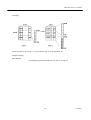
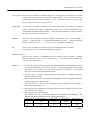
4.10 Power Supply Method and Connection
The power is generally supplied via an AC adapter.
If you use an interface cable (accessory cable) to supply
the power, connect the cable as follows:
(1) Connect the accessory cable to the external power source.
Pin No.
Signal Name
Input/Output
Function
7, 8, 9, 10, 11, 12
V24
−
Power source (+24 V)
13, 14, 15, 16, 17, 18
GND
−
Power source (GND)
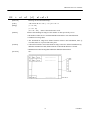
(2) Remove the rear cover, to reveal the control board.
Short-circuit the Jumper(J9, Marked by silk print).
ΟΟ
J9
CN5
Control Board
Short-circuit
CAUTION:
If the power is supplied via the accessory cable, never connect the AC adapter.
28
CITIZEN
CBM-292/293 User’s Manual
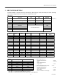
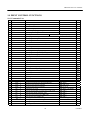
5. DIP SWITCH SETTING
The DIP switch(DS1) is located on the back of the main body. When setting the switch, turn off the power for the main body.
If the setting is changed with the power turned on, it will not become valid.
DIP Switch
Setting upon
Function
ON
OFF
Shipment
292(OFF)
DS1- 1
Auto cutter
Yes
No
ON
2
CR switching
LF operated
Ignored
OFF
3
Printing density
Standard
Dark
OFF
4
DTR-DSR/XON-XOFF
XON−XOFF
DTR−DSR
OFF
5
Interface
6
″
7
″
8
″
OFF
OFF
See the table below
OFF
OFF
Interface
DS1-8
DS1-7
DS1-6
DS1-5
OFF
OFF
OFF
OFF
OFF
OFF
OFF
OFF
ON
OFF
ON
OFF
OFF
OFF
ON
ON
OFF
ON
OFF
OFF
OFF
ON
OFF
ON
OFF
ON
ON
OFF
OFF
ON
ON
ON
ON
OFF
OFF
OFF
ON
OFF
OFF
ON
ON
OFF
ON
OFF
ON
OFF
ON
ON
ON
ON
OFF
OFF
ON
ON
OFF
ON
ON
ON
ON
OFF
ON
ON
ON
ON
Parity
Parallel input
Serial input
″
″
″
″
″
″
″
″
″
″
″
″
″
″
The main body has been preset with jumpers upon shipment.
Jumper
J1
J2
J3
J4
J5
J6
J7
J8
Domestic Spec.
Open
Open
Open
Short
Short
Short
Short
Short
International Spec.
Short
Short
Short
Short
Short
Short
Short
Short
−
None
″
″
″
″
−
1,200
2,400
4,800
9,600
19,200
Odd
1,200
″
″
″
″
2,400
4,800
9,600
19,200
Even
1,200
″
″
″
″
2,400
4,800
9,600
19,200
1. Domestic Specifications
• International characters
• Kanji
• Auto loading function
• Input buffer
• Serial communication bit length
2. International Specifications
• International characters
• Auto loading function
• Input buffer
• Serial communication bit length
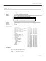
* The DS1-4 is invalid if parallel input is specified.
* The DS1-1 results in an error if set to ON in case of the CBM-292.
29
Baud Rate
(bps)
: Japan
: JIS code
: 3 KB
: 8 bits
: U.S.A.
: 3 KB
: 8 bits
CITIZEN
CBM-292/293 User’s Manual
6. CONNECTORS
The following lists the wiring of the accessory data cable.
Be sure to wire correctly, observing the connecting
direction and position.
6.1 Connector's Pin Configurations
Pin No.
Signal
I/O
Function
1∼3, 7∼18
−
−
Unused (Unavailable)
4∼6
GND
−
Circuit common GND
19
−
−
Unconnectable
20
ERROR
Output
ERROR LED output (Directly connectable)
21
−
−
Unconnectable
22
DTR
Output
Serial interface DTR
23
TXD
Output
Serial interface TXD
24
RXD
Input
Serial interface RXD
25
DSR
Input
Serial interface DSR
26
STB
Input
Parallel interface STROBE
27
BUSY
Output
Parallel interface BUSY
28
ACK
Output
Parallel interface ACK
29
DATA0
Input
Parallel interface DATA0
30
DATA1
Input
Parallel interface DATA1
31
DATA2
Input
Parallel interface DATA2
32
DATA3
Input
Parallel interface DATA3
33
DATA4
Input
Parallel interface DATA4
34
DATA5
Input
Parallel interface DATA5
35
DATA6
Input
Parallel interface DATA6
36
DATA7
Input
Parallel interface DATA7
37
PE
Output
Parallel interface PE
38
FAULT
Output
Parallel interface FAULT
39
RESET
Input
Parallel interface RESET
40
−
−
Unconnectable
Connector used: LY20-40P-DT1-P5 (Made by JAE)
Applicable connector: LY10-DC40 (Made by JAE)
* The No. 19 and 21 pins are internally used; do not connect them externally.
CAUTION:
•
Wrong wiring damages not only the main body, but the opponent host.
•
Never connect the unconnectable pins because it may cause the main body to have a trouble or
malfunction.
30
CITIZEN
CBM-292/293 User’s Manual
6.2 Precautions
(1) For the ERROR LED output, 330Ω is included in the circuit of the main body so that a current value will
be approximately 10mA. Use the LED whose forward voltage is approximately 2V. If the current value
exceeds 10mA in operation, the control board of the main body may go out of order or be broken.
(2) Connect all grounding conductors.
(3) The serial interface is equipped with a RS-232C driver and receiver.
Be sure to use at the RS-232C
level.
(4) The RESET pin is pulled up at 3.3kΩ. Do not connect it if not used.
(5) Either serial or parallel interface is available.
If not necessary, do not connect it.
(6) The accessory cable is approx. 300mm. Adjust the length as required. However, excessively extended
wiring may cause malfunctioning due to an effect of noise, etc.
(7) Only the pins for the serial interface should be connected to the 5V or higher power source.
Otherwise,
the control board of the main body may be broken.
6.3 Power Connector Specifications
This is a power supply connector from the AC adapter attached to the main body.
Connector's Pin Configurations
No.
Function
1
2
3
SHELL
+24V
GND
N.C
FG
Connector used
: TSC7960-53-2010(Made by HOSHIDEN) or its equivalent
Applicable connector
: TSC8927-63-1100(Made by HOSHIDEN) or its equivalent
TSC8927-53-1100(Made by HOSHIDEN) or its equivalent
31
CITIZEN
CBM-292/293 User’s Manual
7. PARALLEL INTERFACE
7.1 Specifications
Data input system
: 8-bit parallel system(DATA0 ∼ 7)
Control signals
: ACK, BUSY, STROBE, FAULT, PE, RESET
7.2 Input and Output Signals
• DATA0 ∼ 7
: An 8-bit parallel signal.(Positive logic)
• STROBE
: A strobe signal to read the 8-bit data.(Negative logic)
• RESET
: A signal to reset the entire control board.(Negative logic)
• ACK
: An 8-bit data request signal.
A pulse signal to be output at the end of the BUSY signal.(Negative logic)
• BUSY
: A signal to indicate the BUSY status. Input new data when "LOW."
(Positive logic)
• FAULT
: A signal turned to "LOW" in case of the alarm status.(Negative logic)
• PE
: A signal to be output when the printing paper runs out.(Positive logic)
7.3 Electrical Characteristics
(1) Input signal levels
"HIGH" level
: 0.7Vcc at minimum
"LOW" level
: 0.3Vcc at maximum
(2) Output signal levels
"HIGH" level
: Vcc-0.1V at minimum
"LOW" level
: 0.1V at maximum
(3) Input/output conditions
The STROBE and RESET input signals are all pulled up at 3.3kΩ.
[Printer Side]
The others are pulled up at 50kΩ.
[Host Side]
All the output signals are pulled up at 50kΩ.
32
CITIZEN
CBM-292/293 User’s Manual
7.4 Timing Chart
The following chart shows the data input and printing timings.
Supply
T1, T2, T3
0.5µs MIN
T4
270ns MAX
T5
2.3µs TYP
T6
500ms MIN (At power-on)
7.5 Data Receiving Control
When the BUSY signal is at "LOW," the data can be received from the host, but when at "HIGH," it cannot be
received.
7.6 Buffering
The main body has a 3KB input buffer.
The host side is immediately released because a large amount of
data can be buffered.
33
CITIZEN
CBM-292/293 User’s Manual
8. SERIAL INTERFACE
8.1 Specifications
(1) Synchronizing system
:
Asynchronous
(2) Baud rate
:
1,200, 2,400, 4,800, 9,600, or 19,200 bps (User selectable)
Start bits
:
1 bit
Data bits
:
8 bits
Parity bits
:
Odd, even, or no parity (User selectable)
Stop bits
:
1 bit or more
(3) Configuration of one word
(4) Signal polarity
RS-232C
• Mark
= Logic "1"(−3 ∼ −12 V)
• Space
= Logic "0"(+3 ∼ +12 V)
(5) Received data (RXD signal)
RS-232C
• Mark
= 1
• Space
= 0
(6) Reception control (DTR signal)
• Mark
:
Data transfer disabled (BUSY)
• Space
:
Data transfer enabled
(7) Transmitted data (TXD signal)
• Mark
= 1
• Space
= 0
(8) Transmission control (DSR signal)
• Mark
:
TXD data transmission disabled
• Space
:
TXD data transmission enabled
(9) Transmission control (TXD signal: X-ON/X-OFF control)
• DC1 code(11H) X-ON
:
Data reception enabled
• DC3 code(13H) X-OFF
:
Data reception disabled
34
CITIZEN
CBM-292/293 User’s Manual
8.2 Input and Output Signals
(1) TXD
If the input buffer on the printer side has 128 or less remaining bytes while receiving the data, the
DC3(13h) data reception disabled signal will be output.
If the input buffer has 256 or more remaining
bytes, the DC1(11H) data reception enabled signal will be output to the host side.
At the time of
sending the status information, if DTR/DSR control is selected, the data will be sent after confirming that
DSR is Space.
If DTR/DSR is not selected, the data will be sent, ignoring DSR.
(2) RXD
A serial received data signal.
If there is a framing error, overrun error, or parity error, that data will be
printed as "?".
(3) DTR
When this signal is Space, write a data or command.
will result, ignoring the data.
If written at Mark time(BUSY), an overrun error
The data can be written in the input buffer even during printing.
Mark(BUSY) will be generated at power-on, during test printing, at on-line mode, or at reset time as
well.
(4) DSR
Set to Space when sending the data from the printer to the host in printer status transmission.
When set
to Mark, the printer will wait to transmit until the Space status takes effect, without transmitting the data.
Ignored in case of X-ON/X-OFF control.
(5) GND
A signal line at the same level as the GND for the circuit driving power.
35
CITIZEN
CBM-292/293 User’s Manual
8.3 Data Configuration
Mark
b0, b1, b2 ....
Space
1
2
1.
Start Bit
2.
Data Bits(+ Parity Bit)
3.
Stop Bits (1 or More)
3
(1) Start bit
When a 1/2 bit passes from a fall edge of Mark to Space, the status is read again.
be recognized as the start bit.
If it is Space, it will
If it is Mark, it will not be recognized as the start bit.
An attempt to
detect the start bit will be made again without taking it as an error.
(2) Data bits + parity bit
The data is sampled at 1 bit worth of time from the 1/2 start bit and the then status is taken as the data for
the relevant bit.
The bits are arranged in order of Bit 0, Bit 1,..., Parity Bit, counting from the one
closest to the start bit.
(3) Stop bit
The stop bit is the Mark level of 1 bit or more.
If Space is detected at stop bit detection time, a framing
error will result.
36
CITIZEN
CBM-292/293 User’s Manual
8.4 Error Detection
Errors detected include parity error, framing error, and overrun error.
(1) Framing error
If the Space status is detected at stop bit detection time, an error will result and that data will be stored in
the input buffer as "?".
(2) Parity error
If a parity check has been specified and an error is detected in the parity check, that data will be stored in
the input buffer as "?".
(3) Overrun error
If an overrun error is detected, that data will be stored in the input buffer as "?".
8.5 Data Receiving Control
If DTR/DSR control has been selected and the DTR signal is at "LOW," the data will be received from the
host.
If at "HIGH," it cannot be received.
If DTR/DSR control has not been selected, the data will be
received from the host after sending X-ON, but it cannot be sent after sending X-OFF.
8.6 Buffering
There are TxD and DTR signals as control signals for data transfer to the input buffer.
(1) TXD signal (See 8.2 (1))
(2) DTR signal (See 8.2 (3))
37
CITIZEN
CBM-292/293 User’s Manual
8.7 Electrical Characteristics
(1) RS-232C circuit
Input (RXD, DSR)
[Printer Side]
[Host Side]
Mark=(-8V): Stop bit
RXD
Space=(+8V): Start bit
Equivalent MAX202
DSR
Mark=(-8V):
Transmission Disabled
Space=(+8V):
Transmission Enabled
Output (DTR, TXD)
Equivalent MAX202
Mark=(−8V): At Busy
DTR
Space=(+8V): At Ready
Mark=(−8V): 1
TXD
38
Space=(+8V): 0
CITIZEN
CBM-292/293 User’s Manual
9. MAINTENANCE AND SERVICE
For the information on maintenance and service, please contact our dealer.
39
CITIZEN
CBM-292/293 User’s Manual
10. PRINT CONTROL FUNCTIONS
10.1 Commands List
Control Code
1
2
3
4
5
6
7
8
9
10
11
12
13
14
15
16
17
18
19
20
21
22
23
24
25
26
27
28
29
30
31
32
33
34
35
36
37
38
39
40
41
42
HT
LF
CR
ESC SP
ESC !
ESC %
ESC &
ESC ∗
ESC −
ESC 2
ESC 3
ESC =
ESC @
ESC D
ESC E
ESC G
ESC J
ESC R
ESC V
ESC a
ESC c3
ESC c4
ESC c5
ESC d
ESC i
ESC m
ESC p
ESC t
ESC u
ESC v
ESC {
ESC $
ESC ¥
GS
k
GS
w
GS
h
GS
H
GS
f
GS ∗
GS
/
GS
:
GS
^
Function
Code
Horizontal tab
09H
Printing and paper feed
0AH
Print
0DH
1BH 20H n
Setting the right space amount of the character
Collective specifying printing mode
1BH 21H n
Specifying/canceling download character set
1BH 25Hn
Defining download characters
1BH 26H 5 n m[a p1 p2 ... psxa]m-n+1
Specifying the bit image mode
1BH 2AH mn1n2[d]k
Specifying/canceling underline
1BH 2DH n
Specifying 1/6-inch line feed rate
1BH 32H
Setting line feed rate of minimum pitch
1BH 33H n
Data input control
1BH 3DH n
Initializing the Printer
1BH 40H
Setting horizontal tab position
1BH 44H [n]k00H
Specifying/canceling highlighting
1BH 45H n
Specifying/canceling double printing
1BH 47H n
Printing and feeding paper n/203 inch
1BH 4AH n
Selecting the international character set
1BH 52H n
Specifying/Canceling 90° -right- turned Characters
1BH 56H n
Aligning the characters
1BH 61H n
NOP
NOP
Enabling/disabling the panel switches
1BH 63H 35H n
Printing and feeding the paper by n lines
1BH 64H n
Activating auto cutter (Full cut)
1BH 69H
Activating auto cutter (Partial cut)
1BH 6DH
NOP
Selecting the character code table
1BH 74H n
NOP
Transmitting the printer status (Serial type)
1BH 76H n
Specifying/canceling the inverted characters
1BH 7BH n
Specifying the absolute positions
1BH 24H n1 n2
Specifying the relative positions
1BH 5C n1 n2
Printing the bar code
1DH 6BH n [“d”]k00H
Selecting the horizontal size (scale factor) of bar code
1DH 77H n
Selecting the height of the bar code
1DH 68H n
Selecting of print position of HRI code
1DH 48H n
Selecting the font of HRI code
1DH 66H n
Defining the download, bit image
1DH2An1n2[d]n1xn2x8
Printing the download, bit image
1DH 2FH m
Starting/ending macro definition
1DH 3AH
Executing the macro
1DH 5E n1n2 n3
40
Page
42
42
43
43
44
46
47
49
51
51
52
53
54
55
56
57
57
58
59
60
61
61
62
63
64
65
66
67
68
69
73
74
75
76
77
79
80
81
CITIZEN
CBM-292/293 User’s Manual
10.2
Command Details
10.2.1 Description of Items
XXXX
ALL
[Function]
Command Function
[Code]
A sequence of code constituting a command is represented in hexadecimal number for <
>H, binary number for <
>B, and decimal number for <
>, respectively; [
]k
represents a repeat count of k-times.
[Range]
Describes an argument value(Setting range) for the command.
[Outline]
Describes a command outline.
[Caution]
Describes a caution as required.
[Default]
Describes an initial value for the command when accompanied by an argument.
[See Also]
Describes the associated commands for use.
[Sample Program]
Describes a coding example in the Q-BASIC sample program.
* This example is only for your reference and differs depending on the language used,
version, and so on.
For details, see the manual for the language used.
41
CITIZEN
CBM-292/293 User’s Manual
10.2.2 Details
HT
[Function]
Horizontal Tab
[Code]
<09>H
[Outline]
Shifts the printing position to the next horizontal tab position.
• Ignored when the next horizontal tab position has not been set.
• The horizontal tab position is set by ESC D.
[Caution]
• Initial setting of the horizontal tab position is each 8 characters in
25th, columns.
[See Also]
9th, 17th,
ESC D
[Sample Program]
LPRINT "0123456789012345678901" ;
LPRINT CHR$ (&HA) ;
LPRINT CHR$ (&H9) + "AAA" ;
LPRINT CHR$ (&H9) + "BBB" ;
LPRINT CHR$ (&HA);
LPRINT CHR$ (&H1B) + "D" ;
LPRINT CHR$ (3) + CHR$ (7) + CHR$ (14) + CHR$ (0) ;
LPRINT CHR$ (&H9) + "AAA" ;
LPRINT CHR$ (&H9) + "BBB" ;
LPRINT CHR$ (&H9) + "CCC" + CHR$ (&HA) ;
[Print Results]
LF
[Function]
Printing and Paper Feed
[Code]
<0A>H
[Outline]
Prints data inside the input buffer and feeds lines based on the line feed
having been set.
amount
• The head of the line becomes the next print starting position.
[See Also]
ESC 2, ESC 3
[Sample Program]
[Print Results]
LPRINT "AAA" + CHR$ (&HA) ;
LPRINT "BBB" + CHR$ (&HA) ;
LPRINT CHR$ (&HA) ;
LPRINT "CCC" + CHR$ (&HA) ;
42
CITIZEN
CBM-292/293 User’s Manual
CR
[Function]
Print
[Code]
<0D>H
[Outline]
1) When DS 1 -2 is OFF:
This command is ignored.
2) When DS 1- 2 is ON:
With data held inside the internal print buffer, printing and line feed are
performed.
Without data inside the internal print buffer, however, no printing is performed.
LF
[See Also]
[Sample Program]
[Print Results]
LPRINT "AAA" + CHR$ (&HD) ;
LPRINT "BBB" + CHR$ (&HD) ;
LPRINT CHR$ (&HD) ;
LPRINT "CCC" + CHR$ (&HD) ;
ESC
SP
n
[Function]
Setting the right space amount of the character
[Code]
<1B>H<20>H<n>
[Range]
{0 ≤ n ≤ 20}
[Outline]
The rightward space amount is set in dot unit (1/203 inch unit).
In the initial value, it is n=0.
[Caution]
The rightward space amount in double wide mode is made double of the set volume.
[Default]
n=0
Data is described in Hex code.
[Sample Program]
LPRINT CHR$ (&H1B) + "
" + CHR$ (0) ;
LPRINT "AAAAA" + CHR$ (&HA) ;
LPRINT CHR$ (&H1B) + "
" + CHR$ (1) ;
LPRINT "AAAAA" + CHR$ (&HA) ;
LPRINT CHR$ (&H1B) + "
" + CHR$ (12) ;
LPRINT "AAAAA" + CHR$ (&HA) ;
[Print Results]
43
CITIZEN
CBM-292/293 User’s Manual
ESC
!
n
[Function]
Collective Specifying Printing Mode
[Code]
<1B>H<21>H<n>
[Range]
{0 ≤ n ≤ FF}
[Outline]
Printing mode is assigned.
[Caution]
Data is described in Hex code.
Bit
Function
0
1
2
3
4
5
6
7
Character Font
Undefined
Undefined
High-lighting
Double height
Double width
Undefined
Underline
Each n bit indicates the following:
Value
0
Font A
1
Font B
Canceled
Canceled
Canceled
Specified
Specified
Specified
Canceled
Specified
• With double height and double width being specified simultaneously, double wide
and double high characters are consisted.
• An underline is attached to the full character width, which, however, is not attached
to the part having been skipped by the horizontal tab.
Neither is it attached to 90° -right-turned characters.
• The underline width is as having been specified by <ESC - >.
(The default setting is 1 dot width. )
• Specification with this command is invalid to Kanji, except specification and
cancellation of highlighting
• In case that double wide character and normal character exist in same one line, the
layout of underline is consistent one.
[Default]
n=0
[See Also]
ESC E, ESC −
44
CITIZEN
CBM-292/293 User’s Manual
[Sample Program]
LPRINT CHR$ (&H1B) + " ! " + CHR$ (&H00) + "H" ;
LPRINT CHR$ (&H1B) + " ! " + CHR$ (&H01) + "H";
LPRINT CHR$ (&H1B) + " ! " + CHR$ (&H08) + "H";
LPRINT CHR$ (&H1B) + " ! " + CHR$ (&H10) + "H";
LPRINT CHR$ (&H1B) + " ! " + CHR$ (&H20) + "H";
LPRINT CHR$ (&H1B) + " ! " + CHR$ (&H80) + "H";
LPRINT CHR$ (&H1B) + " ! " + CHR$ (&HB9) + "H";
LPRINT CHR$ (&HA) ;
[Print Results]
45
CITIZEN
CBM-292/293 User’s Manual
ESC
%
n
[Function]
Specifying/Canceling Download Character Set
[Code]
<1B>H<25>H<n>
[Range]
{0 ≤ n ≤ FF} data is described in Hex code.
[Outline]
Specifying/canceling download characters. Further, only the lowest bit (n0) is valid
for n. The lowest bit (n0) indicates the following.
n0
0
1
Function
Canceling download character set
Specifying download character set
[Caution]
Download characters and download bit images can not be defined simultaneously.
[Default]
n=0
[See Also]
ESC &
[Sample Program]
GOSUB SETCHR
DATA
6
LPRINT CHR$ (&H1B) + "%" + CHR$ (0) ;
DATA
&HFF, &H80, &H00
LPRINT "@A" + CHR$ (&HA) ;
DATA
&H80, &H80, &H00
LPRINT CHR$ (&H1B) + "%" + CHR$ (1) ;
DATA
&H80, &H80, &H00
LPRINT "@A" + CHR$ (&HA) ;
DATA
&H80, &H80, &H00
END
DATA
&HFF, &HFF, &HFF
DATA
&HFF, &HFF, &HFF
DATA
12
SETCHR :
LPRINT CHR$ (&H1B) + "&" ;
LPRINT CHR$ (3) + "@" + "A" ;
DATA
&HFF, &HFF, &HFF
DATA
&H80, &H07, &HF9
READ REP
DATA
&H80, &HFF, &HF9
LPRINT CHR$ (REP) ;
DATA
&H87, &HFE, &H01
FOR I=1 TO REP∗3
DATA
&H9F, &H06, &H01
DATA
&HF8, &H06, &H01
FOR J=1 TO 2
READ D
LPRINTCHR$ (D) ;
DATA
&HF8, &H06, &H01
DATA
&H9F, &H06, &H01
NEXT J
DATA
&H87, &HFE, &H01
RETURN
DATA
&H80, &HFF, &HF9
DATA
&H80, &H07, &HF9
DATA
&HFF, &HFF, &HFF
NEXT I
[Print Results]
46
CITIZEN
CBM-292/293 User’s Manual
ESC
&
s
n
m [ a [ p ] s × a] m – n +1
[Function]
Defining Download Character
[Code]
<1B>H<26>H<s><n><m> [<a><p1><p2> • • <ps×a>]m-n+1
[Range]
{s = 03}
{20 (Hex) ≤ n ≤ m ≤ 7E (Hex)}
[Outline]
{0 ≤ a ≤ 0C(Hex)}
(Font A)
{0 ≤ a ≤ 0A(Hex)}
(Font B)
Defines the font of download characters of alphanumeric characters.
• "s" indicates the number of bytes in vertical direction.
• "n" indicates the start character code and m the end character code. To define only
one character, set n=m.
• Character codes definable includes 95 ASCII codes in total between
<20>H ∼ <7E>H.
• "a" indicates the number of dots in horizontal direction for definition.
• "p" is the data to be defined, which indicate a pattern equal to "a" dot in
horizontal direction from the left end. The rest of the pattern on the right side is filled
with space.
The rest of data to be defined is s x a.
• Download characters thus defined remain valid until redefinition, ESC @ execution,
GS ∗ execution, or power OFF is practiced.
[Caution]
Download characters and download bit images can not be defined simultaneously.
Running this command clears the definition of the download bit image.
[Default]
Same as the internal character set
47
CITIZEN
CBM-292/293 User’s Manual
[Example]
Create each data bit by setting "1" for a printed dot and "0" for an unprinted dot.
[Sample Program]
[Print Results]
See Sample Program and Print Results for ESC % on Page 46.
48
CITIZEN
CBM-292/293 User’s Manual
ESC ∗ m
n1
n2
[d]
k
[Function]
Specifying the Bit Image Mode
[Code]
<1B>H<2A>H<m><n1><n2> [ <d> ] k
[Range]
{m= 0, 1, 32, 33
bit image mode (See the table below.)}
{0 ≤ n1 ≤ FF(Hex)}
{0 ≤ n2 ≤ 03(Hex)}
{0 ≤ d ≤ FF(Hex)}
[Outline]
{k = n1 + FF(Hex) × n2
(m = 0, 1)
{k = (n1+ FF(Hex) × n2) × 3}
(m = 32, 33)
According to the number of dots specified in n1, n2, specify the bit image of mode
n.
• The No. of dots printed is divided by 256, whose quotient is taken as n2 and
residualas n1.
• The total no. of dots printed in the bit image is equal to n1 + (256 x n2).
• When bit image data have been input in excess of dot position of one line(448 dots) ,
the excess data are discarded.
• d is bit image data, the bits subject to printing are taken as "1" and those not as "0".
• The bit image modes specified by m are shown as follows:
m(Hex)
Mode
0
1
20
21
8-dots single density
8-dots double density
24-dots single density
24-dots double density
[Caution]
Vertical Direction
No. of Dots
Dot Density
8
67 DPI
8
67 DPI
24
203 DPI
24
203 DPI
Horizontal Direction
Dot Density
Max. No. of Dots
101 DPI
288
203 DPI
576
101 DPI
288
203 DPI
576
• When the values set in m (bit image mode) are out of the above range, the data
following after n1 is processed as normal printing data.
• After completion of bit image printing, printer returns to normal data processing
mode.
49
CITIZEN
CBM-292/293 User’s Manual
[Example]
[Sample Program]
LPRINT CHR$ (&H1B) + "∗" ;
LPRINT CHR$ (0) + CHR$ (20) + CHR$ (0) ; IMG1 :
GOSUB IMG1
LPRINT
LPRINT CHR$ (&HA) ;
CHR$ (&HFF) ;
FOR I=1 TO 18
LPRINT CHR$ (&H1B) + "∗" ;
LPRINT CHR$ (1) + CHR$ (20) + CHR$ (0) ;
GOSUB IMG1
LPRINT CHR$ (&H85) ;
NEXT I
LPRINT
LPRINT CHR$ (&HA) ;
CHR$ (&HFF) ;
RETURN
LPRINT CHR$ (&H1B) + "∗" ;
LPRINT CHR$ (32) + CHR$ (20) + CHR$ (0) ;
IMG2 ;
LPRINT
CHR$ (&HFF) ;
GOSUB IMG2
LPRINT
CHR$ (&HFF) ;
LPRINT CHR$ (&HA) ;
LPRINT
CHR$ (&HFF) ;
LPRINT CHR$ (&H1B) + "∗" ;
FOR I=1 TO 18
LPRINT CHR$ (33) + CHR$ (20) + CHR$ (0) ;
LPRINTCHR$ (&H80) ;
GOSUB IMG2
LPRINTCHR$ (&H00) ;
LPRINT CHR& (&HA) ;
LPRINTCHR$ (&H05) ;
END
NEXT I
LPRINT
CHR$ (&HFF) ;
LPRINT
CHR$ (&HFF) ;
LPRINT
CHR$ (&HFF) ;
RETURN
[Print Results]
50
CITIZEN
CBM-292/293 User’s Manual
ESC − n
[Function]
Specifying/Canceling Underline
[Code]
<1B>H<2D>H<n>
[Range]
{0 ≤ n ≤ 02} data is described in Hex code.
[Outline]
Specifying/canceling an underline.
• Types of underlines by n value are shown below:
n (Hex)
0
1
2
[Caution]
Type
Canceling an underline.
Specifying an underline for 1-dot width.
Specifying an underline for 2-dots width.
• An underline is attached to the full character width. It is, however, not attached to the
part having been skipped by horizontal tab command.
• An underline is not attached to a 90 ° - right-turned characters.
• Specification/cancellation with this command is invalid to Kanji.
[See Also]
ESC !, FS −
[Sample Program]
LPRINT CHR$ (&H1B) + "−" + CHR$ (0) ;
LPRINT "AAAAA" ;
LPRINT CHR$ (&H1B) + "−" + CHR$ (1) ;
LPRINT "AAAAA" + CHR$ (&HA) ;
[Print Results]
ESC
2
[Function]
Specifying 1/6-inch Line Feed Rate
[Code]
<1B>H<32>H
[Outline]
The line feed rate per line is specified by 1/6 inch.
[Sample Program]
[Print Results]
LPRINT "AAAAA" + CHR$ (&HA) ;
LPRINT CHR$ (&H1B) + "3" + CHR$ (0) ;
LPRINT "AAAAA" + CHR$ (&HA) ;
LPRINT CHR$ (&H1B) + "3" + CHR$ (50) ;
LPRINT "AAAAA" + CHR$ (&HA) ;
LPRINT CHR$ (&H1B) + "2" ;
LPRINT "AAAAA" + CHR$ (&HA) ;
LPRINT "AAAAA" ;
LPRINT CHR$ (&H1B) + "J" + CHR$ (100) ;
LPRINT "AAAAA" + CHR$ (&HA) ;
LPRINT "AAAAA" + CHR$ (&HA) ;
51
CITIZEN
CBM-292/293 User’s Manual
ESC
3
n
[Function]
Setting Line Feed Rate of Minimum Pitch
[Code]
<1B>H<33>H<n>
[Range]
{0 ≤ n ≤ FF}
[Outline]
The line feed rate per line is specified by n/360 inch.
Since an actual mechanical pitch is 1/203 inch, it is internally converted approximate to the
value specified with this command.
[Default]
• The initial value is n = 60 (1/6 inch) (18H), being 4.23 mm line feed rate.
Data is described in Hex code.
[Sample Program]
[Print Results]
See Sample Program and Print Results for ESC 2 on Page 51.
52
CITIZEN
CBM-292/293 User’s Manual
ESC
=
n
[Function]
Data Input Control
[Code]
<1B>H<3D>H<n>
[Range]
{0 ≤ n ≤FF}
[Outline]
Selecting equipment in which data input from the host is effective.
Data is described in Hex code.
• Each bit of n indicates as follows:
Bit
Equipment
0
1
2
3
4
5
6
7
Printer
Not defined
Not defined
Not defined
Not defined
Not defined
Not defined
Not defined
Value
0
Invalid
1
Valid
• When the printer has not been selected, this printer abandons all the received data
until it is selected by this command.
[Caution]
• Even when the printer has not been selected, it can become BUSY state through printer
operation.
• When the printer is deselected, this printer discards all the data until it is selected with
this command.
[Default]
• The initial value of n is "1".
[Sample Program]
LPRINT "AAAAA" ;
LPRINT CHR$ (&H1B) + "=" + CHR$ (0) ;
LPRINT "aaaaa" + CHR$ (&HA) ;
LPRINT CHR$ (&H1B) + "=" + CHR$ (1) ;
LPRINT "AAAAA" + CHR$ (&HA) ;
[Print Results]
53
CITIZEN
CBM-292/293 User’s Manual
ESC
@
[Function]
Initializing the Printer
[Code]
<1B>H<40>H
[Range]
[Caution]
Clears data stored in the print buffer and brings various settings to the initial state
(Default state).
• Data inside the internal input buffer are not cleared.
• Dipswitches setting are red once again.
[Sample Program]
LPRINT CHR$ (&H1B) + " ! " + CHR$ (&H30) ;
LPRINT CHR$ (&H1B) + "V" + CHR$ (1) ;
LPRINT "AAA" + CHR$ (&HA) ;
LPRINT CHR$ (&H1B) + "@" ;
LPRINT "AAA" + CHR$ (&HA) ;
[Print Results]
← Each setting are initialized by reset command.
54
CITIZEN
CBM-292/293 User’s Manual
ESC
D
[n]
k
NUL
[Function]
Setting Horizontal Tab Position
[Code]
<1B>H<44>H [ <n> ] k<00>H
[Range]
{0 ≤ n ≤ FFH}
{0 ≤ k ≤ 20H}
[Outline]
[Caution]
[Default]
[See Also]
Data is described in Hex code.
Specifying a horizontal tab position.
• "n" indicates the no. of columns from the beginning to the horizontal tab position.
At this time, n= set position− 1 is to be specified. For example, to set the position at
9th column, n=8 is to be specified.
• k denotes the number of horizontal tab positions you want to set.
• The tab position is set at position where it is "character width x n" from the line
beginning. The character width, at this time, includes the rightward space amount.
In double wide characters, it is made double of the ordinary case.
• Tab positions can be specified are maximum 32. Specifying exceeding this is ignored.
• <n> k, which denotes a setting position, is input in the increasing order and ends at
<00> H.
• ESC D NUL clears all the set tab positions. Following clearing, horizontal tab command is
ignored.
When the data, <n> k, is equal to or smaller than its preceding data, <n> k-1, it is
assumed that tab setting is finished. If this is the case, the next data onward will be
processed as normal data.
When the data, <n> k, exceeds a 1-line print area, set the horizontal tab position,
assuming "Set digit position = Maximum print digits + 1." The horizontal tab position
does not change even if the character width is altered after setting the horizontal tab
position.
• Initial value is specified for each eight characters(9th.17th.25th columns) of ANK
characters.
HT
[Sample Program]
[Print Results]
See Sample Program and Print Results for HT on Page 42.
55
CITIZEN
CBM-292/293 User’s Manual
ESC
E
n
[Function]
Specifying/canceling highlighting
[Code]
<1B>H<45>H<n>
[Range]
{0 ≤ n ≤ FF}
[Outline]
Specifying/canceling the highlighting characters.
Data is described in Hex code.
• "n" is valid only for the lowest bit (n0).
• Control by the lowest bit (n0) is shown as follows:
n0
0
1
Type
Canceling highlighting.
Specifying highlighting.
• This is effective to all characters.
• Dot configuration of a highlighted character includes one extra dot added at its side.
[Caution]
[See Also]
• The print result of Double printing and highlight character printing is completely
same.
ESC !
[Example]
[Sample Program]
LPRINT CHR$ (&H1B) + "E" + CHR$ (0) ;
LPRINT "AAABBB" + CHR$ (&HA) ;
LPRINT CHR$ (&H1B) + "E" + CHR$ (1) ;
LPRINT "AAABBB" + CHR$ (&HA) ;
[Print Results]
56
CITIZEN
CBM-292/293 User’s Manual
ESC
G
n
[Function]
Specifying/canceling Double Printing (ESC G n)
[Code]
<1B>H<47>H<n>
[Range]
{0 ≤ n ≤ FF}
[Outline]
Specifying/canceling the double printing.
Data is described in Hex code.
• "n" is valid only for the lowest bit (n0).
• Control by n is shown as follows.
n0
0
1
Type
Canceling double printing.
Specifying double printing.
This is effective to all characters.
• The print result of Double printing and highlight character printing is completely
same.
[Caution]
[See Also]
ESC E
[Sample Program]
LPRINT CHR$ (&H1B) + "G" + CHR$ (0) ;
LPRINT "AAABBB" + CHR$ (&HA) ;
LPRINT CHR$ (&H1B) + "G" + CHR$ (1) ;
LPRINT "AAABBB" + CHR$ (&HA) ;
[Print Results]
ESC
J
n
[Function]
Printing and feeding paper n/203 inch
[Code]
<1B>H<4A>H<n>
[Range]
{0 ≤ n ≤ FF}
[Outline]
Data is described in Hex code.
Prints data inside the print buffer and feeds paper by n/360 inch. Since an actual
mechanical pitch is 1/203 inch, it is internally converted approximate to the value
specified with this command.
• Specified volume does not remain.
• The beginning of the line is to be considered as the next printing start position.
• Initial value is not defined.
[Sample Program]
[Print Results]
See Sample Program and Print Results for ESC 2 on Page 51.
57
CITIZEN
CBM-292/293 User’s Manual
ESC
R
n
[Function]
Selecting the International Character set
[Code]
<1B>H<52>H<n>
[Range]
{0 ≤ n ≤ 0A)
[Outline]
Depending on the value of n, following character sets are specified.
Data is described in Hex code.
n(Hex)
0
1
2
3
4
5
6
7
8
9
A
[Default]
Character Set
U.S.A.
France
Germany
U.K.
Denmark I
Sweden
Italy
Spain
Japan
Norway
Denmark II
The initial value of n are shown below.
• When domestic mode is selected : 8(Japan)
• When international is selected
[See Also]
: 0(U.S.A.)
Character Code Table (International Character Set)
[Sample Program]
FOR I=0 TO 10
LPRINT CHR$ (&H1B) + "R" + CHR$ (I) ;
LPRINT " #$@[¥]^" ;
LPRINT CHR$ (&H60) + "{|}~”;
LPRINT "n=" + STR$ (I) ;
LPRINT CHR$ (&HA) ;
NEXT I
[Print Results]
58
CITIZEN
CBM-292/293 User’s Manual
ESC
V
n
[Function]
Specifying/Canceling 90° -right- turned Characters
[Code]
<1B>H<56>H<n>
[Range]
{0 ≤ n ≤ 1}
[Outline]
Specifying/canceling characters 90° -right- turned character.
Data is described in Hex code.
• "n" means the followings.
n (Hex)
0
1
Condition
Canceling 90° -right- turned Characters
Specifying 90°-right- turned Characters
[Caution]
• No underlines are attached to 90° -right- turned characters .
[Default]
• The initial value of n is "0".
[Sample Program]
[Print Results]
LPRINT CHR$ (&H1B) + "V" + CHR$ (0) ;
LPRINT "AAAAA" ;
LPRINT CHR$ (&H1B) + "V" + CHR$ (1) ;
LPRINT "AAAAA" + CHR$ (&HA) ;
59
CITIZEN
CBM-292/293 User’s Manual
ESC
a
n
[Function]
Aligning the characters
[Code]
<1B>H<61>H<n>
[Range]
{0 ≤ n ≤ 2}
[Outline]
Data is described in Hex code.
All the printed data within one line are aligned in the specified position.
• Depending on n value, positional alignment is carried out as in the table below:
n (Hex)
0
1
2
[Caution]
Position
Left end alignment
Centering
Right end alignment
• This is valid only when n is inputted at the beginning of line.
• The initial value of n is "0".
[Sample Program]
LPRINT CHR$ (&H1B) + "a" + CHR$ (0) ;
LPRINT "AAAAA" + CHR$ (&HA) ;
LPRINT CHR$ (&H1B) + "a" + CHR$ (1) ;
LPRINT "AAAAA" + CHR$ (&HA) ;
LPRINT CHR$ (&H1B) + "a" + CHR$ (2) ;
LPRINT "AAAAA" + CHR$ (&HA) ;
[Print Results]
60
CITIZEN
CBM-292/293 User’s Manual
ESC
c5
n
[Function]
Enabling/Disabling Panel Switches
[Code]
<1B>H<63>H<35>H<n>
[Range]
{0 ≤ n ≤ FF}
[Outline]
Selecting the LF switch valid/invalid.
Data is described in Hex code.
• "n" is valid only in the lowest bit (n0).
• "n" bit means the followings.
n0
0
1
[Caution]
Condition
LFSW valid.
LFSW invalid.
When the panel switch is disabled with this command, the LF switch is disabled.
Therefore, the paper cannot be fed by operating the LF switch.
• The initial value of n is "0".
[Default]
[Sample Program]
LPRINT CHR$ (&H1B) + "c5" + CHR$ (0) ; .......... When enabling the LF switch
LPRINT CHR$ (&H1B) + "c5" + CHR$ (1) ; .......... When disabling the LF switch
ESC
d
n
[Function]
Printing and Feeding the paper by n lines
[Code]
<1B>H<64>H<n>
[Range]
∗ {0 ≤ n ≤ FF}
[Outline]
Prints data inside the buffer and feeds paper by n lines.
Data is described in Hex code.
• Specified line does not remain.
• The beginning of the line is to be considered as the next printing start position.
[Default]
• The initial value is not defined.
[Sample Program]
LPRINT "AAAAA"
LPRINT CHR$ (&H1B) + "d" + CHR$ (2) ;
LPRINT "AAAAA" + CHR$ (&HA) ;
[Print Results]
61
CITIZEN
CBM-292/293 User’s Manual
ESC
i
(When Using Auto Paper Cutter)
[Function]
Full Cut
[Code]
<1B>H<69>H
[Outline]
Activating auto cutter unit (Full cut)
[Caution]
• This is valid only when n is inputted at the beginning of line.
• Prior to cutting the paper, feed the paper from the printing position to beyond the
paper cutting position of the cutter. Otherwise, the character just after print will
remain on this side of the cutter.
[Sample Program]
LPRINT "AAAAA" ;
LPRINT CHR$ (&H1B) + "J" ;
LPRINT CHR$ (150) ;
LPRINT CHR$ (&H1B) + "i" ;
LPRINT "AAAAA" ;
LPRINT CHR$ (&H1B) + "J" ;
LPRINT CHR$ (150) ;
LPRINT CHR$ (&H1B) + "i" ;
[Print Results]
62
CITIZEN
CBM-292/293 User’s Manual
ESC
m
(When Using Auto Paper Cutter)
[Function]
Partial Cut
[Code]
<1B>H<6D>H
[Outline]
Activating auto cutter unit (Partial cut)
[Caution]
• This is valid only when n is inputted at the beginning of line.
• Prior to cutting the paper, feed the paper from the printing position to beyond the paper
cutting position of the cutter. Otherwise, the character just after print will remain
on this side of the cutter.
[Sample Program]
LPRINT "AAAAA" ;
LPRINT CHR$ (&H1B) + "J" ;
LPRINT CHR$ (150) ;
LPRINT CHR$ (&H1B) + "m" ;
LPRINT "AAAAA" ;
LPRINT CHR$ (&H1B) + "J" ;
LPRINT CHR$ (150) ;
LPRINT CHR$ (&H1B) + "m" ;
[Print Results]
63
CITIZEN
CBM-292/293 User’s Manual
ESC
t
n
[Function]
Selecting Character Code Table
[Code]
<1B>H<74>H<n>
[Range]
{0 ≤ n ≤ 1}
[Outline]
Selecting Page n on the character code table:
Data is described in Hex code.
The character code table is selected depending on the value of n.
"n" means the followings.
n (Hex)
0
1
[Default]
Condition
Page0(IBM Character #2)
Page1(Domestic Characters)
The initial value of n are shown below
• When Japan is selected
: 1(Domestic characters)
• When non-Japan is selected : 0(IBM characters #2)
[See Also]
Character Code Table
[Sample Program]
LPRINT CHR$ (&H1B) + "t" + CHR$ (0) ;
LPRINT " n=0 " ;
FOR C=&HB1 TO &HB5
LPRINT CHR$ (C) ;
NEXT C
LPRINT CHR$ (&HA) ;
LPRINT CHR$ (&H1B) + "t" + CHR$ (1) ;
LPRINT " n=1 " ;
FOR C=&HB1 TO &HB5
LPRINT CHR$ (C) ;
NEXT C
LPRINT CHR$ (&HA) ;
[Print Results]
64
CITIZEN
CBM-292/293 User’s Manual
ESC
v
(Serial Interface Only)
[Function]
Transmitting the printer status(Serial Type)
[Code]
<1B>H<76>H
[Outline]
Current printer status is transmitted..
[Caution]
• Status sent out consists of 1 byte whose content is as in the table below.
• In DTR/DSR control, after receptible state of the host (DSR signal being in SPACE
state) is confirmed, only 1 byte is transmitted. In XON/XOFF control, DSR
signal state not being confirmed, only 1 byte is transmitted.
• In DTR/DSR control, when the host is in unreceptible state(DSR signal being in
MARK state), it waits until receptible state is created.
• In paper end (paper near end) status, this command may be unreceptible state due to
BUSY state.
Remarks. This command is valid only for serial interface model.
Bit
Function
0
1
2
3
4
5
6
7
Not defined
Not defined
Paper end
Not defined
Not used
Not defined
Not defined
Not defined
Value
0
1
With paper
Without paper
Fixed to 0
−
[Sample Program]
OPEN "COM1:N81NN" AS #1 ;
PRINT #1, CHR$ (&H1B) + "v" ;
A$ = INPUT$ (1, #1) ;
CLOSE #1
65
CITIZEN
CBM-292/293 User’s Manual
ESC
{
n
[Function]
Specifying/Canceling the Inverted Characters
[Code]
<1B>H<7B>H<n>
[Range]
{0 ≤ n ≤ FF}
[Outline]
Specifying/canceling inverted characters.
Data is described in Hex code.
• "n" is valid only for the lowest bit (n0).
• Bit n (n0) means the followings.
n0
0
1
[Caution]
Condition
Canceling inverted characters.
Specifying inverted characters.
• Inverted printing means printing the line at 180° turned.
• This is valid only when this is specified at the beginning of a line.
[Default]
• The initial value of n is "0".
[Sample Program]
LPRINT CHR$ (&H1B) + "{" + CHR$ (0) ;
LPRINT "AAAAA" + CHR$ (&HA) ;
LPRINT "BBBBB" + CHR$ (&HA) ;
LPRINT CHR$ (&H1B) + "{" + CHR$ (1) ;
LPRINT "AAAAA" + CHR$ (&HA) ;
LPRINT "BBBBB" + CHR$ (&HA) ;
[Print Results]
66
CITIZEN
CBM-292/293 User’s Manual
ESC
$
n1
n2
[Function]
Specifying the Absolute Positions
[Code]
<1B>H<24>H<n1><n2>
[Range]
{0 ≤ n1 ≤ FF}
{0 ≤ n2 ≤ 1}
[Outline]
Data is described in Hex code.
The printing start position is specified in the number of dots (1/203 inch unit) from
the beginning of line.
• The number of dots is divided by 256, whose quotient is taken as n2 and the
residual as n1.
• Therefore, the printing start position is equal to n1 + n2 x 256 from the beginning of
line.
[Caution]
• Specifying beyond the line end is ignored.
[Default]
• The initial value is not specified.
[See Also]
ESC ¥
[Sample Program]
LPRINT CHR$ (&H1B) + "$" ;
LPRINT CHR$ (0) + CHR$ (0) + "A" ;
LPRINT CHR$ (&H1B) + "$" ;
LPRINT CHR$ (50) + CHR$ (0) + "B" ;
LPRINT CHR$ (&H1B) + "$" ;
LPRINT CHR$ (0) + CHR$ (1) + "C" ;
LPRINT CHR$ (&HA) ;
LPRINT CHR$ (&H1B) + "$" ;
LPRINT CHR$ (100) + CHR$ (0) + "A" ;
LPRINT CHR$ (&H1B) + "¥" ;
LPRINT CHR$ (&HC2) + CHR$ (&HFF) + "B" ;
LPRINT CHR$ (&HA) ;
[Print Results]
67
CITIZEN
CBM-292/293 User’s Manual
ESC
¥
n1
n2
[Function]
Specifying the Relative Positions
[Code]
<1B>H<5C>H<n1>< n2>
[Range]
{0 ≤ n1 ≤ FF}
{0 ≤ n2 ≤ FF}
[Outline]
Data is described in Hex code.
The printing start position is specified in the number of dots(1/203 inch unit) from the
current position.
• Rightward direction is taken as plus and leftward direction as minus.
• To specify N dot in minus (left) direction, use a complement of N for assignment.
−N dots = 65536 − N
• The number of dots is divided by 256, whose quotient is taken as n2 and the
residual as n1.
[Caution]
• Specifying exceeding the top of line or the end of line is ignored.
[Default]
• The initial value is not specified.
[See Also]
ESC $
[Sample Program]
[Print Results]
See Sample Program and Print Results for ESC $ on Page 67.
68
CITIZEN
CBM-292/293 User’s Manual
GS
k
n
[d]
k
NUL
[Function]
Printing the Bar Code
[Code]
<1D>H<6B>H<n> [ < d> ] k <00>H
[Range]
{0 ≤ n ≤ 7}
[Outline]
Specifying a type of bar code and printing bar codes.
Data are described in Hex code.
• The beginning of line is considered as the next printing start position.
• Depending on the value of n, the following bar code can be selected. d indicates a
character code to be printed and k indicates the number of character to be printed.
n (Hex)
0
1
2
3
4
5
6
7
[Caution]
Bar Code System
UPC-A
UPC-E
JAN13 (EAN)
JAN 8 (EAN)
CODE 39
ITF
CODABAR (NW-7)
CODE 128
Maximum Columns
--------19
35
25
23
• When data being held in the print buffer, this command is ignored.
• Regardless of the specified feed pitch, this command feeds the paper to be required
to print a bar code.
system, the bar
• If the character code d cannot be printed in the respective bar code
code so far will be printed, processing the subsequent data as normal data.
• When a bar code whose number of characters to be printed is fixed has been selected,
the number of characters k have to be always made equal to the number of characters to
be printed. (The bar code is not printed when not matching.)
• When the horizontal direction exceeds one line length, the excess part is not printed.
[Default]
• The initial value is not specified.
[Description of Bar Codes]
<For print examples, see Page 71.>
UPC-A
This bar code, consisting of numerals only, has a fixed length of 12 column; a 11-columns
number entered from the host or application software plus a check column(12th column)
automatically calculated inside the printer. If the 12th-column numeral is sent from the
host, the entire bar code will be printed as it is.
UPC-E
This bar code, consisting of numerals only, has a fixed length of 8 column; the first number
system character is "0" stationary. A 12-column numeral entered from the host or
application software is compressed to 8 columns with a check column and printed. The
12th-column check column is automatically calculated inside the printer and sent from the
host, the entire bar code will be printed, compressed to 8 columns.
69
CITIZEN
CBM-292/293 User’s Manual
JAN-13(EAN) This bar code, consisting of numerals only, has a fixed length of 13 column; a 12-column
number entered from the host or application software plus a check column(13th column)
automatically calculated inside the printer. If the 13th-column numeral is sent from the
host, the entire bar code will be printed as it is.
JAN-8(EAN)
This bar code, consisting of numerals only, has a fixed length of 8 column; a 7-column
number entered from the host or application software plus a check column(8th column)
automatically calculated inside the printer. If the 8th-column numeral is sent from the host,
the entire bar code will be printed as it is.
CODE39
This bar code, consisting of uppercase alphabets and numerals, has a variable length of
column. A start/stop code "∗" is automatically added by the printer. Available characters
include a space and " $ % ∗ + - · / 0 1 2 3 4 5 6 7 8 9 " and uppercase alphabets.
ITF
This bar code, consisting of numerals only, has a variable length of even column.
If an odd-column code is transferred, nothing will be printed.
CODABAR (NW-7)
This bar code, consisting of alphanumerals, has a variable length of column. Available
characters include " 0 1 2 3 4 5 6 7 8 9 A B C D $ + - · / : " A start/stop code is required; any
one of A, B, C, and D is used.
CODE128
• This bar code consists of all of 128 ASCII code characters and has a variable length of column.
This printer supports the code subsets A, B, and C. By prefixing a transfer code with any
one character of A, B, and C, you can select the code subset to start from. If not prefixed
with A, B, or C, the code subset B will be selected.
• The code subset A is the bar code consisting of standard uppercase alphabets, numerals,
symbols, and special codes.
• The code subset B is the bar code consisting of standard uppercase/lowercase alphabets, numerals,
symbols, control codes, and special codes.
• The code subset C is the bar code consisting of special characters and 100 kinds of
numbers ranging from 00 to 99.
• The check column automatically calculated inside the printer is added to the end of the
entered column to be printed.
• Processing of the special characters
The characters above the ASCII code number 96 are considered special characters.
following lists the converted characters for entering these characters.
ASCII Code
96
97
Converted Character
Subset Code A
Subset Code B
Subset Code C
80h
FNC 3
FNC 3
-N/A-
81h
FNC 2
FNC 2
-N/A-
70
The
CITIZEN
CBM-292/293 User’s Manual
98
99
100
101
102
82h
SHIFT
SHIFT
-N/A-
83h
CODE C
CODE C
-N/A-
84h
85h
86h
CODE B
FNC 4
FNC 1
FNC 4
CODE A
FNC 1
CODE B
CODE A
FNC 1
The following exemplifies a selection of the code subset as a method to utilize the special
characters.
<Selection of Code Subset>
• Initial selection: Enter any one character of A, B, and C.
• Conversion on the way: Enter any one character of 82h through 85h
Example) When initially testing with the code subset B, and then, printing the bar code,
"123," with the code subset A
• Input code
:
• Bar code data
:
B
TEST
<85>
123
<CODE B>TEST<CODE A>123
[Sample Program]
LPRINT CHR$ (&H1D) + "H" + CHR$ (2) ;
LPRINT CHR$ (&H1D) + "k" ;
LPRINT CHR$ (4) ;
LPRINT "123" + CHR$ (0) ;
[Print Results]
71
CITIZEN
CBM-292/293 User’s Manual
[Description of Bar Codes]
UPC-A, UPC-E, JAN-13 (EAN), JAN-8 (EAN), CODE39, ITF, CODABAR, CODE128
Type
UPC-A
Print Sample
Outline of Symbol
Max. column
12-columns fixed-length bar code consisting
of numerals only
−
JAN-13
8-columns fixed-length bar code consisting
of numerals only. Abbreviated version of
UPC-A
13-columns fixed-length bar code consisting
of numerals only
−
JAN-8
8-columns fixed-length bar code consisting
of numerals only
−
UPC-E
CODE39
ITF
CODABAR
(NW-7)
CODE128
Variable-length bar code consisting of
alphabets and numerals. The start/stop code
"∗" is automatically added.
Even-columns variable-length bar code
consisting of numerals only
Variable-length bar code consisting of
alphanumerals. Any one of A, B, C, and
D is required as the start/stop code.
Variable-length bar code consisting of all
128 ASCII code characters.
−
19
35
25
23
Printing is done depending on bar code specification type, number of print column, bar code
height, width (Magnification), visible code presence, and bar code data specification.
72
CITIZEN
CBM-292/293 User’s Manual
GS
w
n
[Function]
Selecting the horizontal size(Scale factor) of the Bar Code
[Code]
<1D>H <77>H<n>
[Range]
{2 ≤ n ≤ 4}
[Outline]
Selecting bar code width.
Data is described in Hex code.
n denotes the number of dots in fine element width.
[Default]
• The initial value of this width is "3".
[Sample Program]
LPRINT CHR$ (&H1D) + "h" + CHR$ (30) ;
LPRINT CHR$ (&H1D) + "w" + CHR$ (2) ;
GOSUB BC
LPRINT CHR$ (&H1D) + "h" + CHR$ (50) ;
LPRINT CHR$ (&H1D) + "w" + CHR$ (3) ;
GOSUB BC
LPRINT CHR$ (&H1D) + "h" + CHR$ (80) ;
LPRINT CHR$ (&H1D) + "w" + CHR$ (4) ;
GOSUB BC
END
BC :
LPRINT CHR$ (&H1D) + "k" ;
LPRINT CHR$ (4) ;
LPRINT "12" + CHR$ (0) ;
RETURN
[Print Results]
73
CITIZEN
CBM-292/293 User’s Manual
GS
h
n
[Function]
Selecting the height of the Bar Code
[Code]
<1D>H<68>H<n>
[Range]
{1 ≤ n ≤ FF}
[Outline]
Selecting bar code height.
Data is described in Hex code.
n denotes the number of dots in the vertical direction.
[Default]
• The initial value of n is "162".
[Sample Program]
[Print Results]
See Sample Program and Print Results for GS w on page 73.
74
CITIZEN
CBM-292/293 User’s Manual
GS
H
n
[Function]
Selecting of Printing Position of HRI Code
[Code]
<1D>H<48>H<n>
[Range]
{0 ≤ n ≤ 3}
[Outline]
Selecting printing position of HRI code in printing bar codes.
Data is described in Hex code.
• "n" means the followings.
n (Hex)
0
1
2
3
Printing Position
No printing
Above the bar code
Below the bar code
Both above and below the bar code
The HRI code refers to the bar code-turned characters so that you can read them.
[Caution]
The HRI code is printed in the font selected with GS f.
Specify before the GS k command.
[Defult]
• The initial value of n is "0".
[See Also]
GS f
[Sample Program]
[Print Results]
LPRINT CHR$ (&H1B) + "3" + CHR$ (5) ;
LPRINT CHR$ (&H1D) + "h" + CHR$ (50) ;
LPRINT CHR$ (&H1D) + "H" + CHR$ (0) ;
GOSUB BC
LPRINT CHR$ (&H1D) + "H" + CHR$ (1) ;
GOSUB BC
LPRINT CHR$ (&H1D) + "H" + CHR$ (2) ;
GOSUB BC
LPRINT CHR$ (&H1D) + "H" + CHR$ (3) ;
GOSUB BC
END
BC :
LPRINT CHR$ (&H1D) + "k" ;
LPRINT CHR$ (4) ;
LPRINT "12" + CHR$ (0) ;
LPRINT CHR$ (&HA) ;
RETURN
75
CITIZEN
CBM-292/293 User’s Manual
GS
f
n
[Function]
Selecting the font of HRI code
[Code]
<1D>H<66>H<n>
[Range]
n = 0, 1
[Outline]
Selecting the font of HRI code in printing bar code.
The type of font can be printed by selecting n is as follows.
n
0
1
Font
Font A
Font B
The HRI code refers to the bar code-turned characters so that you can read them.
[Caution]
The HRI code is printed at the position specified with GS h on page 74.
[Default]
The initial value of n is “0”.
[See Also]
GS H
[Sample Program]
LPRINT CHR$ (&H1D) + "h" + CHR$ (50) ;
LPRINT CHR$ (&H1D) + "H" + CHR$ (2) ;
LPRINT CHR$ (&H1D) + "f" + CHR$ (0) ;
GOSUB BC
LPRINT CHR$ (&H1D) + "f" + CHR$ (1) ;
GOSUB BC
END
BC :
LPRINT CHR$ (&H1D) + "k" ;
LPRINT CHR$ (4) ;
LPRINT "123" + CHR$ (0) ;
LPRINT CHR$ (&HA) ;
RETURN
[Print Results]
76
CITIZEN
CBM-292/293 User’s Manual
GS
∗
n1
n2
[d]
n1 × n2 × 8
[Function]
Defining the Download Bit Image
[Code]
<1D>H<2A>H<n1><n2> [ < d > ] n1 × n2 × 8
[Range]
{1 ≤ n1 ≤FF}
{1 ≤ n2 ≤ 30}
{n1 × n2 ≤ 51F}
[Outline]
Data is described in Hex code.
Defines downloading bit images of the number of dots specified by n1/n2.
• The numbers of dots are n1 x 8 in horizontal direction and n2 x 8 in vertical direction.
• d indicates bit image data.
• The download bit image thus defined remains effective until redefinition, ESC @
execution, ESC &, or power OFF takes place.
[Caution]
• A download character and a download bit image can not be defined simultaneously.
With this command executed, defined content of a download character is cleared.
• Relations between the bit image data and the dot defined are shown below:
[See Also]
GS /
77
CITIZEN
CBM-292/293 User’s Manual
[Sample Program]
[Print Results]
GOSUB IMG
LPRINT CHR$ (&H1D) + "/" + CHR$ (0) ;
LPRINT CHR$ (&H1D) + "/" + CHR$ (1) ;
LPRINT CHR$ (&H1D) + "/" + CHR$ (2) ;
LPRINT CHR$ (&H1D) + "/" + CHR$ (3) ;
END
IMG :
n 1 = 10 : n 2= 5
LPRINT CHR$ (&H1D) + "∗" ;
LPRINT CHR$ (n1) + CHR$ (n2) ;
FOR J=1 TO n1∗8
FOR I=1 TO n2
LPRINT CHR$ (J) ;
NEXT I
NEXT J
RETURN
78
CITIZEN
CBM-292/293 User’s Manual
GS
/
m
[Function]
Printing the Download, Bit Image
[Code]
<1D>H<2F>H<m>
[Range]
{0 ≤ m ≤ 03}
[Outline]
Prints download bit image in a mode specified by m.
Data is described in Hex code.
• Modes can be selected by m are shown below.
m
Mode Name
0
1
2
3
Normal mode
Double wide mode
Double high mode
Double wide/double high mode
[Caution]
Dot Density in
Vertical Direction
203 DPI
203 DPI
101 DPI
101 DPI
Dot Density in
Horizontal Direction
203 DPI
101 DPI
203 DPI
101 DPI
• When data exist inside the print buffer, this command is ignored.
• When a download bit image has not been defined, this command is ignored.
• A portion of a download bit image exceeding one line length is not printed.
• A download character and a download bit image cannot be defined simultaneously.
[Default]
[See Also]
• The initial value is not specified.
GS ∗
[Sample Program]
[Print Results]
See Sample Program and Print Results for GS ∗ on Page 77.
79
CITIZEN
CBM-292/293 User’s Manual
GS
:
[Function]
Starting / Ending Macro Definition
[Code]
<1D>H<3A>H
[Outline]
Specifying starting / ending macro definition.
Means termination when received while defining a macro.
[Caution]
Maximum content available for macro definition is 2048 bytes.
A portion exceeding 2048 bytes is not defined.
• Even with ESC @ (initialization of the printer) having been executed, defined
content is not cleared. Therefore, it is possible to include ESC @ into the content
of macro definition.
• Normal printing operation is carried out even while in macro definition.
[Default]
[See Also]
• Initially, Macro is not specified.
GS ^
[Sample Program]
[Print Results]
LPRINT CHR$ (&H1D) + " : " ;
LPRINT "+ − − − +" + CHR$ (&HA) ;
LPRINT "|
|" + CHR$ (&HA) ;
LPRINT "+ − − − +" + CHR$ (&HA) ;
LPRINT CHR$ (&H1D) + " : " ;
LPRINT CHR$ (&H1D) + " ^ " ;
LPRINT CHR$ (2) + CHR$ (10) ;
LPRINT CHR$ (0) ;
80
CITIZEN
CBM-292/293 User’s Manual
GS
^
n1
n2
n3
[Function]
Executing the Macro
[Code]
<1D>H<5E>H<n1><n2><n3>
[Range]
{0 ≤ n1 ≤ FF}
{0 ≤ n2 ≤ FF}
{0 ≤ 3 ≤ 1}
[Outline]
Data is described in Hex code.
Executing contents defined in macro.
• "n1 ∼ n3" indicate as follows:
n1 : The number of times of macro execution
n2 : Waiting time on macro execution
Waiting time of n2 x 100 msec is given for every execution.
n3 : Macro execution mode
n3
0
1
Mode
Continuous execution
Execution by LFSW
Continuous execution:
The Macro is executed n1 times continuously at the time
intervals specified by n2.
Execution by FEED S:
After waiting for lapse of time specified by n2, the ALAME
LED flickers and the LF switch is waited to be pressed. When
it is pressed, the macro is executed once.
This action is repeated n1 times.
[Caution]
• When this command is received while in macro definition, suspension of macro
definition is indicated. At this time, the defined content is cleared.
• No execution takes place when macro is held undefined or n1=0.
• While in macro execution with n3=1, paper feed with the LF SW is not available.
[Default]
[See Also]
• Initially, this command is not specified.
GS :
[Sample Program]
[Print Results]
See Sample Program and Print Results for GS : on Page 80.
81
CITIZEN
CBM-292/293 User’s Manual
11. CHARACTER CODES TABLE
11.1 International
82
CITIZEN
CBM-292/293 User’s Manual
11.2 Domestic
83
CITIZEN
CBM-292/293 User’s Manual
11.3 International Character Code Table
Country
84
CITIZEN
CBM-292/293 User’s Manual
APPENDIX 1. BLOCK DIAGRAM
85
CITIZEN
CBM-292/293 User’s Manual
APPENDIX 2. OUTLINE DRAWING
Mounting Hole Size
86
CITIZEN
CBM-292/293 User’s Manual
<<< German >>>
87
CITIZEN
CBM-292/293 User’s Manual
<VORSICHT>
1. Bitte lesen Sie die Bedienungsanleitung vor dem Betrieb des Geräts aufmerksam durch und bewahren Sie die
Anleitung anschließend für späteres Nachschlagen an einem sicheren Platz auf.
2. Änderungen des Inhalts dieser Anleitung bleiben ohne Vorankündigung vorbehalten.
3. Die Vervielfältigung dieser Bedienungsanleitung ohne vorherige Genehmigung verstößt, auch auszugsweise,
gegen das Urheberschutzrecht.
4. Niemals versuchen, in dieser Anleitung nicht erwähnte Geräteteile eigenhändig zu warten, zerlegen oder zu
reparieren.
5. Bitte beachten Sie, daß wir keinerlei Haftung für Schäden übernehmen, die auf unsächgemäße Bedienung,
falsche Handhabung oder eine ungeeignete Betriebsumgebung zurückzuführen sind.
6. Zur Vermeidung von Unfällen und sonstigen Problemen
ist das Gerät ausschließlich auf die in der
Bedienungsanleitung beschriebene Weise zu betreiben.
7. Daten sind grundsätzlich temporär, d.h. sie können nicht permanent gesichert oder über längere Zeit gespeichert
werden. Es sei deshalb darauf hingewiesen, daß wir für finanzielle Schäden oder Profitrückgänge als Folge von
Datenverlust, Unfällen, Reparaturen, Tests usw. keinerlei Haftung übernehmen.
8. Bitte wenden Sie sich mit Fragen oder Hinweisen auf Fehler oder Auslassungen im Text dieser Anleitung an
unsere Geschäftsstelle.
9. Beachten Sie jedoch, daß wir, ungeachtet des obigen Punkts 8, keinerlei Haftung für negative
Folgeerscheinungen im Zusammenhang mit dem Betrieb dieses Geräts übernehmen.
VORSICHT
Dieses Gerät ist ein Datentechnologiesystem der Klasse A basierend auf den Normen des Freiwilligen
Selbstüberwachungsrats zur Funkstörung von Datenverarbeitungssystemen (VVCI). Beim Heimbetrieb des
Geräts können Funkstörungen auftreten. Der Benutzer ist in diesem Fall eventuell dazu angehalten, geeignete
Abhilfemaßnahmen zu treffen.
88
CITIZEN
CBM-292/293 User’s Manual
ZU BEACHTENDE SICHERHEITSMASSREGELN
Zur Vermeidung von Gefahren gegenüber dem Bediener und anderen Personen und Sachschäden sind die
folgenden Vorsichtsmaßregeln unbedingt zu beachten.
• Der folgende Text beschreibt das Ausmaß der Gefahren und potentiellen Sachschäden, die durch eine Mißachtung
der Bedienungshinweise oder durch die unsachgemäße Handhabung des Geräts entstehen können.
WARNUNG
Die Mißachtung dieser Vorsichtsmaßregel kann zu Körperverletzungen mit möglicher Todesfolge
führen.
VORSICHT
Die Mißachtung dieser Vorsichtsmaßregel kann zu Körperverletzungen oder Sachschäden führen.
Dieses Symbol ruft den Bediener zu erhöhter Wachsamkeit auf.
Dieses Symbol weist auf wichtige Informationen, wie z.B. Bedienungsschritte oder dergleichen, hin.
89
CITIZEN
CBM-292/293 User’s Manual
WARNUNG
• Beim Betrieb des Geräts sind die nachfolgenden Vorsichtsmaßregeln unbedingt zu beachten. Eine
Mißachtung dieser Hinweise kann zu Schäden, Funktionsstörungen, Rauchentwicklung und Brandgefahr
durch Überhitzen und zu elektrischen Schlägen führen.
Falls Schäden, Störungen, anormale Gerüche oder Geräusche auftreten, das Gerät sofort ausschalten, das
Netzkabel trennen und an einen Fachhändler wenden. Niemals versuchen, das Gerät eigenhändig zu
reparieren, um ernsthafte Gefahren zu vermeiden.
• Das Gerät vor starken Stößen und Erschütterungen, wie z.B. Tritte, Stampfen, Schläge, Herunterfallen
usw., schützen.
• Das Gerät an einem gut belüfteten Platz aufstellen, und darauf achten, die Belüftungsöffnung nicht zu
blockieren.
• Bei der Aufstellung des Geräts Plätze vermeiden, an denen chemische Reaktionen auftreten, wie z.B. in
einem Labor, sowie Plätze mit salz- oder gashaltiger Umgebungsluft.
• Das Gerät ausschließlich mit der vorgeschriebenen Betriebsspannung und Netzkapazität betreiben.
• Netz- und Datenkabel niemals am Kabel haltend anschließen oder abziehen. Bei Betrieb, Verrücken oder
Tragen des Geräts darauf achten, daß die Kabel keiner Gewalteinwirkung ausgesetzt sind.
• Darauf achten, daß keine Fremdköper, wie z.B. Nadeln oder Büroklammern, in das Gerät gelangen.
• Niemals mehrere Geräte an die gleiche Steckdose anschließen.
• Darauf achten, keine Flüssigkeiten auf dem Gerät zu vergießen oder chemische Substanzen enthaltende
Sprays darüber zu versprühen. Bei versehentlichem Naßwerden das Gerät sofort ausschalten, das
Stromanschlußkabel abziehen, das Netzkabel von der Steckdose trennen usw. und an einen Fachhändler
wenden.
• Das Gerät niemals eigenhändig zerlegen oder modifizieren. Eine Mißachtung dieser Vorsichtsmaßregel
kann zu Bränden und elektrischen Schlägen führen.
• Verpackungsbeutel sind vorschriftsgemäß zu entsorgen oder ansonsten von Kindern fernzuhalten.
Kleinkinder können durch Überstreifen eines Plastikbeutels ersticken.
90
CITIZEN
CBM-292/293 User’s Manual
VORSICHTSMASSREGELN FÜR DIE AUFSTELLUNG
• Das Gerät nicht an Plätzen abstellen oder betreiben, an denen es Feuer, Feuchtigkeit oder direkter
Sonnenbestrahlung ausgesetzt ist. Ebenso sind Plätze in der Nähe von Heizkörpern und sonstigen
Wärmenquellen zu vermeiden, an denen Umgebungstemperatur und Luftfeuchtigkeit nicht den
vorgeschriebenen Betriebsbedingungen entsprechen, sowie Plätze, an denen das Gerät Öl, Metallspänen
oder Staub ausgesetzt ist. Andernfalls können Funktionsstörungen sowie Rauch- und Brandentwicklung
die Folge sein.
• Bei der Aufstellung des Geräts Plätze vermeiden, an denen chemische Reaktionen auftreten, wie z.B. in
einem Labor, sowie Plätze mit salz- oder gashaltiger Umgebungsluft. Hierbei besteht die Gefahr von
Bränden und elektrischen Schlägen.
• Das Gerät auf einer ebenen und stabilen Fläche in einem Winkel zwischen 0º und 90º aufstellen. Der
Aufstellplatz sollte gut belüftet und frei von Erschütterungen sein.
• Für die Aufstellung einen Platz wählen, der den ungehinderten Betrieb des Geräts gewährleistet.
• Keine Gegenstände auf dem Gerät abstellen, da hierdurch Probleme auftreten können.
• Das Gerät mit den mitgelieferten Montageteilen und Schrauben befestigen und die Schrauben korrekt
festziehen. Übermäßig festgezogene Schrauben können Probleme und Schäden verursachen.
• Das Gerät nicht in der Nähe eines Radios oder Fernsehers verwenden und nicht zusammen mit einem
Radio oder Fernseher an die gleiche Steckdose anschließen. Hierdurch können Empfangsstörungen
auftreten.
• Das Gerät ausschließlich mit der vorgeschriebenen Betriebsspannung und Netzkapazität betreiben. Beim
Anschließen auf die korrekte Polarität achten.
• Vergewissern, daß die für den Anschluß des Netzkabels verwendete Steckdose über eine ausreichende
Kapazität verfügt.
• Das Netzkabel nicht zusammen mit anderen Kabeln verlegen und keine überlangen Verlängerungskabel
verwenden, um ein Erwärmen der Netzleitung und eine mögliche Unterbrechung der Stromversorgung zu
vermeiden. Nicht auf Kabel treten, und das Gerät nicht mit übermäßiger Belastung betreiben.
• Erdungskabel niemals an ein Gasrohr anschließen, da hierbei Explosionsgefahr besteht. Vor dem
Anschließen oder Trennen eines Erdungskabels unbedingt zuerst den Netzstecker aus der Steckdose
ziehen.
• Darauf achten, vor dem Trennen und Wiederanschließen von Kabeln die Netzversorgung auszuschalten,
einschließlich die Kontaktseite.
• Steckerkabel sind fest anzuschließen. Durch Anschluß mit umgekehrter Polarität können Innenbauteile
oder Paßflächen beschädigt werden.
• Signalübertragungsleitungen sollten nicht zu lang sein und nicht an rauscherzeugende Geräte
angeschlossen werden, um durch Rauschstörungen verursachten Datenverlust usw. zu vermeiden.
• Das Gerät an einem Platz in der Nähe einer Steckdose betreiben, wo sich der Netzstecker zum
Unterbrechen der Stromversorgung jederzeit schnell und mühelos abziehen läßt.
• Beim Transport oder bei längerer Nichtbenutzung das Gerät mit hochgestelltem Druckkopf transportieren
bzw. lagern.
• Vor einem Transport die Papierrolle aus dem Gerät herausnehmen.
91
CITIZEN
CBM-292/293 User’s Manual
VORSICHTSMASSREGELN FÜR DIE HANDHABUNG
Zur Vermeidung von Problemen sind bei der Handhabung des Geräts die folgenden
Vorsichtsmaßregeln zu beachten.
• Niemals ohne eingelegte Papierrolle drucken.
• Darauf achten, daß keine Fremdköper, wie z.B. Nadeln, Büroklammern oder Schrauben, in das Gehäuse
gelangen.
• Darauf achten, keine Flüssigkeiten auf dem Gerät zu vergießen oder chemische Substanzen enthaltende
Sprays darüber zu versprühen.
• Das Gerät vor starken Stößen und Erschütterungen bewahren und nicht fallen lassen.
• Niemals mit spitzen Objekten, wie z.B. einem Kugelschreiber, auf das Bedienfeld drücken.
• Papierblätter niemals zum fortlaufenden Drucken mit Klebestreifen zusammenkleben.
• Den Papiervorschubknopf niemals mit herabgesenktem Druckkopf drehen oder das Papier gewaltsam von
Hand herausziehen.
Zur Vermeidung von Verletzungen und Schäden
• Den druckenden Abschnitt des Druckkopfes nicht berühren.
• Bei Einschalten keine beweglichen Teile, wie z.B. Schneidklinge und Zahnrad im Druckergehäuse, oder
elektrische Teile berühren.
• Darauf achten, körperliche Verletzungen und die Beschädigung anderer Objekte durch scharfe Kanten zu
vermeiden.
• Bei Auftreten jeglicher Störungen während des Betriebs den Drucker sofort ausschalten, und das
Netzkabel aus der Steckdose ziehen.
• Die Beseitigung von Betriebsstörungen ist qualifiziertem Fachpersonal zu überlassen. Niemals versuchen,
das Gerät eigenhändig zu zerlegen.
• Beim Öffnen/Schließen der Frontabdeckung darauf achten, nicht die Finger oder die Hand einzuklemmen.
92
CITIZEN
CBM-292/293 User’s Manual
TÄGLICHE WARTUNG
• Vor der Wartung zuerst den Drucker ausschalten.
• Zum Säubern der Druckwalze ein Wattestäbchen mit Äthylalkohol anfeuchten und Staub und Schmutz
damit abwischen.
• Schmutz und Staub mit einem trockenen, weichen Tuch vom Druckergehäuse abwischen. Bei starker
Verschmutzung einen Lappen in Wasser anfeuchten, auswringen und damit abwischen. Hierzu niemals
flüchtige organische Lösungsmittel, wie z.B. Alkohol, Terpentin, Trichlorethan, Benzol, Keton oder
chemische Staubentfernungsmittel, verwenden.
• Papierstaub mit einer weichen Bürste vom Gehäuse entfernen.
VORSICHT:
Druckkopf und Motor sind sehr heiß und sollten niemals unmittelbar nach dem Drucken berührt werden.
93
CITIZEN
CBM-292/293 User’s Manual
An der unten gezeigten Stelle (siehe Abbildung) befindet sich ein Warnaufkleber. Die darauf angegebenen
Vorsichtsmaßregeln zur Handhabung des Geräts sind unbedingt zu befolgen.
Dieser Aufkleber weist darauf hin, daß
ein Berühren von Druckkopf oder Motor
zu Verbrennungen führen kann, da diese
Teile nach dem Drucken heiß sind.
94
CITIZEN
CBM-292/293 User’s Manual
4. BETRIEB
4.1 Befestigung auf einem Gestell
(1) Das Gerät wie in der untenstehenden Abbildung gezeigt auf einem geeigneten Gestell befestigen.
(2) Die mitgelieferten Montageteile an der Geräterückseite
anbringen und das Gerät mit den beiliegenden
Schrauben befestigen.
(3) Nach der Befestigung vergewissern, daß sich die Frontabdeckung ungehindert öffnen und schließen läßt.
(4) Die Schrauben nicht zu fest anziehen, damit sich Montageteile und Gehäuse nicht verziehen. Übermäßig
festgezogene Schrauben belasten nicht nur das Gehäuse, sondern können auch andere Probleme
verursachen.
(5) Das Montagegestell sollte 1 bis 3 mm stark sein.
Vorsichtsmaßnahmen zur Aufstellung
• Dieser Drucker unterstützt nicht natürliches
Herunterfallen des Papiers bei Vollschnitt mit
automatischem Papierschneider.
• Behinderungen wie Klappen o.ä. sollen sich
nicht
vor
der
Frontabdeckung
befinden.
Andernfalls kann der Papierauswurf beindert
werden, und es kann Papierstau o.ä. verursacht
werden.
VORSICHT:
Das Gerät auf einer ebenen und stabilen Fläche in einem Winkel zwischen 0º und 90º aufstellen. Die Schrauben
für die Montageteile sollten nicht länger als 15 mm sein.
95
CITIZEN
CBM-292/293 User’s Manual
4.2 Netz- und Datenkabelanschluß
(1) Vergewissern, daß die Netzversorgung ausgeschaltet ist.
(2) Das mitgelieferte Datenkabel sicher und korrekt ausgerichtet anschließen. Die Anschlußbuchse für das
Kabel befindet sich an der Gehäuserückwand.
(3) Den Stecker des mitgelieferten Akkus ebenfalls fest einschieben.
(4) Falls notwendig das Gerätegehäuse erden, um Rauschen, statische Elektrizität usw. zu vermeiden. Hierzu
eine Erdleitung fest an den Erdungsanschluß an der Rückwand anschrauben.
VORSICHT:
Bitte beachten, daß das Gerät durch Anschließen des Netzkabels eingeschaltet wird. Die Erdleitung niemals an
ein Gasrohr anschließen. Das Kabel stets am Stecker haltend anschließen und abziehen, um Kabelschäden zu
vermeiden.
96
CITIZEN
CBM-292/293 User’s Manual
4.3 Öffnen/Schließen der Frontabdeckung
(1) Mit den Fingern in die linke und rechte Aussparung der Frontabdeckung eingreifen und die Abdeckung in
Pfeilrichtung ziehen. Die Frontabdeckung öffnet sich um etwa 180º nach unten.
(2) Beim Schließen die Frontabdeckung halten und fest zuklappen. Hierbei darauf achten, daß das
Rollenpapier gestrafft bleibt, da andernfalls Papierstaus auftreten können.
VORSICHT:
Die Frontabdeckung beim Aufklappen gut festhalten. Da sich die Abdeckung um etwa 180º öffnet, kann diese
andernfalls brechen.
4.4 Papiervorschub
Die FEED-Taste an der rechten Tafel der Frontabdeckung einmal drücken. Das Papier wird hierdurch um eine
Zeile vorgeschoben. Durch anhaltendes Drücken der Taste wird das Papier fortlaufend vorgeschoben. Das
Papier niemals gewaltsam herausziehen, sondern stets durch Drücken der FEED-Taste vorschieben. Das Papier
wird durch Drücken der Taste auch bei offener Frontabdeckung oder herabgesenktem Mechanismus
vorgeschoben, jedoch können hierdurch Papierstaus entstehen.
VORSICHT:
Die Taste nicht mit spitzen Gegenständen drücken, da hierdurch Störungen auftreten können.
4.5 Automatischer Papiereinzug
Das Gerät verfügt über eine Funktion zum automatischen Einziehen des Papiers. Beim Einführen des
Rollenpapiers in die Papiereinzugöffnung des Druckermechanismus wird eine bestimmte Menge Papier
automatisch eingezogen.
VORSICHT:
Ein Ziehen am Papier kann zu Papierstaus oder zu Aussetzern beim Papiervorschub führen.
97
CITIZEN
CBM-292/293 User’s Manual
4.6 Einlegen des Druckpapiers
(1) Die Frontabdeckung aufklappen.
(2) Das Papierende in nahezu rechtem Winkel abschneiden.
(3) Die Aufrollrichtung des Papiers bestätigen und die Papierrolle korrekt ausgerichtet ins Papierfach
einlegen.
(4) Das Papierende gerade in die Papiereinzugöffnung des Druckermechanismus einführen. Das Papier wird
hierbei automatisch eingezogen.
(5) Das Papier straffen und die Frontabdeckung schließen.
(6) Falls notwendig, das Papier durch Drücken der FEED-Taste weiter vorschieben.
* Der Versand des Geräts erfolgt mit hochgestelltem Druckkopf. Der automatische Papiereinzug ist mit dieser
Druckkopfsstellung nicht möglich. Zum Vorschieben des Papiers deshalb zuerst den Kopfhochstellhebel zur
nahen Seite hin umstellen, um den Druckkopf zu senken.
* Bitte beachten, daß der Druckbetrieb nach dem automatischen Papiereinzug selbsttätig startet, wenn
sich noch Daten im Druckpuffer befinden.
VORSICHT:
•
Wenn das Papier schief ausläuft oder nicht korrekt eingezogen wird, den Druckkopf hochstellen, das
Papier vorsichtig entfernen und noch einmal neu einführen.
•
Zum Austauschen des Papiers den Druckkopf hochstellen und das restliche Papier vorsichtig herausziehen.
98
CITIZEN
CBM-292/293 User’s Manual
4.7 Beseitigung von Papierstaus
Wenn sich das Papier staut oder der Schneidmechanismus sperrt, ist die Ursache wie nachfolgend beschrieben
zu beseitigen. Das Gerät zur Sicherheit vorher ausschalten.
(1) Die Frontabdeckung aufklappen.
(2) Den mechanischen Sperrhebel nach innen drücken, um den Mechanismus herabzusenken.
(3) Den Papierstau durch vorsichtiges Entfernen des gestauten Papiers beseitigen. Zum Entfernen des Papiers
aus dem Druckermechanismus zuerst den Druckkopf hochstellen und das Papier anschließend vorsichtig
herausziehen.
(4) Zum Freigeben des Schneidmechanismus zuerst das Papier aus dem Schneidbereich entfernen und
anschließend das Gerät einschalten. Nach Rückkehr des Schneidmessers in die Ausgangsstellung und der
Initialisierung des Druckers ist der Schneidmechanismus wieder funktionersfähig.
Wenn das Schneidmesser nicht zurückkehrt oder erneut eine Störung auftritt, das Gerät ausschalten und,
wie in der untenstehenden Abbildung gezeigt, den linken innenliegenden Knopf des Schneidmechanismus
zur entfernten Seite hin drehen. Hierdurch wird das Schneidmesser zurückgezogen, so daß das gestaute
Papier vorsichtig entfernt werden kann. Anschließend das Gerät wieder einschalten und vergewissern, daß
der Drucker initialisiert.
(5) Nach Beseitigung der Ursache den Mechanismus wieder in die Ausgangsstellung heben, den
Druckkopf-Hochstellhebel zurückstellen und das Gerät wieder einschalten.
VORSICHT:
Die obigen Schritte nicht unmittelbar nach dem Drucken ausführen, da Druckkopf und Motor in diesem
Stadium sehr heiß sind und Verbrennungen verursachen können. Falls sich die Ausführung derartiger Arbeiten
nicht vermeiden läßt, darauf achten, diese Teile nicht direkt zu berühren.
4.8 Selbstdruckfunktion
Durch Drücken der FEED-Taste und gleichzeitiges Einschalten der Netzversorgung oder durch die Eingabe
eines RESET-Signals werden die verwendeten Zeichen, die ROM-Version und die DIP-Schalter-Information
ausgedruckt. Sofern der automatische Papierschneider angebracht ist, wird das Papier nach dem Drucken
abgeschnitten.
4.9 PE und Alarm
4.9.1
Papierende (PE)
Das Gerät erkennt, ob Papier vorhanden ist. Sobald das Papier aufgebraucht ist, stoppt das Gerät den Druckvorgang,
gibt die Signale BUSY (DTR) und PE aus und schaltet das PAPER-Lämpchen ein.
Beim Nachlegen von Papier werden die Signale gelöscht, und das PAPER-Lämpchen erlischt wieder. Nach dem
Löschen der Signale startet das Gerät den Druckbetrieb oder wartet auf die Eingabe von Daten. Falls bei der
Unterbrechung des Druckvorgangs noch Daten im Druckpuffer vorhanden waren, wird der Druckbetrieb bei
Nachlegen von Papier fortgesetzt.
99
CITIZEN
CBM-292/293 User’s Manual
4.9.2
Alarm
Wenn der automatische Papierschneider sperrt, der Druckkopf angehoben ist, die Druckkopftemperatur ansteigt
oder bestimmte Störungen, wie z.B. ein Papierstau, auftreten, stoppt das Gerät den Druckbetrieb, unterbricht die
Netzversorgung zu Motor und Druckkopf und schickt die Signale BUSY (DTR), ERROR und FAULT (nur
parallel) an den Hauptrechner.
Der ERROR-Ausgang kann direkt an eine LED angeschlossen werden.
• Fehler beim Einschalten
Die folgende Störungen sind ebenfalls möglich, jedoch ist ein Speicherfehler aufgetreten.
Das Gerät ausschalten und an einen Fachhändler wenden.
• Wenn der automatische Papierschneider sperrt oder ein Papierstau eingetreten ist
Das Gerät ausschalten und die Störungsursache beseitigen. Hierbei werden die Daten im Druckpuffer durch
das Abschalten der Netzversorgung gelöscht. Fehlerursachen niemals bei eingeschaltetem Gerät beseitigen.
Beim Wiedereinschalten nach der Fehlerbeseitigung wird das Gerät automatisch rückgestellt.
• Wenn der Druckkopf angehoben ist
Den Druckkopf-Hochstellhebel zur nahen Seite hin stellen. Der Druckkopf senkt sich, und der
Druckvorgang kann fortgesetzt werden.
• Wenn die Druckkopftemperatur steigt
Nach Ausdrucken einer größeren Datenmenge, wie z.B. beim fortlaufendem Druckbetrieb usw., steigt die
Druckkopftemperatur. In diesem Fall wird der Druckvorgang zum Schutz des Druckkopfes automatisch
unterbrochen. Während einer solchen Unterbrechung sind bestimmte Funktionen (Papiervorschub usw.) nicht
betriebsfähig. In diesem Fall warten, bis die Druckkopftemperatur gesunken ist. Sobald der Druckkopf
abgekühlt ist, kann wieder gedruckt werden. Falls noch Daten im Druckpuffer vorhanden waren, wird der
Druckvorgang hiernach automatisch fortgesetzt.
VORSICHT:
Druckkopf und Motor niemals unmittelbar nach dem Drucken berühren, da diese Teile sehr heiß sind und
Verbrennungen verursachen können. Falls sich bestimmte Arbeiten in diesem Stadium nicht vermeiden lassen,
darauf achten, diese Teile nicht direkt zu berühren. Vorsicht ist darüber hinaus auch vor statischer Elektrizität
geboten.
100
CITIZEN
CBM-292/293 User’s Manual
4.10 Betriebsstromversorgung und Anschluß
Betriebsstrom wird normalerweise über Netzteil zugeführt.
Wenn Sie ein Schnittstellenkabel (Zubehörkabel)
zur Betriebsstromversorgung verwenden, schließen Sie das Kabel wie folgt an:
(1) Anschließen des Kabels an die externe Stromquelle
Pin-Nr.
Signalname
Eingang/Ausgang
Funktion
7, 8, 9, 10, 11, 12
V 24
−
13, 14, 15, 16, 17, 18
GND
−
Betriebsstromquelle
(+24 V)
Betriebsstromquelle
(GND)
(2) Nehmen Sie die Rückabdeckung ab, so daß die Steuerplatte frei liegt.
Schließen Sie den Jumperstecker
J9 kurz (mit Siebdruck markiert).
ΟΟ
J9
CN5
Steuerplatte
Kurzschließen
VORSICHT:
Wenn Betriebsstrom über Zubehörkabel Zugeführt wird, niemals das Netzteil anschließen.
101
CITIZEN
CBM-292/293 User’s Manual
5. EINSTELLUNG DER DIP-SCHALTER
Die DIP-Schalterleiste (DS1) befindet sich an der Rückseite des Hauptgeräts. Beim Einstellung der
DIP-Schalter schalten Sie das Hauptgerät aus. Wenn die Schalter bei eingeschaltetem Hauptgerät umgestellt
werden, werden die Einstellungen nicht wirksam.
DIP-Schalter
Segment
Nr.
Funktion
ON
OFF
Werksseitige
Einstellung
DS1 - 1
Auto-Schneider
Ja
Nein
OFF
2
CR-Umschaltung
LF-betrieben
Ignoriert
OFF
3
Druckdichte
Standard
Dunkel
OFF
4
DTR-DSR/XON-XOFF
XON-XOFF
DTR-DSR
OFF
5
Schnittstelle
6
″
7
″
8
″
293(ON)
OFF
OFF
Siehe Tabelle unten
OFF
OFF
Schnittstelle
DS18
OFF
OFF
OFF
OFF
OFF
OFF
OFF
OFF
ON
ON
ON
ON
ON
ON
ON
ON
7
6
5
OFF
OFF
OFF
OFF
ON
ON
ON
ON
OFF
OFF
OFF
OFF
ON
ON
ON
ON
OFF
OFF
ON
ON
OFF
OFF
ON
ON
OFF
OFF
ON
ON
OFF
OFF
ON
ON
OFF
ON
OFF
ON
OFF
ON
OFF
ON
OFF
ON
OFF
ON
OFF
ON
OFF
ON
Parität
Paralleleingang
Serieller Eingang
″
″
″
″
″
″
″
″
″
″
″
″
″
″
Das Hauptgerät ist werksseitig mit Jumpersteckern bestückt.
Jumperstecker
Japanische Spezifikation
J1
J2
J3
J4
J5
J6
J7
J8
Offen
Offen
Offen
Kurzgeschlossen
Kurzgeschlossen
Kurzgeschlossen
Kurzgeschlossen
Kurzgeschlossen
Internationale
Spezifikation
Kurzgeschlossen
Kurzgeschlossen
Kurzgeschlossen
Kurzgeschlossen
Kurzgeschlossen
Kurzgeschlossen
Kurzgeschlossen
Kurzgeschlossen
Baudrate
−
−
Keine
″
″
″
″
Ungerade
″
″
″
″
Gerade
″
″
″
″
1200 bps
2400 bps
4800 bps
9600 bps
19200 bps
1200 bps
2400 bps
4800 bps
9600 bps
19200 bps
1200 bps
2400 bps
4800 bps
9600 bps
19200 bps
Japanische Spezifikation
Internationale Zeichen
Kanji
Auto-Lade-Funktion
Eingangs-Pufferspeicher
Serielle Kommunikationsbit-Länge
Internationale Spezifikation
Internationale Zeichen
Auto-Lade-Funktion
Eingangs-Pufferspeicher
Serielle Kommunikationsbit-Länge
: Japan
: JIS-Code
: 3 kB
: 8 Bit
: USA
: 3 kB
: 8 Bit
* Der DS1-4 ist ungültig, wenn der parallele Eingang spezifiziert ist.
* Der DS1-1 bewirkt einen Fehler, wenn bei CBM-292 die Stellung ON gewählt ist.
102
CITIZEN
CBM-292/293 User’s Manual
9. WARTUNG UND KUNDENDIENST
Für Informationen über Wartung und Kundendienst wenden Sie sich bitte an unseren Händler.
103
CITIZEN
1.07E-0605 Printed in Japan