1
Troubleshooting
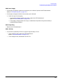
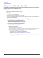
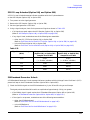
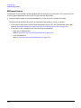
Troubleshooting Assembly Level Problems
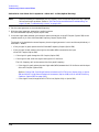
If the Amber Standby LED is Not Working
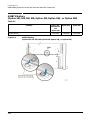
With the power turned off and the signal generator plugged in, the front panel amber standby LED should be
on. The amber Standby LED is controlled by a +15 Vdc standby line supplied by the power supply, which is
routed through the A23 Motherboard to the front panel.
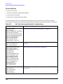
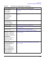
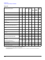
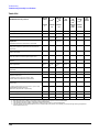
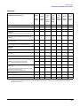
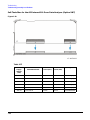
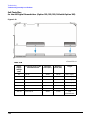
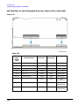
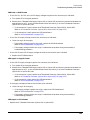
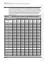
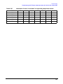
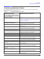
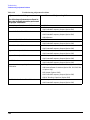
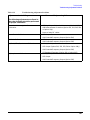
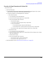
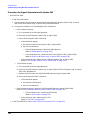
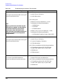
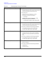
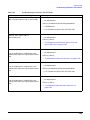
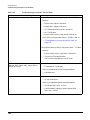
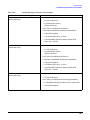
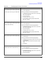
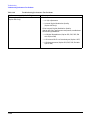
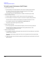
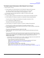
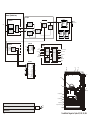
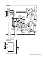
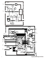
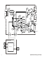
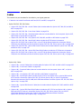
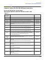
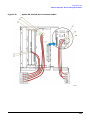
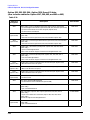
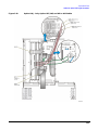
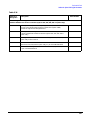
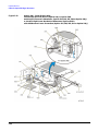
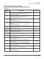
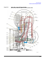
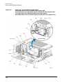
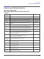
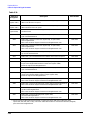
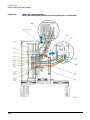
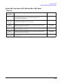
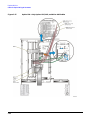
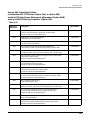
To troubleshoot the +15 Vdc Standby line, turn the signal generator off and follow the signal path. Refer to
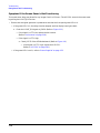
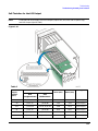
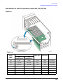
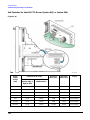
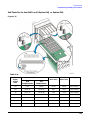
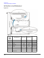
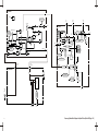
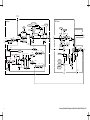
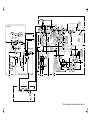
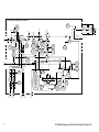
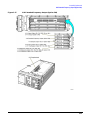
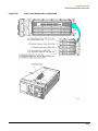
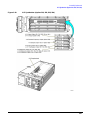
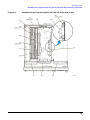
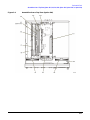
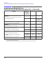
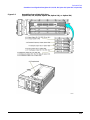
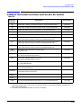
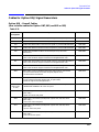
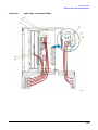
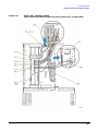
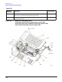
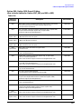
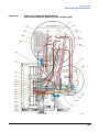
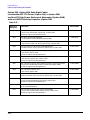
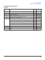
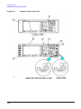
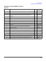
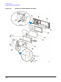
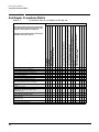
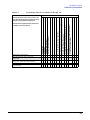
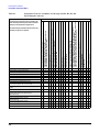
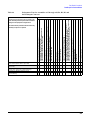
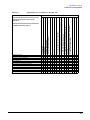
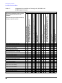
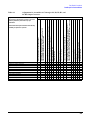
Table 1-12, Table 1-13, Table 1-14, and Table 1-15.
If the Green Line Power LED is Not Working
When the power switch is turned on, the amber LED goes out and the green LED comes on. The fans start
rotating and the front panel display becomes illuminated.
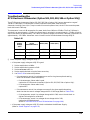
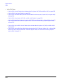
To troubleshoot, refer to Table 1-12, Table 1-13, Table 1-14, and Table 1-15 and verify the power supply
voltages at J28 of the A23 Motherboard. If the supply voltages are correct, replace the A3 Front Panel
Auxilary Board. (Refer to “A3 Front Panel Auxilary Board” on page 2-14.)
If the Fans are Not Working
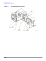
There are three fans located near the front of the instrument that are connected to the A23 Motherboard. The
fan control voltages are supplied by the A6 Power Supply and may be measured at J28 of the A23
Motherboard. The fan control voltage range is +8.5 Vdc (at 23 degrees C) to +12.0 Vdc (at 55 degrees C). At
higher temperatures, the fan voltage increases along with the rotation of the fan.
To troubleshoot, disconnect each fan (one at a time) from the A23 Motherboard and check the fan voltage.
Refer to Table 1-12, Table 1-13, Table 1-14, and Table 1-15. If the fan voltage is correct, replace the fan. (Refer
to “B1 Power Supply Fan” on page 2-71, “B2 Small Fan” on page 2-73, or “B3 Daughterboard/Card Cage Fan”
on page 2-75.)
If the Signal Generator Does Not Power-on and the Power Supply LEDs are Not Working
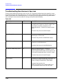
Each of the power supplies has an LED located on the bottom of the A23 Motherboard. If the power supply is
functioning, the green LED is on. Use a voltmeter to measure the supplies on the A23 Motherboard to ensure
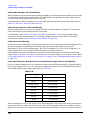
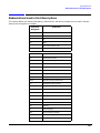
the voltages meet the power supply specifications in Table 1-16.
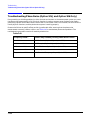
Table 1-16
Power Supply
Acceptable Voltage
+32 Vdc
32.0 ± 0.96 Vdc
+15 Vdc
15.0 ± 0.45 Vdc
+15 Vdc Standby
15.0 ± 0.45 Vdc
+9.0 Vdc
9.0 ± 0.27 Vdc
+5.2 Vdc
5.2 ± 0.16 Vdc
+3.3 Vdc
3.3 ± 0.10 Vdc
−6.0 Vdc
−6.0 ± 0.18 Vdc
−15 Vdc
−15.0 ± 0.45 Vdc
With the exceptions of the +15 Vdc and the +15 Vdc Standby power supply, each power supply should have a
maximum of 10 mVp-p ripple. The +15 Vdc and the +15 Vdc Standby power supply have a maximum ripple
specification of 20 mV p-p. The ripple may be measured using an oscilloscope. If any of the supplies LEDs are
1-28