1
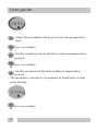
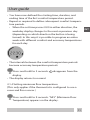
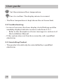
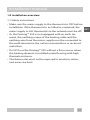
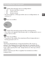
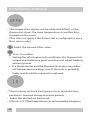
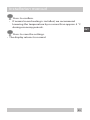
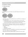
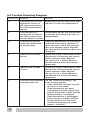
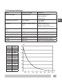
INT Devireg™ 550 Thank you for buying a DEVI product. With this purchase you have obtained a product of the highest quality, designed to give long lasting comfort at a minimum of environmental impact. 2 Contents User Guide 1. Basics.....................................................................................................4 1.1 Safety instructions.....................................................................4 1.2 Functional overview..................................................................5 1.3 Temperature setting ................................................................6 1.4 Changing Battery.......................................................................6 1.5 Operating the child lock..........................................................7 1.6 Switching the thermostat on and off..................................7 2. Advanced.............................................................................................8 2.1 Optional Settings.......................................................................9 2.2 Troubleshooting...................................................................... 12 2.3 Uninstalling Product.............................................................. 12 Installation manual 1.0 Installation overview................................................................ 13 1.1 Safety instructions.................................................................. 13 1.2 Installation guidelines........................................................... 14 2.0 System overview......................................................................... 15 2.1 Three different sensor configurations............................. 15 2.2 Network...................................................................................... 15 2.3 Specifications............................................................................ 16 3.0 Functional overview.................................................................. 17 4.0 Installation - step by step........................................................ 18 4.1 Preparations and guidelines............................................... 18 4.2 Dismantling the thermostat................................................ 18 4.3 Connecting cables.................................................................. 19 4.4 Mounting and reassembling the thermostat............... 20 4.5 Activating the thermostat.................................................... 21 4.6 Configuring basic settings................................................... 21 5.0 Optional settings........................................................................ 26 5.1 Network setup.......................................................................... 26 6.0 Trouble-Shooting Diagram..................................................... 28 7.0 Factory Settings.......................................................................... 29 8.0 Warranty......................................................................................... 30 3 INT User guide 1.0 Basics •The Devireg™ 550 thermostat controls electrical floor heating elements using a built-in and/or external temperature sensor. •The Devireg™ 550’s adaptive function automatically optimises the unit for the room within a few days after installation and continuously collects updated room data. This means improved performance (with compensation for e.g. sudden temperature drops in the room) and precise timing so the selected temperature is achieved at exactly the right time. •The unit can be operated with or without the built-in timer. When the timer is used, the unit can automatically switch between the set comfort temperature and economy temperature at specific times of day. To use the timer, you must first set the day and time and then set the timer. 1.1 Safety instructions • Do not cover the thermostat, e.g. by hanging towels or similar items in front of it! This will impair the unit’s ability to sense and adjust the room temperature correctly. • This does not apply if the thermostat is configured to use a floor sensor only. • Do not spill liquids of any kind into the thermostat. • Do not open, disassemble, or tamper with the thermostat in any way. • If the thermostat is installed in a place frequented by small children, use the child lock. 4 User guide 1.2 Functional Overview Timer on Child lock on Frost protection on Temperature below set value Display Hour display Clock setting active Degree symbol Weekday display Timer setting active Button The thermostat is operated by using the button as follows: Turning clockwise or counter-clockwise to raise or lower values, e.g. when setting the temperature Pressing briefly to activate or deactivate the timer or confirm a setting during configuration Pressing and holding for a number of seconds to access various settings 5 INT User guide 1.3 Temperature Setting Operation without timer: • The hour display appears as an unbroken ring with a blinking dot indicating the current time (if set). Raise or lower the temperature. • The set temperature appears on the display. • The system maintains the set temperature 24 hours a day. • If the thermostat uses a floor sensor only, the display shows the set temperature on a scale from 1 to 10. • If you lower the temperature to +5 °C, appears on the display. • The thermostat maintains a temperature of +5 °C in the room for frost protection. • If you lower the temperature below +5 °C, the thermostat switches off. • “OFF” appears on the display. 1.4 Changing Battery • The backup battery saves clock settings when the mains supply is off. • The battery recharges automatically when the mains supply is on and does not normally need to be changed. 6 User guide 1.5 Operating the child lock Press and hold the button. INT While holding, turn steadily counter-clockwise, until “COdE” appears on the display. Turn clockwise to select “0033”. Press to confirm. or appears on the display. • The child lock is on. The thermostat cannot be operated using the button except to switch off the child lock. • The child lock can be switched off using the same procedure as for switching it on. 1.6 Switching the thermostat on and off The thermostat can only be switched off if the timer is off. The thermostat is on by default. If you lower the temperature below +5 °C, the thermostat switches off. Turn vigorously counter-clockwise to achieve this. “OFF” appears on the display. If you raise the temperature to +5 °C or above, the thermostat switches on again. 7 User guide 2.0 Advanced 2.0.1 Switching the timer on and off The timer is switched on and off by pressing the button. When the timer is on: • appears on the display. • The hour display shows the set comfort temperature periods for the current day as black segments of dots. • The current day is shown on the weekday display. • The system automatically switches between comfort and economy temperatures at the preset times of day. • The economy temperature never appears on the alphanumeric display. The display consistently shows the set comfort temperature, even during economy temperature periods. When the timer is off: • The hour display appears as an unbroken ring with a blinking dot indicating the current time (if set). • The system maintains the set temperature 24 hours a day. Note: • The thermostat can only be switched off if the timer is off. 8 User guide 2.1 Optional Settings 2.1.1 Setting the time and weekday INT Press and hold for 3 seconds. appears on the display. Set the correct time. • A small dot on the hour display shows the currently set time. • When the set time passes 0:00 in either direction, the weekday display changes to the next or previous day (depending on which direction the button is being turned). Press to confirm. disappears from the display. 2.1.2 Setting the timer Press and hold for 6 seconds. appears on the display. • You can now program when the system should switch from comfort temperature to economy temperature and vice versa. 9 User guide Select the weekday where you want the program to start. Press to confirm. Set the starting time of the first comfort temperature period. Press to confirm. Set the duration of the first comfort temperature period. • The duration is shown as a segment of black dots on the hour display. Press to confirm. 10 User guide • You have now defined the starting time, duration, and ending time of the first comfort temperature period. • Repeat as required to define subsequent comfort temperature periods. • When the set time passes 0:00 in either direction, the weekday display changes to the next or previous day (depending on which direction the button is being turned). In this way it is possible to program an entire week with different comfort and economy temperatures for each day. • The intervals between the comfort temperature periods become economy temperature periods. Press and hold for 3 seconds. display. • The display returns to normal. disappears from the 2.1.4 Setting minimum floor temperature (This only applies if the thermostat is configured to use a room and floor sensor.) Press and hold for 9 seconds. “MFt” (Minimum Floor Temperature) appears on the display. 11 INT User guide Set the minimum floor temperature. Press to confirm. The display returns to normal. • The floor temperature is kept above the set lower limit. 2.2 Troubleshooting • In case of an error, the hour display starts flashing and the weekday display indicates an error code from 2 to 7. • Refer to the description of error messages in section 6 of the Installation Manual. • If the system does not function correctly, call a qualified electrician. 2.3 Uninstalling Product • The product should only be uninstalled by a qualified electrician. 12 Installation manual 1.0 Installation overview 1.1 Safety instructions • Make sure the mains supply to the thermostat is OFF before installation. If the thermostat is installed in a network, the INT mains supply to ALL thermostats in the network must be off! • As the Devireg™ 550 is not equipped with an earth terminal, the earthing screen of the heating cable and the earthing wire from the mains supply must be connected to the earth terminal in the surface mounted box or recessed metal box. • Do NOT use the Devireg™ 550 without a floor sensor when the heating element is installed under flooring with high thermal resistance. • The thermostat must not be exposed to moisture, water, and excessive heat. 13 Installation manual 1.2 Installation guidelines • Dismantle the thermostat before installation and observe the following guidelines: Place the Devireg 550™ at a suitable height on the wall. In wet rooms, the thermostat should be installed on an even surface according to local building regulations. Place the thermostat at least 50 cm from windows/ doors that will be left open occasionally. Do not place the thermostat on a wall where it will be exposed to direct sunlight. Do not place the thermostat on the inner side of a wall facing the outside. • Connect all cables to the terminals. • Switch on the mains supply. • Activate and configure the thermostat. 14 Installation manual 2.0 System overview 2.1 Three different sensor configurations FS: Floor sensor (comfort heating) • Suitable for floor heating in e.g. bathrooms. The built-in room sensor is not used. • Comfort heating should be used only to supplement a regular room heating system. INT RS: Room sensor (total heating) • Suitable for control of room temperature in e.g. living rooms. Unsuitable for wet rooms. • The thermostat must be mounted in the same room as the heating elements. RFS: Room and floor sensor (total heating) • Suitable for control of room and floor temperature in e.g. living rooms. Unsuitable for wet rooms. • The floor sensor monitors the floor temperature, limiting heating element temperature to avoid risk of fire and to protect flooring from excessive temperatures. • The maximum floor temperature must be set (see section 4.6 below). It is also possible to set the minimum floor temperature (see section 2.1.4 of the User guide). • The thermostat must be mounted in the same room as the floor sensor and heating elements. 2.2 Network • Up to 32 thermostats can be linked in a network. See section 5.1. 15 Installation manual 2.3 Specifications Temperature range: +5 to +35 °C or OFF Floor temperature limit: +20 to +50 °C Operation voltage: 180-250 VAC, 50/60 Hz Resistive load: 230 V ~ 16A /3680W Inductive load: cos φ 0,3 = Max. 1A Power consumption: < 500 mW Battery back-up: 100 hours Economy set-back: 0 to -30 °C Offset: -5.5 to +5.5 °C IP class: IP30 Sensing unit NTC 15 kOhm AT 25 °C 16 Installation manual 3.0 Functional overview Release tab Frame Mounting screws Front cover Display Button The thermostat is programmed by pressing and holding the button as follows: Seconds held Function accessed 3 Time and weekday setting 6 Timer setting 9 Minimum floor temperature setting 12 Notes Only when configured to use room and floor sensor Basic settings 17 INT Installation manual 4.0 Installation - step by step 4.1 Preparations and guidelines • All necessary cables should be routed to the intended installation point. • The thermostat is designed for installation in a surface mounted box or recessed box with the correct dimensions. • Read and observe the guidelines set forth in section 1.1 and 1.2. 4.2 Dismantling the thermostat Release tab • Push down the release tab. • Carefully detach the front cover. Screws • Remove the two screws. 18 Installation manual • Carefully detach the display module. The module must be pulled straight out to avoid damaging the 8-pin connector plug on the back of the module! Frame INT • Carefully detach the frame. 4.3 Connecting cables • Connect the cables as shown below. Devireg™ 550 NTC sensor Mains supply 180-250 V 50/60 Hz Heating element Max. load 16 Amp. Network connection Devireg™ 550 ONLY 19 Installation manual • Connect wires in heating element and mains supply cables correctly! • Important! Connect the heating cable screen and the mains supply earthing wire to the mounting box earthing terminal. 4.4 Mounting and reassembling the thermostat Screw holes • Mount the base plate on the wall. • Make sure the base plate cannot be moved. • Install the frame, display module, and front cover in the reverse order of disassembly. 20 Installation manual • Install the display module carefully! • Do NOT over-tighten the mounting screws on the display module. 4.5 Activating the thermostat • Switch on the mains supply. • The unit switches on automatically. • If the unit has never been activated before, configure basic settings as described in section 4.6. 4.6 Configuring basic settings • You can access and configure basic settings at any time by pressing and holding the button for 12 seconds, entering code 0044 and changing the parameters as required. • If the button is not operated for approximately 60 seconds, the thermostat automatically exits without storing any changed values. Turn clockwise to select “0044”. Press to confirm. 21 INT Installation manual Select network status of the thermostat: • MAS Master • SLA Slave • ALO Independent (or network not used) • See descriptions of the possible network configurations in section 5.1. • If a network is not used, choose ALO. Press to confirm. • The adaptive function of the Devireg™ 550 can be switched off. Select status for adaptive function: • A dAP Adaptive function on • OFF Adaptive function off Press to confirm. 22 Installation manual Select the desired sensor configuration: • rFS Room and floor sensor • FS Floor sensor • RS Room sensor • See descriptions of the possible sensor configurations in section 2.1. Press to confirm. Select the desired maximum floor temperature. • (This does not apply if the thermostat is configured to use a room sensor only.) Press to confirm. • To protect the cables, the maximum floor temperature is factory preset to 35 °C. Notice: The floor temperature is measured where the sensor is placed. The temperature of the bottom of a wooden floor can be up to 10 degrees higher than the top. Floor manufactures often specify the max. temperature on the top surface of the floor. Please contact your floor supplier for maximum surface temperature. 23 INT Installation manual • The temperature display can be calibrated (offset) so the thermostat shows the same temperature as another thermometer in the room. • (This does not apply if the thermostat is configured to use a floor sensor only.) Select the desired offset value. Press to confirm. • S etting the offset value only recalibrates the thermostat’s temperature reference point and does not adjust heating element power. • If a thermometer and the thermostat display very different temperature readings, one of the units is probably faulty and should be repaired or replaced. • The economy set-back level governs how much the temperature is lowered during economy periods. • Select the desired set-back level. • (Choose -5 °C if the temperature is to be lowered by 5 degrees). 24 Installation manual Press to confirm. • If normal room heating is installed, we recommend lowering the temperature by no more than approx. 5 °C during economy periods. Press to save the settings. • The display returns to normal. 25 INT Installation manual 5.0 Optional settings 5.1 Network setup Each network must contain one (and only one) master unit (MAS). • All other units must be either slave units (SLA) or independent units (ALO). • Independent units in the network will not respond to or send information to a master unit. However, they still count towards the network maximum of 32 units. • The following settings on all slave units are controlled from the master unit. All other settings must be configured on each thermostat. • Time • Weekday • Economy set-back • Network cables are unshielded, untwisted, and unpolarised two-wire cables for easy installation. • Maximum network cable length is 100 m (0.75 mm2 wire 26 Installation manual cross section) or 500 m (1.5 mm2 wire cross section). • The thermostat network can be controlled remotely using e.g. WEB•HOME™ or Devicom™ PC Pro. Further information on how to connect and use these products can be found in the respective user guides. 27 INT 6.0 Trouble-Shooting Diagram Error code Problem Solution 2 The thermostat is configured as master in the local network but has detected another master Reconfigure one of the master thermostats as slave or independent. 3 The thermostat is Reconfigure one of the thermostats configured as slave in as master, or configure all units as the local network but independent. cannot detect a master 4 The thermostat was switched off because of overheating Allow the thermostat to cool down, and then access basic settings to reset the error. Check the wiring if this error appears again. Replace the thermostat if the error does not disappear 5 Short circuit in floor sensor Check the sensor connection to the thermostat. Disconnect the sensor cables and test them. Replace the sensor if it is faulty. Replace the thermostat if the error keeps appearing 6 Open circuit in floor sensor Check the sensor connection to the thermostat. Disconnect the sensor cables and test them. Replace the sensor if it is faulty. Replace the thermostat if the error keeps appearing 7 The clock and weekday Set the clock and weekday. This have not been set error usually appears: • If the clock has not been set and the timer is activated • If the thermostat has been unplugged from the supply voltage for more than 4 days and the backup battery is depleted • If the thermostat is unplugged from the power supply, and the backup battery has not accumulated enough power (takes approx. 16 hours) 28 7.0 Factory Settings Item Factory setting Options Network type Alone (ALO) Independent (ALO) Master (MAS) Slave (SLA) Adaptive function On (AdAP) On (AdAP) Off (OFF) Sensor Room + floor sensor (FS) Floor sensor (FS) Room sensor (RS) Room + floor sensor (FS) Max. floor temperature +35 °C +20 to +50 °C Offset 0 °C -5.5 to +5.5 °C Economy set-back -5 °C -1 to -30 °C Weekday 1 1 to 7 Time Not set Normal 24 hour clock Timer Not set Up to 336 settings/week INT k °C -15 -10 .5 0 5 10 15 20 25 30 35 40 45 50 55 kΩ 84 66 52 41 33 27 22 18 15 12 10 8,6 7,2 6,1 5,2 140 120 100 80 60 40 20 ºC 0 -10º 0º 10º 20º 30º 40º 50º 60º 29 The 2 Year DEVI Warranty: You have purchased a Devireg™ 550 thermostat, which forms an integrated part of a Deviheat™ system, which we are certain will improve your home comfort and economy. Deviheat™ provides complete heating solutions with Deviflex™ heating cables or Devimat™ heating mats, Devireg™ thermostats and Devifast™ fitting bands. If, however, contrary to all expectations, a problem should occur with your heating system, we at DEVI, with manufacturing units in Denmark, are, as European Union suppliers, subject to general product liability rules, as stated in Directive 85/374/CEE, and all relevant national laws which implies that: DEVI provides a warranty for Deviflex™ heating cables and Devimat™ heating mats for a 10 year period and all other DEVI products for a 2 year period against defects in material and production. The guarantee is granted on the condition that the WARRANTY CERTIFICATE on the overleaf is filled out properly in accordance to instructions and that the defect is inspected by, or presented to, DEVI or authorised DEVI distributor. Please note that the wording of the WARRANTY CERTIFICATE must be provided in English or local language with the ISO code for your country in the upper left corner of the front page of the installation instructions in order to release the warranty. The obligation of DEVI will be to repair or supply a new unit, free of charge to the customer, without secondary charges linked to repairing the unit. In case of defective Devireg™ thermostats, DEVI reserves the right to repair the unit free of charge and without unreasonable delay to the customer. The DEVI warranty does not cover installations made by unauthorised electricians, or faults caused by incorrect designs supplied by others, misuse, damage caused by others, or incorrect installation or any subsequent damage that may occur. If DEVI is required to inspect or repair any defects caused by any of the above, then all work will be fully chargeable. The DEVI warranty is void, if payment of the equipment is in default. At all times, we at DEVI will respond honestly, efficiently and promptly to all queries and reasonable requests from our customers. The above mentioned warranty concerns product liability whereas matters in relation to legislation on sale of goods shall be referred to national law. 30 2 YEAR WARRANTY Warranty Certificate The DEVITM Guarantee is granted to: Name: Address: City: INT Country: Telephone: Attention: The Warranty Certificate must be completed correctly for the Warranty to be valid. Please read the Warranty conditions on the previous page. Type of thermostat: Material number: Electrical installation by: Date: Suppliers Stamp Date / - 31 Article No.: 08095121 DEVI A/S Tel: +45 7488 8500 Fax: +45 7488 8501 www.devi.com United Kingdom and Ireland Danfoss Randall Ltd. Tel: 0845 121 7400 Fax: 0845 121 7515 www.danfoss-randall.co.uk Australia DEVI Heating Systems Ltd. Tel: 02 9997 2811 Fax: 02 9997 7852 www.devi.com.au New Zealand DEVI Heating Systems Ltd. Tel: 33 48 00 70 Fax: 33 48 00 67 www.devi.co.nz VICKJ402 International 11/2009 Version - 05.02