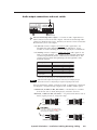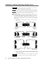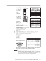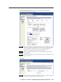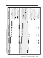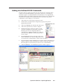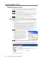
1
System 5 IP Series
System Switchers with Integrated A/V Switching, Audio Amplification,
and Projector Control
68-611-01 Rev. D
05 06
Precautions
Safety Instructions • English
Warning
This symbol is intended to alert the user of important operating and maintenance
(servicing) instructions in the literature provided with the equipment.
Power sources • This equipment should be operated only from the power source indicated on the product. This
equipment is intended to be used with a main power system with a grounded (neutral) conductor. The
third (grounding) pin is a safety feature, do not attempt to bypass or disable it.
This symbol is intended to alert the user of the presence of uninsulated dangerous
voltage within the product’s enclosure that may present a risk of electric shock.
Power disconnection • To remove power from the equipment safely, remove all power cords from the rear of
the equipment, or the desktop power module (if detachable), or from the power source receptacle (wall
plug).
Caution
Read Instructions • Read and understand all safety and operating instructions before using the equipment.
Retain Instructions • The safety instructions should be kept for future reference.
Follow Warnings • Follow all warnings and instructions marked on the equipment or in the user
information.
Avoid Attachments • Do not use tools or attachments that are not recommended by the equipment
manufacturer because they may be hazardous.
Consignes de Sécurité • Français
Power cord protection • Power cords should be routed so that they are not likely to be stepped on or pinched by
items placed upon or against them.
Servicing • Refer all servicing to qualified service personnel. There are no user-serviceable parts inside. To
prevent the risk of shock, do not attempt to service this equipment yourself because opening or removing
covers may expose you to dangerous voltage or other hazards.
Slots and openings • If the equipment has slots or holes in the enclosure, these are provided to prevent
overheating of sensitive components inside. These openings must never be blocked by other objects.
Lithium battery • There is a danger of explosion if battery is incorrectly replaced. Replace it only with the
same or equivalent type recommended by the manufacturer. Dispose of used batteries according to the
manufacturer’s instructions.
Avertissement
Ce symbole sert à avertir l’utilisateur que la documentation fournie avec le matériel
contient des instructions importantes concernant l’exploitation et la maintenance
(réparation).
Alimentations• Ne faire fonctionner ce matériel qu’avec la source d’alimentation indiquée sur l’appareil. Ce
matériel doit être utilisé avec une alimentation principale comportant un fil de terre (neutre). Le troisième
contact (de mise à la terre) constitue un dispositif de sécurité : n’essayez pas de la contourner ni de la
désactiver.
Ce symbole sert à avertir l’utilisateur de la présence dans le boîtier de l’appareil
de tensions dangereuses non isolées posant des risques d’électrocution.
Déconnexion de l’alimentation• Pour mettre le matériel hors tension sans danger, déconnectez tous les cordons
d’alimentation de l’arrière de l’appareil ou du module d’alimentation de bureau (s’il est amovible) ou
encore de la prise secteur.
Attention
Lire les instructions• Prendre connaissance de toutes les consignes de sécurité et d’exploitation avant
d’utiliser le matériel.
Conserver les instructions• Ranger les consignes de sécurité afin de pouvoir les consulter à l’avenir.
Respecter les avertissements • Observer tous les avertissements et consignes marqués sur le matériel ou
présentés dans la documentation utilisateur.
Eviter les pièces de fixation • Ne pas utiliser de pièces de fixation ni d’outils non recommandés par le
fabricant du matériel car cela risquerait de poser certains dangers.
Protection du cordon d’alimentation • Acheminer les cordons d’alimentation de manière à ce que personne ne
risque de marcher dessus et à ce qu’ils ne soient pas écrasés ou pincés par des objets.
Réparation-maintenance • Faire exécuter toutes les interventions de réparation-maintenance par un technicien
qualifié. Aucun des éléments internes ne peut être réparé par l’utilisateur. Afin d’éviter tout danger
d’électrocution, l’utilisateur ne doit pas essayer de procéder lui-même à ces opérations car l’ouverture ou le
retrait des couvercles risquent de l’exposer à de hautes tensions et autres dangers.
Fentes et orifices • Si le boîtier de l’appareil comporte des fentes ou des orifices, ceux-ci servent à empêcher
les composants internes sensibles de surchauffer. Ces ouvertures ne doivent jamais être bloquées par des
objets.
Lithium Batterie • Il a danger d’explosion s’ll y a remplacment incorrect de la batterie. Remplacer uniquement
avec une batterie du meme type ou d’un ype equivalent recommande par le constructeur. Mettre au reut les
batteries usagees conformement aux instructions du fabricant.
Sicherheitsanleitungen • Deutsch
Vorsicht
Dieses Symbol soll dem Benutzer in der im Lieferumfang enthaltenen
Dokumentation besonders wichtige Hinweise zur Bedienung und Wartung
(Instandhaltung) geben.
Stromquellen • Dieses Gerät sollte nur über die auf dem Produkt angegebene Stromquelle betrieben werden.
Dieses Gerät wurde für eine Verwendung mit einer Hauptstromleitung mit einem geerdeten (neutralen)
Leiter konzipiert. Der dritte Kontakt ist für einen Erdanschluß, und stellt eine Sicherheitsfunktion dar. Diese
sollte nicht umgangen oder außer Betrieb gesetzt werden.
Dieses Symbol soll den Benutzer darauf aufmerksam machen, daß im Inneren des
Gehäuses dieses Produktes gefährliche Spannungen, die nicht isoliert sind und
die einen elektrischen Schock verursachen können, herrschen.
Stromunterbrechung • Um das Gerät auf sichere Weise vom Netz zu trennen, sollten Sie alle Netzkabel
aus der Rückseite des Gerätes, aus der externen Stomversorgung (falls dies möglich ist) oder aus der
Wandsteckdose ziehen.
Achtung
Lesen der Anleitungen • Bevor Sie das Gerät zum ersten Mal verwenden, sollten Sie alle Sicherheits-und
Bedienungsanleitungen genau durchlesen und verstehen.
Aufbewahren der Anleitungen • Die Hinweise zur elektrischen Sicherheit des Produktes sollten Sie
aufbewahren, damit Sie im Bedarfsfall darauf zurückgreifen können.
Befolgen der Warnhinweise • Befolgen Sie alle Warnhinweise und Anleitungen auf dem Gerät oder in der
Benutzerdokumentation.
Keine Zusatzgeräte • Verwenden Sie keine Werkzeuge oder Zusatzgeräte, die nicht ausdrücklich vom
Hersteller empfohlen wurden, da diese eine Gefahrenquelle darstellen können.
Instrucciones de seguridad • Español
Schutz des Netzkabels • Netzkabel sollten stets so verlegt werden, daß sie nicht im Weg liegen und niemand
darauf treten kann oder Objekte darauf- oder unmittelbar dagegengestellt werden können.
Wartung • Alle Wartungsmaßnahmen sollten nur von qualifiziertem Servicepersonal durchgeführt werden.
Die internen Komponenten des Gerätes sind wartungsfrei. Zur Vermeidung eines elektrischen Schocks
versuchen Sie in keinem Fall, dieses Gerät selbst öffnen, da beim Entfernen der Abdeckungen die Gefahr
eines elektrischen Schlags und/oder andere Gefahren bestehen.
Schlitze und Öffnungen • Wenn das Gerät Schlitze oder Löcher im Gehäuse aufweist, dienen diese zur
Vermeidung einer Überhitzung der empfindlichen Teile im Inneren. Diese Öffnungen dürfen niemals von
anderen Objekten blockiert werden.
Litium-Batterie • Explosionsgefahr, falls die Batterie nicht richtig ersetzt wird. Ersetzen Sie verbrauchte
Batterien nur durch den gleichen oder einen vergleichbaren Batterietyp, der auch vom Hersteller
empfohlen wird. Entsorgen Sie verbrauchte Batterien bitte gemäß den Herstelleranweisungen.
Advertencia
Este símbolo se utiliza para advertir al usuario sobre instrucciones importantes
de operación y mantenimiento (o cambio de partes) que se desean destacar en el
contenido de la documentación suministrada con los equipos.
Alimentación eléctrica • Este equipo debe conectarse únicamente a la fuente/tipo de alimentación eléctrica
indicada en el mismo. La alimentación eléctrica de este equipo debe provenir de un sistema de distribución
general con conductor neutro a tierra. La tercera pata (puesta a tierra) es una medida de seguridad, no
puentearia ni eliminaria.
Este símbolo se utiliza para advertir al usuario sobre la presencia de elementos con
voltaje peligroso sin protección aislante, que puedan encontrarse dentro de la caja
o alojamiento del producto, y que puedan representar riesgo de electrocución.
Desconexión de alimentación eléctrica • Para desconectar con seguridad la acometida de alimentación eléctrica
al equipo, desenchufar todos los cables de alimentación en el panel trasero del equipo, o desenchufar el
módulo de alimentación (si fuera independiente), o desenchufar el cable del receptáculo de la pared.
Precaucion
Leer las instrucciones • Leer y analizar todas las instrucciones de operación y seguridad, antes de usar el
equipo.
Conservar las instrucciones • Conservar las instrucciones de seguridad para futura consulta.
Obedecer las advertencias • Todas las advertencias e instrucciones marcadas en el equipo o en la
documentación del usuario, deben ser obedecidas.
Evitar el uso de accesorios • No usar herramientas o accesorios que no sean especificamente recomendados
por el fabricante, ya que podrian implicar riesgos.
安全须知 • 中文
这个符号提示用户该设备用户手册中有重要的操作和维护说明。
这个符号警告用户该设备机壳内有暴露的危险电压,有触电危险。
注意
阅读说明书 • 用户使用该设备前必须阅读并理解所有安全和使用说明。
保存说明书 • 用户应保存安全说明书以备将来使用。
遵守警告 • 用户应遵守产品和用户指南上的所有安全和操作说明。
避免追加 • 不要使用该产品厂商没有推荐的工具或追加设备,以避免危险。
Protección del cables de alimentación • Los cables de alimentación eléctrica se deben instalar en lugares donde
no sean pisados ni apretados por objetos que se puedan apoyar sobre ellos.
Reparaciones/mantenimiento • Solicitar siempre los servicios técnicos de personal calificado. En el interior no
hay partes a las que el usuario deba acceder. Para evitar riesgo de electrocución, no intentar personalmente
la reparación/mantenimiento de este equipo, ya que al abrir o extraer las tapas puede quedar expuesto a
voltajes peligrosos u otros riesgos.
Ranuras y aberturas • Si el equipo posee ranuras o orificios en su caja/alojamiento, es para evitar el
sobrecalientamiento de componentes internos sensibles. Estas aberturas nunca se deben obstruir con otros
objetos.
Batería de litio • Existe riesgo de explosión si esta batería se coloca en la posición incorrecta. Cambiar esta
batería únicamente con el mismo tipo (o su equivalente) recomendado por el fabricante. Desachar las
baterías usadas siguiendo las instrucciones del fabricante.
警告
电源 • 该设备只能使用产品上标明的电源。 设备必须使用有地线的供电系统供电。 第三条线
(地线)是安全设施,不能不用或跳过 。
拔掉电源 • 为安全地从设备拔掉电源,请拔掉所有设备后或桌面电源的电源线,或任何接到市
电系统的电源线。
电源线保护 • 妥善布线, 避免被踩踏,或重物挤压。
维护 • 所有维修必须由认证的维修人员进行。 设备内部没有用户可以更换的零件。为避免出
现触电危险不要自己试图打开设备盖子维修该设备。
通风孔 • 有些设备机壳上有通风槽或孔,它们是用来防止机内敏感元件过热。 不要用任何东
西挡住通风孔。
锂电池 • 不正确的更换电池会有爆炸的危险。必须使用与厂家推荐的相同或相近型号的电池。
按照生产厂的建议处理废弃电池。
Table of Contents
Chapter 1 • Introduction ...................................................................................................... 1-1
About the System 5 IP Series Switchers .............................................................. 1-2
Video and audio features ................................................................................................ 1-2
Video .................................................................................................................................... 1-2
Audio .................................................................................................................................... 1-2
Control features ................................................................................................................ 1-2
Controlling the switcher ...................................................................................................... 1-2
Controlling other devices .................................................................................................... 1-3
How the System 5 IP Works: System 5 IP Components
and Interactions ................................................................................................................. 1-4
Chapter 2 • Installation: Labeling, Mounting, Cabling ................................... 2-1
UL/Safety Requirements ................................................................................................. 2-2
Mounting the System 5 IP ............................................................................................ 2-3
Rack mounting .................................................................................................................. 2-3
Rear Panels and Cabling ................................................................................................ 2-4
Power, A/V input, and video output connections ........................................................ 2-4
Audio output connections and reset switch .................................................................. 2-5
Resetting the unit ............................................................................................................... 2-8
Control connections ......................................................................................................... 2-9
Front Panel Cabling ........................................................................................................ 2-14
Chapter 3 • Front Panel Features and Basic Operation .................................. 3-1
Front Panel Features ........................................................................................................ 3-2
Buttons ............................................................................................................................... 3-3
Adjustment features and input 5 .................................................................................... 3-4
Optimizing the Audio ..................................................................................................... 3-5
Configuring the Preamp output level ............................................................................ 3-6
Adjusting audio input levels ........................................................................................... 3-6
Making adjustments ......................................................................................................... 3-6
Front Panel Security Lockout (Executive Modes) ............................................ 3-7
LCD Menus and Basic Switcher Setup ................................................................... 3-8
Chapter 4 • Software- and Web Page-based Setup and Control ............. 4-1
Configuring the Hardware ........................................................................................... 4-2
Setting up the PC for IP communication ....................................................................... 4-3
Setting up the System 5 IP switcher (at initial startup) for IP communication ......... 4-5
Configuring the switcher using the ARP command ........................................................... 4-5
Configuring the switcher via a Web browser .................................................................... 4-6
Configuring the switcher via the Global Configurator software ...................................... 4-7
System 5 IP Switchers • Table of Contents
i
PRELIMINARY
Installing or Replacing Button Labels ................................................................... 2-2
Table of Contents, cont’d
Global Configurator Software for Windows® ................................................... 4-7
IR Learner™ Software for Creating Customized IR Driver Files ............... 4-7
Embedded Web Pages ..................................................................................................... 4-8
Status .................................................................................................................................. 4-9
System Status ...................................................................................................................... 4-9
Statistics ............................................................................................................................... 4-9
Configuration .................................................................................................................. 4-10
File Management ............................................................................................................ 4-13
File types: a key to file names .......................................................................................... 4-13
Files that can be stored on the switcher and on the PC .................................................. 4-13
Files stored on the PC only and used to generate files for the switcher ........................ 4-14
File Management buttons and when to use them .......................................................... 4-14
Control ............................................................................................................................. 4-15
Controlling the System 5 IP via GlobalViewer™ Web Pages .................... 4-18
PRELIMINARY
Control ............................................................................................................................. 4-18
Monitor ............................................................................................................................ 4-19
Schedule .......................................................................................................................... 4-19
Info ................................................................................................................................... 4-20
Chapter 5 • SIS™ Programming and Control ........................................................... 5-1
Host-to-switcher communications ............................................................................... 5-2
Switcher-initiated messages ............................................................................................ 5-2
Password information ...................................................................................................... 5-3
Error responses .................................................................................................................. 5-3
Error response references ................................................................................................. 5-3
Commands and Reponses ................................................................................................... 5-4
Using the command/response tables .............................................................................. 5-4
Symbol definitions ........................................................................................................... 5-5
Command/response table for SIS commands ..................................................................... 5-8
Command/response table for special function SIS commands ........................................ 5-32
Button/switch memory block numbering ................................................................... 5-36
Chapter 6 • Special Applications ..................................................................................... 6-1
Working With Combination Source Devices ...................................................... 6-2
Alternative connections from a DVD-VCR player to the switcher .............................. 6-2
Using separate source output ports ................................................................................... 6-2
Using a distribution amplifier ............................................................................................. 6-2
Using IRCM control modules for DVD-VCR control ...................................................... 6-3
Using an IRCM-DV+ control module for DVD-VCR control .......................................... 6-3
Adding User-Defined RS-232 Commands .............................................................. 6-9
Routing Audio to an External Amplifier and a Volume Controller .... 6-10
Slaving an MPS 112 Switcher to a System 5 IP ............................................... 6-11
Connecting the System 5 IP and MPS 112 .................................................................... 6-11
Configuring the System 5 for switcher slaving ........................................................... 6-12
ii
System 5 IP Switchers • Table of Contents
Appendix A • Reference Material .................................................................................. A-1
Specifications ..................................................................................................................... A-2
Part Numbers and Accessories ................................................................................. A-6
Included parts .................................................................................................................. A-6
Accessories ........................................................................................................................ A-6
Cables ................................................................................................................................ A-7
Audio Block Diagram ...................................................................................................... A-8
Glossary ................................................................................................................................. A-9
Appendix B • Firmware Updates ..................................................................................... B-1
Determining the Firmware Version ........................................................................ B-2
Updating the Main Firmware ...................................................................................... B-4
Updating firmware via the System 5 IP’s embedded Web page ................................. B-4
Updating FPGA Firmware .............................................................................................. B-5
Determining the FPGA version ........................................................................................ B-5
Replacing the FPGA chip .................................................................................................. B-5
All trademarks mentioned in this manual are the properties of their respective owners.
68-611-01 Rev. D
05 06
System 5 IP Switchers • Table of Contents
iii
PRELIMINARY
Using the LCD display at power-on ................................................................................ B-2
Using the Global Configurator software ........................................................................ B-2
Using a Web browser ....................................................................................................... B-2
PRELIMINARY
Table of Contents, cont’d
iv
System 5 IP Switchers • Table of Contents
System 5 IP Switchers
1
Chapter One
Introduction
About the System 5 IP Series Switchers
How the System 5 IP Works: System 5 IP Components and Interactions
Introduction
About the System 5 IP Series Switchers
The Extron System 5 IP switchers are five input, one output, active, audio/video
(A/V) switchers capable of controlling a projector and various other items such as
lights, a projector lift, or a screen motor. Throughout this manual they are referred
to as the System 5 IP, the switcher, or System 5.
Four models are available:
• the FPC models, which include front panel controls for projector power,
selectable functions/room control, input selection, volume adjustment, and
simple configuration
N
N
with an audio amplifier (amplifier model)
without an audio amplifier (nonamplifier model)
• the non-FPC models, which have no front panel controls except an input 5
selection button
N
N
with an audio amplifier (amplifier model)
without an audio amplifier (nonamplifier model)
PRELIMINARY
Video and audio features
Video
The System 5 IP accepts a variety of video formats (RGB, S-video, or composite
video); inputs one and two are configurable. Video output can be RGB, S-video, or
composite video.
Audio
Audio input can be balanced or unbalanced. The System 5 IP provides fixed
(Lineout) and variable (Preamp) line level audio outputs for use with an external
amplifier, self-powered speakers, or assistive listening devices. The fixed (Lineout)
audio output provides an audio signal that is unchanged by the switcher’s volume
control, which is useful when the switcher is connected to mixing or recording
equipment. The variable (Preamp) audio output enables audio levels to be adjusted
by the switcher’s volume control. In addition, the amplifier model switchers
include an integrated 40-watt (rms) (20 watts per channel into a 4 or 8 ohm load)
audio amplifier for connection to non-powered speakers.
Control features
Controlling the switcher
All models of the System 5 IP can can be controlled via a control system or host
computer using RS-232 communication and/or via IP Link™ Ethernet control. The
FPC model also offers front panel controls. The optional IR 402 remote control and
optional SCP hard-wired control pads can be used with any model, and they mimic
the switcher’s front panel controls for regular user mode functions (for control
rather than setup).
RS-232 and IP control
Input switching and control of the System 5 IP can be accomplished by simple
ASCII commands (Simple Instruction Set, SIS™) or via the Extron Global
Configurator software, which offers more setup options than SIS programming
does.
Additional control features available via IP only
The switchers include embedded Web pages (accessible via Ethernet/IP), which
include online diagnostics and monitoring of the basic switcher control features.
1-2
System 5 IP Switchers • Introduction
As an integrated part of the System 5 IP switchers, IP Link provides these
advantages:
Global compatibility — The switcher uses standard Ethernet communication
protocols, including ARP, DHCP, ICMP (ping), TCP/IP, Telnet, HTTP, and
SMTP.
Embedded Web page serving — IP Link™ products such as the System 5 IP offer
7.25 MB of flash memory for storing Web pages, configuration settings, and
device drivers. Data in flash memory is served at a transfer rate of 6 Mbits
per second.
Multi-user support — Two hundred (200) simultaneous connections enable each
IP Link device to support many concurrent users and improve system
throughput by sending information in parallel.
E-mail notification — The System 5 IP can be set up to send an e-mail when the
projector has been disconnected or the projector’s lamp has been used for a
designated number of hours.
Controlling other devices
The System 5 IP offers two methods of projector and source device control: RS-232
or infrared (IR). The switcher can learn IR signals from remote controls to
communicate with sources such as VCRs and DVD players. Users can create their
own device drivers (IR or RS-232) or go to the Extron Web site to obtain device
drivers.
Tx
L
TRO
CON
& VCR
DVD
DVD
R
TUNE
VCR
U
TOR
JEC
PRO
R
Extron
SCP 150 AAP
ECTO
R PROJOFF
MEN
NEXT
PLAY
/REW
TS
LIGH
ON
T
T
AAP
150
SCP
LIGH
OFF
INPU
5
INPU
4
T
INPU
3
INPU
2
T
E
PAUS
/FWD
TITLE
PREV
PC
TS
T
STOP
R
ENTE
TION
FUNC ON
BUTT
ECTO
PROJON
UME
VOL
INPU
1
Extron
IRCM-DV+
AL
SIGN
Control Pad
IR
LINK
Extron
IR Link
Extron IR 402
Remote Control
RS-232 Control
Laptop
R
2
-23
RS
IG/
_
NF
CO
T
_
+
LEF
T
NE
ER
ETH
HT
C
A
P
SC
/IR/2
E
CM
T
OU1
4/9
IAL
ER 3/8
B
A
IR/S
2/7
RS-
S
Tx
Rx
G
IN
Ps
G
+V
S
G
IN
G
+V
1/6
NT
CO
OJ
PR 232
Y
G
S
S
G
IN
G
D
C
IR
IN
SCP
C
2
1
C
CM
B
3
4
C
5
6
AMPLIFIED
OUT
+
RIG
S
LAY
RE
MP
EA
PR
UT
EO
LIN
4
DIO
AU
3
4 ohm Speakers
or
8 ohm Speakers
DIO
AU
2
DIO
AU
1
DIO
AU
B
G
INPUT 4
INPUT 3
VID
V
H
OUTPUT
R
VID
C
VID
V
H
Y/C
B/C
Y/C
C
G/Y
V
Y
ID
R/V
0V
Extron
System 5 IP
TCP/IP
Network
B/C
INPUT 2
-24
100
H
INPUT 1
1.3A
G/Y
ID
R/V
z
60H
50-
System Switcher
Document
Camera
DVD
VCR
Screen
Control
INPU
T
BUF
MONFER
ITORED LOC
OUT
ID PIN 4
ID PIN 11
AL
PUT
H.
SHIF
T
VGA
INTE
RFA RGB
109
CE
xi
W
/ADS
P
Extron
RGB 109xi
Interface
PC
Projector
A typical application for a System 5 IP switcher with integrated audio
amplifier
System 5 IP Switchers • Introduction
1-3
PRELIMINARY
Management ability via Global Configurator and GlobalViewer™ — The free
management software allows you to control, monitor, and schedule various
functions of products connected to IP Link products such as the System 5 IP.
Introduction, cont’d
How the System 5 IP Works:
System 5 IP Components and Interactions
Unlike previous models of Extron system switchers or the Extron MediaLink
Controller (MLC 206), the System 5 IP requires and uses event files to perform all
functions except basic input switching and volume control. The event files define,
monitor, and govern how the System 5 IP works. Below is an example of how the
System 5 IP interacts with its accessories, event scripts, drivers, ports, and input
and output devices.
System 5 IP
PC
with
Global
Config.
or
Web
Browser
FPC’s
Lights
LAN
Port
Host
Port
Memory
PRELIMINARY
FPC
Syst. 5 IP
Firmware
MAIN EVENT
(0.evt)
Proj. Driver
(5.evt)
Serial
Driver
RS-232
Proj Port
2-way
RS-232
Proj.
DVD
Driver
(1.evt)
Serial
Driver
IR/Serial
Port A
1-way
RS-232
DVD
VCR Driver
(7.eir)
IR
Driver
IR/Serial
Port B
IR
Out
VCR
SCP
SCP’s
Lights
CMs
IR 402
The System 5 can be configured completely via the Windows-based Global
Configurator software. Once you have set up how you want the switcher to work
(set up audio, assigned drivers to ports, configured buttons and relays, and set up
IP addresses and functions), that information is saved to a configuration file which
is uploaded into the switcher.
The configuration information is used to create the “main event” (0.evt) script file
that defines the switcher’s operation. The main event file also controls and
monitors ports, optional SCP control panels, and changes made at the switcher’s
front panel.
Each button on the switcher and on any connected SCPs, control modules (IRCMs,
ACMs, RCMs), or the IR 402 remote control has two switch numbers assigned to it:
one for the button press, one for release. Scripts are compiled to generate the main
event file to monitor any button press or release and to generate the actions (issuing
commands, triggering relays, switching inputs) associated with the buttons.
1-4
System 5 IP Switchers • Introduction
System 5 IP Switchers
2
Chapter Two
Installation: Labeling, Mounting,
Cabling
UL/Safety Requirements
Installing or Replacing Button Labels
Mounting the System 5 IP
Rear Panels and Cabling
Front Panel Cabling
Installation: Labeling, Mounting, Cabling
UL/Safety Requirements
The Underwriters Laboratories (UL) requirements listed below pertain to the safe
installation and operation of a System 5 IP Switcher.
1.
Do not use the switcher near water or expose it to liquids.
To reduce the risk of fire or electric shock, do not expose this apparatus
to rain or moisture.
2.
Clean the switcher only with a dry cloth.
3.
Do not install the switcher near any heat source, such as a radiator, heat
register, stove, or another apparatus (including amplifiers) that produces
heat.
4.
Unplug the switcher during lightning and thunder storms or when it will
be unused for long periods.
Installing or Replacing Button Labels
PRELIMINARY
For the System 5 IP with front panel buttons or an optional SCP control panel,
you may wish to customize the button labels. The labels can
be changed at any time, but it is more convenient to change
them before you rack mount the switcher. Follow these steps
to change the translucent button labels:
1.
Remove the button assembly from the switcher.
The button assembly consistes of a clear lens
cap, the label, and a white diffuser. See the
exploded view diagram below.
Pry the button
from the base.
Insert a small, flat bladed screwdriver, such as
an Extron Tweeker, to gently pry a button
assembly off from button plunger, as shown at
right.
2.
Locate the small, corner notch on the lens cap and slide the screwdriver
between the lens cap and the diffuser. See A in the picture below.
3.
Using a rotating motion of the screwdriver
(see B at right), carefully pry the two
pieces apart.
4.
Select a button label from the
printed label sheets
included with the
switcher. Remove
the label from its
Clear Lens
backing, if
applicable, and
insert the button
label into the
button cap.
Plunger
Base
TE
XT
Diffuser
B
Pry the two
pieces apart.
A
Notch
Separating the two-
2-2
5.
piece button here at
Press the lens cap
the corner.
and diffuser back
together, and reverse steps
2 and 1 to reinstall the button
in the switcher’s front panel.
6.
Repeat steps 1 to 5 as needed to relabel other buttons.
System 5 IP Switchers • Installation: Labeling, Mounting, Cabling
Button Label
Mounting the System 5 IP
Rack mount the switcher, if desired, using the included rack mounting kit
(part #70-077-03), which is factory installed. Otherwise, affix the four rubber feet
(included) to the corners of the bottom of the switcher for use on a tabletop.
Rack mounting
For rack mounting, do not install the rubber feet. The rack mounting brackets are
attached to the switcher at the factory. Fasten the switcher to the rack using the
supplied machine screws.
The System 5 IP switchers do not contain cooling fans. Make sure there
will be adequate air circulation around the unit once it is installed. To
provide adequate air circulation and prevent overheating, Extron
recommends allowing one rack unit of space (1.75"/4.5 cm) above and
below the switcher.
EM
PRELIMINARY
CAUTION
5 IP
ST
SY
T5
PU
IN
E
VO
M
LU
AU
DI
PC
VIDE
O
O
P
CLI
L
MA
NOR
NAL
SIG
AD
JU
ST
TEM R
SWSITCHE
SW
XT
NE
NU
TIO
ME
N
EC
EL
OP
PT
TS
LA
PU
D
IN
DV
R
VC
TR
RO
Y
A
PL
DIS
Y
LA
DISP ER
W
PO
Y
LA
DISPTE
MU
OM
OM
ROLAY
RE1
OL
N
CO
OM
ROLAY
RE2
PC
1
DE
SK
TO
P
5/
B
RG
4
3
2
1
OM
ROLAY
RE3
IG
NF
CO
IR
Rack mounting the System 5 IP switcher
System 5 IP Switchers • Installation: Labeling, Mounting, Cabling
2-3
Installation: Labeling, Mounting, Cabling, cont’d
Rear Panels and Cabling
Power, A/V input, and video output connections
H
V
INPUT 2
C
R/VID
G/Y
VID
VID
H
B/C
V
R
Y/C
G
B
H
Y/C
V
VID
IR/SERIAL OUT
PROJ CONT
Y
C
C
B
A
RS-232
AUDIO
B/C
Y
OUTPUT
G/Y
INPUT 4
R/VID
INPUT 3
1.3A
INPUT 1
100-240V
Tx Rx G Ps G +V
S G S G S G
L
2
1
R
L
R
L
3
CM/IR/SCP
D
A B C D E
S G
+V G CM IR SCP
R
L
4
R
50-60Hz
PRELIMINARY
1
2
3
5
4
1
Power connector — After you have completed the audio/video and control
connections, connect a standard IEC power cord from the AC power supply
to this connector.
2
Inputs 1 and 2: RGBHV/S-video/composite video inputs — Connect cables
from an RGBHV, S-video (Y/C), or composite video source to each of these
inputs. See the diagrams below.
RGBHV
Inputs must be configured for either
R/VID
G/Y
B/C
H
V
video or RGB. See chapters three,
Y
C
four, and five for details.
Composite Video
S-video
R/VID
G/Y
B/C
H
R/VID
V
G/Y
B/C
H
V
3
Inputs 3 and 4: S-video/composite video inputs — Connect the cable from
either an S-video (Y/C) source (using the 4-pin mini DIN connector) or a
composite video (Vid) source (using the BNC connector) to each of these
inputs. Inputs 3 and 4 are not configurable.
4
Audio inputs — These inputs correspond to the like-numbered video
inputs. For each input, connect the cable from a balanced or unbalanced
stereo or mono audio input source. See the wiring diagrams below.
R
R
Tip
Sleeve
L
Tip
Ring
Sleeve (s)
Tip
Ring
L
Tip
Sleeve
Unbalanced Stereo Input
Balanced Stereo Input
(high impedance)
(high impedance)
R
R
Tip
Sleeve
L
Tip
Ring
Sleeve (s)
Tip
Ring
L
Tip
Sleeve
The length of exposed wires is critical.
The ideal length is 0.2" (5 mm).
• If the stripped section of wire is
longer than 0.2", the exposed
wires may touch, causing a
short circuit between them.
• If the stripped section of wire is
shorter than 0.2", wires can be
easily pulled out even if tightly
fastened by the captive screws.
Unbalanced Mono Input
Balanced Mono Input
(high impedance)
(high impedance)
0.2” (5 mm) max.
Do not tin the wires!
After the audio inputs and outputs are connected, see pages 3-5 through 3-7,
and pages 3-9, 4-11, and 5-9 for instructions on how to adjust the per-input
audio levels.
Display outputs — Cable these output BNC connectors to an RGBHV,
S-video (Y/C), or composite video
R
G
B
Y
port on the projector or display. See
Y = luma
the diagram at left.
OUTPUT
5
C = chroma
H
V
RGBHV
2-4
VID
C
Composite S-video
Video
System 5 IP Switchers • Installation: Labeling, Mounting, Cabling
Audio output connections and reset switch
3
LAN
RELAYS
A
B
C
C 1
2 C 3
4 C 5
CONFIG/RS-232
R
1
_
LEFT
_
4/8 ohm
AMPLIFIED
OUT
RIGHT
+
L PREAMP R
+
L LINEOUT R
6
2 (Amplifier
Models Only)
Lineout and Preamp audio outputs — Connect an audio output device to
either connector for line level audio outputs. The Lineout and Preamp audio
outputs are simultaneously active. Therefore, two devices can be connected at
the same time (one to each output).
• The Lineout connector outputs a fixed level audio signal that is not
_
_
affected by the audio adjustments listed in the table below. A tape
recorder or assistive listening device would typically be connected here.
• The Preamp connector outputs a variable, line level audio signal for use
with a powered amplifier. The volume can be controlled (attenuated)
via the front panel knob, RS-232, or Ethernet/IP communication. The
volume range is 0 (mute) through 40 steps (0% through 100% of the
maximum volume).
Setting/Adjustment
Bass/Treble
Volume
Mono/Stereo
Balance
-10 dBV/+4 dBu
Gain/Attenuation
(per-input)
Lineout*
Preamp
Amplifier
—
—
—
—
—
—
* Lineout is not affected by any of the adjustments listed above.
After the audio inputs and outputs are connected, see chapter four for
instructions on how to adjust the per-input and preamp audio levels.
Lineout and Preamp outputs can both be wired as unbalanced or balanced
(see diagram). Only the Preamp output has the -10 dBV/+4 dBu options.
• Unbalanced, -10 dBV (-8 dBu, 320 mVrms) — the default, for consumer
level devices such as VCRs, DVD players, and stereo receivers
• Balanced, +4 dBu (+6 dBV, 1.23 Vrms) — for professional devices such as
mixers, signal processors, and power amps
R
Right
Unbalanced Stereo Output
Tip
Ring
Sleeve(s)
Tip
Ring
Left
R
Left
L
L
Tip
NO GROUND HERE.
Sleeve(s)
Tip
NO GROUND HERE.
Right
Balanced Stereo Output
CAUTION
For unbalanced audio, connect the sleeve(s)
to the center contact ground. DO NOT connect
the sleeve(s) to the negative (-) contacts.
R
Right
Unbalanced Mono Output
Tip
Ring
Sleeve
Left
R
Left
L
L
Tip
NO GROUND HERE.
Sleeve
Right
Balanced Mono Output
System 5 IP Switchers • Installation: Labeling, Mounting, Cabling
2-5
PRELIMINARY
1
Installation: Labeling, Mounting, Cabling, cont’d
CAUTION
Connect the sleeve to ground. Connecting the sleeve to a negative (-)
terminal will damage the audio output circuits.
Mono output is selected via RS-232 or the front panel. If mono output is
selected, a mono audio signal is output on both channels (left and right).
If an output connector is wired for balanced output, the level will be 6 dB
higher than if the connector is wired for unbalanced output.
2
Amplified output (for models with an integrated audio amplifier only) —
The switcher’s internal, 40-watt (20 watts per channel into a 4 or 8 ohm
load) audio amplifier outputs stereo (default) or dual mono signals on a
four-position screw terminal connected to nonpowered speakers. Cable
speakers to this screw terminal for a 20 watts (rms) per channel amplified
audio output.
1.
Use the appropriate wiring for the load as shown in the following
illustrations.
Mono or
Stereo +
Mono or
Stereo +
LEFT
_
4/8 ohm
AMPLIFIED
OUT
PRELIMINARY
4 Ohm Load
or
8 Ohm Load
_
+
+
RIGHT
Mono or
Stereo –
Mono or
Stereo –
Mono or
Stereo +
Mono or
Stereo +
4 Ohm Total Load
LEFT
_
4/8 ohm
AMPLIFIED
OUT
8
ohms
_
+
+
RIGHT
8
ohms
8
ohms
Mono or
Stereo –
Mono or
Stereo –
Mono or
Stereo +
Mono or
Stereo +
4
ohms
4 Ohm Total Load
4/8 ohm
LEFT
_
4
ohms
4
ohms
Mono or
Stereo –
Mono or
Stereo –
8 Ohm Total Load
2.
2-6
8
ohms
4
ohms
+
+
_
RIGHT
AMPLIFIED
OUT
4 Ohm Load
or
8 Ohm Load
8 Ohm Total Load
Using the front panel, RS-232, or IP control, set the switcher for either
mono or stereo audio output. That setting affects the amplified output
and the Preamp output.
CAUTION
Do not short the terminals to ground or the amplifier will be damaged.
CAUTION
Do not bridge the outputs. Bridging could damage the amplifier.
System 5 IP Switchers • Installation: Labeling, Mounting, Cabling
This connector outputs either stereo (left and right) or dual mono channels.
The two mono output audio channels are identical.
If you intend to connect just one speaker, you should set the amplifier to
output a mono signal.
The amplifier’s power supply is separate from the switcher’s main power
supply. If the amplifier shuts off (if the volume gain is set too high, for
example), connected SCPs and control modules will also shut off, but the rest
of the switcher will continue to function normally, allowing you to lower the
gain or volume so the amplifier’s power will be restored.
If only one speaker will be used, connect it to one of the output channels
and configure the output for mono.
When the power amp output is configured for
• no limit (SIS command 0*56#), output is about 20 watts
• -10 dB attenuation (10*56#), output is about 2 watts
Normally two 4 or 8 ohm speakers should be connected to the switcher, and
the switcher should be set for stereo output in order to get 20 watts out per
channel. If you wire either the left or right side (not both) and set the
switcher for stereo output, the result is more than 20 watts output because
the connected channel will draw power from the other channel. This might
damage the speaker, and the signal will be distorted before maximum
volume is reached. For mono output the power amplifier is capable of
reaching 40 watts. If you intend to connect just one speaker, you should set
the amplifier to output mono audio.
If input gain or volume is too high, the amplifier’s power limiting circuit
will limit the power so that the amplifier does not output more than
20 watts. Continuing to increase the gain or volume will eventually cause
the amplifier’s power supply to shut off, which will also cause the SCP and
control modules to power off because they receive their power from the
amp’s power supply. If you lower the volume and input gain, the switcher
will resume functioning.
To reinitialize the switcher, perform an audio or system reset after setting the
power amplifier limit. The switcher must experience a volume change for
the amplifier’s power limit to be functional.
3
Reset button and LED — Pressing this recessed button causes various IP
functions and Ethernet connection settings to
Reset
R
Reset
be reset to the factory defaults. See “Resetting
Button
LED
the unit” for details.
(Recessed)
System 5 IP Switchers • Installation: Labeling, Mounting, Cabling
2-7
PRELIMINARY
Power amp limits (for models with an integrated amplifier)
Via SIS commands or the switcher’s embedded Web pages, the power amp
sensitivity can be adjusted to limit how much actual power is delivered to
the speakers. This feature is useful in environments such as classrooms
where you want to control how loud the room’s audio gets in order to avoid
disturbing adjacent rooms.
Installation: Labeling, Mounting, Cabling, cont’d
Resetting the unit
There are four reset modes (numbered 1, 3, 4, and 5 for the sake of comparison
with an Extron IPL product) that are available by pressing the Reset button on
the rear panel. The Reset button is recessed, so use a pointed stylus, ballpoint
pen, or Extron Tweeker to access it. See the following table for a summary of the
modes.
CAUTION
Review the reset modes carefully. Using the wrong reset mode may
result in unintended loss of flash memory programming, port
reassignment, or switcher reboot.
The reset modes listed below close all open IP and Telnet connections and
close all sockets. Also, the following modes are separate functions, not a
continuation from mode 1 to mode 5.
Reset Mode Comparison/Summary
PRELIMINARY
Mode Activation
2-8
Result
Purpose/Notes
1
Hold down the
recessed Reset button
while applying power
to the switcher.
System 5 IP reverts to the factory default
firmware. Event scripting will not start if
the switcher is powered on in this mode.
All user files and settings (drivers, audio
adjustments, IP settings, etc.) are
maintained.
Use mode 1 to
remove a version of
firmware if
incompatibility
issues arise.
3
Hold down the Reset
button for about 3 sec.
until the Reset LED
blinks once, then press
Reset momentarily (<1
sec.) within 1 second.
Mode 3 turns events on or off. During
resetting, the Reset LED flashes 2 times if
events are starting, 3 times if events are
stopping.
Events must be
turned on if you
want to change IP
settings or
scheduling.
4
Hold down the Reset
button for about 6 sec.
until the Reset LED has
blinked twice (once at
3 sec., once at 6 sec.).
Then press Reset
momentarily (for
<1 sec.) within 1
second.
Mode 4
• Enables ARP capability.
• Sets the IP address back to factory default.
• Sets the subnet back to factory default.
• Sets the default gateway address back to
the factory default.
• Sets port mapping back to factory default.
• Turns DHCP off.
• Turns events off.
Reset LED flashes 4 times in quick
succession during reset.
Mode 4 enables you
to set IP address
information using
ARP and the MAC
address.
5
Hold down the Reset
button for about 9 sec.
until the Reset LED has
blinked three times
(once at 3 sec., once at
6 sec., once at 9 sec.).
Then press Reset
momentarily (for
<1 sec.) within 1
second.
Mode 5 performs a complete reset to
factory defaults (except the firmware).
• Does everything mode 4 does.
• Resets all real time adjustments: all
audio/video settings, limit initial power
up volume, power up/down delay, auto
power down, and misc. options.
• Clears driver-port associations and port
configurations (IR/RS-232).
• Removes button configurations.
• Resets all IP options.
• Removes scheduling settings.
• Removes/clears all files from switcher.
The Reset LED flashes 4 times in quick
succession during the reset.
Mode 5 is useful if
you want to start
over with
configuration and
uploading, and also
to replace events.
System 5 IP Switchers • Installation: Labeling, Mounting, Cabling
_
_
Control connections
3
D
C
B
A
RS-232
L
2
R
L
R
L
3
R
+V G CM IR SCP
L
4
R
B
C
C 1
2 C 3
4 C 5
CONFIG/RS-232
R
L LINEOUT R
6
L PREAMP R
RIGHT
_
LEFT
_
Projector control (Proj Cont) RS-232 port (-5 VDC to +5 VDC) — Connect a
cable between the projector/display and the left three poles of this 3.5 mm
captive screw connector for RS-232 one- or two-way control. Commands
from a downloaded projector/display driver or user-defined command
strings entered via the configuration program can be sent to the display
device from this port.
Connect a cable between the right three poles of the Proj Cont port and
accessories such as an Extron Power Sensor. The Power Sensor can be used
to let the switcher know when the projector is on or off. If these pins are not
connected to a Power Sensor, the SNS and ground pins can be used for digital
input as can pin 1 and ground of the 9-pin D RS-232 Host Control port.
Digital input: the power sense pin and the ground pin together act as a
digital input port (depending on configuration). This allows for an
additional way to trigger events or functions (such as triggering relays,
issuing commands, or sending an e-mail).
When configured as a digital input, this port will be in one of two states:
1 (on, high) or 2 (off, low). A closed circuit = a logic 1, an open circuit = a
logic 0. Threshold voltages are <0.6 VDC = low, >0.70 VDC = high.
Use the following illustrations as a wiring guide. Wiring varies depending
on the projector or display model. In most cases only the transmit (Tx) and
ground connections will be needed for projector control.
System 5 IP
For bidirectional RS-232 communication, the transmit,
Rear Panel
ground, and receive pins must be wired at both the
PROJ CONT
switcher and the projector/display.
RS-232
Each projector or display may require different
wiring. For details, refer to the manual
that came with the projector/display.
Projector
Tx Rx G Ps G +V
Bidirectional
Panel
Ground ( )
Receive (Rx)
Transmit (Tx)
Ground ( )
Receive (Rx)
Transmit (Tx)
Maximum distances from the System 5 IP to the device being controlled may
vary up to 200 feet (61 m). Factors such as cable gauge, baud rates, environment, and output levels (from the switcher and the device being controlled)
all affect transmission distance. Distances of about
System 5 IP
50 feet (15 m) are typically not a problem. In some
Rear Panel
cases the System 5 IP may be capable of transmitPROJ CONT
ting and controlling a given device via RS-232 up
to 250 feet (76 m) away, but the RS-232 response
Tx Rx G Ps G +V
levels of that device may be too low for the
System 5 IP to
Tip (+12V)
detect.
RS-232
Ring
(signal)
To a
projector
or display
Transmit (Tx)
Receive (Rx)
Ground ( )
+12VDC
Ground ( )
Power
sense
To an Extron
Power Sensor
(60-271-01)
Sleeve ( )
3.5 mm Stereo Plug
System 5 IP Switchers • Installation: Labeling, Mounting, Cabling
2-9
PRELIMINARY
1
1
LAN
A
+
S G S G S G S G
A B C D E
6
+
Tx Rx G Ps G +V
5
RELAYS
CM/IR/SCP
2
IR/SERIAL OUT
PROJ CONT
4
4/8 ohm
2
AMPLIFIED
OUT
1
Installation: Labeling, Mounting, Cabling, cont’d
2
IR/Serial Output ports — Depending on how the switcher is configured via
the configuration software, these ports output either infrared signals or
unidirectional RS-232 signals for controlling various devices such as VCRs
and DVD players. Before it can be used for controlling a device, each port
must be set up via the configuration software for either IR or RS-232
communication and associated with a device driver.
For RS-232 output (-5 VDC to +5 VDC), use the illustration below as a
wiring guide, then plug a serial cable into this captive screw connector.
RS-232 default protocol:
• RS-232
• 9600 baud
• no parity
• 8 data bits
• 1 stop bit
• pacing = 0 ms
IR/SERIAL OUT
B
A
D
C
50'
PRELIMINARY
S G S G S G
S G
2-pole Captive Screw
Connectors
(15.2 m)
(See note.)
G = Ground
S = Signal (Tx)
To a
Controllable
Device
Maximum distances from the System 5 IP to the device being controlled may
vary up to 200 feet (61 m). Factors such as cable gauge, baud rates,
environment, and output levels (from the switcher and the device being
controlled) all affect transmission distance. Distances of about 50 feet (15 m)
are typically not a problem. In some cases the System 5 IP may be capable of
transmitting and controlling a given device via RS-232 up to 250 feet (76 m)
away.
For infrared (IR) output (0 to +5 VDC), wire an IR Emitter (2 emitters,
maximum, per port) as shown in the following picture for a modulated or
demodulated signal and ground. For specific information about wiring
more than one IR Emitter per port, refer to the Extron IR Emitter Installation
Guide, part #68-808-01. Alternatively, an Extron IR Broadcaster can be
connected here if you need to send out IR signals to a wider area than is
possible for an IR Emitter. The IR Broadcaster requires a +12 VDC power
connection. The +V and ground pins of the Projector Control port can be
used to provide this power.
IR/SERIAL OUT
A
B
C
S G S G S G
D
S G
100'
(30.5 m)
G = Ground
S = Signal (IR)
White Striped Wire
IR Emitter 1
See chapter four for details on how to set up these ports for IR or RS-232
control.
2-10
System 5 IP Switchers • Installation: Labeling, Mounting, Cabling
CM/IR/SCP port — You can connect up to four Extron control modules
(IRCMs, ACMs, RCMs), one Extron IR Link infrared signal repeater, and/or
up to two Extron SCP control pads to this port to allow remote control of the
System 5 IP switcher or other items. A maximum of seven devices can be
connected to this port. Use the following diagram as a wiring guide.
The SCP replicates most of the switcher’s front panel controls. The
SCP and the IR Link can receive IR signals from an optional IR 402 remote
control and send them to the switcher. Control modules can be used (once
the switcher is set up) to control VCRs, DVD players, tape decks, a projector
lift, or screen control. Refer to the appropriate device’s user’s manual.
The control modules, IR Link, and SCPs can be daisy chained, as shown in
the following diagram. Extron CTL (Comm-Link) cable is recommended for
these connections.
System 5 IP
Rear Panel
CM/IR/SCP
A B C D E
200' (61 m) max.
+V G CM IR SCP
SCP 150
DISPLAY
VOLUME
DISPLAY
ON
E SCP communication
C IRCM, ACM, RCM
B Ground ( )
A +12 VDC
DISPLAY
OFF
DOC
CAM
VCR
FUNCTION
BUTTON
AUTO
IMAGE
PIC
MUTE
IR
PC
PRELIMINARY
3
DVD
Maximum =
2 SCPs
Per System
LAPTOP
SCP 150
C IRCM/ACM/RCM
B Ground ( )
A +12 VDC
DVD & VCR CONTROL
Maximum =
4 Control Modules
(4 Module Addresses)
CTL or CTLP Cable Color Code:
E
D
C
B
A
SCP communication
Modulated IR (for IR Link)
Control Module communication
Ground ( ) & drain wire
+12 VDC
= White
= Violet
= Black and Drain
= Red
Control modules
include IRCM, ACM,
RCM, and CM models.
DVD
Tx
VCR
TITLE
MENU
ENTER
TV/VCR
TUNER
PREV/REW PLAY NEXT/FWD PAUSE
STOP
IRCM-DV+
The maximum total distance between the System 5 IP and a connected device
is 200' (61 m).
Extron recommends that you connect the cable’s drain wire to the ground
pin at both ends. This reduces EMI interference.
This port provides up to 12 VDC for powering the SCP control pads or
other devices. The automatic current protection circuit for this port limits
the draw to 0.5 amperes.
Devices other than the optional accessories mentioned above can be powered
from this port as long as the maximum current rating (0.5 amperes) is not
exceeded.
If the audio amplifier’s power supply shuts off, the power to this port is also
shut down.
System 5 IP Switchers • Installation: Labeling, Mounting, Cabling
2-11
Installation: Labeling, Mounting, Cabling, cont’d
4
Relay ports (24 V, 1 A) — These six relays allow control of items such as
room lighting, window coverings, and display screens. These contacts may
be used to control any equipment as long as the contact specifications of a
total of 24 volts at 1 ampere are not exceeded for each port. The pin
assignments are shown in the picture below.
Group A
Group B
RELAYS
Common
Group C
RELAYS
A
B
C
C 1
2 C 3
4 C 5
6
Relay 2
Relay 1
RELAYS
A
B
C
C 1
2 C 3
4 C 5
Common
6
A
B
C
C 1
2 C 3
4 C 5
Relay 4
Relay 3
Common
6
Relay 6
Relay 5
These relays are normally open by default. They can be configured via SIS
commands or the configuration software to operate as follows:
• on—relay closes and stays closed until otherwise instructed
• off—relay opens and stays open until otherwise instructed
PRELIMINARY
• toggle—relay changes from open to closed or from closed to open until
otherwise instructed
Toggle on
Normally
Open (1)
Common
Off (Open)
or
Common
Toggle off
All relays
are
normally
open.
Normally
Open (2)
Relay Toggle
Relay Off
Off (Open)
Turn off after
a set period
Common
On (Closed)
Turn
on
Common
Off (Open)
Common
Off (Open)
Common
Common
Relay On
On (Closed)
Common
On (Closed)
Common
• pulse—momentary (timed) (press to turn on, timeout to turn off)
Relay Pulse
A
B
C
C 1
2 C 3
4 C 5
6
You can also use SIS commands or the configuration
software to specify pulse duration.
Via the Global Configurator software, each relay can
be associated with a front panel button (projector
on/off buttons, function buttons, or input selection
buttons) or can be operated independently.
5
Common
Relay 1
Relay 2
LAN connector and LEDs — An Ethernet connection can be used on an
ongoing basis to connect and to control the System 5 IP (and the devices
connected to it) in an Ethernet network.
Plug a cable into this RJ-45 socket, and connect the other end of the cable to
a network switch, hub, router, or PC connected to an Ethernet LAN or the
Internet.
• For 10Base-T (10 Mbps) networks, use a Cat 3 or better cable.
• For 100 Base-T (max. 155 Mbps) networks, use a Cat 5 cable.
You will also need to configure this port before using it.
2-12
LAN
Activity LED — This yellow LED blinks to indicate
network activity.
RJ-45
Port
Link LED — This green LED lights to indicate a good
network connection.
Link
LED
System 5 IP Switchers • Installation: Labeling, Mounting, Cabling
Activity LED
• Use a
crossover
cable for
connection
directly to a
PC. Wire the
connector as
shown in the
tables.
Clip Down
12345678
RJ-45
connector
Straight-through Cable
(for connection to a switch, hub, or router)
End 1
Pin
1
2
3
4
5
6
7
8
12345678
Wire Color
white-orange
orange
white-green
blue
white-blue
green
white-brown
brown
Twisted
Pairs
End 2
Pin
1
2
3
4
5
6
7
8
Wire Color
white-orange
orange
white-green
blue
white-blue
green
white-brown
brown
Crossover Cable
(for direct connection to a PC)
End 1
Pin
1
2
3
4
5
6
7
8
Configure the
1&2 3&6 4&5 7&8
settings for this
port via either SIS
commands or the Global
Configurator program. See chapters
four and five for details.
Wire Color
white-orange
orange
white-green
blue
white-blue
green
white-brown
brown
End 2
Pin
1
2
3
4
5
6
7
8
Wire Color
white-green
green
white-orange
blue
white-blue
orange
white-brown
brown
LAN port defaults:
• switcher’s IP address: 192.168.254.254
• gateway’s IP address: 0.0.0.0
• subnet mask: 255.255.0.0
• DHCP: off
6
Configuration/RS-232 port — For switcher configuration and control,
connect a Windows-based PC or an RS-232 control system to the
System 5 IP via this female, 9-pin HD connector.
RS-232 protocol:
• 38400 baud
• 1 stop bit
• no parity
• 8 data bits
• no flow control
The pin assignments of this
connector are as follows:
5
1
9
6
DB9 Pin Locations
Female
Pin RS-232 function
1
2
3
4
5
6
7
8
9
–
Tx
Rx
–
Gnd
–
–
–
–
Description
No connection
Transmit data
Receive data
No connection
Signal ground
No connection
No connection
No connection
No connection
The front panel 2.5 mm mini stereo connector Config port serves the same
function as this rear panel port but is independent from it.
Both configuration ports require 38400 baud communication. This is a
higher speed than many other Extron products use. The System 5 IP
configuration software automatically sets the connection for the appropriate
speed. If using HyperTerminal or a similar application, make sure the PC or
control system connected to these ports is set for 38400 baud.
System 5 IP Switchers • Installation: Labeling, Mounting, Cabling
2-13
PRELIMINARY
• Use a straightthrough cable
for connection
to a switch,
hub, or router.
Installation: Labeling, Mounting, Cabling, cont’d
Front Panel Cabling
SYSTEM 5 IP
INPUT 5
PC VIDEO
AUDIO
CONFIG
IR
1
1
2
Config port — This 2.5 mm mini stereo jack serves the same function as the
rear panel Configuration/RS-232 port, but it is easier to access than the rear
port after the switcher has been installed in a rack and cabled. The optional
9-pin D to 2.5 mm stereo mini TRS RS-232 cable (part #70-335-01, shown
below) can be used for this connection. This port has the same protocol as
the rear panel port.
PRELIMINARY
RS-232 protocol:
• 38400 baud
• 1 stop bit
• no parity
• 8 data bits
• no flow control
6 feet
(1.8 m)
Part #70-335-01
1
6
9
5
Tip
Ring
Sleeve (Gnd)
9-pin D
Connection
TRS Plug
Pin 2
Pin 3
Pin 5
Computer's RX line
Computer's TX line
Computer's signal ground
Tip
Ring
Sleeve
Both configuration ports require 38400 baud communication. This is a
higher speed than many other Extron products use. The configuration
software (Global Configurator version 2.0 or higher) automatically sets the
connection for the appropriate speed. If using HyperTerminal or a similar
application, make sure the PC or control system connected to these ports is
set for 38400 baud.
Maximum distances from the System 5 IP to the device being controlled may
vary up to 200 feet (61 m). Factors such as cable gauge, baud rates,
environment, and output levels (from the switcher and the device being
controlled) all affect transmission distance. Distances of about 50 feet
(15 m) are typically not a problem. In some cases the System 5 IP may be
capable of transmitting and controlling a given device via RS-232 up to
250 feet (76 m) away, but the RS-232 response levels of that device may be
too low for the System 5 IP to be able to detect.
2-14
System 5 IP Switchers • Installation: Labeling, Mounting, Cabling
Input 5 — This input allows convenient
access for a laptop computer. The
15-pin HD connector accepts RGB
computer video, and the 3.5 mm mini
stereo jack accepts unbalanced stereo
audio input. The audio plug can be wired
as shown at right.
Tip (L)
Ring (R)
Sleeve ( )
3.5 mm Stereo Plug Connector
(unbalanced)
Non-FPC model only:
Press the button to the left of these connectors (shown on page 2-14) to
select input 5 as the active input. Pressing the button again deselects
input 5, and the previously selected input becomes active.
PRELIMINARY
2
System 5 IP Switchers • Installation: Labeling, Mounting, Cabling
2-15
PRELIMINARY
Installation: Labeling, Mounting, Cabling, cont’d
2-16
System 5 IP Switchers • Installation: Labeling, Mounting, Cabling
System 5 IP Switchers
3
Chapter Three
Front Panel Features and
Basic Operation
Front Panel Features
Optimizing the Audio
Front Panel Security Lockout (Executive Modes)
LCD Menus and Basic Switcher Setup
Front Panel Features and Basic Operation
A System 5 IP can be set up and operated by using:
• The front panel controls.
• A computer, a touch screen panel, or any other device that can send and receive
the serial communications through the RS-232 port.
• A computer or other device using an Ethernet connection and IP protocol (Telnet
or a Web browser).
• An Extron SCP control pad.
• The Extron IR 402 remote control or another device that can send IR signals.
Most settings can be adjusted only through a host computer using Extron’s Simple
Instruction Set (SIS) (a set of simple keystroke commands) or the Extron Global
Configurator configuration software for Windows. For details on setup and control
via RS-232 or Ethernet, see chapters four and five.
Front Panel Features
System 5 IP with FPC
PRELIMINARY
DISPLAY
ON
OFF
INPUT SELECTION
AUTO
IMAGE
PIC
MUTE
PC
DOC
CAM
1
2
DVD
VCR
LAPTOP
CONFIG
IR
1
2
3
4
5
3
5/ PC
4
6
System 5 IP without FPC
CONFIG
IR
1
1
2
3
Power LED — When this LED is lit, the switcher is receiving power.
Early models of these switchers may not have this LED.
2
IR receivers — The larger infrared receiver (on the left) accepts IR signals
from the Extron IR 402 infrared
Switcher Control
IR Learning
remote control for controlling the
switcher.
Use the smaller receiver (on the
right) for receiving and “learning”
codes from other devices’ remote
controls. The System 5 IP uses
learned IR signals to control devices
such as VCRs or DVD players. See
chapter four and the Extron
IR Learner™ software for details.
This receiver accepts infrared signals
of from 30 kHz to 62 kHz.
CONFIG
IR
CONFIG
IR
15 15
40
40
2"–12"
(4–30 cm)
30 feet
max.
1
2
System 5IP Switchers • Front Panel Features and Basic Operation
3
4
5
6
7
8
9
0
IR 402
3-2
System
5 IP
3
Config port — This port is a front panel version of the rear panel
Configuration/RS-232 port, and it is independent of the rear panel port. This
port makes it possible to upload and configure device drivers and also to
initiate IR learning via a front panel connection after the switcher has been
installed.
Connect a Windows-based PC or an RS-232 control system to this 2.5 mm
mini stereo-style (tip-ring-sleeve) connector. You can use the Extron 9-pin D
to 2.5 mm stereo mini TRS RS-232 cable (part #70-335-01) or make your own
cable. See page 2-15 for a wiring diagram and port protocol.
This port requires 38400 baud communication, a higher speed than many other
Extron products use. The System 5 IP configuration software automatically
sets the connection for the appropriate speed. If using HyperTerminal or a
similar application, make sure the PC connected to these ports is set for 38400
baud.
11
Input 5 — These connectors (shown on the next page) accept computer-video
and stereo audio input signals. See chapter two for wiring instructions.
The System 5 IP with FPC (front panel control) has backlit buttons, and the nonFPC model has an unlit input 5 selection button only. The functions, events, and
scripts associated with these buttons are available in both models, and they
function the same way. Pressing the corresponding button on the Extron IR 402
remote control or an Extron SCP keypad will cause that button’s functions to be
executed exactly as if you had pressed a front panel button.
Each Projector On/Off, Function/Room, and Input button can be set up to perform
up to six functions, which can be combinations of the following options:
• a driver operation—execute an RS-232 or IR control command that is part of a
device driver (for a projector, VCR, DVD, audio source, etc.)
• a relay operation—turn relays on or off, or toggle or pulse a relay
• an internal operation—change a front panel button’s brightness or color or
execute an SIS command for the switcher
• a user-defined RS-232 operation—issue a non-driver-associated RS-232
command (one that you programmed separately) via a specific port (IR/Serial
Out A, B, C, D; or the projector control port) or an internal command for the
System 5 IP itself.
The Menu and Next buttons are reserved for switcher control and menu functions
only; they are not configurable/programmable.
By default all buttons illuminate brightly when selected (active), and light dimly
when deselected. The button caps are removable so the button labels can be
changed.
4
Projector On/Off buttons — After they have been configured, press the On
button to turn the projector or display device on, and press the Off button to
power it off. Only one of these two buttons can be selected (active) at once.
Via the configuration software, other functions and relays can be associated
with each of these buttons.
If the Projector On or Projector Off button is selected (clicked on) via the
switcher’s default Web page or via the Global Configurator software or the
GlobalViewer Web pages, the buttons on the switcher and/or optional SCP
control pads will not blink and the projector will not turn on/off unless these
buttons have been configured with driver command or function. See chapter
four for information on the configuration software and internal Web pages.
System 5 IP Switchers • Front Panel Features and Basic Operation
3-3
PRELIMINARY
Buttons
PRELIMINARY
Front Panel Features and Basic Operation, cont’d
5
Function/room control buttons — These buttons can be set up to control the
switcher’s relays, and they can also be set up to execute IR or RS-232
commands of your choice. The relays can be used to control items in the
room such as a projector lift, screen motor, or lighting. For details on how the
relays operate and can be configured, see the installation instructions in
chapter two and the configuration software information in chapter four.
Three function buttons are available on the System 5 IP FPC model, but both
models have a virtual fourth function button that can be accessed via
software, an optional SCP, or the embedded Web page.
6
Input selection buttons — Press one of these buttons to select the desired
audio and video input. The button lights brighter and remains lit while an
audio-video input is selected. During audio breakaway (selectable only with
SIS commands via RS-232 or Ethernet control), audio is switched separately
from video; the selected video input’s button lights steadily, and the audio
input’s button blinks. (See page 5-8 under “Input selection” for how to select
A/V breakaway.) As with 4 and 5 , other functions and relays can be
associated with each of these buttons via the Global Configurator software.
7
Menu and Next buttons — See the description and illustration below.
10
Input 5 selection button (non-FPC model only) — Press this button to switch
to input 5. Press this button again to deselect input 5 and return to the
previously selected input.
Adjustment features and input 5
System 5 IP with FPC
SYSTEM 5 IP
VOLUME
INPUT 5
MAX
MENU
PC VIDEO
MID
NEXT
AUDIO
MIN
ADJUST
7
8
9
11
System 5 IP without FPC
SYSTEM 5 IP
INPUT 5
PC VIDEO
AUDIO
10
11
If you adjust volume, gain, bass, or treble, it takes 1 minute 40 seconds
(100 seconds) for data in the switcher’s RAM to be saved to flash memory.
7
Menu and Next buttons — Press these buttons to access and navigate
through the switcher’s LCD menus and options. For details, see “LCD Menus
and Basic Switcher Setup” on page 3-8. These two buttons light only when
they have been pressed, during switcher setup. They are not userprogrammable/configurable. To disable any of the front panel security
lockout modes (executive modes), press the front panel Menu and Next
buttons simultaneously for about three seconds.
Video output may turn off briefly (for the duration of the RGB delay setting)
while you set the video configuration for inputs 1 and 2 or when you press the
Menu and Next buttons and enter the Video Config menu.
3-4
System 5 IP Switchers • Front Panel Features and Basic Operation
8
LCD screen — This screen displays basic system status, menu, and
configuration information. You will use it primarily during switcher
configuration. During regular operation, the LCD displays the volume level.
9
Volume/Adjust knob and Min/Mid/Max LEDs — Rotate this knob to adjust
the volume when the switcher is in regular user mode, and use it to select
options from menus in switcher setup mode. The LEDs indicate different
things depending on the mode (user or setup) the switcher is in. See
appendix A for an audio block diagram.
•
In the user (regular) mode the LEDs function as volume level indicators.
Rotate the Volume knob to adjust the output level of the Preamp and
Amplified outputs. The volume range is 0 to 40 steps, which is
displayed as 0% to 100% in the configuration software.
User (regular) mode
VOLUME
Maximum volume limit (100%) (settings 36–40)
MAX
MID
Minimum threshold (at least 10%)
(volume settings 1–15)
The volume of the Lineout output is not affected by this volume adjustment.
•
In setup mode these LEDs function as input level indicators. Rotate the
Volume knob and observe the LEDs to set up the proper audio input
levels.
p
g ,
g
MAX
MID
Normal: a blinking LED indicates that the level is
set properly for maximum power output.
MIN
Signal: when lit this LED indicates that a signal of
at least -22 dBV (-20 dBu) is detected at the input.
NOTE
If the Max/Clip LED lights, the audio may be clipped.
During setup audio/video breakaway is disabled.
Per-input audio level settings can be adjusted via this front panel knob or via
RS-232/Telnet/Web browser control.
There is an input gain adjustment tolerance of ±2 dB.
Optimizing the Audio
Input and output audio levels may need to be adjusted depending on the variation
of output levels from different source devices. The Preamp default output level is
set for the consumer product level of -10 dBV. The level of the Lineout output
cannot be adjusted: input level = output level.
Bass and treble should be adjusted once the input and output levels have been
adjusted. By default, bass and treble have been set to 0.
Input levels can be adjusted via the front panel (for the FPC model) or the free
Global Configurator software. Other adjustments must be performed via the
software (available at www.extron.com) through one of the switcher’s
Configuration/RS-232 ports or the Ethernet (LAN) port.
CAUTION
Do not connect speakers to the switcher’s amplifier output until setup has
been completed and volume has been set to the minimum level.
System 5 IP Switchers • Front Panel Features and Basic Operation
3-5
PRELIMINARY
ADJUST
50% of the maximum volume (settings 16–35)
MIN
Front Panel Features and Basic Operation, cont’d
Configuring the Preamp output level
Prior to adjusting any input levels, an output level must be selected from the
following options. You will not need to change the output level if the Preamp
output will not be used.
• -10 dBV, unbalanced (consumer) (default): typically used when the switcher’s
output is connected to the unbalanced input of a consumer product such as a
VCR, stereo receiver-amplifier, or self-powered speakers.
• +4 dBu, balanced (professional): typically used when the switcher’s output is
connected to the balanced input of a professional product such as a mixer, power
amplifier, or some assistive listening devices.
Check manufacturers’ specifications for details on input/output devices that
you will connect to the Preamp output.
Adjusting audio input levels
PRELIMINARY
Adjusting the input level for each input via the front panel or the supplied
configuration software ensures that the switcher can deliver maximum power out
of the amplifier, output the proper signal on the Preamp output, and prevent
noticeable jumps in audio levels during input switching.
The input level can be adjusted (-40 dB to +30 dB) for all of the inputs. The default
level is 0 dB.
Common output levels for audio source devices range from -20 dBV, unbalanced to
+4 dBu, balanced. If the input level settings are not closely matched to the source
devices’ levels, the signal may be overdriven and distorted.
• Consumer portable devices such as personal CD players and laptops typically
have fixed and/or variable unbalanced outputs. If connecting a variable level
output to the switcher, you must make adjustments with the source’s volume set
to maximum.
• Consumer nonportable devices such as VCRs, DVD players, and computer
sound cards typically output an unbalanced -10 dBV signal.
• Professional products such as preamps, mixers, and signal processors typically
output a balanced +4 dBu signal.
There can be large variations in sources’ output levels. Check manufacturers’
specifications for details on devices connected to the switcher’s inputs.
Input level adjustments can be made in 1 dB increments/decrements via the front
panel (FPC model only) or the configuration software. See the wiring diagrams in
chapter two. Read pages 3-5 through 3-7, and pages 3-9, 4-11, and 5-9 in this
manual for details on adjusting per-input audio levels.
Because there are many different output levels for source devices, Extron
recommends that you adjust the input level for each input. When making
these adjustments, use source material with a wide dynamic range. The
material should have loud passages representative of what will be used in the
system.
Making adjustments
Leave the bass and treble set to 0 prior to adjusting the input level. Audio input
levels must be adjusted with an active audio signal.
3-6
1.
Connect an active audio source to an input on the switcher.
2.
Select the System 5 IP’s input with the active input signal.
System 5 IP Switchers • Front Panel Features and Basic Operation
3.
Adjust the switcher’s input level via the front panel (FPC model only) or the
embedded factory default Web pages (either model) until the desired output
level is reached and/or the Mid/normal LED turns on.
Increasing the audio level beyond the point at which the Mid/normal LED
flashes may result in a distorted output signal.
Front panel setup: press the Menu button twice to enter the Audio Adjust
submenu. Press the Next button, then rotate the Volume knob to adjust
the input level.
In setup mode a blinking or lit Mid/normal LED indicates that the power
amplifier is capable of delivering maximum power output.
p
g ,
g
MAX
MID
MIN
Normal: a blinking LED indicates that the level is
set properly for maximum power output.
Signal: when lit this LED indicates that a signal of
at least -22 dBV (-20 dBu) is detected at the input.
If the Max/Clip LED lights, the audio may be clipped.
Software setup: open the switcher’s embedded factory default Web page (see
chapter four), click on the Configuration tab, select AV Adjustments from
the menu on the left side of the screen, then adjust the per-input level.
See page 4-11.
4.
Repeat steps 1 to 3 for each input.
5.
Fine tune settings including bass, treble, and balance once all output devices
(speaker, amp, etcetera) have been connected.
Front Panel Security Lockout (Executive Modes)
To prevent accidental changes to settings, the System 5 IP with FPC features three
types of front panel security lockout (executive) modes for limiting users’ access to
front panel controls. When a front panel lockout mode is active, functions and
adjustments can still be made through Ethernet or RS-232 control or via an SCP or
hardwired IR control. For details, see chapters four and five.
Modes 2 and 3 can be enabled only via the software or SIS commands via RS-232,
Telnet, or Web browser control. They cannot be enabled via the front panel. All
three modes can be disabled by pressing the Menu and Next buttons
simultaneously for about three seconds.
Disable Menus (executive mode 1) prevents front panel menu access and
configuration via the front panel. The other buttons (Projector, Function/Room,
Input) and volume adjustments are not affected by this setting. This is equivalent
to the 1X SIS command (see page 5-12). This mode can also be enabled or disabled
by pressing the front panel Menu and Next buttons simultaneously for about three
seconds.
Disable all keys (executive mode 2) disables all the front panel buttons and front
panel menu access, but volume can still be adjusted. It is equivalent to the 2X SIS
command.
Disable volume (executive mode 3) disables the buttons and the volume knob and
also prevents front panel menu access. The 3X command corresponds to this mode.
System 5 IP Switchers • Front Panel Features and Basic Operation
3-7
PRELIMINARY
NOTE
Front Panel Features and Basic Operation, cont’d
LCD Menus and Basic Switcher Setup
You can configure some basic settings (video type, RGB delay, audio input gain,
bass and treble levels, audio balance, mode, and output level settings) and control
the output volume by using the LCD, the Menu and Next buttons, and the
Volume/Adjust knob. The rest of the configuration must be performed using the
Windows-based configuration software via RS-232 or Ethernet control, or via the
switcher’s embedded Web pages.
The Menu button (
) provides access to and lets you move between the main
menus: Video Config, Audio Adjust, Audio Settings, and Exit Menu.
MENU
Use the Next button (
NEXT
) to select and move between submenus.
) has two functions: to allow you to change the output
The Volume knob (
volume (as shown below) in regular user mode (when menus aren’t active), and to
let you change settings when a submenu is active.
VOLUME
Volume
VOLUME
ADJUST
PRELIMINARY
VOLUME
Volume
ADJUST
VOLUME
Volume
ADJUST
VOLUME
VOLUME
Volume
ADJUST
Volume
Volume
Volume
ADJUST
Volume
ADJUST
Adjusting the volume (note the volume indicator bar)
The following illustration is an example of what you see on the LCD during the
switcher power-on sequence and as you move from main menu to main menu.
Power
on
Firmware
Ver2.00
Extron
System 5
12 sec.
Video 1
Audio 3
5 sec.
Volume
MENU
VIDEO
CONFIG
MENU
AUDIO
ADJUST
MENU
AUDIO
SETTINGS
MENU
MENU
Timeout (12 sec.)
NEXT
EXIT
MENU
System 5 IP main menu overview
Video output may turn off briefly (for the duration of the RGB delay setting)
while you set the video configuration for inputs 1 and 2 or when you press the
Menu and Next buttons and enter the Video Config menu, whether or not you
make any changes to the configuration.
The illustration on the next page shows the main menus, submenus, and
adjustment options.
3-8
System 5 IP Switchers • Front Panel Features and Basic Operation
Volume
Select the video type.
Input 1 and input 2 only:
RGB or video (composite
or S-video).
Selecting inputs 3, 4, or 5
displays the video type.
MENU
VIDEO
CONFIG
Video 2
<RGB>Vid
NEXT
Set the switching delay
period for RGB signals.
0 seconds to 5 seconds
in 0.5 second increments
RGBDelay
1.0
NEXT
Input
1 or 2
MENU
VOLUME
VOLUME
ADJUST
ADJUST
Video 2
RGB<Vid>
RGBDelay
3.5
Select a different
input to check or
change the
video type.
Input 4
Input 5
Video 5
RGB Only
Set an input's
audio gain.
-40 dB to +30 dB
in 1 dB steps
AUDIO
ADJUST
NEXT
If desired, select
a different
input, set
the gain for it.
Audio 2
+09dB
Set the overall bass
output gain/attenuation.
-10 dB to +10 dB
in 2 dB steps
NEXT
Bass
+10dB
Set overall treble output gain/attenuation.
-10 dB to +10 dB
in 2 dB steps
NEXT
Treble
-10dB
Input 3
MENU
VOLUME
Audio 3
+04dB
ADJUST
Audio 2
+12dB
VOLUME
VOLUME
ADJUST
ADJUST
Bass
+02dB
Bass
+02dB
Audio 3
-02dB
NEXT
Set overall leftright balance.
AUDIO
SETTINGS
NEXT
Balance
L––––––R
Select mono or
stereo for Preamp
and amplifier output.
NEXT
AudioOut
M<Stero>
Set the Preamp
output level.
+4 dBu or -10 dBV
NEXT
PreAmp
+4dBu
NEXT
MENU
MENU
VOLUME
VOLUME
VOLUME
ADJUST
ADJUST
ADJUST
Balance
L––––––R
AudioOut
<Mono>St
PreAmp
–10dBV
EXIT
MENU
System 5 IP menus, submenus, and adjustment options
System 5 IP Switchers • Front Panel Features and Basic Operation
3-9
PRELIMINARY
Video 4
Vid Only
PRELIMINARY
Front Panel Features and Basic Operation, cont’d
3-10
System 5 IP Switchers • Front Panel Features and Basic Operation
System 5 IP Switchers
4
Chapter Four
Software- and Web Page-based
Setup and Control
Configuring the Hardware
Global Configurator Software for Windows®
IR Learner™ Software for Creating Customized IR Driver Files
Embedded Web Pages
Controlling the System 5 IP via GlobalViewer™ Web Pages
Software- and Web Page-based Setup and Control
A System 5 IP switcher must be configured before use. The System 5 IP can
operate as a stand-alone audio/video switcher without being configured, but
without configuration the switcher will not be able to control other devices. The
System 5 IP switcher can be configured and controlled via a host computer attached
to the rear panel Config/RS-232 port or LAN port, or the front panel Config port.
See pages 2-13 to 2-14 for pin assignments and other details on the configuration
and control ports.
• The primary means for configuring the switcher is by using the Global
Configurator software, which can also be used to control the switcher. This
method requires a properly configured PC with Windows® NT, Windows 2000,
Windows XP, or a higher version of Windows installed. Global Configurator
generates GlobalViewer™ Web pages that are uploaded to the switcher and can
be used to control the switcher and make adjustments to its settings. Microsoft
Internet Explorer is currently the only Web browser that supports GlobalViewer
pages.
PRELIMINARY
• Alternatively, the default Web pages embedded within the switcher provide a
means to perform some setup, adjustment, and control via a Web browser
(Netscape Navigator version 6.0+, Internet Explorer version 5.5+, or Mozilla
Firefox version 1.0+) from any type of network-enabled computer.
• The third way to control and configure the switcher is by using Simple
Instruction Set (SIS) commands via Telnet, a Web browser, or RS-232. SIS
commands are discussed in detail in chapter five.
Configuring the Hardware
To function together, both the PC and the System 5 IP switcher must be configured
correctly. Unless you use an RS-232 connection for all setup and communication
with the switcher, the PC must be network-capable with the proper protocols, and
the System 5 IP must be set up so it can be connected to a LAN (local area network).
Please note that some settings can be configured only via IP.
The first time you connect a PC to the switcher via IP, you must temporarily
configure the PC to communicate with the switcher. Then you must change the
switcher’s default settings (IP address, subnet mask, and [optional] administrator
name and password) in order to use the unit on an intranet (LAN) or on the
Internet (WAN). After you have set up the System 5 IP for network
communication, you can reset the PC to its original network configuration.
System 5 IP’s RS-232 protocol:
• 38400 baud
• 8 data bits
• 1 stop bit
• No parity
• No flow control
Both configuration ports require 38400 baud communication. This is a higher
speed than many other Extron products use. The Global Configurator
program automatically sets the connection for the appropriate speed. If using
HyperTerminal or a similar application, make sure the PC or control system
connected to these ports is set for 38400 baud.
System 5 IP’s LAN port defaults:
• Switcher’s IP address: 192.168.254.254
• Gateway’s IP address: 0.0.0.0
• Subnet mask: 255.255.0.0
• DHCP: off
• Link speed and duplex level: autodetected
4-2
System 5 IP • Software- and Web Page-based Setup and Control
Setting up the PC for IP communication
You need a Windows-based (Windows NT, 2000, XP, or higher) PC equipped with
an operating network adapter. To allow your PC to work with Extron’s Ethernetcontrolled products, the TCP/IP protocol must be installed and properly
configured.
If you use an existing Ethernet LAN intranet, your network administrator can
provide you with a unique IP address for the switcher or confirm whether you
need to set up the System 5 IP for DHCP (Dynamic Host Configuration Protocol) to
have an address assigned automatically when you sign on.
1.
Open the Network Connections page as follows:
•
Locate and right-click on My Network
Places on the Windows (2000, XP, or
higher) desktop, then click on
Properties.
or
Click on the Start menu, click on Settings (if needed), click on Control
Panel, then double-click on Network and Dial-up Connections.
2.
Right-click on Local Area Connection, then select Properties.
3.
Select Internet Protocol (TCP/IP) and
click on the Properties button. If
Internet Protocol (TCP/IP) is not on
the list, it must be added (installed).
Refer to the Windows user’s manual
or the Windows online help system
for information on how to install the
TCP/IP protocol.
System 5 IP • SIS™ Software- and Web Page-based Setup and Control
PRELIMINARY
•
4-3
Software- and Web Page-based Setup and Control, cont’d
4.
Write down the PC’s current IP address and subnet mask below. If your PC is
set to “Obtain an IP address automatically,” make a note of that, instead. You
will need to restore these settings to the PC later.
IP address:
.
.
.
.
.
.
.
Subnet mask:
.
5.
Change the PC’s IP address so it can communicate with the System 5 IP and
change the switcher’s IP settings.
a.
Select the “Use the following IP address:” radio button.
b.
Enter the following values, as shown below:
IP address: 192.168.254.253
Subnet mask: 255.255.0.0
PRELIMINARY
Default gateway: blank or 0.0.0.0
c.
6.
Click on the OK button to save the changes and exit the network setup.
Reboot the PC, if required, for the changes to become effective.
Plug one end of a Category 5 network/Ethernet crossover cable into the rear
panel Ethernet (LAN) connector on the switcher. Refer to chapter two for
RJ-45 LAN connector wiring. Plug the other end of the Ethernet cable into the
Ethernet port on the PC.
If a network hub or switch is used between the PC and the System 5 IP, use a
straight-through Category 5 cable instead of a crossover cable.
4-4
7.
Set up the switcher’s IP address. See “Setting up the System 5 IP switcher (at
initial start-up) for IP communication” on the next page.
8.
Restore the PC’s previous IP configuration by following steps 1, 2, 3, and 5 but
using the PC’s original IP address settings you wrote down in step 4.
System 5 IP • Software- and Web Page-based Setup and Control
Setting up the System 5 IP switcher (at initial start-up)
for IP communication
When you power on the System 5 IP for the first time, there are three ways to set up
the switcher’s IP address:
• Use the ARP command.
• Use a Web browser.
• Use the supplied configuration software.
Once the switcher has been reconfigured, an Ethernet (intranet or Internet)
connection can subsequently be used to contact, configure, or control it.
Both your computer and the switcher must be connected to the same LAN.
Alternatively, you can use a crossover Ethernet cable to connect the switcher
directly to your computer’s Ethernet card.
The following instructions assume that you have already configured the
Windows-based PC, connected it to the System 5 IP’s LAN port, and powered on
the switcher.
You can use the ARP (address resolution protocol) command to set up an IP
address for the switcher. The ARP command tells your computer to associate the
switcher’s MAC address with the assigned IP address. You must then use the ping
utility to access the switcher, at which point the switcher’s IP address is
reconfigured.
Use ARP to configure the System 5 IP’s IP address as follows:
1.
Obtain a valid IP address for the switcher from your network administrator.
2.
Obtain the switcher’s MAC address (UID #) from the label on its rear or bottom panel. The MAC address should have this format: 00-05-A6-xx-xx-xx.
3.
If the switcher has never been configured and is still set for factory defaults,
go to step 4. If not, perform a Mode 4 system reset. For detailed information
on reset modes, see “Resetting the unit” in chapter two.
CAUTION
4.
The System 5 IP must be configured with the factory default IP address
(192.168.254.254) before the ARP command is executed, as described below.
At the PC, access the MS-DOS command prompt, then enter the arp –s
command. Enter the desired new IP address for the switcher and the
switcher’s MAC address. For example:
arp –s 10.13.170.15 00-05-A6-00-0A-90
The MAC address is listed on the switcher’s rear or bottom panel.
After the arp -s command is issued, the switcher changes to the new address
and starts responding to the ping requests, as described in the next step.
System 5 IP • Software- and Web Page-based Setup and Control
4-5
PRELIMINARY
Configuring the switcher using the ARP command
Software- and Web Page-based Setup and Control, cont’d
5.
Execute a ping command by entering “ping” followed by a space and the new
IP address at the command prompt. For example:
ping 10.13.170.15
The response should show the switcher’s new IP address, as shown below.
PRELIMINARY
You can reconnect using either Telnet or a Web browser to verify that the
update was successful.
6.
After verifying that the IP address change was successful, enter and issue the
arp –d command at the DOS prompt. For example:
arp –d 10.13.170.15 removes 10.13.170.15 from the ARP table
or
arp –d* removes all static IP addresses from the ARP table.
7.
After configuring the switcher, remember to change your PC’s TCP/IP
settings back to their original configuration.
Configuring the switcher via a Web browser
The default Web pages that are preloaded on the System 5 IP are compatible with
popular Web browsers such as Netscape Navigator (version 6.0 or higher), Internet
Explorer (version 5.5 or higher), or Mozilla Firefox (version 1.0 or higher).
4-6
1.
Obtain a valid IP address for the switcher from your network administrator.
2.
Launch Internet Explorer on the connected PC (for which you set up the
network configuration earlier), and enter “http://192.168.254.254/” in the
address box. The System 5 IP’s default Web page is displayed.
4.
Select the Configuration tab, then select System Settings from the list/menu
on the left of the screen. A Web page appears. The top half of a typical screen
is shown below.
5.
Enter the new IP address for the switcher, the corresponding subnet mask,
and gateway address, then click on the Submit button. IP addresses, subnet
mask, and e-mail addresses follow standard naming and numbering
System 5 IP • Software- and Web Page-based Setup and Control
conventions/protocol. The IP network administrator should provide the IP
addresses and subnet mask to be used with this switcher.
It takes a minute or so for the switcher to store the new settings. (See the
configuration section of “Embedded Web Pages” in this chapter and also the
Global Configurator Help file for details about settings.) Once the switcher’s
IP address is changed, you lose communication with the switcher.
6.
Close the browser.
7.
After changing the switcher’s IP settings, change your PC’s TCP/IP settings
back to their original configuration.
Configuring the switcher via the Global Configurator software
You can configure the switcher via an RS-232 connection or an IP/Ethernet
connection using the Extron Global Configurator (GC) Windows-based software.
Most features, particularly driver installation and switcher and button
configuration, are available only via this program.
Read the System 5 IP Setup Guide, included with the switcher, for step-by-step
instructions of how to set up a System 5 IP switcher for basic operation.
Global Configurator Software for Windows®
Extron’s Global Configurator (GC) is a Windows-based program used for
configuring and customizing the Web browser-based GlobalViewer™ (GV)
application for each IP Link interface, System 5 IP, MLC 226 IP, MLC 104 IP, or other
IP Link-based device on a network. Once a System 5 IP switcher is configured, its
GlobalViewer Web pages allow the user to manage, monitor, and control the
switcher and the devices connected to it.
Global Configurator software and a large variety of device drivers can be
downloaded at no charge from the Extron Web site (http://www.extron.com).
Global Configurator offers the best and easiest way to configure the switcher.
Other setup options include using Simple Instruction Set (SIS™) commands and the
switcher’s factory embedded Web pages, but many setup features are available
only via Global Configurator. GC includes some functions found on the switcher’s
front panel and many additional features that are available only through the
software.
Device drivers (for controlling projectors, VCRs, DVD players, etc.) can be
used by other Extron IP Link™ products, so they may be listed on the Extron
Web site as an IP Link driver file package.
Refer to the Global Configurator Help file and the System 5 IP Setup Guide for specific
information on system requirements and on how to use the software and how to
perform basic setup tasks for a System 5 IP.
IR Learner™ Software for Creating Customized IR Driver
Files
If you do not find a driver on the Extron Web site for the specific device you plan to
use, you can create your own IR driver file. Extron IR Learner software lets you
create a driver file of IR commands that can be used with the Global Configurator
software for port setup and button configuration. Visit http://www.extron.com to
download IR Learner software and install it on your PC. Additional information
on how to use the software is available in the IR Learner help file.
System 5 IP • Software- and Web Page-based Setup and Control
4-7
PRELIMINARY
Read the Global Configurator Help file for basic information on using
Global Configurator software and setting up a project.
Software- and Web Page-based Setup and Control, cont’d
Embedded Web Pages
The System 5 IP switcher features an embedded Web server, which includes factory
set Web pages. These pages can be replaced with user-designed files, but the
default Web pages provide many basic features for monitoring, configuring, and
controlling the switcher via a Web browser. These Web pages are based on and
provide some of the features of the configuration program. This section provides
an overview of the embedded Web pages.
PRELIMINARY
To access the embedded Web pages,
1.
Launch a Web browser (Internet Explorer, Netscape Navigator, Mozilla
Firefox) on the connected PC, and enter the switcher’s IP address in the
address field.
2.
In the Enter Network Password
dialog box, shown at right, enter
the switcher’s IP address or text of
your choice in the User Name
field, type in the administrator
password in the Password field,
and click OK. The System 5 IP’s
default Web page appears.
Passwords must contain 4 to 12 alphanumeric characters. Symbols and spaces
are not allowed, and the passwords are case sensitive.
Administrators have access to all of the Web pages and are able to make
changes to settings.
Users can access the System Status and Control: User Mode pages only.
4-8
System 5 IP • Software- and Web Page-based Setup and Control
Status
System Status
PRELIMINARY
This Web page provides information on settings. Changes must be made via the
Configuration Web page or via the configuration software or SIS programming.
Personnel who have user access can view this page but do not have access to
configuration pages.
A typical System Status Web page
The power amp voltage is shown only for System 5 IP models with an
integrated power amplifier.
Statistics
The Statistics page displays information on the model of display device that is part
of the system, on how many hours the system has been used, on how many total
hours the projector lamp or display has been turned on, and on how many times
each button on the switcher’s front panel has been pressed. This page does not
appear before the switcher has been configured. Once you create a configuration
using Global Configurator software and upload the configuration to the
System 5 IP, this Statistics page becomes accessible.
System 5 IP • Software- and Web Page-based Setup and Control
4-9
PRELIMINARY
Software- and Web Page-based Setup and Control, cont’d
A typical Statistics Web page
Configuration
There are five Configuration Web pages, which only administrators can access:
• System Settings for IP, date/time, and executive mode setting changes
4-10
System 5 IP • Software- and Web Page-based Setup and Control
Video output may turn off briefly (for the duration of the RGB delay setting)
while you set the video configuration for inputs 1 and 2 or when you press the
front panel Menu and Next buttons and enter the Video Config menu,
whether or not you make any changes to the configuration.
The power amp limit settings are shown only for models with an integrated
power amplifier.
For details on adjusting per-input audio levels, read pages 3-5 through 3-7 and
pages 3-9, and 5-9.
• Passwords
Passwords must contain 4 to 12 alphanumeric characters. Symbols and spaces
are not allowed, and the passwords are case sensitive.
System 5 IP • Software- and Web Page-based Setup and Control
4-11
PRELIMINARY
• Audio and Video Adjustments, which corresponds to the configuration
program’s Audio/Video Configuration tab
Software- and Web Page-based Setup and Control, cont’d
PRELIMINARY
• Email Alerts provides a way to add e-mail addresses of people or departments to
be notified of various events, and this page also provides a way to associate an
existing e-mail file with each e-mail address.
The e-mail files have to be created separately, though. You can create customized
e-mail messages by using SIS programming or via the Email Manager feature
within the Global Configurator software. Use Global Configurator to associate
each e-mail message (file) with an appropriate event (an unexpected projector
disconnection, surpassing lamp hour limits, and the like).
• Firmware Upgrade allows you to upload a new version of the unit’s firmware.
4-12
System 5 IP • Software- and Web Page-based Setup and Control
File Management
This Web page displays a list of files stored on the System 5 IP. It also allows those
with administrator access to load additional files into the switcher or delete files.
The File Management page allows you to sort by file type (see the Filter by File
Extension or Select drop-down menu). Personnel with administrator access can
view these pages and make changes. Those with user-level privileges are not able
to see this page.
Event files should NOT be deleted. They are necessary for the switcher’s
operation. Never delete the main event file (0.evt).
PRELIMINARY
CAUTION
File types: a key to file names
You must have a basic understanding of the types of files used by this switcher in
order to decide what (if anything) to do with them.
Files that can be stored on the switcher and on the PC
___.cdc — The ___.cdc file is generated by Global Configurator software. It is a
compressed file that holds the GC configuration and is loaded onto each
System 5 IP. If you do not have the configuration of a specific switcher saved
to the PC, you can download or import this file from the switcher. This file
type and the ability to import it are supported with GC version 2.1 and
higher.
___.eir — These are driver files containing infrared commands. There is a separate
___.eir file for each device the switcher controls via infrared communication.
This is the type of file created during IR learning. Via the configuration
software, these files can be imported and associated with one of the switcher’s
IR/Serial ports.
___.eml — E-mail template files have the .eml extension. These files are used to
generate e-mail messages such as those regarding projector disconnection and
excessive projector lamp hours. The first line of the file is the subject. The rest
System 5 IP • Software- and Web Page-based Setup and Control
4-13
Software- and Web Page-based Setup and Control, cont’d
of the file contains the body of the e-mail. For the System 5 IP, these files are
numerically named (1 through 64). For example, 1.eml, 2.eml, 3.eml,... 64.eml.
___.evt — These are event files, the most important files for the functioning of the
switcher. Everything the System 5 IP does is coordinated by the scripts in the
main event file, 0.evt, which directs all the actions and responses of the
switcher. The other event files perform device driver functions. When the
Windows-based configuration program creates event files, it names (numbers)
the files according to port associations. For example, the main event file, 0.evt,
contains instructions for the switcher’s internal operations, while 5.evt and
8.evt are related to IR/Serial output ports A and D, respectively.
CAUTION
Event files should NOT be deleted. They are necessary for the switcher’s
operation. Never delete the main event file (0.evt).
Files stored on the PC only and used to generate files for the switcher
________.pke and ________.pkg — These are packages of Extron-created device
drivers from which event files are derived. These package files are not stored
in the System 5 IP, so you do not see them in the file manager page. However,
they are needed by the PC during setup.
PRELIMINARY
________.s19 — This is an Extron-supplied firmware update file. When the
firmware is replaced, the switcher is also automatically reset to factory default
settings. This file is not displayed on the file manager page. See appendix B
for details on firmware updates.
File Management buttons and when to use them
Delete — Clicking one of these buttons causes the file listed next to it to be
removed from the switcher. This function should be used only for deleting
extra IR driver files (___.eir) for devices that have been removed from the
system or placed in the switcher as duplicates.
CAUTION
Event files should NOT be deleted. They are necessary for the switcher’s
operation. Never delete the main event file (0.evt).
Delete All — Click this button only if you want to completely erase the switcher’s
configuration including all settings, driver functions, non-embedded Web
pages, and any other files stored on the System 5.
Upload — Select this option only if a new file must be stored in the switcher and it
cannot be added/uploaded via Global Configurator. This option is mainly for
uploading user-designed Web pages into the System 5. Click the Browse
button to locate and select the file before clicking Upload.
4-14
System 5 IP • Software- and Web Page-based Setup and Control
Control
A User Mode page for an unconfigured switcher with factory default
graphics
A User Mode default Web page for a System 5 IP (see the note below)
that has been configured using Global Configurator
Global Configurator uploads the enhanced (realistic, photo-like) Web pages if
the System 5 IP switcher contains the IP Link controller with 8 MB of flash
memory. System 5 IP units made on or after January 5, 2006 offer the 8 MB
flash memory. GC does not upload enhanced Web pages to older switchers that
have 2 MB of flash memory available.
System 5 IP • Software- and Web Page-based Setup and Control
4-15
PRELIMINARY
• User Mode — The first of the Control Web pages is User Mode, which is a
representation of the switcher’s front panel buttons, volume control, and also of
any optional control modules (IRCMs, RCMs, ACMs) that are part of the system.
Clicking on a button on screen emulates a button press on the corresponding
device. This page is accessible to both administrators and users.
PRELIMINARY
Software- and Web Page-based Setup and Control, cont’d
A User Mode Web page for a System 5 IP with an MPS 112 switcher
slaved to it
• IR Drivers — This Web page lists IR driver files only and allows you to select a
file to see and execute the commands stored in them. The System 5 IP must be
configured via the configuration software before any driver information appears
here. This page is available only to someone who is logged in with administrator
level access.
To see a list of the commands available in a specific IR driver, click on that file
name (4.eir, for example).
4-16
System 5 IP • Software- and Web Page-based Setup and Control
• Serial Devices — To see a page of simulated buttons you can click to control
each RS-232-configured device, click on the name of the desired port (Display
Port, Port A, Port B, Port C, or Port D). If the port is not configured or it is
configured for IR communication, no page appears when you click on the port’s
name.
The example shown below shows available commands for the configured
display device. The commands came from the driver file that was uploaded for
this specific display panel.
System 5 IP • Software- and Web Page-based Setup and Control
4-17
PRELIMINARY
An example for a specific IR driver is shown in the following screen picture.
Software- and Web Page-based Setup and Control, cont’d
Controlling the System 5 IP via GlobalViewer™ Web Pages
The System 5 IP switcher can be used as part of a network of devices based on
Extron IP Link™ technology, such as IP Link interfaces. Global Configurator (GC) is
a Windows-based program used for configuring and customizing the Web browserbased GlobalViewer™ (GV) application for each IP Link interface, System 5 IP,
MLC 226 IP, MLC 104 IP, or other IP Link-based device on a network. Once a
System 5 IP switcher is configured, its GlobalViewer Web pages allow the user to
manage, monitor, and control the switcher and the devices connected to it.
Refer to the Global Configurator Help file and the System 5 IP Setup Guide for specific
information on how to use the software and how to perform basic setup tasks for a
System 5 IP.
If the switcher has been configured with passwords, the GlobalViewer Web
pages are password protected. Although default embedded Web pages are
accessible via the GlobalViewer Web pages, nonadministrators (people with
user access) are able to access the Control and Status pages only.
PRELIMINARY
Four screens for the switcher are available via Global Viewer: Control, Monitor,
Schedule, and Info (
).
Control
A typical GlobalViewer Control page
• The IPLink GlobalViewer window at the left of the screen displays a list of other
IP Link-based devices in the same network that have GlobalViewer Web pages
installed.
• The larger Control window on the right side of the screen functions just like the
Control embedded Web page. It provides buttons that correspond to those on
the switcher’s front panel, volume control, and additional buttons that let you
execute any command uploaded for each connected and configured device (the
projector/display and input devices).
4-18
System 5 IP • Software- and Web Page-based Setup and Control
Monitor
• The Monitor window on the right side of the screen displays information on
what things (projector disconnection, lamp hours, and the like) are being
monitored, under what conditions, and whom will receive an e-mail notification
about each condition. This information appears only if the System 5 IP has been
configured to monitor such conditions.
Schedule
A typical GlobalViewer Schedule page
• The Schedule window on the right side of the screen displays and allows you to
change (if logged in as an administrator) the times the projector or panel display
is automatically powered down each day, and also the times when the switcher’s
front panel controls are locked and unlocked.
System 5 IP • Software- and Web Page-based Setup and Control
4-19
PRELIMINARY
A typical GlobalViewer Monitor page
Software- and Web Page-based Setup and Control, cont’d
Info
PRELIMINARY
A GlobalViewer Info page showing a disconnected projector
A GlobalViewer Info page showing a connected projector
• The IP Link Global Viewer window at the left of the screen shows a list of
IP Link-based devices within the network that have Global Viewer Web pages
installed.
• The larger Info window on the right side of the screen displays basic information
about the switcher, its IP settings, firmware version, display/projector
connection status, display power status, and elapsed projector lamp hours.
• Projector or display power connection status is indicated by one of two icons:
connected (
) or disconnected (
). This status reflects information
the System 5 IP obtains by power polling the display.
• The projector Power Status column indicates whether the projector is on, off,
warming up, cooling down, or unavailable (either because the projector is
disconnected or because it does not support power polling).
4-20
System 5 IP • Software- and Web Page-based Setup and Control
System 5 IP Switchers
5
Chapter Five
SIS™ Programming and Control
Host-to-switcher Communications
Commands and Reponses
SIS™ Programming and Control
The System 5 IP switcher can be remotely set up and controlled via a host
computer or other device (such as a control system) attached to the rear panel
Config/RS-232 port or LAN port, or the front panel Config port.
The System 5 IP must be configured before use. As shipped the switcher works
as a stand-alone A/V switcher but cannot control any other devices before being
configured.
The switcher can be set up and controlled by using Extron’s Simple Instruction Set
(SIS) commands or the Extron Global Configurator software (version 2.1 or higher)
for Windows, and both of those methods can be accessed via RS-232 or Ethernet
LAN connection. See chapter 2 for pin assignments and other details on the
configuration and control ports. For information on Global Configurator and the
switcher’s embedded Web pages, see chapter four.
PRELIMINARY
Switcher’s RS-232 protocol:
• 38400 baud
• 8 data bits
• 1 stop bit
• no parity
• no flow control
Both configuration ports require 38400 baud communication. This is a higher
speed than many other Extron products use. The Global Configurator
software automatically sets the connection for the appropriate speed. If using
HyperTerminal or a similar application, make sure the PC or control system
connected to these ports is set for 38400 baud.
LAN port defaults:
• switcher’s IP address: 192.168.254.254
• gateway’s IP address: 0.0.0.0
• subnet mask: 255.255.0.0
• DHCP: off
Host-to-switcher Communications
SIS commands consist of one or more characters per field. No special characters
are required to begin or end a command sequence. When the switcher determines
that a command is valid, it executes the command and sends a response to the host
device. All responses from the switcher to the host end with a carriage return and
a line feed (CR/LF = ), which signals the end of the response character string.
A string is one or more characters.
Switcher-initiated messages
If you communicate with the System 5 IP via RS-232 or via a verbose Telnet
connection, when a local event such as a front panel selection or adjustment takes
place, the System 5 IP responds by sending a message to the host. No response is
required from the host. The switcher-initiated messages are listed here
(underlined).
(c)Copyright 2006, Extron Electronics, SYSTEM5IP, Vx.xx
Day, DD Mon YYYY HH:MM:SS
Vx.xx is the firmware version number.
The System 5 IP sends the boot and copyright messages under the following
circumstances:
• If the System 5 IP is off and an RS-232 connection is already set up (the PC is
cabled to the System 5 IP and a serial communication program such as
HyperTerminal is open), the connected unit sends these messages via RS-232
when it is first powered on.
5-2
System 5 IP • SIS™ Programming and Control
• If the System 5 IP is on, it sends the boot and copyright messages when you first
open a Telnet connection to the System 5 IP. You can see the day of the week,
date, and time if the System 5 IP is connected via Telnet, but not via RS-232. If
you are using a Telnet connection, the copyright message, date, and time are
followed by a password prompt. If you are using a Telnet connection, the
copyright message, date, and time are followed by a password prompt.
C hn X1
(where X1 is the input number)
The switcher sends this response when an input is switched.
Password information
The “ Password:” prompt requires a password (administrator level or user level)
followed by a carriage return. The prompt is repeated if the correct password is not
entered.
Error responses
When the System 5 IP receives a valid SIS command, it executes the command and
sends a response to the host device. If the System 5 IP is unable to execute the
command because the command is invalid or it contains invalid parameters, it
returns an error response to the host.
The error response codes and their descriptions are as follows:
E01 – Invalid input channel number (the number is too large)
E12 – Invalid port number
E13 – Invalid value (the number is out of range/too large)
E14 – Not valid for this configuration
E17 – System timed out
E22 – Busy
E23 – Checksum error (for file uploads)
E24 – Privilege violation
E25 – Device is not present
E26 – Maximum number of connections has been exceeded
E27 – Invalid event number
E28 – Bad filename or file not found
Error response references
The following superscripted numbers are used within the command descriptions
on the following pages to identify commands that may respond as shown:
14
= Commands that give an E14 (not valid for this configuration) response if the
unit’s current configuration doesn’t support that command
22
= Commands that yield an E22 (busy) response.
24
= Commands that give an E24 (privilege violation) response if you are not logged
in at the administrator level.
27
= Commands that may yield an E27 (invalid event number) response.
28
= Commands that may give an E28 (file not found) response.
System 5 IP • SIS™ Programming and Control
5-3
PRELIMINARY
If the correct password is entered, the unit responds with “ Login
Administrator ” or “ Login User ”, depending on password entered.
If passwords are the same for both administrator and user, the unit will default to
administrator privileges.
SIS™ Programming and Control, cont’d
Commands and Reponses
Using the command/response tables
The System 5 IP can be controlled via either a Telnet (port 23) connection or a Web
browser (port 80) connection. The ASCII and URL commands listed in the tables
starting on page 5-8 perform the same functions, but they are encoded differently to
accommodate the requirements of each port (Telnet or browser).
The ASCII to hexadecimal (HEX) conversion table below is for use with the
command/response tables.
ASCII to HEX Conversion Table
PRELIMINARY
•
ASCII to Hex conversion table
The command/response tables list valid ASCII (for Telnet or RS-232) command
codes, the corresponding URL (universal resource locator) encoded (for Web
browsers) command codes, the switcher’s responses to the host, and a description
of the command’s function or the results of executing the command.
• Upper and lower case characters may be used interchangeably in the command
field unless otherwise specified (setting gain/attenuation, for example).
• Commands may be sent back-to-back without spaces (for example, 2!65V1Z).
• Numbers can be entered as 1, 2, or 3 digits, e.g., 8V = 08V = 008V.
• There are a few differences in how to enter the commands depending on whether
you are using Telnet or a Web browser.
• When using these commands through a Web browser, the URL reference is
used to shorten the examples. “URL” refers to the full URL of the control
interface and Web page reference including all path information
(e.g., http://192.168.100.10/myform.htm).
• To send any of the commands using a Web browser you must prefix them with
the full URL followed by ?cmd=.
• For control via a Web browser, all non-alphanumeric characters must be
represented as the hexadecimal equivalent, %xx, where xx represents the twocharacter hex byte. For example, a comma (,) would be represented as %2C.
Characters such as %, +, and the space character ( ) must be encoded as hex
bytes, or they will be misinterpreted by the switcher.
• Some characters differ depending on the method you use to send the
commands:
Telnet
Web browser
Escape (hex 1B)
W [must not be hex encoded]
Carriage return (hex 0D)
Pipe character ( | ) [must not be hex encoded]
With Telnet you can use either an “Escape” command or a “W” command, and
the carriage return or the pipe character. With the Web browser, you are
required to use a “W” command and the pipe character.
If you make adjustments (changes to volume, gain, bass, treble, etc., via the front
panel or via RS-232 or IP communication, it will take 1 minute 40 seconds
(100 seconds) for the data in the switcher’s RAM to be saved to flash memory.
5-4
System 5 IP • SIS™ Programming and Control
X12
=
Switcher’s name. The name is a text string of up
to 24 characters drawn from the alphabet (AZ), digits (0-9), and minus sign/hyphen (-).
No blank or space characters are permitted as
part of a name. No distinction is made
between upper and lower case. The first
character must be a letter. The last character
must not be a minus sign/hyphen.
X13
=
Local date and time format
=
CR/LF (carriage return/line feed) (hex 0D 0A)
=
Carriage return (no line feed, hex 0D)
(use the pipe character, | , instead for Web
browser commands)
•
=
Space character
|
=
Pipe (vertical bar) character
Esc
=
Escape key (hex 1B)
(use W instead of Esc for Web browsers)
Set format (MM/DD/YY-HH:MM:SS).
Example: 11/18/03-10:54:00.
X1
=
Specific port number or relay number (01 – 99
maximum) represented as two ASCII characters
(two bytes)
00 = reserved (all ports)
Relays:
01 = relay 1, 02 = relay 2, 03 = relay 3,
04 = relay 4, 05 = relay 5, 06 = relay 6
Other ports:
01 = rear host (Config/RS-232 port)
03 = slaved switcher
04 = front panel
05 = projector port (Proj Cont)
06 = IR/Serial port A
07 = IR/Serial port B
08 = IR/Serial port C
09 = IR/Serial port D
Read format (day of week, date month year
HH:MM:SS). Example: Tue, 18 Nov 2003
18:19:33.
X2
=
Command data section.
For Web encoding only: data will be directed to the
specified port and must be encoded (URL encoding)
if it is non-alphanumeric. Change any nonalphanumeric character (%, +, |,
, etc.) within
the data section into the corresponding hexadecimal
equivalent, %xx, where xx represents the twocharacter hex byte. For example, a space (hex: 20)
would be encoded as %20 (hex: 25 32 30) and a plus
sign (hex: 2B) would be encoded as hex 25 2B.
X3
=
Greenwich Mean Time (GMT) offset value
(-12.00 to +14.00) represents the time difference
in hours and minutes (+/-hh:mm) relative to
Greenwich, England. The plus sign and leading
zero are optional. For example, 5:30 = +05:30.
X5
=
On/off status
0 = off/disable
1 = on/enable
X6
=
Dirty memory status
1 = RAM needs to be saved to flash memory
0 = RAM has been saved to flash (OK to power
off/reset)
X7
=
Bass and treble adjustment range (0 - 10)
(-10 dB to +10 dB in 2 dB steps)
0 = -10 dB
1 = -8 dB
2 = -6 dB
…
5 = 0 dB (default)
…
10 = +10 dB
X14
=
IP address (xxx.xxx.xxx.xxx). Leading zeros in
each of four fields are optional in setting
values, and they are suppressed in returned
values.
X15
=
E-mail domain name, e.g., extron.com
X17 =
X18
=
Hardware (MAC) address (xx-xx-xx-xx-xx-xx)
X19
=
Subnet mask (xxx.xxx.xxx.xxx). Leading zeros are
optional in setting values in each of four fields,
and they are suppressed in returned values.
X20
=
Time in tens of milliseconds to wait between
characters being received via a serial port
before terminating the current command or
receive operation
(Default = 2 = 20 ms, max. = 32767)
X21
=
Parameter (#L or #D) to set either the Length of
message to receive or the Delimiter value.
# = byte count (for L) or a single ASCII
character expressed in decimal form (for D).
The parameter is case sensitive; you must use
capital D or capital L.
Byte count # can be from 0 to 32767,
default = 0.
The ASCII decimal # can be from 0 to 00255,
default = the byte count.
Examples:
A 3-byte length = 3L.
A delimiter of ASCII 0A = 10D.
The response from the switcher will include
leading zeros.
X22 =
X8
=
Volume adjustment range (0 – 40 steps)
X11
=
Version (typically listed to two decimal places,
e.g., x.xx)
Time in tens of milliseconds to wait until the first
response character is received via a serial port
before terminating the current command or
operation (Default = 10 = 100 ms,
max. = 32767.)
Verbose response mode
0 = clear/none (default for Telnet connections)
1 = verbose mode (the default for RS-232 host
control)
2 = tagged responses for queries
3 = verbose mode and tagged responses for
queries
If you enable tagged responses, all read commands
return the constant string + data. This is much
like what happens when you issue a set command
(for example, command: Esc CN
,
response: IPN • X12
).
X23
=
Priority status for receiving timeouts:
0 = use send data string command parameters
(0 = default)
1 = use configure receive timeout command
parameters
System 5 IP • SIS™ Programming and Control
5-5
PRELIMINARY
Symbol definitions
SIS™ Programming and Control, cont’d
X25
=
Baud rate: 300, 600, 1200, 1800, 2400, 3600, 4800,
7200, 9600, 14400, 19200, 28800, 38400, 57600, or
115200
X26
=
Parity (only the first letter is needed):
Odd
Even
None
Mark
Space
X27
=
Data bits: 7, 8
X28
=
Stop bits: 1, 2
X33
=
Password (minimum length = 4 characters,
maximum length = 12 characters,
no special characters are allowed)
A user password cannot be assigned if no
administrator password exists; the E14 error code
will be returned. If the administrator password is
cleared, then the user password is also removed.
PRELIMINARY
X34 =
Daylight saving time (DST) is a region-specific
1-hour offset that begins in spring and ends in
fall. DST should be turned off in Hawaii,
American Samoa, Guam, Puerto Rico, the Virgin
Islands, the eastern time zone portion of the
state of Indiana, and the state of Arizona
(excluding the Navajo Nation).
0 = off/ignore
1 = USA on – starts on the first Sunday of April
at 2 am and ends at 2 am on the last Sunday of
October. For example, time in California is
GMT -8:00 from April to October and GMT -7:00
from November to March.
2 = Europe on – begins on the last Sunday in
March, ends on the last Sunday in October.
3 = Brazil on – beginning and ending dates vary
from year to year (October through March or
September through February). DST is not used
in equatorial areas.
X35
= Event number, range = 0 - 99
X40
= I/O mode
0 = input
8 = power sensor (triggers when the input pulse
starts/stops) This is for the power sensor
digital input only, on the right 3 pins of the
projector control port.
X47
=
The filename must be x.eml where x is a number
from 1-999.
The first line of the e-mail file = the subject.
The rest = the body of the e-mail.
For the SM command, X47 = number (numeral) of
the e-mail file. The SM command overrides
the e-mail file set by the CR command. If X47
= 0 or is missing (the number is not specified
or the file is not available), the file designated
(set) in the CR command is sent instead.
X49
=
X51 =
X43 = I/O state
0 = off
1 = on
5-6
X45 =
E-mail event number (1 - 64). If used as a response,
this number is represented by 2 digits with
leading zeros.
X46 =
E-mail recipient’s address (e.g., [email protected])
for the person to whom messages will be sent.
System 5 IP • SIS™ Programming and Control
Default name: a combination of the modelname
and the last 3 pairs of the switcher’s MAC
address (e.g., SYSTEM5IP-00-02-3D)
Extended security (password) levels (1-10). If
used as a response, X51 is returned as 2 digits
with a leading zero.
1-10 = extended security levels 1 through 10
X52
=
Connection’s security level. If used as a response,
this is returned as 2 digits with a leading zero.
0 = anonymous
1-10 = extended security levels 1 through 10
11 = user
12 = administrator
X54
=
ASCII digit(s) representing the numeric value of
the data element read from the event buffer
(Leading zeros are suppressed.)
X57
=
IR playback file number (0 to 99) (no extension)
X58
=
IR playback function number (1 to 127)
X59
=
IR playback mode
0 = play once
1 = play continuously (send IR command
again with mode = 0 to stop mode 1 playback)
X63
=
Pulse time in 20 ms per count. If this parameter is
missing or = 0, then pulse length = default
(25 = 500 ms). 65535 ms = max. pulse time.
X69
=
Time steps (1-65000) before the IP connection will
time out. Each step (1, 2, 3, ...) equals 10 seconds.
Default = 30 = 300 seconds
If no data is received during the timeout
period, the Ethernet connection wil be closed.
In a response this variable is returned with
leading zeros.
X41 = Reading password, a string of 4-12 characters
If the switcher is connected via RS-232, the
response is a password.
If the switcher is connected via IP, it responds
with 4 asterisks (****) if a password exists or
with nothing (empty/blank) if no password has
been set.
For the CR command, X47 = filename of the
e-mail file to be sent, e.g. 1.eml, 2.eml, ... 64.eml
This variable applies only when the unit is
connected via Ethernet. When the unit is
connected via RS-232, only the global timeout
commands apply.
X70
=
A number that is an optional parameter to insert
into the e-mail if the email file contains an
embedded server-side include, “<!--#echo var
= WCR | ” -->”, which is the Esc
CR
command without any parameters.
Use 0 as a placeholder if the optional X47 is
used but X70 isn’t needed.
= Specific input number (0 - 5)
0 = 0 input (no connection)
1 = input 1
2 = input 2
3 = input 3
4 = input 4
5 = input 5
X214
= Power sensor signal pin status
00 = voltage is low (threshold 0.6 V)
01 = voltage is high (threshold 0.7 V)
Leading zeros will be used in responses to
commands that use this variable.
X215 = IR/Serial Output port number
1 = port A
2 = port B
3 = port C
4 = port D
X201
= Video type
1 = RGB (any sync format) (default)
2 = Video (composite video or S-video)
X202
= Audio gain (0 to 30; 0 dB through +30 dB in 1 dB
steps):
0 = 0 dB (default)
1 = 1 dB
2 = 2 dB
...
30 = 30 dB
X203
= Audio attenuation (1 to 40; -1 dB through -40 dB in
1 dB steps):
1 = -1 dB
2 = -2 dB
3 = -3 dB
...
40 = -40 dB
X204
= Audio gain and attenuation value
(-40 to +30 in 1 dB steps)
X205
= Lamp hours elapsed (as a five-digit number, max. =
65535 hours) (the response includes leading
zeros)
X206
= Voltage
X207
= Temperature in degrees Fahrenheit
X208
= Display (projector on/off) status as tracked by the
display driver software
0 = display power is off
1 = display power is on
2 = display is powering down/off (cooling
down)
3 = display is powering up/on (warming up)
4 = disconnected (the display is not responding)
X209
= Front panel lockout (executive mode ) status
0 = off/unlocked (default)
1 = on, disable/lock menu
2 = on, disable/lock menu and buttons
3 = on, disable/lock entire front panel (menu,
buttons, volume control)
X210
= IR/serial port
0 = IR ports (1-4, 0 V-5 V)
1 = RS-232 ports (6-9, ±5 V)
X211
= Status (in hexadecimal characters) of script/
firmware control of button enabling. This
variable is 000000## where # represents a
hexadecimal character calculated from a binary
bit map. See page 5-28 for details.
X212
= Status (in hexadecimal characters) of control of
lamp enabling (control of button lights). This
variable is 00000### where # represents a
hexadecimal character calculated from a binary
bit map. See page 5-29 for details.
X213
= Power sensor status:
00 = power sensor is connected and is not
sensing projector power (detector voltage is low,
signal pin voltage is high)
01 = power sensor is connected and is sensing
projector power (detector voltage is high)
02 = power sensor is disconnected or sensor is
connected but the sensitivity is set too high
(voltage is low at both the detector and signal
pin)
X216 = Display mute or connection status
0 = off/disconnected
1 = on/connected
2 = unknown/unavailable
System 5 IP • SIS™ Programming and Control
PRELIMINARY
X200
5-7
5-8
ASCII (Telnet)
X200
!
(host to switcher)
X200 %21
(host to switcher)
Chn
X200
(switcher to host)
URL Encoded (Web) Response
Select input X200 ( X200 = 0, 1, 2, 3, 4, or 5)
(audio and video).
Example: select input 4.
Additional description
System 5 IP • SIS™ Programming and Control
1M
0M
M
X216 *0M
Turn display mute on
Turn display mute off
View display mute status
Set mute status24
X216 %2A0M
1M
0M
M
X208 %2A0P
X208 *0P
Display mute
P
P
Example:
Set power status24
1P
0P
P
1P
0P
P
Turn display power on
Turn display power off
View display power status
Display (projector) power
X208
X208
X208
Mut
X216
X216
Mut1
Mut0
2
Pwr
X208
Pwr
Pwr
Mute.
Unmute.
Show display mute status:
X216 = 0 (off/disconnected), 1 (on/
connected), or 2 (unknown/unavailable).
This command is used only by scripts. It
provides a way to set the status to match the
actual state of the projector or display.
On (discrete).
Off (discrete).
Show the display power status.
X208 = display power status
0 = off
1 = on
2 = powering off/down
3 = powering on/up
The display is powering off.
This command is used only by scripts. It
provides a way to set the power status to
match the actual state of the projector.
Switching audio separately from video or video separately from audio is often called “audio breakaway”. For the System 5 IP, SIS commands offer the only means for breakaway.
Example:
4!
4%21
Chn04
X200 $
X200 %24
Select an audio input
Aud X200
Select input X200 audio only.
X200 &
X200 %26
Vid X200
Select input X200 video only.
Select a video input
X200
View the current audio channel
$
%24
X200
View the current video channel
&
%26
The switcher responds with an E22 (busy) error if these commands are sent during I/O switching lockout (command 54#) or during power on/off switching lockout (53#).
Select an input (audio and video)
Input selection
Command
Command/response table for SIS commands
PRELIMINARY
SIS™ Programming and Control, cont’d
System 5 IP • SIS™ Programming and Control
5-9
X200 \
2\
X200 %2A X201 %5C
+G
-G
G
Increment current input’s gain24
Decrement current input’s gain24
View current input’s audio gain
g
Set the overall output volume
Example:
Increment the volume
Decrement the volume
View the volume level
X8 V
27V
+V
-V
V
G
g
%2BG
%2DG
G
X203
Inp X200 •Typ =
X201
X8 V
27V
%2BV
%2DV
V
X201
X8
Vol X8
Vol027
Vol X8
Vol X8
X204
Inp X200 •Aud= X204 dB
Inp X200 •Aud= X204 dB
Inp X200 •Aud= X204 dB
Inp X200 •Aud= X204 dB
X204
Inp04•Aud=-12dB
Inp X200 •Aud= X204 dB
Inp X200 •Aud= X204 dB
Inp05•Aud=+09dB
Inp X200 •Aud= X204 dB
Inp X200 • Aud= X204 dB
1
PRELIMINARY
4%2A12g
X200 %2A%2BG
X200 %2A%2DG
X200 %2AG
X202 G
5%2A9G
X200 %2A X203 g
X200 %2A X202
X200 %5C
2%5C
Volume adjustment (overall: amp and preamp outputs)
X203
Set current input’s audio attenuation24
4*12g
X200 *+G
X200 *-G
X200 *G
X202 G
Example:
Increment a specific input’s level24
Decrement a specific input’s level24
View a specific input’s audio level
Set current input’s audio gain24
G
5*9G
X200 * X203 g
X200 * X202
Example:
Set a specific input’s attenuation24
Set a specific input’s audio gain24
Audio gain/attenuation (per input)
View the video signal type
Example:
Example:
X200 * X201 \
(host to switcher)
(host to switcher)
(switcher to host)
URL Encoded (Web) Response
ASCII (Telnet)
Additional description
Specify the volume (0-40) for audio output.
Example: set volume to 27.
Increase audio output.
Decrease audio output.
Show the output volume.
Set input X200 ’s gain in decibels
( X202 = between 0 dB and 30 dB in 1 dB
steps). X204 = audio gain or attenuation
(-40 dB to +30 dB in 1 dB steps). This
command is case-sensitive.
Example: set input 5’s gain to +9 dB.
Set an input’s attenuation ( X203 = -1 dB to
-40 dB in 1 dB steps). Case-sensitive.
Example: set input 4’s attenuation to -12 dB.
Increase an input’s gain by 1 dB.
Decrease an input’s gain by 1 dB.
Show an input’s audio level.
Set the current input’s gain (in dB). This
command is case-sensitive
Set attenuation (in dB). This command is
case-sensitive.
Increase the gain by 1 dB.
Decrease the gain by 1 dB.
Show the audio level.
Show the video signal type.
Example: show input 2’s video type.
Set input signal type for input X200 where
X201 = 1 (RGB) or 2 (Vid).
Example: set input 2 to S-video or composite
2*2\
2%2A2%5C
Inp02•Typ=2
video.
Video output may turn off briefly (for the duration of the RGB delay setting) while you set the video configuration for inputs 1 and 2 or when you press the Menu and Next
buttons and enter the Video Config menu, whether or not you make any changes to the configuration.
Select the video input signal type24
Video configuration
Command
Command/response table for SIS commands (continued)
5-10
(host to switcher)
ASCII (Telnet)
(host to switcher)
2>
+>
–>
>
Example:
Increment an input’s treble level
Decrement an input’s treble level
View the treble level
>
2%3E
%2B%3E
%2D%3E
%3E
X7 %3E
+<
–<
<
Increment the bass level
Decrement the bass level
View the bass level
<
System 5 IP • SIS™ Programming and Control
0Z
Z
Mute off
View the audio mute status
0Z
Z
1Z
%2B%3C
%2D%3C
%3C
X7 %3C
X5
Amt0
Amt1
X7
Bas X7
Bas X7
Bas X7
X7
Trb02
Trb X7
Trb X7
Trb X7
Mute all (Lineout/fixed, Preamp/variable,
& amplified) audio outputs. This is not the
same as selecting input 0.
Unmute all audio outputs.
Show the status of audio mute.
X5 = 0 (off/disable) or 1 (on/enable).
Set the global bass level. X7 = 0 to 10, -10 dB
to +10 dB in 2 dB steps (0 = -10 dB,
1 = -8 dB, 2 = -6 dB,... 10 = +10 dB).
Increase the bass by 2 dB.
Decrease the bass by 2 dB.
Show the current bass level.
Set the global treble level. X7 = 0 to 10,
-10 dB to +10 dB in 2 dB steps (0 = -10 dB,
1 = -8 dB, 2 = -6 dB,... 10 = +10 dB).
Example: set treble to -6 dB.
Increase the treble by 2 dB.
Decrease the treble by 2 dB.
Show the current treble level.
Additional description
These commands allow you to view (or program a control system to monitor) the on/off status of the Signal, Normal, and Clip indicators (the equivalent of viewing the front
panel Min, Mid, Max Volume LEDs) between adjustments to the audio input levels. For details on making these adjustments via the front panel controls, see chapter three.
X5 = 0 (off) or 1 (on).
View Signal, Normal, & Clip status
S or 0S
S or 0S
Sig X5 •Norm X5 •Clp X5
X5
Signal detection threshold:
View Signal (Min) status
1S
1S
0 = off (Signal level is too low to detect.)
1 = on (A signal of at least -20 dBV
[-18 dBu] is present.)
X5
Normal range:
View Normal (Mid) status
2S
2S
0 = off (Input level is too low.)
1 = on (Input is in the right range.)
Audio status for the active input
The 1Z mute command is not the same as selecting input 0.
1Z
Mute on
Audio mute (overall: amp and preamp)
X7
Set the bass level
Audio bass adjustment (global: applies to all inputs)
X7
Set the treble level
(switcher to host)
URL Encoded (Web) Response
Audio treble adjustment (global: applies to all inputs)
Command
Command/response table for SIS commands (continued)
PRELIMINARY
SIS™ Programming and Control, cont’d
System 5 IP • SIS™ Programming and Control
5-11
6S
3S
6S
3S
(host to switcher)
(host to switcher)
X205
X5
or
X205 * X205
(switcher to host)
URL Encoded (Web) Response
ASCII (Telnet)
Pcs
X216
X216
LhrMax* X205
X205
Lhr * X205 * X205
Lhr * X205
PRELIMINARY
X216 *7S
Set connection status24
X216 %2A 7S
X205 %2A 10S
7S
X205 *10S
7S
X205 %2A X205 %2A 6S
10S
X205 * X205 *6S
X205 %2A 6S
10S
X205 *6S
Set maximum lamp hours
View connection status
Set lamp hours status for 2 lamps24
View max. lamp hour status
Set lamp hours status for 1 lamp24
The switcher responds with one number unless it has been set up to monitor and report two sets of lamp hours.
View lamp hours status
Additional status commands
View Clip (Max) status
Command
Command/response table for SIS commands (continued)
X205 represents the maximum number of
hours of projector lamp use to allow before
changing the lamp. The switcher can be
configured to send an email alert when the
lamp has been used for this number of hours.
Set maximum allowed projector lamp hours.
This command lets you know whether or
not the switcher’s scripts have determined
(based on power polling) if the display is
still connected to the switcher. X216 =
0 = projector not connected.
1 = projector is connected.
2 = undetermined status.
This command is used to reset the projector
connection status flag ( X216 ) used by scripts.
X205 represents the five-digit numeric value
for elapsed lamp use hours, and it is used by
script as a starting point to determine the
number sent in response to the “view lamp
hours” command (6S, above).
X205 represents the number of elapsed hours
of projector lamp use.
Clipping level:
0 = off (Audio input is set up properly.)
1 = on. (The level or gain is too high, audio
clips/distorts. Output equipment could be
damaged. Adjust the switcher’s input level
so only the Mid/Normal LED is blinking.
The Max/Clip LED should not turn on.)
Additional description
5-12
11S
11S
12S
13S
11S
Example:
11S
View + main power supply voltage 12S
13S
14S
15S
View all voltage & temp. status
View - main power supply voltage
View power amp supply voltage
System 5 IP • SIS™ Programming and Control
View internal temperature status
15S
14S
9S
9S
View power sensor signal pin status
8S
(host to switcher)
Additional description
If the switcher is connected to an Extron
Power Sensor that monitors the projector/
display, this tells you whether the display is
still powered on. X213 is as follows:
00 = power sensor is connected and is not
sensing projector power (detector voltage is
low, signal pin voltage is high).
01 = power sensor is connected and sensing
projector power (detector voltage is high).
02 = sensor is disconnected or sensor is
connected but sensitivity is too high (voltage
is low at both the detector and signal pin).
X214
Power sensor signal pin status:
00 = voltage is low.
01 = voltage is high.
responses from commands 12S•13S•14S•15S
View all voltages (from main and amplifier
power supplies) and the switcher’s internal
temperature at once.
+11.2•-11.3•+20.0•104
+ X206
Display the operating voltage of the
switcher’s + main power supply.
Display the operating voltage of the
– X206
switcher’s - main power supply.
Display the operating voltage of the
+ X206
amplifier’s power supply.
X207
Display the internal operating temperature
in degrees Fahrenheit.
X213
(switcher to host)
URL Encoded (Web) Response
8S
(host to switcher)
ASCII (Telnet)
View power sensor status
Command
Command/response table for SIS commands (continued)
PRELIMINARY
SIS™ Programming and Control, cont’d
System 5 IP • SIS™ Programming and Control
5-13
X1 O
X1 O
X1 %2A0O
X1 *0O
3X
X
Enable lockout mode 3 24
View the lockout mode status
X
2X
Enable lockout mode 2 24
Example:
1X
0X
Enable lockout mode 1 24
Disable lockout modes 24
X
3X
2X
1X
0X
Front panel security lockout modes (executive modes)
View the relay state
Pulse relay
X1 %2A1O
X1 *1O
(host to switcher)
Rly
Rly
Rly
X1
*1
*0
* X5
(switcher to host)
URL Encoded (Web) Response
ASCII (Telnet)
(host to switcher)
Additional description
PRELIMINARY
0
X209
Exe 3
Exe 2
Exe 1
Exe 0
X5
X1
Default setting. Adjustments & selections
can be made from the front panel in addition
to via RS-232, Telnet, or Web browser.
Lock menu access on a System 5 IP that has
front panel buttons. Buttons and Volume
knob are unaffected.
Lock menu access and buttons on all models
of System 5 IP. The Volume knob is
unaffected. Only volume adjustment is
available via the front panel. For switchers
without an FPC, the input LED flashes if
you press the input 5 button while this
mode is enabled.
Lock all front panel selections, adjustments,
and menu access. Make selections, changes,
and configure features via RS-232 or Ethernet
only. The whole front panel is locked.
Show lockout (executive mode) status.
X209 = the lockout mode (0 through 3, as
explained above).
Executive mode is off.
Turn relay number X1 on.
Turn relay number X1 off.
X1 *2O
X1 %2A2O
X1
Toggle relay X1 on/off.
X5 = 1 (on) or 0 (off).
X1 *3* X63 O
X1 %2A3%2A X63 O
Rly X1 * X5
Set a specific ( X1 ) relay’s pulse time ( X63 ) in
Rly X1 * X5
20 ms increments from 20 ms (minimum) to
65535 ms (maximum).
Default pulse length = 500 ms.
There will be two responses from the unit because the relay is pulsed. The configuration software will force the relay to turn off before pulsing.
Force relay on
Force relay off
Toggle relay
Relay functions
Command
Command/response table for SIS commands (continued)
5-14
(host to switcher)
ASCII (Telnet)
(host to switcher)
(switcher to host)
URL Encoded (Web) Response
Additional description
System 5 IP • SIS™ Programming and Control
View serial port parameters
Example:
Esc
Esc
Esc
Esc
* X17 * X20 * X21 is optional. If
Configure serial port parameters24
Examples:
and
X20
are not specified, the default values are used.
{data}•
W05%2A4%2A7%2A3L RS | {data}
response from command
X1
CP
5*9600,N,8,1CP
W X1 CP |
X25 , X26 , X27 , X28
W5%2A9600%2CN%2C8%2C1CP |
Cpn5•Ccp9600,N,8,1
W X1 %2A X25 %2C X26 %2C X27 %2C X28 CP |
Cpn X1 •Ccp X25 , X26 , X27 , X28
X1 * X25 , X26 , X27 , X28 CP
X17
05*4*7*3L RS
Set the projector control port for 9600 baud,
no parity, 8 data bits, and 1 stop bit.
Set baud rate ( X25 ), parity ( X26 ), data bits
( X27 ), and stop bits ( X28 ) for port X1 .
These commands apply to any port that uses RS-232 communication: both 1-way (output) and bidirectional RS-232 communication.
Esc X1 * X17 * X20 * X21 RS
X2 •
Send data string
W X1 %2A X17 %2A X20 %2A X21 RS | X2
response from command
X1 = port number (01 = rear host port, 03 = slave switcher port, 04 = front panel host port, 05 = projector control port, 06 = IR/Serial port A,... 09 = port D).
X17 = time in tens of ms to wait until receipt of the first response character before terminating the command (default = 10 = 100 ms, max. = 32767).
X20 = time in tens of ms to wait between characters being received via a serial port before terminating the current command or receive operation
(default = 2 = 20 ms, max. = 32767).
X21 = #L or #D. The letter parameter is case sensitive (requires capital D or capital L).
L = Length of the message to be received.
D = Delimiter value.
# = byte count (for L) or a single ASCII character expressed in decimal form (for D).
Byte count # can be from 0 to 32767, default = 0. The ASCII decimal # can be from 0 to 00255, default = the byte count. A 3-byte length = 3L. A delimiter of ASCII 0A = 10D.
The response includes leading zeros
X2 = command data section = {data} = data that will be directed to a specified port. When using either Telnet or a Web browser, be sure to convert nonalphanumeric characters
in X2 to hex numbers. Data must be hex encoded if non-alphanumeric.
Serial data port configuration and use
Command
Command/response table for SIS commands (continued)
PRELIMINARY
SIS™ Programming and Control, cont’d
System 5 IP • SIS™ Programming and Control
5-15
Esc
View receive timeout
X1
Esc X215 , X57 , X58 , X59
X215 , X57 , X58 , X59
X17 , X20 , X23 , X21
IR
W X215 %2C X57 %2C X58 %2C X59 IR |
Irs
W X1 CE |
X20 , X23 , X21
Set the time to wait ( X17 = waiting time in
tens of ms until receipt of the first response
character before terminating the command,
X20 = waiting time in tens of ms between
characters before terminating) and priority
status ( X23 : 0 = default, use send data string
command parameters; 1 = use configure
receive timeout command parameters) for
port X1 . X21 = #L or #D (see previous page).
The response includes leading zeros.
Additional description
Esc
Esc
Example:
Esc
Example:
Get IR command info28
PRELIMINARY
E13
W3%2C2IR |
3,2IR
{descriptive text}
POWER
W X57 %2C X58 IR |
W3%2C1IR |
IR
3,1IR
X57 , X58
The response to this command is the name/
description (e.g., Power On, Power Off,
Enter, Play, Stop, RGB, Menu) of the specific
command you ask about.
X57 = the IR file number (0-99), as in files
1.eir, 2.eir, 3.eir, etc. stored in the switcher.
Each ___.eir file contains commands for a
specific device.
X58 = IR function number (1-127), which
corresponds to a specific function/
command set contained within the file.
Command/function 1 in file 3.eir is the
Power command.
Command/function 2 in file 3.eir is not
defined or does not exist, so the switcher
returns E13, the invalid value error number.
Send an IR command via IR/Serial Output
port number X215 (1 = port A, 2 = port B,
3 = port C, 4 = port D).
X57 = the IR file number (0-99), X58 = IR
function number (1-127), X59 = IR playback
mode (0 = play once, 1 = play continuously).
To stop mode 1 IR command playback (continuous playback), send the IR command again but with playback mode ( X59 ) = 0. Also, the response includes leading zeros.
Send an IR command28
CE
CE
W X1 %2A X17 %2A X20 %2A X23 %2A X21 CE |
Cpn X1 •Cce X17 ,
X1 * X17 * X20 * X23 * X21
IR/serial data port (unidirectional)
Esc
(host to switcher)
(host to switcher)
(switcher to host)
URL Encoded (Web) Response
ASCII (Telnet)
Configure receive timeout24
Command
Command/response table for SIS commands (continued)
5-16
Esc
3 IC
Esc X215
IC
Esc X215 * X210
IC
(host to switcher)
ASCII (Telnet)
W X215 IC |
W3 IC |
W X215 %2A X210 IC |
(host to switcher)
X215 * X210
View IR/Serial Output port C’s
configuration, which is RS-232 (01) in this
example.
This command sets IR/Serial Output port
number X215 (1 = port A, 2 = port B,
3 = port C, 4 = port D) for either
IR ( X210 = 0) or RS-232 ( X210 = 1) output.
Additional description
System 5 IP • SIS™ Programming and Control
Pti 1* X69
W1%2A X69 TC |
W 1TC |
View the LAN port’s global timeout period
Esc 1TC
1[
1]
View I/O mode
View I/O state
1 %5B
1 %5D
1 %2A
X40 %5B
X40
Iom 1* X40
X40 = I/O mode
0 = input
8 = power sensor (triggers when the input
pulse starts/stops).
Set the time to wait ( X69 = waiting time in
tens of ms) to receive the next character
before terminating the Ethernet connection.
X43
X43 = I/O state
0 = off
1 = on
An input voltage of less than 0.6 VDC is considered as logic low, and an input voltage of greater than 0.7 VDC is considered to be logic high. These thresholds are not
adjustable.
1* X40 [
Set I/O mode24
Digital input data port (power sense port, right 3 pins of the projector/display control port)
X69
X69
W 0TC |
View the current connection timeout period
Esc 0TC
Set the LAN port’s global timeout period24
Esc 1* X69 TC
Set the time to wait ( X69 = waiting time in
tens of ms) to receive the next character
before terminating the Ethernet connection.
The response includes leading zeros.
X69 = 1-65000 steps at 10 seconds per step,
default = 30 = 300 seconds.
This timeout period applies only when the switcher is connected to a PC via Ethernet. When it is connected to a PC via RS-232, only the global timeout commands apply.
Pti 0* X69
01
X210
Irc
(switcher to host)
URL Encoded (Web) Response
Set the timeout period for the LAN (Ethernet) port’s current connection24
Esc 0* X69 TC
W0%2A X69 TC |
Ethernet data port configuration and use
View an IR/Serial port’s config.
Example:
Configure an IR/Serial Out port24
Command
Command/response table for SIS commands (continued)
PRELIMINARY
SIS™ Programming and Control, cont’d
System 5 IP • SIS™ Programming and Control
5-17
(host to switcher)
(host to switcher)
Q or 1Q
2Q
3Q
2Q
0Q
2Q
3Q
2Q
0Q
1Q
0Q
Q or 1Q
Show the switcher’s firmware version ( X11 )
to two decimal places. This query yields the
number of the currently running version of
the user-updatable firmware.
X11
0.04-1.00(0.32-System5IP
Show the bootstrap, factory-installed, and
updated firmware versions. See 2Q, 3Q, and
4Q below.
-Wed, 16 Jan 2003 01:54:56 GMT)-1.01*(0.32-System5
IP -Mon, 15 Dec 2003 20:22:43 GMT)
The bootstrap firmware is not userreplaceable, but you may need this
information during troubleshooting.
{response from 2Q}–{response from 3Q}–{response from 4Q}
1.01
X11
Additional description
PRELIMINARY
0.04
X11 (kernel version–model description–date time of upload)
Factory-installed firmware is not userreplaceable. This firmware was installed at
the factory; it is the version to which the
switcher reverts after a mode 1 reset (see
ch. 2).
Example:
3Q
3Q
1.00(0.31-System5IP -Wed, 16 Jan 2003 01:54:56 GMT)
In this example the factory firmware version
is 1.00, a.k.a. kernel version 0.31, for the
System 5 IP, dated 16 January 2003.
X11 (kernel version–model description–date time)
Query updated firmware version
4Q
4Q
Use this command to find out which version
of the firmware, if any was uploaded into
the switcher after it left the factory.
Example:
4Q
4Q
1.01*(0.32-System5IP
-Mon, 15 Dec 2003 20:22:43 GMT)
In this example the current firmware version
is 1.01, a.k.a. kernel version 0.32, for the
System 5 IP, dated 15 December, 2003.
In a query response, an asterisk (*) after the version number indicates the version that is currently used.
A question mark (? or ?.??) indicates that the factory default firmware is the only firmware loaded in the switcher.
A carat (^) indicates the version of firmware that should be running, but, since a mode 1 reset was performed, the factory default firmware version is loaded and running instead.
An exclamation point (!) indicates that the firmware is corrupted.
Example:
Query factory firmware version
Query bootstrap firmware version
Example:
Example:
1Q
Query verbose version information 0Q
Query firmware version number
(switcher to host)
URL Encoded (Web) Response
ASCII (Telnet)
Firmware version, part number & information requests
Command
Command/response table for SIS commands (continued)
5-18
(host to switcher)
ASCII (Telnet)
(host to switcher)
System 5 IP • SIS™ Programming and Control
1I
2I
3I
4I
Request the model name
Request the model description
Request system memory usage
Request user memory usage
4I
3I
1I
2I
I
I
Request A/V input numbers
33Q
N
33Q
Query I/O processor version
32Q
Request the switcher’s part number N
32Q
Query FPGA version
Show the field-programmable gate array
(FPGA) firmware version to two decimal
places.
Show the main board (I/O) firmware
version to two decimal places.
Show the System 5 IP’s part #.
Models made before January 5, 2006:
Sys. 5 with both FPC and amp: 60-397-01.
Sys. 5 with FPC, without amp: 60-397-02.
Sys. 5 without FPC, with amp: 60-397-10.
Sys. 5 without FPC or amp: 60-397-12.
Models made on or after January 5, 2006:
Sys. 5 with both FPC and amp: 60-397-81.
Sys. 5 with FPC, without amp: 60-397-83.
Sys. 5 without FPC, with amp: 60-397-82.
Sys. 5 without FPC or amp: 60-397-84.
Show which video and audio input(s) is
(are) active. X200 is the input number.
Additional description
System 5 IP with front panel control (FPC)
and amplifier.
System 5 IP with FPC, but without amplifier.
SYSTEM 5IP w/FPC NO AMP
System 5 IP without FPC but with amplifier.
SYSTEM 5IP w/o FPC
SYSTEM 5IP w/o FPC NO AMP
System 5 IP without FPC or amplifier.
# bytes or kbytes used out of # of kbytes
Show amount of memory used and total
available memory for system operations.
# bytes or kbytes used out of # of kbytes
Show amount of user memory used and
total available user memory.
X200 •Aud X200
SYSTEM 5IP
SYSTEM 5IP w/FPC
Vid
60-397-XX
X11
X11
(switcher to host)
URL Encoded (Web) Response
Firmware version, part number & information requests
Command
Command/response table for SIS commands (continued)
PRELIMINARY
SIS™ Programming and Control, cont’d
System 5 IP • SIS™ Programming and Control
5-19
IRCM-Tape
CM-5BB
CM-20BB
IRCM-DV+
CM-9BLB
CM-3BLB
a device is present, but
unrecognized.
or
X49
PRELIMINARY
Ipt• X13
CT
W X13 CT |
Esc X13
Set time/date24
X12
WCN |
CN
Esc
Read the unit name
Ipn• X49
W%20CN |
•CN
Esc
Ipn• X12
CN
08 =
09 =
10 =
11 =
12 =
13 =
99 =
Change the switcher’s name to one of your
choosing ( X12 ), such as
“LectureHallSwitcher” or “boardroomASyst5IP”. The name consists of up to 24
alphanumeric characters (and the minus
sign). The first character must be a letter,
the last character cannot be a minus sign
(hyphen). Case does not matter.
X49 = the name the switcher was shipped
with: SYSTEM5IP-##-##-##, a combination
of the model name and the last 3 pairs of
hex numbers in the switcher’s MAC address
(e.g., SYSTEM5IP-00-02-3D)
X12 is the switcher’s current unit name.
X49 is the switcher’s factory default name.
X13 = Local date and time format.
The set format is MM/DD/YY-HH:MM:SS.
Example: 11/18/03-10:54:00.
P101 P200 K102 K201 K308 K407 S00
This example includes one SCP 150 (P101),
an IRCM-DVD (K102), an IRCM-VCR
(K201), an IRCM-Tape (K308), and an
RCM-SCLT (K407). There is no slaved
switcher.
For ##:
00 = not present
01 = present or IRCM-VCR or SCP 150 or MPS 112
02 = IRCM-DVD or SCP 226 or MPS 112 CS
03 = IRCM DVD+ or SCP 104
04 = ACM-Level
05 = ACM-Tone
06 = RCM-SC
07 = RCM-SCLT
32I
Additional description
P1##•P2##•K1##•K2##•K3##•K4##•S##
Show the presence/absence and type of
connected devices.
W X12 CN |
Esc X12
32I
Set unit name to factory default24
Set the unit name24
IP setup commands
Example:
P1 = SCP 150 #1, address 0
P2 = SCP 150 #2, address 1
K1 = control module #1, address 0
K2 = control module #2, address 1
K3 = control module #3, address 2
K4 = control module #4, address 3
S = MPS 112/MPS 112CS slave
switcher.
32I
(host to switcher)
(host to switcher)
(switcher to host)
URL Encoded (Web) Response
ASCII (Telnet)
Request status of attached hardware 32I
Command
Command/response table for SIS commands (continued)
5-20
Esc
CZ
CX
CZ
X3
System 5 IP • SIS™ Programming and Control
Esc
Esc
Esc
Esc
Read hardware address (MAC)
Set subnet mask24
Read subnet mask
Esc
Esc
Esc
Esc
Esc
Read IP address
Read daylight saving time
Set DHCP on24
Set DHCP off24
View DHCP mode
Set IP address24
X18
Ips•
X19
WCH |
W X19 CS |
WCS |
CH
CS
CS
X14
WCI |
CI
X19
Ipi•
X34
X5
Idh 1
Idh 0
W X14 CI |
WCX |
W1DH |
W0DH |
WDH |
X19
X14
X34
CX
1 DH
0 DH
DH
X14 CI
Esc X34
Ipx
X3
Ipz
W X3 CZ |
WCZ |
W X34 CX |
X13
(switcher to host)
WCT |
(host to switcher)
URL Encoded (Web) Response
X13 = Local date and time format.
The Read format is day of week, DD month
year HH:MM:SS.
Example: Tue, 18 Nov 2003 18:19:33.
Set the Greenwich Mean Time (GMT) offset
value ( X3 ) for the switcher’s location. GMT
offset (-12.00 to +14.00) represents the time
difference in hours and minutes (+/-hh:mm)
relative to Greenwich, England. The plus
sign and leading zero are optional. For
example, 5:30 = +05:30.
Additional description
= 0 (off) or 1 (on).
= IP address (xxx.xxx.xxx.xxx). Leading
zeros in each of the four fields are optional
in setting values.
Leading zeros in each of the four fields are
suppressed in returned values.
X18 = hardware (MAC) address
(xx-xx-xx-xx-xx-xx).
X19 = subnet mask (xxx.xxx.xxx.xxx).
Syntax is the same as for IP addresses.
Leading zeros are optional in setting values.
Leading zeros are suppressed.
X14
X5
X34 = Daylight saving time (DST):
0 = off/ignore
1 = USA on
2 = Europe on
3 = Brazil on.
Daylight saving time (DST) is a region-specific 1-hour offset that begins in spring and ends in fall. DST should be turned off in Hawaii, American Samoa, Guam, Puerto Rico,
the Virgin Islands, the eastern time zone portion of the state of Indiana, and the state of Arizona (excluding the Navajo Nation).
1 = USA on – starts on the first Sunday of April at 2 am and ends at 2 am on the last Sunday of October. For example, time in California is GMT -8:00 from April to October
and GMT -7:00 from November to March.
2 = Europe on – begins on the last Sunday in March, ends on the last Sunday in October.
3 = Brazil on – beginning and ending dates vary from year to year (October through March or September through February). DST is not used in equatorial areas.
Read GMT offset
Set daylight saving time24
Esc X3
Set GMT offset24
CT
Esc
(host to switcher)
ASCII (Telnet)
Read time/date
Command
Command/response table for SIS commands (continued)
PRELIMINARY
SIS™ Programming and Control, cont’d
System 5 IP • SIS™ Programming and Control
5-21
Esc
Read gateway IP address
Set verbose mode on/off24
CG
X14
CV
CG
WCG |
W X22 CV |
W X14 CG |
X14
X14 = IP address (xxx.xxx.xxx.xxx). Leading
zeros are optional.
Read connection’s security level
Read verbose mode status
Get a connection listing
Example:
Esc
Esc
Esc
Esc
WCV |
WCC |
WCC |
WCK |
CV
CC
CC
CK
PRELIMINARY
[total number of client connections]
002
Example: This example shows two client
connections.
X52
For X52 : connection’s security level. If used
as a response, this is returned as 2 digits
with a leading zero.
0 = anonymous
1-10 = extended security levels 1 through 10
11 = user
12 = administrator
X22
The switcher can send out unsolicited information (such as notice of a volume or input change or a change in some other setting). That is called a verbose (wordy) relationship
between the switcher and a connected device. For a direct RS-232 connection, the switcher is set for verbose mode by default. When connected via Ethernet, verbose mode is
disabled (by default) in order to reduce the amount of communication traffic on the network. If you want to use the verbose mode with a switcher connected via Ethernet, this
mode must be set to “on” each time you reconnect to the switcher.
Esc X22
Vrb X22
X14
Ipg•
Additional description
Enable or disable the verbose mode via this
command. For X22 (verbose response
mode):
0 = clear/none/off/disabled (default for
Telnet connections)
1 = verbose mode on/enabled (the default
for RS-232 host control)
2 = tagged responses for queries
3 = verbose mode and tagged responses for
queries
If you enable tagged responses, all read commands return the constant string + data. This is much like what happens when you issue a set command
(for example, command: Esc CN
, response: IPN • X12 ).
Esc
(host to switcher)
(host to switcher)
(switcher to host)
URL Encoded (Web) Response
ASCII (Telnet)
Set gateway IP address24
Command
Command/response table for SIS commands (continued)
5-22
CA
X33
Esc
Esc
Read administrator password24
Set user password24
CA
W X33 CA |
(host to switcher)
Ipa•
X41
(switcher to host)
URL Encoded (Web) Response
Additional description
System 5 IP • SIS™ Programming and Control
WCA |
W X33 CU |
Clear user password24
Read/view user password24
Read connection’s security level
Esc
Esc
Esc
•CU
CU
CK
W%20CU |
WCU |
WCK |
A user password cannot be assigned if an administrator password does not exist.
CU
X52
X41
Ipu•
Ipu• X41
X41
For X52 : connection’s security level. If used
as a response, this is returned as 2 digits
with a leading zero.
0 = anonymous
1-10 = extended security levels 1 through 10
11 = user
12 = administrator
This clears the user password only.
Set the user password ( X33 is 4 to 12
alphanumeric characters). The password is
case sensitive. Special characters (spaces,
symbols) are not allowed.
Set the administrator access password ( X33 ).
The password is case sensitive. Special
characters (spaces, symbols) are not
allowed.
X33 = password (4-12 characters,
no special characters are allowed)
X41 = reading password. If the switcher is
connected via RS-232, the response is a
password. If the switcher is connected via
IP, it responds with 4 asterisks (****) if a
password exists or with nothing (empty/
blank) if no password has been set.
Esc •CA
W%20CA |
Ipa•
Clear/remove all passwords (administrator
Clear administrator password24
and user).
A user password cannot be assigned if an administrator password does not exist. Entering a password when the System 5 IP has not been configured for one will yield an E14
response from the switcher. If the administrator password is cleared (removed), the user password is automatically removed.
Esc
Set administrator password24
X33
(host to switcher)
ASCII (Telnet)
Passwords and security settings
Command
Command/response table for SIS commands (continued)
PRELIMINARY
SIS™ Programming and Control, cont’d
System 5 IP • SIS™ Programming and Control
5-23
Example:
DF
WDF |
Additional description
Web/HTML response:
var file - new Array ();
file [1] = ‘filename1, date1, filesize1’;
file [2] = ‘filename2, date2, filesize2’;
file [3] = ‘filename3, date3, filesize3’;
...
file [n] = ‘filename n, date n, filesize n’;
file [n+1] = ‘space remaining, Bytes Left’
Retrieve a list of files stored in the
System 5 IP switcher. Each line of the
response lists a different filename and its
corresponding file size. The last line of the
response indicates how much available file
space there is.
1.eml Fri, 08 Jan 2004 02:26:06 GMT 206
2.eml Fri, 08 Jan 2004 02:26:08 GMT 317
99.eml Fri, 08 Jan 2004 02:26:11 GMT 171
1.eir Fri, 08 Jan 2004 02:26:13 GMT 2761
2.eir Fri, 08 Jan 2004 02:26:17 GMT 2609
3.eir Fri, 08 Jan 2004 02:26:20 GMT 865
4.eir Fri, 08 Jan 2004 02:26:22 GMT 1941
Sys5main.sc Fri, 08 Jan 2004 02:26:25 GMT 9150
0.evt Fri, 08 Jan 2004 02:26:33 GMT 36929
Sys5.cfg Fri, 08 Jan 2004 02:27:02 GMT 6556
1016576 Bytes Left
Telnet text response:
[filename 1]• [day, date time] GMT • [file size 1]
[filename 2]• [day, date time] GMT • [file size 2]
[filename 3]• [day, date time] GMT • [file size 3]
…
[filename n]• [day, date time] GMT • [file size n]
[space remaining (to 7-digits)] • Bytes Left
PRELIMINARY
File streaming commands should be used by advanced programmers only.
Esc
Get a file listing from the current directory
Esc DF
WDF |
(host to switcher)
(host to switcher)
(switcher to host)
URL Encoded (Web) Response
ASCII (Telnet)
File listing and streaming commands
Command
Command/response table for SIS commands (continued)
5-24
(host to switcher)
ASCII (Telnet)
System 5 IP • SIS™ Programming and Control
Esc
path/directory/ CJ
Read response from last URL command
Esc
UB
Web browser-specific commands
WUB |
{response from command}
Wpath%2F directory/ CJ |
Dir•path/directory/
Esc / CJ
Return to the root directory
W%2F CJ |
Dir•/
Esc ..CJ
Go up one directory level
W%2E %2E CJ |
Dir•path/directory/
Esc CJ
View (list) current directory
W CJ |
path/directory/
A directory is a text string drawn from the alphabet (a to z), digits (0 through 9), and the minus sign or hyphen (-). No blank or space characters are permitted as part of a
directory name. No distinction is made between upper and lower case. The first character must be a letter.
• A directory does not actually exist until a file has been copied into that path.
• Unlike PC operating systems, the switcher permits a file and directory stored on the switcher to have the same names.
• The current directory is based on a per-connection setting. It begins at the root for each new IP session.
Change or create a directory
Directory commands
Retrieve a file from user flash memory via Telnet or RS-23228
Esc filename SF
{4 bytes of filesize, and then raw data from the file}
Load a file to user flash memory via port 80 (HTTP, Web browser)
Send a Post command on port 80 followed by the delimited data to be written to the file in flash memory.
Retrieve a file from user flash memory via port 80 (HTTP, Web browser)
Send a Page Get command on port 80 followed by WSF | {The response is raw data from the file.}
Example:
http://192.168.254.254/mypage.html?cmd=WSFC
{data from the file mypage.html.}
Load a file to user flash memory via Telnet or RS-23224, 28
Esc + UF filesize, filename
Additional description
The response is the same as for the DF command (above), except path/directory
precedes filenames for files from subdirectories of the current directory.
(switcher to host)
{raw, unprocessed data in a file of up to filesize}
Upl
(host to switcher)
URL Encoded (Web) Response
Get a file listing from the current directory and its subdirectories
Esc LF
WLF |
File listing and streaming commands, continued
Command
Command/response table for SIS commands (continued)
PRELIMINARY
SIS™ Programming and Control, cont’d
System 5 IP • SIS™ Programming and Control
5-25
W
X45 %2C X46 %2C X47 CR |
Ipr
X45 , X46 , X47
Esc X45 SM
Esc
X14 , X15
SM
CM
Set e-mail server IP address and user domain name24
Esc X45 , X70 , X47
W
W
W
W
CM |
SM |
X45
Ipm• X14 ,
Eml
X46 , X47
Eml X45
X15
PRELIMINARY
X14 %2C X15
X45 %2C X70 %2C X47
X45 SM |
X45 CR |
5, [email protected], 7.eml CR
W 5%2Cjdoe%40extron%2Ecom%2C 7%2Eeml CR |
Ipr 5, [email protected], 7.eml
Esc X45 CR
Esc
Send e-mail (event) using a different file24
Read e-mail events
Send e-mail (event)24
Example:
Esc X45 , X46 , X47 CR
(host to switcher)
(host to switcher)
(switcher to host)
URL Encoded (Web) Response
ASCII (Telnet)
X45 = e-mail event number (1 - 64). The
response is 2 digits with leading zeros.
X46 = e-mail recipient’s address (e.g.,
[email protected]) for the person to whom
messages will be sent.
X47 = name of e-mail file to be sent
(first line of the file = the subject,
the rest = the body of the e-mail). For the
CR command, X47 = filename of the e-mail
file to be sent, e.g. 1.eml, 2.eml, ... 64.eml
Additional description
X14 = IP address (xxx.xxx.xxx.xxx). Leading
zeros are optional in setting values.
X15 = E-mail domain name, e.g., extron.com
X70 = a number that is an optional
parameter to insert into the e-mail if the
email file contains an embedded server-side
include, “<!--#echo var = WCR | ” -->”,
which is the Esc CR
command without
any parameters. Use 0 as a placeholder if
the optional X47 is used but X70 isn’t
needed.
For the SM commands, X47 = number
(numeral) of the e-mail file. The SM
command overrides the e-mail file set by the
CR command (above). If X47 = 0 or is
missing (the number is not specified or the
file is not available), the file designated (set)
in the CR command is sent instead.
For e-mail event 5, send file 7.eml to
[email protected].
The filename must be x.eml where x is a number from 1-999. The first line of the e-mail file = the subject. The rest = the body of the e-mail.
Configure e-mail events24
E-mail
Command
Command/response table for SIS commands (continued)
5-26
(host to switcher)
ASCII (Telnet)
CM
W CM |
(host to switcher)
X14 , X15
(switcher to host)
URL Encoded (Web) Response
X14 = IP address (xxx.xxx.xxx.xxx). Leading
zeros are suppressed in returned values.
X15 = E-mail domain name, e.g., extron.com
Additional description
System 5 IP • SIS™ Programming and Control
Disable the Direct Access port24
Read the Direct Access port map24
Set the Direct Access port map24
Reset the Direct Access port map24
Read the Telnet port map24
Set the Web port map24
Reset the Web port map24
Disable the Web port map24
Read the Web port map24
Esc
Reset the Telnet port map24
Disable the Telnet port24
Esc
Esc
Esc
Esc
Esc
Esc
Esc
Esc
Esc
Esc
Esc
Set the Telnet port map24
0MD
MD
{port#}MD
2001MD
MT
{port#}MH
80MH
0MH
MH
23MT
0MT
{port#}MT
Pmt {port#}
Pmt 00023
Pmt 00000
{port#}
Pmh {port#}
Pmh 00080
Pmh 00000
{port#}
Pmd {port#}
Pmd 02001
Pmd 00000
{port#}
W{port#}MT |
W23MT |
W0MT |
WMT |
W{port#}MH |
W80MH |
W0MH |
WMH |
W{port#}MD |
W2001MD |
W0MD |
WMD |
This resets the direct access port to
port 2001.
This resets the Web port to port 80.
Select a number for the port that will not
conflict with any other ports.
This resets the Telnet port to port 23.
Setting the port number to 0 disables the
port.
For security reasons the network administrator may wish to assign new/different port numbers to the switcher’s Telnet, Web browser, and direct access ports or to disable
one or more ports. Typically Telnet uses port 23, Web access is via port 80 (HTTP), and direct access is via port 2001.
Setting two ports to the same number could cause networking conflicts. Duplicate port number assignments are not permitted: you cannot set set two or more ports to the
CAUTION
same port number. If you try to set two ports to the same number, it causes an E13 (invalid parameter) error.
Remapping port designations
Esc
Read e-mail server IP address and user domain name
Command
Command/response table for SIS commands (continued)
PRELIMINARY
SIS™ Programming and Control, cont’d
System 5 IP • SIS™ Programming and Control
5-27
(host to switcher)
(host to switcher)
Additional description
= event number (0 - 99); X36 = event buffer [0 = receive, 1 = user (absolute), 2 = user (relative), 3 = NVRAM]; X37 = event buffer offset (range = 0 to MaxBufferSize);
= event data size (case sensitive) [b = bit, B = byte (8 bits), S = short (16 bits), L = long (32 bits)]; X39 = event data to write; X44 = number of bytes to read
= ASCII digit(s) representing the numeric value of the data read from the event buffer (with leading zeros suppressed)
(switcher to host)
URL Encoded (Web) Response
ASCII (Telnet)
Read FCP hook to event number
Esc
EN
WEN |
PRELIMINARY
X35
Read the event number/event script ( X35 ).
The valid range is 0 to 99, but the default
event value after a reset is 255.
If desired, use this command to designate/
select an event script ( X35 .evt) that will be
used to track and react to System 5 IP
hardware occurrences/happenings and with
presses of FPC/IRCM/SCP buttons.
This command is optional. You do not have to use this command to set up the switcher. By default during configuration, the Global Configurator program associates the main
event script file (0.evt) with hardware events and button presses. Once that event file has been compiled, it is capable of receiving information from the switcher’s register that
tracks hardware actions and button presses. In response to a detected button press or other hardware happening, the event script can then tell the switcher to change relays, issue
commands, or make some other change. You would use this command only to associate a different event script file with tracking and responding to hardware/button actions.
Esc 1AE
W1AE |
Ego
Start events27
Esc 0AE
Stop events27
W0AE |
Est
Read (query) number of events running
Esc AE
WAE |
####
Set FPC hook to event number X35 (designate an event script for hardware-script interactions) 24
Esc X35 EN
W X35 EN |
Ehk X35
X54
X38
X35
Event control
Command
Command/response table for SIS commands (continued)
5-28
(host to switcher)
ASCII (Telnet)
System 5 IP • SIS™ Programming and Control
C
Read firmware/script button control status
Esc LZ
1
Power On
Power Off
Function/Room 1
Function/Room 2
Function/Room 3
Function/Room 4
3
0 0 0 1 1 1 0 0
Change Function
buttons 1, 2, and 3's
functions from
firmware to script
control.
Example:
0
Power On
Power Off
Function/Room 1
Function/Room 2
Function/Room 3
Function/Room 4
Hex Nibble
0 0 0 0 0 0 1 1
Change the Power On
and Power Off
buttons' functions
from firmware control
to script control.
Example:
Hex Nibble
Six
Leading
Zeros
0000001C
Six
Leading
Zeros
00000003
WLZ |
Convert
to hexadecimal.
Convert
to hexadecimal.
000000##
Insert
number
into
command.
Insert
number
into
command.
Add six
leading zeros
to the hex characters.
Convert
binary to
hexadecimal.
X211
Esc 000000## LZ
Bse
(switcher to host)
X211
Esc 0000001C LZ
Esc 00000003 LZ
Insert
number
into
command.
(host to switcher)
URL Encoded (Web) Response
W X211 LZ |
Control bits (X)
0 = firmware control
1 = script control
Power On
Power Off
Function/Room 1
Function/Room 2
Function/Room 3
0 0 X X X X X X
Binary bit map for
script control of
button enabling
Function/Room 4
Esc X211 LZ
Select firmware or script control of buttons
Command
Command/response table for SIS commands (continued)
PRELIMINARY
This command determines whether the
firmware or a script (software-generated
instructions) controls the functions and
lighting of a given button.
X211 = Status (in hexadecimal characters) of
script control of button enabling.
Additional description
SIS™ Programming and Control, cont’d
System 5 IP • SIS™ Programming and Control
5-29
Hex Nibble
Hex Nibble
Read script button lamp cntrl status
C
Esc
9
LC
3
1 1 0 0 1 0 0 1 0 0 1 1
W LC |
Convert
to hex.
Power On
Power Off
Function/Room 1
Function/Room 2
Function/Room 3
Function/Room 4
00 = no light (lamps off)
01 = green light
10 = red light
11 = amber light
Control bit pairs (XX) per button
Hex Nibble
00000###
X212
SCREEN
DOWN
Off
SCREEN
STOP
Esc 00000C93 LC
Green Red
SCREEN
UP
PRELIMINARY
Five
Leading
Zeros
OFF
Amber Off
ON
Insert
number
into
command.
CONFIG
00000C93
IR
DISPLAY
Esc 00000### LC
X212
Insert
number
into
command.
Lse
Add five
leading zeros
to the hex characters.
Convert
binary to
hexadecimal.
W X212 LC |
Power On
Power Off
Function/Room 1
Function/Room 2
Function/Room 3
Function/Room 4
Esc X212 LC
(host to switcher)
(host to switcher)
(switcher to host)
URL Encoded (Web) Response
ASCII (Telnet)
XX XX XX XX XX XX
Light buttons:
• Power On = amber
• Function 1 = green
• Function 2 = red
• Function 4 = amber
Example
Binary bit map
for control of
button lights
Button lamp/light control
Command
Command/response table for SIS commands (continued)
This command specifies which buttons
(among Power On, Power Off, and
Function/Room buttons) light and in what
colors. You can use this to change the
lighting on a single button or on all of the
changeable buttons at once.
X212 = Status (in hexadecimal characters) of
control of lamp enabling
Additional description
5-30
Esc
1* X212 LX
(host to switcher)
ASCII (Telnet)
W1%2A X212 LX |
(host to switcher)
Lbk*1*
X212
(switcher to host)
URL Encoded (Web) Response
X212 = Status (in hexadecimal characters) of
control of lamp enabling (control of button
lights). This variable is 00000### where #
represents a hexadecimal character
calculated from a binary bit map. See page
5-29 for details.
Additional description
System 5 IP • SIS™ Programming and Control
Wfilename EF |
Esc /EF
Esc //EF
WZFFF |
Del • filename
W%2F EF |
W%2F%2F EF |
Zpf
Ddl
Ddl
Absolute system reset24
Esc
ZQQQ
WZQQQ |
Zpq
Reset all settings/memories. The ZQQQ
command resets everything (all settings,
adjustments, the IP address, and subnet
mask, PINs) to the factory default values,
and it erases flash memory.The IP address is
reset to 192.168.254.254, the subnet mask is
reset to 255.255.0.0. This command is
identical to reset mode 5, discussed in
“Resetting the unit” in chapter two.
Esc ZY
WZY |
Zpy
In order to preserve communication with the device, the ZY command does not reset any IP-related settings , the unit name, DHCP settings, or port mapping settings.
Extron recommends performing a ZY reset after you upgrade the firmware.
Reset all device settings and delete files
Esc ZXXX
WZXXX |
Zpx
The ZXXX command does not reset any IP-related settings or user-defined flash memory contents.
Reset all device settings to factory default24
Erase user-supplied Web page & files24, 28
Esc filename EF
Erase current directory and its files24, 28
Erase current directory & its subdirectories24, 28
Esc ZFFF
Erase the flash memory24
Reset (zap) commands and erase commands
View which button lamps are set to blink slowly
Esc 1 LX
X212
W1LX |
Set button lamps to blink quickly24 Esc 2* X212 LX
W2%2A X212 LX |
Lbk*2* X212
View which button lamps are set to blink quickly
Esc 2 LX
X212
W2LX |
The command to set a button to blink quickly takes precedence over the command to make it blink slowly. If a button lamp is set to blink both quickly and slowly, the button
blinks quickly.
Set button lamps to blink slowly24
Event control
Command
Command/response table for SIS commands (continued)
PRELIMINARY
SIS™ Programming and Control, cont’d
System 5 IP • SIS™ Programming and Control
5-31
Esc
Esc
Reset all audio settings24
ZAAA
ZA
(host to switcher)
(host to switcher)
Zaa
W ZAAA |
PRELIMINARY
Zpa
W ZA |
(switcher to host)
URL Encoded (Web) Response
ASCII (Telnet)
Reset some audio settings24
Command
Command/response table for SIS commands (continued)
To reset per-input gain and global treble and
bass settings to 0, use this command.
All gain, attenuation, volume, and other
audio settings are restored to the factory
defaults. Video and IP settings are not
changed. This command sets per-input gain
to 0; treble and bass to 0; balance to center;
audio output to stereo, -10 dBV; and volume
to 25% (V = 10).
Additional description
SIS™ Programming and Control, cont’d
The syntax for setting a special function for a System 5 IP switcher is X? * __ # where X? is the value and
__ is the function number. To view a function’s setting, use __#, where __ is the function number. In the
following table the values of the X? variable are different for each command/function. These values are
given in the rightmost column. Special function commands are accessible only through RS-232.
Command/response table for special function SIS commands
Command
ASCII Command Response
X?
(host to System 5)
and additional descriptions
(System 5 IP to host)
values
PRELIMINARY
Delay times
Most projectors require a certain amount of time during warm-up and cool-down during which they do not accept
commands. You can specify the amount of time for the System 5 IP to wait between sending the projector a power-on or
power-off command and when the next action can occur or the next command can be issued.
X? *1 #
Power on delay24
WarmUp* X?
0 = 0 seconds,
1 = 2 seconds,
2 = 4 seconds,
... in 2 second steps up to
150 = 300 seconds (5 minutes).
Example: set a 16 second power
Example:
8*1#
WarmUp*008
on delay.
Example:
1#
WarmUp*023
Example: view the power on delay
setting.
Power off delay24
Example:
X?
*2 #
23*2#
CoolDown*
X?
CoolDown*023
0 = 0 seconds,
1 = 2 seconds,
2 = 4 seconds,... in 2 second
steps up to 150 = 300 seconds.
Example: set a 46 second power off
delay.
Set the RGB delay (Triple-Action Switching)24
Example:
X?
*3 #
7*3#
This command applies to RGB inputs only.
Set the Power Off button delay24
RGBDly*
0 = 0.0 seconds (default), 1 = 0.5
seconds, 2 = 1.0 seconds,
... in ½ second steps up to
10 = 5.0 seconds.
Example: 3.5 second RGB delay.
X?
RGBDly*07
X?
*48#
PwrOffDly* X?
0 = the Power Off button
requires no hold delay to issue
power-down commands.
1 = the Power Off button
requires a 2 second hold delay
before the power-down
sequence starts.
X?
*11 #
VolLimit*
X?
If this feature is enabled, the
maximum initial power-up volume
level will not exceed the level
specified by this command.
0 = audio off, ...,
20 = default value (50% of max.
level), ...,
40 = no limit on audio level.
VolLimit*028
Example: limit power-up volume
to 70% of maximum volume.
Set the Preamp and amplified
outputs to be either mono or
stereo signals.
1 = mono
2 = stereo (default).
Audio settings
Limit audio level on display power-on24
Example:
Set the audio output mode
5-32
28*11#
X?
*18 #
AudioMode*
System 5 IP • SIS™ Programming and Control
X?
Command/response table for special function SIS commands, continued
ASCII Command Response
X?
(host to System 5)
(System 5 IP to host)
and additional descriptions
Limit amplifier output when
volume is at maximum level.
For X? ,
0 = 0 dB attenuation (default),
1 = 1 dB attenuation,
2 = 2 dB attenuation,
…,
20 = 20 dB attenuation.
Set the attenuation applied to
the left and right audio
channels. X? can be step 0 to
step 30:
0 = attenuate the left audio
channel 100% (mute the left)
…
15 = 0 dB attenuation for both
channels (default)
…
30 = attenuate the right channel
100% (mute the right).
Power amp limit
X?
*56 #
AmpLimit*
Set the left-right audio balance
X?
*22 #
Balance*
*40 #
LineOut* X?
X?
X?
values
1 = -10 dBV (-8 dBu, 0.32 Vrms),
unbalanced output (default)
2 = +4 dBu (+6 dBV, 1.23 Vrms),
balanced output
If the connector is wired for balanced output, the level will be +6 dB higher than if it is wired for unbalanced output.
Set the Preamp audio output’s level
X?
System 5 IP • SIS™ Programming and Control
5-33
PRELIMINARY
Command
SIS™ Programming and Control, cont’d
Command/response table for special function SIS commands, continued
Command
ASCII Command Response
X?
(host to MLC)
and additional descriptions
(MLC to host)
values
Button associations (virtual mapping) for an IRCM-DV+
By design an IRCM-DV+ can be assigned paired module addresses (by DIP switch) of either 1&2 or 3&4 only. It cannot
be assigned to addresses 2&3 or 1&4. The odd-numbered module address (1 or 3) is reserved for DVD control, the evennumbered module address (2 or 4) is for VCR control. The address DIP switches must be set in order for the System 5 IP
to recognize and reserve memory space for the module. Refer to the Control Modules User’s Manual.
PRELIMINARY
To use an optional IRCM-DV+ with a System 5 IP, you’ll need to associate the DVD portion of this module with a
System 5 IP input selection button, and also associate the VCR portion with a different System 5 IP input selection
button. The associated button must be selected (pressed) in order to activate and use the VCR portion or the DVD
portion of the module. You cannot activate both parts (VCR and DVD) at the same time. If you do not associate (map)
the IRCM-DV+’s addresses (1&2 or 3&4) with System 5 IP buttons, you cannot activate and use either the DVD or the
VCR part of the IRCM-DV+.
You cannot assign both the DVD and VCR portions to the same System 5 IP input selection button.
If two IRCM-DV+ modules are connected to the switcher, each module addresses (1, 2, 3, 4)
should be assigned to a different button on the switcher.
However, the DVD and VCR parts of the IRCM-DV+ can be assigned to the same input.
(A x 16) + (B) =
Here’s how to determine the value of
X?
A
for the following commands:
B
Button to
Button to
associate the associate the
VCR half (even DVD half (odd
address) with address) with
X?
X? will be a decimal
number from
000 to 237.
IRCM-DV+ address 2, address 1 button association
Associate switcher inputs/buttons w/IRCM-DV+ 24
X? *25 #
Example:
DVA_VMap* X?
52*25#
DVA_VMap*052
X?
= (3 x 16) + (4) = 52
3
4
Button to
Button to
associate the associate the
VCR half
DVD half
(even address, (odd address,
2 or 4) with
1 or 3) with
Associate specific System 5 IP/
SCP 150 input selection buttons
with the VCR and DVD halves
of the IRCM-DV+ which has
DIP switch-based addresses of 1
and 2. X? can be from 0 to 237.
Associate the switcher’s input 4
button with IRCM-DV+
address 1 (DVD functions) and
System 5 IP input 3 button with
IRCM-DV+ address 2 (VCR
functions). See the illustration
at left.
IRCM-DV+ address 4, address 3 association
Associate System 5 IP inputs/buttons w/IRCM-DV+ 24
X? *26#
5-34
DVB_VMap* X?
System 5 IP • SIS™ Programming and Control
Associate System 5 IP buttons
with the VCR & DVD parts of
an IRCM-DV+ which has DIP
switch-set addresses of 3 and 4.
Command/response table for special function SIS commands, continued
Command
ASCII Command Response
X?
(host to Syst. 5IP)
(switcher to host)
and additional descriptions
values
Slave* X?
For X? , 0 = disable (default),
1 = enable slave control of an
Extron MPS 112CS switcher.
X? is the LED state:
0 = all LEDs are off
1 = green LED is on
2 = red LED is on
3 = green & red LEDs are on
(button glows amber).
4 = green LED blinks slowly
5 = red LED blinks slowly
6 = green & red LEDs blink
amber slowly
7 = green LED blinks quickly
8 = red LED blinks quickly
9 = green & red LEDs blink
amber quickly
Enable switcher slaving
X?
*41 #
Set FPC lamp control24
X?
*
Y?
*51 #
Lmp
X?
*
Y?
Y? is which projector power or
room/function button to
control:
1 = power on button
2 = power off button
3 = room/function button 1
4 = room/function button 2
5 = room/function button 3
6 = room/function button 4.
Y? *51 #
X?
View/query button lamp control
This command yeilds a response of 0 if a button lighting combination other than the ones listed for X? above is set by
using the LX commands (shown on page 5-30). For example, the switcher responds with a status of 0 if the input 1
button is set to blink green slowly and red quickly at the same time.
All video out (blue screen defeat)
X?
*52 #
AllVidOut* X?
This command disables/enables
sending video signals out two
of the switcher’s output ports
(composite video and RGB or
S-video and RGB) at all times.
Enable this feature for projector
models that must receive an
active signal at each of their
inputs in order to work
properly.
For X? ,
0 = off/disable (default)
1 = on/enable.
System 5 IP • SIS™ Programming and Control
5-35
PRELIMINARY
Miscellaneous settings
SIS™ Programming and Control, cont’d
Command/response table for special function SIS commands, continued
Command
ASCII Command Response
X?
(host to MLC)
and additional descriptions
(MLC to host)
values
Button press/release emulation
Emulating a button press or release causes the commands and actions that are associated with the button via the main
event script to be executed. Button emulation triggers only what has been set up via the Button Config. part of the
Windows-based configuration program. Emulation does not trigger the built-in SIS input switching commands ( X200 !)
or the projector power on/off commands (1P or 0P).
See the diagrams below and on the next page to determine the number of the memory block associated with each
button.
PRELIMINARY
○
○
Emulate a button/switch press
X?
*42 #
SwPrs* X?
Emulate a button/switch release
X?
*43 #
SwRls* X?
Emulate a button press-and-release
X?
*44 #
SwCmd* X?
○
○
○
○
○
○
○
○
○
○
○
○
○
○
○
○
○
○
○
○
○
○
○
○
○
○
○
○
○
○
○
○
X? = the number of the memory
block for the button/switch for
which you want to emulate a
press (1 - 127). See diagrams.
X? = the button’s/switch’s
memory block number.
X? = the button’s/switch’s
memory block number.
○
○
○
○
○
○
○
○
○
○
○
○
○
○
○
○
○
○
○
○
○
○
Button/Switch Memory Block Numbering for the
System 5 IP Switcher, SCP 150, and IR 402
System 5 IP with FPC
DISPLAY
ON
OFF
1
VOLUME
INPUT SELECTION
PIC
MUTE
F1
2
F2
5
6
MAX
AUTO
IMAGE
F3
7
PC
DOC
CAM
1
2
9
VCR
DVD
MENU
LAPTOP
MID
NEXT
MIN
3
4
10 11 12
ADJUST
5/ PC
13
25
24
Clockwise Counter(up)
Clockwise
(down)
Clockwise
Counterclockwise
25
24
1
2
1
8
108
DISPLAY
VOLUME
PROJECTOR
ON
PROJECTOR
OFF
FUNCTION
BUTTON 4
3
5
INPUT
2
INPUT
3
INPUT
4
24
7
AUTO
IMAGE
PIC
MUTE
25
4
6
IR
INPUT
1
2
9-22
INPUT
5
5
SCP 150
See System 5 IP
front panel.
109
6
SCP 150
7
9 10 11 12 13
113
120
111
112
125
114
110
115
IR 402
121
122
116
117
123
124
118
119
The input button register numbering shown above is for a stand-alone System 5 IP switcher. For a System 5 IP with a
slaved MPS 112 switcher, the input button register assignments differ.
5-36
System 5 IP • SIS™ Programming and Control
○
Command/response table for special function SIS commands, continued
Command
ASCII Command Response
X?
(host to Syst. 5IP)
and additional descriptions
(switcher to host)
values
Each control module (IRCM, ACM, RCM) has 20 memory blocks reserved for it, no matter how many buttons are
physically present on the module:
• module 1: blocks 26-45
• module 2: blocks 46-65
• module 3: blocks 66-85
• module 4: blocks 86-105
Memory block numbers are sequential from left to right, top row to bottom row, as shown below.
Button/Switch Memory Block Numbering for Control Modules (IRCMs, ACMs, RCMs)
Memory Block
Numbering Scheme for
Any Type of Module
Memory Block Numbering Examples
(Example is for Control Module 1)
SCREEN POSITION
DOWN
STOP
UP
66
68
70
Module 3 has
memory blocks
66 to 85.
26 27 28 29 30
IRCM-DV+ with DIP switch set for addresses 0 and 1 (modules 1 and 2)
30
31 32 33 34 35
35
36 37 38 39 40
40
41 42 43 44 45
45
DVD & VCR CONTROL
DVD
TITLE
VCR
DVD
Module
1 has
memory
blocks
26 to 45.
MENU
31 32 33
ENTER
DVD & VCR CONTROL
Tx
29
TUNER
35
TV/VCR
36 37
39
PREV/REW PLAY NEXT/FWD PAUSE
STOP
41 42 43 44 45
TITLE
VCR
MENU
51 52 53
ENTER
Tx
49
TUNER
55
TV/VCR
56 57
59
PREV/REW PLAY NEXT/FWD PAUSE
STOP
Module
2 has
memory
blocks
46 to 65.
61 62 63 64 65
DVD Half
(module 1)
VCR Half
(module 2)
Button press repeating
Set the button press repeat rate24
X?
*
Y?
Read/display the button press repeat rate
45 #
Clear the button repeat rate
0*0*45 #
*45 #
RptRate*
X?
*
Y?
X? * Y?
RptRate*000*00000
This command sets the switcher
to repeatedly send commands
associated with button X? at the
interval specified by Y? .
X? = the number of the memory
block for the button/switch (1 127) to set the repeat rate for.
See the diagrams above.
Y? = the repeat interval
(0 - 65535 ms in 20 ms steps).
Turn off continuous repeat
mode.
System 5 IP • SIS™ Programming and Control
5-37
PRELIMINARY
RCM-SC with DIP switch set for address 2 (module 3)
SIS™ Programming and Control, cont’d
Command/response table for special function SIS commands, continued
Command
ASCII Command Response
X?
(host to MLC)
(MLC to host)
and additional descriptions
values
Lock out input switching during power on/off 24
X? * 53 #
PrwLock* X?
Input switching lockout duration 24
IODelay* X?
This command prevents input
switching during display warm
up and cool down sequences.
For X? ,
0 = off/disabled (default)
1 = on/enabled.
Use this command to prevent
input switching for a specific
period after an input has been
switched.
X? = the lockout period
(0 - 65535 ms in 20 ms steps).
Input switching lockouts
X?
* 54 #
PRELIMINARY
Switching lockout applies only to input buttons.
PINs (personal identification numbers)
Use personal identification numbers (PINs) to allow different types of access to switcher controls. These PINs can be
enabled only during times when the projector or display is powered off.
Enable PINs 24
X?
* 60 #
PINEnable* X?
Set a PIN 24
X?
*
PINNum X? * Y?
Read/display the PIN 24
5-38
X?
Y?
* 61 #
* 61 #
Y?
System 5 IP • SIS™ Programming and Control
For X? ,
0 = all levels (administrator and
user PINs) are enabled
1 = the administrator PIN is
enabled
2 = PIN-based access is disabled
for all levels (default).
This command allows you to set
a PIN for each level of access.
For X? ,
0 = administrator level
1 = user level.
Y? = any 4-digit combination of
the numbers 1, 2, 3, 4, and 5.
Default Y? values are as
follows:
• administrator = 1524
• user = 0.
For X? ,
0 = administrator level
1 = user level.
Y? = the 4-digit PIN.
System 5 IP Switchers
6
Chapter Six
Special Applications
Working with Combination Source Devices
Adding User-Defined RS-232 Commands
Routing Audio to an External Amplifier and a Volume Controller
Slaving an MPS 112 Switcher to a System 5 IP
Special Applications
Working With Combination Source Devices
Many combination DVD-VCR players can output the video signals from both the
video tape and the DVD parts on a single port. If you connect this single output to
one input on the System 5 IP switcher, the switcher has no way to automatically
know whether it receives input from the DVD or from the VCR; the switcher treats
it as one input device and does not switch between the two. There are several
ways to work around that to make both the DVD and VCR media accessible to the
System 5 IP.
Alternative connections from a DVD-VCR player to the switcher
Using separate source output ports
If the DVD-VCR player has two separate output ports, use one port for DVD
output and the other for VCR output, and connect each to a separate input on the
System 5 IP, as shown in the following illustration.
The IRCM-DV+ can be used with this type of installation.
H
V
INPUT 2
C
R/VID
G/Y
H
B/C
VID
V
VID
Y/C
R
G
B
H
Y/C
V
VID
C
IR/SERIAL
PROJ CONT
Y
C
B
A
RS-232
AUDIO
B/C
Y
OUTPUT
G/Y
INPUT 3
R/VID
INPUT 4
1.3A
INPUT 1
100-240V
Tx Rx G Ps G +V
S G S G S
L
2
1
R
L
R
L
50-60Hz
OUTPUT
System 5 IP
S-VIDEO
VIDEO
DVD-VCR Player
Using a distribution amplifier
If the DVD-VCR player has only one available output port, install a distribution
amplifier (DA) between the player and switcher so the player’s single output signal
can be sent to two different System 5 IP inputs. See the example below.
The IRCM-DV+ can be used with this type of installation.
H
V
INPUT 2
C
R/VID
OUTPUT
G/Y
50-60Hz
System 5 IP
DVD-VCR Player
MDA
(Composite or
S-video distribution
amplifier)
6-2
System 5 IP Switchers • Special Applications
B/C
VID
H
V
VID
Y/C
Y/C
R
G
B
H
V
VID
C
IR/SERIAL
PROJ CONT
Y
C
B
A
RS-232
AUDIO
B/C
Y
OUTPUT
G/Y
INPUT 3
R/VID
INPUT 4
1.3A
INPUT 1
100-240V
Tx Rx G Ps G +V
S G S G S
L
2
1
R
L
R
L
Using IRCM control modules for DVD-VCR control
The output of a combination DVD-VCR player can be connected to a single input of
the System 5 IP, and you can install and configure Extron control modules such as
the IRCM-DVD or IRCM-DVD+, and an IRCM-VCR to control the separate sources
within the combination device.
DISPLAY
DVD CONTROL
REW
PLAY
Tx
NEXT
PAUSE
VCR CONTROL
STOP
REW
PLAY
INPUT SELECTION
Tx
FWD
PAUSE
ON
STOP
PIC
MUTE
OFF
AUTO
IMAGE
PC
DOC
CAM
1
2
VCR
DVD
MENU
LAPTOP
NEXT
CONFIG
G/Y
B/C
Y
H
V
OUTPUT
R/VID
G/Y
VID
VID
C
H
B/C
Y/C
V
R
5/ PC
4
G
B
H
Y/C
V
VID
IR/SERIAL
PROJ CONT
Y
C
C
B
A
RS-232
OUTPUT
R/VID
INPUT 3
1.3A
INPUT 1
100-240V
INPUT 4
IRCM-DVD
INPUT 2
IRCM-VCR
3
AUDIO
IR
Tx Rx G Ps G +V
S G S G S
L
2
1
R
L
R
L
50-60Hz
System 5 IP
DVD-VCR Player
Using an IRCM-DV+ control module for DVD-VCR control
If the combination DVD-VCR player has only one available output port and neither
a distribution amplifier nor a pair of control modules [(IRCM-DVD or
IRCM-DVD+) and IRCM-VCR] is available for use, you can create a special
switcher configuration to allow control via the System 5 IP or SCP front panel and
an optional IRCM-DV+.
DVD & VCR CONTROL
DVD
Tx
VCR
TITLE
MENU
ENTER
TV/VCR
TUNER
DISPLAY
PREV/REW PLAY NEXT/FWD PAUSE
ON
STOP
INPUT SELECTION
PIC
MUTE
OFF
AUTO
IMAGE
PC
DOC
CAM
1
2
VCR
DVD
MENU
LAPTOP
NEXT
CONFIG
G/Y
B/C
H
V
C
INPUT 2
Y
OUTPUT
R/VID
G/Y
B/C
VID
H
V
VID
Y/C
Y/C
R
5/ PC
4
G
B
H
V
VID
C
IR/SERIAL
PROJ CONT
Y
C
B
A
RS-232
AUDIO
R/VID
INPUT 3
1.3A
INPUT 1
100-240V
INPUT 4
IRCM-DV+
3
OUTPUT
IR
Tx Rx G Ps G +V
S G S G S
L
2
1
R
L
R
L
50-60Hz
System 5 IP
DVD-VCR Player
An IRCM-DV+ normally must be associated with two different inputs, one for the
DVD half, one for the VCR half of the IRCM-DV+. In order to use an IRCM-DV+ in
this installation, both halves must be associated with the same input.
In this example (shown above and described in the following procedure), the
DVD/VCR player’s output is connected to switcher input 3. Room/function
button 2 will be configured to associate both the DVD and VCR halves of the
IRCM-DV+ with input 3. It will also be configured to select between the DVD and
VCR halves of the IRCM-DV+.
Detailed instructions on basic configuration via Global Configurator software
are available in the System 5 IP Setup Guide.
The numbers in the sample screen shown below correspond to the procedure’s
step numbers.
System 5 IP Switchers • Special Applications
6-3
Special Applications, cont’d
To configure the switcher for an IRCM-DV+ and DVD-VCR control, follow this
procedure:
See chapter four and refer to the System 5 IP Setup Guide for instructions on
how to use Global Configurator software. The instructions in this section
assume that you have a basic understanding of how to start a project and
perform basic setup tasks using Global Configurator. They also assume that
the System 5 IP’s ports have already been configured and that the drivers for
the connected devices (display, DVD-VCR player, etc.) are loaded on the PC.
6-4
1.
Connect cables between the switcher, input/output devices, and the PC as
described in chapter two.
2.
Install and start the Windows-based Global Configurator program.
3.
Create or open a project and select the System 5 IP unit to be configured.
4.
Select the IP Link tab in the lower left of the screen. See the illustration below.
5.
Configure the device control ports (projector control and IR/Serial ports A, B,
C, and/or D). In the example below, port A has been configured for a Sony
combination DVD/VCR player.
6.
Assign addresses to the control module. In the example shown above,
addresses 3 and 4 are assigned to an IRCM-DV+ module. The addresses (1
and 2 or 3 and 4) must match the one (1 or 3) set via DIP switch on the rear of
the IRCM-DV+ module.
7.
In the IP Link tab, click on the name of the System 5 IP to be configured
8.
Click on Function/Room Control button 2 in the Front Panel tab in the right
portion of the screen.
9.
Type in the button caption (labeling text you want to appear on that button in
Global Configurator and in GlobalViewer) and the Tool Tip (descriptive text
that will appear on screen when your cursor hovers over that button).
System 5 IP Switchers • Special Applications
10.
Click the Button Modes selection list and select toggle mode.
11.
If desired, configure function/room button 2’s lights.
a.
Click Add below the Button Operations area at the bottom of the GC
window. The Add Button Operation window appears.
b.
Configure the function/room button to light green (or another color of
your choice) on the first (Action #1) press, as shown in the picture below,
and click OK.
c.
Click Add. The Add Button Operation window appears.
System 5 IP Switchers • Special Applications
6-5
Special Applications, cont’d
d.
12.
Configure the function/room button to light red (or another color of your
choice) on the second (Action #2) press, and click OK.
Associate the DVD half of the IRCM-DV+ with input 3 for the first press of
function/room button 1.
a.
Click Add below the Button Operations area at the bottom of the GC
window. The Add Button Operation window appears.
b.
Select User Defined as the operation type.
c.
Select Internal SIS Op (no port). This allows the commands you add in
the next step to be directed to the switcher itself.
d.
In the Command area, enter this SIS command: 3*26#
(0 x 16) + (3) = 3
—
3
Button to
Button to
associate the associate the
VCR half
DVD half
(even address, (odd address,
2 or 4) with
1 or 3) with
13.
6-6
e.
In the Function/Timing area, click Pressed and Action #1. The Add
Button Operation window now looks like this example:
f.
Click OK.
Associate the VCR half of the IRCM-DV+ with input 3 for the second press of
function/room button 2.
a.
Click Add below the Button Operations area at the bottom of the GC
window. The Add Button Operation window appears.
b.
Select User Defined as the operation type.
c.
Select Internal SIS Op (no port). This allows the
commands you add in the next step to be
directed to the switcher itself.
(3 x 16) + (0) = 48
3
d.
In the Command area, enter this SIS
command: 48*26#
(See the calculation at right.)
e.
In the Function/Timing area, click Pressed and Action #2
f.
Click OK.
System 5 IP Switchers • Special Applications
—
Button to
Button to
associate the associate the
VCR half
DVD half
(even address, (odd address,
2 or 4) with
1 or 3) with
14.
If needed, add commands from the DVD-VCR driver to each press/release
action (1 and 2) for the Room 2 button. You might want to assign a DVD
command and a Play command to the first press/release and to assign a VCR
command and a Play command to the second press/release. For example:
a.
Click Add below the Button Operations area at the bottom of the GC
window. The Add Button Operation window appears.
b.
Select Driver as the operation type.
c.
Select the port that sends commands to the DVD-VCR player (port A in this
example).
d.
Select the
DVD-VCR
player’s
driver.
e.
Select the
desired
command
from the list
of
commands
available in
the driver.
f.
Click on the
buttons
indicating
when (press or release) and during which action (1 or 2) you want the
switcher to send that command to the DVD-VCR player.
g.
Click OK.
h.
Repeat steps14a through 14g as needed to associate other commands
with the presses and/or releases of the room button.
The result looks something like this:
System 5 IP Switchers • Special Applications
6-7
Special Applications, cont’d
15.
In the IP Link tab area, click on the address of one half of the IRCM-DV+
module. A configuration page for that part (DVD or VCR) of the module
appears in the area to the right of the IP Link view.
16.
Click the Auto Fill Control Module/System Remote button. An Auto Fill
IRCM-DV+ Control Module window appears.
17.
As shown in the example below, select the DVD-VCR player and the
corresponding control output port, then click the OK button.
18.
In the IP Link tab area, click on the address of the other half of the
IRCM-DV+, and perform steps 16 and 17 to assign commands to that part of
the control module.
19.
Complete the rest of the switcher configuration as described in the System 5 IP
Setup Guide: adjust audio and video settings, configure all control ports for IR
or RS-232 communication and select device drivers, configure the rest of the
buttons (including buttons on other control modules), configure e-mail
settings and set scheduling as appropriate.
20.
Save (File —> Save) the GC configuration project.
21.
To build the configuration and upload it to the switcher, click the Build menu,
then select one of the build options
,
and click the Begin button when the Upload Manager window appears.
6-8
System 5 IP Switchers • Special Applications
Adding User-Defined RS-232 Commands
The Extron drivers used by the System 5 IP and other IP Link™-enabled products
contain most commands needed for a given device. However, occasionally an
installation requires a user-defined RS-232 command that was not supplied with
the standard driver. The Global Configurator software allows you to customize the
installation by including and executing unidirectional (transmit-only) RS-232
commands to control a display or source device.
1.
Cable and power on the System 5 IP and a host PC.
2.
On the host PC, start the Global Configurator program, and open the
appropriate project file.
3.
Click on the IP Link tab on the left side of the screen.
4.
Click on the System 5 IP you wish to configure.
5.
Determine the device and port to which you will
assign the needed RS-232 command(s), and ensure
that that port has been configured for RS-232
communication. If it has not, right-click on the port
name, then select RS-232 from the pop-up menu, as
shown at right.
6.
In the Front Panel tab in the right side of the screen,
click on the button you want to configure (the one to
associate the new command with). See the screen shot below.
7.
Type in the button caption (labeling text you want to appear on that button in
Global Configurator and in GlobalViewer) and the Tool Tip (descriptive text
that will appear on screen when your cursor hovers over that button).
8.
Click the Add button. The Add Button Operation window appears.
System 5 IP Switchers • Special Applications
6-9
Special Applications, cont’d
9.
Select User Defined as the type of operation. See the screen shot below.
10.
Select the port via which the command will be sent to the display or source
device.
11.
In the Command space below the port selection menu, enter the command as
an ASCII character string.
•
Spaces are automatically converted to 20hex when the command is sent
out.
•
All ASCII characters are accepted as-is except the percent symbol (%),
which must be URL encoded. If the percent symbol is not encoded, it is
treated as the start of a hexadecimal command. For example, the
command “POWER%ON” must be entered as “POWER%25ON”, where
% indicates that a hex character follows, and 25 is the hexadecimal
equivalent of the ASCII percent symbol.
12.
Select whether the command should be sent when the button is pressed or
when it is released.
13.
Click OK.
14.
Repeat steps 6 through 13 as needed.
15.
Save (File —> Save) the GC configuration project.
16.
To build the configuration and upload it to the switcher, click the Build menu,
then select one of the build options, and click the Begin button when the
Upload Manager window appears.
Routing Audio to an External Amplifier and a
Volume Controller
Many wireless microphone systems do not provide a volume adjustment. In
installations that include wireless microphones, wired microphones, other audio
sources, and a nonamplifier System 5 IP switcher, an external amplifier and a
volume controller (such as the Extron MVC 121) can be useful integration
accessories. The following diagram shows a sample of this type of system.
6-10
System 5 IP Switchers • Special Applications
H
V
INPUT 2
R/VID
G/Y
VID
VID
C
H
B/C
Y/C
V
R
G
B
H
Y/C
V
C
VID
C
B
A
RS-232
Tx Rx G Ps G +V
S G S G S G
L
2
1
R
L
R
L
3
D
A B C D E
S G
+V G CM IR SCP
R
L
4
LAN
RELAYS
CM/IR/SCP
IR/SERIAL OUT
PROJ CONT
Y
AUDIO
B/C
Y
OUTPUT
G/Y
INPUT 4
R/VID
INPUT 3
1.3A
INPUT 1
100-240V
A
B
C
C 1
2 C 3
4 C 5
CONFIG/RS-232
R
L LINEOUT R
R
6
L PREAMP R
50-60Hz
Extron
System 5 IP
System Switcher
MVC 121
MAIN 3
FIXED
INPUTS
12V
0.2A MAX
LINE
48V
LEVEL
POWER
R
L
MIC 2
L
L
R
ON
ON
MIC 1
MIC
1
2
3
VARIABLE
R
OUTPUTS
MIXER/VOLUME
CONTROLLER
RS-232
MUTE
4
1 2 1 2 OFF
Tx Rx
1 2
3
Extron
MVC 121
Mixer/Volume
Controller
CH 003
Hardwired
Microphone
Wireless
Microphone
System
or
4 Ceiling Speakers
2 Program Speakers
Audio Amplifier
A system featuring a System 5 IP without amplifier, an MVC 121 for
volume control and mixing, and an external amplifier
Slaving an MPS 112 Switcher to a System 5 IP
To allow more inputs, you can slave an Extron MPS 112 or MPS 112 CS switcher to
the System 5 IP. That yields a total of 14 available inputs: 5 RGB, 4 S-video, 4
composite video, and 1 composite or S-video. At this time the MPS 112 Series
models are the only switchers that can be slaved to a System 5 IP.
Connecting the System 5 IP and MPS 112
Connect cables between the two switchers as shown in the diagram below.
MPS 112
100-240V
0.5A MAX
VIDEO
VGA
(VGA)
RS-232
(S-VIDEO)
MPS 112
(VIDEO)
OUT
1
2
3
4
OUT
1
3
2
4
1
L
3
1
MIC IN
2
3
4
OUT
1
2
3
4
OUT
R
S-VIDEO
50/60 Hz
2
OUT
4
PROG OUT
AUDIO
SLAVE ADAPTER CABLE (26-386-01)
Input 1
RGB In
Y/C
RS-232
G
B
Y/C
H
V
VID
C
IR/SERIAL OUT
PROJ CONT
Y
C
B
A
RS-232
Tx Rx G Ps G +V
S G S G S G
L
2
1
R
L
R
L
3
A B C D E
S G
+V G CM IR SCP
R
L
4
R
LAN
RELAYS
CM/IR/SCP
D
A
B
C
C 1
2 C 3
4 C 5
CONFIG/RS-232
R
L LINEOUT R
6
L PREAMP R
RIGHT
_
LEFT
_
4/8 ohm
B/C
V
R
+
G/Y
H
VID
+
R/VID
VID
AMPLIFIED
OUT
C
INPUT 2
Y
V
AUDIO
H
B/C
OUTPUT
G/Y
INPUT 4
R/VID
INPUT 3
1.3A
INPUT 1
100-240V
Input 3
S-Video In
50-60Hz
Input 2
Composite In
System 5IP
Audio Input 3
Audio Input 2
Audio Input 1
Connect the “T” end of the slave cable (Extron part #26-386-01) to the System 5 IP’s
configuration port. Connect the end with the 9-pin D connector to the MPS 112’s
RS-232 port.
System 5 IP Switchers • Special Applications
6-11
Special Applications, cont’d
Configuring the System 5 for switcher slaving
1.
Cable and power on the System 5 IP, the MPS 112, and a host PC. Refer to
“Connecting the System 5 IP and MPS 112” in this chapter.
2.
On the host PC, start the Global Configurator
program, and open the appropriate project file.
3.
Click on the IP Link tab on the left side of the
screen.
4.
Click or double-click on the System 5 IP you wish
to configure to show and expand the menu of
connected devices.
From this point there are two ways to enable switcher
slaving:
5.
Right-click on the MPS 112 shown under the
Audio/Video Configuration folder.
6.
Select Enable MPS 112, as shown at right.
Or
6-12
7.
Click on the Advanced Configuration tab in the
right portion of the screen.
8.
Click the Enable MPS 112 check box in the
Miscellaneous Settings portion of the screen, as
shown below.
System 5 IP Switchers • Special Applications
System 5 IP Switchers
A
Appendix A
Reference Material
Specifications
Part Numbers and Accessories
Audio Block Diagram
Glossary
Reference Material
Specifications
Video
Gain ...............................................
Bandwidth ....................................
Differential phase error ..............
Differential gain error .................
Crosstalk .......................................
Switching speed ...........................
Unity
350 MHz (-3 dB), fully loaded
1º at 3.58 MHz and 4.43 MHz
1% at 3.58 MHz and 4.43 MHz
-68 dB @ 10 MHz, -39 dB @ 100 MHz
<600 ms (max.)
PRELIMINARY
Video input
Number/signal type ................... 1 RGBHV, RGBS, RGsB, RsGsBs
2 RGBHV, RGBS, RGsB, RsGsBs, S-video, or composite video
2 S-video or composite video
Connectors .................................... (1) 15-pin HD female (RGB)
2 x 5 female BNCs (RGB, S-video, or composite video)
2 x 1 female BNC (composite video) and (1) 4-pin mini DIN (S-video)
Nominal level ............................... 1 Vp-p for Y of S-video, and for composite video
0.7 Vp-p for RGB
0.3 Vp-p for C of S-video
Minimum/maximum levels
RGB .................................... Analog: 0.3 V to 1.5 Vp-p with no offset
S-video, composite video Analog: 0.4 V to 2.0 Vp-p with no offset
Impedance .................................... 75 ohms
Horizontal frequency .................. 15 kHz to 145 kHz
Vertical frequency ....................... 30 Hz to 170 Hz
Return loss
RGB .................................... <-40 dB @ 5 MHz
S-video ............................... <-25 dB @ 0 to 10 MHz
Composite video .............. <-40 dB @ 0 to 10 MHz
DC offset (max. allowable) ......... 1.5 V
Video output
Number/signal type ................... 1 RGBHV, RGBS, RGsB, RsGsBs
1 S-video
1 composite video
Connectors .................................... 5 female BNCs (RGB)
2 female BNCs (S-video)
1 female BNC (composite video)
Nominal level ............................... 1 Vp-p for Y of S-video, and for composite video
0.7 Vp-p for RGB
0.3 Vp-p for C of S-video
Minimum/maximum levels
RGB .................................... Analog: 0.3 V to 1.5 Vp-p (follows input)
S-video, composite video Analog: 0.4 V to 2.0 Vp-p (follows input)
Impedance .................................... 75 ohms
Return loss .................................... <-40 dB @ 5 MHz
DC offset ....................................... ±5 mV with input at 0 offset
Switching type ............................. Triple-Action™ (RGB delay)
Sync
Input type ..................................... RGBHV, RGBS, RGsB, RsGsBs
Output type .................................. RGBHV, RGBS, RGsB, RsGsBs (follows input)
A-2
System 5 IP Switchers • Reference Material
Standards ......................................
Input level .....................................
Output level ..................................
Input impedance ..........................
Output impedance ......................
Max input voltage .......................
Max. propagation delay ..............
Max. rise/fall time .......................
Polarity ..........................................
TTL (RGB), NTSC 3.58, NTSC 4.43, PAL, SECAM
2.0 V to 5.0 Vp-p
5.0 Vp-p, unterminated
10k ohms
75 ohms
5.0 Vp-p
30 ns
4 ns
Positive or negative (follows input)
Audio
Gain
PRELIMINARY
Lineout .............................. Unbalanced output: 0 dB; balanced output: +6 dB
Preamp .............................. Unbalanced output: -6 dB; balanced output: 0 dB at max. volume
Frequency response, amplifier models
Power amp (4 or 8 ohm) . 20 Hz to 20 kHz, 0 dB to -1.5 dB @ 1 watt output
Lineout/preamp .............. 20 Hz to 20 kHz, 0 dB to -0.5 dB
Frequency response, nonamplifier models
Lineout/preamp .............. 20 Hz to 20 kHz, 0 dB to -0.5 dB
THD + Noise ................................ <0.15% @ 1 kHz at max. power output
S/N at max. power output or line level output (unweighted)
Power amp (amplifier models only)
>80 dB at 10 Hz to 22 kHz
Preamp .............................. >-100 dB at 20 Hz to 20 kHz
Lineout .............................. >-110 dB at 10 Hz to 22 kHz
Crosstalk ....................................... <-80 dB @ 1 kHz, fully loaded
Stereo channel separation .......... >80 dB @ 1 kHz
CMRR ............................................ >80 dB @ 20 Hz to 200 Hz, >60 dB @ 20 Hz to 20 kHz
Bass adjustment ........................... ±10 dB @ 100 Hz
Treble adjustment ........................ ±10 dB @ 10 kHz
Audio input
Number/signal type ................... 4 stereo or mono, balanced/unbalanced (inputs 1-4)
1 stereo or mono, unbalanced (input 5)
Connectors .................................... (4) 3.5 mm captive screw connectors, 5 pole (inputs 1-4)
(1) 3.5 mm mini audio jack (tip, ring, sleeve) (input 5)
Impedance .................................... >10k ohms unbalanced
Nominal level ............................... -10 dBV (316 mVrms)
0 dBu = 0.775 Vrms, 0 dBV = 1 Vrms, 0 dBV 2 dBu
+4 dBu and 0 dBu are professional audio line level standards.
-10 dBV and -20 dBV are semiprofessional, computer audio, and consumer audio standards.
Maximum level ............................ +18 dBu
Input gain adjustment ................. -40 dB to +30 dB, adjustable per input
Audio output — line level (all models)
Number/signal type ...................
Connectors ....................................
Impedance ....................................
Gain error ......................................
2 stereo or mono, balanced/unbalanced (1 fixed and 1 variable)
(2) 3.5 mm captive screw connectors, 5 pole
50 ohms unbalanced, 100 ohms balanced
±0.1 dB channel to channel
System 5 IP Switchers • Reference Material
A-3
Reference Material, cont’d
Nominal level ............................... -10 dBV (316 mV) or +4 dBu (1.23 V) (configurable)
Maximum level (600 ohm) ......... >+18 dBu, balanced at 1%THD+N
Unbalanced wired outputs will have unity gain/attenuation. Balanced outputs will result in a
6 dB gain.
Audio output — power amplifier (amplifier models only)
Number/signal type ................... 1 stereo or mono (default = stereo, configurable via front panel or control
software)
Connector ...................................... (1) 4 position screw terminal
Sensitivity ..................................... -22 dBV (80 mVrms, -19.8 dBu) for max. power output (adjustable)
Power bandwidth at rated maximum power output
4 ohm output .................... 10 Hz to 20 kHz, 0.5% THD
8 ohm output .................... 20 Hz to 20 kHz, 0.8% THD
Drive/full power out .................. 40 watts; 20 watts (rms) per channel, 4 or 8 ohm load
Protection ...................................... Input limiting, thermal, short circuit
PRELIMINARY
Control/remote — switcher
Serial control port ........................ 2 RS-232: 1 rear panel 9-pin female D connector, 1 front panel 2.5 mm stereo
mini jack
Baud rate and protocol ............... 38400, 8-bit, 1 stop bit, no parity
Serial control pin configurations 2 = TX, 3 = RX, 5 = GND (9-pin D)
tip = TX, ring = RX, sleeve = GND (mini stereo jack)
Ethernet control port ................... 1 RJ-45 female
Ethernet data rate ........................ 10/100Base-T, half/full duplex with autodetect
Ethernet protocol ......................... ARP, DHCP, ICMP (ping), TCP/IP, Telnet, HTTP, SMTP
Ethernet default settings ............ Link speed and duplex level = autodetected
IP address = 192.168.254.254
Subnet mask = 255.255.0.0,
Default gateway = 0.0.0.0
DHCP = off
Web server .................................... Up to 200 simultaneous sessions
7.25 MB nonvolatile user memory
Extron remote key pad (SCP) control
(1) 3.5 mm 5-pole captive screw connector (shared with control module and
IR Link port)
IR remote control ......................... IR 402 (optional)
Front panel: 30' maximum, 40 degrees off axis
Rear panel: 38 kHz, hardwired, modulated
Program control ........................... Extron’s configuration program for Windows®
Extron’s Simple Instruction Set (SIS™)
Microsoft® Internet Explorer, Telnet
Control — relay
Number/type ...............................
Connectors ....................................
Connector configuration ............
Contact rating ...............................
6 momentary or latching (configurable via software)
(3) 3.5 mm captive screw connectors, 3 pole
Groups A, B, C; each with 1 common and 2 normally open relays (default)
24 V, 1A
Control — projector
Projector control port; RS-232 .... (1) 3.5 mm captive screw connector, 3-pole
A-4
System 5 IP Switchers • Reference Material
Control — peripheral equipment
IR/serial control ports ................ (4) 3.5 mm captive screw connectors, 2-pole
Programmable: RS-232 (±5 V), or TTL level (0 to 5 V) infrared up to 1 MHz
IR learning frequencies ............... 30 kHz to 62 kHz
IR learning distance ..................... 4" (10 cm) to 14" (36 cm) from the front panel
Power ............................................. 100 VAC to 240 VAC, 50/60 Hz, 50 watts, internal, autoswitchable
Temperature/humidity .............. Storage: -40 to +158 °F (-40 to +70 °C) / 10% to 90%, noncondensing
Operating: +32 to +122 °F (0 to +50 °C) / 10% to 90%, noncondensing
Rack mount ................................... Yes, with included brackets
Enclosure type .............................. Metal
Enclosure dimensions ................. 1.75" H x 17.5" W x 9.4" D (1U high, full rack wide)
4.4 cm H x 44.4 cm W x 23.9 cm D
(Depth excludes connectors, knob, and buttons. Width excludes rack ears.)
Product weight ............................. 6.0 lbs (2.7 kg)
Shipping weight ........................... 11 lbs (5 kg)
DIM weight
USA/Canada .................... 10 lbs (5 kg)
International ..................... 11 lbs (5 kg)
Vibration ....................................... ISTA 1A in carton (International Safe Transit Association)
Listings .......................................... UL, CUL
Compliances ................................. CE, FCC Class A, VCCI, AS/NZS, ICES
MTBF ............................................. 30,000 hours
Warranty ....................................... 3 years parts and labor
All nominal levels are at ±10%.
Specifications are subject to change without notice.
System 5 IP Switchers • Reference Material
A-5
PRELIMINARY
General
Reference Material, cont’d
Part Numbers and Accessories
Included parts
These items are included in each order for a System 5 IP switcher:
Included parts
System 5 IP with amplifier, with FPC (1)
Replacement
part number
60-397-81
or System
5 IP without amplifier, with FPC (1)
60-397-83
or System
5 IP with amplifier, without FPC (1)
60-397-82
or System
5 IP without amplifier, without FPC (1)
60-397-84
Rubber feet (self-adhesive) (4)
PRELIMINARY
Rack mounting kit (brackets and screws) (1)
70-077-03
Button labels (text)
33-954-01
Button labels (symbols/icons/pictures)
33-955-01
International labels for faceplate customization
33-953-01
3.5 mm, 5-pole male captive screw connectors (7)
10-319-10
3.5 mm, 3-pole male captive screw connectors (5)
10-319-13
3.5 mm, 2-pole male captive screw connectors (4)
10-319-15
IEC power cord
Tweeker (small screwdriver)
System 5 IP Setup Guide
Global Configurator software (available at www.extron.com)
Quick Start Guide
Accessories
These items can be ordered separately:
Adapters, mounting kit, labels
Part number
9-pin male-to-male cable/adapter (9-pin D GCM) 26-128-01 / 10-438-01
A-6
4-pin mini DIN male to BNC female adapter
(SVHSM-BNCF)
26-353-01
9-pin D to 2.5 mm stereo mini TRS RS-232 cable (3')
70-335-01
Under desk mounting kit (brackets and screws)
70-077-01
Button labels (International/multilingual text)
33-956-01
System 5 IP Switchers • Reference Material
Control accessories
Part number
IR Emitter
19-823-01
IR Broadcaster
60-272-01
Current/display power sensor
60-271-01
IR Link IR signal repeater (gray, black, white)
70-207-01
SCP 150 (gray, black, white)
60-495-01, -02, -03
SCP 150 AAP (gray, black, white)
60-496-01, -02, -03
IRCM-VCR (gray, black, white)
70-148-01, -02, -03
IRCM-DVD (gray, black, white)
70-149-01, -02, -03
IRCM-DVD+ (gray, black, white)
70-179-01, -02, -03
IRCM-Tape (gray, black, white)
70-180-01, -02, -03
IRCM-DV+ (gray, black, white)
70-220-01, -02, -03
RCM-SC (gray, black, white)
70-183-01, -02, -03
RCM-SCLT (gray, black, white)
70-184-01, -02, -03
ACM-Tone (gray, black, white)
70-181-01, -02, -03
ACM-Level (gray, black, white)
70-182-01, -02, -03
CM-3BLB (black, white, RAL9010 white)
70-493-02, -03, -05
CM-9BLB (black, white, RAL9010 white)
70-494-02, -03, -05
CM-5BB (black, white, RAL9010 white, gray)
70-185-02, -03, -05, -01
CM-20BB (black, white, RAL9010 white, gray)
70-205-02, -03, -05, -01
Cables
These cables can be used for the RS-232 control connection between the switcher
and the projector:
Projector control cable
UC 50' (15 m), UC 100' (30 m), or UC 200' (61 m)
universal projector control cable
Part number
26-518-01, -02, -03
This cable is recommended for connecting a System 5 IP to an Extron MPS 112
Switcher and/or to an IR Link or control modules such as IRCM and RCMs:
CTL and CTLP (Comm-link) cable
Part number
50'/15 m, plenum
26-461-01
100'/30 m, plenum
26-461-02
200'/60 m, plenum
26-461-03
300'/90 m, plenum
26-461-05
400'/120 m, plenum
26-461-04
Bulk 500'/150 m, non-plenum
22-148-02
Bulk 1000'/300 m, non-plenum
22-148-03
Bulk 500'/150 m, plenum
22-119-02
Bulk 1000'/300 m, plenum
22-119-03
System 5 IP Switchers • Reference Material
A-7
PRELIMINARY
IR 402 remote control (1)
60-404-01, -02, -03
Reference Material, cont’d
Audio Block Diagram
CTRL
+-
+-
+-
+-
+-
+-
1
INPUT SELECT
(LEFT CHANNEL)
2
3
+-
+-
LEFT CHN
4
PRELIMINARY
SWITCHABLE INPUTS
LINEOUT
+- +LEFT
5
+-
+-
+-
+-
+-
+-
+-
+-
1
INPUT SELECT
(RIGHTCHANNEL)
2
3
RIGHT CHN
4
5
RIGHT
CTRL
LEFT
CTRL
MUX
Per Input
Gain/Attenuation
Adjustment
VOLUME
MONO
CTRL
PREAMP
LEFT
BASS & TREBLE
+ -
RIGHT
BASS & TREBLE
+/-10dB@
100Hz/10kHz
-40dB to +30dB
+ -
MONO
MUX
RIGHT
VOLUME
CONTROL
User Mode: Volume Level Indicator
Set Up Mode: Input Level Indicator
RIGHT
MID/
NORM
RED
GREEN
POWER AMP
20 WATTS
(continuous)
Power Amp Limit
(Sensitivity)
VOLUME
POSITION
+V
MAX/
CLIP
MIN/
SIGNAL
LED
MODE
SWITCH
USER MODE
FILTER
+
FILTER
-
4 / 8 ohm
STEREO (DEFAULT)
OR DUAL MONO OUTPUT
POWER
LIMITER
CIRCUIT
SETUP MODE
RIGHT OR MONO
CTRL
GREEN
Configurable
output levels
-10dBV/+4dBu
LEFT
FILTER
+
FILTER
-
LEFT OR MONO
0dB to -20dB
Note: Output terminal should not be
bridged or shorted.
Amp. Models Only
A-8
System 5 IP Switchers • Reference Material
Glossary
10/100Base-T is Ethernet which uses unshielded twisted pair (UTP – Cat 5, etc.)
cable, where the amount of data transmitted between two points in a given
amount of time is equal to either 10 Mbps or 100 Mbps.
Address Resolution Protocol (ARP) is a protocol which assigns an IP address to a
device based on the device’s MAC or physical machine address.
DHCP is the Dynamic Host Configuration Protocol (DHCP), a standardized
communications protocol that enables network administrators to locally and
automatically manage the assignment of IP addresses in an organization’s
network.
Driver is a package of commands that generates or is the event script that controls
devices.
Ethernet is a network protocol that uses MAC addresses instead of IP addresses to
exchange data between computers. Using ARP (see above) with TCP/IP
support, Ethernet devices can be connected to the Internet. An Ethernet LAN
typically uses unshielded twisted pair (UTP) wires. Ethernet systems
currently provide transmission speeds of 10 Mbps or 100 Mbps.
Event script is a program that runs on a System 5 IP and issues queries and
commands to the attached devices. Event scripts are written in the
“Extron C” language (.sc), and compiled into an event script (.evt). The
Windows-based System 5 IP control program performs this compilation. The
compiled result (.evt) is loaded onto the System 5 IP. The Extron C language
is similar to ANSI C, with some differences. As long as event scripts are
turned on, event scripts run continuously on the box.
HTTP is an acronym for the HyperText Transfer Protocol (HTTP), a Web protocol
based on TCP/IP, that is used to fetch HyperText objects from remote Web
pages.
IP (Internet Protocol) is the protocol or standard used to send information from
one computer to another on the Internet.
IP address is a unique, 32-bit, binary number (12 digit decimal number,
xxx.xxx.xxx.xxx) that identifies each device or device port (an information
sender and/or receiver) that is connected to a LAN, WAN, or the Internet. IP
addresses can be static (see static IP) or dynamic (see DHCP).
IP net mask/subnet mask is a 32-bit binary number (12 digit decimal number,
xxx.xxx.xxx.xxx) used on subnets (smaller, local networks) to help routers
determine which network traffic gets routed internally (within the
subnetwork) to local computers and which network traffic goes out to the rest
of the network or the Internet.
Media Access Control (MAC) Address is a unique hardware number given to
devices that connect to a network such as the Internet. When your computer
or networking device (router, hub, interface, etc.) is connected to a LAN or
System 5 IP Switchers • Reference Material
A-9
PRELIMINARY
Custom Web page is any file that can be loaded into a System 5 IP switcher and
served by the switcher’s internal Web server. The Web page provides a way
to control the switcher and other devices attached to it without use of the
software. This is true with or without an accompanying event script. Any
number and size of graphics can be used, but if they are too large to fit in the
System 5 IP’s nonvolatile memory, you can create Web pages so that they can
be served from another Web server. If you install Microsoft Internet
Information Services (IIS) on your desktop, you can serve any page on its
hard disk. The System 5 IP functions like a little computer with a Web
server—you can use it for various Web-based tasks.
Reference Material, cont’d
the Internet, a table (see ARP) relates the device’s IP address to its
corresponding physical (MAC) address on the LAN.
Pass-through allows control systems to work with the switcher and provides a link
between two ports.
Ping (ICMP) is a utility/diagnostic tool that tests network connections. It is used to
determine if the host has an operating connection and is able to exchange
information with another host. The term (ping) is a reference to submarine
sonar, which sends out a signal and waits to hear it echo (“ping”) back from a
submerged object, much like how the ping utility functions in a network.
Port number is a preassigned address within a server that provides a direct route
from the application to the transport layer or from the transport layer to the
application of a TCP/IP system.
SMTP (Simple Mail Transfer Protocol) is a standard for e-mail exchange across
systems/networks on the Internet.
PRELIMINARY
Static IP refers to an IP address that has been specifically (instead of dynamically—
see DHCP above) assigned to a device or system in a network configuration.
This type of address requires manual configuration of the actual network
device or system and can only be changed manually or by enabling DHCP.
Subnet See: subnetwork.
Subnet address The portion of an IP address that is specifically identified by the
subnet mask as the subnetwork.
Subnet mask A 32-bit address mask used in IP to identify the bits of an IP address
that are used for the subnet address. Using a mask, the router does not need
to examine all 32 bits, only those selected by the mask.
Subnetwork is a network that is part of a larger IP network and is identified by a
subnet address. Networks can be segmented into subnetworks to provide a
hierarchical, multilevel routing structure.
TCP (Transmission Control Protocol) is a connection-oriented protocol defined at
the Transport layer of the OSI reference model. It provides reliable delivery
of data.
TCP/IP (Transmission Control Protocol/Internet Protocol) is the communication
protocol (language) of the Internet. Computers and devices with direct
access to the Internet are provided with a copy of the TCP/IP program to
allow them to send and receive information in an understandable form.
Telnet is a standard terminal emulation utility/protocol that allows a computer to
communicate with a remote user/client. A user who wishes to access a
remote system initiates a Telnet session using the address of the remote client.
The user may be prompted to provide a user name and password if the client
is set up to require them. Telnet enables users to log in on remote networks
and use those resources as if they were locally connected.
A-10
System 5 IP Switchers • Reference Material
System 5 IP Switchers
B
Appendix B
Firmware Updates
Determining the Firmware Version
Updating the Main Firmware
Updating FPGA Firmware
Firmware Updates
If the need arises, you can replace the Extron System 5 IP switcher’s main firmware
via an IP connection without opening the unit or changing firmware chips. It is
unlikely that you will need to replace the FPGA firmware chip, which controls the
switcher’s hardware (ports, relays), but it can be replaced after opening the unit.
Determining the Firmware Version
There are several places where you can check which version of firmware the
switcher is using:
• the front panel LCD during power-on
• the IP Link Settings tab within Extron Global Configurator software
• the Status or the Configuration page of the switcher’s embedded Web pages
• the Version column within Extron IP Link® Device Manager software
• the response from the switcher to an SIS command of 1Q or 0Q (See chapter 5.)
Using the LCD display at power-on
PRELIMINARY
This option can be used for a System 5 IP switcher that has front panel buttons and
controls. Connect the switcher to the power source, and look at the switcher’s LCD
during power-on. The firmware version will be the first piece of information
displayed on the screen.
Power
on
Firmware
Ver2.01
Extron
System 5
12 sec.
Video 1
Audio 3
5 sec.
Volume
Using the Global Configurator software
1.
Via RS-232 or Ethernet, connect a PC (on which the Global Configurator
program has been installed) to the switcher.
2.
Start the Global Configurator (GC) program and open a project. (See the
System 5 IP Setup Guide and chapter four of this manual for details.)
3.
In the window on the left side of the GC screen, click on the name of the
System 5 IP for which
you want to check the
firmware level.
4.
In the right side of the
GC screen, click the IP
Link Settings tab.
5.
Click the Refresh
button. The firmware
version is listed in the
System Description
area.
Using a Web browser
The switcher comes with a set of factory default embedded Web pages. Also, if the
System 5 IP switcher is used as part of a network of devices based on
Extron IP Link® technology, such as IP Link interfaces, the GlobalViewer
application could be installed in the System 5 IP as well as in other IP Link devices
within the network. Refer to the Global Configurator help file for information on
how to use that software and the resulting Web pages.
B-2
System 5 IP Switchers • Firmware Updates
1.
Connect the switcher to a PC via an Ethernet connection, or connect the
switcher and the PC to a network/LAN. See chapters two and four of this
manual and read the System 5 IP Setup Guide for details.
2.
Start a Web browser program (such as Microsoft® Intenet Explorer or
Netscape® Navigator®).
3.
Type the switcher’s IP address into the browser’s address area and log on to
the System 5 IP’s internal Web page (see chapter four) or to the optional
GlobalViewer Web page stored in the System 5 IP. (See the Global
Configurator help file for details.)
If GlobalViewer is installed in the switcher, the GlobalViewer Web pages
appear by default.
• To reach the factory default Web pages on a switcher that has been set up for
GlobalViewer, type http://<IP address>/nortxe_index.html into the
browser’s address area, substituting the unit’s actual IP address for “<IP
address>”. For example, http://10.13.196.42/nortxe_index.html.
4.
In the factory default Web pages, select the Status page. The firmware version
is listed in the System Description area of the System Status area, as shown
below.
Or select the Configuration page. The firmware version is listed in the IP
Settings area, as shown below.
System 5 IP Switchers • Firmware Updates
B-3
PRELIMINARY
• GlobalViewer Web pages are supported by Internet Explorer, but not by
other browsers. GlobalViewer features may not work properly when viewed
via Navigator, Firefox, or other browser programs.
Firmware Updates, cont’d
Updating the Main Firmware
The PC and the switcher must both be connected to an Ethernet network in order to
update the main firmware. Firmware upgrades can be performed via IP only.
You may wish to save the existing configuration to a file (see chapter four)
before replacing the firmware.
Check the Extron Web site for firmware-related documents, instructions, patch
files, and new firmware files before loading new firmware into the switcher.
We recommend that you read the firmware release notes (available from
www.extron.com) before beginning the firmware update.
This procedure assumes that you have already installed the Global
Configurator program on the PC.
Updating firmware via the System 5 IP’s embedded Web page
Firmware uploads may also be performed via a Web browser and the switcher’s
internal Web page.
PRELIMINARY
1.
Visit the Extron Web site (www.extron.com) to find the appropriate firmware
file (System 5 IP) you want to update. It will have a filename ending in .s19
such as Sys5IPvxxx.s19 where xxx is the version number (x.xx) or
System_5_IP_yy_yyyy_yy_Vx_xx.S19 where Vx_xx indicates the version
number (x.xx). Download the firmware using the .exe file from the Web site.
The program automatically stores the firmware file on the PC in
C:\Program Files\Extron\Firmware\System_5_IP\xx (a folder specific to
that version). Write down the filename and location for later use.
The firmware update file must have a filename extension of .s19. If the file
does not have that extension, it will not work properly.
2.
Launch a Web browser (Internet Explorer or
Netscape Navigator) on the connected PC,
and type the switcher’s IP address in the
address area. In the Enter Network
Password or Connect to... dialog box, type
the switcher’s IP address or text of your
choice in the User Name field, type in the
administrator password in the Password
field, and click OK. The System 5 IP’s
default Web page appears.
Passwords must contain 4 to 12 alphanumeric characters. Symbols and spaces
are not allowed, and the passwords are case sensitive.
B-4
3.
Click on the Configuration tab, then select Firmware Upgrade from the list/
menu on the left of the screen. A screen like the one shown below appears.
4.
Click on the Browse button.
System 5 IP Switchers • Firmware Updates
In the Choose file dialog
box, locate and select
the firmware file you
downloaded to
C:\Program Files\Extron
\Firmware\System_5_IP
\xx, and click the Open
button.
6.
Click on the Web page’s Upload button to upload the firmware into the
switcher. It takes a while to load all the files into the switcher. You will not
see any on-screen indication when the upload has finished. Once the
firmware upload is completed, all the front panel buttons (if applicable) on
the System 5 IP and on any connected optional SCPs light/flash as the
switcher performs a reset.
7.
If desired, you can now use the Global Configurator program to restore a
configuration from a previously saved file.
Updating FPGA Firmware
On rare occasions it may be necessary to upgrade the switcher’s fieldprogrammable gate array (FPGA) firmware. An Extron Applications Engineer can
help you determine if an FPGA update is needed.
Determining the FPGA version
To determine which version of FPGA firmware the switcher has, use
HyperTerminal to send the 32Q SIS command to the switcher.
Replacing the FPGA chip
The user-replaceable 8-pin FPGA chip is U8. It must be physically removed and
replaced. It cannot be updated via RS-232 or IP communication.
CAUTION
Changes to firmware must be performed by authorized service personnel
only.
Follow these steps to replace firmware in the System 5 IP.
1.
Disconnect the AC power cord from the System 5 IP to remove power from
the unit.
To prevent electric shock, always unplug the switcher from the AC power
source before opening the enclosure.
2.
Remove the switcher from the rack, wall or furniture.
3.
Remove the cover of the switcher (the top half of the enclosure) by removing
the screws, then lifting the cover straight up. You might need to remove
attached mounting brackets before lifting the cover.
CAUTION
Do not touch any electronic components inside the switcher. Doing so
could damage the switcher. Electrostatic discharge (ESD) can damage IC
chips even though you cannot feel it. You must be electrically grounded
before proceeding with firmware replacement. A grounding wrist strap is
recommended.
System 5 IP Switchers • Firmware Updates
B-5
PRELIMINARY
5.
Firmware Updates, cont’d
Locate chip U8 on the circuit board, as shown in the following illustrations.
PRELIMINARY
4.
Align
Notches
U8
10
0-24
0V
1.3A
50
-60H
z
ID
G/Y
INPUT 2
INPUT 1
R/V
B/C
Y
R/V
H
ID
V
G/Y
VID
VID
V
Y/C
R
Y/C
OUTPUT
INPUT 3
H
INPUT 4
B/C
G
H
Y
V
PR
OJ
RS
CO
-232
AUDIO
Tx
C
Rx
L
1
G
NT
A
Ps
R
G
IR/S
ER
IAL
B
+V
L
C
S
G
2
R
OU
T
D
S
CM
/IR
G
S
A
G
L
S
3
R
/SC
P
B
C
G
+V
L
G
D
E
RE
A
CM
IR
4
R
SC
P
LA
B
C
1
L LI
2
NE
YS
C
C
OU
3
TR
LA
N
4
C
LP
5
RE
6
CO
AM
NFI
PR
G/R
S-2
+
AMPLIFIED
OUT
4/8 ohm
32
RIG
HT
_
+
R
LE
FT
_
Locating the FPGA chip at U8, and aligning the PLCC chip puller tool
with firmware chip slots
B-6
5.
After you are electrically grounded, align the hooks of a PLCC IC puller tool
with the slots located in opposite ends of the firmware chip.
6.
Insert the hooks into the slots, and squeeze the tool gently to grasp the chip.
7.
Pull the chip straight out of the socket, and set it aside.
System 5 IP Switchers • Firmware Updates
Align the slots of the new FPGA chip with the socket in the same orientation
as the old chip.
9.
Gently but firmly press the chip into place in the socket.
10.
Replace the top cover on the switcher, and fasten it with the screws that were
removed in step 3.
11.
Rack, wall, or furniture mount the switcher, and reconnect the AC power
cord.
PRELIMINARY
8.
System 5 IP Switchers • Firmware Updates
B-7
PRELIMINARY
Firmware Updates, cont’d
B-8
System 5 IP Switchers • Firmware Updates
FCC Class A Notice
Note: This equipment has been tested and found to comply with the limits for a Class A digital
device, pursuant to part 15 of the FCC Rules. These limits are designed to provide reasonable
protection against harmful interference when the equipment is operated in a commercial
environment. This equipment generates, uses and can radiate radio frequency energy and, if not
installed and used in accordance with the instruction manual, may cause harmful interference to
radio communications. Operation of this equipment in a residential area is likely to cause harmful
interference, in which case the user will be required to correct the interference at his own expense.
Note: This unit was tested with shielded cables on the peripheral devices. Shielded cables must be
used with the unit to ensure compliance.
Extron’s Warranty
Extron Electronics warrants this product against defects in materials and workmanship for a period
of three years from the date of purchase. In the event of malfunction during the warranty period
attributable directly to faulty workmanship and/or materials, Extron Electronics will, at its option,
repair or replace said products or components, to whatever extent it shall deem necessary to restore
said product to proper operating condition, provided that it is returned within the warranty period,
with proof of purchase and description of malfunction to:
USA, Canada, South America, and Central America:
Extron Electronics 1001 East Ball Road
Anaheim, CA 92805, USA
Europe, Africa, and the Middle East:
Extron Electronics, Europe
Beeldschermweg 6C
3821 AH Amersfoort
The Netherlands
Asia:
Japan:
Extron Electronics, Asia
135 Joo Seng Road, #04-01
PM Industrial Bldg.
Singapore 368363
Extron Electronics, Japan
Kyodo Building
16 Ichibancho
Chiyoda-ku, Tokyo 102-0082
Japan
This Limited Warranty does not apply if the fault has been caused by misuse, improper handling care,
electrical or mechanical abuse, abnormal operating conditions or non-Extron authorized modification
to the product.
If it has been determined that the product is defective, please call Extron and ask for an Applications
Engineer at (714) 491-1500 (USA), 31.33.453.4040 (Europe), 65.383.4400 (Asia), or 81.3.3511.7655 (Japan)
to receive an RA# (Return Authorization number). This will begin the repair process as quickly as
possible.
Units must be returned insured, with shipping charges prepaid. If not insured, you assume the risk of
loss or damage during shipment. Returned units must include the serial number and a description of
the problem, as well as the name of the person to contact in case there are any questions.
Extron Electronics makes no further warranties either expressed or implied with respect to the
product and its quality, performance, merchantability, or fitness for any particular use. In no event
will Extron Electronics be liable for direct, indirect, or consequential damages resulting from any
defect in this product even if Extron Electronics has been advised of such damage.
Please note that laws vary from state to state and country to country, and that some provisions of this
warranty may not apply to you.
www.extron.com
Extron Electronics, USA
Extron Electronics, Europe
Extron Electronics, Asia
Extron Electronics, Japan
1230 South Lewis Street
Anaheim, CA 92805
USA
714.491.1500
Fax 714.491.1517
Beeldschermweg 6C
3821 AH Amersfoort
The Netherlands
+31.33.453.4040
Fax +31.33.453.4050
135 Joo Seng Road, #04-01
PM Industrial Building
Singapore 368363
+65.6383.4400
Fax +65.6383.4664
Kyodo Building
16 Ichibancho
Chiyoda-ku, Tokyo 102-0082 Japan
+81.3.3511.7655
Fax +81.3.3511.7656
© 2006 Extron Electronics. All rights reserved.