1
DVS 304
Digital Video Scaler Series
DVS 304, DVS 304 D, DVS 304 A , DVS 304 AD
68-1039-01
Rev. B
11 08
Precautions
Safety Instructions • English
This symbol is intended to alert the user of important operating and maintenance
(servicing) instructions in the literature provided with the equipment.
This symbol is intended to alert the user of the presence of uninsulated dangerous
voltage within the product’s enclosure that may present a risk of electric shock.
Caution
Read Instructions • Read and understand all safety and operating instructions before using the equipment.
Retain Instructions • The safety instructions should be kept for future reference.
Follow Warnings • Follow all warnings and instructions marked on the equipment or in the user
information.
Avoid Attachments • Do not use tools or attachments that are not recommended by the equipment
manufacturer because they may be hazardous.
Consignes de Sécurité • Français
Ce symbole sert à avertir l’utilisateur que la documentation fournie avec le matériel
contient des instructions importantes concernant l’exploitation et la maintenance
(réparation).
Ce symbole sert à avertir l’utilisateur de la présence dans le boîtier de l’appareil
de tensions dangereuses non isolées posant des risques d’électrocution.
Attention
Lire les instructions• Prendre connaissance de toutes les consignes de sécurité et d’exploitation avant
d’utiliser le matériel.
Conserver les instructions• Ranger les consignes de sécurité afin de pouvoir les consulter à l’avenir.
Respecter les avertissements • Observer tous les avertissements et consignes marqués sur le matériel ou
présentés dans la documentation utilisateur.
Eviter les pièces de fixation • Ne pas utiliser de pièces de fixation ni d’outils non recommandés par le
fabricant du matériel car cela risquerait de poser certains dangers.
Warning
Power sources • This equipment should be operated only from the power source indicated on the product. This
equipment is intended to be used with a main power system with a grounded (neutral) conductor. The
third (grounding) pin is a safety feature, do not attempt to bypass or disable it.
Power disconnection • To remove power from the equipment safely, remove all power cords from the rear of
the equipment, or the desktop power module (if detachable), or from the power source receptacle (wall
plug).
Power cord protection • Power cords should be routed so that they are not likely to be stepped on or pinched by
items placed upon or against them.
Servicing • Refer all servicing to qualified service personnel. There are no user-serviceable parts inside. To
prevent the risk of shock, do not attempt to service this equipment yourself because opening or removing
covers may expose you to dangerous voltage or other hazards.
Slots and openings • If the equipment has slots or holes in the enclosure, these are provided to prevent
overheating of sensitive components inside. These openings must never be blocked by other objects.
Lithium battery • There is a danger of explosion if battery is incorrectly replaced. Replace it only with the
same or equivalent type recommended by the manufacturer. Dispose of used batteries according to the
manufacturer’s instructions.
Avertissement
Alimentations• Ne faire fonctionner ce matériel qu’avec la source d’alimentation indiquée sur l’appareil. Ce
matériel doit être utilisé avec une alimentation principale comportant un fil de terre (neutre). Le troisième
contact (de mise à la terre) constitue un dispositif de sécurité : n’essayez pas de la contourner ni de la
désactiver.
Déconnexion de l’alimentation• Pour mettre le matériel hors tension sans danger, déconnectez tous les cordons
d’alimentation de l’arrière de l’appareil ou du module d’alimentation de bureau (s’il est amovible) ou encore
de la prise secteur.
Protection du cordon d’alimentation • Acheminer les cordons d’alimentation de manière à ce que personne ne
risque de marcher dessus et à ce qu’ils ne soient pas écrasés ou pincés par des objets.
Réparation-maintenance • Faire exécuter toutes les interventions de réparation-maintenance par un technicien
qualifié. Aucun des éléments internes ne peut être réparé par l’utilisateur. Afin d’éviter tout danger
d’électrocution, l’utilisateur ne doit pas essayer de procéder lui-même à ces opérations car l’ouverture ou le
retrait des couvercles risquent de l’exposer à de hautes tensions et autres dangers.
Fentes et orifices • Si le boîtier de l’appareil comporte des fentes ou des orifices, ceux-ci servent à empêcher
les composants internes sensibles de surchauffer. Ces ouvertures ne doivent jamais être bloquées par des
objets.
Lithium Batterie • Il a danger d’explosion s’ll y a remplacment incorrect de la batterie. Remplacer uniquement
avec une batterie du meme type ou d’un ype equivalent recommande par le constructeur. Mettre au reut les
batteries usagees conformement aux instructions du fabricant.
Sicherheitsanleitungen • Deutsch
Stromquellen • Dieses Gerät sollte nur über die auf dem Produkt angegebene Stromquelle betrieben werden.
Dieses Gerät wurde für eine Verwendung mit einer Hauptstromleitung mit einem geerdeten (neutralen)
Leiter konzipiert. Der dritte Kontakt ist für einen Erdanschluß, und stellt eine Sicherheitsfunktion dar. Diese
sollte nicht umgangen oder außer Betrieb gesetzt werden.
Dieses Symbol soll den Benutzer darauf aufmerksam machen, daß im Inneren des
Gehäuses dieses Produktes gefährliche Spannungen, die nicht isoliert sind und
die einen elektrischen Schock verursachen können, herrschen.
Stromunterbrechung • Um das Gerät auf sichere Weise vom Netz zu trennen, sollten Sie alle Netzkabel
aus der Rückseite des Gerätes, aus der externen Stomversorgung (falls dies möglich ist) oder aus der
Wandsteckdose ziehen.
Achtung
Lesen der Anleitungen • Bevor Sie das Gerät zum ersten Mal verwenden, sollten Sie alle Sicherheits-und
Bedienungsanleitungen genau durchlesen und verstehen.
Aufbewahren der Anleitungen • Die Hinweise zur elektrischen Sicherheit des Produktes sollten Sie
aufbewahren, damit Sie im Bedarfsfall darauf zurückgreifen können.
Befolgen der Warnhinweise • Befolgen Sie alle Warnhinweise und Anleitungen auf dem Gerät oder in der
Benutzerdokumentation.
Keine Zusatzgeräte • Verwenden Sie keine Werkzeuge oder Zusatzgeräte, die nicht ausdrücklich vom
Hersteller empfohlen wurden, da diese eine Gefahrenquelle darstellen können.
Instrucciones de seguridad • Español
Schutz des Netzkabels • Netzkabel sollten stets so verlegt werden, daß sie nicht im Weg liegen und niemand
darauf treten kann oder Objekte darauf- oder unmittelbar dagegengestellt werden können.
Wartung • Alle Wartungsmaßnahmen sollten nur von qualifiziertem Servicepersonal durchgeführt werden.
Die internen Komponenten des Gerätes sind wartungsfrei. Zur Vermeidung eines elektrischen Schocks
versuchen Sie in keinem Fall, dieses Gerät selbst öffnen, da beim Entfernen der Abdeckungen die Gefahr
eines elektrischen Schlags und/oder andere Gefahren bestehen.
Schlitze und Öffnungen • Wenn das Gerät Schlitze oder Löcher im Gehäuse aufweist, dienen diese zur
Vermeidung einer Überhitzung der empfindlichen Teile im Inneren. Diese Öffnungen dürfen niemals von
anderen Objekten blockiert werden.
Litium-Batterie • Explosionsgefahr, falls die Batterie nicht richtig ersetzt wird. Ersetzen Sie verbrauchte
Batterien nur durch den gleichen oder einen vergleichbaren Batterietyp, der auch vom Hersteller empfohlen
wird. Entsorgen Sie verbrauchte Batterien bitte gemäß den Herstelleranweisungen.
Advertencia
Este símbolo se utiliza para advertir al usuario sobre instrucciones importantes
de operación y mantenimiento (o cambio de partes) que se desean destacar en el
contenido de la documentación suministrada con los equipos.
Alimentación eléctrica • Este equipo debe conectarse únicamente a la fuente/tipo de alimentación eléctrica
indicada en el mismo. La alimentación eléctrica de este equipo debe provenir de un sistema de distribución
general con conductor neutro a tierra. La tercera pata (puesta a tierra) es una medida de seguridad, no
puentearia ni eliminaria.
Este símbolo se utiliza para advertir al usuario sobre la presencia de elementos con
voltaje peligroso sin protección aislante, que puedan encontrarse dentro de la caja
o alojamiento del producto, y que puedan representar riesgo de electrocución.
Desconexión de alimentación eléctrica • Para desconectar con seguridad la acometida de alimentación eléctrica
al equipo, desenchufar todos los cables de alimentación en el panel trasero del equipo, o desenchufar el
módulo de alimentación (si fuera independiente), o desenchufar el cable del receptáculo de la pared.
Precaucion
Leer las instrucciones • Leer y analizar todas las instrucciones de operación y seguridad, antes de usar el
equipo.
Conservar las instrucciones • Conservar las instrucciones de seguridad para futura consulta.
Obedecer las advertencias • Todas las advertencias e instrucciones marcadas en el equipo o en la
documentación del usuario, deben ser obedecidas.
Evitar el uso de accesorios • No usar herramientas o accesorios que no sean especificamente recomendados
por el fabricante, ya que podrian implicar riesgos.
安全须知 • 中文
这个符号提示用户该设备用户手册中有重要的操作和维护说明。
这个符号警告用户该设备机壳内有暴露的危险电压,有触电危险。
注意
Vorsicht
Dieses Symbol soll dem Benutzer in der im Lieferumfang enthaltenen
Dokumentation besonders wichtige Hinweise zur Bedienung und Wartung
(Instandhaltung) geben.
阅读说明书 • 用户使用该设备前必须阅读并理解所有安全和使用说明。
保存说明书 • 用户应保存安全说明书以备将来使用。
遵守警告 • 用户应遵守产品和用户指南上的所有安全和操作说明。
避免追加 • 不要使用该产品厂商没有推荐的工具或追加设备,以避免危险。
Protección del cables de alimentación • Los cables de alimentación eléctrica se deben instalar en lugares donde
no sean pisados ni apretados por objetos que se puedan apoyar sobre ellos.
Reparaciones/mantenimiento • Solicitar siempre los servicios técnicos de personal calificado. En el interior no
hay partes a las que el usuario deba acceder. Para evitar riesgo de electrocución, no intentar personalmente
la reparación/mantenimiento de este equipo, ya que al abrir o extraer las tapas puede quedar expuesto a
voltajes peligrosos u otros riesgos.
Ranuras y aberturas • Si el equipo posee ranuras o orificios en su caja/alojamiento, es para evitar el
sobrecalientamiento de componentes internos sensibles. Estas aberturas nunca se deben obstruir con otros
objetos.
Batería de litio • Existe riesgo de explosión si esta batería se coloca en la posición incorrecta. Cambiar esta
batería únicamente con el mismo tipo (o su equivalente) recomendado por el fabricante. Desachar las
baterías usadas siguiendo las instrucciones del fabricante.
警告
电源 • 该设备只能使用产品上标明的电源。 设备必须使用有地线的供电系统供电。 第三条线
(地线)是安全设施,不能不用或跳过 。
拔掉电源 • 为安全地从设备拔掉电源,请拔掉所有设备后或桌面电源的电源线,或任何接到市
电系统的电源线。
电源线保护 • 妥善布线, 避免被踩踏,或重物挤压。
维护 • 所有维修必须由认证的维修人员进行。 设备内部没有用户可以更换的零件。为避免出现
触电危险不要自己试图打开设备盖子维修该设备。
通风孔 • 有些设备机壳上有通风槽或孔,它们是用来防止机内敏感元件过热。 不要用任何东
西挡住通风孔。
锂电池 • 不正确的更换电池会有爆炸的危险。必须使用与厂家推荐的相同或相近型号的电池。
按照生产厂的建议处理废弃电池。
Quick Start — DVS 304
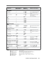
FCC Class A Notice
This equipment has been tested and found to comply with the limits for a Class A digital device, pursuant to part 15 of the FCC Rules.
Operation is subject to the following two conditions: (1) this device may not cause harmful interference, and (2) this device must accept any
interference received, including interference that may cause undesired operation. The Class A limits are designed to provide reasonable
protection against harmful interference when the equipment is operated in a commercial environment. This equipment generates, uses,
and can radiate radio frequency energy and, if not installed and used in accordance with the instruction manual, may cause harmful
interference to radio communications. Operation of this equipment in a residential area is likely to cause harmful interference, in which
case the user will be required to correct the interference at his own expense.
N
RGBS
RGBHV
This unit was tested with shielded cables on the peripheral devices. Shielded
cables Gmust be used
with theR unit to ensure
compliance
with
B
R
B
G
/B-Y
/R-Y
/Y
/B-Y
/R-Y
/Y
FCC emissions limits.
声明
所使用电源为 A 级产品,在生活环境中,该产品可能会造成无线电干扰。在这种情况下,可能需要用户对其干扰采取切实可行的措施。
H/
HV
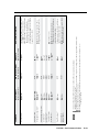
Installation
V
H/
HV
Component Video (Y, R-Y, B-Y)
RGsB
Step 1
R
/R-Y
Refer to the application examples at the end of this
section. If connected to a power source, turn off
power to the scaler, the input and output devices,
and remove power cords.
G
/Y
H/
HV
V
B
/B-Y
V
R
/R-Y
G
/Y
H/
HV
V
B
/B-Y
RGB
Output 15-pin HD connector
Step 2
Install the four rubber feet on the bottom of the
DVS 304 scaler, or mount the scaler in a rack (see
chapter 2 “Installation and Operation”).
N You can connect both outputs simultaneously
to two different displays. The sync format is
the same for both outputs.
Step 3
Step 5 (for DVS 304 A or
DVS 304 AD only)
Attach input devices to the scaler (see chapter 2
“Installation and Operation”).
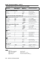
Rear panel video inputs
SDI
SDI input (DVS 304 D or AD models only)
Attach an SDI source to this optional BNC.
Input 1: Composite video
1
For detailed wiring instructions, see chapter 2
“Installation and Operation”.
VID
Balanced and unbalanced audio input
Input 2: Composite/S-video/YUVi/YUVp
(high impedance)
Tip
Sleeve
R-Y
2
Tip
Ring
Sleeves
Tip
Ring
AUDIO
Tip
Sleeve
R
R-Y
Balanced Input
(high impedance)
L
2
Unbalanced Input
B-Y
/C
AUDIO
R-Y
Y
/VID
B-Y
/C
R
2
Y
/VID
B-Y
/C
L
Y
/VID
Component Video (Y, R-Y, B-Y)
S-video (YC)
Composite Video
Connect up to four balanced or unbalanced stereo
audio input devices to the DVS 304 as shown below.
Each audio input has a 3.5 mm, 5-pole captive
screw connector.
Do not tin the wires!
Input 3: S-video
3
Balanced and unbalanced audio output
YC
Input 4: Composite/S-video/YUVi/YUVp/RGBcvS/
For unbalanced audio, connect the sleeve(s) to the center contact ground.
DO NOT connect the sleeve(s) to the negative (-) contacts.
Rear panel video outputs
Step 6
Output BNC connectors
RGBS
RGBHV
R
/R-Y
G
/Y
H/
HV
V
RGsB
G
/Y
B
/B-Y
R
/R-Y
G
/Y
H/
HV
V
B
/B-Y
Plug the DVS 304, and the input and output devices
into a grounded AC source, then turn on the input
and output devices.
Component Video (Y, R-Y, B-Y)
B
/B-Y
R
/R-Y
G
/Y
H/
HV
V
B
/B-Y
DVS 304 • Quick Start
H/
HV
AUDIO
R
Balanced Stereo Output
CAUTION
Attach output devices to the scaler.
R
/R-Y
Unbalanced Stereo Output
Tip
Ring
Sleeve (s)
Tip
Ring
L
Step 4
AUDIO
4
Tip
Sleeve (s)
Tip
See Caution
R
RGB scaled/RGB pass through
See Caution
L
RGB/R-Y,Y,B-Y/YC/VID
V
QS-1
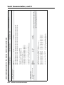
Quick Start — DVS 304, cont’d
Step 7
Use the front panel controls and LCD menu screens (shown in Appendix A) or RS-232 programming to
configure the scaler.
See chapter 2, “Installation and Operation” for more detailed operating procedures, chapter 3,
“Serial Communication” for programming information, and chapter 4, “Ethernet Control” for details on the
default Web pages.
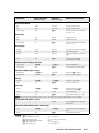
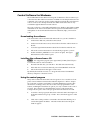
DVD Player
Laptop Computer
DVS 304
100-240V
.3A
Y
/VID
SDI
I
N
P
U
T
RGB/R-Y,Y,B-Y/YC/VID
R
/R-Y
G
/Y
B
/B-Y
4
1
50/60 Hz
R-Y
/C
VID
B-Y
2
YC
3
H/
HV
RGB/R-Y,Y,B-Y
V
RS-232
O
U
T
P
U
T
LAN
RESET
ACT
RS-232 Control
LINK
VCR
LCD Projector
Plasma Display
Document Camera
DVS 304 Application example
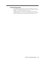
Sound System
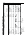
DVD Player
DVS 304A
100-240V
Laptop Computer
.3A
Y
/VID
SDI
AUDIO
L
1
R
L
2
INPUTS
R
L
3
R
L
4
R
OUTPUT
L
50/60 Hz
R
I
N
P
U
T
R-Y
/C
RGB/R-Y,Y,B-Y/YC/VID
R
/R-Y
G
/Y
H/
HV
V
4
1
VID
2
B-Y
3
YC
RGB/R-Y,Y,B-Y
B
/B-Y
O
O
U
U
TT
PP
U
U
TT
LAN
RS-232
RESET
ACT
LINK
RS-232 Control
VCR
LCD Projector
DSS Receiver
QS-2
DVS 304 • Quick Start
DVS 304 A Application example
Plasma Display
Table of Contents
Chapter One • Introduction . ..................................................................................................... 1-1
About this Manual..................................................................................................................... 1-2
About the DVS 304, DVS 304 A, DVS 304 D, and DVS 304 AD......................... 1-2
Controlling the DVS 304 video and RGB scaler..................................................................... 1-2
Features....................................................................................................................................... 1-2
Options and accessories............................................................................................................ 1-4
Chapter Two • Installation and Operation .................................................................... 2-1
Mounting the Scaler. ................................................................................................................ 2-2
Rear Panel Features................................................................................................................... 2-6
Front Panel Features................................................................................................................. 2-9
Input selection buttons............................................................................................................. 2-9
Menu navigation buttons......................................................................................................... 2-9
LCD menu display and controls............................................................................................... 2-9
Menus, Configuration, and Adjustments.................................................................. 2-10
Moving through menus by using front panel controls...................................................... 2-10
Menu overview. ....................................................................................................................... 2-10
Start auto image...................................................................................................................... 2-12
Input configuration................................................................................................................. 2-12
Input 1 video type.............................................................................................................. 2-13
Input 2 video type.............................................................................................................. 2-13
Input 3 video type.............................................................................................................. 2-13
Input 4 video type.............................................................................................................. 2-13
SDI input (SDI IN)................................................................................................................ 2-13
SDI de-interlacer options................................................................................................... 2-13
Picture control.......................................................................................................................... 2-14
Output configuration. ............................................................................................................ 2-14
Resolution and refresh rates.............................................................................................. 2-15
Output Signal..................................................................................................................... 2-15
Sync Polarity........................................................................................................................ 2-15
Audio configuration (DVS 304 A and DVS 304 AD only)................................................... 2-16
Memory preset......................................................................................................................... 2-16
Save memory preset........................................................................................................... 2-16
Clear (CLR) memory preset................................................................................................ 2-17
Recalling a preset............................................................................................................... 2-17
Input preset.............................................................................................................................. 2-17
IP configuration ...................................................................................................................... 2-17
Advanced configuration......................................................................................................... 2-18
Auto Image......................................................................................................................... 2-18
Blue mode........................................................................................................................... 2-18
Auto switch mode.............................................................................................................. 2-18
DVS 304 • Table of Contents TOC-i
PRELIMINARY
Tabletop/desktop placement. .................................................................................................. 2-2
UL guidelines for rack mounted devices........................................................................... 2-2
Rack mounting the DVS 304 ................................................................................................... 2-3
Rack mounting the DVS 304 A................................................................................................. 2-4
Application diagram. ................................................................................................................ 2-5
Table of Contents, cont’d
RGB Delay........................................................................................................................... 2-19
OSD label............................................................................................................................ 2-19
Test pattern......................................................................................................................... 2-19
Enhance mode.................................................................................................................... 2-19
Refresh Lock. ...................................................................................................................... 2-19
Auto Memory..................................................................................................................... 2-19
Picture-in-picture mode.......................................................................................................... 2-20
Changing the input............................................................................................................ 2-20
Using the swap feature...................................................................................................... 2-21
Exit menu.................................................................................................................................. 2-21
Resetting an Input. .................................................................................................................. 2-21
Resetting the Unit.................................................................................................................... 2-22
System Reset. .............................................................................................................................. 2-22
Front Panel Lockout (Executive mode). ...................................................................... 2-23
PRELIMINARY
IR 902 Infrared Remote Control....................................................................................... 2-24
Setting up the DVS to work with a Matrix switcher.......................................... 2-25
Using the DVS and matrix switcher after the DVS is
synchronized to the matrix switcher. ................................................................................... 2-27
Removing the Sync to Matrix Script.................................................................................. 2-28
Minimize synchronization problems without using
the Sync to Matrix feature................................................................................................. 2-28
Chapter Three • Serial Communication ......................................................................... 3-1
SIS™ Programmer’s Guide. ..................................................................................................... 3-2
Host-to-scaler and scaler to host communications............................................................... 3-2
Scaler-initiated messages..................................................................................................... 3-2
Using the command/response tables...................................................................................... 3-2
Copyright information......................................................................................................... 3-3
Password information.......................................................................................................... 3-3
Error responses..................................................................................................................... 3-4
References to errors (at command descriptions on the following pages)........................ 3-4
Symbol definitions..................................................................................................................... 3-5
Command/response table for SIS commands . ...................................................................... 3-8
Command/response table for IP control port commands.................................................. 3-15
Control Software for Windows®...................................................................................... 3-23
Downloading the software .................................................................................................. 3-23
Installing the software from a CD......................................................................................... 3-23
Using the control program..................................................................................................... 3-23
Using the help program. ........................................................................................................ 3-25
TOC-ii DVS 304 • Table of Contents
Chapter Four • Ethernet Control ......................................................................................... 4-1
Accessing and Using the Web Server. ............................................................................ 4-2
Navigating the Default Web Pages. ................................................................................ 4-3
Status .......................................................................................................................................... 4-3
System Status page............................................................................................................... 4-3
System Settings page........................................................................................................... 4-4
IP settings fields.............................................................................................................. 4-4
Scaler Settings page............................................................................................................. 4-6
Passwords.............................................................................................................................. 4-7
Firmware upgrade page...................................................................................................... 4-8
File Management ...................................................................................................................... 4-9
Control. ..................................................................................................................................... 4-10
User Control page.............................................................................................................. 4-10
Video/Audio breakaway (DVS 304 A or DVS 304 AD only)........................................ 4-10
Presets page........................................................................................................................ 4-11
Memory presets............................................................................................................ 4-11
Input presets (input 4 only).......................................................................................... 4-11
PIP Setup page.................................................................................................................... 4-12
Audio (DVS 304 A only)................................................................................................ 4-12
Appendix A • Menu System...................................................................................................... A-1
DVS 304 Menu System............................................................................................................ A-2
Default cycle menu .................................................................................................................. A-2
Main menu . .............................................................................................................................. A-2
Start Auto Image menu .......................................................................................................... A-3
Input Configuration menu ..................................................................................................... A-3
Picture Control menu .............................................................................................................. A-3
Output Configuration menu .................................................................................................. A-4
Audio Configuration menu .................................................................................................... A-4
Memory Preset menu .............................................................................................................. A-4
IP Configuration menu . .......................................................................................................... A-5
Advanced Configuration menu ............................................................................................. A-5
Exit menu .................................................................................................................................. A-5
Executive Mode menu . ........................................................................................................... A-6
Appendix B • Reference Material..........................................................................................B-1
Specifications................................................................................................................................B-2
Part Numbers and Accessories...........................................................................................B-5
Included parts.............................................................................................................................B-5
Accessories..................................................................................................................................B-5
Serial Digital Interface (SDI) Card Installation.........................................................B-6
All trademarks mentioned in this manual are the properties of their respective owners.
68-1039-01
Rev. B
11 08
DVS 304 • Table of Contents TOC-iii
PRELIMINARY
Configuration............................................................................................................................. 4-4
PRELIMINARY
Table of Contents, cont’d
TOC-iv DVS 304 • Table of Contents
DVS 304
1
Chapter One
Introduction
About this Manual
About the DVS 304, DVS 304 D, DVS 304 A, DVS 304 AD
Introduction
About this Manual
This manual discusses how to install, configure, and operate the Extron DVS 304
video and RGB scaler and how to operate the optional IR 902 infrared remote
control (part #70-495-01).
Throughout this manual the terms “DVS”, “digital video scaler”, and “scaler” are
used interchangeably to refer to the same product. All instances refer to all models
in the series unless noted otherwise.
About the DVS 304, DVS 304 A, DVS 304 D, and
DVS 304 AD
The DVS 304 series (DVS 304, DVS 304 A, DVS 304 D, and DVS 304 AD ) are
4-input, 1-output high performance RGB and video scalers offering 62 output
rates, including HDTV. These products provide scaling solutions for boardrooms,
conference rooms, and home theaters, as well as rental and staging applications.
The two DVS 304 scalers come in a half rack model (DVS 304) with an SDI option,
and a full rack model (DVS 304 A) with an SDI option and balanced/unbalanced
audio.
All versions of the DVS 304 can be controlled remotely using Extron’s Simple
Instruction Set (SIS™) commands via RS-232, or through an Ethernet LAN
connection using embedded Web pages.
The DVS 304 scales from composite video, S-video, component (Y, R-Y, B-Y) video,
and RGB video to computer-video (RGBHV/RGBS/RGsB) or HD component.
It can also output to two separate display devices via individually buffered BNC
and 15-pin HD connectors.
Controlling the DVS 304 video and RGB scaler
The DVS 304 can be controlled using one or more of the following methods:
• The front panel controls.
• A computer, a touch screen panel, or any other device that can send and
receive the serial communications through the RS-232 port. The Extron
Simple Instruction Set (SIS) is a set of simple keystroke commands that can
be used with any such devices, and Extron’s control software for Windows®
provides a graphical interface for controlling the scaler from a computer.
• The optional IR 902 remote control, replicating most of the front panel
controls.
• Ethernet control via IP Link, enabling the DVS 304 to be controlled and
pro-actively monitored over a LAN, WAN, or the Internet.
Features
Four inputs:
SDI video input (optional) — One BNC connector on the rear panel accepts
SDI video. During setup, the SDI input is assigned to input 1, 2, 3, or 4
(the default is none).
Input 1 — One BNC connector on the rear panel accepts composite video.
Input 2 — Three BNC connectors on the rear panel accept composite video,
S-video, or component video.
Input 3 — A 4-pin mini-DIN connector accepts an S-video signal.
Input 4 — A 15-pin HD connector accepts an RGB, component video,
1-2
DVS 304 • Introduction
S-video or composite video signal.
RGB and video scaling — Provides a high performance scaling engine with
the capacity to scale standard definition video, high definition video, and
computer-video signals up or down in resolution.
Picture Control — Allows size, position, brightness, contrast, color, tint, detail,
zoom and pan adjustments for each input.
Picture-In-Picture — Allows for a low resolution (YUVi, S-video, and composite
video) input or a high resolution (VGA and YUVp) input for the primary or
secondary picture.
Memory and input presets — Memory presets save sizing, positioning, and picture
control settings.
Input presets (on input 4 only) save input configuration, picture control, and
OSD (on-screen display) text.
Auto image™ — Auto image automatically sizes, centers, and optimizes the image
to that of the scaled output rate, filling the window with the image.
IP Link® — IP Link-enabled products offer an integrated Web server with high
performance architecture, global compatibility with industry standard
Ethernet communication protocols, multi-user support, and a Web-based
asset management application specifically designed to work with products
that include IP Link technology.
Buffered video outputs — Five rear-panel BNC connectors and one VGA-type
15-pin HD connector provide connections for RGB or Y, R-Y, B-Y output.
Both outputs (the BNCs and 15-pin HD connector) are active at all times for
simultaneous output.
Device control — The scaler has four methods of control; by the scaler’s front
panel, via a computer or other RS-232 control device, using the optional IR
902 remote control, or via Signal Enhancements Windows Control Program.
Scaled outputs — The DVS 304 offers 62 different output rates.
RS-232 configuration — The DVS 304 can be configured by using the Extron control
software for Windows or by using a third party control system.
Front panel security lockout (executive mode) — To prevent accidental changes
to the unit’s settings, the DVS 304 provides front panel lockout of all controls
except input switching.
3:2 pull down detection for NTSC and 2:2 film detection for PAL video sources
— These patented, advanced film mode processing features, help maximize
image detail and sharpness for video sources that originated from film.
When film is converted to NTSC video, the film frame rate has to be matched
to the video frame rate in a process called 3:2 pull down. “Jaggies” and other
image artifacts can result if conventional de-interlacing techniques are used
on
film-source video. The DVS 304’s advanced film mode processing recognizes
signals that originated from film. The DVS 304 then applies video processing
algorithms that optimize the conversion of video that was made with the
3:2 pull down process. This results in richly detailed images with sharply
defined lines. A similar process is used for PAL film-source video.
Versatile mounting options — The DVS 304 and DVS 304 D are 1U high, half rack
wide rack mountable devices. Alternatively, they can be placed on a table or
other furniture. Rubber feet and rack mounting hardware are included.
The 1U high and full rack DVS 304 A and DVS 304 AD (audio models) can be
rack mounted using included rack/through-desk mounting brackets.
DVS 304 • Introduction
1-3
Introduction, cont’d
Options and accessories
The DVS 304’s optional equipment includes:
1-4
•
IR 902 remote control — Extron’s IR 902 (part #70-495-01) is an infrared
remote control which replicates most of the front panel controls of the
DVS 304 (except the Menu and Next buttons).
•
SDI input card — Serial digital interface (SDI) input can be added to the
DVS 304 model by the installation of an SDI input card (part #70-168-01).
DVS 304 • Introduction
DVS 304
2
Chapter Two
Installation and Operation
Mounting the Scaler
Rear Panel Features
Front Panel Features
Menus, Configuration, and Adjustments
Resetting an Input
Resetting the Unit
System Reset
Front Panel Lockout (Executive Mode)
IR 902 Infrared Remote Control
Setting up the DVS to work with a Matrix Switcher
Installation and Operation
Mounting the Scaler
The DVS 304 is 1U high, half rack wide, and is rack mountable. Alternatively, it can
be placed on a table or other furniture. Rubber feet and rack mounting hardware
are included.
The 1U high and full rack DVS 304 A (audio model) can be rack mounted using
included rack/through-desk mounting brackets.
Tabletop/desktop placement
Four self-adhesive rubber feet are included with the DVS 304. For tabletop use,
attach one foot to each corner of the bottom side of the unit and place the unit in the
desired location.
UL guidelines for rack mounted devices
The following Underwriters Laboratories (UL) guidelines pertain to the safe installation of the
DVS in a rack.
2-2
1.
Elevated operating ambient temperature — If installed in a closed or multi-unit
rack assembly, the operating ambient temperature of the rack environment may
be greater than room ambient temperature. Therefore, install the DVS 304 in an
environment compatible with the maximum ambient temperature
(Tma = +122 °F, +50 °C) specified by Extron.
2.
Reduced air flow — Install the equipment in a rack so that the amount of air flow
required for safe operation of the equipment is not compromised.
3.
Mechanical loading — Mount the equipment in the rack so that a hazardous
condition is not achieved due to uneven mechanical loading.
4.
Circuit overloading — Connect the equipment to the supply circuit and consider
the effect that circuit overloading might have on overcurrent protection and
supply wiring. Appropriate consideration of equipment nameplate ratings should
be used when addressing this concern.
5.
Reliable earthing (grounding) — Maintain reliable grounding of rackmounted equipment. Pay particular attention to supply connections other
than direct connections to the branch circuit (e.g. use of power strips).
DVS 304 • Installation and Operation
Rack mounting the DVS 304
1.
If feet were installed on the bottom of the DVS 304, remove them.
2.
Place the DVS 304 on one half of the 1U (one unit high, one unit wide) rack
shelf (part #60-190-01). Align the front of the DVS 304 with the front of the
shelf, and align the threaded holes on the bottom of the DVS 304 with the
holes in the rack shelf.
3.
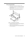
Attach the DVS 304 to the rack shelf with the two provided 4-40 x 1/16"
machine screws. Insert the screws from the underside of the shelf, and
securely fasten them into diagonally-opposite corners (figure 2-1).
False front panel
uses 2 front holes.
(2) 4-40 x 3/16" Screws
Use 2 mounting holes on
opposite corners.
Figure 2-1 — Rack mounting a half rack device
4.
Attach the false front panel (provided with the universal rack shelf) to the
unoccupied side of the rack (as shown above), or install a second half-rackwidth device in that side by repeating steps 1 – 3.
5.
Attach the rack shelf to the rack using four 10-32 x 3/4" bolts (provided).
Insert the bolts through #10 beveled washers, then through the holes in the
rack ears and rack (figure 2-1).
DVS 304 • Installation and Operation
2-3
Installation and Operation, cont’d
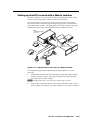
Rack mounting the DVS 304 A
To mount the DVS 304 A in a rack, do the following:
1.
If feet were installed on the bottom of the DVS 304, remove them.
2.
Attach the included rack/through-desk mounting brackets
(part #70-077-03) to the unit using eight machine screws supplied with the
mounting kit.
Rack Mount
Bracket
Figure 2-2 — Attach the mounting brackets and install in rack
3.
2-4
Insert the unit into the rack and align the holes in the mounting brackets with
the holes in the rack. Use four machine screws to attach the brackets to the
rack.
DVS 304 • Installation and Operation
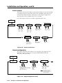
Application diagram
The diagram shown below is an example of a typical DVS 304 AD application with
cable connections.
Digital Tape Deck
w/ SDI Output
RS-232 Control
TCP/IP
Network
Sound System
2
RS
B
/B-Y
G
/Y
R
/R-Y
Y
R/C
Y
/VID
SD
D
/VI
YC
-Y/
Y,B
-Y,
B/R
RG
O
U
T
P
U
T
-23
N
LA
T
SE
RE
K
LIN
AC
T
V
H/
HV
4
I
B/
,B
Y,Y
-Y
R-
RG
YC
I
N
P
U
T
Y
BVID
3
2
1
UT
TP R
OU
L
O
AU
L
TS
PU L
3
4
DI
Projector
(RGB)
R
R
IN
L
.3A
Extron
DVS 304 A
Digital Video Scaler
w/ Audio
0V
-24
100
L
60
50/
1
2
R
R
Hz
Audio
Laptop
(RGB)
DSS Receiver
(S-video)
DVD
(Component)
VCR
(Video)
Figure 2-3 — Application diagram example of the DVS 304 AD
DVS 304 • Installation and Operation
2-5
Installation and Operation, cont’d
Rear Panel Features
The rear panels of the DVS 304 D and DVS 304 AD models (figures 2-4 and 2-5)
contain all of the possible connectors available on the DVS 304 series of scalers.
4a
100-240V
.3A
Y
/VID
SDI
I
N
P
U
T
AUDIO
L
1
R
L
2
INPUTS
L
R
3
R
L
4
OUTPUT
R
L
R
50/60 Hz
1
7
RGB/R-Y,Y,B-Y/YC/VID
R
/R-Y
G
/Y
H/
HV
V
B
/B-Y
4
VID
1
2
B-Y
/C
4
3
R-Y
2
YC
3
RGB/R-Y,Y,B-Y
6
5
O
O
U
U
TT
PP
U
U
TT
LAN
ACT
9
8
RS-232
RESET
LINK
10
11
Figure 2-4 — DVS 304 AD rear panel connectors
4a
100-240V
.3A
Y
/VID
SDI
I
N
P
U
T
VID
4
1
B-Y
/C
RGB/R-Y,Y,B-Y/YC/VID
R
/R-Y
G
/Y
H/
HV
V
B
/B-Y
4
1
50/60 Hz
11
7
R-Y
2
YC
3
5
RGB/R-Y,Y,B-Y
6
RS-232
O
U
T
P
U
T
LAN
RESET
ACT
9
8
LINK
10
Figure 2-5 — DVS 304 D rear panel power connector
a
AC power connector — Plug a standard IEC power cord into this connector
to connect the scaler to a 100 to 240 V AC, 50 Hz or 60 Hz power source.
The front panel control and input selection buttons light in sequence during
power-up.
b
Audio input — Plug up to four, 3.5 mm, female, five-pole, captive screw
connectors for balanced/unbalanced variable audio input.
c
Audio output — Plug one, 3.5 mm, female, five-pole captive screw connector
for balanced/unbalanced variable audio output.
d
Video input 1: Composite video — Connect a composite video
signal to this female, BNC connector.
Ü
Optional SDI (serial digital interface) input connector — Connect
an SDI signal to this female BNC connector. During setup, the SDI
input can be assigned to one of the other unused inputs.
e
Video input 2: Composite/S-video/Component — Connect composite video,
S-video, and component video signals. Connect cables for the appropriate
signal type, as shown here.
Y
/VID
f
2
Y
/VID
B-Y
/C
R-Y
2
R-Y
SDI
Y
/VID
B-Y
/C
2
B-Y
/C
R-Y
Video input 3: S-video — Connect an S-video signal to this
4-pin, mini-DIN female connector.
3
2-6
DVS 304 • Installation and Operation
VID
Component Video (Y, R-Y, B-Y)
S-video (YC)
Composite Video
1
YC
g
Video input 4: RGB/R-Y, Y, B-Y/YC/VID — Connect RGBHV, RGBS, RGsB,
RGBcvS, YUVi, YUVp, S-video and composite video through this 15-pin HD
connector. See pin configurations below.
Signal Input 4 Pin Configuraton
5
RGB/R-Y,Y,B-Y/YC/VID
1
10
6
4
15
Pin 1 Pin 2 Pin 3 Pin 13 Pin 14
R
G
B
H
V
R
G
B
S
R
G
B
R-Y Y
B-Y
Y
C
Vid
RGBHV
RGBS
RGsB
YUV
S-video
Video
11
N Equipment following the SCART interconnection standard may be connected to
the RGBcvS input cabling configuration.
h
RGB (RGBHV, RGBS, RGsB) or HD component (R-Y, Y, B-Y) video BNC
outputs — Connect coaxial cables from a display device to these BNCs for a
scaled or pass-through RGB or a scaled component video output. The output
can be scaled to 62 different output rates (see table on page 2-15).
RGBS
RGBHV
R
/R-Y
G
/Y
H/
HV
V
RGsB
R
/R-Y
G
/Y
B
/B-Y
R
/R-Y
G
/Y
H/
HV
V
B
/B-Y
Component Video (Y, R-Y, B-Y)
B
/B-Y
R
/R-Y
G
/Y
H/
HV
V
B
/B-Y
RGB or HD component (R-Y, Y, B-Y) 15-pin HD video output —
Connect an RGB video display or HD component video display RGB/R-Y,Y,B-Y/YC/VID
to this HD 15-pin connector.
H/
HV
V
N Both h outputs are buffered and can be connected
simultaneously to two different displays. The sync and video formats will
be the same for both outputs.
4
i
Reset button and LED — A recessed button that allows for manual resets
using an Extron Tweeker, pointed stylus or ballpoint pen. The unit can be reset
to four modes (see “Resetting the Unit” later in this chapter for additional
information).
The green LED flashes to show the reset mode indicators and that power is
on.
connector — Plug an RJ-45 jack into this socket to connect the unit to a
jLAN
computer network. Use a patch cable to connect to a switch, hub, or router.
See the following page for wiring information.
LAN Activity LED — A blinking yellow LED indicates LAN activity.
Link LED — The green LED lights to indicate a good LAN connection.
DVS 304 • Installation and Operation
2-7
Installation and Operation, cont’d
Pins:
Straight-through Cable
12345678
(for connection to a switch, hub, or router)
End 1
Side View
Insert
Twisted
Pair Wires
Pin
1
2
3
4
5
6
7
8
RJ-45 Connector
Wire Color
white-orange
orange
white-green
blue
white-blue
green
white-brown
brown
End 2
Pin
1
2
3
4
5
6
7
8
Wire Color
white-orange
orange
white-green
blue
white-blue
green
white-brown
brown
Crossover Cable
(for direct connection to a PC)
End 1
Pin
1
2
3
4
5
6
7
8
Wire Color
white-orange
orange
white-green
blue
white-blue
green
white-brown
brown
End 2
Pin
1
2
3
4
5
6
7
8
Wire Color
white-green
green
white-orange
blue
white-blue
orange
white-brown
brown
Figure 2-6 — Wiring the RJ-45
k
Remote (RS-232/contact closure) 9-pin port — This connector
provides for two-way RS-232 communication. See chapter 3,
“Serial Communication”, for information on how to install and
use the control software and SIS commands.
RS-232
9
1
6
The default protocol is 9600 baud, 1 stop bit, no parity, and no flow control.
The rear panel RS-232 9-pin D female connector has the following pin
assignments:
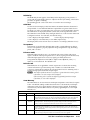
Pin RS-232 function
2-8
5
1
2
3
4
5
6
7
8
9
Input #1
Tx
Rx
Input #2
Gnd
Input #3
Input #4
–
–
Description
Contact closure
Transmit data
Receive data
Contact closure
Signal ground
Contact closure
Contact closure
No connection
Reserved
The Remote connector also provides a way to select an input using a remote
contact closure device. Contact closure control uses pins on the RS-232
connector that are not used by the RS-232 interface (see preceding table).
To select a different input number using a contact closure device, short the pin
for the desired input number to logic ground (pin 5).
DVS 304 • Installation and Operation
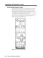
Front Panel Features
The front panel buttons, controls, LCD, and infrared sensor are found on all models
of the DVS 304 scaler series. The LEDs beside each input button will light green
when the button is pressed.
DVS 304
DIGITAL VIDEO SCALER
ADJUST
1
2
3
4
MENU
NEXT
IR
1
2
4
3
5
6
7
Figure 2-7 — DVS 304 and DVS 304 A front panel
Input selection buttons
a
Input LEDs — The LED of the selected input lights when pressed. A blinking
LED indicates an audio breakaway input (audio models only).
Composite input button — Input 1 selects composite video input.
S-video input button — Input 3 selects the S-video input.
Composite/YC/component input button — Input 2 selects composite video,
YC, or component video input.
Universal input button — Input 4 selects the RGB scaled (RGBHV, RGBS,
RGsB), RGB pass-through, YUVi, YUVp, S-video and composite video.
Menu navigation buttons
b
Menu button — Use this button to enter and move through the main menu
system in the DVS 304. See the “Menus, Configuration, and Adjustments”
section in this chapter for details.
c
Next button — Use this button to step through the submenus in the
DVS 304 menu system. See the “Menus, Configuration, and Adjustments”
section in this chapter for details.
LCD menu display and controls
d
LCD — Displays configuration menus and status information. See the
“Menus, Configuration, and Adjustments” section in this chapter for details.
e
Infrared sensor — This sensor is used to receive infrared (IR) signals from the
IR 902 remote control. See the “IR 902 Infrared Remote Control” section in
this chapter for details.
f
Adjust horizontal ([) knob — In the menu system, rotate this knob to scroll
through menu options and make adjustments.
g
Adjust vertical ({) knob — In the menu system, rotate this knob to scroll
through menu options and make adjustments.
DVS 304 • Installation and Operation
2-9
Installation and Operation, cont’d
Menus, Configuration, and Adjustments
Scaler configuration and adjustments can be performed by using the embedded
Web pages and the Windows-based control program (see chapter 3, “Serial
Communication” for details) or by using the front panel controls and the menus
that are displayed on the DVS 304’s LCD screen. These menus are used primarily
when the scaler is first set up.
Moving through menus by using front panel controls
Menu button — Press the Menu button to activate menus and scroll through the
eight main menus.
Next button — Press the Next button to move between the submenus of a selected
main menu. Pressing the Next button during input configuration causes the
current input’s number and format type to be displayed on the LCD
Adjust ([,{) knobs — In configuration mode, rotate the Adjust horizontal ([)
knob and Adjust vertical ({) knob to scroll through submenu options and to
make adjustment selections. Refer to the flowcharts in this chapter and to specific
sections for explanations on knob adjustments.
Menu overview
The default menus appear on the LCD when no adjustments are actively being
made. They cycle between the screen showing the model of the scaler (DVS 304 or
DVS 304 A) and the screen that shows the active input’s number and video format,
as shown below.
Default Cycle
2 sec.
Power
on
EXTRON
DVS 304
2 sec.
60-736-01
FW ver. 1.xx
2 sec.
INPUT 1
COMPOSITE
2 sec.
OUTPUT
1024 x 768@60
Figure 2-8 — Default menus
N From any menu or submenu, after 20 seconds of inactivity the DVS 304 will
save all adjustment settings and time-out to the default menus.
The main menus are shown on the following pages. Use the Menu button to scroll
between them.
N If no signal is present on the currently selected input, NO SIGNAL appears in
place of a signal value, e.g. INPUT 4 NO SIGNAL.
2-10
DVS 304 • Installation and Operation
Default Cycle
2 sec.
Power
on
EXTRON
DVS 304
2 sec.
60-736-01
FW version 1.00
2 sec.
INPUT 1
COMPOSITE
2 sec.
OUTPUT
1024 x 768@60
MENU
START AUTO
IMAGE ON IN1
MENU
INPUT
CONFIG
MENU
PICTURE
CONTROL
MENU
OUTPUT
CONFIG
MENU
AUDIO
CONFIG
(Audio models only)
MENU
MEMORY
PRESETS
MENU
IP
CONFIG
MENU
ADVANCED
CONFIG
MENU
MENU
TO EXIT MENU
PRESS NEXT
NEXT
Figure 2-9 — Main menus
N To return to the default screens, allow the DVS 304 to time-out (after 20
seconds). Alternatively, press the Menu button repeatedly until the Exit menu
appears, then press the Next button.
N Submenus are accessed from a main menu by pressing the Next button.
When in a submenu, press the Menu button to go out of the submenu and back
to the active main menu.
DVS 304 • Installation and Operation
2-11
Installation and Operation, cont’d
Start auto image
Auto imaging allows you to “auto size” and “auto center” the selected image to
fill the screen. The processor measures the sync frequencies of an incoming video
source and uses an internal table to set the active image area, total image area, and
the sampling frequency.
If an unknown input is connected to the DVS 304, the processor measures and
estimates the resolution of the incoming video.
To turn on this feature, select the Advanced Config menu and choose “On”.
Start auto imaging on a selected input by pressing “Next” after the Start Auto
Image menu.
Default Cycle
2 sec.
INPUT 1
COMPOSITE
OUTPUT
1024 x 768@60
2 sec.
START AUTO
IMAGE ON IN1
MENU
NEXT
NEXT
PRESS NEXT
TO START
Figure 2-10 — Start auto image menu
N An input with a vertical refresh rate less than 40 Hz will have to be manually
centered and sized, using H/V Start and H/V Active under the Input Config
menu. When a rate with a low vertical refresh rate (e.g. 720p 29.9 Hz) is applied
and an Auto Image command is issued, the DVS 304 will refer to default values
instead of performing a true Auto Image.
Input configuration
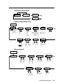
The following flowchart provides an overview of the Input Configuration
submenus and the options for each setting.
START AUTO
IMAGE ON IN1
MENU
Displays only when applicable
INPUT
CONFIG
NEXT
Input 1 can only accept
composite video. Input 3
can only accept S-video.
Only Inputs 2 and 4 can
be configured for
different video types,
although an SDI input
can be assigned to any
input.
INPUT 2
YUVi
NEXT
INPUT 4
RGB SCALED
NEXT
NEXT
N The SDI input signal can be
assigned to any input. Once
assigned to a specific input,
only an SDI signal can be
accepted on that input. SDI
can be disabled by
selecting the *.
Displays only when applicable
NEXT
FILM MODE
<OFF> ON
SDI DE-INTER
FIELD STNDRD
NEXT
Assign SDI to Input #
• 1, 2, 3, 4, * (none)
Select video format
• Composite
• S-video
• RGBcvS
• YUVi
• YUVp
• RGB scaled
• RGB pass
• Auto detect
Select video format
• Composite
• S-video
• YUVi
• YUVp
• YUV Auto
Displays only when applicable
SDI INPUT
<*> 1 2 3 4
N SDI De-interlacing options:
• Field Standard
• Field Flip
Displays only when applicable
NEXT
H ACTIVE V
XXX
XXX
NEXT
H START V
50
33
NEXT
TTLPIX PHASE
XXXX
08
For YUVp or RGB input only
Film mode
Turn On or Off for low
resolution devices.
Not for use with
YUVp or RGB
inputs.
Horizontal
active pixels
Specify the
width in pixels
of the active
image area
sampled.
Vertical active
lines
Specify the
height in lines of
the active image
area sampled.
Horizontal start
Select for the
left edge of the
active video.
Vertical start
Select for the
top edge of the
active video.
Figure 2-11— Input Configuration menus
2-12
DVS 304 • Installation and Operation
Total pixels
Specify the
width in pixels of
the total image
area sampled.
Pixel phase
Adjust the pixel
sampling point
for a selected
input.
ASPECT RATIO
4x3
Aspect ratio options
• 4x3
• 16 x 9
NEXT
N Only inputs 2 and 4 offer selectable video types. From the Input Configuration
menu, pressing the Next key successively displays submenus with the input
video types for Inputs 2 and 4. The SDI input (where applicable) can be
assigned to any input from the Input Configuration menu.
Input 1 video type
Input 1 can only input composite video, no other video types are selectable for this
input.
Input 2 video type
Rotate either the Adjust horizontal ([) knob or Adjust vertical ({) knob while in
the Input 2 submenu to select the appropriate video format (composite, S-video,
YUV, YUVp, YUV Auto) for input 2.
When input 2 is set to YUV Auto, the scaler will detect if YUVi or YUVp is applied
and will set the input accordingly. The default is YUVi video.
Input 3 video type
Input 3 can only input S-video, no other video types are selectable for this input.
The SDI input (if any) can be assigned to any input from the Input Configuration
menu.
Input 4 video type
Rotate the Adjust horizontal ([) knob while in the Input 4 submenu to select the
appropriate video format (Composite, S-video, RGBcvS, YUV, YUVp, RGB scaled,
RGB pass-through, Auto detect).
When input 4 is set as “auto detect”, the scaler will switch to the new configuration
whenever it detects an input type change. The default is RGB scaled.
SDI input (SDI IN)
Rotate either the Adjust horizontal ([) knob or Adjust vertical ({) knob while in
the SDI Input submenu to select the input # for the SDI input. The SDI input can be
assigned to inputs 1, 2, 3, 4, or none (*). The default is none.
N After the SDI input is no longer assigned to an input, either because it has been
assigned to a new input or is set to none, the input reverts back to the last video
type that was assigned to it.
SDI de-interlacer options
Rotate either the Adjust horizontal ([) knob or Adjust vertical ({) knob while in
the SDI Deinter submenu to set the appropriate de-interlacing method (Standard
or Flip). If the SDI input is displayed with a significant amount of jaggies, use this
setting to flip the odd and even fields when de-interlacing the incoming SDI signal.
The default is Standard.
DVS 304 • Installation and Operation
2-13
Installation and Operation, cont’d
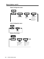
Picture control
The Picture Control menu includes all of the picture settings for the scaler including
positioning, sizing (horizontal and vertical control), brightness and contrast, color
saturation, tint, detail (sharpness of the picture), and zooming (see figure 2-12).
The pan feature is only available when zoom is over 100%.
Color, tint and pan controls are available to applicable signals only.
INPUT
CONFIG
MENU
Tint adjustment applicable only for
NTSC composite or S-Video inputs
PICTURE
CONTROL
H POS V
000
000
NEXT
Horizontal
position
Adjust
horizontal
image
position.
H SIZE V
1024
768
NEXT
Vertical
position
Adjust
vertical
image
position.
Horizontal
sizing
Adjust
horizontal
image
sizing.
NEXT
BRIGHT CONT
064
064
NEXT
TINT
064
NEXT
Tint
Color
Adjust color Adjust tint
of image.
of image.
Brightness Contrast
Adjust image Adjust image
brightness. contrast.
Vertical
sizing
Adjust
vertical
image
sizing.
COLOR
064
Only applicable when zoom is over 100 %
NEXT
H
PAN V
000
000
NEXT
ZOOM
100%
DETAIL
064
NEXT
Zoom
Allows for 100-200% zoom
while the aspect ratio
remains unchanged.
Pan
Move the “zoomed”
image horizontally or
vertically. Available only
when zoom is set over
100%.
Detail
Adjust sharpness of
the image.
Figure 2-12— Picture control menu
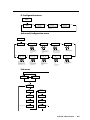
Output configuration
The output configuration menu allows you to select the scaler output rate from
different resolutions, refresh rates, sync types (RGBHV, RGBS, RGsB and
Y, B-Y, R-Y), and sync polarity.
PICTURE
CONTROL
MENU
OUTPUT
CONFIG
NEXT
RESOLUTION
1024x768@60
NEXT
Resolution refresh rate
• See the scaler output table on next page
for available combinations of resolutions
and refresh rates.
Default: 1024 x 768@60 Hz
FORMAT
RGBHV
Output type
• RGBHV (default)
• RGBS
• RGsB
• Y, R-Y, B-Y
NEXT
H SYNC V
NEG
NEG
Sync polarity combinations
• H Neg V Neg (default)
• H Neg V Pos
• H Pos
V Neg
• H Pos
V Pos
NOTE
Figure 2-13— Output Configuration menu
2-14
DVS 304 • Installation and Operation
NEXT
This information only appears
when the sync polarity is
applicable and is based on the
selected output format.
Resolution and refresh rates
Rotate the Adjust horizontal ([) knob while in this submenu to select one of the
available combinations of output resolutions and refresh (vertical scanning) rates.
Rotate the Adjust vertical ({) knob while in this submenu to select one of the
available refresh rates.
The default resolution and rate for the DVS 304 is 1024 x 768 @ 60Hz.
Available Scaler Output Resolutions and Rates
Resolution
24 Hz
50 Hz
60 Hz
72 Hz
75 Hz
96 Hz
100 Hz
120 Hz
640 x 480
X
X
X
X
X
X
800 x 600
X
X
X
X
X
X
852 x 480
X
X
1024 x 768
X
X
X
X
1024 x 852
X
X
X
X
1024 x 1024
X
X
X
1280 x 768
X
X
X
1280 x 1024
X
X
X
1360 x 765
X
X
X
1365 x 768
X
X
X
1365 x 1024
X
X
1366 x 768
X
X
1400 x1050
X
X
1600 x 1200
X
X
480p
X
X
576p
X
720p
X
X
1080i
X
X
X
X
1080p
X
X
X
1440 x 900
X
1680 x 1050
X
1280 x 800
X
X
X
Output Signal
Using either the Adjust horizontal ([) or Adjust vertical ({) knob, select the output
video format required by the display: RGBHV (default); RGBS; RGsB; Y, R-Y, B-Y.
Sync Polarity
The display or projector may require a particular combination of horizontal (H) and
vertical (V) sync signal polarities.
Select the appropriate combination of positive or negative H and V sync by
rotating either the Adjust horizontal ([) or Adjust vertical ({) knob.
N If the previous output signal was specified as RGsB or Y, R-Y, B-Y, or RGBS,
this submenu will not be displayed because this menu is only active for RGBHV.
DVS 304 • Installation and Operation
2-15
Installation and Operation, cont’d
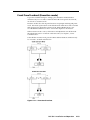
Audio configuration (DVS 304 A and DVS 304 AD only)
Audio Configuration allows the input level to be adjusted between –15 dB to +9 dB
for each audio input.
OUTPUT
CONFIG
MENU
AUDIO
CONFIG
NEXT
IN1 LEVEL
0dB
NEXT
(audio models only)
Input level
Adjust the input
gain/attenuation from
-15dB to +9dB of the
selected input.
Figure 2-14 — Audio configuration menu
Volume control is available through SIS commands or IR remote control.
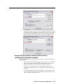
Memory preset
The memory preset feature saves the current values for image parameters such as
color, tint, contrast, brightness, detail, aspect ratio, horizontal start, vertical start,
horizontal active, vertical active, phase, total pixels, horizontal position, vertical
position, horizontal size, vertical size and zoom.
The following flowchart provides an overview of the Memory Preset submenus and
the options for each setting.
Figure 2-15 — Memory present menu
N The presets will only save the sizing, centering, and picture control information.
Save memory preset
From this submenu, the picture control information for the currently selected input
can be saved to memory. Up to three memory presets can be saved per input.
1.
Using either the Adjust horizontal ([) or Adjust vertical ({) knob, select (< >)
either N/A, 1, 2, or 3 to select a preset. The default is <N/A>.
2.
To save the preset, press the Next button.
N The presets are saved in nonvolatile memory, so powering down the DVS 304
will not lose the presets. Saving a preset by pressing the Next button will also
advance to the next submenu (Clear memory preset).
2-16
To exit the Save memory preset function without saving a preset, press Menu.
DVS 304 • Installation and Operation
Clear (CLR) memory preset
From this submenu, up to three saved presets for the currently selected input can
be cleared from memory.
1.
Using either the Adjust horizontal ([) or Adjust vertical ({) knob, select (< >)
either N/A, 1, 2, or 3 to select a preset. The default is <N/A>.
2. To clear the preset, press the Next button.
N Clearing a preset by pressing the Next button will also cause a return to the
Memory Preset menu.
To exit the Clear memory preset function without clearing a preset, press Menu.
Recalling a preset
Recalling a saved preset requires that the desired input be currently selected and
that the input button be pressed successively to activate each saved preset (up to
three). Each saved preset will display the message “Input #X Memory Y”, where
“X” refers to the input (1 to 4) and “Y” refers to the preset (1 to 3).
In the absence of any saved presets, the “Input #X Memory Y” message will not be
displayed for those presets.
N The presets are specific to a selected output rate. If the output rate is
subsequently changed, the previously saved preset will have no effect on the
video output. However, if the original output rate is later restored for a saved
preset, the preset will re-apply to that output rate.
Input preset
Input preset saves current values for parameters such as input type, color, tint,
contrast, brightness, detail, aspect ratio, horizontal start, vertical start, horizontal
active, vertical active, phase, total pixels, horizontal position, vertical position,
horizontal size, vertical size, zoom, and OSD text.
IP configuration
The IP Configuration menu displays the IP address of the unit, the Subnet mask,
and Gateway IP address.
MEMORY
PRESETS
MENU
IP
CONFIG
NEXT
I 196.168
P 254.254
View IP address
of the unit.
NEXT
S 255.255
M 000.000
View the subnet mask
of the unit.
NEXT
G 000.000
M 000.000
NEXT
View gateway IP address
of the unit.
Figure 2-16— IP Configuration menu
To change an IP address, do the following:
1.
Press and hold the Input 4 and Next buttons simultaneously for 2 seconds.
This introduces the Setup mode.
2.
Change the flashing octet selection by using the Adjust vertical ({) knob.
Change the selection numbers by using Adjust horizontal ([) knob.
3.
Press the Menu button to return to the IP address setup and the Next button
to select another address setup.
4.
Press the Menu button to save and exit.
The IP configuration menu “times out” if there is no activity for over 10 seconds.
DVS 304 • Installation and Operation
2-17
Installation and Operation, cont’d
Advanced configuration
The following flowchart provides an overview of the Advanced Configuration
submenus and the options for each setting.
IP
CONFIG
MENU
ADVANCED
CONFIG
NEXT
AUTO IMAGE
<OFF> ON
BLUE MODE
<OFF>
ON
NEXT
Auto imaging
When auto image is on,
the unit automatically
sizes and centers each
new input.
NEXT
AUTO MEMORY
<OFF>
ON
NEXT
Auto Memory
When set to on, the unit
automatically saves the
input and picture control
settings for inputs 2 and 4.
REFRESH LOCK
<OFF>
ON
Refresh Lock
When set to on, the
vertical ouptut rate will
lock on to the incoming
vertical refresh rate.
NEXT
ENHANCE MODE
<OFF>
ON
Enhance Mode
When set to on, the
automatic gain control of
the input signal is
enabled.
NEXT
Auto switching
The unit switches to the
highest numbered input,
which as a signal present
when auto switching is on.
Blue mode
When set to on, only the
sync and blue video
signals are passed to the
display
NEXT
AUTO SWITCH
<OFF>
ON
NEXT
TEST PATTERN
OFF
Test patterns
• Off
• Crop
• Alternating pixels
RGB DELAY
0.0 sec.
NEXT
RGB delay
Can be set from 0 to 5.0
seconds in 0.5 steps.
NEXT
OSD LABEL
2 sec.
OSD label duration
Can be set from 0 OFF
(no OSD) to 5 seconds in
1 second steps.
• Color bars
Figure 2-17— Advanced Configuration menu
Auto Image
When enabled and a new input frequency is detected, the DVS will first apply an
existing Auto Memory for the signal (if Auto Memory is enabled), or if no entry
exists, will perform an automatic Auto Image on the new signal.
With Auto Image disabled, the DVS 304 will apply default values to a new input if
no Auto Memory exists (if Auto Memory is enabled). Default is off.
Please see the table in the Auto Memory section for a full description of the
interaction between the Auto Image and Auto Memory settings.
N An input with a vertical refresh rate less than 40 Hz must be manually centered
and sized, using H/V Start and H/V Active under the Input Config menu.
When a rate with a low vertical refresh rate (e.g. 720p 29.9 Hz) is applied and an
Auto Image command is issued, the DVS 304 will refer to default values instead
of performing a true Auto Image.
Blue mode
The Blue mode assists the user in setting up a scaler’s color and tint level. To use
this feature, set this submenu to “On” so that only sync and blue video signals will
be passed to the display.
Use either the Adjust horizontal ([) or Adjust vertical ({) knob to select this mode.
The default state is “Off”.
N The Blue mode is not effective for RGB pass-through.
Auto switch mode
The Auto switch mode causes the highest numbered input having a signal present,
to be automatically selected. For example, if both inputs 1 and 3 have active input
signals, input 3 will be selected.
From this submenu, use either the Adjust horizontal ([) or Adjust vertical ({) knob
to specify this mode as “On” or “Off”. The default is “Off”.
N The Auto switch mode ignores the presence of an SDI input signal, so any input
which is assigned an active SDI signal will not be selected.
2-18
DVS 304 • Installation and Operation
RGB Delay
The RGB delay feature applies a brief delay before displaying a new picture to a
screen and allows the display device to adjust to the new sync timing. This feature
provides “no-glitch” switching.
The blanking period can be set from 0 to 5 seconds in 0.5 second steps.
OSD label
Use the On-Screen Display (OSD) label menu to determine the time allotment for
an input label or a user defined OSD label. Input labels are generic labels shown
for inputs 1, 2 and 3. For input 4, the user can create a custom OSD label to display.
The OSD labels are displayed (white box, black text) in the top left-hand corner.
The OSD label can be turned off by setting its duration to “Off” from the Advanced
Configuration menu. For OSD text, note the following:
•Line 1 displays the input number. • Line 2 displays the input type.
•Line 3 displays a text label that you can define (input 4 only). The display time can be set from 0 to 5 seconds in 1 second steps (default is 2 secs).
Test pattern
Test patterns are useful when the DVS 304 is used to output differing resolutions.
Choose a test pattern to properly adjust the image using built in crop, alternating
pixels, and color bars.
Enhance mode
When the enhance mode is set to on, automatic gain control of the video input
signal is enabled. If the input signal level is too weak, signal gain will be increased,
and if the input signal level is excessive, signal gain will be decreased.
Using either the Adjust horizontal ([) or Adjust vertical ({) knob, select (< >)
either On or Off as desired. The default is Off.
Refresh Lock
When Refresh Lock is applied the vertical output rate is locked to the incoming
vertical refresh rate to prevent tearing and/or stutters associated with frame
conversion. This mode should only be activated when excessive stuttering and/or
tearing is being experienced with an input signal.
N The output refresh rate must be set equal to or greater than the incoming video’s
refresh rate or no video output will be displayed.
If the incoming video’s vertical rate differs significantly from the set output
refresh rate, no video will be displayed.
Auto Memory
The DVS 304 stores 16 auto memories with input and picture control data for inputs
2 ad 4. The default settings enables these memories to automatically recall input
and picture controls for signals that have been previously applied. By disabling
auto memories, the DVS 304 will treat every newly applied input as a new input.
Default is on.
AUTO MEMORY AND AUTO IMAGE FEATURES
Auto Memory
Auto Image
ON
ON
Information
ON
OFF
(Default)
OFF
ON
Each change in input sync triggers an automatic auto image. When auto memory is disabled,
each different signal is treated as a new signal and default picture controls and automatic auto
image is applied. Any manual changes made to the image and picture controls are lost each time
a new rate is detected.
OFF
OFF
Each change in input sync causes default values to be applied to the rate. Any manual changes
made to the image and picture controls are lost each time a new rate is applied.
“New” signals /rates that have not been previously detected by the DVS 304 are initially set-up
using default parameters, then auto image is automatically applied and values stored. The next
time the same signal is detected, the values stored in the auto memory location are applied.
“New” signals /rates that have not been previously detected by the DVS 304 are set-up using
default parameters. If manual input and/or picture settings are made to the input, an auto
memory location is created and recalled each successive time the input is detected.
DVS 304 • Installation and Operation
2-19
Installation and Operation, cont’d
Picture-in-picture mode
The DVS 304 can display two image sources on the screen simultaneously. Keep
in mind that when using the PIP feature, one image source must be low-resolution
(composite, S-video, YUVi and RGBcvS) video, while the other must be high
resolution (YUVp, RGB scaled) video. If these conditions are not met (i.e., two low
resolution video inputs or two high resolution inputs are selected), the PIP mode
will quit.
To go into Picture-in-picture mode, do the following:
1.
Select an input for the main window.
2.
Define the size of the main window before starting PIP mode.
N For quick sizing setup, use the 16*# X10% SIS command to set different sizes for
the PIP window.
3.
Activate the PIP mode via an SIS command or IR remote; specify the PIP
window input.
DVS 304 checks the input format for the PIP window and returns an error message
if an invalid selection is made.
When the PIP mode is active, note the following:
•
The LED for the main window input is ON.
•
The parameters of the PIP window are adjustable from the front panel or by
SIS commands only.
•
Any change in configuration (except positioning) of the PIP window is saved
to that input even after the PIP mode is not longer active.
•
The PIP window input is listed under the default cycle on front panel menu,
as shown below.
Default Cycle
2 sec.
INPUT 1
COMPOSITE
2 sec.
PIP WINDOW
INPUT 2
2 sec.
OUTPUT
1024 x 768@60
Figure 2-18 — The PIP sequence
If the PIP window source is out, the PIP mode exits until an active signal is
detected. When the main window source is removed, a black background
displayed.
Changing the input
To change the input for the PIP and/or main window, determine if the
corresponding input is a low or high resolution.
If your main window image is from a low resolution source, switch to another low
resolution input from the front panel. In this case, the PIP window retains its high
resolution.
When the PIP window is active, size, position, and picture controls all apply to the
PIP window. The main window settings cannot be modified while the PIP window
is active. The PIP size and position can be adjusted with the same front panel
controls or SIS commands used to adjust the main image.
2-20
DVS 304 • Installation and Operation
Using the swap feature
Use the swap feature to switch the active main window input with the current
PIP input. For example if the main window is Input 4 (RGB scaled) and the PIP
window is Input 1 (composite), applying the swap command results in Input 1
becoming the main window and Input 4 the PIP window.
For audio models (DVS 304 A or AD), you can allow audio to follow the main
(default) or PIP window. Audio breakaway is not possible while PIP mode is on;
audio must follow either the main window or the PIP window.
Exit menu
From this submenu, press the Menu button to return to the Start Auto Image menu
cycle, or press the Next button to return to the default sequence.
Default Cycle
2 sec.
INPUT 1
COMPOSITE
2 sec.
OUTPUT
1024 x 768@60
MENU
START AUTO
IMAGE ON IN1
MENU
INPUT
CONFIG
MEMORY
PRESETS
MENU
MENU
PICTURE
CONTROL
IP
CONFIG
MENU
OUTPUT
CONFIG
(Audio models only)
MENU
ADVANCED
CONFIG
MENU
MENU
AUDIO
CONFIG
TO EXIT MENU
PRESS NEXT
MENU
MENU
NEXT
Figure 2-19 — Exit menu
Resetting an Input
Each input of the DVS 304 scaler can have their parameters reset to default values
by holding down the specific input button together with menu button, until the
input number and RESET message is displayed on the LCD screen.
DVS 304 • Installation and Operation
2-21
Installation and Operation, cont’d
Resetting the Unit
There are four reset modes (numbered 1, 3, 4, and 5) that are available by pressing
the Reset button on the rear panel. The Reset button is recessed, so use a pointed
stylus, ballpoint pen, or Extron Tweeker to access it. See the following table for a
summary of the reset modes.
Reset Mode Comparison/Summary
Mode
Activation
Result
Purpose/Notes
1
Hold down the
recessed Reset button
while applying power
to the unit.
Mode 1 causes the DVS 304 to revert to
the factory default firmware. Event
scripting does not start if the unit is
powered on in this mode. All user files
and settings (drivers, audio adjustments,
IP settings, etc.) are maintained.
Use mode 1 to
remove a version of
firmware if
incompatibility
issues arise.
3
Hold down the Reset
button for about 3
seconds, until the Reset
LED blinks once. Then,
within 1 second, press
Reset again briefly (for
less than 1 second).
Mode 3 turns events on or off. During
resetting, the Reset LED flashes 2 times if
events are starting; 3 times if events are
stopping.
Events must be
turned on if you
want to change IP
settings or
scheduling.
4
Hold down the Reset
button for about 6
seconds, until the Reset
LED has blinked twice
(once at 3 seconds, once
at 6 seconds). Then,
within 1 second, press
Reset briefly (for less
than 1 second).
Mode 4 does the following:
• Enables ARP capability.
• Sets the IP address back to factory
default.
• Sets the subnet back to factory default.
• Sets the default gateway address back
to the factory default.
• Sets port mapping back to factory
default.
• Turns DHCP off.
• Turns all events off.
The Reset LED flashes 4 times in quick
succession during reset.
Mode 4 enables you
to set IP address
information using
ARP and the MAC
address.
5
Hold down the Reset
button for about 9
seconds, until the Reset
LED has blinked three
times (once at 3
seconds, once at 6 sec.,
once at 9 seconds).
Then, within 1 second,
press Reset briefly (for
less than 1 second).
Mode 5 performs a complete reset to
factory defaults (except the firmware).
• Does everything mode 4 does.
• Resets everything that was set via the
Real Time Admustments part of the
control program: all video settings
and miscellaneous options.
• Resets all IP options.
• Removes/clears all files from the
processor.
The Reset LED flashes 4 times in quick
succession during the reset.
Mode 5 is useful if
you want to start
over with control
software
configuration and
uploading, and to
replace events.
Figure 2-20 — Reset mode comparison
C
Review the reset modes carefully. Using the wrong reset mode may result
in unintended loss of flash memory programming, port reassignment, or
processor reboot.
N The reset modes listed in the table close all open IP and Telnet connections and
close all sockets. Also, each mode is a separate function, not a continuation from
mode 1 to mode 5.
System Reset
For a scaler reset, the DVS 304 can return to default values by holding down the
Input 1 button while simultaneously plugging in the power cord. The System Reset
message will be displayed on the LCD screen.
2-22
DVS 304 • Installation and Operation
Front Panel Lockout (Executive mode)
To prevent accidental changes to settings, press the Menu and Next buttons
simultaneously for 2 seconds to enable the DVS 304’s front panel lockout mode,
also known as executive mode.
Executive mode locks all front panel functions except input switching and preset
recall. The menu system returns to the default menu within 10 seconds. The DVS
304’s front panel is affected by executive mode, but the IR 902 remote is not.
See “IR 902 Infrared Remote Control” later in this chapter for information.
When executive mode is active, all functions and adjustments can still be made
through RS-232 control. For details on RS-232 control, see chapter 3, “Serial
Communication”.
To disable the executive mode, press the Menu and Next buttons simultaneously
for 2 seconds. See the flowchart below.
Figure 2-21 — Front Panel Lockout
DVS 304 • Installation and Operation
2-23
Installation and Operation, cont’d
IR 902 Infrared Remote Control
The IR 902, shown at right, replicates most of the front panel controls except the
Menu and Next buttons. See chapter 3, “Serial Communication”, for details.
The topmost part of the IR 902 features memory preset buttons, input switching,
picture-in-picture (PIP), volume, and four input selection buttons (1, 2, 3, 4).
The middle portion of the IR 902 features muting, freeze control, auto imaging, the
on-screen display (OSD) on/off button, and basic navigation.
The bottom portion contains the adjustment controls for size, position, brightness,
contrast, zoom, pan, color, tint, detail, phase adjustment and aspect ratio.
The approximate range for the IR 902 is 30 feet.
MEMORY PRESETS
PIP
ON/OFF
VOLUME
SWAP
INPUT SELECTION
AUDIO
MUTE
VIDEO
MUTE
A/V
MUTE
FREEZE
SIZE
POSITION
BRIGHT
CONT
ZOOM
PAN
COLOR
TINT
DETAIL
PHASE
ASPECT RATIO
INFO
AUTO IMAGE
OSD ON/OFF
IR 902
DVS 304 REMOTE
Figure 2-22 — The IR 902 remote control
2-24
DVS 304 • Installation and Operation
Setting up the DVS to work with a Matrix switcher
The Sync to Matrix tool is a powerful tool which can simplify the control system
necessary when using an Extron Matrix switcher and a DVS 304.
The “Sync to Matrix” script can sense when a new tie is made on the matrix is
routed to the DVS and automatically recalls the input preset associated with the
input on the matrix switcher. The input preset recalls all the settings for the input
including the signal format, input sampling settings, and picture controls.
Extron
CrossPoint 300 84 HV
Matrix Switcher
OU
4
TP
UT
S
3
RE
SE
T
LAN
2
1
R
G
304
LER
DVS
SCA
H
S
UT
7
8
AL
DIGIT
R
V
MEN
VIDE
O
U
TER
CEN
G
COL
/TNT
4
B
3
2
IR
UST
ADJ
B
INP
6
5
4
H
H SYN
C
V SYN
NEXT
3
C
2
1
T
CON
BRT/
SIZE
1
V
ADJ
IR
UST
304
LER
DVS
SCA
AL
DIGIT
MEN
U
TER
CEN
TNT
COL/
4
NEXT
3
2
1
BRT/
T
CON
SIZE
O
VIDE
Extron
DVS 304
Digital Video Scaler
Extron
DVS 304
Digital Video Scaler
DVD/VCR
Display
AV Tuner
Camera
Display
HD Tuner
Extron
RGB 109xi
Interface
Document
Camera
PC
Figure 2-23 — DVS 304 devices connected to a Matrix switcher
To configure the input presets required using the Sync to Matrix tool, do the
following:
1.
Install and connect the DVS as described in the Quick Start Guide, with the
exception of step 3. In place of this step, connect the DVS 304’s input #4 to
one of the matrix switchers outputs.
N Multiple DVS 304’s can be connected to a single matrix switcher.
2.
On the matrix switcher, tie input 1 to the output connected to input 4 on the
DVS (see figure 2-24). Refer to the matrix switchers users manual for method.
DVS 304 • Installation and Operation
2-25
Installation and Operation, cont’d
Input 1
Output 1
Input 4
DVS 304
#1
Output to display
Input 2
Output 2
Input 4
DVS 304
#2
Output to display
Input 3
Output 3
Input 4
Output 4
Input 5
Output 5
Input 4
DVS 304
#6
Output to display
Input 6
Matrix
Switcher
Output 6
(optional)
(optional)
Output 3
Input 64
Output 4
Figure 2-24 — Multiple DVS 304’s connected to a Matrix switcher
3.
On the DVS 304, configure the input as follows:
a). Switch to input 4 on the DVS.
b). Set the following input sampling settings as desired: signal type,
horizontal and vertical start, pixel phase, total pixels, active pixels, and
active lines
N Do not use auto detect setting for the input type when using input presets.
c). Set the following picture controls as desired: size, position, color, tint,
brightness, contrast, and detail.
d). Save the adjusted settings as input preset 1. Refer to chapter 3, “Serial
Communication”, for the SIS commands to save the preset.
N Each input preset must be saved with the same number as the input on the
matrix switcher. For Example, input 24 on the matrix will be associated with
the input preset 24 on the DVS.
e). Repeat steps 2 and 3 for each input on the matrix that is to be used on the
DVS 304.
4.
Synchronize the DVS to the matrix switcher as follows:
a). Open the Signal Enhancements Windows Control Program and connect
to the DVS 304.
N Connection must be via IP (not RS-232).
b). From the Tools menu, select Sync DVS304 to Matrix Switcher... . The
Sync DVS304 to Matrix Switcher window opens.
c). In the IP Address field, enter the matrix switcher’s IP address.
d). Click Connect to Matrix button. The matrix switcher’s size is displayed
below the button.
e). From the drop-down menu next to Matrix Output feeding DVS 304
Input 4: select the matrix output number that is connected to Input 4 on
the DVS 304.
2-26
DVS 304 • Installation and Operation
f). Click Take button to tie the DVS 304’s input to the selected switcher
output. The program will create a custom script that will then be loaded
onto the DVS 304. The Status box updates with the status of the script on
the DVS 304, showing if the DVS 304’s script is connected to the matrix
switcher, and showing the current tie associated with output selected.
Using the DVS and matrix switcher after the DVS is
synchronized to the matrix switcher.
After completing step 4, above, ensure the following is done when using the DVS
with the matrix:
•
Perform all input switching using the matrix switcher. A 1-second RGB
delay on the matrix is recommended to minimize the appearance of a
glitch in the output while the DVS locks onto the new signal.
•
The DVS senses when the matrix switcher changes input ties and
recalls the matching input preset, so Input presets need not be recalled
manually.
•
The DVS 304 and the matrix switcher must remain on the same subnet.
Do not change the matrix switcher’s IP address. If the IP address of the
matrix is altered, repeat step 4 above.
DVS 304 • Installation and Operation
2-27
Installation and Operation, cont’d
Removing the Sync to Matrix Script
If the Sync to Matrix feature is no longer being used, the script can be removed
from the DVS by the following steps:
1.
Open the Signal Enhancements Windows Control program and connect to the
DVS via IP (not RS-232).
2.
Under the Tools menu, select Sync DVS 304 to Matrix Switcher... . The Sync
DVS 304 to Matrix Switcher window opens.
3.
Click Remove Script.
Minimize synchronization problems without using the Sync to Matrix
feature
This section describes how to manually implement the equivalent of the Sync to
Matrix feature without using a script loaded on the DVS 304, and instead relying
on a control system.
When operating the system using a manually configured control system (for which
Sync to matrix has not been setup), you can avoid synchronization problems that
cause unwanted image blanking or scrambling during input switches by doing the
following.
N If the Sync to Matrix feature has been previously used, first see Removing the
Sync to Matrix Script section above.
1.
While setting up the switcher and the DVS to work together, set rthe RGB
delay on the matrix switcher, equal to, or greater than 1.0 second.
2.
Create a tie on the matrix switcher from desired input X to the output number
that corresponds to the DVS 304’s Input 4.
3.
Immediately (within 1 second) recall the input preset on the DVS 304
associated with the input X on the matrix switcher.
N Input presets cannot be recalled via the DVS 304’s front panel. You can recall
them via SIS commands (see chapter 3, “Serial Communication”).
2-28
DVS 304 • Installation and Operation
DVS 304
3
Chapter Three
Serial Communication
SIS™ Programmer’s Guide
Control Software for Windows®
Serial Communication
The DVS 304 can be remotely controlled via a host computer or other device (such
as a control system) attached to the rear panel RS-232 connector or the LAN port.
The control device (host) can use either Extron’s Simple Instruction Set (SIS™)
commands or the graphical control program for Windows.
The scaler uses a protocol of 9600 baud, 1 stop bit, no parity, and no flow control.
The rear panel RS-232 9-pin D connector has the following pin assignments:
Pin RS-232 function
1
2
3
4
5
6
7
8
9
Input #1
Tx
Rx
Input #2
Gnd
Input #3
Input #4
–
–
Description
Contact closure
Transmit data
Receive data
Contact closure
Signal ground
Contact closure
Contact closure
No connection
Reserved
5
1
9
6
DB9 Pin Locations
Female
SIS™ Programmer’s Guide
Host to-scaler and scaler to host communications
SIS commands consist of one or more characters per field. No special characters
are required to begin or end a command sequence. When the DVS 304 determines
that a command is valid, it executes the command and sends a response to the host
device. All responses from the scaler to the host end with a carriage return and a
line feed (CR/LF = ]), which signals the end of the response character string.
A string is one or more characters.
Scaler-initiated messages
When a local event such as a front panel selection or adjustment takes place, the
DVS 304 scaler responds by sending a message to the host. No response is required
from the host. The scaler-initiated messages are listed here.
(C) Copyright 2008, Extron Electronics, DVS 304 series, Vx.xx ]
The DVS 304 sends the copyright message when it first powers on. Vx.xx is the
firmware version number.
In X! All ]
Reconfig ] (where X! is the input number). The DVS 304 sends this response
when an input is switched.
Using the command/response tables
The following are either Telnet (port 23) or Web browser (port 80) commands. There are some
minor differences when you are implementing these commands via Telnet or via URL encoding
using a Web browser. All commands listed below will work using either connection method but,
due to some limitations of the Web browser, the encapsulation characters are modified to make
sure that the Web browser will properly handle them. All examples in the command/response
table show the proper implementation in a Telnet or Web browser session.
N
3-2
Note for Web browsers: all non-alphanumeric characters must be represented
as their hex equivalent, such as %xx where xx equals the two character
representation of the hex byte that needs to be sent (e.g., a comma would be
represented as %2C).
DVS 304 • Serial Communication
Telnet
Web Browser
Escape (Hex 1B)
W [must not be encoded]
Carriage Return (Hex 0D) Pipe Character ( )
[must not be encoded]
When SIS commands are used through a Web browser, the URL reference is used
below to shorten the examples. This would in practice be the full URL of the
control interface and Web page reference including all path information.
(e.g., http://192.168.254.254/index.html)
To send any of the commands using a Web browser you need to prefix them with
the full URL followed by ?cmd=. See URL Encoding later in this chapter.
N
With Telnet you can use either the Escape commands or the W commands, and
the carriage return or the pipe ( ) character. With the Web browser you are
required to use the W commands and the pipe character.
In either method {Data} = Data is directed to a specified port and must be encoded
if non-alphanumeric.
The Command/response table for Simple Instruction Set (SIS) commands later in this
chapter lists the commands that the DVS 304 scaler recognizes as valid, the
responses that are returned to the host, a description of the command’s function or
the results of executing the command, and an example of each command in ASCII
(Telnet) and URL Encoded (Web).
N
Upper and lower case text can be used interchangeably except where noted.
ASCII to HEX Conversion Table
•
ASCII to hexadecimal character conversion table
Copyright information
] © Copyright 2008, Extron Electronics, DVS 304 series, Vx.xx
Thur, 18 Feb 2008 11:27:33 ]
The copyright message is displayed upon connecting to IP Link product via
TCP/IP or Telnet. Vx.xx is the firmware version number. The current date and
time are displayed. This is followed by a Password prompt.
Password information
The ] Password: prompt requires a password (administrator level or user level)
followed by a carriage return. The prompt is repeated if the correct password is not
entered.
If correct password is entered, the unit responds with ] Login Administrator ]
or ] Login User ], depending on password entered. If passwords are the same
for both administrator and user, the unit defaults to administrator privileges.
DVS 304 • Serial Communication
3-3
Serial Communication, cont’d
Error responses
When the DVS 304 receives a valid command, it executes the command and sends
a response to the host device. If the unit is unable to execute the command because
the command contains invalid parameters, it returns an error response to the host.
• E01 — Invalid input number
• E10 — Invalid command
• E11 — Invalid preset number
• E12 — Invalid port number
• E13 — Invalid parameter
• E14 — Not valid for this configuration
• E17 — Invalid command for signal type
• E22 — Busy
• E24 — Privilege violation
• E25 — Device not present
• E26 — Maximum number of connections exceeded
• E27 — Invalid Event number
• E28 — Bad Filename/File not found
References to errors (at command descriptions on the following pages)
14
3-4
= Commands that give E14 (Invalid Command for this configuration) if sent to
Extron product whose current configuration does not support the command.
24
= Commands that give E24 (Privilege violation) if not administrator level
27
= Commands that may give E27 (Invalid Event number)
28
= Commands that may give E28 (File not found)
DVS 304 • Serial Communication
Symbol definitions
• = Space
] = Carriage return with line feed
} = Carriage return with no line feed
E = Escape
14, 24, 27, 28
= Superscripts indicate the error message
displayed if the command is entered
incorrectly or with invalid parameters. See
“Error responses”, earlier in this chapter.
X! = Specific port number (01-99)
X@ = Command data section
N
For Web encoding only:
Data is directed to the specified port and must
be encoded if it is non-alphanumeric. Because
data can include either command terminator,
it must be encoded as follows when used within
the data section:
Space (Hex 20) must be encoded as %20
(Hex 25 32 30)
Plus sign (Hex 2B) must be encoded as %2B
(Hex 25 32 42).
X1* = Hardware (MAC) address (xx-xx-xx-xx-xxxx)
X1( =
Subnet mask (xxx.xxx.xxx.xxx). Leading
zeros are optional in setting values in each
of four fields, and are suppressed in
returned values.
X2! = Parameter to set either the Length of the
message to receive or a Delimiter value.
L = byte count (min = 0, max = 32767, and
default = 0L [0 byte count).
D = decimal value for the ASCII
character (min = 0, max = 00255, and
default = 00000D).
Value is placed prior to parameter; for
example, 3 byte length = 3L, and the
ASCII 0A delimiter is 10D. This
parameter is case sensitive; you must use
uppercase D and L. The response is
returned with leading zeros. (X2! is an
optional parameter.)
X# = Greenwich Mean Time (GMT) offset value
X2@ = Verbose/Response Mode
(-12:00 to 14:00) in hours and minutes
(Default = 0 for Telnet connections;
(hh:mm)
1 for RS-232 host control).
X% = On/Off
0 = clear/none
0 = off/disable
1 = verbose mode
1 = on/enable
2 = tagged responses for queries
X1! = Version number
3 = verbose mode and tagged responses
(listed to 2 decimal places)
for queries
N If tagged responses is enabled, all read
X1@ = Name is a text string of up to 24 characters
commands will return the constant string +
drawn from the alphabet (A-Z), digits (0-9),
the data, like setting the value does
and the minus sign/hyphen (-). The first
(e.g. command: Esc CN } response:
character must be an alpha character. The
Ipn• x12]).
last character must not be a minus. No
X3# = Password (12 characters = maximum
blank or space characters are permitted,
length; no special characters are allowed.)
and no distinction is made between upper
N A user password cannot be assigned if no
and lowercase.
administrator password exists; the E14 error
code is returned. If the administrator
X1# = Local date and time format
password is cleared, the user password is also
Set format (MM/DD/YY-HH:MM:SS);
removed.
e.g., 06/21/02-10:54:00
X3$ = Daylight savings time (used in the
Read format (day of week, date month
northern hemisphere [USA] and parts of
year (HH:MM:SS), e.g., Thu, 20 Feb 2003
Europe and Brazil)
18:19:33
0 = off/ignore
X1$ = IP address (xxx.xxx.xxx.xxx); leading zeros
1 = on
in each of 4 fields are optional in
2 = Europe
setting values, and are suppressed in
3 = Brazil
returned values.
X3% = Event number, range: 0 - 99
X1% = Mail domain name (e.g., Extron.com)
X3^ = Event buffer:
X1& = Time in tens of milliseconds to wait for
0 = receive
characters coming into a serial port before
1 = unified
terminating the connection (min = 0,
2 = data
max = 32767, and default = 10 = 100 ms).
3 = NVRAM
The response is returned with leading
zeros. In RS-232 commands, X1& is
optional.
DVS 304 • Serial Communication
3-5
Serial Communication, cont’d
X3& = Event buffer offset
X6( = The number of seconds before timeout
on the IP connection:
(min = 1; max = 65000; default =
(range: 0 to MaxBufferSize)
X3* = Event data size
b = bit
30 = 300 seconds). If no data is received
B = byte (8 bits)
during the timeout period, the Ethernet
S = short (16 bits)
connection will be closed. Each step =
L = long (32 bits)
10 seconds. Applicable only when
connected via Ethernet. When connected
via RS-232 only the global timeout
commands apply (current returns E13).
N
This parameter is case sensitive.
X3(= Event data to write
X4! = Reading Password:
RS-232 connections responds with
The response is returned with leading
password. IP connections responds with 4
zeros.
asterisk (****) if password exists and empty
X7) = Number (as optional parameter) that
if not, instead of actual password.
will get inserted into email message if
.eml file has an embedded server-side
include “<!--#echo var=”WCR|” -->”
(ESC CR command with no params).
X4$ = Number of bytes to read
(range = 1-24 max)
X4% = E-mail event number (1 - 64 max). The
response is returned as 2-digits with
Use 0 as placeholder if optional X4& is
leading zeros.
used but X7) isn’t needed.
X4^ = E-mail recipient’s address
X4& = Name of e-mail file to be sent
First line of the file is the subject. The rest
X7! = Input selection: 1 to 4
X7@ = Input selection: 2 or 4
X7# = Input Video Format:
is the body of the e-mail.
1 = Composite
2 = S-video
3 = RGBcvS
4 = YUVi
5 = YUVp
6 = RGB scaled
7 = RGB pass through
8 = Auto detect/YUV Auto
9 = SDI
N
The SM command will send a default
e-mail message if file X4& is not found.
X4* = Event status fields
event_type
event_state
event_paused
error_status
RcvBuff_startptr
RcvBuff_endptr
DataBuffA_startptr
DataBuffA_endptr
DataBuffB_startptr
DataBuffB_startptr
0 to 255 for RGB and YUVp inputs.
X7% = V Start: 0 to 93 for video inputs; 0 to 255
for RGB and YUVp inputs.
name and the last 3 character pairs of the
X7^ = Pixel phase: 1 to 31
X7& = Total pixel (+/- 255 of the default value)
X7* = Active pixel (+/- 100 of the default value
unit’s MAC address (e.g., DVS-304-00-023D)
X4( = Default name: a combination of the model
X5! = Extended-security (Password) levels:
1 – 10. The response is returned as 2
digits with a leading zero.
for video and +/- 127 for RGB)
X7( = Active line (+/- 127 of the default value)
X8) = 0 or 1
X8! = Input Standard:
X5@ = Connection’s security level:
0 = None
0 = anonymous
1 = NTSC 3.58
1 – 10=extended security levels 1 thru 10
2 = PAL
11 = user
3 = NTSC 4.43
12 = administrator
4 = SECAM
value of the data element read from the
X8@ = internal temperature (in degree Celsius)
X8$ = Text label / Preset name:
event buffer (leading zeros are suppressed).
X5$ = ASCII digit(s) representing the numeric
X6$ = Broadcast repetition rate in seconds
3-6
X7$ = H Start: 0 to 127 for video inputs;
(0 – 255 max; default = 0 = clear)
The response is returned with leading zeros.
1 – 11 = entry without password goes to
the level specified (if an admin password
exists). The response as returned a 2-digits
with a leading zero.
DVS 304 • Serial Communication
Up to 16 characters
X8% = Picture adjustment: 0 to 127
X8^ = H and V position (values depend on
current output rate)
X8& = H and V size (values depend on current
output rate)
X8* = Zoom (100 to 200%)
X8( = Pan (values depend on current output
rate and zoom %)
X9) = Test pattern: 0 to 2
X9! = Output resolution:
X10# = Audio attenuation
1 = 640 x 480
X10$ = Volume range: 000 to 100
2 = 800 x 600
3 = 852 x 480
X10% = PIP window size:
4 = 1024 x 768
1 = 1/4
5 = 1024 x 852
2 =1/9
6 = 1024 x 1024
3 = 1/16
7 = 1280 x 768
4 = 1/25
8 = 1280 x 1024
5 = Side by side Normal
9 = 1360 x 765
6 = Side by side Full screen
10 = 1365 x 768
X10^ = PIP audio setup:
11 = 1365 x 1024
1 = Follow main window
12 = 1366 x 768
2 = Follow PIP window
13 = 1400 x 1050
3 = Toggle audio source
14 = 1600 x 1200
X10& = RGB delay:
15 = 480p
0 to 10 (0 to 5 seconds in 0.5
16 = 576p
second steps).
17 = 720p
18 = 1080i
19 = 1080p
20 = 1440 x 900
21 = 1680 x 1050
22 = 1280 x 800
adjustment range: -15 to 0 dB
(always returns 3 digits)
X9@ = Output refresh rate:
1 = 50 Hz
2 = 60 Hz
3 = 72 Hz (75 Hz for 1440 x 900,
24 Hz for 1080p)
4 = 96 Hz
5 = 100 Hz
6 = 120 Hz
X9# = Output polarity:
0=H-/V-
1=H-/V+
2=H+/V-
3 = H+/ V +
X9$ = Output sync format:
0 = RGBHV (default)
1 = RGBS
2 = RGsB
3 = Y, R-Y, B-Y
X9% = Memory presets: 1 to 3
X9^ = Input 4 presets: 1 to 128
X9& = Test pattern: 0 to 3
X9* = OSD display setup:
0 to 5 seconds in 1 second steps.
X9( = Auto image: 0 to 2
X10) = PIP window input selection:
X10! = Audio level adjustment
0 to 4
range: -15 to +9 dB
X10@ = Audio gain adjustment
range: 0 to 9 dB
DVS 304 • Serial Communication
3-7
Serial Communication, cont’d
Command/response table for SIS commands
Command
ASCII Command
(host to scaler)
Response
(scaler to host)
Additional description
Input Selection
Video and Audio
X7!!
In X7!• All]
Select video and audio from input X7!.
Video
X7!&
In X7!• RGB]
Select video from input source X7!.
Audio
X7!$
In X7! • Aud]
Select audio from input source X7!
Input Video Type (Input 2 and input 4)
Set Video Type
X7@* X7# \
X7@Typ X7# ]
Sets input X7@ to format X7#.
View Video Type
X7@ \
X7# ]
View video type of input X7@.
Select SDI input number (SDI model only)
Set Video Type
X7! * 9 \
X7! Typ 9]
Sets input X7! to SDI
View Video Type
X7! \
X7# ]
View video type of input X7!.
Specify a value
X7$ )
Hst X7$ ]
Set horizontal location of first active
pixel in active window.
Increment value
+)
Hst X7$ ]
Increment to a higher horizontal start
position
Decrement value
–)
Hst X7$ ]
Decrement to a lower horizontal start
position.
View
)
X7$ ]
Show horizontal location of first active
pixel in active window.
Specify a value
X7% (
Vst X7% ]
Set vertical location of first active line
in active window
Increment value
+(
Vst X7% ]
Increment to a higher vertical start
position.
Decrement value
–(
Vst X7% ]
Decrement to a lower vertical start
position.
View
(
X7% ]
Show vertical location of first active
line in active window.
Horizontal Start
Vertical Start
Pixel Phase (Available only for RGB and YUVp input signals)
Specify a value
X7^ U
Phs X7^ ]
Adjust the pixel phase to specified
value.
Increment value
+U
Phs X7^ ]
Increase the pixel phase.
Decrement value
–U
Phs X7^ ]
Decrease the pixel phase.
View
U
X7^ ]
Show the pixel phase.
Total Pixels (Available only for RGB and YUVp input signals)
Specify a value
11*X7&#
TpxX7& ]
Adjust the total pixels to specific value.
Increment value
+11 #
TpxX7& ]
Increase the total pixels.
Decrement value
- 11 #
TpxX7& ]
Decrease the total pixels.
View
11 #
X7& ]
Show the total pixels.
N X7! = Input selection X7@ = Input selection X7# = Input video format
X7$ = H start
X7% = V Start: X7^ = Pixel phase: X7& = Total pixel 3-8
1 to 4
2 or 4
1 to 9 (see page 3-6)
0-127 for video, 0-255 for RGB and YUVp
0 to 93 for video inputs; 0 to 255 for RGB and YUVp inputs.
1 to 31
+/- 255 of the default value
DVS 304 • Serial Communication
Command
ASCII Command
(host to scaler)
Response
(scaler to host)
Additional description
Active Pixels
Specify a value
12*X7*#
Apx X7* ]
Adjust the active pixels to specified
value.
Increment value
+12 #
Apx X7* ]
Increase the active pixels.
Decrement value
- 12 #
Apx X7* ]
Decrease the active pixels.
View
12 #
X7* ]
Show the active pixels.
Specify a value
13*X7(#
Aln X7( ]
Adjust the active lines to specified
value.
Increment value
+13 #
Aln X7( ]
Increase the active lines.
Decrement value
- 13 #
Aln X7( ]
Decrease the active lines.
View
13 #
X7( ]
Show the active lines.
Active Lines
Film Mode (PAL 2:2 pull-down detection)
Enable
18 * 1#
Flm 1]
Enable Film Mode (auto senses for
3:2 or 2:2 pull down)
Disable
18 * 0#
Flm 0]
Disables Film Mode (locks
de-interlacer to 2:2 pull down).
View
18#
X8) ]
View the currently displayed film
mode setting.
(0= disabled, 1= enabled)
9 * 1#
Asp 1]
Set input aspect ratio to 16:9.
4:3
9 * 0#
Asp 0]
Set input aspect ratio to 4:3.
View
9#
X8) ]
View the current input aspect ratio.
(0= 16:9, 1= 4:3)
Input Aspect Ratio
16:9
Video mute
Enable Blanking
1B
Vmt1]
Blanks selected input.
Disable Blanking
0B
Vmt0]
Displays selected input.
View
B
X8) ]
View the blanking status
(0= disabled, 1= enabled).
Specific value
X8% C
Col X8% ]
Sets color level to X8%.
Increment up
+C
Col X8% ]
Increments color level.
Increment down
–C
Col X8% ]
Decrements color level.
View
C
X8% ]
View current setting.
Color
Tint (Available for NTSC composite and S-Video only)
Specific value
X8% T
Tin X8% ]
Sets tint level to X8%.
Increment up
+T
Tin X8% ]
Increments tint level.
Increment down
–T
Tin X8% ]
Decrements tint level.
View
T
X8% ]
View current setting.
N X7* = Active pixel
X7( = Active line X8) = 0 or 1
X8% = Picture adjustment:
+/- 100 of the default value for video and +/- 127 for RGB
+/- 127 of the default value
0 to 127
DVS 304 • Serial Communication
3-9
Serial Communication, cont’d
Command/response table for SIS commands (continued)
Command
ASCII Command
(host to scaler)
Response
(scaler to host)
Additional description
Contrast
Specific value
X8% ^
Con X8% ]
Sets contrast level to X8%.
Increment up
+^
Con X8% ]
Increments contrast level.
Increment down
–^
Con X8% ]
Decrements contrast level.
View
^
X8% ]
View current setting.
Specific value
X8% Y
Brt X8% ]
Sets brightness level to X8%.
Increment up
+Y
Brt X8% ]
Increments brightness level.
Increment down
–Y
Brt X8% ]
Decrements brightness level.
View
Y
X8% ]
View current setting.
Brightness
Detail Filter
Set detail level
X8% D
Shp X8% ]
Specify the detail level to X8%.
Increment up
+D
Shp X8% ]
Increase the detail level.
Increment down
–D
Shp X8% ]
Decrease the detail level.
View detail value
D
X8% ]
Show the detail setting.
Specific value
X8^H
Hph X8% ]
Set horizontal centering to X8%.
Increment up
+H
Hph X8% ]
Shift window right.
Increment down
–H
Hph X8% ]
Shift window left.
View
H
X8% ]
Horizontal centering value is X8%.
Specific value
X8^ /
Vph X8^ ]
Set vertical centering to X8^.
Increment up
+/
Vph X8^ ]
Shift window down.
Increment down
–/
Vph X8^ ]
Shift window up.
View
/
X8^ ]
Vertical centering value is X8^.
Specific value
X8& :
Hsz X8& ]
Set horizontal sizing to X8&.
Increase Size
+:
Hsz X8& ]
Widen the window.
Decrease Size
–:
Hsz X8& ]
Make the window narrower.
View
:
X8& ]
Horizontal sizing value is X8&.
X8& ;
Vsz X8& ]
Set vertical sizing to X8&.
Horizontal Shift
Vertical Shift
Horizontal Size
Vertical Size
Specific value
Increase Size
+;
Vsz X8& ]
Make the window taller.
Decrease Size
–;
Vsz X8& ]
Make the window shorter.
View
;
X8& ]
Vertical sizing value is X8&.
N X8% = Picture adjustment:
X8^ = H and V position
X8& = H and V size
X8* = Zoom 3-10
0 to 127
Values depend on current output rate
Values depend on current output rate
100 to 200%
DVS 304 • Serial Communication
Command
ASCII Command
(host to scaler)
Response
(scaler to host)
Additional description
Zoom Mode
Zoom in
+{
Zom X8* ]
Zoom in, make the window larger.
Zoom out
–{
Zom X8* ]
Zoom out, make the window
smaller.
Set zoom value
X8*
Zom X8* ]
Set zoom percentage from 100%
(default) to 200%.
View
{
X8* ]
View zoom percentage.
Right
+1
HpnX8(]
Left
–1
HpnX8(]
Up
–2
VpnX8(]
Down
+2
VpnX8(]
{
Pan
Output Scaler Rate
N Add a leading 0 when it is a single digit value
Set output rate
X9!* X9@ =
RteX9!*X9@]
Select output resolution and refresh
rate.
View output rate
=
X9!*X9@]
Show selected output rate.
Set format
6* X9$ #
SynX9$]
Set current output sync format
setting.
View setting
6#
X9$!]
View currently set output sync
format.
Set polarity
7* X9# #
PolX9#]
View format
7#
X9#!]
Output Sync Format
Memory Presets (input 1 to 4)
Recall preset
1* X9% .
1RprX9%]
Recalls memory preset X9% for
selected input.
Save preset
1* X9% ,
1SprX9%]
Saves memory preset X9% for
selected input.
Input Presets (for input 4 only)
Recall preset
2* X9^ .
2RprX9^]
Recalls input 4 preset X9^ .
Save preset
2* X9^ ,
2SprX9^]
Saves input 4 parameters to X9^ .
Write/Read input preset name
Write preset name
Esc X9^ ,X8$ NG}
NmgX9^,X8$]
Name preset
Read preset name
2* X9^ ,
2SprX9^]
Save preset
X9^ as “X8$”.
X9^ as “X8$”.
N If a preset has not been saved, then X8$ displays [unassigned]. The preset name is also the OSD text label that displays on the screen when
recalled. Changing the input preset name also updates the OSD text label of that input.
N X8) = 0 or 1
X8$ = Text label/Preset name:
X8( = Pan X9! = Output resolution
X9@ = Output refresh rate:
X9# = Output polarity:
X9$ = Output sync format:
X9% = Memory presets:
X9^ = Input 4 presets:
Up to 16 characters
(Values depend on current output rate and zoom %)
1 to 22 for resolutions 640 x 480 to 1280 x 800 (see page 3-7)
1 to 6 for rates 24 Hz to 120 Hz (see page 3-7)
0 = H - / V -, 1 = H - / V +, 2 = H + / V -, 3 = H+/ V +
0 = RGBHV (default), 1 = RGBS, 2 = RGsB, 3 = Y, R-Y, B-Y
1 to 3
1 to 128
DVS 304 • Serial Communication
3-11
Serial Communication, cont’d
Command/response table for SIS commands (continued)
Command
ASCII Command
(host to scaler)
Response
(scaler to host)
Additional description
Audio mute (audio models only)
Mute on
1Z
Amt1]
Mute selected input.
Mute off
0Z
Amt0]
Un-mute selected input.
View status
Z
X8)]
View mute status
(0= mute off, 1= mute on).
Audio gain and attenuation (audio models only)
N The set gain (G) and set attenuation (g) commands are case sensitive. The increment, decrement, and view commands are not.
N Add a leading 0 when it is a single digit value
Specific gain
X10@G
Aud X10@ ]
Set gain to X10@ dB.
Set attenuation
X10#g
Aud X10# ]
Set attenuation to X10# dB.
Increment
+G
Aud X10! ]
Increment audio level (up).
Decrement
-G
Aud X10! ]
Decrement audio level (down).
View
G
X10! ]
View current audio level.
Volume control (audio models only)
Specific volume
X10$V
Vol X10$ ]
Set volume to X10$.
Increment
+V
Vol X10$ ]
Increase volume.
Decrement
-V
Vol X10$ ]
Decrease volume.
View
V
X10$ ]
View current volume setting.
Test Pattern
N These commands are not case sensitive. Both (J) and (j) can be used interchangeably.
Crop
1J
Tst 1]
Set crop test pattern on.
Alternating pixels
2j
Tst 2]
Set alternate pixels on.
Color bars
3J
Tst 3]
Set color bars on.
Off
0J
Tst 0 ]
Set test pattern off.
View Test Pattern
J
X10$ ]
View the test pattern.
Freeze
N These commands are not case sensitive. Both (F) and (f) can be used interchangeably
Enable
1f
Frz 1]
Freeze selected input.
Disable
0F
Frz 0]
Unfreeze selected input.
View
F
X8) ]
Show the freeze status (1= on, 0=
off).
Set RGB Delay
3*X10& #
Dly X10& ]
Set RGB delay to (X10& x 0.5)
seconds.
View setting
3#
X10& ]
View RGB delay setting.
RGB delay time
N X8) = 0 or 1
X10! = Audio level adjustment
X10@ = Audio gain adjustment
X10# = Audio attenuation
X10$ = Volume range: X10& = RGB delay:
3-12
DVS 304 • Serial Communication
range: -15 to +9 dB
range: 0 to 9 dB
adjustment range: -15 to 0 dB
000 to 100 (always returns 3 digits)
0 to 10 (0 to 5 seconds in 0.5 second steps)
Command
ASCII Command
Response
(host to scaler)
(scaler to host)
Additional description
Auto Switch Mode
On
10*1#
Asw 1]
Set auto switch mode on.
Off
10*0#
Asw 0]
Set auto switch mode off.
View setting
10#
X8) ]
View the auto switch mode status.
(0= off, 1= on).
8*1#
Blu 1]
Set blue screen on.
Off
8*0#
Blu 0]
Set blue screen off.
View setting
8#
X8) ]
View the current blue mode status
(0= off, 1= on)
Blue Screen
On
Auto Image
Enable
55*1#
Img 1]
Activates auto image for all inputs.
Disable
55* 0#
Img 0]
Turn auto image off.
Execute
55* 2#
Img 2]
Apply auto image to the selected
input.
View
55#
X8)
View auto image setting.
(0= disabled, 1= enabled).
]
OSD (On Screen Display) duration
Select speed
20*X9*#
Dur X9* ]
Sets the OSD duration
View speed
20#
X9*
View the On screen display time.
]
Text label (OSD) (Input 4 only)
Write Name
Esc X8$NI]
Nam 4]
Writes text X8$ for input 4.
Read Name
Esc NI]
X8$]
View text label for input 4
PIP size
16*X10%#
Pmd X10%]
Select size of PIP window.
View
16#
X10%]
View PIP window size.
17*X10)#
Pip X10)]
Turn PIP mode on with PIP
window from input X10).
PIP off
17*0#
Pip 0]
Turn PIP mode off.
View
17#
X10)]
View selection status (on or off).
PIP size
PIP mode
PIP on
N When PIP is active, all controls apply to the PIP window. The main window cannot be modified while PIP window is displayed.
Swap (when PIP mode is “On”)
%
Tke0]
Swap content between main and
PIP window.
PIP mode audio follow (Audio model only)
Set
19*X10^#
Ald X10^]
Select audio follow setting in PIP
mode.
View
19#
X10^]
View audio follow status.
N X8) = 0 or 1
X8$ = Text label/Preset name:
X9* = OSD display setup:
X10) = PIP window input selection:
X10% = PIP window size:
X10^ = PIP audio setup:
Up to 16 characters
0 to 5 seconds in 1 second steps
0 to 4
1 to 6 (see page 3-7)
1 to 6 (see page 3-7)
DVS 304 • Serial Communication
3-13
Serial Communication, cont’d
Command
ASCII Command
(host to scaler)
Response
(scaler to host)
Additional description
General Information
N These commands are not case sensitive. Both (I) and (i) can be used interchangeably
Vid X7! • Aud X7! • Typ X7#• Std X8!• Pre X8!
• Sdi X7!]
I/i
X8! X8!
Query Firmware Version
N These commands are not case sensitive. Both (Q) and (q) can be used interchangeably
Q/q
x.xx]
View the Firmware version.
Query Part Number
N These commands are not case sensitive. Both (N) and (n) can be used interchangeably
N/n
60-736-01/-02
/-03/-04]
View the part number.
20S
X8@]
Internal temp. deg Celsius.
View Internal Temp.
Front Panel Security Lockout (Executive Mode)
N These commands are not case sensitive. Both (X) and (x) can be used interchangeably
Enable
1X/x
Exe1]
Limited front panel adjustments
only.
Disable
0x
Exe0]
Adjustments/selections can be
made from front panel.
View status
X
X8)]
Show mode status.
(0= disabled, 1= enabled)
Standard
73*0#
Flp 0]
Flip Fields
73*1#
Flp 1]
View
73#
Flp X8)]
Set mode
52* X%#
Enh X%]
View mode
52#
Enh X%]
Enable
77*1#
RFl 1]
Disable
77*0#
RFl 0]
View status
77#
X8)]
Enable
1M/m
Aut1]
Disable
0M/m
Aut0]
View status
M/m
X8)]
SDI Field Flip
(0= Standard, 1= Flipped)
Enhanced Mode
Refresh Lock
(0= Disabled, 1= Enabled)
Auto Memory
N X% = On/Off
X7! = Input selection X7# = Input video format
X8) = 0 or 1
X8! = Input Standard:
X8@ = Internal temperature 3-14
(0= Disabled, 1= Enabled)
0 = off/disable, 1 = on/enable
1 to 4
1 to 9 (see page 3-6)
0 = None, 1 = NTSC 3.58, 2 = PAL, 3 = NTSC 4.43, 4 = SECAM
(in degree Celsius)
DVS 304 • Serial Communication
DVS 304 • Serial Communication
3-15
E1 * X6( TC }
E1TC }
Set global IP port timeout
View global IP port
timeout
W 1TC
W 1%2AX6(TC
W 0TC
X6( ]
Pti1 * X6(
X5! ]
Pti 0 * X6(
]
]
(processor to host)
Response
Additional description
3Q
3Q
2Q
2Q
3Q
3Q
2Q
2Q
1Q
0Q
Q or 1Q
X5! = Extended-security (Password) levels: X6( = The number of seconds before timeout on the IP connection: N X1! = Version number
Example:
Query factory firmware
version
Example:
Query bootstrap version
1Q
0Q
Query verbose version
information
Example:
Q or 1Q
In this example, the factory firmware version
is 1.00, (the kernel version 1.37), for the
DVS 304,dated 12 August, 2005
Factory-installed firmware is not user
replaceable. This firmware is the version
the processor reverts to after a mode 1 reset
(see chapter 2).
The bootstrap firmware is not userreplaceable but you may need this
information for troubleshooting.
Show bootstrap, factory-installed, and
updated firmware versions. (See 2Q, 3Q,
and 4Q, below.)
Show the processor’s firmware version
number (X1!) to two decimal places. Gives
the number of the currently running version
of the user-updatable firmware.
(listed to 2 decimal places)
1 – 10. The response is returned as 2 digits with a leading zero
(min = 1; max = 65000; default = 30 = 300 seconds). See page 3-6 for information
1.00(1.37-DVS 304
Series -Fri, 12 Aug
2005 03:28:10 GMT)
X1!(plus web ver.desc-UL date/time)]
0.06
X1! ]
1.01
All responses
from 2Q-3Q-4Q ]
X1! ]
An asterisk (*) after the version number indicates the version currently running. Caret (^) indicates bad checksum/invalid load. Question marks (?) indicate version not loaded.
Query firmware version
N
Firmware version requests
E0TC }
View current connection
port timeout
W 0 %2A X6( TC
(host to processor)
(host to processor)
E0 *X6( TC}
URL Encoded (Web)
ASCII (Telnet)
Set current connection
port timeout
Ethernet data port
Command
Command/response table for IP control port commands
3-16
DVS 304 • Serial Communication
1I
2I
3I
4I
Request model name
Request model description
Request system memory usage
Request user memory usage
X3%, X3^, X3&, X3*,
X3( E|
W X3%, X3^, X3&, X4$
FE|
W X3(, X3%, X3^,
X3&FE|
W1AE|
E X3%, X3^, X3&, X4$
FE}
E X3(,X3%,X3^,X3&
FE}
E1AE}
Read string from event buffer
memory 27
Write string to event buffer
memory24 27
Start events24 27
X3% = Event number X3^ = Event buffer: X3& = Event buffer offset X3* = Event data size
X3(= Event data to write
X4$ = Number of bytes to read
X5$ = ASCII digit(s) representing the numeric
]
]
Ego ]
Ewr X3%, X3(]
{string} ]
Ewr X3%, X3(
X5$ ]
# Bytes used out of
#Kbytes ]
# Bytes used out of
#Kbytes ]
Digital Video Scaler
Extron Electronics
DVS 304 X ]
60-XXX-XX ]
1.01 * (1.46-DVS 304
Series -Mon, 17 Jan
2005 17:03:46 GMT)
X1!
(processor to host)
Response
Initiate all programmed events.
Write data string X3( from eventX3%,
buffer X3^, offset byX3&.
Read string from eventX3%, buffer
X3^, offset by X3&,X4$ bytes.
Write event X3% to buffer X3^, offset
byX3&. Include data X3( , size X3*.
Read the contents of a specific section of a
memory buffer for event number X5$.
Show amount of user memory used and
total vailable user memory.
Show amount of memory used and total
available memory for system operations.
Show type of unit.
Show processor model name
Show processor part number. DVS 304 is
60-736-01 DVS 304 A is 60-736-02
In this example, factory firmware version is
1.01, kernel version 1.46, for DVS 304, dated
1Jan, 2005
Use this command to find out which version f
firmware has been uploaded into the
processor post factory.
Additional description
(range = 1-24 max)
value of the data element read from the event buffer (leading zeros are suppressed)
(listed to 2 decimal places)
range: 0 - 99
0 = receive, 1 = unified, 2 = data, 3 = NVRAM
(range: 0 to MaxBufferSize)
b = bit, B = byte (8 bits), S = short (16 bits), L = long (32 bits) N This parameter is case sensitive.
W
E X3%, X3^, X3&,
X3*, X3( E}
Write event to memory
buffer24 27
N X1! = Version number
WX3%, X3^, X3&, X3* E|
E X3%, X3^, X3&, X3*
E}
4I
3I
2I
1I
N
4Q
Read event memory buffer 27
Event Control
N
Request processor part number
Information requests
4Q
Example:
4Q
(host to processor)
(host to processor)
4Q
URL Encoded (Web)
ASCII (Telnet)
Query updated firmware
version
Command
Command/response table for IP control port commands (continued)
Serial Communication, cont’d
DVS 304 • Serial Communication
3-17
(host to processor)
W0AE|
WAE|
(host to processor)
E0AE}
EAE}
Stop events24 27
Read number of events
running
W5%2Cjdoe%
40extron%2Exom%2C
7%2Eem1 CR|
W X4% CR|
WX4% SM|
WX4% %2C
X4&SM|
W X1$ %2C X1% CM|
WX1$ %2C X1%CM|
E 5, [email protected],
7.eml CR}
E X4% CR}
E X4% SM}
E X4%, X4^, X4&,
SM}
E X1$, X1% CM }
E CM }
Example:
Read e-mail events
Send e-mail (event)
Send e-mail (using a different
file) 24
Set mail server IP address,
unit domain name24
Read mail server IP address,
unit domain name24 28
X1$, X1%]
Ipm • X1$, X1%]
Eml X4% ]
Eml X4% ]
X4^, X4& ]
lpr5,[email protected],
7.eml ]
IprX4%, X4^, X4&, ]
Enm## ]
Est ]
(processor to host)
Response
e-mail event 5, send file 7.eml to [email protected]
X4% = e-mail event number (1-64) X4^ =
## = number of events running
Stop all programmed events.
Additional description
N
The SM command will send a default e-mail message if file X4& is not found.
X7) = Number (as optional parameter) that will get inserted into email message if .eml file has an embedded server-side include
“<!--#echo var=”WCR|” -->” (ESC CR command with no params). Use 0 as placeholder if optional X4& is used but X7) isn’t needed.
X1% = Mail domain name (e.g., Extron.com)
X4% = E-mail event number (1 - 64 max). The response is returned as 2-digits with leading zeros.
X4^ = E-mail recipient’s address
X4& = Name of e-mail file to be sent. First line of the file is the subject. The rest is the body of the e-mail.
N X1$ = IP address (xxx.xxx.xxx.xxx); leading zeros in each of 4 fields are optional in setting values, and are suppressed in returned values.
X7)%2C
W X4%, X4^, X4&, CR|
E X4%,X4^,X4&,CR}
Configure e-mail events24
E-mail
URL Encoded (Web)
ASCII (Telnet)
Command
3-18
DVS 304 • Serial Communication
WCN|
W X1# CT|
WCT|
E CN }
E X1#CT }
E CT }
Read unit name
X1# ]
Ipt • X1# ]
X1@ ]
Ipn •X4( ]
Ipn • X1@]
Response from
command ]
(processor to host)
Response
The Read format is day of week DD month year
HH:MM:SS.
Example: Tue, 18 Nov 2008 18:19:33
format is MM/DD/YY-HH:MM:SS.
Example: 11/18/03-10:54:00
X1# is local date and time format. The set
X1@ is the processor’s current unit name.
X4( is the name the processor was shipped
with:
DVS304-##-##-##, a combination of the model
name
and the last 3 pairs of the hex numbers in the
processor’s
MAC address (e.g., DVS304-00-02-3d).
Change the processor’s name to one of your
choosing
(X1@). The name consists of up to 24 alphanu
meric
characters (and the minus The first character
must be a letter, the last character cannot be a
minus
sign (hyphen). Case does not matter.
Additional description
X1# =
The last character must not be a minus. No blank or space characters are permitted, and no distinction is made between upper and lowercase.
Local date and time format Set format (MM/DD/YY-HH:MM:SS); e.g., 06/21/02-10:54:00 Read format (day of week, date month year (HH:MM:SS),
e.g., Thu, 20 Feb 2003 18:19:33
X4( = Default name: a combination of the model name and the last 3 character pairs of the unit’s MAC address (e.g., DVS-304-00-023D)
N X1@ = Name is a text string of up to 24 characters drawn from the alphabet (A-Z), digits (0-9), and the minus sign/hyphen (-). The first character must be an alpha character.
Read time/date
24
W%20CN|
E • CN }
Set unit name to factory
default24
Set time/date
WX1@ CN|
E X1@ CN }
WUB|
(host to processor)
E UB }
URL Encoded (Web)
ASCII (Telnet)
(host to processor)
Set unit name24
IP setup commands
Read response from last URL
cmd
Web browser specific
Command
Command/response table for IP control port commands (continued)
Serial Communication, cont’d
DVS 304 • Serial Communication
3-19
IpxX3$ ]
X3$ ]
Idh1 ]
Idh0 ]
IdhX% ]
Ipi • X1$ ]
X1$]
X1*]
WX3$CX|
WCX|
W1DH|
W0DH|
WDH|
WX1$CI|
WCI|
WCH|
E X3$CX}
ECX }
E1DH }
E0DH }
EDH }
E X1$CI }
ECI }
ECH }
Read daylight savings time
Set DHCP on24
Set DHCP off 24
View DHCP mode
Read IP address24
Read hardware
address (MAC)
address (xx-xx-xx-xx-xx-xx).
X1*= hardware media access control (MAC)
Leading zeros in each of the four fields are
suppressed in returned values
X1$ = IP address (xxx.xxx.xxx.xxx)
Leading zeros in each of the four fields are
optional in setting values.
X% = 0 (off) or 1 (on)
Daylight Savings Time (DST) is a 1-hour
X3$ is the Daylight Savings time of day.
Set the Greenwich Mean Time GMT) offset
value (X#) for the processor’s location.
GMT offset (-12.00 to +14.00) represents the
time difference in hours and minutes
(± hh:mm relative to Greenwich, England.
The plus sign and leading zero are optional.
Example: 5:30 = +05:30
Additional description
2 = Europe, 3 = Brazil
X% = On/Off 0 = off/disable, 1 = on/enable
X1$ = IP address (xxx.xxx.xxx.xxx); leading zeros in each of 4 fields are optional in setting values, and are suppressed in returned values.
X1* = Hardware (MAC) address (xx-xx-xx-xx-xxxx)
X3$ = Daylight savings time (used in the northern hemisphere [USA] and parts of Europe and Brazil) 0 = off/ignore, 1 = on,
N X# = Greenwich Mean Time (GMT) offset value (-12:00 to 14:00) in hours and minutes (hh:mm)
24
Set IP address
Set daylight savings time
X% ]
]
WCZ|
24
Ipz X#
ECZ } E
Read GMT offset
Set GMT offset
X#CZ|
(host to processor)
(processor to host)
Response
W
24
URL Encoded (Web)
ASCII (Telnet)
(host to processor)
E X#CZ}
Command
3-20
URL Encoded (Web)
(host to processor)
ASCII (Telnet)
(host to processor)
X1( ]
Ipg•X1$ ]
X1$ ]
BmdX6$, X1$ ]
Ipa•X3# ]
Ipa• ]
WCS|
W X1$CG|
WCG|
W X6$%2C X1$EB|
WX3#CA|
W%20CA|
ECS} E
E X1$CG}
ECG}
E X6$X1$EB}
E X3#CA}
E•CA}
Read subnet mask
Read gateway IP address
Set broadcast mode
Set administrator password 24
Clear administrator
password 24
DVS 304 • Serial Communication
X3# ]
Ipu•X3# ]
WCA|
WX3#CU|
ECA}
E X3#CU}
Clear/remove all passwords
(administrator and user)
Ipu•]
X3#]
W%20CU|
WCU|
E•CU}
ECU}
This clears the user password only
Set the user access password
(X3# is 4-12 alphanumeric characters)
The password is case sensitive. Special
characters (spaces or symbols) are
not allowed.
pecified (if an admin password exists). The response as returned
as 2-digits with a leading zero.
X1( = Subnet mask (xxx.xxx.xxx.xxx). Leading zeros are optional in setting values in each of four fields, and are suppressed in returned values.
X3# = Password (12 characters = maximum length; no special characters are allowed).
X6$ = Broadcast repetition rate in seconds (0 – 255 max; default = 0 = clear). The response is returned with leading zeros. 1 – 11 = entry without password goes to the level
N X1$ = IP address (xxx.xxx.xxx.xxx); leading zeros in each of 4 fields are optional in setting values, and are suppressed in returned values.
24
Read user password
Clear user password24
A user password cannot be assigned if an administrator password does not exist.
14 24
Set user password
N
Leading zeros are optional
Set the administrator access password
(X3# is 4-12 alphanumeric characters)
The password is case sensitive. Special
characters (spaces or symbols) are
not allowed.
X1$ is IP address.
Leading zeros are suppressed.
Syntax is the same as for the IP addresses
Leading zeros are optional in setting values.
X1( is the subnet mask (xxx.xxx.xxx.xxx).
Additional description
A user password cannot be assigned if an administrator password does not exist. Entering a password when the DVS 304 has not been configured yields an E14 response
from the processor. If the administrator password is cleared (removed), the user password is also removed.
Read administrator password
N
Set gateway IP address
24
Ips•X1( ]
WX1(CS|
E X1(CS}
(processor to host)
Response
Set subnet mask24
IP setup commands, continued
Command
Command/response table for IP control port commands (continued)
Serial Communication, cont’d
DVS 304 • Serial Communication
3-21
(host to processor)
(host to processor)
VrbX2@]
X5@]
WCK|
ECK}
Read connection’s security
level
{port #}]
Pmh{port #}]
Pmh00080]
Pmh00000]
{port #}]
Pmd{port #}]
Pmt02001]
Pmd00000]
{port #}]
WMT |
W{port #}MH |
W80MH |
W0MH |
WMH |
W{port #}MD |
W2001MD |
W0MD |
WMD |
EMT}
E{port #}MH}
E80MH}
E0MH}
EMH}
E{port #}MD}
E2001MD}
E0MD}
EMD}
Read Telnet port map
Set Web port map 24
Reset Web port map 24
Disable Web port map 24
Disable Direct Access port map 24
Read Direct Access port map 24
X5@ = Connection’s security level:
If tagged responses is enabled, all read commands will return the constant string + the data, like setting the value does (e.g. command: Esc CN } response: Ipn• x12]).
0 = anonymous, 1 – 10=extended security levels 1 thru 10, 11 = user, 12 = administrator
0 = clear/none, 1 = verbose mode, 2 = tagged responses for queries, 3 = verbose mode and tagged responses for queries
N X2@ = Verbose/Response Mode (Default = 0 for Telnet connections; 1 for RS-232 host control).
Reset Direct Access port map
Set Direct Access port map
Read Web port map
24
24
Pmt00000]
W0MT |
E0MT}
Disable Telnet port map
24
Pmt00023]
W23MT |
E23MT}
Reset Telnet port map
24
Pmt{port #}]
24
W{port #}MT |
Set Telnet port map 24
E{port #}MT}
Re-map port designations
X2@]
WCV|
ECV}
Set verbose mode.
Additional description
The processor can send out unsolicited information (such as notice of a volume or input change or a change in some other setting). That is called verbose (wordy) relationship
between the processor and a connected device. For a direct RS-232/422 connection, the processor is set for Verbose mode by default. When the DVS 304 is connected via
Ethernet, Verbose mode is disabled by default in order to reduce the amount of communication traffic on the network. If you want to use the Verbose mode with a processor
connected via Ethernet, this mode must be set to On each time you reconnect to the processor..
E X2@CV}
(processor to host)
Response
Read verbose mode
N
Set Verbose mode24
W X2@CV|
URL Encoded (Web)
ASCII (Telnet)
IP setup commands, continued
Command
3-22
DVS 304 • Serial Communication
(See below.)
(processor to host)
Response
Additional description
(See below.)
WDF|
E DF }
Get listing
Unit Telnet text responses: Unit Web responses:
var file - new Array ():
filename x • date/time * length ]
file [1] = ‘filename 1, date 1, filesize 1’;
filename x • date/time * length ]
file [2] = ‘filename 2, date 2, filesize 2’;
filename x • date/time * length ]
file [3] = ‘filename 3, date 3, filesize 3’;
filename x • date/time * length ]
...
...
space_remaining • Bytes left ]]
file [n] = ‘filename n, date n, filesize n’;
file [n + 1] = ‘space remaining, Bytes left’
{port#} ]
WMD|
E MD }
Retrieve a list of files stored in the DVS 304.
Each line of the response lists a different file
name and its corresponding file size. The
Remote client IP address: port number, time/date when connection was made, total connection time ]
Remote client IP address: port number, time/date when connection was made, total connection time ]
Remote client IP address: port number, time/date when connection was made, total connection time ]
...
Total clients • connections available ]]
Unit Web responses: HTML Sample Code
var connections = new Array ();
connections [1] = ‘Client IP1, timedate 1, uptime 1’;
connections [2] = ‘Client IP2, timedate 2, uptime 2’;
connections [3] = ‘Client IP3, timedate 3, uptime 3’;
...
connections [n] = ‘Client IPn, timedate n, uptime n’;
connections [n + 1] = ‘total clients, connections available’;
WCC|
(host to processor)
(host to processor)
E CC }
URL Encoded (Web)
ASCII (Telnet)
Read Direct Access port map
File commands
Get connection listing
Listing connections
Command
Command/response table for IP control port commands (continued)
Serial Communication, cont’d
DVS 304 • Serial Communication
3-23
http://192.168.254.254/mypage.html?cmd=WSF|
W {path}/{directory}/CJ|
W%2FCJ|
W%2E%2ECJ|
WCJ|
E ..CJ}
E CJ}
Move up one directory
View current directory
W {filename} EF|
W/EF|
W//EF|
E {filename} EF}
E/EF}
E//EF}
Erase user-supplied
Web page/file24, 28
Erase current directory and
its files24, 28
Erase current directory and
subdirectories24, 28
File erase commands
Dir•{path}/{directory}/]
{Responds with raw unprocessed data in file + 1 byte checksum.}
Upl ]
Ddl]
Ddl]
Del • {filename}]
{path}/{directory}/]
Dir•{path}/{direc-
Dir•/]
A directory does not actually exist until a file has been copied into the path.
E / CJ}
N
Move back to root directory
Change/create directory
E{path}/{directory}/CJ}
1B filename 52 46 0D
E filename SF }
Retrieve file from user flash
memory
Directory commands
{Raw unprocessed data
in file up to filesize}
E + UF filesize,
filename }
Load file to user flash
memory
Stream files via Telnet or RS-232
Example:
Send a page GET on port 80 followed by: WSF |
Additional description
{Responds with raw unprocessed data in file.}
Use POST on port 80 followed by the delimited data to be written to the flash file memory.
(host to processor)
(processor to host)
Response
Retrieve file from user flash
memory
URL Encoded (Web)
ASCII (Telnet)
(host to processor)
Load file to user flash memory
Stream files via port 80
Command
3-24
Zpf ]
Zpx ]
Zpq ]
Zpa ]
ZapI ]
WzXXX|
WZQQQ|
WZA|
WZI|
EzXXX}
EZQQQ}
EZA}
EZI}
Reset all device settings to
factory default24
Absolute system reset
Set audio (DVS 304 A and
DVS 304 A D only
Image setting reset
(processor to host)
WZFFF|
(host to processor)
(host to processor)
Response
EZFFF}
URL Encoded (Web)
ASCII (Telnet)
Erase flash memory24
Commands
Reset (ZAP)/Erase
Command
Clears current working memory, Auto
memories, all presets, and input types.
Reset all audio settings
Reset all settings/memories. The ZQQQ
command resets all settings, adjustments,
the IP address, and subnet mask to the fac-
No IP-related settings are reset.
Additional description
Serial Communication, cont’d
DVS 304 • Serial Communication
Control Software for Windows®
The included Extron DVS 304 Control Program for Windows offers another way to
control the DVS 304 via RS-232 connection in addition to the Simple Instruction Set
commands. The control program’s graphical interface includes the same functions
as those on the scaler’s front panel and some additional features that are only
available through the Windows-based software.
The control software is compatible with Windows 98, Windows NT, Windows 2000,
and Windows XP. Extron’s DVS 304 Control Program is included with the scaler,
and updates can be downloaded from the Extron Web site (http://www.extron.
com).
Downloading the software
To download the software from the Web and install it on your PC’s hard drive:
1.
On the Extron Web site, select the Download tab.
2.
On the Download Center screen, select Software from the side-bar menu on
the left.
3.
Locate the Signal Enhancement Products file from the list and click on it.
4.
Follow the onscreen instructions to download the program to your PC.
5.
Double-click the S_ENHANC.exe icon (shown at right). The Signal
Enhancement control window opens.
Installing the software from a CD
N The configuration program require approximately 32 MB of hard disk space.
To install the software on the hard drive:
1.
Insert the CD-Rom into your CD drive. The disk starts automatically.
2.
If the disk does not start automatically, run LAUNCH.EXE from the CD.
3.
Follow the instructions that appear on the screen.
By default, the installation creates a C:\Program Files\Extron\S-ENHANC
directory and places a shortcut icon in it.
Using the control program
Many items found in the DVS 304 Control Program are also accessible via front
panel controls and the LCD menus described in chapter two. Refer to chapter
two for details on features and settings. The DVS 304 Help Program provides
information on settings and on how to use the control program itself. Some
features, including the miscellaneous options, are only available via this control
program. These features are described in the sections of this chapter that
correspond to the parts of the control program where the features are found.
1.
To run the control program, double-click on the DVS 304 Control Pgm icon
in the Extron Electronics group or folder. The Comm menu appears on the
screen.
2.
Click on the comm port that is connected to the DVS 304’s RS-232 port or
connect through the IP address. The Extron DVS 304 Control Program
window appears.
DVS 304 • Serial Communication
3-25
Serial Communication, cont’d
3-26
3.
Click the I/O Config button to configure the inputs from the I/O Configuration
Window.
4.
Click the Input Config (advanced) button for advanced input parameters, as
shown below.
5.
Adjust Input Timing, Pixel Phasing, and Start location to desired parameters.
Click on Exit Config to exit the Advanced Input Configuration window.
6.
When configuration is complete or to completely exit the program, click
on the X in the top right corner of the DVS 304 Windows Control Program
window that was opened in step 2 above.
DVS 304 • Serial Communication
Using the help program
For information on program features, press the F1 computer key, or click on the
Help menu from within the DVS 304 Control Program, or double-click on the DVS
304 Help icon in the Extron Electronics group or folder.
For explanations of buttons or functions, click on the tabs in the help screen to
reach the desired screen. Use a mouse or the Tab and Enter keys to select a button/
function. A description and tips on using the program will appear on screen.
DVS 304 • Serial Communication
3-27
Serial Communication, cont’d
3-28
DVS 304 • Serial Communication
DVS 304
4
Chapter Four
Ethernet Control
Accessing and Using the Web Server
Navigating the Default Web Pages
Ethernet Control
The DVS 304 features an on-board Web server, displayed as a set of default Web
pages. These pages allow you to control and operate the DVS 304 unit through
its Ethernet port, connected via a LAN or WAN, using a Web browser such as
Microsoft’s Internet Explorer (version 5.5 or higher), or Netscape Navigator
(version 6.0 or higher).
This chapter describes these default Web pages, which are always available and
cannot be erased or overwritten.
Accessing and Using the Web Server
Access the DVS 304 through the on-board Web server pages as follows:
1.
Double click the Web browser icon on your Windows desktop to launch your
Web browser.
2.
Click in the browser’s Address field.
3.
Enter the unit’s IP address in the browser’s Address field.
N
4.
If the local system administrators have not changed the value, the factoryspecified default, 192.168.254.254, is the correct value for this field.
If you want the browser to display a page other than the default page (such as
a custom page that you have created and uploaded), enter a slash (/) and the
file name to open.
N
The browser’s Address field should display the address in the following format:
xxx.xxx.xxx.xxx/{optional_file_name.html}
The following characters are invalid in file names: {space} ~ @ = ‘ [ ] { }
< > ’ “ ; : | \ and ?.
5.
Press the keyboard Enter key.
The DVS 304 checks to see if it is password protected.
If it is not password protected, proceed to step 7.
If it is password protected, the DVS 304 downloads the Enter Network
Password page (figure 4-1).
Figure 4-1 — Network Password window
N
4-2
A User name entry is not required.
6.
Click in the Password field and type in the appropriate administrator or user
password.
7.
Click the OK button.
DVS 304 • Ethernet Control
The scaler checks several possibilities, in the following order, and then responds
accordingly:
a.
Does the address include a specific file name, such as
10.13.156.10/file_name.html? If so, the DVS 304 downloads that HTML
page.
b. Is there a file in the scaler’s memory that is named “index.html”?
If so, the scaler downloads “index.html” as the default start-up page.
c.
If neither of the above conditions is true, the scaler downloads the
factory-installed default start-up page, “nortxe_index.html”
(figure 4-2, shown below), also known as the System Status page.
Navigating the Default Web Pages
The DVS 304 default Web pages include four tabs (Status, Configuration, File
Management, and Control) for easy navigation of several administrative options
including system status, password control, file management, and scaler settings.
Status
The Status tab displays the System Status page for the DVS 304.
System Status page
The System Status page (figure 4-2), is the default page of the on-board Web server,
provides an overall view of the status of the complete scaler. It provides
and
immediate system information, power status and serial port settings for the DVS
304 unit.
Figure 4-2 — System Status page
DVS 304 • Ethernet Control
4-3
Ethernet Control, cont’d
Configuration
The Configuration tab includes pages that show the current system settings, scaler
settings, passwords and firmware upgrade data for the DVS 304 series.
System Settings page
The Systems Settings page (figure 4-3) consists of fields where you can view and
edit IP administration and system settings. Date and time information can be easily
updated.
Figure 4-3 — System Settings page
IP settings fields
The IP settings fields provide a location for viewing and editing settings unique
to the Ethernet interface. After editing any of the settings on this page, click the
Submit button. Explanations for some of these fields follows.
Unit Name
This name field can be changed to any valid name, up to 12 alphanumeric
characters.
N
The following characters are invalid in the name: {space} ~ @ = ‘ [ ] { } <
> ’ “ ; : | \ and ?.
DHCP
The Dynamic Host Configuration Protocol (DHCP) is an Internet protocol for
automating the configuration of computers that use TCP/IP. DHCP can be used to
automatically assign IP addresses, deliver TCP/IP stack configuration parameters
such as the subnet mask and default router, and provide other configuration
information such as the addresses for printer, time and news servers. For specific
settings information, see your system administrator.
IP Address
The DVS 304 IP Address field contains the IP address of the connected scaler. This
value is encoded in the flash memory in the scaler.
Valid IP addresses consist of four 1-, 2-, or 3-digit numeric subfields separated by
dots (periods). Each field can be numbered from 000 through 255. Leading zeroes,
up to 3 digits total per field, are optional. Values of 256 and above are invalid.
4-4
DVS 304 • Ethernet Control
The default address is 192.168.254.254, but if this conflicts with other equipment at
your installation, you can change the IP address to any valid value.
N
Editing the Extron IP address while connected via the Ethernet port can immediately disconnect the user from the scaler. Extron recommends editing this
field using the RS-232 link and protecting the Ethernet access to this screen by
assigning an administrator’s password to qualified and knowledgeable personnel only.
Edit this field as follows:
1.
Click in the DVS 304 IP address field. The graphic cursor becomes a text
cursor.
2.
Edit the address as desired.
3.
Press the Tab key on the keyboard or click in another field to exit the IP
Address field.
4.
Click on the Submit button to make the address change take affect.
Gateway IP Address
The Gateway IP Address field identifies the address of the gateway to the mail
server to be used if the DVS 304 and the mail server are not on the same subnet.
The gateway IP address has the same validity rules as the system IP address.
Subnet Mask field
The Subnet Mask field is used to determine whether the DVS 304 is on the same
subnet as the controlling PC or the mail server when you are subnetting.
Date/Time Settings fields
The Date/Time Settings fields (figure 4-3) provide a location for viewing and
setting the time functions. The adjustable variables are month, day, year, hours,
minutes, AM/PM, and (time) zone.
Change the date and time settings as follows:
1.
Click the desired variable’s drop box. A drop down scroll box appears.
2.
Click the desired value.
N For quick setting of the date and time, click the Local Date/Time.
Click Cancel at any point before submitting to exit any field changes.
The unit is not updated with those changes The screen refreshes and shows the
current device settings.
3.
Repeat steps 1 and 2 for all variables that need to be changed.
4.
If appropriate, select the Daylight Savings radio button for the DVS’s region,
to turn on the daylight savings time feature.
N When a locations daylight savings time is turned on, the switcher automatically
updates its internal clock between Standard Time and Daylight Savings Time
in the spring and fall on the date that the time change occurs in the country or
region selected. When Daylight Savings Time is turned off, the switcher does
not adjust its time reference.
5.
Select the Zone variable that is relevant for the DVS’s location.
N The Zone field identifies the standard time zone selected and displays the
amount of time, in hours and minutes, that the local time varies from the GMT
international time reference.
5.Click Submit. The device is updated with the new settings.
DVS 304 • Ethernet Control
4-5
Ethernet Control, cont’d
Scaler Settings page
The Scaler Settings page (figure 4-4) simulates elements of the DVS 304 menu
system, but also allows you to set video input signals (for inputs 2 and 4 only),
define output resolutions, and remotely define advanced configurations.
Note that resolutions in the Resolution drop-down menu are linked to refresh rates
as shown in the “Available Scaler Output Resolutions and Rates” table in chapter 2,
Installation and Operation.
Figure 4-4 — Scaler Settings page
4-6
DVS 304 • Ethernet Control
Passwords
The fields on the Passwords page are for entering and verifying administrator and
user passwords. Passwords are case sensitive and are limited to 12 upper case and
lower case alphanumeric characters. Each password must be entered twice; once
in the Password field and then again in the Re-enter Password field. Characters in
these fields are masked by asterisks (*****).
N
The following characters are invalid in passwords: {space} + ~ @ = ‘ [ ] {
} < > ’ “ ; : | \ and ?.
If you do not want to password protect an access level, leave the Password field
and the Re-Enter password field blank. After entering the desired password in both
fields, click the Submit button.
As shown in figure 4-5 below, password-protected connections allow two levels of
protection: administrator and user. Administrators have full access to all DVS 304
switching capabilities and editing functions.
Figure 4-5 — Passwords page
Please keep in mind that
• Connecting via an Ethernet connection, entering SIS commands (see chapter
3, Serial Communication) or using the Windows®-based control program to
access the DVS 304 is password protected.
• Connecting via the RS-232 port, entering SIS commands or using the
Windows-based control program to access the DVS 304 is not password
protected.
N
An administrator password must be created before a user password can be created.
To clear an existing password so that no password is required, delete the asterisks
in the Password field and place a blank space in the field. Click the Submit button.
DVS 304 • Ethernet Control
4-7
Ethernet Control, cont’d
Firmware upgrade page
The Firmware Upgrade page (figure 4-6) provides a way to replace the firmware
that is coded on the scaler’s control board without taking the scaler out of service,
opening the scaler enclosure, and replacing the firmware chip.
Figure 4-6 — Firmware Upgrade page
N
The Firmware Upgrade page is only for replacing the firmware that controls
all scaler operation. To insert your own HTML pages, see “File Management”
later in this chapter.
Insure that your PC is connected to the DVS 304 scaler via the scaler’s Ethernet
port. Update the scaler firmware as follows:
1.
Visit the Extron web site at www.extron.com.
2.
Select the DVS 304 product category from the “Product Shortcut”
drop-down box, and select the latest firmware file for download.
3.
Note the folder to which you save the firmware file.
4.
Connect the PC to the DVS 304 scaler via the scaler’s Ethernet port.
5.
Access the DVS 304 scaler using the on-board Web server.
6.
Click the Configuration tab.
7.
Click the Firmware Upgrade link.
8.
Click the Browse button. An open file window appears.
9.
Navigate to the folder where you saved the firmware upgrade file. Select the
file.
N
Valid firmware files must have the file extension “.S19”. Any other file extension is not a firmware upgrade.
N
The original factory-installed firmware is permanently available on the DVS
304 scaler. If the attempted firmware upload fails for any reason, the scaler
automatically reverts to the factory-installed firmware.
10. Click the Open button.
11. Click the Upload button. The firmware upload to the DVS 304 scaler may
take a few minutes.
4-8
DVS 304 • Ethernet Control
File Management
The File Management page (located under the File Management tab), is a useful
tool that allows you to use and upload existing and custom Web pages. Custom
pages can be developed using a third-party Web page development program
such as FrontPage or Dreamweaver. File management also allows you to remove
unnecessary or outdated files when they are no longer needed.
To add or update files:
1.
Select the File Management tab and the File Management screen (figure 4-7) is
displayed.
Figure 4-7 — Web server File Management screen
2.
Click the Browse button to locate the file(s) you want to upload.
N
3.
If you want one of the pages that you create and upload to be the default startup page, name that file “index.html”.
Click the Upload File button to upload the file.
The file will be added to the list of files under the Files column. After ten files have
been loaded, additional file management pages will appear in the page navigation
area (on the right side of the screen).
To add a directory:
1.
Enter the directory name in the Dir field.
2.
Click the Add Dir button.
3.
Click the browse button, and locate your chosen directory.
4.
Upload a file to the new directory.
To delete unwanted files:
1.
Select the File Management tab and the File Management screen (figure 4-7) is
displayed.
2.
Find the file you wish to delete under the Files list.
3.
Click the delete button of the file to be deleted. If you wish to delete
additional files, wait for the screen to refresh before clicking the delete button
of the next file.
If you wish to delete all files, click the Delete All button. The file count will revert to
0 and all subsequent pages will be deleted.
DVS 304 • Ethernet Control
4-9
Ethernet Control, cont’d
Control
The Control tab provides online access to DVS 304 unique features such as remote
control of the front panel, memory and input presets, and picture in picture (PIP)
setup.
User Control page
The User Control page (figure 4-8) simulates elements of the DVS 304 front panel,
but also includes other features such as picture control, mute and freeze options,
auto image, film mode, aspect ratio and front panel lockout (executive mode).
Figure 4-8 — User Control page
The aspects of each input (1-4) can be controlled independently. Click on the
appropriate input number to immediately change its onscreen attributes.
Video/Audio breakaway (DVS 304 A or DVS 304 AD only)
Use the check boxes shown below to select whether video, audio or both are
switched to the new selected input. When only one box is checked and the other is
cleared (i.e., different audio and video sources are selected), this is a breakaway.
You can also define the volume level, mute audio, and set the level of gain and
attenuation for each input (-15dB to +9dB), as shown below.
4-10
DVS 304 • Ethernet Control
Presets page
The Presets page (located under the Control tab, figure 4-9), provides access to
memory and input presets, and works in conjunction with the User Control page.
Figure 4-9 — Presets page
Memory presets
To create a memory preset, do the following:
1. Click the User Control link on the left side of the page. The User Control page
appears (figure 4-8).
2. Click the button for the input (inputs 1, 2, or 3) you would like to preset.
3.
Make changes to the attributes (e.g., aspect ratio, zoom, brightness, etc.) of
your chosen input and press Enter.
4.
Click the Presets link on the left side of the page. The Presets page appears
(figure 4-9).
5.
Use the drop-down menu to choose preset numbers 1, 2 or 3.
6. Click the Save button.
To return to a preset created after other changes were made, click the Recall button
under the preset number. The preset attributes are restored.
Input presets (input 4 only)
To create a input preset, do the following:
1. From the Configuration tab, click the Scaler Setting link at the left of the page.
2.
Select the desired input format for input 4.
3. Click the User Control link on the left side of the page. The User Control page
appears (figure 4-8).
4. Click the button for the input 4.
5.
Make changes to the picture control settings (e.g., aspect ratio, zoom,
brightness, etc.). You can also create OSD text that is saved as part of the
preset. This name can identify the device connected to this input for easy
reference (e.g., DVD, VCR, etc.).
6.
Click the Presets link on the left side of the page. The Presets page appears
(figure 4-9).
7.
Use the drop-down menu to choose preset numbers 1 through 128.
8. Click Save. The OSD text you created for the preset appears along with the
preset number.
To return to a preset created after other changes were made, click the Recall button
under the preset name/number. The preset attributes are restored and the OSD
text appears on the top left corner for a time specified by the OSD duration setting.
To determine how long the OSD text appears on the screen, click the Scaler Settings
link under the Configuration tab (figure 4-4) and select a duration length.
DVS 304 • Ethernet Control
4-11
Ethernet Control, cont’d
PIP Setup page
The PIP Setup page (located under the Control tab, figure 4-10), allows easy, remote
access to the picture in picture option of the DVS 304 series.
Figure 4-10 — PIP Setup page
To use this feature, do the following:
1.
Click the User Control link on the left side of the page. The User Control page
appears (figure 4-8).
2. Click the button for the input containing the main image source.
3.
Click the PIP Setup link on the left side of the page. The PIP Setup page
appears (figure 4-10).
4.
Use the drop-down menu to set the size of the subordinate (PIP) picture.
5.
Use the drop-down menu to choose the appropriate PIP input
(See chapter 2, Installation and Operation, for information on PIP window
selection). The attributes window for the PIP appears, as shown below.
Figure 4-11 — PIP “On”
6.
Once the PIP window is selected, its picture control settings are available on
the PIP Setup page. (figure 4-10).
N
7.
When PIP is activated, the adjustments under the User Control page are also
applied to the PIP window.
Define the attributes for the PIP.
Use the Swap button to exchange the size and position of the main and PIP
windows.
Audio (DVS 304 A only)
Use the Audio Follows radio button, shown right, to assign audio
to either the main image or the PIP image.
4-12
DVS 304 • Ethernet Control
DVS 304
A
Appendix
Menu System
DVS 304 Menu System
Menu System
DVS 304 Menu System
Default cycle menu
Default Cycle
2 sec.
Power
on
EXTRON
DVS 304
2 sec.
60-736-01
FW ver. 1.xx
2 sec.
INPUT 1
COMPOSITE
2 sec.
OUTPUT
1024 x 768@60
Main menu
Default Cycle
2 sec.
Power
on
EXTRON
DVS 304
2 sec.
60-736-01
FW ver. 1.xx
2 sec.
INPUT 1
COMPOSITE
MENU
START AUTO
IMAGE ON IN1
MENU
INPUT
CONFIG
MENU
PICTURE
CONTROL
MENU
OUTPUT
CONFIG
MENU
AUDIO
CONFIG
(Audio models only)
MENU
MEMORY
PRESETS
MENU
IP
CONFIG
MENU
ADVANCED
CONFIG
MENU
A-2
MENU
DVS 304 • Menu System
TO EXIT MENU
PRESS NEXT
NEXT
2 sec.
OUTPUT
1024 x 768@60
Start Auto Image menu
Default Cycle
2 sec.
INPUT 1
COMPOSITE
OUTPUT
1024 x 768@60
2 sec.
START AUTO
IMAGE ON IN1
MENU
PRESS NEXT
TO START
NEXT
NEXT
Input Configuration menu
START AUTO
IMAGE ON IN1
MENU
Displays only when applicable
INPUT
CONFIG
INPUT 2
YUVi
NEXT
Input 1 can only accept
composite video. Input 3
can only accept S-video.
Only Inputs 2 and 4 can
be configured for
different video types,
although an SDI input
can be assigned to any
input.
INPUT 4
RGB SCALED
NEXT
NEXT
FILM MODE
<OFF> ON
ASPECT RATIO
4x3
NEXT
NEXT
Aspect ratio options
• 4x3
• 16 x 9
N SDI De-interlacing options:
• Field Standard
• Field Flip
N The SDI input signal can be
assigned to any input. Once
assigned to a specific input,
only an SDI signal can be
accepted on that input. SDI
can be disabled by
selecting the *.
Displays only when applicable
NEXT
SDI DE-INTER
FIELD STNDRD
Assign SDI to Input #
• 1, 2, 3, 4, * (none)
Select video format
• Composite
• S-video
• RGBcvS
• YUVi
• YUVp
• RGB scaled
• RGB pass
• Auto detect
Select video format
• Composite
• S-video
• YUVi
• YUVp
• YUV Auto
Displays only when applicable
SDI INPUT
<*> 1 2 3 4
NEXT
Displays only when applicable
H ACTIVE V
XXX
XXX
NEXT
H START V
50
33
NEXT
NEXT
TTLPIX PHASE
XXXX
08
For YUVp or RGB input only
Film mode
Turn On or Off for low
resolution devices.
Horizontal
active pixels
Specify the
width in pixels
of the active
image area
sampled.
Not for use with
YUVp or RGB
inputs.
Horizontal start
Select for the
left edge of the
active video.
Vertical active
lines
Specify the
height in lines of
the active image
area sampled.
Vertical start
Select for the
top edge of the
active video.
Total pixels
Specify the
width in pixels of
the total image
area sampled.
Pixel phase
Adjust the pixel
sampling point
for a selected
input.
Picture Control
INPUT
CONFIG
MENU
PICTURE
CONTROL
Tint adjustment applicable only for
NTSC composite or S-Video inputs
NEXT
H POS V
000
000
Horizontal
position
Adjust
horizontal
image
position.
NEXT
Vertical
position
Adjust
vertical
image
position.
H SIZE V
1024
768
Horizontal
sizing
Adjust
horizontal
image
sizing.
NEXT
Vertical
sizing
Adjust
vertical
image
sizing.
BRIGHT CONT
064
064
NEXT
Brightness Contrast
Adjust image Adjust image
brightness. contrast.
COLOR
064
TINT
064
NEXT
Tint
Color
Adjust color Adjust tint
of image.
of image.
Only applicable when zoom is over 100 %
NEXT
H
PAN V
000
000
NEXT
Pan
Move the “zoomed”
image horizontally or
vertically. Available only
when zoom is set over
100%.
ZOOM
100%
NEXT
Zoom
Allows for 100-200% zoom
while the aspect ratio
remains unchanged.
DETAIL
064
Detail
Adjust sharpness of
the image.
DVS 304 • Menu System
A-3
Menu System, cont’d
Output Configuration menu
PICTURE
CONTROL
MENU
OUTPUT
CONFIG
RESOLUTION
1024x768@60
NEXT
NEXT
Resolution refresh rate
Default: 1024x768 @ 60 Hz
FORMAT
RGBHV
NEXT
NOTE
OUTPUT
CONFIG
MENU
AUDIO
CONFIG
IN1 LEVEL
0dB
NEXT
NEXT
(audio models only)
Input level
Adjust the input
gain/attenuation from
-15dB to +9dB of the
selected input.
Memory Preset menu
(Audio models only)
AUDIO
CONFIG
MENU
MEMORY
PRESETS
NEXT
A-4
DVS 304 • Menu System
IN1 SAVE
<N/A> 1 2 3
NEXT
IN1 CLEAR
<N/A> 1 2 3
NEXT
Saving (SAVE) memory presets
Clearing (CLR) memory presets
• Save the currently selected input's
picture control information.
• Clear the currently selected input's
saved preset.
• Up to 3 presets per input can be
selected < > and saved.
N/A is the default.
• Up to 3 presets per input can be
selected < > and cleared. N/A is
the default.
• Save a preset by pressing the NEXT
button.
• Clear a preset by pressing the
NEXT button.
NEXT
Sync polarity combinations
• H Neg V Neg (default)
• H Neg V Pos
• H Pos
V Neg
• H Pos
V Pos
Output type
• RGBHV (default)
• RGBS
• RGsB
• Y, R-Y, B-Y
Audio Configuration menu
H SYNC V
NEG
NEG
This information only appears
when the sync polarity is
applicable and is based on the
selected output format.
IP Configuration menu
MEMORY
PRESETS
MENU
IP
CONFIG
I 196.168
P 254.254
NEXT
S 255.255
M 000.000
NEXT
View IP address
of the unit.
G 000.000
M 000.000
NEXT
NEXT
View gateway IP address
of the unit.
View the subnet mask
of the unit.
Advanced Configuration menu
IP
CONFIG
MENU
ADVANCED
CONFIG
AUTO IMAGE
<OFF> ON
NEXT
BLUE MODE
<OFF>
ON
NEXT
Auto imaging
When auto image is on,
the unit automatically
sizes and centers each
new input.
NEXT
AUTO MEMORY
<OFF>
ON
Auto Memory
When set to on, the unit
automatically saves the
input and picture control
settings for inputs 2 and 4.
NEXT
REFRESH LOCK
<OFF>
ON
ENHANCE MODE
<OFF>
ON
Enhance Mode
When set to on, the
automatic gain control of
the input signal is
enabled.
AUTO SWITCH
<OFF>
ON
NEXT
Auto switching
The unit switches to the
highest numbered input,
which as a signal present
when auto switching is on.
Blue mode
When set to on, only the
sync and blue video
signals are passed to the
display
NEXT
Refresh Lock
When set to on, the
vertical ouptut rate will
lock on to the incoming
vertical refresh rate.
NEXT
NEXT
TEST PATTERN
OFF
Test patterns
• Off
• Crop
• Alternating pixels
RGB DELAY
0.0 sec.
NEXT
RGB delay
Can be set from 0 to 5.0
seconds in 0.5 steps.
NEXT
OSD LABEL
2 sec.
OSD label duration
Can be set from 0 OFF
(no OSD) to 5 seconds in
1 second steps.
• Color bars
Exit menu
Default Cycle
2 sec.
INPUT 1
COMPOSITE
2 sec.
OUTPUT
1024 x 768@60
MENU
START AUTO
IMAGE ON IN1
MENU
INPUT
CONFIG
MENU
PICTURE
CONTROL
MENU
OUTPUT
CONFIG
(Audio models only)
MEMORY
PRESETS
MENU
IP
CONFIG
MENU
ADVANCED
CONFIG
MENU
MENU
AUDIO
CONFIG
TO EXIT MENU
PRESS NEXT
MENU
MENU
NEXT
DVS 304 • Menu System
A-5
Menu System, cont’d
Executive Mode menu
Enable Executive Mode
Default Cycle
2 sec.
INPUT 1
COMPOSITE
OUTPUT
1024 x 768@60
2 sec.
Press for
2 seconds*
Menu
Next
EXE MODE
ENABLED
10 sec.
timeout
Disable Executive Mode
Default Cycle
2 sec.
INPUT 1
COMPOSITE
OUTPUT
1024 x 768@60
2 sec.
Press for
2 seconds*
Menu
EXE MODE
DISABLED
10 sec.
timeout
A-6
DVS 304 • Menu System
Next
DVS 304
B
Appendix
Reference Material
Specifications
Part Numbers and Accessories
Serial Digital Interface (SDI) Card Installation
Reference Material
Specifications
Video input
Number/signal type �������������������� 1 (RGBHV, RGBS, RGsB) pass-through, RGBHV, RGBS, RGsB, RGBcvS,
component video, S-video, composite video
1 composite video, S-video, component video (Y, R-Y, B-Y)
1 S-video, 1 SDI (optional, DVS 304D only), 1 composite video
Connectors ������������������������������������ (1) 15-pin HD female: RGBHV, RGBS, RGBcvS, component video, S-video, composite video
3 BNC female component video, S-video, composite video
1 BNC female: SDI (DVS 304D, DVS 304AD only)
(1) 4-pin mini DIN female: S-video
1 BNC female: composite video
Nominal level�������������������������������� 1 Vp-p for Y of component video and S-video, and for composite video
0.7 Vp-p for RGB and for R-Y and B-Y of component video
0.3 Vp-p for C of S-video
Minimum/maximum levels ������� Analog: 0.0 V to 1.0 Vp-p with no offset
Impedance ������������������������������������� 75 ohms
Horizontal frequency�������������������� 15 kHz to 100 kHz
Vertical frequency�������������������������� 50 Hz to 120 Hz
Resolution range��������������������������� 640x480 to 1600x1200* incl. tri-level sync inputs for 480p, 720p, 1080i,
and 1080p
* Only the reduced blanking version of the 1920x1200 resolution is sampled
at full bit rate
Return loss ������������������������������������� <-30 dB @ 5 MHz
DC offset (max. allowable)���������� 1.5 V
Video processing
Decoder������������������������������������������� 9 bit digital
Digital sampling���������������������������� 24 bit, 8 bits per color; 13.5 MHz standard
Colors���������������������������������������������� 16.78 million
Video output
Number/signal type �������������������� 2 scaled or pass-through RGBHV, RGBS, RGsB or
scaled component video (Y, R-Y, B-Y)
Connectors ������������������������������������ 5 female BNC
1 female 15-pin HD
Nominal level�������������������������������� 1 Vp-p for Y of component video
0.7 Vp-p for RGB and for R-Y and B-Y of component video
Minimum/maximum levels ������� 0.0 V to 0.7 Vp-p
Impedance ������������������������������������� 75 ohms
Scaled resolutions�������������������������� 640x4801,2,3,4,5,6, 800x6001,2,3,4,5,6, 852x4801,2, 1024x7681,2,3,4, 1024x8521,2,3,4,
1024x10241,2,3, 1280x7681,2,3,4, 1280x8001,2, 1280x10241,2,3, 1360x7651,2,3,
1365x7681,2,3, 1365x10241,2, 1366x7681,2,3, 1400x10501,2, 1440x900 2,3, 1600x12001,2,
1680x10502, HDTV 480p2, 576p1,5, 720p1,2, 1080i1,2, and 1080p1,2,3
1
= at 50 Hz 2 = at 60 Hz 3 = at 72 Hz (75 Hz for 1440x900, 24 Hz for 1080p)
4
= at 96 Hz 5 = 100 Hz 6 = 120 Hz
Sync
Input type �������������������������������������� (RGBHV, RGBS, RGsB) pass-through, RGBHV, RGBS, RGsB, RGBcvS
Output type������������������������������������ RGBHV, RGBS, RGsB, and component video tri-level
Standards���������������������������������������� NTSC 3.58, NTSC 4.43, PAL, SECAM
Input level ������������������������������������� 0 V to 1.0 Vp-p
B-2
DVS 304 • Reference Material
Output level ���������������������������������� TTL: 5.0 Vp-p, unterminated
Input impedance �������������������������� 510 ohms
Output impedance ����������������������� 75 ohms
Max input voltage ������������������������ 5 Vp-p
Max. propagation delay��������������� 20 ns
Polarity������������������������������������������� Positive or negative (selectable)
Audio — DVS 304 A, DVS 304 AD
Gain ������������������������������������������������ Unbalanced output: 0 dB; balanced output: +6 dB
Frequency response ��������������������� 20 Hz to 20 kHz, ±0.05 dB
THD + Noise ��������������������������������� 0.03% @ 1 kHz at nominal level, 0 dB gain
S/N ������������������������������������������������� >90 dB at maximum output (unweighted)
Crosstalk ���������������������������������������� <-103 dB, wideband, @ 1 kHz (20 Hz to 20 kHz), fully loaded
Stereo channel separation ����������� >80 dB @ 1 kHz
CMRR ��������������������������������������������� >75 dB @ 20 Hz to 20 kHz
Audio input — DVS 304 A, DVS 304 AD
Number/signal type �������������������� 4 stereo, balanced/unbalanced
Connectors ������������������������������������ (4) 3.5 mm captive screw connector, 5 pole
Impedance ������������������������������������� >18k ohms unbalanced, 24k ohms balanced, DC coupled
Nominal level�������������������������������� +4 dBu (1.23 Vrms), -10 dBV (316 mVrms)
Maximum level ����������������������������� +18 dBu, (balanced or unbalanced) at 1%THD+N
Input gain adjustment ����������������� –15 dB to +9 dB, adjustable per input
N
0 dBu = 0.775 Vrms, 0 dBV = 1 Vrms, 0 dBV
2 dBu
Audio output — DVS 304 A, DVS 304 AD
Number/signal type �������������������� 1 stereo, balanced/unbalanced
Connectors ������������������������������������ (1) 3.5 mm captive screw connector, 5 pole
Impedance ������������������������������������� 50 ohms unbalanced, 100 ohms balanced
Gain error �������������������������������������� ±0.1 dB channel to channel
Maximum level (Hi-Z) ���������������� >+21 dBu, balanced or unbalanced at 1% THD+N
Maximum level (600 ohm) ���������� >+15 dBm, balanced or unbalanced at 1% THD+N
Output volume range������������������� 0 to 100 (-52 dB to 0 dB) in 0.5 dB increments from steps 4 to 100, 1 dB
increment from step 0 to 3)
Control/remote — decoder/scaler
Serial control port ������������������������� RS-232, 9-pin female D connector
Baud rate and protocol ��������������� 9600 baud, 8 data bits, 1 stop bit, no parity
Serial control pin configurations� 1 = input 1 select
2 = TX
3 = RX
4 = input 2 select
5 = GND
6 = input 3 select
7 = input 4 select
8 = n/a
9 = n/a (reserved)
Ethernet control port�������������������� 1 RJ-45 female connector
Ethernet data rate�������������������������� 10/100Base-T, half/full duplex with autodetect
Ethernet protocol��������������������������� ARP, DHCP, ICMP (ping), TCP/IP, Telnet, HTTP, SMTP
DVS 304 • Reference Material
B-3
Reference Material, cont’d
Contact closure������������������������������ 9-pin female D connector (same as RS-232 connector)
Contact closure pin configurations� See pins 1, 4, 5, 6, and 7 above
IR controller module��������������������� Extron IR 901 (optional)
Program control����������������������������� Extron’s control/configuration program for Windows®
Extron’s Simple Instruction Set (SIS™) Microsoft® Internet Explorer, Telnet
General
Power���������������������������������������������� 100VAC to 240VAC, 50/60 Hz, 30 watts, internal, autoswitchable
Temperature/humidity���������������� Storage: -40 to +158 °F (-40 to +70 °C) / 10% to 90%, noncondensing
Operating: +32 to +122 °F (0 to +50 °C) / 10% to 90%, noncondensing
Cooling:
DVS 304, DVS 304D���������� Convection, vented on sides and top
DVS 304A, DVS 304AD���� Convection, vented on sides
Mounting
Rack mount
DVS 304, DVS 304D�� Yes, with optional 1U, 9.5" deep rack shelf (RSU 129, #60-190-01; RSB 129,
#60-604-01)
DVS 304A, DVS 304AD Yes, with included brackets
Furniture mount
DVS 304, DVS 304D�� Yes, with optional MBU 125 Under-desk Mounting Kit, #70-077-01; or MBD
129 Through-desk Mounting kit, #70-077-02
Enclosure type ������������������������������ Metal
Enclosure dimensions
DVS 304, DVS 304D���������� 1.75" H x 8.75" W x 10.5" D (1U high, half rack wide)
4.4 cm H x 22.2 cm W x 26.7 cm D
(Depth excludes connectors and knobs.)
DVS 304A, DVS 304AD���� 1.75" H x 17.5" W x 10.5" D (1U high, full rack wide)
4.4 cm H x 44.4 cm W x 26.7 cm D
(Depth excludes connectors and knobs. Width excludes rack ears.)
Product weight
DVS 304, DVS 304D���������� 3.3 lbs (1.5 kg)
DVS 304A���������������������������� 6.5 lbs (2.9 kg)
DVS 304AD������������������������ 6.8 lbs (3.1 kg)
Shipping weight
DVS 304, DVS 304D���������� 6 lbs (3 kg)
DVS 304A, DVS 304AD���� 11 lbs (5 kg)
DIM weight
DVS 304, DVS 304D���������� 12 lbs (6 kg)
Vibration ���������������������������������������� ISTA 1A in carton (International Safe Transit Association)
Regulatory compliance
Safety����������������������������������� CE, C-tick, CUL, UL
EMI/EMC�������������������������� CE, C-tick, FCC Class A, ICES, VCCI
MTBF����������������������������������������������� 30,000 hours
Warranty ���������������������������������������� 3 years parts and labor
N
All nominal levels are at ±10%.
N
Specifications are subject to change without notice.
B-4
DVS 304 • Reference Material
Part Numbers and Accessories
Included parts
These items are included in each order for a DVS 304 scaler:
Included parts
Part number
DVS 304 or DVS 304 D
60-736-01/03
Rubber feet (self-adhesive) (4)
IEC power cord
Tweeker (small screwdriver)
User’s Manual
DVS 304 Windows-based control program
Included parts
Part number
DVS 304 A or DVS 304 AD
60-736-02/04
Rubber feet (self-adhesive) (4)
Rack and through-desk mounting kit
70-077-03
IEC power cord
Tweeker (small screwdriver)
User’s Manual
DVS 304 Windows-based control program
Accessories
These items can be ordered separately:
Accessories
Part number
IR 902 remote control
70-495-01
SDI video input card
70-168-01
1U Universal Rack Shelf Kit (DVS 304 D only)
60-190-01
DVS 304 • Reference Material
B-5
Reference Material, cont’d
Serial Digital Interface (SDI) Card Installation
The optional SDI card may be installed in the scaler if it does not already have an
input for a serial digital interface signal. We recommend that you send the unit in
to Extron for service and updates.
N
Changes to electronic components must be performed by authorized service
personnel only.
Follow these steps to install an SDI card in the DVS 304.
1.
Disconnect the AC power cord from the DVS 304 to remove power from the
unit.
W To prevent electric shock, always unplug the DVS 304 scaler from the AC
power source before opening the enclosure.
2.
Remove the scaler from the rack or furniture.
3.
Remove the cover of the scaler (the top half of the enclosure) by removing the
screws, then slide the cover back to clear the connectors and lift it straight up
(figure B-1).
Remove Screws (8)
from Top and Sides of Cover
Pull cover toward rear
to clear connectors, then
lift straight up.
-232
RS
B
/B-Y
G
/Y
R
/R-Y
R-Y
/C
Y
/VID
/VID
/YC
,B-Y
-Y,Y
B/R
RG
Remove small screws (6)
from back of cover
V
H/
HV
B/R
YC
B-Y
VID
LINK
T
AC
,B-Y
-Y,Y
I
I
N
P
U
T
T
SE
RE
4
SD
.3A
0V
0-24
10
O
U
T
P
U
T
RG
3
2
1
/60
Hz
Remove connector
screws (4)
50
Install DVI card
on J16 connector.
Secure on standoff
with screw.
J16 connector
Figure B-1 — Installation of the SDI card
B-6
DVS 304 • Reference Material
W Do not touch any switches or other electronic components inside the
scaler. Doing so could damage the scaler. Electrostatic discharge (ESD)
can damage IC chips even though you cannot feel it. You must be electrically grounded before proceeding with any electronic component replacement. A grounding wrist strap is recommended.
4.
Locate the SDI card standoff located near the middle rear portion of the main
circuit board (looking from above with the front panel nearest to you)
5.
Remove the plastic SDI cover from the rear SDI connector opening of the
scaler and position the SDI card at an angle with the SDI connector protruding
from the rear SDI connector opening.
6.
The SDI card has a 20-pin socket on the underside which should align with
the 20 pins on the main circuit board. Be sure to align the pins properly, in
order to prevent bending the pins, before pressing the SDI card firmly in
place against the standoff. The mounting hole on the SDI card should now be
directly over the standoff.
7.
Insert the card’s installation screw through the SDI card’s mounting hole and
gently tighten it into the standoff.
8.
Install the SDI connector’s hex nut and keep the SDI card from twisting as the
nut is tightened.
9.
Replace the top cover on the DVS 304 scaler, and fasten it with the screws that
were removed in step 3.
10. Rack/furniture mount the scaler, if desired, and reconnect the AC power cord.
DVS 304 • Reference Material
B-7
Reference Material, cont’d
B-8
DVS 304 • Reference Material
Extron’s Warranty
Extron Electronics warrants this product against defects in materials and workmanship for a period of three
years from the date of purchase. In the event of malfunction during the warranty period attributable directly to
faulty workmanship and/or materials, Extron Electronics will, at its option, repair or replace said products or
components, to whatever extent it shall deem necessary to restore said product to proper operating condition,
provided that it is returned within the warranty period, with proof of purchase and description of malfunction to:
USA, Canada, South America, and Central America:
Europe, Africa, and the Middle East:
Extron Electronics 1001 East Ball Road
Anaheim, CA 92805, USA
Extron Electronics, Europe
Hanzeboulevard 10
3825 PH Amersfoort
The Netherlands
Asia:
Japan:
Extron Electronics, Asia
135 Joo Seng Road, #04-01
PM Industrial Bldg.
Singapore 368363
Extron Electronics, Japan
Kyodo Building
16 Ichibancho
Chiyoda-ku, Tokyo 102-0082
Japan
This Limited Warranty does not apply if the fault has been caused by misuse, improper handling care, electrical or
mechanical abuse, abnormal operating conditions or non-Extron authorized modification to the product.
If it has been determined that the product is defective, please call Extron and ask for an Applications Engineer
at (714) 491-1500 (USA), 31.33.453.4040 (Europe), 65.6383.4400 (Asia), or 81.3.3511.7655 (Japan) to receive an
RA# (Return Authorization number). This will begin the repair process as quickly as possible.
Units must be returned insured, with shipping charges prepaid. If not insured, you assume the risk of loss or
damage during shipment. Returned units must include the serial number and a description of the problem, as
well as the name of the person to contact in case there are any questions.
Extron Electronics makes no further warranties either expressed or implied with respect to the product and
its quality, performance, merchantability, or fitness for any particular use. In no event will Extron Electronics
be liable for direct, indirect, or consequential damages resulting from any defect in this product even if Extron
Electronics has been advised of such damage.
Please note that laws vary from state to state and country to country, and that some provisions of this warranty
may not apply to you.
Extron USA - West
Headquarters
+800.633.9876
Inside USA / Canada Only
+1.714.491.1500
+1.714.491.1517 FAX
Extron USA - East
Extron EMEA
Extron Asia
Extron Japan
Extron China
Extron Middle East
+800.633.9876
+800.3987.6673
+800.7339.8766
+81.3.3511.7655
+81.3.3511.7656 FAX
+400.883.1568
+971.4.2991800
+971.4.2991880 FAX
+1.919.863.1794
+1.919.863.1797 FAX
+31.33.453.4040
+31.33.453.4050 FAX
+65.6383.4400
+65.6383.4664 FAX
Inside USA / Canada Only
Inside Europe Only
Inside Asia Only
© 2008 Extron Electronics. All rights reserved.
Inside China Only
+86.21.3760.1568
+86.21.3760.1566 FAX