Transcript
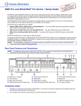
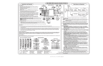
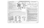
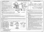
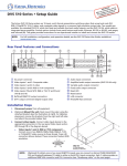
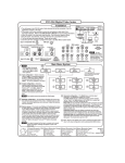
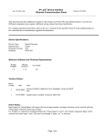
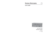
DVS 406
Installation
Installation, cont'd.
7. For unamplified audio output, connect an audio device to the 3.5 mm, 5-pole captive screw connector using the wiring diagram.
Rack mounting
Unbalanced Output
Balanced Output
AUDIO
R
R
Tip
Ring
Sleeve (s)
Tip
Ring
L
L
Tip
See Warning
Sleeve (s)
Tip
See Warning
AUDIO
1. Turn off power to the DVS 406 and all other devices that will be connected.
See example application diagram below right.
2. If the scaler is to be rack or furniture mounted, position the brackets and insert
the mounting screws. For rack mounting, be sure to remove the self-adhesive
rubber feet if they have been attached. See the rack mounting diagram at right.
3. If using Input 1, attach an RGB or HD YUV pass-through signal. The HD YUV
signal will be converted to RGB on the output.
UST
ADJ
HD YUV to / RGB PASS THROUGH
HD YUV to / RGB PASS THROUGH
S 406
DV LER
U
MEN
EO
L VID
NOTE
SCA
ITA
DIG
T
NEX
R
/R-Y
G
/Y
H
/HV
B
/B-Y
R
/R-Y
V
G
/Y
B
/B-Y
V
H
/HV
Connect the sleeve to ground. Connecting the sleeve to a negative (-) terminal will damage the audio output circuits.
TS
EN
TM
JUS
E AD
TUR
RGBS
RGBHV
SIZE
AIL
DET
NT
/CO
E
HD YUV to / RGB PASS THROUGH
SDI
1
EO/
VID O
V S-VIDE
B
/B-Y
H
/HV
V
R
/R-Y
RGsB
G
/Y
EO/
VIDIDEO
S-V
EO/
VIDIDEO
S-V
/YU
H
/HV
B
/B-Y
TAK
5
4
3
2
G
/Y
CEN
PIC
BRT
/TNT
COL
6
HD YUV to / RGB PASS THROUGH
R
/R-Y
8. Plug the DVS 406, and input and output devices into a grounded AC source, and turn on the input and output devices.
9. Use the LCD menu screens (see below) or RS-232 programming to configure the scaler.
TER
RGB
V
Main Menu System
RGB
HDTV Component
Use the MENU and NEXT buttons to navigate through the menu system. Use the Adjust knobs to make configuration changes.
If using Input 2, attach either an RGB pass-through, RGBcvS, YUVp,
or YUVi signal.
Power
on
Application Example
Extron
DVS 406
2 sec.
2 sec.
Input #2
RGB
INPUT
G
/Y
B
/B-Y
H
/HV
R
/R-Y
V
G
/Y
B
/B-Y
H
/HV
RGBHV
H. SHIFT
V
MENU
RGB 109xi
VGA INTERFACE W/ADSP
RGB 109xi
2 - RGB PASS THROUGH / R-Y, B-Y, Y
2 - RGB PASS THROUGH / R-Y, B-Y, Y
ID PIN 4
ID PIN 11
BUFFERED LOCAL
MONITOR OUTPUT
R
/R-Y
RGBS/RGBcS
3
VCR
1
R
/R-Y
G
/Y
H
/HV
B
/B-Y
V
R
/R-Y
2 - RGB PASS THROUGH / R-Y, B-Y, Y
G
/Y
B
/B-Y
H
/HV
V
Component
(R-Y, Y, B-Y)
2
Codec
RS-232
Control
DVS 406
Y
/VID
100-240V
50-60Hz
1 - RGB PASS THROUGH
I
N
T
P
U
T
S
2A MAX
C
R
G
R
/RY
G
/Y
B
3
4
5
6
H
/HV
V
Y
/VID
Y
/VID
Y
/VID
H
/HV
V
C
C
C
L
SDI
B
/B-Y
O
U
T
1
R
L
2
R
L
3
RGB
INPUTS
R
L 4
R
R
G
L
5
R
B
L
6
R
L
V
4
Memory
Presets
MENU
6
Exit
Menu
MENU
NEXT
1 Input configuration – Select RGB or HD YUV pass-through for Input 1, RGB pass-through, RGBcS, YUVp, or YUVi for Input 2,
S-video or composite video for Inputs 3 - 5, or SDI (serial digital interface) for Input 6.
SDI
Video Camera 1
Projector
Plasma Display
R
AUDIO
Tip
Ring
Sleeve (s)
Tip
Ring
L
AUDIO
R
R
Tip
Ring
Sleeve (s)
Tip
Ring
L
L
Tip
Sleeve
AUDIO
Tip
Sleeve
2
Output configuration – Select the required output resolution and refresh rate combination. Select the display's sync format:
RGBHV, RGsB, or RGBS. Select positive or negative sync polarity for the horizontal and vertical sync.
3
Audio configuration – To create a smoother transition when switching from one audio input to another, the audio levels can be
adjusted from -15dB to +9dB. Also, the timing for switching to a different audio input can be adjusted: Start (switches to the next
audio at the beginning of the next video input), Middle (switches to the next audio halfway into the next video input), End
(switches to the next audio at the end of the next video input), or Fade (gradually mutes the current audio halfway between the
switch to the new video input, then gradually increases the next audio input from mute).
4 Memory Presets – The presets save Sizing, Centering, and Blanking information for each input (up to 3 presets per input)
except for the pass-through inputs (Input 1 and RGB on Input 2). Select a preset number in the Save submenu of the input,
then press the NEXT button to save it, or delete a saved preset in the Clear submenu of the input by selecting it, then press the
NEXT button to clear the preset.
To recall an input's saved preset, select the input and press the input button successive times to activate each saved preset for
that input. Each recalled preset will display the message "Input #X Memory Y" where "X" refers to the input (2 to 6) and "Y"
refers to the preset (1 to 3).
600 ohms
Unbalanced Input
Balanced Input
Balanced Input
(high impedance)
(high impedance)
(600 ohms)
5
Advanced Configuration – When selecting the Effect type to transition from Input 1 and another input, a cut will cause an
immediate switch, while a dissolve will cause a gradual fade out and fade in (.2 to 1.0 sec). The Take button initiates the switch.
The Edge smoothing feature can be set On/Off. Edge smoothing softens the edges of a picture by minimizing pixel differences.
The Top and Bottom blanking feature is used to remove noise and other undesired extraneous material, such as closed
captioning, by removing scan lines from the top or bottom of the screen. Up to 127 lines can be removed.
RGB delay allows for glitchless switching between video inputs by switching to the new sync signal before switching to the new
video signal. The video signal delay can be adjusted from 0 to 5 seconds in 0.5 second steps.
The Switch mode feature enables input switching automatically (Auto) when a new input is selected, or only after the Take
button is pressed (Take).
Blue mode can be set On/Off. Setting this mode On will pass only sync and blue signals to the display for setup purposes.
Key mode allows Input 1 and any other input to be displayed simultaneously, one over the other. Key mode must be set On and
the other input must have it's output resolution locked to Input 1. With the second input selected, press the Take button
(Switch mode previously set to "Take"), then press Input 1 twice to initiate the Key mode effect. Press any input button to escape.
Enhanced mode can be set On/Off. Setting this mode On will activate signal gain for increased image sharpness.
Reset will reset the scaler to its factory default values. Press the Take button for about 2 seconds until the LCD confirm prompt
message appears, then press the Take button again.
6
Exit – Return to the default menu cycle by pressing the NEXT button or return to the main menu system by pressing MENU.
5. For display output, connect an output display device to the output BNC connectors.
H/HV
RGBHV
V
R
G
B
RGBS
H/HV
V
R
G
B
H/HV
V
RGsB (Sync on Green)
6. Connect an RGB display device to the 15-pin HD output connector. Using this connector and the output BNCs will allow simultaneous
output.
Extron Electronics, USA Extron Electronics, Europe Extron Electronics, Asia Extron Electronics, Japan
www.extron.com
Output
Configuration
2 - RGB PASS THROUGH / R-Y, B-Y, Y
4. Connect up to six balanced or unbalanced stereo audio input devices to the DVS 406. Each audio input has a 3.5 mm, 5-pole captive
screw connector. The illustrations below indicate how to wire the connectors for the appropriate audio input type and impedance.
600 ohms
B
MENU
MENU
Composite video
G
MENU
RS-232
If using Input 6, connect the SDI signal to the BNC.
R
MENU
OUTPUT
R
H/HV
C
S-video
Advanced
Configuration
PC Computer
If using Inputs 3 to 5, attach an S-video or composite video source.
Y
/VID
Audio
Configuration
Video Camera 2
DVD Player
2 - RGB PASS THROUGH / R-Y, B-Y, Y
RGsB
5
Input
Configuration
1230 South Lewis Street
Anaheim, CA 92805
USA
714.491.1500
Fax 714.491.1517
Beeldschermweg 6C
3821 AH Amersfoort
The Netherlands
+31.33.453.4040
Fax +31.33.453.4050
135 Joo Seng Road, #04-01
PM Industrial Building
Singapore 368363
+65.6383.4400
Fax +65.6383.4664
Daisan DMJ Building 6F
3-9-1 Kudan Minami
Chiyoda-ku, Tokyo 102-0074 Japan
+81.3.3511.7655
33-591-01 B
Fax +81.3.3511.7656
03 02
Printed in the USA