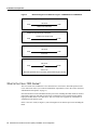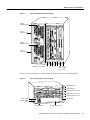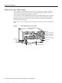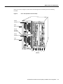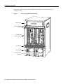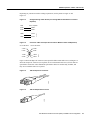
1
Customer Order Number:
Documentation Part Number:
DOC-781812=
78-1812-10
Fast Ethernet Interface Processor (FEIP)
Installation and Configuration
Product Numbers: CX-FEIP-1TX=, CX-FEIP-2TX=, CX-FEIP-1FX=, CX-FEIP-2FX=
This configuration note is a standalone publication that provides instructions for installing and
configuring the Fast Ethernet Interface Processor (FEIP) in all Cisco 7000 series routers and
Cisco 7500 series routers. (For specific compatibility requirements, refer to the section “Software
and Hardware Prerequisites,” on page 3.)
Note For convenience throughout this publication, FEIP-1TX, FEIP-2TX, FEIP-1FX, and
FEIP-2FX are referred to as FEIP, with specific differences clearly noted.
Included in this configuration note are steps for FEIP hardware installation and cable connection,
and basic FEIP configuration steps and examples. A table of contents is included so you can more
easily find what you need.
For additional descriptions of interface subcommands and configuration options available for Fast
Ethernet (FE) interfaces, refer to the appropriate Cisco IOS software configuration and command
reference publications listed in the section “If You Need More Information” on page 2.
Corporate Headquarters
Cisco Systems, Inc.
170 West Tasman Drive
San Jose, CA 95134-1706
USA
Copyright © 1995–2002
Cisco Systems, Inc.
All rights reserved.
1
Document Contents
Document Contents
This publication includes the following sections:
•
•
•
•
•
•
•
If You Need More Information
Installation Prerequisites on page 3
What Is the FEIP?, page 15
FEIP Installation, page 21
Configuring the Fast Ethernet Interfaces* on page 28
Upgrading FEIP Microcode, page 37
Cisco.com on page 41
If You Need More Information
The Cisco IOS software running your router contains extensive features and functionality. For
information on Cisco IOS software and for general installation and maintenance information for
your router, use the following resources:
•
Cisco Documentation CD-ROM package
Cisco documentation and additional literature are available in a CD-ROM package, which ships
with your product. The Documentation CD-ROM, a member of the Cisco Connection Family, is
updated monthly; therefore, it might be more up to date than printed documentation. To order
additional copies of the Documentation CD-ROM, contact your local sales representative or call
customer service. The CD-ROM package is available as a single package or as an annual
subscription.
•
For Cisco IOS software configuration information and support, refer to the modular
configuration and modular command reference publications in the Cisco IOS software
configuration documentation set that corresponds to the software installed on your Cisco
hardware. You can also refer to the Cisco IOS software release notes for the version of software
you are using on your hardware.
•
For hardware installation and maintenance information on the Cisco 7500 series routers, refer to
the Cisco 7500 Series Installation and Configuration Guide that shipped with your Cisco 7500
series router.
•
For hardware installation and maintenance information on the Cisco 7000 series routers, refer to
the Cisco 7000 Hardware Installation and Maintenance manual and the Cisco 7000 User Guide,
or to the Cisco 7010 Hardware Installation and Maintenance manual and the Cisco 7010 User
Guide, which shipped with your Cisco 7000 or Cisco 7010 router, respectively.
Note You can access Cisco IOS software documentation and hardware installation and
maintenance documentation on the World Wide Web at http://www.cisco.com,
http://www-china.cisco.com, http://www-europe.cisco.com.
If you are reading Cisco documentation on the World Wide Web, you can submit comments
electronically. Click Feedback on the toolbar, and then select Documentation. After you complete
the form, click Submit to send it to Cisco. We appreciate your comments.
2 Fast Ethernet Interface Processor (FEIP) Installation and Configuration
Installation Prerequisites
•
To obtain information about documentation, refer to the following:
— World Wide Web on page 40
— Documentation CD-ROM on page 40
— Ordering Documentation on page 40
— Documentation Feedback on page 40
— Cisco.com on page 41
— Technical Assistance Center on page 41
— The Cisco Information Packet that shipped with your router.
Installation Prerequisites
This section provides software and hardware prerequisites, a list of parts and tools you will need to
perform the installation, and safety and ESD-prevention guidelines to help you to avoid injury and
damage to the equipment. It also provides a detailed description of the OIR function to help you
perform online installation successfully and avoid error message and system restarts. If you are
installing a new FEIP, be sure to review the equipment descriptions and distance limitations in the
section “FEIP Receptacles, Cables, and Pinouts” on page 17.
Software and Hardware Prerequisites
The FEIP with 100BASE-TX port adapters operates with the CxBus and CyBus and requires that
the host Cisco 7000 series router is running Cisco IOS Release 10.3(5), or later, and the host
Cisco 7500 series routers are running Cisco IOS Release 10.3(6) or later.
The FEIP with 100BASE-FX port adapters operates with the CxBus and CyBus and requires that
the host Cisco 7000 family router is running Cisco IOS Release 10.3(13), or later, Release 11.0(10),
or later, or Release 11.1(5), or later.
Note The latest FEIP microcode images are available via anonymous File Transfer Protocol (FTP)
from /ftp/feip-fx at ftp.cisco.com. Detailed information about the latest FEIP microcode
images can be found in the ASCII file feip.readme.txt, which is also available via FTP from
ftp.cisco.com in the directory /ftp/feip-fx/. This ASCII file includes information and
instructions on how to get the current FEIP microcode image. To access Cisco IOS images, refer to
the section “Cisco.com” on page 41 at the end of this publication.
Caution If you use the FEIP with a single port adapter, you must have the port adapter in slot 0 for the FEIP
to function properly. A single port adapter in slot 1 will not be recognized by the system.
Note Each FE interface on an FEIP can be configured at 100 Mbps, half duplex or full duplex, for
a maximum aggregate bandwidth of 200 Mbps.
Caution To prevent oversubscribing the FEIP, we recommend that you do not operate both FE interfaces on
an FEIP in full-duplex mode.
Fast Ethernet Interface Processor (FEIP) Installation and Configuration
3
Installation Prerequisites
Each FEIP is a fixed configuration; therefore, individual port adapters are not available as spare parts
and are not field-replaceable or removable. The entire FEIP assembly is treated as a field-replaceable
unit (FRU). Do not attempt to remove an FEIP’s port adapter and replace it with another. Do not
attempt to simultaneously operate 100BASE-TX and 100BASE-FX port adapters on the same FEIP.
List of Parts and Tools
You need the following tools and parts to install or upgrade an FEIP. If you need additional
equipment, contact a service representative for ordering information.
•
CX-FEIP-1TX(=), CX-FEIP-2TX(=), CX-FEIP-1FX(=), or CX-FEIP-2FX(=), and at least one
available interface processor slot in your Cisco 7000 series or Cisco 7500 series router (For
specific compatibility requirements, refer to the section “Software and Hardware Prerequisites”
on page 3.)
•
Cables appropriate for the interfaces on your FEIP; Cisco Systems does not supply Category 5
UTP RJ-45 cables, MII cables, or SC-type cables; these cables are available commercially. (For
specific cable requirements, refer to the section “FEIP Receptacles, Cables, and Pinouts” on
page 17.)
Caution Before you attach an MII transceiver to an MII receptacle on your FEIP, ensure that your MII
transceiver responds to physical sublayer (PHY) address 0 per section 22.2.4.4. “PHY Address” of the IEEE
802.3u specification; otherwise, interface problems might result. Confirm that this capability is available on
your MII transceiver with the transceiver's vendor or in the transceiver's documentation. If a selection for
“Isolation Mode” is available, we recommend you use this setting (if no mention is made of “PHY
addressing”).
Caution To prevent system problems, do not simultaneously connect cables to the RJ-45 (or SC) and MII
receptacles on a single FEIP interface. Each interface (100BASE-FX or 100BASE-TX) can have either an
MII attachment or an RJ-45 (or SC) attachment, but not both. The MII and RJ-45 (or SC) receptacles
represent two physical connection options for one interface.
•
•
Number 1 Phillips and a 3/16-inch, flat-blade screwdriver
Your own ESD-prevention equipment or the disposable grounding wrist strap included with all
upgrade kits, FRUs, and spares
Safety Guidelines
Following are safety guidelines that you should follow when working with any equipment that
connects to electrical power or telephone wiring.
Electrical Equipment Guidelines
Follow these basic guidelines when working with any electrical equipment:
•
Before beginning any procedures requiring access to the chassis interior, locate the emergency
power-off switch for the room in which you are working.
•
•
•
Disconnect all power and external cables before moving a chassis
Do not work alone when potentially hazardous conditions exist.
Never assume that power has been disconnected from a circuit; always check.
4 Fast Ethernet Interface Processor (FEIP) Installation and Configuration
Safety Guidelines
•
•
Do not perform any action that creates a potential hazard or makes the equipment unsafe.
Carefully examine your work area for possible hazards such as moist floors, ungrounded power
extension cables, and missing safety grounds.
Telephone Wiring Guidelines
Use the following guidelines when working with any equipment that is connected to telephone
wiring or to other network cabling:
•
•
Never install telephone wiring during a lightning storm.
•
Never touch uninsulated telephone wires or terminals unless the telephone line has been
disconnected at the network interface.
•
Use caution when installing or modifying telephone lines.
Never install telephone jacks in wet locations unless the jack is specifically designed for wet
locations.
Preventing Electrostatic Discharge Damage
Electrostatic discharge (ESD) damage, which can occur when electronic cards or components are
improperly handled, results in complete or intermittent failures.
Use the following guidelines for preventing ESD damage:
•
•
•
Always use an ESD wrist or ankle strap and ensure that it makes good skin contact.
•
When removing a component, use any available ejector levers or captive installation screws to
release the bus connectors from the backplane or midplane.
•
Handle carriers by available handles or edges only; avoid touching the printed circuit boards or
connectors.
•
Place a removed component board-side-up on an antistatic surface or in a static shielding
container; otherwise, immediately place it in a static shielding container.
•
Avoid contact between the printed circuit boards and clothing. The wrist strap only protects
components from ESD voltages on the body; ESD voltages on clothing can still cause damage.
•
Never attempt to remove the printed circuit board from the metal carrier.
Connect the equipment end of the strap to an unfinished chassis surface.
When installing a component, use any available ejector levers or captive installation screws to
properly seat the bus connectors in the backplane.
Caution For safety, periodically check the resistance value of the antistatic strap. The measurement should
be between 1 and 10 megohms.
Fast Ethernet Interface Processor (FEIP) Installation and Configuration
5
Installation Prerequisites
Guidelines for Interface Processor Installation and Removal
This section describes mechanical functions of system components, emphasizes the importance of
following correct procedures to avoid unnecessary board failures, and is for background only;
specific procedures follow in the section “FEIP Installation” on page 21.
You can remove and replace interface processors while the system is operating; you do not need to
notify the software or reset the system power. This functionality enables you to add, remove, or
replace interface processors with the system online, which provides a method that is seamless to end
users on the network, maintains all routing information, and ensures session preservation.
After an interface processor is reinstalled, the system brings on line only interfaces that match the
current configuration and were previously configured as up; all others require that you configure
them with the configure command.
Caution The system can indicate a hardware failure if you do not follow proper procedures. Remove or
insert only one interface processor at a time. Allow at least 15 seconds for the system to complete the
preceding tasks before removing or inserting another interface processor. Disrupting the sequence before the
system completes its verification can cause the system to interpret hardware failures.
Cisco 7000 series and Cisco 7500 series routers have ejector levers located on the ends of the
interface processor slots. (See Figure 1a.) The function of the ejector levers is to align and seat the
interface processor connectors in the backplane. Failure to use the ejector levers and insert the
interface processor properly can disrupt the order in which connector pins make contact with the
backplane.
Follow the FEIP installation and removal instructions carefully, and review the following examples
of incorrect insertion practices and their results:
•
Using the handle to force the interface processor all the way into the slot can pop the ejector
levers out of their springs. If you then try to use the ejector levers to seat the interface processor,
the first layer of pins (which are already mated to the card or interface processor) can disconnect
and then remate with the backplane, which the system interprets as a board failure.
•
Using the handle to force or slam the interface processor all the way into the slot can damage the
pins on the board connectors if they are not aligned properly with the backplane.
•
When using the handle (rather than the ejector levers) to seat the interface processor in the
backplane, you might need to pull the interface processor back out and push it in again to align
it properly. Even if the backplane pins are not damaged, the pins mating with and disconnecting
from the card or interface processor might cause the system to interpret a board failure. Using the
ejector levers ensures that the board connector mates with the backplane in one continuous
movement.
•
Using the handle to insert or remove an interface processor, or failing to push the ejector levers
fully against the interface processor, can leave some (not all) of the connector pins mated to the
card or interface processor, a state which hangs the system. Using the ejector levers and making
sure that they are pushed fully into position ensures that all three layers of pins are mated with
(or free from) the backplane.
Use the ejector levers when removing an interface processor to ensure that the backplane connector
pins disconnect from the interface processor in the sequence expected by the system. Any interface
processor that is only partially connected to the backplane can hang the bus. Steps for correctly
performing OIR are included with the following procedures for installing and removing the FEIP.
6 Fast Ethernet Interface Processor (FEIP) Installation and Configuration
Guidelines for Interface Processor Installation and Removal
Figure 1
Ejector Levers/Captive Installation Screws on the FEIP (Horizontal
Orientation Shown)
Interface processor
card slot
Ejector
lever
Interface processor card
carrier guide (black)
a
b
Captive
installation
screw
H1984
c
Note The FEIP is oriented horizontally in the Cisco 7010 and Cisco 7505 and vertically in the
Cisco 7000, Cisco 7507, and Cisco 7513.
Fast Ethernet Interface Processor (FEIP) Installation and Configuration
7
Installation Prerequisites
Microcode Overview
The FEIP microcode (firmware) is an image that provides card-specific software instructions. A
programmable read-only memory (PROM) device on the FEIP contains a default microcode boot
image that assists the system in finding and loading the microcode image from the Cisco IOS
software bundle or Flash memory. The router supports downloadable microcode, which allows you
to upgrade microcode versions by downloading new microcode images, storing them in system
Flash memory, and instructing the system to load its image from Flash. You can store multiple
images for an interface type and, with a configuration command, instruct the system to load any one
of them or the default microcode image. The microcode boot image in the PROM initializes the FEIP
and then assists downloading the FEIP microcode image. All interfaces of the same type (FEIP, and
so on) load the same microcode image, either from the microcode image bundled with the Cisco IOS
software or from an image stored in system Flash. Although multiple microcode versions for a
specific interface type can be stored concurrently in Flash, only one image can load at startup.
The show controllers cbus command displays the currently loaded and running microcode version
for each interface processor, and FEIP. The show startup-config EXEC command shows the current
system instructions for loading microcode at startup.
Software and interface processor microcode images are carefully optimized and bundled to work
together. Overriding the bundle can result in system incompatibilities. We recommend that you use
the microcode included in the software bundle. For a complete description of microcode and
downloading procedures, refer to the section “Upgrading FEIP Microcode” on page 37.
Fast Ethernet Overview
The term Ethernet is commonly used for all carrier sense multiple access/collision detection
(CSMA/CD), local-area networks (LANs) that generally conform to Ethernet specifications,
including Fast Ethernet under IEEE 802.3u.
Note 100BASE-TX is intended for Environment A, and 100BASE-FX is intended for
Environment B.
IEEE 802.3u is well suited to applications where a local communication medium must carry
sporadic, occasionally heavy traffic at high peak data rates. Stations on a CSMA/CD LAN can access
the network at any time. Before sending data, the station listens to the network to see if it is already
in use. If it is, the station waits until the network is not in use, then transmits; this is half-duplex
operation.
A collision occurs when two stations listen for network traffic, hear none, and transmit very close to
simultaneously. When this happens, both transmissions are damaged, and the stations must
retransmit. The stations detect the collision and use backoff algorithms to determine when they
should retransmit. Both Ethernet and IEEE 802.3u are broadcast networks, which means that all
stations see all transmissions. Each station must examine received frames to determine if it is the
intended destination and, if it is, to pass the frame to a higher protocol layer for processing.
IEEE 802.3u specifies the following different physical layers for 100BASE-T:
•
100BASE-TX—100BASE-T, half and full duplex over Category 5 unshielded twisted-pair
(UTP), Electronics Industry Association/Telecommunications Industry Association
[EIA/TIA]-568-compliant cable
•
100BASE-FX—100BASE-T, half and full duplex over optical fiber
8 Fast Ethernet Interface Processor (FEIP) Installation and Configuration
IEEE 802.3u 100BaseT Specifications
•
100BASE-T4—100BASE-T, half and full duplex over Category 3, 4, or 5 UTP or shielded
twisted-pair (STP) cabling with four pairs; also called 4T+ or T2, which is 2-pair UTP over
Category 3 cable.
Each physical layer protocol has a name that summarizes its characteristics in the format
speed/signaling method/segment length, where speed is the LAN speed in megabits per second
(Mbps), signaling method is the signaling method used (either baseband or broadband), and segment
length is typically the maximum length between stations in hundreds of meters. Therefore,
100BASE-T specifies a 100-Mbps, baseband LAN with maximum network segments of 100 meters
(or 400 meters for 100BASE-FX).
IEEE 802.3u 100BaseT Specifications
This section provides specifications for IEEE 802.3u 100BaseT. Table 1-1 provides cabling
specifications for 100BaseTX Fast Ethernet transmission over UTP and foil twisted-pair (FTP), and
100BaseFX Fast Ethernet over fiber-optic cables. It also summarizes IEEE 802.3u 100BaseTX and
100BaseFX physical characteristics. Also see Figure 2.
Table 1
Specifications and Connection Limits for 100BASE-TX and 100BASE-FX Transmission
Parameter
100BASE-TX
51
UTP2,
100BASE-FX Single Mode
62.5/125 multimode optical fiber
9/125 micron single-mode optical fiber
Cable specification
Category
Maximum segment
length (half-duplex)3
100 m
412 m
N/A
Maximum segment
length (full-duplex)3
100 m
2000 m
10,000 m
Maximum network
length (half-duplex, one
repeater)4
200 m
272 m
N/A
Data rate
100 Mbps
100 Mbps
100 Mbps
Signaling method
4B/5B block coded, scrambled, with
MLT-3 line coding
4B/5B block coded, with NRZI
line coding
4B/5B block coded, with NRZI line
coding
Connector
SC-type: dual simplex or single
duplex for RX and TX
RJ-45 (ISO/IEC 60603-7:-1990
Single mode SC-type: dual simplex or
single duplex for RX and TX
Topology
Star/hub
Star/hub
Star/hub
1.
2.
3.
4.
22 to 24 AWG
100BASE-FX Multimode
EIA/TIA-568 or EIA-TIA-568 TSB-36 compliant.
Cisco does not supply Category 5 UTP RJ-45 cables. However, they are available commercially.
Data Terminal Equipment (DTE to DTE), see Figure 2.
DTE to Repeater to DTE, see Figure 2.
Fast Ethernet Interface Processor (FEIP) Installation and Configuration
9
Installation Prerequisites
Figure 2
Maximum Segment and Network Lengths—100BASE-FX and 100BASE-TX
Maximum segment length, full duplex
100 m TX
DTE*
DTE
2000 m FX–multimode
Maximum segment length, full duplex
10,000 m FX–single mode
DTE
DTE
Maximum segment length, half duplex
100 m TX
DTE
DTE
412 m FX
Maximum network length, half duplex
DTE
200 m TX
R
(Repeater)
DTE
**Because repeaters have more delay, total network length is shorter.
31703
272 m FX**
*DTE = Data Terminal Equipment
What Is the Cisco 7000 Series?
The Cisco 7000 series includes the Cisco 7000 and Cisco 7010 routers. The FEIP operates in the
Cisco 7000 series routers. (For software and hardware requirements, refer to the section “Software
and Hardware Prerequisites” on page 3.)
Network interfaces reside on modular interface processors, including the FEIP, which are inserted
into interface processor slots and provide a direct connection between external networks and the
high-speed CxBus in the Cisco 7000 series. The Cisco 7000 series supports any combination of
available network interface types.
In the 7-slot Cisco 7000 (see Figure 3), slots 0 through 4 are for interface processors including the
FEIP.
10 Fast Ethernet Interface Processor (FEIP) Installation and Configuration
What Is the Cisco 7000 Series?
Figure 3
Cisco 7000 (Interface Processor End)
Captive
installation screw
DC
AC
FA
IL
PO
WE
EN
R
AB
LE
NO
RM
AL
Upper
power supply
EJ
EC
T
I
SL SLO
OT T
0 1
O
Captive
installation screw
CP
U
EN
AB
HA
LT
LE
RE
SE
T
DC
AC
FA
IL
PO
WE
R
Lower
power supply
AU
NS
OL
E
I
ROUTE SWITCH PROCESSOR
CO
H5288
X.
O
Interface processor slots
1
0
2
3
4
RSP RSP
7000 7000CI
slot 5 slot 6
In the 5-slot Cisco 7010 (Figure 4), slots 0 through 2) are for interface processors including the FEIP.
Figure 4
Cisco 7010 (Interface Processor End)
RSP7000CI slot 4
RSP7000 slot 3
LE
NS
O
CO
AU
X.
HA
LT
RE
SE
T
CP
U
EC
T
Interface processor slot 2
EN
AB
EN
LE
AB
LE
EJ
L
MA
NO
R
SL SLO
OT T
0 1
ROUTE SWITCH PROCESSOR
Interface processor slot 1
Interface processor slot 0
Power switch
H5874
DC OK LED
Chassis ground
screw
Power receptacle
AC-input power supply
Fast Ethernet Interface Processor (FEIP) Installation and Configuration
11
Installation Prerequisites
What Is the Cisco 7500 Series?
The Cisco 7500 series includes the Cisco 7505, Cisco 7507, and Cisco 7513 routers. The FEIP
operates in the Cisco 7500 series routers. (For software and hardware requirements, refer to the
section “Software and Hardware Prerequisites” on page 3.)
Network interfaces reside on modular interface processors, including the FEIP, which are inserted
into interface processor slots and provide a direct connection between external networks and the
high-speed CyBus in the Cisco 7500 series. The Cisco 7500 series supports any combination of
available network interface types.
In the 5-slot Cisco 7505 (see Figure 5), slots 0 through 3 are for interface processors including the
FEIP.
Cisco 7505 (Interface Processor End)
T
E
OL
NS
CO
AU
X.
HA
SE
U
RE
CP
T
EC
Interface processor slot 3
EN
AB
EN
LE
AB
LE
EJ
SL SLO
OT T
0 1
AL
RM
NO
RSP slot
ROUTE SWITCH PROCESSOR
LT
Figure 5
Interface processor slot 2
Interface processor slot 1
Interface processor slot 0
H2761
Power switch
Chassis
grounding
receptacles
Power receptacle
12 Fast Ethernet Interface Processor (FEIP) Installation and Configuration
AC-input power supply
DC OK LED
What Is the Cisco 7500 Series?
In the Cisco 7507 (see Figure 6), slots 0 and 1 and 4 through 6 are for interface processors including
the FEIP.
Figure 6
Cisco 7507 (Interface Processor End)
Captive
installation screw
DC
AC
FA
IL
PO
WE
R
EN
NO
AB
RM
LE
AL
Upper
power supply
Chassis
grounding
receptacles
EJ
EC
T
SL SLO
OT T
0 1
I
SL MA
AV ST
E ER
O
SL
AV
E/M
AS
TE
R
Captive
installation screw
CP
U
HA
LT
EN
AB
RE
LE
SE
T
DC
AC
FA
IL
PO
WE
H3888
R
Lower
power supply
AU
X.
NS
OL
E
I
ROUTE SWITCH PROCESSOR 2
CO
O
Slot 0
1
2
3
4
5
6
RSP slots
Fast Ethernet Interface Processor (FEIP) Installation and Configuration
13
Installation Prerequisites
In the Cisco 7513 (see Figure 7), slots 0 through 5 and 8 through 12 are for interface processors
including the FEIP.
Figure 7
Cisco 7513 (Interface Processor End)
Blower module
Cable-management
bracket
NO
RM
AL
EN
AB
LE
EJE
CT
SLO SLO
T0 T1
SLA MAS
VE TE
R
Card cage and
processor modules
SLA
VE
/M
AS
TE
R
CP
U
HA
LT
RE
SE
EN
T
AB
LE
AU
X.
ROUTE SWITCH PROCESSOR 2
CO
NS
OLE
Air intake vent
AC
OK
FAN
OK
OUTPUT
FAIL
AC
OK
OUTPUT
FAIL
POWER
A
POWER
B
Chassis grounding
receptacles
I
I
0
0
14 Fast Ethernet Interface Processor (FEIP) Installation and Configuration
H5268
Power supplies
FAN
OK
What Is the FEIP?
What Is the FEIP?
The FEIP provides up to two 100-Mbps, IEEE 802.3u Fast Ethernet interfaces. (Figure 8 shows a
two-port 100BASE-TX FEIP.)
The FEIP is available in the following fixed configurations:
•
•
•
•
CX-FEIP-1TX(=)—FEIP with one 100BASE-TX port adapter in port adapter slot 0
CX-FEIP-2TX(=)—FEIP with two 100BASE-TX port adapters
CX-FEIP-1FX(=)—FEIP with one 100BASE-FX port adapter in port adapter slot 0
CX-FEIP-2FX(=)—FEIP with two 100BASE-FX port adapters
Figure 8
Fast Ethernet Interface Processor (FEIP-2TX)
Bus connector
Microcode
ROM U37
H2940
DRAM
SIMMs
MII
RJ-45
Each 100BASE-TX interface has an RJ-45 connector to attach to Category 5 unshielded twisted-pair
(UTP) for 100BASE-TX, and an MII connector that permits connection through external
transceivers to multimode fiber for 100BASE-FX, or to Category 3, 4, and 5 UTP or shielded
twisted-pair (STP) for 100BASE-T4 physical media. Each 100BASE-TX or 100BASE-FX interface
on an FEIP can be configured at 100 Mbps, half duplex or full duplex, for a maximum aggregate
bandwidth of 200 Mbps.
Caution To prevent oversubscribing the FEIP, we recommend that you do not operate both FE interfaces on
an FEIP in full-duplex mode.
For pinouts, refer to the section “FEIP Receptacles, Cables, and Pinouts” on page 17. The standard
dynamic random access memory (DRAM) size for the FEIP is 8 megabytes (MB). You can install
FEIPs in any available interface processor slots.
Fast Ethernet Interface Processor (FEIP) Installation and Configuration
15
What Is the FEIP?
Note Each FEIP is a fixed configuration; therefore, individual port adapters are not available as
spare parts and are not field-replaceable or removable. The entire FEIP card is treated as a
field-replaceable unit (FRU). Do not attempt to remove an FEIP’s port adapter and replace it with
another. Do not attempt to install 100BASE-TX and 100BASE-FX port adapters on the same FEIP.
Caution To prevent system problems, we recommend that you not attempt to remove an FEIP port adapter
and replace it with another, nor attempt to mix 100BASE-TX and 100BASE-FX FE port adapters on the same
FEIP.
Note Each of the two 100BASE-FX interfaces on the FEIP-2FX uses the MII connector like the
FEIP-2TX, but the FEIP-2FX has an SC-type fiber-optic connector in place of the RJ-45 connector.
Either the MII LED or the RJ-45 (or FIBER) LED should be on at any one time; never both.
Caution To prevent system problems, do not simultaneously connect cables to the RJ-45 (or SC) and MII
receptacles on a single FEIP port adapter. Each port adapter (100BASE-FX or 100BASE-TX) can have either
an MII attachment or an RJ-45 (or SC) attachment, but not both. The MII and RJ-45 (or SC) receptacles
represent two physical connection options for one port adapter.
FEIP LEDs
The FEIP contains the enabled LED and a bank of three status LEDs for each of the two port adapters
(located between the two receptacles on each port adapter). After system initialization, the enabled
LED goes on to indicate that the FEIP has been enabled for operation. (The LEDs are shown in
Figure 9.)
LEDs on an FEIP Port Adapter (Partial Faceplate View)
H2941
Figure 9
The following conditions must be met before the enabled LED goes on:
•
•
•
The FEIP is correctly connected and receiving power
The FEIP card contains a valid microcode version that has been downloaded successfully
The bus recognizes the FEIP.
If any of these conditions is not met, or if the initialization fails for other reasons, the enabled LED
does not go on.
16 Fast Ethernet Interface Processor (FEIP) Installation and Configuration
FEIP Receptacles, Cables, and Pinouts
Following are the three status LEDs and an explanation of what each indicates:
•
•
MII—On when the MII port is selected as the active port by the controller.
•
RJ45 (or FIBER on FEIP-1FX or FEIP-2FX)—On when the RJ-45 (or FIBER) port is selected
as the active port by the controller.
Link—When the RJ-45 or SC port is active, this LED is on when the port adapter is receiving a
carrier signal from the network. When the MII port is active, this LED is an indication of network
activity, and it flickers on and off proportionally to this activity.
FEIP Receptacles, Cables, and Pinouts
The two interface receptacles on the FEIP port adapter are a single MII, 40-pin, D-shell type
receptacle, and a single RJ-45 receptacle (or SC-type for FEIP-1FX and -2FX optical-fiber
connections). (See the 1FE-TX port adapter in Figure 10 and the 1FE-FX port adapter in Figure 11.)
You can use either one receptacle or the other; only one receptacle can be used at one time. Each
connection supports IEEE 802.3u interfaces compliant with the 100BASE-X and 100BASE-T
standards. The RJ-45 connection does not require an external transceiver. The MII connection
requires an external physical sublayer (PHY) and an external transceiver. Cisco Systems does not
supply Category 5 UTP RJ-45 cables; these cables are available commercially.
Caution To prevent system problems, do not simultaneously connect cables to the RJ-45 (or SC) and MII
receptacles on a single port adapter. Each port adapter (100BASE-FX or 100BASE-TX) can have either an
MII attachment or an RJ-45 (or SC) attachment, but not both. The MII and RJ-45 (or SC) receptacles
represent two physical connection options for one Fast Ethernet interface.
1FE-TX Port Adapter (Faceplate View)
FAST ETHERNET
45
0
H4495
RJ
I
NK
MI
LI
EN
AB
LE
D
1FE-FX Port Adapter (Faceplate View)
0
TX
RX
BE
R
FAST ETHERNET
FI
NK
LI
MI
I
EN
AB
LE
D
Figure 11
H6014
Figure 10
Fast Ethernet Interface Processor (FEIP) Installation and Configuration
17
What Is the FEIP?
The RJ-45 connection does not require an external transceiver. The MII connection requires an
external physical sublayer (PHY) and an external transceiver. Figure 12 shows the RJ-45 cable
connectors. RJ-45 cables are not available from Cisco Systems, but are available from commercial
cable vendors. Table 2 lists the pinouts and signals for the RJ-45 connectors.
RJ-45 Connections (Connector and Plug)
H2936
Figure 12
87654321
RJ-45 connector
Warning The ports labeled “Ethernet,” “10BASE-T,” “Token Ring,” “Console,” and “AUX” are safety
extra-low voltage (SELV) circuits. SELV circuits should only be connected to other SELV circuits. Because
the BRI circuits are treated like telephone-network voltage, avoid connecting the SELV circuit to the
telephone network voltage (TNV) circuits.
Table 2
RJ-45 Connector Pinout
Pin
Description
1
Receive Data + (RxD+)
2
RxD–
3
Transmit Data + (TxD+)
6
TxD–
Note Referring to the RJ-45 pinout in Table 2, proper common-mode line terminations should be
used for the unused Category 5, UTP cable pairs 4/5 and 7/8. Common-mode termination reduces
the contributions to electromagnetic interference (EMI) and susceptibility to common-mode
sources. Wire pairs 4/5 and 7/8 are actively terminated in the RJ-45, 100BASE-TX port circuitry in
the FEIP port adapter.
18 Fast Ethernet Interface Processor (FEIP) Installation and Configuration
FEIP Receptacles, Cables, and Pinouts
Depending on your RJ-45 interface cabling requirements, use the pinouts in Figure 13 and
Figure 14.
Straight-Through Cable Pinout (Connecting FEIP RJ-45 Interface to a Hub or
Repeater)
Hub or repeater
5 TxD+
5 RxD+
6 TxD–
6 RxD–
3 RxD+
3 TxD+
4 RxD–
4 TxD–
Figure 14
ub or LAN switch
H3137
FEIP
Crossover Cable Pinout (RJ-45 Connections Between Hubs and Repeaters)
Hub or LAN switch
3 TxD+
3 TxD+
6 TxD–
6 TxD–
1 RxD+
1 RxD+
2 RxD–
2 RxD–
H3138
Figure 13
Figure 15 shows the duplex SC connector (one required for both transmit and receive), and Figure 16
shows the simplex SC connector (two required, one for each transmit and receive) used for 1FE-FX
optical-fiber connections. These multimode optical-fiber cables are commercially available, and
they are not available from Cisco Systems.
1FE-FX Duplex SC Connector
Figure 16
1FE-FX Simplex SC Connector
H2399
H2214
Figure 15
Fast Ethernet Interface Processor (FEIP) Installation and Configuration
19
What Is the FEIP?
Depending on the type of media you use between the MII connection on the port adapter and your
switch or hub, the network side of your 100BASE-T transceiver should be appropriately equipped
with SC-type or ST-type connectors (for optical fiber), BNC connectors, and so forth. Figure 17
shows the pin orientation of the female MII connector on the port adapter.
The MII receptacle uses 2-56 screw-type locks, called jackscrews (shown in Figure 17), to secure
the cable or transceiver to the MII port. MII cables and transceivers have knurled thumbscrews
(screws you can tighten with your fingers) that you fasten to the jackscrews on the FEIP MII
connector. Use the jackscrews to provide strain relief for your MII cable. (The RJ-45 modular plug
has strain relief functionality incorporated into the design of its standard plastic connector.)
Figure 17 shows the MII connector.
Figure 17
MII Connection (Female)
H2943
Pin 21
Jackscrew
Pin 1
Table 3 lists the MII connector pinout and signals. MII cables are available commercially.
Table 3
MII Connector Pinout
Pin1
In
Out
In/Out
Description
14–17
–
Yes
–
Transmit Data (TxD)
12
Yes
–
–
Transmit Clock (Tx_CLK)2
11
–
Yes
–
Transmit Error (Tx_ER)
13
–
Yes
–
Transmit Enable (Tx_EN)
3
–
Yes
–
MII Data Clock (MDC)
4–7
Yes
–
–
Receive Data (RxD)
9
Yes
–
–
Receive Clock (Rx_CLK)
10
Yes
–
–
Receive Error (Rx_ER)
8
Yes
–
–
Receive Data Valid (Rx_DV)
18
Yes
–
–
Collision (COL)
19
Yes
–
–
Carrier Sense (CRS)
2
–
–
Yes
MII Data Input/Output (MDIO)
22–39
–
–
–
Common (ground)
1, 20, 21, 40
–
–
–
+5.0 volts (V)
1. Any pins not indicated are not used.
2. Tx_CLK and Rx_CLK are generated by the external transceiver.
20 Fast Ethernet Interface Processor (FEIP) Installation and Configuration
FEIP Installation
FEIP Installation
The following sections describe the procedures for removing or installing an FEIP in the Cisco 7000
series or Cisco 7500 series routers. The functionality is the same for each router model; therefore,
the term the chassis is used except where specific model issues arise.
The online insertion and removal function allows you to install and remove an FEIP without first
shutting down the system; however, you must follow the instructions carefully. Failure to insert the
FEIP properly can cause system error messages indicating a board failure. For a complete
description of recommended guidelines for interface processor installation and removal, refer to the
section “Guidelines for Interface Processor Installation and Removal” on page 6.
Each unused interface processor slot must contain an interface processor filler (which is an interface
processor carrier without an interface board) to keep dust out of the chassis and to maintain proper
air flow through the interface processor compartment. If you are installing a new FEIP that is not a
replacement, you must first remove the interface processor filler from an unused slot; to do so
proceed to the next section “Removing an Interface Processor or Interface Processor Filler.” If you
are replacing an FEIP, proceed to the section “Removing an FEIP.”
Note To ensure compliance with EMI approvals by providing a tight EMI-preventive seal for the
Cisco 7507 and Cisco 7513 routers, we recommend that you first install interface processors in the
interface processor slots closest to the RSP slots, whenever possible, then work out to the interface
processor slots furthest from the RSP slots. (See Figure 6, on page 13, for the Cisco 7507; see
Figure 7, on page 14, for the Cisco 7513.)
Removing an Interface Processor or Interface Processor Filler
If you plan to replace a currently installed interface processor with an FEIP, attach an
ESD-preventive wrist strap between you and any unpainted chassis surface; interface processor
fillers do not require protection from ESD. Select an interface processor slot for the new FEIP and
remove the interface processor or interface processor filler as follows:
Step 1
Use a screwdriver to loosen the captive installation screws on the interface processor or
interface processor filler. (See Figure 1.)
Step 2
Place your thumbs on both ejector levers and simultaneously pull them both outward to
release the filler from the backplane connector (in the opposite direction from that shown
in Figure 1c).
Step 3
Grasp the handle with one hand and pull the card straight out of the slot, keeping your
other hand under the carrier to guide it. (See Figure 18.) Keep the carrier parallel to the
backplane.
Step 4
Store the interface processor or interface processor filler for future use.
To help prevent dust and contaminants from entering the chassis, do not leave the interface processor
slot open. Immediately proceed to the section “Installing an FEIP” on page 23.
Fast Ethernet Interface Processor (FEIP) Installation and Configuration
21
FEIP Installation
Removing an FEIP
You need not shut down the interface or the system power when removing an FEIP or interface
processor.
Note In Cisco 7507 or Cisco 7513 systems, online insertion and removal of any interface processor
in either CyBus might cause the slave RSP2 to reboot with a bus error or a processor memory parity
error. The master RSP will recover from this event and issue a “cBus Complex Restart” message.
Cisco 7507 and Cisco 7513 systems that are configured with an RSP4 as the system slave are not
affected and will not experience this problem.
If you have a Cisco 7507 or a Cisco 7513 with an RSP2 configured as the system slave, we strongly
recommend that you use the following procedure to remove and replace an interface processor:
Step 1
Remove the slave RSP2.
Step 2
Wait 15 seconds.
Step 3
Remove and replace the interface processor using the procedures in this publication.
Step 4
Wait 15 seconds.
Step 5
Reinsert the slave RSP2.
If you are replacing a failed FEIP, remove the existing board first, then install the new FEIP in the
same slot. If you are replacing a currently installed interface processor with an FEIP, remove the
existing board first, then install the new FEIP in the same slot.
Figure 18 shows proper handling of an interface processor during installation.
Handling Processor Modules for Installation and Removal (Horizontal
Orientation Shown)
H4714
Figure 18
Captive installation
screws
22 Fast Ethernet Interface Processor (FEIP) Installation and Configuration
Installing an FEIP
To remove an FEIP or interface processor, follow these steps:
Step 1
Attach an ESD-preventive wrist strap between you and any unpainted chassis surface.
Step 2
If you are replacing a failed FEIP, disconnect all cables from the FEIP ports; however, if
you are only moving an FEIP to another slot, this step is not necessary.
Step 3
Use a screwdriver to loosen the captive installation screws at both ends of the board.
(See Figure 1.)
Caution Always use the ejector levers to remove or install the FEIP. Failure to do so can cause erroneous
system error messages indicating a board failure.
Step 4
Place your thumbs on the ejector levers and simultaneously pull both of the ejectors
outward (in the opposite direction from that show in Figure 1c) to release the FEIP from
the backplane connector.
Step 5
Use the board’s handle to carefully pull it straight out of the slot, keeping your other hand
under the carrier to guide it. (See Figure 18.) Keep the board parallel to the backplane.
Step 6
Place the removed board on an antistatic mat or foam pad, or place it in an antistatic
container if you plan to return it to the factory.
Step 7
If the interface processor slot is to remain empty, install a filler (MAS7K-BLANK) to
keep dust out of the chassis and to maintain proper air flow inside the chassis. Do not
leave the interface processor slot open. Immediately proceed to the section “Installing an
FEIP.”
Installing an FEIP
The FEIP slides into the open interface processor slot and connects directly to the backplane. The
interface processors are keyed to guide pins on the backplane, so the FEIP can be installed only in
an interface processor slot.
Note To ensure compliance with EMI approvals by providing a tight EMI seal for the Cisco 7507
and Cisco 7513 routers, we recommend that you first install interface processors in the interface
processor slots closest to the RSP slots, whenever possible, then work out to the interface processor
slots furthest from the RSP slots.
Figure 1 shows the functional details of inserting an interface processor and using the ejector levers.
Figure 18 shows proper handling of an interface processor during installation.
Caution Remove or insert only one interface processor at a time. Allow at least 15 seconds for the system
to complete its discovery and initialization before removing or inserting another interface processor.
Disrupting the sequence before the system has completed verification can cause the system to interpret
hardware failures.
Follow these steps to install an FEIP:
Step 1
Ensure that a console terminal is connected to the console port (on the RP, RSP, or
RSP7000) and that your console is turned ON.
Fast Ethernet Interface Processor (FEIP) Installation and Configuration
23
FEIP Installation
Step 2
Hold the FEIP handle with one hand and place your other hand under the carrier to
support the FEIP and guide it into the slot. (See Figure 18.) Avoid touching the card or
any connector pins.
Caution To prevent ESD damage, handle interface processors by the handles and carrier edges only.
Note The processor modules are oriented horizontally in the Cisco 7010 and Cisco 7505 and
vertically in the Cisco 7000, Cisco 7507, and the Cisco 7513.
Step 3
Place the back of the FEIP in the slot and align the notch on the carrier with the groove
in the slot. (See Figure 1.)
Step 4
While keeping the FEIP parallel to the backplane, carefully slide it into the slot until the
back of the faceplate makes contact with the ejector levers, then stop. (See Figure 1b.)
Caution Always use the ejector levers when installing or removing processor modules. A module that is
partially seated in the backplane might cause the system to hang and subsequently crash, and shoving or
slamming the interface processor into the slot can damage the backplane pins and board.
Step 5
Using your thumbs, simultaneously push both ejector levers inward until the FEIP is
pushed entirely into its slot. (See Figure 1c.)
Step 6
Tighten both of the captive installation screws.
Caution To ensure proper electromagnetic interference (EMI) isolation for the chassis, make certain to
tighten the captive installation screws on each FEIP immediately after you install it and before proceeding
with the installation of each remaining FEIP or other interface processor.
Attaching Fast Ethernet Interface Cables
The MII and RJ-45 (or SC) receptacles represent two physical connection options for one port
adapter. Each FEIP has one or two port adapters. On a single port adapter, you can use either the
RJ-45 (or SC for FEIP-1FX or -2FX) connection or the MII connection. You can use the RJ-45 (or
SC for FEIP-1FX or -2FX) connection on one port adapter and the MII connection on the other.
Note RJ-45, SC, and MII cables are not available from Cisco Systems; they are available from
outside commercial cable vendors.
24 Fast Ethernet Interface Processor (FEIP) Installation and Configuration
Attaching Fast Ethernet Interface Cables
Connect RJ-45, SC (FEIP-1FX or -2FX), or MII cables as follows:
If you have MII connections, attach an MII cable directly to the MII port on the FEIP or
attach a 100BASE-T transceiver, with the media appropriate to your application, to the
MII port on the FEIP. (See Figure 19 for FEIP-2TX or Figure 20 for FEIP-2FX.)
Step 1
Caution Before you attach an MII transceiver to an MII receptacle on your FEIP, ensure that your MII
transceiver responds to physical sublayer (PHY) address 0 per section 22.2.4.4. “PHY Address” of the IEEE
802.3u specification; otherwise, interface problems might result. Confirm that this capability is available on
your MII transceiver with the transceiver's vendor or in the transceiver's documentation. If a selection for
“Isolation Mode” is available, we recommend you use this setting (if no mention is made of “PHY
addressing”).
If you have RJ-45 connections, attach the Category 5 UTP cable directly to one of the
RJ-45 ports on the FEIP. (See Figure 19 for FEIP-2TX or Figure 20 for FEIP-2FX.) The
FEIP is an end station device and not a repeater. You must connect the port adapter to a
repeater or hub.
If you have an SC connection (FEIP-1FX or -2FX), attach a cable directly to the SC port
on one of the port adapters. (See Figure 20.) Use either one duplex SC connector, or two
simplex SC connectors, and observe the correct relationship between the receive (RX)
and transmit (TX) ports on the port adapter and your repeater.
Connecting MII or RJ-45 Cables (FEIP-2TX Shown, Horizontal Orientation)
MII cable
To transceiver,
repeater, or DTE
0
FAST ETHERNET
0
FAST ETHERNET
or
H9784
Figure 19
RJ-45 cable
To repeater
or DTE
Note Each Fast Ethernet interface (100BASE-FX or 100BASE-TX) can have either an MII
attachment or an RJ-45 (or SC) attachment, but not both. The MII and RJ-45 (or SC) receptacles
represent two physical connection options for one port adapter.
Fast Ethernet Interface Processor (FEIP) Installation and Configuration
25
FEIP Installation
MII cable
ER
H9785
K
II
FIB
M
LIN
ER
FAST ETHERNET
0
II
M
FAST ETHERNET
0
LIN
K
Connecting MII or SC Cables (FEIP-2FX Shown, Horizontal Orientation)
FIB
Figure 20
or
Simplex (2)
To repeater
To transceiver,
repeater, or DTE
Step 2
Duplex (1)
To repeater
For the 100BASE-TX RJ-45 connections, attach the ferrite bead to the RJ-45 cable (at
either end), as shown in Figure 21.
Caution The ferrite bead prevents electromagnetic interference (EMI) from affecting the
100BASE-TX-equipped system and is a required component for proper system operation.
Attaching the Ferrite Bead around the RJ-45 Cable
Ferrite bead
RJ-45 cable
with ferrite bead
H4202
Figure 21
Caution To prevent problems on your FEIP and network, do not simultaneously connect RJ-45 (or SC) and
MII cables to one port adapter. On a single port adapter, only one network connection can be used at one time.
Only connect cables that comply with EIA/TIA-568 standards. (Refer to Table 1 for cable recommendations
and specifications.)
Step 3
Attach the network end of your RJ-45 (or SC) or MII cable to your 100BASE-T
transceiver, switch, hub, repeater, DTE, or other external 100BASE-T equipment.
Step 4
Repeat Steps 1 through 3 for the second port adapter as required.
This completes the FEIP cable installation.
26 Fast Ethernet Interface Processor (FEIP) Installation and Configuration
Using LEDs to Check FEIP Status
Using LEDs to Check FEIP Status
The FEIP has four status LEDs on its faceplate that indicate status on each FE port. (See Figure 9.)
LEDs (Partial Faceplate View of FEIP)
H2941
Figure 22
After you connect cables, observe the LED states and the console display as the router initializes.
When the system has reinitialized all interfaces, the enabled LED on the FEIP should go on. (For
complete descriptions of the FEIP LEDs, refer to the section “FEIP LEDs” on page 16.)
The console screen will also display a message as the system discovers each interface during its
reinitialization. After system initialization, the enabled LED goes on to indicate that the FEIP is
enabled for operation.
The following conditions must be met before the FEIP is enabled:
•
•
•
The interface processor is correctly connected to the backplane and receiving power.
The system bus recognizes the interface processor.
A valid version of microcode is loaded and running.
If any of these conditions is not met, the enabled LED does not go on.
Verify that the FEIP is connected correctly as follows:
Step 1
While the system reinitializes each interface, observe the console display messages and
verify that the system discovers the FEIP. The system should recognize the FEIP’s
interfaces but leaves them configured as down.
Step 2
When the reinitialization is complete, verify that the enabled LED on each FEIP port
adapter is on and remains on. If the LED does stay on, proceed to Step 5. If the enabled
LED does not stay on, proceed to the next step.
Step 3
If an enabled LED fails to go on, suspect the that the FEIP board connector is not fully
seated in the backplane. Loosen the captive installation screws, then firmly push the top
ejector down while pushing the bottom ejector up until both are parallel to the FEIP
faceplate. Tighten the captive installation screws. After the system reinitializes the
interfaces, the enabled LED on the FEIP should go on. If the enabled LED goes on,
proceed to Step 5. If the enabled LED does not go on, proceed to the next step.
Fast Ethernet Interface Processor (FEIP) Installation and Configuration
27
Configuring the Fast Ethernet Interfaces*
Step 4
If an enabled LED still fails to go on, remove the FEIP and try installing it in another
available interface processor slot.
If the enabled LED goes on when the FEIP is installed in the new slot, suspect a failed
backplane port in the original interface processor slot.
If the enabled LED still fails to go on, but other LEDs on the FEIP go on to indicate
activity, proceed to Step 5 to resume the installation checkout and suspect that the enabled
LED on the FEIP has failed.
If no LEDs on the FEIP go on, suspect that the FEIP is faulty.
If the enabled LED still does not go on, do not proceed with the installation. Contact a
service representative to report the faulty equipment and obtain further instructions.
Step 5
Use the show interfaces or show controllers cbus command to verify the status of the
FEIP’s interfaces. (If the interfaces are not configured, you must configure them using the
procedures in the section “Configuring the Fast Ethernet Interfaces*.”)
If an error message displays on the console terminal, refer to the appropriate reference publication
for error message definitions. If you experience other problems that you are unable to solve, contact
a service representative for assistance.
Configuring the Fast Ethernet Interfaces*
If you installed a new FEIP or if you want to change the configuration of an existing interface, you
must enter configuration mode using the configuration command. If you replaced an interface that
was previously configured, the system recognizes the new interface and bring it up in its existing
configuration.
After you verify that the new FEIP is installed correctly (the enabled LED on each port adapter goes
on), use the privileged-level configure command to configure the new interfaces. Be prepared with
the information you need, such as the following:
•
•
•
Protocols you plan to route on each new interface
Internet protocol (IP) addresses if you plan to configure the interfaces for IP routing
Whether the new interfaces will use bridging
For a summary of the configuration options available and instructions for configuring the interfaces
on the FEIP, refer to the appropriate configuration publications listed in the section “If You Need
More Information” on page 2.
The configure command requires privileged-level access to the EXEC command interpreter, which
usually requires a password. Contact your system administrator if necessary to obtain EXEC-level
access.
Each 100BASE-TX or 100BASE-FX interface on an FEIP can be configured at 100 Mbps, half
duplex or full duplex, for a maximum aggregate bandwidth of 200 Mbps.
Caution To prevent oversubscribing the FEIP, we recommend that you do not operate both interfaces on an
FEIP in full-duplex mode.
28 Fast Ethernet Interface Processor (FEIP) Installation and Configuration
Selecting Interface Processor Slot, Interface, and Interface Port Numbers
Selecting Interface Processor Slot, Interface, and Interface Port Numbers
This section describes how to identify interface processor slot, interface, and interface port numbers.
Although the interface processor slots in the Cisco 7000, Cisco 7507, and Cisco 7513 are vertically
oriented and those in the Cisco 7010 and Cisco 7505 are horizontally oriented, all models use the
same method for slot and port numbering.
In the router, physical port addresses specify the actual physical location of each interface port on
the router interface processor end. (See the example of an FEIP-2TX shown in Figure 23.) This
address is composed of a three-part number in the format interface processor slot number/adapter
number/interface port number.
•
The first number identifies the chassis interface processor slot in which the FEIP is installed (as
shown in the example system in Figure 23).
•
The second number identifies the physical interface on the FEIP and is slot 0 (on the left) and slot
1 (on the right).
•
The third number identifies the interface port, which is always numbered as interface 0.
Interface ports on the FEIP maintain the same address regardless of whether other interface
processors are installed or removed. However, when you move an FEIP to a different slot, the first
number in the address changes to reflect the new interface processor slot number.
Figure 23 shows the interface processor slots and interface ports of a sample Cisco 7505 system. On
the FEIP-2TX, the first interface number is 0 and the second is 1. For example, on the FEIP in slot 3
(shown in Figure 23), the address of the left (first) interface is 3/0/0 (interface processor slot 3,
interface 0, and interface port 0). The address of the right (second) interface is 3/1/0 (interface
processor slot 3, interface 1, and interface port 0).
If you remove the FEIP-2TX from slot 3 and install it in interface processor slot 2, the addresses of
these interfaces become 2/0/0 and 2/1/0.
Interface Port Address Example (Cisco 7505 with FEIP-2TX Shown)
Port address 3/1/0
(100Base-TX interface)
ROUTE SWITCH PROCESSOR
E
OL
CO
AU
X.
U
CP
RE
SE
T
Slot 3
AB
EN
EN
AB
LE
LE
EJ
EC
SL SLO
OT T
0 1
NO
RM
AL
T
HA
LT
Port address 3/0/0
(100Base-TX interface)
NS
Figure 23
Slot 2
Slot 1
Interface
processor
slots
H9786
Slot 0
Note: The MII and RJ-45 interface ports on each port adapter
are both numbered as interface port 0. Only one of them can
be used on each port adapter, at one time.
You can identify interface ports by physically checking the slot/adapter/interface port location on the
back of the router or by using software commands to display information about a specific interface
or all interfaces in the router.
Fast Ethernet Interface Processor (FEIP) Installation and Configuration
29
Configuring the Fast Ethernet Interfaces*
Configuring Interfaces—Descriptions and Examples
This section describes a basic configuration. Press the Return key after each step unless otherwise
noted. At any time you can exit the privileged level and return to the user level by entering disable
at the prompt as follows:
Router# disable
Router>
Following is a basic configuration procedure:
Step 1
At the privileged-level prompt, enter configuration mode and specify that the console
terminal is the source of the configuration subcommands, as follows:
Router# configure terminal
Enter configuration commands, one per line. End with CNTL/Z.
Router(config)#
Step 2
At the prompt, specify the first interface to configure by entering the subcommand
interface, followed by the type (fastethernet) and slot/port (interface processor slot
number/0). The example that follows is for the interface port of the first interface port, on
an FEIP in interface processor slot 1:
Router(config)# interface fa 1/0/0
Step 3
If IP routing is enabled on the system, you can assign an IP address and subnet mask to
the interface with the ip address configuration subcommand, as in the following
example:
Router(config-int)# ip address 1.1.1.10 255.255.255.0
Step 4
Add any additional configuration subcommands required to enable routing protocols and
set the interface characteristics.
Step 5
Change the shutdown state to up and enable the interface as follows:
Router(config-int)# no shutdown
Step 6
Configure additional interfaces as required.
Step 7
When you have included all of the configuration subcommands to complete the
configuration, press Ctrl-Z to exit configuration mode.
Step 8
Write the new configuration to nonvolatile memory as follows:
Router# copy running-config startup-config
[OK]
Router#
Following are descriptions and examples of the commands for configuring interface 3/0/0.
Descriptions are limited to fields that are relevant for establishing and verifying the configuration.
After configuring the new interface, use show commands to display the status of the new interface
or all interfaces, or to verify changes you have made.
Depending on the requirements for your system configuration and the protocols you plan to route on
the interface, you might also need to enter other configuration subcommands. For complete
descriptions of configuration subcommands and the configuration options available for interfaces,
refer to the publications listed in the section “If You Need More Information” on page 2.
30 Fast Ethernet Interface Processor (FEIP) Installation and Configuration
Configuring Interfaces—Descriptions and Examples
FE half-duplex operation is the default. To change to full-duplex operation, use the following series
of commands:
Router# configure terminal
Enter configuration commands, one per line. End with CNTL/Z.
Router(config)#
Router(config)# interface fastethernet 3/0/0
Router(config-if)# full-duplex
Ctrl-z
Note Each 100BASE-TX or 100BASE-FX interface on an FEIP can be configured at 100 Mbps,
half duplex or full duplex, for a maximum aggregate bandwidth of 200 Mbps.
Caution To prevent oversubscribing the FEIP, we recommend that you do not operate both FE interfaces on
an FEIP in full-duplex mode.
Using the show interfaces fastethernet command, you can see that the 3/0/0 interface is now
configured for full-duplex operation:
Router# sh int fa 3/0/0
FastEthernet 3/0/0 is administratively up, line protocol is up
(display text omitted)
Encapsulation ARPA, loopback not set, keepalive not set, fdx, 100BaseTX
To return the interface to half-duplex operation, use the no full-duplex configuration command as
follows:
Router# config t
Enter configuration commands, one per line. End with CNTL/Z.
Router(config)# int fa 3/0/0
Router(config-if)# no full-duplex
Ctrl-z
Router#
Using the show interfaces fastethernet command, you can see that the 3/0/0 interface is now
configured for half-duplex operation:
Router# sh int fa 3/0/0
FastEthernet3/0/0 is administratively up, line protocol is up
(display text omitted)
Encapsulation ARPA, loopback not set, keepalive not set, hdx, 100BaseTX
(display text omitted)
Fast Ethernet Interface Processor (FEIP) Installation and Configuration
31
Configuring the Fast Ethernet Interfaces*
The RJ-45 connection is the default for FEIP-2TX (or SC for FEIP-2FX). To change to an MII
connection and then verify it, use the following series of commands, including the media-type
configuration command:
Router# config t
Enter configuration commands, one per line. End with CNTL/Z.
Router(config)# int fa 3/0/0
Router(config-if)# media-type mii
Ctrl-z
Router#
Router# sh int fa 3/0/0
FastEthernet3/0/0 is administratively up, line protocol is up
(display text omitted)
Encapsulation ARPA, loopback not set, keepalive not set, hdx, MII
(display text omitted)
Use the media-type 100 configuration command to return the interface to its default state for RJ-45
or SC (fiber-optic) connections.
Checking the Configuration
After configuring the new interface, use the show commands to display the status of the new
interface or all interfaces, and use the ping command to check connectivity.
Using show Commands to Verify the FEIP Status
The following steps use show commands to verify that the new interfaces are configured and
operating correctly.
Step 1
Use the show version command to display the system hardware configuration. Ensure
that the list includes the new interfaces.
Step 2
Display all the current interface processors and their interfaces with the show controllers
cbus command. Verify that the new FEIP appears in the correct slot.
Step 3
Specify one of the new interfaces with the show interfaces type slot/adapter/interface
command and verify that the first line of the display specifies the interface with the correct
slot number. Also verify that the interface and line protocol are in the correct state: up or
down.
Step 4
Display the protocols configured for the entire system and specific interfaces with the
show protocols command. If necessary, return to configuration mode to add or remove
protocol routing on the system or specific interfaces.
Step 5
Display the running configuration file with the show running-config command. Display
the configuration stored in NVRAM using the show startup-config command. Verify
that the configuration is accurate for the system and each interface.
If the interface is down and you configured it as up, or if the displays indicate that the hardware is
not functioning properly, ensure that the network interface is properly connected and terminated. If
you still have problems bringing the interface up, contact a service representative for assistance.
32 Fast Ethernet Interface Processor (FEIP) Installation and Configuration
Checking the Configuration
Using show Commands to Display Interface Information
To display information about a specific interface, use the show interfaces command with the
interface type and port address in the format show interfaces [type slot/adapter/port].
Following is a partial-display example of how the show interfaces command displays status
information (including the physical slot and port address) for the interface you specify. In this
example, most of the status information for each interface is omitted, and an FEIP in interface
processor slot 3 is shown:
Router# sh int fastethernet 2/0/0
FastEthernet2/0/0 is administratively down, line protocol is down
Hardware is cyBus FastEthernet Interface, address is 0000.0ca5.2380 (bia 0000)
MTU 1500 bytes, BW 100000 Kbit, DLY 100 usec, rely 255/255, load 1/255
Encapsulation ARPA, loopback not set, keepalive set (10 sec), hdx, 100BaseTX
(additional displayed text omitted from this example)
With the show interfaces [type slot/adapter/port] command, use arguments such as the interface
type (fastethernet, and so forth) and the port number (slot/port) to display information about a
specific interface only, as in the following example of the show interfaces fastethernet command,
which shows information specific to the first interface on an FEIP in interface processor slot 2:
Router# show interfaces fastethernet 2/0/0
FastEthernet2/0/0 is administratively down, line protocol is down
Hardware is cyBus FastEthernet Interface, address is 0000.0ca5.2380 (bia 0000)
MTU 1500 bytes, BW 100000 Kbit, DLY 100 usec, rely 255/255, load 1/255
Encapsulation ARPA, loopback not set, keepalive set (10 sec), hdx, 100BaseTX
ARP type: ARPA, ARP Timeout 4:00:00
Last input 3:08:43, output 3:08:42, output hang never
Last clearing of “show interface” counters 2:58:36
Output queue 0/40, 0 drops; input queue 0/75, 0 drops
5 minute input rate 0 bits/sec, 0 packets/sec
5 minute output rate 0 bits/sec, 0 packets/sec
0 packets input, 0 bytes, 0 no buffer
Received 0 broadcasts, 0 runts, 0 giants
0 input errors, 0 CRC, 0 frame, 0 overrun, 0 ignored, 0 abort
0 watchdog, 0 multicast
0 input packets with dribble condition detected
0 packets output, 0 bytes, 0 underruns
0 output errors, 0 collisions, 0 interface resets, 0 restarts
0 babbles, 0 late collision, 0 deferred
0 lost carrier, 0 no carrier
0 output buffer failures, 0 output buffers swapped out
(additional displayed text omitted from this example)
Fast Ethernet Interface Processor (FEIP) Installation and Configuration
33
Configuring the Fast Ethernet Interfaces*
The show controllers cbus command displays information about all of the interface processors in
your router, including the FEIP. Following is an example of the show controllers cbus command
used with a Cisco 7500 series system:
Router# show controllers cbus
MEMD at 40000000, 2097152 bytes (unused 8256, recarves 1, lost 0)
RawQ 48000100, ReturnQ 48000108, EventQ 48000110
BufhdrQ 48000128 (2357 items), LovltrQ 48000148 (6 items, 1632 bytes)
IpcbufQ 48000158 (16 items, 4096 bytes)
IpcbufQ_classic 48000150 (8 items, 4096 bytes)
3570 buffer headers (48002000 - 4800FF10)
pool0: 11 buffers, 256 bytes, queue 48000130
pool1: 1168 buffers, 1536 bytes, queue 48000138**
pool2: 4 buffers, 1568 bytes, queue 48000140
(additional displayed text omitted from this example)
slot2: FEIP, hw 2.4, sw 21.40, ccb 5800FF40, cmdq 48000090, vps 8192
software loaded from system
IOS (tm) VIP Software (SVIP-DW-M), Released Version 11.1(10)CA [biff 138]
ROM Monitor version 17.0
FastEthernet2/0/0, addr 0003.0b33.f540 (bia 0003.0b33.f540)
gfreeq 48000138, lfreeq 480001C0 (1536 bytes), throttled 0
rxlo 4, rxhi 438, rxcurr 0, maxrxcurr 2
txq 48001A00, txacc 48001A02 (value 259), txlimit 259
FastEthernet2/1/0, addr 0003.0b33.f548 (bia 0003.0b33.f548)
gfreeq 48000138, lfreeq 480001C8 (1536 bytes), throttled 0
rxlo 4, rxhi 438, rxcurr 0, maxrxcurr 0
txq 48001A08, txacc 48001A0A (value 0), txlimit 259
(additional displayed text omitted from this example)
34 Fast Ethernet Interface Processor (FEIP) Installation and Configuration
Checking the Configuration
The show version (or show hardware) command displays the configuration of the system hardware
(the number of each interface processor type installed), the software version, the names and sources
of configuration files, and the boot images.
Following is an example of the show version command used with a Cisco 7500 series system:
Router# show version
Cisco Internetwork Operating System Software
IOS (tm) GS Software (RSP-JV-M), Released Version 11.1(10)CA [biff 135]
Copyright (c) 1986-1997 by cisco Systems, Inc.
Compiled Mon 10-Mar-97 10:06 by biff
Image text-base: 0x600108A0, data-base: 0x60982000
ROM: System Bootstrap, Version 11.1(2) [biff 2], RELEASE SOFTWARE (fc1)
ROM: GS Bootstrap Software (RSP-BOOT-M), Version 10.3(8), RELEASE SOFTWARE (fc2)
Router uptime is 23 minutes
System restarted by reload
System image file is “biff/rsp-jv-mz”, booted via tftp from 223.255.254.254
cisco RSP2 (R4600) processor with 32768K bytes of memory.
R4700 processor, Implementation 33, Revision 1.0
Last reset from power-on
G.703/E1 software, Version 1.0.
SuperLAT software copyright 1990 by Meridian Technology Corp).
Bridging software.
X.25 software, Version 2.0, NET2, BFE and GOSIP compliant.
TN3270 Emulation software (copyright 1994 by TGV Inc).
Chassis Interface.
(additional displayed text omitted from this example)
1 FEIP controller (2 FastEthernet).
2 FastEthernet/IEEE 802.3 interfaces.
(additional displayed text omitted from this example)
123K bytes of non-volatile configuration memory.
8192K bytes of Flash PCMCIA card at slot 0 (Sector size 128K).
8192K bytes of Flash internal SIMM (Sector size 256K).
No slave installed in slot 7.
Configuration register is 0x0
Fast Ethernet Interface Processor (FEIP) Installation and Configuration
35
Configuring the Fast Ethernet Interfaces*
To determine which type of interfaces are installed on an FEIP in your system, use the
show diag slot command. Specific interface information is displayed, as shown in the following
example of an FEIP in interface processor slot 2:
Router# show diag 2
Slot 2:
Physical slot 2, ~physical slot 0xD, logical slot 2, CBus 0
Microcode Status 0x4
Master Enable, LED, WCS Loaded
Board is analyzed
Pending I/O Status: None
EEPROM format version 1
FEIP controller, HW rev 2.4, board revision D0
Serial number: 03700746
Part number: 73-1684-03
Test history: 0x00
RMA number: 00-00-00
Flags: cisco 7000 board; 7500 compatible
EEPROM contents (hex):
0x20: 01 20 02 04 00 38 78 0A 49 06 94 03 00 00 00 00
0x30: 68 00 00 03 00 00 00 00 00 00 00 00 00 00 00 00
Slot database information:
Flags: 0x4
Insertion time: 0x9B8 (00:17:10 ago)
Controller Memory Size: 8 MBytes DRAM, 1024 KBytes SRAM
PA Bay 0 Information:
Fast-Ethernet PA, 1 ports, 100BaseTX-ISL
EEPROM format version 1\
HW rev 1.0, Board revision A0
Serial number: 04622911
Part number: 73-1688-03
PA Bay 1 Information:
Fast-Ethernet PA, 1 ports, 100BaseTX-ISL
EEPROM format version 1
HW rev 1.0, Board revision A0
Serial number: 03540609
Part number: 73-1688-03
In the preceding example, the two interfaces on the FEIP are clearly marked 100BaseTX.
For additional Fast Ethernet command descriptions and examples, refer to the publications listed in
the section “If You Need More Information” on page 2.
36 Fast Ethernet Interface Processor (FEIP) Installation and Configuration
Upgrading FEIP Microcode
Using the ping Command to Verify Network Connectivity
The packet internet groper (ping) command allows you to verify that an interface port is functioning
properly and to check the path between a specific port and connected devices at various locations on
the network. This section provides brief descriptions of the ping command. After you verify that the
system and FEIP have booted successfully and are operational, you can use this command to verify
the status of interface ports. Refer to the publications listed in the section “If You Need More
Information” on page 2, for detailed command descriptions and examples.
The ping command sends an echo request out to a remote device at an IP address that you specify.
After sending a series of signals, the command waits a specified time for the remote device to echo
the signals. Each returned signal is displayed as an exclamation point (!) on the console terminal;
each signal that is not returned before the specified time-out is displayed as a period (.). A series of
exclamation points (!!!!!) indicates a good connection; a series of periods (.....) or the messages
[timed out] or [failed] indicate that the connection failed.
Following is an example of a successful ping command to a remote server with the address 1.1.1.10:
Router# ping 1.1.1.10 <Return>
Type escape sequence to abort.
Sending 5, 100-byte ICMP Echoes to 1.1.1.10, timeout is 2 seconds:
!!!!!
Success rate is 100 percent (5/5), round-trip min/avg/max = 1/15/64 ms
Router#
If the connection fails, verify that you have the correct IP address for the server and
that the server is active (powered on), and repeat the ping command.
For complete descriptions of interface subcommands and the configuration options available for
FEIP-related interfaces, and which support FEIP functionality, refer to the publications listed in the
section “If You Need More Information” on page 2.
Upgrading FEIP Microcode
The Cisco 7000 series and Cisco 7500 series routers support downloadable microcode, which allows
you to upgrade microcode versions over the network. You can download new microcode versions
and store multiple versions in Flash memory, and you can then boot from them just as you can with
the system software images. System software upgrades might also contain upgraded microcode
images, which load automatically when the new software image is loaded (unless the configuration
states otherwise).
Note Software and interface processor microcode images are carefully optimized and bundled to
work together. Overriding the bundle can result in system incompatibilities. We recommend that you
use the microcode included in the software bundle.
You can download microcode to Flash memory by copying the TFTP image of a microcode version
to Flash memory. When the microcode image is stored in Flash memory, you have to configure the
router to use that image via the microcode vip2 flash command, then you can use the
microcode reload command to manually load the new microcode file. You can then use the
configure command to instruct the system to load the new image automatically at each system boot.
Note The appropriate microcode image runs from dynamic random-access memory (DRAM) on
the FEIP.
Fast Ethernet Interface Processor (FEIP) Installation and Configuration
37
Upgrading FEIP Microcode
To compare the size of the microcode image and the amount of Flash memory available, you must
know the size of the new microcode image. The image size is specified in the README file that is
included on the floppy disk with the new image.
Note Note the size of the new image before proceeding to ensure that you have sufficient available
Flash memory for the new image.
Caution Before you copy a file to system Flash memory, be sure there is ample space available in Flash
memory. Compare the size of the file you want to copy to the amount of available Flash memory shown. If
the space available is less than the space required by the file you want to copy, the copy process continues,
but the entire file is not be copied into Flash memory.
Follow these steps to download (copy) a microcode version from a TFTP server to Flash memory:
Step 1
To display the total amount of Flash memory present, its location, any files that currently
exist in Flash memory and their size, and the amount of Flash memory remaining, use the
show flash command. Following is an example of the output that is displayed:
Router# show flash
-#- ED --type-- --crc--- -seek-- nlen -length- -----date/time------ name
1
\ FFFFFFFF B4A18E0B 3F6494 30
4023316 Jun 26 1994 19:44:29 image/file/1
2
.. FFFFFFFF 8075AA5D 4118B4 23
111518
Jun 29 1994 11:05:57 image/file/2
12044568 bytes available (8533736 bytes used)
Step 2
Compare the amount of available Flash memory (last line in the preceding example) to
the size of the new microcode image on the floppy disk. If you attempt to copy in a new
image, and the size of the new image exceeds the available space in Flash, only part of
the new image is copied, and the following error message is displayed:
buffer overflow - xxxx/xxxx
where xxxx/xxxx is the number of bytes read in/number of bytes available.
Step 3
After you verify that there is sufficient space available in Flash memory for the new
image, use the command copy tftp:filename [ flash | slot0 | slot1 ]:filename to copy an
image to Flash memory. (tftp:filename is the file’s source and [flash | slot0 | slot1]:
filename is the destination in onboard Flash memory or on either of the Flash memory
cards.)
An example of the copy tftp:filename command follows:
Router# copy tftp:vip11-1 slot0:vip11-1
20575008 bytes available on device slot0, proceed? [confirm]
Address or name of remote host [1.1.1.1]?
Loading new.image from 1.1.1.1 (via Ethernet1/0):!!!!!!!!!!!!!!!!!!!!!!!!!!!!!!
!!!!!!!!!!!!!!!!!!!!!!!!!!!!!!!!!!!!!!!!!!!!!!!!!!!!!!!!!!!!!!!!!!!!!!!!!!!!!!!!
!!!!!!!!!!!!!!!!!!!!!!!!!!!!!!!!!!!!!!!!!!!!!!!!!!!!!!!!!!!!!!!!!!!!!!!!!!!!!!!!
!!!!!!!!!!!!!!!!!!!!!!!!!!!!!!!!!!!!!!!!!!!!!!!!!!!!!!!!!!!!!!!!!!!!!!!!!!!!!!!!
!!!!!!!!!!!!!!!!!!!!!!!!!!!!!!!!!!!!!!!!!!!!!!!!!!!!!!!!!!!!!!!!!!!!!!!!!!!!!!!!
!!!!!!!!!!!!!!!!!!!!!!!!!!!!!!!!!!!!!!!!!!!!!!![OK - 7799951/15599616 bytes]
CCCCCCCCCCCCCCCCCCCCCCCCCCCCCCCCCCCCCCCCCCCCCCCCCCCCCCCCCCCCCCCCCCCCCCCCCCCCCCCC
CCCCCCCCCCCCCCCCCCCCCCCCCCCCCCCCCCCCCCCCCCCCCCCCCCCCCCCCCCCCCCCCCCCCCCCCCCCCCCCC
CCCCCCCCCCCCCCCCCCCCCCCCCCCCCCCCCCCCCCCCCCCCCCCCCCCCCCCCCCCCCCCCCCCCCCCCCC
Router#
38 Fast Ethernet Interface Processor (FEIP) Installation and Configuration
Upgrading FEIP Microcode
Step 4
Use the show flash command to verify that the microcode has been copied to Flash. The
output should display the filename of the image you copied to Flash (vip11-1 in the
following example):
Router# show flash
-#1
2
3
ED
..
..
..
--type-FFFFFFFF
FFFFFFFF
FFFFFFFF
--crc--B4A18E0B
8075AA5D
EEA1FEEB
-seek-3F6494
4118B4
8436E8
nlen
30
23
22
-length- -----date/time------ name
4023316 Jun 26 1994 19:44:29 image/file/1
111518
Jun 29 1994 11:05:57 image/file/2
600516
Oct 10 1995 19:35:25 vip11-1
7646052 bytes available (16179788 bytes used)
Step 5
To ensure that the new microcode is used when you reboot the system, add the appropriate
commands to the configuration file. To modify the configuration file, enter configuration
mode by issuing the configure terminal command, as follows:
Router# config t
Enter configuration commands, one per line. End with CNTL/Z.
Router(config)#
Step 6
Specify that you are changing the microcode for the FEIP (microcode vip2), and that it is
to load from Flash memory (flash slot0 or slot1). Then add the filename of the new
microcode image to be loaded from Flash:
Router(config)# microcode vip2 flash slot0:vip11-1
Step 7
To exit configuration mode, press Ctrl-Z.
Step 8
Copy the new configuration to nonvolatile random-access memory (NVRAM):
Router# copy running-config startup-config
The microcode reload command is automatically added to your running configuration.
The new FEIP microcode image is loaded automatically the next time the system boots
or reinitializes.
Step 9
To load the new microcode immediately, you can issue the microcode reload
configuration command (you must be in configuration mode to enter this command):
Router# config t
Enter configuration commands, one per line. End with CNTL/Z.
Router(config)# microcode reload
Immediately after you enter the microcode reload command and press Return, the
system reloads all microcode. configuration mode remains enabled; after the reload is
complete, press Ctrl-Z to exit from configuration mode and return to the system prompt.
Step 10
To verify that the FEIP is using the correct microcode, issue the show startup-config or
show controllers cbus command, which indicates the currently loaded and running
microcode version for each interface processor.
Router# show controllers cbus
This completes the procedure for downloading microcode to Flash memory.
Fast Ethernet Interface Processor (FEIP) Installation and Configuration
39
Obtaining Documentation
Obtaining Documentation
The following sections provide sources for obtaining documentation from Cisco Systems.
World Wide Web
You can access the most current Cisco documentation on the World Wide Web at the following sites:
• http://www.cisco.com
• http://www-china.cisco.com
• http://www-europe.cisco.com
Documentation CD-ROM
Cisco documentation and additional literature are available in a CD-ROM package, which ships with your product. The
Documentation CD-ROM is updated monthly and may be more current than printed documentation. The CD-ROM package
is available as a single unit or as an annual subscription.
Ordering Documentation
Cisco documentation is available in the following ways:
• Registered Cisco Direct Customers can order Cisco Product documentation from the Networking Products MarketPlace:
http://www.cisco.com/cgi-bin/order/order_root.pl
• Registered Cisco.com users can order the Documentation CD-ROM through the online Subscription Store:
http://www.cisco.com/go/subscription
• Nonregistered Cisco.com users can order documentation through a local account representative by calling Cisco corporate
headquarters (California, USA) at 408 526-7208 or, in North America, by calling 800 553-NETS (6387).
Documentation Feedback
If you are reading Cisco product documentation on the World Wide Web, you can submit technical comments electronically.
Click Feedback in the toolbar and select Documentation. After you complete the form, click Submit to send it to Cisco.
You can e-mail your comments to [email protected].
To submit your comments by mail, for your convenience many documents contain a response card behind the front cover.
Otherwise, you can mail your comments to the following address:
Cisco Systems, Inc.
Document Resource Connection
170 West Tasman Drive
San Jose, CA 95134-9883
We appreciate your comments.
40 Fast Ethernet Interface Processor (FEIP) Installation and Configuration
Obtaining Technical Assistance
Obtaining Technical Assistance
Cisco provides Cisco.com as a starting point for all technical assistance. Customers and partners can obtain documentation,
troubleshooting tips, and sample configurations from online tools. For Cisco.com registered users, additional troubleshooting
tools are available from the TAC website.
Cisco.com
Cisco.com is the foundation of a suite of interactive, networked services that provides immediate, open access to Cisco
information and resources at anytime, from anywhere in the world. This highly integrated Internet application is a powerful,
easy-to-use tool for doing business with Cisco.
Cisco.com provides a broad range of features and services to help customers and partners streamline business processes and
improve productivity. Through Cisco.com, you can find information about Cisco and our networking solutions, services, and
programs. In addition, you can resolve technical issues with online technical support, download and test software packages,
and order Cisco learning materials and merchandise. Valuable online skill assessment, training, and certification programs are
also available.
Customers and partners can self-register on Cisco.com to obtain additional personalized information and services. Registered
users can order products, check on the status of an order, access technical support, and view benefits specific to their
relationships with Cisco.
To access Cisco.com, go to the following website:
http://www.cisco.com
Technical Assistance Center
The Cisco TAC website is available to all customers who need technical assistance with a Cisco product or technology that is
under warranty or covered by a maintenance contract.
Contacting TAC by Using the Cisco TAC Website
If you have a priority level 3 (P3) or priority level 4 (P4) problem, contact TAC by going to the TAC website:
http://www.cisco.com/tac
P3 and P4 level problems are defined as follows:
• P3—Your network performance is degraded. Network functionality is noticeably impaired, but most business operations
continue.
• P4—You need information or assistance on Cisco product capabilities, product installation, or basic product
configuration.
In each of the above cases, use the Cisco TAC website to quickly find answers to your questions.
To register for Cisco.com, go to the following website:
http://www.cisco.com/register/
If you cannot resolve your technical issue by using the TAC online resources, Cisco.com registered users can open a case
online by using the TAC Case Open tool at the following website:
http://www.cisco.com/tac/caseopen
Contacting TAC by Telephone
If you have a priority level 1 (P1) or priority level 2 (P2) problem, contact TAC by telephone and immediately open a case.
To obtain a directory of toll-free numbers for your country, go to the following website:
Fast Ethernet Interface Processor (FEIP) Installation and Configuration
41
Obtaining Technical Assistance
http://www.cisco.com/warp/public/687/Directory/DirTAC.shtml
P1 and P2 level problems are defined as follows:
• P1—Your production network is down, causing a critical impact to business operations if service is not restored quickly.
No workaround is available.
• P2—Your production network is severely degraded, affecting significant aspects of your business operations. No
workaround available.
This document is to be used in conjunction with the appropriate Quick Start Guide that shipped with your router.
CCIP, the Cisco Powered Network mark, the Cisco Systems Verified logo, Cisco Unity, Follow Me Browsing, FormShare, Internet Quotient, iQ
Breakthrough, iQ Expertise, iQ FastTrack, the iQ Logo, iQ Net Readiness Scorecard, Networking Academy, ScriptShare, SMARTnet, TransPath,
and Voice LAN are trademarks of Cisco Systems, Inc.; Changing the Way We Work, Live, Play, and Learn, Discover All That’s Possible, The
Fastest Way to Increase Your Internet Quotient, and iQuick Study are service marks of Cisco Systems, Inc.; and Aironet, ASIST, BPX, Catalyst,
CCDA, CCDP, CCIE, CCNA, CCNP, Cisco, the Cisco Certified Internetwork Expert logo, Cisco IOS, the Cisco IOS logo, Cisco Press, Cisco
Systems, Cisco Systems Capital, the Cisco Systems logo, Empowering the Internet Generation, Enterprise/Solver, EtherChannel, EtherSwitch, Fast
Step, GigaStack, IOS, IP/TV, LightStream, MGX, MICA, the Networkers logo, Network Registrar, Packet, PIX, Post-Routing, Pre-Routing,
RateMUX, Registrar, SlideCast, StrataView Plus, Stratm, SwitchProbe, TeleRouter, and VCO are registered trademarks of Cisco Systems, Inc.
and/or its affiliates in the U.S. and certain other countries.
All other trademarks mentioned in this document or Web site are the property of their respective owners. The use of the word partner does not imply
a partnership relationship between Cisco and any other company. (0203R)
Copyright © 2002, Cisco Systems, Inc.
All rights reserved
42 Fast Ethernet Interface Processor (FEIP) Installation and Configuration