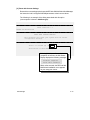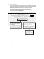
1
DEChub 900 MultiSwitch Owner’s Manual Part Number: EK–DH2MS–OM. B01 April 1994 Revision/Update Information: This is a revised manual. April 1994 The information in this document is subject to change without notice and should not be construed as a commitment by Digital Equipment Corporation. Digital Equipment Corporation assumes no responsibility for any errors that may appear in this document. Copyright 1994 by Digital Equipment Corporation. All rights reserved. Printed in U.S.A. The postage-paid Reader’s Comments form at the back of this document requests your evaluation of this document to assist us in preparing future documentation. The following are trademarks of Digital Equipment Corporation: DEC, DECagent, DECbridge, DECconnect, DEChub, DEChub ONE, DECndu, DECndu Plus, DECrepeater, DECserver, Digital, MultiSwitch, OpenVMS, ThinWire, ULTRIX, VAX, VMS, and the DIGITAL logo. MS–DOS is a registered trademark of Microsoft Corporation. UNIX is a registered trademark licensed exclusively by X/Open Company, Ltd. FCC NOTICE — Class A Computing Device: This equipment generates, uses, and may emit radio frequency energy. The equipment has been type tested and found to comply with the limits for a Class A computing device pursuant to Subpart J of Part 15 of FCC Rules, which are designed to provide reasonable protection against such radio frequency interference when operated in a commercial environment. Operation of this equipment in a residential area may cause interference; in which case, measures taken to correct the interference are at the user’s expense. VCCI NOTICE — Class 1 Computing Device: This equipment is in the 1st Class category (information equipment to be used in commercial and/or industrial areas) and conforms to the standards set by the Voluntary Control Council for Interference by Data Processing Equipment and Electronic Office Machines aimed at preventing radio interference in commercial and/or industrial areas. Consequently, when used in a residential area or in an adjacent area thereto, radio interference may be caused to radios and TV receivers. Read the instructions for correct handling. CE NOTICE – Class A Computing Device: Warning! This is a Class A product. In a domestic environment this product may cause radio interference, in which case the user may be required to take adequate measures. Achtung! Dieses ist ein Gerät der Funkstörgrenzwertklasse A. In Wohnbereichen können bei Betrieb dieses Gerätes Rundfunkstörungen auftreten, in welchen Fällen der Benutzer für entsprechende Gegenmaßnahmen verantwortlich ist. Attention! Ceci est un produit de Classe A. Dans un environment domestique, ce produit risque de créer des interférences radioélectriques, il appartiendra alors à l’utilisateur de prendre les mesures spécifiques appropriées. Contents Preface Intended Audience . . . . . . . . . . . . . . . . . . . . . . . . . . . . . . . . . . . . . . . . . . . . . . . Structure of This Manual . . . . . . . . . . . . . . . . . . . . . . . . . . . . . . . . . . . . . . . . . . Conventions Used in This Manual . . . . . . . . . . . . . . . . . . . . . . . . . . . . . . . . . . Safety . . . . . . . . . . . . . . . . . . . . . . . . . . . . . . . . . . . . . . . . . . . . . . . . . . . . . . . . . . Related Documentation . . . . . . . . . . . . . . . . . . . . . . . . . . . . . . . . . . . . . . 1 Overview DEChub 900 MultiSwitch Hub Features . . . . . . . . . . . . . . . . . . . . . . . . . . . . . DEChub 900 MultiSwitch Hub Description . . . . . . . . . . . . . . . . . . . . . . . . . . . Hub Power System Overview . . . . . . . . . . . . . . . . . . . . . . . . . . . . . . . . . . . . . 2 ix ix x xi xvi 1–2 1–4 1–8 Installing the Chassis and Power Supply Module Before You Install the Chassis . . . . . . . . . . . . . . . . . . . . . . . . . . . . . . . . . . . . . Checking the Contents . . . . . . . . . . . . . . . . . . . . . . . . . . . . . . . . . . . . . . . . . Gathering the Tools . . . . . . . . . . . . . . . . . . . . . . . . . . . . . . . . . . . . . . . . . . . . Installing the Chassis in a Rack . . . . . . . . . . . . . . . . . . . . . . . . . . . . . . . . . . . . Installing the Chassis on a Wall . . . . . . . . . . . . . . . . . . . . . . . . . . . . . . . . . . . . Installing the Wall Mounting Bracket . . . . . . . . . . . . . . . . . . . . . . . . . . . . . Attaching the Mounting Hanger . . . . . . . . . . . . . . . . . . . . . . . . . . . . . . . . . . Sliding the Chassis onto the Wall Mounting Bracket . . . . . . . . . . . . . . . . Installing and Removing a Power Supply Module . . . . . . . . . . . . . . . . . . . . 2–1 2–2 2–2 2–3 2–6 2–6 2–8 2–9 2–10 iii Resetting the Power System . . . . . . . . . . . . . . . . . . . . . . . . . . . . . . . . . . . . . . Resetting a Non-Battery Backup Power System . . . . . . . . . . . . . . . . . . . Resetting a Battery Backup Power System . . . . . . . . . . . . . . . . . . . . . . . Optional Mounting Methods . . . . . . . . . . . . . . . . . . . . . . . . . . . . . . . . . . . . . . . 3 Hub Manager Hub Manager Functions . . . . . . . . . . . . . . . . . . . . . . . . . . . . . . . . . . . . . . . . . . Hub Manager Ports . . . . . . . . . . . . . . . . . . . . . . . . . . . . . . . . . . . . . . . . . . . . . . Hub Setup Port . . . . . . . . . . . . . . . . . . . . . . . . . . . . . . . . . . . . . . . . . . . . . . . . Hub Out-of-Band Management (OBM) Port . . . . . . . . . . . . . . . . . . . . . . . Hub Status Display . . . . . . . . . . . . . . . . . . . . . . . . . . . . . . . . . . . . . . . . . . . . . . Self-Test Procedure . . . . . . . . . . . . . . . . . . . . . . . . . . . . . . . . . . . . . . . . . . . . . . Using the Hub Setup Port . . . . . . . . . . . . . . . . . . . . . . . . . . . . . . . . . . . . . . . . . Connecting a Terminal to the Hub Setup Port . . . . . . . . . . . . . . . . . . . . . Hub Setup Port Menu . . . . . . . . . . . . . . . . . . . . . . . . . . . . . . . . . . . . . . . . . . Hub Setup Port Menu Options . . . . . . . . . . . . . . . . . . . . . . . . . . . . . . . . . . 4 4–1 4–2 4–3 4–3 4–3 Hub Power System Redundant Power . . . . . . . . . . . . . . . . . . . . . . . . . . . . . . . . . . . . . . . . . . . . . . . Guidelines for Calculating Power Needs . . . . . . . . . . . . . . . . . . . . . . . . . . . . Power System Monitoring . . . . . . . . . . . . . . . . . . . . . . . . . . . . . . . . . . . . . . . . . Hub Status Display Power Messages . . . . . . . . . . . . . . . . . . . . . . . . . . . . Power Allocation . . . . . . . . . . . . . . . . . . . . . . . . . . . . . . . . . . . . . . . . . . . . . . Installing and Removing Network Modules . . . . . . . . . . . . . . . . . . . . . . . . . . iv 3–1 3–2 3–2 3–4 3–5 3–9 3–10 3–10 3–11 3–12 Network Management Managing Network Modules In-Band . . . . . . . . . . . . . . . . . . . . . . . . . . . . . . . Using the In-Band IP Address of the Hub Manager . . . . . . . . . . . . . . . . . Using the Out-of-Band IP Address of the Hub Manager . . . . . . . . . . . . . Using the IP Address of the DECagent 90 . . . . . . . . . . . . . . . . . . . . . . . . Managing Network Modules Out-of-Band . . . . . . . . . . . . . . . . . . . . . . . . . . . 5 2–12 2–12 2–12 2–13 5–1 5–2 5–4 5–4 5–4 5–5 6 Problem Solving A Order Numbers and Specifications Country-Specific Order Numbers . . . . . . . . . . . . . . . . . . . . . . . . . . . . . . . . . . Related Parts . . . . . . . . . . . . . . . . . . . . . . . . . . . . . . . . . . . . . . . . . . . . . . . . . . . Specifications . . . . . . . . . . . . . . . . . . . . . . . . . . . . . . . . . . . . . . . . . . . . . . . . . . . Mechanical Specifications . . . . . . . . . . . . . . . . . . . . . . . . . . . . . . . . . . . . . . Electrical Specifications . . . . . . . . . . . . . . . . . . . . . . . . . . . . . . . . . . . . . . . . Environmental Specifications . . . . . . . . . . . . . . . . . . . . . . . . . . . . . . . . . . . Acoustic Specifications . . . . . . . . . . . . . . . . . . . . . . . . . . . . . . . . . . . . . . . . . B Connector, Cable and Adapter Pin Assignments C Accessing MIBs and RFCs Using Electronic Mail . . . . . . . . . . . . . . . . . . . . . . . . . . . . . . . . . . . . . . . . . . . . . Using ftpmail . . . . . . . . . . . . . . . . . . . . . . . . . . . . . . . . . . . . . . . . . . . . . . . . . . . . Using Anonymous ftp . . . . . . . . . . . . . . . . . . . . . . . . . . . . . . . . . . . . . . . . . . . . DEChub 900 MultiSwitch Supported MIBs . . . . . . . . . . . . . . . . . . . . . . . . . . Obtaining Firmware Upgrades . . . . . . . . . . . . . . . . . . . . . . . . . . . . . . . . . . . . . A–1 A–2 A–2 A–2 A–4 A–4 A–5 C–1 C–2 C–4 C–6 C–6 Index v Figures vi 1–1 The DEChub 900 MultiSwitch Hub . . . . . . . . . . . . . . . . . . . . . . . . . 1–3 1–2 Connector Backplane Data Path Interconnects . . . . . . . . . 1–5 1–3 2–1 2–2 2–3 2–4 2–5 2–6 2–7 The DEChub 900 MultiSwitch Chassis . . . . . . . . . . . . . . . . . . . . . . Attaching Rack Mount Brackets to the Chassis . . . . . . . . . . . . . . . Cable Ring Bracket on a 19-inch Rack . . . . . . . . . . . . . . . . . . . . . . Installing the Wall Mounting Bracket . . . . . . . . . . . . . . . . . . . . . . . . Attaching the Mounting Hanger . . . . . . . . . . . . . . . . . . . . . . . . . . . . Sliding the Chassis onto the Wall Mounting Bracket . . . . . . . . . . . Installing the Power Supply Module . . . . . . . . . . . . . . . . . . . . . . . . . DEChub 900 MultiSwitch mounted on a DERMS–AA . . . . . . . . . 1–6 2–4 2–5 2–7 2–8 2–9 2–11 2–14 2–15 3–3 B–1 B–2 B–2 B–3 B–3 B–4 B–4 2–8 DEChub 900 MultiSwitch DERMS–DA Cover . . . . . . . . . . 3–1 B–1 B–2 B–3 B–4 B–5 B–6 B–7 Setup Port and OBM Port Cabling . . . . . . . . . . . . . . . . . . . . . . . . . . Setup Port (8 MJ) Connector Pin Assignments . . . . . . . . . . . . . . . OBM Port (DB-9) Connector Pin Assignments . . . . . . . . . . . . . . . BC29P Cable Pin Assignments . . . . . . . . . . . . . . . . . . . . . . . . . . . . BC29Q Cable Pin Assignments . . . . . . . . . . . . . . . . . . . . . . . . . . . . BN24H Cable Pin Assignments . . . . . . . . . . . . . . . . . . . . . . . . . . . . H8571-J Adapter Pin Assignments . . . . . . . . . . . . . . . . . . . . . . . . . H8575-A Adapter Pin Assignments . . . . . . . . . . . . . . . . . . . . . . . . . Tables 2–1 3–1 3–2 3–3 3–4 5–1 5–2 6–1 A–1 A–2 A–3 A–4 A–5 A–6 A–7 A–8 A–9 A–10 A–11 Dechub 900 MultiSwitch Kit Content1 . . . . . . . . . . . . . . . . . . . . . . . Setup Port Cabling . . . . . . . . . . . . . . . . . . . . . . . . . . . . . . . . . . . . . . . OBM Port Cabling . . . . . . . . . . . . . . . . . . . . . . . . . . . . . . . . . . . . . . . . Hub Status Display Messages . . . . . . . . . . . . . . . . . . . . . . . . . . . . . Terminal Setup Parameters . . . . . . . . . . . . . . . . . . . . . . . . . . . . . . . . DEChub 900 MultiSwitch System Power . . . . . . . . . . . . . . . . . . . . Power Example . . . . . . . . . . . . . . . . . . . . . . . . . . . . . . . . . . . . . . . . . . Problem Solving the DEChub 900 MultiSwitch . . . . . . . . . . . . . . . DEChub 900 MultiSwitch Order Numbers . . . . . . . . . . . . . . . . . . . Related Parts . . . . . . . . . . . . . . . . . . . . . . . . . . . . . . . . . . . . . . . . . . . . Chassis Specifications . . . . . . . . . . . . . . . . . . . . . . . . . . . . . . . . . . . . Component Weight Specifications . . . . . . . . . . . . . . . . . . . . . . . . . . Rack Mount Option Dimension Specifications . . . . . . . . . . . . . . . . Rack Mount Option Clearance Specifications . . . . . . . . . . . . . . . . Wall Mount Option Specifications . . . . . . . . . . . . . . . . . . . . . . . . . . . Electrical Specifications . . . . . . . . . . . . . . . . . . . . . . . . . . . . . . . . . . . Environmental Specifications . . . . . . . . . . . . . . . . . . . . . . . . . . . . . . Acoustical Specifications – English . . . . . . . . . . . . . . . . . . . . . . . . . Acoustical Specifications – German . . . . . . . . . . . . . . . . . . . . . . . . 2–2 3–2 3–4 3–5 3–10 5–2 5–3 6–1 A–1 A–2 A–2 A–3 A–3 A–3 A–4 A–4 A–4 A–5 A–6 vii Preface This manual provides an overview of the DEChub 900 MultiSwitch hub. It also describes how to install, manage, and troubleshoot the hub. Intended Audience This manual is for personnel who will install and use the DEChub 900 MultiSwitch hub. Structure of This Manual This manual has six chapters and three appendixes, as follows: Chapter Description 1 Provides an overview of the DEChub 900 MultiSwitch hub. 2 Describes how to install the DEChub 900 MultiSwitch hub. 3 Describes the Hub Manager. 4 Describes network management. 5 Describes the hub power system. 6 Provides problem solving information for the hub. Appendix A Describes the mechanical, electrical, and acoustic specifications, and provides country–specific order numbers. Appendix B Provides connector, cable, and adapter pin assignment information. Appendix C Provides information about related RFCs and Digital Private MIBs. ix Conventions Used in This Manual This manual uses the following conventions: x 1 A number in a black circle in text refers to the corresponding number in an accompanying figure. Special type Indicates a literal example of system output. bold Indicates a command format that you enter. italic type Indicates a variable for which you specify a value. Also used to emphasize complete titles of manuals. Key Indicates that you press the specified key. For example, Return means that you press the Return key. Ctrl/x Indicates that you hold down the Control key and then press the key specified by x. Ethernet Digital’s term for its product compatibility with the ISO 8802–3/ANSI/IEEE 802.3 standards and the Ethernet standards for CSMA/CD local area networks (LANs). Token Ring Refers to the IEEE 802.5 standard. Mb/s Mb/s is an abbreviation for megabits per second. Safety ! Any warning or caution that appears in this manual is defined in English, German, French, and Spanish as follows: WARNING Contains information to prevent personal injury VORSICHT Enthält Informationen, die beachtet werden müssen, um den Benutzer vor Schaden zu bewahren. DANGER Signale les informations destinées à prévenir les accidents corporels. AVISO Contiene información para evitar daños personales CAUTION Contains information to prevent damage to equipment ACHTUNG Enthält Informationen, die beachtet werden müssen, um die Geräte vor Schaden zu bewahren ATTENTION Signale les informations destinées à prévenir la détérioration du matériel PRECAUCION Contiene información para evitar daños al equipo. xi The pages where the following safety messages appear are also listed. WARNING xii ! This is a Class A product. In a domestic environment this product may cause radio interference, in which case the user may be required to take adequate measures. VORSICHT Dieses ist ein Gerät der Funkstörgrenzwertklasse A. In Wohnbereichen können bei Betrieb dieses Gerätes Rundfunkstörungen auftreten, in welchen Fällen der Benutzer für entsprechende Gegenmaßnahmen verantwortlich ist. DANGER Ceci est un produit de Classe A. Dans un environment domestique, ce produit risque de créer des interférences radioélectriques, il appartiendra alors à l’utilisateur de prendre les mesures spécifiques appropriées. AVISO Éste es un producto de Clase A. En entornos domésticos, este producto puede causar radio–interferencias, en cuyo caso el usuario puede estar obligado a tomar las medidas adecuadas. CAUTION ! The total weight of a fully configured DEChub 900 MultiSwitch chassis with modules and cables is approximately 80 pounds. [Page 2–6] This configuration is too heavy for an office wall partition. Be sure to install the chassis on a solid wall. [Page 2–6] ACHTUNG Das Gesamtgewicht einer vollständig konfigurierten Geräts vom Typ DEChub MultiSwitch beträgt etwa 36 kg. Diese Konfiguration ist für Leichtbauwände zu schwer. Hängen Sie das Gerät nur an stabilen Wänden auf. ATTENTION La configuration totale d’un châssis DEChub 900 MultiSwitch, avec modules et câbles, pèse environ 36kg. Ce poids étant trop élevé pour une cloison mobile, le châssis doit être installé contre un mur fixe. PRECAUCION El peso total des chasis de un DEChub 900 MultiSwitch plenamente configurado con módulos y cables es aproximadamente de 36 kilos. Esta configuración es demasiado pesada para une mámpara de oficina, por lo cual el chasis debe instalarse en una pared resistente. WARNING ! To avoid bodily injury or equipment damage, be sure to lock the power supply into place to prevent it from falling out. [Page 2–10] VORSICHT Zur Vorbeugung von Personen– oder Sachschäden muß das Netzteil korrekt befestigt werden, damit es nicht herausfällt. DANGER Pour éviter tout risque d’endommagement du matériel ou d’accident corporel, fixez correctement le bloc d’alimentation. AVISO Para evitar daños personales o al equipo, asegúrese de cerrar la fuente de alimentación en su lugar a fin de evitar su caída. xiii WARNING To avoid bodily injury or equipment damage, use care when connecting the power cord. [Page 2–10] VORSICHT Um mögliche Verletzungen oder Geräteschäden durch elektrischen Strom zu vermeiden, seien Sie besonders vorsichtig, wenn Sie das Netzkabel anschliessen. DANGER Lors de la connexion du cordon d’alimentation, prenez toutes les précautions nécessaires afin d’éviter tout risque corporel ou dommage matériel. AVISO Para evitar daños corporales o al equipo, póngase la debida atención al conectar el cable de alimentación. WARNING xiv ! ! Operational power supplies may be hot; use care when removing a power supply. [Page 2–12] VORSICHT Im Dauerbetrieb könnte das Netzteil sich erhitzen. Seien Sie deshalb vorsichtig, wenn Sie das Netzteil herausnehmen. DANGER Les blocs d’alimentation pouvant être très chauds, prenez toutes les précautions pour les retirer. AVISO Las fuentes de alimentación en funcionamiento pueden estar calientes, por lo que se deberán extremar los cuidados al retirarlas. CAUTION ! This action deletes all configured settings and replaces them with factory default values. All configuration settings will be lost. [Page 3–12] ACHTUNG Bei diesem Vorgang werden alle Konfigurationseinstellungen gelöscht und die Werkseinstellungen wieder eingesetzt. Alle Konfigurationsdaten gehen verloren. ATTENTION Cette action supprime tous les paramètres de configuration et les remplace par des valeurs prédéfinies. Tous les paramètres de configuration seront perdus. PRECAUCION Esta intervención borrará todos los parámetros de configuración y los sustituirá por valores por defecto definidos de fábrica. Se perderán todos los parámetros de configuración. CAUTION ! If power is interrupted during a downline load, the firmware image can become corrupted. Do not turn off power to the unit or perform any action to the unit to lose power during a downline upgrade. [Page 3–20] ACHTUNG Wenn die Stromversorgung während des Fernladens unterbrochen wird, besteht die Gefahr, daß die Firmwaredaten zerstört werden. Während der Durchführung der Ferninstallation der Firmware müssen Sie daher unter allen Umständen dafür Sorge tragen, daß die Stromversorgung des Geräts nicht unterbrochen werden kann. ATTENTION Une coupure de courant au cours de la procédure de téléchargement peut entraîner la détérioration de l’image du microprogramme. Ne mettez pas l’unité hors tension et n’exécutez une action pouvant provoquer une coupure de courant au cours de cette procédure. PRECAUCION Si ocurre una interrupción del suministro durante la carga desde el sistema central, puede corrompirse la imagen del firmware. No se debe apagar el dispositivo, ni tomar ninguna medida que pueda producir un corte de la alimentación durante una actualización por telecarga. xv Related Documentation You can order the following documents from Digital: Document Title xvi Description HUBwatch Installation and Configuration AA–Q0FXB–TE Provides information for installing and configuring HUBwatch for Open VMS V3.0 and HUBwatch for Windows V2.0. HUBwatch Installation and Configuration AA–Q3S8A–TE Provides information for installing and configuring HUBwatch for Open VMS V2.0 and HUBwatch for Windows V2.0. HUBwatch Use AA–PW4BC–TE Provides network management, and DEChub 900, DEChub 90, DEChub ONE functionality information for HUBwatch for Open VMS V3.0. HUBwatch for Windows Use AA–Q3S3A–TE Provides network management, and DEChub functionality information for HUBwatch for Windows V2.0. OPEN DECconnect Applications Guide EC–G2570–42 Provides information to help plan and install networking systems based on Digital’s OPEN DECconnect System and networking products. Using DECndu Plus (MS–DOS) AA–PYVVA–TE Provides instructions to upgrade the firmware in an MS–DOS environment of selected network devices using Digital’s Network Device Upgrade (DECndu) Plus utility. Using DECndu Plus (ULTRIX RISC) AA–PYVTA–TE Provides instructions to upgrade the firmware in an ULTRIX RISC environment of selected network devices using Digital’s Network Device Upgrade (DECndu) Plus utility. Using DECndu Plus (OpenVMS VAX) AA–PYVRA–TE Provides instructions to upgrade the firmware in an OpenVMS VAX environment of selected network devices using Digital’s Network Device Upgrade (DECndu) Plus utility. 1 Overview This chapter describes the DEChub 900 MultiSwitch hub. It includes an overview of the features, and it describes the hub power system and backplane capabilities. The DEChub 900 MultiSwitch hub complements Digital’s DEChub 90 and DEChub ONE family of products. The DEChub 900 MultiSwitch hub uses advanced hub technology to provide complete backward compatibility with the DEChub 90 network modules. The DEChub 900 MultiSwitch hub with either DEChub 90 or DEChub 900 MultiSwitch series network modules installed becomes an integral part of any distribution subsystem within a structured wiring environment. This hub is a high density hub that is capable of supporting multiple network technologies. A flexible channel architecture is used to support Ethernet, Token Ring, and fiber distributed data interface (FDDI) technologies, as well as higher speed emerging technologies such as asynchronous transfer mode (ATM). The DEChub 900 MultiSwitch uses industry standard Simple Network Management Protocol (SNMP) and a network management station (NMS) with native SNMP to manage the hub with in-band and out-of-band support. 1–1 DEChub 900 MultiSwitch Hub Features The DEChub 900 MultiSwitch (see Figure 1–1) has many advanced hub capabilities. The following list describes the DEChub 900 MultiSwitch hub features: DEChub 900 MultiSwitch Hub Features • Supports all the DEChub 90 series network modules • Has no slot restrictions for any network module • Allows for ”hot swap” of power supply and network modules • Uses Simple Network Management Protocol (SNMP) • Provides a built-in hub management agent that includes: – Configuration and control of the hub and modules that are in the hub – Hub setup port – Hub out-of-band management (OBM) port – Hub Status Display – Chassis Management Information Base (MIB) • Provides an auto-ranging redundant power system with support for external input of 48-volt backup power • Provides a power management interface to each network module • Provides a MultiSwitch backplane with flexible channel bandwidth allocation that includes: 1–2 – Supports Token Ring, FDDI, and Ethernet technologies – Supports future technologies, such as ATM – A total bandwidth in excess of 3 gigabits per second – Dynamic reconfiguration of network modules DEChub 900 MultiSwitch Owner’s Manual Figure 1–1: The DEChub 900 MultiSwitch Hub Hub Status Display Power supply modules Half-height network modules Full-height network modules LKG-8263-93I Overview 1–3 DEChub 900 MultiSwitch Hub Description The DEChub 900 MultiSwitch hub implements a management architecture designed to manage multiple local area networks (LANs) using the Simple Network Management Protocol (SNMP) integrated into the chassis’s Hub Manager. The DEChub 900 MultiSwitch hub backplane (see Figure 1–2) contains two independent Token Ring channels, one dedicated Ethernet channel, and one flexible channel on the top row of connectors. The bottom row of connectors provides 14 flexible channels for full-height modules. The multiple flexible channels can be used to create independent LAN segments within the hub. Using HUBwatch, network modules can be linked to LAN segments and to share data between them. The use of the flexible channels on the chassis is dependent on the network modules installed in the hub. Specific implementations allow these channels to be used for FDDI, Ethernet, and Token Ring. The Hub Manager allocates these technology independent flexible channels to modules as needed, to provide for backplane interconnect needs. Channels may be supported as a bus for shared use (like Ethernet) or cascaded for LANs requiring ring-like implementations. The chassis can be configured for up to eight network modules and four power supply modules. The network modules may be installed, in any combination, in slots1 to 8. Figure 1–3 and the list that follows it show the MultiSwitch chassis and describe its components. The chassis provides all the power and interconnect signals to each network module through a backplane connector. The network modules and power supply modules can be installed or swapped with the power on. This is referred to as a hot swap. Hot swapping allows for upgrades, modifications, or replacement of modules without interruption to other users on the hub. 1–4 DEChub 900 MultiSwitch Owner’s Manual Figure 1–2: Connector Backplane Data Path Interconnects DEChub 900 MultiSwitch 1 2 3 4 5 6 7 1 2 Power supply connectors 8 Ethernet ThinWire Flexible channel Token Ring A Token Ring B 3 4 Power supply connectors 14 Flexible channels LKG-8310-93I Overview 1–5 Figure 1–3: The DEChub 900 MultiSwitch Chassis 11 12 10 13 9 8 1 10 9 2 8 3 4 7 3 6 5 Bottom view LKG-8264-93I 1–6 DEChub 900 MultiSwitch Owner’s Manual 1 Release lever – Releases the backplane latching mechanism when removing and installing network modules. 2 Backplane connector – Provides power, network connection, and management signals to network modules. 3 Module mounting slot – Secures the lower mounting tab of a network module. The slots for modules are numbered 1 through 8 from left to right. 4 MultiSwitch connector – Provides additional power for full-height network modules with power management. Also provides access to flexible channels, and connections between modules for control, data, and clock signals. 5 Battery backup disable switch – With a battery backup installed, this switch allows a power system interruption when the ac power cord is removed. 6 AC connector – Provides ac power to the power supply system. 7 External battery connector – Provides external battery power to the hub (48 volts). 8 Power supply mounting slot – Secures the lower mounting tab of the power supply. The power supply slots are numbered 1 through 4 from left to right and top to bottom. 9 Power supply connector – Provides +5.0 volts and +15.0 volts power from the power supply to the backplane. 10 Power ac input connector – Provides ac power to the power supply module. 11 Hub out-of-band management (OBM) port – Provides serial access to the Hub Manager over serial line internet protocol (SLIP). The hub OBM port provides modem control. 12 Hub setup port – Provides a local terminal access to the Hub Manager. 13 Hub Status Display – Provides self-test and operational status of the hub and modules within the hub. Overview 1–7 Hub Power System Overview The DEChub 900 MultiSwitch hub power system can: • Power a fully-configured hub with power redundancy • Monitor the power activity • Calculate the power available to network modules • Display the power status and available power • Allocate power to network modules. The power system consists of 1 to 4 power supply modules, and a Hub Manager that monitors and polls each power supply for identification and status. The hub power system is designed to allow for the installation of incremental power supply modules as the hub system needs expand. Up to four power supply modules can be installed into the hub with all power supply modules sharing power delivery to the chassis and to the network modules on a common bus. Fully configuring a DEChub 900 MultiSwitch with half-height network modules typically requires only a single power supply module. An additional power supply module provides power redundancy. You provide redundancy to the power system by adding an extra power supply module beyond what is needed to power the hub with installed network modules. For example, if a single power supply module provides enough power for the hub, and you add a second power supply module, then the hub has redundant (N+1) power. If either of the power supply modules fail, the hub continues to operate without interruption. The Hub Manager monitors the power system for power supply modules that may have been inserted or removed from the hub. When changes are detected in the power system, the Hub Manager updates the amount of power available to the network modules, and determines if: 1–8 • The system is underpowered or adequately powered with all network modules powered up. • The hub platform is configured as N+1 (or more) for redundant power system operation. DEChub 900 MultiSwitch Owner’s Manual Power supply modules can be hot swapped while the DEChub 900 MultiSwitch hub is operating. This feature allows you to remove faulty power supply modules, add extra power supply modules, or move power supply modules to other slots without interrupting power or network modules. If a power supply module fails or is removed from a hub that is not configured for N+1 redundancy, then the hub does not have sufficient power for operation. If this occurs, then the hub powers down as many full-height network modules as required to balance the demand for power and the load. Network modules are powered up from right (slot 8) to left (slot 1) and are powered down from left to right. The Hub Manager monitors the power system and displays power system messages in the Hub Status Display. The Hub Manager power display messages that appear provide you with information on the power system status, and on the amount of power available in the hub. This information, in addition to the power needs of a network module (from the module label), lets you determine if enough power exists to install a network module in the hub. At hub powerup, power is automatically supplied to the chassis, the Hub Manager, and all half-height network modules. Also at powerup, the Hub Manager calculates the total power available from the power system. If you install additional power supply modules in an operational hub, the Hub Manager recalculates the total power available. You can install or remove network modules on an operational DEChub 900 MultiSwitch without having to power down the hub, and without disturbing other network modules or their configuration. Refer to Chapter 5 for additional information on the hub power system. Overview 1–9 2 Installing the Chassis and Power Supply Module This chapter provides procedures for installing the DEChub 900 MultiSwitch chassis on a wall or in a rack and procedures for installing the power supply module. It also illustrates optional wall mounting kits available. Before You Install the Chassis Before you begin the installation, you should: • Unpack the box, and check the contents. • Gather the tools that you need to perform the installation. 2–1 Checking the Contents Before you begin the installation, unpack the contents of the box and be sure that you have the parts listed in Table 2–1. Table 2–1: Dechub 900 MultiSwitch Kit Content1 Item Quantity 1 DEChub 900 MultiSwitch chassis 1 Power supply module 1 ac power cord 2 Rack mount brackets (one left, one right) 1 H3108–CR cable ring bracket 10 #6–32 x 5/16-inch machine screws 8 #10–32 x 1/2-inch machine screws 8 #10–32 U-nuts 1 Wall mounting bracket 1 Wall mounting hanger 2 Rubber feet 9 #8 wood screws 4 #8–32 x 1/2-inch machine screws (used with DERMS–AA) 1 Cable, 8 MP to 6 MMP (BN24H) 1 Cable adapter, 6 MMJ to 25-pin D-Sub (H8575–A) 1 License, assembly kit 1 DEChub 900 MultiSwitch Owner’s Manual 1Appendix A lists the country specific kit variations and other related parts. Gathering the Tools Use the following tools to install the chassis: • A Phillips screwdriver • A drill with a 1/8-inch (3.1 mm) bit (for wall mount only) You are now ready to install the chassis. 2–2 DEChub 900 MultiSwitch Owner’s Manual Installing the Chassis in a Rack The DEChub 900 MultiSwitch chassis can be installed either in a 19-inch equipment rack or on a wall using the mounting bracket and hanger. Rack mount brackets and mounting hardware, for installing the chassis into a standard RETMA 19-inch equipment rack, are supplied with the DEChub 900 MultiSwitch chassis (see Figure 2–1). You can use the cable ring bracket supplied with your chassis to manage the cabling from the network modules (see Figure 2–2). This bracket accommodates eight cable rings. You can snap the cable rings into the holes in the bracket and then route cables through the rings. Perform the following four steps to install the chassis in the equipment rack: 1. Locate the rack mount brackets and the ten #6–32 machine screws that are supplied with the chassis. 2. Attach the rack mount brackets, using the #6–32 screws, to the back of the chassis. 3. Install the chassis in the equipment rack using the eight #10–32 machine screws and U-nuts (if necessary). 4. Install the ac power cord into the ac connector at the bottom of the chassis. 5. Some rack mount bracket assemblies have a punchout on the right rack mount bracket, which is used to attach a cable tie. If your assembly has a punchout, secure the ac power cord to the punchout using a cable tie. Installing the Chassis and Power Supply Module 2–3 Figure 2–1: Attaching Rack Mount Brackets to the Chassis Back view LKG-9008-94I 2–4 DEChub 900 MultiSwitch Owner’s Manual Figure 2–2: Cable Ring Bracket on a 19-inch Rack AC power cable tie Cable ring bracket LKG-8987-94I Installing the Chassis and Power Supply Module 2–5 Installing the Chassis on a Wall The chassis can be mounted directly on a wall using the wall bracket and hanger mounting device. CAUTION ! The total weight of a fully configured DEChub 900 MultiSwitch chassis with network modules and cables is approximately 80 pounds (36 kg). This configuration is too heavy for an office wall partition. Be sure to install the chassis on a wall that can support the weight. Installing the Wall Mounting Bracket Perform the following five steps to install the wall mounting bracket: 1. Mark the location for the nine #8 wood screws. Digital recommends that you place the screws so that the LED indicators on the network modules will be at eye level. 2. Using a 1/8-inch (3.1 mm) bit, drill pilot holes at the locations marked on the wall. 3. Place the mounting bracket over the drilled holes. 4. Screw two #8 wood screws into the pilot holes at each end of the mounting bracket until each head is approximately 1/8-inch from the surface of the mounting bracket. 5. Ensure that the mounting bracket is straight and level. Place screws in the remaining pilot holes and tighten the screws (see Figure 2–3). 2–6 DEChub 900 MultiSwitch Owner’s Manual Figure 2–3: Installing the Wall Mounting Bracket LKG-8266-93I Installing the Chassis and Power Supply Module 2–7 Attaching the Mounting Hanger Perform the following two steps to mount the hanger to the chassis (see Figure 2–4): 1. Attach the wall mounting hanger (1) to the back of the chassis using six #6–32 screws. 2. Attach the rubber feet (2) to the back of the chassis using two #6–32 screws. Figure 2–4: Attaching the Mounting Hanger Rear of chassis Wall mounting hanger 1 2 LKG-8997-94I 2–8 DEChub 900 MultiSwitch Owner’s Manual Sliding the Chassis onto the Wall Mounting Bracket To mount the chassis, slide the chassis onto the wall mounting bracket (see Figure 2–5). Figure 2–5: Sliding the Chassis onto the Wall Mounting Bracket Side view LKG-8268-93I Installing the Chassis and Power Supply Module 2–9 Installing and Removing a Power Supply Module You can install a power supply module into any power supply slot. Perform the following three steps to install a power supply module (see Figure 2–6): 1. Ensure that the power supply locking mechanism is in the unlock position. 2. Place the mounting tab, which is located on the bottom of the power supply module, in the mounting slot of the chassis. 1 3. Align the power supply connector with the backplane connector and pivot the power supply module into place. Check the alignment of the power supply connector and backplane connector as the power supply module is pivoted into place. 2 WARNING ! To avoid bodily injury or equipment damage, be sure to lock the power supply module into place to prevent it from falling out. 4. Turn the mounting rod 90 degrees to the left (clockwise) to lock the power supply into place. 3 You can install the ac power cord by performing the following three steps: WARNING ! To avoid bodily injury or equipment damage, use care when connecting the power cord. 1. Install the ac power cord into the ac connector at the bottom of the chassis. 2. Plug the ac power cord into a working ac outlet. 3. Verify that the two LEDs (AC OK and DC OK ) on the power supply module turn on, and that the Hub Manager begins the self-test procedure. The Hub Manager indicates the start of the self-tests by displaying various test numbers across the Hub Status Display. After the self-test procedure is complete, the Hub Manager begins normal operation. 2–10 DEChub 900 MultiSwitch Owner’s Manual Figure 2–6: Installing the Power Supply Module 2 1 3 LKG-8998-93I Installing the Chassis and Power Supply Module 2–11 If you install any additional power supply modules to the DEChub 900 MultiSwitch once it is operational, you may observe a momentary flicker in the power supply LEDs each time a new power supply module is added. This is part of the normal installation power up sequence when adding additional power supply modules. This task does not cause a dc power interruption to the hub or the network modules. You are now ready to install network modules into the chassis and make the necessary network connections. Refer to each network module’s documentation for installation procedures. Power supply modules can be removed while the hub is operational. To remove a power supply module, perform the following two steps: WARNING ! Operational power supply modules are heavy, and may be hot; use care when removing a power supply module. 1. Turn the locking mechanism 90 degrees to the right (counterclockwise) to unlock the power supply. 2. Remove the power supply module from the DEChub 900 MultiSwitch. Resetting the Power System The following sections describe how to reset the power system. Resetting a Non-Battery Backup Power System If you have a non-battery backup power system and you need to reset the entire hub and power system, cycle the power by removing the ac power cord. Resetting a Battery Backup Power System If you have a battery backup power system and you need to reset the entire hub and power system, cycle the power by removing the ac power cord and pressing the battery backup disable switch located near the ac connector. When the battery backup disable switch is pressed, the battery backup is disabled. With the ac power and battery removed, the system powers down and can only be restarted by plugging in the ac power cord. 2–12 DEChub 900 MultiSwitch Owner’s Manual Optional Mounting Methods Digital offers optional mounting kits you can use to mount your hub. The following list contains kits you can purchase from Digital. Figure 2–7 shows a DEChub 900 MultiSwitch mounted on a DERMS–AA wall mount rail system, and Figure 2–8 shows a DEChub 900 MultiSwitch DERMS–DA cover. • DERMS–AA wall mount rail system starter kit • DERMS–DA cover • H3108–CW cable ring bracket wall mount • H3108–CS cable ring bracket For ordering information and descriptions of these options, refer to the OPEN DECconnect Applications Guide, order number EC–G2570–42. Installing the Chassis and Power Supply Module 2–13 Figure 2–7: DEChub 900 MultiSwitch mounted on a DERMS–AA DERMS-AA H3108-CS H3108-CW LKG–9087–94I 2–14 DEChub 900 MultiSwitch Owner’s Manual Figure 2–8: DEChub 900 MultiSwitch DERMS–DA Cover DERMS-AA DERMS-DA LKG-9086-94I Installing the Chassis and Power Supply Module 2–15 3 Hub Manager This chapter describes the features and functionality of the Hub Manager, including the setup port, the out-of-band management port, the Hub Status Display, and selftest procedures. The Hub Manager is a replaceable microprocessor-based controller used to monitor, configure, and control the hub. It provides a central point for status and control for allocation of hub resources to hub-mounted network modules, either under remote management or local control. Hub Manager Functions The Hub Manager has the following functions: • Provides a simple network management protocol (SNMP) agent that provides control and status information. • Identifies installed network modules and available slot locations. • Identifies media access control (MAC) and internet protocol (IP) addresses of network modules for direct in-band communication from the network management station. • Provides power management. • Provides status of network modules and power supply modules. • Supports local status using a liquid crystal display (LCD). 3–1 • Supports the setup port redirection for network module initialization. • Supports out-of-band management (OBM) for the hub and network modules. • Supports dynamic reconfiguration of network modules and module interconnect for Ethernet, Token Ring, and FDDI across the DEChub 900 MultiSwitch backplane. Hub Manager Ports The Hub Manager provides two external ports: the hub setup port and the hub out-ofband management (OBM) port. Figure 3–1 illustrates the cabling for both the setup port, and the OBM port. Hub Setup Port The signals on the hub setup port (8-pin MJ) conform to the signaling standard EIA-232D. The port appears as a data terminal equipment (DTE) device. Devices that use the standard EIA-423 signaling are compatible with the hub setup port. The setup port can be connected to a terminal device or a personal computer using various cables and adapters. Refer to Table 3–1 for your configuration. Refer to Appendix B for information about signal connections. Refer to the Using the Hub Setup Port section in this chapter for information about configuring the hub. Table 3–1: Setup Port Cabling Cable/Adapter Type Connecting Device BN24H–xx 1 Terminal with a 6 MMJ connector BN24H–xx1/H8575–A Terminal with 25-pin D-Sub connector BN24H–xx1/H8571–J2 PC with 9-pin D-Sub communications port 1 The xx represents the length in meters. 2 Not included in the kit. 3–2 DEChub 900 MultiSwitch Owner’s Manual Figure 3–1: Setup Port and OBM Port Cabling OBM port Setup port See OBM port cabling table To setup port device H8571-J H8575-A BN24H cable DEChub 900 MultiSwitch LKG-8988-94I Hub Manager 3–3 Hub Out-of-Band Management (OBM) Port The signals on the hub OBM port (DB-9) conform to standard EIA-574. Standard EIA-574 is based on standard EIA-232D, which uses a 9-pin connector instead of a 25-pin connector. This is the signaling standard used by most personal computers for their serial ports. The port appears as a data terminal equipment (DTE) device. The OBM port supports flow control for Request to Send (RTS) and Clear to Send (CTS) hardware communications. Refer to Appendix B for information about signal connections. The OBM port can be connected to a terminal server, personal computer, or a modem using various cables and adapters. Refer to Table 3–2 for your configuration. Refer to Chapter 4 for additional information about OBM. Table 3–2: OBM Port Cabling Cable/Adapter Type Connecting Device BN24H–xx 1/H8571–J 2 DECserver 900TM, DECserver 90TL, or DECserver 90M with a 8 MJ connector BC29Q–102 PC with 9-pin D-Sub connector BC29P–102 Modem with 25-pin D–Sub connector 1 The xx represents the length in meters. 2 Not included in the kit. 3–4 DEChub 900 MultiSwitch Owner’s Manual Hub Status Display The Hub Status Display is a 20-character by 2-line LCD display. The Hub Status Display continually displays new messages. However, if an event occurs, then the Hub Status Display pauses with an event notice message, such as when a module is installed or removed. Table 3–3 lists the Hub Status Display messages, including event notices, and provides a description of each message. Table 3–3: Hub Status Display Messages Display Message Description This message displays the DEChub 900 MultiSwitch product name and its current hardware Hub900MultiSwitch HW=<rev>, SW=<rev> and software revision level. Out-of-Band IP: In-Band IP: This message displays the out-of-band IP address. The hub OBM IP address is blank until an address is assigned. Refer to Using the Hub Setup Port section to configure the hub OBM IP address. This message displays the in-band IP address. The hub in-band IP address is blank until an address is assigned. Refer to Using the Hub Setup Port section to configure the hub inband IP address. (continued on next page) Hub Manager 3–5 Table 3–3: Hub Status Display Messages (Cont.) Display Message 1: <module name> <message> or 1:DECagent 90 Hub Master Description This message displays the status of all the occupied slots in the hub, starting with slot 1. The display shows the slot number, the module’s name, and one of three types of messages: a health string message, module status, or ! Not Enough Power ! message. If ! Not Enough Power ! is displayed, the module is not powered. Some DEChub 90 series module display messages may differ. If a DECagent 90 is installed and configured as the hub master, a hub master message appears. Refer to chapter 4 for additional information. 2 7 Available Slots or 2 7 !No More Power! This message displays either the empty slots and an Available Slots message if sufficient power is available, or displays the empty slots and a !No More Power! message if there is insufficient power. In the first display message example, slots 2 and 7 are available and half-height modules can be added in these slots. Note, for full–height modules to be added in available slots, separate power calculations must be performed. In the second display message example, the current power supply modules cannot provide additional power to any available slots. (continued on next page) 3–6 DEChub 900 MultiSwitch Owner’s Manual Table 3–3: Hub Status Display Messages (Cont.) Display Message Description This message displays either of two messages regarding the hub’s power system status. In the first display message example, the status indicates power is okay, but redundant power (No N+1) is not available. In the second disor play message example, the status indicates Power Status: N+1 redundant power (N+1) is available. In both System Power: 15.0W examples, System Power: 15.0W refers to the power supplied to the hub chassis. Power Status: No N+1 System Power: 15.0W This message displays the total available Available: xxx.x W power in watts (W), and the available current in 5V: xx.x A 15V: xx.x A amperes (A) for 5 volts and 15 volts. Checking Power System Status This message display only appears when a power supply module is installed or removed. Depending on the Hub Status Display message sequence, you may not see this message. (continued on next page) Hub Manager 3–7 Table 3–3: Hub Status Display Messages (Cont.) Display Message <sysName> <sysLocation> <Event Notices> 3–8 Description This message display occurs only by setting MIB objects sysName and/or sysLocation. You can enter up to 80 characters for each of these MIB objects, but only the first 20 characters of each MIB object is displayed in the Hub Status Display. If set, these names are also displayed when you select the Show Current Setting option from the DECHub 900 MultiSwitch Installation Menu. This message display occurs whenever the Hub Manager detects an important state change in the hub. If a state change occurs, a display message describing the event will immediately appear in the display. Event notice messages will be displayed longer than other Hub Status Display messages. Event messages are not queued and, therefore, when multiple events occur close in time, they may not all be displayed. Examples of events include: a module being inserted or removed, a change of module health text, or a change of module status. DEChub 900 MultiSwitch Owner’s Manual Self-Test Procedure As each Hub Manager self-test is executed, its test ID is written to the LCD. In the event of a failure, the word ”Failed” appears on the display, and testing stops. For example, if the Diagnostic Code CRC fails, then the following error message appears on the LCD display: DEChub 900 V1.1.6 0102 : Failed The self-test procedure completes in about 15 seconds. If a self-test error occurs and is displayed on the Hub Status Display, you should record the failure code number and the version number. Once the error information is recorded, either contact your Digital service representative, or refer to the DEChub 900 MultiSwitch Hub Manager Installation for removal and replacement procedures. Hub Manager 3–9 Using the Hub Setup Port The hub setup port allows you to set parameters when the hub is initially installed. Once the hub is configured, you can perform routine network management tasks over the network and the setup port is no longer needed. The hub setup port supports three modes: • Installation Menu • Redirect • Event Display These modes assume only ANSI/ASCII or PC-based terminal interface. Cursor control, screen management escape sequences, or flow control are not supported. The setup console may be attached to any ASCII device, including hardcopy terminals and printers. Connecting a Terminal to the Hub Setup Port To connect a terminal to the hub setup port, ensure that the terminal setup parameters shown in Table 3–4 are in effect: Table 3–4: 3–10 Terminal Setup Parameters Parameter Setting Transmit speed 9600 baud Character format 8 bits, no parity Stop bits 1 DEChub 900 MultiSwitch Owner’s Manual Hub Setup Port Menu When the hub setup port is in default mode, the Hub Installation menu appears: NOTE The Installation Menu screen displays illustrated in this manual may vary slightly from the actual screen displays on your setup port device. DEChub 900 MultiSwitch DEChub 900 MultiSwitch INSTALLATION MENU [1] [2] [3] [4] [5] [6] [7] [8] [9] [10] [11] [12] [13] Reset with Factory Defaults Reset with Current Settings Show Current Settings Set SNMP Read/Write Community Add SNMP Trap Addresses Delete SNMP Trap Addresses Dump Error Log Set In-Band Interface IP Address Downline Upgrade Set Out-of-Band Interface IP Address Set Out-of-Band Interface Port Speed Start Event Display Mode Start Redirect Mode Enter selection : [nn] Return Enter your selection here and then press Return. You can exit from any of the menu options and return to the Hub Installation menu by pressing Ctrl/C on the setup port device. Hub Manager 3–11 Hub Setup Port Menu Options [1] Reset with Factory Defaults Reset with factory defaults option boots the DEChub 900 MultiSwitch Hub Manager, initiating self-tests causing its configured NVRAM parameters to be initialized to factory default values. All local nonvolatile settings except the Hub Serial Number, will be lost. CAUTION ! This action deletes all configuration settings and replaces them with factory default values. All configuration settings will be lost. The following is an example of the dialog associated with this option (user response is shown in boldface type): Enter selection : 1 DEChub 900 MultiSwitch RESET WITH FACTORY DEFAULTS * * * * * * * * * * * * * * * * * * * * * * * * * * * * * * * * * IMPORTANT! IMPORTANT! IMPORTANT! * * * * * * * * * * * * * * * * * * * * * * * * * * * * * * * * * * This selection will delete the current configuration * * settings and reset the system with the factory default * * settings. All configuration settings will be lost. * * * * * * * * * * * * * * * * * * * * * * * * * * * * * * * * * Press Y to confirm [N] : Using factory settings. 3–12 Y Return Waiting for reset ... DEChub 900 MultiSwitch Owner’s Manual [2] Reset with Current Settings Reset with current settings option boots the DEChub 900 MultiSwitch Hub Manager, but leaves the hub’s configured NVRAM parameters at their current values. The following is an example of the dialog associated with this option (user response is shown in boldface type): Enter selection : 2 DEChub 900 MultiSwitch RESET WITH CURRENT SETTINGS This selection will reset your system with the current configuration settings. Press Y to confirm [N] : Y Return Press Return for Main Menu ... Selecting Y initiates self-test. At the completion of self-test, the Hub Status Display displays the following message: Selftest Complete Start Main Firmware Within a few seconds, the DEChub 900 MultiSwitch installation menu appears on your setup port screen. Hub Manager 3–13 [3] Show Current Settings Show current settings option shows you the current settings of the Hub Manager. If the DEChub 900 MultiSwitch is being configured for the first time, some fields will be blank. HUBwatch or SNMP can be used to set or modify these values. The following is an example of the dialog associated with this option (user response is shown in boldface type): Enter selection : 3 DEChub 900 MultiSwitch DEChub900MultiSwitch,DEChub 900 MultiSwitch,HW=F,RO=V1.1.6,SW=V3.0.0 SysUpTime : 11 days 18:52:25 100 resets SNMP Read/Write Community : public SNMP Trap Addresses : Not Configured Status of last Downline Upgrade : 00:40:39 27 resets Load Successful In-Band Interface status : Active In-Band Interface IP Address : 16.20.155 Slot number : 7 Out-of-Band (OBM) Interface IP Address : 16.20.156 Out-of-Band (OBM) Management Port Speed : 9600 Hub Name : Hub Serial Number : Hub Location : Press Return for Main Menu ... 3–14 DEChub 900 MultiSwitch Owner’s Manual [4] Set SNMP Read/Write Community Set SNMP read/write community option prompts you to enter the community name. The community name consists of 4 to 31 printable ASCII characters that describe the relationship between the SNMP agent and one or more SNMP managers. This defines the authentication mechanism employed to validate use of the community by the sending SNMP entity. The factory default of this menu option sets the read/write community name to public. The following is an example of the dialog associated with this option (user response is shown in boldface type): Enter selection : 4 DEChub 900 MultiSwitch SET SNMP READ/WRITE COMMUNITY Format: The format for a community name is a string, consisting of 4 to 31 printable ASCII characters, that describes the relationship between an SNMP agent and one or more SNMP managers. The string defines the authentication mechanism that is employed to validate the use of the community by the sending SNMP entity. Enter the community string [public] : public Return SNMP Read/Write community string set. Press Return for Main Menu ... Enter a read/write community name, then press Return. Hub Manager 3–15 [5] Add SNMP Trap Addresses Add SNMP trap addresses option prompts you to enter IP addresses to which SNMP traps will be sent from the DEChub 900 MultiSwitch. The format for an SNMP trap address is the standard 4-octet dotted decimal notation, where each octet of the address is represented as a decimal value, separated by a decimal point (.). The factory default of this menu option deletes all SNMP trap addresses. The following is an example of the dialog associated with this option (user response is shown in boldface type): Enter selection : 5 DEChub 900 MultiSwitch ADD SNMP TRAP ADDRESSES Format: The standard 4 octet dotted decimal notation in which each octet of the address is represented as a decimal value, separated by ’.’ character. example: 16.20.40.156 To delete the address, enter 0 in the appropriate address field. Trap address [ ] : 16.20.40.157 Trap address added! Return Add another? [none] : Return Press Return for Main Menu ... Enter a trap address, then press Return. 3–16 DEChub 900 MultiSwitch Owner’s Manual [6] Delete SNMP Trap Addresses Delete SNMP trap addresses option prompts you to select SNMP trap addresses and delete it from the community trap address table. The format for an SNMP trap address is the standard 4-octet dotted decimal notation, where each octet of the address is represented as a decimal value, separated by a decimal point (.). The following is an example of the dialog associated with this option (user response is shown in boldface type): Enter selection : 6 DEChub 900 MultiSwitch DELETE SNMP TRAP ADDRESSES Format: The standard 4 octet dotted decimal notation in which each octet of the address is represented as a decimal value, separated by ’.’ character. example: 16.20.40.156 Configured SNMP Trap Addresses: 16.20.40.156 Trap address [ ] : 16.20.40.156 Trap address deleted. Delete another? [none] : Return Return Press Return for Main Menu ... Enter the trap address to delete,then press Return. Hub Manager 3–17 [7] Dump Error Log Dump error log option displays error log dumps for use by Digital support personnel when analyzing system faults. Up to six error log messages can be stored and the most recent message is displayed first. The following is an example of the dialog associated with this option (user response is shown in boldface type): Enter selection : 7 DEChub 900 MultiSwitch DUMP ERROR LOG Current reset count: 115 Entry = 49 Time Stamp= 0 0 Reset Count Catch VO = 07C = 102 SR=2000 PC=422540 Dump another entry [Y]/N? Return Entry = 48 Time Stamp= 0 0 Reset Count = 98 Stop Thrash Cleared Non–Volatile Data Dump another entry [Y]/N? Return No more Error Log entries. Press Return for Main Menu ... 3–18 DEChub 900 MultiSwitch Owner’s Manual [8] Set In-Band Interface IP Address Set in-band interface IP address option prompts you for an IP address in the standard 4–octet dotted decimal notation, in which each octet of the address is represented as a decimal value, separated by a decimal point (.). If an IP address was previously configured, an in-band IP address will be displayed. To remove an IP address, enter Y when this option prompts you to delete your current configuration. The factory default of this menu option deletes the in-band IP address. The following is an example of the dialog associated with this option (user response is shown in boldface type): Enter selection : 8 DEChub 900 MultiSwitch IP ADDRESS CONFIGURATION Format: The standard 4 octet dotted decimal notation in which each octet of the address is represented as a decimal value, separated by ’.’ character. example: 16.20.40.156 To delete the address, enter 0 in the appropriate address field. Enter the IP address for In-Band Management Slot number for In-Band Management (1–8) : 7 : 16.20.54.155 Return Return Configuring IP address for In-Band Management... Check ’Show current settings’ from main menu for status. Press Return for Main Menu ... The slot you select must contain a network module that supports IP services. Refer to Chapter 4 for a list of IP services modules. Hub Manager Enter the hub’s IP address, then press Return. 3–19 [9] Downline Upgrade Downline upgrade option allows you to upgrade the Hub Manager firmware and network module firmware (in nonvolatile Flash memory). It prompts you to enter the IP address of your TFTP (Trivial File Transfer Protocol) load host and the image file name. The following is an example of an image file name and an IP address: mam_dh900.bin and 16.20.54.155 The format of the image file name is specified according to the conventions used by your TFTP load server. CAUTION ! If power is interrupted while a downline load is in progress, the firmware image can become corrupted. Do not turn off power to the unit or perform any action that can cause the unit to lose power while a downline upgrade is in progress. NOTE The downline upgrade process normally runs for approximately 4 minutes to completion. However, the entire process could take as long as 10 minutes to complete when network traffic is extreme. The following description takes you through the downline upgrade procedure and explains the events that occur within each selection. A full screen example of the setup screen display follows the description. When you select the option, the initial setup screen display appears (see the following example display). This screen identifies the option and alerts you to be sure that the power to the device is not interrupted during the downline load. 3–20 DEChub 900 MultiSwitch Owner’s Manual [9] Downline Upgrade (Cont.) Enter selection : 9 DEChub 900 MultiSwitch DOWNLINE UPGRADE This process upgrades the specified device’s firmware (in nonvolatile Flash memory). Enter the IP address of your TFTP (Trivial File Transfer Protocol) load host and the image file name when prompted. * * * * * * * * * * * * * * * * * * * * * * * * * * * * * * * IMPORTANT! IMPORTANT! IMPORTANT! * * * * * * * * * * * * * * * * * * * * * * * * * * * * * * * * If power is interrupted during the downline load, the * firmware image can be corrupted. Do not turn off power * to the unit or perform any action that can cause the * unit to lose power during a downline upgrade. * * * * * * * * * * * * * * * * * * * * * * * * * * * * * * * * * * * * * * * * * ... Press Return Key to Continue... Hub Manager 3–21 [9] Downline Upgrade (Cont.) The following events occur after you: (1) select the option, (2) enter the slot number to be upgraded, enter the load file name, and enter the load host IP address, and (3) press Return when prompted. Below is an example of the setup port screen display dialog using a network module with IP services in Hub slot 8. When both in-band and out-of-band IP addresses are assigned, two network interfaces are available to choose from. When the downline upgrade firmware reads more than one IP address (therefore more than one network interface), it prompts you to choose a network interface to use for the load request. After you press Return, the setup screen displays the following: Load will be initiated over Hub Slot 8 network interface. Would you like to use a different interface? Y/[N]: If you choose the default [N], the setup screen displays the following message: The device becomes nonfunctional for up to 10 minutes during the time that the flash load is in progress. ... Press Return Key to Start Load ... Pressing Return initiates the load over the in-band network interface. If you choose Y at the screen prompt, the setup screen displays the following: Interface ––––––––– 1 9 Description ––––––––––– OBM Port Hub Slot 8 Enter the network interface to be used [9]: 3–22 DEChub 900 MultiSwitch Owner’s Manual [9] Downline Upgrade (Cont.) Select the desired network interface, then press Return. The setup screen displays the following message: The device becomes nonfunctional for up to 10 minutes during the time that the flash load is in progress. ... Press Return Key to Start Load ... Pressing Return initiates the load over the selected network interface. After you initiate the process, the setup port screen displays the following message followed by a series of dots (. . . . . . . .), indicating the downline upgrade is in progress: DLU process started! .................................................... During this time, the Hub Status Display displays the following (example) message: Loading SW from IP: 16.20.40.155 When the TFTP load transfer is complete, and the TFTP image is verified, the device becomes nonfunctional and the flash load process begins. (The flash load process can take up to 4 minutes to complete.) Note that if you are initiating the load process to a network module, the Hub Manager firmware attempts to communicate with the module. Because the module is nonfunctional during the flash load process, communications between the module and the Hub Manager cannot take place. As a result, the Hub Status Display displays the following message: 4: <module> unknown This is normal. The flash load is in progress and takes up to 10 minutes to complete. Do not interrupt power to the module while the downline load is in progress. Hub Manager 3–23 [9] Downline Upgrade (Cont.) When the TFTP load transfer is complete, the Hub Manager verifies the TFTP image. During this time, the Hub Status Display displays the following message: SW Loaded, Checking Image . . . After the Hub Manager verifies the image, it writes it into flash memory. During this time, the Hub Status Display displays the following message: Image OK, Writing Image . . . After the Hub Manager stores the image into flash memory, it boots the new image. During this time, the Hub Status Display displays the following message: Image Stored. Booting New Image. After the Hub Manager completes booting the new image, it may need to reset the configuration settings. During this time, the Hub Status Display displays the follow- ing message: Software Upgraded, Configuration Reset. After the Hub Manager resets the configuration, it initiates self-test. When self-test completes it starts the main firmware. During this time, the Hub Status Display dis- plays the following message: Selftest Complete Start Main Firmware After the Hub Manager starts the main firmware, the setup port screen displays the DEChub 900 MultiSwitch installation menu, confirming the downline load is complete. 3–24 DEChub 900 MultiSwitch Owner’s Manual [9] Downline Upgrade (Cont.) The following setup port screen is an example of the dialog you see when you upgrade the Hub Manager using a network module with IP services in Hub slot 8. Return Enter the slot to be upgraded [9] (Hub Manager) : Enter the load filename [ ] : filename.ext Return Enter the Load Host IP address [ ] : 16.20.40.155 Return Load will be initiated over Hub Slot 8 network interface. Would you like to use a different network interface Y/[N] : Interface ––––––––– 1 9 Y Return Description ––––––––––– OBM Port Hub Slot 8 Enter the network interface to be used [9] : Return The module becomes nonfunctional for up to 10 minutes during the time that the flash load is in progress. ...Press Return Key to Start Load [Ctrl/C to abort] ... DLU process started! .................................................................. ................ Transfer complete. This screen dialog appears only when you select Y to use a different network interface. If you are upgrading a network module, enter its slot number, then press Return. Select Y if you want to use the OBM port, then press Return. Hub Manager 3–25 [10] Set Out-of-Band Interface IP Address Set out-of-band interface IP address option prompts you for an IP address in the standard 4–octet dotted decimal notation, in which each octet of the address is represented as a decimal value, separated by a decimal point (.). If an IP address was previously configured, an out-of-band IP address will be displayed. To remove an OBM IP address, enter 0.0.0.0 in the appropriate address field. The OBM feature allows you to manage your DEChub 900 MultiSwitch through the OBM port as an alternative to normal in-band management. To enable out-of-band management, you need to assign an OBM IP address and select an OBM port speed from the DEChub 900 MultiSwitch Installation Menu. The factory default of this menu option deletes out-of-band IP address. The following is an example of the dialog associated with this option (user response is shown in boldface type): Enter selection : 10 DEChub 900 MultiSwitch IP ADDRESS CONFIGURATION Format: The standard 4 octet dotted decimal notation in which each octet of the address is represented as a decimal value, separated by ’.’ character. example: 16.20.40.156 To delete the address, enter 0 in the appropriate address field. IP address [ ] : 16.20.54.156 Return IP Address set. Press Return for Main Menu ... Enter the hub’s OBM IP address, then press Return. 3–26 DEChub 900 MultiSwitch Owner’s Manual [11] Set Out-of-Band Interface Port Speed Set out-of-band interface port speed option prompts you to select and enter the speed of your out-of-band management (OBM) port. NOTE The port speed at each end of the communications link must be identical. The factory default of this menu option sets the out-of-band port speed to 9600. The following is an example of the dialog associated with this option (user response is shown in boldface type): Enter selection : 11 DEChub 900 MultiSwitch SET OUT-OF-BAND MANAGEMENT INTERFACE PORT SPEED [1] 1200 baud [2] 2400 baud [3} 9600 baud [4} 19200 baud [5} 38400 baud Enter selection [3] (9600) :3 OBM port speed set. Return Press Return for Main Menu ... Hub Manager 3–27 [12] Start Event Display Mode Start event display mode allows you to display events as they occur in the DEChub 900 MultiSwitch and displayed by the Hub Manager. The following is an example of the dialog associated with this option (user response is shown in boldface type): Enter selection : 12 Press any key to start event log [CTRL/C to abort] ... 4: Querying Status : Module Inserted 4: DECmau 900TL >> Description: Health–Text: Status : 4: DECmau 900TL Description: Health–Text: >> Status : The >> indicates a change in status. 8 Port 100-ohm TR MAU, HW=A01,RO=1.0.,SW=1.0 8 Port 100-ohm TR MAU, HW=A01,RO=1.0.,SW=1.0 up 6: Querying Status : Module Inserted 6: Unknown Status : Module Removed 4: DECmau 900TL Status : Module Removed You can return to the Hub Installation menu by pressing Ctrl/C on the setup port device. 3–28 DEChub 900 MultiSwitch Owner’s Manual [13] Start Redirect Mode Start redirect mode allows you to redirect the setup port input and output to the setup port of a network module that is installed in the hub. This mode lets you configure or obtain status of the network module in the slot number that you select. The following is an example of the dialog associated with this option (user response is shown in boldface type): Enter selection : 13 Enter the slot number for redirection (1–8) Console redirected to 3: : 3 Return DECconcen 900MX Attempting connection [^C to abort] ... Connection Successful! Soon after this message appears, a module installation menu appears. You can return to the Hub Installation menu anytime by pressing Ctrl/C on the setup port device. If the module in the slot you select does not support redirect mode, the following message appears: Line card does not support redirect. Press Return for Main Menu ... Refer to your module’s documentation to determine if it supports redirect mode. Hub Manager 3–29 4 Network Management This chapter describes how to manage the DEChub 900 MultiSwitch and the network modules installed in your DEChub 900 MultiSwitch by using in-band management and Out-of-Band (OBM) management. Managing Network Modules In-Band You can manage both 900-series and 90-series modules in-band with the DEChub 900 MultiSwitch. In-band management is generally performed with the HUBwatch network management application; however, 900-series and 90-series modules can be managed in-band through other network management stations that support Simple Network Management Protocol (SNMP). You can manage modules in-band and out-of-band concurrently by assigning your hub IP address for in-band and out-ofband access. There are three methods for managing network modules in-band: • Using the in-band IP address of the Hub Manager. This is the preferred method for managing hubs. • Using the out-of-band IP address of the Hub Manager. This is the method for managing hubs using the Hub Manager’s out-of-band port with an associated IP address. • Using the IP address of the DECagent 90. This method is available for migrating your existing DEChub 90 environment to the DEChub 900 MultiSwitch chassis. 4–1 Using the In-Band IP Address of the Hub Manager The Hub Manager does not have an in-band connection for communicating over all network types to a network management system. Instead, you use a network module that supports IP services as the primary path for in-band management. The following is a list of common network modules that support IP services, refer to your module’s documentation to determine if it provides this capability: • DECrepeater 900TM • DECrepeater 900GM • DECrepeater 900FP • DECrepeater 90FS • DECrepeater 90TS • DECconcentrator 900MX • DECbridge 900MX • DECbridge 900MP To establish IP services for the Hub Manager, install a module that provides IP services into a slot of the DEChub 900 MultiSwitch chassis. The Hub Manager uses this module to communicate with the network management station (NMS). The combination of the IP address and slot location establish the primary path for in-band management. If you move the module to another slot, you must reconfigure the hub to utilize the new slot. When a network module occupies a hub slot designated as the IP services slot, and that module is replaced (hot-swapped) with another IP services-type module, delete the address resolution protocol (ARP) cache from the NMS. Otherwise, it could take up to 45 minutes for the ARP cache to age out, depending on your system. 4–2 DEChub 900 MultiSwitch Owner’s Manual The DECagent 90 proxy agent is still required for some 90-series devices that do not support the SNMP protocol, for example, the DECbridge 90, the DECbridge 90FL, the DECserver 90L, and the DECserver 90L+. All DECrepeater 90 products; however, can be managed by the Hub Manager using the IETF repeater MIB. The DECagent 90 does not have to be installed into the same hub it manages, it can be located anywhere on the same extended LAN and manage 90-series devices. Using the Out-of-Band IP Address of the Hub Manager You can manage network modules in-band by using the Hub Manager’s out-of-band IP address and a terminal server that supports SLIP, or with a device that supports routing IP packets from its Ethernet interface using SLIP on an asynchronous port. If you have a DECserver 900TM, DECserver 90TL, or a DECserver 90M installed in your hub, you can establish a SLIP connection between one of the terminal server ports and the Hub Manager OBM port. Using the IP Address of the DECagent 90 With this management method, you manage the 90-series modules exactly as you do in the DEChub 90. However, they can take advantage of DEChub 900 MultiSwitch features such as redundant power and Hub Status Display messages. 900-series modules installed in a hub using this management method must be configured and managed as standalone units, and cannot use backplane flexible channels. When you install a DECagent 90 in a DEChub 900 MultiSwitch and the DECagent 90 is managing the hub, the Hub Manager’s in-band and out-of-band IP address must not be configured. Managing Network Modules Out-of-Band You manage the DEChub 900 MultiSwitch, 900-series and 90-series network modules with out-of-band management (OBM) through the OBM port. This method is identical to in-band management, except that you assign an OBM IP address and an OBM port speed from the setup port Hub Installation menu. The IP address and the port speed at each end of the communications link must be identical. If you want to switch from managing your DEChub 900 MultiSwitch and network modules in-band to managing it out-of-band, change the IP address for the Hub Manager in HUBwatch from its in-band IP address to its out-of-band IP address. Network Management 4–3 The OBM port allows you to manage network modules with a computer and a network management application capable of sending SNMP commands over a Serial Line Internet Protocol (SLIP) using a modem, or a direct connection to the OBM port. If your network management application supports Ping echo, you can use it to verify the SLIP connection. You can also manage the hub and network modules by using a terminal server that supports SLIP, or with a device that supports routing IP packets from its Ethernet interface using SLIP on an asynchronous port. If you have a DECserver 900TM, DECserver 90TL, or a DECserver 90M configured as a standalone device, you can establish a SLIP connection between one of the terminal server ports and the Hub Manager OBM port. Refer to your terminal server documentation for instructions on setting up SLIP connections, and to Table 3–2 for cable and adapter information. 4–4 DEChub 900 MultiSwitch Owner’s Manual 5 Hub Power System The following sections describe the hub power system’s functionality. It also describes installing and removing power supply modules, and guidelines for calculating power needs. Redundant Power In certain configurations, the hub may need one, two or three power supply modules to provide power to all the network modules. The addition of an extra power supply module allows for the failure of any one of these power supply modules. Adding an extra power supply module to allow for the failure of any one of the power supply modules, and continually providing sufficient power to all network modules, is referred to as an N+1 power system. You can add extra power supply modules beyond N+1, and these will share in delivering power to the power system and will also provide the power supply system with additional backup capability. The Hub Manager allocates a maximum of 420 watts of power to the backplane when four power supplies are installed so that the fourth power supply can always provide redundant power. 5–1 Guidelines for Calculating Power Needs The DEChub 900 MultiSwitch power supply module is an output load sharing type power supply rated at 140 watts. Note that the sum of the combined 5-volt and 15-volt power outputs exceeds the 140-watt power rating. This power difference gives the 140-watt power supply the flexibility of supplying the desired 5-volt and 15-volt power demands to variety of hub configurations. Table 5–1 lists the power consumption of each component of the DEChub 900 MultiSwitch. An example of calculating exact hub power needs is shown in Table 5–2. Table 5–1: DEChub 900 MultiSwitch System Power Component +5 V +15 V Total Power Power supply – Each power supply module 26.0 A 4.0 A 140.0 watts – Maximum usable power 78.0 A 12.0 A 420.0 watts 3.0 A 0.0 A 15.0 watts 1.5 A 0.0 A 7.5 watts 1.5 A 0.5 A 15.0 watts DECserver 900TM 4.0 A 0.5 A 27.5 watts DECrepeater 900TM 4.0 A 0.5 A 27.5 watts DECrepeater 900GM 4.0 A 1.0 A 35.0 watts DECrepeater 900FP 8.0 A 0.5 A 47.5 watts DECrepeater 90TS 1.5 A 0.0 A 7.5 watts DECrepeater 90FS 1.5 A 0.5 A 15.0 watts DECconcentrator 900MX 7.0 A 0.5 A 42.5 watts DECbridge 900MX 9.0 A 1.5 A 67.5 watts DECbridge 900MP 8.0 A 1.5 A 62.5 watts Chassis Half-height modules, no AUI – general power guideline Half-height modules with AUI – general power guideline When many modules requiring high power, such as the DECbridge 900MX, are configured in a hub, the total power required for these modules can consume the maximum usable power, thus leaving slots without power. However, these configurations are not common. 5–2 DEChub 900 MultiSwitch Owner’s Manual In the example below, a DEChub 900 MultiSwitch is configured with two 32-port repeaters, one fiber-optic repeater, two DEChub 90-type modules, and one multiport bridge. With this configuration, you need three power supply modules for an N+1 power system, or only two power supply modules if you do not require N+1. Table 5–2: Power Example Component +5 V +15 V Total Power Chassis 3.0 A 0.0 A 15.0 watts DECbridge 900MX 9.0 A 1.5 A 67.5 watts DECrepeater 900TM 4.0 A 0.5A 27.5 watts DECrepeater 900TM 4.0 A 0.5A 27.5 watts DECrepeater 900FP 8.0 A 0.5 A 47.5 watts DEChub 90 module1, without AUI (general power guideline) 1.5 A 0.0 A 7.5 watts DEChub 90 module1, with AUI (general power guideline) 1.5 A 0.5 A 15.0 watts 31.0 A 3.5 A 207.5 watts Total Power Consumption 1 DEChub 90 network modules report their actual power requirements. NOTE Refer to each module’s product documentation for power specifications. Variations of the modules may have changes to the actual power needs. The total power needed for the hub as configured should be calculated, then enough power supply modules obtained to meet the power needs. Hub Power System 5–3 Power System Monitoring The DEChub 900 MultiSwitch hub power system is monitored by the Hub Manager. When changes are detected in the hub power system, the Hub Manager updates the amount of power available to the network modules. An increase in available power can result in the powering up of previously unpowered network modules. A decrease in available power may result in powering down full-height network modules to keep the power system within its operating limits. Half-height network modules are immediately powered up when inserted into the hub. This allows for forward compatibility for all DEChub 90 network modules, and provides exact DEChub 90 operation in the DEChub 900 MultiSwitch hub. Hub Status Display Power Messages The Hub Manager monitors the power system and displays four types of power system messages in the Hub Status Display. These messages let you know the current power status, whether or not you have N+1 redundancy, and how much power is available to allocate to additional network modules. In addition to the four power system messages, a power-related message may appear during the ”Available Slots” Hub Status Display time. This message displays either the status of all the available slots in the hub, or a ”!No More Power!” message. In most situations, when the ”!No More Power!” message is displayed, the current power supply(s) cannot provide power to any empty slots without interrupting other slots. Refer to Table 3–3 for a full description of Hub Status Display messages. Power Allocation The power system allocates power to the chassis and the network modules on a priority basis. The order of priority is: 5–4 • The chassis, including the Hub Manager, receives 15 watts of power. • All half-height network modules installed in the chassis receive power immediately at power up. • Available power is allocated to full-height modules from right (slot 8) to left (slot 1). DEChub 900 MultiSwitch Owner’s Manual Newly installed half-height network modules receive power immediately. If there is not sufficient available power for a newly installed half-height network module, then a full-height module that is currently powered in the lowest slot number will be disabled so power can be supplied to the newly inserted half-height module. Newly installed full-height network modules receive power only after the Hub Manager determines how much power is needed and that there is sufficient available power. If there is not sufficient available power for all full-height network modules power is allocated from right (slot 8) to left (slot 1). Installing and Removing Network Modules It is important to understand how power is allocated by the Hub Manager and what functions network modules have. All half-height modules power up immediately. This ensures backwards compatibility with existing DEChub 90 modules. After a half-height module powers up, the Hub Manager queries the module for its exact type, and adjusts the power consumption, if necessary. This power will also be subtracted from the total power available. Also note that many of the DEChub 90 module labels list the power at the maximum voltage of 5.1 volts. Refer to each module’s documentation for actual power consumption. In the DEChub 900 MultiSwitch, all 12-volt power is created separately for each slot from the 15-volt distribution bus. This allows redundancy for the 12-volt power on a per-slot basis. Power calculations for the 12-volt current assume an equal current load on the 15-volt supply bus and all 12-volt power is allocated fro the 15-volt power system. When a half-height module is added to the hub and not enough power is available, a full-height module with power control may be powered down to provide power for the half-height module. Hub Power System 5–5 You can determine if the hub has enough power for a new module by: • Reading the power requirements label on the module or module documentation. • Reading the Hub Status Display to determine that the required power is available. • Comparing the module’s 5-volt, 15-volt, and Total Power (Watts) values with the Hub Status Display Available power values and ensuring all three power values are met. Power supply modules may be added to provide power as needed for any configuration. When you install half-height modules in a hub, the Hub Manager automatically deducts 7.5 watts of power from the available power. Once the module’s self-test is complete, the Hub Manager recognizes the module’s identity. This includes its actual power consumption, and may recalculate the available power, thus reflecting the module’s actual power needs. When a module is removed from an operational hub, the Hub Manager will display an event notification on the Hub Status Display, and the available power will be updated (increased) by the amount of power that was consumed by the module that was removed. Any module that does not pass self-test procedures should be removed from the hub. 5–6 DEChub 900 MultiSwitch Owner’s Manual 6 Problem Solving This chapter provides problem solving information for the DEChub 900 MultiSwitch hub and its power system. Use Table 6–1 as a guide to determine the probable cause and the suggested solution to problems that you may encounter. Table 6–1: Problem Solving the DEChub 900 MultiSwitch Symptom Probable Cause The two LEDs on the power supply module are off. The hub is not receiving Check the ac power connection and proper power. verify that the ac outlet is working. Corrective Action Check the ac power connector (see Figure 1–3). Check the power connection to the hub. If the problem still exists, replace the power supply module. Either of the two power supply LEDs is off. The power supply is faulty. Replace the power supply. The backlighting on the Hub Status Display is not illuminated. The Hub Manager is not Remove the front cover and check receiving power. that the cables are attached and seated to the connectors. 6–1 Table 6–1: Problem Solving the DEChub 900 MultiSwitch (Cont.) Symptom Probable Cause Corrective Action The Hub Manager fails the self-test. The self-test diagnostics have uncovered a hardware failure. Power cycle the hub to see if the diagnostic failure clears. The Hub Manager or the backplane is faulty. Contact your Digital service representative to correct the problem. There is no response on the hub setup port. The terminal device is connected incorrectly. Check that the correct cable and adapter are used. If not, connect the correct cable and/or adapter. The port and the terminal baud rates are not compatible. Change the terminal characteristics to match the settings in Table 3–4. The terminal flow control is disabled by XOFF. Use the terminal’s setup to clear communications. The setup port is redirected, or in event display mode. Press ( Ctrl/C ). The modules do The pins on the module not connect to the connector might be backplane connec- bent. tor. 6–2 Gently straighten the pins. DEChub 900 MultiSwitch Owner’s Manual A Order Numbers and Specifications This appendix lists the country-specific DEChub 900 MultiSwitch order numbers and related parts. It also lists hub specifications. Country-Specific Order Numbers Table A–1 lists the country-specific DEChub 900 MultiSwitch order numbers. Table A–1: DEChub 900 MultiSwitch Order Numbers Country Order Number United States DMHUB–AA Denmark DMHUB–AD United Kingdom DMHUB–AE Italy DMHUB–AI Switzerland DMHUB–AK Israel DMHUB–AT Austria DMHUB–AX Central Europe DMHUB–AZ India DMHUB–BJ A–1 Related Parts Table A–2 lists the related parts for the DEChub 900 MultiSwitch hub. Table A–2: Related Parts Part Order Number Hub setup port connection to MMJ devices (VT420, DECserver 90L+) BN24H–xx1 Hub setup port connection to MJ8 devices (DECserver 90TL) BN24F–xx1 Hub OBM to MMJ adapter H8571–J Power supply H7890–MA 1 The xx represents the length in meters. Specifications This section describes the mechanical, electrical, and acoustic specifications for the DEChub 900 MultiSwitch hub. Mechanical Specifications Table A–3 through Table A–7 list the mechanical specifications for the DEChub 900 MultiSwitch hub and related components. Table A–3: A–2 Chassis Specifications Specification Value Height 57.8 cm (22.75 in) Width 44.5 cm (17.5 in) Depth, chassis only 5.1 cm (2.0 in) Depth, power supply module only 21.6 cm (8.5 in) Depth, full-height network module only 15.2 cm (6.0 in) Depth, half-height network module only 11.2 cm (4.4 in) DEChub 900 MultiSwitch Owner’s Manual Table A–4: Component Weight Specifications Component Weight Chassis with rack/wall mounting brackets 12.1 kg (27 lb) Power supply 2.25 kg (5 lb) Half-height network module 0.68 kg (1.5 lb) typical Full-height network module 1.8 kg (4.0 lb) typical Table A–5: Rack Mount Option Dimension Specifications Specification Mounting Area Height 057.8 cm (22.75 in) Width 45.0 cm (17.71 in) Depth 31.8 cm (12.5 in) Table A–6: Rack Mount Option Clearance Specifications Specification Required Clearances Top None Bottom 7.7 cm (3 in)1 Sides (beyond rack) None Rear (behind rack) None Front (in front of rack) As required for attached cabling 1 Required only with rack mount brackets not extending 3 inches below the chassis. Order Numbers and Specifications A–3 Table A–7: Wall Mount Option Specifications Part Specification Value Mounting Area Height 57.8 cm (22.75 in) Width 44.5 cm (17.5 in) Top 7.7 cm (3 in) Bottom 7.7 cm (3 in) Sides 2.54 cm (1 in) Depth from wall 31.8 cm (12.5 in) Required Clearances Electrical Specifications Table A–8 provides the electrical specifications for the DEChub 900 MultiSwitch hub. Table A–8: Electrical Specifications Specification Value Input voltage 88 to 264 volts auto-ranging ac input Line frequency 50 to 60 Hz Input current Less than 10 amperes Maximum heat dissipation 730W Maximum input power consumption 1000VA Environmental Specifications Table A–9 provides the electrical specifications for the DEChub 900 MultiSwitch hub. Table A–9: Environmental Specifications Parameter DEChub 900 MultiSwitch Operating Temperature1 5° C to 40° C (41° F to 104° F) Relative Humidity 10% to 95% noncondensing Altitude Sea level to 4900 m (16,000 ft) 1 For sites above 4900 m (16,000 ft), decrease the operating temperature specification by 1.8°C for each 1000 m or 3.2°F for each 3200 ft. A–4 DEChub 900 MultiSwitch Owner’s Manual Acoustic Specifications Table A–10 and Table A–11 lists the preliminary declared acoustic values per ISO 9296 and ISO 7779, for the DEChub 900 MultiSwitch hub. Table A–10: Acoustical Specifications – English Acoustics: Declared values per ISO 9296 and ISO 77791 Idle/Operate Product Sound Power Level Sound Pressure Level LWAd, B LpAm, dBA DMHUB–MB + H7890–MA 5.2 38 DMHUB–MB + 2 x H7890–MA 5.5 41 DMHUB–MB + 3 x H7890–MA 6.2 48 DMHUB–MB + 4 x H7890–MA 6.5 51 DMHUB–MB No acoustic noise No acoustic noise 1 Current values for specific configurations are available from Digital Equipment Corporation representatives. 1 B = 10 dBA. NOTE Values for half- or full-height network modules are in each module’s installation documentation. Order Numbers and Specifications A–5 Table A–11: Acoustical Specifications – German Schallemissionswerte: Werteangaben nach ISO 9296 und ISO 7779/DIN EN277791 Leerlauf/Betrieb Produkt Schalleistungspegel LWAd, B Schalldruckpegel LpAm, dBA DMHUB–MB + H7890–MA 5.2 38 DMHUB–MB + 2 x H7890–MA 5.5 41 DMHUB–MB + 3 x H7890–MA 6.2 48 DMHUB–MB + 4 x H7890–MA 6.5 51 DMHUB–MB keine meßbaren Schallemissionen keine meßbaren Schallemissionen 1 Aktuelle Werte für spezielle Ausrüstungsstufen sind Über die Digital Equipment Vertretungen erhältlich. 1 B = 10 dBA. Hinweis Werte für halb– und vollhohe Netzwerkkarten sind in den Installationshinweisen der entsprechenden Karten zu finden. A–6 DEChub 900 MultiSwitch Owner’s Manual B Connector, Cable and Adapter Pin Assignments This appendix lists the connector, adapter, and cable pin assignments for the DEChub 900 MultiSwitch. Figure B–1 illustrates the Hub Manager setup port connector pin and signal assignment. Figure B–2 illustrates the Hub Manager OBM port connector pin and signal assignment. Figure B–3 through Figure B–5 illustrate the cable pin assignments for the cables associated with the setup port and the OBM port. Figure B–6 and Figure B–7 illustrate adapters associated with the Hub Manager. Figure B–1: Setup Port (8 MJ) Connector Pin Assignments Pin Assignment 1 2 3 4 5 6 7 8 No connect Receive (RX) Ground No connect No connect Transmit (TX) Ready-Out or DTR 1 Ready-In or DSR 2 1 2 Pin 1 8 MJ8 8-pin connector This signal is tied to Vcc through a 150-ohm resistor. This signal is tied to ground through a 3K-ohm resistor. LKG-8995-93I B–1 Figure B–2: OBM Port (DB-9) Connector Pin Assignments Pin Assignment 1 2 3 4 5 6 7 8 9 Data Carrier Detect (DCD) Receive Data (RXD) Transmit Data (TXD) Data Terminal Ready (DTR) Ground Data Set Ready (DSR) Request to Send (RTS) Clear to Send (CTS) No connect 1 5 6 9 DB9 9-pin connector LKG-8996-93I Figure B–3: BC29P Cable Pin Assignments DB-9 1 2 3 4 5 6 7 8 9 DB-25 8 3 2 20 7 6 4 5 Data Carrier Detect (DCD) Receive Data (RXD) Transmit Data (TXD) Data Terminal Ready (DTR) Ground Data Set Ready (DSR) Request to Send (RTS) Clear to Send (CTS) No connect LKG-8989-94I B–2 DEChub 900 MultiSwitch Owner’s Manual Figure B–4: BC29Q Cable Pin Assignments DB-9 DB-9 1 2 3 4 5 6 7 8 9 Data Carrier Detect (DCD) Receive Data (RXD) Transmit Data (TXD) Data Terminal Ready (DTR) Ground Data Set Ready (DSR) Request to Send (RTS) Clear to Send (CTS) No connect 4 3 2 1 5 6 8 7 9 LKG-8990-94I Figure B–5: BN24H Cable Pin Assignments 8 MP WH/GR GR/WH WH/OR OR/WH WH/BR BR/WH 1 2 3 4 5 6 7 8 6 MMP 1 2 3 4 5 6 LKG-4716-91I Connector, Cable and Adapter Pin Outs B–3 Figure B–6: H8571-J Adapter Pin Assignments 9 D–Sub(F) 6 MMJ 1 2 3 4 5 6 7 8 9 1 2 3 4 5 6 DCD SD RD DTR GND DSR RTS CTS RI LKG-5342-91I Figure B–7: H8575-A Adapter Pin Assignments 25 D–Sub(F) 1 2 3 4 5 6 7 8 20 6 MMJ DTR TX+ TX– RX– RX+ DSR 1 2 3 4 5 6 H8575-A * Note: EOS/ESD protection devices are not shown on diagram LKG–8793–93I B–4 DEChub 900 MultiSwitch Owner’s Manual C Accessing MIBs and RFCs This appendix describes how to access Digital’s private Management Information Base (MIB) and Request For Comments (RFCs). Public MIBs can be accessed over the Internet network using any of the following methods: • Electronic mail • ftpmail • Anonymous ftp • Diskette (for some Digital products) You can use these methods to access up-to-date MIBs, as described in the following sections. Using Electronic Mail The DDN Network Information Center (NIC) of SRI International provides automated access to NIC documents and information through electronic mail. This is especially useful for people who do not have access to the NIC from a direct Internet link, such as BITNET, CSNET, or UUCP sites. To use the mail service, follow these instructions: 1. Send a mail message to [email protected]. C–1 2. In the SUBJECT field, request the type of service that you want, followed by any needed arguments. Normally the message body is ignored, but if the SUBJECT field is empty, the first line of the message body is taken as the request. The example at the end of this section lists some of the services available. Requests are processed automatically once a day. Large files are broken down into separate messages. However, a few files are too large to be mailed. Using ftpmail Digital offers Internet ftpmail access to private MIB information, in ASCII text form, at ftp.digital.com, with up-to-date documents stored in the directory /pub/DEC/ hub900/mibs. Check the INDEX file and the README file for the current contents. To use ftpmail, follow these instructions: 1. Send a mail message to [email protected]. 2. Ignore the subject line. 3. Include the word “connect” in the first line of the body. 4. Include get commands for each document required, for example: get /pub/DEC/hub900/mibs/README 5. quit C–2 DEChub 900 MultiSwitch Owner’s Manual Requests are acknowledged, then queued and processed every 30 minutes. Because of the number of requests, it may take a day or two before you receive a reply. NOTE For more timely access, consider using anonymous ftp (refer to the next section). The following are example SUBJECT lines to obtain DDN NIC documents: HELP RFC 822 RFC INDEX RFC 1119.PS FYI 1 IETF 1IETF–DESCRIPTION.TXT INTERNET–DRAFTS 1ID–ABSTRACTS.TXT NETINFO DOMAIN–TEMPLATE.TXT SEND RFC: RFC–BY–AUTHOR.TXT SEND IETF/1WG–SUMMARY.TXT SEND INTERNET–DRAFTS/DRAFT–IETF–NETDATA–NETDATA–00.TXT HOST DIIS Accessing MIBs and RFCs C–3 Using Anonymous ftp You can obtain RFCs and up-to-date FDDI MIBs from Digital using anonymous ftp. Digital offers Internet anonymous ftp access to private MIB information, in ASCII text form, at ftp.digital.com, with up-to-date documents stored in the directory /pub/DEC/hub900/mibs. Check the INDEX file and the README file for the current contents. To use anonymous ftp to copy files, follow these instructions: NOTE User input is case sensitive; you must type it as shown. 1. Use the Internet application ftp to connect to ftp.digital.com. The Internet address is 16.1.0.2. 2. Log in as user anonymous. 3. Use your electronic mail address as the password. 4. Use the cd command to get to the directory /pub/DEC/hub900/mibs. 5. Use the ascii command to specify that you are retrieving ASCII text files. 6. Use the get command to get the file, or files, that you require. 7. Use the quit command to log out when you are finished. C–4 DEChub 900 MultiSwitch Owner’s Manual The following example shows how to copy the README file from the repository: NOTE In the following example, user input is shown in bold text. % ftp ftp.digital.com Connected to ftp.digital.com 220 FTP.DIGITAL.COM FTP Service Process Name: anonymous 331 ANONYMOUS user ok, send real ident as password. Password: [email protected] 230 User ANONYMOUS 10:24-EST, job 54. logged in at Tue 10-Aug-1993 ftp> cd /pub/DEC/hub900/mibs. 331 Default name accepted. Send password to connect to it. ftp> ascii 220 Type A ok. ftp> get README 200 Port 19.54 at host nnn.nn.nn.nn accepted. 150 ASCII started. retrieve of /pub/DEC/hub900/mibs/README 226 Transfer completed. 40239 (8) bytes transferred. 40239 bytes received in 23.65 seconds (5.8 Kbytes/s) ftp> quit % Accessing MIBs and RFCs C–5 DEChub 900 MultiSwitch Supported MIBs The DEChub 900 MultiSwitch supports the following MIBs: • MIB II, RFC 1213 • DEChub 900 Chassis MIB • DEChub 900 Hub Manager MIB • DEChub Common MIB Obtaining Firmware Upgrades As Digital continuously improves the quality of DEChub products, periodic releases of firmware will become available. To ensure that you have the latest functionality and quality of firmware, always use the most current version of firmware. Information about the latest firmware releases can be obtained from your local Digital reseller or your local Digital sales office. Information can also be obtained by reading the README file found in the /pub/DEC/hub900 directory at ftp.digital.com. Firmware updates are customer installable. To register for automatic notification of new firmware releases, return the Business Reply Card supplied with this product. Or you can use the Internet by sending your name, title, and mailing address to [email protected]. C–6 DEChub 900 MultiSwitch Owner’s Manual Index A ac connector, 1–7 Adapter pin assignments, B–1 H8571–J, B–4 H8575–A, B–4 Add SNMP trap addresses, 3–16 B Backplane connector, 1–7 C Cable pin assignments, B–1 BC29P, B–2 BC29Q, B–3 BN24H, B–3 Cable ring bracket, installing, 2–3 Cabling OBM port, 3–4 setup port, 3–2 Chassis, 1–4 contents, 2–2 illustration, 1–6 installing, 2–1 installing in a rack, 2–3 installing on a wall, 2–6 Connector pin assignments, B–1 OBM port, B–2 setup port, B–1 D DEChub 900 MultiSwitch country-specific order numbers, A–1 description, 1–4 features, 1–2 illustration, 1–3 related parts, A–2 setup port installation menu, 3–11 supported MIBs, C–6 Delete SNMP trap addresses, 3–17 Downline upgrade, 3–20, 3–21 Dump error log, 3–18 E Ethernet, flexible channels, 1–4 F FDDI, flexible channels, 1–4 Flexible channels, 1–4 Index–1 H Hot swap network module, 1–4 power supply, 1–9 Hub Manager functions, 3–1 overview, 3–1 power supply polling, 1–8 self test, 3–9 Hub Manager ports, 3–2 OBM port, 3–4 setup port, 3–2 Hub setup port menu, 3–11 Hub Status Display, 3–5 event notices, 3–5 messages, 3–5 power messages, 4 MultiSwitch connector, 1–7 N N+1 power. See Power system Network management, 4–1 managing in band, 4–1 managing out-of-band, 4–3 Network Module, hot swap. See hot swap network modules installing and removing, 5 IP services, 4–2 minimum requirements, 5 Power system, 5 O In band manageent. See Network management Installing network modules, minimum power requirements, 6 IP services, network modules supported, 4–2 OBM port, 3–4 adapter types, 3–4 cabling, 3–4 cabling illustration, 3–3 setting port speed, 3–23 Out-of-band management. See Network management Out–of–band management port. See OBM port M P MIBs and RFCs accessing, C–1 DEChub 900 MultiSwitch support, C–6 using anonymous ftp, C–4 using electronic mail, C–1 using ftpmail, C–2 Module mounting slot, 1–7 Power supply connector, 1–7 Power supply module, installing and removing, 2–10 Power supply mounting slot, 1–7 Power system, 1–8, 1 guidelines for calculating power, 2 monitoring, 4 N+1 power, 1–8, 1 I Index–2 DEChub 900 MultiSwitch Owner’s Manual power allocation, 4 power example, 3 redundant power, 1–8, 1 resetting, 2–12 R Rack mount brackets, installing, 2–3 Related documentation, xvi Release lever, 1–7 Reset with current settings, 3–13 Reset with factory defaults, 3–12 S Safety messages, xi Set in-band interface IP address, 3–19 Set out-of-band interface IP address, 3–22 Set out-of-band interface port speed, 3–23 Set SNMP read/write community, 3–15 Setup port See also Hub Manager ports adapter types, 3–2 cabling, 3–2 cabling illustration, 3–3 connecting a terminal, 3–10 using, 3–10 Setup port menu options add SNMP trap addresses, 3–16 delete SNMP trap addresses, 3–17 downline upgrade, 3–20, 3–21 dump error log, 3–18 reset with current settings, 3–13 reset with factory defaults, 3–12 set in-band interface IP address, 3–19 set out-of-band interface IP address, 3–22 set out-of-band interface port speed, 3–23 set SNMP read/write community, 3–15 show current settings, 3–14 start event display mode, 3–24 start redirect mode, 3–25 Show current settings, 3–14 SLIP, 4–4 Specifications, A–2 acoustic, A–5 component weight, A–3 electrical, A–4 environmental, A–4 mechanical, A–2 rack mount option, A–3 wall mount option, A–4 Start event display mode, 3–24 Start redirect mode, 3–25 T Token Ring, flexible channels, 1–4 Troubleshooting, 1 W Wall mount bracket attaching the mounting hanger, 2–8 installing, 2–6 Index–3 HOW TO ORDER ADDITIONAL DOCUMENTATION DIRECT TELEPHONE ORDERS In Continental USA call 1-800-DIGITAL (1-800–344-4825) In Canada call 1–800–267–6215 In New Hampshire, Alaska or Hawaii call 1–603–884–6660 ELECTRONIC ORDERS (U.S. ONLY) Dial 1-800-dec-demo with any VT100 or VT200 compatible terminal and a 1200 baud modem. If you need assistance, call 1-800-DIGITAL (1-800-344-4825) DIRECT MAIL ORDERS (U.S. and Puerto Rico*) DIGITAL EQUIPMENT CORPORATION P.O. Box CS2008 Nashua, New Hampshire 03061 DIRECT MAIL ORDERS (Canada) DIGITAL EQUIPMENT OF CANADA LTD. 940 Belfast Road Ottawa, Ontario, Canada K1G 4C2 Attn: A&SG Business Manager INTERNATIONAL DIGITAL EQUIPMENT CORPORATION A&SG Business Manager c/o Digital’s local subsidiary or approved distributor Internal orders should be placed through U.S. Software Supply Business (SSB), Digital Equipment Corporation, 10 Cotton Rd. Nashua, NH. 03063-1260 *Any prepaid order from Puerto Rico must be placed with the Local Digital Subsidiary: 809–754–7575 DEChub 900 MultiSwitch Owner’s manual EK-DH2MS-OM. B01 Please return this card. Your comments and suggestions will help us improve the quality and usefulness of our documentation. Did you use the manual as a reference or as a step-by-step procedure to install the device? _________________________________________________________________ Were the instructions easy to follow? _________________________________________ Were the instructions complete? ______________________________________________ Were they in the proper sequence? ___________________________________________ Which chapters or sections were most helpful?__________________________________ Did you use the appendixes? _____ Which ones? ________________________________ Were the illustrations helpful? _____ All?_____ Some?_____ Which ones?____________ Were some illustrations unnecessary?_____ Which ones?__________________________ Do you think the manual needs more illustrations?_____ Please give an example._______ Thank you. Name Date Title Organization City Department Street State/Country Zip Code DO NOT CUT – FOLD HERE AND TAPE NO POSTAGE NECESSARY IF MAILED IN THE UNITED STATES BUSINESS REPLY LABEL FIRST CLASS PERMIT NO. 33 MAYNARD MASS. POSTAGE WILL BE PAID BY ADDRESSEE Telecommunications and Networks Publications 550 King Street Littleton, MA 01460–1289 DO NOT CUT – FOLD HERE