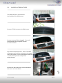
Download BMW E66 Specifications
Transcript
usbLOGiC USB-AV-Player USB-E65 for BMW E65 Professional navigation systems with 8.8” monitor Product features • USB-port for media up to 2 TB (2000GB) • supports FAT32 and NTFS formatted media • multi partition capable • compatible with MP3, AVI, VOB, MOV, RMVB, JPG and many more • last position memory • integrated into and controllable by vehicle infotainment • AV-input with IR-control channel • control of after-market devices by OEM buttons, e.g. DVD-player, USB/iPod devices, … • after-market rear-view camera input • automatic switching to rear-view camera input (only from usbLOGiC mode) • rear-view camera power (+12V max 1A) • rear-seat-entertainment AV-output • optional remote control for full USB functions/rear-seat-entertainment • power on remote out trigger signal (+12V max 1A) to switch on connected devices • video-in-motion Version 31.01.2013 USB-E65 Contents 1. Prior to Installation 1.1. 1.2. 1.3. 1.4. 1.4.1. 1.4.2. Delivery contents Check compatibility of vehicle and accessories Setting the dip switches of the CAN-box TV-436 Setting the dip switches of the USB-box USBC-M536 Automatic switching to rear-view camera Deactivating usbLOGiC AV input 2. Installation 2.1. 2.2. 2.3. 2.4. 2.4.1. 2.4.2. 2.4.3. 2.4.4. 2.4.5. Installation of CAN-box TV-436 Installation of USB-box USBC-M536 Antennas and optional IR-remote control set Connecting peripheral devices AV-source Installing AV-source’s IR-sensor additionally After-market rear-view camera After-market rear-seat-entertainment Factory nightvision, factory DVD-changer, factory rear-view camera 3. Operation 3.1. 3.2. 3.3. 3.4. 3.5. Activation of the video-in-motion function Selecting the usbLOGiC as current AV-source Assigning device control for connected AV-source Switching to internal USB, AV-source or after-market rear-view camera Button assignment table iDrive 4. Specifications 5. Connections (USB-box) 6. Technical support Page 1 Appendix A – Device control table Appendix B – USB function manual Version 31.01.2013 USB-E65 Legal Information By law, watching moving pictures while driving is prohibited, the driver must not be distracted. We do not accept any liability for material damage or personal injury resulting, directly or indirectly, from installation or operation of this product. This product should only be used while standing or to display fixed menus or rear-view-camera video when the vehicle is moving, for example the MP3 menu for DVD upgrades. Changes/updates of the vehicle’s software can cause malfunctions of the interface. We offer free software-updates for our interfaces for one year after purchase. To receive a free update, the interface must be sent in at own cost. Labor cost for and other expenses involved with the software-updates will not be refunded. 1. Prior to installation Read the manual prior to installation. Technical knowledge is necessary for installation. The place of installation must be free of moisture and away from heat sources. 1.1. Delivery contents Take down the SW-version and HW-version of the interface boxes, and store this manual for support purposes. Harness Harness CAN-box TV-436 HW_____ SW _____ C2C-BMW02 TV-BMW65 Harness C3C-AVIR USB-box USBC-M536 HW_____ SW_____ USB-installation socket USBC-EXT If remote function for a peripheral device shall be used, additional an IR. Page 2 Remote cable and Y-adapter are needed, see chapter AV-source Version 31.01.2013 USB-E65 1.2. Check compatibility of vehicle and accessories Requirements Vehicle 7series (E65/E66) Navigation Navigation system Professional E65 (older 1/2-button iDrive or CIC (newer 8-button iDrive) with 8.8” monitor Limitations factory-TV-tuner Must NOT be installed. If uninstalled, optical ring must be closed. factory DVD-changer or factory nightvision After-market rear-view camera cannot be connected to the usbLOGiC interface. factory rear-seat-entertainment Additional interface VL-RGB02-R is necessary After-market rear-view cam Only works from usbLOGiC mode, not from OEM. USB-port Only for media which work with power supply by ONE single USB connector Factory PDC If an after-market rear-view camera should be connected by the usbLOGiC the visual PDC display must be deactivated occasionally or permanently for camera picture. 1.3. Setting the dip switches of the CAN-box TV-436 All vehicles 1.4. dip 1 ON, dip 2 OFF, dip 3 OFF Setting the dip switches of the USB-box USBC-M536 The default dip switch settings of the USB-box need to be changed ONLY if a rear-view camera is or shall be connected or if the AV-input of the usbLOGiC shall be deactivated. The dip switches are located inside the USB-box. For changes it is necessary to open the box. Default settings are: Page 3 dip1 = ON, dip2 = OFF, dip3 = ON Version 31.01.2013 USB-E65 1.4.1. Automatic switching to rear-view camera If an after-market rear-view camera shall be connected or a factory rear-view camera is connected, in order for the usbLOGiC to automatically switch to its camera input, when reverse is engaged set dip2 = ON (up). Dip switches of USB-box Note: Automatic switching works only from usbLOGiC mode. 1.4.2. Deactivating usbLOGiC AV input If no peripheral AV-source shall be connected to the usbLOGiC, we recommend to disable the AV-input, to avoid customers switching by mistake to black/no picture of the AV-input. In order to disable the AV-input of the usbLOGiC, set dip1 = OFF (down). dip switches of USB-box 2. Installation Switch off ignition and disconnect the vehicle’s battery! If according to factory rules disconnecting the battery has to be avoided, it is usually sufficient to put the vehicle in sleep-mode. In case the sleep-mode does not show success, disconnect the battery with a resistor lead. Complete and correct function of the interface is possible only when CAN and MOST® (tuner) connections are made properly. On vehicles without TV-icon, it will be coded automatically after installation. Place of installation is at the rear of the navigation screen and at the rear of the navigation computer. Page 4 Note: The loose white and green cable of harness TV-BMW65 are not required and must be isolated. Version 31.01.2013 USB-E65 2.1. Installation of CAN-box TV-436 The CAN interface is connected to the backside of the OEM screen. Remove 3 TORX screws at the OEM screen. Remove cover grill (only plugged). Place soft towel beneath the navigation monitor to avoid scratches Flip down the board monitor. NOTE: The OEM screen gets stuck with its connector at the upper side of the cockpit. Insert a hard plastic sheet like a credit card to prevent cockpit from taking damage. Page 5 Remove the black connector at the backside of the screen as shown below. Version 31.01.2013 USB-E65 
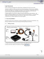
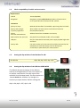
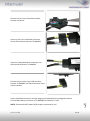
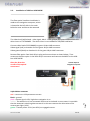
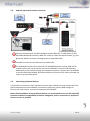
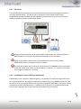
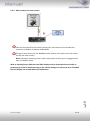
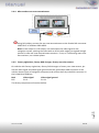
Remove 12-pin insert from black vehicle harness connector. Insert 12-pin insert into black connector of the CAN interface harness TV-BMW65. Insert the completed black connector into CAN interface harness TV-BMW65. Connect 12-pin insert from CAN interface harness TV-BMW65 into black connector from vehicle harness. 6 Insert completed connector into the plug on the backside of the navigation monitor. Connect 8pin Molex connector of TV-BMW65 to CAN-box TV-436. Version 31.01.2013 Page NOTE: Pictures do NOT show the fibre optics connected in car! USB-E65 2.2. Installation of USB-box USBC-M536 The fibre optical interface installation is made at the navigation computer, which is located at the left side in the trunk behind a cover and has to be removed. The video lead (red/colored - video signal, black - video ground) has to be removed from the white insert of C2C-BMW02. The white insert is not needed for E65/E66 installation. Connect video lead of C2C-BMW02 to green 18-pin AMP connector Video-signal (red) to chamber 3 of the green 18-pin AMP connector Video-ground (black) to chamber 11 of the green 18-pin AMP connector Remove fibre optics from black 20-pin plug and connect them as shown below. Then reconnect the fibre optics in the black 20-pin connector and connect the MOST to the USBbox USBC-M536. Obey the direction arrows of the optical connectors! To black 20pin of navigation computer Version 31.01.2013 USB-E65 Page red – connect to +12V permanent current black – ground pink – remote signal +12V, high when navigation is on white – The white wire is not connected and has to be isolated. In some cases it is possible that the automatic switching does not work. In this case connect the white wire to the reverse gear light (+12V). green – camera power +12V (max 0.5A) on engaged reverse. 7 14pin Molex connector 2.3. USB and optional IR-remote control set Connect USB-connector of USB-installation socket USBC-EXT to USB-socket of USBbox USBC-M536 and install the USBC-EXT socket in a well accessible location, e.g. the glove-box. Make sure there is enough space to load USB-media. Installation socket for the connection of USB-media. The USB-IRSET consists of the external C3C-SENSOR IR-sensor and the USBC-RC IRremote control and can be used to control the usbLOGiC’s internal USB functions additionally to the control through the navigations buttons. Connect the C3C-SENSOR to the female black/red/blue 3pin AMP connector of harness C3C-AVIR and locate the sensor in an accessible place. 2.4. Connecting peripheral devices It is possible to connect an after-market AV-source, after-market rear-view camera and rearseat-entertainment to the usbLOGiC. Also factory nightvision, factory DVD-changer or factory rear-view camera must be connected to the usbLOGiC. Page 8 Before final installation of the peripheral devices, we recommend to test-run the usbLOGiC functions to detect incompatibility of vehicle, navigation, factory accessories or peripheral devices as soon as possible. Version 31.01.2013 USB-E65 2.4.1. AV-source The usbLOGiC has the possibility to connect and remotely control by navigation buttons a pre-programmed device. The device list in the device control table shows the preprogrammed remote channels and the related IR-remote cables STA-xxx which must be ordered separately for the control of the device. Using the respective STA-xxx IR-control cable, interconnect the yellow female 3pin AMP connector of harness C3C-AVIR and the IR-port of the AV-source. Using an RCA-cable, interconnect the female RCA-port AV1 of the USB-box USBC-M536 with the AV-output of the AV-source. The pink ACC-output wire (+12V max 1A) of harness C2C-BMW02 can be connected to the ACC-input wires of the connected device to switch it on. It carries +12V when the navigation computer is running. 2.4.2. Installing AV-source’s IR-sensor additionally Page 9 Additionally to the control via OEM navigation, it is possible to install the original IR-sensor of a connected device. By using the respective Y-adapter (e.g. STA-Y35MM or STA-RJ12) for the IR-Port of the connected device, the controls of navigation AND device’s IR-sensor can be connected and used simultaneously. Installation of the IR-sensor is recommended as the controls via navigation are limited, and not all functions may be covered. Version 31.01.2013 USB-E65 2.4.3. After-market rear-view camera Connect the video RCA of the after-market rear-view camera to the female RCA connector R-CAM IN of USB-box USBC-M536. The green wire of harness C2C-BMW02 can be used as +12V power (max 1A) supply for the rear-view camera. Note: Automatic switching to the camera-input when reverse gear is engaged works only in usbLOGiC mode. Page 10 With an existing factory PDC the visual PDC display must be deactivated occasionally or permanently by iDrive while operating in the vehicle settings for camera picture. If needed the PDC display can be switched on by PDC button. Version 31.01.2013 USB-E65 2.4.4. After-market rear-seat-entertainment Using RCA-cables, connect the rear-seat-entertainment to the female RCA-connector VIDEO OUT of USB-box USBC-M536. Note: As the output is a full output, not shared with the video signal for the navigation system, splitting the video with an RCA Y-cable might give a good enough picture for two rear-seat-entertainment monitors. If not, or if connecting more than two monitors, use a video splitter. 2.4.5. Factory nightvision, factory DVD-changer, factory rear-view camera On vehicles with factory nightvision, factory DVD-changer or factory rear-view camera, pin out the video-signal and video-signal ground from the green 18pin AMP connector of the vehicles harness (rear of navigation computer) and connect them by male RCA-connector to the R-CAM IN of USB-box. Navi E65 Video-signal Pin 3 Video-signal ground Pin 11 Page 11 The factory component will work as before. Version 31.01.2013 USB-E65 3. Operation 3.1. Activation of the video-in-motion function Tthe video-in-motion function is permanently active without disturbing the navigation performance. 3.2. Selecting the usbLOGiC as current AV-source In the vehicle’s main menu, select Infotainment and then TV by iDrive to choose the usbLOGiC as current AV-source. 3.3. Assigning device control for connected AV-source After selecting the usbLOGiC as current AV source, push iDrive knob to open the usbLOGiC control menu. Select control levels setup “AV: RCxx” and assign related IR-code as described in device control table. Note: If the AV-input is deactivated (see chapter “Deactivating usbLOGiC AV-input”), the menu items “AV” and “AV: RCxx” will not be available. 3.4. Switching to internal USB, AV-source or after-market rear-view camera Page 12 In the usbLOGiC control menu, choose TV to enter internal USB mode, AV to enter AV-input mode (not available if AV-input is deactivated, see chapter “Deactivating usbLOGiC AVinput”) or REAR CAM to switch to the usbLOGiC after-market rear-view camera-input (even if the automatic switching to the camera input is disabled, see chapter “Automatic switching to rear-view camera”). After selection the menu will close automatically and switch to the selected source. The iDrive knob, some multi-function-steering wheel buttons (MFSW) and some navigation buttons (HU) are now available for remote functions (see assignment table for iDrive below). By pressing the iDrive-MENU-button, the system returns to the factory iDrive functions. By pressing the iDrive knob again, the usbLOGiC control menu will be re-entered. Version 31.01.2013 USB-E65 3.5. Button assignment table iDrive The button assignment table shows which functions of usbLOGiC and additionally connected devices can be executed by iDrive. Once USB or AV-input mode are activated the iDrive action in the left column will execute the function described in the corresponding device column. The function description equals the remote control buttons of the optional usbLOGiC remote control or the additional device. On the additional device the writing may vary (e.g. AV instead of Source). iDrive Action Internal USB DVB-T Tuners Device DVD on AV-input DVC on AV-input MENU long MENU short SETUP Return to factory iDrive functions MENU Return to factory iDrive functions Setup Return to factory iDrive functions Setup Return to factory iDrive functions OPTIONS long *2 OPTIONS short *2 SOURCE INFO Audio Audio Signal strength Subtitle Subtitle ENTER long ENTER short NORTH long NORTH short WEST long WEST short SOUTH long SOUTH short POWER OK / PLAY EXIT UP MEDIA LEFT DOWN POWER OK EPG UP EXIT LEFT SOURCE DOWN Power OK Menu/PBC *1 Up Play/Resume Left Source Down Power OK Menu/PBC *1 Up Play/Resume Left Source Down Power OK Shuffle Previous chapter Play/resume Left Source Next chapter EAST long POWER AUTO Zoom EAST short Left turn Right turn UP long on MFSW *3 UP short on MFSW *3 RIGHT Previous Track Next Track RIGHT Previous channel Next channel SOURCE Right Previous chapter Next chapter Next DVD Previous Track Previous channel Previous chapter Next DVD or DVD selection menu Right Previous chapter Next chapter Next DVD or DVD selection menu Previous chapter KCE: increase vol, Vlink: ESC Right Up Down Next DVD or DVD selection menu Previous chapter DOWN long on MFSW *3 DOWN short on MFSW *3 SOURCE INFO Next DVD Next Track Next channel Next chapter Next DVD or DVD selection menu Next chapter Next DVD or DVD selection menu Next chapter SOURCE Next DVD Previous channel Previous chapter Next DVD or DVD selection menu Previous chapter Next DVD or DVD selection menu Previous chapter RIGHT long SOURCE INFO Next DVD Next DVD or DVD on HU *3 selection menu RIGHT short Next Track Next channel Next chapter Next chapter on HU *3 *1 DVD title menu *2 not available on all vehicles *3 multi function steering wheel and head-unit Next DVD or DVD selection menu Next chapter Previous Track KCE: Light Bulb, Vlink: Subtitle KCE: lower vol, Vlink: Display Page 13 LEFT long on HU *3 LEFT short on HU *3 iPod interface on AVimput Setup Return to factory iDrive functions Version 31.01.2013 USB-E65 4. Specifications Operation voltage Stand-by power drain Operation power drain Power consumption Power rating USB-port Temperature range Weight Measurements (box only) B x H x T 10.5 – 14.8V DC <1mA min. 400mA/max. 900mA min. 5.5W/max. 12.4W 0,5A permanent (0,8A max) -30°C to +80°C 312g 135 x 30 x 105 mm 5. Connections (USB-box) 6. Technical Support Caraudio-Systems Vertriebs GmbH manufacturer/distribution Rheinhorststr. 22 D-67071 Ludwigshafen am Rhein NavLinkz GmbH corporate sales/tech dealer-support Eurotec-Ring 45 D-47445 Moers phone +49 180 3 907050 email [email protected] Page 14 Legal disclaimer: Mentioned company and trademarks, as well as product names/codes are registered trademarks ® of their corresponding legal owners. Version 31.01.2013 USB-E65