1
Inventory continued
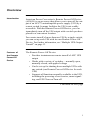
UPS-side view of
the Remote
Power-Off unit:
Figure 2
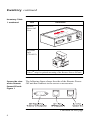
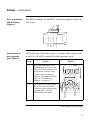
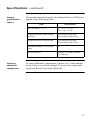
The following figure shows the side of the Remote PowerOff unit that connects to the UPS.
1 2 3 4
Configuration
DIP Switches
DB9 Male Port –
To UPS
Figure 2:UPS-side view of the Remote Power-Off unit
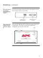
Top view of the
Remote PowerOff unit: Figure
3
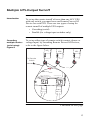
The top of the Remote Power-Off unit is shown in the following figure. The labels on the decal identify the
components on the sides of the unit.
LED
CONFIGURATION
TO UPS
POWER-OFF
/ TEST
w w w. a p c c . c o m
AP9830
UPS REMOTE POWER-OFF DEVICE
TO SERVER OR
ACCESSORIES
RPO / CASCADE IN
CASCADE OUT
Figure 3:Top view of the Remote Power-Off unit
5