1
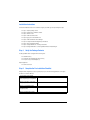
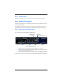
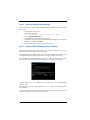
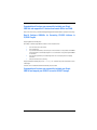
QUICK START GUIDE
[ Quick Start Guide ]
INTELLIGENT STORAGE ROUTER INSTALLATION d
Support Headquarters
QLogic Corporation
4601 Dean Lakes Blvd
Shakopee, MN 55379
USA
QLogic Web Site
www.qlogic.com
Technical Support Web Site
support.qlogic.com
Technical Support Email
[email protected]
Technical Training Email
[email protected]
North American Region
Email
[email protected]
Phone
+1 952-932-4040
Fax
+1 952-687-2504
Europe, Middle East, and Africa Region
Email
[email protected]
Phone Numbers by Language
+353 1 6924960 — English
+353 1 6924961 — Français
+353 1 6924962 — Deutsch
+353 1 6924963 — Español
+353 1 6924964 — Português
+353 1 6924965 — Italiano
Asia Pacific Region
Email
[email protected]
Phone Numbers by Language
+63-2-885-6712 — English
+63-2-885-6713 — Mandarin
+63-2-885-6714 — Japanese
+63-2-885-6715 — Korean
Latin and South America Region
Email
[email protected]
Phone Numbers by Language
+52 55 5278 7016 — English
+52 55 5278 7017 — Español
+52 55 5278 7015 — Português
Quick Start Guide
The iSR6142 Intelligent Storage Router provides remote and local SAN island connectivity. The major applications are:
❑
Remote Data Replications between Fibre Channel (FC) storage arrays
❑
Connecting remote FC Servers to local FC storage
❑
Connecting iSCSI Storage to FC storage area network (SAN)
❑
Allocating Resources (FC storage arrays, FC Virtual Tape Libraries, and FC tapes) from different SANs within
the data center to FC servers and/or iSCSI servers without worrying about E-port compatibility.
Suggested Configurations
Figure 1 connects local Array 1 to remote Array 2 and the Server from local SAN to Storage from a remote SAN.
Figure 1. Connect Remote SAN Islands
Figure 2 provisions FC storage from one SAN to an FC server on different SAN and/or provisions FC storage to iSCSI
Servers.
Figure 2. Connect Local SAN Islands and iSCSI Servers to Fibre Channel SAN
1
Installation Instructions
This Quick Start Guide describes how to install and configure your new QLogic router by following these steps:
❑
Step 1. Verify the package contents.
❑
Step 2. Complete the pre-installation checklist.
❑
Step 3. Mount the router.
❑
Step 4. Install the SFP transceivers.
❑
Step 5. Apply power to the iSR6142 router.
❑
Step 6. Install the SANsurfer® Router Manager.
❑
Step 7. Configure the iSR6142 management port IP address.
❑
Step 8. Run the Configuration Wizard.
❑
Step 9. Configure iSR6142s for connecting remote SANs.
❑
Step 10. Configure iSR6142s for connecting FC/iSCSI initiators to FC/iSCSI targets.
Step 1. Verify the Package Contents
The QLogic iSR6142 Router is shipped with the following items:
❑
iSR6142 Router (1)
❑
Small Form Factor Pluggable (SFP) transceivers (2)
❑
AC power cord (1) and serial adapter (1)
Optional equipment:
❑
Shelf for rack mount
Step 2. Complete the Pre-installation Checklist
During the initial configuration process, the system prompts you to enter the following parameters. Use the space
provided to record the IP addresses.
Symbolic Name of this iSR6142
Management port IP address, subnet
mask, and gateway (if not using DHCP)
iSCSI port 1 IP address, subnet mask,
and gateway (GE-1)
iSCSI port 1 iSN IP address (GE-1)
iSCSI port 2 IP address, subnet mask,
and gateway (GE-2)
iSCSI port 2 iSNS IP address (GE-2)
2
Step 3. Mount the Router
Place the router on a flat surface or mount it in a standard 19-inch Electronic Industries Association (EIA) rack.
Step 4. Install the SFP Transceivers
An SFP transceiver is required for each of the router’s FC ports that will be connected to a Fibre Channel device or switch.
SFPs are included in the package.
To install an SFP transceiver, insert the transceiver into the router port and press gently until it snaps in place. The
transceiver will fit only one way. If the transceiver does not install under gentle pressure, flip it over and try again.
Step 5. Apply Power to the iSR6142 Router
Figure 3 shows the location of the ports and LEDs on the iSR6142 Router.
MANAGEMENT PORT
10/1000 ETHERNET
FC
PORTS
ISCSI
PORTS
RS232
PORT
HEARTBEAT LED
INPUT POWER LED
SYSTEM FAULT LED
AC POWER
Figure 3. iSR6142 Ports and LEDs
1.
Attach the AC power cord to the iSR6142 Router and then to the wall outlet or power strip.
2.
Verify that the router’s input power LED is illuminated. The iSR6142 Router first runs its self-test, which
takes about one minute, then begins normal operation.
3.
Verify that the heartbeat LED is blinking (once per second) and that the system fault LED is not illuminated.
For installation details, diagnostics, and troubleshooting, see the iSR6142 Intelligent Storage Router Installation Guide.
3
Step 6. Install the SANsurfer Router Manager
Perform the following steps to install the SANsurfer iSCSI/FC Router Manager application from the QLogic website to
a PC workstation:
1.
Close all programs currently running.
2.
Go to the QLogic download site:
http://support.qlogic.com/support/drivers_software.aspx
3.
Select the Intelligent Storage Routers icon.
4.
Select iSR6142 in the product selection window and click Go.
5.
Under the product name column, select the link to the SANsurfer Router Manager for your operating system.
6.
Read the license agreement and click Agree.
7.
Follow the system prompts to uncompress and install the application.
Step 7. Configure iSR6142 Management Port IP Address
Connect the router’s 10/100 Ethernet port to your workstation using a switch or hub. Alternatively you may connect your
workstation directly to the router using an Ethernet crossover cable.
The iSR6142 management port’s default IP address is 10.0.0.1 subnet 255.0.0.0. Make sure the workstation connected
to the iSR6142 Router has Ethernet address 10.0.0.x, where x is other than 1 and subnet mask is 255.0.0.0.
From the workstation, open a command window and using a telnet session connect to iSR6142 using IP address 10.0.0.1.
Login as “guest” and use the password “password.” This will take you to a CLI prompt as shown in Figure 4.
Figure 4. QLogic Router Command Line Interface
Enter the CLI command admin start. Default password is “config.” Enter the set mgmt command at the QRouter
(admin) #> prompt.
Select the mode. We recommend you use static address. Select Option 0 (Static), enter the IP address, Subnet
Mask, and Gateway.
You will lose the connectivity of the telnet session at this time. If you want to continue using the CLI, restart the telnet
session with the IP address you just assigned to the management port.
4
You now have the management port configured with the appropriate IP address. Connect the management port cable
to your Ethernet network. Connect cables to GE1, GE2, FC 1, and FC 2 cables as shown in the configuration diagrams
(Figure 1/Figure 2).
Step 8. Run the Configuration Wizard
1.
Invoke the SANsurfer® Router Manager previously installed on the computer that will be used to manage
the iSR6142. You should see a display as shown in the following figures.
2.
Click the Connect button on the top left corner.
3.
Enter the IP address of the iSR6142 you want to configure.
4.
Click Yes to start the configuration wizard. The following screen appears:
5.
Enter the Symbolic Name for this router.
6.
Select each iSCSI Port and use the wizard to enter IP addresses for the iSCSI Port, and optionally, the IP
address of an iSNS Server.
7.
Save the changes; the default password is “config.”
8.
Copy the FC WWPN (World Wide Port Names) for both FC Ports.You will need these names to present
LUNS from your Storage subsystem.
FC 1 WWPN
FC 2 WWPN
9.
If you have an NTP server, enable the NTP Server option and enter the NTP Server information. This is on
the Information tab that displays when you select the iSR6142 router in the system tree view.
❑
To connect to remote SANs, continue with step 9.
❑
To connect FC/iSCSI initiators to FC/iSCSI targets, continue with step 10.
5
Step 9. Configure iSR6142s for Connecting Remote SANs
Configuration requirement:
❑
At least one FC Port of the iSR6142 should be connected to a FC SAN.
❑
It is recommended to use Fibre Channel World Wide Port name (WWPN) based zoning. Add each iSR6142
router’s FC WWPN to all zones in the FC switch to which it is connected. The FC switch zoning changes allow
the iSR6142 router to discover all devices in the FC SAN.
Additional requirement for remote SAN island connectivity:
❑
The iSCSI/GE port IP addresses of both local and remote routers must be set so that the routers are accessible
to each other.
❑
The management port IP address of both local and remote routers must be set so that the routers are accessible
to each other.
❑
It is recommended that you have installed SmartWrite™ feature (License) on each router.
Associate remote iSR6142 to local iSR6142:
Using the graphical user interface (GUI)
1.
Invoke SANsurfer™ Router Manager and connect to a local iSR6142 using management port IP address.
2.
Run the Add Remote Router Wizard by selecting its option from the Wizard drop-down menu:
a.
Enter the remote router management port IP address and click Next.
b.
Enter the local router password (default password is “config”) in the password dialog box.
c.
Enter the remote router password (default password is “config”) in the password dialog
box. The Status information screen displays the status of this operation.
Using the command line interface (CLI)
❑
Use the remotepeer add command to associate the local and remote routers.
❑
Use the show remotepeer command to display the list of remote routers.
Refer to the iSR6142 Command Line Interface (CLI) User’s Guide.
Import FC Devices from remote SAN to local SAN:
Using the graphical user interface (GUI)
Run the Map Remote Initiator/Target Wizard to establish connection between local and remote devices:
1.
Select the device to be mapped by expanding the router tree.
2.
Click Next to select the other device for this mapping. If SmartWrite™ licenses are enabled, the screen
shows the SmartWrite™ features.
3.
Enable SmartWrite.
4.
If round-trip latencies are greater than 50 ms or WAN line rate is DS-3 (4500Mb/Sec) or less, enable
compression.
5.
Except for mapping of tape devices, select load balancing.
6.
Confirm the summary of this change.
7.
Enter the local router’s password. The status screen displays the status of this operation.
Using the command line interface (CLI), run the remotemap add command.
6
Congratulations! You have now successfully installed your QLogic
iSR6142s and mapped the FC devices from remote SAN to local SAN.
Refer to "Performance Tuning" in the iSR6142 Intelligent Storage Router Installation Guide for optimal parameter settings.
Step 10. Configure iSR6142s for Connecting FC/iSCSI Initiators to
FC/iSCSI Targets
Using the graphical user interface (GUI)
Run the Map Local Initiator/Target Wizard to establish connection between devices:
1.
Select the initiator device (FC or iSCSI).
2.
Select a target device.
3.
If you selected an iSCSI initiator, select the FC port on which this initiator is to be presented. The FC WWPN
for this iSCSI initiator is automatically assigned. It is not recommended to change the assigned FC WWPN
for this initiator.
4.
Select the target presentation port and iSCSI target name. The screen displays the device mapping
information.
5.
Verify the information before confirming.
Using the command line interface (CLI), run the localmap add command to map an FC or iSCSI initiator to an FC
or iSCSI target.
For details, refer to the iSR6142 Command Line Interface (CLI) User’s Guide.
Congratulations! You have now successfully installed your QLogic
iSR6142 and mapped your iSCSI/FC servers to iSCSI/FC storage.
7
Troubleshooting and Technical Support
For technical support, visit our web site, support.qlogic.com, email us at [email protected], or call 952-932-4040.
Warranty
The QLogic iSR6142 Router comes with a standard one-year QLogic warranty, or as specified by other agreements.
Please check the QLogic Web site at www.qlogic.com for warranty details.
Regulatory Information (Preliminary)
The following sections contain a summary of EMC/EMI test specifications performed on the QLogic iSR6142 Router to
comply with radiated emission, radiated immunity, and product safety standards.
Safety Standards
UL60950 (USA)
CSG 22.2 No. 60950 (Canada)
EN 60950 (EC)
CB Scheme-IEC 60950
Harmonics
EN 61000-3-2
Immunity
EN 55024:1998
Emission Standards
FCC Part 15B Class A (USA)
VCCI Class A ITE (Japan)
ICES-03 Issue 3 (Canada)
EN55022 Level A (EC)
CISPR 22, Class A
8
Voltage Fluctuations
EN61000-3-3
Marking
FCC Part 15
UL (United States)
TUV (United States)
cUL (Canada)
cTUV (Canada)|
TUV Europe (Germany)
VCCI
CE
GOST
MIC
BSMI/RRL
© 2008 QLogic Corporation. QLogic, the QLogic logo, SmartWrite, and SANsurfer, are registered trademarks or
trademarks of QLogic Corporation. All other brands and product names are trademarks or registered trademarks of their
respective owners. Information supplied by QLogic is believed to be accurate and reliable. QLogic Corporation assumes
no responsibility for any errors in this brochure. QLogic Corporation reserves the right, without notice, to makes changes
in product design or specifications.
*SN0054544-00 A*
J
QLogic Corporation
949.389.6000
26650 Aliso Viejo Parkway
www.qlogic.com
Aliso Viejo, CA 92656
SN0054544-00 A