1
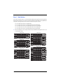
QUICK START GUIDE
[ Quick Start Guide ]
FIBRE CHANNEL SWITCH INSTALLATION
SANbox® 5000 Series
for Windows® Operating Systems
d
Purchasers of OEM products should consult with the OEM for support.
Support Headquarters
QLogic Corporation
12984 Valley View Road
Eden Prairie, Minnesota 55344-3657
USA
QLogic Web Site
www.qlogic.com
Technical Support Web Site
support.qlogic.com
Technical Support Email
[email protected]
Technical Training Email
[email protected]
North American Region
Email
[email protected]
Phone
+1-952-932-4040
Fax
+1 952-974-4910
Europe, Middle East, and Africa Region
Email
[email protected]
Phone Numbers by Language
+353 1 6924960
+353 1 6924961
+353 1 6924962
+353 1 6924963
+353 1 6924964
+353 1 6924965
- English
- Français
- Deutsch
- Español
- Português
- Italiano
Asia Pacific Region
Email
[email protected]
Phone Numbers by Language
+63-2-885-6712 - English
+63-2-885-6713 - (Mandarin)
+63-2-885-6714 - (Japanese)
+63-2-885-6715 - (Korean)
Latin and South America Region
Email
[email protected]
Phone Numbers by Language
+52 55 5278 7016 - English
+52 55 5278 7017 - Español
+52 55 5278 7015 - Português
Quick Start Guide
Installation Instructions
Congratulations on your purchase of the SANbox® 5000 Series Fibre Channel Switch. This guide describes the steps
to install and activate your new switch using a Windows® workstation. For advanced options and instructions (including
Solaris®, Linux®, and Mac OS X® installations), refer to the SANbox 5000 Series Fibre Channel Switch Installation
Guide on the product CD.
NOTE:
Do not apply power to the switch until instructed in Step 5.
Step 1. Verify the Package Contents
The SANbox 5000 Series Fibre Channel Switch is shipped with the following items:
1
1
2
4
2
1
1
SANbox 5000 Series Fibre Channel Switch
AC Power cord (5600)
AC Power cords (5602)
Rubber feet
Mounting brackets (5600)
Mounting screws (5600)
Enterprise Fabric Suite 2007 CD (free 30-day trial)
NOTE:
Determine if your switch order included Small Form Factor Pluggable (SFP) transceivers. If so, your switch
may come with 8, 12, or 16 SFPs depending on your switch configuration. If you ordered SFPs and XPAK switch stacking
cables separately, they will arrive in a different package. XPAK switch stacking cables connect SANbox 5000 Series
switches together through the XPAK ports. The switch must have a 20-port license to enable the XPAK ports, or you
must activate the 10-Gbps ports using the mPort Technology™ feature in Enterprise Fabric Suite 2007.
Step 2. Mount the Switch
❑
5600 Rack Mount with Brackets: Fasten the brackets to
the switch using 2 screws per bracket. Choose the
bracket holes to produce the desired set back. Place the
switch in a standard 19" rack and fasten each bracket to
the rack with two screws.
❑
Rack Mount with Rail Kit: Install the SANbox 3000/5000
rail kit in a standard 19" rack as described in the Rack
Mounting Guide.
A
L
L
A
L
A
16
A
L
17
A
L
18
A
L
19
A
1
Step 3. Stack Switches
If your switch is licensed for 20 ports, or you have activated the 10-Gbps ports using the mPort Technology feature in
Enterprise Fabric Suite 2007, you can connect up to six switches together through the 10-Gbps ports using XPAK switch
stacking cables. Stacking provides performance and fail-over while preserving ports for devices.
❑
❑
For a 2-switch stack, use two 3-inch stacking cables.
❑
For a 3-switch stack, use two 3-inch stacking cables and one 9-inch stacking cable.
❑
For a 4-switch stack, use three 3-inch stacking cables and three 9-inch stacking cables.
❑
For a 5-switch stack, use four 3-inch stacking cables and four 9-inch stacking cables.
❑
For a 6-switch stack, use two 3-inch stacking cables and six 9-inch stacking cables.
Remove the 10-Gbps port covers according to the instructions provided with the stacking cables. Connect 2, 3, 4,
5, or 6 switches into stacks.
2-SWITCH STACK
5-SWITCH STACK
3-SWITCH STACK
6-SWITCH STACK
4-SWITCH STACK
2
Step 4. Install Transceivers
An SFP transceiver is required for each switch port that will be connected to a device or another switch. The SANbox
5200 series switches support 1-Gbps and 2-Gbps transmission. The SANbox 5600 series switches support 1-Gbps,
2-Gbps, and 4-Gbps transmission.
❑
To install an SFP transceiver, insert the transceiver into the switch port and gently press until it snaps in place. The
transceiver will fit only one way. If the transceiver does not install under gentle pressure, flip it over and try again.
Step 5. Apply Power to the Switch
❑
❑
Attach the AC power cord(s) to the switch and wall
outlet or power strip. Verify that the Input Power LED
is illuminated.
The switch runs its self tests and begins normal
operation – this may take a few minutes. Verify that
the Heartbeat LED is blinking (once per second) and
the System Fault LED is NOT illuminated.
INPUT POWER
LED
HEARTBEAT
LED
SYSTEM
FAULT LED
Step 6. Verify Workstation Requirements
❑
❑
Verify that your workstation can support the QuickTools™ application with the following minimum requirements:
❑
Windows® 2003 SP1/SP2/R2 and XP
❑
256 MB memory minimum; 512 MB recommended
❑
1 GHz processor
❑
Video card with 256 colors
❑
CD ROM drive, RJ-45 Ethernet port
❑
Internet Browser: Microsoft® Internet Explorer® 5.0, Netscape Navigator® 6.0, Firefox 1.0, or Mozilla™ 1.5
❑
Java® 2 Standard Edition Runtime Environment 1.4.2
The default IP address of a new switch is 10.0.0.1. Ensure that your workstation is configured to communicate
with the 10.0.0 subnet.
Step 7. Connect the Workstation to the Switch
❑
Connect the workstation to the switch using an Ethernet crossover cable, switch, or hub. If you are using a Windows
workstation, you must have a live Ethernet connection when the workstation powers up.
3
Step 8. Log In to the Switch
You can log in to and manage the switch using the command line interface, the QuickTools web applet, or the optional
workstation-based application, Enterprise Fabric Suite 2007™. This guide will describe the use of QuickTools. For more
information about using Enterprise Fabric Suite 2007 under the 30-day trial license, see the SANbox 5000 Series Fibre
Channel Switch Installation Guide.
❑
Open an Internet browser and enter the default IP address 10.0.0.1 to start the QuickTools web applet.
❑
Log in to the switch using the default user name (admin) and password (password).
Step 9. Run the Configuration Wizard
❑
Obtain the IP address and subnet mask from your network administrator.
❑
Open the QuickTools Wizards menu and select Configuration Wizard. Follow the instructions to set network
parameters and the password. The default user name is admin; the default password is password. Changing the
IP address will terminate the QuickTools session.
❑
Open an Internet browser again and enter the new IP address to log in to switch.
Step 10. Connect Devices and Switches
❑
Connect fiber optic cables between the installed transceivers and their corresponding devices. Each port
auto-negotiates the proper port type with the connected device or switch.
Congratulations!
You have successfully installed your QLogic SANbox 5000 Series Switch!
4
© 2007 QLogic Corporation. QLogic, the QLogic logo, the Powered by QLogic logo, and SANbox are registered
trademarks or trademarks of QLogic Corporation. All other brands and product names are trademarks or registered
trademarks of their respective owners. Information supplied by QLogic is believed to be accurate and reliable. QLogic
Corporation assumes no responsibility for any errors in this brochure. QLogic Corporation reserves the right, without
notice, to makes changes in product design or specifications.
*50328-08
J
QLogic Corporation
949.389.6000
26650 Aliso Viejo Parkway
www.qlogic.com
A*
Aliso Viejo, CA 92656
50328-08 A