1
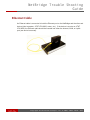
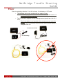
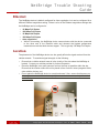
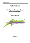
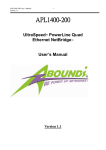
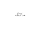
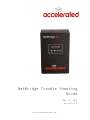
NetBridge Trouble Shooting Guide May 15, 2013 Version 4.0 www.acceleratedconcepts.com NetBridge Trouble Shooting Guide Contents Contents ............................................................................................................................ 2 Troubleshooting Tree ........................................................................................................ 3 Connections ...................................................................................................................... 4 USB modem ........................................................................................................................... 4 Ethernet Cable ....................................................................................................................... 5 Power .................................................................................................................................... 6 Ethernet ................................................................................................................................. 7 Location ............................................................................................................................ 7 Restore Default Settings .................................................................................................... 8 Start-‐up ............................................................................................................................. 9 LEDs .................................................................................................................................. 9 Known Issues ................................................................................................................... 11 Coin Cell Battery .................................................................................................................. 11 Technical Support ............................................................................................................ 12 2 of 12 Copyright Copyright Accelerated Concepts, Inc © 2008, 2009, 2010, 2011 NetBridge Trouble Shooting Guide Troubleshooting Tree 3 of 12 Copyright Copyright Accelerated Concepts, Inc © 2008, 2009, 2010, 2011 NetBridge Trouble Shooting Guide Connections If a NetBridge device is not working properly, first ensure that the unit has the proper connections. The following needs to be connected to the NetBridge: USB modem A supported USB modem must be inserted into either the internal or external USB port. A list of supported USB modems can be found at: http://acceleratedconcepts.com/support • The NetBridge device only operates with one USB modem at a time. Do not plug in a USB modem into both the USB ports! External USB Port Internal USB Port 4 of 12 Copyright Copyright Accelerated Concepts, Inc © 2008, 2009, 2010, 2011 NetBridge Trouble Shooting Guide Ethernet Cable An Ethernet cable is connected to both the Ethernet port on the NetBridge and the other end device (client computer, AT&T VPN 8200, router, etc.). If the device is a router or AT&T VPN 8200, the Ethernet cable should be inserted into either the Internet, WAN, or Uplink port (see device’s manual). 5 of 12 Copyright Copyright Accelerated Concepts, Inc © 2008, 2009, 2010, 2011 NetBridge Trouble Shooting Guide Power Power is supplied by either the 12-volt AC wall wart, 12-volt battery, or PoE cable. • • The NetBridge device only operates with one supply of power. o DO NOT supply power to the device with both the PoE cable and the 12volt battery/12-volt AC wall wart! The 12-volt battery supplied with the NetBridge device typically has a life of 2-3 hours. o The 12-volt battery is not intended to be a permanent power source for the unit. If the 12-volt battery is being utilized, ensure that the battery is charged before use. 12-volt AC wall wart 12-volt battery 6 of 12 Copyright Copyright Accelerated Concepts, Inc © 2008, 2009, 2010, 2011 NetBridge Trouble Shooting Guide Ethernet The NetBridge device is default configured for Auto-negotiation, but can be configured for a different Ethernet negotiation setting. Below is a list of the Ethernet negotiation settings that the NetBridge can be configured to. • • • • • 10 Mbps Full Duplex 100 Mbps Full Duplex 10 Mbps Half Duplex 100 Mbps Full Duplex Auto-negotiation While in this setting, the NetBridge device communicates with the device connected to the other end of the Ethernet cable and chooses the highest performance transmission mode that both devices support. This is typically 100 Mbps Full Duplex. Location The placement of the NetBridge device at a site greatly affects the signal received from the cellular network. To maximize signal strength, do the following: • • • 7 of 12 Copyright Ensure that a cellular network tower is in the vicinity of the site where the NetBridge is located. Contact your cellular provider for further information. Place the NetBridge in an open space as far from the floor as possible within the site. Ensure that the location where the unit is placed is free of electric noise (magnetic fields, other cellular devices, etc.) Do not place the NetBridge device in a metal enclosure! Also, ensure that there are no other wireless communication devices (cell phones, wireless routers, etc.) within 1 ft. of the NetBridge Copyright Accelerated Concepts, Inc © 2008, 2009, 2010, 2011 NetBridge Trouble Shooting Guide Restore Default Settings Restoring a NetBridge device to factory default settings will clear out the settings obtained from the NetBridge’s remote configuration and load the factory default settings. To restore a NetBridge device back to default settings, perform the following steps: 1. 2. 3. 4. Power off the NetBridge for at least two seconds. Remove all USB devices from the NetBridge. Use the four rubber feet screws to remove the case of the NetBridge. Power on the NetBridge and wait 30 seconds for the device to complete startup. a. Note: at this point the only light that should be illuminated is a red USB LED. 5. Press the “Default configuration” button located on the circuit board of the NetBridge. The default configuration button is located above the “Restart” button, next to the coin cell battery. 6. Once the Default configuration button is pressed, ensure that the USB and Wireless LEDs of the NetBridge are alternately flashing red and green. This indicates that the NetBridge is applying the default configuration. 7. Wait for the NetBridge to reboot and apply the changes. Once the USB LED illuminates red and all other lights are off, it is safe to power off the NetBridge, reattach the case, and reconnect any USB devices. 8 of 12 Copyright Copyright Accelerated Concepts, Inc © 2008, 2009, 2010, 2011 NetBridge Trouble Shooting Guide Start-‐up The NetBridge device is configured to go through a specific start-up sequence, as detailed below. 1. Immediately upon powering on, the USB LED will illuminate YELLOW, verifying that power is being delivered to the NetBridge. The USB LED should immediately turn BLUE for two seconds, YELLOW for one second, GREEN for one second, and settle on RED. This indicates that the NetBridge successfully booted up and is waiting for the USB modem to be initialized (if connected). 2. Approximately 10 seconds after power up, the USB, Wireless, and signal strength LEDs will illuminate in a pattern corresponding to the LEDs section of this Troubleshooting Guide. LEDs The NetBridge has lights on the front panel that help an installer or end user to discern the current status. The USB and Wireless LEDs are labeled; the bars outlined in orange are the signal strength indicator. These lights usually indicate the state of their respective subsystems. Some light patterns represent the whole system state instead of a subsystem. The icons in the chart represent the state of the lights. Black ( ) indicates an off light. White ( ) indicates that the light is irrelevant in a pattern – these continue to show their own subsystem status. Multicolored symbols indicate a changing light. Examples: The Wireless light blinks red/off/green/off. The other lights can be any color. The Wireless light flashes amber twice. The other lights can be any color. The USB and Wireless lights are blinking red/green in opposite order. 9 of 12 Copyright Copyright Accelerated Concepts, Inc © 2008, 2009, 2010, 2011 NetBridge Trouble Shooting Guide System Status Power is off Power is on; early bootstage Initializing hardware Initializing modem Downloading firmware (green bar moves downward) Reconfiguring USB Subsystem No modem or unsupported modem Modem detected 3G/Wireless Subsystem 2G network detected and connected 3G network detected and connected 4G network detected and connected Network detected, can’t connect Cannot determine between 4G/3G/2G Cannot detect network Network detected, unable to register (check SIM ctard) Connecting o network (first try) Connecting to network (second try) Connecting to network (third try) Signal Strength 10 of 12 Signal strength Copyright Accelerated Concepts, Inc © 2008, 2009, 2010, 2011 NetBridge Trouble Shooting Guide Known Issues The NetBridge has the following known issues: Coin Cell Battery The NetBridge’s internal clock is powered by the coin cell battery located on the circuit board of the device. If this battery is damaged or dies, this will cause an error in the system where the NetBridge’s internal clock is unusable. This causes the NetBridge to freeze during boot. The following process can be used to determine if this issue is present: 1. Power on the NetBridge. 2. Watch the USB LED of the NetBridge. If the internal clock of the NetBridge is unusable, the USB LED will continuously loop, displaying a pattern of illuminating yellow, blue, yellow, green; meanwhile, all other LEDs of the NetBridge will remain off. To resolve this issue, perform the following steps: 1. Power off the NetBridge. 2. Use the four rubber feet screws to remove the case of the NetBridge. 3. Remove the coin cell battery from the battery holder located on the NetBridge circuit board next to the Restart and Default configuration buttons. 4. (Optional) Insert a new 3V coin cell battery into the NetBridge. a. Note: If a working coin cell battery is not connected to the NetBridge, it will not be able to save its date/time over reboots. However, this will not affect overall performance, so it is safe to leave the coin cell battery out. 5. Re-attach the NetBridge case. 6. Power the NetBridge on and verify that it boots properly. 11 of 12 Copyright Accelerated Concepts, Inc © 2008, 2009, 2010, 2011 NetBridge Trouble Shooting Guide Technical Support If you are having problems installing any of our products and need technical assistance, please call or email our help desk. • • • [email protected] +1 (813) 699-0295 Support hours are 9am to 5pm EST Corporate and Sales Headquarters Accelerated Concepts 1208 E Kennedy Blvd Suite 226 Tampa, FL 33602 Phone: +1 (813) 983-‐7635 [email protected] www.acceleratedconcepts.com 12 of 12 Copyright Accelerated Concepts, Inc © 2008, 2009, 2010, 2011