1
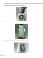
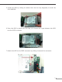
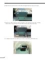
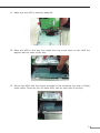
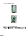
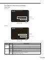
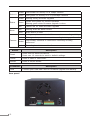
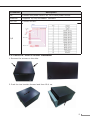
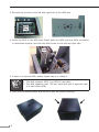
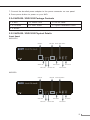
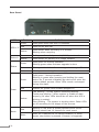
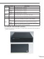
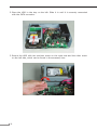
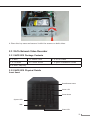
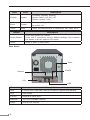
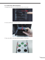
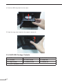
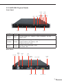
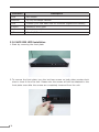
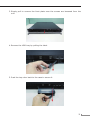
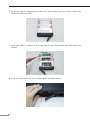
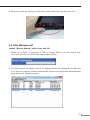
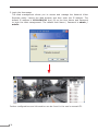
4/8/16/32-Ch Network Video Recorder NVR Series Quick Installation Guide Table of Contents Chapter 1. Introduction..................................................................................... 3 1.1 Before Installation................................................................................ 3 Chapter 2. Physical Description and Installation................................................... 4 2.1 4-Ch Network Video Recorder................................................................ 4 2.1.1 NVR-420 Package Contents.......................................................... 4 2.1.2 NVR-420 Physical Details............................................................. 4 2.1.3 NVR-420 HDD Installation............................................................ 5 2.2 8/16-Ch Network Video Recorder..........................................................10 2.2.1 NVR-810 / NVR-1610 Package Contents.......................................10 2.2.2 NVR-810 / NVR-1610 Physical Details..........................................11 2.2.3 NVR-810 / NVR-1610 HDD Installation.........................................13 2.2.4 NVR-820 / NVR-1620 Package Contents.......................................15 2.2.5 NVR-820 / NVR-1620 Physical Details..........................................15 2.2.6 NVR-820 / NVR-1620 HDD Installation.........................................17 2.3 32-Ch Network Video Recorder.............................................................19 2.3.1 NVR-3210 Package Contents.......................................................19 2.3.2 NVR-3210 Physical Details...........................................................19 2.3.3 NVR-3210 HDD Installation.........................................................21 2.3.4 NVR-3250 Package Contents.......................................................22 2.3.5 NVR-3250 Physical Details...........................................................23 2.3.6 NVR-3250 HDD Installation.........................................................24 2.4 Web Management................................................................................27 Chapter 1. Introduction Thank you for purchasing PLANET 4/8/16/32-Ch Network Video Recorder. The Network Video Recorder is designed for use within a surveillance system, and performs recordings and playbacks pictures from network cameras in the system. It is a recording device using a hard disk drive to record camera pictures instead of using video tapes so that pictures recorded by repeated overwriting will not experience deterioration of the recorded picture quality. Up to 4 (for NVR-420), 8 (for NVR-810 and NVR-820), 16 (for NVR-1610 and NVR-1620) and 32 (for NVR3210 and NVR-3250) cameras can be connected via a network and it is possible to record their camera pictures. It is possible to perform the settings or operate the NVR using a web browser installed on a PC connected to a network, or remote controller. Recorded video can be played back from remote site by a PC. Up to 4 PCs (web browsers) can access this unit concurrently and it is possible to perform the settings and operate this unit. The NVR is compatible with most major brand cameras and its ability to automatically search and find the available cameras on the network can greatly reduce the user effort when expanding the system. 1.1 Before Installation Before installation, please be sure to read this quick installation guide and user’s manual (CD) carefully to complete machine installation. This guide shows how to quickly set up the NVR. 3 Chapter 2. Physical Description and Installation 2.1 4-Ch Network Video Recorder 2.1.1 NVR-420 Package Contents 1 x NVR 1 x Power Cord 1 x Power Adapter 1 x RJ-45 Cable 1 x CD-ROM 8 x HDD Screw 1 x Remote Controller 1 x Quick Installation Guide 2.1.2 NVR-420 Physical Details Power LED HDD1 LED HDD2 LED System Fan Channel LED USB Connector Reset Button Remote Control IR Receiver Composite Audio HDMI Connector Composite Video Ethernet USB Connector LEDs Power 4 Power Connector Color Description Green When NVR-420 is fully started Red When NVR-420 is off, but power cord remains plugged in Amber Blinking during system initialization, reboot, and firmware upgrade Off When NVR-420 is off and the power cord is not plugged in HDD1/2 Channel 1~4 Green Disk is online Red Disk error Amber Solid amber when NVR-420 is recording Blinking amber when the disk is recycling Off No disk or disk is offline Green Solid green when NVR-420 is online Blinking during event triggered Off Disconnect or no camera is configured Connector Description USB Connect your USB flash disk for firmware upgrade and backup Reset Press and hold reset button for 30 seconds to factory default HDMI HDMI output Ethernet 10/100Mbps network 2.1.3 NVR-420 HDD Installation 1.Locate the screws highlighted below on the back of the NVR. 5 2.Use a Philips screw driver to release the screws. 3.Slide open the case as shown below. 4.One side of the housing can be detached as shown below. 6 5.Install the HDD by sliding its bottom first into the tray diagonally to avoid the tray separator. 6.Once the HDD is placed into the tray, you should see a gap between the HDD and the SATA connector. 7.Attach the HDD to the SATA connector by sliding it towards the connector. 7 8.Make sure the screw holes on the HDD are aligned with the ones on the tray. 9.Secure the HDD with the screws provided in the accessory box with a Philips screw driver. There are four for each HDD; two for each side of the tray. 10. Install the top HDD by attaching it to the corresponding SATA cable first. 8 11. Make sure the HDD is securely attached. 12. Place the HDD to the tray and make sure the screw holes on the HDD are aligned with the ones on the tray. 13. Secure the HDD with the screws provided in the accessory box with a Philips screw driver. There are four for each HDD; two for each side of the tray. 9 14. Slide the side housing back to the unit. 15. Secure the housing with the screws highlighted below. 2.2 8/16-Ch Network Video Recorder 2.2.1 NVR-810 / NVR-1610 Package Contents 1 x NVR 1 x Power Cord 1 x RJ-45 Cable 1 x CD-ROM 2 x HDD Screw 1 x Quick Installation Guide 10 2.2.2 NVR-810 / NVR-1610 Physical Details Front Panel NVR-1610 Network Video Recorder 1 2 3 4 5 6 7 8 9 10 11 12 13 14 15 16 HDD2 Alarm Power NVR-1610 Reset Power Status Network HDD1 IP Camera Status LED NVR Status LEDs Buzzer Reset Power Buzzer Button Button Button USB Port NVR-810 Network Video Recorder 1 2 3 4 Power NVR-810 Reset Power Reset Power Button Button LEDs Power HDD1/2 5 6 Status Network HDD1 7 8 HDD2 Alarm IP Camera Status LED NVR Status LEDs Buzzer Buzzer Button Color USB Port Description Green Normal operation Red System off (power adapter remains plugged in) Amber Blinking amber indicates device is initializing Green Solid green when the hard disk is mounted and being accessed Red Solid red for disk fail Amber Solid amber when disk is recording Blinking when recycling 11 Network Status Alarm Camera Amber Solid amber for activity on a 1Gbps network Green Solid green for activity on a 10/100Mbps network Amber Blinking during firmware upgrade Green Shows solid green for normal operation Blinking green when firmware upgrade is done Red Flashes red for failed firmware upgrade Red Blinking when an alarm occurs None When alarm is reset Green Solid green, live connected with no event or recording activity Amber Blinking amber, manual or event recording is being performed Amber Solid amber, schedule or continuous recording is being performed Red Recording is set but no video from camera Button Description Reset Press once to reset this device. Press over 10 seconds to reset to default settings. Power Press to start or shut down. Buzzer Press to on/off buzzer. Connector USB Rear panel 12 Description Connect your USB flash disk for firmware upgrade and backup. Connector Description AC Connect the power cord to AC 100~240V power source. Ethernet Supports 10/100/1000Base-T interface. RS-232 Connect to UPS. I/O 2.2.3 NVR-810 / NVR-1610 HDD Installation 1.Remove the screws on the side. 2.Push the top housing forward and then lift it up. 13 3.Remove the screws on the left and right side of the HDD tray. HDD Tray 4.Insert the HDD in the HDD tray. Please push the HDD until the SATA connection is connected properly, and lock the HDD screw on the left and right side. HDD 5.If there is a second HDD, please repeat step 4 to install it. Note 1. The NVR supports SATA I or SATA II hard disks 2. The NVR supports max. 3TB per hard disk and it supports total of 2 hard disks (6TB) 6.Place the top housing back and secure it with the bottom housing. 14 7.Connect the bundled power adapter to the power connector on rear panel. 8.Press power button to power on your NVR. 2.2.4 NVR-820 / NVR-1620 Package Contents 1 x NVR 1 x Power Cord 1 x RJ-45 Cable 1 x CD-ROM 6 x HDD Screw 1 x Quick Installation Guide 1 x Mouse 2.2.5 NVR-820 / NVR-1620 Physical Details Front Panel NVR-1620 USB Port Status LED Alarm LED HDD LED Buzzer Stop Button Reset Button Network LED IR Receiver Power Button NVR-820 USB Port Status LED Alarm LED HDD LED Buzzer Stop Button Reset Button Network LED IR Receiver Power Button 15 Rear Panel LEDs HDD x 2 Network Status Power Status Green Solid green when the HDD is mounted Red Solid red for disk fail Amber Solid amber when recording is in process Blinking when recycling Green Solid green for activity on a 10/100Mbps network Amber Solid amber for activity on a 1Gbps network Green Solid green for normal operation Blinking green when firmware upgrade is done Red Blinking red for failed firmware upgrade through USB disk Amber Blinking amber during firmware upgrade Green Solid green - Normal operation Blinking in green after pressing and holding the reset button for 5 seconds indicating the device will enter the restore default process. Other LEDs remain unchanged during this state. Red System off (power cord remains plugged in) Amber Fast blinking - During system initializing/starting. Continuous blinking - When system is unable to start properly (All other LEDs should be off when this LED is blinking in amber) Slow blinking - The system is shutting down. Other LEDs go off according to the stages of the process. Red Blinking in red when a system/camera event occurs. Blinking should last 10 seconds for each event None Goes off if reaches the 10-second duration, or when buzzer stop button is pressed (if buzzer is triggered) Alarm 16 Definitions Buttons Power Reset Buzzer Stop Buzzer Beep Status Definitions ON Press and hold for 2 seconds OFF Press and hold for 2 seconds Restore default Press and hold for 5 seconds Restart Press and hold for 2 seconds STOP Press and release to stop buzzer right away Status Definitions Complete start Beep once (indicating the system is fully started) Initiating restart Beep once (Indicating the restart process has begun) Initiating shutdown Beep once (Indicating users to release the Power button as the shutdown process has begun) 2.2.6 NVR-820 / NVR-1620 HDD Installation 1.Remove the screws on both sides (1 on each side) and remove the top case by pulling it toward you. 17 2.Place the HDD in the tray on the left. Slide it in until it is securely connected with the SATA connector. 3.Secure the HDD with the tool-less screw on the right side and the other screw on the left side, which can be found in the accessory box. 18 4.Place the top case and secure it with the screws on both sides. 2.3 32-Ch Network Video Recorder 2.3.1 NVR-3210 Package Contents 1 x NVR 1 x Power Cord 1 x RJ-45 Cable 1 x CD-ROM 12 x HDD Screw 1 x Quick Installation Guide 4 x HDD Tray Key 2.3.2 NVR-3210 Physical Details Front Panel Reset/Restart button Power LED Power Button System LED USB Event LED 19 LEDs Color Description System Amber Firmware upgrade: blinking System failure (AP fail): off System normal: solid Event Amber Event recording: solid No event: off Power Blue Power on/Restart/Reset to default/OS fail: stays solid Button Description Reset/Restart Press and release for restart. Press over 3 seconds to reset to default settings. Don't release the button until the system LED blinks. Power Press to start or shut down. Rear Panel Audio E-SATA Ethernet VGA USB Connector Description USB Connect your USB flash disk for firmware upgrade and backup. VGA VGA output E-SATA External E-SATA HDD Ethernet 10/100/1000Mbps network. Audio Line in/Line out/Mic 20 2.3.3 NVR-3210 HDD Installation 1.Release the HDD tray by pulling the lock to the right. 2.Pull the HDD tray out of the case. 3.Place the HDD in the tray and the bottom of the tray. 21 4.Put the HDD tray back to the case. 5.Push the tray door back to the case to secure it. 2.3.4 NVR-3250 Package Contents 1 x NVR 1 x Power Cord 1 x RJ-45 Cable 1 x CD-ROM 16 x HDD Screw 2 x Angle bar 4 x Angle Screw 4 x Handle Screw 2 x Handle kit 1 x Quick Installation Guide 22 2.3.5 NVR-3250 Physical Details Front Panel System LED USB1 HDD 1 LEDs HDD 2 USB2 Event LED HDD 3 Color Reset Button Power LED Power Button HDD 4 Description Power Blue During power on / restart / reset to default / OS fail: Stays solid System Amber During firmware upgrade: Blinking System failure (AP failure): Off System Normal: Solid Event Amber During event recording: Solid No event: Off Rear Panel AC Power Power Supply Fan System Fan VGA Output Gigabit Ethernet USB x 2 System Fan Line in/out/Mic. e-SATA DI x 8, DO x 4 23 Connector Description VGA VGA output Ethernet 10/100/1000Mbps network USB Connect your USB flash disk for firmware upgrade and backup E-SATA External E-SATA HDD Audio Line in/Line out/Mic I/O DI x 8 / DO x 4 2.3.6 NVR-3250 HDD Installation 1.Start by removing the front plate. 2.To remove the front plate, turn the tool-less screws on both sides counter-clock wise to loose it from the unit. Please note the screws will still be attached to the front plate even after the screws are completely loosened from the unit. 24 3.Simply pull to remove the front plate once the screws are loosened from the unit. 4.Remove the HDD tray by pulling the latch. 5.Push the tray door back to the case to secure it. 25 6.Once the tray is removed from the unit, notice there are four holes, which are used to secure the HDD. 7.Once the HDD is placed in the tray, flip it over and secure the HDD with the screws. 8.Push the tray back into the unit and push it all the way in. 26 9.Secure the tray by pushing in the latch, which locks the tray with the unit. 2.4 Web Management Install “Device Search” utility from the CD 1.Please go to Start Programs NVR Search NVR to run the search tool. Then you will see the utility start search the network. 2.The NVR should be located and its IP address should be displayed: Double-click on it and the program should automatically access the NVR’s web administration page from your default browser. 27 3.Login the Homepage The Web management allows you to access and manage the Network Video Recorder easily. Launch the Web browser and then enter the IP address. The default IP address is 192.168.0.20. And, fill up the User Name and Password to login the Web management. The default User Name / Password is admin / admin. Further configurations and information can be found in the user’s manual CD. 28