1
Hardware Installation Guide
PERPETUAL INNOVATION
Lenel OnGuard® 2010 Technology Update Hardware Installation Guide, product version 6.4
This guide is item number DOC-600, revision 1.071, May 2011
Copyright © 1997-2010 Lenel Systems International, Inc. Information in this document is subject to change without
notice. No part of this document may be reproduced or transmitted in any form or by any means, electronic or
mechanical, for any purpose, without the express written permission of Lenel Systems International, Inc.
Non-English versions of Lenel documents are offered as a service to our global audiences. We have attempted to
provide an accurate translation of the text, but the official text is the English text, and any differences in the
translation are not binding and have no legal effect.
The software described in this document is furnished under a license agreement and may only be used in accordance
with the terms of that agreement. Lenel and OnGuard are registered trademarks of Lenel Systems International, Inc.
Microsoft, Windows, Windows Server, and Windows Vista are either registered trademarks or trademarks of
Microsoft Corporation in the United States and/or other countries. Integral and FlashPoint are trademarks of Integral
Technologies, Inc. Crystal Reports for Windows is a trademark of Crystal Computer Services, Inc. Oracle is a
registered trademark of Oracle Corporation. Other product names mentioned in this User Guide may be trademarks or
registered trademarks of their respective companies and are hereby acknowledged.
Portions of this product were created using LEADTOOLS © 1991-2010 LEAD Technologies, Inc. ALL RIGHTS
RESERVED.
OnGuard includes ImageStream® Graphic Filters. Copyright © 1991-2010 Inso Corporation. All rights reserved.
ImageStream Graphic Filters and ImageStream are registered trademarks of Inso Corporation.
Warranty
Lenel warrants that the product is free from defects in material and workmanship under normal use and service with
proper maintenance for one year from the date of factory shipment. Lenel assumes no responsibility for products
damaged by improper handling, misuse, neglect, improper installation, over-voltages, repair, alteration, or accident.
This warranty is limited to the repair or replacement of the defective unit. In no event shall Lenel Systems
International be liable for loss of use or consequential damages of any kind, however occasioned.
There are no expressed warranties other than those set forth herein. Warranty expressly excludes third party additions,
deletions and/or upgrades to this product, including those contained herein. Lenel does not make, nor intends, nor
does it authorize any agent or representative to make any other warranties or implied warranties, and expressly
excludes and disclaims all implied warranties of merchantability or fitness for a particular purpose.
Returned units are repaired or replaced from a stock of reconditioned units. All returns must be accompanied by a
return authorization number (RMA) obtained from the Lenel customer service department prior to returning or
exchanging any product. The RMA number must appear on the outside of the shipping box and on the packing slip.
Any items returned without an RMA number will not be accepted and will be returned at the customer’s expense. All
returns must have transportation, insurance, and custom brokers’ fees prepaid.
Liability
It is expressly understood and agreed that the interface should only be used to control exits from areas where an
alternative method for exit is available. This product is not intended for, nor is rated for operation in life-critical
control applications. Lenel Systems International is not liable under any circumstances for loss or damage caused by
or partially caused by the misapplication or malfunction of the product. Lenel’s liability does not extend beyond the
purchase price of the product.
Hardware Installation Guide
Table of Contents
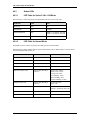
Hardware Installation Guidelines ....................................... 17
1. Inputs, Outputs and Interface Signals .................................................. 19
1.1 Power Inputs ....................................................................................................... 19
1.2 Alarm Inputs ....................................................................................................... 20
1.3 Reader Inputs/Outputs ....................................................................................... 20
1.4 Relay Outputs ..................................................................................................... 20
1.5 RS-485 Communication Overview ...................................................................... 20
1.6 RS-232 Interfaces ............................................................................................... 23
2. System Wiring and Other Considerations ............................................ 24
2.1 General Wiring Considerations ........................................................................... 24
2.2 Mounting ............................................................................................................. 29
2.3 Ground Wiring .................................................................................................... 36
2.4 Alarm Input Wiring .............................................................................................. 37
2.5 RS-485 Communication Wiring .......................................................................... 37
2.6 RS-232 Communication Wiring .......................................................................... 40
2.7 Weatherproofing ................................................................................................. 40
2.8 Relay Contact Protection .................................................................................... 41
3. System Turn-Up Considerations .......................................................... 43
3.1 Device Configuration Checks ............................................................................. 43
3.2 Ground Potential Difference Checks Before Connecting .................................... 44
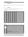
4. Maintenance ........................................................................................ 45
4.1 Firmware Updates .............................................................................................. 45
4.2 AES/Extended Firmware .................................................................................... 46
5. UL Certified Installations ...................................................................... 47
5.1 Power ................................................................................................................. 49
5.2 Typical Combinations for UL Installations ........................................................... 49
5.3 UL Requirements ................................................................................................ 52
5.4 Troubleshooting .................................................................................................. 54
LNL-500 Intelligent System Controller ............................... 57
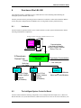
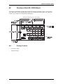
6. Overview of the LNL-500 ..................................................................... 59
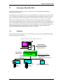
6.1 Interfaces ............................................................................................................ 59
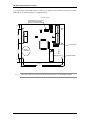
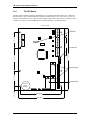
6.2 The Intelligent System Controller Board ............................................................. 59
7. Installation ............................................................................................ 61
revision 1 — 3
Table of Contents
7.1 Wiring ................................................................................................................. 61
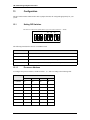
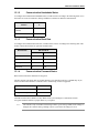
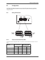
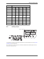
8. Configuration ....................................................................................... 67
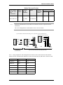
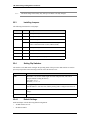
8.1 Setting DIP Switches .......................................................................................... 67
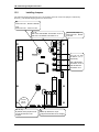
8.2 Installing Jumpers ............................................................................................... 69
9. Maintenance ........................................................................................ 70
9.1 Verification .......................................................................................................... 70
9.2 Replace Memory Backup Battery ....................................................................... 70
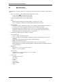
10. Specifications ..................................................................................... 71
LNL-1000 Intelligent System Controller ............................. 73
11. Overview of the LNL-1000 ................................................................. 75
11.1 Interfaces .......................................................................................................... 75
11.2 The ISC Board .................................................................................................. 76
12. Installation .......................................................................................... 77
12.1 Wiring ............................................................................................................... 77
13. Configuration ..................................................................................... 84
13.1 Setting DIP Switches ........................................................................................ 84
13.2 Installing Jumpers ............................................................................................. 86
14. Maintenance ...................................................................................... 89
14.1 Verification ........................................................................................................ 89
14.2 Replace Memory Backup Battery ..................................................................... 89
15. Specifications ..................................................................................... 90
LNL-2000 Intelligent System Controller ............................. 91
16. Overview of the LNL-2000 ................................................................. 93
16.1 Interfaces .......................................................................................................... 93
16.2 The LNL-2000 Board ........................................................................................ 94
17. Installation .......................................................................................... 95
17.1 Wiring ............................................................................................................... 95
18. Configuration ................................................................................... 102
18.1 Setting DIP Switches ...................................................................................... 102
18.2 Installing Jumpers ........................................................................................... 105
19. Maintenance .................................................................................... 109
19.1 Verification ...................................................................................................... 109
4 — revision 1
Hardware Installation Guide
19.2 Replace Memory Backup Battery ................................................................... 109
20. Specifications ................................................................................... 110
LNL-2210 Intelligent Single Door Controller ..................... 111
21. Overview of the LNL-2210 ............................................................... 113
21.1 The LNL-2210 Board ...................................................................................... 113
22. Installation ........................................................................................ 115
22.1 Wiring and Setup ............................................................................................ 115
22.2 Memory Backup Battery ................................................................................. 119
22.3 Installing Jumpers ........................................................................................... 120
22.4 Setting Dip Switches ....................................................................................... 120
22.5 Initial IP Addressing Mode .............................................................................. 121
22.6 Embedded Web Server .................................................................................. 121
22.7 Additional Mounting Information ..................................................................... 124
23. Maintenance .................................................................................... 126
23.1 Status LEDs .................................................................................................... 126
24. Specifications ................................................................................... 127
LNL-2220 Intelligent Dual Reader Controller ................... 129
25. Overview of the LNL-2220 ............................................................... 131
25.1 Interfaces ........................................................................................................ 131
25.2 The IDRC Board ............................................................................................. 132
25.3 Default Settings .............................................................................................. 133
26. Installation ........................................................................................ 134
26.1 Wiring and Setup ............................................................................................ 134
26.2 Communication Wiring ................................................................................... 136
26.3 Reader Wiring ................................................................................................. 137
26.4 Input Circuit Wiring ......................................................................................... 139
26.5 Relay Circuit Wiring ........................................................................................ 140
26.6 Memory Backup Battery ................................................................................. 142
26.7 Configuration .................................................................................................. 142
26.8 Initial IP Addressing Mode .............................................................................. 144
26.9 Embedded Web Server .................................................................................. 144
27. Maintenance .................................................................................... 147
27.1 Verification ...................................................................................................... 147
27.2 Replace Memory Backup Battery ................................................................... 148
revision 1 — 5
Table of Contents
28. Specifications ................................................................................... 149
LNL-3300 Intelligent System Controller ........................... 151
29. Overview of the LNL-3300 ............................................................... 153
29.1 Interfaces ........................................................................................................ 153
29.2 The ISC Board ................................................................................................ 153
29.3 Default Settings .............................................................................................. 154
30. Installation ........................................................................................ 155
30.1 Communication Wiring ................................................................................... 155
30.2 Power and Alarm Inputs ................................................................................. 156
30.3 Memory Backup Battery ................................................................................. 156
30.4 Configuration .................................................................................................. 156
30.5 Initial IP Addressing Mode .............................................................................. 158
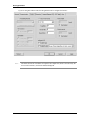
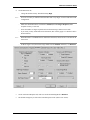
30.6 Embedded Web Server .................................................................................. 159
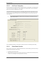
31. Maintenance .................................................................................... 162
31.1 Verification ...................................................................................................... 162
31.2 Replace Memory Backup Battery ................................................................... 163
32. Specifications ................................................................................... 164
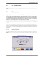
ISC Communications ....................................................... 165
33. ISC Communication ......................................................................... 167
33.1 LAN Connections ............................................................................................ 167
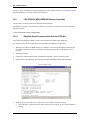
33.2 LNL-ETHLAN (MSS1/MSS100 Ethernet Controller) ....................................... 168
33.3 LNL-ETHLAN-MICR (Micro Serial Server) ..................................................... 171
33.4 CoBox Micro 100 ............................................................................................ 173
33.5 CoBox Token Ring Serial Server (LNL-COBOX-201TR) ................................ 179
33.6 Lantronix CoBox-DR ....................................................................................... 184
33.7 Lantronix SecureBox SDS1100/1101 ............................................................. 185
33.8 Lantronix UDS-10/UDS100/UDS200/UDS1100 ............................................. 190
33.9 Commonly Used Values ................................................................................. 197
33.10 LNL-IC108A/IC109A RS-232 to RS-485 Converter (4-wire) ......................... 198
33.11 LNL-IC108A/IC109A RS-232 to RS-485 Converter (2-Wire) ........................ 199
33.12 Configuring Two LNL-838A RS-232 to RS-485 Converters ......................... 200
33.13 Dial-Up Configuration for the ISC ................................................................. 203
33.14 Securcomm Uniflex DC336 Modems (12 VDC) ............................................ 207
33.15 KBC Fiber Optic Modem ............................................................................... 209
33.16 Comtrol RocketPort Hub Si .......................................................................... 210
6 — revision 1
Hardware Installation Guide
LNL-1100 Input Control Module ....................................... 217
34. Overview of the LNL-1100 ............................................................... 219
34.1 Interfaces ........................................................................................................ 219
34.2 The Input Control Module (Series 2) .............................................................. 220
35. Installation ........................................................................................ 222
35.1 Wiring ............................................................................................................. 222
35.2 Elevator Control .............................................................................................. 226
36. Configuration ................................................................................... 227
36.1 Setting DIP Switches ...................................................................................... 227
36.2 Installing Jumpers ........................................................................................... 230
37. Specifications ................................................................................... 232
LNL-1100-U Input Control Module ................................... 233
38. Overview of the LNL-1100-U Board ................................................. 235
38.1 Package Contents .......................................................................................... 235
39. Installation ........................................................................................ 236
40. Configuration ................................................................................... 237
40.1 Setting DIP Switches ...................................................................................... 237
40.2 Installing Jumpers ........................................................................................... 239
40.3 Status LEDs .................................................................................................... 240
41. Mounting .......................................................................................... 242
42. Wiring ............................................................................................... 244
42.1 Supervised (Software Configurable) Alarm Inputs .......................................... 244
42.2 Unsupervised Alarm Inputs: Power Fail and External (Cabinet) Tamper ....... 245
42.3 Upstream Controller Communication .............................................................. 246
42.4 Control Output Wiring ..................................................................................... 247
42.5 Elevator Control .............................................................................................. 248
42.6 Power and Communications ........................................................................... 249
42.7 UL Listed Installations .................................................................................... 250
43. Specifications ................................................................................... 251
LNL-1200 Output Control Module .................................... 253
44. Overview of the LNL-1200 ............................................................... 255
revision 1 — 7
Table of Contents
44.1 Interfaces ........................................................................................................ 255
44.2 The Output Control Module (Series 2) ............................................................ 256
45. Installation ........................................................................................ 258
45.1 Wiring ............................................................................................................. 258
45.2 Elevator Control .............................................................................................. 260
46. Configuration ................................................................................... 262
46.1 Setting DIP Switches ...................................................................................... 262
46.2 Installing Jumpers ........................................................................................... 265
47. Specifications ................................................................................... 267
LNL-1200-U Output Control Module ................................ 269
48. Overview of the LNL-1200-U Board ................................................. 271
48.1 Package Contents .......................................................................................... 271
49. Installation ........................................................................................ 272
50. Configuration ................................................................................... 273
50.1 Setting DIP Switches ...................................................................................... 273
50.2 Installing Jumpers ........................................................................................... 275
50.3 Status LEDs .................................................................................................... 276
51. Mounting .......................................................................................... 279
52. Wiring ............................................................................................... 281
52.1 Unsupervised Alarm Inputs: Power Fail and External (Cabinet) Tamper ....... 281
52.2 Upstream Communication .............................................................................. 282
52.3 Relay Outputs ................................................................................................. 282
52.4 Elevator Control .............................................................................................. 284
52.5 Power and Communications ........................................................................... 285
52.6 UL Listed Installations .................................................................................... 286
53. Specifications ................................................................................... 287
LNL-1300 Single Reader Interface Module ...................... 289
54. Overview of the LNL-1300 ............................................................... 291
54.1 Interfaces ........................................................................................................ 291
54.2 The Single Reader Interface Module Board (Series 2) ................................... 292
55. Installation ........................................................................................ 294
55.1 Wiring ............................................................................................................. 294
55.2 Elevator Control .............................................................................................. 299
8 — revision 1
Hardware Installation Guide
56. Configuration ................................................................................... 301
56.1 Installing Jumpers ........................................................................................... 301
57. Specifications ................................................................................... 305
LNL-1300-U Single Door Controller Module .................... 307
58. Overview of the LNL-1300-U Board ................................................. 309
58.1 Package Contents .......................................................................................... 309
59. Installation ........................................................................................ 310
60. Configuration ................................................................................... 311
60.1 Setting DIP Switches ...................................................................................... 311
60.2 Installing Jumpers ........................................................................................... 313
60.3 Status LEDs .................................................................................................... 314
61. Mounting .......................................................................................... 317
62. Wiring ............................................................................................... 319
62.1 Supervised (Software Configurable) Alarm Inputs .......................................... 319
62.2 Upstream Communication .............................................................................. 320
62.3 Relay Outputs ................................................................................................. 321
62.4 Downstream Reader Communication ............................................................. 322
62.5 Open Supervised Device Protocol .................................................................. 323
62.6 Elevator Control .............................................................................................. 324
62.7 External (Cabinet) Tamper ............................................................................. 325
62.8 Power and Communications ........................................................................... 325
62.9 UL Listed Installations .................................................................................... 326
63. Specifications ................................................................................... 327
LNL-1320 Dual Reader Interface Module ........................ 329
64. Overview of the LNL-1320 ............................................................... 331
64.1 Interfaces ........................................................................................................ 331
64.2 The Dual Reader Interface Module (Series 2) ................................................ 332
65. Installation ........................................................................................ 335
65.1 Wiring ............................................................................................................. 335
65.2 Elevator Control .............................................................................................. 342
66. Configuration ................................................................................... 344
66.1 Setting DIP Switches ...................................................................................... 344
66.2 Installing Jumpers ........................................................................................... 347
revision 1 — 9
Table of Contents
67. Specifications ................................................................................... 348
LNL-1320-U Dual Door Controller Module ....................... 349
68. Overview of the LNL-1320-U Board ................................................. 351
68.1 Package Contents .......................................................................................... 351
69. Installation ........................................................................................ 352
70. Configuration ................................................................................... 353
70.1 Setting DIP Switches ...................................................................................... 353
70.2 Installing Jumpers ........................................................................................... 356
70.3 Status LEDs .................................................................................................... 357
71. Mounting .......................................................................................... 361
72. Wiring ............................................................................................... 363
72.1 Supervised (Software Configurable) Alarm Inputs .......................................... 363
72.2 Upstream Communication .............................................................................. 364
72.3 Control Output Wiring ..................................................................................... 365
72.4 Downstream Reader Communication ............................................................. 366
72.5 Open Supervised Device Protocol .................................................................. 367
72.6 Unsupervised Alarm Inputs: Power Fail and External (Cabinet) Tamper ....... 368
72.7 Power and Communications ........................................................................... 368
72.8 UL Listed Installations .................................................................................... 369
73. Specifications ................................................................................... 370
LNL-8000 Star Multiplexer ............................................... 373
74. Overview of the LNL-8000 Board .................................................... 375
74.1 Interfaces ........................................................................................................ 375
74.2 The Star Multiplexer Board ............................................................................. 376
75. Installation ........................................................................................ 377
75.1 Wiring ............................................................................................................. 377
75.2 Wiring and Termination .................................................................................. 379
76. Configuration ................................................................................... 381
76.1 Setting DIP Switches ...................................................................................... 381
76.2 Installing Jumpers ........................................................................................... 382
77. Specifications ................................................................................... 383
10 — revision 1
Hardware Installation Guide
LNL-2005W Magnetic Card Access Reader .................... 385
78. Overview .......................................................................................... 387
79. Installation ........................................................................................ 388
79.1 Wiring ............................................................................................................. 388
79.2 Mounting the Reader ...................................................................................... 388
79.3 Weatherproofing the Reader .......................................................................... 388
80. Configuration ................................................................................... 390
80.1 DIP Switch/Jumper Setting ............................................................................. 390
80.2 TTL Interface .................................................................................................. 390
80.3 Grounding the Reader .................................................................................... 391
80.4 Reader Verification ......................................................................................... 391
80.5 Status LEDs .................................................................................................... 391
80.6 Maintenance ................................................................................................... 391
80.7 Product Identification ...................................................................................... 392
81. Specifications ................................................................................... 393
81.1 Reader Mounting Dimensions ........................................................................ 394
81.2 Reader Weather Shield .................................................................................. 396
LNL-2010W/2020W/2020W-NDK/NDKV2 Magnetic Card
Access Reader ................................................................. 397
82. Overview .......................................................................................... 399
83. Installation ........................................................................................ 400
83.1 Wiring ............................................................................................................. 400
83.2 Mounting the Reader ...................................................................................... 400
83.3 Connecting the Keypad (LNL-2020W/NDK/V2 only) ...................................... 400
83.4 Weatherproofing the Reader .......................................................................... 401
84. Configuration ................................................................................... 403
84.1 Standard Format Code Summary ................................................................... 403
84.2 DIP Switch/Jumper Setting ............................................................................. 404
84.3 Keypad Data and Tamper Monitor Signaling .................................................. 405
84.4 TTL Interface .................................................................................................. 405
84.5 Grounding the Reader .................................................................................... 406
84.6 Reader Verification ......................................................................................... 406
84.7 Status Indicators ............................................................................................. 406
84.8 Maintenance ................................................................................................... 407
84.9 Product Identification ...................................................................................... 407
85. Specifications ................................................................................... 408
revision 1 — 11
Table of Contents
85.1 Reader Mounting Dimensions ........................................................................ 409
85.2 Reader Weather Shield .................................................................................. 411
LenelProx Readers .......................................................... 413
86. LenelProx Readers .......................................................................... 415
86.1 Read Range ................................................................................................... 415
86.2 Installation Guidelines .................................................................................... 415
86.3 LenelProx LPMM-6800 ................................................................................... 417
86.4 LenelProx LPSP-6820 .................................................................................... 419
86.5 LenelProx LPKP-6840 and BT-LPKP-NDK .................................................... 422
86.6 LenelProx LPSR-2400 .................................................................................... 426
86.7 LenelProx LPRKP-4600 ................................................................................. 429
86.8 LenelProx LPMR-1824 and LPMR-1824 MC .................................................. 433
86.9 LenelProx LPLR-911 ...................................................................................... 439
Lenel Keypads ................................................................. 447
87. Lenel Keypads ................................................................................. 449
87.1 LNL826S121NN 8-bit Output Keypad Reader ................................................ 449
87.2 Reader Specifications ..................................................................................... 451
Lenel OpenCard Readers ................................................ 453
88. Lenel OpenCard Readers ................................................................ 455
88.1 OpenCard ISO-X Readers .............................................................................. 455
88.2 OpenCard XF1550/XF1560 ............................................................................ 457
88.3 Specifications ................................................................................................. 459
LNL-500B Biometric Reader Interface ............................. 461
89. Overview of the LNL-500B ............................................................... 463
89.1 Interfaces ........................................................................................................ 463
89.2 The Biometric Reader Interface Board ........................................................... 464
90. Installation ........................................................................................ 465
90.1 Wiring ............................................................................................................. 465
12 — revision 1
Hardware Installation Guide
91. Configuration ................................................................................... 470
91.1 Setting DIP Switches ...................................................................................... 470
91.2 Installing Jumpers ........................................................................................... 472
92. Maintenance .................................................................................... 473
92.1 Verification ...................................................................................................... 473
92.2 Memory Backup Battery ................................................................................. 473
92.3 Firmware ......................................................................................................... 473
93. Supported Biometric Readers .......................................................... 474
94. Specifications ................................................................................... 475
HandKey Readers ............................................................ 477
95. Schlage HandKey Readers ............................................................. 479
95.1 HandKey CR, II, and ID3D-R .......................................................................... 479
95.2 MIFARE/iCLASS HandKey Reader ................................................................ 492
Biocentric Solutions .......................................................... 499
96. Overview .......................................................................................... 501
96.1 Interfaces ........................................................................................................ 501
97. Enrollment Readers ......................................................................... 502
97.1 Wiring Enrollment Readers ............................................................................. 502
97.2 Configuring Enrollment Readers .................................................................... 504
97.3 Encoding Smart Cards ................................................................................... 504
98. Verification Readers ........................................................................ 505
98.1 Wiring CombiSmart Readers .......................................................................... 505
98.2 Wiring GuardDog Readers for Verification ..................................................... 509
99. Maintenance .................................................................................... 511
99.1 Tips and Tricks ............................................................................................... 511
Bioscrypt Readers ............................................................ 517
100. Overview ........................................................................................ 519
100.1 V-Pass FX and V-StationA ........................................................................... 519
100.2 V-Smart and V-StationG/H ........................................................................... 521
revision 1 — 13
Table of Contents
101. Installation ...................................................................................... 523
101.1 Reader Power Requirements ....................................................................... 523
101.2 Enrollment Readers ...................................................................................... 523
101.3 V-Pass FX .................................................................................................... 525
101.4 V-StationA .................................................................................................... 529
101.5 V-Smart ........................................................................................................ 534
101.6 V-StationA-G and V-StationA-H ................................................................... 547
101.7 PIV-Station ................................................................................................... 554
101.8 V-Station and V-Flex 4G Readers ................................................................ 556
Schlage Wireless Readers ............................................... 563
102. Overview of Wireless Reader Interfaces ....................................... 565
102.1 Interfaces ...................................................................................................... 565
103. Installation of the Gateway ............................................................ 566
103.1 Wiring ........................................................................................................... 566
104. Configuration ................................................................................. 570
104.1 Setting DIP Switches .................................................................................... 570
104.2 Installing Jumpers ......................................................................................... 572
104.3 Firmware ....................................................................................................... 572
105. Schlage Wireless Configuration ..................................................... 573
105.1 PIM-485-16-OTD .......................................................................................... 573
105.2 Configuration and Demonstration Tool ......................................................... 573
105.3 PIM-OTD ...................................................................................................... 574
106. Readers ......................................................................................... 577
106.1 Use with the LNL-2020W .............................................................................. 577
106.2 OnGuard Configuration ................................................................................ 577
107. Specifications ................................................................................. 579
Schlage Wireless Locks ................................................... 581
108. Overview of Wireless Lock Interfaces ............................................ 583
108.1 Interfaces ...................................................................................................... 583
109. Installation of the LNL-500W ......................................................... 584
109.1 Wiring ........................................................................................................... 584
110. Configuration ................................................................................. 588
110.1 Setting DIP Switches .................................................................................... 588
14 — revision 1
Hardware Installation Guide
110.2 Installing Jumpers ......................................................................................... 590
110.3 Firmware ....................................................................................................... 590
111. Schlage Wireless Configuration ..................................................... 591
111.1 PIM400-485 .................................................................................................. 591
111.2 Configure the PIM400-485 and AD-400 Wireless Lock Range Addresses .. 591
111.3 AD-400 Wireless Locks ................................................................................ 593
111.4 Handheld Device (HHD) ............................................................................... 594
111.5 Synchronization Software ............................................................................. 594
111.6 Install the Schlage Utility Software (SUS) ..................................................... 595
111.7 Link the Wireless Lock to the PIM ................................................................ 596
111.8 Connect the HHD to the Lock ....................................................................... 598
111.9 Use the HHD to Couple to the Lock ............................................................. 598
112. Wiring and Setup ........................................................................... 600
113. Locks ............................................................................................. 603
113.1 OnGuard Configuration ................................................................................ 603
114. Specifications ................................................................................. 605
Command Keypad ........................................................... 607
115. Command Keypad Overview ......................................................... 609
115.1 Communication ............................................................................................. 609
115.2 Specifications ............................................................................................... 621
Index ................................................................................................................ 623
revision 1 — 15
Table of Contents
16 — revision 1
HARDWARE
INSTALLATION
GUIDELINES
Hardware Installation Guide
1
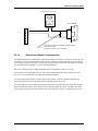
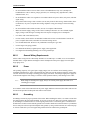
Inputs, Outputs and Interface Signals
Hardware products operate from various power sources and communicate via a variety of I/O interfaces.
Understanding the power requirements and interface signals, their characteristics, merits and limitations will
insure successful installation and a reliable system.
1.1
Power Inputs
1.1.1
AC Power
Some OnGuard hardware products can use an AC power source.
The AC power wiring to power supplies consists of the AC LINE (L), AC NEUTRAL (N), and SAFETY
GROUND (G). These lines from the AC power source to the power input terminals must not be
interchanged.
Interchange of the AC LINE and AC NEUTRAL exposes components within the power supply to the hot
side of the input power even if the AC line switch is turned off. This presents a safety hazard.
Interchange of the AC LINE and SAFETY GROUND places the supply chassis to an AC potential equal to
the input voltage. This could result in a lethal shock hazard or equipment damage.
The interchange of the AC NEUTRAL and SAFETY GROUND may result in ground current flowing
through the power supply chassis and other ground paths, causing unreliable/improper system operation.
The AC LINE input to Hardware power supplies is appropriately fused and switched. Local safety
regulations may require an additional switch/fuse to be installed in the NEUTRAL input.
Do not apply greater than 12 VAC 15% to any hardware product.
1.1.2
DC Power
All OnGuard hardware products can use a DC power source.
When using a DC power supply for a hardware product, the DC power must be isolated electrically from the
AC input side and non-switching, regulated DC power. Readers require +5 or +12 VDC, and all other panels
require either 12 VDC or 12 VAC (except the LNL-1300 and LNL-8000 which require only 12 VDC).
DC power must be supplied through a diode for reverse polarity protection, and must be filtered and
regulated for the electronics. Products intended to be powered from DC should never be powered with an
AC transformer with rectifiers.
The Multiplexer requires a regulated, low ripple (under 20 mV P/P). The power input is fused and protected
from polarity reversal, and a crowbar over-voltage circuit protects against application of wrong voltages.
Do not apply greater than 12 VDC 15% to any hardware product.
To insure reliable operation of all components of the system, it is important that all power supplies used to
power the devices are completely isolated from the AC power source.
revision 1 — 19
Hardware Installation Guidelines
1.2
Alarm Inputs
1.2.1
Unsupervised Alarms
Unsupervised alarm inputs sense simple contact closure. Open circuit results in an alarm condition. These
inputs are protected by pull-ups, series limiting resistors, and clamp diodes against transients, like
ElectroStatic Discharge. The signal is then buffered to reduce the effect of noise.
Open contacts should result in terminal voltages of 3.5 to 5 VDC. Closed contact terminal voltage should be
between 0 and 0.8 VDC.
1.2.2
Supervised Alarms
Various OnGuard hardware products provide contact supervision. These inputs require an end-of-line (EOL,
1K10%) terminator to be installed with the contact to be monitored. This can be configured within the
software. Input protection is similar to that of the unsupervised input, however the input is also filtered to
reject 50/60 Hz AC coupling.
The supervised input can sense contact conditions of SAFE, ALARM, and FAULT. It also accommodates
normally closed (NC) and normally open (NO) contacts, which is configurable within the application.
1.3
Reader Inputs/Outputs
1.3.1
Reader Data Input
Reader data input is similar to unsupervised alarm input. Reader data input interfaces to reader DATA 1/
DATA 0 (WD1/WD0) open collector signals and produces a nominal signal swing of 0 to 5 volts.
1.3.2
Open Collector Output
Open collector output is used by readers to send reader data DATA1/DATA0 (WD1/WD0) and to control
external LEDs. Pull-up resistors and diode clamps are provided for reader data outputs. This type of
interface is limited to 500 feet (152.4 m).
1.4
Relay Outputs
Some Lenel hardware products provide form C relay contact outputs. These are dry contacts that are capable
of switching signals as well as higher current loads. However, once they are used to switch current (for
example, a door strike), they can not be used reliably to switch small signals (for example, dialer input.)
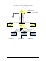
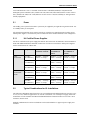
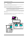
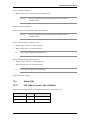
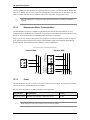
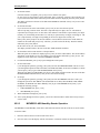
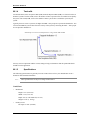
1.5
RS-485 Communication Overview
The EIA RS-485 standard defines an electrical interface for multi-point communication on bus transmission
lines. It allows high-speed data transfer over extended distance (4000 feet/1219 m.) The RS-485 interface
20 — revision 1
Hardware Installation Guide
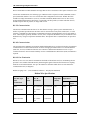
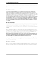
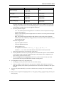
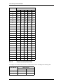
uses a balanced differential transmitter/receiver to reject common mode noise. The following table is a
comparison of interfaces commonly used in access/alarm systems.
RS-485
RS-232C
Modem
20mA Loop
Mode of
Operation:
Differential DC
coupled
Single-ended DC
coupled
Differential AC
coupled
Single-ended
current
DC
Isolation:
No
No
Yes
Usually Isolated
Distance:
4000 feet
50 feet
Phone Line
1000 feet
No. of
Devices on
1 Line:
32
2
2
Limited by Loop
Voltages
Data Rate:
10M bps
20K bps
19.2K bps
2400 bps
Unlike the RS-232C or current loop interfaces, the RS-485 interface allows multiple devices to
communicate at high data rates on a single cable, over long distance. Obviously, the RS-485 interface
provides advantages in cost savings for installation and improved system performance, but it also brings
about problems which would not commonly be seen on systems using RS-232C or current loop interfaces.
Using long communication cable with multiple devices often necessitates powering devices from different
power sources. This can result in ground faults and ground loops, which can cause communication problems
and possible equipment damage. Because the RS-485 interface communicates in the base band and provides
no DC isolation, ground fault places devices at different electrical ground levels and causes large ground
currents to flow. Possibilities of ground fault call for careful system planning and installation verification.
Communication cables exceeding 4000 feet can also create noise and signal reflection problems if proper
cable is not used or if the cable is not correctly terminated.
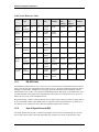
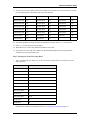
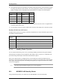
Belden Wire Specifications
Trade Number
UL NEC Type
CSA
Certification
Number
of Pairs
Nominal
D.C. R.
Conductor
Shield
9841
1
24.0 ohms/M
3.35 ohms/M
78.7 ohms/
km
11.0 ohms/K
24.0 ohms/M
2.2 ohms/M
78.7 ohms/
km
7.2 ohms/K
24.0 ohms/M
15.5 ohms/M
78.7 ohms/
km
50.9 ohms/km
NEC CM CSA
9842
2
NEC CM CSA
88102
NEC CMP CSA
2
Nominal
Impedance
(Ohms)
Nominal Capacitance
pF/feet
pF/meter
120
12.8
42
120
12.8
42
100
12.95
42
revision 1 — 21
Hardware Installation Guidelines
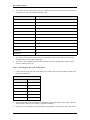
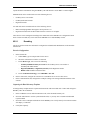
Cable Cross Reference Table
Purpose
Cable
type
Gauge
Cond.
Description
Belden
number
South
West
number
WCW
part
number
WP
number
RS-485,
2-wire
Nonplenum
24
2P
overall
shield
9842
170105
C4842
D4852
RS-485,
2-wire
Plenum
24
2P
overall
shield
82842,
89842
n/a
n/a
n/a
RS-485,
4-wire
Nonplenum
24
3P
overall
shield
9843
n/a
n/a
n/a
RS-485,
4-wire
Plenum
24
3P
overall
shield
88103
110060
42003
n/a
RS-232
Nonplenum
24
5
overall
shield
9610
170155
C0953
n/a
Plenum
24
6
overall
shield
83506
110070P
C3165
n/a
Nonplenum
22/24
6
overall
shield
5504FE,
9536
161240
C0743
3270
Plenum
22/24
6
overall
shield
6504FE
110253P
444351-04
253270B
Nonplenum
18
2
overall
shield
5300FE,
8760
163004
414109
293
Plenum
18
2
overall
shield
6300FE,
88760
112000P
442320
25293B
Reader
drops
12 VDC
power
1.5.1
RS-485 Cable
Field hardware products that are series 1 use 4-wire or 2-wire RS-485 full communication between devices.
Only 2-wire RS-485 cable configuration can be used for series 2. The main run RS-485 cable used must be
shielded, low capacitance, stranded, two twisted pairs with 100-ohm characteristic impedance or better
(Belden 9842 4-wire or 9841, 2-wire, plenum cabling Belden 88102, West Penn, or equivalent). Wire size is
24 AWG minimum. Total length of the communication cable must not exceed 4000 feet (1219 m) for 24
AWG wire size per leg of the communication tree.
Drops (down leads or stubs) to readers and other devices must be kept as short as possible (no longer than 10
feet). Use shielded 24 AWG cable (Belden 9502, or equivalent), when terminating to the 3-position for 2wire RS-485 or the 5-position for 4-wire RS-485, insulation displacement connector.
1.5.2
Use of Signal Ground (SG)
The signal ground (SG) provides a common mode signal reference for the communicating devices. Each
device must connect its SG to the cable shield drain wire. Failure to use the SG connection may cause
22 — revision 1
Hardware Installation Guide
communication errors. If the environment is known to be noisy, an additional wire may be used for the
signal ground. The shield can then be grounded at one end only (to prevent ground loops) as a signal ground.
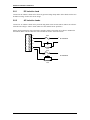
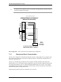
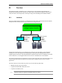
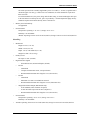
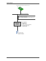
1.5.3
Device to Device Connection
Communication cables for RS-485 should be laid out in a daisy chain. Long stubs (T connection) should be
avoided because they create discontinuities and degrade signals. DO NOT connect devices in STAR
configuration unless using the LNL-8000 Star Multiplexer. STAR connection creates long stubs and causes
difficulty in cable termination.
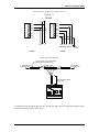
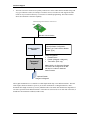
1.5.4
Cable Termination
RS-485 communications is designed for higher data transmission speeds and also simplifies installation by
allowing each device to be multi-dropped from a single communication line or bus. With the increase data
speeds and transmitting and receiving the data over a single communications line, there is higher risk of
external noise. External noise could be in the form of line impedance, line ringing, or RF interference. When
using the specified communications cabling the risk of noise is all but eliminated. To ensure that the data is
sent and received without error, some End-of-Line termination of the RS-485 bus may be required.
•
RS-485 Cable termination from Host to Controller The device used to convert RS-232
communication to RS-485 determines the termination necessary for this segment of the RS-485
communication bus. These communications devices, pre-bias the RS-485 signal, which marks the state
of the signal being sent and allows the line to flow for reliable communications. This is true for most
devices that are used for Host to ISC communications, but any device that has been approved by Lenel
will indicate how termination should be configured for proper operation in its documentation. Refer to
the specific device diagrams being used in the following sections of this hardware manual.
•
RS-485 Cable termination from controller to down stream modules (LNL-500X, 1100, 1200, 1300,
1320, 4000, 8000) Termination of this section of the RS-485 bus always remains the same. Each end of
the RS-485 bus must be terminated using the on-board jumpers provided with each piece of OnGuard
hardware. Please refer to the termination drawings for each component being installed in this hardware
manual.
•
RS-485 Cable termination from LNL-500X to Third-party hardware devices Termination may be
different for each RS-485 hardware device that is connected to the LNL-500X interface gateway
module. Please refer to the gateway model being used for the hardware installation application.
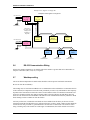
1.6
RS-232 Interfaces
A number of products provide RS-232C interface for communication. This interface is intended for short
distance communication because its high impedance is more susceptible to noise. Cable length is generally
limited to 50 feet (15m.) If required, this distance may be extended to a few hundred feet by using low
capacitance shielded cables.
revision 1 — 23
Hardware Installation Guidelines
2
System Wiring and Other Considerations
Proper installation is essential to the safe and reliable operation of the OnGuard system. Improper or
incorrect wiring will lead to unreliable operation or damage to system components. When system
components are powered by different power sources, great care must be exercised in planning and wiring the
system. The following paragraphs provide some guidelines for successful system interconnection.
2.1
General Wiring Considerations
There are different system wiring considerations for different groups of wiring, depending on the signal
levels the wires are to carry. System wires can be generally separated into the following groups:
•
Power distribution wires
•
Data communication wires
•
Sensor wires.
To avoid cross-talk, follow the wire requirements for each type of communication, or use different conduit
for different signal groups.
2.1.1
Device Placement
Observe the distance limitation of each type of signal when planning device placement. Modems and line
extenders can be used for extended distance.
Do not run any wires near utility AC power wiring, lightning rod grounding wire, etc. to avoid externally
generated transients. Grounding is required for ESD protection and safety.
2.1.2
Power Requirements
When planning a system, know the power requirement of each device. If multiple devices are to share a
common power supply, care must be exercised to avoid excessive voltage loss on the wires. Voltage loss can
lead to communication problems when devices are talking/listening on different grounds.
Voltage loss is directly proportional to wire resistance and the current the wire carries. Place the power
supply as close to the equipment as possible. Select appropriate wire size for the load.
2.1.3
Current Overload
When designing any system, you must know the power requirement of each component being used within
that system (refer to power chart below) as well as the actual output of the power supplies being used. If
multiple devices are to share a common power supply, care must be taken to avoid excessive voltage loss
through the power transmitting wires. Voltage loss can lead to intermittent communications problems when
devices are consuming more power than the power supply is able to give. Other causes of voltage loss are
directly proportional to wire resistance and current that the wire carries. When designing a system, place the
power supply as close to the equipment as possible. The farther away the equipment is from the power
supply, the larger the gauge of wire needed to ensure adequate current is being supplied at the device. Be
sure to select the appropriate wire size for the distance between the power source and the equipment.
24 — revision 1
Hardware Installation Guide
When choosing a power supply be sure never max out the current load of the supply. Always use a 25%
overage factor when sizing your supply as a safety operation. Always use an isolated, non-switching,
regulated power supply.
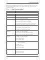
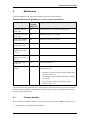
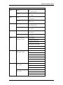
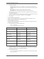
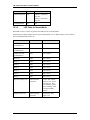
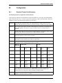
2.1.4
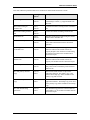
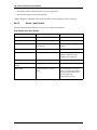
Power Requirements Table
Device
Power Required
ACCESS HARDWARE
LNL-500
12 VAC (10.2-13.8 V), 400 mA RMS or 12 VDC (10.8-13.2 V), 250 mA
LNL-1000
12 VAC (10.2-13.8 V), 600 mA RMS or 12 VDC (10.8-13.2 V), 350 mA
LNL-2000
12 VAC (10.2-13.8 V), 650 mA RMS (800 mA RMS with NIC) or 12 VDC
(10.8-13.2 V), 400 mA (550 mA with NIC)
LNL-2210
12 VDC ± 10%, 200 mA minimum, 900mA maximum
PoE power input 12.95W, compliant to IEEE 802.3af
For UL installations, PoE powered devices shall not be used; power for
these devices must be provided by a UL294 Listed source (12 VDC).
LNL-2220
12 to 24 VDC ± 10%, 500 mA maximum (plus reader current)
12 VDC @ 250 mA (plus reader current) nominal
24 VDC @ 150 mA (plus reader current) nominal
LNL-3300
12 to 24 VDC ± 10%, 300 mA maximum
12 VDC @ 240 mA (325mA with CoBox-Micro) nominal
24 VDC @ 135 mA (175mA with CoBox-Micro) nominal
LNL-1100
12 to 24 VDC ± 10%, 350 mA maximum
12 VDC @ 300 mA nominal
24 VDC @ 220 mA nominal
LNL-1100-U
Note:
For UL installations, refer to section UL Listed Installations on
page 250 for this device.
12 to 24 VDC ± 10%
12 VDC @ 300 mA nominal
24 VDC @ 150 mA nominal
LNL-1200
12 to 24 VDC ± 10%, 1100 mA maximum
12 VDC @ 850 mA nominal
24 VDC @ 450 mA nominal
revision 1 — 25
Hardware Installation Guidelines
Device
Power Required
LNL-1200-U
Note:
For UL installations, refer to section UL Listed Installations on
page 286 for this device.
12 to 24 VDC ± 10%
12 VDC @ 805 mA nominal
24 VDC @ 407 mA nominal
LNL-1300
12 to 24 VDC ± 10%, 150 mA maximum (plus reader current)
12 VDC @ 110 mA (plus reader current) nominal
24 VDC@ 60 mA (plus reader current) nominal
LNL-1300-U
Note:
For UL installations, refer to section UL Listed Installations on
page 326 for this device.
12 to 24 VDC ± 10%
12 VDC @ 700mA (includes reader current) nominal
24 VDC@ 350 mA (includes reader current) nominal
LNL-1320
12 to 24 VDC ± 10%, 550mA maxiumum (plus reader current)
12 VDC @ 450 mA (plus reader current) nominal
24 VDC @ 270 mA (plus reader current) nominal
LNL-1320-U
Note:
For UL installations, refer to section UL Listed Installations on
page 369 for this device.
12 to 24 VDC ± 10%
12 VDC @ 1200 mA (includes reader current) nominal
24 VDC @ 600 mA (includes reader current) nominal
LNL-2005W
12 VDC (10.2 to 13.8VDC), 50 mA
LNL-2010W
12 VDC (10.2 to 13.8VDC), 80 mA
LNL-2020W
12 VDC (10.2 to 13.8VDC), 80 mA
LNL-8000
12 VDC, 250 mA
Indala Proximity
ASR-505
5-14 VDC, 45 mA
ASR-110
10.5-14 VDC, 180 mA
ASR-112
10.5-14 VDC, 180 mA
ASR-603
4 -16 VDC, 350 mA
ASR-605
4 -16 VDC, 350 mA
26 — revision 1
Hardware Installation Guide
Device
Power Required
ASR-610
4 -14 VDC, 500 mA
ASR-620
12 - 24 VDC, 900 mA-1.2 A
ASR-136
24 VDC, 400 mA
ASR-500
5-14 VDC, 45 mA
ARK-501
5-14 VDC, 50 mA
Essex Keypads
KTP-16212SLI
12 VDC, 15 or 85 mA
KTP-163SN
12 VDC, 15 or 85 mA
HID Proximity
5365
5-16 VDC, 160 mA
5355
10-28 VDC, 160 mA
5395
4-16 VDC, 160 mA
5375
24 VDC, 1.7 A
5385
24 VDC, 50 mA
6000
24 VDC, 2.0 A
6030
10-28 VDC, 150 mA
HID Wiegand
SRE-3100500
5-12 VDC, 40 mA
SRE-3100130
5-12 VDC, 40 mA
SRE-3102500
5-12 VDC, 60 mA
HID iCLASS
6100
10-16 VDC, 80-300 mA @ 12 VDC
6110
10-16 VDC, 80-300 mA @ 12 VDC
6120
10-16 VDC, 80-260 mA @ 12 VDC
6130
10-16 VDC, 72-244 mA @ 12 VDC
6111
10-16 VDC, 80-300 mA @ 12 VDC
6121
10-16 VDC, 100-350 mA @ 12 VDC
6131
10-16 VDC, 72-244 mA @ 12 VDC
6125A
5-12 VDC, 70-120 mA @ 12 VDC
Lenel OpenCard
LNL-XF1100D
6-16 VDC, 95-254 mA
revision 1 — 27
Hardware Installation Guidelines
Device
Power Required
LNL-XF2100D
8-16 VDC, 95-218 mA
LNL-XF2110D
8-16 VDC, 120-215 mA
Typical door strike power is estimated at 24 VDC, 300 mA, consult manufacturer specifications for actual
values.
Note:
Device power requirements are subject to change without notice. These tables are intended
only as a guide.
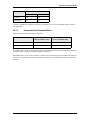
FIELD HARDWARE POWER SUPPLIES AVAILABLE
Part #
Description
LNL-AL400ULX
UL Listed power supply - 12 VDC (4A output) or 24 VDC (3A output),
switch selectable, 120 VAC input, continuous supply current with enclosure,
lock and open frame transformer, UPS capable (battery optional). The
AL400ULX is a power limited supply/chargers that will convert a 28 VAC
input, into a power limited 12 VDC or 24 VDC output. Operating
temperature: 0° to +49° C (32° to 120° F). Humidity: 0 to 85% RHNC. BTU
output: 33 BTU.
LNL-400X-CE220
CE marked power supply - 12 VDC (4A output) or 24 VDC (3A output),
switch selectable, 230 VAC input, continuous supply current with enclosure,
lock and open frame transformer, UPS capable (battery optional). Operating
temperature: 0° to +49° C (32° to 120° F). Humidity: 0 to 85% RHNC. BTU
output: 33 BTU.
LNL-AL600ULX-4CB6
UL Listed power supply - 12 VDC or 24 VDC 6A output (switch selectable),
120 VAC input, continuous supply current with enclosure, lock and open
frame transformer, UPS capable (battery optional). Operating temperature: 0°
to +49° C (32° to 120° F). Humidity: 0 to 85% RHNC. BTU output: 49 BTU.
LNL-600X6-CE220
CE marked power supply - 12 VDC or 24 VDC 6A output (switch
selectable), 230 VAC input, continuous supply current with enclosure, lock
and open frame transformer, UPS capable (battery optional). Operating
temperature: 0° to +49° C (32° to 120° F). Humidity: 0 to 85% RHNC. BTU
output: 49 BTU.
LNL-CTX
Hardware enclosure (12 x 16 x 4.5 inches) with lock and tamper switch
support up to two Lenel access hardware modules (UL approved).
LNL-CTX-6
Hardware enclosure (18 x 24 x 4.5 inches) with lock and tamper switch
support up to six Lenel access hardware modules (UL approved).
ABT-12
Battery Kit, 12 VDC, 12AH Battery (PS-12120).
For a complete listing of our products, consult the Lenel Price Book.
28 — revision 1
Hardware Installation Guide
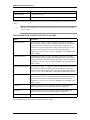
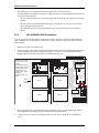
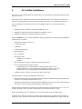
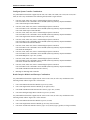
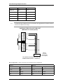
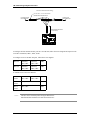
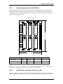
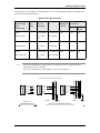
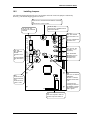
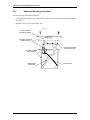
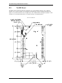
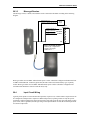
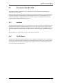
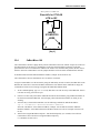
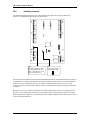
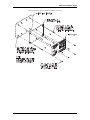
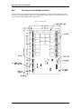
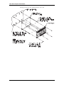
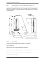
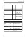
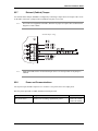
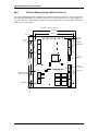
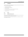
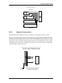
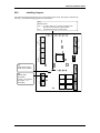
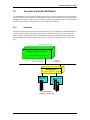
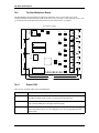
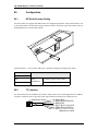
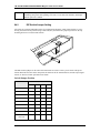
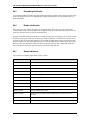
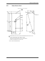
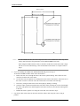
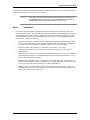
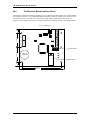
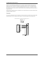
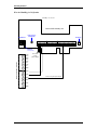
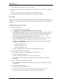
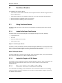
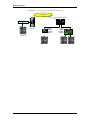
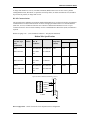
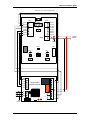
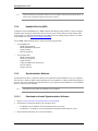
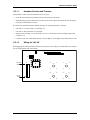
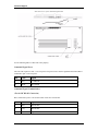
2.2
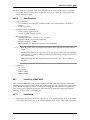
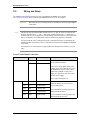
Mounting
Most modules are 6 x 8 inches in size, with mounting holes along the long edge. Up to two (2) units can be
mounted in a single LNL-CTX enclosure. The LNL-CTX-6 allows for up to six (6) modules.
LNL-CTX
12.5"
1"
12.5"
S
Power Switch
Power Supply
2.00"
Piano Hinge
2.00"
3.00"
3.00"
Hardware
Standoffs
Hardware
Standoffs
2.00"
2.00"
Optional
Battery
5.50"
1.75"
1.25" 0.875"
1.75"
15.5"
Transformer
5.50"
D
th
ep
=
5"
4.
revision 1 — 29
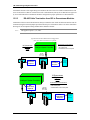
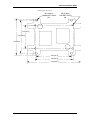
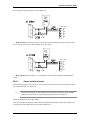
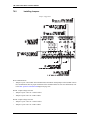
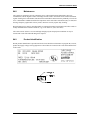
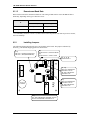
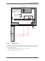
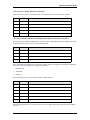
Hardware Installation Guidelines
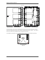
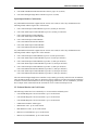
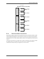
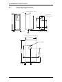
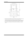
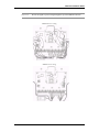
LNL-CTX-6
18.0000
3.5625
8.2500
0.1869
3.7500
0.9375
0.1869
0.3750
0.1869
0.3750
0.3750
1.0000
3.7500
5.5000
2.0000
5.5000
6.5000
6.5000
2.0000
Power Supply
Cabinet Lock
24.0000
1.5000
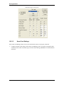
5.5000 24.2500
2.0000
2.0000
5.5000
5.0000
2.0000
Main Fuse
1.1250
5.5000
0.8750
5.5000
5.2500
1.0000
0.1869
0.1869
0.3750
2.0000
3.0000
2.0000
0.1869
0.3750
0.3750
2.5000
2.5000
2.000
18.3750
3.0000
0.8125
1.1875
3.3750
18.0000
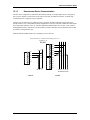
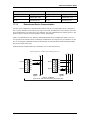
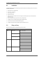
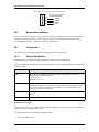
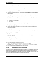
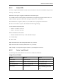
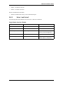
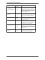
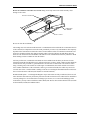
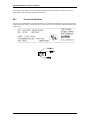
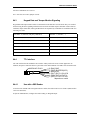
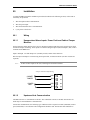
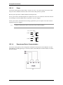
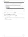
For smaller modules, only four of the mounting holes are used, the last two holes need support standoffs
which come installed from the factory. The exception is the single reader interface module — up to eight (8)
units can be mounted in any standard 2-gang or 3-gang junction enclosure.
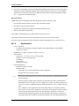
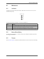
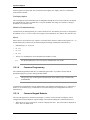
The standoffs for the hardware come in a separate package. The diagram below illustrates positioning.
INSERT
STANDOFFS
HERE
DO NOT DISPOSE
[QTY 2]
30 — revision 1
Hardware Installation Guide
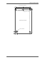
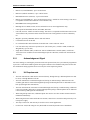
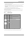
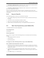
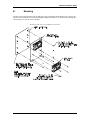
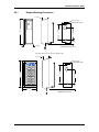
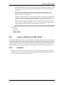
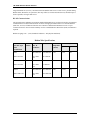
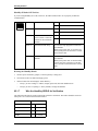
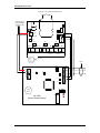
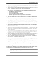
LNL-CTX knockout diagram
0.8125
5.1875"
4.8125"
0.875"
0.375" Clearance Hole
0.1875" Slots nominal
0.125"
3/4" and 1" Knock Outs
Backbox Mounting Hole Configuration
3/4" and 1" Knock Outs
1.0"
1.50"
revision 1 — 31
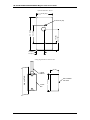
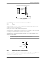
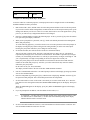
Hardware Installation Guidelines
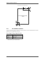
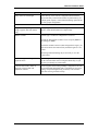
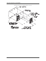
LNL-CTX knockout location drawing
6.0"
1.0"
1/2" and 3/4 knockout location
drawing
1.0"
1.5"
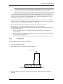
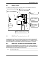
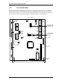
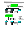
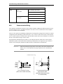
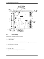
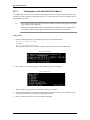
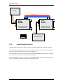
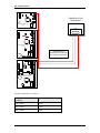
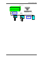
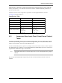
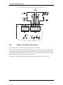
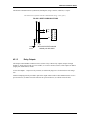
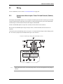
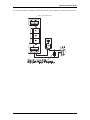
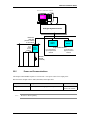
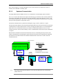
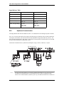
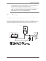
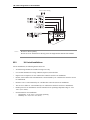
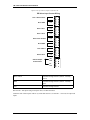
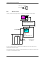
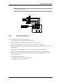
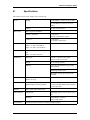
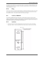
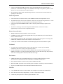
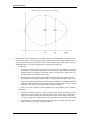
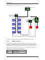
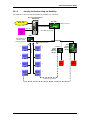
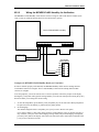
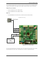
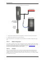
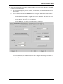
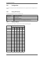
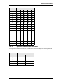
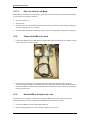
2.2.1
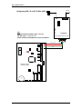
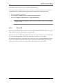
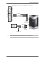
LNL-AL400ULX Installation
The LNL-AL400ULX should be installed in accordance with article 760 of the National Electrical Code and
NFPA70 as well as all applicable local codes.
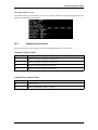
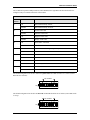
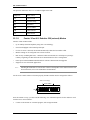
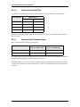
Power Supply Voltage Output Selections
Output
Switch position
12 VDC
SW 1 closed
24 VDC
SW 1 open
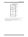
1.
Mount the enclosure in desired location.
32 — revision 1
Hardware Installation Guide
Hardware
Power
Limited
Devices
G
DC Output,
Battery & AC
Supervision
Circuit
(power limited)
black
red
black
red
N
Hardware
black
L
white
Cabinet
Tamper
Switch
Fuse
Cover
+ BAT –
AL400ULXB
Twoposition
Switch
green
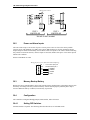
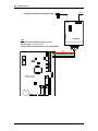
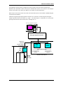
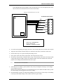
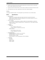
Input 120VAC, 60Hz, 1.45 amp
+ DC –
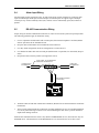
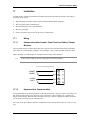
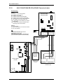
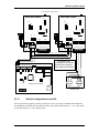
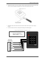
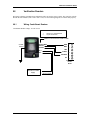
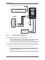
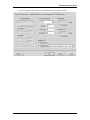
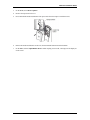
Connect unswitched AC power (120 VAC/60 Hz) to terminals marked L, G, N, dedicated to the Burglar
Alarm/Access Control Subsystem.
Neutral - white
Hot - black
Ground - green
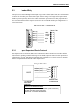
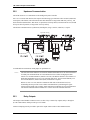
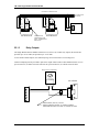
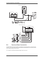
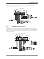
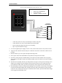
2.
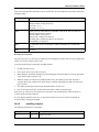
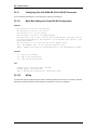
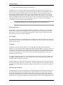
BAT FAIL
NC C NO NC C NC
AC FAIL
CAUTION: Deenergize unit prior
to servicing. For
continued protection against risk of
electric shock and
fire hazard,
replace fuse with
the same type and
rating - 3.5A,
250V. Replace
protective cover
on fuse of the
AL400ULXB
board before
energizing unit.
Do not expose to
rain or moisture.
To Battery
in CTX
3.
Secure the green wire lead to earth ground. Use 18 AWG or larger for all power connections (Battery,
DC output). Keep power limited wiring separate from non-power limited wiring (120 VAC/60 Hz Input,
Battery Wires). A minimum of 0.25 inch spacing must be provided between power wires.
4.
Connect devices to be powered to terminals marked + DC –.
Note:
It is important to measure output voltage before connecting devices. This helps avoid potential
damage.
5.
For UL Access Control applications, batteries are required. When batteries are not used, a loss of AC
will result in the loss of output voltage. When using stand-by batteries, they must be lead acid or gel
type. Connect battery to terminals marked + BAT – (battery leads included). Use two 12 VDC batteries
connected in series for 24 VDC operation.
6.
Connect appropriate trouble reporting devices to AC Fail and Low Battery supervisory relay outputs
marked NC, C, NO. Use 22 AWG to 18 AWG for AC Fail and Low Battery reporting. AC Failure will
report in five minutes. For a six-hour delay on reporting, cut resistor R1.
revision 1 — 33
Hardware Installation Guidelines
7.
Wire routing note: UL two panel installation instructions for LNL-CTX enclosures
To install multiple Lenel hardware panels into a single enclosure, the following guidelines must be used
for certified UL installations.
•
All wire connections that cross over the hinge side of the door must be wire wrapped or tie wrapped
together.
•
All wire must be routed behind the hardware panel so that the wires are secure from movement
when opening and closing the door.
•
All connections for the lock side of the enclosure must come from behind the Lenel hardware
devices.
2.2.2
LNL-AL600ULX-4CB6 Installation
The LNL-AL600ULX-4CB6 should be installed in accordance with article 760 of the National Electrical
Code of NFPA72 as we as all applicable local codes. If you are located in Canada, refer to the Canadian
Electrical Code.
1.
Mount the enclosure in desired location.
2.
The power supply is pre-wired to the ground (chassis). Connect main incoming ground to the provided
green grounding conductor lead. Connect unswitched AC circuit (115 VAC/60 Hz) dedicated to the
Burglar Alarm/Access Control Subsystem to terminals marked L, G, N.
Input 115 VAC, 60 Hz, 1.9 amp
Neutral - white
Hot - black
Ground - green
Twoposition
Switch
Hardware
white
Fuse
Cover
green
black
+ DC –
black
red
black
red
To Battery
in CTX
Main Fuse
ON - OFF
PD4A
– +
AC FAIL
+ BAT –
Input
F1
F2
F3
F4
Hardware
Hardware
1P, 2P, 3P & 4P = Fused Outputs
1N, 2N, 3N & 4N = Common Outputs
Output Circuit 1
Output Circuit 2
Output Circuit 3
Output Circuit 4
3.
Keep power limited wiring separate from non-power limited wiring (115 VAC/60 Hz Input, Battery
wires). Minimum 0.25 inch spacing must be provided between power wires.
4.
Connect devices to be powered to terminals marked (1P-1N, 2P-2N, 3P-3N, 4P-4N) and distribute
evenly.
34 — revision 1
1 1 2 2 3 3 4 4
PN PN PN PN
NC C NO NC C NO
Battery & AC
Supervision
Circuit
(power limited)
AL600ULX
BAT FAIL
Hardware
CAUTION:
De-energize unit
prior to servicing.
For continued
protection
against risk of
electric shock
and fire hazard,
replace fuse with
the same type
and rating - 3.5A,
250V. Replace
protective cover
on fuse of the
AL600ULXB
board before
energizing unit.
Do not expose to
rain or moisture.
L G N
Hardware
Cabinet Tamper Switch
Power
Limited
Devices
Hardware
Enclosure dimensions:
24 H x 18 W x 4.5 D
inches
Unit includes cabinet,
cabinet tamper switch,
power supply, power
distribution circuit,
battery leads, access
hardware
mounts/screws, and
locks.
Hardware Installation Guide
Note:
It is important to measure output voltage before connecting devices. This helps avoid potential
damage. Use 18 AWG or larger wire for all power connections (battery, DC outputs).
For UL Access Control applications, batteries are required. When batteries are not used, a loss of AC
will result in the loss of output voltage. When the use of stand-by batteries is desired, they must be lead
acid or gel type. Connect battery to terminals marked + BAT – (battery leads included). Use two 12
VDC batteries connected in series for 24 VDC operation.
5.
Connect appropriate trouble reporting device to the Battery Fail and AC Fail supervisory relay outputs
marked NC, C, NO. Use 22 AWG or 18 AWG for AC Fail/Battery Fail reporting. AC Failure will report
within 5 minutes. For a six-hour delay on reporting, cut resistor RL1.
6.
Connect cabinet tamper switch to cabinet tamper circuit on the Lenel access hardware.
7.
Wire routing note: UL six panel installation instructions for LNL-CTX enclosures
To install multiple Lenel hardware panels into a single enclosure, the following guidelines must be used
for certified UL installations.
•
All wire connections that cross over the hinged side of the door must be wire wrapped or tie
wrapped together.
•
All wire must be routed behind the hardware panels so that the wires are secured from movement
when opening and closing the door.
•
All connections from the lock side of the enclosure must come from the Lenel hardware devices.
2.2.3
AC Indicator
UL294 installations require an external AC indicator.
1.
Locate the “AC FAIL” terminals.
2.
Wire an LED indicator according to the following diagram.
AC indicator wiring
LED
BAT FAIL
3.
NO
NC
C
C
NC
NO
AC FAIL
Install the indicator on the outside of the enclosure. It should be installed using the designated AC
knockout.
revision 1 — 35
Hardware Installation Guidelines
2.2.4
Cabinet Tamper
Cabinet tamper for all enclosures must be connected and programmed for UL installations.
2.3
Ground Wiring
Each hardware product must be grounded to provide ESD protection, personnel safety, and signal reference
for devices which communicate with each other. Grounding provides a good shield against external
transients. See the installation manuals for the grounding point of each product.
There are three types of circuit grounds in systems using hardware products:
•
DC negative
•
RS-485 signal ground
•
Safety ground
2.3.1
DC Negative
The DC ground provides signal reference for devices to communicate. It is the DC return from the power
supply.
2.3.2
RS-485 Signal Ground (SG)
The RS-485 signal ground is connected to the DC ground internal to a device through a current limiting
resistor. It provides a signal reference for the RS-485 interface.
2.3.3
Grounding System
A grounding system can be viewed as two subsystems: the DC system and the ground system. The DC
system consists of all interconnected power supply returns, DC distribution wiring, and load devices. The
principal function of the DC system is to provide signal reference for communication. The ground system
consists of all chassis grounds for power supplies and other devices, safety grounds, and AC grounds.
Ground connection should be made to avoid ground loop problems.
Ideally, there should be ONLY ONE ground return point in a power supply system.
2.3.4
Safety Ground
Safety ground (copper wire of 16 AWG minimum) is part of the AC power system. To avoid ground loop
current, there must be NOT more than one point at which the safety ground connects to the DC ground.
The RS-485 signal ground must be isolated from the safety ground. This means that the RS-485 cable shield
must be insulated so that it will NOT accidentally short circuit to the conduit in instances where the conduit
is connected to the safety ground.
The National Electrical Code and other safety regulations require that all equipment chassis and or
enclosures be grounded in order to prevent shock hazards. Each device must have a green wire safety
ground. The function of the green wire safety ground is to provide a redundant path for fault currents and to
insure that the circuit breaker will open in the event of a fault. In addition, grounding the enclosure provides
a path for ESD dissipation, thus protecting sensitive electronic devices.
36 — revision 1
Hardware Installation Guide
2.4
Alarm Input Wiring
All alarm inputs require twisted pair wires. An end-of-line (EOL) resistor terminator is required for each
supervised alarm input. Both supervised and unsupervised alarm inputs can support single or multiple
contacts per loop. Connect normally closed (NC) contacts in series and normally open (NO) contacts in
parallel.
2.5
RS-485 Communication Wiring
Proper wiring for RS-485 communication interfaces is critical for successful system turn-up and operation.
The following guidelines apply for all RS-485 wiring.
1.
Use low capacitance shielded cable with 2 twisted pairs, characteristic impedance 120 ohms (Belden
9842 or equivalent) for the main RS-485 run.
2.
Keep the main run maximum end-to-end distance below 4000 feet.
3.
Use daisy chain configuration, NOT star configuration, to connect devices.
4.
Use shielded 24 AWG cable with 2 twisted pair (Belden 9502 or equivalent.) for down leads (drops or
stubs).
5.
Keep down leads as short as possible (no longer than 10 feet).
RS-485 CABLE, 100 Ohm IMPEDANCE
BELDEN 9842 OR EQUIVALENT
TO PREVIOUS UNIT
OR TERMINATOR
TO NEXT UNIT
OR TERMINATOR
KEEP DOWN LEAD SHORT
(10 FEET MAX.)
Reader Interface Module
6.
Terminate cables at both ends with RS-485 terminators (hardware has on-board terminators for RS-485
termination).
7.
Always use the signal ground (SG) connection. Carefully insulate the SG wire for a reliable installation.
Use 24 GA plastic sleeving over the SG wire when terminating the cable to the 5-position insulation
displacement mating connector.
Each RS-485 communication line can have any number of DEPENDENT devices, but must have only one
MASTER device. The transmit lines of the MASTER device are connected to the receive lines of the
revision 1 — 37
Hardware Installation Guidelines
DEPENDENT devices and the receive lines of the MASTER device are connected to the transmit lines of
the DEPENDENT devices. Observe the + and the - of each pair (NOTE: only applies to 4-wire RS-485
wiring).
Refer to the following diagrams for RS-485 Signal Ground and Termination.
RS-485 Multi-drop Wiring and EOL Termination
RS-485 Multi-drop Wiring and EOL Termination
ISC
T
T+ T- SG
T
= On Board Termination
PVC Cover Wire/or Drain
Wire
PVC Cover Wire
Earth Ground,
one point only
per ISC
PVC Cover Wire
Shield
T+ T- SG
T+ T- SG
T+ T- SG
Dual Reader
Interface
Biometric Reader
Gateway
Dual Reader
Interface
T
T
T+ T- SG
Downstream ports
2 & 3 typical
T+ T- SG
Biometric Reader
Enclosure Ground
38 — revision 1
T+ T- SG
Biometric Reader
Enclosure Ground
T+ T- SG
Biometric Reader
Enclosure Ground
Hardware Installation Guide
RS-485 Multi-drop Wiring and EOL Termination: ISC and LNL-500B
RS-485 Multi-drop Wiring and EOL Termination
ISC and Biometric Gateway Mid RS-485
ISC
T
= On Board Termination
T+ T- SG
= Indicates RS-485 in and out
or less than 10 foot drop
T+ T- SG
PVC Cover Wire/or Drain
Wire
PVC Cover Wire
Earth Ground, one point only
per ISC
PVC Cover Wire
Shield
T+ T- SG
T+ T- SG
Biometric Reader
Gateway
Dual Reader
Interface
T
Dual Reader
Interface
T
T+ T- SG
Downstream ports
2 & 3 typical
T+ T- SG
Biometric Reader
Enclosure Ground
T+ T- SG
Biometric Reader
Enclosure Ground
T+ T- SG
Biometric Reader
Enclosure Ground
revision 1 — 39
Hardware Installation Guidelines
Multiple Power Supplies on a Single ISC
Multiple Power Supplies on Single ISC
110 VAC Source
Must connect
DC- when using
multiple power
supplies on a
Single ISC
110 VAC Source
Line - Black
Neutral - White
DC+ DC-
PVC Cover Wire BLACK
Earth Ground
ISC
PVC Cover Wire RED
12 VDC
Line - Black
Power Supply
Neutral - White
DC+ DCGround Green
DC+ DC-
DC+ DC-
DC+ DC-
Dual Reader
Interface
Biometric
Reader Gateway
Dual Reader
Interface
12 VDC
Power Supply
DC+ DC-
Ground Green
DC+ DCBiometric
Reader
Chassis Ground
2.6
DC+ DCBiometric
Reader
Chassis Ground
DC+ DCBiometric
Reader
Chassis Ground
RS-232 Communication Wiring
Observe the distance limitation or use suitable cable if the distance is greater than 50 feet. Remember to
strap the control lines (RTS, CTS, etc.) if required.
2.7
Weatherproofing
The circuit board compartment of small readers should be sealed to protect from harsh environment.
Be sure to clean the read head(s).
The leading cause of accelerated readhead wear is contamination in the read head slot. To maximize the life
of the read head, it is important to clean the reader periodically to remove any contamination. The frequency
depends on the environment in which the reader is located. Indoor readers in controlled environments will
need to be cleaned much less often than an outdoor reader exposed to airborne dirt and debris. Dirt and
debris are also transferred from cardholder cards that have been contaminated with sticky substances. Read
head cleaning cards are available to clean the readers.
For heavy traffic areas, extended life read heads are also available from the factory at the time of order
which will extend the read head life up to 1 million card swipes. For heavy traffic, outdoor readers should be
cleaned at least once per month. A good indication as to how often a reader needs to be cleaned is when
using a cleaning card, if the card has no visible signs of contamination, the reader could be serviced less
40 — revision 1
Hardware Installation Guide
often. Another indication is if the card reader, starts to give invalid card reads, the reader may need to be
serviced more often. A read head that is starting to fail due to exceeding the maximum number could cause
this or card reads on the read head (std. 600,000 or extended 1million).
•
Weather Shield Option even though the Magnetic swipe card readers are fully weatherized, there are
still times when the card reader may need more protection from the environment. If a reader has been
installed at a remote parking lot or on a build with no overhang to prevent rain, ice or snow from
building up in the reader throat, you may want to install the weather shield (LNL-WS10). This weather
shield can be used with all LNL-2005W, 2010W, and 2020W readers.
Weather Shield – part #LNL-WS10
EXPOSED EDGES (FRONT AND TOP) MUST BE ROUNDED/SMOOTHED, RADIUS 0.015 TYP.
2.
FINISH: CLEAN AND DEBUR. SAND TO BREAK ALL EDGES.
BRUSH FINISH TOP/SIDE SURFACES (200 GRIT). GRAIN VERTICAL.
1.
MATERIAL: STAINLESS STEEL, TYPE 304-2B, 18GA
NOTES: UNLESS OTHERWISE SPECIFIED
2.8
Relay Contact Protection
The relays used by OnGuard hardware products have a contact life in excess of 500,000 operations at full
rating. Lighter loads, and appropriate contact protection, extend relay life.
revision 1 — 41
Hardware Installation Guidelines
2.8.1
DC Inductive Load
Contacts for DC inductive loads can be effectively protected using clamp diodes. Select diodes with reverse
breakdown voltage 10 times the circuit voltage.
2.8.2
AC Inductive Loads
Contacts for AC inductive loads can be protected using metal-oxide varistors (MOVs.) MOVs are effective
when the load voltage is 100V to 200V. (MOVs are also suitable for DC operation.)
MOVs must be installed as close to the load as possible (within a few inches) to be effective. Mounted in
this fashion, MOVs can also reduce the effects of EMI on sensitive electronic circuits.
NC
FUSE
+
C
NO
DC SOURCE
-
NC
C
LOAD
NO
FUSE
MOV
AC SOURCE
LOAD
42 — revision 1
Hardware Installation Guide
3
System Turn-Up Considerations
A system should never be wired up and powered up all at once. For successful system turn-up, the following
step-by-step procedures should be performed.
1.
Make sure that no power is applied to any system device.
2.
Check all wiring and device switch settings.
3.
Disconnect all devices from the RS-485 communication line.
4.
Power up the controller. (Check voltage requirement first.)
5.
Configure the controller, and verify that it is working properly.
6.
Connect one port of the RS-485 communication line to the multiplexer.
7.
Power up a DEPENDENT device, and verify that it passes its own power-up self-test. (Check voltage
requirement first.)
8.
Check for ground fault between the DEPENDENT device and the RS-485 communication line. If
applicable, find the fault and clear it.
9.
Connect the DEPENDENT device to the RS-485 line and bring in on-line.
10. Verify all functions of the DEPENDENT device.
11. Verify the RS-485 line voltage in reference to the signal ground (SG.)
12. For each additional DEPENDENT device, repeat steps 7 through 11.
13. Verify the RS-485 line voltage for the controller, and mark the readings on the inside of the controller
panel for future reference.
System Testing
For UL1076 compliance, a general system test should be performed at least once per year.
3.1
Device Configuration Checks
Common device configuration problems include mismatched baud rates and incorrect device addresses. No
two devices on the same RS-485 line should have the same device address. Check all switch settings before
attempting to bring the device on-line.
System programming must include the order of priority signals described below:
1.
Hold-up or panic alarm or duress.
2.
Burglar alarm.
3.
Burglar-alarm supervision.
4.
Industrial supervision where a risk of injury to persons, or damage or destruction of property will not be
involved.
5.
Other supervisory services.
Items (1) and (2) may have equal priority. Items (4) and (5) may have equal priority.
revision 1 — 43
Hardware Installation Guidelines
3.2
Ground Potential Difference Checks Before Connecting
Before a device can be connected to the RS-485 communication line, it must be checked for ground fault.
Uncorrected ground fault can damage all devices connected to the RS-485 communication line.
To check if there is ground fault for a new unit, follow the steps below.
1.
Apply power to all devices already successfully connected to the RS-485 line.
2.
Power up the new unit, but DO NOT connect it to the RS-485 line.
3.
Connect the signal ground (SG) of the RS-485 line through a 10K limiting resistor.
4.
Measure the AC and DC voltage across the resistor. There should NOT be more than 1 volt across the
resistor. Otherwise find and clear the fault.
5.
Connect the new unit to the RS-485 line if no ground fault is found.
44 — revision 1
Hardware Installation Guide
4
Maintenance
Firmware download is only supported for models and versions of Lenel hardware.
Firmware Download Capabilities (for current version of OnGuard)
Module
Is firmware
download
supported?
Requirements
Controller (LNL-500,
1000, 2000)
Yes
Firmware version 3.1xx or later is recommended
Controller (LNL-3300,
2220, 2210)
Yes
Firmware version is 1.1xx or later
Input Control Module
(LNL-1100) Series 2
Yes
Firmware version is 1.3xx or later
Output Control Module
(LNL-1200) Series 2
Yes
Firmware version is 1.3xx or later
Single Reader Interface
Module (LNL-1300)
Series 2
No
Currently, firmware version 1.3xx or later.
Dual Reader Interface
Module (LNL-1320)
Series 2
Yes
Firmware version is 1.3xx or later, and the board is rev. B
Command Keypad
(LNL-CK)
Yes
Firmware version 1.50
Gateways (LNL-500B,
500W)
Yes
These have other firmware requirements, depending on their
downstream devices.
•
For Bioscrypt V-Series readers, the LNL-500B requires
firmware version 1.26.
•
For HandKey readers, the LNL-500B requires firmware
version 1.25.
•
To use wireless readers, the LNL-500W requires
firmware version 1.10
The most current version of the firmware is shipped with your OnGuard software and was installed during
the initial software installation. Each subsequent software release you receive will also include the most
current version of the firmware.
4.1
Firmware Updates
Do the following to update the firmware on your system. You must have the “ADMIN” permission level.
1.
Install the new version of the OnGuard software.
revision 1 — 45
Hardware Installation Guidelines
2.
In the Main Alarm Monitor window of the Alarm Monitoring module, right-click on the name of an
access panel.
3.
Select the Download Firmware choice from the popup menu
4.
OnGuard will initiate the firmware update then perform a full download to the access panel and to all
devices connected to it.
You must update each access panel in the system. Although it is not necessary to shutdown the application to
perform the updates, note that the selected access panel is placed in a degraded off-line mode during the
process. During this process, the readers connected to the panel are put into their off-line mode (“facility
code only,” “locked,” etc.), which is configured on the Reader form of the System Administration module. It
is strongly recommended that you perform the update on the panel during a time when no one will be
accessing it.
Firmware can be simultaneously downloaded to multiple panels at once. However, it is recommended to do
so one at a time to prevent any problems from occurring until you become familiar with the impact on
system performance.
4.2
AES/Extended Firmware
The ISC (LNL-500, 1000, and 2000) supports encryption and asset management with use of AES/Extended
firmware. The controller must have a 256 KB chip.
If you wish to use this feature and have a controller with a 128 KB chip, it must be upgraded. Typically, this
upgrade would be required for the LNL-500 serial number 6352 or lower or the LNL-1000 serial number
12862 or lower.
Encryption is controlled by a DIP switch setting. Turn DIP switch 8 ON to enhance security. When a host
system attempts to communicate with an encryption-enabled controller, a proper master key is required.
Note:
The controller only reads DIP switch settings when it is powered up. If DIP switch settings are
changed, the controller must go through a power cycle before the changes are seen.
Asset management can be done with any standard Wiegand output asset reader. Assets are stored in the
controller and linked to cardholders.
46 — revision 1
Hardware Installation Guide
5
UL Certified Installations
The system is to be installed within a protected premise. In a subassembly, the operating temperature range
must be 0° to 49°C.
This system must be installed in accordance with the National Electrical Code (NFPA 70), and the local
authority having jurisdiction. If you are located in Canada, please refer to the Canadian Electrical Code.
For UL Installations, the central supervisory station equipment must be UL Listed to the following
standards:
1.
Standard for Office Appliances & Business Equipment, UL 114
2.
Standard for Information-Processing & Business Equipment, UL 478
3.
Standard for Information Technology Equipment, UL 1950
For UL Installations, use UL Listed information technology equipment. The computer minimum platform
requirements are as follows.
•
Intel Pentium 4 dual core processor
•
3.4 GHz clock speed
•
1 GB RAM
•
6 GB of hard drive space
•
DVD-ROM drive
•
One (1) USB port
•
Operating systems:
- Windows Server 2008 R2
- Windows 7
•
Microsoft SQL Server 2008 (32 and 64-bit) or SQL 2008 Express
•
Access control/proprietary burglary systems:
- OnGuard 2008 (6.0.148) using Hardware Installation Guide revision 1.027
- OnGuard 2008 Plus (6.1.222) using Hardware Installation Guide revision 1.035
- OnGuard 2009 (6.3.249) using Hardware Installation Guide revision 1.048
•
Controller firmware version 1.032 for the LNL-2220 or LNL-3300
The following devices must be incorporated into the system:
•
Supply line transient protection complying with the Standard for Transient Voltage Surge Suppressors,
UL 1449, with a maximum marked rating of 330 V.
•
Signal line transient protection complying with the Standard for Protectors for Data Communications &
Fire Alarm Circuits, UL 497B, with a maximum marked rating of 50 V.
Equipment must be installed in a temperature controlled environment, maintained between 13 - 35°C (55 95°F) by the HVAC system. 24 hours of standby must be provided for the HVAC system.
HVAC rated modules were not evaluated by UL for Lenel OnGuard UL1076 product Listing.
In addition to the main power supply and secondary power supply that are required to be provided at the
central supervisory station, the system must be provided with an uninterruptable power supply (UPS) with
revision 1 — 47
Hardware Installation Guidelines
sufficient capacity to operate the computer equipment for a minimum of 15 minutes. If more than 15 minutes
is required for the secondary power supply to supply the UPS input power, the UPS must be capable of
providing input power for at least that amount of time. A means for disconnecting the input to the UPS while
maintaining continuity of power to the automation system must be provided, in order to perform
maintenance and repair service.
The UPS must comply with the Standard for Uninterruptable Power Supply Equipment, UL 1778, or the
Standard for Fire Protective Signaling Devices, UL 1481.
Be sure to use the recommended cabling, which is the shielded wiring required for use on all modules.
Communication circuits and network components connected to the telecommunications network shall be
protected by secondary protectors for communication circuits. These protectors shall comply with the
Standard for Secondary Protectors or Communications Circuits, UL 497A. These protectors shall be used
only in the protected side of the telecommunications network.
A metal conduit must be used when connecting all UL enclosures. This is required for all UL installations.
Do not exceed 1000 receiver accounts for UL.
All receiving equipment shall be completely duplicated with provision for switchover to the backup system
within 30 seconds. The backup system shall be fully operational within 6 minutes of the loss of the primary
system. (This allows 30 seconds for the backup system to be fully energized and connected to the necessary
communication lines and other devices, followed by 5-1/2 minutes for the system to boot up, conduct
memory tests, file system check, security verifications, and prepare for full system operation). The backup
computer must have the capabilities of the primary, such as memory, speed, and the like.
Failure of the main computer system, hard disk, and alarm monitor must be programmed to switchover to
the backup system, and indicate an audible, or obvious visual indication.
A fault tolerant system may be used in lieu of complete duplication of the system if every component in the
fault tolerant system, including the software and power supply, is duplicated.
All OnGuard system solutions that are to be UL1076 compliant systems must also meet the requirements
specified in Section 25A of the UL1076 (Proprietary Burglar Alarm Units and Systems Standard for Safety).
This requirement outlines the need for host monitoring redundancy. Host monitoring redundancy can be
accomplished in many ways, but the standard is clear as to receiving equipment methods, recovery time,
surge suppression and system configurations. Contact Lenel if configuration assistance is required.
All inputs must be supervised for UL1076 installations.
Priority features (alarm, loss of line voltage, opens, shorts, etc.) must be programmed for an audio and a
visual indication at the central supervisory station equipment, and to create a printout. The condition must be
recorded. This indication shall not be silenced without acknowledgement.
Bypass of protective features, such as auto-bypass for forced arm, must not be programmed for UL.
If a modem or Ethernet is used as a method of communication, the connection must be maintained
continuously.
Use Marking — Commercial, Proprietary, Multiplex, Encrypted Line Security Burglar Alarm System
Control Unit and Access Control Unit.
48 — revision 1
Hardware Installation Guide
Lenel AES Firmware v1.02 is “extended” firmware that is embedded (installed) in conjunction with
Intelligent System Controllers (ISC), models LNL-500, LNL-1000, LNL-2000 (firmware version 3.085 or
later), models LNL-2220, LNL-3300 (firmware version 1.032 to 1.068) for suitability as “Encrypted Line
Security Equipment.”
5.1
Power
The standby power system for the HVAC system may be supplied by an engine driven generator alone. Use
of a standby battery is not required.
All external interconnecting power sources must be UL Listed access control/proprietary burglary power
limited power supplies. 110 V lines may not be routed in the same conduit or harness as low voltage lines.
5.1.1
UL Certified Power Supplies
For the UL certification, the power supply that must be used is the LNL-AL400ULX or LNL-AL600ULX4CB6 with additional hardware mounted in LNL-CTX or LNL-CTX-6 enclosures. Other power supplies
will be certified for use at a future date.
LNLAL400ULX
Output
4 hr. of Stand-by &
5 minutes of Alarm
24 hr. of Stand-by
& 5 Minutes of
Alarm
60 hr. of Stand-by
& 5 Minutes of
Alarm
12 VDC /
40 AH Battery
Stand-by = 4.0 amps
Alarm = 4.0 amps
Stand-by = 1.0 amp
Alarm = 4.0 amps
Stand-by = 300mA
Alarm = 4.0 amps
24 VDC /
12 AH Battery
LNLAL600ULX4CB6
24 VDC /
40 AH Battery
Stand-by = 3.0 amps
Alarm = 3.0 amps
Stand-by = 1.0 amp
Alarm = 3.0 amps
Stand-by = 300 mA
Alarm = 3.0 amps
12 VDC /
40 AH Battery
Stand-by = 6.0 amps
Alarm = 6.0 amps
Stand-by = 1.0 amp
Alarm = 6.0 amps
Stand-by = 300 mA
Alarm = 6.0 amps
24 VDC /
12 AH Battery
24 VDC /
40 AH Battery
5.2
Stand-by = 200 mA
Alarm = 3.0 amps
Stand-by = 200 mA
Alarm = 6.0 amps
Stand-by = 6.0 amps
Alarm = 6.0 amps
Stand-by = 1.0 amp
Alarm = 6.0 amps
Stand-by = 300 mA
Alarm = 6.0 amps
Typical Combinations for UL Installations
The following combinations must be used in a UL type installation with OnGuard software versions 6.0.xxx,
6.1.xxx, 6.3.xxx, which are approved for use. For UL certification, a UL Listed power supply, either LNLAL400ULX or LNL-AL600ULX-4CB6 with additional hardware mounted in LNL-CTX or LNL-CTX-6
enclosures, must be used.
Multiple combinations of Lenel access hardware can be used within the UL approved power supply and
enclosure.
revision 1 — 49
Hardware Installation Guidelines
Intelligent System Controller Combinations
Any individual board would be supported (LNL-500, LNL-1000, LNL-2000, LNL-3300, LNL-2210, LNL2220) as well as any combination of the following boards within a single enclosure.
1.
LNL-500, 1000, 2000, 3300, 2210 or 2220 Intelligent System Controllers
LNL-1001-MK or LNL-1003-MK or LNL-1007MK (2000 only) Memory Expansion Modules
LNL-1100 Alarm Input Control Module
2.
LNL-500, 1000, 2000, 3300, 2210 or 2220 Intelligent System Controllers
LNL-1001-MK or LNL-1003-MK or LNL-1007MK (2000 only) Memory Expansion Modules
LNL-1200 Alarm Output Control Module
3.
LNL-500, 1000, 2000, 3300, 2210 or 2220 Intelligent System Controllers
LNL-1001-MK or LNL-1003-MK or LNL-1007MK (2000 only) Memory Expansion Modules
LNL-1300 Single Reader Interface Module (Up to four (4) units)
4.
LNL-500, 1000, 2000, 3300, 2210 or 2220 Intelligent System Controllers
LNL-1001-MK or LNL-1003-MK or LNL-1007MK (2000 only) Memory Expansion Modules
LNL-1320 Dual Reader Interface Module
5.
LNL-500, 1000, 2000, 3300, 2210 or 2220 Intelligent System Controllers
LNL-1001-MK or LNL-1003-MK or LNL-1007MK (2000 only) Memory Expansion Modules
LNL-8000 Star Multiplexer
6.
LNL-500, 1000, 2000, 3300, 2210 or 2220 Intelligent System Controllers
LNL-1001-MK or LNL-1003-MK or LNL-1007MK (2000 only) Memory Expansion Modules
LNL-4000 Multiplexer (Up to two (2) units)
7.
LNL-500, 1000, 2000, 3300, 2210 or 2220 Intelligent System Controllers
LNL-1001-MK or LNL-1003-MK or LNL-1007MK (2000 only) Memory Expansion Modules
LNL-500A Asset Reader Interface Gateway
8.
LNL-500, 1000, 2000, 3300, 2210 or 2220 Intelligent System Controllers
LNL-1001-MK or LNL-1003-MK or LNL-1007MK (2000 only) Memory Expansion Modules
LNL-500B or BI Biometric Reader Interface Gateway
9.
HID Edge or HID Edge Plus Controller
Reader Interface Modules and Gateways Combinations
Any individual board would be supported (LNL-1300 or LNL-1320) as well as any combination of the
following boards within a single LNL-CTX enclosure.
1.
LNL-1320 Dual Reader Interface Module (up to two (2) units)
2.
LNL-1300 Single Reader Interface Module (up to eight (8) units)
3.
LNL-500B or BI Biometric Reader Interface Gateway (up to two (2) units)
4.
LNL-2210 Intelligent Single Door Controller (up to two (2) Units)
Any individual board would be supported (LNL-1300 or LNL-1320) as well as any combination of the
following boards within a single LNL-CTX-6 enclosure.
5.
LNL-1320 Dual Reader Interface Module (up to six (6) units)
6.
LNL-1300 Single Reader Interface Module (up to twenty-four (24) units)
7.
LNL-500A Asset Reader Interface Gateway (up to six (6) units) (Legacy product, no longer available)
50 — revision 1
Hardware Installation Guide
8.
LNL-500B or BI Biometric Reader Interface Gateway (up to six (6) units)
9.
LNL-2210 Intelligent Single Door Controller (up to six (6) units)
Input/Output Modules Combinations
Any individual board would be supported (LNL-1100 or LNL-1200) as well as any combination of the
following boards within a single LNL-CTX enclosure.
1.
LNL-1100 Alarm Input Control Module (up to two (2) units per enclosure)
2.
LNL-1200 Alarm Output Control Module (up to two (2) units per enclosure)
3.
LNL-1100 Alarm Input Control Module
LNL-1200 Alarm Output Control Module
4.
LNL-1100 Alarm Input Control Module
LNL-1320 Dual Reader Interface Module
5.
LNL-1200 Alarm Output Control Module
LNL-1320 Dual Reader Interface Module
Any individual board would be supported (LNL-1100 or LNL-1200) as well as any combination of the
following boards within a single LNL-CTX-6 enclosure.
6.
LNL-1100 Alarm Input Control Module (up to six (6) units per enclosure)
7.
LNL-1200 Alarm Output Control Module (up to six (6) units per enclosure)
8.
LNL-1100 Alarm Input Control Module (up to three (3) units per enclosure)
LNL-1200 Alarm Output Control Module (up to three (3) units per enclosure)
9.
LNL-1100 Alarm Input Control Module (up to three (3) units per enclosure)
LNL-1320 Dual Reader Interface Module (up to three (3) units per enclosure)
10. LNL-1200 Alarm Output Control Module (up to three (3) units per enclosure)
LNL-1320 Dual Reader Interface Module (up to three (3) units per enclosure)
The LNL-2210 Intelligent Single Door Controller can by remotely powered by either the LNL-AL400ULX,
LNL-AL600ULX-4CB6 or any other UL 294 approved power supplies. The LNL-2210 must be installed in
accordance with the National Electrical Code in a triple gang electrical box. For UL installations, you must
have a tamper switch connected from the electrical box cover to LNL-2210 tamper circuit.
UL Evaluated Readers and Card Formats
The following readers have been evaluated by UL for use with the OnGuard system.
•
LNL-2005W Magnetic Card Access Reader - up to 128-bit format
•
LNL-2010W Magnetic Card Access Reader - up to 128-bit format
•
LNL-2020W Magnetic Card Access Reader - up to 128-bit format
•
LPKP-6840 LenelProx with Keypad
•
HID ProxPro 5355 - up to 128-bit format
•
HID ThinLine II 5395 - up to 128-bit format
•
HID 6125 (iCLASS RP40) - up to 128-bit format
•
HID 6130 (iCLASS RK40) - up to 128-bit format
revision 1 — 51
Hardware Installation Guidelines
•
HID 6136 (iCLASS RKP40) - up to 128-bit format
•
HID 6145 (multiCLASS RP15) - up to 128-bit format
•
HID Indala FP2513A (FlexPass) - up to 128-bit format
•
HID 6170 (iCLASS RKL55) - up to 128-bit format (UL1076 - suitable for remote arming). This device
is compatible with the LNL-2220/LNL-3300 controllers only.
•
HID RWKL550 LCD Keypad Reader
•
HID Edge devices 82000, 82120, 82125 (evaluated for access control applications only)
•
Lenel OpenCard XF1050D, XF1500, XF2100D, XF2110D
•
LNL-CK (UL1076 - suitable for remote arming). This device is compatible with the LNL-2220 or LNL3300 controller only. External readers connected to the LNL-CK keypad have not been evaluated by
UL.
•
Magnetic, proximity, MIFARE, and iCLASS card formats
•
Card formats from 26 to 200 bits
•
UL evaluated readers and card formats for models LNL-1300-U and LNL-1320-U
•
UTC Fire & Security Americas Corporation, Inc. (GE Security, Inc.), models T-500W, T-520W (for
Wiegand only; up to 26 bits)
•
Single Door Controller (SDC), model LNL-1300-U and Dual Door Controller (DDC), model LNL1320-U have been evaluated for use with Intelligent System Controllers, models LNL-2220 and LNL3300 only
5.2.1
Acknowledgement Signal
For remote arming (or switching the protection mode at the protected area), the system must be programmed
to provide a visual and/or audible signal at the keypad to indicate to the attendant at the protected area that
the confirmation closing signal has been received by the central supervising station.
5.3
UL Requirements
•
The LNL-500 and LNL-1000 must be connected directly, through dial-up (a dedicated phone line must
be used), or through Ethernet to the PC.
•
The LNL-2000 must be connected through serial, dial-up, or Ethernet using a dedicated LAN. The
secondary path must be connected through dial-up using a dedicated phone line or dedicated LAN for
back up (dual signal line transmission).
•
The LNL-2220 and LNL-3300 must be connected through serial, dial-up, or Ethernet using a dedicated
LAN. The secondary path must be connected through dial-up using a dedicated phone line or dedicated
LAN for back up (dual signal line transmission).
•
When using dial-up connection, a dedicated phone line must be used. The modem connection must be
maintained continuously.
•
When using the Securecomm Uniflex DC336 modem, it must be in a secured box and powered by a UL
Listed power supply.
•
The relays on the LNL-1300 can only be used for access control applications.
•
For the LNL-1300, field wiring for relay K2 should not extend beyond the room of installation.
52 — revision 1
Hardware Installation Guide
The following devices/methods of communication have NOT been evaluated by UL for the UL1076 product
Listing:
•
CoBox Token Ring Serial Server
•
HID Edge devices
•
Lantronix CoBox-DR
•
LNL-IC108A/IC109A
•
KBC fiber optic modem
•
LNL-838A converter
•
Cypress Timer
•
ILS locks
revision 1 — 53
Hardware Installation Guidelines
5.4
Troubleshooting
System Problem:
Possible Causes:
Software Connection Error in Alarm
Monitoring
1.
TCP/IP Connection Errors – TCP/IP must be configured on
all workstations running Alarm Monitoring. Use a static IP
address, not DHCP.
2.
The Access Control Driver may not be running, or was
started improperly. Close Alarm Monitoring and start driver.
3.
Workstation running Alarm Monitoring is not in the
monitoring zone for the access panel.
4.
Workstation name is incorrect in software configuration for
access panel.
Access granted causes a
communications loss to the reader
Make sure that you have not exceeded the maximum current
draw of your power supply.
Client workstation unable to connect
with the access database
Use the standard naming convention for database location
(instead of mapped drive) in your ODBC settings (e.g.
\\Server\accessct.mdb). This eliminates the need for mapped
drives. Make sure the drive where the database resides is shared.
Unstable communication with system
hardware
Check end of line termination jumpers. Only the first and the last
device on each RS-485 communication line should be
terminated.
Intelligent System Controller
Panel is offline
Dial-up communication errors
Lantronix communication errors
54 — revision 1
1.
Port 1 communication wiring is incorrect. Use meter to
check pin-outs, do not rely on coloring schemes.
2.
Panel address does not match software configuration.
3.
In software configuration, verify that the panel has been set
“online.”
4.
Also verify that the baud rate is set for 38400.
5.
Check for software connection error and see above.
1.
Panel address must be set to “1.”
2.
Check communication wiring per diagram.
3.
Use recommended modems only; check DIP switch settings
on modem.
1.
Clear Lantronix memory and follow setup procedures
exactly as written.
2.
Check wiring between the ISC and the Lantronix box.
3.
Dip switch 5 must be set to the “on” position.
4.
“Autobaud” setting must be disabled.
Hardware Installation Guide
System Problem:
Possible Causes:
Entry denied on valid badges
Panel memory in the software configuration must match the
physical memory on the board. If unsure of panel memory, use
“display panel capacity” in the Alarm Monitoring options menu
to verify proper configuration.
Reader Interface Modules, Readers
Keypad is not responding, or “invalid
badge” appears with each numeric
entry
“Keypad type” in reader software configuration is incorrect.
Refer to reader documentation for output format.
Reader is offline
“Reader type” in software configuration is incorrect.
If using the dual interface module, be sure to specify RDR2 in
the settings for RDR1.
If interface module is incorrect (dual configured as a single), you
will need to delete the reader entirely and add it again as a new
reader.
Restarting Alarm Monitoring may be necessary to view the
reader online.
Reader settings have changed for no
apparent reason
When using the “allow multiple selection” feature, all settings
for the selected readers will be configured identically, not just
the ones you modify. Use with caution.
“Invalid Card Format” alarm on
magnetic cards encoded with
application software
Check magnetic format setting in Badge Configuration. The sum
of all field lengths should match the “total characters on track 2”
setting. Verify field length setting for facility code correlates
with what is being encoded on stripe.
revision 1 — 55
Hardware Installation Guidelines
56 — revision 1
LNL-500
INTELLIGENT
SYSTEM
CONTROLLER
Hardware Installation Guide
6
Overview of the LNL-500
This installation guide is intended for use by technicians who will be installing and maintaining the
Intelligent System Controller (LNL-500).
The ISC provides real time processing for the I/O interfaces to which it is connected. It holds the database
for the subsystem configuration and cardholders, the event log buffer in battery-backed memory.
6.1
Interfaces
The ISC interfaces upstream with the Access Control software on a host system and downstream with the
following field hardware components:
Intelligent System Controller Communications Overview
Access
Control
System
16 Downstream
Devices Total
Communications
from Host to Controller
RS-232, RS-485, Ethernet
Dial-up, Fiber, etc...
Intelligent System
Controller
RS-485
Multi-drop
2 or 4 wire
Single Reader
Interface
Module
0
2
4
6
8
*
6.2
1
3
5
7
9
#
Downstream Communications
• Two 2-wire ports
• One 4-wire port
Dual Reader
Interface
Module
Up to 16 Single
Reader Interface
Modules
(16 Readers)
0
2
4
6
8
*
1
3
5
7
9
#
0
2
4
6
8
*
1
3
5
7
9
#
Up to 16 Dual
Reader Interface
Modules
(32 Readers)
Input/Output
Control
Module(s)
Up to 8 Output Control Modules
or
Alarm Input Control Modules
The Intelligent System Controller Board
The ISC board contains the following components: two (2) unsupervised alarm inputs, one (1) RS-232 or
RS-485 interface, two (2) RS-485 interfaces (which can consist of two 2-wire or one 4-wire interfaces), one
revision 1 — 59
LNL-500 Intelligent System Controller
(1) power-in input, eight (8) DIP switches, and eleven (11) jumpers. It also contains a set of three (3) status
LEDs and one (1) memory backup (3 volt lithium) battery.
LNL-500 Board
FOR ETHERNET APPLICATION:
LANTRONIX COBOX MICRO
RICHCO PLASTICS STANDOFF
485
232
TXD
TR1+
J3
.50 (12.7)
J5
RXD
TR1-
J6
232
485
2W 4W
J9
J4
AC
J8
CTS
R1-
J10
GND
J7
ACDC
RTS
R1+
2.00 (50.8)
TR2+
GND
TR2-
J13
J11
GND
GND
IN2
TR3+
GND
TR3J12
IN1
GND
S
1
DIP SWITCHES
2.00 (50.8)
8 7 6 5 4 3 2 1
A
Lithium Ion
3V BR2325
B
U4
C
PROGRAM PROM
.50 (12.7)
5.50 (139.7)
6.00 (152.4)
Note:
60 — revision 1
The Cobox connector is only present on LNL-500 boards rev. A, SN 002002 or higher.
Hardware Installation Guide
7
Installation
To install the ISC, perform the installation procedures described in the following sections, in the order in
which they are presented.
1.
Wire the unsupervised alarm inputs for power fault and cabinet tamper monitoring.
2.
Wire the upstream host communication.
3.
Wire the downstream device communication.
4.
Wire the power input.
5.
Remove the plastic safety strip from the memory backup battery.
7.1
Wiring
7.1.1
Unsupervised Alarm Inputs: Power Fault and Cabinet Tamper
Monitors
The ISC features two unsupervised alarm inputs that can be used for power fault and cabinet tamper
monitoring. These inputs are connected using the Input 2 (IN2) and Input 1 (IN1) contact terminals on the
ISC board.
Input 2 and Input 1 are both simple N/C (normally closed) contact closure monitors.
Wire the Input 2 and Input 1 contacts using twisted pair cable, 30 ohms maximum. (No EOL resistors are
required.)
Note:
If either of these inputs is not used, a shorting wire should be installed.
Unsupervised Alarm Input Wiring
CABINET
TAMPER
POWER
FAULT
GND
IN 2
GND
IN 1
7.1.2
Upstream Host Communication
The ISC uses Port 1 to communicate to the host system. Port 1 can be wired as an RS-232 interface for
direct one-to-one (or modem) communication, or as an RS-485 interface for multi-drop or extended distance
communication.
revision 1 — 61
LNL-500 Intelligent System Controller
Direct-connect RS-232 cables should be no longer than 50 feet. Leased lines or fiber optics can also be used.
For RS-485 communication, the following type of RS-485 cable is required: 24 AWG (minimum) twisted
pair (with shields). Either 2-wire or 4-wire RS-485 cable configuration can be used. The RS-485 cable
should be no longer than 4000 feet (1219 m), 120 ohms maximum (Belden 9842 4-wire or 9841 2-wire,
plenum cabling Belden 88102, West Penn, or equivalent.) The drop cables (to readers and other devices)
should be kept as short as possible, no longer than 10 feet.
RS-232 Communications
The RS-232 communications interface is for short distance wiring or point-to-point communications. A
number of products provide RS-232 interfaces such as connections to local printer, modem, PC, etc. This
interface is intended for a short distance communication because its high impedance is more susceptible to
noise. Cable length is generally limited to 50 feet (15m). If required, this distance may be extended to a few
hundred feet by using low capacitance shielded cables. The optimal cable is a Belden 9610 or equivalent
wire.
RS-485 Communications
The (EIA) Electronic Industries Association standard defines RS-485 as an electrical interface for multi-port
communications on a bus transmission line. It allows for high-speed data transfer over extended distance
(4000 feet/1219 m). The RS-485 interface uses a balance of differential transmitter/receiver to reject
common mode noise. For increased reliability over the extended distances end-of-line (EOL) termination is
required.
RS-485 Line Termination
RS-485 (2-wire or 4-wire) must be terminated at both ends of the RS-485 line (bus). Terminating the line
provides a more reliable communication by minimizing the signal reflection and external noise coupling.
Each component provided has an on-board terminator. It is up to the installer to determine which device is at
the End of the communication line. (see diagram below)
Belden (24 gauge wire – (7x32) Stranded Conductors – Polyethylene Insulated)
Belden Wire Specifications
Trade Number
UL NEC Type
CSA
Certification
Number
of Pairs
Nominal
D.C. R.
Conductor
Shield
9841
1
24.0 ohms/M
3.35 ohms/M
78.7 ohms/
km
11.0 ohms/K
24.0 ohms/M
2.2 ohms/M
78.7 ohms/
km
7.2 ohms/K
NEC CM CSA
9842
NEC CM CSA
62 — revision 1
2
Nominal
Impedance
(Ohms)
Nominal Capacitance
pF/feet
pF/meter
120
12.8
42
120
12.8
42
Hardware Installation Guide
Belden Wire Specifications
Trade Number
UL NEC Type
CSA
Certification
Number
of Pairs
Nominal
D.C. R.
Conductor
Shield
88102
2
24.0 ohms/M
15.5 ohms/M
78.7 ohms/
km
50.9 ohms/km
NEC CMP CSA
Notes:
Nominal
Impedance
(Ohms)
Nominal Capacitance
pF/feet
pF/meter
100
12.95
42
If RS-485 communication is used, an RS-232 to RS-485 converter is required at the host
workstation.
The 2-wire configuration is recommended over the 4-wire for RS-485.
Upstream Host Communication Wiring (Port 1) for direct connect and Lantronix
TERMINATE RS-485 END OF BUS
TR1+
TR1R1 +
TXD/TR1+
TXD/TR1+
RXD/TR1-
RXD/TR1-
RTS/R1 +
RTS/R1 +
CTS/R1 -
CTS/R1 -
GND
GND
2-WIRE
PORT 1, CONFIGURED
AS RS-232
Wire with 24 AWG.
R1 GND
Earth
Ground
4-WIRE
SG TR - TR+ R- R+
Earth
Ground
PORT 1, CONFIGURED AS RS-485
Wire with 24 AWG stranded twisted pair(s) with shield.
Port 1 – wiring configuration. This configuration will work for direct connect (RS-232) and Lantronix
Ethernet network communications. With direct connect and with Lantronix, DIP switch 5 needs to be ON.
ISC
9-pin connector
25 – pin connector
TXD/TR1+
pin 2
pin 3
RXD/TR1-
pin 3
pin 2
RTS/R1+
not used
not used
CTS/R1-
pin 7
pin 4
GND
pin 5
pin 7
Jumper together
4, 6 & 8
5,6 & 20
revision 1 — 63
LNL-500 Intelligent System Controller
Note:
To connect the ISC to Rocket Port via 2-wire RS-485, the toggle RTS low checkbox should be
checked in the Rocket Port settings.
2-Wire RS-485 from Host
2-WIRE MULTIDROP RS-485 FROM HOST
(Maximum of 8 control panels)
ISC Panel 1,
Address 00
TR1+
TR1R1 +
R1 GND
ISC Panel 2,
Address 01
TR1+
TR1R1 +
R1 GND
2 3
5
DB9-pin
Connector
(Jumper Wires
4,6,8 Together)
TO CONTROL ROCKET PORT HO-2062
COMBO BOARD (PORTS 1 AND/OR 2)
Wire Configuration – Switch #5 must be off for all panels in this configuration.
7.1.3
Downstream Device Communication
The ISC can be configured to communicate downstream with up to 8 input/output devices, using Port 2 and
Port 3. Each of these ports can be wired only as an RS-485 interface, for multi-drop communication on a
single bus of up to 4000 feet.
For Ports 2-3, the following type of RS-485 cable is required: 24 AWG (minimum) twisted pair (with
shields.) Either 2-wire or 4-wire RS-485 cable configuration can be used. The main run RS-485 cable should
be no longer than 4000 feet (1219 m), 100 ohms maximum (Belden 9842 4-wire or 9841 2-wire, plenum
cabling Belden 88102, West Penn, or equivalent). The drop cables (to readers and other devices) should be
kept as short as possible, no longer than 10 feet.
Each RS-485 line should contain only 2 terminators, one at each end.
64 — revision 1
Hardware Installation Guide
Downstream Device Communication Wiring (Ports 2-3)
Ports 2 - 3
RS-485
TR2 +
TR2 +
TR2 -
TR2 -
GND
GND
TR3 +
TR3 +
TR3 -
TR3 -
GND
GND
GND T-
GND TR- TR+
T+
R-
R+
Downstream Device
2-WIRE
Earth
Ground
4-WIRE
RS-485 Communication Wiring
RS-485 CABLE, 100 Ohm IMPEDANCE
BELDEN 9842 OR EQUIVALENT
TO PREVIOUS UNIT
OR TERMINATOR
TO NEXT UNIT
OR TERMINATOR
KEEP DOWN LEAD SHORT
(10 FEET MAX.)
Reader Interface Module
To configure all four downstream ISC ports as 2-wire RS-485, follow the 2-wire diagram and repeat on each
set of three terminators, TRX+, TRX-, GND.
revision 1 — 65
LNL-500 Intelligent System Controller
To configure as two 4-wire RS-485 ports, follow the 4-wire diagram:
Port 2/3:
Notes:
(Transmit)
(Receive)
GRD
TR2+, TR2-
TR3+, TR3-
The ISC can be located anywhere along the RS-485 line.
Install an RS-485 terminator for each end-of-line device.
7.1.4
Power
The ISC accepts either a 12 VDC or 12 VAC 15% power source for its power input. The power source
should be located as close to the ISC as possible.
Wire the power input with 18 AWG (minimum) twisted pair cable.
For AC power sources, the following lines are required: AC Line (L), AC Neutral (N). These lines must not
be interchanged. A 400 mA RMS current is required for AC power supplies.
For DC power sources, isolated and non-switching, regulated DC power is required. A 250 mA current is
required for DC power supplies.
Note:
If using a 12 VDC power source, be sure to observe polarity.
Power Source Wiring
12 V
12 VAC
ACDC
AC
GND
... OR ...
12 VDC
–
7.1.5
12 V
+
ACDC
AC
GND
Other
Remove the factory-installed plastic safety strip from the memory backup battery. This plastic strip prevents
the battery from being effectively seated. The battery will not function properly until the plastic strip is
removed. When the battery is enabled, all volatile RAM is protected.
Note:
66 — revision 1
You must first remove the plastic strip to enable the battery.
Hardware Installation Guide
8
Configuration
The ISC board contains 8 DIP switches and 12 jumpers that must be configured appropriately for your
system.
8.1
Setting DIP Switches
DIP Switches (illustrated: default address of 0, CTS enabled, baud rate = 38400)
1
2
3
4
ON
ON
ON
5
6
7
8
The following chart describes the use of each DIP switch.
DIP SWITCH(ES)
USED TO CONFIGURE:
1, 2, 3, 4
Processor address (0 – 7)
5
Communication handshake status (“CTS enabled” or “none”)
6, 7
Communication baud rate (38400, 19200, 9600 bps)
8
Communication password status (“required”, “not required”)
8.1.1
Processor Address
To configure the processor address, set DIP switches 1, 2, 3, and 4 according to the following table.
Address
DIP SWITCH
1:
2:
3:
4:
0 (default)
off
off
off
off
1
ON
off
off
off
2
off
ON
off
off
3
ON
ON
off
off
4
off
off
ON
off
5
ON
off
ON
off
6
off
ON
ON
off
7
ON
ON
ON
off
revision 1 — 67
LNL-500 Intelligent System Controller
8.1.2
Communication Handshake Status
To configure the communication handshake status, set DIP switch 5 according to the following table. Leave
this feature set to ON for Lantronix, dial-up, and RS-232, and OFF for RS-485 communication.
HANDSHAKE
STATUS
DIP SWITCH
5:
Transmit enabled by CTS
(default)
ON
None
off
8.1.3
Communication Baud Rate
To configure the communication baud rate, set DIP switches 6 and 7 according to the following table. This
feature controls the baud rate for upstream communication.
BAUD RATE
DIP SWITCH
6:
7:
38400 bps (default)
ON
ON
19200 bps
off
ON
9600 bps
ON
off
(not used)
off
off
8.1.4
Communication Password Status
DIP switch 8 controls the utilization of encryption.
The ISC supports encryption with use of AES firmware. The controller must have a 256 KB chip. If you
wish to use this feature and have a controller with a 128 KB chip, it must be upgraded.
PASSWORD STATUS
DIP SWITCH 8:
Encryption is optional
off
Encryption is required
ON
Turn DIP switch 8 ON to enhance security. When a host system attempts to communicate with an
encryption-enabled controller, a proper master key is required.
Note:
68 — revision 1
The controller only reads DIP switch settings when it is powered up. If DIP switch settings are
changed, the controller must go through a power cycle before the changes are seen.
Hardware Installation Guide
8.2
Installing Jumpers
The following diagram describes the use of each jumper on the ISC board. The jumper is indicated by
brackets [ ]. The default shipping position is shown below.
[J4]
Control for Port 1, RS-232 or RS-485
[J7]
Control for Port 1, 2-wire or 4-wire
[J13]
OFF: Port 1, Ethernet (Cobox-micro)
ON: Port 1, serial (RS-232/RS-485)
485
232
TXD
TR1+
J3
J5
RXD
TR1-
J6
AC
RT S
R1+
J8
CT S
R1-
J10
GND
J7
J4
2W 4W
232 485
J9
ACDC
[J3, J5, J6, J9]
Control for Port 1, RS-232
or RS-485
TR2+
GND
TR2-
J13
J11
GND
GND
IN2
TR3+
GND
TR3J12
IN1
[J8, J10]
OFF: Port 1 RS-485 EOL
termination is not on
ON: Port 1 RS-485 EOL
termination is on
GND
S
1
8 7
6
5 4
3 2
1
A
Lithium Ion
3V BR2325
B
U4
C
[J11]
OFF: Port 2 RS-485 EOL
termination is not on
ON: Port 2 RS-485 EOL
termination is on
[J12]
OFF: Port 3 RS-485 EOL termination is not on
ON: Port 3 RS-485 EOL termination is on
8.2.1
RS-485 Cable Termination from Host to ISC
The device used to convert RS-232 communication to RS-485 determines the termination necessary for this
segment of the RS-485 communication bus. These communications devices, pre-bias the RS-485 signal,
which marks the state of the signal being sent and allows the line to flow for reliable communications. This
is true for most devices that are used for Host to ISC communications, but any device that has been approved
by Lenel will indicate how termination should be configured for proper operation in its documentation.
8.2.2
RS-485 Cable Termination from ISC to Downstream Modules
Termination of this section of the RS-485 bus always remains the same. Each end of the RS-485 bus must be
terminated using the on-board jumpers provided with each piece of hardware. Please refer to the termination
drawings for each component being installed in this hardware manual.
Note:
This applies to Ports 2 and 3.
revision 1 — 69
LNL-500 Intelligent System Controller
9
Maintenance
Refer to Firmware Updates in the Hardware Installation Guidelines section for instructions for downloading
firmware.
9.1
Verification
The ISC board contains three Status LEDs (LED A, LED B, LED C) that can be used to verify correct
installation after power up.
A
B
C
The following chart describes the purpose of each LED on the ISC board.
LED
Purpose
A
This LED blinks rapidly whenever the ISC is powered up and is operating normally.
B
This LED is on when upstream communication to host computer is in process.
C
This LED is on when downstream communication to reader interfaces or input/
output modules is in process.
9.2
Replace Memory Backup Battery
The ISC contains a Memory Backup battery that is used to backup configuration data and event buffer data
in the event of a power failure.
A 3 V lithium ion battery (Rayovac BR2325 or Wuhan Lixing CR2330) is used for the Memory Backup.
This battery should be replaced annually.
Caution:
70 — revision 1
There is a danger of explosion if the battery is incorrectly replaced. Replace only
with the same or equivalent type recommended by the manufacturer. Dispose of
used batteries in accordance with the manufacturer's instructions.
Hardware Installation Guide
10
Specifications
The LNL-500 is for use in low voltage, class 2 circuits only.
•
Primary Power: (DC or AC)
- DC input: 12 VDC 10%. 250 mA
- AC input: 12 VAC 15%. 400 mA RMS
•
Memory and Clock Backup: 3 V lithium, type BR2325
•
Communication Ports:
- Port 1: RS-232 or RS-485, 9600 to 38400 bps async
- Ports 2-3: RS-485 (2-wire), 9600 to 38400 bps async
•
Inputs:
- Cabinet Tamper Monitor: unsupervised, dedicated
- Power Fault Monitor: unsupervised, dedicated
•
Wire Requirements:
- Power: 1 stranded twisted pair, 18 AWG
- RS-485: 24 AWG stranded twisted pair(s) with shield, 4000 feet (1219 m) maximum
- RS-232: 24 AWGstranded, 25 feet (7.6 m) maximum
- Alarm Input: stranded twisted pair, 30 ohms maximum
•
Environmental:
- Temperature: Operating: 0 to +70 C (32 to 158 F)
- Humidity: 0 to 95% RHNC
•
Mechanical:
- Dimension: 6 x 5 x 1 in. (152 x 127 x 25 mm)
- Weight: 8 oz. (227 g) nominal
•
Data Memory: 512 KB
•
Certifications:
- UL294 & UL1076 Listed
- ULC Listed
- FCC Part 15
- C-Tick
- FIPS 197 Certificate #305
- CE marking
- RoHS compliant
- WEEE
Note:
These specifications are subject to change without notice.
revision 1 — 71
LNL-500 Intelligent System Controller
72 — revision 1
LNL-1000
INTELLIGENT
SYSTEM
CONTROLLER
Hardware Installation Guide
11
Overview of the LNL-1000
This installation guide is intended for use by technicians who will be installing and maintaining the
Intelligent System Controller.
The Intelligent System Controller (ISC) serves as the predominant access control engine. The ISC provides
power, performance, and flexibility for the most demanding applications. Multiple combinations of Alarm
Input Control Modules, Output Control Modules, and card reader interface modules can be configured.
The ISC can communicate upstream at 38.4 Kbps via RS-232, RS-485 multi-dropped configurations,
modem dial-up communications, Ethernet TCP/IP networks, or Token Ring networks. The standard ISC can
store 5,000 cardholders and 100,000 events, with expansion capabilities for up to 250,000 cardholders and 1
million events. The ISC has four downstream 2-wire RS-485 channels or two 4-wire RS-485 channels. In
either configuration you may connect up to 64 readers or 32 devices on a single Intelligent System
Controller. Each SRI, DRI, ICM and OCM takes up one device address.
11.1
Interfaces
The ISC interfaces upstream with the Access Control software on a host system, and downstream with the
following field hardware components:
Intelligent System Controller Communications Overview
Access
Control
System
32 Downstream
Devices Total
Communications
from Host to Controller
RS-232, RS-485, Ethernet
Dial-up, Fiber, etc...
Intelligent System
Controller
RS-485
Multi-drop
2 or 4 wire
Single Reader
Interface Module
0
2
4
6
8
*
1
3
5
7
9
#
Up to 32 Single
Reader Interface
Modules
(32 readers)
Dual Reader
Interface Module
0
2
4
6
8
*
1
3
5
7
9
#
0
2
4
6
8
*
1
3
5
7
9
#
Up to 32 Dual
Reader Interface
Modules
(64 readers)
Downstream Communications
• Four 2-wire ports
• Two 4-wire ports
• Combination 2 and 4 wire ports
Input/Output
Control
Module(s)
Up to 16 Output Control Modules
Up to 16 Alarm Input Control Modules
revision 1 — 75
LNL-1000 Intelligent System Controller
11.2
The ISC Board
The ISC board contains the following components: two (2) unsupervised alarm inputs, one (1) RS-232 or
RS-485 interface, four (4) RS-485 interfaces (which can consist of four 2-wire, two 4-wire, or one 4-wire
and two 2-wire interfaces), one (1) power-in input, eight (8) DIP switches, and sixteen (16) jumpers. It also
contains a set of three (3) status LEDs and one (1) memory backup (3 volt lithium) battery.
The ISC Board
RT S
R1+
J13
J 12
J11
RXD
TR1-
CT S
R1-
ACDC
GND
2W 4 W
TR2+
J7
TR2-
J14
23 2
48 5
J9
GND
J15
IN2
TR3+
J1
A
GND
B
C
TR3-
IN1
RS-48 5 PORTS
2.00 (50.8)
GND
STATUS LED's
GND
J8
AC
RS-23 2/RS-4 85 PORT
J10
TXD
TR1+
GND
J16
TR4+
DIP SWITCHES
TR4GND
J17
TR5+
3.00 (76.2)
GND
1 2 3 4 5 6 7 8
J18
S1
8.00 (203.2)
TR5-
J5
U15
J4
J2
J3
MEMORY PROMS
J6
2.00 (50.8)
2 MEG
U17
U16
PROGRAM PROM
LITHIUM
ION 3V
BR2325
0.50 (12.7)
PN
REV
SN
5.50 (139.7)
6.00 (152.4)
76 — revision 1
Hardware Installation Guide
12
Installation
To install the ISC, perform the installation procedures described in the following sections, in the order in
which they are presented.
1.
Wire the unsupervised alarm inputs for power fault and cabinet tamper monitoring.
2.
Wire the upstream host communication.
3.
Wire the downstream device communication.
4.
Wire the power input.
5.
Remove the plastic safety strip from the memory backup battery.
12.1
Wiring
12.1.1
Unsupervised Alarm Inputs: Power Fault and Cabinet Tamper
Monitors
The ISC features two unsupervised alarm inputs that can be used for power fault and cabinet tamper
monitoring. These inputs are connected using the Input 2 (IN2) and Input 1 (IN1) contact terminals on the
ISC board.
Input 2 and Input 1 are both simple N/C (normally closed) contact closure monitors.
Wire the Input 2 and Input 1 contacts using twisted pair cable, 30 ohms maximum. (No EOL resistors are
required.)
Note:
If either of these inputs is not used, a shorting wire should be installed.
Unsupervised Alarm Input Wiring.
CABINET
TAMPER
POWER
FAULT
GND
IN 2
GND
IN 1
12.1.2
Upstream Host Communication
The ISC uses Port 1 to communicate to the host system. Port 1 can be wired as an RS-232 interface for direct
one-to-one (or modem) communication, or as an RS-485 interface for multi-drop or extended distance
communication.
revision 1 — 77
LNL-1000 Intelligent System Controller
Direct-connect RS-232 cables should be no longer than 50 feet. Leased lines or fiber optics can also be used.
For RS-485 communication, the following type of RS-485 cable is required: 24 AWG (minimum) twisted
pair (with shields.) Either 2-wire or 4-wire RS-485 cable configuration can be used. The RS-485 cable
should be no longer than 4000 feet (1219 m), 100 ohms maximum (Belden 9842 4-wire or 9841 2-wire,
plenum cabling Belden 88102, West Penn, or equivalent.) The drop cables (to readers and other devices)
should be kept as short as possible, no longer than 10 feet.
RS-232 Communications
The RS-232 communications interface is for short distance wiring or point to point communications. A
number of products provide RS-232 interfaces such as connections to local printer, modem, PC, etc. This
interface is intended for a short distance communication because its high impedance is more susceptible to
noise. Cable length is generally limited to 50 feet (15m). If required, this distance may be extended to a few
hundred feet by using low capacitance shielded cables. The optimal cable is a (Belden 9610) or equivalent
wire.
RS-485 Communications
The (EIA) Electronic Industries Association standard defines RS-485 as an electrical interface for multiport
communications on a bus transmission line. It allows for high-speed data transfer over extended distance
(4000 feet, 1219 m). The RS-485 interface uses a balance of differential transmitter/receiver to reject
common mode noise. For increased reliability over the extended distances End-of-line (EOL) termination is
required.
RS-485 Line Termination
RS-485 (2-wire or 4-wire) must be terminated at both ends of the RS-485 line (bus). Terminating the line
provides a more reliable communication by minimizing the signal reflection and external noise coupling.
Each has an on-board terminator. It is up to the installer to determine which device is at the End of the
communication line (see diagram).
Belden (24 gauge wire – (7x32) Stranded Conductors – Polyethylene Insulated)
Belden Wire Specifications
Trade Number
UL NEC Type
CSA
Certification
Numbe
r of
Pairs
Nominal
D.C. R.
Conductor
Shield
9841
1
24.0 ohms/M
3.35 ohms/M
78.7 ohms/
km
11.0 ohms/K
24.0 ohms/M
2.2 ohms/M
78.7 ohms/
km
7.2 ohms/K
NEC CM CSA
9842
NEC CM CSA
78 — revision 1
2
Nominal
Impedance
(Ohms)
Nominal
Capacitance
pF/feet
pF/
meter
120
12.8
42
120
12.8
42
Hardware Installation Guide
Belden Wire Specifications
Trade Number
UL NEC Type
CSA
Certification
Numbe
r of
Pairs
Nominal
D.C. R.
Conductor
Shield
88102
2
24.0 ohms/M
15.5 ohms/M
78.7 ohms/
km
50.9 ohms/km
NEC CMP CSA
Notes:
Nominal
Impedance
(Ohms)
Nominal
Capacitance
pF/feet
pF/
meter
100
12.95
42
If RS-485 communication is used, an RS-232 to RS-485 converter is required at the host
workstation.
The 2-wire configuration is recommended over the 4-wire for RS-485.
Upstream Host Communication Wiring (Port 1)
TERMINATE RS-485 END OF BUS
ISC Port 1,
Address 01
(J7, J8 on)
TR1+
TR1R1 +
R1 GND
TR1+
RXD/TR1-
TR1-
RTS/R1 +
CTS/R1 GND
ISC Port 1,
Address 00
(J7, J8 off)
TXD/TR1+
R1 +
R1 GND
4-WIRE
GND TR- TR+ R-
R+
Earth
Ground
PORT 1,
CONFIGURED as RS-232
Wire with 24 AWG stranded
PORT 1,
CONFIGURED AS RS-485
Wire with 24 AWG stranded twisted pair with shield
Port 1 – wiring configuration. This configuration will work for Direct connect (RS-232) and Lantronix
Ethernet network communications. With direct connect and with Lantronix, DIP switch 5 needs to be ON.
ISC
9-pin connector
25 – pin connector
TXD/TR1+
pin 2
pin 3
revision 1 — 79
LNL-1000 Intelligent System Controller
ISC
9-pin connector
25 – pin connector
RXD/TR1-
pin 3
pin 2
RTS/R1+
not used
not used
CTS/R1-
pin 7
pin 4
GND
pin 5
pin 7
Jumper together
4, 6 & 8
5,6 & 20
Note:
To connect the ISC to Rocket Port via 2-wire RS-485, the toggle RTS low checkbox should be
checked in the Rocket Port settings.
2-WIRE MULTIDROP RS-485 FROM HOST
(Maximum of 8 control panels)
ISC Panel 1,
Address 00
TR1+
TR1R1 +
R1 GND
ISC Panel 2,
Address 01
TR1+
TR1R1 +
R1 GND
2
3
5
DB9-pin
Connector
(Jumper Wires
4,6,8 Together)
TO CONTROL ROCKET PORT HO-2062
COMBO BOARD (PORTS 1 AND/OR 2)
Wire Configuration – Switch #5 must be off for all panels in this configuration.
Panel 1
Panel 2
Jumper
Setting
Jumper
Setting
J7, J8
Off
J7, J8
On
J9, J10, J11, J12, J13
RS-485
J9, J10, J11, J12, J13
RS-485
J14
2-wire
J14
2-wire
80 — revision 1
Hardware Installation Guide
12.1.3
Downstream Device Communication
The ISC can be configured to communicate downstream with up to 16 input/output devices, using Port 2,
Port 3, Port 4, and Port 5. Each of these ports can be wired only as an RS-485 interface, for multi-drop
communication on a single bus of up to 4000 feet.
For Ports 2-5, the following type of RS-485 cable is required: 24 AWG (minimum) twisted pair (with
shields.) Either 2-wire or 4-wire RS-485 cable configuration can be used. The main run RS-485 cable should
be no longer than 4000 feet (1219 m), 100 ohms maximum (Belden 9842 4-wire or 9841 2-wire, plenum
cabling Belden 88102 or equivalent). The drop cables (to readers and other devices) should be kept as short
as possible, no longer than 10 feet.
Each RS-485 line should contain only 2 terminators, one at each end.
Downstream Device Communication Wiring (Ports 2-5)
Ports 2 - 5
RS-485
TR2 +
TR2 GND
TR3 +
TR2 +
TR3 -
TR2 -
GND
GND
TR4 +
TR3 +
TR4 -
TR3 -
GND
GND
TR5 +
TR5 GND
GND T-
T+
TR- TR+
R-
R+ SG
Downstream Device
2-WIRE
4-WIRE
revision 1 — 81
LNL-1000 Intelligent System Controller
RS-485 Communication Wiring
RS-485 CABLE, 100 Ohm IMPEDANCE
BELDEN 9842 OR EQUIVALENT
TO PREVIOUS UNIT
OR TERMINATOR
TO NEXT UNIT
OR TERMINATOR
KEEP DOWN LEAD SHORT
(10 FEET MAX.)
Reader Interface Module
To configure all four downstream ISC ports as 2-wire RS-485, follow the 2-wire diagram and repeat on each
set of three terminators, TRX+, TRX-, GND.
To configure as two 4-wire RS-485 ports, follow the 4-wire diagram:
Port 2/3:
(Transmit)
TR2+, TR2-
(Receive)
TR3+, TR3-
GRD
Port 4/5:
(Transmit)
TR4+, TR4-
(Receive)
TR5+, TR5-
GRD
or combine 2-wire and 4-wire RS-485:
Port 2/3:
4-wire
(Transmit)
TR2+, TR2-
(Receive)
TR3+, TR3-
GRD
Port 4:
2-wire
TR4+, TR4-
GRD
Port 5:
2-wire
TR5+, TR5-
GRD
Notes:
The ISC can be located anywhere along the RS-485 line.
Install an RS-485 terminator for each end-of-line device.
82 — revision 1
Hardware Installation Guide
12.1.4
Power
The ISC accepts either a 12 VDC or 12 VAC 15% power source for its power input. The power source
should be located as close to the ISC as possible.
Wire the power input with 18 AWG (minimum) twisted pair cable.
For AC power sources, the following lines are required: AC Line (L), AC Neutral (N). These lines must not
be interchanged. A 600mA RMS current is required for AC power supplies.
For DC power sources, isolated and non-switching, regulated DC power is required. A 350mA current is
required for DC power supplies.
Note:
If using a 12 VDC power source, be sure to observe polarity.
Power Source Wiring
12 V
12 VAC
ACDC
AC
GND
... OR ...
12 VDC
–
12.1.5
12 V
+
ACDC
AC
GND
Other
Remove the factory-installed plastic safety strip from the Memory Backup battery. This plastic strip prevents
the battery from being effectively seated. The battery will not function properly until the plastic strip is
removed. When the battery is enabled, all volatile RAM is protected.
Note:
You must first remove the plastic strip to enable the battery.
revision 1 — 83
LNL-1000 Intelligent System Controller
13
Configuration
The ISC board contains 8 DIP switches and 16 jumpers that must be configured appropriately for your
system.
13.1
Setting DIP Switches
DIP Switches (illustrated: default address of 0, CTS enabled, baud rate = 38400)
1
2
3
4
ON
ON
ON
5
6
7
8
The following chart describes the use of each DIP switch.
DIP SWITCH(ES)
USED TO CONFIGURE:
1, 2, 3, 4
Processor address (0 – 7)
5
Communication handshake status (“CTS enabled” or “none”)
6, 7
Communication baud rate (38400, 19200, 9600 bps)
8
Communication password status (“required”, “not required”)
13.1.1
Processor Address
To configure the processor address, set DIP switches 1, 2, 3, and 4 according to the following table.
Address
DIP SWITCH
1:
2:
3:
4:
0 (default)
off
off
off
off
1
ON
off
off
off
2
off
ON
off
off
3
ON
ON
off
off
4
off
off
ON
off
5
ON
off
ON
off
6
off
ON
ON
off
7
ON
ON
ON
off
84 — revision 1
Hardware Installation Guide
13.1.2
Communication Handshake Status
To configure the communication handshake status, set DIP switch 5 according to the following table. Leave
this feature set to ON for Lantronix, dial-up, and RS-232, and OFF for RS-485 communication.
HANDSHAKE
STATUS
DIP SWITCH
5:
Transmit enabled by CTS
(default)
ON
None
off
13.1.3
Communication Baud Rate
To configure the communication baud rate, set DIP switches 6 and 7 according to the following table. This
feature controls the baud rate for upstream communication.
BAUD RATE
DIP SWITCH
6:
7:
38400 bps (default)
ON
ON
19200 bps
off
ON
9600 bps
ON
off
(not used)
off
off
13.1.4
Communication Password Status
DIP switch 8 controls the utilization of encryption.
The ISC supports encryption with use of AES firmware. The controller must have a 256 KB chip. If you
wish to use this feature and have a controller with a 128 KB chip, it must be upgraded.
PASSWORD STATUS
DIP SWITCH 8:
Encryption is optional
off
Encryption is required
ON
Turn DIP switch 8 ON to enhance security. When a host system attempts to communicate with an
encryption-enabled controller, a proper master key is required.
Note:
The controller only reads DIP switch settings when it is powered up. If DIP switch settings are
changed, the controller must go through a power cycle before the changes are seen.
revision 1 — 85
LNL-1000 Intelligent System Controller
13.2
Installing Jumpers
The following diagram describes the use of each jumper on the ISC board. The jumper is indicated by
brackets [ ]. The default shipping position is shown below.
[J9]
Control for Port 1, RS-232 or RS-485
[J14]
Control for Port 1, 2-wire or 4-wire
[J7, J8]
OFF: Port 1 RS-485 EOL terminination is not on
ON: Port 1 RS-485 EOL termination is on
[J10, J11, J12, J13]
Control for Port 1, RS-232
or RS-485
J10
T XD
T R1+
RT S
R1+
J13
J12
J11
RXD
T R1-
CTS
R1-
ACDC
J8
GND
T R2+
J7
T R2-
J14
J9
2W 4W
232 485
AC
GND
GND
GND
J15
IN2
J1
A
GND
B
T R3+
C
[J15, J16, J17, J18]
for Ports 2, 3, 4, 5,
respectively
T R3-
IN1
GND
J16
T R4+
T R4-
OFF: RS-485 EOL
termination is not on
ON: RS-485 EOL
termination is on
GND
J17
T R5+
T R5GND
1 2 3 4 5 6 7 8
J18
S1
J5
J4
J2
J3
U15
J6
2 MEG
U17
U16
LITHIUM
ION 3V
BR2325
PN
REV
[J2, J3, J4]
By default, these jumpers are set
to 512K and should not be
changed.
86 — revision 1
SN
[J6]
PROM: By default, this is preconfigured and should not be changed.
Hardware Installation Guide
13.2.1
Memory Expansion Board (OPTIONAL)
The Memory Expansion card for the ISC processor allows for additional memory to be added when the
database requirement exceeds the capacity of the base memory on the ISC processor. The Memory card
accommodates 3 banks of low power static RAMs for up to a total of 3 MB. The memory is backed up by
the lithium cell on the ISC processor.
Memory Expansion Card
D2
MEMORY
C6
R3
D1
R2
C5
R1
C4
SN
Q1
J1
U3
U5
U2
U4
U6
PN
4.00 (101.60)
U1
C8
C7
REV
C3
C2
C1
3.00 (76.20)
Part #
Size
Bank1 –U1,2
LNL-1001-MK
1 MB
512 K x8
LNL-1003-MK
3 MB
512 K x8
Bank2 –U3,4
Bank3 –U5,6
512 K x8
512 K x8
SRAM type – Low power, low volt data retention, Samsung KM684000BLP-10L (or equivalent) for the
512K chip, or Samsung KM681000BCP-7 (or equivalent) for the 128K chip.
13.2.2
RS-485 Cable Termination from Host to ISC
The device used to convert RS-232 communication to RS-485 determines the termination necessary for this
segment of the RS-485 communication bus. These communications devices, pre-bias the RS-485 signal,
revision 1 — 87
LNL-1000 Intelligent System Controller
which marks the state of the signal being sent and allows the line to flow for reliable communications. This
is true for most devices that are used for Host to ISC communications, but any device that has been approved
by Lenel will indicate how termination should be configured for proper operation in its documentation.
13.2.3
RS-485 Cable Termination from ISC to Downstream Modules
Termination of this section of the RS-485 bus always remains the same. Each end of the RS-485 bus must be
terminated using the on-board jumpers provided with each piece of hardware. Please refer to the termination
drawings for each component being installed in this hardware manual.
Note:
This applies to ports 2, 3, 4, and 5.
Typical Downstream Communication Configuration
(note where EOL terminators are required)
32 Downstream
Devices
Total
Downstream Communications
• Four 2-wire ports
• Two 4-wire ports
• Combination 2 and 4 wire ports
Intelligent System Controller
RS-485
Multi-drop
2 or 4 wire
Dual Reader
Interface Module
Single Reader
Interface Module
0
2
4
6
8
*
1
3
5
7
9
#
EOL
Termination
Required
0
2
4
6
8
*
1
3
5
7
9
#
0
2
4
6
8
*
EOL
Termination
Required
1
3
5
7
9
#
32 Downstream
Devices
Total
Intelligent System Controller
EOL
Termination
Required
Single Reader
Interface Module
0
2
4
6
8
*
1
3
5
7
9
#
RS-485
Multi-drop
2 or 4 wire
Dual Reader
Interface Module
0
2
4
6
8
*
1
3
5
7
9
#
0
2
4
6
8
*
88 — revision 1
Input/Output
Control
Module(s)
1
3
5
7
9
#
Downstream Communications
• Four 2-wire ports
• Two 4-wire ports
• Combination 2 and 4 wire ports
EOL
Termination
Required
Input/Output
Control
Module(s)
Hardware Installation Guide
14
Maintenance
Refer to Firmware Updates in the Hardware Installation Guidelines section for instructions for downloading
firmware.
14.1
Verification
The ISC board contains three Status LEDs (LED A, LED B, LED C) that can be used to verify correct
installation after power up.
A
B
C
The following chart describes the purpose of each LED on the ISC board.
LED
Purpose
A
This LED blinks rapidly whenever the ISC is powered up and is operating normally.
B
This LED is on when upstream communication to host computer is in process.
C
This LED is on when downstream communication to reader interfaces or input/
output modules is in process.
14.2
Replace Memory Backup Battery
The ISC contains a Memory Backup battery that is used to backup configuration data and event buffer data
in the event of a power failure.
A 3V lithium ion battery (Rayovac BR2325 or Wuhan Lixing CR2330) is used for the Memory Backup.
This battery should be replaced annually.
Caution:
There is a danger of explosion if battery is incorrectly replaced. Replace only
with the same or equivalent type recommended by the manufacturer. Dispose of
used batteries in accordance with the manufacturer's instructions.
revision 1 — 89
LNL-1000 Intelligent System Controller
15
Specifications
The ISC is for use in low voltage, class 2 circuits only.
•
Primary Power: (DC or AC)
- DC input: 12 VDC 15%. 350mA
- AC input: 12 VAC 15%. 600mA RMS
•
Memory and Clock Backup: 3 V lithium, type BR2325
•
Communication Ports:
- Port 1: RS-232 or RS-485 (2-wire or 4-wire), 9600 to 38400 bps async
- Ports 2-5: RS-485 (2-wire or 4-wire), 9600 to 38400 bps async
•
Inputs:
- Cabinet Tamper Monitor: unsupervised, dedicated
- Power Fault Monitor: unsupervised, dedicated
•
Wire Requirements:
- Power: 1 stranded twisted pair, 18 AWG
- RS-485: 24 AWG stranded twisted pair(s) with shield, 4000 feet (1219 m) maximum
- RS-232: 24 AWG stranded, 25 feet (7.6 m) maximum
- Inputs: stranded twisted pair, 30 ohms maximum
•
Environmental:
- Temperature: Operating: 0 to 70 C (32 to 158 F)
- Humidity: 0 to 95% RHNC
•
Mechanical:
- Dimension: 6 in. (152 m) W X 8 in. (203 mm) L X 1 in. (25 mm) H
- Weight: 10 oz. (290 g) nominal
•
Certifications:
- UL294 & UL1076 Listed
- ULC Listed
- FCC Part 15
- FIPS 197 Certificate #306
- CE marking
- RoHS compliant
- WEEE
Note:
90 — revision 1
These specifications are subject to change without notice.
LNL-2000
INTELLIGENT
SYSTEM
CONTROLLER
Hardware Installation Guide
16
Overview of the LNL-2000
This installation guide is intended for use by technicians who will be installing and maintaining the LNL2000 Intelligent System Controller (ISC).
The LNL-2000 provides the real time processing for the I/O interfaces connected to it. It holds the database
for the subsystem configuration and cardholders, the event log buffer in battery-backed memory.
16.1
Interfaces
The ISC interfaces upstream with the Access Control software on a host system and downstream with the
following Lenel field hardware components.
LNL-2000 Communications Overview
Access
Control
System
32 Downstream
Devices Total
Intelligent System
Controller
RS-485
Multi-drop
2 or 4 wire
Single Reader
Interface Module
0
2
4
6
8
*
1
3
5
7
9
#
Up to 32 Single
Reader
Interface Modules
(32 Readers)
Dual Reader
Interface Module
01
23
45
67
89
#
*
01
23
45
67
89
#
*
Up to 32 Dual
Reader
Interface Modules
(64 Readers)
Dual Path
Communications
from Host to Controller
RS-232,
RS-485, Ethernet, Dial-Up,
Token Ring, etc...
Downstream Communications
Four 2-wire ports
Two 4-wire ports
Combination 2 and 4 wire ports
Input/Output
Control
Module(s)
Up to 16 Output Control Modules
Up to 16 Alarm Input Control Modules
revision 1 — 93
LNL-2000 Intelligent System Controller
16.2
The LNL-2000 Board
The ISC board contains the following components: two (2) unsupervised alarm inputs, two (2) RS-232 or
RS-485 interface, four (4) RS-485 interfaces (which can consist of four 2-wire, two 4-wire, or one 4-wire
and two 2-wire interfaces), one (1) power-in input, eight (8) DIP switches, and twenty-three (23) jumpers. It
also contains a set of three (3) status LEDs and one (1) memory backup (3 volt lithium) battery.
LNL-2000 board
485
J8
J5
232
J10
J9
ACDC
AC
J11
GND
GND
TR2J21
IN2
TB6
TR3+
TR3-
485
J16
J19
J13
J15
232
J22
GND
J20
TR4+
J18
J26
TR4115K
57K
J12
4W
485
2W
J17
J14
232
J25
3
2
1
J23
J12: MOUNTING
PIN BLOCK FOR
MSS-LITE
GND
TR5+
TB3
TB5
TXD6
TR6+
RXD6
TR6RTS6
R6+
CTS6
R6GND
GND
TB2
IN1
3.00" (76.2)
J27: MOUNTING
PIN BLOCK FOR
COBOX-MICRO
TR2+
J27
GND
8.00" (203.2)
TXD1
TR1+
RXD1
TR1RTS1
R1+
CTS1
R1GND
TR5-
J24
STATUS LED
GND
S1
1 2 3 4 5 6 7 8
2.00" (50.8)
232
TB1
2W
J7 J6 J4
485
4W
A B C
Battery
DIP
SWITCHES
2.00" (50.8)
J2
SN
5.50" (139.7)
6.00" (152.4)
94 — revision 1
U11
J3
PROGRAM
PROM
Hardware Installation Guide
17
Installation
To install the ISC, perform the installation procedures described in the following sections, in the order in
which they are presented.
1.
Wire the unsupervised alarm inputs for power fault and cabinet tamper monitoring.
2.
Wire the upstream host communication.
3.
Wire the downstream device communication.
4.
Wire the power input.
5.
Remove the plastic safety strip from the memory backup battery.
17.1
Wiring
17.1.1
Unsupervised Alarm Inputs: Power Fault and Cabinet Tamper
Monitors
The LNL-2000 features two alarm inputs that can be used for power fault and cabinet tamper monitoring.
These inputs are connected using the Input 2 (IN2) and Input 1 (IN1) contact terminals on the ISC board.
Input 2 and Input 1 are both simple N/C (normally closed) contact closure monitors.
Note:
If either of these inputs is not used, a shorting wire should be installed.
Unsupervised Alarm Input Wiring
CABINET
TAMPER
POWER
FAULT
GND
IN 2
GND
IN 1
17.1.2
Upstream Host Communication
Configuration data and event/status reports are communicated via port 1 (primary) or port 6 (secondary), the
host ports. RS-232 interface is for direct one to one connection to a host computer port, via modem or a
plug-in ethernet module. When the ethernet module is used, port 1 must be configured as a RS-232 interface.
I/O devices are connected via port 2 through port 5.
Port 1 may be set up as a RS-232 interface or a RS-485 interface. RS-485 interface may be 2-wire or 4-wire
type.
revision 1 — 95
LNL-2000 Intelligent System Controller
Port 6 may be set up as RS-232 interface or a RS-485 interface. RS-485 interface may be 2-wire or 4-wire
type.
Direct-connect RS-232 cables should be no longer than 50 feet. Leased lines or fiber optics can also be used.
RS-232 Communications
The RS-232 communications interface is for short distance wiring or point to point communications. A
number of products provide RS-232 interfaces such as connections to modem, PC, etc. This interface is
intended for a short distance communication because its high impedance is more susceptible to noise. Cable
length is generally limited to 50 feet (15m). If required, this distance may be extended to a few hundred feet
by using low capacitance shielded cables. The optimal cable is a (Belden 9610) or equivalent wire.
For direct connections (via RS-232) between the LNL-2000 and the host, 115,200 baud is not recommended
unless the third-party hardware devices used support a CTS/RTS hardware handshake at the UART level.
The Microsoft serial device drivers do not support hardware handshaking at this level. The 115,200 baud
rate can be used for the RS-232 connection between the LNL-2000 and the Lantronix devices that support
115,200 baud.
RS-485 Communications
The (EIA) Electronic Industries Association standard defines RS-485 as an electrical interface for multi-port
communications on a bus transmission line. It allows for high-speed data transfer over extended distance
(4000 feet/1219 m). The RS-485 interface uses a balance of differential transmitter/receiver to reject
common mode noise. For increased reliability over the extended distances End-of-line (EOL) termination is
required.
RS-485 communication requires a 24 AWG (minimum) twisted pair (with shields) cable. Either a 2-wire or
4-wire RS-485 cable configuration can be used. The RS-485 cable should be no longer than 4000 feet (1219
m), 100 ohms minimum impedance (Belden 9842 4-wire or 9841 2-wire, plenum cabling Belden 88102,
West Penn, or equivalent). Install a termination jumper only for end of line unit(s).
When connecting to the host via RS-485 (2-wire or 4-wire), do not use the 115,200 baud rate because there
is no hardware handshake capability. For reliable communication with this baud rate, CTS on the host must
be connected to RTS on the controller; RS-485 communication does not provide this.
When connecting a controller to a Lantronix device, do not use RS-485 communication. This particular
configuration also lacks hardware handshake signals. RTS on the Lantronix must be connected to CTS on
the controller. At 115,200 baud, CTS on the Lantronix must be connected to RTS on the controller as well,
which is not provided via RS-485.
RS-485 Line Termination
RS-485 (2-wire or 4-wire) must be terminated at both ends of the RS-485 line (bus). Terminating the line
provides a more reliable communication by minimizing the signal reflection and external noise coupling.
96 — revision 1
Hardware Installation Guide
Each component provided has an on-board termination. It is up to the installer to determine which device is
at the end of the communication line.
Belden Wire Specifications
Trade Number
UL NEC Type
CSA
Certification
Numbe
r of
Pairs
Nominal
D.C. R.
Conductor
Shield
9841
1
24.0 ohms/M
3.35 ohms/M
78.7 ohms/
km
11.0 ohms/K
24.0 ohms/M
2.2 ohms/M
78.7 ohms/
km
7.2 ohms/K
24.0 ohms/M
15.5 ohms/M
78.7 ohms/
km
50.9 ohms/km
NEC CM CSA
9842
2
NEC CM CSA
88102
2
NEC CMP CSA
Notes:
Nominal
Impedance
(Ohms)
Nominal
Capacitance
pF/feet
pF/
meter
120
12.8
42
120
12.8
42
100
12.95
42
If RS-485 communication is used, an RS-232 to RS-485 converter is required at the host
workstation. Use part # HO-2064.
The 2-wire configuration is recommended over the 4-wire for RS-485.
Upstream Host Communication Wiring
TXD/TR1+
TXD/TR1+
TXD/TR1+
RXD/TR1-
RXD/TR1-
RXD/TR1-
RTS/R1+
RTS/R1+
RTS/R1+
CTS/R1-
CTS/R1-
CTS/R1-
GND
GND
GND
2-WIRE
PORTS (1 & 6)
CONFIGURED AS RS-232
(W ire with 24 AW G stranded)
Earth
Ground
4-W IRE
Earth
Ground
PORTS (1 & 6) CONFIGURED AS RS-485
(Wire with 24 AW G stranded twisted pair(s) with shield)
revision 1 — 97
LNL-2000 Intelligent System Controller
Ports 1 and 6-wiring configuration. This configuration will work for Direct connect (RS-232) and Lantronix
Ethernet network communications. With direct connect and with Lantronix, DIP Switch 5 needs to be ON
using connection cables provided by Lenel.
ISC
9-pin connector
25-pin connector
TXD/TR1+
pin 2
pin 3
RXD/TR1-
pin 3
pin 2
RTS/R1+
This is used for 115,200 baud rate.
CTS/R1-
pin 7
pin 4
GND
pin 5
pin 7
Jumper together
4,6 & 8
5,6 & 20
2-Wire RS-485 from Host
2-WIRE MULTIDROP RS-485 FROM HOST
(Maximum of 8 control panels)
ISC Panel 1,
Address 00
TR1+
TR1R1 +
R1 GND
ISC Panel 2,
Address 01
TR1+
TR1R1 +
R1 GND
2
3
5
DB9-pin
Connector
(Jumper Wires
4,6,8 Together)
TO CONTROL ROCKET PORT HO-2062
COMBO BOARD (PORTS 1 AND/OR 2)
Wire Configuration- Switch #5 must be off for all panels in this configuration.
Panel 1
Panel 2
Jumper
Setting
Jumper
Setting
J4, J6, J7, J10
ON pin 1 & 2
J4, J6, J7, J10
ON pins 1 & 2
J8
ON 2W pins 2 & 3
J8
ON 2W pins 2 & 3
98 — revision 1
Hardware Installation Guide
Panel 1
Panel 2
Jumper
Setting
Jumper
Setting
J5
ON 485 pins 1 & 2
J5
ON 485 pins 1 & 2
J9, J11
Termination ON
J9, J11
Termination ON
17.1.3
Downstream Device Communication
The ISC can be configured to communicate downstream with up to 16 input/output devices, using Port 2,
Port 3, Port 4, and Port 5. Each of these ports can be wired only as an RS-485 (2-wire) interface, for multidrop communication on a single bus of up to 4000 feet. If 4-wire communication is required, ports 2/3 and
ports 4/5 may be setup as two 4-wire interface via host configuration.
Ports 2-5 are defaulted to 2-wire, RS-485 communications that may be configured for either 2-wire or 4wire operation. The interface allows a multi-drop communication on a single bus of up to 4000 feet (1,200
m). Use twisted pairs (minimum 24 AWG) with shield for the communication. Install termination jumper
only for end of line unit(s) only.
Each RS-485 line should contain only 2 terminators, one at each end of the bus.
Downstream Device Communication Wiring (Ports 2-5)
TR2+
Port 2
TR2+
Port 2
TR2GND
GND
TR3+
Port 3
TR2-
TR3+
TR3-
Port 3
GND
TR3GND
2-WIRE
Typical
4-WIRE
Typical
Ports 2 - 4, RS-485
(Wire with 24 AWG stranded twisted pair(s) with shield)
revision 1 — 99
LNL-2000 Intelligent System Controller
RS-485 Communication Wiring
RS-485 CABLE, 100 Ohm IMPEDANCE
BELDEN 9842 OR EQUIVALENT
TO PREVIOUS UNIT
OR TERMINATOR
TO NEXT UNIT
OR TERMINATOR
KEEP DOWN LEAD SHORT
(10 FEET MAX.)
Reader Interface Module
To configure all four downstream ISC ports as 2-wire RS-485, follow the 2-wire diagram and repeat on each
set of three terminators, TRX+, TRX-, GND.
To configure as two 4-wire RS-485 ports, follow the 4-wire diagram:
Port 2/3:
Port 4/5:
(Transmit)
(Receive)
TR2+, TR2-
TR3+, TR3-
(Transmit)
(Receive)
TR4+, TR4-
TR5+, TR5-
GRD
GRD
or combine 2-wire and 4-wire RS-485:
Port 2/3:
(Transmit)
(Receive)
GRD
4-wire
TR2+, TR2-
TR3+, TR3-
Port 4:
TR4+, TR4-
GRD
TR5+, TR5-
GRD
2-wire
Port 5:
2-wire
100 — revision 1
Hardware Installation Guide
Notes:
The ISC can be located anywhere along the RS-485 line.
Install an RS-485 terminator for each end-of-line device.
17.1.4
Power
The ISC accepts either 12 VDC or 12 VAC.
•
Locate power source as closed to the unit as possible.
•
Connect power with minimum of 18 AWG power cable.
•
For AC power sources, the following lines are required: AC Line (L), AC Neutral (N). These lines must
not be interchanged. A 650 mA RMS current is required for AC power supplies.
•
For DC power sources, isolated and non-switching, regulated DC power is required. A 400 mA current
is required for DC power supplies.
Note:
Observe polarity for 12 VDC applications.
Power Source Wiring
ACDC
AC
GND
17.1.5
+
OR
12 VDC
-
ACDC
12V
12 V
12 VAC
AC
GND
Other
Remove the factory-installed plastic safety strip from the memory backup battery. This plastic strip prevents
the battery from being effectively seated. The battery will not function properly until the plastic strip is
removed. When the battery is enabled, all volatile RAM is protected. This should be the last step when
installing the ISC.
A 3 V Lithium Ion battery (Rayovac BR2325 or Wuhan Lixing CR2330) is used for the memory backup.
Note:
You must first remove the plastic strip to enable the battery.
revision 1 — 101
LNL-2000 Intelligent System Controller
18
Configuration
The ISC board contains 8 DIP switches and 23 jumpers that must be configured appropriately for your
system.
18.1
Setting DIP Switches
DIP Switches (default)
1
2
3
ON
ON
ON
ON
4
5
6
7
8
The following chart describes the use of each DIP Switch
DIP SWITCH(ES)
USED TO CONFIGURE:
1, 2, 3
Processor address (0 - 7)
4
Port 6: Hardware Flow Control (ON, by default)
5
Port 1: Hardware Flow Control (ON, by default)
6, 7
Communication baud rate (115200, 38400 - default, 19200, 9600 bps)
8
Communication password status (“required”, “not required”)
18.1.1
Processor Address
To configure the processor address, set DIP switches 1, 2, and 3 according to the following table.
Address
DIP SWITCH
1:
2:
3:
0 (default)
off
off
off
1
ON
off
off
2
off
ON
off
3
ON
ON
off
4
off
off
ON
5
ON
off
ON
6
off
ON
ON
7
ON
ON
ON
102 — revision 1
Hardware Installation Guide
18.1.2
Hardware Flow Control
To configure the hardware flow control status, set DIP switches 4 and 5 according to the following table.
Leave this feature set to ON for Lantronix, dial-up, and RS-232, and OFF for RS-485 communication.
HANDSHAKE STATUS
DIP SWITCH 4
(for port 6):
DIP SWITCH 5
(for port 1):
Hardware Flow Control
ON
ON
None
off
off
18.1.3
Communication Baud Rate
To configure the communication baud rate, set DIP switches 6 and 7 according to the following table. DIP
switches 6 and 7 control the communication baud rate for port 1 only. Port 6 is fixed at 38400 bps.
BAUD RATE
DIP SWITCH
6:
7:
38400 bps
ON
ON
19200 bps
off
ON
9600 bps
ON
off
115,200 bps*
off
off
Note:
The 115,200 baud rate is supported for use with a Lantronix device. If using a direct connection to
the host workstation, the operating system must be Windows 2003.
In order to communicate with an ISC at 115,200 bps, an extra wire is required in the RS-232 cable,
connected to RTS/R1+.
TXD
TR1+
RXD
TR1RTS
R1+
CTS
R1GND
For a 9-pin cable,
•
Jumper pins 4 and 6 together.
•
Connect pin 8 to RTS/R1+ on the LNL-2000.
revision 1 — 103
LNL-2000 Intelligent System Controller
For a 25- pin cable,
•
Jumper pins 6 and 20 together.
•
Connect pin 5 to RTS/R1+ on the LNL-2000.
18.1.4
Communication Password Status
DIP switch 8 controls the utilization of encryption.
The ISC supports encryption with use of AES firmware. The controller must have a 256 KB chip. If you
wish to use this feature and have a controller with a 128 KB chip, it must be upgraded.
PASSWORD STATUS
DIP SWITCH 8:
Encryption is optional
off
Encryption is required
ON
Turn DIP switch 8 ON to enhance security. When a host system attempts to communicate with an
encryption-enabled controller, a proper master key is required.
Note:
The controller only reads DIP switch settings when it is powered up. If DIP switch settings are
changed, the controller must go through a power cycle before the changes are seen.
104 — revision 1
Hardware Installation Guide
18.2
Installing Jumpers
The following diagram describes the use of each jumper on the ISC board. The jumper is indicated by
brackets [ ]. The default shipping position is shown.
[J5]
Control for Port 1, RS-232/Lantronix MSS-LITE or RS-485
[J8]
Control for Port 1, 2-wire or 4-wire
[J4, J6, J7, J10]
Control for Port 1, RS-232/Lantronix
MSS-LITE or RS-485
2W
485
232
J8
J5
J10
J9
ACDC
AC
TXD1
TR1+
RXD1
TR1RTS1
R1+
CTS1
R1GND
J11
GND
TR2+
J27
GND
TR2J21
IN2
IN1
232
J22
[J21, J22, J23, J24]
for Ports 2, 3, 4, 5
respectively
GND
J20
TR4+
J26
J18
J12
4W
485
2W
J17
J14
232
OFF: RS-485 EOL
termination is not on
ON: RS-485 EOL
termination is on
TR4115K
57K
J25
3
2
1
J23
GND
TR5+
TR5GND
S1
J24
2 3 4 5 6 7 8
TB6
TR3+
TR3-
485
J16
J19
J13
J15
T B3
TB5
TXD6
TR6+
RXD6
TR6RTS6
R6+
CTS6
R6GND
GND
T B2
GND
[J18, J20]
OFF: Port 6 RS485 EOL
termination is not
on
ON: Port 6 RS-485
EOL termination is
on
[J9, J11]
OFF: Port 1 RS-485
EOL termination is not
on
ON: Port 1 RS-485 EOL
termination is on
232
J7 J6 J4
485
4W
T B1
[J13, J15, J16, J19]
Control for Port 6, RS-232
or RS-485
A B C
1
Battery
[J26]
OFF: Port 1 is Lantronix
CoBox-Micro
ON: Port 1 is RS-232/
RS-485/Lantronix MSSLITE
J2
[J14]
Control for Port 6,
RS-232 or RS-485
[J17]
Control for Port 6,
2-wire or 4-wire
SN
U11
J3
* Jumper J26 and
mounting pin block J27
are available on boards
with serial numbers of
1600 or greater
[J2]
OFF: Prom chip size is 128 K x 8
ON: Prom chip size is 256 K x 8
revision 1 — 105
LNL-2000 Intelligent System Controller
18.2.1
RAM Chip Size
The LNL-2000 comes with permanently mounted 1 MB RAM installed.
18.2.2
Memory Expansion Board (Optional)
The Memory Expansion card allows for additional memory to be added when the database requirement
exceeds the capacity of the base memory on the ISC. The Memory card accommodates 3 banks of low
power static RAMs for up to a total of 3 Megabytes. The memory is backed up by the lithium cell.
Memory Expansion Card
D2
MEMORY
C6
R3
D1
R2
C5
R1
C4
SN
Q1
J1
U3
U5
U2
U4
U6
PN
4.00 (101.60)
U1
C8
C7
REV
C3
C2
C1
3.00 (76.20)
Part #
Size
Bank1-U1,2
LNL-1001-MK
1 MB
512 K x8
LNL-1003-MK
3 MB
512 K x8
LNL-1007-MK
7 MB
106 — revision 1
Bank2-U3,4
Bank3-U5,6
512 K x8
512 K x8
Fixed memory
Hardware Installation Guide
SRAM type- Low power, low volt data retention, Samsung KM684000BLP-10L (or equivalent) for the 512
K chip.
18.2.3
RS-485 Cable Termination from Host to ISC
The device used to convert RS-232 communication to RS-485 determines the termination necessary for this
segment of the RS-485 communication bus. These communications devices, pre-bias the RS-485 signal,
which marks the state of the signal being sent and allows the line to flow for reliable communications. This
is true for most devices that are used for Host to ISC communications, but any device that has been approved
by Lenel will indicate how termination should be configured for proper operation in its documentation.
18.2.4
RS-485 Cable Termination from ISC to Downstream Modules
Termination of this section of the RS-485 bus always remains the same. Each end of the RS-485 bus must be
terminated using the on-board jumpers provided with each piece of hardware. Please refer to the termination
drawings for each component being installed in this hardware manual.
Note:
18.2.5
This applies to Ports 2, 3, 4, and 5.
Baud Rate Default
Jumper J25 is used to configure the default baud rate for port 1 on the ISC board. This jumper should be set
to 115 Kbps, which is setting 2-3 on the ISC board. This jumper should be set for 2-3 and should not be
changed to anything else.
3
2
1
revision 1 — 107
LNL-2000 Intelligent System Controller
Typical Downstream Communication Configuration (note where EOL terminators are required)
32 Downstream
Devices
Total
Intelligent System Controller
RS-485
Multi-drop
2 or 4 wire
Single Reader
Interface Module
0
2
4
6
8
*
1
3
5
7
9
#
Dual Reader
Interface Module
0
2
4
6
8
EOL
Termination
Required
*
1
3
5
7
9
#
0
2
4
6
8
*
1
3
5
7
9
#
Downstream Communications
Four 2-wire ports
Two 4-wire ports
Combination 2 and 4 wire ports
Input/Output
Control Module(s)
EOL
Termination
Required
Intelligent System Controller
32 Downstream
Devices
Total
EOL
Termination
Required
Single Reader
Interface Module
0
2
4
6
8
*
1
3
5
7
9
#
108 — revision 1
RS-485
Multi-drop
2 or 4 wire
Dual Reader
Interface Module
0
2
4
6
8
*
1
3
5
7
9
#
0
2
4
6
8
*
1
3
5
7
9
#
Downstream Communications
Four 2-wire ports
Two 4-wire ports
Combination 2 and 4 wire ports
Input/Output
Control Module(s)
EOL
Termination
Required
Hardware Installation Guide
19
Maintenance
Refer to Firmware Updates in the Hardware Installation Guidelines section for instructions for downloading
firmware.
19.1
Verification
The board contains three Status LEDs (LED A, LED B, LED C) that can be used to verify correct
installation and power up.
A
A
B
B
C
The following chart describes the purpose of each LED on the LNL-2000 board.
LED
Purpose
A
This LED blinks rapidly whenever the ISC is powered up and is operating normally.
B
This LED is on when upstream communication to host computer is in progress.
C
This LED is on when downstream communication to reader interfaces or input/
output modules is in process.
19.2
Replace Memory Backup Battery
The ISC contains a memory backup battery that is used to backup configuration data and event buffer data in
the event of a power failure.
A 3V lithium ion battery (Rayovac BR2325 or Wuhan Lixing CR2330) is used for the memory backup. This
battery should be replaced annually.
Caution:
There is a danger of explosion if battery is incorrectly replaced. Replace only
with the same or equivalent type recommended by the manufacturer. Dispose of
used batteries in accordance with the manufacturer's instructions.
revision 1 — 109
LNL-2000 Intelligent System Controller
20
Specifications
**The LNL-2000 is for use in low voltage, class 2 circuits only.
•
Primary Power: (DC or AC)
- DC input: 12 VDC + 10%, 400 mA (550 mA with NIC) recommended
- AC input: 12 VAC + 15%, 650 mA RMS (800 mA RMS with NIC)
•
Memory and Clock Backup: 3 Volt Lithium, Rayovac BR2325 or Wuhan Lixing CR2330
•
Data Memory: 1 MB standard (optional memory module) available
•
Ports:
- Port 1, 6: RS-232 or RS-485, 9600 to 115,200 bps, async
- Port 2-5: RS-485, 2-wire, 2400 to 38400 bps, async
•
Inputs: two unsupervised, dedicated, for local tamper
- Power:1 stranded twisted pair, 18 AWG
- RS-485: 24 AWG, 4000 feet (1200 m) max., stranded twisted pair(s) with shield.
- RS-232: 24 AWG stranded, 25 feet (7.6m) max.
- Alarm input: 1 stranded twisted pair, 30 ohms max.
•
Environmental:
- Temperature: 0 to 70 C operating, -55 to +85 C storage
- Humidity: 0 to 95% RHNC
•
Mechanical:
- Dimensions: 6 x 8 x 1 in. (152 x 203 x 25 mm)
- Weight: 10 oz. (284 g) nominal
•
Certifications:
- UL294 & UL1076 Listed
- ULC Listed
- FCC Part 15
- C-Tick
- FIPS 197 Certificate #307
- CE marking
- RoHS compliant
- WEEE
Note:
These specifications are subject to change without notice.
110 — revision 1
LNL-2210
INTELLIGENT
SINGLE DOOR
CONTROLLER
Hardware Installation Guide
21
Overview of the LNL-2210
This controller provides a single door solution with either a single reader or two readers for ingress/egress
operation. It holds the database for the hardware configuration, and cardholder database in nonvolatile
memory. The event log buffer is stored in battery backed memory.
The first reader port can accommodate readers that utilize D1/D0, Clock/Data. or OSDP 2-wire RS-485
electrical signaling, one or two wire LED controls, and buzzer control (one wire LED mode only). The
second reader port can accommodate readers that utilize D1/D0, Clock/Data, one or two wire LED controls,
and buzzer control (one wire LED mode only).
Form-C relay outputs may be used for strike control or alarm signaling. The relay contacts are rated at 2A @
30 VDC, dry contact configuration. Inputs are provided for monitoring the door contact, exit push button, or
alarm contact. The controller requires either 12 VDC for power or Power over Ethernet (PoE).
The intelligent single door controller may be mounted in a 3-gang switch box; a mounting plate is supplied
with the unit. The controller may be mounted in an enclosure; the supplied mounting plate has mounting
holes that match the LNL-1300 mounting footprint.
21.1
The LNL-2210 Board
The board contains the following components: one (1) host Ethernet interface, one (1) power-in input, two
(2) unsupervised/supervised inputs, two (2) reader interfaces, two (2) output relays, four (4) DIP switches,
seven (7) jumpers, seven (7) status LEDs, and one (1) reset switch.
revision 1 — 113
LNL-2210 Intelligent Single Door Controller
The LNL-2210 Board
PoE/12VDC
POWER SELECTOR
JUMPER (J3)
5.40 [137.16]
2.55 [64.77]
1
1
2.55 [64.77]
1
TB2
TB3
12V
J3
1
1
TB4
TB5
TB5
TB1
TB1
.15 [3.81]
.20 [5.08]
K2
PoE
7
6
5
4
3
2
4 3 2 1
J5
S1
S2
ON
J1
DIP SWITCHES
RESET SWITCH
STATUS LEDs
.20 [5.08]
ETHERNET
CONNECTOR
(J6)
RELAY K2 LED
RELAY K1 LED
SOLDER SIDE
114 — revision 1
2.75 [69.85]
K1
1
J6
BT1
TAMPER
SWITCH
CONNECTION
(J7)
2.35 [59.69]
J7
J4
Hardware Installation Guide
22
Installation
To install the intelligent single door controller, perform the installation procedures described in the
following sections, in the order in which they are presented.
1.
Wire the device for communication.
2.
Wire readers.
3.
Wire the input circuit.
4.
Wire the relay circuit.
5.
Supply power to the controller.
6.
Remove the plastic safety strip from the memory backup battery.
7.
Configure the correct settings using the jumpers and DIP switches.
8.
Set the board for the desired initial IP addressing mode.
9.
Configure the network and port settings using the embedded web server.
22.1
Wiring and Setup
Refer to the following table for wiring and setup of the LNL-2210.
Connections
TB1-1
IN1
Input 1
TB1-2
IN1
TB1-3
IN2
TB1-4
IN2
TB2-1
VO
Reader 1 Power Output – 12 VDC
TB2-2
LED
Reader 1 LED Output
TB2-3
BZR
Reader 1 Buzzer Output
TB2-4
CLK
Reader 1 CLK/Data 1/TR+
TB2-5
DAT
Reader 1 DAT/Data 0/TR-
TB2-6
GND
Reader 1 Ground
TB3-1
LED
Reader 2 LED Output
TB3-2
BZR
Reader 2 Buzzer Output
TB3-3
CLK
Reader 2 Buzzer Output
TB3-4
DAT
Reader 2 DAT/Data 0 Input
TB4-1
VO
Auxiliary Power Output – 12 VDC
Input 2
revision 1 — 115
LNL-2210 Intelligent Single Door Controller
Connections
TB4-2
GND
Auxiliary Power Output Ground
TB4-3
VIN
Input Power – 12 VDC (from local power
supply)
TB4-4
GND
Input Power Ground
TB5-1
NO
Relay K1 – Normally Open Contact
TB5-2
1-C
Relay K1 – Common Contact
TB5-3
NC
Relay K1 – Normally Closed Contact
TB5-4
NO
Relay K2 – Normally Open Contact
TB5-5
2-C
Relay K2 – Common Contact
TB5-6
NC
Relay K2 – Normally Closed Contact
22.1.1
Communication Wiring
The controller communicates to the host via the onboard 10-Base-T/100Base-TX Ethernet interface (port 0).
22.1.2
Reader Wiring
The first reader port supports readers that utilize D1/D0, Clock/Data, or OSDP 2-wire RS-485 electrical
signaling. The second reader port supports readers that utilize D1/D0, Clock/Data. Power to the first reader
is 12 VDC and is current limited to 150mA. The second reader may be powered from the auxiliary power
output on TB4-1 and TB4-2. Readers that require different voltage or have high current requirements should
be powered separately. Refer to the reader manufacturer specifications for cabling requirements. In the 2wire LED mode, the Buzzer output is used to drive the second LED. Reader port configuration is set via the
host software.
116 — revision 1
Hardware Installation Guide
Reader wiring
1
VO
LED
BZR
CLK/D1
DAT/D0
GND
TB2
RED (1)
BRN (4)
ORG (5)
WHT (3)
GRN (2)
BLK (6)
FIRST READER PORT
DATA1/DATA0 OR CLOCK/DATA
1
LED
BZR
CLK/D1
DAT/D0
1
SECOND READER PORT
DATA1/DATA0 OR CLOCK/DATA
TB4
VO
GND
22.1.3
TB3
BLK (6)
BRN (4)
ORG (5)
WHT (3)
GRN (2)
RED (1)
Input Circuit Wiring
Typically, these inputs are used to monitor door position, request to exit, or alarm contacts. Input circuits can
be configured as unsupervised or supervised. When unsupervised, reporting consists of only the open or
closed states.
When configured as supervised, the input circuit will report not only open and closed, but also open circuit,
shorted, grounded*, and foreign voltage*. A supervised input circuit requires two resistors be added to the
circuit to facilitate proper reporting. The standard supervised circuit requires 1K Ohm, 1% resistors and
should be located as close to the sensor as possible. Custom end of line (EOL) resistances may be configured
via the host software.
* Grounded and foreign voltage states are not a requirement of UL 294 and therefore not verified by UL.
revision 1 — 117
LNL-2210 Intelligent Single Door Controller
The input circuit wiring configurations shown are supported but may not be typical:
1K,1%
1K,1%
1K,1%
1
1K,1%
Standard Supervised Circuit,
Normally Open Contact
Standard Supervised Circuit,
Normally Closed Contact
IN1
TB1
IN2
Unsupervised Circuit,
Normally Closed Contact
Unsupervised Circuit,
Normally Open Contact
22.1.4
Relay Circuit Wiring
Two relays are provided for controlling door lock mechanisms or alarm signaling. The relay contacts are
rated at 2A @ 30 VDC, dry contact configuration. Each relay has a Common pole (C), a Normally Open
pole (NO) and a Normally Closed pole (NC). When you are controlling the delivery of power to the door
strike, the Normally Open and Common poles are used. When you are momentarily removing power to
unlock the door, as with a mag lock, the Normally Closed and Common poles are used. Check with local
building codes for proper egress door installation.
Inductive door locking devices may induce relay contact arcing as the contact opens that can cause damage
and premature failure of the relay. For this reason, it is recommended that either a diode or MOV (metal
oxide varistor) be used to protect the relay. Wire should be of sufficient gauge to avoid voltage loss.
118 — revision 1
Hardware Installation Guide
12 VDC
POWER SUPPLY
DC STRIKE
- +
FUSE
1
NO
1-C
TB5
NC
NO
2-C
NC
DIODE
• Diode Selection: Diode current rating: 1x strike current. Diode breakdown voltage 4x strike voltage.
For 12 VDC or 24 VDC strike, diode 1N4002 (100V/1A) typical.
AC
TRANSFORMER
AC STRIKE
FUSE
1
TB5
MOV
NO
1-C
NC
NO
2-C
NC
• MOV Selection: Clamp voltage: 1.5x VAC RMS. For 24 VAC strike, Panasonic ERZ-C07DK470
typical.
22.1.5
Power
The LNL-2210 is powered in one of two ways:
•
Power can be supplied via Ethernet connection using PoE, fully compliant to IEEE 802.3af.
•
Or power can be supplied by a local 12 VDC power supply. Connect power with minimum of 18 AWG
wire at TB5-3 and TB5-4.
22.2
Memory Backup Battery
The SRAM is backed up by a rechargeable battery when input power is removed. This battery should retain
the data for about 2 weeks. If data in the SRAM is determined to be corrupt after power up, all data,
including flash memory, is considered invalid and is erased All configuration data must be redownloaded.
revision 1 — 119
LNL-2210 Intelligent Single Door Controller
Note:
The initial charge of the battery may take up to 24 hours to be fully charged.
22.3
Installing Jumpers
The following chart describes each jumper.
Jumpers
Set at
Description
J1
n/a
Factory use only
J2
n/a
Factory use only
J3
PoE
The board is powered from the Ethernet connection.
12V
The board is powered from an external 12 VDC power
source connected to TB4-3 (VIN), TB4-4 (GND).
J4
n/a
Factory use only
J5
n/a
Factory use only
J6
n/a
10Base-T/100Base-Tx Ethernet Connection (Port 0)
J7
Cabinet Tamper: normally open switch
22.4
Setting Dip Switches
The switches on S1 DIP switch configure the operating mode of the processor. DIP switches are read on
power-up except where noted. Pressing switch S2 causes the board to reset.
Switch
Selection:
SW1
When SW1 is on, use the default login user name and password. (This can be
changed without resetting the board.)
User name: admin
Password: password
SW2
During power up, when SW2 is on (and SW1 is off) for the first 10 seconds, the
static IP address is 192.168.0.251, and the primary path is configured for IP Server.
SW3
By default this switch is off and SSL is enabled. Turn SW3 ON to disable SSL
settings.
SW4
Not used.
22.4.1
Default Settings
Each board ships with the following default configuration.
•
All DIP switches are off.
•
IP address: DHCP
120 — revision 1
Hardware Installation Guide
•
Communication address: 0. This must match the setting in System Administration for successful
communication.
•
Host port: IP server, no encryption, port 3001
22.4.2
Bulk Erase Configuration Memory
Use the bulk erase function to erase all configuration and cardholder databases.
When power is applied with S1 switches set to 1 & 2 ON and 3 & 4 OFF, there is a 10-second window that
if switch 1 or 2 is changed to the OFF position, memory is erased. The LEDs flash the following pattern
when in the reset window: LED 1 & 2 and LED 3 & 4 flash alternately at 0.5 second rate. When erasing
memory, LED 2 flashes at a 2 second rate; DO NOT CYCLE POWER.
It takes less than 60 seconds to erase the memory. LEDs 1 and 4 flash for 10 seconds after the memory has
been erased, then the board will reboot.
22.5
Initial IP Addressing Mode
The board can be configured using a fixed static IP address. In order to use a fixed static IP address, DIP
switch 2 should be ON. This default address cannot be changed. If this is chosen, the static IP address is
192.168.0.251.
To communicate with the board using this address, the computer must also be on the same subnet. Usually,
this requires changing the computer’s network interface card settings.
22.6
Embedded Web Server
Instead of using DIP switches or jumpers to define communication and addressing, the LNL-2210 can be
configured through the web interface.
22.6.1
Logging in for the First Time
There is one pre-defined user always available by turning DIP switch SW1 ON after power up. When
logging on for the first time, since no other users are defined yet, the default user name and password are
required for configuring this board.
After configuring ports and users, be sure to turn SW1 off.
Note:
22.6.2
All boards have a static certificate that reflects a static IP address. This causes a warning to
appear initially when trying to log in that states a problem with this website's security
certificate. Although it is not recommended, proceed to the website.
Configuration via Web Page
The Configuration Web Page can be launched from within System Administration (only if an IP address or
host name is specified) or by using a browser to access the programmed IP address. Depending on your
revision 1 — 121
LNL-2210 Intelligent Single Door Controller
proxy settings, you may have to allow this web page. (For more information, consult your browser’s
documentation or system administrator for assistance.)
1.
In System Administration in the Access Panels folder, click [Configuration Web Page]. This page will
launch in a browser. (You may also access this page by going to the device IP address from within the
browser.)
2.
Click the link to go to the login page. Log in using your user name and password. If DIP switch 1 is ON,
then the default user name and password is used (admin, password). If DIP switch 1 is off, use the
login that was programmed in the device. Click [Login].
3.
The Home page indicates the type of device and has a Notes field. You may type in a description here.
Click [Save Notes].
4.
To configure network settings, click [Network].
5.
•
If you are using DHCP, specify a host name. By default, the host name consists of “MAC” followed
by the numbers of the device MAC address. With DHCP, IP settings will be configured
automatically.
•
For a static IP address, specify the IP address, subnet mask, and default gateway.
•
Click [Accept].
To configure the host, click [Host Comm].
a.
Specify the controller’s communication address.
b.
Configure the following under Primary Host Port:
–
Connection Type: IP Server.
–
Data Security: The controller is capable of Password/AES encryption.
–
Port Number (default 3001) Must match setting in the access control software.
When using an IP Server connection, the controller may be configured to allow all IP addresses or
only authorized IP addresses.
c.
Click [Accept].
6.
To view information, click [Device Info].
You may view the time and product ID, as well as properties that have been configured, such as
firmware version, serial number, device name, DIP switches, etc.
7.
For users configuration, click [Users].
User accounts may be created, edited or deleted. Each user account has an associated user name and
password, as well as a level and notes.
a.
One of three different levels may be assigned to users.
–
Level 1 — Full control
–
Levels 2 and 3 have the following permissions:
Access
View allowed
Edit allowed
Home page
Level 2: Yes (cannot edit notes)
Level 3: Yes (cannot edit notes)
Level 2: No
Level 3: No
Network page
Level 2: Yes
Level 3: No
Level 2: No
Level 3: No
Host Port page
Level 2: Yes
Level 3: No
Level 2: No
Level 3: No
122 — revision 1
Hardware Installation Guide
Access
View allowed
Edit allowed
Device Info page
Level 2: Yes
Level 3: Yes
n/a
Users page
Level 2: No
Level 3: No
Level 2: No
Level 3: No
Restore/Default page
Level 2: No
Level 3: No
Level 2: No
Level 3: No
Apply Setting page
Level 2: No
Level 3: No
Level 2: No
Level 3: No
For pages that cannot be viewed, the message is displayed when users attempt to access the page:
“This page is unavailable due to one of the following reasons: your user level is not authorized to
view this page, or another level 1 user is logged in at this time.”
b.
Select the password strength.
–
Low - The minimum password length must be six characters. None of the password strength
criteria will be enforced.
–
Medium - The minimum password length must be six characters. Two of the password strength
criteria must be met.
–
High - The minimum password length is eight characters. Three of the password strength
criteria must be met. Additionally, strong passwords are checked to make sure that they are not
based on the user name.
Password strength criteria:
–
Uppercase alphabet characters
–
Lowercase alphabet characters
–
Arabic numerals (0-9)
–
Non alphanumeric characters ` ! ? $ ^ * ( ) _ - + = { [ } ] : ; @ ~ # | < , > . ? /
Characters " , \, &, = and % are invalid characters and cannot be used for passwords.
8.
9.
c.
Specify the Session Timer (5 to 60 minutes). Click [Save].
d.
You may disable the web server by selecting the check box. When this option is selected and SW1
is off, all ports except for the host communication port will be disabled. The configuration web
page cannot be used to access the device.
e.
Select the Enable door forced open filter check box if you do not want a forced open alarm
generated if the door is opened within three seconds of it being closed.
For configuration of auto-save, click [Auto-Save].
a.
On this page, you may restore the last save or clear all the settings.
b.
Choose to disable or enable Auto-Save. If Auto-Save is enabled, volatile memory is written to
flash. The frequency of this action is specified in the timer (30 seconds to 30 minutes). Click [Save
Settings].
You may click [Restore/Default] if you need to reload the factory settings or the current operating
settings.
10. When you have completed configuring the device, click [Apply Settings], [Apply Settings, Reboot], and
then [Log Out].
revision 1 — 123
LNL-2210 Intelligent Single Door Controller
22.7
Additional Mounting Information
Sources for the optional items shown below:
•
3-gang stainless steel blank cover: Leviton part number 84033-40. Available from Graybar, part number
88158404
•
Magnetic switch set: G.R.I. part number: 505
Side view
OPTIONAL BLANK
COVER W/SCREWS
OPTIONAL MAGNETIC
TAMPER SWITCH
2210 WITH INCLUDED
MOUNTING PLATE
OPTIONAL 3-GANG
JUNCTION BOX
TO ETHERNET
NETWORK
124 — revision 1
FIELD WIRING
Hardware Installation Guide
Mounting plate dimensions
Ø0.16 [Ø4.0]
3-GANG MGT HOLES
4PL
Ø0.16 [Ø4.0]
1300 MGT HOLES
4PL
2.35 [59.7]
3.30 [83.8]
3.63 [92.1]
3.63 [92.1]
3.85 [97.8]
5.50 [139.7]
revision 1 — 125
LNL-2210 Intelligent Single Door Controller
23
Maintenance
Refer to Firmware Updates in the Hardware Installation Guidelines section for instructions for downloading
firmware.
23.1
Status LEDs
Power-up: All LEDs OFF.
Initialization: LEDs 1, 2, 3, 4, 5, 6, and 7 are sequenced during initialization. LEDs 1, 3, and 4 are turned ON
for approximately four seconds after the hardware initialization has completed, then the application code is
initialized. The amount of time the application takes to initialize depends on the size of the database, about 3
seconds without a card database. Each 10,000 cards will add about 3 seconds to the application initialization.
When LEDs 1, 2, 3 and 4 flash at the same time, data is being read from or written to flash memory, do not
cycle power when in this state. If the sequence stops or repeats, perform the Bulk Erase Configuration
Memory procedure. If clearing the memory does not correct the initialization problem, contact technical
support.
Running: After initialization is complete, the LEDs have the following meanings: At power up, LEDs 2
through 7 are turned ON then OFF in sequence.
LED
Description
1
Off-line/On-line and battery status
Off-line = 20% ON, On-line = 80% ON
Double flash if battery is low
2
Host communication activity
3
Readers (Combined) Reader 1: Clock/Data or D1/D0 Mode = Flashes when Data is
Received, Either Input. RS-485 Mode = Flashes when Transmitting Data
4
Input IN1 Status: OFF = Inactive, ON = Active, Flash = Trouble
5
Input IN2 Status: OFF = Inactive, ON = Active, Flash = Trouble
6
Cabinet tamper
7
Not used
YEL
Ethernet Speed: Off = 10Mb/S, ON = 100Mb/S
GRN
Off = no link, ON = good link, Flashing = Ethernet activity
126 — revision 1
Hardware Installation Guide
24
Specifications
The interface is for use in low voltage, class 2 circuits only, and it is for use with UL Listed access control
power limited power supplies. The installation of this device must comply with all local fire and electrical
codes.
•
Power Input:
- PoE power input 12.95W, compliant to IEEE 802.3af or
- 12 VDC ± 10%, 900 mA maximum
Note:
For UL installations, PoE powered devices shall not be used; power for these devices must be
provided by a UL294 listed source (12 VDC).
•
Power Output (thermally protected)
- Reader port 1:12 VDC @ 150 mA
- Reader port 2: use AUX power port
- AUX power port: used to power reader 2 and/or strike, not to exceed 650 mA
•
SRAM Backup Battery: rechargeable battery, with battery life up to 10 years (not field replaceable)
•
Host communication: Ethernet: 10Base-T/100Base-TX
•
Inputs: 2 supervised, programmable end of line resistors, 1k/2k – ohm, 1% 1/4W watt standard, and
dedicated tamper input.
•
Relays: 2 outputs, Form-C contacts: 2 A @ 30 VDC
•
Reader interface:
- Reader power: 12 VDC ± 10% or local power supply (12 VDC). (PTC limited 150 mA max)
- Reader data inputs: Two TTL reader ports
- RS-485 mode: 9600 bps, asynchronous, half-duplex, 1 start bit, 8 data bits, and 1 stop bit.
Maximum cable length: 4000 feet (1,200m).
- LED output: TTL compatible, high > 3 V, low < 0.5 V, 5 mA source/sink maximum.
- Buzzer output: Open collector, 5 VDC open circuit maximum, 10 mA sink maximum.
•
Cable Requirements:
- Power: 1 stranded twisted pair, 18 AWG
- Ethernet: CAT 5 (minimum)
- RS-485: 24 AWG, 4,000 feet (1,200m) maximum, stranded twisted pair(s) with an overall shield.
- Alarm Input: 1 stranded twisted pair per input, 30 ohm maximum loop resistance.
- Reader data (TTL): 18 AWG stranded, 6 conductors, 500 feet (152.4 m) maximum
- Reader data (RS-485): 24 AWG, 120-ohm impedance, stranded twisted pair with shield, 4000 feet
(1,219 m) maximum
•
Environmental:
- Temperature: Operating: 0° to +70° C (32° to 158° F), Storage: -55° to 85° C (-67° to 185° F)
- Humidity: 0 to 95% RHNC
•
Mechanical:
- Dimensions: 5.5 x 2.75 x 0.96 in. (140 x 70 x 24 mm)
- Weight: 3.8 oz. (106.35 g) nominal, board only, 4.7 oz. (133.28 g) with bracket
•
Certifications:
- UL294 Recognized Component
- FCC Part 15
- CE marking
revision 1 — 127
LNL-2210 Intelligent Single Door Controller
Note:
RoHS compliant
WEEE
These specifications are subject to change without notice.
128 — revision 1
LNL-2220
INTELLIGENT
DUAL READER
CONTROLLER
Hardware Installation Guide
25
Overview of the LNL-2220
This installation guide is intended for use by technicians who will be installing and maintaining the LNL2220 Intelligent Dual Reader Controller (IDRC).
The IDRC provides a single board solution to control two doors, or a single door in paired mode. It holds the
database for the hardware configuration, and card holder database in nonvolatile memory. The event log
buffer is stored in battery backed memory.
Each reader port can accommodate a readhead that utilizes wiegand, magnetic stripe, or 2-wire RS-485
electrical signaling standards, one or two wire LED controls, and buzzer control (one wire LED mode only).
Four form-c relay outputs may be used for strike control or alarm signaling. The relay contacts are rated at
5A @ 30 VDC, dry contact configuration. Eight supervised inputs are provided for monitoring the door
contacts, exit push buttons and alarm contacts. Inputs can be configured to meet Grade A Supervision
requirements. The LNL-2220 requires 12-24 VDC for power. It is recommended that the board be mounted
0.25 inch minimum above any conductive surface.
25.1
Interfaces
The IDRC interfaces upstream with the access control software on a host system.
Configuration data and event/status reports are exchanged with the host via port 0, 10BaseT/100BaseTX
Ethernet interface or port 1, RS-232 interface. Additional I/O devices are communicated to via the
downstream communication port, 2-wire RS-485. It supports 32 downstream devices.
The LNL-2220 has an onboard reader interface device capable of supporting up to two readers. A Bioscrypt
reader can be connected directly to the LNL-2220 (this does not count as one of the 32 downstream devices).
revision 1 — 131
LNL-2220 Intelligent Dual Reader Controller
25.2
The IDRC Board
The IDRC board contains the following components: one (1) host Ethernet interface, one (1) RS-485
interface, one (1) power-in input, two (2) unsupervised alarm inputs, eight (8) unsupervised/supervised
inputs, two (2) reader interfaces, four (4) output relays, four (4) DIP switches, and eight (8) jumpers. It also
contains a set of 22 status LEDs and one (1) memory backup (3 volt lithium) battery.
The LNL-2220 Board
TB1
VIN
GND
2
TMP
S2
3
GND
TMP
BT1
FLT
FLT
R1
5V
3.3V
+ -
BT1
J3
1S2
2
3
4
VIN
GNDJ2
BR/CR2330
J8
1
2
3
4
J3
J12
TMP
GND
J6
3.3V
5V
S1
TB8
VBAT
TB2
GND
J1
DAT
D0
RXD
RTS
BZR 1
CTS
2
3
VO 4
J5
TB3
GND
BZR
8V
U3
U4
LED
J10
PASS
12V
J7
OUT 1 C
J4
U5
TB10
K2
K1
IN2
CTS
GND
IN3
IN4
TR-
TB5
TB6
IN5
IN1
TR+
IN3
K
1
IN4
NC
K
2
IN5
K
3
IN6
NO
TB11
K
4
K4
K3
J5
IN2
OUT 3 C
NC
RTS
GND
NO
OUT 4 C
232 485
GND
J11
TB4
TXD
TR+
IN1
RXD
TR-
TR+
NO
- + NC
SPD
IN6
TRTB7
GND
IN7
IN7
IN8
IN8
PORT 3
NO
NC
132 — revision 1
TB2
J6
U1
J8 J9 J7
READER 2
VBAT
DAT
D0
VO
J14
J15
J16
J17
TR+
LNK
ACT
TR-
CLK
D1
OUT 2 C
J1
READER 1
CLK
D1
TB9
S1
GND
U7
GND
TXD
J13
LED
1
2
3
4
5
6
FLT
PORT 1
3V
GND
J1
R2
PORT 2
J4
BR/CR2330
RESET
3V
1
Hardware Installation Guide
25.3
Default Settings
Each board ships with the following default configuration.
•
All DIP switches are off.
•
IP Addressing: DHCP
•
DNS Name: “MAC” followed by the 12-character MAC address.
•
Device address: 0. This must match the setting in System Administration for successful IP or serial
communications
•
Primary host port: Ethernet (serial port is disabled)
•
Serial port settings: No flow control
•
Data security: None
•
Baud Rate: 9600
•
Login Name: admin
•
Login Password: password (The password is case-sensitive.)
revision 1 — 133
LNL-2220 Intelligent Dual Reader Controller
26
Installation
To install the IDRC, perform the installation procedures described in the following sections, in the order in
which they are presented.
1.
Wire the device for communication.
2.
Wire readers, if applicable.
3.
Wire the input circuit.
4.
Wire the relay circuit.
5.
Supply power to the controller and wire the unsupervised alarm inputs for power fault and cabinet
tamper monitoring.
6.
Remove the plastic safety strip from the memory backup battery.
7.
Configure the correct settings using the jumpers and DIP switches.
8.
Set the board for the desired initial IP addressing mode.
9.
Configure the network and port settings using the embedded web server.
26.1
Wiring and Setup
Refer to the following table for wiring and setup of the LNL-2220.
Connection
TB1
Power input
VIN: 12 to 24 VDC
GND
Cabinet tamper input
TMP
GND
Power fault input
FLT
GND
TB2
Host port 1
TXD (RS-232)
RXD (RS-232)
RTS (RS-232)
CTS (RS-232)
GND (RS-232)
TB3
Downstream port
TR+ (2-wire RS-485)
TR- (2-wire RS-485)
GND(2-wire RS-485)
134 — revision 1
Hardware Installation Guide
Connection
TB4
TB5
TB6
TB7
TB8
Input 1
IN 1
Door 1 door contact
Input 2
IN 2
Door 1 REx
Input 3
IN 3
Door 1 Aux 1
Input 4
IN 4
Door 1 Aux 2
Input 5
IN 5
Door 2 door contact
Input 6
IN 6
Door 2 REx
Input 7
IN 7
Door 2 Aux 1
Input 8
IN 8
Door 2 Aux 2
Reader 1 (current
maximum: 150mA)
GND: Ground
Data/Data 0/RS-485 TRClock/Data 1/RS-485 TR+
BZR: Reader buzzer/LED 2
LED: Reader LED
VO: Reader power
TB9
Reader 2 (current
maximum: 150mA)
GND: Ground
Data/Data 0/RS-485 TRClock/Data 1/RS-485 TR+
BZR: Reader buzzer/LED 2
LED: Reader LED
VO: Reader power
TB10
Out 1
Door 1 strike
NO: Normally open contact
C: Common
NC: Normally closed contact
Out 2
Door 1 Aux
NO: Normally open contact
C: Common
NC: Normally closed contact
revision 1 — 135
LNL-2220 Intelligent Dual Reader Controller
Connection
TB11
Out 3
Door 2 strike
NO: Normally open contact
C: Common
NC: Normally closed contact
Out 4
Door 2 Aux
NO: Normally open contact
C: Common
NC: Normally closed contact
26.2
Communication Wiring
The controller communicates to the host via the onboard 10-BaseT/100Base-TX Ethernet interface (port 0)
or RS-232 interface (port 1). The RS-232 interface is for direct one to one connection to a host computer
port or via modem, 25 feet maximum.
There are a few options for establishing communication to configure the settings for the first time. For initial
configuration prior establishing a LAN connection, a CAT 5 crossover cable can be used to connect directly
to a PC. In this scenario, the controller has a static IP address and the web browser-enabled PC is connected
directly to the controller using a crossover cable.
The downstream communication port (TB3) is a 2-wire RS-485 interface which can be used to connect
additional I/O panels. The interface allows multi-drop communication on a single bus of up to 4000 feet
(1200m). Use twisted pairs (minimum 24 AWG) with an overall shield for communication.
Important:
Install the termination jumper ONLY on the panel at each end of the RS-485 bus.
Failure to do so will compromise the proper operation of the communication
channel!
Communication wiring
TB3
TB2
TXD
RXD
RTS
CTS
GND
Port 1, RS-232 To Host
(Wire with 24 AWG stranded)
136 — revision 1
TR+
TRGND
To Downstream Devices
(Wire with 24 AWG,
stranded twisted pair(s) with
an overall shield)
Hardware Installation Guide
26.3
Reader Wiring
Each reader port supports wiegand, magnetic stripe, and 2-wire RS-485 electrical interfaces. Voltage at the
reader port (VO) is passed-through from the input voltage of the controller (TB1-VIN) and is current limited
to 150mA for each reader port. Readers that require different voltage or have high current requirements
should be powered separately. Refer to the reader manufacturer specifications for cabling requirements. In
the 2-wire LED mode the Buzzer output in used to drive the second LED. Reader port configuration is set
via the host software.
DATA1/DATA0 – CLOCK/DATA
TB8 OR TB9
BLK (6)
GRN (2)
WHT (3)
ORG (5)
BRN (4)
RED (1)
26.3.1
GND
DAT/D0
CLK/D1
BZR
LED
VO
Open Supervised Device Protocol
Open Supervised Device Protocol (OSDP) uses bi-directional communications between readers and the
reader interface, providing constant monitoring of reader health, improved control of reader operation and
configuration in real-time, and additional communications capabilities over a single connection, including
biometric template download and LCD reader display control.
Wiring for OSDP readers
GROUND (Pin 1)
DATA 0 (Pin 2)
DATA 1 (Pin 3)
OSDP
VO (Pin 6)
RS-485 MODE
9600 BAUD
ADDRESS 0
TB8 OR TB9
GND
DAT/D0
CLK/D1
VO
READER PORT
2-WIRE RS-485
TYPICAL SOFTWARE SETTINGS
Reader Type: IDRC ONBOARD READER1 (OSDP PROTOCOL)
Keypad: EIGHT BIT OUTPUT KEYPAD
LED Mode: 1 or 2-WIRE LED CONTROL
revision 1 — 137
LNL-2220 Intelligent Dual Reader Controller
26.3.2
Command Keypad
The command keypad (LNL-CK) can also be connected to the IDRC.
GROUND (BLACK) (6)
GND
TR- (GRAY) (5)
DAT/D0
TR+ (BLUE) (4)
CLK/D1
GROUND (RED) (1)
RS-485 MODE
9600 BAUD
ADDRESS 0
138 — revision 1
TB8 OR TB9
VO
READER PORT
2-WIRE RS-485
Hardware Installation Guide
26.3.3
Bioscrypt Readers
The Bioscrypt V-Flex, V-Smart, and V-Station can be connected to the IDRC according to the following
diagram.
Power Ground (11)
Power In (8-12VDC 400 mA) (13)
Wiegand Ground (1)
Power
Supply
IDRC
Reader Port
GND
Wiegand D0 Out (2)
DATA/D0
Wiegand D1 Out (3)
CLK/D1
VO
TYPICAL SOFTWARE SETTINGS
1. Reader Type = Wiegand/Prox
2. Keypad = No Keypad
3. Network ID = 0
Bioscrypt readers wired to IDRC onboard reader ports 1 and/or 2 should be configured in the Readers form
as IDRC Onboard Reader 1/2 (Bioscrypt RS-485) alternate readers associated with any type of primary
readers. Bioscrypt readers wired to IDRC Onboard Reader ports 1 and/or 2 should be configured in the
VeriAdmin Unit Parameters form for Network ID (0) only.
26.4
Input Circuit Wiring
Typically, these inputs are used to monitor door position, request to exit, or alarm contacts. Input circuits can
be configured as unsupervised or supervised. When unsupervised, reporting consists of only the open or
closed states. When configured as supervised, the input circuit will report not only open and closed, but also
open circuit, shorted, grounded, and foreign voltage. This implementation exceeds the UL294 Requirement
for Grade A Supervision.
revision 1 — 139
LNL-2220 Intelligent Dual Reader Controller
A supervised input circuit requires two resistors be added to the circuit to facilitate proper reporting. The
standard supervised circuit requires 1K Ohm, 1% resistors and should be located as close to the sensor as
possible. Custom EOL resistances may be configured via the host software.
Terminal Blocks
TB4 Through TB7
1K,1%
1K,1%
1K,1%
1K,1%
Standard Supervised Circuit,
Normally Closed Contact
Standard Supervised Circuit,
Normally Open Contact
Unsupervised Circuit,
Normally Closed Contact
Unsupervised Circuit,
Normally Open Contact
Wire with 22 AWG stranded twisted pair.
26.5
Relay Circuit Wiring
Four relays are provided for controlling door lock mechanisms or alarm signaling. The relay contacts are
rated at 5A @ 30 VDC, dry contact configuration. Each relay has a Common pole (C), a Normally Open
pole (NO) and a Normally Closed pole (NC). When you are controlling the delivery of power to the door
strike, the Normally Open and Common poles are used. When you are momentarily removing power to
unlock the door, as with a mag lock, the Normally Closed and Common poles are used. Check with local
building codes for proper egress door installation.
Door lock mechanisms can generate feedback to the relay circuit that can cause damage and premature
failure of the relay. For this reason, it is recommended that either a diode or MOV (metal oxide varistor) be
used to protect the relay.
140 — revision 1
Hardware Installation Guide
Wire should be of sufficient gauge to avoid voltage loss.
+ TB10 or TB11
NC
C
NO
NC
C
NO
• Diode Selection: Diode current rating: 1x strike current. Diode breakdown voltage 4x strike voltage.
For 12 VDC or 24 VDC strike, diode 1N4002 (100V/1A) typical.
TB10 or TB11
NC
C
NO
NC
C
NO
• MOV Selection: Clamp voltage: 1.5x VAC RMS. For 24 VAC strike, Panasonic ERZC07DK470
typical.
26.5.1
Power and Alarm Inputs
The LNL-2220 requires 12-24 VDC power. Locate power source as close to the unit as possible. Connect
power with minimum of 18 AWG wire.
Note:
Connect the GND signal to earth ground in ONE LOCATION within the system! Multiple
earth ground connections may cause ground loop problems and is not advised.
Observe POLARITY on 12-24 VDC input!
There are two dedicated inputs for cabinet tamper and UPS fault monitoring. Normal (safe) condition is a
closed contact. If these inputs are not used, install a jumper wire.
revision 1 — 141
LNL-2220 Intelligent Dual Reader Controller
Wiring for power, power fault, and cabinet tampering
VIN +
GND TMP
GND
FLT
GND
26.6
12 to 24 VDC (wire pow
stranded twisted pair, 1
CABINET
TAMPER
POWER
FAULT
Memory Backup Battery
Remove the factory-installed plastic safety strip from the memory backup battery. This plastic strip prevents
the battery from being effectively seated. The battery will not function properly until the plastic strip is
removed. When the battery is enabled, event memory is protected.
26.7
Configuration
The IDRC board is configured through jumpers, DIP switches, and web browser.
26.7.1
Setting Dip Switches
Set DIP switches as required. The following chart describes the use of each DIP switch.
Some switch settings behave differently at power up than they do after initialization. Keep this in mind when
changing settings.
Switch
Selection:
SW1
When SW1 is on, use the default login user name and password. (This can be
changed without resetting the board.)
User name: admin
Password: password
SW2
During power up, when SW2 is on (and SW1 is off) for the first 10 seconds, the
default static IP address is 192.168.0.251, and the primary path is configured for IP
Server. The serial port is disabled, since the IDRC can only communicate via the
LAN or the serial port (but not both).
SW3
By default this switch is off and SSL is enabled. Turn SW3 ON to disable SSL
settings.
SW4
Not used.
Resetting the Controller
The controller can be reset to its factory default state. Performing this procedure will erase any configured IP
address, user names, and passwords as well.
To clear the flash and ram on the board using DIP switches:
1.
Set SW1 and SW2 to ON.
142 — revision 1
Hardware Installation Guide
2.
Power up the board or press the reset button.
3.
While LEDs D1, D2 and D3, D4 light up as alternating pairs (duration of about 10 seconds), drop either
of the switches (SW1 or SW2) to off.
4.
While the memory is being cleared, LED D2 blinks slowly. Do nothing to the board while this is
occurring. When it is completed, D1 flashes briefly, and all the input lights will flash. The board will
then reset itself.
5.
Turn SW2 ON and log into board using default IP address 192.168.0.251.
6. Once at the login screen, turn off SW2 and turn on SW1 to enable the default login.
After power up or board reset, the board will not respond to web communications request for about 15
seconds. Please allow this much time.
To verify that the board has been reset, you may check that the users have been removed and that the
network setting is configured as DHCP.
26.7.2
Installing Jumpers
The following chart describes each jumper.
Jumpers
Set at
Description
J1
n/a
Factory use only
J2
n/a
10base-T/100base-Tx Ethernet Connection (Port 0)
J3
n/a
Factory use only
J4
n/a
Factory use only
J5
off
Port 2 RS-485 EOL terminator is off.
ON
Port 2 RS-485 terminator is ON.
J6
n/a
Factory use only
J7
Reader power select * See Note 1 *
12V
12 VDC at reader ports
PASS
VIN pass through to reader ports
J8-1
n/a
Remote status LED #1 ** See Note 2 **
J8-2
n/a
Remote status LED #2 ** See Note 2 **
J8-3
n/a
Remote status LED #3 ** See Note 2 **
J8-4
n/a
Remote status LED #4 ** See Note 2 **
* Note 1: The input power (VIN) must be 20 VDC minimum if the 12 VDC selection is to be used.
** Note 2: Observe POLARITY connection to LED. External current limiting is not required.
revision 1 — 143
LNL-2220 Intelligent Dual Reader Controller
26.8
Initial IP Addressing Mode
Set the board for the desired initial IP addressing mode. The board can be initially configured using a fixed
static IP address or an IP address automatically assigned by a DHCP server.
• Automatic Address Assignment By default, the IP address will be assigned by a DHCP server. The
DNS name is “MAC” followed by the characters of the unit’s MAC address.
• Fixed Static IP Address In order to use a fixed static IP address, Power up the board with DIP switch 2
ON and DIP switch 1 off. This default address cannot be changed. If this is chosen, the default static IP
address is 192.168.0.251.
To communicate with the board using this address, the computer must also be on the same subnet. Usually,
this requires changing the computer’s network interface card settings.
Note:
Ensure that DIP switch 1 is off and DIP switch 2 is ON before rebooting to keep board in
default static IP address mode.
26.9
Embedded Web Server
Instead of using DIP switches or jumpers to define communication and addressing, the LNL-2220 can be
configured through the web interface.
26.9.1
Logging in for the First Time
There is one pre-defined user always available by turning DIP switch SW1 ON after power up. When
logging on for the first time, since no other users are defined yet, the default user name and password are
required for configuring this board.
After configuring ports and users, be sure to turn SW1 off to enable the settings you’ve configured.
Note:
All boards have a static certificate that reflects a static IP address. This causes a warning to
appear initially when trying to log in that states a problem with this website's security
certificate. Although it is not recommended, proceed to the website.
26.9.2
Configuration via Web Page
The Configuration Web Page can be launched from within System Administration (only if an IP address or
host name is specified) or by using a browser to access the programmed IP address. Depending on your
proxy settings, you may have to allow this web page. (For more information, consult your browser’s online
help or system administrator for assistance.)
1.
In System Administration in the Access Panels folder, click [Configuration Web Page]. This page will
launch in a browser. (You may also access this page by going to the device IP address from within the
browser.)
144 — revision 1
Hardware Installation Guide
2.
Click the link to go to the login page. Log in using your user name and password. If DIP switch 1 is ON,
then the default user name and password is used (admin, password). If DIP switch 1 is off, use the
login that was programmed in the device. Click [Login].
3.
The Home page indicates the type of device and has a Notes field. You may type in a description here.
Click [Save Notes].
4.
To configure network settings, click [Network].
5.
•
If you are using DHCP, specify a host name. By default, the host name consists of “MAC” followed
by the numbers of the device MAC address. With DHCP, IP settings will be configured
automatically.
•
For a static IP address, specify the IP address, subnet mask, and default gateway.
•
Click [Accept].
To configure the host, click [Host Comm].
a.
Specify the controller’s communication address.
b.
Configure the following under Primary Host Port:
–
Connection Type: Choose IP Server, Serial-RS232, or Serial-modem. Currently, the IP Client
connection type is not supported. Serial-RS485 and Serial-Cobox are only available for use
with the LNL-3300.
–
Data Security: The controller is capable of Password/AES encryption.
–
Port Number (default 3001) Must match setting in the access control software.
When using an IP Server connection, the controller may be configured to allow all IP addresses or
only authorized IP addresses.
c.
Click [Accept].
6.
To view information, click [Device Info].
You may view the time and product ID, as well as properties that have been configured, such as
firmware version, serial number, device name, DIP switches, etc.
7.
For users configuration, click [Users].
User accounts may be created, edited or deleted. Each user account has an associated user name and
password, as well as a level and notes.
a.
One of three different levels may be assigned to users.
–
Level 1 — Full control
–
Levels 2 and 3 have the following permissions:
Access
View allowed
Edit allowed
Home page
Level 2: Yes (cannot edit notes)
Level 3: Yes (cannot edit notes)
Level 2: No
Level 3: No
Network page
Level 2: Yes
Level 3: No
Level 2: No
Level 3: No
Host Port page
Level 2: Yes
Level 3: No
Level 2: No
Level 3: No
Device Info page
Level 2: Yes
Level 3: Yes
n/a
Users page
Level 2: No
Level 3: No
Level 2: No
Level 3: No
revision 1 — 145
LNL-2220 Intelligent Dual Reader Controller
Access
View allowed
Edit allowed
Restore/Default page
Level 2: No
Level 3: No
Level 2: No
Level 3: No
Apply Setting page
Level 2: No
Level 3: No
Level 2: No
Level 3: No
For pages that cannot be viewed, the message is displayed when users attempt to access the page:
“This page is unavailable due to one of the following reasons: your user level is not authorized to
view this page, or another level 1 user is logged in at this time.”
b.
Select the password strength.
–
Low - The minimum password length must be six characters. None of the password strength
criteria will be enforced.
–
Medium - The minimum password length must be six characters. Two of the password strength
criteria must be met.
–
High - The minimum password length is eight characters. Three of the password strength
criteria must be met. Additionally, strong passwords are checked to make sure that they are not
based on the user name.
Password strength criteria:
–
Uppercase alphabet characters
–
Lowercase alphabet characters
–
Arabic numerals (0-9)
–
Non alphanumeric characters ` ! ? $ ^ * ( ) _ - + = { [ } ] : ; @ ~ # | < , > . ? /
Characters " , \, &, = and % are invalid characters and cannot be used for passwords.
8.
9.
c.
Specify the Session Timer (5 to 60 minutes). Click [Save].
d.
You may disable the web server by selecting the check box. When this option is selected and SW1
is off, all ports except for the host communication port will be disabled. The configuration web
page cannot be used to access the device.
e.
Select the Enable door forced open filter check box if you do not want a forced open alarm if the
door is opened within three seconds of it being closed.
For configuration of auto-save, click [Auto-Save].
a.
On this page, you may restore the last save or clear all the settings.
b.
Choose to disable or enable Auto-Save. If Auto-Save is enabled, volatile memory is written to
flash. The frequency of this action is specified in the timer (30 seconds to 30 minutes). Click [Save
Settings].
You may click [Restore/Default] if you need to reload the factory settings or the current operating
settings.
10. When you have completed configuring the device, click [Apply Settings], [Apply Settings, Reboot], and
then [Log Out].
146 — revision 1
Hardware Installation Guide
27
Maintenance
Refer to Firmware Updates in the Hardware Installation Guidelines section for instructions for downloading
firmware.
27.1
Verification
Power-up: All LEDs OFF.
Initialization: LEDs are sequenced during initialization.
The following chart describes the purpose of each LED on the IDRC board.
LED
Description
1
Off-line/On-line and battery status
Off-line = 20% ON, On-line = 80% ON
Double flash if battery is low
2
Primary host communication activity (serial port 1)
3
Internal downstream communication activity
TMP
External downstream communication activity
FLT
Undefined
R1
Reader 1:
Clock/Data or D1/D0 mode = flashes when data is received, either input.
RS-485 mode = flashes when transmitting data
R2
Reader 2:
Clock/Data or D1/D0 mode = flashes when data is received, either input.
RS-485 mode = flashes when transmitting data
D16
Flashes with host communication (Ethernet port 0)
YEL
Ethernet Speed: OFF = 10Mb/S, ON = 100Mb/S
GRN
Off = no link, ON = good link, Flashing = Ethernet activity
IN1
Input IN1 Status: Off = Inactive, ON = Active, Flash = Trouble
IN2
Input IN2 Status: Off = Inactive, ON = Active, Flash = Trouble
IN3
Input IN3 Status: Off = Inactive, ON = Active, Flash = Trouble
IN4
Input IN4 Status: Off = Inactive, ON = Active, Flash = Trouble
IN5
Input IN5 Status: Off = Inactive, ON = Active, Flash = Trouble
IN6
Input IN6 Status: Off = Inactive, ON = Active, Flash = Trouble
IN7
Input IN7 Status: Off = Inactive, ON = Active, Flash = Trouble
revision 1 — 147
LNL-2220 Intelligent Dual Reader Controller
LED
Description
IN8
Input IN8 Status: Off = Inactive, ON = Active, Flash = Trouble
K1
Reader 1 Strike
K2
Reader 1 Aux output 1
K3‘
Reader 2 Strike
K4
Reader 2 Aux output 1
27.2
Replace Memory Backup Battery
The event log buffer and the real time clock are backed up by a 3V lithium battery. Without power being
applied to the LNL-2220, the battery will retain events and transactions for 3 months.
This battery should be replaced annually to insure that proper backup functionally is maintained. Remove
the insulator from the battery holder after installation. Battery type: Rayovac BR2325 or Wuhan Lixing
CR2330.
148 — revision 1
Hardware Installation Guide
28
Specifications
The IDRC is for use with UL Listed access control power limited power supplies.
•
Primary Power: 12 to 24 VDC ±10%, 500mA maximum (plus reader current)
- 12 VDC @ 250mA (plus reader current) nominal
- 24 VDC @ 150mA (plus reader current) nominal
•
Memory and Clock Backup: 3V Lithium, Rayovac BR2325 or Wuhan Lixing CR2330
•
Host communication: Ethernet: 10BaseT/100Base-TX, and RS-232 9600 to 115,200 bps, asynchronous,
half-duplex, 1 start bit, 8 data bits, and 1 stop bit.
•
Downstream communication: 2-wire RS-485, 2400-38400 bps, asynchronous, half-duplex, 1 start bit, 8
data bits, and 1 stop bit.
•
Inputs:
- 2 unsupervised, dedicated for tamper and UPS fault monitoring
- 8 unsupervised/supervised, standard EOL: 1k/1k ohm. Four custom EOL’s are available (host
software dependent).
•
Relays: Four, Form-C, 5A @ 30 VDC, resistive
•
Reader interface:
- Reader power (jumper selectable): 12 VDC ±10% regulated, current limited to 150mA for each
reader or 12 to 24 VDC ±10% (input voltage passed through) current limited to 150mA for each
reader.
- Data inputs: TTL compatible inputs, mag stripe and wiegand standards supported
- RS-485 mode: 9600 bps, asynchronous, half-duplex, 1 start bit, 8 data bits, and 1 stop bit.
- LED output: TTL levels, high > 3V, low < 0.5 V, 5mA source/sink max.
- Buzzer output: TTL levels, high > 3V, low < 0.5 V, low=active, 5mA source/sink max.
•
Cable Requirements:
- Power: 1 stranded twisted pair, 18 AWG
- Ethernet: CAT 5
- RS-485: 24 AWG stranded twisted pair(s) with an overall shield, 4000 feet (1219 m) maximum
- RS-232: 24 AWG stranded, 25 feet (7.6 m) maximum
- Alarm Input: stranded twisted pair, 30 ohms maximum, typically 22 AWG @ 1000 feet (300 m)
•
Environmental:
- Temperature: Operating: 0° to +70° C (32° to 158° F), Storage: -55° to 85° C (-67° to 185° F)
- Humidity: 0 to 95% RHNC
•
Mechanical:
- Dimensions: 8 x 6 x 1 in. (203.2 x 152.4 x 25 mm)
- Weight: 9 oz. (255 g) nominal, board only
•
Certifications:
- UL294 & UL1076 Listed
- ULC Listed
- FCC Part 15
- C-Tick
- FIPS 197 Certificate #766
- CE marking
- RoHS compliant
revision 1 — 149
LNL-2220 Intelligent Dual Reader Controller
Note:
WEEE
These specifications are subject to change without notice.
150 — revision 1
LNL-3300
INTELLIGENT
SYSTEM
CONTROLLER
Hardware Installation Guide
29
Overview of the LNL-3300
This installation guide is intended for use by technicians who will be installing and maintaining the
Intelligent System Controller.
The LNL-3300 provides the real time processing for the I/O interfaces connected to it. The database for the
subsystem configuration and card holders are stored in flash memory. The event log buffer is stored in
battery-backed memory. Configuration data and event/status reports are communicated to the host via
onboard 10BaseT/100BaseTX Ethernet port or port 1.
29.1
Interfaces
The ISC interfaces upstream with the access control software on a host system. This communication occurs
through an onboard 10BaseT/100BaseTX Ethernet port or port 1. Port 1 may be set up as RS-232, 2-wire
RS-485 or an optional 10BaseT/100BaseTX using a Lantronix CoBox-Micro interface daughter board. Dual
path communication from the host to the controller may be set up via RS-232, RS-485, Ethernet, dial-up,
etc.
Downstream devices are connected via ports 2 and 3 using 2-wire RS-485.
29.2
The ISC Board
The ISC board contains the following components: two (2) unsupervised alarm inputs, one (1) host Ethernet
interface, one (1) RS-232 or RS-485 interface, two (2) RS-485 interfaces (2-wire), one (1) power-in input,
four (4) DIP switches, and sixteen (16) jumpers. It also contains a set of six (6) status LEDs and one (1)
memory backup (3 volt lithium) battery.
revision 1 — 153
LNL-3300 Intelligent System Controller
The ISC Board
3V
BR/CR2330
BT1
S2
GND
VIN
J3
TMP
J12
3.3V
5V
GND
GND
J13
ACT
J1
LNK
U3
J10
232 485
RTS
CTS
GND
J4
TR+
U5
TRGND
TR+
- +
J5
J14
J15
J16
J17
29.3
TB2
U4
U7
J11
TXD
TR+
RXD
TR-
SPD
TR-
PORT 3
1
2
3
4
5
6
J6
U1
J8 J9 J7
VBAT
S1
PORT 1
1
2
3
4
PORT 2
J1
FLT
GND
Default Settings
Each board ships with the following default configuration.
•
All DIP switches are off.
•
IP Addressing: DHCP
•
DNS Name: “MAC” followed by the 12-character MAC address.
•
Device address: 0. This is the RS-485 address, but also must match setting in System Administration for
successful IP communications
•
Serial port settings: No flow control
•
Data security: None
•
Baud Rate: 9600
•
Login Name: admin
•
Login Password: password (The password is case-sensitive.)
154 — revision 1
Hardware Installation Guide
30
Installation
To install the ISC, perform the installation procedures described in the following sections, in the order in
which they are presented.
1.
Wire the device for communication.
2.
Supply power to the controller and wire the unsupervised alarm inputs for power fault and cabinet
tamper monitoring.
3.
Remove the plastic safety strip from the memory backup battery.
4.
Configure the correct settings using the jumpers and DIP switches.
5.
Set the board for the desired initial IP addressing mode.
6.
Configure the network and port settings using the embedded web server.
30.1
Communication Wiring
The controller communicates to the host via: onboard Ethernet 10Base-T/100Base100-TX port or on port 1.
Dual path communication from the host to the LNL-3300 is supported. Port 1 may be configured as RS-232,
2-wire RS-485 or optional Lantronix Ethernet 10baseT/100Base-TX CoBox-Micro interface. RS-232
interface is for direct one to one connection to a host computer port or a modem, 25 feet maximum.
Wiring port 1
TXD/TR1+
RXD/TR1-
TXD/TR1+
RXD/TR1-
RTS
CTS
GND
RTS
CTS
GND
PORT 1 CONFIGURED
as RS-232
PORT 1 CONFIG URED
as 2-W IRE RS-485
Earth
Ground
W ire with 24 AW G, stranded
There are a few options for establishing communication to configure the settings for the first time. For initial
configuration prior establishing a LAN connection, a CAT 5 crossover cable can be used to connect directly
to a PC. In this scenario, the controller has a static IP address and the web browser-enabled PC is connected
directly to the controller using a crossover cable.
Ports 2 and 3 utilize 2-wire RS-485 interface only. The interface allows multi-drop communication on a
single bus of up to 4000 feet (1,200 m). Use twisted pair (minimum 24 AWG) with shield for the
communication with 120 ohm impedance. Install termination jumpers only at the end of line unit.
revision 1 — 155
LNL-3300 Intelligent System Controller
Wiring ports 2 and 3
TR2+
TR2-
TR2+
TR2-
GND
GND
TR3+
TR3GND
TR3+
TR3GND
Earth
Ground
PORT 2
2-WIRE RS-485
PORT 3
2-WIRE RS-485
Earth
Ground
Wire with 24 AWG, stranded
30.2
Power and Alarm Inputs
The LNL-3300 accepts 12 to 24 VDC for power. Locate power source as close to the unit as possible.
Connect power with minimum of 18 AWG wires. Inputs TMP and FLT are used for monitoring cabinet
tamper and power failure with normally closed contacts. These two inputs are for contact closure monitoring
only, and do not use EOL resistor(s). If these inputs are not used, install a short piece of wire at the input to
indicate safe condition.
Observe POLARITY on VIN!
Wiring for power, power fault, and cabinet tampering
VIN +
GND TMP
GND
FLT
GND
30.3
12 to 24 VDC (wire pow
stranded twisted pair, 1
CABINET
TAMPER
POWER
FAULT
Memory Backup Battery
Remove the factory-installed plastic safety strip from the memory backup battery. This plastic strip prevents
the battery from being effectively seated. The battery will not function properly until the plastic strip is
removed. When the battery is enabled, event memory is protected.
30.4
Configuration
The controller is configured through jumpers, DIP switches, and web browser.
30.4.1
Setting DIP Switches
Set DIP switches as required. The following chart describes the use of each DIP switch.
156 — revision 1
Hardware Installation Guide
Some switch settings behave differently at power up than they do after initialization. Keep this in mind when
changing settings.
Switch
Selection:
SW1
When SW1 is on, use the default login user name and password. (This can be
changed without resetting the board.)
User name: admin
Password: password
SW2
During power up, when SW2 is on (and SW1 is off) for the first 10 seconds, the
default configuration is as follows:
Static IP address: 192.168.0.251
Primary path: configured for IP Server
Secondary path: configured for RS-232 at 38400 bps
No handshake, no encryption.
SW3
By default this switch is off and SSL is enabled. Turn SW3 ON to disable SSL
settings.
SW4
Not used.
Resetting the Controller
The controller can be reset to its factory default state. Performing this procedure will erase any configured IP
address, user names, and passwords as well.
To clear the flash and ram on the board using DIP switches:
1.
Set SW1 and SW2 to ON.
2.
Power up the board or press the reset button.
3.
While LEDs D1, D2 and D3, D4 light up as alternating pairs (duration of about 10 seconds), drop either
of the switches (SW1 or SW2) to off.
4.
While the memory is being cleared, LED D2 blinks slowly. Do nothing to the board while this is
occurring. When it is completed, D1 flashes briefly, and all the input lights will flash. The board will
then reset itself.
5.
Turn SW2 ON and log into board using default IP address 192.168.0.251.
6. Once at the login screen, turn off SW2 and turn on SW1 to enable the default login.
After power up or board reset, the board will not respond to web communications request for about 15
seconds. Please allow this much time.
To verify that the board has been reset, you may check that the users have been removed and that the
network setting is configured as DHCP.
30.4.2
Installing Jumpers
The following chart describes each jumper.
Jumpers
Set at
Description
J2
n/a
Factory use only
revision 1 — 157
LNL-3300 Intelligent System Controller
Jumpers
Set at
Description
J3
n/a
Factory use only
J4
off
Port 2 RS-485 EOL terminator is off.
ON
Port 2 RS-485 terminator is ON.
off
Port 3 RS-485 EOL terminator is off.
ON
Port 3 RS-485 terminator is ON.
J5
J6
Connector for Lantronix CoBox-micro connection - port 1
J7, J8, J9
232
Port 1 is RS-232
485
Port 1 is RS-485
off
Port 1 RS-485 EOL terminator is off.
ON
Port 1 RS-485 terminator is ON.
J11
n/a
Factory use only
J12
n/a
Factory use only
J13
n/a
Factory use only
J14
n/a
Remote status LED #1 (see note below)
J15
n/a
Remote status LED #2 (see note below)
J16
n/a
Remote status LED #3 (see note below)
J17
n/a
Remote status LED #4 (see note below)
J10
Note:
Observe POLARITY connection to LED. External current limiting is not required.
30.5
Initial IP Addressing Mode
Set the board for the desired initial IP addressing mode. The board can be initially configured using a fixed
static IP address or an IP address automatically assigned by a DHCP server.
• Automatic Address Assignment By default, the IP address will be assigned by a DHCP server. The
DNS name is “MAC” followed by the characters of the unit’s MAC address.
• Fixed Static IP Address In order to use a fixed static IP address, Power up the board with DIP switch 2
ON and DIP switch 1 off. This default address cannot be changed. If this is chosen, the default static IP
address is 192.168.0.251.
To communicate with the board using this address, the computer must also be on the same subnet. Usually,
this requires changing the computer’s network interface card settings.
158 — revision 1
Hardware Installation Guide
Note:
30.6
Ensure that DIP switch 1 is off and DIP switch 2 is ON before rebooting to keep board in
default static IP address mode.
Embedded Web Server
Instead of using DIP switches or jumpers to define communication and addressing, the LNL-3300 can be
configured through the web interface.
30.6.1
Logging in for the First Time
There is one pre-defined user always available by turning DIP switch SW1 ON after power up. When
logging on for the first time, since no other users are defined yet, the default user name and password are
required for configuring this board.
After configuring ports and users, be sure to turn SW1 off to enable the settings you’ve configured.
Note:
30.6.2
All boards have a static certificate that reflects a static IP address. This causes a warning to
appear initially when trying to log in that states a problem with this website's security
certificate. Although it is not recommended, proceed to the website.
Configuration via Web Page
The Configuration Web Page can be launched from within System Administration (only if an IP address or
host name is specified) or by using a browser to access the programmed IP address. Depending on your
proxy settings, you may have to allow this web page. (For more information, consult your browser’s online
help or system administrator for assistance.)
1.
In System Administration in the Access Panels folder, click [Configuration Web Page]. This page will
launch in a browser. (You may also access this page by going to the device IP address from within the
browser.)
2.
Click the link to go to the login page. Log in using your user name and password. If DIP switch 1 is ON,
then the default user name and password is used (admin, password). If DIP switch 1 is off, use the
login that was programmed in the device. Click [Login].
3.
The Home page indicates the type of device and has a Notes field. You may type in a description here.
Click [Save Notes].
4.
To configure network settings, click [Network].
5.
•
If you are using DHCP, specify a host name. By default, the host name consists of “MAC” followed
by the numbers of the device MAC address. With DHCP, IP settings will be configured
automatically.
•
For a static IP address, specify the IP address, subnet mask, and default gateway.
•
Click [Accept].
To configure the host, click [Host Comm].
a.
Specify the controller’s communication address. This is the address used for RS-485, also must
match the setting in the access control software, even for IP communications.
revision 1 — 159
LNL-3300 Intelligent System Controller
b.
Configure the following:
–
Connection Type: Choose IP Server, Serial-RS232, or Serial-modem, Serial-RS485 (LNL3300 only) and Serial-Cobox (LNL-3300 only). Currently the IP Client connection type is not
supported.
–
Data Security: The controller is capable of Password/AES encryption.
–
Port Number (default 3001) Must match setting in the access control software.
When using an IP Server connection, the controller may be configured to allow all IP addresses or
only authorized IP addresses.
c.
Configure an alternate host port if needed. Dual path communication is available on the LNL-3300
only. If you opt NOT to use dual path communication, set this to Disabled.
d.
Click [Accept].
6.
To view information, click [Device Info].
You may view the time and product ID, as well as properties that have been configured, such as
firmware version, serial number, device name, DIP switches, etc.
7.
For users configuration, click [Users].
User accounts may be created, edited or deleted. Each user account has an associated user name and
password, as well as a level and notes.
a.
One of three different levels may be assigned to users.
–
Level 1 — Full control
–
Levels 2 and 3 have the following permissions:
Access
View allowed
Edit allowed
Home page
Level 2: Yes (cannot edit notes)
Level 3: Yes (cannot edit notes)
Level 2: No
Level 3: No
Network page
Level 2: Yes
Level 3: No
Level 2: No
Level 3: No
Host Port page
Level 2: Yes
Level 3: No
Level 2: No
Level 3: No
Device Info page
Level 2: Yes
Level 3: Yes
n/a
Users page
Level 2: No
Level 3: No
Level 2: No
Level 3: No
Restore/Default page
Level 2: No
Level 3: No
Level 2: No
Level 3: No
Apply Setting page
Level 2: No
Level 3: No
Level 2: No
Level 3: No
For pages that cannot be viewed, the message is displayed when users attempt to access the page:
“This page is unavailable due to one of the following reasons: your user level is not authorized to
view this page, or another level 1 user is logged in at this time.”
b.
Select the password strength.
–
Low - The minimum password length must be six characters. None of the password strength
criteria will be enforced.
160 — revision 1
Hardware Installation Guide
–
Medium - The minimum password length must be six characters. Two of the password strength
criteria must be met.
–
High - The minimum password length is eight characters. Three of the password strength
criteria must be met. Additionally, strong passwords are checked to make sure that they are not
based on the user name.
Password strength criteria:
–
Uppercase alphabet characters
–
Lowercase alphabet characters
–
Arabic numerals (0-9)
–
Non alphanumeric characters ` ! ? $ ^ * ( ) _ - + = { [ } ] : ; @ ~ # | < , > . ? /
Characters " , \, &, = and % are invalid characters and cannot be used for passwords.
8.
9.
c.
Specify the Session Timer (5 to 60 minutes). Click [Save].
d.
You may disable the web server by selecting the check box. When this option is selected and SW1
is off, all ports except for the host communication port will be disabled. The configuration web
page cannot be used to access the device.
e.
Select the Enable door forced open filter check box if you do not want a forced open alarm if the
door is opened within three seconds of it being closed.
For configuration of auto-save, click [Auto-Save].
a.
On this page, you may restore the last save or clear all the settings.
b.
Choose to disable or enable Auto-Save. If Auto-Save is enabled, volatile memory is written to
flash. The frequency of this action is specified in the timer (30 seconds to 30 minutes). Click [Save
Settings].
You may click [Restore/Default] if you need to reload the factory settings or the current operating
settings.
10. When you have completed configuring the device, click [Apply Settings], [Apply Settings, Reboot], and
then [Log Out]. If the IP address has changed, you will need to log in with the new IP address to
continue.
revision 1 — 161
LNL-3300 Intelligent System Controller
31
Maintenance
Refer to Firmware Updates in the Hardware Installation Guidelines section for instructions for downloading
firmware.
31.1
Verification
The ISC board contains six status LEDs that can be used to verify correct installation after power up.
The following chart describes the purpose of each LED on the ISC board.
Initialization:
LED 1
LED 2
LED 3
LED 4
LED 5
LED 6
Purpose
ON
off
off
off
off
off
Basic processor initialization
ON
ON
off
off
off
off
Internal SRAM test
ON
off
ON
off
off
off
External flash test
ON
ON
ON
off
off
off
External SDRAM, first chip test
ON
off
off
ON
off
off
External SDRAM, second chip test
ON
ON
off
ON
off
off
External SRAM test
ON
off
ON
ON
off
off
External EEPROM test
ON
ON
ON
ON
off
off
External RTC test
ON
off
off
off
ON
off
Backup battery ABD reset circuit test
ON
ON
off
off
ON
off
UART test
ON
off
ON
off
ON
off
Ethernet interface, MII
Run time:
LED
Description
1
Off-line/on-line and battery status
Off-line = 20% ON. On-line = 80% ON
Double flash if battery is low
2
Primary host communication activity (Ethernet or port 1)
3
Port 2 communication activity
4
Port 3 communication activity
5
ON = writing to flash memory. Do not remove power when ON.
6
TBD
162 — revision 1
Hardware Installation Guide
Run time:
LED
Description
SPD
Onboard Ethernet speed: off = 10 Mb/S, ON = 100 Mb/S
ACT
Off = no onboard Ethernet activity, ON = Ethernet activity (yellow LED)
LNK
Off = no link, ON = good link (green LED)
31.2
Replace Memory Backup Battery
The ISC contains a memory backup battery that is used to back up event and transaction data in the event of
a power failure.
A 3V lithium ion battery (Rayovac BR2325 or Wuhan Lixing CR2330) is used for the memory backup. This
battery should be replaced annually.
Caution:
There is a danger of explosion if battery is incorrectly replaced. Replace only
with the same or equivalent type recommended by the manufacturer. Dispose of
used batteries in accordance with the manufacturer's instructions.
revision 1 — 163
LNL-3300 Intelligent System Controller
32
Specifications
** The ISC is for use with UL Listed access control power limited power supplies.
•
Primary Power: 12 to 24 VDC 10%, 300 mA maximum
- 12 VDC @ 240mA (325mA with CoBox-Micro) nominal
- 24 VDC @ 135mA (175mA with CoBox-Micro) nominal
•
Memory and Clock Backup: 3V Lithium, Rayovac BR2325 or Wuhan Lixing CR2330
•
Communication Ports:
- Port 1: RS-232 or 2-wire RS-485: 9,600 to 115,200 bps, async
- Ports 2 and 3: 2-wire RS-485: 2,400 to 38,400 bps, async
•
Inputs: two non-supervised, dedicated for cabinet tamper and power fault monitoring
•
Cable Requirements:
- Power: 1 stranded twisted pair, 18 AWG
- RS-485: 24 AWG stranded twisted pair(s) with shield, 4000 feet (1219 m) maximum, 120 Ohm
- RS-232: 24 AWG stranded, 25 feet (7.6 m) maximum
- Ethernet: Cat 5
- Alarm inputs: stranded twisted pair, 30 ohms maximum
•
Environmental:
- Temperature: Operating: 0 to 70 C (32 to 158 F). Storage: -55° to 85° C (-67° to 185° F)
- Humidity: 0 to 95% RHNC
•
Mechanical:
- Dimension: 5 in. x 6 in. x 1 in. (127 x 152.4 x 25mm)
- Weight: 4.1 oz. (115 g) nominal
•
Lantronix NIC support: Standoff size - Diameter .125 inch x 7/16 inch long. Richco Plastics part
number LMSP-7-01, 3 pieces (Not supplied)
•
Certifications:
- UL294 & UL1076 Listed
- ULC Listed
- FCC Part 15
- C-Tick
- FIPS 197 Certificate #767
- CE marking
- RoHS compliant
- WEEE
Note:
These specifications are subject to change without notice.
164 — revision 1
ISC
COMMUNICATIONS
Hardware Installation Guide
33
ISC Communication
The following information can be used to configure communication for Lenel controllers unless otherwise
stated.
33.1
LAN Connections
For LAN panels, any baud rate set on an ISC (primary path port 1 via DIP switches 6 and 7) will work as
long as the baud rate on the Lantronix box is set to match (via the “change speed” command).
The primary path of the LNL-2000 connected to a Lantronix box can have its baud rate set to the highest
(115,200) baud rate. The Lantronix box simply needs to have its serial speed at 115,200 as well. In order for
115,200 baud to work reliably on any connection (direct serial, dedicated LAN, or dial-up on a dedicated
phone line), a wire from CTS to RTS1/R1+ on the LNL-2000 Port 1 is required.
The speed of the secondary path (port 6) on the LNL-2000 is always 38400 baud. This is not configurable at
the hardware level. Also, the MSSLITE currently only supports 38400 baud with the LNL-2000, regardless
of the port.
For UL Certified installations, these communication devices, if not directly powered and mounted to the
controller, must be mounted in their own CTX enclosures for their own unique applications unless otherwise
noted. The power for the LAN connection hardware must be provided by the control power supply (LNLAL400ULX).
33.1.1
Lantronix Devices
The EZWebCon management utility software may be used to configure Lantronix devices and update their
firmware. Instead of entering commands at the Local prompt, configuration can be done through on-screen
menus.
EZWebCon configuration wizard
revision 1 — 167
ISC Communications
The latest version of EZWebCon can be downloaded from the Lantronix website (www.lantronix.com). For
detailed information, refer to the Lantronix documentation.
33.2
LNL-ETHLAN (MSS1/MSS100 Ethernet Controller)
This procedure can also be used for the MSS-VIA network adapter.
This Ethernet controller is a network device, and not a part of the UL certification. This device must have
transient protection.
(A NULL MODEM CABLE IS REQUIRED)
33.2.1
Establish Serial Communication with the ETHLAN
The controller-to-MSS100 or MSS1-T cable is now available, part number HOC-ETHLAN.
UL requirement: this device must be on the recommended UPS (#HO2070) or equivalent
1.
With the power OFF to the ETHLAN devices, establish a serial connection from the ETHLAN to the
PC’s Serial Communication Port, for example, using the HyperTerminal. (A Null Modem cable is
required).
2.
Start HyperTerminal.
3.
Change the Communication settings to 9600 Baud, 8 data bits, 1 stop bit, and Parity None.
4.
Plug in power to the ETHLAN. The following messages should appear in the terminal window.
Lantronix Telnet session
5.
At this point, press the <Enter> key. (It may take a few seconds to complete booting).
a.
Power should be cycled to the device while connected to it in order to see the “Load Completed...”
message.
168 — revision 1
Hardware Installation Guide
b.
If it appears that nothing changes after pressing the <Enter> key, it is possible that the Lantronix
MSS1 or MSS100 device was already configured once. If this occurs, you need to press the
<Enter> key before the phrase, “Load Completed-Boot in Progress” appears. If this still does not
allow you to enter into the command mode, you may also telnet into the Lantronix device.
c.
If the device was configured previously, it may be best to do a hard reset and configure it from
scratch. To do this:
d.
i.
Using the end of a paper clip, or a similar small object, hold down the reset button.
ii.
Cycle power to the device.
A prompt that says Local_1> should appear. If the prompt says Boot>, then the Ethernet
Address has not been defined and you must enter one.
i.
At the Boot> prompt, type:
change hardware n
where n represents the last three digits of the Ethernet Address located on the bottom of the
Lantronix box (Example: change hardware 21-01-65).
ii.
Reboot for the change to take effect.
iii. Wait for it to finish loading. Once it’s done, you should see a screen resembling the picture on
the previous page.
6.
You will be prompted for a user name. Enter any name.
33.2.2
Establishing Network Communications
After a factory default reset, the following changes must be made:
1.
At the prompt, type:
set privileged and press <Enter>.
2.
Type in the password:
system and press <Enter>.
3.
Determine and set the IP address. Type:
change ipaddress [IP ADDRESS] and press <Enter>.
4.
Set the Gateway. Type:
change gateway [GATEWAY] and press <Enter>.
5.
Set the boot flags. Type:
change bootp disabled and press <Enter>
change dhcp disabled and press <Enter>
change rarp disabled and press <Enter>
6.
Set the access type to remote. Type:
change access remote and press <Enter>
7.
At the prompt, type:
logout and press <Enter>.
8.
Exit from HyperTerminal and cycle power to the device.
revision 1 — 169
ISC Communications
33.2.3
Configuring the ETHLAN
Any additional changes specific to the hardware that the Lantronix box is connecting to should be made
now. These may include, but are not limited to, baud rate, parity, stop bit, byte size, and flow control.
1.
Make sure the device is powered, completely booted, and connected to the network. Start
HyperTerminal.
2.
You will be prompted for a session name. Enter a name of your choice.
3.
Connect to the device using the IP address, port address of 7000.
4.
A HyperTerminal session starts. Type:
access
and press <Enter>. The access command will not echo.
5.
You will be prompted for a user name. Enter any name. There should be a command prompt.
6.
Type:
set privileged
and press <Enter>.
7.
The password prompt will appear. The password is system.
8.
For baud rate, type:
change speed [SPEED]
and press <Enter> where [SPEED] = the baud rate (9600, 2400, etc.)
9.
For parity, type:
change parity [PARITY]
and press <Enter>, where [PARITY] = none, even, odd, mark, or space.
10. For stop bits, type:
change stopbits [BITS]
and press <Enter>, where [BITS] = 0, 1, or 2.
11. For byte size, type:
change charsize [SIZE]
and press <Enter>, where [SIZE] = 7 or 8.
170 — revision 1
Hardware Installation Guide
12. For flow control, type:
change flow control [FLOW CONTROL]
and press <Enter>, where [FLOW CONTROL] = xonoff, ctsrts, slowcts, or none.
13. Type
change dedicated tcp port=3001
and press <Enter>.
14. (Optional) If you are going to connect to the device from across subnets or routers, you will need to
program the subnet mask and gateway. The commands are:
•
change subnet mask [your subnet mask]
•
change gateway [your gateway]
15. Type in the following to disable BOOT and RARP, depressing the <Enter> key after each line.
LOCAL>>CHANGE BOOTP DISABLE
LOCAL>>CHANGE RARP DISABLE
16. Type change access remote and press <Enter>.
17. Disconnect from the device and exit.
18. If a subnet mask and gateway was programmed (step 9), you must recycle power to the device (the
device must be rebooted) in order for the settings to take effect.
19. At this point, make sure that switch 5 on the ISC is configured correctly for hardware flow control. It
should be set to “ON.”
20. To verify that the device is talking on the network you can “ping” the device from a command prompt
by typing ping <IP address>.
33.3
LNL-ETHLAN-MICR (Micro Serial Server)
The ETHLAN-LITE/ETHLAN-MICR device plugs directly into the ISC panel. It should be labeled with its
Ethernet/hardware address (example: 00-80-a3-2b-02-3b).
Assign this address to a TCP/IP address over the network by using the ARP utility. In order to do this, the
ARP table on the Windows PC must have at least one IP address other than its own defined. If the ARP table
is empty, the command will return an error message saying that the ARP table addition failed.
1.
At the command prompt, type ARP-A to verify that there is at least one entry in the ARP table. If there
is at least one entry, proceed to step #3.
2.
If there is no other entry listed in the ARP table besides the local machine, ping another IP machine on
the network to build the ARP table. You must ping a host other than the machine on which you are
working.
3.
After the entry is listed in the ARP table, use the following command to ARP the IP address:
arp -s <IP Address> <Ethernet/Hardware Address>
where the <IP address> is the numerical address (example: 192.168.002.203) and the <Ethernet/
Hardware Address> is the address labeled on the Micro Serial Server device (example: 00-80-a3-2b-023b).
revision 1 — 171
ISC Communications
Note:
4.
The ARP/ping method only works during the first two minutes of LNL-ETHLAN-MICR
operation. If this process is not completed in time, then the LNL-ETHLAN-MICR must be
rebooted and the ARP/ping process redone.
Ping the IP address to have the device acknowledge the IP assignment. There should be replies from the
IP address if the ARP command was accepted.
Note:
The ETHLAN-MICR will not save this learned IP address permanently; this procedure is
intended as a temporary measure to allow an administrator to Telnet into the LNL-ETHLANMICR for configuration. Once the power is recycled on the device, the IP programming that is
done with the arp command will be lost.
After doing this, telnet into the IP address to complete the rest of the device configuration starting from
Section 33.2.2, Establishing Network Communications. It is critical to perform line item 3 (change
ipaddress <your ip address> in order to lock in the temporary IP address assigned by the ARP
process. This step makes the IP address static within the device.
Note:
BOOTP and RARP are disabled using commands when configuring the device for use. DHCP
is disabled when the device is shipped from Lenel. However, if an NVR reset is performed on
the device, DHCP, BOOTP, and RARP will all be re-enabled and if there is a DHCP server on
the network the unit will obtain an IP address automatically and you will not be able to use the
ARP command for programming. If there is no DHCP server on the network, the DHCP option
within the device will be disabled again once a static IP address is successfully programmed
into the device.
At this point you must completely power down the LNL-2000 controller for 15 seconds and then turn it back
on.
Once this is done, use the access control software to define the ISC as a LAN panel at the IP address that was
assigned. The panel will come online.
33.3.1
ETHLAN-MICR Standoffs
The standoffs for the ETHLAN-LITE/ETHLAN-MICR come in a separate package. The following diagram
illustrates the positioning.
172 — revision 1
Hardware Installation Guide
Richco plastic P/N LMSP-7-01
Standoffs for ETHLAN
LITE to ISC
INSERT
STANDOFFS
HERE
DO NOT DISPOSE
[Qty 3]
33.4
CoBox Micro 100
The CoBox Micro 100 device plugs directly into the LNL-2000 or the LNL-500 ISC. Jumper J13 must be in
the OFF position for the device to communicate on the LNL-500 and jumper J26 must be in the OFF
position for the device to communicate with the LNL-2000. If it is not in the OFF position, the ISC will be
unable to detect the CoBox Micro 100. The jumper should be ON for all other communications methods.
It should be labeled with its Ethernet/hardware address (example: 00-20-4a-2b-02-3b).
The CoBox Micro 100 can communicate on a 10/100 base-T network.
Assign a TCP/IP address over the network by using the ARP utility. In order to do this, the ARP table on the
Windows PC must have at least one IP address other than its own defined. If the ARP table is empty, the
command will return an error message saying that the ARP table addition failed.
1.
At the command prompt, type ARP-A to verify that there is at least one entry in the ARP table. If there
is at least one entry, proceed to step #3.
2.
If there is no other entry listed in the ARP table besides the local machine, ping another IP machine on
the network to build the ARP table. You must ping a host other than the machine on which you are
working.
3.
After the entry is listed in the ARP table, use the following command to ARP the IP address:
arp -s <IP Address> <Ethernet/Hardware Address>
where the <IP address> is the numerical address (example: 192.168.002.203) and the <Ethernet/
Hardware Address> is the address labeled on the Micro Serial Server device (example: 00-20-4a -2b02-3b).
4.
Telnet to the assigned IP address and port 1, this should fail quickly (2-3 seconds). This will force
CoBox Micro 100 to take the new assign IP address temporary.
i.e.) TELNET 192.168.2.203 1
revision 1 — 173
ISC Communications
5.
You now need to Telnet into the IP address to complete the rest of the device configuration.
i.e.) TELNET 192.168.2.203 9999
The CoBox Micro 100 will not save this learned IP address permanently; this procedure is intended as a
temporary measure to allow an administrator to Telnet into the CoBox Micro 100 for configuration. Steps 4
and 5 have to be preformed quickly after each other.
33.4.1
Configuring a CoBox Micro 100 using Telnet
The Cobox Micro 100 can be configured via Telnet or Lantronix's DeviceInstaller. The recommended
method for configuration is Telnet. For more information about using DeviceInstaller, refer to the
manufacturer documentation.
From the command prompt, type the following to enter the CoBox Micro 100 configuration menu:
telnet <IP Address> 9999
This command will open the IP Address using port 9999, which is reserved for configuration. Once the port
is open, choose option 0 for Server configuration.
Once you are in the server configuration, you can set up the IP address, default gateway, and subnet mask to
match your specific network configuration.
You will also need to enter a configuration password for the device. The password can be a maximum of 4
characters only, unless enhanced password is enabled. For more information, refer to the CoBox Micro 100
documentation.
Note:
Lenel recommends that you increase the security by enabling enhanced passwords. This allows
for a maximum of 16 characters in the password.
After the Server configuration is complete, choose option 1 for Channel 1 configuration. Make the
following changes in the configuration menu:
1.
Baud rate = 38400
2.
I/F mode = 4C. See Common I/F Mode Valueson page 197.
3.
Flow Control = 02. See Common Flow Control Valueson page 197.
4.
Port Number = 3001
5.
Connection Mode = C0
6.
Send ‘+++’ in Modem Mode = Y
7.
Auto Increment Source Port = N
8.
Remote IP Address = (000). (000). (000). (000)
9.
Remote Port = 00000
10. DisConnMode = 00
11. Flush Mode = 00
12. Disconnect Time = 00:00
13. Send Char 1 = 00
174 — revision 1
Hardware Installation Guide
14. Send Char 2 = 00
When these changes have been made, type ‘9’ at the main screen to save the changes and exit. The changes
will be stored in the CoBox Micro 100 and the connection will be terminated.
To verify that the changes were stored correctly, cycle the power on the CoBox Micro 100 and when it has
rebooted, go to the command prompt and Telnet to the IP Address that was just given to the device and port
9999 (example: TELNET 192.168.2.203 9999).
The configuration page will display a summary of current settings. Verify that all settings are configured
properly and exit the Telnet session.
revision 1 — 175
ISC Communications
176 — revision 1
Hardware Installation Guide
33.4.2
Security Enhancements
Past installations may have contained vulnerabilities which could lead to unauthorized access to the CoBox
Micro 100. The recommended security settings are not necessary for the unit to work correctly; however,
they are highly recommended to bridge any security gaps left open from previous installations.
In order to configure the security settings, telnet into the unit to access the setup options:
telnet <IP Address> 9999
This command will open the unit using port 9999, which is reserved for configuration.
Note:
Beyond securing the following internal settings of the Lantronix CoBox Micro 100,
networking firewalls should be used to mask services that should not be publicly exposed.
Many security problems can be avoided if servers and networks are appropriately configured.
Enhanced Password
By default, the Cobox Micro 100 does not have a password assigned. In Server Options, you may assign a
four-digit password. While a 4-digit password is a step toward securing the unit, it is highly recommended to
enable Enhanced Passwords, which will allow for a maximum of 16 digits. This can be set under Security
(option 6).
Port 77FE
It is recommended that you disable port 77FE. This is an IP port that allows DeviceInstaller, Web-Manager,
and custom programs to configure the unit remotely. Disabling this port prevents unauthorized access to this
unit. If this is not done, it is possible to find this open port using a port scan tool. In addition, any networked
user who installs DeviceInstaller on their machine may be able to change settings to the unit. Note: Port
77FE must be enabled for DeviceInstaller Software to detect the unit.
Web Server
After configuration is completed, it is recommended that you disable Web Server. While it is helpful to
configure the unit via the Web Server, it does not support enhanced password protection. So it is a good idea
to turn this feature off.
33.4.3
Firmware
To ensure that enhanced security is in place, download the latest firmware. Download the latest firmware
from the Lantronix website, www.lantronix.com. There are two recommended methods to update the unit’s
internal operational code: via DeviceInstaller or via TFTP.
Upgrading Firmware via DeviceInstaller
Use the correct version of DeviceInstaller with the correct version of the firmware. For more information,
refer to the DeviceInstaller documentation. Microsoft .NET Framework version 1.1 is also required.
Upon running DeviceInstaller, the software searches for any devices on the LAN. If there are devices present
but they are not detected by the software, you must assign an IP address to it. Assign a TCP/IP address over
the network by using the ARP utility. If it is already configured but still does not show up in the
DeviceInstaller search, verify that port 77FE is enabled.
revision 1 — 177
ISC Communications
After the firmware upgrade has been completed, disable port 77FE to prevent unauthorized access to this
device.
Otherwise, the device should show up in DeviceInstaller. To upgrade the firmware:
1.
Select the device. The line will be highlighted.
2.
Click [Upgrade].
3.
The Device Upgrade Wizard will appear. Select Create a custom installation by specifying individual
files. Click [Next].
4.
Enter the path for the downloaded firmware by either typing it in or clicking [Browse]. Click [Next].
5.
If you wish to upgrade the internal Web Server, select Install files contained in COB partitions. Click
[Next]. If you do NOT wish to upgrade the internal Web Server, select Do not copy or replace any files
and proceed to step 6.
a.
Select the partition number and click [Set Partition].
b.
Locate the .cob file. Click [OK].
c.
Click [Next].
6.
You may save this installation for later use, if you wish, by clicking [Save Installation]. This is
particularly useful for upgrading multiple devices.
7.
Click [Next] to begin updating the device. A status bar indicates the progress of the update.
8.
After the update completes successfully, the device will reboot and there will be a temporary loss of
communication to the ISC.
9.
Click [Close].
•
If communications are not restored, power down the ISC for at least 10 seconds, then power it up
once again.
Upgrading the Firmware via TFTP
1.
Before upgrading, verify communication with the device. At the command prompt, type:
ping <IP address>
2.
To upgrade the firmware, type:
tftp-i <ip address> put <firmware source> 3L
For example: tftp-i 10.112.5.92 put d:\lantronix\micro\ltx5801.rom 3L
3.
After the update completes successfully, the device will reboot and there will be a temporary loss of
communication to the ISC.
4.
If you wish to upgrade the internal web interface, type:
tftp-i <ip address> put <internal web interface> WEB6
For example: tftp-i 10.112.5.92 put d:\lantronix\micro\cbx360.cob WEB6
5.
Upon successful upgrade, a confirmation message will be displayed.
33.4.4
Troubleshooting Micro 100 Products
There may be a problem with the latest version of the on-board Ethernet devices for the LNL-500 and LNL2000. A change was made to the device during production that will cause the following problems. This
applies to the LNL-ETHLAN-MICR ONLY. It does not apply to the older 10 MB version of the units, only
the latest units that are 10/100 MB and have been shipping since March 2004.
178 — revision 1
Hardware Installation Guide
• LNL-ETHLAN-MICR with firmware version 5.4 If Micro-100 unit's power is cycled, the unit will
not restore communications unless the reset button on the Micro is pressed.
• LNL-ETHLAN-MICR with firmware version 5.5 If Micro-100 unit's power is cycled, the unit will
fail to restore communications 1/20 times.
In all cases, Lantronix and our Quality Assurance Group have confirmed that removal of Pin 10 will
eliminate all communication failures due to power cycling. Setup and unit configuration remain the same as
as documented.
33.4.5
Removal of Reset Pin
Use the following procedure to remove Pin 10 from the Micro 100 product.
1.
Using an ESD grounding strap, ground yourself and remove the Micro 100 from the anti-static bag or
the housing.
2.
Locate Pin 10 of Conn1 on the back side of the Micro 100 unit.
3.
Protect your eyes with safety goggles. Using shear cutters, cut Pin 10.
4.
Replace the Micro 100 into the anti-static bag, or to the equipment that houses the Micro 100.
33.5
CoBox Token Ring Serial Server (LNL-COBOX-201TR)
(A STRAIGHT THROUGH CABLE IS REQUIRED)
Network Requirements:
Token Ring hub
Machine Requirements:
A PC is needed to configure the CoBox Token Ring Serial Server. The machine must have the following
installed:
•
Token Ring Network Interface Card (NIC)
•
OnGuard Software
•
HyperTerminal Software
To Configure the CoBox Token Ring Serial Server (part # LNL-COBOX-TR201):
Step 1: Establish Serial Communication with CoBox
1.
With the power OFF to the CoBox device and the network disconnected, establish a serial connection
from the CoBox to the PC’s Serial Communication Port, for example, using HyperTerminal. (A straight
through cable is required).
2.
Start HyperTerminal. The Connection Description window will open with the “New Connection”
setting. (Choose New Connection from the File menu if the Connection Description window does not
open).
3.
In the Name field, type COBOX and click [OK].
revision 1 — 179
ISC Communications
4.
Select Direct Connect and choose the COM port to which the cable is connected on the computer.
5.
Change the Communication settings to: 9600 Baud, 8 data bits, 1 stop bit, and No Parity.
6.
Once in Terminal mode, hold down the <x> key on the keyboard and plug in power to the CoBox
device. The following will appear on the screen (version and serial numbers may be different):
7.
Press <Enter> to go into the CoBox device’s setup mode. The CoBox device’s current configuration
will be displayed. It will look similar to the following:
8.
Type 0 and then press the <Enter> key to enter the basic setup for the CoBox device.
9.
Enter the IP address for the CoBox device in the form of 10.11.12.13. The currently configured address
will appear as you get to each part of the IP address as you are typing; just continue to type the new
number.
10. The software will next ask you if you wish to set the gateway. Answer yes and type the gateway IP
address just as you did for the IP address of the device. As it did for the device’s IP address, the current
configuration information will display at each segment of the IP address.
180 — revision 1
Hardware Installation Guide
11. You now need to enter a subnet mask. You CANNOT enter a number here as you are used to, you must
use the following table to determine what to type into this field.
255.255.255.252
=02
255.255.252.0
=10
255.252.0.0
=18
255.255.255.248
=03
255.255.248.0
=11
255.248.0.0
=19
255.255.255.240
=04
255.255.240.0
=12
255.240.0.0
=20
255.255.255.224
=05
255.255.224.0
=13
255.224.0.0
=21
255.255.255.192
=06
255.255.192.0
=14
255.192.0.0
=22
255.255.255.128
=07
255.255.128.0
=15
255.128.0.0
=23
255.255.255.0
=08
255.255.0.0
=16
255.0.0.0
=24
255.255.254.0
=09
255.254.0.0
=17
12. You will be prompted to change the Telnet configuration password. Answer Yes to the prompt.
13. Enter SYST for the password when prompted.
14. When asked to use a token-ring administered address answer NO.
15. You will now be at the setup screen. Make sure the information displayed at the top matched the
information you just typed into the unit.
Step 2: Entering the Serial Port Setup Menu
1.
Type 1 and then press the <Enter> key to enter the serial port setup menu. For each item, enter the
following value:
Item
Value
Baud rate
38400
I/F mode
4C
Flow control
00
Port #
03002
Connect mode
C1
Remote IP address
0.0.0.0
Remote port
00000
Disconnect mode
00
Flush mode
11
Disconnect time
00:00
Send char 1
00
Send char 2
00
Information is available for hexidecimal values. See Commonly Used Valueson page 197.
revision 1 — 181
ISC Communications
2.
You will now be back at the setup screen. Type 2 and then press the <Enter> key to enter the serial port
setup menu. For each item, enter the following value.
Item
Value
Baud rate
38400
I/F mode
4C
Flow control
00
Port #
03001
Connect mode
C1
Remote IP address
0.0.0.0
Remote port
00000
Disconnect mode
00
Flush mode
11
Disconnect time
00:00
Send char 1
00
Send char 2
00
3.
You will now be back at the setup screen. Type 9 and then press the <Enter> key to save the setup
information and exit the CoBox setup menus.
4.
The device is now configured to work with the network. Power the machine down, connect it to the
network, and then power it up.
Step 3: Connecting the ISC to the CoBox Device
1.
Connect the ISC to the CH2 port of the CoBox device using a direct connection cable according to the
cable pinout table below.
Cable Pinouts
ISC
9-pin female
TXD/TR1+
pin 2
RXD/TR1-
pin 3
RTS/R1+
not used
CTS/R1-
pin 7
GND
pin 5
Jumper together
4,6 & 8
2.
Add the panel in the System Administration application, using the IP address of the CoBox. This is the
same IP address that was entered in Step 1, procedure number 10.
3.
Run the Access Control Driver and Alarm Monitoring applications. Verify that the panel came online.
182 — revision 1
Hardware Installation Guide
ISC to Lantronix CoBox Token Ring Serial Server Configuration
15V Power
Supply
CoBox Token Ring
Serial Server
TOKEN RING NETWORK
(COBOX-TR201)
DI
RE
CT
C
ON
NE
CT
IO
N
CA
BL
E
CH 2
9-pin female
2
3
5
7
Jumper together
4, 6 & 8
TXD
TR1+
RX
D
TR1-
J12
J11
J10
Intelligent System Controller
RTS
R1+
CTS
R1-
J13
ACD
C
A
C
GND
TR2+
J7
TR2GND
J15
J1
A
GND
IN
1
B
not used
GND
J9
J14
GND
IN
2
2W 4W
232 485
J8
TR3+
C
TR3GND
J16
TR4+
TR4GND
J17
TR5+
TR5GND
1 2 3 4 5 6 7 8
J18
S1
J5
J
3J
2J
4
U15
J6
2 MEG
U17
U16
LITHIUM
3V
BR2325
P
N
RE
V
S
N
revision 1 — 183
ISC Communications
33.6
Lantronix CoBox-DR
The ISC can alternatively be connected to the Lantronix CoBox-DR unit. Use the following information to
set up the CoBox-DR unit and the ISC.
33.6.1
DSTni-Xpress DR RS-232 Configuration for the ISC
Connection to the ISC can either be through screw terminals or RJ-45 serial port.
J11
J10
J13
J1 2
ACDC
GND
TXD
CTS
RTS
GND
TR2+
J7
TR2-
J9
J14
GND
2W 4 W
2 32 4 85
J8
AC
Pin 3
Pin 4
Pin 6
Pin 7
Pin 5
RXD
TXD
TR1+
RXD
TR1RTS
R1+
CTS
R1GND
485 232
GND
J15
IN2
J1
A
GND
B
TR3+
C
TR3-
IN1
GND
J16
TR4+
TR4GND
J17
TR5+
TR5GND
Serial RJ-45
1 2 3 4 5 6 7 8
J18
For RS-232
Communication,
Dip Switch 5
must be set to
ON position
S1
1
J5
Intelligent System Controller (ISC)
U15
8
View from
Connector End
128K
J3
J2
J4
512K
1. NC
2. DTR(OUT)
3. RXD(IN)
4. TXD(OUT)
5. GND
6. CTS(IN)
7. RTS(OUT)
8. NC
REV
SN
RTS
PN
RXD
LITHIUM
3V
BR2325
GND
U16
CTS
U17
T XD
J6
2 MEG
For RS-232 communication, jumpers must be
configured properly. Refer to Hardware
Installation guide for specific ISC.
RJ 45 Serial Port
RS-232 & RS-422/485
~
RJ Ethernet Port
To 10/100 Base T Network
12VDC Negative
12VDC Positive
184 — revision 1
Hardware Installation Guide
To configure the server and channel 1, refer to the following screen shots.
Information is available for hexidecimal values. See Commonly Used Valueson page 197.
Server configuration
Channel 1 configuration
33.7
Lantronix SecureBox SDS1100/1101
Connect the SDS device with an ISC.
revision 1 — 185
ISC Communications
SDS1100 to ISC, 2-wire RS-485
To LAN
9-30VDC
10/100
Ports 1 & 6 Wiring
Configuration
SDS1100
ISC
TXD/TR1+
RXD/TR1RTS/R1+
CTS/R1GND
25-Pin Connector
Pin 14 and 21
Pin 15 and 22
Not Used
Not Used
Pin 7
Lantronix
25 -Pin Fem ale Serial Connector
ISC:
Communications Interface Type = RS-485
RS-485 Type = 2-W ire RS-485
(Refer to the ISC documentation for more information )
485 232
J10
TX D
TR 1+
A CDC
R TS
R 1+
C TS
R 1-
J1 3
J12
J11
RX D
TR 1-
GN D
Pin 7
GN D
TR 2+
J7
TR 2-
J9
J 14
GN D
2W 4W
232 48 5
J8
AC
GN D
J 15
I N2
TR 3+
J1
GN D
A
B
C
TR 3-
I N1
GN D
J 16
TR 4+
TR 4GN D
J 17
TR 5+
TR 5GN D
1 2 3 4 5 6 7 8
J 18
S1
Intelligent System
C ontroller
J5
J2
J4
2 M EG
J6
J3
U 15
U 17
LI TH I U M
3V
B R 2325
PN
186 — revision 1
RE V
SN
U 16
Pin 14 & 21
Pin 15 & 22
Hardware Installation Guide
SDS1100 to ISC, 4-wire RS-485
To LAN
9-30VDC
10/100
Ports 1 & 6 Wiring
Configuration
25-Pin Connector
Pin 2
Pin 3
Not Used
Pins 4 & 5
Pin 7
6,8 & 20
SDS1100
ISC
TXD/TR1+
RXD/TR1RTS/R1+
CTS/R1GND
Jumper Together
Lantronix
25 -Pin Female Serial Connector
ISC:
Communications Interface Type = RS-232
RS-232 Type = 4-W ire RS-232
(Refer to the ISC documentation for more information )
RX D
TR 1-
J1 1
J 10
2W 4W
232 48 5
J8
AC
GN D
GN D
Pin 7
TR 2+
J7
TR 2-
J9
J14
GN D
Pin 3
Pin 4 & 5
R TS
R 1+
C TS
R 1-
J13
J 12
A CDC
Pin 2
TX D
TR 1+
485 232
GN D
J 15
I N2
J1
GN D
A
B
TR 3+
C
TR 3-
I N1
GN D
J 16
TR 4+
TR 4GN D
J 17
TR 5+
TR 5GN D
1 2 3 4 5 6 7 8
J 18
S1
Intelligent System
Controller
J5
J3
J2
J4
U 15
J6
2 M EG
U 17
U 16
LI TH I U M
3V
B R 2325
PN
RE V
SN
revision 1 — 187
ISC Communications
33.7.1
Configuration of the SDS1100/1101/CoBox-FL
To configure this Lantronix device, perform the following procedures. You may configure through a telnet
connection over the network, or a terminal program over a serial connection. For more information, refer to
the Lantronix User Guide.
Notes:
These instructions also apply for the CoBox-FL, with the exception of encryption. Encryption
is not available on the CoBox-FL.
Encryption using the Lantronix SDS is supported only for third-party devices, and not Lenel
access panels. Ensure that encryption is turned off for use with Lenel access panels.
Using Telnet
1.
From the command prompt, type the following to enter the configuration menu:
telnet <IP Address> 9999
Or, in Unix:
telnet <IP Address>:9999
This command will open the IP Address using port 9999, which is reserved for configuration.
Lantronix SDS settings
2.
Press <Enter> to go into the setup mode. The Change Setup menu is displayed.
Change Setup menu
3.
Type the number of the option you would like to access. Press <Enter>.
4.
Select the option which you would like to change and type in the new value. If you would like to just
confirm the current setting, do not type anything. Press <Enter>.
5.
Select 0 for Server, the device’s current settings are displayed.
188 — revision 1
Hardware Installation Guide
Server configuration
a.
IP Address. If DHCP is not used to assign IP addresses, enter the IP address manually. The IP
address must be set to a unique value in the network. Enter each octet and press <Enter> between
each section. The current value displays in parentheses.
b.
Gateway IP Address. The gateway address, or router, allows communication to other LAN
segments. The gateway address should be the IP address of the router connected to the same LAN
segment as the unit. The gateway address must be within the local network. The default setting is N
(No), meaning the gateway address has not been set. To set the gateway address, type Y and enter
the address.
c.
Netmask: Number of Bits for Host Part. A netmask defines the number of bits taken from the IP
address that are assigned for the host part.
Note:
Class A: 24 bits; Class B: 16 bits; Class C: 8 bits
The unit prompts for the number of host bits to be entered, then calculates the netmask, which
appears in standard decimal-dot notation (for example, 255.255.255.0) when the saved parameters
are shown. The default setting is 0.
d.
6.
Change telnet config password. Setting the telnet configuration password prevents unauthorized
access to the setup menu through a telnet connection to port 9999 or through web pages. The
password must have four characters. The default setting is N (No). (You do not need a password to
access the Setup Mode window by a serial connection.) This setting is optional.
You will need to configure the serial port to communicate with the third party hardware devices. (Some
of the characters need to be entered in hexadecimal notation.) Select 1 for Channel 1 define how the
serial port responds to network and serial communications.
Channel 1 configuration
a.
Baudrate. The unit and attached serial device, such as a modem, must have matching speed or
baud rates to use for the serial connection. Valid baud rates are 300, 600, 1200, 2400, 4800, 9600
(default), 19200, 38400, 57600, 115200, and 230400 baud.
b.
I/F Mode. The Interface (I/F) Mode is a bit-coded byte entered in hexadecimal notation. The
default setting is 4C. See Common I/F Mode Valueson page 197.
revision 1 — 189
ISC Communications
c.
Flow. Flow control sets the local handshaking method for stopping serial input/output. The default
setting is 00. See Common Flow Control Valueson page 197.
d.
Port No. The port number setting represents the source port number in TCP connections. It is the
number that identifies the channel for remote initiating connections. The default is port 10001. The
range is 1-65535. This should always be set to 3001 in order to communicate with third party
hardware devices.
e.
Connect Mode. Connect Mode defines how the unit makes a connection, and how it reacts to
incoming connections over the network. The default setting is C0 and should be used to
communicate with third party hardware devices.
The following may be left at default settings:
7.
f.
Remote IP Address.
g.
Remote Port.
h.
DosConnMode.
i.
FlushMode.
j.
DisConnTime.
k.
SendChar 1.
l.
SendChar 2.
When the configuration is complete, type 9 in the Change Setup menu to save your settings and exit.
The device will reboot. Or, to exit without saving any of your changes, type 8.
Using a Terminal Program
Use a terminal program to configure the device through a serial connection.
1.
Connect the device to a console terminal or PC running a terminal emulation program using the serial
port. The default serial port settings are 9600 baud, 8 bits, no parity, 1 stop bit, no flow control.
2.
Reset the device by cycling the unit's power (turning the power off and back on). Immediately upon
resetting the device, type xxx.
Note:
3.
The easiest way to enter Setup Mode is to hold down the x key at the terminal (or emulation)
while resetting the unit. You must do this within three seconds of resetting the device.
At this point, the screen display is the same as a telnet connection. To continue, go to step 2 under Using
Telnet.
33.8
Lantronix UDS-10/UDS100/UDS200/UDS1100
Step 1: Establish a serial connection with ETHLAN
With the power OFF on the UDS device, establish a serial communication from the UDS to the PC’s serial
communication port, for example, using HyperTerminal.
1.
Start HyperTerminal.
2.
Select the correct PC port and change the communication settings to 9600 baud, 8 data bit, and parity
none.
190 — revision 1
Hardware Installation Guide
3.
Hold down the <X> key on your keyboard and plug the power back into the UDS device. This will
allow you to enter the setup mode on the ETHLAN.
4.
At this point, type <Enter>, and follow the onscreen instructions for programming.
5.
When prompted for a password, please use UDS and press <Enter>.
Step 2: Establish network communication
1.
Determine the IP address that will be programmed into the UDS.
2.
Enter the Server Configuration menu by typing 0 and hitting <Enter>.
3.
Follow the onscreen instructions and enter all your necessary network settings.
4.
Refer to the manufacturer manual when entering the subnet mask information. Note: for standard class
C subnet, enter an 8.
5.
Once you have finished entering all your custom network settings, type a 9 at the prompt. This will save
all your network configurations and reboot the UDS.
6.
You can close your current HyperTerminal session.
revision 1 — 191
ISC Communications
Step 3: Configure the UDS ETHLAN
Make sure that the device is powered up, completely booted, and connected to the Network.
1.
Start Telnet.
2.
From the connect menu, connect to the device using the IP address, Port address of 9999, and terminal
type of VT100.
3.
You will see the same configuration screen as before, now hit <Enter> and go into the setup.
4.
At the selections prompt, type 1 and hit <Enter> to go into the Channel Configurations menu.
5.
Once you are in the setup for channel 1 configuration, please make the following changes:
a.
Baud rate = 38400
b.
I/F mode = 4C. See Common I/F Mode Valueson page 197.
c.
Flow Control = 02. See Common Flow Control Valueson page 197.
d.
Port Number = 3001
e.
Connection Mode = C0
f.
Remote IP Address = (000). (000). (000). (000)
g.
Remote Port = 00000
h.
DisConnMode = 00
i.
Flush Mode = 00
j.
Disconnect Time = 00:00
k.
Send Char 1 = 00
l.
Send Char 2 = 00
6.
Once these settings have been properly configured, enter 9 at the prompt to save changes and exit.
7.
Close the Telnet session.
8.
Cycle the power manually on the UDS and let it reboot.
9.
At this point, make sure that switch 5 on the ISC is configured correctly for hardware flow control. It
should be set to “ON.”
10. To verify that the device is talking on the network you can “ping” from the command prompt by typing
ping IP address.
192 — revision 1
Hardware Installation Guide
33.8.1
Wiring Configuration for Custom DB25 Serial Cable
The cable for the UDS must be a straight through cable. The Other LANTRONIX devices, such as the MSS100, require a null cable for serial communication to the ISC. The cable is also different because the MSS100 uses a serial cable with a female DB25 connector. The UDS custom cable must have a male connector
because the fixed serial port on the device has a female adapter.
TXD
Pin 2
RXD
Pin 3
RTS
Pin 4
CTS
Pin 5
GND
Pin 7
Note:
Refer to the manufacturer installation manual for more information on the custom cable and
pin out information.
33.8.2
Connecting the UDS with an ISC
These units operate on 10-base T. Make sure that if connected to a hub, that it is 10 base T or auto-sensing
10/100.
Wiring for RS-232 4-wire.
Ports 1 and 6 wiring configuration for 4-wire (RS-232)
ISC
25-pin connector
TXD/TR1+
Pin 2
RXD/TR1-
Pin 3
RTS/R1+
Not used
CTS/R1-
Pins 4 and 5
GND
Pin 7
Jumper together
6, 8, and 20
revision 1 — 193
ISC Communications
To LAN
Configuring UDS-10 to ISC 4-Wire (232)
6 VDC
UDS-10
ISC:
Communications Interface Type = RS-232
RS-232 Type = 4-Wire RS-232
(Refer to ISC documentation for more information )
J1 1
J10
RTS
R1+
CTS
R1-
J13
J12
A CDC
RX D
TR1-
AC
GND
Pin 4 & 5
GND
Pin 7
TR2+
J7
TR2-
J9
J14
GND
2W 4W
232 48 5
J8
GND
J 15
I N2
TR3+
J1
GND
A
B
C
TR3-
I N1
GND
J 16
TR4+
TR4GND
J 17
TR5+
TR5GND
1 2 3 4 5 6 7 8
J 18
S1
Intelligent System
Controller (1000 )
J5
J3
J2
J4
U15
J6
2 M EG
U17
LI THI UM
3V
B R2325
PN
194 — revision 1
RE V
SN
U16
Lantronix
25-Pin Female Serial Connector
Pin 2
Pin 3
TX D
TR1+
485 232
10 Base T
Hardware Installation Guide
Unit Setup (RS-232 4-wire)
As of March 2004, the current firmware version is 4.5. Connect to the unit via Telnet through port 9999. The
Channel 1 configuration is shown below.
Wiring for RS-485 2-wire
Ports 1 and 6 wiring configuration for 2-wire (RS-485)
ISC
25-pin connector
TXD/TR1+
Pins 14 and 21
RXD/TR1-
Pins 15 and 22
RTS/R1+
Not used
CTS/R1-
Not used
GND
Pin 7
Note:
The pinouts in the earlier UDS-10 Installation Guide are incorrect! The correct pinout for an
RS-485 connection are as follows:
7 — Ground
14 — TX+
15 — TX21 — RX+
22 — RX-
revision 1 — 195
ISC Communications
To LAN
Configuring UDS -10 to ISC 2-Wire (485)
6vdc
UDS-10
ISC:
Communications Interface Type = RS-485
RS-485 Type = 2-Wire RS-485
(Refer to ISC documentation for more information )
485 232
J10
J11
RTS
R1+
CTS
R1-
J1 3
J12
A CDC
GND
Pin 7
GND
TR2+
J7
TR2-
J9
J14
GND
2W 4W
232 48 5
J8
AC
Pin 15 & 22
RX D
TR1-
GND
J15
I N2
J1
GND
A
B
TR3+
C
TR3-
I N1
GND
J16
TR4+
TR4GND
J17
TR5+
TR5GND
1 2 3 4 5 6 7 8
J18
S1
Intelligent System
Controller (1000 )
J5
J2
J4
2 M EG
J6
J3
U15
U17
LI THI UM
3V
B R2325
PN
196 — revision 1
RE V
SN
U16
Lantronix
25-Pin Female Serial Connector
Pin 14 & 21
TX D
TR1+
10 Base T
Hardware Installation Guide
Unit Setup (RS-485 2-wire)
As of March 2004, the current firmware version is 4.5. Connect to the unit via Telnet through port 9999. The
Channel 1 configuration is shown below.
33.9
Commonly Used Values
Interface (I/F) mode is a bit-coded byte entered in hexadecimal notation, as is flow control.
Common I/F Mode Values
I/F Mode
Description
F8
RS-232, 2 stop bits, even parity, 7-bit byte size
78
RS-232, 1 stop bit, even parity, 7-bit byte size
4C
RS-232, 1 stop bit, no parity, 8-bit byte size
5C
RS-232, 1 stop bit, odd parity, 8-bit byte size
Common Flow Control Values
Flow Control
Description
00
No flow control
02
Hardware handshake with RTC/CTS lines
revision 1 — 197
ISC Communications
33.10
LNL-IC108A/IC109A RS-232 to RS-485 Converter (4-wire)
Black Box Settings:
S1
A
W15
W19
A B C
A B C
A B C D E
W8
W16
B C D E
W17
Black Box IC108A
Black Box IC109A
A B C
Jumpers:
W5 - should be on B-C to set RTS/CTS/CD
W8 - should be on A-B to set 4-wire
W9 - should be on D to set ON
W15 - should be on A-B to set RTS/CD Enabled
W16 - should be on A to set 0 ms Turn Around Delay
W17 - should be on E to set 0.15 ms Driver Enable Hold
W19 - NO JUMPER. This is for test purposes only.
XW1A - Jumper-block must be installed here to set DCE
Emulation Mode
XW1B - Jumper-block must NOT be installed here (this
would change mode to DTE Emulation).
W9
A B C D E
Switches:
S1 -Out to set Normal
S2 - ON to set Terminated or OFF to set Not Terminated
S3 - OFF to set Not Biased
W5
A B C
BIAS
TERM.
S3
S2
XW1B
XW1A
ISC:
Rx B
Rx A
Tx B
7
RTS
GND
3
Rx
2
Tx
TR2+
J7
TR2-
J9
J14
GN
D
IN2
2W 4W
GND
J13
J8
232 485
AC
TXD
TR1+
RXD
TR1RTS
R1+
CTS
R1-
J11
J10
J12
ACD
C
25-Pin Serial Connector
Tx A
110 VAC
Transformer
Communications Interface Type = RS-485
RS-485 Type = 4-Wire RS-485
Port 1 RS-485 EOL Termination = Termination 'OFF'
(Refer to ISC documentation for more information)
GND
J15
TR3+
J1
GN
D
IN1
A
B
C
TR3GND
J16
TR4+
TR4-
TR1+ TR1- R1+ R1-
GND
J17
TR5+
TR5GND
1 2 345 6 7 8
J18
S1
Intelligent System
Controller
J
3
J
2
J
4
J6
U17
LITHIUM
3V
BR2325
198 — revision 1
SN
ISC panels can be
multidropped on the RS485 line using this
configuration.
2
3
DB 9 Pin Male
7
3
U16
2
DB 25 Pin Female
9 or 25 Pin Connector
Workstation (PC)
2 MEG
RE
V
5
J5
U15
PN
Downstream
ISC on RS485 Line
Hardware Installation Guide
33.11
LNL-IC108A/IC109A RS-232 to RS-485 Converter (2-Wire)
Black Box Settings:
Jumpers:
W5 - should be on A-B to set RTS/CTS
W8 - should be on B-C to set 2-wire
W9 - should be on C to set 0-msec
W15 - should be on B-C to set DATA Enabled
W16 - should be on B to set 0.1 msec Turn Around Delay (This may
need to be changed depending on the distance of the RS-485 line.
Refer to Black Box Manual)
W17 - should be on D to set 0.7 ms Driver Enable Hold
W19 - NO JUMPER. This is for test purposes only.
XW1A - Jumper-block must be installed here to set DCE Emulation
Mode
S1
B C D E
XW1B
J13
J12
B
Rx B
Rx A
Tx B
7
3
2
TxB to TR1+
RTS
Rx
Tx
TR2+
J7
TR2GND
TR3+
J1
A
25-Pin Serial Connector
Tx A
110 VAC
Transformer
XW1A
TxA to TR1-
J15
GN
D
IN1
TERM.
S2
GND
J9
J14
GN
D
IN2
2W 4W
232 485
GND
RXD
TR1RTS
R1+
CTS
R1-
J11
J10
TXD
TR1+
W5
A B C
BIAS
S3
ISC:
Communications Interface Type = RS-485
RS-485 Type = 2-Wire RS-485
Port 1 RS-485 EOL Termination = Termination 'OFF'
(Refer to ISC documentation for more information)
J8
A B C
W9
A B C D E
Wiring:
*TxA and RxA must be jumpered together on the terminal strip inside
the converter (see diagram)
*TxB and RxB must be jumpered together on the terminal strip inside
the converter (see diagram)
AC
W15
W19
A B C
A B C
W8
A
W16
A B C D E
Switches:
S1 - Out to set Normal
S2 - ON to set Terminated or OFF to set Not Terminated
S3 - OFF to set Not Biased
ACD
C
W17
Black Box IC108A
Black Box IC109A
C
TR1- TR1+
TR3GND
J16
TR4+
TR4GND
J17
TR5+
TR5-
Downstream
ISC on RS485 Line
GND
1 2 345 6 7 8
J18
S1
Intelligent System
Controller
J5
ISC panels can be
multidropped on the RS485 line using this
configuration.
5
2
3
7
3
2
U15
DB 9 Pin Male
DB 25 Pin Female
J
3
J
2
J
4
9 or 25 Pin Connector
Workstation (PC)
J6
2 MEG
U17
U16
LITHIUM
3V
BR2325
PN
RE
V
SN
revision 1 — 199
ISC Communications
33.12
Configuring Two LNL-838A RS-232 to RS-485 Converters
Use the following information to set up black boxes LNL-838A (LD485A).
33.12.1
Black Box Settings for 2-wire RS-485 Configuration
Jumpers
W5 should be on A-B to set RTS/CTS.
W8 should be on B-C to set 2-wire
W9 should be on C to set 0-msec
W15 should be on B-C to set DATA Enabled
W16 should be on B to set 0.1 msec Turn Around Delay. This may need to
be changed depending on the distance of the RS-485 line. Refer to the
Black Box manual.
W17 should be on D to set 0.15 ms Driver Enable Hold
W19 - NO JUMPER. This is for testing purposes only.
XW1A - Jumper-block must be installed here to set DCE Emulation Mode.
Switches
S1 - Out to set Normal
S2 - ON to set Terminated
S3 - OFF to set Not Biased
ISC
Communication Interface Type: RS-485
RS-485 Type: 2-wire RS-485
Port 1 RS-485 EOL Termination: Termination OFF
33.12.2
Wiring
TxA and RxA must be jumpered together on the terminal strip inside the converter (see diagram). TxB and
RxB must be jumpered together on the terminal strip inside the converter (see diagram).
200 — revision 1
Hardware Installation Guide
2-wire RS-485
A B C
TERM.
S2
RxB
RxA
TxA
XW1A
7
3
2
ISC panels can be multidropped
on the RS-485 line using this
configuration. Follow typical EOL
termination
1
2
3
4
5
6
7
8
S1
J5
GND
TR5-
TR5+
GND
TR4+
TR4-
GND
TR3+
TR3-
GND
TR2-
TXD
TR1+
RXD
TR1RTS
R1+
CTS
R1GND
TR2+
2
3
A B C
25-Pin Serial Connector
25-Pin Serial Connector
7
E
XW1B
XW1A
RxB
RxA
TxB
TxA
XW1B
BIAS
S3
D
W5
17
17VAC
VAC
TxB
TERM.
S2
C
A B C
W5
BIAS
S3
B
W1
5
W1
9
W9
17
VAC
W1
7
W8
A B C
A B C
A
W9
E
W1
5
W1
9
A
A B C
A
W1
6
B C D E
W8
A B C
B C D E
W1
7
B C D E
A
W1
6
B C D E
A
A B C D
S1
Black Box LD485A
A B C
S1
Black Box LD485A
U16
U15
J18
J17
J16
J13
J15
J11
J6
J1
SN
2 MEG
U17
J7
J8
J12
4W 2W
J14
J4
J9
J2
REV
C
485 232
B
J3
A
5
2
3
DB 9 Pin
Male
7
3 2
DB 25 Pin
Female
9 or 25 Pin Connector
Workstation (PC)
IN1
GND
IN2
GND
AC
GND
LITHIUM
3V
BR2325
PN
Intelligent System Controller
ACDC
J10
revision 1 — 201
ISC Communications
33.12.3
Black Box Settings for 4-wire RS-485
Jumpers
W5 should be on A-B to set RTS/CTS.
W8 should be on B-C to set 4-wire
W9 should be on C to set 0-msec
W15 should be on B-C to set DATA Enabled
W16 should be on B to set 0.1 msec Turn Around Delay. This may need to
be changed depending on the distance of the RS-485 line. Refer to the
Black Box manual.
W17 should be on D to set 0.15 ms Driver Enable Hold
W19 - NO JUMPER. This is for testing purposes only.
XW1A - Jumper-block must be installed here to set DCE Emulation Mode.
Switches
S1 - Out to set Normal
S2 - ON to set Terminated
S3 - OFF to set Not Biased
ISC
Communication Interface Type: RS-485
RS-485 Type: 4-wire RS-485
Port 1 RS-485 EOL Termination: Termination OFF
33.12.4
Wiring
TxA and RxA must be jumpered together on the terminal strip inside the converter (see diagram). TxB and
RxB must be jumpered together on the terminal strip inside the converter (see diagram).
202 — revision 1
Hardware Installation Guide
4-wire RS-485 Configuration
A B C
W1
9
W9
25-Pin Serial Connector
TERM.
S2
E
A B C
RxB
RxA
XW1A
25-Pin Serial Connector
2
3
D
XW1B
7
3
2
ISC panels can be
multidropped on the RS-485
line using this configuration.
Follow typical EOL termination
S1
J5
1
2
3
4
5
6
7
8
GND
BIAS
S3
XW1A
RxB
RxA
TxB
TxA
TR5-
TR5+
GND
TR4-
TR4+
GND
TR3+
TR3-
GND
TR2-
TXD
TR1+
RXD
TR1RTS
R1+
CTS
R1GND
TR2+
U16
U15
J18
J17
J16
J13
J15
J11
J1
4W 2W
J6
SN
2 MEG
U17
J7
J12
J8
J10
C
W5
17
17VAC
VAC
XW1B
7
B
A B C
TxB
TERM.
S2
TxA
BIAS
S3
W5
17
VAC
W1
7
W8
A B C
A B C
A
W1
5
E
W9
D
W1
5
W1
9
A
A B C
A
W1
6
B C D E
W8
A B C
B C D E
W1
7
B C D E
A
W1
6
B C D E
A
A B C
S1
Black Box LD485A
A B C
S1
Black Box LD485A
J14
J4
J9
C
B
J3
REV
J2
485 232
A
5
33.13
3
7
3 2
DB 25 Pin
DB 9 Pin
Female
Male
9 or 25 Pin Connector
Workstation (PC)
IN1
GND
IN2
GND
AC
GND
ACDC
LITHIUM
3V
BR2325
PN
Intelligent System Controller
2
Dial-Up Configuration for the ISC
Refer to the following diagram for dial-up configuration. Note: ALL DIAL-UP PANELS MUST BE SET
TO ADDRESS 1 OR DIAL-BACK CAPACITY WILL FAIL. Modem DIP Switches 1, 3, 4, 5, and 8 should
be ON. DIP Switches 2, 6, and 7 should be OFF.
revision 1 — 203
ISC Communications
Dial-Up Configuration
9Vac
(1000mA)
Power
Supply
Modem Configuration: 8 Data, 1 Stop,
No Parity
US Robotics Sportster
56Kbps Modem
US Robotics Sportster
56Kbps Modem
9Vac (1000mA)
Power Supply
25 Pin Male Connector
25 Pin Female Connector
25 Pin Male Connector
2 3 4 5 6 7 8
20
Modem-controller cable,
part #HOC-56KEXT
Standard Modem Cables
Black Box
Part # BC00301
(DB9F/DB25M)
1..............8
2..............3
3..............2
4............20
5..............7
6..............6
7..............4
8..............5
9.............22
shell...1,shell
Intelligent System Controller
J10
TXD
TR1+
J13
J12
J11
RXD
TR1RTS
R1+
CTS
R1-
ACDC
2W 4W
232 485
J8
AC
GND
TR2+
J7
TR2-
J9
J14
GND
GND
IN2
GND
J15
J1
A
GND
B
TR3+
C
TR3-
IN1
GND
J16
Black BoxPart #
BC00401
(DB25M/DB25F)
1..............1
2..............2
3..............3
4..............4
5..............5
6..............6
7..............7
8..............8
20...........20
22...........22
TR4+
TR4GND
J17
TR5+
TR5GND
1 2 345 6 7 8
J18
S
1
J5
J
3J
2J
4
U15
2 MEG
DB 25 Pin Female
J6
DB 9 Pin Male
U17
LITHIUM
3V
BR2325
PN
204 — revision 1
REV
SN
U16
Host PC with
Access Control Driver
9 or 25 Pin Connector Communicaiton
Ports
Hardware Installation Guide
The US Robotics Sportster 56Kbps modems (LNL-56KEXT) have eight DIP switches which need to be
configured. They are located on the back of the modem.
DIP SWITCH SETTINGS
DIP
Switch
Position
Definition
1
UP
Data Terminal Ready normal
DOWN
Data Terminal Ready Override
UP
Verbal result codes
DOWN
Numeric result codes
UP
Suppress result codes
DOWN
Display result codes
UP
Echo offline commands
DOWN
No echo, offline commands
UP
Auto answer on first ring, or higher if specified in NVRAM
DOWN
Auto answer off
UP
Carrier detect normal
DOWN
Carrier detect override
UP
Load NVRAM defaults
DOWN
Load factory defaults
UP
Dumb mode
DOWN
Smart mode
2
3
4
5
6
7
8
The default configuration for the ISC modem and panel end modem DIP Switches are as follows (notice
DIP switch #1 is down):
top of modem
ON
1
2
3
4
5
6
7
8
The default configuration for the ISC and host end modem DIP Switches are as follows (notice DIP switch
#1 is up):
top of modem
ON
1
2
3
4
5
6
7
8
revision 1 — 205
ISC Communications
The Sportster modem also has a row of indicator lights in the front:
ARQ/FAX
Error control
CS
Clear to send
TR
Terminal ready
SD
Send Data
RD
Received Data
CD
Carrier Detect
AA
Auto Answer
33.13.1
Courier 3Com U.S. Robotics 56K (external) Modem
Features of this modem include:
•
Up to 56K bps download capability using ITU V.92 technology.
•
Ultra-fast throughput with 230.4K bps DTE port.
•
If a loss of carrier is detected, the modem automatically redials the last number called.
•
Modem settings can be configured from a remote location.
•
Dial security (including dial back) – authorized callers and modems are verified prior to passing a
remotely originating call. Dial back can also be initiated based on device configuration.
•
Future proof with Flash ROM and Flash DSP for software enhancements and upgrades.
•
Supports two-wire leased line applications.
Note:
Installing the US Robotics ControlCenter will allow flash updates of the modem firmware. For
more information, refer to the US Robotics documentation.
For the access control software to function properly, the DIP switches must be configured as follows.
DIP switch settings
top of modem
ON
1
2
3
4
5
6
7
8
9
10
Once the modem is set up, you must send the following “AT” command sequences for the modem to work
with the access control software.
1.
Connect to the modem via a terminal program, such as HyperTerminal.
206 — revision 1
Hardware Installation Guide
2.
Enter the following commands:
AT&F0<Enter>
AT+PIG=1+PMH=1+PQC=3<Enter>
ATY0X4T&A3&B1&H1&R2&W0<Enter>
3.
Exit the terminal program.
33.14
Securcomm Uniflex DC336 Modems (12 VDC)
The Securcomm Uniflex DC336 modem (LNL-DC336) is the recommended modem for (ISC) dial-up
configurations for the ISC end. Refer to the following diagram for wiring the modem and panel.
revision 1 — 207
ISC Communications
Securcomm Uniflex
DC336 Modem
Two-pin jumperON: Dumb mode operation
OFF: Smart mode (default)
25-pin female RS-232 connector
(Back panel of modem)
Power switch
25 Pin Male Connector
2
3
4
5
6
7
8
20
VAC/VDC - connector accepts a
12 VDC power source
(at least 300 mA)
RJ-11 connector
Modem-controller cable,
part #HOC-56KEXT
Intelligent System Controller
TXD
TR1+
RXD
TR1-
ACD
C
A
C
RTS
R1+
CTS
R1GND
GND
TR2+
GND
IN
2
GND
GND
IN
1
TR2-
TR3+
TR3GND
RJ-11 Connector
Used to connect the modem to a normal dial circuit or a dedicated 2wire leased circuit
Power Connector
Provides DC voltages to the modem (rack mount versions)
208 — revision 1
Hardware Installation Guide
Two-Pin Jumper
The modem can be set to dumb mode or smart mode using the two-pin
jumper located on the back panel of the modem. Use a jumper to
connect the two pins for dumb mode. For smart mode, leave them off
(unconnected). The default setting for Lenel hardware is smart mode.
When the modem is in dumb mode, it operates as though it has no
command mode. When the modem is powered on or reset, it will go
directly into the mode of operation for which it has been configured.
The purpose of dumb mode is for leased lines and special dial
applications.
If the modem is in dumb mode and it becomes necessary to reconfigure
it, remove the dumb mode jumper and then cycle power to the modem.
It will then be in command (smart) mode.
This modem functions best when using DTR override with command echo disabled. The factory default
setting is “DTR drop causes the modem to hang up, auto-dial is inhibited.” To configure these settings, do
the following:
1.
Connect to the modem using a terminal program, such as HyperTerminal.
2.
Type AT&F0 to restore factory configuration 1.
3.
Type ATE0&D0&W0 to disable the command echo, override DTR, and store these settings to profile 0.
4.
Disconnect from the modem and exit the terminal program.
For more information, refer to the Securcomm Uniflex modem operating instructions and programming
manual.
33.15
KBC Fiber Optic Modem
33.15.1
Wiring for Fiber Optic Communication
The following wiring method uses the KBC fiber optic modem (part number FTDR-M2-WSA). This
diagram shows wiring downstream devices off the ISC. This specific diagram is connecting the Reader
Interface Module to the ISC.
revision 1 — 209
ISC Communications
Controller
TR-
Secondary fiber ring
TR+
Primary fiber ring
TR+
TR-
3
4
RXD
C2
FRX2
TR+
TXD
C1 FRX1 POW
TR-
KBC Multi-drop Self-healing
Ring Fiber Optic Modem
2
3
4
5
RXD
C2 FRX2
TXD
C1 FRX1 POW
KBC Multi-drop Self-healing
Ring Fiber Optic Modem
TR+
1
DIP
3
4
TR-
Reader Interface Module
DIP switch settings (both ends)
33.16
Comtrol RocketPort Hub Si
Three RocketPort Serial Hubs are supported. They are LAN attached serial hubs, using DB9 connectors.
The two-port hub has 10/100base-T input, with two selectable output ports. It is certified for up to eight ISCs
on each of the two downstream ports in an RS-485 configuration.
The four-port hub has a 10base-T only input, with four selectable output ports (RS-232, RS-422, or RS-485).
It is certified for a maximum of 16 ISCs on each RocketPort hub.
The eight-port hub has a 10base-T only input, with eight selectable output ports (RS-232, RS-422, or RS485). It is certified for a maximum of 16 ISCs on each RocketPort hub.
210 — revision 1
Hardware Installation Guide
33.16.1
Note:
RocketPort Hub Settings
These settings can be modified in Device Manager.
Port RS Mode = RS-485
Override and Lock Baud Rate To = None
Timeout on transmit data on port close = 1 sec.
Inactive Timeout Period = 120 sec.
Map 2 stop bits to 1 = Off
Wait on physical transmission before completing write = Off
Emulate modem hardware RING signal = Off
Override and lock to RTS toggle mode = Off
RTS Toggle RTS low = On
ISC:
Communications Interface Type = RS-485
RS-485 Type = 2-wire RS-485
Port 1 RS-485 EOL Terminations = LNL-2000 and LNL-500 termination set
to ON; LNL-1000 terminations turned OFF. For more information, please
refer to the ISC documentation.
33.16.2
Wiring the RocketPort Si Hub
Refer to the following diagram for wiring the RocketPort Si Hub to the ISC.
revision 1 — 211
ISC Communications
TXD
TR 1+
J3
J5
J6
AC D C
R XD
TR 1-
J9
R TS
R 1+
AC
J13
J8
GN D
C TS
R 1-
J4
J7
GN D
GN D
TR 2+
J10
IN 2
TR 2GN D
IN 1
GN D
J11
TR 3+
TR 3-
RocketPort 4 Port
Serial Hub Si
GN D
J12
8 7 6 54 32 1
LI TH I U M
3V
BR 2325
A
B
Intelligent System Controller
(500)
C
J 10
J 11
J 13
RTS
R1 +
CTS
R1 -
J 12
RXD
T R1 -
ACDC
GND
J8
2 W 4W
2 3 2 4 85
AC
T R2 +
J7
T R2 -
J9
J1 4
GND
GND
DB 9 Pin
Female
T XD
T R1 +
GND
J1 5
IN2
T R3 +
J1
GND
A
B
C
T R3 -
IN1
GND
J1 6
T R4 +
T R4 GND
J1 7
T R5 +
T R5 GND
1 2 3 4 5 6 7 8
J1 8
S1
J3
J2
J4
Intelligent System Controller
(1000)
J5
U1 5
2 MEG
J6
ISC panels can be
multidropped on the RS-485
line using this configuration.
U1 6
U1 7
L IT HIUM
3V
BR2 3 2 5
PN
REV
SN
T XD
T R1 +
RXD
T R1 RTS
R1 +
CTS
R1 -
ACDC
GND
AC
T R2 +
GND
T R2 GND
GND
IN2
T R3 +
GND
T R3 IN1
GND
T R4 +
T R4 GND
T R5 +
T XD6
T R6 +
RXD6
TR6 RTS6
R6 +
CTS6
R6 GND
T R5 GND
A
Intelligent System
Controller (2000)
B
C
8
7
6
5
4
3
2
1
L ITHIUM
3V
BR2 3 2 5
The PIN assignments are as follows:
Comtrol female DB-9
connector
ISC
Pin 3 (TRX-)
RXD
Pin 7 (TRX+)
TXD
Pin 5 (GND)
GND
212 — revision 1
TRX-
GND
3
5
TRX+
7
Hardware Installation Guide
ISC Settings
Jumper Settings
LNL-500
LNL-1000
LNL-2000
Jumper 1
na
na
na
Jumper 2
na
512 K
na
Jumper 3
485
512 K
na
Jumper 4
485
512 K
485
Jumper 5
485
na
485
Jumper 6
485
not used
485
Jumper 7
2W
off
485
Jumper 8
ON
off
2W
Jumper 9
485
485
ON
Jumper 10
ON
485
485
Jumper 11
ON
485
ON
Jumper 12
ON
485
na
Jumper 13
ON
485
485
Jumper 14
na
2W
485
Jumper 15
na
ON
485
Jumper 16
na
ON
485
Jumper 17
na
ON
2W
Jumper 18
na
ON
ON
Jumper 19
na
na
485
Jumper 20
na
na
ON
Jumper 21
na
na
ON
Jumper 22
na
na
ON
Jumper 23
na
na
ON
Jumper 24
na
na
ON
Jumper 25
na
na
2-3
Jumper 26
na
na
ON
revision 1 — 213
ISC Communications
DIP Switch Settings
DIP switch
LNL-500
LNL-1000
LNL-2000
1
off
ON
off
2
ON
off
off
3
off
off
off
4
off
off
off
5
off
off
off
6
ON
ON
ON
7
ON
ON
ON
8
off
off
off
Address
2
1
0
Baud
38400
38400
38400
33.16.3
RocketPort Driver
Be sure to install the driver for the RocketPort Si Hub from Comtrol. When finished, you will need to restart
the computer.
33.16.4
Configuring the RocketPort Hub
Configure the RocketPort
1.
Turn on the RocketPort.
2.
In the Device Manager, expand Multi-port serial adapters. Right-click the RocketPort Serial Hub port
and select Properties.
3.
On the Main Setup tab, select the RocketPort Serial Hub Si Port and click [Properties].
4.
Click on the Device tab. In the Device Window, notice that the MAXC address is incomplete.
5.
Enter the MAC address as found on the bottom of the Comtrol unit. Click [OK].
6.
Click [OK] for the Properties window.
7.
Restart the computer.
Configure the IP Address
1.
In the Device Manager, expand Multi-port serial adapters. Right-click the RocketPort Serial Hub port
and select Properties. On the Advisor tab, the summary box should say “Uninitialized.”
214 — revision 1
Hardware Installation Guide
2.
Click on the IP Programming tab.
3.
In the Device Control Box, click [Retrieve]. A confirmation message will be displayed. Click [OK] to
populate the TCP/IP setting field boxes.
4.
Click [Program]. A confirmation message will be displayed. Click [OK] to begin programming the
device.
5.
The unit must be reset. Click [Reset] and the unit programming will be completed.
6.
Restart the computer.
Configure Ports
1.
In the Device Manager, expand Multi-port serial adapters. Right-click the RocketPort Serial Hub port
and select Properties.
2.
On the Main Setup tab, select the port being used for communication and click [Properties].
3.
For RS-485 2-wire communication, use the following settings:
Port Setup
RS mode:
485
Override and lock baud rate to:
None
Timeout on transmit data on port close:
0 sec
Inactive Timeout Period:
120 sec
Map 2 stop bits to 1
unchecked
Wait on physical transmission before completing write
unchecked
Emulate modem hardware TRING signal
unchecked
COM name:
Select appropriate name
4.
On the RTS Toggle tab, select RTS Toggle RTS Low.
5.
Click [OK].
revision 1 — 215
ISC Communications
216 — revision 1
LNL-1100 INPUT
CONTROL
MODULE
Hardware Installation Guide
34
Overview of the LNL-1100
The Input Control Module (ICM) provides the access control system with high-speed acknowledgment of
critical alarm points in monitored areas. It has sixteen configurable input control points and two output
control relays. The ICM supports normally open, normally closed, supervised and non-supervised circuits.
The input circuits are scanned at a rate of sixty (60) times per second, with a debounce timing of 64 mS. The
digitized input status signal is software monitored and controlled, resulting in the ability for each input point
to be programmed as a supervised or non-supervised alarm point, normally open or normally closed
monitoring point.
The output relays can also be configured for fail-safe or fail-secure. The relays support “On,” “Off,” and
“Pulse” controls.
The series 2 board differs slightly from the series 1 boards. Where series 2 is indicated, the information only
applies to series 2 boards. Otherwise, the information applies to both series 1 and 2 boards.
34.1
Interfaces
The Input Control Module interfaces upstream with the Intelligent System Controller.
Intelligent System Controller Communications Overview
Access
Control
System
32 Downstream
Devices Total
Communications
from Host to Controller
RS-232, RS-485, Ethernet
Dial-up, Fiber, etc...
Intelligent System
Controller
RS-485
Multi-drop
2 or 4 wire
Single Reader
Interface Module
0
2
4
6
8
*
1
3
5
7
9
#
Up to 32 Single
Reader Interface
Modules
(32 readers)
Dual Reader
Interface Module
0
2
4
6
8
*
1
3
5
7
9
#
0
2
4
6
8
*
1
3
5
7
9
#
Up to 32 Dual
Reader Interface
Modules
(64 readers)
Downstream Communications
• Four 2-wire ports
• Two 4-wire ports
• Combination 2 and 4 wire ports
Input/Output
Control
Module(s)
Up to 16 Output Control Modules
Up to 16 Alarm Input Control Modules
revision 1 — 219
LNL-1100 Input Control Module
34.2
The Input Control Module (Series 2)
The series 2 Input Control Module board contains the following components: sixteen (16) software
configurable alarm inputs, two (2) non-supervised alarm inputs, two (2) alarm output relays, one (1) RS-485
interface, one (1) power input, eight (8) DIP switches, jumpers, and status LEDs.
Input Control Module
TB5
TB1
I1
I1
I2
I2
TB2
I3
I3
I4
I4
TB3
1
9
2
10
3
11
4
12
5
13
6
14
7
15
8
16
I9
I9
I10
I10
TB6
I11
I11
I12
I12
TB7
I5
I13
I5
I13
I6
I14
I14
I6
TB4
TB8
I7
I15
CT
I7
I15
BA
I8
I16
I8
I16
TB9
CT
GND
BA
J4
GND
U1
RS-485
J7
J2
TERM
J6
J5
S1
TB10
TR+
2W
4W
RS-485
TRR+
8 7 6 5 4 3 2 1
J9
J1
A
2W
4W
B
J3
K1
K2
RTB12
K1
GND
TB11
NC
OUT 1
C
VIN
NO
J8
NC
K2
GND
OUT 2
C
NO
34.2.1
Status LEDs
The series 2 Input Control Module contains LEDs that can be used to verify correct installation after power
up.
Power-up: All LED’s OFF.
Initialization: Once power is applied, initialization of the module begins.
The A LED is turned on at the beginning of initialization. If the application program cannot be run, the A
LED will flash at a rapid rate. The MR-16IN is waiting for firmware to be downloaded.
When initialization is completed, LEDs 1 through 16, CT and BA are briefly sequenced ON then OFF.
220 — revision 1
Hardware Installation Guide
Run time: After the above sequence, the LEDs have the following meanings:
A LED: Heartbeat and On-Line Status:
•
Off-line: 1 second rate, 20% ON
•
On-line: 1 second rate, 80% ON
B LED: Communication Port Status:
•
Indicates communication activity on the communication port
1 LED: Input Status: 1
2 LED: Input Status: 2
3 LED: Input Status: 3
4 LED: Input Status: 4
5 LED: Input Status: 5
6 LED: Input Status: 6
7 LED: Input Status: 7
8 LED: Input Status: 8
9 LED: Input Status: 9
10 LED: Input Status: 10
11 LED: Input Status: 11
12 LED: Input Status: 12
13 LED: Input Status: 13
14 LED: Input Status: 14
15 LED: Input Status: 15
16 LED: Input Status: 16
CT: Cabinet Tamper
BA: Power Fault
Input in the inactive state: OFF (briefly flashes ON every 3 seconds)
Input in the active state: ON (briefly flashes OFF every 3 seconds)
Input in a fault state: Rapid Flash
LED K1 and K2: correspond to output relay RLY 1 (K1) or RLY 2 (K2) is energized.
34.2.2
Series 1 and Series 2
The following tables list the differences between series 1 and series 2 hardware.
Input Control Module
Feature
Series 1
Series 2
Serial number
less than 540,000
540,000 or greater (revision D)
Input power
12 VDC ±10% or 12 VAC ±15%
12 to 24 VDC ±10%
ISC communication
2-wire or 4-wire RS-485
2-wire RS-485 only
Status LEDs
2 for board status
2 for board status, 16 for input
status, 2 for output relay status, 2
for tamper/power fault status
revision 1 — 221
LNL-1100 Input Control Module
35
Installation
To install the Input Control Module, perform the installation procedures described in the following sections,
in the order in which they are presented.
35.1
Wiring
1.
Wire the non-supervised alarm inputs for power fault and cabinet tamper monitoring.
2.
Wire the software configurable alarm inputs.
3.
Wire the upstream host communication.
4.
Wire the relay outputs.
5.
Wire the power input.
35.1.1
Unsupervised Alarm Inputs: Power Fault and Cabinet Tamper
Monitors
The Input Control Module features two non-supervised alarm inputs that can be used for power fault and
cabinet tamper monitoring. These inputs are connected using the BA (power fault) and CT (cabinet tamper)
contact terminals on the Input Control Module board.
The BA and CT inputs are simple N/C (normally closed) contact closure monitors.
Wire the BA and CT inputs using twisted pair cable, 30 ohms maximum. (No EOL resistors are required.)
Non-supervised Alarm Input Wiring (BA and CT contacts.)
CABINET
TAMPER
POWER
FAULT
GND
IN 2
GND
IN 1
Note:
If either of these inputs is not used, a shorting wire should be installed.
35.1.2
Software Configurable Alarm Inputs
The Input Control Module contains sixteen (16) software configurable alarm inputs that can be used for
alarm device monitoring. Each of these inputs can be configured, via the Access Control software, as either
N/O (normally open) or N/C (normally closed) in combination with either supervised or non-supervised
wiring.
222 — revision 1
Hardware Installation Guide
These alarm inputs are connected using Inputs 1-16.
Wire the Inputs 1-16 contacts using twisted pair cable, 30 ohms maximum, 24 AWG minimum. The gauge
of the wire may vary, depending on distance and line resistance.
Each input that is configured as a supervised alarm must also be terminated with two (2) 1000-ohm resistors
(1% tolerance - 0.25 watt. N/O and N/C alarms are terminated identically).
Alarm Zone Contact N/C
Alarm Zone Contact N/O
Normal
1K 25%
2K 25%
Alarm
2K 25%
1K 25%
Fault – Line Short
0 – 50
0 – 50
Fault – Line Open
15K –
15K –
Fault – Foreign Voltage
50 – 750
1250 – 1500
2500 – 15K
50 – 750
1250 – 1500
2500 – 15K
Software Configurable Alarm Input Wiring (Inputs 1-16)
Supervised
I9
I9
1K, 1%
1K, 1%
NC
I10
I10
I11
I11
1K, 1%
1K, 1%
NO
I12
I12
NC
NO
Unsupervised
35.1.3
Upstream Controller Communication
The Input Control Module uses Port 1 to communicate to the Intelligent System Controller.
Port 1 is an RS-485 interface that requires the following type of RS-485 cable: 24 AWG (minimum) twisted
pair (with shields). Either 2-wire or 4-wire RS-485 cable configuration can be used for series 1. Only 2-wire
RS-485 cable configuration can be used for series 2. The main run RS-485 cable should be no longer than
4000 feet (1219 m), 100 ohms maximum (Belden 9842, West Penn, or equivalent). The drop cables (to
readers and other devices) should be kept as short as possible, no longer than Ten (10) feet (Belden 9502 or
equivalent).
The RS-485 communication is asynchronous, half-duplex, using 1 start bit, 8 data bits, 1 stop bit.
revision 1 — 223
LNL-1100 Input Control Module
LNL-1100 series 2 upstream controller communication wiring: 2-wire (port 1)
RS-485 2-WIRE COMMUNICATIONS
2W
TR +
TR -
SG
T+
Earth
Ground
35.1.4
T- SG
Wire with 24 AWG stranded
twisted pair with shield
Relay Outputs
Two form-C contact relays are provided for controlling door strikes or other devices. Load switching can
cause abnormal contact wear and premature contact failure. Switching of inductive loads (strike) also causes
EMI (electromagnetic interference) which may interfere with normal operation of other equipment. To
minimize premature contact failure and to increase system reliability, contact protection circuit must be
used. The following two circuits are recommended. Locate the protection circuit as close to the load as
possible (within 12 inches [30cm]), as the effectiveness of the circuit will decrease if it is located further
away.
224 — revision 1
Hardware Installation Guide
Use sufficiently large gauge of wires for the load current as to avoid voltage loss.
12 VDC
+
DC STRIKE
-
NC
-
C
NO
NO
+
NC
C
DIODE 1N4002 (100 V/1A) TYPICAL
DIODE CURRENT RATING > 1X STRIKE CURRENT
DIODE BREAK DOW N VOLTAGE > 4X STRIKE VOLTAGE
AC
XFMR
AC STRIKE
NC
C
NO
NO
NC
C
FOR 24 VAC STRIKE, PANASONIC ERZ-C 07 DK470
MOV SELECTION:
CLAMP VOLTAGE > 1.5 X VAC RMS
35.1.5
Power
For the LNL-1100 series 2, the power source should be located as close to module as possible.
Wire the power input with an 18 AWG (minimum) twisted pair cable.
Note:
Be sure to observe polarity.
+
12 to 24 VDC
-
VIN
GND
revision 1 — 225
LNL-1100 Input Control Module
35.2
Elevator Control
OnGuard hardware is capable of supporting elevator control for up to 128 floors. An elevator reader has an
input/output module that controls the access to floors via an elevator.
The application software must be configured for elevator control. This can be done on the Elevator
Hardware tab in the Readers window of the System Administration software. The “Elevator” box should be
checked. The reader’s type, name, port, address, access panel, can all be defined here.
With elevator control on the LNL-1300 reader, door strike and contact are not available, and REX (Request
to EXit) has been disabled.
Addresses assigned to input/output panels do not have to be consecutive. On the first panel, the inputs/
outputs represent the first sixteen floors (e.g.: Input 1 = first floor, Input 2 = second floor, etc.). The second
panel represents the next sixteen floors (floor 17 through 32), etc.
Overview of Elevator Control
Access
Control
System
Intelligent System Controller
Maximum:
4000 feet
(1219.2 meters)
5 conductors
Single
Reader
Interface
Output
Control
Module
Single
Reader
Interface
Module
Input Control
Module
Single Reader Interface
Up to 128 Outputs Up to 128 Inputs eight Output Control
eight Input Control
Modules
Modules
Elevator Control Room
Elevator
Reader
(inside cab)
226 — revision 1
Hardware Installation Guide
36
Configuration
The Input Control Module board contains 8 DIP switches and 3 jumpers that must be configured for your
system.
36.1
Setting DIP Switches
DIP Switches (shown in factory default positions: Address 00; 38400 bps)
1
2
3
4
5
ON
ON
6
7
8
The following chart describes the use of each DIP switch.
DIP SWITCH(ES)
USED TO CONFIGURE:
1, 2, 3, 4, 5
Device communication address (0 - 31)
6, 7
Communication baud rate
8
Downstream encryption (available with OnGuard 2009 or later)
36.1.1
Device Address
To configure the device communication address, set DIP switches 1, 2, 3, 4, and 5 according to the following
table.
ADDRESS
DIP SWITCH
1:
2:
3:
4:
5:
0
off
off
off
off
off
1
ON
off
off
off
off
2
off
ON
off
off
off
3
ON
ON
off
off
off
4
off
off
ON
off
off
5
ON
off
ON
off
off
6
off
ON
ON
off
off
7
ON
ON
ON
off
off
8
off
off
off
ON
off
revision 1 — 227
LNL-1100 Input Control Module
ADDRESS
DIP SWITCH
1:
2:
3:
4:
5:
9
ON
off
off
ON
off
10
off
ON
off
ON
off
11
ON
ON
off
ON
off
12
off
off
ON
ON
off
13
ON
off
ON
ON
off
14
off
ON
ON
ON
off
15
ON
ON
ON
ON
off
16
off
off
off
off
ON
17
ON
off
off
off
ON
18
off
ON
off
off
ON
19
ON
ON
off
off
ON
20
off
off
ON
off
ON
21
ON
off
ON
off
ON
22
off
ON
ON
off
ON
23
ON
ON
ON
off
ON
24
off
off
off
ON
ON
25
ON
off
off
ON
ON
26
off
ON
off
ON
ON
27
ON
ON
off
ON
ON
28
off
off
ON
ON
ON
29
ON
off
ON
ON
ON
30
off
ON
ON
ON
ON
31
ON
ON
ON
ON
ON
36.1.2
Communication Baud Rate
To configure the communication baud rate, set DIP switches 6 and 7 according to the following table.
BAUD RATE:
DIP SWITCH
6:
7:
38,400 bps
ON
ON
19,200 bps
off
ON
228 — revision 1
Hardware Installation Guide
BAUD RATE:
DIP SWITCH
6:
7:
9600 bps
ON
off
11,5200 bps
off
off
Currently, OnGuard only supports a baud rate of 38400 bps, so be sure to set both DIP switches 6 and 7 to
the ON position.
36.1.3
Communication Password Status
DIP switch 8 controls the utilization of encryption.
PASSWORD STATUS
DIP SWITCH 8:
(OnGuard 2009 or later)
DIP SWITCH 8:
(prior to OnGuard 2009)
Encryption is optional
off
Normal operation
Encryption is required
ON
Not allowed
When DIP switch 8 is ON, communication will not be allowed unless the access panel supports downstream
encryption and is configured to enable encryption to this device.
When DIP switch 8 is off, the device will accept either encrypted or unencrypted communication. It must be
off if the access panel does not support downstream encryption, or if downstream encryption is disabled for
this device.
revision 1 — 229
LNL-1100 Input Control Module
36.2
Installing Jumpers
The following diagram describes the use of each jumper on the board. The jumper is indicated by
brackets [ ]. The default shipping position is shown below.
TB 5
TB1
I1
I1
I2
I2
TB 2
I3
I3
I4
I4
TB 3
1
9
2
10
3
11
4
12
5
13
6
14
7
15
8
16
I9
I9
I1 0
I1 0
TB 6
I1 1
I1 1
I1 2
I1 2
TB 7
I5
I1 3
I5
I1 3
I6
I1 4
I6
I1 4
TB4
TB 8
I7
I1 5
CT
I7
I1 5
BA
I8
I1 6
I8
I1 6
TB 9
CT
GND
BA
J4
GND
U1
R S-485
J7
J2
TERM
J6
J5
S1
TB 10
A
2W
4W
RS- 485
2W
4W
TR+
TR-
8 7 6 5 4 3 2 1
J9
J1
B
J3
K1
R+
K2
RTB 12
K1
GND
TB 11
OU T 1
NO
J8
NC
K2
GND
NC
C
VIN
OU T 2
C
NO
[J1]
RS-485 termination. Install
in first and last units only.
OFF: Termination is not on
ON: Termination is on
[J3]
2-wire select: install
in 2W position only.
J3
The (EIA) Electronic Industries Association standard defines RS-485 as an electrical interface for multi-port
communications on a bus transmission line. It allows for high-speed data transfer over extended distances
(4000 feet/1219 m). The RS-485 interface uses a balance of differential transmitter/receiver to reject
common mode noise. For increased reliability over the extended distances, End-Of-Line (EOL) termination
is required.
RS-485 (2-wire or 4-wire) must be terminated at both ends of the RS-485 line (bus). Terminating the line
provides a more reliable communication by minimizing the signal reflection and external noise coupling.
Each component provided has an on-board terminator. The installer should determine which device is at the
end of the communication line.
230 — revision 1
Hardware Installation Guide
EOL Termination
32 Downstream
Devices
Total
Intelligent System Controller
EOL
Termination
Required
Single Reader
Interface Module
0
2
4
6
8
*
1
3
5
7
9
#
RS-485
Multi-drop
2 or 4 wire
Dual Reader
Interface Module
0
2
4
6
8
*
1
3
5
7
9
#
0
2
4
6
8
*
Downstream Communications
• Four 2-wire ports
• Two 4-wire ports
• Combination 2 and 4 wire ports
EOL
Termination
Required
Input/Output
Control
Module(s)
1
3
5
7
9
#
revision 1 — 231
LNL-1100 Input Control Module
37
Specifications
**The LNL-1100 series 2 is for use in low voltage, class 2 circuits only. These specifications are subject to
change without notice.
•
Primary power: 12 to 24 VDC + 10%, 350mA maximum
- 12 VDC @ 300 mA nominal
- 24 VDC @ 220 mA nominal
•
Output: Two (2) outputs, Form-C, 5A @ 28 VDC resistive
•
Inputs:
- Sixteen (16) unsupervised/supervised, standard EOL: 1k/1k ohm, 1%, 1/4 watt
- Two (2) unsupervised, dedicated for cabinet tamper and UPS fault monitoring
•
Communication: RS-485, 2-wire, 9600 to 115,200 bps
•
Cable requirements:
- Power: 18 AWG, 1stranded twisted pair
- RS-485: 24 AWG, 120 ohm impedance, stranded twisted pair with shield, 4000 feet (1219 m)
maximum
- Alarm inputs: 1 stranded twisted pair, 30 ohms maximum
- Outputs: as required for the load
•
Mechanical:
- Dimension: 6 x 8 x 1 in. (152 x 203 x 25 mm)
- Weight: 9 oz. (280 g) nominal
•
Environmental:
- Temperature: -55 to +85° C storage, 0 to +70 C operating
- Humidity: 0 to 95% RHNC
•
Certifications:
- UL294 & UL1076 Listed
- ULC Listed
- FCC Part 15
- C-Tick
- CE marking
- RoHS compliant
- WEEE
232 — revision 1
LNL-1100-U INPUT
CONTROL
MODULE
Hardware Installation Guide
38
Overview of the LNL-1100-U Board
The Input Control Module (ICM) board contains the following components: sixteen (16) software
configurable alarm inputs, two (2) unsupervised alarm inputs, two (2) alarm output relays, one (1) RS-485
interface, power input, DIP switches, and jumpers.
ICM board (Dimensions are in inches [mm])
38.1
Package Contents
•
LNL-1100-U board
•
1000 ohm resistors
revision 1 — 235
LNL-1100-U Input Control Module
39
Installation
To install the Input Control Module (ICM), perform the installation procedures described in the following
sections, in the order in which they are presented.
1.
Set baud rate (SW1), address (SW2), and LED control switches.
2.
Install jumpers.
3.
Mount the board in the enclosure.
4.
Wire the unsupervised alarm inputs for power fault and cabinet tamper.
5.
Wire the supervised alarm inputs.
6.
Wire the upstream host communication.
7.
Wire the relay outputs.
8.
Wire the power and communications inputs.
9.
Validate proper operation on power up.
236 — revision 1
Hardware Installation Guide
40
Configuration
The Input Control Module board contains two (2) 8-position DIP switches that are user-selectable to control
addressing, baud rate, and other user functions, and one (1) RS-485 termination jumper used to configure the
system.
40.1
Setting DIP Switches
ICM dip switches
40.1.1
Communication Baud Rate (SW1)
Configure the baud rate using SW1 switches 1-4. (Switch 5 is used for LED control. Switches 6-8 are not
used.)
Baud rate
SW1 switch for host
SW1 switch for OSDP readers
(Aux ports)
1:
2:
3:
4:
2400 bps
off
off
off
off
9600 bps
ON
off
ON
off
19200 bps
off
ON
off
ON
revision 1 — 237
LNL-1100-U Input Control Module
Baud rate
38400 bps
SW1 switch for host
SW1 switch for OSDP readers
(Aux ports)
1:
2:
3:
4:
ON
ON
ON
ON
LED Mode
SW1 switch 5 is used for LED control. It is read at boot time. If you make a change to this setting, be sure to
restart.
SW1 Switch 5
State
ON
LEDs behave as the Access (LNL) series module.
off
LED behavior is in Normal Mode
40.1.2
Device Address (SW2)
Configure the board address using SW2. (Switches 6-8 are not used.)
Address
SW2 switch
1:
2:
3:
4:
5:
0
off
off
off
off
off
1
ON
off
off
off
off
2
off
ON
off
off
off
3
ON
ON
off
off
off
4
off
off
ON
off
off
5
ON
off
ON
off
off
6
off
ON
ON
off
off
7
ON
ON
ON
off
off
8
off
off
off
ON
off
9
ON
off
off
ON
off
10
off
ON
off
ON
off
11
ON
ON
off
ON
off
12
off
off
ON
ON
off
13
ON
off
ON
ON
off
14
off
ON
ON
ON
off
15
ON
ON
ON
ON
off
16
off
off
off
off
ON
238 — revision 1
Hardware Installation Guide
Address
SW2 switch
1:
2:
3:
4:
5:
17
ON
off
off
off
ON
18
off
ON
off
off
ON
19
ON
ON
off
off
ON
20
off
off
ON
off
ON
21
ON
off
ON
off
ON
22
off
ON
ON
off
ON
23
ON
ON
ON
off
ON
24
off
off
off
ON
ON
25
ON
off
off
ON
ON
26
off
ON
off
ON
ON
27
ON
ON
off
ON
ON
28
off
off
ON
ON
ON
29
ON
off
ON
ON
ON
30
off
ON
ON
ON
ON
31
ON
ON
ON
ON
ON
40.2
Installing Jumpers
Jumper configuration
Host Communications: Jumper J22 pins 1 & 2 for RS-485 communications termination. Install jumper on
the last ICM on the communications line for proper termination of the communications bus. (For more
information, refer to the ICM upstream wiring diagram on page 247.)
revision 1 — 239
LNL-1100-U Input Control Module
40.3
Status LEDs
40.3.1
LED Table for Series 2 LNL-1100 Mode
When switch 5 is in the ON position, the LEDs behave like the series 2 LNL-1100.
Indication
LED
State
Power-up
ALL
Off
Initialization
D79
Flashing
After initialization
D79
Offline: 1 second rate, 20% ON
Online: 1 second rate, 80% ON
Communications
D1
ON
40.3.2
LED Table for Normal Mode
When SW1 switch 5 is in the off position, the LEDs operate in Normal Mode.
External tamper (cabinet tamper) must be open for Input LEDs to be on. When tamper is closed (cabinet
door closed) Input LEDs will be off.
Indication
LED
State
RS-485 panel communication
D1
ON - Yellow
Power on
D37
ON - Green
Relay 1
D40
ON - Green
Relay 2
D48
ON - Green
Supervised input I1-I16
D59-66, D68, D70-D73,
D75-D77
Active: ON - Yellow
Inactive: ON - Green
Foreign: ON - Red
Cut: Flashing - Green
Short: Flashing - Red
Ground: Flashing - Yellow
Unsupervised I1-I16
D59-66, D68, D70-D73,
D75-D77
Closed ON - Red,
Open - Off
CPU status
D79
Offline: 1 second rate, 20% ON
Online: 1 second rate, 80% ON
External (cabinet) tamper
D80
Open ON - Red
Power fail
D82
ON - Red
240 — revision 1
Hardware Installation Guide
CPU status LED D79 possible module error conditions for LED Normal and Series 2 modes.
Error condition
Flashing
pattern
Description
No valid application firmware
3 Red,
2 Green
The module is not operational. Firmware must be
loaded using a console, e.g. HyperTerminal with
Xmodem.
Boot loader waiting on
firmware file
3 Red,
1 Green
Console boot loader is waiting on start of firmware
file.
Boot loader loading firmware
file
2 Red,
2 Green
Console boot loader is loading a firmware file.
Invalid EFL file
1 Red,
2 Green
The EFL specified to be loaded using the console
loader is not a valid EFL file.
Invalid Xmodem packet
1 Red,
1 Green
The console loader received an invalid Xmodem
packet and terminated the firmware download
operation.
Invalid Application firmware
for module CPU
3 Red,
0 Green
The module is not operational. Application
firmware loaded on the module will not run
properly. Requires new firmware be loaded using
the console boot loader or the module must be
returned for repair.
Invalid Boot firmware for
module CPU
2 Red,
3 Green
The module is not operational. Boot loader
firmware loaded on the module will not run
properly. The module must be returned for repair.
Firmware update failed
1 Red,
3 Green
Firmware update operation was unsuccessful.
Retry and if it fails continuously, load a different
firmware file.
No valid primary firmware
copy
3 Green,
2 Red
The firmware flash contains 2 copies of the
application firmware. The primary copy is not
valid so the backup copy will be loaded into the
primary copy and executed.
No valid backup firmware
copy
3 Green,
1 Red
The firmware flash contains 2 copies of the
application firmware. The backup copy is not valid
so the primary copy will be loaded into the backup
copy.
No valid manufacturing
parameters
3 Green,
0 Red
The manufacturing parameters which include the
serial number, etc. are invalid. The module must be
returned for repair.
revision 1 — 241
LNL-1100-U Input Control Module
41
Mounting
The ICM can be mounted in the LNL-AL400ULX or LNL-AL600ULX-4CB6 and the LNL-CTX or LNLCTX6 enclosure using the Universal Mounting Plate (UMP) LNL-CONV-U1.
Mounting the ICM in the LNL-AL400ULX and LNL-CTX
242 — revision 1
Hardware Installation Guide
Mounting the ICM in the LNL-AL600ULX-4CB6 or LNL-CTX6
revision 1 — 243
LNL-1100-U Input Control Module
42
Wiring
Wire inputs I1 through I16 (J9 - J16) using a twisted pair cable, 30 ohms maximum, 24 AWG minimum.
Note:
For UL installations, refer to section UL Listed Installations on page 250.
ICM input wiring
Note:
For termination resistor values, refer to the Input Resistor Table on page 245.
42.1
Supervised (Software Configurable) Alarm Inputs
The sixteen (16) inputs that are available on the ICM are software configurable alarm inputs that can be used
for alarm device monitoring. Each of these inputs can be configured, via the Access Control software, as
either N/O (normally open) or N/C (normally closed) in combination with either supervised or unsupervised
wiring. These alarm inputs are connected using Inputs 1 - 16.
244 — revision 1
Hardware Installation Guide
Each input that is configured as a supervised alarm must also be terminated with two (2) 1K (1000) ohm
resistors (1% tolerance - 1/4 (0.25) watt. N/O and N/C alarms are terminated identically). Resistors are
provided with the module.
Install the resistors as close to input device as possible. For cable length limitations, refer to the
Specifications section on page 251.
Input Resistor Table
Alarm Zone Contact NC
Alarm Zone Contact NO
Normal
1K 25%
2K ± 25%
Alarm
2K 25%
1K ± 25%
Fault - Line Short
0 - 50
0 - 50
Fault - Line Open
15K -
15K -
Fault - Foreign Voltage
50 -750
1250 -1500
2500 -15K
50 - 750
1250 - 1500
2500 -15K
42.2
Unsupervised Alarm Inputs: Power Fail and External (Cabinet)
Tamper
The Input Control Module features two (2) unsupervised alarm inputs that can be used for power fail and
cabinet tamper monitoring. These inputs are connected using the PFL (power fail) and EXTMP (cabinet
tamper) contact terminals on the Input Control Module board.
The PFL and EXTMP inputs are simple N/C (normally closed) contact closure monitors. Connect the power
fail monitoring device to J20 pins 1 & 3 and to External Tamper (cabinet tamper) pins 4 & 6. If not used, a
jumper must be installed across pins 1 & 3 and 4 & 6.
Note:
Input Status LEDs will be off when the tamper device is in the closed position or the jumper is
installed.
Wire the PFL and EXTMP inputs using twisted pair cable, 30 ohms maximum. (No EOL resistors are
required.)
revision 1 — 245
LNL-1100-U Input Control Module
Unsupervised Alarm Input Wiring (Power Fail and External Tamper contacts)
42.3
Upstream Controller Communication
The ICM uses Port 1 to communicate to the Intelligent System Controller.
Port 1 is a 2-wire RS-485 interface, that requires the following type of RS-485 cable: 24 AWG (minimum)
twisted pair (with shields). The main run RS-485 cable should be no longer than 4000 feet [1219 m], 100
ohms maximum (Belden 9841, West Penn, or equivalent). The drop cables (to downstream devices) should
be kept as short as possible, no longer than 10 feet [3.048 m].
The RS-485 communication is asynchronous, half-duplex, using 1 start bit, 8 data bits, 1 stop bit.
246 — revision 1
Hardware Installation Guide
ICM upstream wiring
To enable RS-485 termination, install jumper on pin header J22 (on the last unit on the communication line).
Notes:
The (EIA) Electronic Industries Association standard defines RS-485 as an electrical interface
for multi-port communications on a bus transmission line. It allows for high-speed data
transfer over extended distances (4000 feet [1219m]). The RS-485 interface uses a balance of
differential transmitter/receiver to reject common mode noise. For increased reliability over
the extended distances, End-Of-Line (EOL) termination is required.
RS-485 must be terminated at both ends of the RS-485 line (bus). Terminating the line
provides a more reliable communication by minimizing the signal reflection and external noise
coupling. Each component provided has an on-board terminator. The installer should
determine which device is at the end of the communication line.
42.4
Control Output Wiring
Contact protection circuit must be used. The following two circuits are recommended. Locate the protection
circuit as close to the load as possible (within 12 inches [30cm]), as the effectiveness of the circuit will
decrease if it is located further away.
revision 1 — 247
LNL-1100-U Input Control Module
42.4.1
Relay Outputs
Relay contact (DC strike)
Relay contact (AC strike)
42.5
Elevator Control
OnGuard hardware is capable of supporting elevator control for up to 128 floors. An elevator reader has an
input/output module that controls the access to floors via an elevator.
The OnGuard software must be configured for elevator control. This can be done from System
Administration by selecting the Elevator check box on the General tab in the Readers and Doors form. The
reader’s type, name, port, address, and access panel can all be defined here as well.
248 — revision 1
Hardware Installation Guide
Note:
In order for this check box to be available, the access panel to which this reader module is
connected must have Elevator support enabled on the Options tab.
With elevator control on the LNL-1300 reader, door strike and contact are not available, and REX (Request
to EXit) is disabled.
Addresses assigned to input/output panels do not need to be consecutive. On the first panel, the inputs/
outputs represent the first sixteen floors (e.g.: Input 1 = first floor, Input 2 = second floor, etc.). The second
panel represents the next sixteen floors (floor 17 through 32), etc.
Overview of Elevator Control
Access
Control
System
Intelligent System Controller
Maximum:
4000 feet
(1219.2 meters)
5 conductors
Single
Reader
Interface
Output
Control
Module
Single
Reader
Interface
Module
Input Control
Module
Single Reader Interface
Up to 128 Outputs Up to 128 Inputs eight Output Control
eight Input Control
Modules
Modules
Elevator Control Room
Elevator
Reader
(inside cab)
42.6
Power and Communications
The Input Control Module requires a 12 to 24 VDC ± 10% power source for its input power.
revision 1 — 249
LNL-1100-U Input Control Module
Wire the Power In input with 18 AWG (minimum) twisted pair cable.
Power Source
Requirements
Current
DC power source
Isolated, non-switching, regulated DC power
300mA for 12VDC
150mA for 24VDC
Note:
Be sure to observe polarity.
Power source wiring
42.7
UL Listed Installations
For UL Installations, the following must be observed:
•
All field wiring terminals are suitable for single wire only.
•
Use 22 AWG minimum for wiring all inputs and RS-485.
•
The use of AC Strikes is “Not Evaluated by UL” and therefore cannot be used in UL Installations.
•
Environmental for UL installations:
- Temperature: -10 to +49°C (14 to 120°F) operating
- Humidity: 85+/-5% at 30+/-2°C (86°F)
250 — revision 1
Hardware Installation Guide
43
Specifications
Note:
For UL installation, refer to section UL Listed Installations on page 250.
The LNL-1100-U is for connection to low voltage, class 2 power-limited circuits only. These specifications
are subject to change without notice.
•
Primary power: 12 to 24 VDC + 10%
- 12 VDC @ 300 mA nominal
- 24 VDC @ 150 mA nominal
- 12.3 BTU/hour
•
Output: Two (2) outputs, Form-C contacts: Relay 1 and 2 (K1 and K2), 5 A @ 30 VDC
•
Inputs:
- Sixteen (16) unsupervised/supervised, standard EOL: 1k/1k ohm, 1%, 1/4 watt
- One (1) unsupervised, dedicated external (cabinet) tamper
- One (1) unsupervised, AC power fail
•
Communication: RS-485, 2-wire, 2400 to 38400 bps
•
Cable requirements:
- Power: 18 AWG, 1 stranded twisted pair
- RS-485: 24 AWG, 120 ohm impedance, stranded twisted pair with shield, 4000 feet [1219 m]
maximum
- Alarm inputs: 1 stranded twisted pair, 30 ohms maximum
- Outputs: as required for the load
•
Mechanical:
- Dimension: 5 x 8 x 1.25 in. (127 x 203 x 32 mm)
- Weight: 6.2 oz. (188 g) nominal
•
Environmental:
- Temperature: -10 to +70°C (14 to 158° F) operating, -40 to +85°C (-40 to 185°F) storage
- Humidity: 10% at 93°C (199°F) non-condensing operating, 10 to 95% at 85°C (185°F) noncondensing storage
•
Certifications:
- FCC Part 15
- ETL 294, s319
- UL294, 1076
- C-Tick N22193
- CE marking
- RoHS
- Environmental class: Indoor dry
- WEEE
revision 1 — 251
LNL-1100-U Input Control Module
252 — revision 1
LNL-1200 OUTPUT
CONTROL
MODULE
Hardware Installation Guide
44
Overview of the LNL-1200
The Output Control Module (OCM) communicates directly with the Intelligent System Controller (ISC)
either by RS-485 communication. Each OCM is an individually addressed device, with a maximum of
sixteen OCMs on each ISC.
The OCM, like most other Lenel hardware products, can be powered by 12 to 24 VDC power. Dedicated
tamper and power failure input contacts are included with every OCM.
The OCM has 16 programmable output relays that can be configured for fail-safe or fail-secure. Each relay
supports “On,” “Off,” and “Pulse” software commands.
The series 2 board differs slightly from the series 1 boards. Where series 2 is indicated, the information only
applies to series 2 boards. Otherwise, the information applies to both series 1 and 2 boards.
44.1
Interfaces
The Output Control Module interfaces upstream with the Intelligent System Controller.
Intelligent System Controller Communications Overview
Access
Control
System
32 Downstream
Devices Total
Communications
from Host to Controller
RS-232, RS-485, Ethernet
Dial-up, Fiber, etc...
Intelligent System
Controller
RS-485
Multi-drop
2 or 4 wire
Single Reader
Interface Module
0
2
4
6
8
*
1
3
5
7
9
#
Up to 32 Single
Reader Interface
Modules
(32 readers)
Dual Reader
Interface Module
0
2
4
6
8
*
1
3
5
7
9
#
0
2
4
6
8
*
1
3
5
7
9
#
Up to 32 Dual
Reader Interface
Modules
(64 readers)
Downstream Communications
• Four 2-wire ports
• Two 4-wire ports
• Combination 2 and 4 wire ports
Input/Output
Control
Module(s)
Up to 16 Output Control Modules
Up to 16 Alarm Input Control Modules
revision 1 — 255
LNL-1200 Output Control Module
44.2
The Output Control Module (Series 2)
The LNL-1200 series 2 board contains the following components: sixteen (16) alarm output relays with
sixteen (16) corresponding status LEDs, two (2) unsupervised alarm inputs, one (1) RS-485 interface, one
(1) power input, eight (8) DIP switches, and jumpers.
Output Control Module
1
2
3
4
5
6
7
8
9
10
11
12
13
14
15
16
NC
NO
C
C
NO OUT 9
TB5
TB1
OUT 1 NC
K9
K1
NO
NC
C
C
OUT 2 NC
K2
NO
K4
K10
K11
K3
NO OUT 10
NC
K12
C
C
NO OUT 11
TB6
TB2
OUT 3 NC
OUT 4 NO
NC OUT 12
C
C
K5
NC
K13
K6
NO
NO
K14
NC
C
NO OUT 13
TB7
TB3
C
OUT 5 NC
NC
C
K15
C
K7
NO
OUT 6 NC
NO OUT 14
NO
K8
NO
TB8
K16
NO
C
TB4
C
OUT 7 NC
NC
C
C
NO OUT 16
OUT 8 NC
J6
CT
A
J5
B
TB9
GND
J7
BA
CT
BA
GND
R-
VIN
GND
256 — revision 1
J1
J2
R+
TB10
4W
RS-485
TR-
J1, J2
RS-485
TERM
2W
4W
S1
U1
1
2
3
4
5
6
7
8
J3
J8
TB11
2W
TR+
GND
OUT 15
NC
J4
Hardware Installation Guide
44.2.1
Status LEDs
The series 2 Output Control Module contains a total of 20 LEDs to verify correct installation after power up.
Power-up: All LED’s OFF.
Initialization: Once power is applied, initialization of the module begins.
The A LED is turned on at the beginning of initialization. If the application program cannot be run, the A
LED will flash at a rapid rate. The OCM is waiting for firmware to be down loaded.
When initialization is completed, LEDs A, B, CT and BA are briefly sequenced ON then OFF.
Run time: After the above sequence, the LEDs have the following meanings:
A LED: Heartbeat and Online Status:
•
Offline: 1 second rate, 20% ON.
•
Online: 1 second rate, 80% ON.
B LED: Communication Port Status:
•
Indicates communication activity on the communication port.
CT: Cabinet Tamper.
BA: Power Fault.
Input in the inactive state: OFF (briefly flashes ON every 3 seconds).
Input in the active state: ON (briefly flashes OFF every 3 seconds).
LEDs 1 through 16: correspond to output relay OUT 1 (K1) through OUT 16 (K16).
44.2.2
Series 1 and Series 2
The following tables list the differences between series 1 and series 2 hardware.
Output Control Module
Feature
Series 1
Series 2
Serial number
less than 520,000
520,000 or greater (revision C)
Input power
12 VDC ±10% or 12 VAC ±15%
12 to 24 VDC ±10%
ISC communication
2-wire or 4-wire RS-485
2-wire RS-485 only
Status LEDs
2 for board status
2 for board status, 16 for relay
status, 2 for tamper/power fault
status
revision 1 — 257
LNL-1200 Output Control Module
45
Installation
To install the Output Control Module, perform the installation procedures described in the following
sections, in the order in which they are presented.
45.1
Wiring
1.
Wire the unsupervised alarm inputs for power fault and cabinet tamper monitoring.
2.
Wire the upstream host communication.
3.
Wire the relay outputs.
4.
Wire the power input.
45.1.1
Unsupervised Alarm Inputs: Power Fault and Cabinet Tamper
Monitors
The Output Control Module features two unsupervised alarm inputs that can be used for power fault and
cabinet tamper monitoring. These inputs are connected using the BA (power fault) and CT (cabinet tamper)
contact terminals located on the Output Control Module.
The BA and CT inputs are simple N/C (normally closed) contact closure monitors.
Wire the BA and CT inputs using twisted pair cable, 30 ohms maximum (No EOL resistors are required).
Unsupervised Alarm Input Wiring (BA and CT contacts)
CABINET
TAMPER
POWER
FAULT
CT
GND
BA
GND
Note:
If either of these inputs is not used, a shorting wire should be installed.
45.1.2
Upstream Communication to the Intelligent System Controller
The Output Control Module uses Port 1 to communicate to the Intelligent System Controller. Port 1 is an
RS-485 interface that requires the following type of RS-485 cable: 24 AWG (minimum) twisted pair (with
shields). Either 2-wire or 4-wire RS-485 cable configuration can be used for series 1. Only 2-wire RS-485
cable configuration can be used for series 2. The main run RS-485 cable should be no longer than 4000 feet
(1219 m), 100 ohms maximum (Belden 9842, West Penn, or equivalent). The drop cables (to readers and
other devices) should be kept as short as possible, no longer than 10 feet (Belden 9502 or equivalent).
258 — revision 1
Hardware Installation Guide
The RS-485 communication is asynchronous, half-duplex, using 1 start bit, 8 data bits, 1 stop bit.
LNL-1200 series 2 upstream controller communication wiring: 2-wire (port 1)
RS-485 2-WIRE COMMUNICATIONS
2W
TR +
TR -
SG
T+
Earth
Ground
45.1.3
T- SG
Wire with 24 AWG stranded
twisted pair with shield
Relay Outputs
The Output Control Module contains sixteen (16) form-C dry-contact relay outputs, Output 1 through
Output 16, which each provide up to 5A 30 VDC, or 125 VAC current (resistive). Each output is an SPDT
(single pole, double throw) contact.
To wire the Output 1 - Output 16 relay contacts, use sufficiently large wires for the load to avoid voltage
loss.
Transient clamping must be provided to protect the output contacts and to reduce EMI emissions. For ACpowered devices, use MOV across the load. For DC-powered devices, use a diode across the load.
revision 1 — 259
LNL-1200 Output Control Module
Relay Output Wiring (Ports 2-5)
NC
FUSE
+
C
NO
DC SOURCE
-
NC
C
LOAD
NO
FUSE
MOV
45.1.4
AC SOURCE
Power
For its power input, the series 2 Output Control Module accepts either a 12 to 24 VDC ± 10% power source.
The power source should be located as close to the Output Control Module as possible.
Wire the Power In input with 18 AWG (minimum) twisted pair cable.
Power Source
Requirements
Current
DC power source
Isolated, non-switching, regulated DC power
500 mA
Note:
Be sure to observe polarity.
Power Source Wiring.
1 2
to
2 4
+
V D C
-
V IN
G N D
W ir e w ith 1 8 A W G
s tr a n d e d tw is te d p a ir .
45.2
Elevator Control
OnGuard hardware is capable of supporting elevator control for up to 128 floors. An elevator reader has an
input/output module that controls the access to floors via an elevator.
260 — revision 1
Hardware Installation Guide
The application software must be configured for elevator control. This can be done on the Elevator
Hardware tab in the Readers window of the System Administration software. The “Elevator” box should be
checked. The reader’s type, name, port, address, access panel, can all be defined here.
With elevator control on the LNL-1300 reader, door strike and contact are not available, and REX (Request
to EXit) has been disabled.
Addresses assigned to input/output panels do not have to be consecutive. On the first panel, the inputs/
outputs represent the first sixteen floors (e.g.: Input 1 = first floor, Input 2 = second floor, etc.). The second
panel represents the next sixteen floors (floor 17 through 32), etc.
Overview of Elevator Control
Access
Control
System
Intelligent System Controller
Maximum:
4000 feet
(1219.2 meters)
5 conductors
Single
Reader
Interface
Output
Control
Module
Single
Reader
Interface
Module
Input Control
Module
Single Reader Interface
Up to 128 Outputs Up to 128 Inputs eight Output Control
eight Input Control
Modules
Modules
Elevator Control Room
Elevator
Reader
(inside cab)
revision 1 — 261
LNL-1200 Output Control Module
46
Configuration
The Output Control Module board contains 8 DIP switches and 3 jumpers that must be configured for your
system.
46.1
Setting DIP Switches
DIP Switches (shown in factory default position: Address 00; 38400 bps)
1
2
3
4
5
ON
ON
6
7
8
The following chart describes the use of each DIP switch.
DIP SWITCH(ES)
USED TO CONFIGURE:
1, 2, 3, 4, 5
Device communication address (0 - 31)
6, 7
Communication baud rate
8
Downstream encryption (available with OnGuard 2009 or later)
46.1.1
Device Address
To configure the device communication address, set DIP switches 1, 2, 3, 4, and 5 according to the following
table.
ADDRESS
DIP SWITCH
1:
2:
3:
4:
5:
0
off
off
off
off
off
1
ON
off
off
off
off
2
off
ON
off
off
off
3
ON
ON
off
off
off
4
off
off
ON
off
off
5
ON
off
ON
off
off
6
off
ON
ON
off
off
7
ON
ON
ON
off
off
8
off
off
off
ON
off
262 — revision 1
Hardware Installation Guide
ADDRESS
DIP SWITCH
1:
2:
3:
4:
5:
9
ON
off
off
ON
off
10
off
ON
off
ON
off
11
ON
ON
off
ON
off
12
off
off
ON
ON
off
13
ON
off
ON
ON
off
14
off
ON
ON
ON
off
15
ON
ON
ON
ON
off
16
off
off
off
off
ON
17
ON
off
off
off
ON
18
off
ON
off
off
ON
19
ON
ON
off
off
ON
20
off
off
ON
off
ON
21
ON
off
ON
off
ON
22
off
ON
ON
off
ON
23
ON
ON
ON
off
ON
24
off
off
off
ON
ON
25
ON
off
off
ON
ON
26
off
ON
off
ON
ON
27
ON
ON
off
ON
ON
28
off
off
ON
ON
ON
29
ON
off
ON
ON
ON
30
off
ON
ON
ON
ON
31
ON
ON
ON
ON
ON
46.1.2
Communication Baud Rate
To configure the communication baud rate, set DIP switches 6 and 7 according to the following table.
BAUD RATE:
DIP SWITCH
6:
7:
38,400 bps (default)
ON
ON
19,200 bps
off
ON
revision 1 — 263
LNL-1200 Output Control Module
BAUD RATE:
DIP SWITCH
6:
7:
9600 bps
ON
off
115,200 bps
off
off
Currently, OnGuard only supports a baud rate of 38400 bps, so be sure to set both DIP switches 6 and 7 to
the ON position.
46.1.3
Communication Password Status
DIP switch 8 controls the utilization of encryption.
PASSWORD STATUS
DIP SWITCH 8:
(OnGuard 2009 or later)
DIP SWITCH 8:
(prior to OnGuard 2009)
Encryption is optional
off
Normal operation
Encryption is required
ON
Not allowed
When DIP switch 8 is ON, communication will not be allowed unless the access panel supports downstream
encryption and is configured to enable encryption to this device.
When DIP switch 8 is off, the device will accept either encrypted or unencrypted communication. It must be
off if the access panel does not support downstream encryption, or if downstream encryption is disabled for
this device.
264 — revision 1
Hardware Installation Guide
46.2
Installing Jumpers
The following diagram describes the use of each jumper on the board. The jumper is indicated by
brackets [ ]. The default shipping position is shown below.
1
2
3
4
5
6
7
8
9
10
11
12
13
14
15
16
NC
NO
C
C
K9
N O O UT 9
T B5
T B1
O UT 1 N C
K1
NO
NC
C
C
O UT 2 N C
K2
NO
K4
N O O UT 10
K10
K11
K3
NC
K12
C
C
N O O UT 11
TB6
T B2
O UT 3 N C
O UT 4 N O
NC
C
K13
NC
K6
NO
NO
K14
NC
C
N O O UT 13
TB7
TB 3
C
O UT 5 N C
NC
K7
NO
C
K15
C
O UT 6 N C
N O O UT 14
NO
K8
C
TB8
NO
O UT 15
NC
K16
NO
NC
TB 4
C
O UT 7 N C
O UT 12
C
K5
C
C
N O O UT 16
O UT 8 N C
J6
A
CT
J5
B
TB9
GND
J7
BA
CT
BA
GND
VIN
J1
J2
RGND
2W
U1
1
2
3
4
5
6
7
8
4W
R+
TB10
4W
R S-485
TR -
S1
J3
J8
T B11
2W
TR+
J4
GND
[J1]
RS-485 termination. Install
in first and last units only.
OFF: Termination is not on
ON: Termination is on
[J3]
2-wire select: install
in 2W position only.
J3
The (EIA) Electronic Industries Association standard defines RS-485 as an electrical interface for multi-port
communications on a bus transmission line. It allows for high-speed data transfer over extended distances
(4000 feet/1219 m). The RS-485 interface uses a balance of differential transmitter/receiver to reject
common mode noise. For increased reliability over the extended distances, End-Of-Line (EOL) termination
is required.
RS-485 (2-wire or 4-wire) must be terminated at both ends of the RS-485 line (bus). Terminating the line
provides a more reliable communication by minimizing the signal reflection and external noise coupling.
Each component provided has on-board terminators. The installer should determine which devices are at the
end of the communication line.
revision 1 — 265
LNL-1200 Output Control Module
EOL Termination
32 Downstream
Devices
Total
Intelligent System Controller
Downstream Communications
• Four 2-wire ports
• Two 4-wire ports
• Combination 2 and 4 wire ports
RS-485
Multi-drop
2 or 4 wire
Dual Reader
Interface Module
Single Reader
Interface Module
0
2
4
6
8
*
266 — revision 1
1
3
5
7
9
#
EOL
Termination
Required
0
2
4
6
8
*
1
3
5
7
9
#
0
2
4
6
8
*
1
3
5
7
9
#
EOL
Termination
Required
Input/Output
Control
Module(s)
Hardware Installation Guide
47
Specifications
** The LNL-1200 series 2 is for use in low voltage, class 2 circuits only. These specifications are subject to
change without notice.
•
Primary Power:
- 12 to 24 VDC 10%, 1100mA maximum
- 12 VDC @ 850mA nominal
- 24 VDC @ 450mA nominal
•
Relay contacts: 16 Form-C, 5A @ 28 VDC, resistive
•
Inputs: 2 unsupervised, dedicated for cabinet tamper and UPS fault monitoring
•
Communication: RS-485, 2-wire, 9600 to 115,200 bps async
•
Cable Requirements:
- Power: 1 stranded twisted pair, 18 AWG
- RS-485: 24 AWG, 120 ohm impedance, stranded twisted pair(s) with shield, 4000 feet (1200 m)
maximum
- Inputs: stranded twisted pair, 30 ohms maximum
- Outputs: as required for the load
•
Mechanical:
- Dimension: 6 x 8 x 1 in. (152 x 203 x 25 mm)
- Weight: 14 oz. (435 g) nominal
•
Environmental:
- Temperature: -55 to +85 C storage, 0 to +70° C operating
- Humidity: 0 to 95% RHNC
•
Certifications:
- UL294 & UL1076 Listed
- ULC Listed
- FCC Part 15
- C-Tick
- CE marking
- RoHS compliant
- WEEE
revision 1 — 267
LNL-1200 Output Control Module
268 — revision 1
LNL-1200-U
OUTPUT CONTROL
MODULE
Hardware Installation Guide
48
Overview of the LNL-1200-U Board
The Output Control Module (OCM) board contains the following components: sixteen (16) alarm output
relays with sixteen (16) corresponding status LEDs, two (2) unsupervised alarm inputs, one (1) RS-485
interface, power input, two (2) DIP switches, and jumpers.
OCM board (Dimensions are in inches [mm])
48.1
Package Contents
•
LNL-1200-U board
•
1000 ohm resistors
revision 1 — 271
LNL-1200-U Output Control Module
49
Installation
To install the Output Control Module, perform the installation procedures described in the following
sections, in the order in which they are presented.
1.
Set baud rate (SW1), address (SW2), and LED control switches.
2.
Install jumpers.
3.
Mount the board into the enclosure.
4.
Wire the unsupervised alarm inputs for power fail and external (cabinet) tamper.
5.
Wire the upstream host communication.
6.
Wire the relay outputs.
7.
Wire the power and communications inputs.
8.
Validate proper operation on power up.
272 — revision 1
Hardware Installation Guide
50
Configuration
The Output Control Module board contains two (2) 8-position DIP switches that are user selectable to
control addressing, baud rate, and other user functions, and one (1) RS-485 termination jumper used to
configure the system.
50.1
Setting DIP Switches
50.1.1
Communication Baud Rate (SW1)
Configure the baud rate using SW1 switches 1-4. (Switch 5 is used for LED control. Switches 6-8 are not
used.)
Baud rate
SW1 switch for host
SW1 switch for OSDP
readers (Aux ports)
1:
2:
3:
4:
2400 bps
off
off
off
off
9600 bps
ON
off
ON
off
19200 bps
off
ON
off
ON
38400 bps
ON
ON
ON
ON
revision 1 — 273
LNL-1200-U Output Control Module
LED Mode
SW1 switch 5 is used for LED control. It is read at boot time. If you make a change to this setting, be sure to
restart.
SW1 Switch 5
State
ON
LEDs behave as the Access (LNL) series module.
off
LED behavior is in Normal Mode
50.1.2
Device Address (SW2)
Configure the board address using SW2. (Switches 6-8 are not used.)
Address
SW2 switch
1:
2:
3:
4:
5:
0
off
off
off
off
off
1
ON
off
off
off
off
2
off
ON
off
off
off
3
ON
ON
off
off
off
4
off
off
ON
off
off
5
ON
off
ON
off
off
6
off
ON
ON
off
off
7
ON
ON
ON
off
off
8
off
off
off
ON
off
9
ON
off
off
ON
off
10
off
ON
off
ON
off
11
ON
ON
off
ON
off
12
off
off
ON
ON
off
13
ON
off
ON
ON
off
14
off
ON
ON
ON
off
15
ON
ON
ON
ON
off
16
off
off
off
off
ON
17
ON
off
off
off
ON
18
off
ON
off
off
ON
19
ON
ON
off
off
ON
20
off
off
ON
off
ON
274 — revision 1
Hardware Installation Guide
Address
SW2 switch
1:
2:
3:
4:
5:
21
ON
off
ON
off
ON
22
off
ON
ON
off
ON
23
ON
ON
ON
off
ON
24
off
off
off
ON
ON
25
ON
off
off
ON
ON
26
off
ON
off
ON
ON
27
ON
ON
off
ON
ON
28
off
off
ON
ON
ON
29
ON
off
ON
ON
ON
30
off
ON
ON
ON
ON
31
ON
ON
ON
ON
ON
50.2
Installing Jumpers
Jumper configuration
To enable RS-485 termination, install jumper on pin header J36. For more information, refer to the Upstream
Communication section on page 282.
Host Communications: Jumper J36 pins 1 & 2 for RS-485 communications. Install the jumper on the last
OCM on the communications line.
revision 1 — 275
LNL-1200-U Output Control Module
50.3
Status LEDs
50.3.1
LED Table for Series 2 LNL-1200 Mode
When switch 5 is in the ON position, the LEDs behave like the series 2 LNL-1200.
Indication
LED
State
Power-up
ALL
Off
Initialization
D128
Flashing
After initialization
D128
Offline: 1 second rate, 20% ON
Online: 1 second rate, 80% ON
Communications
D1
ON
50.3.2
LED Table for Normal Mode
When SW1 switch 5 is in the off position, the LEDs operate in Normal Mode. External tamper (cabinet
tamper) must be open for Input LEDs to be on. When tamper is closed (cabinet door closed) Input LEDs will
be off.
Indication
LED
State
RS-485 panel communication
D1
ON - Yellow
Power on
D18
ON - Green
Relay 1
D44
ON - Green
Relay 2
D51
ON - Green
Relay 3
D53
ON - Green
Relay 4
D52
ON - Green
Relay 5
D61
ON - Green
Relay 6
D60
ON - Green
Relay 7
D71
ON - Green
Relay 8
D69
ON - Green
Relay 9
D108
ON - Green
Relay 10
D80
ON - Green
Relay 11
D82
ON - Green
Relay 12
D81
ON - Green
Relay 13
D90
ON - Green
Relay 14
D89
ON - Green
Relay 15
D98
ON - Green
276 — revision 1
Hardware Installation Guide
Indication
LED
State
Relay 16
D97
ON - Green
CPU status
D128
Offline: 1 second rate, 20% ON
Online: 1 second rate, 80% ON
External (cabinet) tamper
D129
Open ON - Red
Power fail
D131
ON - Red
CPU status LED D128 possible module error conditions for LED Normal and Series 2 modes:
Error condition
Flashing
pattern
Description
No valid application firmware
3 Red,
2 Green
The module is not operational. Firmware must be
loaded using a console, e.g. HyperTerminal with
Xmodem.
Boot loader waiting on
firmware file
3 Red,
1 Green
Console boot loader is waiting on start of firmware
file.
Boot loader loading firmware
file
2 Red,
2 Green
Console boot loader is loading a firmware file.
Invalid EFL file
1 Red,
2 Green
The EFL specified to be loaded using the console
loader is not a valid EFL file.
Invalid Xmodem packet
1 Red,
1 Green
The console loader received an invalid Xmodem
packet and terminated the firmware download
operation.
Invalid Application firmware
for module CPU
3 Red,
0 Green
The module is not operational. Application
firmware loaded on the module will not run
properly. Requires new firmware be loaded using
the console boot loader or the module must be
returned for repair.
Invalid Boot firmware for
module CPU
2 Red,
3 Green
The module is not operational. Boot loader
firmware loaded on the module will not run
properly. The module must be returned for repair.
Firmware update failed
1 Red,
3 Green
Firmware update operation was unsuccessful. Retry
and if it fails continuously, load a different
firmware file.
No valid primary firmware
copy
3 Green,
2 Red
The firmware flash contains 2 copies of the
application firmware. The primary copy is not valid
so the backup copy will be loaded into the primary
copy and executed.
No valid backup firmware
copy
3 Green,
1 Red
The firmware flash contains 2 copies of the
application firmware. The backup copy is not valid
so the primary copy will be loaded into the backup
copy.
revision 1 — 277
LNL-1200-U Output Control Module
Error condition
Flashing
pattern
Description
No valid manufacturing
parameters
3 Green,
0 Red
The manufacturing parameters which include the
serial number, etc. are invalid. The module must be
returned for repair.
278 — revision 1
Hardware Installation Guide
51
Mounting
The OCM can be mounted in the LNL-AL400ULX or LNL-AL600ULX-4CB6 and the LNL-CTX or LNLCTX6 enclosure using the Universal Mounting Plate (UMP) LNL-CONV-U1.
Mounting the OCM in the LNL-AL400ULX and LNL-CTX
revision 1 — 279
LNL-1200-U Output Control Module
Mounting the OCM in the LNL-AL600ULX-4CB6 or LNL-CTX6
280 — revision 1
Hardware Installation Guide
52
Wiring
For UL installations, refer to section UL Listed Installations on page 286.
52.1
Unsupervised Alarm Inputs: Power Fail and External (Cabinet)
Tamper
The Output Control Module features two (2) unsupervised alarm inputs that can be used for power fail and
external (cabinet) tamper monitoring. These inputs are connected using the PFL (power fail) and EXTMP
(cabinet tamper) contact terminals located on the Output Control Module.
The PFL and EXTMP inputs are simple N/C (normally closed) contact closure monitors.
Wire the PFL and EXTMP inputs using twisted pair cable, 30 ohms maximum (No EOL resistors are
required).
Connect the power fail monitoring device to J27 pins 1 & 3 and the External Tamper (cabinet tamper) pins 4
& 6. If not used, a jumper must be installed across pins 1 & 3 and 4 & 6.
Unsupervised Alarm Input Wiring (PFL and EXTMP contacts)
Note:
Input Status LEDs will be off when the tamper device is in the closed position or the jumper is
installed.
revision 1 — 281
LNL-1200-U Output Control Module
52.2
Upstream Communication
The OCM uses Port 1 to communicate to the Intelligent System Controller.
Port 1 is a 2-wire RS-485 interface, that requires the following type of RS-485 cable: 24 AWG (minimum)
twisted pair (with shields). The main run RS-485 cable should be no longer than 4000 feet [1219 m], 100
ohms maximum (Belden 9841, West Penn, or equivalent). The drop cables (to downstream devices) should
be kept as short as possible, no longer than 10 feet [3.048 m].
The RS-485 communication is asynchronous, half-duplex, using 1 start bit, 8 data bits, 1 stop bit.
Upstream wiring
To enable RS-485 termination, install jumper on pin header J36.
Notes:
The (EIA) Electronic Industries Association standard defines RS-485 as an electrical interface
for multi-port communications on a bus transmission line. It allows for high-speed data
transfer over extended distances (4000 feet/1219 m). The RS-485 interface uses a balance of
differential transmitter/receiver to reject common mode noise. For increased reliability over
the extended distances, End-Of-Line (EOL) termination is required.
RS-485 (2-wire or 4-wire) must be terminated at both ends of the RS-485 line (bus).
Terminating the line provides a more reliable communication by minimizing the signal
reflection and external noise coupling. Each component provided has an on-board terminator.
The installer should determine which device is at the end of the communication line.
52.3
Relay Outputs
The Output Control Module contains sixteen (16) form-C dry-contact relay outputs, Relay 1 through 16
(K1-K11 & K16-K20). Each provides up to 5A 30VDC.
Transient clamping must be provided to protect the output contacts and to reduce EMI emissions.
282 — revision 1
Hardware Installation Guide
For AC-powered devices, use MOV across the load. For DC-powered devices, use a diode across the load.
Relay contact (DC strike)
revision 1 — 283
LNL-1200-U Output Control Module
Relay contact (AC strike)
52.4
Elevator Control
OnGuard hardware is capable of supporting elevator control for up to 128 floors. An elevator reader has an
input/output module that controls the access to floors via an elevator.
The OnGuard software must be configured for elevator control. This can be done from System
Administration by selecting the Elevator check box on the General tab in the Readers and Doors form. The
reader’s type, name, port, address, and access panel can all be defined here as well.
Note:
In order for this check box to be available, the access panel to which this reader module is
connected must have Elevator support enabled on the Options tab.
With elevator control on the LNL-1300 reader, door strike and contact are not available, and REX (Request
to EXit) is disabled.
Addresses assigned to input/output panels do not need to be consecutive. On the first panel, the inputs/
outputs represent the first sixteen floors (e.g.: Input 1 = first floor, Input 2 = second floor, etc.). The second
panel represents the next sixteen floors (floor 17 through 32), etc.
284 — revision 1
Hardware Installation Guide
Overview of Elevator Control
Access
Control
System
Intelligent System Controller
Maximum:
4000 feet
(1219.2 meters)
5 conductors
Single
Reader
Interface
Output
Control
Module
Single
Reader
Interface
Module
Input Control
Module
Single Reader Interface
Up to 128 Outputs Up to 128 Inputs eight Output Control
eight Input Control
Modules
Modules
Elevator Control Room
Elevator
Reader
(inside cab)
52.5
Power and Communications
The Output Control Module requires a 12 to 24 VDC ± 10% power source for its input power.
Wire the Power In input with 18 AWG (minimum) twisted pair cable.
Power Source
Requirements
Current
DC power source
Isolated, non-switching, regulated DC power
805mA for 12VDC
407mA for 24VDC
Note:
Be sure to observe polarity.
revision 1 — 285
LNL-1200-U Output Control Module
Power source wiring
52.6
UL Listed Installations
For UL installations, the following must be observed:
•
All field wiring terminals are suitable for single wire only.
•
Use 22 AWG minimum for wiring RS-485.
•
RS-485 4-wire is “Not Evaluated by UL” and therefore cannot be used in UL Installations.
•
The use of AC Strike is “Not Evaluated by UL” and therefore cannot be used in UL installations.
•
Environmental for UL installations:
- Temperature: -10 to +49°C (14 to 120°F) operating
- Humidity: 85+/-5% at 30+/-2°C (86°F)
286 — revision 1
Hardware Installation Guide
53
Specifications
Note:
For UL installations, refer to section UL Listed Installations on page 286.
The LNL-1200-U is for connection to low voltage, class 2 power-limited circuits only. These specifications
are subject to change without notice.
•
Primary power: 12 to 24 VDC + 10%
- 12 VDC @ 805 mA nominal
- 24 VDC @ 407 mA nominal
- 33 BTU/hour
•
Relay contacts: 16 Form-C contacts: Relay 1-16 (K1-K11, K16-K20), 5 A @ 30 VDC
•
Inputs:
- One (1) unsupervised, dedicated external (cabinet) tamper
- One (1) unsupervised, AC power fail
•
Communication: RS-485 2-wire, 2400 to 38400 bps
•
Cable requirements:
- Power: 1 stranded twisted pair, 18 AWG
- RS-485: 24 AWG, 120 ohm impedance, stranded twisted pair(s) with shield, 4000 feet (1219 m)
maximum
- Inputs:1 stranded twisted pair, 30 ohms maximum
- Outputs: as required for the load
•
Mechanical:
- Dimension: 5 x 8 x 1.25 in. (127 x 203 x 32 mm)
- Weight: 12.2 oz. (346 g) nominal
•
Environmental:
- Temperature: -10 to +70°C (14 to 158° F) operating, -40 to +85°C (-40 to 185°F) storage
- Humidity: 10% at 93°C (199°F) non-condensing operating, 10 to 95% at 85°C (185°F) noncondensing storage
•
Certifications:
- FCC Part 15
- ETL 294, s319
- UL294, 1076
- C-Tick N22193
- CE marking
- RoHS
- Environmental class: Indoor dry
- WEEE
revision 1 — 287
LNL-1200-U Output Control Module
288 — revision 1
LNL-1300 SINGLE
READER
INTERFACE
MODULE
Hardware Installation Guide
54
Overview of the LNL-1300
Lenel offers a Single Reader Interface (SRI) module for business access control solutions. Access control
card readers, keypads, or readers with keypads that use standard data1/data0 and clock/data Wiegand
communications are supported. Lock/unlock and facility code, off-line access modes are supported on all
readers connected to the SRI. Each SRI supports up to 8 different card formats as well as issue codes for
both magnetic and Wiegand card formats.
The SRI provides a vital link between the Intelligent System Controller (ISC) and the card reader attached to
the interface. As many as 32 SRI modules can be multi-dropped using RS-485 two-wire communication up
to 16,000 feet (4000 per port) away from the ISC. Each SRI module is individually addressed for increased
reporting capabilities with Access Control software applications. The SRI includes two (2) programmable
inputs that support normally open, normally closed, supervised and non-supervised circuits and two (2)
output relays support fail-safe or fail-secure operation.
The series 2 board differs slightly from the series 1 boards. Where series 2 is indicated, the information only
applies to series 2 boards. Otherwise, the information applies to both series 1 and 2 boards.
54.1
Interfaces
The Single Reader Interface Module interfaces upstream with the Intelligent System Controller, and
downstream with a card reader.
Intelligent System Controller Communications Overview
Access
Control
System
32 Downstream
Devices Total
Communications
from Host to Controller
RS-232, RS-485, Ethernet
Dial-up, Fiber, etc...
Intelligent System
Controller
RS-485
Multi-drop
2 or 4 wire
Single Reader
Interface Module
0
2
4
6
8
*
1
3
5
7
9
#
Up to 32 Single
Reader Interface
Modules
(32 readers)
Dual Reader
Interface Module
0
2
4
6
8
*
1
3
5
7
9
#
0
2
4
6
8
*
1
3
5
7
9
#
Up to 32 Dual
Reader Interface
Modules
(64 readers)
Downstream Communications
• Four 2-wire ports
• Two 4-wire ports
• Combination 2 and 4 wire ports
Input/Output
Control
Module(s)
Up to 16 Output Control Modules
Up to 16 Alarm Input Control Modules
revision 1 — 291
LNL-1300 Single Reader Interface Module
54.2
The Single Reader Interface Module Board (Series 2)
The series 2 Single Reader Interface Module board contains the following components: two (2) supervised
alarm inputs, one (1) RS-485 two-wire interface, two (2) relay outputs, one (1) power input, and nine (9)
jumpers. It also contains two (2) status LEDs. In older models of this board, there is one (1) TTL modular
jack for reader interface.
Single Reader Interface Module
Ø.156 [Ø4.0]
4 PLACES
STATUS LEDs
.2 [5.1]
TB3
K1
TB4
NC
GND
C
NO
K2
NO
NC
DAT
D0
C
J6
VO
K2
2.35 [59.7]
CLK
D1
VIN
TR+
U1
2.75 [69.9]
LED
K1
BZR
GND
TRI2
GND
TB1
I2
J4
J2
I1
12 3 4 5 6 7 8
J5
BA
I1
TB2
J3
3.85 [97.8]
.2 [5.1]
4.25 [108]
TAMPER INPUT, NORMALLY CLOSED
54.2.1
Status LEDs
The series 2 Single Reader Interface Module board contains two (2) status LEDs.
Power-up: All LEDs off.
Initialization: Once power is applied, initialization of the module begins.
The A LED is turned ON at the beginning of initialization. If the application program cannot be run, the A
LED will flash at a rapid rate. The MR-50 is waiting for firmware to be down loaded.
Run time: After a successful initialization, the LEDs have the following meanings:
A LED: Heartbeat and On-Line Status:
292 — revision 1
Hardware Installation Guide
•
Offline: 1 second rate, 20% ON
•
Online: 1 second rate, 80% ON
B LED: Communication Port Status:
•
Indicates communication activity on the communication port.
54.2.2
Series 1 and Series 2
The following tables list the differences between series 1 and series 2 hardware.
Single Reader Interface Module
Feature
Series 1
Series 2
Serial number
less than 650,000
650,000 or greater (revision D)
Input power
12 VDC ±10%
12 to 24 VDC ±10%
Firmware updates
Replace chip
Download firmware into flash
memory in the field supported
RS-485 reader interface
Not supported
Supported
Command keypad
Not supported
Supported, currently defaults to
RS-485, address 0, 9600 baud
revision 1 — 293
LNL-1300 Single Reader Interface Module
55
Installation
To install the SRI, perform the installation procedures described in the following sections, in the order in
which they are presented.
1.
Wire the supervised alarm inputs for door position and REX exit push button monitoring.
2.
Wire the upstream host communication.
3.
Wire the relay outputs.
4.
Wire the downstream interface for the keypad or card reader (for older models of the SRI, a TTL
interface is used).
5.
Wire the power input.
55.1
Wiring
55.1.1
Supervised Alarm Inputs
The Single Reader Interface Module contains two (2) supervised alarm inputs that can be used for door
position and REX exit push button monitoring. These alarm inputs are connected using the I1 and I2 inputs.
Wire the I1 and I2 inputs using twisted pair cable, 30 ohms maximum. Terminate each of these inputs with
two (2) 1000-ohm resistors (1% tolerance – 0.25 watt).
Communications
GND
NC
NORMALLY CLOSED
BUZZER
BZR
C
COMMON
LED
LED
NO
NORMALLY OPEN
DATA1/CLOCK/TR+
DAT/D1
NO
NORMALLY OPEN
NC
DATA0/DATA/TR-
DAT/D0
NORMALLY CLOSED
GROUND
STRIKE RELAY
K1
READER
SIO COMM.
RS-485
INTERFACE
C
COMMON
VIN
+12 VOLT DC
GND
12 VDC RETURN
VO
DATA1/CLOCK/TR+
TR+
DATA0/DATA/TR-
TR-
GROUND
K2
READER POWER
I2
GND
J4
1
2
3
4
5
6
7
I2
J3
TAMPER, NC
1K, 1%
1K, 1%
NO
EXIT REQUEST
NORMALLY OPEN
1K, 1%
NC
DOOR CONTACT
NORMALLY CLOSED
I1
8
I1
294 — revision 1
AUX RELAY
1K, 1%
Hardware Installation Guide
Door contact and REx are selectable through the access control software (by default, door contact is
normally closed and REX is normally open).
55.1.2
Upstream Communication
The Single Reader Interface Module uses Port 1 to communicate to the Intelligent System Controller.
Port 1 is a 2-wire RS-485 interface, that requires the following type of RS-485 cable: 24 AWG (minimum)
twisted pair (with shields). The main run RS-485 cable should be no longer than 4000 feet (1219 m), 100
ohms maximum (Belden 9841, West Penn, or equivalent). The drop cables (to downstream devices) should
be kept as short as possible, no longer than 10 feet.
The RS-485 communication is asynchronous, half-duplex, using 1 start bit, 8 data bits, 1 stop bit.
The (EIA) Electronic Industries Association standard defines RS-485 as an electrical interface for multi-port
communications on a bus transmission line. It allows for high-speed data transfer over extended distances
(4000 feet/1219 m). The RS-485 interface uses a balance of differential transmitter/receiver to reject
common mode noise. For increased reliability over the extended distances, End-Of-Line (EOL) termination
is required.
RS-485 must be terminated at both ends of the RS-485 line (bus). Terminating the line provides a more
reliable communication by minimizing the signal reflection and external noise coupling. Each component
provided has an on-board terminator. The installer should determine which device is at the end of the
communication line.
EOL Termination
32 Downstream
Devices
Total
Intelligent System Controller
EOL
Termination
Required
Single Reader
Interface Module
0
2
4
6
8
*
1
3
5
7
9
#
RS-485
Multi-drop
2 or 4 wire
Dual Reader
Interface Module
0
2
4
6
8
*
1
3
5
7
9
#
0
2
4
6
8
*
Note:
Downstream Communications
• Four 2-wire ports
• Two 4-wire ports
• Combination 2 and 4 wire ports
EOL
Termination
Required
Input/Output
Control
Module(s)
1
3
5
7
9
#
If the Single Reader Interface Module is at the end of the RS-485 line, the J4 termination
jumper must be set.
revision 1 — 295
LNL-1300 Single Reader Interface Module
Controller Communication
TO ADDITIONAL
SIO UNITS
TR+
TR-
TR-
GND
TR+
TR+
TR-
GND
J4
SG
J4
1 2 3 4 5 6 7 8
1 2 3 4 5 6 7 8
ISC
INTERFACE
55.1.3
INTERFACE
LAST UNIT ON
COMMUNICATION
LINE – TERMINATOR
INSTALLED
Relay Outputs
The Single Reader Interface Module contains two (2) form-C dry-contact relay outputs, K1 and K2. K1
provides up to 5A 30 VDC; K2 provides up to 1A 30 VDC.
To wire the K1 and K2 outputs, use sufficiently large wires for the load to avoid voltage loss.
Transient clamping must be provided to protect the output contacts and to reduce EMI emissions. For ACpowered devices, use MOV across the load. For DC-powered devices, use a diode across the load.
Relay Contact (DC Strike)
12 VDC
+
DC STRIKE
-
NC
C
NO
-
NO
NC
+
C
DIODE 1N4002 (100V/1A) TYPICAL
DIODE CURRENT RATING > 1X STRIKE CURRENT
DIODE BREAK DOW N VOLTAGE > 4X STRIKE VOLTAGE
296 — revision 1
Hardware Installation Guide
Relay Contact (AC Strike)
AC
XFMR
AC STRIKE
NC
C
NO
NO
NC
C
FOR 24 VAC STRIKE, PANASONIC ERZ-C07DK470
MOV SELECTION:
CLAMP VOLTAGE > 1.5 X VAC RMS
55.1.4
Downstream Reader Communication
The Single Reader Interface Module can communicate downstream with one (1) keypad or card reader. The
J1 interface is a six-wire interface that includes a buzzer control wire and an LED control wire. The buzzer
wire is an open collector that produces 5 VDC open circuit maximum, and 10 mA sink maximum. The LED
wire provides between 0.05 and 3 V, 5 mA source/sink maximum.
Wire the J1 interface using a 24 AWG (minimum) cable at a maximum of 500 feet (152.4 m).
The reader power is a maximum of 80 mA. If the reader requires additional current, connect the reader
power to a +12 VDC terminal on the Single Reader Interface Module.
If you are connecting the reader to a dual reader interface module, each wire should be attached to the
associated connection on the Dual Reader Interface Module board (LNL-1320).
All readers that have a buzzer will beep during pre-alarm when in extended held open mode. This includes
primary and alternate readers. If the reader has two-wire LED control, this feature is disabled. The reader
starts beeping at pre-alarm time and continues to do so until the door is closed or the held open time is hit.
revision 1 — 297
LNL-1300 Single Reader Interface Module
Reader/Single Interface Module Downstream Wiring
Black - GND
Orange - BZR
Brown - LED
White - CLK/D1
Green - DAT/D0
Red - +12V
55.1.5
Open Supervised Device Protocol
Open Supervised Device Protocol (OSDP) uses bi-directional communications between readers and the
reader interface, providing constant monitoring of reader health, improved control of reader operation and
configuration in real-time, and additional communications capabilities over a single connection, including
biometric template download and LCD reader display control.
Wiring for OSDP readers
SIGNAL GROUND
OSDP
DEVICE
TR+
TRPower
GND
not connected - BZR
not connected - LED
CLK/D1
DAT/D0
VO
READER PORT
55.1.6
Power
The Single Reader Interface Module requires a filtered 12 VDC 15% power source for its power input.
The power source must provide isolated and non-switching, linear regulated DC power, with 125 mA
current.
Wire the power input with 18 AWG (minimum) twisted pair cable.
298 — revision 1
Hardware Installation Guide
Notes:
Be sure to observe polarity.
Do not use an AC transformer to directly power the Single Reader Interface Module.
In older models of this hardware, the 12 VDC is passed to the TTL modular jack and is
available for powering a keypad or reader (80 mA maximum).
55.2
Elevator Control
OnGuard hardware is capable of supporting elevator control for up to 128 floors. An elevator reader has an
input/output module that controls the access to floors via an elevator.
The OnGuard software must be configured for elevator control. This can be done from System
Administration by selecting the Elevator check box on the General tab in the Readers and Doors form. The
reader’s type, name, port, address, and access panel can all be defined here as well.
Note:
In order for this check box to be available, the access panel to which this reader module is
connected must have Elevator support enabled on the Options tab.
With elevator control on the LNL-1300 reader, door strike and contact are not available, and REX (Request
to EXit) is disabled.
Addresses assigned to input/output panels do not need to be consecutive. On the first panel, the inputs/
outputs represent the first sixteen floors (e.g.: Input 1 = first floor, Input 2 = second floor, etc.). The second
panel represents the next sixteen floors (floor 17 through 32), etc.
revision 1 — 299
LNL-1300 Single Reader Interface Module
Overview of Elevator Control
Access
Control
System
Intelligent System Controller
Maximum:
4000 feet
(1219.2 meters)
5 conductors
Single
Reader
Interface
Output
Control
Module
Single
Reader
Interface
Module
Input Control
Module
Single Reader Interface
Up to 128 Outputs Up to 128 Inputs eight Output Control
eight Input Control
Modules
Modules
Elevator Control Room
Elevator
Reader
(inside cab)
300 — revision 1
Hardware Installation Guide
56
Configuration
The Single Reader Interface Module board contains 9 jumpers that must be configured for your system.
56.1
Installing Jumpers
The following chart describes the use of each jumper.
JUMPER(S)
USED TO CONFIGURE:
1,2,3,4,5
Device communication address (0 - 31)
6,7
Communication baud rate (38400, 19200, 9600, or 2400 bps)
8
Downstream encryption (available with OnGuard 2010 or later)
The diagram below shows the Jumper(s) configuration for the device communication address,
communication baud rate, and RS-485 termination status.
6 7
I/O L IN K E N C R Y P T IO N O N
BAUD RATE
115200
9600
19200
38400
0
1
2
3
4
5
6
7
8
9
10
11
12
13
14
15
16
17
18
19
20
21
22
23
24
25
26
27
28
29
30
31
3 4 5
1 2
3 4 5
1 2
3 4 5
1 2
3 4 5
1 2
1
2
3
4
5
6
7
8
8
Jumper Configurations
I/O L IN K E N C R Y P T IO N o ff
J3
J4
C A B IN E T T A M P E R ,
N O R M ALLY C LO SED
R S -4 8 5 E O L ,
O N = E N G A G E D F O R E O L U N IT
J5
FACTO R Y USE O NLY
J6
FACTO RY USE O NLY
revision 1 — 301
LNL-1300 Single Reader Interface Module
56.1.1
Device Address
To configure the device communication address, set jumpers 1, 2, 3, 4, and 5 according to the following
table.
ADDRESS
JUMPER
1:
2:
3:
4:
5:
0
off
off
off
off
off
1
ON
off
off
off
off
2
off
ON
off
off
off
3
ON
ON
off
off
off
4
off
off
ON
off
off
5
ON
off
ON
off
off
6
off
ON
ON
off
off
7
ON
ON
ON
off
off
8
off
off
off
ON
off
9
ON
off
off
ON
off
10
off
ON
off
ON
off
11
ON
ON
off
ON
off
12
off
off
ON
ON
off
13
ON
off
ON
ON
off
14
off
ON
ON
ON
off
15
ON
ON
ON
ON
off
16
off
off
off
off
ON
17
ON
off
off
off
ON
18
off
ON
off
off
ON
19
ON
ON
off
off
ON
20
off
off
ON
off
ON
21
ON
off
ON
off
ON
22
off
ON
ON
off
ON
23
ON
ON
ON
off
ON
24
off
off
off
ON
ON
25
ON
off
off
ON
ON
26
off
ON
off
ON
ON
302 — revision 1
Hardware Installation Guide
ADDRESS
JUMPER
1:
2:
27
ON
ON
28
off
29
4:
5:
off
ON
ON
off
ON
ON
ON
ON
off
ON
ON
ON
30
off
ON
ON
ON
ON
31
ON
ON
ON
ON
ON
56.1.2
3:
Communication Baud Rate
To configure the communication baud rate, set jumpers 6 and 7 according to the following table.
BAUD RATE:
JUMPER
6:
7:
38400 bps
ON
ON
19200 bps
off
ON
9600 bps
ON
off
2400 bps
off
off
Currently, OnGuard only supports a baud rate of 38400 bps, so be sure to set both 6 and 7 to the ON
position.
56.1.3
Communication Password Status
Jumper 8 controls the utilization of encryption.
PASSWORD STATUS
DIP SWITCH 8:
(OnGuard 2009 or later)
DIP SWITCH 8:
(prior to OnGuard 2009)
Encryption is optional
off
Normal operation
Encryption is required
ON
Not allowed
When jumper 8 is ON, communication will not be allowed unless the access panel supports downstream
encryption and is configured to enable encryption to this device.
When jumper 8 is off, the device will accept either encrypted or unencrypted communication. It must be off
if the access panel does not support downstream encryption, or if downstream encryption is disabled for this
device.
56.1.4
Cabinet Tamper
Jumper J3 is used to configure cabinet tamper. There are two possible configuration options: On or Off.
When J3 is on, cabinet tamper is bypassed. When it is off, it must be wired in order to work.
revision 1 — 303
LNL-1300 Single Reader Interface Module
J3 in ON position (Cabinet Tamper is bypassed)
J3
J3 in OFF position (requires wiring)
J3
Cabinet Tamper
Normally open contact
56.1.5
EOL Termination
Jumper J4 is used to configure the EOL termination status the Single Reader Interface Module board. There
are two possible configuration options that can be used to install this jumper: “On” and “Not On.”
Termination ON position for J4
J4
Termination OFF position for J4
J4
304 — revision 1
Hardware Installation Guide
57
Specifications
The LNL-1300 series 2 is for use in low voltage, class 2 circuits only.
•
Primary power: 12 to 24 VDC + 10%, 150mA maximum (plus reader current)
- 12 VDC @ 110mA (plus reader current) nominal
- 24 VDC@ 60mA (plus reader current) nominal
•
Outputs: Form-C contacts: K1: 5A @ 28 VDC, K2: 1A @ 28 VDC
•
Inputs:
- 2 supervised, End of Line resistors, 1k/1k ohm, 1% 1/4 watt standard
- 1 unsupervised, dedicated for cabinet tamper
•
Reader Interface:
- Reader power: 12 to 24 VDC ± 10% (input voltage passed through)
- Reader LED output: TTL compatible, high > 3V, low < 0.5V, 5mA source/sink maximum
- Buzzer output: Open collector, 5 VDC open circuit maximum, 10mA sink maximum
- Reader data inputs: TTL compatible inputs or 2-wire RS-485
•
Communication: RS-485, 2-wire. 9600, 19200, 38400, or 115200 bps
•
Cable requirements:
- Power: 18 AWG, 1 stranded twisted pair
- RS-485 24 AWG, 120 ohm impedance, stranded twisted pair with shield, 4000 feet (1219 m)
maximum
- Alarm Inputs: 1 stranded twisted pair per input, 30 ohms maximum
- Outputs: As required for the load
- Reader data (TTL): 18 AWG stranded, 6 conductor, 500 feet (152.4 m) maximum
- Reader data (RS-485): 24 AWG stranded, 120 ohm impedance, twisted pair with shield, 4000
(1,219 m) maximum
•
Mechanical:
- Dimension: 4.25 x 2.75 x 1.4 in. (108 x 74 x 36 mm)
- Weight: 4 oz. (120 g) nominal
•
Environmental:
- Temperature: -55 to +85° C storage, -35 to +75° C operating
- Humidity: 0 to 95% RHNC
•
Certifications:
- UL294 & UL1076 Listed
- ULC Listed
- FCC Part 15
- C-Tick
- CE marking
- RoHS compliant
- WEEE
These specifications are subject to change without notice.
revision 1 — 305
LNL-1300 Single Reader Interface Module
306 — revision 1
LNL-1300-U
SINGLE DOOR
CONTROLLER
MODULE
Hardware Installation Guide
58
Overview of the LNL-1300-U Board
The LNL-1300-U provides a solution for interfacing to a Wiegand/ RS-485 type reader and door hardware.
It can accept data from a reader with clock/data, wiegand signaling or 2-wire RS-485 (OSDP), and provides
a tri-stated LED control and buzzer control. Two form-C relay outputs may be used for strike control or
alarm signaling. Two supervised inputs are provided for monitoring the door contact and exit push button.
Communication to the interface is accomplished via a 2-wire RS-485 interface. It requires a 12 to 24 VDC
power source.
SDC board (Dimensions are in inches [mm])
58.1
Package Contents
•
LNL-1300-U board
•
1000 ohm resistors
revision 1 — 309
LNL-1300-U Single Door Controller Module
59
Installation
To install the SDC, perform the installation procedures described in the following sections, in the order in
which they are presented.
1.
Set baud rate (SW1), address (SW2), and LED control switches.
2.
Install jumpers.
3.
Mount the board into the enclosure.
4.
Wire the supervised alarm inputs for door position and REX exit push button monitoring.
5.
Wire the upstream host communication.
6.
Wire the relay outputs for door strike and AUX.
7.
Wire the downstream interface for the keypad or card reader.
8.
Wire tamper input.
9.
Wire power and communications inputs.
10. Validate proper operation on power up.
310 — revision 1
Hardware Installation Guide
60
Configuration
The Single Reader SDC Interface Module board contains two (2) 8-position DIP switches that are userselectable to control addressing, baud rate, and other functions, and four jumpers used to configure your
system.
60.1
Setting DIP Switches
SDC dip switches
60.1.1
Communication Baud Rate (SW1)
Configure the baud rate using SW1 switches 1-4. (Switch 5 is used for LED control. Switches 6-8 are not
used.)
Baud rate
SW1 switch for host
SW1 switch for
OSDP readers
(Aux ports)
1:
2:
3:
4:
2400 bps
off
off
off
off
9600 bps
ON
off
ON
off
19200 bps
off
ON
off
ON
38400 bps
ON
ON
ON
ON
revision 1 — 311
LNL-1300-U Single Door Controller Module
Note:
If you are not using OSDP readers, SW1 switch 3 & 4 do not need to be set as indicated here.
LED Mode
SW1 switch 5 is used for LED control. It is read at boot time. If you make a change to this setting, be sure to
restart.
SW1 Switch 5
State
ON
LEDs behave as the Access (LNL) series module.
off
LED behavior is in Normal Mode
60.1.2
Device Address (SW2)
Configure the board address using SW2. (Switches 6-8 are not used.)
Address
SW2 switch
1:
2:
3:
4:
5:
0
off
off
off
off
off
1
ON
off
off
off
off
2
off
ON
off
off
off
3
ON
ON
off
off
off
4
off
off
ON
off
off
5
ON
off
ON
off
off
6
off
ON
ON
off
off
7
ON
ON
ON
off
off
8
off
off
off
ON
off
9
ON
off
off
ON
off
10
off
ON
off
ON
off
11
ON
ON
off
ON
off
12
off
off
ON
ON
off
13
ON
off
ON
ON
off
14
off
ON
ON
ON
off
15
ON
ON
ON
ON
off
16
off
off
off
off
ON
17
ON
off
off
off
ON
312 — revision 1
Hardware Installation Guide
Address
SW2 switch
1:
2:
3:
4:
5:
18
off
ON
off
off
ON
19
ON
ON
off
off
ON
20
off
off
ON
off
ON
21
ON
off
ON
off
ON
22
off
ON
ON
off
ON
23
ON
ON
ON
off
ON
24
off
off
off
ON
ON
25
ON
off
off
ON
ON
26
off
ON
off
ON
ON
27
ON
ON
off
ON
ON
28
off
off
ON
ON
ON
29
ON
off
ON
ON
ON
30
off
ON
ON
ON
ON
31
ON
ON
ON
ON
ON
60.2
Installing Jumpers
.Jumper configuration
revision 1 — 313
LNL-1300-U Single Door Controller Module
Host communications:
•
Jumper J22 pins 1 & 2 for RS-485 reader communications. Install the jumper on last the SDC on the
communications line.
Reader output voltage selection:
•
Jumper J12 pins 1 & 2 for +12VDC readers
•
Jumper J12 pins 2 & 3 for +5VDC readers
Reader RS-485 termination:
•
Jumper J20 pins 1 & 2 for RS-485 reader communications
Note:
Do NOT install the jumper for Wiegand/Clock & Data/F2F Reader Communications.
Reader data line pull-up voltage selection:
•
Jumper 9 pins 1 & 2 for +12VDC data lines
•
Jumper 9 pins 2 & 3 for +5VDC data lines
Notes:
Some readers have data lines pulled up to +5 while the data lines of other readers are pulled up
to +12 VDC. Therefore, you need to set these to match your reader.
NOT required for RS-485 communications.
Jumper J21 is not used.
60.3
Status LEDs
60.3.1
LED Table for Series 2 LNL-1300 Mode
When switch 5 is in the ON position, the LEDs behave like the series 2 LNL-1300.
Indication
LED
State
Power-up
ALL
Off
Initialization
D45
Flashing
After initialization
D45
Offline: 1 second rate, 20% ON
Online: 1 second rate, 80% ON
Communications
D1
ON
60.3.2
LED Table for Normal Mode
When SW1 switch 5 is in the off position, the LEDs operate in Normal Mode.
314 — revision 1
Hardware Installation Guide
External tamper (cabinet tamper) must be open for Input LEDs to be on. When tamper is closed (cabinet
door closed) Input LEDs will be off.
Indication
LED
State
RS-485 panel communication
D1
ON - Yellow
Reader 1 RS-485 communication
D8
ON - Yellow
Power on
D18
ON - Green
Relay 1
D28
ON - Green
Relay 2
D36
ON - Green
Supervised input I1-I2
D40, D41
Active: ON - Yellow
Inactive: ON - Green
Foreign: ON - Red
Cut: Flashing - Green
Short: Flashing - Red
Ground: Flashing - Yellow
Unsupervised I1-I2
D40, D41
Closed ON - Red,
Open - Off
CPU status
D45
Offline: 1 second rate, 20% ON
Online: 1 second rate, 80% ON
Flash Green - Badge Read
External (cabinet) tamper
D46
Open ON - Red
Power fail
D48
ON - Red
CPU status LED D45 possible module error conditions for LED Normal and Series 2 modes:
Error condition
Flashing
pattern
Description
No valid application
firmware
3 Red,
2 Green
The module is not operational. Firmware
must be loaded using a console, e.g.
HyperTerminal with Xmodem.
Boot loader waiting on
firmware file
3 Red,
1 Green
Console boot loader is waiting on start of
firmware file.
Boot loader loading
firmware file
2 Red,
2 Green
Console boot loader is loading a firmware
file.
Invalid EFL file
1 Red,
2 Green
The EFL specified to be loaded using the
console loader is not a valid EFL file.
Invalid Xmodem packet
1 Red,
1 Green
The console loader received an invalid
Xmodem packet and terminated the firmware
download operation.
revision 1 — 315
LNL-1300-U Single Door Controller Module
Error condition
Flashing
pattern
Description
Invalid Application
firmware for module CPU
3 Red,
0 Green
The module is not operational. Application
firmware loaded on the module will not run
properly. Requires new firmware be loaded
using the console boot loader or the module
must be returned for repair.
Invalid Boot firmware for
module CPU
2 Red,
3 Green
The module is not operational. Boot loader
firmware loaded on the module will not run
properly. The module must be returned for
repair.
Firmware update failed
1 Red,
3 Green
Firmware update operation was unsuccessful.
Retry and if it fails continuously, load a
different firmware file.
No valid primary firmware
copy
3 Green,
2 Red
The firmware flash contains 2 copies of the
application firmware. The primary copy is
not valid so the backup copy will be loaded
into the primary copy and executed.
No valid backup firmware
copy
3 Green,
1 Red
The firmware flash contains 2 copies of the
application firmware. The backup copy is not
valid so the primary copy will be loaded into
the backup copy.
No valid manufacturing
parameters
3 Green,
0 Red
The manufacturing parameters which include
the serial number, etc. are invalid. The
module must be returned for repair.
316 — revision 1
Hardware Installation Guide
61
Mounting
The SDC can be mounted in the LNL-AL400ULX or LNL-AL600ULX-4CB6 and the LNL-CTX or LNLCTX6 enclosure using the Universal Mounting Plate (UMP) LNL-CONV-U2. The universal mounting plate
can hold up to two (2) LNL-1300-U modules.
Mounting the SDC in the LNL-AL400ULX and LNL-CTX
revision 1 — 317
LNL-1300-U Single Door Controller Module
Mounting the SDC in the LNL-AL600ULX-4CB6 or LNL-CTX6
318 — revision 1
Hardware Installation Guide
62
Wiring
For UL installations, refer to section UL Listed Installations on page 326.
62.1
Supervised (Software Configurable) Alarm Inputs
Wire the I1 and I2 inputs across pins 1 & 2 and 3 & 4 of J15 using a twisted pair cable, 30 ohms maximum.
Terminate each of these inputs with two (2) 1k (1000) ohm resistors (1% tolerance - 0.25 watt).
Note:
Resistors must be installed as shown in the SDC wiring diagram if the installation requires
supervision.
SDC input wiring
The two (2) inputs available on the SDC are software configurable alarm inputs that can be used for alarm
device monitoring. Each of these inputs can be configured, via the Access Control software, as either N/O
(normally open) or N/C (normally closed) in combination with either supervised or unsupervised wiring.
These alarm inputs are connected using Inputs 1 and 2.
Each input that is configured as a supervised alarm must also be terminated with two (2) 1K (1000) ohm
resistors (1% tolerance - 1/4 (0.25) watt. N/O and N/C alarms are terminated identically). Resistors are
provided with the module.
Install the resistors as close to input device as possible. For cable length limitations, refer to the
Specifications section on page 327.
revision 1 — 319
LNL-1300-U Single Door Controller Module
Input Resistor Table
Alarm Zone Contact NC
Alarm Zone Contact NO
Normal
1K 25%
2K ± 25%
Alarm
2K 25%
1K ± 25%
Fault - Line Short
0 - 50
0 - 50
Fault - Line Open
15K -
15K -
Fault - Foreign Voltage
50 -750
1250 -1500
2500 -15K
50 - 750
1250 - 1500
2500 -15K
62.2
Upstream Communication
The Single Reader SDC Interface Module uses Port 1 to communicate to the Intelligent System Controller.
Port 1 is a 2-wire RS-485 interface, that requires the following type of RS-485 cable: 24 AWG (minimum)
twisted pair (with shields). The main run RS-485 cable should be no longer than 4000 feet [1219 m], 100
ohms maximum (Belden 9841, West Penn, or equivalent). The drop cables (to downstream devices) should
be kept as short as possible, no longer than 10 feet.
The RS-485 communication is asynchronous, half-duplex, using 1 start bit, 8 data bits, 1 stop bit.
SDC upstream wiring
Notes:
The (EIA) Electronic Industries Association standard defines RS-485 as an electrical interface
for multi-port communications on a bus transmission line. It allows for high-speed data
transfer over extended distances (4000 feet [1219 m]). The RS-485 interface uses a balance of
320 — revision 1
Hardware Installation Guide
differential transmitter/receiver to reject common mode noise. For increased reliability over
the extended distances, End-Of-Line (EOL) termination is required.
RS-485 must be terminated at both ends of the RS-485 line (bus). Terminating the line
provides a more reliable communication by minimizing the signal reflection and external noise
coupling. Each component provided has an on-board terminator. The installer should
determine which device is at the end of the communication line.
62.3
Relay Outputs
The Single Reader SDC Interface Module contains two (2) form-C dry-contact relay outputs, Relay 1 & 2
(K1 & K2). K1 is rated at 5A 30 VDC; K2 is rated at 1A 30 VDC.
To wire the K1 and K2 outputs, use sufficiently large wires for the load to avoid voltage loss.
Transient clamping must be provided to protect the output contacts and to reduce EMI emissions. For ACpowered devices, use MOV across the load. For DC-powered devices, use a diode across the load.
Relay Contact (DC Strike)
revision 1 — 321
LNL-1300-U Single Door Controller Module
Relay Contact (AC Strike)
SDC AUX relay wiring
62.4
Downstream Reader Communication
The Single Reader SDC Interface Module can communicate downstream with one (1) card reader. The
interface is six wire that includes buzzer and LED control. The LED and buzzer are both open collector
types switching (sinking) 10mA maximum.
Use 18 AWG wire minimum and maximum length of 500 feet [152.4 m].
322 — revision 1
Hardware Installation Guide
Reader power: Voltage 12 VDC +/-10% (optional 5 VDC +/-5% jumper selectable, current 400 mA
maximum to 50°C, derate to 300 mA for 70°C).
Reader wiring
62.5
Open Supervised Device Protocol
Open Supervised Device Protocol (OSDP) uses bi-directional communications between readers and the
reader interface, providing constant monitoring of reader health, improved control of reader operation and
configuration in real-time, and additional communications capabilities over a single connection, including
LCD reader display control.
Wiring for OSDP readers
revision 1 — 323
LNL-1300-U Single Door Controller Module
62.6
Elevator Control
OnGuard hardware is capable of supporting elevator control for up to 128 floors. An elevator reader has an
input/output module that controls the access to floors via an elevator.
The OnGuard software must be configured for elevator control. This can be done from System
Administration by selecting the Elevator check box on the General tab in the Readers and Doors form. The
reader’s type, name, port, address, and access panel can all be defined here as well.
Note:
In order for this check box to be available, the access panel to which this reader module is
connected must have Elevator support enabled on the Options tab.
With elevator control on the LNL-1300 reader, door strike and contact are not available, and REX (Request
to EXit) is disabled.
Addresses assigned to input/output panels do not need to be consecutive. On the first panel, the inputs/
outputs represent the first sixteen floors (e.g.: Input 1 = first floor, Input 2 = second floor, etc.). The second
panel represents the next sixteen floors (floor 17 through 32), etc.
Overview of Elevator Control
Access
Control
System
Intelligent System Controller
Maximum:
4000 feet
(1219.2 meters)
5 conductors
Single
Reader
Interface
Output
Control
Module
Single
Reader
Interface
Module
Input Control
Module
Single Reader Interface
Up to 128 Outputs Up to 128 Inputs eight Output Control
eight Input Control
Modules
Modules
Elevator Control Room
Elevator
Reader
(inside cab)
324 — revision 1
Hardware Installation Guide
62.7
External (Cabinet) Tamper
An external cabinet tamper (EXTMP) is configured by connecting a tamper device across pins 3 & 4 of J18
on the SDC. If not used, a jumper must be installed across pins 3 & 4 of J18.
Note:
Power fail is not supported on the SDC; therefore no jumper is required. This is labeled in the
diagram as “NOT USED.”
External tamper wiring
Note:
Input status LEDs will be off when the tamper device is in closed position or the jumper is
installed.
62.8
Power and Communications
For its power input, the SDC requires a 12 to 24 VDC ± 10% power source for it input power.
Wire the power input with 18 AWG (minimum) twisted pair cable.
Power Source
Requirements
Current
DC power source
Isolated, non-switching, regulated DC power
700mA for 12VDC
350mA for 24VDC
revision 1 — 325
LNL-1300-U Single Door Controller Module
Power source wiring
Notes:
Be sure to observe polarity.
Do not use an AC transformer to directly power the Single Reader SDC Interface Module.
62.9
UL Listed Installations
For UL Installations, the following must be observed:
•
All field wiring terminals are suitable for single wire only.
•
Use 22 AWG minimum for wiring of RS-485, Input I1, and reader data.
•
Input I2 “Do not supervise for UL” and therefore cannot be used for UL installations.
•
RS-485, clock & data reader communications “Not Evaluated by UL” and therefore cannot be used in
UL installations.
•
RS-485 4-wire is “Not Evaluated by UL” and therefore cannot be used in UL installations.
•
The use of AC Strikes is “Not Evaluated by UL” and therefore cannot be used in UL installations.
•
Reader power for UL installations: 300 mA maximum for an operating temperature range of -10 to
+49°C (14 to 120°F).
•
Environmental for UL installations:
- Temperature: -10 to +49°C (14 to 120°F) operating
- Humidity: 85+/-5% at 30+/-2°C (86°F)
326 — revision 1
Hardware Installation Guide
63
Specifications
Note:
For UL installations, refer to section UL Listed Installations on page 326.
The LNL-1300-U is for connection to low voltage, class 2 power-limited circuits only. These specifications
are subject to change without notice.
•
Primary power:
- 12 to 24 VDC + 10%
- 12 VDC @ 700 mA (includes reader current) nominal
- 24 VDC@ 350 mA (includes reader current) nominal
- 28.7 BTU/hour
•
Outputs: Form-C contacts: Relay 1 and 2 (K1 and K2): 5 A @ 30 VDC
•
Inputs:
- Two (2) supervised, End of Line resistors, 1k/1k ohm, 1% 1/4 watt standard
- One (1) unsupervised, dedicated for external (cabinet) tamper
•
Reader Interface:
- Reader power: voltage 12 VDC +/-10% (optional 5 VDC +/-5% jumper selectable, current 400 mA
maximum to 50°C, derate to 300 mA for 70°C)
- Reader LED output: open collector type switching (sinking) 10 mA each
- Buzzer output: open collector type switching (sinking) 10 mA each
- Reader data inputs: 2-wire RS-485, Wiegand, Clock and Data
•
Communication: RS-485, 2-wire. 2400 to 38400 bps
•
Cable requirements:
- Power: 18 AWG, 1 stranded twisted pair
- RS-485 24 AWG, 120 ohm impedance, stranded twisted pair with shield, 4000 feet [1219 m]
maximum
- Alarm Inputs: 1 stranded twisted pair per input, 30 ohms maximum
- Outputs: As required for the load
- Reader data (Wiegand, Clock and Data): 18 AWG stranded, 6 conductor, 500 feet [152.4 m]
maximum
- Reader data (RS-485): 24 AWG, 120 ohm impedance, stranded twisted pair with shield, 4000
[1,219 m] maximum
•
Mechanical:
- Dimension: 4.75 x 2.75 x 1.25 in. [121 x 70 x 32 mm]
- Weight: 3.5 oz. (100 g) nominal
•
Environmental:
- Temperature: -10 to +70°C (14 to 158°F) operating, -40 to +85°C (-40 to 185°F) storage
- Humidity: 10% at 93°C (199°F) non-condensing operating, 10 to 95% at 85°C (185°F) noncondensing storage
•
Certifications:
- FCC Part 15
- ETL 294, s319
- UL294, 1076
- C-Tick N22193
- CE marking
revision 1 — 327
LNL-1300-U Single Door Controller Module
-
RoHS
Environmental class: Indoor dry
WEEE
328 — revision 1
LNL-1320 DUAL
READER
INTERFACE
MODULE
Hardware Installation Guide
64
Overview of the LNL-1320
Lenel offers a Dual Reader Interface (DRI) module for business access control solutions. Up to 64 access
control card readers, keypads, or readers with keypads that use standard data1/data0 and clock/data Wiegand
communications are supported. Lock/unlock and facility code, off-line access modes are supported on all
readers connected to the DRI. Each DRI supports up to eight different card formats as well as issue codes for
both magnetic and Wiegand card formats.
The DRI provides a vital link between the Intelligent System Controller (ISC) and the card reader attached
to the interface. As many as 32 DRI modules can be multi-dropped using RS-485 2-wire communication up
to 4000 feet per port away from the ISC. Each DRI module is individually addressed for increased reporting
capabilities with Access Control software applications. The DRI includes eight (8) programmable inputs
that support normally open, normally closed, supervised and non-supervised circuits. Six (6) output relays
support fail-safe or fail-secure operation.
The series 2 board differs slightly from the series 1 boards. Where series 2 is indicated, the information only
applies to series 2 boards. Otherwise, the information applies to both series 1 and 2 boards.
64.1
Interfaces
The Dual Reader Interface Module interfaces upstream with the Intelligent System Controller, and
downstream with two (2) card readers (with or without keypads communicating in either data1/data0 or
clock and data).
Intelligent System Controller Communications Overview
Access
Control
System
32 Downstream
Devices Total
Communications
from Host to Controller
RS-232, RS-485, Ethernet
Dial-up, Fiber, etc...
Intelligent System
Controller
RS-485
Multi-drop
2 or 4 wire
Single Reader
Interface Module
0
2
4
6
8
*
1
3
5
7
9
#
Up to 32 Single
Reader Interface
Modules
(32 readers)
Dual Reader
Interface Module
0
2
4
6
8
*
1
3
5
7
9
#
0
2
4
6
8
*
1
3
5
7
9
#
Up to 32 Dual
Reader Interface
Modules
(64 readers)
Downstream Communications
• Four 2-wire ports
• Two 4-wire ports
• Combination 2 and 4 wire ports
Input/Output
Control
Module(s)
Up to 16 Output Control Modules
Up to 16 Alarm Input Control Modules
revision 1 — 331
LNL-1320 Dual Reader Interface Module
64.2
The Dual Reader Interface Module (Series 2)
The series 2 Dual Reader Interface Module board contains the following components: eight (8) supervised/
non-supervised alarm inputs, one (1) RS-485 interface, two (2) reader interfaces, six (6) relay outputs, one
(1) power input, one (1) cabinet tamper, jumpers and eight (8) DIP switches. It also contains several status
LEDs and six (6) relay LEDs.
Dual Reader Interface Module
6.00 (152.4)
5.50 (139.7)
0.25 (6.4)
A
B
1
2
3
4
5
6
7
8
TMP
P FL
R1
R2
STATUS
LEDs
8 76 5 4 3 21
J 10
DIP
SWITCHES
OFF ON
S1
U1
J 14
J 13
TB10
C NC
RLY 1
NO
PT
J3
K1
K2
K3
K4
K5
NC
1 2V
K6
NO
C
RLY 2
J15
2W 4W
J3
R S- 485
TB 11
TR -
K2
NO
J5
K4
K6
NO C
RLY 4
K3
J6
K5
S
G
NC
TB6
R+
NO
AC
GN O
C NC
RL Y 5
A C OC
TB7
RS-485
2.00 (50.8)
K1
TR +
C NC
RL Y 3
J5 , J 6
TE R MIN A TOR
R -
NO
C
RLY 6
NC
POWER IN
J 12
0.50 (12.7)
TB 1 2
332 — revision 1
READER 2
VO
TB4
TB9
TB5
3.00 (76.2)
IN 7 IN 8
8.00 (203.2)
G ND D AT CLK BZA LEO
D0 D1
IN 6
J9
J 11
COMMUNICATION
PORT, RS-485
READER
INTERFACE
J8
TB3
IN 5
TM P
GND
PFL
GND
READER 1
J7
TB1
T B2
IN 4
2.00 (50.8)
IN 3
INPUTS
IN 1 IN 2
INPUTS
(1-8)
GND DAT CL K BZA L EO VO
D0 D1
TB 8
RELAY
STATUS LEDs
OUTPUTS
Hardware Installation Guide
64.2.1
Status LEDs
The series 2 Dual Reader Interface Module board contains LEDs that can be used to verify correct
installation after power up.
The A LED is turned on at the beginning of initialization. If the application program cannot be run, the A
LED will flash at a rapid rate. The dual reader interface module is waiting for firmware to be downloaded.
When initialization is completed, LEDs A through R2 are briefly sequenced ON then OFF.
After the above sequence, the LEDs have the following meanings:
LED
Purpose
A
This LED is the heartbeat and online status.
Offline: 1 second rate, 20% ON
Online: 1 second rate, 80% ON
B
Indicates communication activity on the communication port.
1
IN1 input status
2
IN2 input status
3
IN3 input status
4
IN4 input status
5
IN5 input status
6
IN6 input status
7
IN7 input status
8
IN8 input status
TMP
Cabinet tamper
PFL
Power fault
Input in the inactive state: OFF (briefly flashes ON every 3 seconds).
Input in the active state: ON (briefly flashes OFF every 3 seconds).
Input in a trouble state (default): Rapid Flash.
R1: reader port 1:
•
Clock/Data Mode: Flashes when data is received, either input.
•
Data 0/Data 1 Mode: Flashes when data is received, either input.
•
RS-485 Mode: Flashes when transmitting data.
R2: reader port 2:
•
Clock/Data Mode: Flashes when data is received, either input.
revision 1 — 333
LNL-1320 Dual Reader Interface Module
•
Data 0/Data 1 Mode: Flashes when data is received, either input.
•
RS-485 Mode: Flashes when transmitting data.
LED K1 through K6: Illuminates when output relay RLY 1 (K1) through RLY 6 (K6) is energized.
64.2.2
Series 1 and Series 2
The following tables list the differences between series 1 and series 2 hardware.
Dual Reader Interface Module
Feature
Series 1
Series 2
Serial number
less than 520,000
520,000 or greater (revision C)
Input power
12 VDC ±10% or 12 VAC ±15%
12 to 24 VDC ±10%
Readhead power
5 VDC, 12 VDC or input voltage
pass-through
12 VDC or input voltage passthrough
RS-485 reader interface
Not supported
Supported
Command keypad
TTL signaling
RS-485, currently defaults to
address 0, 9600 baud. TTL
signaling is not supported.
ISC communication
2-wire or 4-wire RS-485
2-wire RS-485 only
Tamper and power fault
wiring
Common ground terminal
Separate ground terminal for each
Status LEDs
2 for board status, 6 for relay
status
2 for boards status, 6 for relay
status, 8 for alarm input status, 2
for tamper/power fault status, 1
for each reader port
communication activity
334 — revision 1
Hardware Installation Guide
65
Installation
To install the Dual Reader Interface Module, perform the installation procedures described in the following
sections, in the order in which they are presented.
1.
Wire the supervised alarm inputs.
2.
Wire the upstream host communication.
3.
Wire the relay outputs.
4.
Wire the downstream TTL interface for the keypads and/or card readers.
5.
Wire the Power Fault and Cabinet Tamper Monitors.
6.
Wire the power input.
65.1
Wiring
65.1.1
Supervised Alarm Inputs
The Dual Reader Interface Module contains eight (8) supervised inputs that can be used for door position
monitoring, REX exit push button monitoring, and alarm control.
These inputs are connected using the IN1, IN2, IN3, IN4, IN5, IN6, IN7, and IN8 inputs. The standard
wiring configuration is as follows:
revision 1 — 335
LNL-1320 Dual Reader Interface Module
Inputs 1-4 are for Door #1, Inputs 5-8 for Door #2
DRI Alarm Input Contact Wiring
Door 1 Door Contact
In 1
Door 1 REX
In 2
Door 1 Aux 1
In 3
Door 1 Aux 2
In 4
Door 2 Door Contact
In 5
Door 2 REX
In 6
Door 2 Aux 1
In 7
Door 2 Aux 2
In 8
TMP
Cabinet Tamper
Power Failure
GND
PFL
GND
Door Contact
Selectable through software (default – normally
closed)
REX
Selectable through software (default – normally
open)
Aux.
Selectable through software
Wire the IN1 - IN8 inputs using twisted pair cable, 30 ohms maximum.
Terminate each of these inputs with two (2) 1000-ohm resistors (1% tolerance – 0.25 watt) for supervised
inputs.
336 — revision 1
Hardware Installation Guide
Alarm Contact Wiring
Supervised
1K, 1%
NC
1K, 1%
1K, 1%
NO
1K, 1%
NC
NO
Unsupervised
65.1.2
Upstream Communication
The Dual Reader Interface Module uses Port 1 to communicate to the Intelligent System Controller.
Port 1 is a 2-wire RS-485 interface that requires the following type of RS-485 cable: 24 AWG (minimum)
twisted pair (with shields). Either 2-wire or 4-wire RS-485 cable configuration can be used for series 1. Only
2-wire RS-485 cable configuration can be used for series 2. The main run RS-485 cable should be no longer
than 4000 feet (1219 m), 100 ohms maximum (Belden 9842 for 4-wire or Belden 9841 for 2-wire, plenum
cabling Belden 88102, West Penn, or equivalent). The drop cables (to downstream devices) should be kept
as short as possible, no longer than 10 feet.
Upstream Controller Communication Wiring (2-wire)
RS-485 2-WIRE COMMUNICATIONS
2W
TR +
TR -
SG
T+
Earth
Ground
T- SG
Wire with 24 AWG stranded
twisted pair with shield
revision 1 — 337
LNL-1320 Dual Reader Interface Module
The RS-485 communication is asynchronous, half-duplex, using 1 start bit, 8 data bits, 1 stop bit.
65.1.3
Control Output Wiring
Six form-C contact relays are provided for controlling door strikes or other devices. Load switching can
cause abnormal contact wear and premature contact failure. Switching of inductive loads (strike) also causes
EMI (electromagnetic interference) which may interfere with normal operation of other equipment. To
minimize premature contact failure and to increase system reliability, contact protection circuit must be
used. The following two circuits are recommended. Locate the protection circuit as close to the load as
possible (within 12 inches [30cm]), as the effectiveness of the circuit will decrease if it is located further
away.
Use sufficiently large gauge of wires for the load current as to avoid voltage loss.
Control Output Wiring
12 VDC
+
DC STRIKE
-
NC
-
C
NO
NO
+
NC
C
D IOD E CU R REN T R ATIN G > 1 X STR IKE C UR R ENT
D IOD E BR EAK D OW N VOLTAGE > 4X STR IKE VOLTAGE
FOR 12 OR 24 VD C STRIKE, D IODE 1N4002 (100 V/1A)
TYPIC AL
AC
XFMR
AC STRIKE
NC
C
NO
NO
NC
C
CLAMP VOLTAGE > 1 .5 X VAC R MS
FOR 24 VAC STR IKE, PAN ASON IC ER Z-C O7D K470
TYPIC AL
338 — revision 1
Hardware Installation Guide
Relay Outputs
DRI Alarm Output Contact Wiri
NC
C
RLY 1
Door 1 Strike
Relay
RLY 2
Door 1 Aux 1
RLY 3
Door 1 Aux 2
RLY 4
Door 2 Strike
Relay
RLY 5
Door 2 Aux 1
RLY 6
Door 2 Aux 2
NO
NC
C
NO
NC
C
NO
NC
C
NO
NC
C
NO
NC
C
NO
65.1.4
Downstream Reader Communication
Each reader port supports a reader with TTL or RS-485 interface. Power to the reader is selectable: 12 VDC,
or input voltage passed through (PT), 125mA maximum per reader port. This selection is made via jumper
J2 and is made for both reader ports. For the selection of 12 VDC, the LNL-1320 must be powered by a 20
VDC minimum source. For readers requiring a different voltage or current capability, they must be powered
separately.
To fully utilize each reader port, a 6-conductor cable (18 AWG) is required when TTL signaling is used. RS485 signaling requires two 2-conductor cables. One cable for power (18 AWG) and one cable for
communication (24 AWG). Reader port configuration is set via host software.
revision 1 — 339
LNL-1320 Dual Reader Interface Module
Typical Reader Wiring
RED (1)
VO
LED
BZR
D1/CLK
BRN (4)
ORG (5)
WHT (3)
D0/DAT
GRN (2)
BLK (6)
GND
0 1
2 3
4 5
6 7
8 9
*
#
All readers that have a buzzer will beep during pre-alarm when in extended held open mode. This includes
primary and alternate readers. If the reader has two-wire LED control, this feature is disabled. The reader
starts beeping at pre-alarm time and continues to do so until the door is closed or the held open time is hit.
65.1.5
Open Supervised Device Protocol
Open Supervised Device Protocol (OSDP) uses bi-directional communications between readers and the
reader interface, providing constant monitoring of reader health, improved control of reader operation and
configuration in real-time, and additional communications capabilities over a single connection, including
biometric template download and LCD reader display control.
Wiring for OSDP readers
VO
Pwr + (150mA Max)
LED – not connected
BZR – not connected
CLK/D1
DAT/D0
GND
TR+
TRSIGNAL GROUND
OSDP
DEVICE
READER PORT
65.1.6
Unsupervised Alarm Inputs: Power Fault and Cabinet Tamper
Monitors
The Output Control Module features two unsupervised alarm inputs that can be used for power fault and
cabinet tamper monitoring. These inputs are connected using the BA (power fault) and CT (cabinet tamper)
contact terminals located on the Output Control Module.
The BA and CT inputs are simple N/C (normally closed) contact closure monitors.
340 — revision 1
Hardware Installation Guide
Wire the BA and CT inputs using twisted pair cable, 30 ohms maximum (No EOL resistors are required).
IN 9
CABINET
TAMPER
GND
POWER
FAULT
IN 10
The (EIA) Electronic Industries Association standard defines RS-485 as an electrical interface for multi-port
communications on a bus transmission line. It allows for high-speed data transfer over extended distances
(4000 feet/1219 m). The RS-485 interface uses a balance of differential transmitter/receiver to reject
common mode noise. For increased reliability over the extended distances, End-Of-Line (EOL) termination
is required.
RS-485 (2-wire or 4-wire) must be terminated at both ends of the RS-485 line (bus). Terminating the line
provides a more reliable communication by minimizing the signal reflection and external noise coupling.
Each component provided has an on-board terminator. The installer should determine which device is at the
end of the communication line.
32 Downstream
Devices
Total
Intelligent System Controller
EOL
Termination
Required
Single Reader
Interface Module
0
2
4
6
8
*
1
3
5
7
9
#
RS-485
Multi-drop
2 or 4 wire
Dual Reader
Interface Module
0
2
4
6
8
*
1
3
5
7
9
#
0
2
4
6
8
*
65.1.7
Downstream Communications
• Four 2-wire ports
• Two 4-wire ports
• Combination 2 and 4 wire ports
EOL
Termination
Required
Input/Output
Control
Module(s)
1
3
5
7
9
#
Power
The DRI accepts 12 to 24 VDC for power. Locate the power source as close to the DRI as possible.
Observe POLARITY on VIN!
Wire the power input with 18 AWG (minimum) twisted pair cable.
revision 1 — 341
LNL-1320 Dual Reader Interface Module
Supply Power to the Interface
+
12 to 24 VDC
-
65.2
VIN
GND
Elevator Control
Currently, elevator control is supported for up to six floors on the Dual Reader Interface Module.
Access
Control
System
Intelligent System Controller
Maximum: 500 feet
6 conductors
Dual Reader
Interface
Module
6 Inputs
6 Outputs
2 Aux. Inputs for Reader 1 only
Elevator Control Room
Elevator
Reader
(inside cab)
Up to 6 floors can
be supported
In order to use Elevator Control, your software must be configured for it. This can be done in System
Administration on the Readers window.
On the Dual Reader Interface card, Reader 2 is not used. Only Reader 1 is used. The six aux outputs are used
to control the six corresponding floor buttons.
342 — revision 1
Hardware Installation Guide
Contact Wiring for Elevator Control
DRI Alarm Input Contact Wiring
Reader Aux 1
In 1
Reader Aux 2
In 2
DRI Alarm Output Contact Wiring
NC
C
RLY 1
Floor Output 1
NO
NC
C
Reserved for Future Use
In 3
RLY 2
Floor Output 2
RLY 3
Floor Output 3
RLY 4
Floor Output 4
RLY 5
Floor Output 5
RLY 6
Floor Output 6
NO
NC
Reserved for Future Use
In 4
C
NO
NC
Reserved for Future Use
In 5
C
NO
Reserved for Future Use
In 6
NC
C
Reserved for Future Use
In 7
NO
NC
C
Reserved for Future Use
Cabinet Tamper
Power Failure
In 8
NO
In 9
GND
In 10
revision 1 — 343
LNL-1320 Dual Reader Interface Module
66
Configuration
The Dual Reader Interface Module board contains 8 DIP switches and 3 jumpers that must be configured for
your system.
66.1
Setting DIP Switches
DIP Switches (shown in factory default position: Address 00; 38400 bps)
1
2
3
4
5
ON
ON
6
7
8
The following chart describes the use of each DIP switch.
DIP SWITCH(ES)
USED TO CONFIGURE:
1, 2, 3, 4, 5
Device communication address (0 - 31)
6, 7
Communication baud rate
8
Downstream encryption (available with OnGuard 2010 or later)
66.1.1
Device Address
To configure the device communication address, set DIP switches 1, 2, 3, 4, and 5 according to the following
table.
ADDRESS
DIP SWITCH
1:
2:
3:
4:
5:
0
off
off
off
off
off
1
ON
off
off
off
off
2
off
ON
off
off
off
3
ON
ON
off
off
off
4
off
off
ON
off
off
5
ON
off
ON
off
off
6
off
ON
ON
off
off
7
ON
ON
ON
off
off
8
off
off
off
ON
off
344 — revision 1
Hardware Installation Guide
ADDRESS
DIP SWITCH
1:
2:
3:
4:
5:
9
ON
off
off
ON
off
10
off
ON
off
ON
off
11
ON
ON
off
ON
off
12
off
off
ON
ON
off
13
ON
off
ON
ON
off
14
off
ON
ON
ON
off
15
ON
ON
ON
ON
off
16
off
off
off
off
ON
17
ON
off
off
off
ON
18
off
ON
off
off
ON
19
ON
ON
off
off
ON
20
off
off
ON
off
ON
21
ON
off
ON
off
ON
22
off
ON
ON
off
ON
23
ON
ON
ON
off
ON
24
off
off
off
ON
ON
25
ON
off
off
ON
ON
26
off
ON
off
ON
ON
27
ON
ON
off
ON
ON
28
off
off
ON
ON
ON
29
ON
off
ON
ON
ON
30
off
ON
ON
ON
ON
31
ON
ON
ON
ON
ON
revision 1 — 345
LNL-1320 Dual Reader Interface Module
66.1.2
Communication Baud Rate
To configure the communication baud rate, set DIP switches 6 and 7 according to the following table.
BAUD RATE:
DIP SWITCH
6:
7:
38400 bps
ON
ON
19200 bps
off
ON
9600 bps
ON
off
115,200 bps
off
off
Currently, OnGuard only supports a baud rate of 38400 bps, so be sure to set both DIP switches 6 and 7 to
the ON position.
66.1.3
Communication Password Status
DIP switch 8 controls the utilization of encryption.
PASSWORD STATUS
DIP SWITCH 8:
(OnGuard 2009 or later)
DIP SWITCH 8:
(prior to OnGuard 2009)
Encryption is optional
off
Normal operation
Encryption is required
ON
Not allowed
When DIP switch 8 is ON, communication will not be allowed unless the access panel supports downstream
encryption and is configured to enable encryption to this device.
When DIP switch 8 is off, the device will accept either encrypted or unencrypted communication. It must be
off if the access panel does not support downstream encryption, or if downstream encryption is disabled for
this device.
346 — revision 1
Hardware Installation Guide
66.2
Installing Jumpers
The following diagram describes the use of each jumper on the board. The jumper is indicated by
brackets [ ]. The default shipping position is shown below.
[J2]
Reader power :
12V = 24 VDC reduced to 12 VDC at reader ports .
Do not use if VIN is less than 20 VD C
PT =
VIN passed through to reader ports
A
B
1
2
3
4
5
6
7
8
TMP
P FL
R1
R2
IN 6
TB4
IN 7
TB 9
TB5
8 7 6 5 4 3 21
IN 8
J 10
GND
U1
PFL
GND
OFF ON
S1
J 14
J 13
TB 10
12V
PT
J3
K1
K2
K3
K4
K5
NC
NO
C NC
RL Y 1
J 11
[J3]
2-wire select: Must
install in 2W position.
K6
NO
C
RLY 2
J15
2W 4W
J3
R S- 485
K2
K1
TR -
C NC
RLY 3
TB11
TR +
NO
J5
NC
NO
C
RLY 4
K4
K6
J6
K3
S
G
K5
R-
T B6
R +
NO
NC
NO C
RL Y 6
AC
GN O
C NC
RLY 5
A C OC
T B7
RS-485
[J5]
RS-485 EOL
termination :
Jumper = termination .
No jumper = no
termination
READER 2
GND DAT CL K BZ A L EO VO
D0 D1
IN 5
TB3
IN 4
J8
TB 2
IN 3
INPUTS
IN 2
J9
TMP
READER 1
J7
G ND DAT CLK BZA LEO
D0 D 1
TB1
IN 1
VO
TB8
J12
TB12
revision 1 — 347
LNL-1320 Dual Reader Interface Module
67
Specifications
**The DRI is for use in low voltage, class 2 circuits only. These specifications are subject to change without
notice.
•
Power: 12 to 24 VDC + 10%, 550mA maximum (plus reader current)
- 12 VDC @ 450mA(plus reader current) nominal
- 24 VDC @ 270mA (plus reader current) nominal
•
Outputs: Six outputs, Form-C, 5A @ 28 VDC resistive
•
Inputs:
- Eight (8) unsupervised/supervised, standard EOL, 1k/1k ohm, 1% 1/4 watt
- Two (2) unsupervised, dedicated for cabinet tamper and UPS fault monitoring
•
Reader interface:
- Reader power (jumper selectable): 12 VDC + 10% regulated, 125mA maximum each reader or 12
to 24 VDC ±10% (input voltage passed through) 125mA maximum each reader
- Reader LED output: TTL compatible, high > 3V, low < 0.5V, 5mA source/sink maximum
- Reader buzzer output: Open collector, 5 VDC open circuit maximum, 10mA sink maximum
- Reader data inputs: TTL compatible inputs or 2-wire RS-485
•
Communication: RS-485 two-wire, 9600 to 115,200 bps
•
Cable requirements:
- Power: 18 AWG, 1 stranded twisted pair
- RS-485: 24 AWG, 120 ohm impedance, stranded twisted pair with shield, 4000 feet (1219 m)
maximum
- Alarm inputs: 1stranded twisted pair per input, 30 ohms maximum
- Outputs: As required for the load
- Reader data (TTL): 6 conductors, 18 AWG stranded, 500 feet (152.4 m) maximum
- Reader data (RS-485): 24 AWG, 120 ohm impedance, stranded twisted pair with shield, 4000 feet
(1219 m) maximum
•
Mechanical:
- Dimension: 6 x 8 x 1 in. (152 x 203 x 25 mm)
- Weight: 11 oz. (312 g) nominal
•
Environmental:
- Temperature: 0 to +70° C operating, -55 to +85° C storage
- Humidity: 0 to 95% RHNC
•
Certifications:
- UL294 & UL1076 Listed
- ULC Listed
- FCC Part 15
- C-Tick
- CE marking
- RoHS compliant
- WEEE
348 — revision 1
LNL-1320-U DUAL
DOOR
CONTROLLER
MODULE
Hardware Installation Guide
68
Overview of the LNL-1320-U Board
The Dual Door Controller (DDC) provides a solution for interfacing to Wiegand Data1/Data0 and Magnetic
Clock/Data readers or keypads (4/8 bit), and door hardware. It can accept data from a reader with clock/data,
Wiegand signaling, or 2-wire RS-485 (OSDP), and provides a tri-stated LED control and buzzer control. Six
form-C relay outputs may be used for strike control or alarm signaling. Eight (8) inputs are provided for
monitoring the door contact, exit push button, and auxiliary inputs (supervised or unsupervised).
Communication to the host controller and other modules is done via a 2-wire RS-485 interface. It requires
12 to 24 VDC for power.
DDC board (Dimensions are in inches [mm])
68.1
Package Contents
•
LNL-1320-U board
•
1000 ohm resistors
revision 1 — 351
LNL-1320-U Dual Door Controller Module
69
Installation
To install the Dual Door Controller (DDC), perform the installation procedures described in the following
sections, in the order in which they are presented.
1.
Set baud rate, address, and LED control switches.
2.
Install jumpers.
3.
Mount the board in the enclosure.
4.
Wire the supervised alarm inputs.
5.
Wire the upstream host communication.
6.
Wire the relay outputs for door strike and AUX.
7.
Wire the downstream interface for the keypad or card reader.
8.
Wire the unsupervised alarm inputs for power fail and cabinet tamper.
9.
Wire the power and communications inputs.
10. Validate proper operation on power up.
352 — revision 1
Hardware Installation Guide
70
Configuration
The Dual Door Controller (DDC) Interface Module board contains two (2) 8-position DIP switches that are
user-selectable to control addressing, baud rate, and other functions, and seven (7) jumpers used to configure
your system.
70.1
Setting DIP Switches
DDC dip switches
revision 1 — 353
LNL-1320-U Dual Door Controller Module
70.1.1
Communication Baud Rate (SW1)
Configure the baud rate using SW1 switches 1-4. (Switch 5 is used for LED control. Switches 6-8 are not
used.)
Baud rate
SW1 switch for host
SW1 switch for OSDP
readers (Aux ports)
1:
2:
3:
4:
2400 bps
off
off
off
off
9600 bps
ON
off
ON
off
19200 bps
off
ON
off
ON
38400 bps
ON
ON
ON
ON
Led Mode
SW1 switch 5 is used for LED control. It is read at boot time. If you make a change to this setting, be sure to
restart the module.
SW1 Switch 5
State
ON
LEDs behave as the Access (LNL) series module.
off
LED behavior is in Normal Mode
70.1.2
Device Address (SW2)
Configure the board address using SW2. (Switches 6-8 are not used.)
Address
SW2 switch
1:
2:
3:
4:
5:
0
off
off
off
off
off
1
ON
off
off
off
off
2
off
ON
off
off
off
3
ON
ON
off
off
off
4
off
off
ON
off
off
5
ON
off
ON
off
off
6
off
ON
ON
off
off
7
ON
ON
ON
off
off
8
off
off
off
ON
off
9
ON
off
off
ON
off
10
off
ON
off
ON
off
354 — revision 1
Hardware Installation Guide
Address
SW2 switch
1:
2:
3:
4:
5:
11
ON
ON
off
ON
off
12
off
off
ON
ON
off
13
ON
off
ON
ON
off
14
off
ON
ON
ON
off
15
ON
ON
ON
ON
off
16
off
off
off
off
ON
17
ON
off
off
off
ON
18
off
ON
off
off
ON
19
ON
ON
off
off
ON
20
off
off
ON
off
ON
21
ON
off
ON
off
ON
22
off
ON
ON
off
ON
23
ON
ON
ON
off
ON
24
off
off
off
ON
ON
25
ON
off
off
ON
ON
26
off
ON
off
ON
ON
27
ON
ON
off
ON
ON
28
off
off
ON
ON
ON
29
ON
off
ON
ON
ON
30
off
ON
ON
ON
ON
31
ON
ON
ON
ON
ON
revision 1 — 355
LNL-1320-U Dual Door Controller Module
70.2
Installing Jumpers
Jumper configuration
Host Communications
•
Jumper J33 pins 1 & 2 for RS-485 communications termination. Install jumper on the last DDC unit on
the communications line for proper termination of the communications bus. For more information, refer
to the DDC upstream communicationdiagram on page 364.
Reader 1 output voltage selection:
•
Jumper J12 pins 1 & 2 for +12VDC readers
•
Jumper J12 pins 2 & 3 for +5VDC readers
Reader 2 output voltage selection:
•
Jumper J17 pins 1 & 2 for +12VDC readers
•
Jumper J17 pins 2 & 3 for +5VDC readers
356 — revision 1
Hardware Installation Guide
Reader 1 RS-485 termination:
•
Jumper J29 pins 1 & 2 for RS-485 reader communications.
Important:
Do NOT install the jumper for Wiegand/Clock & Data/F2F Reader
Communications.
Reader 2 RS-485 termination:
Jumper J31 pins 1 & 2 for RS-485 reader communications.
Important:
Do NOT install the jumper for Wiegand/Clock & Data/F2F Reader
Communications.
Reader 1 data line pull-up voltage selection:
•
Jumper J9 pins 1 & 2 for +12VDC Data Lines
•
Jumper J9 pins 2 & 3 for +5VDC Data Lines
Note:
Not required for RS-485 communications.
Reader 2 data line pull-up voltage selection:
•
Jumper J14 pins 1 & 2 for +12VDC Data Lines
•
Jumper J14 pins 2 & 3 for +5VDC Data Lines
Note:
Not required for RS-485 communications.
Jumpers J30 & J32 not used.
70.3
Status LEDs
70.3.1
LED Table for Series 2 LNL-1320 Mode
When switch 5 is in the ON position, the LEDs behave like the series 2 LNL-1320.
Indication
LED
State
Power-up
ALL
Off
Initialization
D84
Flashing
revision 1 — 357
LNL-1320-U Dual Door Controller Module
Indication
LED
State
After initialization
D84
Offline: 1 second rate,
20% ON
Online: 1 second rate,
80% ON
Communications
D1
ON
70.3.2
LED Table for Normal Mode
When SW1 switch 5 is in the off position, the LEDs operate in Normal Mode.
External tamper (cabinet tamper) must be open for Input LEDs to be on. When tamper is closed (cabinet
door closed) Input LEDs will be off.
Indication
LED
State
RS-485 panel
communication
D1
ON - Yellow
Reader 1 RS-485
communication
D6
ON - Yellow
Reader 2 RS-485
communication
D15
ON - Yellow
Power on
D41
ON - Green
Relay 1
D44
ON - Green
Relay 2
D51
ON - Green
Relay 3
D52
ON - Green
Relay 4
D59
ON - Green
Relay 5
D60
ON - Green
Relay 6
D67
ON - Green
Supervised input I1-I8
D69, D70-D74,
D76-D78
Active: ON - Yellow
Inactive: ON - Green
Foreign: ON - Red
Cut: Flashing - Green
Short: Flashing - Red
Ground: Flashing Yellow
Unsupervised I1-I8
D69, D70-D74,
D76-D78
Closed ON - Red,
Open - Off
358 — revision 1
Hardware Installation Guide
Indication
LED
State
CPU status
D84
Offline: 1 second rate,
20% ON
Online: 1 second rate,
80% ON
Flashing Green - Badge
Read
External (cabinet)
tamper
D85
Open ON - Red
Power fail
D87
ON - Red
CPU status LED D84 possible module error conditions for LED Normal and Series 2 modes:
Error condition
Flashing pattern
Description
No valid application firmware
3 Red,
2 Green
The module is not operational. Firmware must
be loaded using a console, e.g. HyperTerminal
with Xmodem.
Boot loader waiting on
firmware file
3 Red,
1 Green
Console boot loader is waiting on start of
firmware file.
Boot loader loading firmware
file
2 Red,
2 Green
Console boot loader is loading a firmware file.
Invalid EFL file
1 Red,
2 Green
The EFL specified to be loaded using the console
loader is not a valid EFL file.
Invalid Xmodem packet
1 Red,
1 Green
The console loader received an invalid Xmodem
packet and terminated the firmware download
operation.
Invalid Application firmware
for module CPU
3 Red,
0 Green
The module is not operational. Application
firmware loaded on the module will not run
properly. Requires new firmware be loaded
using the console boot loader or the module must
be returned for repair.
Invalid Boot firmware for
module CPU
2 Red,
3 Green
The module is not operational. Boot loader
firmware loaded on the module will not run
properly. The module must be returned for
repair.
Firmware update failed
1 Red,
3 Green
Firmware update operation was unsuccessful.
Retry and if it fails continuously, load a different
firmware file.
No valid primary firmware
copy
3 Green,
2 Red
The firmware flash contains 2 copies of the
application firmware. The primary copy is not
valid so the backup copy will be loaded into the
primary copy and executed.
revision 1 — 359
LNL-1320-U Dual Door Controller Module
Error condition
Flashing pattern
Description
No valid backup firmware
copy
3 Green,
1 Red
The firmware flash contains 2 copies of the
application firmware. The backup copy is not
valid so the primary copy will be loaded into the
backup copy.
No valid manufacturing
parameters
3 Green,
0 Red
The manufacturing parameters which include the
serial number, etc. are invalid. The module must
be returned for repair.
360 — revision 1
Hardware Installation Guide
71
Mounting
The DDC can be mounted in the LNL-AL400ULX or LNL-AL600ULX-4CB6 and the LNL-CTX or LNLCTX6 enclosure using the Universal Mounting Plate (UMP) LNL-CONV-U1.
Mounting the DDC in the LNL-AL400ULX and LNL-CTX
revision 1 — 361
LNL-1320-U Dual Door Controller Module
Mounting the DDC in the LNL-AL600ULX-4CB6 or LNL-CTX6
362 — revision 1
Hardware Installation Guide
72
Note:
Wiring
For UL installations, refer to section UL Listed Installations on page 369.
Wire inputs I1 through I8 (J19 - J22) using a twisted pair cable, 30 ohms maximum, 24 AWG minimum.
72.1
Supervised (Software Configurable) Alarm Inputs
DDC input wiring
Note:
For termination resistor values, refer to the Input Resistor Table on page 364.
The eight (8) inputs that are available on the DDC are software configurable alarm inputs that can be used
for alarm device monitoring. Each of these inputs can be configured, via the Access Control software, as
either N/O (normally open) or N/C (normally closed) in combination with either supervised or unsupervised
wiring. These alarm inputs are connected using Inputs 1 - 8. Inputs 1 and 6 are used for the door contacts,
inputs 2 and 5 are used for request to exit switches, and inputs 3, 4, 7, and 8 are available for auxiliary inputs
points.
Each input that is configured as a supervised alarm must be terminated with two (2) 1K (1000) ohm resistors
(1% tolerance - 1/4 (0.25) watt. N/O and N/C alarms are terminated identically.)
revision 1 — 363
LNL-1320-U Dual Door Controller Module
Install the resistors (provided with the module) as close to input device as possible. For cable length
limitations, refer to the Specifications section.
Input Resistor Table
Alarm Zone Contact NC
Alarm Zone Contact NO
Normal
1K 25%
2K ± 25%
Alarm
2K 25%
1K ± 25%
Fault - Line Short
0 - 50
0 - 50
Fault - Line Open
15K -
15K -
Fault - Foreign Voltage
50 -750
1250 -1500
2500 -15K
50 - 750
1250 - 1500
2500 -15K
72.2
Upstream Communication
The DDC uses Port 1 to communicate to the Intelligent System Controller.
Port 1 is a 2-wire RS-485 interface, that requires the following type of RS-485 cable: 24 AWG (minimum)
twisted pair (with shields). The main run RS-485 cable should be no longer than 4000 feet [1219 m], 100
ohms maximum (Belden 9841, West Penn, or equivalent). The drop cables (to downstream devices) should
be kept as short as possible, no longer than 10 feet [3.048 m].
The RS-485 communication is asynchronous, half-duplex, using 1 start bit, 8 data bits, 1 stop bit.
DDC upstream communication
364 — revision 1
Hardware Installation Guide
To enable RS-485 termination, install jumper on pin header J33 (on the last unit on the communications
line).
Notes:
The (EIA) Electronic Industries Association standard defines RS-485 as an electrical interface
for multi-port communications on a bus transmission line. It allows for high-speed data
transfer over extended distances (4000 feet [1219m]). The RS-485 interface uses a balance of
differential transmitter/receiver to reject common mode noise. For increased reliability over
the extended distances, End-Of-Line (EOL) termination is required.
RS-485 must be terminated at both ends of the RS-485 line (bus). Terminating the line
provides a more reliable communication by minimizing the signal reflection and external noise
coupling. Each component provided has an on-board terminator. The installer should
determine which device is at the end of the communication line.
72.3
Control Output Wiring
Contact protection circuit must be used. The following two (2) circuits are recommended. Locate the
protection circuit as close to the load as possible (within 12 inches [30cm]), as the effectiveness of the circuit
will decrease if it is located farther away.
72.3.1
Relay Outputs
Relay contact (DC strike)
revision 1 — 365
LNL-1320-U Dual Door Controller Module
Relay contact (AC strike)
DDC AUX relay wiring
72.4
Downstream Reader Communication
The DDC can communicate to two (2) card readers. The interface is six-wire that includes buzzer and LED
control. The LED and buzzer are both open collector type switching (sinking) 10mA maximum.
Wire using 18 AWG wire minimum and maximum length of 500 feet [152.4 m].
Reader power: Voltage 12 VDC +/-10% (optional 5 VDC +/-5% jumper selectable, current 400 mA
maximum to 50°C, derate to 300 mA for 70°C)
366 — revision 1
Hardware Installation Guide
DDC reader wiring
72.5
Open Supervised Device Protocol
Open Supervised Device Protocol (OSDP) uses bi-directional communications between readers and the
reader interface, providing constant monitoring of reader health, improved control of reader operation and
configuration in real-time, and additional communications capabilities over a single connection, including
LCD reader display control.
Wiring for OSDP readers
revision 1 — 367
LNL-1320-U Dual Door Controller Module
72.6
Unsupervised Alarm Inputs: Power Fail and External (Cabinet)
Tamper
The Dual Door Controller (DDC) features two (2) unsupervised alarm inputs that can be used for power
fault and external (cabinet) tamper monitoring. These inputs are connected using the PFL (power fail) and
EXTMP (external cabinet tamper) contact terminals located on the Dual Door Controller.
The PFL and EXTMP inputs are simple N/C (normally closed) contact closure monitors.
Wire the PFL and EXTMP inputs using twisted pair cable, 30 ohms maximum (No EOL resistors are
required).
Note:
Input status LEDs will be off when the tamper device is in the closed position or the jumper is
installed.
External (cabinet) tamper: Configure by connecting a tamper device across pins 3 & 4 of J27 on the DDC.
If not used, a jumper must be installed across pins 3 & 4 of J27.
Power fail: Configure by connecting pins 1 & 6 of J27 to power fail device. If not used, a jumper must be
installed across pins 1 & 6 of J27.
72.7
Power and Communications
The Dual Door Controller requires a 12 to 24 VDC ± 10% power source for its input power.
Wire the Power In input with 18 AWG (minimum) twisted pair cable.
Power Source
Requirements
Current
DC power source
Isolated, non-switching,
regulated DC power
1200mA for 12VDC
600mA for 24VDC
368 — revision 1
Hardware Installation Guide
Note:
Be sure to observe polarity.
Power source wiring
72.8
UL Listed Installations
For UL installations, the following must be observed:
•
All field wiring terminals are suitable for single wire only.
•
Use 22 AWG minimum for wiring of RS-485, Inputs I1-I8, and reader data.
•
Input I2 “Do not supervise for UL” and therefore cannot be used for UL installations.
•
RS-485, clock & data reader communications “Not Evaluated by UL” and therefore cannot be used in
UL installations.
•
RS-485 4-wire is “Not Evaluated by UL” and therefore cannot be used in UL installations.
•
The use of AC Strikes is “Not Evaluated by UL” and therefore cannot be used in UL installations.
•
Reader power for UL installations: 300 mA maximum for an operating temperature range of -10 to
+49°C (14 to 120°F).
•
Environmental for UL installations:
- Temperature:-10 to +49°C (14 to 120°F) operating
- Humidity: 85+/-5% at 30+/-2°C (86°F)
revision 1 — 369
LNL-1320-U Dual Door Controller Module
73
Specifications
Note:
For UL installations, refer to section UL Listed Installations on page 369.
The LNL-1320 is for connection to low voltage, class 2 power-limited circuits only. These specifications are
subject to change without notice.
•
Primary power: 12 to 24 VDC + 10%
- 12 VDC @ 1200 mA (includes reader current) nominal
- 24 VDC @ 600 mA (includes reader current) nominal
- 49.1 BTU/hour
•
Outputs: Form-C contacts, Relays 1-6 (K1-K6), 5 A @ 30 VDC
•
Inputs:
- Eight (8) supervised, End of Line resistors, 1k/1k ohm, 1% 1/4 watt standard
- One (1) unsupervised, dedicated external (cabinet) tamper
- One (1) unsupervised, AC power fail
•
Reader interface:
- Reader power (per reader): voltage 12 VDC +/-10% (optional 5 VDC +/-5% jumper selectable,
current 400 mA maximum to 50°C, derate to 300 mA for 70°C)
- Reader LED output: open collector type switching (sinking) 10 mA each
- Reader buzzer output: open collector type switching (sinking) 10 mA each
- Reader data inputs: 2-wire RS-485, Wiegand Data1/Data0, Clock and Data
•
Communication: RS-485, 2-wire, 2400 to 38400 bps
•
Cable requirements:
- Power: 18 AWG, 1 stranded twisted pair
- RS-485: 24 AWG, 120 ohm impedance, stranded twisted pair with shield, 4000 feet [1219m]
maximum
- Alarm inputs: 1 stranded twisted pair per input, 30 ohms maximum
- Outputs: As required for the load
- Reader data (Wiegand, Clock and Data): 6 conductors, 18 AWG stranded, 500 feet [152.4 m]
maximum
- Reader data (RS-485): 24 AWG, 120 ohm impedance, stranded twisted pair with shield, 4000 feet
[1219m] maximum
•
Mechanical:
- Dimension: 5 x 8 x 1.25 in. (127 x 203 x 32 mm)
- Weight: 7.3 oz. (207 g) nominal
•
Environmental:
- Temperature: -10 to +70°C (14 to 158°F) operating, -40 to +85°C (-40 to 185°F) storage
- Humidity: 10% at 93°C (199°F) non-condensing operating, 10 to 95% at 85°C (185°F) noncondensing storage
•
Certifications:
- FCC Part 15
- ETL294, s319
- UL294, 1076
- C-Tick N22193
- CE marking
370 — revision 1
Hardware Installation Guide
-
RoHS
Environmental class: Indoor dry
WEEE
revision 1 — 371
LNL-1320-U Dual Door Controller Module
372 — revision 1
LNL-8000 STAR
MULTIPLEXER
Hardware Installation Guide
74
Overview of the LNL-8000 Board
The Star Multiplexer was designed to implement star topology on a single downstream port (ports 2 through
5) of the Intelligent System Controller, to eight RS-485 (2-wire) ports or four RS-485 (4-wire) channels. The
Star Multiplexer requires 12 VDC for power. It allows conversion of communication protocol, and provides
connection with alternate communication devices to extend effective distance.
74.1
Interfaces
The master or host interface can be either RS-232 or RS-485 (2-wire) communication. The Star Multiplexer
interfaces upstream with the Intelligent System Controller, and downstream with one or many RS-485
products (Input Control Module, Output Control Module, Single Reader Interface Module, Dual Reader
Interface Module) on each downstream port (ports 2-9). A maximum of eight (8) devices are allowed per
port.
Communications Overview
1
Intelligent System Controller
(Up to 32 downstream devices)
5
4
3
2
RS-232 or RS-485
2-wire communication
Up to 4
Multiplexers
1
Star Multiplexer
2
3
Single Reader
Interface Module
0
2
4
6
8
*
4
5
6
7 8 9
Dual Reader
Interface Module
1
3
5
7
9
#
0
2
4
6
8
*
1
3
5
7
9
#
0
2
4
6
8
*
1
3
5
7
9
#
RS-485 Devices
(maximum: 8 per port)
revision 1 — 375
LNL-8000 Star Multiplexer
74.2
The Star Multiplexer Board
The Star Multiplexer board contains the following components: one (1) power input, one (1) host
communication RS-232/RS-485 input, eight (8) RS-485 (2-wire) Star Legs or four (4) RS-485 (4-wire), one
(1) communication speed DIP Switch four-position selector and seventeen (17) jumpers.
Star Multiplexer Board
GND
TB7
JP1 0
TB8
GND
T B1
GND
1 2 3 4
TR+
TR-
JP1 3
GND
TB9
JP 16
TR+
TR-
JP1 5
0.50 ( 13)
TB1 0
GND
JP1 7
TR+
TRGND
A
1
2
3
4
5
6
7
8
PORT 4
TR+
TR-
JP9
+D
C
NC
PORT 5
TR-
U9
5.00 (127)
TR+
PORT 6
T B5
TB6
U12
2.00 (51)
GND
JP8
2.00 (51)
TR+
TR-
JP3
PO RT 3
GND
JP4
PORT 7
TB4
TR+
TR-
JP1 4
PORT 2
GND
PORT 8
TB3
TR+
TR-
JP1 2
485
232
232
T B2
JP1 1
JP5
485
GND
J1 J6
PORT1
JP7
PORT 9
JP2
TR +
TXD
TR RXD
9
5.50 (140)
6.00 ( 152)
74.2.1
Status LEDs
There are ten (10) status LEDs on the Star Multiplexer.
LED
PURPOSE
A
This LED is the heartbeat of the circuit board. In its powered-up normal condition,
the LED will blink rapidly. If there is no power, the LED will be off.
1
This LED indicates data coming from the upstream or host port. When data is being
sent to the Star Multiplexer, this light will blink rapidly.
2-9
These LEDs indicate data coming from downstream devices. When data is being sent
from a downstream device to a Star Multiplexer port, the corresponding LED will
blink rapidly.
376 — revision 1
Hardware Installation Guide
75
Installation
To install the Star Multiplexer, perform the installation procedures described in the following sections, in the
order in which they are presented.
75.1
Wiring
1.
Wire the upstream host communication.
2.
Wire the downstream device communication.
3.
Wire the power input.
75.1.1
Upstream Controller Communication
The Star Multiplexer can communicate to the Intelligent System Controller by one of four downstream
ports, either by RS-485 (2-wire) communications or RS-232 to RS-485 converters. The recommended
configuration is with RS-485 (2-wire) communications.
Each port of the Intelligent System Controller (ports 2-5) can support up to four (4) Star Multiplexers within
1000 feet of the Intelligent System Controller. The Intelligent System Controller ports are not limited to only
the Star Multiplexer. The controller is capable of other addressable devices (such as the Input Control
Module, Output Control Module, Single Reader Interface Module, or Dual Reader Interface Module) on the
same port as the Star Multiplexer. However, the same distance limitation applies.
Upstream Host Communication Wiring
RS-485 2-WIRE
RS-232 2-WIRE
TR+ TR-
TR+
TXD
TR+
TXD
TRRXD
TRRXD
GND
GND
Wire with
24 AWG
stranded
Wire with 24 AWG
stranded twisted
pair(s) with shield
TxD RxD GND
Earth
Ground
GND
Earth
Ground
The RS-232 communications interface is for short distance wiring or point to point communications. This
interface is intended for a short distance communication because its high impedance is more susceptible to
noise. Cable length is generally limited to 50 feet (15m). If required, this distance may be extended to a few
hundred feet by using low capacitance shielded cables (the optimal cable is a Belden 9610 or equivalent
wire) or line signal converters.
revision 1 — 377
LNL-8000 Star Multiplexer
The main run RS-485 cable should be no longer than 4000 feet (1219 m), 120 ohms maximum (Belden 9842
for 4-wire or Belden 9841 for 2-wire, or plenum cabling Belden 88102, West Penn, or equivalent). The drop
cables (to readers and other devices) should be kept as short as possible, no longer than 10 feet.
Note:
If the Star Multiplexer is configured at the end of the RS-485 line, an RS-485 terminator is
required.
75.1.2
Downstream Device Communication
The Star Multiplexer topology is capable of eight different downstream directions in RS-485 (2-wire)
communications (using Belden 9841, West Penn, or equivalent) or four different downstream directions with
RS-485 (4-wire) communications (using Belden 9842, West Penn, or equivalent).
Each Leg of the star, in either configuration, has a maximum wire distance of 4000 feet. Each leg supports
up to eight (8) hardware RS-485 devices (Input Control Module, Output Control Module, Single Reader
Interface Module, or Dual Reader Interface Module) in many configurations.
Downstream Device Communication Wiring
RS-485 2-WIRE
Ports 2,4,6,8
RECEIVE ONLY
RS-485 4-WIRE
TR+
TR-
TRGND
TR+
Ports 3,5,7,9
TRANSMIT &
RECEIVE
GND
TR+
75.1.3
TR+
TR-
TRGND
GND
R+
R-
T+
T-
SG
Power
The Star Multiplexer accepts a 12 VDC 15% power source for its power input. The power source should
be located as close to the Star Multiplexer as possible.
Wire the power input with an 18 AWG (minimum) twisted pair cable.
Power Source
Requirements
Current
DC power sources
Isolated, non-switching, regulated DC power
250 mA
Note:
When using a 12 VDC power source, be sure to observe polarity.
378 — revision 1
Hardware Installation Guide
75.2
Wiring and Termination
The following diagrams depict possible combinations of devices and recommended termination for each.
Note that these examples are common across all ports.
Wiring and Termination (from the ISC to downstream devices)
Access
Control
System
1
Intelligent System Controller
T
5
4
3
2
T
RS-232: 50 feet max.
RS-485: 1000 feet max.
Note: Examples common
across all ports
indicates termination
1 T
Star Multiplexer
T
9
8
7
6
5
4
T
3
2
Maximum distance: 4000 feet
4000
feet max.
T
Single
Reader
Interface
Module
T
T
Dual
Reader
Interface
Module
Single
Reader
Interface
Module
Input/
Output
Control
Module
4000
feet
max.
Dual
Reader
Interface
Module
Single
Reader
Interface
Module
T
Single
Reader
Interface
Module
revision 1 — 379
LNL-8000 Star Multiplexer
Wiring and Termination (from the ISC to the LNL-8000)
1
Intelligent System Controller
T
T
5
4
T
3
2
T
indicates termination
Note: Examples common
across all ports
1000 feet max.
Input
Control
Module
1000
feet
max.
Dual Reader
Interface
Module
1000 feet max.
T
T
Star
Multiplexer
Star
Multiplexer
Star
Multiplexer
1000 feet max.
T
Star
Multiplexer
380 — revision 1
T
Star
Multiplexer
T
Star
Multiplexer
Star
Multiplexer
Star
Multiplexer
Hardware Installation Guide
76
Configuration
76.1
Setting DIP Switches
The Star Multiplexers DIP switches are used to control the communication speed setting.
DIP Switches (shown in default positions: 38400 bps)
ON
1
ON
2
3
4
The communication speed is determined by the speed at which the Intelligent System Controller is
communicating to the downstream devices. Use the following table to configure your selection:
S1
S2
S3
S4
Speed
OFF
ON
OFF
OFF
2400 bps
ON
ON
OFF
OFF
4800 bps
OFF
OFF
ON
OFF
9600 bps
ON
OFF
ON
OFF
19200/38400 bps
Currently, OnGuard only supports 38400 bps. Set the communication speed DIP switches in the default
position of 38400 bps.
When connecting the star multiplexer directly to a host computer for multi-drop configuration, the DIP
switch settings should be set to all ON - this setting is 38400 BPS Fast.
revision 1 — 381
LNL-8000 Star Multiplexer
76.2
Installing Jumpers
The following diagram describes the use of each jumper on the board. The jumper is indicated by
brackets [ ]. The default shipping position is shown below.
[JP2]
OFF: Port 1 RS-485 EOL termination is not on
ON: Port 1 RS-485 EOL termination is on
[JP1, JP6, JP5, JP7]
Control for Port 1, RS-232 or RS-485
GND
TB7
U9
GND
JP10
+DC
GND
TB8
NC
TB1
GND
1 2 3 4
TR+
TR-
JP13
GND
TB9
JP16
TR+
TR-
JP15
TB10
GND
JP17
TR+
TRGND
A
1
2
3
[JP11, JP4, JP10, JP16]
Control for Ports 2, 4, 6, 8, respectively.
OFF: Port is receive only for 4-wire RS-485
ON: Port is (2-wire) RS-485
382 — revision 1
4
5
6
7
8
9
P O RT
4
TR+
TR-
JP9
P O RT
5
TR+
TR-
JP8
PO R T
6
TB6
GND
P O RT
7
U 12
TR+
TR-
JP3
P O RT
8
TB5
JP4
PO R T
3
TR+
TR-
JP14
POR T
2
GND
P O RT
9
TB3
TR+
TR-
JP12
485
232
JP11
TB4
TB2
JP7
JP5
485
POR T 1
GND
J P1 J P6
232
JP2
TR +
TXD
TR RXD
[JP2, JP12, JP14, JP3,
JP8, JP9, JP13, JP15,
JP17]
RS-485 Termination Status
for ports 1-9, respectively.
OFF: Not terminated
ON: terminated
Hardware Installation Guide
77
Specifications
** The Star Multiplexer is for use in low voltage, class 2 circuits only.
•
Primary Power:
- DC input: 12 VDC 15%. 250 mA
•
Interfaces:
- Port 1: RS-232/RS-485, selectable
- Ports 3, 5, 7, 9: RS-485, Transmit/Receive
- Ports 2, 4, 6, 8: RS-485, Transmit/Receive or Receive Only
•
Wire Requirements:
- Power: 1 stranded twisted pair, 18 AWG
- RS-485: 24 AWG stranded twisted pair(s) with shield, 4000 feet (1200 m) maximum
- RS-232: 24 AWG stranded, 50 feet (15 m) maximum
•
Environmental:
- Temperature: 0 to 70 C operating, -55 to +85 C storage
- Humidity: 0 to 95% RHNC
•
Mechanical:
- Dimension: 5 x 6 x 1 in. (127 x 152 x 25 mm)
- Weight: 4 oz. (114 g) nominal
•
Certifications:
- UL294 & UL1076 Listed
- ULC Listed
- FCC Part 15
- CE marking
- RoHS compliant
- WEEE
Note:
These specifications are subject to change without notice.
revision 1 — 383
LNL-8000 Star Multiplexer
384 — revision 1
LNL-2005W
MAGNETIC CARD
ACCESS READER
Hardware Installation Guide
78
Overview
This installation guide is intended for use by technicians who will be installing and maintaining LNL2005W Magnetic Card Access Readers.
OnGuard Magnetic Card Access Readers are durable, dependable, convenient and competitively priced. The
Magnetic Card Access Readers are available in both 5 VDC and 12 VDC models. The reader’s are in fully
weatherized metal casing shells, which provide strength and durability. The readers are first treated with an
anti-corrosion film and then coated with a tough abrasion resistant finish, available with a beige or black
textured finish, which compliments any interior or external decor. The readers accept low and high
coercivity magnetic stripe cards. Track 2 magnetic readers are standard with optional Track 1 or Track 3
readers available.
The reader communicates to the Intelligent System Controller (ISC) through one of two reader interface
modules. The single or dual reader interface modules interpret the Wiegand communication (Data 1/Data 0
or Clock and Data) from the reader and sends the signal via RS-485 back to the ISC. The reader can be
located up to 500 feet (152.4 m) away from the reader interface module.
revision 1 — 387
LNL-2005W Magnetic Card Access Reader
79
Installation
This device complies with part 15 of the FCC Rules. Operation is subject to the following two conditions:
(1) This device may not cause harmful interference, and (2) this device must accept any interference
received, including interference that may cause undesired operation.
79.1
Wiring
The reader has an RJ-45 modular jack for easy field connection. A small piece of pre-terminated cable is
supplied with each standard reader for field wiring. The pre-terminated cable has non-standard color. Refer
to pin number if the pre-terminated cable is not used. Cable with wires of 24 AWG or larger, 6 conductor
(Belden 9536 or equivalent) are recommended for field wiring.
79.2
Mounting the Reader
Find a suitable location to anchor the reader mounting bracket. The reader may be mounted vertically or
horizontally. See recommended orientation. The mounting of the reader does not require a junction box.
However, rigid conduit is required for outdoor application. A single gang junction box may used to provide
transition to rigid conduit. If a single gang junction box is used, a wall plate (optional) may be used to cover
the junction box. The reader is then secured to the mounting bracket using a screw. Refer to figures for
reader dimensions and typical junction box usage.
Recommended
79.3
Not Recommended
Weatherproofing the Reader
The reader is rated to operate over extended temperature. All readers are shipped weatherized, and the
electronics are conformal-coated against moisture. A tube of dielectric grease is supplied for the installer to
coat field connections. After field connection/configuration is made, the grease is to be applied on the DIP
switch slides, keypad connection, the RS-485 termination, and the RJ-45 jack to seal off moisture.
388 — revision 1
Hardware Installation Guide
Do not use sealant to seal reader case to wall. Doing so will trap water in the reader and may cause
damage to the reader.
KEYPAD CONNECTOR
DIELECTRIC
GREASE
SWITCH SLIDE
RJ-11 JACK
Be sure to clean the read head(s).
The leading cause of accelerated read head wear is contamination in the read head slot. To maximize the life
of the read head, it is important to clean the reader periodically to remove any contamination. The frequency
depends on the environment in which the reader is located. Indoor readers in controlled environments will
need to be cleaned much less often than an outdoor reader exposed to airborne dirt and debris. Dirt and
debris are also transferred from cardholder cards that have been contaminated with sticky substances. Read
head cleaning cards are available to clean the readers.
For heavy traffic areas, extended life read heads are also available from the factory at the time of order
which will extend the read head life up to 1 million card swipes. For heavy traffic, outdoor readers should be
cleaned at least once per month. A good indication as to how often a reader needs to be cleaned is when
using a cleaning card, if the card has no visible signs of contamination, the reader could be serviced less
often. Another indication is if the card reader, starts to give invalid card reads, the reader may need to be
serviced more often. A read head that is starting to fail due to exceeding the maximum number could cause
this or card reads on the read head (std. 600,000 or extended 1million).
Weather Shield Option – even though the Magnetic swipe card readers are fully weatherized, there are still
times when the card reader may need more protection from the environment. If a reader has been installed at
a remote parking lot or on a build with no overhang to prevent rain, ice or snow from building up in the
reader throat, you may want to install the weather shield (LNL-WS10). This weather shield can be used with
all LNL-2005W, 2010W, and 2020W readers.
revision 1 — 389
LNL-2005W Magnetic Card Access Reader
80
Configuration
80.1
DIP Switch/Jumper Setting
All reader models are equipped with DIP switches for configuration/parameter setting. DIP switches are set
by moving the slide to on/off position using a small tool (may be made from a paper clip). Remove the top
mounting bracket to access the DIP switches.
Set DIP switches 2, 3, and 4 to OFF. DIP switch 1 should be configured according to the output.
DIP SWITCH
SELECTION
1
OFF
ON
80.2
DATA
INTERFACE
clock/data (magnetic stripe) output
data 1/data 0 (Wiegand) output
TTL Interface
The TTL interface has the standard 6-wire interface widely used in access control applications. In addition,
an input to control the buzzer is provided. Cable with minimum of 24 AWG wires should be used.
MODULAR PLUG
390 — revision 1
6
5
4
3
2
1
(BLK) GND
(ORG) BUZZER/(LED)
(BRN) LED
(WHT) DATA 1/CLOCK
(GRN) DATA 0/DATA
(RED) +5 OR +12 VDC
depends on model
Hardware Installation Guide
80.3
Grounding the Reader
To avoid having ESD (electrostatic discharge) interfere with the operation of the reader, the reader casing
shall be grounded. This can be accomplished be connecting the mounting bracket to earth ground locally
(e.g. grounded conduit).
80.4
Reader Verification
The reader performs a self-test when power is first applied to the unit. If power-on test is successfully
completed, The reader will turn on both LEDs for approximately 1 second and sound the buzzer for 1 short
beep; then the reader is ready for normal operation.
80.5
Status LEDs
The reader has two blinking LEDs which signify its status:
Mode or Status
Behavior of LEDs
Card and PIN
Blinking red light
Card Only
Blinking red light
Card or PIN
Blinking red light
Cipher Lock Emulation
Blinking red light
Facility Code
Blinking red light
Locked
Steady red light
Unlocked
Steady green light
Access Granted
Blinking green light, two beeps
Access Denied
Steady red light, three beeps
Waiting for PIN
Both green and red lights blink simultaneously at half intervals for
ten seconds
Waiting for second card
Green and red lights blink alternately at half intervals for ten seconds.
80.6
Maintenance
The readers are designed to provide continuous service with minimal routine maintenance. However,
contaminants (such as magnetic oxides from badges and dirt) tend to accumulate on the read head. Without
regular cleaning, these contaminants will shorten the read head life and increase the probability of card read
error. A maintenance schedule should be developed base on the card reader environment (dirty or clean) and
the usage frequency (light traffic or heavy traffic). Extreme case may require daily cleaning.
Head cleaning may be done by using disposable, pre-saturated magnetic head cleaning card. These cards are
readily obtainable from a number of sources (e.g., Clean Team Co., (805) 581-1000).
revision 1 — 391
LNL-2005W Magnetic Card Access Reader
The reader exterior surface is covered with high strength polymer and polyester membrane. It may be
cleaned with a soft cloth and mild detergent if required.
80.7
Product Identification
Reader product identification is provided on labels. These labels have information on program ID, revision,
product ID, supply voltage, and copyright notice. These labels are located on the circuit board and the back
of the reader.
392 — revision 1
Hardware Installation Guide
81
Specifications
The reader is for use in low voltage, class 2 circuits only.
Power:
Voltage
5 Volt Model: 5.8 VDC (4.9 to 6.4 VDC)
12 Volt Model: 12 VDC (10.2 to 13.8
VDC)
Current
Data output
80 mA (25 mA typical.)
Data 1/0 pair or clock/data
Timing - clock/data -
1 mS period
400 uS setup/hold time typical
- data 1/0 -
3 mS period
20 S pulse width typical
LED input
input not driven: LEDs off
input > 3.5 VDC: Red LED on
input < 0.8 VDC: Green LED on
Buzzer input:
input not driven or > 3.5 VDC: buzzer
off
input < 0.8 VDC: buzzer on
Mechanical
Dimension
1.95 W x 1.30 H x 5.50 L inches
(50 W x 33 H x 140 L mm)
Weight
10 oz. (284 g) nominal
Material
Case, Die cast aluminum, gray powder
coat standard
Mounting, stainless steel
Wall plate, 18 CRS, gray powder coat
standard
Card
75 bpi, ANSI X4.16, Track 2 standard,
Speed 3 to 50 ips
Read Head
500,000 passes typical, standard.
Optional high-wear head available.
Distance
500' (152m) with 18 AWG wires
Environmental
Temperature:
Operating: -40 to +75 C (-40 to +167
F)
Humidity:
0-95% RHNC, standard
100% (-OW option)
Certifications
To order the high-wear read head, add
“-OH” to the part number when you place
your reader order.
UL294 and UL1076 Listed, CE marking, RoHS compliant
revision 1 — 393
LNL-2005W Magnetic Card Access Reader
81.1
Reader Mounting Dimensions
Optional Wall Plate, WP-10
1.3 (33)
2.6 (66)
3.3 (84)
5.5 (140)
2X 0.18 (4.5)
MOU NTING HOLE
1.0 (25)
2.0 (50)
DIMENSION: INCH (mm)
Fitting Rigid Conduit to Junction Box
2.75 (70)
1.4 (35)
1.2 (31)
394 — revision 1
4.0 (102)
1.4 (36)
3.3 (84)
6.3 (160)
2X 0.18 (45)
Hardware Installation Guide
2.3 (57)
4.2 (107)
WALL STUD
½" RIGID
CONDUIT
WALL OPENING
FOR J-BOX
1-GANG
BOX
revision 1 — 395
LNL-2005W Magnetic Card Access Reader
81.2
Reader Weather Shield
Weather Shield – part number LNL-WS10
EXPOSED EDGES (FRONT AND TOP) MUST BE ROUNDED/SMOOTHED, RADIUS 0.015 TYP.
2.
FINISH: CLEAN AND DEBUR. SAND TO BREAK ALL EDGES.
BRUSH FINISH TOP/SIDE SURFACES (200 GRIT). GRAIN VERTICAL.
1.
MATERIAL: STAINLESS STEEL, TYPE 304-2B, 18GA
NOTES: UNLESS OTHERWISE SPECIFIED
396 — revision 1
LNL-2010W/2020W/
2020W-NDK/NDKV2
MAGNETIC CARD
ACCESS READER
Hardware Installation Guide
82
Overview
This installation guide is intended for use by technicians who will be installing and maintaining LNL2010W, LNL-2020W, LNL-2020W-NDK, LNL-2020W-NDKV2 Magnetic Card Access Readers.
OnGuard Magnetic Card Access Readers are durable, dependable, convenient and competitively priced. The
Magnetic Card Access Readers are available in both 5 VDC and 12 VDC models. The LNL-2010W is
magnetic swipe only and the LNL-2020W/NDK/V2 includes a twelve-position keypad. The reader’s are in
fully weatherized metal casing shell, which provides strength and durability. The readers are first treated
with and anti-corrosion film and then coated with a tough abrasion resistant finish, available with a beige or
black textured finish, which compliments any interior or external decor. The readers accept low and high
coercivity magnetic stripe cards. Track 2 magnetic readers are standard with optional Track 1 or Track 3
readers available.
The reader communicates to the Intelligent System Controller (ISC) through one of two reader interface
modules. The single or dual reader interface modules interprets the Wiegand communication (Data 1/Data 0
or Clock and Data) from the reader and sends the signal via RS-485 back to the ISC. The reader can be
located up to 500 feet (152.4 m) away from the reader interface module.
revision 1 — 399
LNL-2010W/2020W/2020W-NDK/NDKV2 Magnetic Card Access Reader
83
Installation
This device complies with part 15 of the FCC Rules. Operation is subject to the following two conditions:
(1) This device may not cause harmful interference, and (2) this device must accept any interference
received, including interference that may cause undesired operation.
83.1
Wiring
The reader has an RJ-45 modular jack for easy field connection. A small piece of pre-terminated cable is
supplied with each standard reader for field wiring. The pre-terminated cable has non-standard color. Refer
to pin number if the pre-terminated cable is not used. Cable with wires of 24 AWG or larger, 6 conductor
(Belden 9536 or equivalent) are recommended for field wiring.
83.2
Mounting the Reader
Find a suitable location to anchor the reader mounting bracket. The reader may be mounted vertically or
horizontally. See recommended orientation. The mounting of the reader does not require a junction box.
However, rigid conduit is required for outdoor application. A single gang junction box may used to provide
transition to rigid conduit. If a single gang junction box is used, a wall plate (optional) may be used to cover
the junction box. The reader is then secured to the mounting bracket using a screw. Refer to figures for
reader dimensions and typical junction box usage.
Recommended
83.3
Not Recommended
Connecting the Keypad (LNL-2020W/NDK/V2 only)
Some reader models provide a 12-key keypad for PIN entry. The flex tail of the keypad is connected to the
electronic board via a ZIF (Zero Insertion Force) connector. The contacts are engaged/disengaged by a
moving slide. Care must be exercised when connecting and disconnecting the keypad. When connecting the
keypad to the board, open the slide as shown. Insert the electronics into the housing and insert flex tail in the
400 — revision 1
Hardware Installation Guide
ZIF connector. Then, close the slide to engage the contacts. To disconnect the keypad, follow the previously
described steps in reverse.
4 3 2 1
4 3 2 1
S1
ON
SLIDE DISENGAGED
Caution:
83.4
S1
ON
SLIDE ENGAGED
DO NOT DISCONNECT KEYPAD WITHOUT DISENGAGING THE
CONNECTOR!
Weatherproofing the Reader
The reader is rated to operate over extended temperature. All readers are shipped weatherized, and the
electronics are conformal coated against moisture. A tube of dielectric grease is supplied for the installer to
coat field connections. After field connection/configuration is made, the grease is to be applied on the DIP
switch slides, keypad connection, the RS-485 termination, and the RJ-45 jack to seal off moisture.
Do not use sealant to seal reader case to wall. Doing so will trap water in the reader and may cause
damage to the reader.
KEYPAD CONNECTOR
DIELECTRIC
GREASE
SWITCH SLIDE
RJ-11 JACK
Be sure to clean the read head(s).
The leading cause of accelerated read head wear is contamination in the read head slot. To maximize the life
of the read head, it is important to clean the reader periodically to remove any contamination. The frequency
depends on the environment in which the reader is located. Indoor readers in controlled environments will
need to be cleaned much less often than an outdoor reader exposed to airborne dirt and debris. Dirt and
debris are also transferred from cardholder cards that have been contaminated with sticky substances. Read
head cleaning cards are available to clean the readers.
revision 1 — 401
LNL-2010W/2020W/2020W-NDK/NDKV2 Magnetic Card Access Reader
For heavy traffic areas, extended life read heads are also available from the factory at the time of order
which will extend the read head life up to 1 million card swipes. For heavy traffic, outdoor readers should be
cleaned at least once per month. A good indication as to how often a reader needs to be cleaned is when
using a cleaning card, if the card has no visible signs of contamination, the reader could be serviced less
often. Another indication is if the card reader, starts to give invalid card reads, the reader may need to be
serviced more often. A read head that is starting to fail due to exceeding the maximum number could cause
this or card reads on the read head (std. 600,000 or extended 1million).
Weather Shield Option – even though the Magnetic swipe card readers are fully weatherized, there are still
times when the card reader may need more protection from the environment. If a reader has been installed at
a remote parking lot or on a build with no overhang to prevent rain, ice or snow from building up in the
reader throat, you may want to install the weather shield (LNL-WS10). This weather shield can be used with
all LNL-2005W, 2010W, 2020W, and 2020W-NDK readers.
402 — revision 1
Hardware Installation Guide
84
Configuration
84.1
Standard Format Code Summary
The following formats are supported in standard models.
Unless otherwise indicated, the LED input line controls both LEDs (low=green, high=red); the BUZZER
input controls the buzzer (low = activate); a good read is signaled by a flash of the green LED; a bad read is
signaled by a flash of the red LED and a double beep of the buzzer.
Format 0
32-bit Wiegand compatible output from standard Northern Computer mag card. 16-bit
facility code and 16-bit user ID. Reverse read and error filter is enabled. No tamper monitor.
Format 1
basic magnetic data output: send track 2 data without any verification or formatting using
clock/data signaling. (All reads are “good,” card data is sent as is.) Tamper monitor is
disabled.
Format 2
magnetic data output with zero trim using clock/data signaling. (All reads are “good,” trims
excess zero bits, otherwise sends data as is.) Tamper monitor is enabled.
Format 3
magnetic data output with zero trim, reverse read correction, and error filter enabled using
clock/data signaling. Tamper monitor is disabled.
Format 4
26-bit Wiegand (8-bit facility code and 16-bit ID) compatible output from cards with 8 or
more digits or AMC encoding. See Format 5 for digit usage.
Format 5
34-bit Wiegand (12-bit facility code and 20-bit ID) compatible output from cards with 8 or
more digits or AMC encoding. Tamper monitor is disabled.
Digits in
mag card
Facility Code
User ID
Digits
26-bit
Range
34-bit
Range
Digits
26-bit
Range
34-bit
Range
8
1-3
000-255
000-999
4-8
0000065535
0000099999
9
1-3
000-255
000-999
4-9
000000065535
000000999999
10
1-4
0000-0255
0000-4097
5-10
000000065535
000000999999
11 or
more
1-5
0000000255
0000004097
6-11
000000065535
000000999999
AMC
card
1-6
000000000255
000000004097
7-12
000000065535
000000999999
Format 6
26-bit Wiegand compatible output from standard Northern Computer magnetic card. The
lower 8 bits of the 16-bit facility code is used as facility code. The 16-bit user ID is
unaltered. Reverse read and error filter is enabled. No tamper monitor.
Format 7
magnetic data output with zero trim and reverse read correction using data 1/data 0
signaling. The tamper monitor is disabled.
revision 1 — 403
LNL-2010W/2020W/2020W-NDK/NDKV2 Magnetic Card Access Reader
Format T
(factory test) magnetic data output: verify track 2 data and send track 2 data without
formatting using clock data signaling. Zero trim, reverse read, bad card filter, and tamper
monitor option are enabled.
84.2
DIP Switch/Jumper Setting
All readers are equipped with DIP switches for configuration/parameter setting. DIP switches are set by
moving the slide to on/off position using a small tool (may be made from a paper clip). Remove the top
mounting bracket to access the DIP switches.
The DIP switches/jumpers on the LNL-2010/2020 reader are used to select a preset format. This preset
format determines how the card is interpreted, the functions for the LED and buzzer, and the output signal
format, etc. Refer to format specification for details.
Switch/Jumper Position
FORMAT
DIP SWITCH
4
3
2
1
format 0
ON
ON
ON
ON
format 1
ON
ON
ON
off
format 2
ON
ON
off
ON
format 3
ON
ON
off
off
format 4
ON
off
ON
ON
format 5
ON
off
ON
off
format 6
ON
off
off
ON
format 7
ON
off
off
off
format T (factory
reserved)
off
off
off
off
404 — revision 1
Hardware Installation Guide
All other combinations are reserved.
ON = switch is set to ON or jumper is uncut.
84.3
Keypad Data and Tamper Monitor Signaling
Keypad data and tamper monitor status are transmitted on the data lines as 8-bit blocks. They are encoded
and sent using the same signaling method as selected for the card data output (clock/data or data 1/data 0).
Card data, tamper status data, and keypad data blocks are separated by a minimum of 100 milliseconds. See
following for codes:
10110000 - 0 (ASCII '0', odd parity, MSB first)
00110001 - 1 (ASCII '1', ...)
00110010 - 2 (ASCII '2', ...)
10110011 - 3 (ACSII '3', ...)
00110100 - 4 (ASCII '4', ...)
10110101 - 5 (ASCII '5', ...)
10110110 - 6 (ASCII '6', ...)
00110111 - 7 (ASCII '7', ...)
00111000 - 8 (ASCII '8', ...)
10111001 - 9 (ASCII '9', ...)
00101010 - * (ASCII '*', ...)
00100011 - # (ASCII '#', ...)
11010011 - SAFE (ASCII 'S', ...)
01010100 - ALARM (ASCII 'T', ...)
84.4
TTL Interface
The TTL interface has the standard 6-wire interface widely used in the access control application. In
addition, an input to control the buzzer is provided. Cable with minimum of 24 AWG wires should be used.
MODULAR PLUG
84.4.1
6
5
4
3
2
1
(BLK) GND
(ORG) BUZZER/(LED)
(BRN) LED
(WHT) DATA 1/CLOCK
(GRN) DATA 0/DATA
(RED) +5 OR +12 VDC
depends on model
Use with a WRI Reader
To use the LNL-2020W with a Recognition Source reader, this reader must be set to format 3 (DIP switches
3 and 4 are turned on).
In System Administration, configure the reader as Mag w/ Wiegand output.
revision 1 — 405
LNL-2010W/2020W/2020W-NDK/NDKV2 Magnetic Card Access Reader
84.5
Grounding the Reader
To avoid having ESD (electrostatic discharge) interfering with the operation of the reader, the reader casing
shall be grounded. This can be accomplished be tying the mounting bracket to earth ground locally (e.g.
grounded conduit).
84.6
Reader Verification
The reader performs a self-test when power is first applied to the unit. If power-on test is successfully
completed, The reader will turn on both LEDs for approximately one second and sound the buzzer for one
short beep. Then the reader is ready for normal operation.
If further verification of the reader hardware is needed, the reader may be temporarily set to format T. With
this format selected, the reader will read and verify standard ANSI track 2 encoded card. If no read error is
detected, the green LED will flash. Otherwise, the red LED will flash and the buzzer will sound two short
beeps to indicate error. The LED input can be used to verify the LED function, and the buzzer input for the
buzzer function. For MR-20, the reader will echo a key press with a brief flash of both LEDs and a short
beep of the buzzer. Reset to the required format for normal operation after test.
84.7
Status Indicators
The reader has two blinking LEDs which signify its status:
Mode or Status
Behavior of LEDs
Card and PIN
Blinking red light
Card Only
Blinking red light
Card or PIN
Blinking red light
Cipher Lock Emulation
Blinking red light
Facility Code
Blinking red light
Locked
Steady red light
Unlocked
Steady green light
Power Up Condition
Green, red, and beep
Access Granted
Blinking green light, two beeps
Access Denied
Steady red light, three beeps
Waiting for PIN
Both green and red lights blink simultaneously at half intervals for ten
seconds
Waiting for second card
Green and red lights blink alternately at half intervals for ten seconds.
Extended held open mode
Beeps during pre-alarm
406 — revision 1
Hardware Installation Guide
84.8
Maintenance
The readers are designed to provide continuous service with minimal routine maintenance. However,
contaminants (such as magnetic oxides from badges and dirt) tend to accumulate on the read head. Without
regular cleaning, these contaminants will shorten the read head life and increase the probability of card read
error. A maintenance schedule should be developed base on the card reader environment (dirty or clean) and
the usage frequency (light traffic or heavy traffic). Extreme case may require daily cleaning.
Head cleaning may be done by using disposable, pre-saturated magnetic head cleaning card. These cards are
readily obtainable from a number of sources (e.g., Clean Team Co., (805) 581-1000).
The reader exterior surface is covered with high strength polymer and polyester membrane. It may be
cleaned with a soft cloth and mild detergent if required.
84.9
Product Identification
Reader product identification is provided on labels. These labels have information on program ID, revision,
product ID, supply voltage, and copyright notice. These labels are located on the circuit board and the back
of the reader.
revision 1 — 407
LNL-2010W/2020W/2020W-NDK/NDKV2 Magnetic Card Access Reader
85
Specifications
The reader is for use in low voltage, class 2 circuits only.
Power:
Voltage
5 Volt Model: 5.8 VDC (4.9 to 6.4 VDC)
12 Volt Model: 12 VDC (10.2 to 13.8 VDC)
Current
Data output
80mA (25mA typical.)
Data 1/0 pair or clock/data
Timing - clock/data -
1 mS period
400 uS setup/hold time typical
- data 1/0 -
3 mS period
20 S pulse width typical
LED input
input not driven: LEDs off
input > 3.5 VDC: Red LED on
input < 0.8 VDC: Green LED on
Buzzer input:
input not driven or > 3.5 VDC: buzzer
off
input < 0.8 VDC: buzzer on
Mechanical
Dimension
1.95 W x 1.30 H x 5.50 L inches
(50 W x 33 H x 140 L mm)
Weight
10 oz. (284 g) nominal
Material
Case, Die cast aluminum, gray powder coat
standard
Mounting, stainless steel
Wall plate, 18 CRS, gray powder coat
standard
Card
75 bpi, ANSI X4.16, Track 2 standard,
Speed 3 to 50 ips
Read Head
500,000 passes typical, standard.
Optional high-wear head available.
To order the high-wear read head, add
“-OH” to the part number when you place
your reader order.
Tamper
Switch
(Optional)
To order the tamper switch, add “-OT” to
the part number when you place your reader
order.
Distance
500' (152m) with 18 AWG wires
Environmental
Temperature:
Operating: -40 to +75 C (-40 to +167 F)
Humidity:
0-95% RHNC, standard
100% (-OW option)
Certifications
408 — revision 1
UL294 and UL1076 Listed, CE marking, RoHS compliant
Hardware Installation Guide
85.1
Reader Mounting Dimensions
1.3 (33)
2.6 (66)
3.3 (84)
5.5 (140)
2X 0.18 (4.5)
MOU NTIN G H OLE
1.0 (25)
2.0 (50)
DIMEN SION: INC H (mm)
Mounting dimensions for the LNL-2020W-NDK
1.25 (31.75)
1
2
3
4
5
6
7
8
9
*
#
2.6 (66)
0
3.3 (84)
5.5 (139.7)
2X 0.18 (4.5)
MOUNTING HOLE
1.0 (25)
2.56 (65)
DIMENSION: inch (mm)
revision 1 — 409
LNL-2010W/2020W/2020W-NDK/NDKV2 Magnetic Card Access Reader
Optional Wall Plate, WP-10
2.75 (70)
4.0 (102)
1.4 (36)
3.3 (84)
6.3 (160)
2X 0.18 (45)
1.4 (35)
1.2 (31)
Fitting Rigid Conduit to Junction Box
2.3 (57)
410 — revision 1
4.2 (107)
WALL STUD
½" RIGID
CONDUIT
1-GANG
BOX
WALL OPENING
FOR J-BOX
Hardware Installation Guide
85.2
Reader Weather Shield
Weather Shield – part # LNL-WS10
EXPOSED EDGES (FRONT AND TOP) MUST BE ROUNDED/SMOOTHED, RADIUS 0.015 TYP.
2.
FINISH: CLEAN AND DEBUR. SAND TO BREAK ALL EDGES.
BRUSH FINISH TOP/SIDE SURFACES (200 GRIT). GRAIN VERTICAL.
1.
MATERIAL: STAINLESS STEEL, TYPE 304-2B, 18GA
NOTES: UNLESS OTHERWISE SPECIFIED
revision 1 — 411
LNL-2010W/2020W/2020W-NDK/NDKV2 Magnetic Card Access Reader
412 — revision 1
LENELPROX
READERS
Hardware Installation Guide
86
LenelProx Readers
LenelProx readers are radio-frequency proximity readers (with or without integrated keypads). OnGuard
currently supports the following models:
•
LenelProx LPMM-6800
•
LenelProx LPSP-6820
•
LenelProx LPKP-6840 and BT-LPKP-NDK
•
LenelProx LPSR-2400
•
LenelProx LPRKP-4600
•
LenelProx LPMR-1824 and LPMR-1824 MC
•
LenelProx LPLR-911
The RFID (Radio Frequency Identification) readers, or proximity readers, use radio frequency to identify,
locate, and track people and objects that carry the appropriate transponders. Proximity readers can work in
non-line-of-sight situations.
A typical proximity system consists of three components – an interrogator (reader), a transponder (card,
keytag, etc.), and a data processing panel and/or computer combination. Most RFID readers have an internal
micro-controller, a transmitter, a receiver and a shared transmit/receive antenna.
The credential is usually passive and consists of an antenna and an RFID ASIC (Application Specific
Integrated Circuits). During operation, the reader sends out an electromagnetic wave to establish a zone of
surveillance. When a card enters this zone, the electromagnetic energy from the reader interacts with the IC
in the tag. Once the IC is energized, it goes through an initialization process and begins to broadcast its
identity. This process utilizes a low-energy back-scattering technology that selectively reflects or backscatters the electromagnetic energy back to the reader. The circuits in the reader receive and decode this
back-scattered signal and determine the identity of the tag.
86.1
Read Range
To measure the read distance between the reader and card, grasp the card by the corner or near the slot and
move the card slowly toward the reader, with the card surface parallel to the reader until a beep occurs. The
beep indicates that the reader detects and reads the card. In order the read again, the card must be fully
withdrawn from the reader’s field of surveillance and then presented again. During normal operation, the
card can be presented at any angle relative to the reader; however, this will result in slight variation of read
range.
Note:
86.2
Waving the card in front of the reader will result in a diminished read range.
Installation Guidelines
Conduct a site survey before starting installation to avoid possible sources of interference. If the reader is not
installed properly, the performance will be degraded. Reader damage is also possible.
revision 1 — 415
LenelProx Readers
•
Do not install the reader in an area where sources of broadband noise may exist. (Examples of
broadband noise sources: motors, pumps, generators, AC switching relays, light dimmers, CRTs,
induction heater, etc.)
•
Do not bundle the reader wires together in one conduit with the AC power cables, lock power, and other
signal wiring.
•
Keep all the reader wiring at least 12 inches (30 cm) away from all other wiring, which includes, but it
not limited to, AC power, computer data wiring, telephone wiring, and wiring to electrical locking
devices.
•
Do not install the reader within 24 inches (60 cm) of a computer CRT terminal.
•
Make sure that the supply voltage of the reader is within specification. As a rule of thumb, higher
supply voltage results in longer read range but at the expense of higher power consumption.
•
Use cables with overall shield (screen).
•
For best results, run the cable in an individual conduit with at least 12 inches distance from the AC
power, computer data cables, and cables for electrical locking devices.
•
Use recommended cable. Do not use any unshielded “twisted pair” type cable.
•
Use the largest wire gauge possible.
•
Use dedicated and linearly regulated power supply, where applicable.
•
Use Single Point Grounding (Earthing). Do not use ground loops.
86.2.1
General Wiring Requirements
All the reader wiring must be continuously shielded. Use 22 AWG up to 18 AWG, six or seven-conductor
shielded cables. Longer distances and higher current consumption on the power supply line will require
larger gauge wires.
86.2.2
Power
The operating frequency of a typical power supply ranges from 15 to 50 kHz. It will usually generate
wideband-switching noises. Some of its harmonics may fall on or near the operating frequency of the reader,
125 kHz. Therefore, avoid using a switching power supply at all times. Void using a single power supply for
reader and the magnetic lock. Doing so will affect reader operation and may cause damage to the reader.
Note:
When using an external power supply, always use a linear power supply. Do NOT use a
switching power supply.
If a LenelProx reader is disconnected from the power supply and then reconnected, the readers will not read
the initial card presented. Subsequent cards will be read as usual.
86.2.3
Grounding
Grounding is critical for proper operation of the reader. When installing the reader, it is crucial to assure that
the earth ground is the best ground available. If you elect to use the AC main power ground, conduct a test
by measuring its resistance relative to a known good ground, such as a cold water pipe or a structural steel
member that is in direct contact with the ground. This resistance should be less than 50 ohms. If you find that
the AC main power does not provide adequate earth ground, try using a solid connection to a cold water pipe
or for best results drive your own copper-clad ground rod into the earth for the ground point.
416 — revision 1
Hardware Installation Guide
For multiple reader installations, it is critical that all readers are connected to a single ground point. Using
multiple ground points will create secondary current paths or ground loops that can affect the performance
and cause damage to the reader.
86.2.4
Wiring
Some of these readers are designed for Wiegand and RS-232 standard communication formats. If an external
power supply is being used, leave the panel’s Ground and Power terminals open and connect the readers
Ground (Black) and 5-12 VDC (Red) terminals to the external power supply.
86.3
LenelProx LPMM-6800
The LenelProx LPMM-6800 mullion mount reader is a radio-frequency proximity reader. The reader
consists of a transmit/receive antenna, associated electronics, and a polycarbonate housing that encloses the
antenna and the electronics. The housing is potted with epoxy to protect the components. The reader may be
mounted on a metal door frame or flat surface (wall, housing, etc.).
86.3.1
1.
Installation
Position the reader at the desired mounting height on the metal door frame. Observe ADA height
requirements. Drill two 7/64 (0.109)-inch holes for the reader, and one clearance hole for the cable.
Holes location
revision 1 — 417
LenelProx Readers
2.
Clip off the white connector from the end of the reader’s cable. Keep the wires as long as possible.
3.
Connect the reader to the access control panel according to the following figure. Tape or cap the unused
wires singly.
Wiring diagram (Wiegand)
CUT
READER INTERFACE
MODULE
READER
Receive (Orange )
Transmit (Violet )
Hold (Blue)
Beeper (Yellow )
Buzzer
LED (Brown)
LED
Data1 (W hite)
Data1
Data0 (Green)
Data0
Ground (Black)
Ground
5-12 VDC (Red)
Power
Shield (Drain)
Chassis Ground
EARTH
GROUND
4.
Use a regulated linear power supply, between 5 volts (50 mA peak) and 12 volts DC (80 mA peak).
5.
Align the reader with the screw holes in the frame. Attach the reader to the frame with screws.
6.
Power up the reader. The LED is steady amber (the beeper does not sound).
7.
Present any Lenel proximity credential (card, keytag, or wafer) briefly to the reader. This initializes the
reader and prepares it for reading cards authorized for the door or gate. The reader sounds a single short
beep. The LED is steady red to indicate standby mode.
8.
The LED color in standby may be changed from red to green, or from green to red, using a Color
Changer card, available from Lenel.
Remove power from the reader for a few seconds, then restore power. While the LED is Amber, present
the Color Changer card to toggle the LED color at standby.
9.
The LED standby mode may be changed from blinking red to steady red, or from steady red to blinking
red, using an LED Mode Changer card, available from Lenel (part # LB-E).
Remove power from the reader for a few seconds, then restore power. While the LED is Amber, present
the LED Mode Changer card to toggle the LED mode at standby.
418 — revision 1
Hardware Installation Guide
Note:
In order to use this feature, the reader must be rev. LB. Previous revisions (C8, D, L, LA) of the
LenelProx readers do not have this feature and cannot be upgraded.
10. When installation is complete, insert screw-hole plugs into the screw clearance holes to conceal the
screw heads.
Screw-hole plugs are for one-time use. After they are seated, they cannot be removed without damaging
the plugs.
86.3.2
Specifications
•
Cable to Controller
- 6 conductor (not twisted pair), stranded, 22 AWG, color-coded insulation, overall shielded
- Length: up to 500 feet
•
Read Range (metal compensated)
- 5 VDC: typically 6 inches (15 cm)
- 12 VDC: typically 8 inches (20 cm)
•
Operating Parameters
- Operating temperature: -35° to 65° C (-31° to 150° F)
- Operating humidity: 0 to 95% non-condensing
- Excitation frequency: 125 kHz
- Wiegand output: 26 to 50 bits (determined by code in credentials)
Notes:
The beeper sounds as described even if the yellow wire is not connected to the controller.
The Beeper, Hold, and LED lines are logic levels. Never apply power to them. They may be
pulled to a low level (0 to 1.2 VDC) to enable their function, and left floating at a high level
(3.6 to 5.0 VDC) when not used.
LPMM-6800 readers have both Wiegand and RS-232 interfaces.
•
Certifications
- UL Listed
- FCC Part 15
- Industry Canada
- RoHS compliant
86.4
LenelProx LPSP-6820
The LPSP-6820 reader is a radio-frequency proximity switchplate reader. The reader consists of a transmit/
receive antenna, associated electronics, and a polycarbonate housing that encloses the antenna and the
electronics. The housing is potted with epoxy to protect the components. The reader may be mounted like a
cover plate on a single-gang electrical utility box, or on a flat surface (wall, housing, etc.).
86.4.1
1.
Installation
Install a single-gang utility box, or drill two no. 27 (0.144)-inch clearance holes for the reader and one
hole for the cable, at the desired mounting height. Observe ADA height requirements.
revision 1 — 419
LenelProx Readers
2.
Snap open the reader’s top cover by inserting a screwdriver blade into the slot at the bottom edge of the
cover, then twisting the blade gently.
3.
Connect the reader to the access control panel according to the following figure(s). Tape or cap the
unused wires singly.
•
Wiring with reader interface modules:
Use the following diagrams to wire the LenelProx LPSL-6820 with either the single or dual reader
interface module. Since the current requirements for these readers range from 40 to 120 mA, this
means that the readers can be powered from the reader interface modules.
Wiring the LPSP-6820 and the LNL-1300
TYPICAL SOFTWARE SETTINGS
1.
2.
3.
Reader Type = WIEGAND/PROX
Keypad = NO KEYPAD
LED Mode = 1-WIRE LED CONTROL
Single Reader Interface Module
GND
BZR
LED
CLK/D1
DATA/D0
VO
420 — revision 1
Black
Yellow
LENEL
Brown
White
Green
Red
LenelProx LPSP-6820
Hardware Installation Guide
For the Dual Reader Interface Module, make sure that jumper J2 is set to unregulated power mode.
This will allow the maximum amount of current for the readers.
Wiring the LPSP-6820 and the LNL-1320
Dual Reader Interface Module
Red
Brown
Yellow
White
Green
Black
LENEL
VO
LED
BZR
CLK/D1
DATA/D0
GND
TYPICAL SOFTWARE SETTINGS
1.
2.
3.
Reader Type = WIEGAND/PROX
Keypad = NO KEYPAD
LED Mode = 1-WIRE LED CONTROL
4.
Use a linear and regulated power supply, between 5 volts (50 mA peak) and 12 volts DC (80 mA peak).
5.
Align the reader with the electrical utility box. Attach the reader to the electrical box with screws.
6.
Put the reader's top cover in place and snap the housing closed.
7.
Power up the reader. The LED is steady amber. (The beeper does not sound.)
8.
Present any Lenel proximity credential (card, key tag, or wafer) briefly to the reader. The beeper sounds
a single short beep. The LED is steady red to indicate standby mode. This initializes the reader and
prepares it for reading cards authorized for this door or gate.
Note:
9.
You must use Lenel credentials.
If the LED color in standby is green (instead of red), it may be changed to red using a Color Changer
card, available from Lenel.
Remove power from the reader for a few seconds, then restore power. While the LED is amber, present
the Color Changer card to toggle the LED color at standby.
10. The LED standby mode may be changed from blinking red to steady red, or from steady red to blinking
red, using an LED Mode Changer card, available from Lenel (part # LB-E).
revision 1 — 421
LenelProx Readers
Remove power from the reader for a few seconds, then restore power. While the LED is amber, present
the LED Mode Changer card to toggle the LED mode at standby.
Note:
In order to use this feature, the reader must be rev. LB. Previous revisions (C8, D, L, LA) of the
LenelProx readers do not have this feature and cannot be upgraded.
86.4.2
Specifications
•
Cable to Controller
- 5 to 7 conductors (not twisted pairs), stranded, 22 AWG, color-coded insulation, overall 100%
shielded
- Length: up to 500 feet
•
Read Range (metal compensated)
- 5 VDC: typically 6 inches (15 cm)
- 12 VDC: typically 8 inches (20 cm)
•
Operating Parameters
- Operating temperature: -35° to 65° C (-31° to 150° F)
- Operating humidity: 0 to 95% non-condensing
- Excitation frequency: 125 kHz
- Wiegand output: 26 to 50 bits (determined by code in credentials)
Notes:
The beeper sounds as described even if the yellow wire is not connected to the controller.
The Beeper, Hold, and LED lines are logic levels. Never apply power to them. They may be
pulled to a low level (0 to 1.2 VDC) to enable their function, and left floating at a height level
(3.6 to 5.0 VDC) when not used.
LPSP-6820 readers have both Wiegand and RS-232 interfaces.
•
Certifications
- UL Listed
- FCC Part 15
- Industry Canada
- RoHS compliant
86.5
LenelProx LPKP-6840 and BT-LPKP-NDK
The LenelProx LPKP-6840 reader is a radio-frequency switchplate proximity reader with integrated keypad.
The reader consists of a 12-key keypad, transmit/receive antenna, associated electronics, and a
polycarbonate housing that encloses the antenna and the electronics. The housing is potted with epoxy to
protect the components. The reader may be mounted like a cover plate on a single-gang electrical utility box,
or on a flat surface (wall, housing, etc.). The BT-LPKP-NDK has the same features, with an indestructible
housing.
86.5.1
1.
Installation
Install a single-gang utility box, or drill two no. 27 (0.144 inch) clearance holes for the reader and one
hole for the cable, at the desired mounting height. Observe ADA height requirements.
422 — revision 1
Hardware Installation Guide
2.
Snap open the reader’s top cover by inserting a small screwdriver blade into the slot at the bottom edge
of the cover, then twisting the blade gently. Do not remove the keypad from the reader.
Snapping open the cover
3.
Clip off the white in-line connector from the end of the reader's cable. Keep the wires as long as
possible.
4.
Connect the reader to the access control panel according to the following figure.
Wiring the LPKP-6840/BT-LPKP-NDK and the LNL-1300
TYPICAL SOFTWARE SETTINGS
1.
2.
3.
Reader Type = WIEGAND/PROX
Keypad = 8-Bit Ouput
LED Mode = 1-WIRE LED CONTROL
Single Reader
Interface Module
GND
Black
BZR
Yellow
LED
Brown
CLK/D1
DATA/D0
VO
1
2
3
4
5
6
7
8
9
*
0
#
LENEL
White
Green
Red
revision 1 — 423
LenelProx Readers
Wiring the LPKP-6840/BT-LPKP-NDK and the LNL-1320
TYPICAL SOFTWARE SETTINGS
1.
2.
3.
1
2
3
4
5
6
7
8
9
*
0
#
Reader Type = WIEGAND/PROX
Keypad = 8-Bit Ouput
LED Mode = 1-WIRE LED CONTROL
Dual Reader
Interface Module
LENEL
Red
VO
Brown
LED
BZR
White
CLK/D1
Green
Black
•
Connect the yellow wire only if used for Beeper control by the panel.
•
Connect the blue wire only if used for Hold control by the panel.
•
Do not connect the orange and violet wires to anything.
•
Tape or cap the unused wires singly.
R eader 1
Yellow
DATA/D0
GND
5.
Use a linear regulated power supply, between 5 volts (at least 60 mA) and 12 volts (at least 120 mA).
6.
Align the reader with the electrical utility box. Attach the reader to the electrical box with the screws
provided.
7.
Place the reader’s top cover in place and snap the housing closed.
8.
Power up the reader. The LED should be steady amber (the beeper does not sound).
9.
Present any Lenel proximity credential briefly to the reader. The reader sounds a Short-Long-ShortShort sequence. The LED is steady red to indicate standby mode. The reader is now ready for normal
operation.
10. The LED color in standby mode may be changed from red to green or from green to red using a color
changer card, available from Lenel. Remove power from the reader for a few seconds, then restore
power. When the LED is amber, present the color changer card to toggle the LED’s standby color.
11. The LED standby mode may be changed from blinking red to steady red, or from steady red to blinking
red, using an LED mode changer card, available from Lenel (part # LB-E). Remove power from the
reader for a few seconds, then restore power. While the LED is Amber, present the LED mode changer
card to toggle the LED standby mode.
424 — revision 1
Hardware Installation Guide
Note:
86.5.2
In order to use this feature, the reader must be rev. LB. Previous revisions (C8, D, L, LA) of the
LenelProx readers do not have this feature and cannot be upgraded.
Operating Modes
The LPKP-6840/BT-LPKP-NDK supports the following operating modes:
•
Prox-plus-PIN. Present proximity card first, then enter PIN on keypad (default).
•
PIN-plus-Prox. Enter PIN on keypad first, then present proximity card.
• Prox-Only. Present proximity card only. The read cycle is terminated when the controller send out an
acknowledgment signal by pulling the LED control line low momentarily. The reader resets and is ready for
the next read.
• PIN-Only. Enter PIN on keypad only. The read cycle is terminated when the controller sends out an
acknowledgment signal by pulling the LED control line low momentarily. The reader resets and is ready for
the next PIN entry.
The number of PIN keystrokes required is determined by the host system.
If the host system is programmed for the # command, complete the keypad PIN entry by pressing [#].
86.5.3
Specifications
•
Cable to Controller
- 5 to 7 conductors (not twisted pair), stranded, 22 AWG, color-coded insulation, overall shielded
- Length: up to 500 feet
•
Read Range (metal compensated)
- 5 VDC: typically 6 inches (15 cm)
- 12 VDC: typically 8 inches (20 cm)
•
Operating Parameters
- Operating temperature: -35° to 65° C (-31° to 150° F)
- Operating humidity: 0 to 95% non-condensing
- Excitation frequency: 125 kHz
- Wiegand output: 26 to 50 bits (determined by code in credentials)
- Keypad: 8-bit code from each key
•
Certifications
- UL Listed
- FCC Part 15
- Industry Canada
- RoHS compliant
86.5.4
1.
Notes
Power down before any wiring changes. Connect the black wire (ground) first, and the red wire (power)
last.
revision 1 — 425
LenelProx Readers
2.
When the brown and yellow wires are not used, the LED and beeper remain active, under the readers’
internal control.
3.
The LED, Beeper, and Hold are logic levels. Never apply power to them They may be pulled to a low
level (0 to 1.2 VDC) to enable their function, and float at a high level (3.6 to 5.0 VDC) when not used.
4.
The reader has both Wiegand protocol and RS-232 serial interfaces. RS-232 applies to the card reader
output only (not to the keypad).
5.
FCC Compliance: This equipment has been tested and found to be in compliance with the limits for
FCC Part 15, class A digital device. These limits are designed to provide reasonable protection against
harmful interference when the equipment is operated in a commercial environment. This equipment
generates, uses, and can radiate radio frequency energy and, if not installed and used in accordance with
instruction manual, may cause harmful interference with radio communications. Operation of this
equipment in a residential area is likely to cause harmful interference in which case the user will be
required to correct the interference at his own expense.
The user are prohibited from making any change or modification to this product. Any modification to
this product shall void the user’s authority to operate under FCC Part 15 Subpart A Section 15.21
regulations.
This device complies with Part 15 of the FCC Rules. Operation is subject to the following two
conditions: (1) This device may not cause harmful interference, and (2) this device must accept any
interference received, including interference that may cause undesired operation.
6.
Industry Canada Compliance: Operation is subject to the following two conditions: (1) This device may
not cause harmful interference, and (2) this device must accept any interference received, including
interference that may cause undesired operation of the device.
86.6
LenelProx LPSR-2400
The LenelProx LPSR-2400 reader is a radio-frequency proximity reader. The reader consists of a transmit/
receive antenna, reader electronics, in a polycarbonate housing. The housing is potted with epoxy resin to
protect the components. The reader may be mounted on a metal door frame or flat surface (wall, housing,
etc.).
86.6.1
1.
Installation
Position the reader at the desired mounting height. Observe ADA height requirements. Drill two 7/64
(0.109)-inch holes for the reader, and one clearance hole for the cable.
426 — revision 1
Hardware Installation Guide
Holes location for the LPSR-2400
2.
Clip off the white connector from the end of the reader’s cable. Keep the wires as long as possible.
3.
Connect the reader to the access control panel according to the following diagram.
Connect the yellow wire only if used for Beeper control by the panel.
Do not connect the orange, blue and violet wires to anything; do not let them touch ground.
Tape or cap all unused wires singly.
revision 1 — 427
LenelProx Readers
Wiring diagram (Wiegand)
CUT
READER
PANEL
Receive (Orange)
Transmit (Violet)
Hold (Blue)
Beeper (Yellow)
Buzzer
LED (Brown)
LED
Data1 (White)
Data1
Data0 (Green)
Data0
Ground (Black)
Ground
5-12 VDC (Red)
Power
Shield (Drain)
Chassis Ground
EARTH
GROUND
4.
Use a linear and regulated power source, between 5 volts (40 mA peak) and 12 volts DC (70 mA peak).
5.
Install the reader on the door frame or other surface. Attach the reader to the door frame with supplied
screws or with adhesive or sealant.
6.
Power up the reader. The LED is steady amber. (The beeper does not sound.)
7.
Present any Lenel proximity credential (card, keytag, or wafer) briefly to the reader. The beeper sounds
a single short beep. The LED is then steady red to indicate standby mode. The reader is now initialized
and prepared to read cards.
Note:
All credentials must be Lenel's products.
8.
The LED color in standby may be changed from red to green, or from green to red, using a Color
Changer card, available from Lenel. Remove power from the reader for a few seconds, then restore
power. While the LED is amber, present the Color Changer card to toggle the LED color at standby.
9.
The LED standby mode may be changed from blinking red to steady red, or from steady red to blinking
red, using an LED Mode Changer card, available from Lenel. Remove power from the reader for a few
seconds, then restore power. While the LED is amber, present the LED Mode Changer card to toggle the
LED mode at standby.
Note:
In order to use this feature, the reader must be rev. LB. Previous revisions (C8, D, L, LA) of the
LenelProx readers do not have this feature and cannot be upgraded.
428 — revision 1
Hardware Installation Guide
10. When installation is complete, insert screw-hole plugs into the screw clearance holes to conceal the
screw heads. Screw-hole plugs are for one-time use. After they are seated, they cannot be removed
without damaging the plugs.
86.6.2
Specifications
•
Cable to Controller
- 5 or 6 conductor (not twisted pair), stranded, 22 AWG, color-coded insulation, overall 100%
shielded
- Length: up to 500 feet
•
Read Range (metal compensated)
- 5 VDC: typically 4 inches (10 cm)
- 12 VDC: typically 5.5 inches (14 cm)
•
Operating Parameters
- Operating temperature: -35° to 65° C (-31° to 150° F)
- Operating humidity: 0 to 95% non-condensing
- Excitation frequency: 125 kHz
- Wiegand output: 26 to 50 bits (determined by code in credentials)
Notes:
When the yellow wire is not used, the beeper remains active and under the reader's internal
control.
The Beeper and LED lines are logic levels. Never apply power to them. They may be pulled to
a low level (0 to 1.2 VDC) to enable their function, and left floating at a high level (3.6 to 5.0
VDC) when not used.
LPSR-2400 readers have Wiegand-protocol electrical interface only. (There is no RS-232
interface.)
•
Certifications
- UL Listed
- FCC Part 15
- Industry Canada
- RoHS compliant
86.7
LenelProx LPRKP-4600
The LenelProx LPRKP-4600 reader is a radio-frequency proximity reader with a virtually indestructible
integrated keypad for access control systems. The reader consists of a 12-key piezoelectric keypad, transmit/
receive antenna, and reader electronics, in a slim plastic housing. The reader electronics are potted with
epoxy resin to protect against the environment. The reader may be mounted on a single-gang electrical
utility box, or on any surface (wall, cabinet, etc.).
86.7.1
1.
Installation
Install a single-gang electric utility box, or drill two no. 27 (0.144 inch) clearance holes for the reader's
screws and one hole for the cable, at the desired mounting location. Observe ADA height requirements.
revision 1 — 429
LenelProx Readers
Mounting dimensions
2.
Place the plastic foam pad behind the reader’s plastic housing. Line up the opening in the plastic foam
pad with the opening in the reader's housing where the cables pass through the housing.
3.
Pull the reader’s short cable (with the 12-pin connector) through the opening in the housing and out the
front of the housing. Pull the long cable (with pigtails) out the back of the housing toward the wall.
4.
Wire the reader’s 15-inch-long cable (with gray plastic sheath and 10 pigtails) to the cable from the
reader location to the controller panel. The reader's orange wire must be floating - no connection to
anything.
430 — revision 1
Hardware Installation Guide
Reader wiring
5.
Place the reader’s plastic housing on the mounting location. Align the two large screw holes in the
housing with the holes in the utility box or in the wall. Use appropriate fasteners (supplied). Tighten the
screws firmly.
6.
Plug the reader’s 12-pin female connector, on the short cable, into the 12-pin male connector on the
back of the keypad. The connectors’ shells are mechanically keyed.
7.
Place the keypad on the top of the plastic housing. Use the two no. 6-32 X 5/8” flat-head screws to
fasten the keypad to the threaded brass inserts in the plastic housing. Tighten the screws firmly.
8.
Use a linear regulated power supply, 12 volts DC +/- 3.0 volts (90 mA peak load). Power may be
supplied by the controller panel; connect to the +12 VDC and ground terminals on the reader input port.
9.
Power up the reader. There are two sets of LEDs - separate red and green LEDs on the keypad, and a
combined red/green/amber LED for the card reader at the bottom of the reader's housing.
10. To start, the keypad’s red LED is on, blinking red-off, and the reader's LED is steady amber. (The
beeper does not sound.)
11. Present a valid Lenel proximity credential (card, keytag or wafer) briefly to the reader. This initializes
the reader. To read a credential, hold it over the indent in the lower-end of the plastic housing. To enter a
keystroke, press the marked key firmly. Either action makes an LED change color and a beeper sound.
12. The reader sounds a Short-Long-Short-Short <pause> Long-Short-Short-Short sequence. The reader's
LED is blinking-red to indicate Standby mode. The reader is now prepared to read cards.
13. Test the card reader and the keypad on the host system. Then attach the strip label with two small
openings over the keypad’s LEDs. Attach the other strip label over the keypad's lower screw hole.
Attach the larger label over the plastic housing’s bottom screw hole; insert this label into the housing's
indentation.
14. The reader’s LED color in Standby may be changed from red to green, or from green to red, using a
Color Changer card, available from Lenel. Remove power from the LPRKP-4600 for a few seconds,
then restore power. While the LED is amber, present the Color Changer card to toggle the LED's
Standby color.
revision 1 — 431
LenelProx Readers
15. The reader’s LED Standby mode may be changed from blinking-red to steady-red, or from steady-red to
blinking-red, using an LED Mode Changer card (Lenel part # LB-E). Remove power for the LPRKP4600 for a few seconds, then restore power. While the LED is amber, present the LED Mode Changer
card to toggle the LED's Standby mode.
Operation Modes
LPRKP-4600 Revision LB supports the following operation modes of the host system:
•
Prox-plus-PIN. Present proximity card first, then enter PIN on keypad.
•
Prox-Only. Present proximity card only.
•
Pin-plus-Prox. Enter PIN on keypad first, then present proximity card.
•
PIN-Only. Enter PIN on keypad only.
The keypad’s red LED blinks once each time that the user presses any key.
The number of PIN keystrokes allowed is determined by the host system (not by the reader).
If the host system is programmed for this command, terminate keypad PIN entry by pressing the # key.
86.7.2
Specifications
•
Cable to Controller:
- 6 conductor (not twisted pair), stranded, 22 AWG, color-coded insulation, overall shielded
- Length: up to 500 feet
•
Read Range (at 12 VDC): typically 4-6 inches (10-15 cm)
•
Characteristics:
- Temperature: -35° to 65°C (-31° to 150°F) operating
- Humidity: 0 to 95% non-condensing
- CE Marking
- UL294 Listed
- FCC Part 15 certified
•
Operating Parameters:
- Excitation frequency: 125 kHz
- Wiegand output:
Notes:
–
Card reader: 26 to 50 bits (determined by code in credentials)
–
Keypad: 8-bit code for each keystroke
Two readers at the same door may need to be separated physically or shielded from each other
for best operation.
The beeper has no external control. The beeper operates under the reader’s internal control.
The LED lines are at TTL logic levels. Never apply power to them. They may be pulled to low
level (0 to 1.2 VDC) to enable their function, and float at high level (3.6 to 5.0 VDC) when not
used.
FCC Compliance: This equipment has been tested and found to be in compliance with the
limits for FCC Part 15, Class A digital device. These limits are designed to provide reasonable
protection against harmful interference when the equipment is operated in a commercial
environment. This equipment generates, uses and can radiate radio frequency energy and, if
not installed and used in accordance with instruction manual, may cause harmful interference
432 — revision 1
Hardware Installation Guide
with radio communications. Operation of this equipment in a residential area is likely to cause
harmful interference in which case the user will be required to correct the interference at his
own expense.
The users are prohibited from making any change or modification to this product. Any
modification to this product shall void the user's authority to operate under FCC Part 15
Subpart A Section 15.21 regulations.
This device complies with Part 15 of the FCC Rules. Operation is subject to the following two
conditions: (1) This device may not cause harmful interference, and (2) this device must accept
any interference received, including interference that may cause undesired operation.
Industry Canada Compliance: Operation is subject to the following two conditions: (1) This
device may not cause harmful interference, and (2) this device must accept any interference,
including interference that may cause undesired operation of the device.
•
Certifications
- UL Listed
- FCC Part 15
- Industry Canada
- RoHS compliant
86.8
LenelProx LPMR-1824 and LPMR-1824 MC
The LenelProx LPMR-1824 reader is a medium-range radio-frequency proximity reader for gate control and
access control systems. The reader consists of a transmit/receive antenna, associated electronics, and a poly
carbonate housing that encloses the antenna and electronics. The housing is potted with epoxy to protect the
components. The reader may be mounted on a flat surface (wall, plate or housing). “MC” designates the
metal-compensated version of this reader that must be mounted on a metal surface larger than the reader.
86.8.1
1.
Installation
Position the reader at the desired mounting position. Observe ADA height requirements, if applicable.
Drill four holes for the screws or anchors, and one clearance hole for the cable. The installer determines
the size of mounting holes and cable clearance hole.
revision 1 — 433
LenelProx Readers
Holes location
Notes:
Use the LPMR-1824 MC, the metal-compensated form of the LPMR-1824 reader only when
nearby metal will reduce the performance of the standard LPMR-1824 reader.
When using the LPMR-1824 MC reader, it should be mounted on a metal surface that is larger
than the 8 x 8 inch reader housing. Lenel recommends a metal surface of 12 square inches or
larger.
2.
3.
If you are installing the LPMR-1824, SKIP THIS STEP and proceed to step 3!
To mount the LPMR-1824 MC reader on the metal surface:
a.
Remove the four screws through the front of the reader’s plastic housing. This releases the four
ferrite tiles from the back of the reader.
b.
Use the ferrite tiles as templates for mounting holes on the wall or other surface. These holes are at
the center of each 4 x 4-inch tile. The center of the hole is two inches from each edge.
c.
If necessary, enlarge the hole in the ferrite tiles slightly by drilling or reaming.
d.
Screw the reader’s plastic base and the ferrite tiles to the wall by inserting the 4 screws first through
the inside of the plastic base, then through the holes in the ferrite tiles, then into the mounting holes
in the wall.
e.
Reattach the reader’s plastic cover using the screws that were removed in step a.
Clip off the white in-line connector from the end of the reader's cable. Keep the wires as long as
possible.
434 — revision 1
Hardware Installation Guide
4.
Connect the reader to the controller panel according to the following figure.
Wiring diagram (Wiegand)
CUT
READER INTERFACE
MODULE
READER
Receive (Orange )
Transmit (Violet )
Hold (Blue)
Beeper (Yellow )
Buzzer
LED (Brown)
LED
Data1 (White)
Data1
Data0 (Green)
Data0
Ground (Black)
Ground
5-12 VDC (Red)
Power
Shield (Drain)
Chassis Ground
EARTH
GROUND
Connect the yellow wire only if used for Beeper control by the panel.
Connect the blue wire only if used for Hold control by the panel.
Do not connect the orange and violet wires to anything. Tape or cap the unused wires singly.
5.
Use a Lenel regulated power supply with linear output, between 5 volts (250 mA) and 12 volts DC
maximum (600 mA peak). Do not power the LPMR-1824 from the panel’s reader input port. Tie the
ground side of all DC power supplies together – including the reader, the panel’s input port, and the
door/gate release.
6.
To install the reader's cable through the surface directly behind the reader, insert both cable slot plugs in
the sides of the reader's top cover. To run the cable exiting from the side of the reader, press-fit the cable
into the curved channel and guide the cable out of the desired side of the reader. Then insert the cable
slot plug in the other side of the top cover.
7.
Install the reader on the mounting surface, using screws and anchors as necessary.
8.
Power up the reader. The LED is steady amber. (The beeper does not sound.)
9.
Present any valid Lenel proximity credential (card, key tag or wafer) briefly to the reader. The beeper
sounds a single short beep. The LED is steady red to indicate standby mode. The reader is initialized
and prepared to read cards.
Note:
All credentials must be Lenel's own products.
10. The LED color in standby mode may be changed from red to green, or from green to red, using a Color
Changer card, available from Lenel. Remove power from the reader for a few seconds, then restore
power. While the LED is amber, present the Color Changer card to toggle the LED color at standby.
revision 1 — 435
LenelProx Readers
11. The LED standby mode may be changed from blinking red to steady red, or from steady red to blinking
red, using an LED Mode Changer card, available from Lenel (part # LB-E). Remove power from the
reader for a few seconds, then restore power. While the LED is Amber, present the LED Mode Changer
card to toggle the LED mode at standby.
Note:
In order to use this feature, the reader must be rev. LB. Previous revisions (C8, D, L, LA) of the
LenelProx readers do not have this feature and cannot be upgraded.
12. When installation is complete, insert screw-hole plugs into the screw clearance holes to conceal the
screw heads.
Screw-hole plugs are for one-time use. After they are seated, they cannot be removed without damaging
the plugs.
86.8.2
Maximum Read Range
Following the listed recommendations will assure that LenelProx LPMR-1824 readers perform at the
published read range rating (18-24 inches).
Wiring
•
The reader cable may be 6 conductor, 22 gauge, up to 500 feet long. It MUST be high quality, overallshielded. It does not have to be twisted pair.
•
If the cable is twisted pair, assign the connections to avoid data crosstalk - pair one of the data lines (say,
D0) with the power hot wire in one twisted pair. The reader’s paired wire colors will then be green with
red, and white with black.
Power Supply - Voltage
•
Use a REGULATED DC power supply with LINEAR output current. Do not use a switching power
supply.
•
Use a power supply that delivers not more than 12.0 volts DC at the reader's power connections. (The
applied voltage at the reader may be as low as 5 VDC, but this may reduce the read range by about
25%.)
•
Connect power common (ground) to the black wire in the reader's cable, and connect positive power to
the red wire.
Power Supply - Current
•
Do not draw reader power from the host controller's internal power source, such as the reader input port,
unless it meets all of the requirements above, and its current rating is sufficient for the peak power
requirement of the LPMR-1824 (600 mA at 12 VDC, or 250 mA at 5 VDC).
•
Use a DC millimeter in series with the reader power supply to measure the current capacity.
•
If using an external power supply, Lenel recommends its PS12-1A DC Power Supply, which has excess
power for 1 MR-1824 reader.
Distance from Metal
•
Mount the MR-1824 reader on a non-metallic surface. Metal sheets, screens, plates, studs, posts,
structural members, etc. should be about one foot away from the reader, in all directions.
436 — revision 1
Hardware Installation Guide
•
If there is metal behind the MR-1824 reader, such as the mounting plate on a gooseneck post or
pedestal, use a non-metallic housing for easy installation and wiring. Or use plaster or plastic or wood
spacers for at least 4 inches between reader and metal.
•
Do not mount the reader inside a metal housing, enclosure or room. Do not recess the reader in an
opening in a metal surface.
Metal Compensation
•
If the reader must be mounted on metal, use the LPMR-1824 MC metal-compensated version.
•
The LPMR-1824 MC reader must be installed on a metal sheet or plate that is larger than the 8 x 8 inch
reader case. A plate that is 12 inches square to 24 inches square is effective.
•
If the metal-compensated LPMR-1824 MC reader is used, the plastic housing or spacers are not
necessary.
•
The effective read range of the metal-compensated MR-1824 MC, with the Lenel cards, is
approximately 16 inches due to the compensation factors.
Distance between Readers
•
Multiple LPMR-1824 readers should be at least 8 feet apart.
•
If LPMR-1824 readers must be closer together than 8 feet, place metal sheet, foil or screen between
them, to isolate their fields.
•
If the installation combines an MR-1824 with other proximity readers having shorter read range than
LPMR-1824, the distance between these readers can be less than 8 feet.
•
Connect just one reader to the terminals of each reader-input port on the host controller or panel.
Credentials
•
Use only Lenel’s 125 kHz proximity cards, key tags and wafers. (Cards or tags from another
manufacturer will not be read by Lenel’s proximity readers.)
•
For best read range, use Lenel’s Prox-Linc CS clamshell cards. For rated read range, use GR or
GRMAG cards. KT key tags have read range that is about 75% of the GR cards' range. PW proximity
wafers have read range that is about 40% of the GR cards' range.
Environment
•
LPMR-1824 readers may be mounted where they are exposed to weather (but observe Lenel’s
specifications for operating temperature and humidity, in the MR-1824 data sheet).
•
Keep computer monitors several feet away from the LPMR-1824 reader.
•
Mount the LPMR-1824 reader in an electrically quiet environment. Avoid heavy electrical machinery.
•
Stay away from RF fields, like radio transmission antennas and microwave.
Field Test
1.
Carry the MR-1824 reader to a remote outdoor area not subject to electrical noise and RF fields.
2.
Power the reader with a fully charged battery, 12 volts, 7 ampere-hours or larger.
3.
Connect only the 2 power wires - black to ground, and red to +12V.
revision 1 — 437
LenelProx Readers
4.
Present a Lenel card to the reader. The LED will change from red to amber for about 1 second, then
back to steady red when the card is removed.
5.
Experiment with the maximum distance from the reader at which the card reads. Record the test results.
6.
If the reader fails to meet Lenel’s specifications, contact Lenel’s Technical Support.
Site Test
Interchange two MR-1824 readers - Does the problem stay at the location or move with the reader?
86.8.3
Specifications
•
Mounting Surface
- LPMR-1824: Non-metallic material only (Keep reader at least 3 inches from all metal)
- LPMR-1824 MC: Metallic material only (Metal plate, sheet or housing with surface at least 12
square inches; reader centered in area)
•
Cable to Controller
- 5 to 7 conductors (not twisted pairs), stranded, 22 AWG, color-coded insulation, overall 100%
shielded (Number of conductors depends upon use of optional features - Beeper, Hold and LED.)
- Length: up to 500 feet
•
Read Range
- LPMR-1824:
–
-
5 VDC: typically 12 inches (30 cm)
– 12 VDC: typically 18 to 24 inches (45 to 60 cm)
LPMR-1824-MC:
–
5 VDC: typically 8 inches (20 cm)
–
12 VDC: typically up to 16 (40 cm)
•
Operating Parameters
- Operating temperature: -35° to 65° C (-31° to 150° F)
- Operating humidity: 0 to 95% non-condensing
- Excitation frequency: 125 kHz
- Wiegand output: 26 to 50 bits (determined by code in credentials)
•
Certifications
- UL Listed
- FCC Part 15
- Industry Canada
- RoHS compliant
438 — revision 1
Hardware Installation Guide
Notes:
The Beeper sounds as described without connecting the yellow wire to the controller.
Beeper, Hold, and LED lines are logic levels. Never apply power to them. They may be pulled
to a low level (0 to 1.2 VDC) to enable their function, and left floating at a high level (3.6 to
5.0 VDC) when not used.
Use the LPMR-1824-MC (the metal-compensated form of the LPMR-1824) only when nearby
metal will reduce the performance of the standard LPMR-1824 reader.
When using the LPMR-1824-MC reader, it should be mounted on a metal surface that is larger
than the 8 x 8 inch reader housing. Lenel recommends a metal surface 12 square inches or
larger.
LPMR-1824 and LPMR-1824 MC readers have both Wiegand and RS-232 interfaces.
86.9
LenelProx LPLR-911
The LPLR-911 reader is a long-range (9 to 11 feet) reader that works with paper-thin passive windshieldmounting tags or surface-mounting tags. This reader comes with a unique combination of long read range,
small size, and low power consumption. The LPLR-911 has an internal power converter, allowing it to work
with a wide range of supply inputs without affecting its performance. With a 12 VDC supply, its current
consumption is less than 450 mA, making it possible to be powered directly from the supply in the access
control panel, thereby eliminating the need for an external supply. LPLR-911 has simultaneous Wiegand and
RS-232 outputs. Its primary applications are automated parking garage entrance control, hands-free access
control, asset tracking, and asset management applications.
86.9.1
Preparing for Installation
Always conduct a site survey before starting installation. Avoid any possible sources of interference. If the
reader is not installed properly, the performance will be degraded or more seriously the reader may be
damaged. The following is a list of installation procedures that should be followed during installation:
•
Do not install the reader in an area where sources of broadband noise may exist. Avoid mounting the
reader facing a cellular phone tower or in close proximity to the base station of a 900 MHz wireless
telephone.
•
Keep all of the reader wiring at least 12 inches (30 cm) away from all other wiring, including, but not
limited to, AC power, computer data wiring, telephone wiring, and wiring to electrical locking devices.
•
Do not operate the reader in close proximity to any 900 MHz wireless equipment.
•
Avoid mounting the reader under direct sun light. Sun light in some locations may cause the reader to
operate at a temperature above the 65 degrees Celsius upper limit.
•
Make sure that the supply voltage of the reader is within specification.
•
Use cables with over-all shield (screen).
•
For best results, run the cable in an individual conduit with at least 12 inches distance from the AC
power, computer data cables and cables for electrical locking devices.
•
Use recommended cable. Do not use any unshielded “Twisted Pair” type cable.
•
Use the largest wire gauge possible.
•
Use dedicated power supply, where necessary.
revision 1 — 439
LenelProx Readers
•
Use Single Point Grounding (Earthing). No ground loops.
The LPLR-911 has a uni-directional antenna with an antenna beam width of about 60-70 degrees. The
radiation pattern is an oval-shaped beam, which should be aimed toward where the transponders will pass.
For best results, the antenna should be mounted on a post, about 6 to 7 feet above pavement, with the
antenna angled slightly downward toward a vehicle passing through the drive lane. The 11 foot tip of the
antenna radiation pattern should reach the windshield directly in front of the passenger or driver. Install
readers for neighboring vehicle lanes so that the effective areas for detecting tags do not intersect. Only one
reader should be able to read a tag at any location of the tag. Be sure to elevate the antenna slightly to
accommodate sport utility vehicles, minivans and trucks.
Note:
An additional installation kit (part number LPLRIN) is required for the LPLR-911.
Wiring Requirements
All the reader wiring must be continuously shielded. Use 22 AWG up to 18 AWG, six or seven-conductor
shielded cables. Longer distances and higher current consumption on the power supply line will require
larger gauge wires. Due to system data termination differences, contact your panel manufacturer for the
proper wire sizes to meet the specific requirements.
Power Supply
For consistent performance, choose a high-efficiency switching power supply with remote sense and use the
voltage sense wire to ensure consistent performance. Alternatively, use a linear, regulated power supply with
sufficient current capacity.
Grounding
Grounding is critical for proper operation of a system with LPLR-911 readers. When installing the
controllers, it is crucial to assure that the earth ground is the best ground available. If you elect to use the 120
VAC power ground, conduct a test by measuring its resistance relative to a known good ground, such as a
cold water pipe or structural steel that is in direct contact with the ground. The resistance should be less than
50 ohms. If you find that the AC power line does not provide adequate earth ground, try using a solid
connection to a cold water pipe.
For multiple controller installations, it is critical that all panels are connected to the same grounding system.
Using different grounding systems will create secondary current paths or ground loops that can affect the
performance and cause damage to the readers.
The Shield (Drain) wire of the reader cable should be connected to the shield of the extender cable between
the reader and the panel. If there is no extender cable, the reader’s Shield (Drain) wire should be connected
to nothing. Do not connect the extender cable’s shield to ground at either end – not at the reader and not at
the panel.
Measuring Reader Distance
The WS transponder for this reader is designed for windshield mounting. To measure the read range between
the reader and the transponder, the transponder must be placed behind a piece of glass about 0.25 inches
thick and the transponder must be flat against the glass. Grasp the transponder by the edges and hold the
transponder so that the copper circuit faces the reader. Move the transponder toward the reader, with the card
surface parallel to the reader, until a BEEP occurs (using the SP-6820-LR test unit). The BEEP indicates that
440 — revision 1
Hardware Installation Guide
the reader detects and reads the transponder. Optional firmware allows the user to select read repetition rates
of about 3 per second, 1 per second, or 1 per 3 seconds.
Important:
86.9.2
1.
FAILURE TO FOLLOW THE INSTALLATION GUIDE MAY RESULT IN
POOR PERFORMANCE OR EVEN CAUSE PERMANENT DAMAGE TO
THE READER, THUS VOIDS THE PRODUCT WARRANTY.
Installation
Locate the reader at the desired mounting position on a mounting post or a mounting surface. For
mounting on a flat surface, drill four small holes through the aluminum plate behind the reader housing
for mounting screws, and one clearance hole for the reader cable. For flexible mounting, use a video
camera adjustable mount or clamps. The installer determines the size of the mounting holes and the
clearance hole. Consider the following:
•
Metal plate: The reader is equipped with an aluminum plate attached on the back surface, which
provides a flange that may be used as desired to install the reader. The flange may be drilled for
screw holes, or may be clamped to an adjustable bracket. Do not remove this plate.
•
Reader orientation: The reader may be mounted in any orientation – at any angle.
•
Mounting material: The surface or the device that supports the reader may be any material,
including metal.
•
Environment: There must be no material between the reader and the tag (except for the windshield
glass when using the WS tag). Avoid strong RF fields, such as nearby radio transmitters. Avoid
HVAC motors with improper shielding.
•
Multiple readers: Maintain at least 12-foot spacing between adjacent readers. Aim the readers so
that the fields from adjacent readers are parallel (not overlapping within the read range). This will
prevent a given tag from being detected by two readers simultaneously.
•
Mapping a reader’s field: The field in which a long-range tag can be detected is a circular oval
emitted from the front of the reader. The oval’s apex is at the center of the reader. Maximum read
range occurs close to the axis of the cone.
revision 1 — 441
LenelProx Readers
Width and height of surveillance zone with WS tag
2.
Install the tags on the selected surface, for example, inside vehicle windshields or on the side of bins,
pallets, truck trailers, etc. The tags must be firmly attached on the inside of vehicle windshield glass, to
assure rated read range. Do not use plastic pouches, attach to window glass, hold by hand, or place on
dashboard. There are two types of tags that can be used: WS tags and MT tags.
•
•
For WS tags:
a.
Selecting the location for WS tags: Choose a location on the vehicles’ windshields where there
is minimal or no tinting, and no embedded wires for defrosting or radio antenna. The location
should be closest to the LPLR-911 reader and “facing” the reader, that is, with the surface of
the tag parallel to the front surface of the reader.
b.
Preparing a tag: Clean the inside of the windshield where the tag will be applied. Carefully
peel off the front of the tag (the unprinted side), exposing the adhesive and the copper circuit.
c.
Applying the tag: Press the adhesive side of the tag on the inside of the windshield. Rub the tag
so that it is tightly attached to the glass, as flat as possible, without wrinkles. This is a onetime
application – the tag can not be removed from the glass and re-applied.
d.
Caution: Any metal content in or on the windshield can severely limit the reader’s capability.
For MT tags,
a.
Selecting the location for MT tags: Choose a flat surface large enough for the entire tag to be
supported. The material of this surface may be metal or other material. The tag should not be
subject to mechanical damage. The location should be closest to the LPLR-911 reader and
“facing” the reader, that is, with the surface of the tag parallel to the front surface of the reader.
b.
Preparing a tag: Clean the surface where the tag will be applied. Carefully peel off the pink
paper from the back of the tag, exposing the adhesive.
442 — revision 1
Hardware Installation Guide
c.
Applying the tag: Press the adhesive side of the tag to the mounting surface. Rub the tag lightly
so that it is tightly attached to the surface, as flat as possible. This is a one-time application –
the tag can not be removed from the surface and re-applied.
d.
Securing the tag: When MT tags are installed outdoors, add a bead of silicone adhesive around
the entire perimeter of the tag. This adds to the adhesion and excludes moisture.
3.
Use the Installation Kit to provide audible and visible feedback as the tags are attached and the reader is
aimed at the tags.
4.
For Wiegand or RS-232 outputs, see the following wiring diagrams.
•
Reader cable: Use high-quality cable, 6 conductors, 22 gauge, stranded, color-coded insulation,
overall-shielded. Maximum cable length from the reader to the host controller is – For Wiegand
interface, 500 feet. For RS-232 serial interface, 50 feet.
•
Electric power: Voltage may be between +6.5 VDC and +15 VDC, regulated, either linear or
switched. Power rating must be sufficient to supply 1.0 ampere at 6.5 volts, 0.5 ampere at 12 volts,
or 0.4 ampere at 15 volts.
•
Data connection: The LPLR-911 reader has wires for both Wiegand and RS-232 interfaces, with
simultaneous output. For Wiegand Interface, the data format is the same as the bit format used in
programming the tags (between 26 bits and 56 bits). For RS-232 interface, connect the reader’s
Receive line (violet) to the TXD terminal, and the reader’s Transmit line (orange) to the RXD
terminal.
Wiring diagram for Wiegand output format
revision 1 — 443
LenelProx Readers
Wiring diagram for RS-232 output format
Wiring diagram for RS-232 & Wiegand output format
5.
Complete the following steps for verification.
444 — revision 1
Hardware Installation Guide
6.
a.
Connect the LPSP-6820-LR test unit, which is part of the Installation Kit, to the reader cable. Use
the wiring list in the Installation Instructions. Apply power to the reader and the test unit, using the
plug-in DC power module in the Installation Kit.
b.
Use either a WS tag that is attached firmly by its adhesive to a rectangle of windshield glass, or a
MT tag for verification. Hold the tag so that the hand does not interfere with direct line-of-sight
between the tag and the reader.
c.
Move the tag into the field. Observing the LPSP-6820-LR test unit, there is a brief LED color
change and a beep to indicate each read of the tag by the reader. Reads will repeat at a rate that is
determined by the reader’s firmware.
d.
Move the tag from side to side, and at varying distances from the front of the reader housing, to
determine the space in which the tag and reader are active.
Mount the reader.
a.
Check to ensure that all connections are secure. Feed all wires through the cable access hole to the
rear or the side of the mounting position.
b.
Mount the reader using fasteners on the aluminum plate to which the LPLR-911 reader is attached.
Drill holes through the plate as required by the application, or attach flexible mounting devices or
clamps.
c.
Adjust the position or the angle of the reader so that the tags (which have been fastened by adhesive
to the windshield or other surface) are detected and read at the desired distance from the reader.
86.9.3
LPLRIN Installation Kit
The installation kit consists of the following components:
•
one LPSP-6820-LR test unit with LED and beeper, and cable with three spring-clips
•
one LPWS tag, mounted on a windshield glass square
•
one LPMT tag
•
one LPPS12-1A power supply for LPLR-911 with cable and two spring-clips
•
one RS-232 adapter cable with 9-pin “D” serial connector, and cable with three spring-clips
The LPSP-6820-LR test unit is connected to the LPLR-911 reader only during test and alignment of the
reader. It has a red-green LED and a buzzer, providing visible and audible feedback to the installer every
time that the tag is read.
Use the tag that is attached to the windshield glass sample to test the installation. The glass must be in
between the reader and the tag. Be sure that the fingers and the hand do not come between the reader and the
tag.
Hold the glass with the LPWS tag in the approximate position where tags will be mounted inside the
vehicles' windshields. Adjust the reader on its adjustable mounting until the LED and beeper indicate
repeated reading (at a rate of about three per second).
86.9.4
Specifications
•
Cable to Controller: 9 conductor stranded, 22 AWG, with continuous shield for typical installation
•
Read Range: 9-11 feet (2.75-3.35 meters)
•
Weight: 37.5 oz.
•
Operating Parameters:
revision 1 — 445
LenelProx Readers
•
Operating temperature: -35° to 65°C (-31° to 150°F)
Operating humidity: 0 to 95% non-condensing
Transmitting frequency: 902 to 928 MHz
Voltage: 6.5 VDC to 15 VDC
Current requirement: 1.0 A to 0.4 A
Output format: Wiegand and RS-232
Certifications
- UL Listed
- FCC Part 15
- Industry Canada
- RoHS compliant
446 — revision 1
LENEL KEYPADS
Hardware Installation Guide
87
Lenel Keypads
These keypads are available in two styles: 3 x 4 keypads (part number LNL834S121NN) and 2 x 6 keypads
(part number LNL826S121NN).
87.1
LNL826S121NN 8-bit Output Keypad Reader
The reader requires a 12-28 VDC power source and has a current draw of 30 mA. Therefore, the reader can
be powered directly from either of the reader interface modules.
The wiring diagrams describe wiring if the keypad is being connected in line with another Lenel supported
reader and the LED support for the keypad is being used. The keypad features a 2-Wire LED configuration.
If the LED support for this keypad is not being used, omit the connections for those two wires. The reader is
using a standard 8-bit output format.
revision 1 — 449
Lenel Keypads
Important:
87.1.1
Make sure that the LED control is connected for only one reader. Both reader
LEDs can not be connected at the same time.
Wiring the LNL-1300
The wiring diagram has the 2 x 6 keypad depicted. A 3 x 4 keypad may also be used.
HID ProxPoint
Reader
TYPICAL SOFTWARE SETTINGS
HID
5-12VDC - Red
Data 0 - Green
Data 1 - White
1.
Keypad = 8-Bit Output
2.
LED Mode = 2-WIRE LED
CONTROL
3.
Wiegand/Prox data type
GND - Black
Single Reader Interface Module
GND
BZR
LED
CLK/D1
DATA/D0
VO
450 — revision 1
Black
Yellow
Brown
White
Green
Red
1
2
3
4
5
6
7
8
9
0
*
#
Hardware Installation Guide
87.1.2
Wiring the LNL-1320
The wiring diagram has the 2 x 6 keypad depicted. A 3 x 4 keypad may also be used.
HID ProxPoint
Reader
TYPICAL SOFTWARE SETTINGS
1.
2.
3.
GND - Black
Keypad = 8-Bit Output
LED Mode = 2-WIRE LED CONTROL
Wiegand/Prox data type
HID
Data 0 - Green
Data 1 - White
5-12VDC - Red
1
2
3
4
5
6
7
8
9
0
*
#
Dual Reader Interface Module
Red
VO
Brown
LED
White
Green
Black
87.2
BZR
CLK/D1
Reader 1
Yellow
DATA/D0
GND
Reader Specifications
•
Protocol: 8 bit word output
•
Power: 12 to 28 VDC
•
Current: 30 mA
•
Environment: IP68; 100% relative humidity
•
Temperature: -40° to 158° F (-40° to +70° C)
•
Brushed aluminum construction; other colors available optionally
revision 1 — 451
Lenel Keypads
452 — revision 1
LENEL OPENCARD
READERS
Hardware Installation Guide
88
Lenel OpenCard Readers
Use the following diagrams to wire (single wire LED control) Single/Dual Reader Interface Modules and
OpenCard readers.
88.1
OpenCard ISO-X Readers
The ISO-X reader model LNL-XF1100D (mullion mount) operates at 6-16 VDC with an average current
draw of 95mA.
Model LNL-XF2100D (wall mount) operates at 8-16 VDC with an average current draw of 95mA.
Model LNL-XF2110D (wall mount) has a keypad and operates at 8-16 VDC with an average current draw of
120 mA.
Model LNL-XF1050K (mini-mullion) operates at 5-16 VDC.
revision 1 — 455
Lenel Keypads
88.1.1
Wiring the LNL-1300
Wiring From Reader
Single Reader
Interface Module
Black
Brown
Orange
GND
BZR
LED
W hite CLK/D1
Green DATA/D0
Red
Drain
VO
Tan
Tamper Input
1k,1%
Tie to Earth Ground
TYPICAL SOFTW A RE SETTINGS
1.
2.
3.
456 — revision 1
Reader Type = W IEGAND/PROX
Keypad = No Keypad /8 -bit Output Keypad on XF 2110 Only
LED Mode = 2-W IRE LED CONTROL
Hardware Installation Guide
88.1.2
Wiring the LNL-1320
Wiring From Reader
Dual Reader
Interface Module
VO
Reader 1
LED
BZR
Red
Orange
Brow n
W hite
CLK/D1
Green
DATA/D0
Black
GND
Drain
Tan
Tamper Input
1k,1%
Tie to Earth Ground
TYPICAL SOFTW ARE SETTINGS
1.
2.
3.
88.2
Reader Type = W IEGAN D/PR OX
Keypad = No Keypad /8-bit Output Keypad on XF 2110 Only
LED Mode = 2-W IR E LED CONTROL
OpenCard XF1550/XF1560
Models XF1550/XF1560 operate at 5-16 VDC with an average current draw of 110mA, 160mA peak. They
can be powered from the reader port of a Series 2 dual reader interface module or intelligent dual reader
controller.
Note:
When connected to a Series 1 dual reader interface module, they should not be powered from
the reader port.
revision 1 — 457
Lenel Keypads
88.2.1
Wiring the LNL-1300
This reader cannot be powered from the single reader interface module.
5-16VDC External
Power Supply
Wiring From Reader
Single Reader
Interface Module
Black
GND
Brown
BZR
Orange
LED
White
CLK/D1
Green
DATA/D0
VO
TYPICAL SOFTWARE SETTINGS
1. Reader Type = WIEGAND/PROX
2. Keypad = No Keypad
3. LED Mode = 2-WIRE LED CONTROL
Drain
Tan
Tamper Input
1k,1%
Tie to Earth Ground
458 — revision 1
Hardware Installation Guide
88.2.2
Wiring the LNL-1320
This reader can be powered from the reader port only when using a Series 2 dual reader interface module or
intelligent dual reader controller.
Wiring From Reader
Reader 1 or Reader 2
Dual Reader Interface Module or
Intelligent Dual Reader Controller
VO
Red
LED
Orange
Brown
BZR
CLK/D1
White
DATA/D0
Green
GND
Black
TYPICAL SOFTWARE SETTINGS
1. Reader Type = WIEGAND/PROX
2. Keypad = No Keypad
3. LED Mode = 2-WIRE LED CONTROL
Drain
Tan
Tamper Input
1k,1%
Tie to Earth Ground
88.3
Specifications
•
Power supply: Linear DC
•
Voltage range: 8-16 VDC
•
Temperature range: -31 to +149° F (-35 to +65° C)
•
Card read distance: Distance can vary depending on reader, installation conditions, and credential type.
•
Cable distance to panel:
- 200 feet (60.96 m) maximum - 22 gauge
- 300 feet (91.44 m) maximum - 20 gauge
- 500 feet (152.4 m) maximum - 18 gauge
•
Wiegand output: Up to 200 bits depending on configuration and card technology
revision 1 — 459
Lenel Keypads
•
Tamper output: Open Collector
•
Certifications:
- UL Listed
- FCC Part 15
- CE marking
These specifications are subject to change without notice.
460 — revision 1
LNL-500B
BIOMETRIC
READER
INTERFACE
Hardware Installation Guide
89
Overview of the LNL-500B
This installation guide is intended for use by technicians who will be installing and maintaining the
Biometric Reader Interface Gateway (LNL-500B). The LNL-500B provides real time processing gateway
for biometric readers. Readers currently supported include the HandKey CR, HandKey II, ID3D-R,
Bioscrypt V-Pass FX and V-Station.
89.1
Interfaces
The Biometric Reader Interface Gateway (BRI) interfaces upstream with the Intelligent System Controller,
LNL-2000, LNL-3300, or LNL-2220 only. The BRI is NOT supported by the LNL-500 or LNL-1000.
For builds 5.10.309 and earlier, when using a BRI on any downstream port, the address must be set to 0.
Other devices can be used on the same downstream port as the BRI; however, the device addressing must be
8 or higher.
For later builds, the BRI can be used with any address. When configuring the reader in OnGuard, a unique
reader number will be specified according to the port and address of the BRI. The first reader MUST always
be present and be identified as reader number 0.
All readers are consecutively assigned from 0-3 on port 2, and 4-7 on port 3 (be sure to set the address from
0-7 on the biometric readers).
Communications Overview (note that the BRI needs to be at address 0 only with builds 5.10.309 or earlier)
Intelligent System Controller
Maximum 64 readers / 32 devices
*BRI counts as (1) device
5
4
3
2
Address n
1
Biometric Reader
Interface
3
Reader(s) Address 4-7
(addresses are automatically assigned)
2
Single
Reader
Interface
Module
Dual
Reader
Interface
Module
Address
n+1
Address
n+2
Input/
Output
Control
Module
Address
n+3...
Reader(s) Address 0-3
(addresses are automatically assigned)
revision 1 — 463
LNL-500B Biometric Reader Interface
89.2
The Biometric Reader Interface Board
The hardware contains the following components: two (2) unsupervised alarm inputs, one (1) upstream RS232 or RS-485 interface, two (2) downstream RS-485 interfaces (which can consist of two 2-wire or one 4wire interfaces), one (1) 12 VDC or 12 VAC power-in input, eight (8) DIP switches, and eleven (11)
jumpers. It also contains a set of three (3) status LEDs and one (1) memory backup (3 volt lithium) battery.
The LNL-500B Board
485
.50
(12.7)
232
TXD
TR1+
J3
J5
RXD
TR1-
J6
232
485
2W 4W
J9
J4
AC
J8
CTS
R1-
J10
GND
J7
ACDC
RTS
R1+
2.00 (50.8)
TR2+
GND
TR2-
J13
J11
GND
GND
IN2
TR3+
GND
TR3J12
IN1
GND
S
1
DIP SWITCHES
2.00 (50.8)
8 7 6 5 4 3 2 1
A
Lithium Ion
3V BR2325
B
U4
C
PROGRAM PROM
.50
(12.7)
5.50 (139.7)
6.00 (152.4)
464 — revision 1
Hardware Installation Guide
90
Installation
To install the BRI, perform the installation procedures described in the following sections, in the order in
which they are presented.
1.
Wire the upstream host communication.
2.
Wire the power input.
3.
Wire the downstream device communication.
4.
Cycle power to the device.
90.1
Wiring
90.1.1
Unsupervised Alarm Inputs: Power Fault and Cabinet Tamper
Monitors
On the biometric reader interface, there are two unsupervised alarm inputs that can be used for power fault
and cabinet tamper monitoring. These inputs are connected using the Input 2 (IN2) and Input 1 (IN1) contact
terminals on the BRI board.
Input 2 and Input 1 are both simple N/C (normally closed) contact closure monitors.
Wire the Input 2 and Input 1 contacts using twisted pair cable, 30 ohms maximum. (No EOL resistors are
required.)
Note:
If either of these inputs is not used, a shorting wire should be installed.
Unsupervised Alarm Input Wiring.
CABINET
TAMPER
POWER
FAULT
GND
IN 2
GND
IN 1
90.1.2
Upstream Host Communication
The BRI uses Port 1 to communicate to the ISC. Port 1 should be wired as 2-wire RS-485 interface for
multi-drop or extended distance communication.
For RS-485 communication, the following type of RS-485 cable is required: 24 AWG (minimum) twisted
pair (with shields). 2-wire RS-485 cable configuration should be used. The RS-485 cable should be no
revision 1 — 465
LNL-500B Biometric Reader Interface
longer than 4000 feet (1219 m), 100 ohms maximum (Belden 9842 4-wire or 9841 2-wire, plenum cabling
Belden 88102, West Penn, or equivalent.) The drop cables (to readers and other devices) should be kept as
short as possible, no longer than 10 feet.
RS-485 Communications
The (EIA) Electronic Industries Association standard defines RS-485 as an electrical interface for multiport
communications on a bus transmission line. It allows for high-speed data transfer over extended distance
(4000 feet, 1219 m). The RS-485 interface uses a balance of differential transmitter/receiver to reject
common mode noise. For increased reliability over the extended distances End-of-line (EOL) termination is
required.
Belden (24 gauge wire – (7x32) Stranded Conductors – Polyethylene Insulated).
Belden Wire Specifications
Trade Number
UL NEC Type
CSA
Certification
Number
of Pairs
Nominal
D.C. R.
Conductor
Shield
9841
1
24.0 ohms/M
3.35 ohms/M
78.7 ohms/
km
11.0 ohms/K
24.0 ohms/M
2.2 ohms/M
78.7 ohms/
km
7.2 ohms/K
24.0 ohms/M
15.5 ohms/M
78.7 ohms/
km
50.9 ohms/km
NEC CM CSA
9842
2
NEC CM CSA
88102
NEC CMP CSA
466 — revision 1
2
Nominal
Impedance
(Ohms)
Nominal Capacitance
pF/feet
pF/meter
120
12.8
42
120
12.8
42
100
12.95
42
Hardware Installation Guide
Upstream Host Communication Wiring (Port 1)
TXD/TR1+
RXD/TR1RTS/R1 +
CTS/R1 GND
2-WIRE
EARTH
GROUND
PORT 1, CONFIGURED
AS RS-485
Wire Configuration – Switch #5 must be off for all panels in this configuration.
90.1.3
Power
The BRI accepts either a 12 VDC or 12 VAC 15% power source for its power input. The power source
should be located as close to the BRI as possible.
Wire the power input with 18 AWG (minimum) twisted pair cable.
For AC power sources, the following lines are required: AC Line (L), AC Neutral (N). These lines must not
be interchanged. A 400 mA RMS current is required for AC power supplies.
For DC power sources, isolated and non-switching, regulated DC power is required. A 250 mA current is
required for DC power supplies.
Note:
If using a 12 VDC power source (preferred), be sure to observe polarity.
Power Source Wiring
12 V
12 VAC
ACDC
AC
GND
... OR ...
12 VDC
–
90.1.4
12 V
+
ACDC
AC
GND
Downstream Device Communication
The BRI can be configured to communicate downstream with up to 8 input/output devices, using Port 2 and
Port 3. Each of these ports can only be wired only as a 2-wire RS-485 interface, for multi-drop
communication on a single bus of up to 4000 feet.
revision 1 — 467
LNL-500B Biometric Reader Interface
For Ports 2-3, the following type of RS-485 cable is required: 24 AWG (minimum) twisted pair (with
shields.) The main run RS-485 cable should be no longer than 4000 feet (1219 m), 100 ohms maximum
(Belden 9842 4-wire or 9841 2-wire, plenum cabling Belden 88102, West Penn, or equivalent). The 485
device drop cables off the main 485 bus (to readers and other devices) should be kept as short as possible, no
longer than 10 feet.
Each RS-485 line should contain only 2 terminators, one at each end of the bus. For proper operation, these
terminators should be removed.
Termination
The typical recommendation calls for termination at each end of the line. The link between the LNL-500B
and the biometric devices is fairly short. There may be a need for termination in some unusual cases.
Downstream Device Communication Wiring (Ports 2-3)
Ports 2 - 3
RS-485
2-WIRE
TR2 +
TR2 GND
TR3 +
TR3 GND
EARTH
GROUND
468 — revision 1
T-
T+
Hardware Installation Guide
Device Drop Wiring
RS-485 CABLE, 120 Ohm IMPEDANCE
BELDEN 9842 OR EQUIVALENT
TO PREVIOUS UNIT
OR TERMINATED
TO NEXT UNIT
OR TERMINATED
ACDC
AC
GND
GND
IN2
GND
IN1
232 485
J4
J7
2W 4W
DEVICE DROP WIRING
KEEP DOWN LEAD SHORT (10 FEET MAX.)
485
J3
J5
J6
J9
232
J8
J10
J13
J11
J12
TXD
TR1+
RXD
TR1RTS
R1+
CTS
R1GND
TR2+
TR2GND
TR3+
TR3GND
S
1
U4
A
B
C
SN
Biometric Reader Interface
To configure the two downstream BRI ports as 2-wire RS-485, follow the 2-wire diagram and repeat on each
set of three connectors, TRX+, TRX-, GND.
Notes:
The BRI can be located anywhere along the RS-485 line.
Remove the RS-485 terminator for each device that is not an end-of-line device.
revision 1 — 469
LNL-500B Biometric Reader Interface
91
Configuration
The BRI board contains 8 DIP switches and 11 jumpers that must be configured for your system.
91.1
Setting DIP Switches
The following chart describes the use of each DIP switch.
DIP SWITCH
USED TO CONFIGURE:
1, 2, 3, 4, 5
Interface address
6, 7
Communication baud rate
8
Downstream baud rate (varies depending on firmware type)
91.1.1
Interface Address
To configure the interface address, set DIP switches according to the following table.
ADDRESS
DIP SWITCH
1:
2:
3:
4:
5:
0
off
off
off
off
off
1
ON
off
off
off
off
2
off
ON
off
off
off
3
ON
ON
off
off
off
4
off
off
ON
off
off
5
ON
off
ON
off
off
6
off
ON
ON
off
off
7
ON
ON
ON
off
off
8
off
off
off
ON
off
9
ON
off
off
ON
off
10
off
ON
off
ON
off
11
ON
ON
off
ON
off
12
off
off
ON
ON
off
13
ON
off
ON
ON
off
14
off
ON
ON
ON
off
15
ON
ON
ON
ON
off
16
off
off
off
off
ON
470 — revision 1
Hardware Installation Guide
ADDRESS
DIP SWITCH
1:
2:
3:
4:
5:
17
ON
off
off
off
ON
18
off
ON
off
off
ON
19
ON
ON
off
off
ON
20
off
off
ON
off
ON
21
ON
off
ON
off
ON
22
off
ON
ON
off
ON
23
ON
ON
ON
off
ON
24
off
off
off
ON
ON
25
ON
off
off
ON
ON
26
off
ON
off
ON
ON
27
ON
ON
off
ON
ON
28
off
off
ON
ON
ON
29
ON
off
ON
ON
ON
30
off
ON
ON
ON
ON
31
ON
ON
ON
ON
ON
91.1.2
Communication Baud Rate
To configure the communication baud rate, set DIP switches 6 and 7 according to the following table. This
feature controls the baud rate for upstream communication.
BAUD RATE
DIP SWITCH
6:
7:
38400 bps
ON
ON
19200 bps
off
ON
9600 bps
ON
off
2400 bps
off
off
revision 1 — 471
LNL-500B Biometric Reader Interface
91.1.3
Downstream Baud Rate
DIP switch 8 controls the downstream baud rate. The setting of DIP switch 8 causes the BRI to behave
differently, depending on the type of firmware in use.
DIP SWITCH
8:
Baud rate
HandKey
Bioscrypt
off
19200 bps
9600 bps
ON
9600*
38400
* As of HandKey firmware version 1.12, DIP switch 8 in the ON position was 9600. In previous versions,
this was 38400 bps.
91.2
Installing Jumpers
The following diagram describes the use of each jumper on the board. The jumper is indicated by
brackets [ ]. The default shipping position is shown below.
[J4]
Control for Port 1, RS-232 or RS-485
[J7]
Control for Port 1, 2-wire or 4-wire
[J13]
OFF: Port 1, Ethernet (Cobox-micro)
ON: Port 1, serial (RS-232/RS-485)
[J3, J5, J6, J9]
Control for Port 1
485
232
TXD
TR1+
J3
J5
RXD
TR1-
AC
RTS
R1+
J8
CTS
R1-
J10
GND
J7
J4
ACDC
2 W 4W
232 48 5
J6
J9
TR2+
GND
TR2-
J13
J11
GND
GND
IN2
TR3+
GND
TR3J12
IN1
[J8, J10]
OFF: Port 1 RS-485 EOL
termination is not on
ON: Port 1 RS-485 EOL
termination is on
GND
S
1
8 7
6
5 4
3 2
1
A
Lithium Ion
3V BR2325
B
U4
C
[J12]
OFF: Port 3 RS-485 EOL termination is not on
ON: Port 3 RS-485 EOL termination is on
472 — revision 1
[J11]
OFF: Port 2 RS-485 EOL
termination is not on
ON: Port 2 RS-485 EOL
termination is on
Hardware Installation Guide
92
Maintenance
92.1
Verification
The BRI board contains three Status LEDs (LED A, LED B, LED C) that can be used to verify correct
installation after power up.
BRI Status LEDs
A
B
C
The following chart describes the purpose of each LED on the BRI board.
LED
Purpose
A
This LED blinks rapidly whenever the BRI is powered up and is operating normally.
B
This LED is on when upstream communication to the ISC is in process.
C
This LED is on when downstream communication to biometric readers is in process.
92.2
Memory Backup Battery
Use of the memory backup battery (3 V lithium ion battery, Rayovac BR2325 or Wuhan Lixing CR2330)
does not apply to this hardware.
92.3
Firmware
Refer to Firmware Updates in the Hardware Installation Guidelines section for instructions for downloading.
revision 1 — 473
LNL-500B Biometric Reader Interface
93
Supported Biometric Readers
It is required that biometric readers be linked to a primary reader using OnGuard software. But it is also
possible to set up the reader for PIN and biometric verification.
If the biometric reader is used without a primary reader, it is still necessary to install a standard reader
interface module (LNL-1300 or LNL-1320), even though a primary reader is not being used. For this type of
configuration, simply do not install the primary reader. Configure the software for card or PIN mode (the
biometric reader will still be marked as an alternate reader). Configure the keypad for eight-bit output. In
this mode, you may use the keypad of the biometric reader to enter your PIN.
Currently, the following readers are supported for communication with the biometric reader interface
gateway:
•
Schlage HandKey CR
•
Schlage HandKey ID3D-R
•
Schlage HandKey II
•
Bioscrypt V-Smart A
•
Bioscrypt V-Flex
•
Bioscrypt V-Pass FX
•
Bioscrypt V-Station A
474 — revision 1
Hardware Installation Guide
94
Specifications
** The LNL-500B is for use in low voltage, class 2 circuit only.
•
Primary Power: (DC or AC)
- DC input: 12 VDC 10%. 250 mA
- AC input: 12 VAC 15%. 400 mA RMS
•
Memory and Clock Backup: 3 V lithium (does not apply to this hardware)
•
Communication Ports:
- Port 1: RS-232 or RS-485, 2400 to 38400 bps async
- Ports 2-3: RS-485 (2-wire), 2400 to 38400 bps async
•
Inputs:
- Cabinet Tamper Monitor: unsupervised, dedicated
- Power Fault Monitor: unsupervised, dedicated
•
Wire Requirements:
- Power: 1 twisted pair, 18 AWG
- RS-485: 24 AWG twisted pair(s) with shield, 4000 feet (1219 m) maximum
- RS-232: 24 AWG, 25 feet (7.6 m) maximum
- Alarm Input: twisted pair, 30 ohms maximum
•
Environmental:
- Temperature: Operating: 0 to 70 C (32 to 158 F)
- Humidity: 0 to 95% RHNC
•
Mechanical:
- Dimension: 6 x 5 x 1 in. (152 x 127 x 25 mm)
- Weight: 8 oz. (290 g) nominal
•
Data Memory: 512 KB
•
Certifications:
- UL294 & UL1076 Listed
- CE marking
- RoHS compliant
Note:
These specifications are subject to change without notice.
revision 1 — 475
LNL-500B Biometric Reader Interface
476 — revision 1
HANDKEY
READERS
Hardware Installation Guide
95
Schlage HandKey Readers
OnGuard supports the HandKey CR, ID3D-R, and HandKey II. The HandKey with iCLASS and MIFARE
readers are also supported.
95.1
HandKey CR, II, and ID3D-R
The HandKey CR, II, and ID3D-R are hand geometry readers that can be used for identity verification.
These readers interface with the biometric reader interface gateway (LNL-500B).
95.1.1
Diagnostic Mode
To enter diagnostic mode of the HandKey reader, press the star [*] key 10 times. The reader will then run
through the following:
•
LED and beeper test
•
Display the serial number
•
Display the onboard memory
•
Display the baud rate settings
•
Display the date settings
•
Display the version of firmware
revision 1 — 479
HandKey Readers
HandKey Reader Voltage: 12-24 VDC 50/60 H 1 A max.
ISC (2000)
64 Readers (maximum)
Ports 2-5
500B
4
Handkey
Reader
5
Handkey
Reader
3Ports 2
T
T
RS-485
Eight readers per a
biometric reader
interface (maximum)
Address n
T denotes termination
Handkey
Reader
0
Handkey
Reader
1
6
Handkey
Reader
Handkey
Reader
2
7
Handkey
Reader
T
Handkey
Reader
T
3
Address n
Single
Reader
Interface
Module
Dual
Reader
Interface
Module
Prox
Reader
Bar
Code
Reader
Linked through software
The Hand Key reader requires termination on the downstream RS-485 ports from the BRI.
95.1.2
HandKey Enrollment
At least one reader must be configured for use as an enrollment reader for biometric information for
cardholders. The enrollment reader should be connected directly to the host PC via RS-232 (RJ-45)
communication. For the HandKey CR (version F3), a custom cable is provided that connects to the 4-pin
Molex connector on the left side of the PCB and to a DB-9 serial input on the enrollment station PC.
HandKey CR readers with firmware revision A.2xx have a 3-pin enrollment RS-232 connector which
should be connected to a host machine COM port as follows:
Pin 1
GND to DB9F pin 5
Pin 2
Tx Data to DB9F pin 3
480 — revision 1
Hardware Installation Guide
Pin 3
Rx Data to DB9F pin 2
HandKey (version F3) enrollment unit
Configure the HandKey (II, CR) reader for enrollment
To use the reader, certain properties must be configured. Refer to the HandKey Installation Manual for these
procedures.
1.
For HandKey units (version F1), all five of the DIP switches must be in the OFF position. If you need to
reset the default configuration, set DIP switches 4 and 5 to the ON position and power up the unit. After
five seconds, the switches must be set to OFF again before cycling power or you will lose any
configurations that have been changed. HandKey units with version F3 do not have DIP switches.
2.
Perform the following procedure to erase the setup programs but retain the user database:
a.
While the system power is off, press the Reset switch.
revision 1 — 481
HandKey Readers
b.
Turn system power ON and wait 5 seconds, then release the switch.
c.
The reader's LCD screen will display
RESET: 1. SET UP
9. ALL!!!
d.
Press [1].
3.
Enter the Command Mode to complete the following steps. To do so, press both the [Clear] and [Enter]
keys at the same time.
4.
When you are prompted for a password, enter [2], which is the default for the Setup Menu, and press
[Enter].
To set the following properties, you will be asked a series of Yes/No questions. Follow the prompts on
the display. Pressing the [No] button will bypass the setting and take you to the next menu option.
Pressing the [Yes] button will allow you to change the current setting.
5.
Set the language (You will also need to do this for verification readers). The default is English.
Enter [Yes] at the prompt to set the language. Once you do this, selecting [No] will allow you to pass
each current language setting. When your preferred language is displayed, press the [Yes] button.
The display will return to the start of the SET LANGUAGE command. Select [No] to move onto the
next menu.
6.
Set the date format (You will also need to do this for verification readers).
Enter [Yes] at the prompt to set the date format. Once you do this, selecting [No] will allow you to pass
each current date format. When the preferred date format is displayed, press the [Yes] button.
The display will return to the start of the SET DATE FORMAT command. Select [No] to move onto the
next menu.
7.
Set the time and date (You will also need to do this for verification readers).
Time is kept using a 24 hour clock. The hour is represented by two digits, 00 to 23. The minute is
represented by two digits, 00 to 59.
The date is also numerical. The month is represented by two digits (January=01, incrementing to
December=12). The day is represented by two digits, 01 through 31. The year is represented by two
digits corresponding to the last two digits of the current year.
Enter [Yes] at the prompt to set the time and date. You will then be asked for the month. Enter the
number for the month and press [Yes]. After this, you will be asked for the day. Enter the number,
followed by the [Yes] button.
Do the same for the year, hour, and minute.
The display will then return to the start of the SET TIME & DATE command.
8.
Set Address, Set ID Length, Set Facility, and Set Aux Out Control are not used for enrollment. Press
[No] to pass through these menu options.
9.
Set the reader mode to remote. If the reader is not already set to remote reader mode, do so. Press the
[No] button to move through the menus until SET READER MODE appears on the display. Then press
[Yes].
When TO MASTER appears on the display, press [No]. When TO REMOTE appears on the display,
press [Yes]. If you are prompted for an address, enter zero (0).
Note:
A single dash (–) on either side of the READY prompt on the display indicates that the reader
is in remote mode. A double dash (=) on either side of the READY prompt on the display
indicates that the reader is in master mode.
482 — revision 1
Hardware Installation Guide
10. Set the serial to RS-232.
Enter [Yes] at the prompt to set the serial. Once you do this, the option for RS-485/RS-422 will be
displayed. Enter [No]. When the option for RS-232 is displayed, enter [Yes].
The display will now prompt you to set the baud rate.
11. Set the baud rate to match the settings in the software, according to the hand geometry capture screen. It
is recommended that you use a baud rate of 28.8 Kbps.
Enter [No] to pass each baud rate. When the preferred baud rate is displayed, press the [Yes] button.
12. The display will return to the start of the RS-232 option. Press the [No] button to move onto the next
menu.
13. The Printer/PC option appears on the display. Select the option to use RS-232 for 1-Host.
Once the selection has been made, the display returns to the start of the SET SERIAL option.
14. To exit from the menu, press the [Clear] button.
HandKey ID3D-R
To use the reader, certain properties must be configured. Refer to the HandKey Installation Manual for these
procedures.
1.
DIP switches SW 1, SW 2, and SW 4 must be in the OFF position and SW 3 must be in the ON position.
If you need to reset the default configuration, set DIP switch SW 4 to the ON position and power up the
unit. Memory will be reset. After five seconds, SW 4 must be set to OFF again before cycling power or
you will lose any configurations that have been changed.
2.
Enter the Command Mode to complete the following steps. To do so, press the [#] key after the unit has
been powered up and displays “READY.”
3.
When you are prompted for a password, enter [3], which is the default password for the Management
Menu, and press [Enter].
To set the following properties, you will be asked a series of Yes/No questions. Follow the prompts on
the display. Pressing the [No] button will bypass the setting and take you to the next menu option.
Pressing the [Yes] button will allow you to change the current setting.
4.
Set the time and date (You will also need to do this for verification readers).
Time is kept using a 24 hour clock. The hour is represented by two digits, 00 to 23. The minute is
represented by two digits, 00 to 59.
The date is also numerical. The month is represented by two digits (January=01, incrementing to
December=12). The day is represented by two digits, 01 through 31. The year is represented by two
digits corresponding to the last two digits of the current year.
Enter [Yes] at the prompt to set the time and date. You will then be asked for the month. Enter the
number for the month and press [Yes]. After this, you will be asked for the day. Enter the number,
followed by the [Yes] button.
Do the same for the year, hour, and minute.
The display will then return to the start of the SET TIME & DATE command.
5.
Exit the Command Mode. When the * NO YES # prompt is shown on the display, pressing any number
will exit the Command Mode.
6.
Enter the Setup Menu by pressing the [#] key when this unit is displaying “READY” and enter [2] for
the password when prompted. This is the default password for the Setup Menu.
revision 1 — 483
HandKey Readers
7.
Set the reader mode to remote. If the reader is not already set to remote reader mode, do so. Press the
[No] button to move through the menus until SET READER MODE appears on the display. Then press
[Yes].
When TO MASTER appears on the display, press [No]. When TO REMOTE appears on the display,
press [Yes]. If you are prompted for an address, enter zero (0).
Note:
A single dash (–) on either side of the READY prompt on the display indicates that the reader
is in remote mode. A double dash (=) on either side of the READY prompt on the display
indicates that the reader is in master mode.
8.
Set the serial to RS-422/RS-485. However, serial communication to the host is done via RS-232. You
will need an RS-422/RS-485 to RS-232 converter.
9.
Set the baud rate to match the settings in the software, according to the hand geometry capture screen.
You will be prompted for a baud rate code. Enter a single digit for the desired baud rate according to the
following table.
BAUD RATE
CODE
BAUD RATE
CODE
38.4 K
0
19.2 K
1
9600
2
4800
3
2400
4
1200
5
600
6
300
7
10. To exit from the menu, press the any number button when the reader displays the * NO YES # prompt.
484 — revision 1
Hardware Installation Guide
95.1.3
Identity Verification using the HandKey
The 500B can be interfaced with the HandKey-II, HandKey-CR, or ID3D-R.
Access Control Server /
Enrollment
ISC (2000)
WAN / LAN
64 Readers (maximum)
Enrollment
Handkey
Reader
Ports 2-5
RS-232
One 500B per port (2-5)
500B
Eight readers per a
biometric reader
interface (maximum)
3Ports 2
4
Handkey
Reader
5
Handkey
Reader
Address n
T denotes termination
T
RS-485
T
Handkey
Reader
Handkey
Reader
0
Address n
Single
Reader
Interface
Module
Dual
Reader
Interface
Module
1
6
Handkey
Reader
Handkey
Reader
2
7
Handkey
Reader
T
Handkey
Reader
T
3
Prox
Reader
Bar
Code
Reader
Linked through software
revision 1 — 485
HandKey Readers
Wire the HandKey for Verification
HandKey version F1
Back of RSI Handkey unit
DIP Switches
O
N
Power (plug-in
transformer)
RJ-45 jack
1 2 3 4 5
1
2
3
4
5
6
7
8
9 10 11 12 13 14
15 16 17 18 19 20 21 22 23 24 25 26
CTS 206-5 T002
J7
Jumper
J7: backup battery
+ TXD
TR1+
Biometric Reader Interface
RXD
TR1RTS
R1+
CTS
R1GND
TR2+
TR2GND
TR3+
TR3GND
486 — revision 1
12-24 VDC
or VAC
power supply
connect if using RSI power adapter
Hardware Installation Guide
HandKey version F3
Back of Handkey CR Reader
Important: Do not ground the rear
plate or the screw with the green wire
of the HandKey reader to earth
ground! Doing so may cause damage
to the HandKey unit.
Top of Reader
For DC powered units only,
mandatory 18 AWG or larger
jumper from –VIN to terminal 10
1
2
3
4
5
6
7
8
9 10 11 12 13 14 15 16 17 18
TXD
TR1+
RXD
TR1-
Biometric Reader Interface
RTS
R1+
2
1
–
+
12-24
VDC or VAC
CTS
R1GND
TR2+
TR2GND
TR3+
TR3GND
95.1.4
Signal Ground
The RS-485 signal ground connection (TB2 GND) needs to be connected to the HandKey signal ground.
There is no specific terminal designated for this purpose on the HandKey, but any of the following terminals
are appropriate for this purpose:
•
HandKey F1 Signal Ground Terminals: 8, 10, 12, 14, 18, 20, 22, 24, or 26
•
HandKey F3 Signal Ground Terminals: 4, 10, or 13
revision 1 — 487
HandKey Readers
Important:
95.1.5
In either AC or DC power source applications, do not connect the HandKey
unit’s ground lug or rear plate to earth ground. This signal is internally connected
to the HandKey signal ground, and therefore connection of that signal to earth
ground would be a cause for ground loops in multi-dropped configurations.
Power
If the HandKey unit is powered from an AC source, then connect the AC Power source to +VIN and -VIN,
as indicated in the diagram. Note, however, that this AC source should NOT be shared to power more than
one HandKey unit (a single AC source should not drive parallel bridge rectifiers).
If the HandKey unit is powered from a DC source, then connect the DC Power to +VIN and -VIN, as
indicated. To remove the diode from the return path, connect a jumper wire (18 AWG) from -VIN to any of
the signal ground terminals. Note that sharing a common DC power supply among several units, including
the LNL-500B is allowed in this configuration.
95.1.6
Communication
For RS-485 (2-wire) communication, jumper blocks 15 to 17, and 16 to 18.
For HandKey readers, the address for verification readers must be set initially. For more information about
reader functions, refer to the HandKey documentation.
Configure the HandKey (II, CR) for Verification
Schlage readers must be configured for use as a verification reader for cardholder biometric information. To
use the reader, certain properties must be configured. Refer to the HandKey Installation Manual for these
procedures.
1.
From the default configuration, enter the Setup Menu by pressing both the [Clear] and [Enter] keys at
the same time. When prompted for the password, enter the default, [2], followed by the [Enter] button.
To set the following properties, you will be asked a series of Yes/No questions. Follow the prompts on
the display. Pressing the [No] button will bypass the setting and take you to the next menu option.
Pressing the [Yes] button will allow you to change the current setting.
2.
Set the language.
The default is English. Enter [Yes] at the prompt to set the language. Once you do this, selecting [No]
will allow you to pass each current language setting. When your preferred language is displayed, press
the [Yes] button.
The display will return to the start of the SET LANGUAGE command. Select [No] to move onto the
next menu.
3.
Set the date format.
Enter [Yes] at the prompt to set the date format. Once you do this, selecting [No] will allow you to pass
each current date format. When the preferred date format is displayed, press the [Yes] button.
The display will return to the start of the SET DATE FORMAT command. Select [No] to move onto the
next menu.
488 — revision 1
Hardware Installation Guide
4.
Set the time and date.
Time is kept using a 24 hour clock. The hour is represented by two digits, 00 to 23. The minute is
represented by two digits, 00 to 59.
The date is also numerical. The month is represented by two digits (January=01, incrementing to
December=12). The day is represented by two digits, 01 through 31. The year is represented by two
digits corresponding to the last two digits of the current year.
Enter [Yes] at the prompt to set the time and date. You will then be asked for the month. Enter the
number for the month and press [Yes]. After this, you will be asked for the day. Enter the number,
followed by the [Yes] button.
Do the same for the year, hour, and minute.
The display will then return to the start of the SET TIME & DATE command.
5.
Set the address. Each reader must have a unique address.
When the option to set address is displayed, press [Yes] to set the reader address. The current address
will appear on the display. To set a new address, type in the number followed by [Yes] to set it. The
display will return to the start of the SET ADDRESS command.
6.
SET ID LENGTH, SET FACILITY, and SET AUX OUT CONTROL are not used for verification.
Press [No] to pass through these menu options.
7.
Set the reader mode to remote. If the reader is not already set to remote reader mode, do so. Press the
[No] button to move through the menus until SET READER MODE appears on the display. Then press
[Yes]. When TO MASTER appears on the display, press [No]. When TO REMOTE appears on the
display, press [Yes]. If you are prompted for an address, enter zero (0).
Note:
A single dash (–) on either side of the READY prompt on the display indicates that the reader
is in remote mode. A double dash (=) on either side of the READY prompt on the display
indicates that the reader is in master mode.
8.
Set the serial to RS-485.
Enter [Yes] at the prompt to set the serial. Once you do this, the option for RS-485/RS-422 will be
displayed. Press the [Yes] button. The display will now prompt you to set the baud rate.
9.
Set the baud rate to match the LNL-500B DIP switch setting. 19200 baud rate is recommended.
Enter [No] to pass each baud rate. When 19200 baud is displayed, press the [Yes] button.
10. The display will return to the start of the RS-485/RS-422 option. Press [No] to move onto the next
menu.
Once the selection has been made, the display will return to the start of the SET SERIAL option.
11. SET DURESS CODE, SET BEEPER, and UPGRADE are not used for verification. Press [No] to pass
through these menu options and return to the beginning of the menu or you may exit from the menu, by
pressing the [Clear] button.
12. To exit, press the [Clear] button.
Note:
All users initially have the lowest authority level, 0. It is recommended that you set a user
authority level of 5 (which is the highest) for the master service code.
revision 1 — 489
HandKey Readers
HandKey II Reader DIP Switches
If you are using HandKey (II or CR) version F1, the DIP switches need to be set properly for RS-485
communication.
O 1 2 3 4 5
N
Switch 1
EOL termination
ON
Enable EOL termination
OFF
Disable EOL termination
ON
Enable EOL termination
OFF
Disable EOL termination
Communication method
(Leave switch 3 in the ON
position for all verification
readers)
ON
2-wire RS-485
OFF
4-wire RS-485
Switch 4
Erase hand reader setup
To erase the setup programs but retain the
user database:
With system power OFF, set switch 4 ON.
Turn system power ON and wait 5 seconds.
Turn switch 4 OFF.
Switch 5
Erase hand reader setup and
database
To erase both the hand reader setup and
user database:
With system power OFF, set both switches
4 and 5 ON. Turn system power ON and
wait 5 seconds. Turn both switches 4 and 5
OFF.
CTS 206-5 T002
Switch 2
Switch 3
EOL termination
Resetting the HandKey Reader
1.
Remove power and battery jumper, if a back up battery is being used.
2.
Press down on the reset button and apply power.
3.
Release button after LCD displays “Erase Memory.”
•
Press [1] to erase settings i.e. address, outputs, passwords, but retain database/users
•
Press [9] to erase everything i.e. factory defaults, settings and database
95.1.7
Wire the HandKey ID3D-R for Verification
The following table lists the wiring connections needed for verification. The readers should be wired for
either port 2 or 3 on the biometric reader interface.
LNL-500B
ID3D-R Reader
TR2+ (or TR3+)
7
RS-485 RT+
TR2- (or TR3-)
6
RS-485 RT-
GND
11
Ground
ACDC
1
+13.8 VDC
490 — revision 1
Hardware Installation Guide
LNL-500B
ID3D-R Reader
GND
2
Ground
Configure the HandKey ID3D-R for Verification
To use the reader for verification purposes, certain properties must be configured. Refer to the HandKey
Installation Manual for these procedures.
1.
DIP switches SW 1, SW 2, and SW 4 must be in the OFF position and SW 3 must be in the ON position.
If you need to reset the default configuration, set DIP switch SW 4 to the ON position and power up the
Schlage unit. Memory will be reset. After five seconds, SW 4 must be set to OFF again before cycling
power or you will lose any configurations that have been changed.
2.
Enter the Command Mode to complete the following steps. To do so, press the [#] key after the unit has
been powered up and displays “READY.”
3.
When you are prompted for a password, enter [3], which is the default password for the Management
Menu, and press [Enter].
To set the following properties, you will be asked a series of Yes/No questions. Follow the prompts on
the display. Pressing the [No] button will bypass the setting and take you to the next menu option.
Pressing the [Yes] button will allow you to change the current setting.
4.
Set the time and date (You will also need to do this for verification readers).
Time is kept using a 24 hour clock. The hour is represented by two digits, 00 to 23. The minute is
represented by two digits, 00 to 59.The date is also numerical. The month is represented by two digits
(January=01, incrementing to December=12). The day is represented by two digits, 01 through 31. The
year is represented by two digits corresponding to the last two digits of the current year.
Enter [Yes] at the prompt to set the time and date. You will then be asked for the month. Enter the
number for the month and press [Yes]. After this, you will be asked for the day. Enter the number,
followed by the [Yes] button.
Do the same for the year, hour, and minute.
The display will then return to the start of the SET TIME & DATE command.
5.
Exit the Command Mode. When the * NO YES # prompt is shown on the display, pressing any number
will exit the Command Mode.
6.
Enter the Setup Menu by pressing the [#] key when this unit is displaying “READY” and enter [2] for
the password when prompted. This is the default password for the Setup Menu.
7.
Set the reader mode to remote. If the reader is not already set to remote reader mode, do so. Press the
[No] button to move through the menus until SET READER MODE appears on the display. Then press
[Yes].
When TO MASTER appears on the display, press [No]. When TO REMOTE appears on the display,
press [Yes].
8.
If you are prompted for an address, enter the address for the reader (0-7).
Note:
9.
A single dash (–) on either side of the READY prompt on the display indicates that the reader
is in remote mode. A double dash (=) on either side of the READY prompt on the display
indicates that the reader is in master mode.
Set the serial to RS-422/RS-485. However, serial communication to the host is done via RS-232. You
will need an RS-422/RS-485 to RS-232 converter.
revision 1 — 491
HandKey Readers
10. You will then be asked to set the baud rate for channel 0 (RS-485 baud rate). Set the baud rate to match
the setting of the biometric reader interface. You will be prompted for a baud rate code (the default is
usually 19.2 Kbps). Enter a single digit for the desired baud rate according to the following table.
BAUD RATE
CODE
BAUD RATE
CODE
38400
0
19200
1
9600
2
4800
3
2400
4
1200
5
600
6
300
7
11. You will also be prompted for the baud rate of channel 1 (RS-232 baud rate). This is not applicable for
verification mode on this reader.
12. To exit from the menu, press the any number button when the reader displays the * NO YES # prompt.
HandKey ID3D-R Reader DIP Switches
The DIP switches need to be set properly for RS-485 communication. For more information, please refer to
the HandKey Installation Manual.
ID3D DIP
Switch
Description
1
EOL termination for RS-422 (To enable EOL termination, turn this DIP switch ON.)
2
EOL termination for RS-485 (To enable EOL termination, turn this DIP switch ON.)
3
Selects RS-485 (This DIP switch should be ON for all verification readers.)
4
Erases configuration
95.1.8
HandKey Reader Operation
For more detailed information, please refer to your Schlage HandKey Installation and Operation Manual.
The hand reader is ordinarily used in conjunction with a primary reader. To gain access, cardholders must
present their badge and then place their hand on the hand reader’s platen.
If the access control software is configured for use of card or PIN, the keypad of the hand reader may
alternately be used. Enter the PIN, followed by the [#] key or [Enter] key. The hand reader will then prompt
users to place their hand on the platen. The Schlage unit supports up to 9 digits for the PIN code. Leading
zeroes are not supported.
Note:
Currently, keypad commands using the [*] key are not supported.
95.2
MIFARE/iCLASS HandKey Reader
Along with the hand geometry, the readers have the added MIFARE or iCLASS functionality.
492 — revision 1
Hardware Installation Guide
Capture biometric information using the HandKey CR with firmware version HKC-A.122D or higher.
MIFARE cards can be encoded with one of the following devices:
•
GemEasyAccess 332 encoder
•
GemEasyLink 680S encoder
•
DigiOn24 encoder
iCLASS cards can be encoded with one of the following devices:
•
HID iCLASS programmer that supports serial protocol 1.0.6
•
DigiOn24 iCLASS with encoder module firmware version 2.0.0 or higher
These devices can be configured according to the instructions in the OEM Device Configuration Guide.
Once cards are encoded, they can be used on the MIFARE or iCLASS HandKey readers.
95.2.1
Encoding
The device used to encode the card must be configured in OnGuard under Workstations in the Encoders/
Scanners tab.
Encoder Configuration
1.
In the General tab:
a.
Under Name, type in a unique name for the device.
b.
Select the workstation to which it is connected.
c.
For the Device type, select one of the following:
d.
–
GemEasyLink680/GemEasyAccess332 for the GemEasyAccess 332 encoder or
GemEasyLink 680S encoder
–
Digion24 (MIFARE) or DigiOn24 (iCLASS) for the DigiOn24 encoder
–
HID iCLASS for HID iCLASS encoders
For the Credential technology, select MIFARE or iCLASS.
2.
In the Location tab, configure the encoder to be a standalone device or an in-line device.
3.
In the Communications tab, configure the COM port settings. The settings should match those of the
encoder.
Capturing the Hand Geometry Template
A hand geometry template must be captured and associated with an encoded card. Connect and configure a
HandKey CR to the workstation.
1.
In the Cardholders screen, under the Biometrics tab, select the Hand Geometry tab.
2.
Select the radio button to use the system threshold value, or you may enter a customized individual
reject threshold.
3.
Select the correct COM port and baud rate for the HandKey CR. Click [Connect]. The connection status
will display “Connected.”
4.
Click [Start Capture].
revision 1 — 493
HandKey Readers
5.
Select which hand you would like to capture. Click [OK].
6.
Follow the instructions displayed on the HandKey CR. At any time, if you wish to cancel, click [Abort
Capture].
7.
When the status displays, “Biometric template capture completed,” click [OK].
8.
After exiting the capture screen, click [OK] again to save the biometric template.
Card Format
Now that the encoder has been set up and the hand geometry template was captured, the card format must be
configured. Configure a Wiegand card format for the HandKey reader. This will be used to configure the
smart card.
Configuring the Smart Card Format
1.
Under the Card Format tab:
a.
Type in a unique name for the card format.
b.
For Application, select HandKey (MIFARE) or HandKey (iCLASS).
c.
If Store Reject Threshold is checked and the custom reject threshold was set during capture, then
the custom value will be encoded as well. During verification, the reader will check if there is a
custom threshold encoded on the card. The custom threshold will be used if it is available;
otherwise, it will use its pre-programmed default reject threshold.
d.
Type in the Application Key that matched the key hard-coded in the reader. They key must be
entered in a 12-digit hex format for MIFARE, or 16-digit hex format for iCLASS.
e.
For MIFARE, the Application Sectors should be 2,3. For iCLASS, the memory configuration
should be one of the following:
f.
2.
3.
–
2K Bits/2 Application Areas
–
16K Bits/2 Applications Areas
–
16K Bits/16 Application Areas
Leave the default setting for the card layout (for both MIFARE and iCLASS).
Assign the smart card format to the badge type.
a.
On the Badge Type screen, select the badge type and click [Modify].
b.
Under the Encoding tab, click [Add].
c.
Select the card format configured in the previous step. Click [OK].
d.
On the Badge Type screen, click [OK]. The badge type is now configured for the HandKey
application.
Encode the MIFARE or iCLASS card with HandKey.
a.
Once a cardholder has a hand geometry template captured and the correct badge type assigned,
click [Encode].
b.
Select the HandKey application.
c.
Click [Encode] in the Encode Badge screen.
d.
Choose the encoder and click [Encode]. Follow the instructions displayed on the screen.
e.
Once encoding is complete, a message box will appear to confirm. Click [OK].
494 — revision 1
Hardware Installation Guide
95.2.2
Wiring the MIFARE/iCLASS HandKey for Verification
The MIFARE/iCLASS HandKey reader must be wired to a single or dual reader interface module (LNL1300 or 1320). It will NOT function when wired to the biometric gateway.
Back of RSI MIFARE HandKey
1
2
3
4
5
6
7
8
9
10
11
12
13
14
12 V DC or AC
+
-
Dual Reader
Inteface Module
VO
LED
BZR
CLK/D1
DATA/D0
GND
Configure the MIFARE/iCLASS HandKey Reader for Verification
In order to function properly with OnGuard, the MIFARE HandKey reader must be running firmware
version HK2-11045A.247 or higher. The iCLASS HandKey reader must be running firmware HK211142A.175 or higher.
To set the properties, you will be asked a series of Yes/No questions. Follow the prompts on the display.
Pressing the [*/No] button will bypass the setting and take you to the next menu option. Pressing the [#/Yes]
button will allow you to change the current setting.
1.
To enter the Setup Menu, press both the [Clear] and [Enter] keys at the same time. When prompted for
the password, enter the default, [2], followed by the [Enter] button.
2.
Set the language.
The default is English. If this is acceptable, press [*/No] to move onto the next option.
If you wish to change it, enter [#Yes] at the prompt to set the language. Once you do this, selecting [*/
No] will allow you to pass each current language setting. When your preferred language is displayed,
press the [#/Yes] button. The display will return to the start of the SET LANGUAGE command. Select
[*/No] to move onto the next menu.
revision 1 — 495
HandKey Readers
3.
Set the date format.
If the date format is acceptable, press [*/No] to move onto the next option.
Or enter [#/Yes] at the prompt to set the date format. Once you do this, selecting [*/No] will allow you
to pass each current date format. When the preferred date format is displayed, press the [#/Yes] button.
The display will return to the start of the SET DATE FORMAT command. Select [*/No] to move onto
the next menu.
4.
Set the time and date.
If you do not need to set the time and date, press [*/No] to move onto the next option.
Time is kept using a 24 hour clock. The hour is represented by two digits, 00 to 23. The minute is
represented by two digits, 00 to 59. The date is also numerical. The month is represented by two digits
(January=01, incrementing to December=12). The day is represented by two digits, 01 through 31. The
year is represented by two digits corresponding to the last two digits of the current year.
Enter [#/Yes] at the prompt to set the time and date. You will then be asked for the month. Enter the
number for the month and press [#/Yes]. After this, you will be asked for the day. Enter the number,
followed by the [#/Yes] button.
Do the same for the year, hour, and minute.
The display will then return to the start of the SET TIME & DATE command.
5.
Set the address. Each reader must have a unique address.
When the option to set address is displayed, press [#/Yes] to set the reader address. The current address
will appear on the display. To set a new address, type in the number followed by [#/Yes] to set it. The
display will return to the start of the SET ADDRESS command.
6.
For SET ID LENGTH, press [*/No] to pass through this menu option.
7.
Set the reader mode.
Cycle through the options by pressing [*/No] until you reach SET READER MODE. The device will
cycle through the options for SET FACILITY, LOCK/SHUNT TIME, AUX OUT CONTROL; to which
you will press [*/No] to get to SET READER MODE. Press [#/Yes].
When the unit displays TO MASTER, press [#/Yes]. The display will then return to the start of the SET
READER MODE command. Press [*/No] to move onto the next setting.
8.
Set beeper.
Cycle through the options by pressing [*/No] until you reach SET BEEPER. The device will cycle
through the options for SET SERIAL (the default baud rate is 9600), SET DURESS CODE, PRINT
OPTIONS; TO WHICH YOU WILL PRESS [*/No] to get to SET BEEPER. Press [#Yes]. Cycle
through the following settings:
9.
a.
TURN BEEPER OFF, press {*/No].
b.
SET BEEPER, press [*/No].
When UPGRADE is displayed, press [*/No].
10. After cycling through all of these options, you will be returned to SET LANGUAGE. Press [Clear] to
exit the menu.
95.2.3
MIFARE/iCLASS HandKey Reader Operation
The MIFARE/iCLASS HandKey reader has a small slot located on the left side of the device by the reader.
To use the reader:
1.
Place the card into the slot on the left side of the device.
2.
Once the card is read, the display will ask for biometric verification. Follow the instructions displayed.
496 — revision 1
Hardware Installation Guide
a.
Place your hand on the platen when instructed to do so.
b.
You may be instructed to place your hand a second time.
c.
Access is granted/denied, depending on the results of the badge number and hand geometry data
from the MIFARE/iCLASS HandKey reader, as well as on the System or Individual Reject
Threshold for hand geometry templates selected for the settings to store minimum score per
template.
Note:
This biometric score will not be displayed in Alarm Monitoring, since the reader interface
module is not transmitting biometric information to the host.
revision 1 — 497
HandKey Readers
498 — revision 1
BIOCENTRIC
SOLUTIONS
Hardware Installation Guide
96
Overview
This installation guide is intended for use by technicians who will be installing and maintaining the
OnGuard system with Biocentric Solutions, Inc. (BSI) readers (with biometric templates stored on smart
cards). The LNL-1300/1320 provides real time processing for the GuardDog and CombiSmart Reader.
96.1
Interfaces
The access readers interface upstream via a Wiegand 72-bit data format with the Reader Interface Module.
Multiple Biocentric Solutions devices may be connected in a single network.
Intelligent System Controller
Single Reader
Interface Module
Up to 32
Single Reader
Interface
Modules
(32 readers)
Dual Reader
Interface Module
Up to 32 Dual
Reader
Interface
Modules
(64 readers)
The Biocentric Solutions devices are intelligent devices that can verify the identity of an individual by
scanning his or her actual fingerprint and comparing the scanned print with fingerprint data (called a
template) printed or stored on a personal identification credential (smart card). The validation is performed
at the Combi-device, so no fingerprint data need be stored on or transmitted to a central database.
All sensitive information about an individual is securely stored on the smart card. Transactional data can be
collected and stored, and be used directly by the smart card in conjunction with a variety of security
applications.
The smart cards used for the readers may utilize any of on the following smart chips:
•
Multiflex 8K; ISO 7816-4 file structure
•
Cryptoflex 8K; RSA DES, 3DES; ISO 7816-4
•
Cryptoflex for Windows 2003
Note:
Different readers are required for enrollment and access control.
revision 1 — 501
Biocentric Solutions
97
Enrollment Readers
For enrollment, there are three options:
•
Axalto Reflex 72 Serial Smart Card Reader used in conjunction with the AuthenTec FingerLock AF-S2
Sensor (USB interface)
•
Axalto Reflex USB reader (For installation instructions, refer to the manufacturer documentation.)
•
Biocentric Solutions CombiSmart reader (serial interface)
•
Biocentric Solutions GuardDog reader (serial interface)
97.1
Wiring Enrollment Readers
Enrollment readers are directly connected to the PC workstation. The following readers may be used for
enrollment.
97.1.1
Axalto Reflex Smart Card Readers
The Reflex readers work with all leading ISO 7816-compatible microprocessor cards, including:
•
Cryptographic cards
•
Java cards
•
Subscriber Identity Modules (SIMs)
•
Axalto e-gate™ cards
Reflex 72 Serial Interface Reader
The Reflex 72 reader communicates with the workstation through a USB interface. You will need to install
the driver before connecting the Reflex 72 reader. Follow the instructions in the Reflex Installation Manual.
Once it is connected and the computer is booted up, new hardware will be detected.
Reflex USB Interface Reader
The Reflex USB reader is connected to the USB port. After connecting the reader, you may then install the
driver. Follow the instructions in the Reflex USB Installation Guide.
97.1.2
AuthenTec FingerLoc AF-S2 Sensor
The FingerLoc sensor communicates with the workstation through its USB port. Again, new hardware will
be detected. Follow the instructions on the screen. The driver for this device can be found on the
Supplemental disc.
97.1.3
Biocentric Solutions CombiSmart/GuardDog
The CombiSmart and GuardDog readers communicate with the workstation via RS-232. For GuardDog
readers, the desk unit is used for enrollment. Once the reader is connected and the computer is booted up,
new hardware will be detected.
502 — revision 1
Hardware Installation Guide
The CombiSmart/GuardDog readers work with any card that uses the Philips Electronics MIFARE standard,
complies with the ISO/IEC 14443, and has at least 1-KByte (*-Kbit) of memory, such as the following:
Philips Electronics Standard
•
Contactless MIFARE smart card (1-KByte/8-Kbit)
•
Contactless MIFARE smart card (4-KByte/32-Kbit)
HID Corp.
•
13.56 MHz MIFARE and 125 kHz Proximity contactless smart card (1-KByte/8-Kbit)
CombiSmart reader wiring
To Host Computer
RTS PIN 7
RS-232 In PIN 3
RS-232 Out PIN 2
GND PIN 5
12V+
GND
Alternate 12 V Power
Supply
250 mA Current Draw
Inside panel of the CombiSmart Reader
You will need the Enrollment Kit to configure the reader. The Enrollment and Encryption keys have already
been downloaded to the reader. There is a possibility that you will have to upgrade the firmware.
revision 1 — 503
Biocentric Solutions
CombiSmart/GuardDog Configuration
Note:
To configure the CombiSmart/GuardDog reader, the Admin.exe program must be taken off the
Supplemental disc and installed in the same access control Program File folder.
1.
Run the Admin.exe program from the OnGuard Program File folder.
2.
When prompted for the password, enter prokupets.
3.
Ping the port to verify the connection.
4.
Click [Enumerate]. The unit will run through a series of tests. Upon completion, it will state, “Found 1
Unit, Combi ID #1.”
5.
Set the time and date. Click [Get] to retrieve the current time from the host workstation or click [Set] to
program the time/date into the unit.
6.
The Command Mode should be set to “Directed.”
7.
On the Configuration tab, click [Load].
8.
Navigate to the file, LnlConfiguration.qcp located on the Supplemental disc.
9.
Click [Download] to load the configuration files.
10. After the unit has been programmed, “Verification passed” will be displayed at the bottom.
97.2
Configuring Enrollment Readers
Be sure to select the correct COM port to which the reader is connected. You will also need to set up the card
format for these readers and assign them to an active badge type.
Reader type
Card technology
Card format type
CombiSmart
Contact Smart Chip
Smart card
GuardDog
MIFARE
Smart card
97.3
Encoding Smart Cards
The CombiSmart and GuardDog readers can be used to encode cardholder data to a smart card. In order to
encode smart cards, System Administration must be used for proper configuration.
1.
Create the appropriate smart card format.
2.
In the Badge Types folder, under the Encoding form, add the card format to be encoded.
3.
In the Workstations folder, under the Encoders/Scanners form, add the reader being used to encode
the smart card.
Note:
For more information, refer to the System Administration User Guide.
504 — revision 1
Hardware Installation Guide
98
Verification Readers
Biocentric Solutions GuardDog and CombiSmart readers are used as access readers. They interface with the
Reader Interface Module (LNL-1300 or LNL-1320). Use the following diagrams to connect them properly.
98.1
Wiring CombiSmart Readers
CombiSmart Reader Voltage: 12 VDC 0.25A
TYPICAL SOFTWARE SETTINGS
1.
2.
Reader Type = WIEGAND/PROX
Keypad = NO KEYPAD
Labeled on wire terminal on inside of reader
Chassis
Ground
Wiegand GND
Data One
Data Zero
GND
BZR
LED
12V +
12V -
CLK/D1
DATA/D0
VO
Single Reader
Interface
Module
Alternate 12 V Power _
Supply
+
250 mA Current Draw
revision 1 — 505
Biocentric Solutions
Labeled on wire terminal on inside of reader
TYPICAL SOFTWARE SETTINGS
1.
2.
Reader Type = WIEGAND/PROX
Keypad = NO KEYPAD
Dual Reader
Interface Module
Data One
Data Zero
Wiegand GND
VO
12V - 12V +
Reader 1
LED
BZR
Chassis
Ground
CLK/D1
DATA/D0
GND
Alternate 12 V Power
Supply
98.1.1
_
+
250 mA Current Draw
CombiSmart Reader Configuration
The configuration which supports OnGuard integration with the reader is stored in the file,
LenelConfiguration.qcp. It is loaded on the device by the manufacturer.
Note:
All readers supplied by Lenel are already configured and ready for installation.
The configuration can be downloaded to the specified Combi device(s) with Admin.exe provided by Lenel.
You can find this on the Supplemental disc of the OnGuard disc set, under the BiocentricSolutions directory.
For configuration, the CombiSmart reader must be hooked up to the workstation via RS-232.
Note:
These devices will accept only software distributed by Lenel and configuration records
digitally signed with the distributor key.
506 — revision 1
Hardware Installation Guide
Configuration tab
Use the Date/Time area on the Configuration tab to set the date and time for the specified Combi-device.
Ordinarily, the entry fields contain the system date and time for the system on which Setup is running. You
can use the scroll buttons to modify the date and time. Pressing Set downloads the new date and time to the
Combi-device.
Note:
98.1.2
Other values should NOT be changed.
CombiSmart Reader Operation
Power Up Sequence
When power is applied to a Combi-device, the unit performs an internal self-test and initialization
procedure. When initialization completes, INSERT CARD is displayed.
Standard Operation
When the unit is in the ready state (INSERT CARD is displayed), a user inserts an ID card into the card slot.
For a CombiSmart reader, the card must be inserted with the chip facing the bottom of the Combi-device.
Once the Combi-device successfully reads the card, it displays the PLEASE PLACE FINGER ON THE
SENSOR message. The operator must use a finger that was used during the enrollment process and encoded
on the identification card.
The user should ensure that the finger touches both the finger guide and the sensor material and that the
finger is not placed at an angle to the sensor.
Once the sensor detects the finger, a SCANNING… message appears. The user should not move the finger
until the PROCESSING… REMOVE FINGER message appears.
When the unit confirms that the fingerprint image matches the information encoded on the identification
card, it displays the ID VERIFIED message, along with the user’s name as encoded on the ID card. (Note:
The second line can be changed by the application, so something other than the user’s name may be
displayed.)
At this point the unit will beep three times, log the appropriate information, and provide a pre-configured
external validation signal (for example, a signal that causes a door to open). The unit then returns to the
ready state.
Button Operation
The programmable buttons located on either side of the status light are enabled after the unit has completed
the power up initialization and is in the ready state.
Right Button – Pressing the right button causes the Combi-device to reread the card.
Left Button – Pressing the left button displays the Combi-device software version information.
Both Buttons – Pressing both buttons simultaneously resets the Combi-device.
revision 1 — 507
Biocentric Solutions
Normal Error Conditions
The following errors occur during normal use of the reader. Often, the end user can take an action that
corrects the situation. If the user action is unsuccessful, the user should notify the system administrator for
assistance. If the system administrator cannot resolve the problem, he or she will generally call for
authorized service.
Error Display
Probable Cause
Corrective Actions
CARD NOT READ
REINSERT CARD
•
Card not inserted with
proper orientation
•
•
Card not fully seated
•
Card is dirty or damaged
•
For a CombiReader, the
ambient light level is too
high
If using a CombiReader, make
sure the card is clean and the
patch faces the device. If
ambient light level is high, try
shading the reader with your
hand.
•
Ensure the card is fully seated.
•
Inspect the card for damage.
•
Correct any problem and reinsert
the card.
•
If the error still appears, call the
System Administrator.
•
Repeat the process with proper
finger placement.
•
Clean the sensor.
•
If the error still appears, call the
System Administrator.
•
Repeat the process with proper
finger placement.
•
If your finger is dry, try applying
lotion. If it is damp, dry it and
try again.
•
Ensure that the same finger was
used as was used for enrollment.
•
Clean the sensor.
•
If the error still appears, contact
the System Administrator.
This message is displayed
for several seconds before
the PLEASE REMOVE
CARD message appears.1
NO FINGER DETECTED
PLACE FINGER ON
UNIT
This message is displayed
three times or until a finger
is detected. If a finger is not
detected after three tries,
the PLEASE REMOVE
CARD message appears.2
ID NOT VERIFIED
This message is displayed
when the maximum number
of print verification
attempts have failed.2 It
displays for 3 seconds
before the PLEASE
REMOVE CARD message
appears.1
DOOR OPEN ALARM
CLOSE DOOR
508 — revision 1
•
Card not yet enrolled
•
Card was enrolled in a
different system
The Combi-device did not detect
a finger. This can be caused by:
•
Finger not properly placed
•
Dirty sensor material
•
Fingerprint sensor failure
The Combi-device could not
verify the identity of the user.
This can be caused by:
-
Finger not properly
placed
Finger too dry or damp
Wrong finger placed on
sensor
Dirty sensor material
Fingerprint sensor
failure
The door has been left open for
longer than the configured time.3
Close the door.
Hardware Installation Guide
Error Display
Probable Cause
Corrective Actions
1.
The time delay between the current message and the next message is part of system configuration
and is specified in seconds.
2.
The number of finger print match attempts is part of system configuration. The default is 3.
3.
The door open delay time is specified in seconds and is part of system configuration.
Abnormal Error Conditions
The following table details error conditions and messages that may be encountered and that indicate an
abnormal error. Generally, end users will not see these errors. If they do, they should be instructed to contact
their system administrator. Each error indication also lists a probable cause and actions that might correct the
problem.
Error Display
Probable Cause
Corrective Actions
SYSTEM REQUIRES
CONFIGURATION
The device’s security level is not set.
Set the device configuration
values.
UNAUTHORIZED ACCESS
AT THIS STATION
The security level encoded on the card
is not valid for this unit.
Update the user’s card, if
appropriate.
INVALID SECURITY KEY
The card is not valid at this reader.
Generally, the security key identifies
the company. That means the user is
attempting access with a card from
another company.
Update the user’s card, if
appropriate.
UNEXPECTED FORMAT ID
NOT VERIFIED
This card is not in a format that can be
read by your system.
Update the user’s card, if
appropriate.
ERROR INITIALIZING FPM
DEVICE
An error occurred while the device was
being powered up. The device is not
operational.
Retry device initialization.
This is a device initialization message
and should appear only briefly during
power up or after both buttons have
been pressed to reset the device. If it is
displayed long enough to be seen, the
device is probably locked up.
Power off and restart the
device.
RESETTING PLEASE
WAIT…
98.2
If the error still occurs, call
for service.
Wiring GuardDog Readers for Verification
The wall-mounted unit can be used for access verification. A reader interface module is required for
connection.
revision 1 — 509
Biocentric Solutions
Connect the wires of the GuardDog to the reader interface module according to the following table.
Color
Connection
Black
GND
Brown
Power +12 VDC
Red
Digital input
Orange
RS-232 TxD/RS-485 Data +
Yellow
RS-232 RxD/RS-485 Data -
Green
Wiegand zero
Blue
Wiegand one
White
GND
98.2.1
GuardDog Reader Operation
The contactless GuardDog, similar to the CombiSmart reader, operates with a MIFARE contactless smart
card, which is the industry standard. This card complies with ISO 14443A. For more detailed information,
please refer to the GuardDog documentation.
To use the contactless GuardDog for authentication:
1.
Hold the smart card close to the top of the GuardDog. The card must be 4 cm (2 inches) or closer.
The LED turns amber when the GuardDog is reading the card.
2.
After the “chirp” and when the Fingerprint Sensor LED is blinking green, place your finger on the
sensor. The LED turns amber when the GuardDog is scanning your finger.
3.
After the chirp and when the LED turns off, remove your finger.
•
The GuardDog emits three very quick chirps and both LEDs blink green to indicate that you have
been successfully verified.
•
If the GuardDog emits only a single chirp and the Fingerprint Sensor LED starts to blink green
again, the GuardDog was unable to verify you. Reposition your finger and repeat step 3. If, after
three tries, the GuardDog cannot make a verification, both LEDs blink red and the unit emits three
long beeps.
510 — revision 1
Hardware Installation Guide
99
Maintenance
The Biocentric Solutions devices are designed for operation within facilities that may or may not be airconditioned. They should be protected from environmental extremes.
The fingerprint sensor needs to be protected from getting excessively wet. While the water will not damage
the sensor or Combi, excessive moisture can interfere with the Combi’s ability to authenticate a fingerprint.
In addition to the specifications below, you also want to consider the available light where the unit will be
placed. Avoid areas where bright sunlight or other lighting will shine directly on the unit—this makes the
LCD difficult to read.
Regular cleaning can help prevent authentication failures. The fingerprint sensor, in particular, should be
regularly cleaned because dirt, dust, and other grime on the sensor can interfere with fingerprint imaging.
Use a damp cloth to remove loose dirt and dust from the external surfaces of the Combi. Use a cotton swab
and rubbing alcohol to clean the card slot. Use a cotton wipe and rubbing alcohol to clean the fingerprint
sensor. Use a cotton wipe and rubbing alcohol to clean the display.
99.1
Tips and Tricks
Accurate enrollment is important and has a direct impact on verification. There are trade-offs between
security and false acceptance and false rejection rates.
99.1.1
Ensuring Accurate Enrollment and Fast Verification
The quality of the enrollment data (biometric templates) affects the success and failure rates of verification.
High quality data helps ensure that legitimate users are accepted and impostors are rejected. Low quality
data leads to more false rejections. Because of the importance of the quality of the data, allow enough time
to capture multiple prints from an enrollee so you can select the ones with the highest quality.
Train the enrollees on proper finger placement and let them practice a few times. Dissimilar finger
placement is one of the biggest factors in verification failures, so make sure the enrollee can be verified on
the enrollment reader. Allowing the enrollee to practice also tests the template and makes sure the data was
properly written to it.
If an enrollee cannot be verified after several tries, re-enroll him or her. If the individual has problems with
the enrollment or practice reader, he or she will also have problems with other access readers.
Common Problems and Solutions
Most verification failures occur because of the following:
•
Finger positioned incorrectly
•
Finger moved during reading
•
Pressing too heavily or lightly
•
Wrong finger - using one that doesn’t have a template stored
•
Finger too wet or dry (You may want to include towels and hand lotion in your enrollment station
supplies.)
•
Cut finger or otherwise changed
revision 1 — 511
Biocentric Solutions
All these problems are easily solved or avoided with proper training during enrollment and capturing quality
prints from more than one finger or thumb.
99.1.2
Finger Selection and Placement Tips
If an individual’s thumbs have good prints, use his or her left and right thumbs for enrollment. (It’s easier for
someone to remember to use a thumb rather than one of eight fingers.) For example, if the enrollee is right
handed, acquire two images from his or her right thumb and one from the left. Refer to the next section for
determining if a thumb print has acceptable quality.
For each enrollee, always capture prints from more than one finger or thumb, and preferably at least one
from each hand. By using multiple fingers or thumbs, the enrollee has a backup in case he or she is injured
and can’t use the usual finger for verification.
The enrollee should place his or her finger or thumb on the sensor so the cuticle is about in the center of the
sensor.
An enrollee’s finger or thumb should:
•
Lie flat on the sensor
•
Cover the entire sensor area so it is touching the edges of the sensor area (individuals with small fingers
should use thumbs if at all possible)
•
Be parallel to the sensor’s sides
•
Be placed so the cuticle is aligned with center of the sensor
•
Not be wet
•
Not be moved during scanning
New enrollees tend to position their fingers too low with the tip of the finger touching the top of the sensor.
The top of the finger should be above the sensor and touching the plastic inset of the reader.
The whorl should be located in the center of the fingerprint.
512 — revision 1
Hardware Installation Guide
Line the cuticle up with the center of the inset.
99.1.3
Fingerprint Pressure
Pressure too, affects the quality of a fingerprint image. When positioning a finger or thumb on the sensor,
some pressure needs to be applied but not so the fingerprint is flattened and can’t be scanned. The following
figure illustrates the relationship between pressure and its effects on the fingerprint image.
Pressure effects on fingerprint images
revision 1 — 513
Biocentric Solutions
99.1.4
Trade-offs
Two measurements, False Acceptance Rate (FAR) and False Rejection Rate (FRR), are often referred to in
biometric systems. The first, FAR, refers to the number of times a person who is not enrolled is accepted by
the system. The second, FRR, refers to the number of times a person who is enrolled is rejected by the
system.
Typically, the more secure a system is, the higher the FRR—more people are rejected who shouldn’t be. You
can lower the FRR but you will also lower the security of the system by increasing the FAR — more people
are accepted who shouldn’t be.
Relationship between the threshold parameter setting and the FRR and FAR
You may want to experiment with the various settings to help you determine what the optimal threshold
should be for the application.
99.1.5
Specifications
The following specifications are generally for most readers. Please refer to your manufacturer owner’s
manual for more detailed information.
Note:
These specifications are subject to change without notice.
CombiSmart
•
Mechanical:
Height: 7.5 in (19.05 cm)
Width: 5.5 in (13.97 cm)
Depth: 4.65 in, wall mounted (11.81 cm)
Weight: 2.5 lbs. (1.134 kg)
•
Primary Power:
DC input: 12 VDC (250 mA)
514 — revision 1
Hardware Installation Guide
The reader operates from externally supplied DC power of 12 VDC (8 - 16 VDC), regulated with a
maximum ripple of 50 mV p-p. Under worst-case conditions, the reader should not require more
than 10.0 watts.
For wall-mounted devices, the power, along with all other wiring, is connected through a cable port
in the wall mount. For desktop devices, power is provided by a 12VDC adaptor that plugs into any
standard receptacle and connects directly to the Combi-device.
•
Memory and Clock Backup:
Not applicable
•
Environmental:
Temperature: Operating: 5 to +45 C; Storage -20 to 70 C
Humidity: 0 to 90% RHNC
Altitude: Operating: between sea level and 10,000 feet; Storage: between sea level and 50,000 feet
GuardDog
•
Mechanical:
Height: 4.38 in (11.11 cm)
Width: 2.63 in (6.67 cm)
Depth: 1.25 in, wall mounted (3.17 cm)
Weight: less than 1 lb. (0.45 kg)
•
Primary Power:
DC input: 12 VDC (250 mA)
•
Digital Interface Signals
–
•
•
•
•
Selectable RS-232, RS-485 half duplex (default).
RS-232
–
38400 baud
–
Complies with EIA/TIA-232E, V.28 specification
–
Recommended maximum cable length is 15 m (about 50 feet)
RS-485
–
38400 baud
–
Maximum of 32 units on each RS-485 network
–
Recommended maximum cable length is 1219 m (about 4000 feet)
Wiegand Serial Data Output (Wall-Mount Only)
–
26-bit standard (others available on request)
–
50 mA maximum output current drive (output low)
–
Recommended maximum cable length is 15 m (about 50 feet)
Environmental:
Temperature: Operating: -20 to 70 C; Storage -20 to 70 C
Humidity: 0 to 90% RHNC
•
Altitude: Operating: between sea level and 10,000 feet; Storage: between sea level and 50,000 feet
revision 1 — 515
Biocentric Solutions
516 — revision 1
BIOSCRYPT
READERS
Hardware Installation Guide
100
Overview
This installation guide is intended for use by technicians who will be installing and maintaining the
OnGuard system with Bioscrypt readers.
100.1
V-Pass FX and V-StationA
The V-Pass FX is a fingerprint reader. To use this reader, it must be configured as an alternate reader and
linked (through the software) to a primary reader. This is necessary for door control. Controller-based
templates are used, so verification occurs through comparing the fingerprint with the biometric data (called a
template) stored on the ISC.
revision 1 — 519
Bioscrypt Readers
V-Pass FX readers interface upstream with the Biometric Reader Interface Gateway (LNL-500B). It can also
interface with the intelligent dual reader controller (LNL-2220) or series 2 reader interface modules (LNL1300, LNL-1320). Multiple V-Series devices may be connected in a single network.
Communications overview for the V-Pass FX readers using the biometric reader interface gateway
Server(s)
Software option SWG-1402
required for Bioscrypt Interface
WAN / LAN
ISC (2000)
RS-232, RS-485, Ethenet,
Dial-up Communications
Enrollment Kit
RS-232
Communications
64 Readers (maximum)
Ports 2 - 5
Any
Supported
Access
Reader
BRI
One BRI per port
RS-485 Communications
Eight readers per Biometric
Gateway (address 00-07)
3
Ports
2
Any
Supported
Access
Reader
Dual Reader
Interface
Module
Single Reader
Interface
Module
Address: 10
Address: 08-09
Software Link(s) Between Readers
The V-StationA has a fingerprint reader as well as a keypad. Like the V-Pass FX, it also uses controllerbased templates. This model does not have a smart card reader.
520 — revision 1
Hardware Installation Guide
100.2
V-Smart and V-StationG/H
The V-Smart has a fingerprint reader as well as a contactless smart card reader (MIFARE or HID iCLASS
model R10). The V-SmartA-G reader is for MIFARE; the V-SmartA-H reader is for HID iCLASS.
Standard V-Smart reader
The V-Smart access readers interface upstream with the reader interface module (LNL-1300, 1320) as well
as the intelligent dual reader controller (LNL-2220). These readers use card-based templates. They verify
the identity of an individual by scanning his or her actual fingerprint and comparing the scanned print with
fingerprint data stored on a smart card. The readers use a smart card to provide the highest level of security
and functionality. This is also true of V-StationA-G and V-StationA-H readers.
The V-StationA-G (MIFARE) and V-StationA-H (iCLASS) have capabilities for reading smart card and
fingerprint verification. The keypad on this unit is reserved for future use.
revision 1 — 521
Bioscrypt Readers
Communications overview for the V-Smart/V-Station (G/H) readers
LAN/WAN
Intelligent System Controller
Serial Interface
Enrollment
Workstation
V-Smart
Enrollment Kit
522 — revision 1
Single
Reader
Interface
Module
Dual
Reader
Interface
Module
Hardware Installation Guide
101
Installation
Use the following information to install V-series readers (for either enrollment or access verification). For
these readers to function with OnGuard, software option SWG-1402 is required.
101.1
Reader Power Requirements
The Bioscrypt readers (V-Smart, V-Pass FX, V-Station) require an Earth ground connection to dissipate ESD
(electrostatic discharge).
Important:
Do not use power ground as a substitute for Earth ground.
Sensor damage is often a result of ESD. Be sure that every unit that is installed has a connection to Earth
ground using pin 15 of the pigtail. Pin 15 should be connected to an Earth ground such as a cold water
copper pipe or building ground using a 14-18 AWG single conductor. In addition to the Earth ground
connection, the ridge-lock should be used consistently during finger placement to ensure a safe path to
discharge the electrostatic. The sensor should NOT be the first point of contact.
101.2
Enrollment Readers
At least one V-series reader must be configured for use as an enrollment reader for biometric information for
cardholders. The primary communications port is wired through the pigtail in the rear of the unit. An
auxiliary RS-232 port is located at the bottom of the unit. The serial cable is included with the reader (part
number B440-0002-00). For more detailed information, refer to the V-Series manual.
revision 1 — 523
Bioscrypt Readers
Connection of enrollment reader (using V-Smart)
+12 VDC (@ 400 mA)
Ground
Pigtail
Smart Card Reader
RJ-11 Connector
(cable provided with
each reader)
Connect to
serial port on
host PC
1.
Using the cable included with the reader, plug the RJ-11 connector into the aux port on the reader.
2.
Plug the serial connector into a free port on the host PC.
The reader will then have to be configured. For more information, refer to Reader Configuration on page
524.
101.2.1
Reader Configuration
The computer to which the V-Series reader is connected will be used to configure the reader. This computer
must have VeriAdmin software. This software is included on a disc which comes with the reader. It can also
be obtained from the Supplemental disc or from the manufacturer web site (www.bioscrypt.com).
Enrollment is done through the Multimedia Capture Module.
101.2.2
Firmware
If there are encoded cards that previously existed for this particular build and the fingerprint template is
configured to default to global security during capture, these cards will have to be re-encoded. Set the
template security level to a configuration other than “Default to Global Security” for re-encoding. Capturing
new templates is not necessary.
524 — revision 1
Hardware Installation Guide
The template security level may be set to “Default to Global Security.”
The readers should be running firmware version 7.61 or later. It will take several (at least 15) minutes to
complete this process. Firmware should be updated before configuring the settings for the reader.
1.
Open the VeriAdmin.exe application.
2.
Select Configure > Update Firmware > Update Veri-Series Firmware.
3.
Then select Configure> Update Firmware > Update ESI Firmware.
Note:
101.3
The Biometric Mismatch capability requires Veri-Series firmware version 7.61 and VeriAdmin
version 5.4 or later.
V-Pass FX
Bioscrypt V-Pass FX and standard V-StationA readers should be connected to the LNL-500B, series 2 LNL1300 or LNL-1320, or LNL-2220 (RS-485 2-wire multi-drop).
The use of the series 2 reader interface modules LNL-1300/1320 requires OnGuard 5.12.012 or higher. The
use of the intelligent dual reader controller LNL-2220 requires OnGuard 5.12.110 or higher.
The V-Pass FX requires driver software MV1610 version 9.20 as well as VeriAdmin Management software
version 7.40. It operates at 9-24 VDC with an average current draw of 200mA, 400mA peak. The reader
must be powered by an external power supply with a common ground to the reader interface.
revision 1 — 525
Bioscrypt Readers
Wiring of V-Pass FX readers with LNL-500B
Board
485 232
TXD
TR1+
RXD
TR1RTS
R1+
CTS
R1GND
AC
2 W4 W
J7
ACDC
J4
2 32 48 5
J3
J5
J6
J9
TR+
TRGND
Pin
Pin 8
Pin 7
Pin 12
Reader
Signal
Color
RS485(+)
Blue
RS485(-)
Blue/Black
Signal Ground Black/Red
TR2+
GND
J13
TR2J11
GND
GND
IN2
TR3+
GND
J12
IN1
TR3GND
S1
8 76 5 4 3 2 1
LITHIUM
BR2325
3V
A
500B
(Biometric Reader
Interface)
B
C
Board
ACDC
GND
12 VDC
Power
Supply
Pigtail from
Back of
Reader
TX+
TX+
TX-
TX-
TX-
SG
SG
SG
02
01
00
TX+
TX+
TX+
TX-
TX-
TX-
SG
SG
SG
06
Pin 15 (Green/Yellow)
Connected to Earth Ground
Note: Do not use Power Ground
as a substitute for Earth Ground
526 — revision 1
Reader
Signal
Color
Power In(7-24VDC) Red
Power Ground
Black
TX+
03
07
Pin
Pin 13
Pin 11
05
04
Hardware Installation Guide
Wiring of V-Pass FX with Series 2 LNL-1300
Network Identification Number
MUST be set to 0.
9-24 VDC
Power Supply
(DC- must tie
into Signal
Ground)
Single Reader
Interface Module
Signal Ground (Black/Red)
Pigtail
from
reader
GND
BZR
RS-485 + (Blue)
RS-485- (Blue/Black)
LED
CLK/D1
DATA/D0
VO
Green/Yellow
Tie to Earth Ground
TYPICAL SOFTWARE SETTINGS
(Note: Software version 5.12.12 or higher required for Series 2 single
reader interface module.)
1.
Reader Type = (Bioscrypt RS-485)
revision 1 — 527
Bioscrypt Readers
Wiring of V-Pass FX with LNL-2220 or Series 2 LNL-1320
Network Identification Number
MUST be set to 0.
9-24 VDC
Power Supply
(DC- must tie
into Signal
Ground)
Reader Interface
Module
VO
Pigtail from
reader
Reader 2
LED
BZR
CLK/D1
DATA/D0
GND
RS-485 + (Blue)
RS-485- (Blue/Black)
Signal Ground (Black/Red)
Green/Yellow
Tie to Earth Ground
TYPICAL SOFTWARE SETTINGS
(Note: Software version 5.12.12 or higher required for Series 2 dual reader
interface module. Software version 5.12.110 or higher required for intelligent
dual reader controller.)
1.
101.3.1
Reader Type = (Bioscrypt RS-485)
Termination
RS-485 supports distances of up to 4000 feet (1219 m) and/or 31 readers. Typically, no end-of-line
termination is required unless the total run exceeds 2000 feet.
528 — revision 1
Hardware Installation Guide
It is recommended that the RS-485 transmission line be terminated at both ends. The recommended
termination at the PC end of the line is called fail-safe termination.
This terminator ensures that there is a proper bias voltage across the receiver inputs. This, in turn, ensures
that the receiver is in a known state and puts less of a strain on the driver to provide that bias. This
termination is typically built into the RS-232/RS-485 converters and internal PC add-on boards – you should
confirm that such a termination exists, but you likely don’t have to supply it yourself.
The termination at the opposite end of the transmission line should be parallel (or passive) termination.
The value of R in the figure is chosen to correspond to a proper parallel termination, RT, and it is chosen to
be slightly larger than the characteristic impedance of the cable, ZO. Over-termination tends to be more
desirable than under-termination since over-termination has been observed to improve signal quality. RT is
typically chosen to be equal to ZO. When over-termination is used RT is typically chosen to be up to 10%
larger than ZO. The elimination of reflections permits higher data rates over longer cable lengths.
101.4
V-StationA
Communication between the V-StationA reader and the LNL-500B/1300/1320/2220 is done via RS-485
connection. Wire power separately.
revision 1 — 529
Bioscrypt Readers
GND
CLK/D1
DATA/D0
V-StationA unit with connections to reader interface (LNL-1300, 1320, or 2220)
On the back of the unit, jumper TX(+) and RX(+) together, and jumper TX(-) and RX(-) together. Then wire
these to TR+ and TR- respectively on the BRI.
530 — revision 1
Hardware Installation Guide
Wiring diagram of V-StationA RS-485 (2-wire) to the LNL-500B
Voltage: 12VDC or 12VDC±15%
Current Draw: 250mA @ 12 VDC
To ISC
J3
J5
J6
J9
ACDC
AC
GND
GND
IN2
GND
IN1
J13
J8
J4
J7
+
12VDC -
TXD
TR1+
RXD
TR1RTS
R1+
CTS
R1GND
TR2+
J10
TR2GND
J11
TR3+
TR3GND
J12
LITHIUM
BR2325
3V
A
B
C
Biometric Reader
Interface Gateway
Voltage: 12-24 VDC (12 V Recommended)
Current Draw: Idle: 0.50 A @ 12 VDC
Current Draw: Max: 1.50 A @ 12 VDC
Host RS-485 Host RS-232
RJ-45
RJ-11
EGN D
-(NEG)
+ (POS)
TX
RS-232
GND
R X(-)
R X(+)
TX(-)
T X(+)
RS-485
RX
RS-485
Switch
GND
Ethernet
RJ-45
12VDC +
-
Back of V-Station Unit
101.4.1
V-Pass FX and V-StationA Configuration
In order for the V-Pass FX (MV1610) readers to function properly, the firmware must be version 9.20. In
order for the V-StationA readers to function properly, the firmware must be version 7.61 or later. The
revision 1 — 531
Bioscrypt Readers
firmware for these units must be upgraded using VeriAdmin. The reader must be configured using
VeriAdmin software (version 7.40).
1.
Configure the LED Table Settings for the reader in Idle, Enroll, or Verify modes as shown in section
101.5.2 LED Settings. To access the LED Table, select LED Table Settings from the Configure menu.
2.
Enable the port using the Unit Parameter Settings window. The settings will be different for enrollment
readers and verification readers.
3.
The General tab displays the product, firmware, communication, and template information for the
current reader.
4.
On the Communication tab, select Enable Port. The settings for an enrollment reader are shown below.
a.
Network Identification Number: Assign the unit a network ID number. This can be any value from
0-7. This value corresponds to the address of the reader. IDs 0-3 will be connected to port 2 on the
BRI and IDs 4-7 will be connected to port 3 on the BRI.
For the reader interface (LNL-1300/1320/2220), the Network Identification Number must be 0.
b.
Host Port Protocol: This needs to be set to RS-485.
c.
Host Port Baud Rate: This should be set to 9600 baud. This needs to match the setting of the reader
interface.
The settings for a V-Pass FX enrollment reader are shown below.
For a verification reader, the mode and baud rate must be changed. These settings must match the
settings configured on the gateway and in the access control software.
5.
On the Wiegand tab, set the Fail Site Code to 254 in order to report a Biometric Mismatch within Alarm
Monitoring.
532 — revision 1
Hardware Installation Guide
6.
On the Biometrics tab,
a.
Select the Global Security Threshold.
b.
Make sure that the Biometric Verification is Enabled, and that Finger Required is selected.
c.
Select the number of fingers required and enter the Inter-Finger Timeout in seconds.
d.
Under Unit Mode:
i.
Select Verify.
ii.
For the Enrollment Type, select 1:1 Template.
e.
If duress finger is used, the Duress Finger Mode must be Enabled. Otherwise, it is Disabled.
f.
On the Verification Response tab, make sure Verification Polling Mode is Disabled.
7.
The default settings may be left on the General Purpose I/O tab (GPO 0=No Action).
8.
On the Misc. tab:
a.
UNCHECK Send Verification Result for both the Host Port and Aux Port.
Important:
These checkboxes must be UNCHECKED. Leaving Send Verification Result
checked (the Veri-Admin default) will result in a possibility of false access
grants.
b.
Deselect Line Trigger.
c.
Select Disabled for the Verification Polling Mode.
revision 1 — 533
Bioscrypt Readers
101.5
V-Smart
V-Smart readers can be used as access readers, connected to the Reader Interface Module (LNL-1300, LNL1320) or intelligent dual reader controller (LNL-2220).
Wiring the V-Smart reader with the Single Reader Interface Module
Power Ground (11)
Power In (8-12VDC 400 mA) (13)
Power
Supply
Single Reader
Interface Module
Wiegand Ground (6)
GND
BZR
LED
Wiegand D1 Out (3)
Wiegand D0 Out (1)
CLK/D1
DATA/D0
VO
TYPICAL SOFTWARE SETTINGS
1. Reader Type = Wiegand/Prox
2. Keypad = No Keypad
Smart Card
reader
534 — revision 1
Hardware Installation Guide
Wiring the V-Smart reader with the Dual Reader Interface Module
Power Ground (11)
Power
Supply
Power In (8-12VDC 400 mA) (13)
Dual Reader
Interface Module
VO
Reader 1
LED
BZR
Wiegand D1 Out (3)
Pigtail
CLK/D1
DATA/D0
Wiegand D0 Out (1)
Wiegand Ground (6)
GND
TYPICAL SOFTWARE SETTINGS
1. Reader Type = Wiegand/Prox
2. Keypad = No Keypad
3. Use unregulated mode for the 1320 (jumper J2)
revision 1 — 535
Bioscrypt Readers
Wiring the V-Smart reader with the Dual Reader Interface Module
Power Ground (11)
Power In (8-12VDC 400 mA) (13)
Wiegand Ground (1)
Power
Supply
IDRC
Reader Port
GND
Wiegand D0 Out (2)
DATA/D0
Wiegand D1 Out (3)
CLK/D1
VO
TYPICAL SOFTWARE SETTINGS
1. Reader Type = Wiegand/Prox
2. Keypad = No Keypad
3. Network ID = 0
101.5.1
Establish Communication
For the V-Smart readers to function properly, the firmware must be version 7.61 or later. The firmware for
these units must be upgraded using VeriAdmin.
1.
Establish communication with the reader. Connect the cables according to the Veri-Series Setup Guide.
2.
Install the VeriAdmin software and start it.
3.
If you are configuring a new unit, the Network Setup screen will automatically be displayed. Click
[OK] to access the Network Configuration Manager. If this screen is not automatically displayed, from
the Configure menu, select Network Setup.
4.
Select the COM port to which the reader is connected.
5.
Click [Add unit]. The new reader will appear online. Be sure to verify its status on the screen.
101.5.2
1.
LED Settings
From the Configure menu, select LED Table Settings.
536 — revision 1
Hardware Installation Guide
2.
Configure the LED Table Settings for the reader in Idle, Enroll, or Verify modes. Configure the settings
for the V-Smart reader as shown in the following screenshots.
LED Table Settings for Idle mode
LED Table Settings for Enroll mode
revision 1 — 537
Bioscrypt Readers
LED Table Settings for Verify mode
101.5.3
Smart Card Settings
If the Smart Card Manager shows an error, this means that the reader is not properly connected.
1.
Configure the Smart Card settings via the Smart Card Manager. This is accessed by clicking the smart
card button in the toolbar. For Reader Type, the smart card technology (MIFARE or iCLASS) should be
stated here.
538 — revision 1
Hardware Installation Guide
Smart Card Manager (MIFARE shown)
revision 1 — 539
Bioscrypt Readers
2.
Click [Security Settings] to configure the smart card security settings.
Smart Card Security Settings for MIFARE
3.
a.
In the ESI SiteKey Security section, if you are using a MIFARE reader, Key B Read/Write should
be selected. If you are using an iCLASS reader, this field will be blank.
b.
Note that all units should be configured to these specifications for the Smartcard Administrator
SiteKey:
–
Primary SiteKey: C5RH9kVI7yDzSQu
–
Secondary SiteKey: blank
–
“Use software HASH” should NOT be selected
c.
After typing in the site key, click [Change SiteKey].
d.
A confirmation message will be displayed. Click [Accept].
e.
You will be asked to enter the current sitekey. If you have a brand new reader, there is no sitekey
assigned yet and you may leave this field blank. Otherwise, enter the current sitekey.
f.
Click [SAVE Settings].
Click [Configure Card Layout] to access the Smart Card Layout Manager. If you have a MIFARE VSmartA-G reader, configure the smart card layout to match the layout shown under “Current Layout.”
Sector 7, blocks 0 and 1 should be configured as user data.
Sector 8, block 0 should be a layout block.
Sector 8, block 2 should be template (1). For sectors 9 through 15, blocks 0, 1, and 2 should also be
template (1).
540 — revision 1
Hardware Installation Guide
MIFARE Smart Card Layout Manager
For iCLASS readers, cards should already be encoded. If you require encoding, use an iCLASS encoder
for the enrollment workstation. Using Bioscrypt tools will create a 1K card, which is not practical.
iCLASS Smart Card Layout Manager
101.5.4
Unit Parameter Settings
1.
From the Configure menu, select Unit Parameters.
2.
The Unit Parameter Settings window appears.
a.
The General tab displays the product, firmware, communication, and template information for the
current reader.
revision 1 — 541
Bioscrypt Readers
b.
On the Communication tab, assign the network ID, select port mode and baud rate. Select Enable
Port. The settings for an enrollment reader are shown below.
–
For the MV1200 VeriSeries Port MODE, mode 0 should be selected. You will lose
communication to the reader if you select mode 2!
–
The default baud rate for the host port (on an enrollment/capture station) is 57600.
–
Initially, the Aux Port is disabled and protected by a password. In order to use any of the VSmart units for enrollment in OnGuard, the Aux Port must be enabled with this password:
95186274. The software will then recognize this password, and enable the Aux Port without
user intervention.
542 — revision 1
Hardware Installation Guide
c.
On the Wiegand tab, set the Pass-Thru Format. Enable Input and Selective Output under Wiegand
I/O.
With OnGuard 2010, Alarm Monitoring has the capability of displaying biometric mismatch
events. If you are planning to enable the Biometric Mismatch capability:
–
Select the Pre-Defined Format radio button.
–
In the format drop-down list, select Lenel64. This custom format can be found on the
Supplemental disc. Click [Upload Custom Format] and navigate to the Lenel64.wgf file (found
on the Supplemental disc) to select it.
The card format corresponding to the Lenel64 custom format must be 64 bits long. The issue
code start bit should be 56, and the number of bits should be 8. Bits 0 through 55 can be
configured in any way you choose. The recommended format is Lenel 64-bit Wiegand (0/8, 8/
48, 56/8).
–
In the On Failure section, check the box for Fail Site Code. Enter the code (254) next to it.
revision 1 — 543
Bioscrypt Readers
If you are using Pass-Thru Format, the Wiegand tab must be configured as follows:
Note:
The ID bits defined in VeriAdmin correspond to the template ID (which is not utilized by the
access control software), and not the OnGuard badge ID.
544 — revision 1
Hardware Installation Guide
d.
On the Biometrics tab,
–
Note:
Change the Global Security Threshold to Very High.
If a level of security is defined in OnGuard other than “Very High,” it will override this reader
configuration.
–
Make sure that the Biometric Verification is Enabled, and that Finger Required (under
Template Security) is selected.
–
Select the number of fingers required and enter the Inter-Finger Timeout in seconds.
–
If you wish, you may enable Password Verification (this will only apply to V-Station-G and VStation-H units).
Note:
Remember that if a cardholder PIN is modified in OnGuard, it must also be re-encoded on the
smart card!
–
If duress finger is used, the Duress Finger Mode must be Enabled. Otherwise, it is Disabled.
e.
On the Verification Response tab, make sure Verification Polling Mode is Disabled.
f.
The default settings may be left on the General Purpose I/O tab (GPO 0=No Action).
revision 1 — 545
Bioscrypt Readers
101.5.5
Card Format Configuration
Once the reader has been configured using the VeriAdmin software, exit the program. You will then need to
set up card format and encoding for the V-Smart using the access control software. For more information,
please refer to the System Administration User Guide.
A Wiegand card format must be created prior to configuring a smart card format with a Bioscrypt access
control card format. This configuration must match the Wiegand format that the V-Smart reader will output.
The following is the suggested Wiegand 64-bit card format configuration to use with a Bioscrypt access
control application.
Note:
Access control card formats for Bioscrypt smart cards must have the maximum of 64 total
number of bits on card.
After the Wiegand card format is created, define a smart card format to be used during card encoding.
101.5.6
V-Smart Reader Operation
Before using the V-Smart reader, a Wiegand card format must be created for Bioscrypt smart cards, having a
maximum of 64 total number of bits on card.
1.
Present the smart card to the reader.
2.
When the light turns yellow, place your finger on the sensor. For enrollment and verification processes,
remember to use the RidgeLock for finger placement consistency.
546 — revision 1
Hardware Installation Guide
3.
When the light turns off, remove your finger.
Indicator Light
Light
Means...
Yellow
Place finger
Off
Remove finger
Green
Success
Red
Failure
Note:
101.6
For more information, refer to the Bioscrypt V-Smart manual(s).
V-StationA-G and V-StationA-H
The V-StationA-G (MIFARE model) and V-StationA-H (iCLASS model) readers handle card and
fingerprint verification. Communication between the V-StationA (G or H) reader and the LNL-1300/1320/
2220 is done via Wiegand connection.
revision 1 — 547
Bioscrypt Readers
Wiring diagram of V-StationA (G/H) to the reader interface module
Dual Reader
Interface Module
VO
LED
BZR
CLK/D1
DAT/D0
GND
Host RS-485 Host RS-232
RJ-45
RJ-11
RS-232
O UT 1
LED I N
LED
OU T
GN D
IN 1
O UT 0
IN 0
+ (PO S)
RS-485
EGN D
RS-485
Switch
-(NEG )
Ethernet
RJ-45
WIEGAND
12VDC +
Back of V-Station Unit
101.6.1
V-StationA-G and V-StationA-H Configuration
In order for the V-Station readers to function properly, the firmware must be version 7.61 or later. The
firmware for these units must be upgraded using VeriAdmin.
The reader must be configured using VeriAdmin software.
1.
Configure the LED Table Settings for the reader in Idle, Enroll, or Verify modes as in the previous
section. To access the LED Table, select LED Table Settings from the Configure menu.
548 — revision 1
Hardware Installation Guide
2.
Enable the port using the Unit Parameter Settings window. The settings will be different for enrollment
readers and verification readers.
a.
The General tab displays the product, firmware, communication, and template information for the
current reader.
b.
On the Communication tab, select Enable Port. The settings for an enrollment reader are shown
below.
–
Network Identification Number: Assign the unit a network ID number. This can be any value
from 0-7. This value corresponds to the address of the reader.
–
Host Port Protocol: This needs to be set to RS-485.
–
Host Port Baud Rate: This can be set to either 38400 or 9600 baud.
For a verification reader, the mode and baud rate must be changed. These settings must match the
settings configured on the gateway and in the access control software.
revision 1 — 549
Bioscrypt Readers
c.
On the Wiegand tab, set the Pass-Thru Format. Enable Input and Selective Output under Wiegand
I/O.
With OnGuard, Alarm Monitoring has the capability of displaying biometric mismatch events. If
you are planning to enable the Biometric Mismatch capability:
–
Select the Pre-Defined Format radio button.
–
In the format drop-down list, select Lenel64. This custom format can be found on the OnGuard
Supplemental disc. Click [Upload Custom Format] and navigate to the Lenel64.wgf file to
select it.
The card format corresponding to the Lenel64 custom format must be 64 bits long. The issue
code start bit should be 56, and the number of bits should be 8. Bits 0 through 55 can be
configured in any way you choose. The recommended format is Lenel 64-bit Wiegand (0/8, 8/
48, 56/8).
–
In the On Failure section, check the box for Fail Site Code. Enter the code (254) next to it.
550 — revision 1
Hardware Installation Guide
If you are using Pass-Thru Format, the Wiegand tab must be configured as follows:
revision 1 — 551
Bioscrypt Readers
d.
On the Biometrics tab,
–
Note:
Change the Global Security Threshold to Very High.
If a level of security is defined in OnGuard other than “Very High,” it will override this reader
configuration.
–
Make sure that the Biometric Verification is Enabled, and that Finger Required (under
Template Security) is selected.
–
Select the number of fingers required and enter the Inter-Finger Timeout in seconds.
–
If you wish, you may enable Password Verification (this will only apply to V-Station-G and VStation-H units).
Note:
Remember that if a cardholder PIN is modified in OnGuard, it must also be re-encoded on the
smart card!
–
If duress finger is used, the Duress Finger Mode must be Enabled. Otherwise, it is Disabled.
e.
On the Verification Response tab, make sure Verification Polling Mode is Disabled.
f.
The default settings may be left on the General Purpose I/O tab (GPO 0=No Action).
552 — revision 1
Hardware Installation Guide
101.6.2
Encoding Smart Cards
The V-Smart and V-Station readers can be used to encode cardholder data to a smart card. In order to encode
smart cards, System Administration must be used for proper configuration.
1.
Create the appropriate smart card format.
2.
In the Badge Types folder, under the Encoding form, add the card format to be encoded.
3.
In the Workstations folder, under the Encoders/Scanners form, add the reader being used to encode
the smart card.
Note:
For more information, refer to the System Administration User Guide.
101.6.3
Additional V-Station Options
The V-Station keypad has the capability of accepting PIN entries. The [Enter] button corresponds to [#].
This functionality applies to card and PIN mode, biometric verify, and cipher mode.
Commands may be executed using [Clear] in place of the [*] key.
For units that have a smart card reader, a cardholder PIN can be encoded on the smart card. When entering
your PIN, press the sequence of numbers followed by the [Enter] button.
1.
User VeriAdmin to configure the following settings.
a.
b.
In Unit Parameters, under the Wiegand tab
–
Total Bits: 32
–
ID Start: 0
–
Number ID: 32
In the Unit Parameters, under the Biometrics tab
–
c.
Password Verification: Enabled
For MV1200 and MV1610 devices that are connected to biometric gateway or reader interface
modules and configured as Bioscrypt RS-485 readers in OnGuard, enable PIN capability by doing
the following:
In the Unit Parameters, under the Misc. tab
d.
–
Verification Polling Mode: Enabled
–
Polling Mode: Keypad Only
In the Smart Card Manager, check the Use Wiegand String combo-box.
2.
Open the Card Formats form in System Administration.
3.
Configure V-Smart (iCLASS/MIFARE) card formats with the corresponding Wiegand Access Control
card format (maximum of 32 total number of bits on card).
Note:
Currently, Wiegand formats longer than 32 bits are incompatible with the V-Station's Password
option.
This will result in the cardholder’s PIN being encoded and stored in the template’s password field.
revision 1 — 553
Bioscrypt Readers
101.7
PIV-Station
The average reader current draw is 0.50 amps at 12 VDC with a maximum draw of 1.00 amp at 12 VDC.
General power requirements: +12.5 to 24 VDC. This reader cannot be powered from a reader interface
module reader port.
101.7.1
PIV-Station Wiring
Wire the reader as follows.
EGND
-(NEG)
+(POS)
TX
RX
GND
GND
RX(-)
TX(-)
RX(+)
TX(+)
Wiring diagram of the reader and single reader interface module
GND
LED OUT
OUT1
LED IN
OUT0
IN 1
IN 0
WIEGAND
Single Reader
Interface Module
Black
GND
BZR
LED
White
CLK/D1
Green
DATA/D0
VO
DRAIN
+ 12-24 VDC Power
_
Supply
Tie to Earth Ground
TYPICAL SOFTWARE SETTINGS
1. Reader Type = Depends on Card Format
2. Keypad = Eight Bit Output Keypads
3. LED Mode = 1-WIRE LED CONTROL
554 — revision 1
Hardware Installation Guide
EGND
-(NEG)
+(POS)
TX
RX
GND
GND
GND
LED OUT
RX(-)
TX(-)
RX(+)
TX(+)
Wiring diagram of the reader and dual reader interface module
LED IN
OUT1
IN 1
OUT0
IN 0
WIEGAND
Dual Reader
Interface Module
+ _
12-24 VDC
Power Supply
VO
LED
BZR
CLK/D1
Out 1
DATA/D0
Out 0
GND
GND
1. Reader Type = Depends on Card Format
2. Keypad = None (keypad is not controlled by the software)
3. LED Mode = 1-WIRE LED CONTROL
DRAIN
TYPICAL SOFTWARE SETTINGS
Tie to
Earth
Ground
101.7.2
PIV-Station Configuration
Use VeriAdmin to configure the reader. In the Unit Parameters, under the Wiegand tab, there are two
possible configurations:
revision 1 — 555
Bioscrypt Readers
• FASC-N 75 MSB Low Assurance Wiegand Output If you are using FASC-N 75 MSB Low
Assurance Wiegand Output, in the access control software, for the Reader Type, select Wiegand/Prox.
• FASC-N 200 MSB Low Assurance Wiegand Output If you are using FASC-N 200 MSB Low
Assurance Wiegand Output, in the access control software, for the Reader Type, select Mag w/ Wiegand
Output.
101.8
V-Station and V-Flex 4G Readers
The V-Station 4G and V-Flex 4G readers can be used with OnGuard as V-Station and V-Flex MV-1200/
MV1610 devices for capturing and for fingerprint verification with primary and secondary templates. The
readers can be used for encoding V-Smart iCLASS or V-Smart MIFARE smart card formats. For verification
and reading fingerprint templates, communication between the reader and the LNL-1300/1320/2220/500B is
done via RS-485 connection. For reading access control and the primary and secondary fingerprint template
data, communication between the reader and the LNL-1300/1320/2220/500B is done via Wiegand output.
101.8.1
4G Registration
4G readers must be configured using SecureAdmin. Obtain this software from the manufacturer disc or web
site.
1.
Connect the reader to the computer using a USB cable. Verify that “V-Series 4G (COM n)” is listed in
the Device Manager under Ports (this is the emulator), where n is the COM port number assigned for
this reader.
2.
Start the SecureAdmin software and log in.
3.
On the Network tab, click Register via Client. Configure the following settings:
a.
Port: Select the port number to which the device is connected.
b.
Baud Rate:
c.
–
If you are using the reader for enrollment/capturing, select 115,200.
–
If you are using the reader for verification, select 38,400.
Device ID:
–
If you are using the reader as an enrollment/capture device, the ID should be 0.
– If you are using the reader for verification, select any other ID.
Click [Next].
4.
Verify the device information and server communication parameter. Click [Next].
5.
Type in a device name. Do not change the group. Click [Register].
6.
Information will be displayed in the device summary. Click [OK].
101.8.2
4G Configuration
After the reader has been registered, you will need to configure the following parameters.
1.
In SecureAdmin, on the Device Settings tab, navigate to your reader under Device Network > Default
Group. Double-click on the reader.
2.
On the Communication tab, verify the following settings:
a.
Device ID
556 — revision 1
Hardware Installation Guide
–
If you are using the reader as an enrollment/capture device, the ID should be 0.
–
If you are using the reader for verification, select any other ID.
b.
Protocol: RS-485
c.
Baud Rate:
–
If you are using the reader for enrollment/capturing, select 115,200.
– If you are using the reader for verification, select 38,400.
Click [Apply].
3.
On the Wiegand tab, configure the following:
a.
Under Wiegand Format
i.
Select Passthru.
ii.
Total Bits: this is a configurable setting with a maximum of 64 (default value).
iii. ID Start Bit: this is a configurable setting with 0 as a default value.
iv. Total ID Bits: this is a configurable setting with a maximum of 64 (default value).
b.
c.
Under Miscellaneous Settings
i.
Set Pulse Width To: 40
ii.
Set Pulse Interval To: 2000
Select Activate Wiegand Input.
d.
If you are using the reader for reading access control and primary and secondary fingerprint
template data when the device is communicating via Wiegand output, select Activate Wiegand
Output and Always output (regardless of input source).
Click [Apply].
4.
On the Biometrics tab, configure the following:
a.
b.
c.
Under Global Security Threshold
i.
Verify: High
ii.
Identify: Low.
Under Device Mode
i.
Select Verify.
ii.
Template Type: 1:1 TEM
Under the Multi-User Verification
i.
Number of Users: 1
ii.
Inter-Finger Timeout: 10
d. Select Activate Biometric Verification.
Click [Apply].
5.
On the Miscellaneous tab, configure the following:
a.
b.
Under Send Verification Result
i.
For Host Port, select Always (With ID).
ii.
For Auxiliary Port, select Always (With ID).
Select Activate Verification Polling Mode.
c. Select the appropriate setting for Initiate Verification By.
Click [Apply].
revision 1 — 557
Bioscrypt Readers
101.8.3
Enrollment Configuration
1.
With the reader connected to the computer using a USB cable, verify that “V-Series 4G (COM n)” is
listed in the Device Manager under Ports (this is the emulator).
2.
In System Administration, in the Cardholders folder, click [Capture] to start Multimedia Capture.
3.
Select the correct COM port and Baud rate for the Sensor settings.
4.
On the Fingerprint (Bioscrypt) tab, under Primary template, select the desired settings for Biometric
feature, Security level, and Store image.
5.
Capture biometrics. During enrollment for the primary template, the fingerprint template image is
displayed for the selected valid active cardholder badge.
6.
On the Fingerprint (Bioscrypt) tab, under Secondary template, select the desired settings for Biometric
feature, Security level, and Store image.
Additionally, select the Make duress finger check box. If this option is enabled, you must also select
Activate Duress Finger Mode and Reverse Wiegand Output in SecureAdmin.
7.
Capture biometrics. During enrollment for the secondary template, the fingerprint template image is
displayed for the selected valid active cardholder badge.
101.8.4
Encoding Configuration
The V-Flex 4G (MIFARE) or V-Station 4G (iCLASS) readers may be used for encoding. This configuration
should be done in System Administration.
1.
In the Card Formats folder, configure a V-Smart (iCLASS) smart card format with tbe proper Wiegand
access control card format. The memory configuration can be either 16KBits/16 Application Areas or
16KBits/2 Application Areas. The Site Key can be left blank. Card layout can be configured for
encoding only primary, or primary and secondary templates.
Or in the Card Formats folder, configure a V-Smart (MIFARE) smart card format with tbe proper
Wiegand access control card format. The memory configuration can be either 16KBits/16 Application
Areas or 16KBits/2 Application Areas. The Site Key can be left blank.
2.
In the Badge Types folder, assign the card format to the badge type.
3.
In the Workstations folder, on the Encoders/Scanners form, configure a V-Smart type encoder (iCLASS
or MIFARE). Be sure to select the correct COM port, V-Series 4G (COM n).
4.
In the Cardholders folder, click [Encode] to encode a badge. Select the smart card format type and
proper V-Smart encoder, encoding an iCLASS 16K card or MIFARE 1K/4K card. Verify that badge
encoding for the biometrics previously captured by the Bioscrypt device was executed successfully on
the card.
101.8.5
Wiring Verification Readers
The 4G reader can be wired to a reader interface module or biometric reader interface gateway. Be sure to
assign the appropriate card format when configuring the reader in System Administration in the Readers and
Doors folder. The device ID configured in SecureAdmin must match the reader number in the OnGuard
configuration.
Wire pin 3 on the mini connector to earth ground. Wire pins 1 and 2 on the mini connector to the power
source.
Wire the reader as follows.
558 — revision 1
Hardware Installation Guide
Wiring for MIFARE/iCLASS badges encoded using Bioscrypt V-Flex 4G (MIFARE) or V-Station 4G (iCLASS) connected
to a reader interface module as Wiegand/prox
VO
LED
BZR
CLK/D1
Pin 14 (White)
DATA/D0
Pin 12 (Green)
GND
Pin 5 (Black/Red)
Reader Interface
Module
Pigtail
connected to
back of reader
12-24 VDC
power source
1 - PWR
2- GND
3 - EARTH
Mini
connector
Tie to Earth Ground
revision 1 — 559
Bioscrypt Readers
Wiring for fingerprint verification templates using Bioscrypt V-Flex 4G or V-Station 4G connected to a reader interface
module as a Bioscrypt RS-485 alternate biometric reader
VO
LED
BZR
CLK/D1
Pin 1 (Blue)
DATA/D0
Pin 3 (Blue/Black)
GND
Pin 5 (Black/Red)
Reader Interface
Module
Pigtail
connected to
back of reader
12-24 VDC
power source
1 - PWR
2- GND
3 - EARTH
Mini
connector
Tie to Earth Ground
560 — revision 1
Hardware Installation Guide
Biometric Reader Gateway
Wiring for Bioscrypt V-Flex 4G or V-Station 4G and biometric reader gateway
TXD
TR1+
RXD
TR1RTS
R1+
CTS
R1GND
TR2+
Pin 1 (Blue)
TR2-
Pin 3 (Blue/Black)
GND
Pin 5 (Black/Red)
TR3+
TR3GND
12-24 VDC
power source
Pigtail
connected to
back of reader
1 - PWR
2- GND
3 - EARTH
Mini
connector
Tie to Earth Ground
Note:
When connecting to the LNL-500B, DIP switches 6, 7, and 8 should be on.
revision 1 — 561
Bioscrypt Readers
562 — revision 1
SCHLAGE
WIRELESS
READERS
Hardware Installation Guide
102
Overview of Wireless Reader Interfaces
This installation guide is intended for use by technicians who will be installing and maintaining the Wireless
Reader Gateway (LNL-500W).
The LNL-500W interfaces with the PIM-485-16-OTD and provides real time processing gateway for
wireless readers. The PIM-OTD is connected to a standard reader interface module (LNL-1300 or 1320).
102.1
Interfaces
The Wireless Reader Gateway interfaces upstream with the Intelligent System Controller. It communicates
downstream with the Schlage Wireless PIM-485-16-OTD. Only one PIM can be used per wireless reader
gateway. One PIM (panel interface module) supports up to 16 Schlage Wireless readers in many
combinations.
The gateway can be used with any address. When configuring the reader in OnGuard, a unique reader
number will be specified according to the port and address of the gateway. The first reader MUST always be
present and be identified as reader number 0.
Communications Overview
Intelligent System Controller
Maximum 64 readers / 32 devices
*WRI counts as (1) device
5
4
1
Wireless Reader
Interface
3
2
Single
Reader
Interface
Module
Dual
Reader
Interface
Module
Input/
Output
Control
Module
PIM
485-16
Up to 16
wireless readers
revision 1 — 565
Schlage Wireless Readers
103
Installation of the Gateway
To install the gateway, perform the installation procedures described in the following sections, in the order in
which they are presented.
1.
Wire the upstream host communication.
2.
Wire the power input.
3.
Wire the downstream device communication.
4.
Cycle power to the device.
103.1
Wiring
103.1.1
Unsupervised Alarm Inputs: Power Fault and Cabinet Tamper
Monitors
On the wireless reader gateway, there are two unsupervised alarm inputs that can be used for power fault and
cabinet tamper monitoring. These inputs are connected using the Input 2 (IN2) and Input 1 (IN1) contact
terminals on the wireless reader gateway board.
Input 2 and Input 1 are both simple N/C (normally closed) contact closure monitors.
Wire the Input 2 and Input 1 contacts using twisted pair cable, 30 ohms maximum. (No EOL resistors are
required.)
Note:
If either of these inputs is not used, a shorting wire should be installed.
Unsupervised Alarm Input Wiring.
CABINET
TAMPER
POWER
FAULT
GND
IN 2
GND
IN 1
103.1.2
Upstream Host Communication
The wireless reader gateway uses Port 1 to communicate to the ISC. Port 1 should be wired as 2-wire RS485 interface for multi-drop or extended distance communication.
For RS-485 communication, the following type of RS-485 cable is required: 24 AWG (minimum) twisted
pair (with shields). 2 twisted pair RS-485 cable configuration should be used. The RS-485 cable should be
566 — revision 1
Hardware Installation Guide
no longer than 4000 feet (1219 m), 100 ohms maximum (Belden 9842 4-wire or 9841 2-wire, plenum
cabling Belden 88102, West Penn, or equivalent.) The drop cables (to readers and other devices) should be
kept as short as possible, no longer than 10 feet.
RS-485 Communications
The (EIA) Electronic Industries Association standard defines RS-485 as an electrical interface for multiport
communications on a bus transmission line. It allows for high-speed data transfer over extended distance
(4000 feet, 1219 m). The RS-485 interface uses a balance of differential transmitter/receiver to reject
common mode noise. For increased reliability over the extended distances End-of-line (EOL) termination is
required.
Belden (24 gauge wire – (7x32) Stranded Conductors – Polyethylene Insulated).
Belden Wire Specifications
Trade Number
UL NEC Type
CSA
Certification
Number
of Pairs
Nominal
D.C. R.
Conductor
Shield
9841
1
24.0 ohms/M
3.35 ohms/M
78.7 ohms/
km
11.0 ohms/K
24.0 ohms/M
2.2 ohms/M
78.7 ohms/
km
7.2 ohms/K
24.0 ohms/M
15.5 ohms/M
78.7 ohms/
km
50.9 ohms/km
NEC CM CSA
9842
2
NEC CM CSA
88102
NEC CMP CSA
2
Nominal
Impedance
(Ohms)
Nominal Capacitance
pF/feet
pF/meter
120
12.8
42
120
12.8
42
100
12.95
42
Upstream Host Communication Wiring (Port 1)
TXD/TR1+
RXD/TR1RTS/R1 +
CTS/R1 GND
2-WIRE
PORT 1, CONFIGURED
Wire Configuration – Switch #5 must be off for all panels in this configuration.
revision 1 — 567
Schlage Wireless Readers
103.1.3
Power
The wireless reader gateway accepts either a 12 VDC or 12 VAC 15% power source for its power input.
The power source should be located as close to the wireless reader gateway as possible.
Wire the power input with 18 AWG (minimum) twisted pair cable.
For AC power sources, the following lines are required: AC Line (L), AC Neutral (N). These lines must not
be interchanged. A 400 mA RMS current is required for AC power supplies.
For DC power sources, isolated and non-switching, regulated DC power is required. A 250 mA current is
required for DC power supplies.
Note:
If using a 12 VDC power source (preferred), be sure to observe polarity.
Power Source Wiring
12 V
12 VAC
ACDC
AC
GND
... OR ...
12 VDC
–
103.1.4
12 V
+
ACDC
AC
GND
Downstream Device Communication
The wireless reader gateway can be configured to communicate downstream with one PIM-485-16-OTD.
Each PIM-485-16-OTD supports up to 16 wireless readers. Set the PIM-485-16-OTD to address 0. Connect
the two as follows:
568 — revision 1
Hardware Installation Guide
Termination
The typical recommendation calls for termination at each end of the line. The link between the LNL-500W
and the Schlage Wireless devices is fairly short. There may be a need for termination in some unusual cases.
Notes:
The wireless reader gateway can be located anywhere along the RS-485 line.
Remove the RS-485 terminator for each device that is not an end-of-line device.
revision 1 — 569
Schlage Wireless Readers
104
Configuration
The wireless reader gateway board contains 8 DIP switches and 11 jumpers that must be configured for your
system.
104.1
Setting DIP Switches
The following chart describes the use of each DIP switch.
DIP SWITCH
USED TO CONFIGURE:
1, 2, 3, 4, 5
Interface address
6, 7
Communication baud rate
8
Downstream baud rate (varies depending on firmware type)
104.1.1
Interface Address
To configure the interface address, set DIP switches according to the following table.
ADDRESS
DIP SWITCH
1:
2:
3:
4:
5:
0
off
off
off
off
off
1
ON
off
off
off
off
2
off
ON
off
off
off
3
ON
ON
off
off
off
4
off
off
ON
off
off
5
ON
off
ON
off
off
6
off
ON
ON
off
off
7
ON
ON
ON
off
off
8
off
off
off
ON
off
9
ON
off
off
ON
off
10
off
ON
off
ON
off
11
ON
ON
off
ON
off
12
off
off
ON
ON
off
13
ON
off
ON
ON
off
14
off
ON
ON
ON
off
15
ON
ON
ON
ON
off
570 — revision 1
Hardware Installation Guide
ADDRESS
DIP SWITCH
1:
2:
3:
4:
5:
16
off
off
off
off
ON
17
ON
off
off
off
ON
18
off
ON
off
off
ON
19
ON
ON
off
off
ON
20
off
off
ON
off
ON
21
ON
off
ON
off
ON
22
off
ON
ON
off
ON
23
ON
ON
ON
off
ON
24
off
off
off
ON
ON
25
ON
off
off
ON
ON
26
off
ON
off
ON
ON
27
ON
ON
off
ON
ON
28
off
off
ON
ON
ON
29
ON
off
ON
ON
ON
30
off
ON
ON
ON
ON
31
ON
ON
ON
ON
ON
104.1.2
Upstream Communication Baud Rate
To configure the communication baud rate, set DIP switches 6 and 7 according to the following table. This
feature controls the baud rate for upstream communication.
BAUD RATE
DIP SWITCH
6:
7:
38400 bps
ON
ON
19200 bps
off
ON
9600 bps
ON
off
2400 bps
off
off
revision 1 — 571
Schlage Wireless Readers
104.1.3
Downstream Baud Rate
DIP switch 8 controls the downstream baud rate.
DIP SWITCH 8:
Baud rate
off
9600 bps
ON
not supported
104.2
Installing Jumpers
The following diagram describes the use of each jumper on the board. The jumper is indicated by
brackets [ ]. The default shipping position is shown below.
[J4]
Control for Port 1, RS-232 or RS-485
[J7]
Control for Port 1, 2-wire or 4-wire
[J13]
OFF: Port 1, Ethernet (Cobox-micro)
ON: Port 1, serial (RS-232/RS-485)
485
232
T XD
T R1+
J3
J5
RXD
T R1-
J6
AC
RTS
R1+
J8
CTS
R1-
J10
GND
J7
J4
2 W 4W
232 48 5
J9
ACDC
[J3, J5, J6, J9]
Control for Port 1, RS-232
or RS-485
T R2+
GND
T R2-
J13
J11
GND
GND
IN2
T R3+
GND
T R3J12
IN1
[J8, J10]
OFF: Port 1 RS-485 EOL
termination is not on
ON: Port 1 RS-485 EOL
termination is on
GND
S
1
8 7
6
5 4
3 2
1
A
Lithium Ion
3V BR2325
B
U4
C
[J11]
OFF: Port 2 RS-485 EOL
termination is not on
ON: Port 2 RS-485 EOL
termination is on
[J12]
OFF: Port 3 RS-485 EOL termination is not on
ON: Port 3 RS-485 EOL termination is on
104.3
Firmware
Refer to Firmware Updates in the Hardware Installation Guidelines section for instructions for downloading
firmware.
572 — revision 1
Hardware Installation Guide
105
Schlage Wireless Configuration
This section contains information for installing and wiring the PIM-485-16-OTD or the PIM-OTD.
105.1
PIM-485-16-OTD
The RS-485 address of the PIM-485-16-OTD needs to be set to 0. This may also be referred to as the ‘PIM
Addr.”
Each reader communicating with the PIM-485-16-OTD also has an address. This range cannot exceed 16
addresses. The first address must be set to 0. The PIM-485-16-OTD should be configured for as “Addr Lo”
of 0 and “Addr Hi” of 15.
105.2
Configuration and Demonstration Tool
The Configuration and Demonstration Tool (CDT) is a software program used to configure the PIM-485-16OTD and readers. It can be obtained from http://www.ir-swa.com/demo/devsite.shtml. CDT requires Sun
Java Runtime Environment. For more information, refer to the Web site.
Note:
An RS-232 and RS-485 cannot be connected simultaneously. If you are using an RS-232
connection (standard RS-232 cable) to configure, any RS-485 connection must be
disconnected for the CDT to operate properly. Remember to reconnect the RS-485 when you
are done configuring.
1.
When running the CDT, select the serial port you are using before putting the PIM-485-16-OTD into the
CDT mode. This is done on the PIM Status tab.
2.
Once the PIM-485-16-OTD is powered and connected to the computer, and the CDT is running, press
and hold either the SA or SB button on the PIM-485-16-OTD while pressing and releasing the PIM
reset switch S3.
3.
Once LEDs CR7 and CR10 start to flash, the SA/SB switch can be released. This places the PIM-48516-OTD in the CDT communication mode. Once the PIM-485-16-OTD is in CDT mode, a status
message will be displayed (example: Recognition PIM Connected on COM1).
If the CDT is shut down and restarted, the PIM-485-16-OTD must be reset as indicated above to return
to the CDT communication mode.
4.
To change the PIM address and the address range you will need to go to the Addresses tab. Set the
proper Addr Lo, Addr Hi, and Pim Addr values as follows:
•
Addr Lo: 0
•
Addr Hi: 15
•
Pim Addr: 0
5.
Click [Set].
6.
The Link tab is used to link a wireless device to the PIM. You must first put the PIM and the wireless
device into link mode. On the PIM, press and hold the link button (SA/SB). Press and release the reset
switch.
7.
In CDT, select the panel (door) to link (0-15).
revision 1 — 573
Schlage Wireless Readers
8.
Click [Start] to put the PIM in link mode. Click [Stop] to take the PIM out of link mode.
The link mode will be terminated when a link is successfully established, or when 30 minutes have
elapsed.
To put the wireless device into link mode, refer to the manufacturer documentation. The instructions vary for
each model. Once the address and link are established, you may proceed to configure the other properties
using CDT.
105.3
PIM-OTD
Use the following diagrams to wire the PIM-OTD to single/dual reader interface module.
574 — revision 1
Hardware Installation Guide
Wiring the LNL-1300 and PIM-OTD
AP A
Strike
Ground
Exit Req
Door Stat
Trouble
Data/D0
CLK/D1
Ground
TB+
RB+
TA-
RA-
AP B
RS485
Strike
Ground
Exit Req
S3
Door Stat
Trouble
Data/D0
CLK/D1
Ground
RESET
+
12VDC
Source
- 12V
POWER
To 12VDC
CR15
CR10
CR9
AP A
SW1
CR7
SW7
1 2 3 4
SA
CR6
AP B
SB
GND
NC
C
BZR
LED
CLK/D1
NO
Single Reader
Interface Module
NC
DAT/D0
C
+12V
NO
TR+
GND
I2-
12V
TR-
1K, 1%
GND
1K, 1%
I2+
I1I1+
To ISC
revision 1 — 575
Schlage Wireless Readers
Wiring the LNL-1320 and the PIM-OTD
AP A
TB+ RB+ TA- RA-
AP B
Strike
RS485
Ground
Exit Req
Door Stat
Strike
Ground
Exit Req
S3
Door Stat
Trouble
Data/D0
CLK/D1
Ground
Trouble
Data/D0
CLK/D1
Ground
RESET
+
-
POWER
CR15
CR10
CR9
AP A
SA
To 12VDC
SW1
CR7
SW
7
12 34
CR6
AP B
SB
IN 1 IN 2 IN 3 IN 4IN 5 IN 6 IN 7 IN 8
VO
1K, 1%
1K, 1%
R eader 1
1K, 1%
CLK/D1
DAT/D0
VO
Reader 2
1K, 1%
BZR
GND
Dual Reader Interface Module
1K, 1%
LED
LED
BZR
CLK/D1
DAT/D0
GND
IN 9
GND
IN 10
NC
RLY1
8 7654321
1K, 1%
C
To ISC
NO
NC
C
NO
NC
C
R LY4
R S-485
TR+
TRR+
RSG
R LY3
C
NO
R LY2
NC
12V
ACDC
AC
GND
NC
C
RLY5
NO
NO
C
To
12VDC
576 — revision 1
NO
R LY6
NC
Hardware Installation Guide
106
Readers
Schlage Wireless access readers are designed to eliminate the wiring from doors to panels. This minimizes
the wiring required at or around the door. OnGuard supports a number of integrated locks and readers. Once
the PIM-485-16-OTD is connected, Schlage Wireless readers may be used. For more information, refer to
the Schlage Wireless Access System documentation.
The following Schlage Wireless Access Point Modules are supported:
•
PIM-OTD Panel Interface Module
•
WRI-OTD Schlage Wireless Reader Interface
•
MIRL Modular Integrated Reader Lock
•
IRL Integrated Reader Lock
•
WPR Schlage Wireless Portable Reader
•
ANT-REM Remote antenna for PIMs
•
PIM-485-16-OTD RS-485 panel interface module for up to 16 readers
106.1
Use with the LNL-2020W
To use a WRI with an LNL-2020W and a wireless reader, the LNL-2020W must be set to format 3 (DIP
switches 3 and 4 are turned on).
In System Administration, configure the reader as Mag w/ Wiegand output.
106.2
OnGuard Configuration
The Schlage Wireless readers are configured similar to other readers in System Administration. Since these
readers are configured on a gateway, specify a reader number for these readers that corresponds to the
address on the gateway. The reader at address 0 (reader number 0) must be the first reader configured.
Be sure to select the proper reader type for your configuration: either Schlage Wireless Access (Mag w/
Wiegand output) or Schlage Wireless Access (Wiegand/Prox).
106.2.1
Strike Time
The strike times cannot be configured from OnGuard; these would need to be configured using the Schlage
Wireless software if you wish to have different values besides the default values. However, the strike time in
OnGuard MUST be configured to match the setting in the CDT. The valid range for the strike time for
Schlage Wireless is from 1 to 255 with a default of 3 seconds.
106.2.2
Reported Trouble Alarms
These alarms are specific to Schlage Wireless readers:
revision 1 — 577
Schlage Wireless Readers
• Loss of communications. A break in RF communications can be detected within minutes, even
seconds sometimes.
• Low power (battery life). When low power has been indicated, the reader can continue to function for
another 5000 to 10,000 swipes.
•
Tamper at the doors. This means that the reader has been removed.
•
Stalled motor. The lock motor has stopped running.
578 — revision 1
Hardware Installation Guide
107
Specifications
The LNL-500W is for use in low voltage, class 2 circuits only.
•
Primary Power: (DC or AC)
- DC input: 12 VDC 10%. 250 mA
- AC input: 12 VAC 15%. 400 mA RMS
•
Memory and Clock Backup: 3 V lithium (does not apply to this hardware)
•
Communication Ports:
- Port 1: RS-232 or RS-485, 2400 to 38400 bps async
- Ports 2-3: RS-485 (2-wire), 2400 to 38400 bps async
•
Inputs:
- Cabinet Tamper Monitor: unsupervised, dedicated
- Power Fault Monitor: unsupervised, dedicated
•
Wire Requirements:
- Power: 1 twisted pair, 18 AWG
- RS-485: 24 AWG twisted pair(s) with shield, 4000 feet (1219 m) maximum
- RS-232: 24 AWG, 25 feet (7.6 m) maximum
- Alarm Input: twisted pair, 30 ohms maximum
•
Environmental:
- Temperature: Operating: 0 to 70 C (32 to 158 F)
Humidity: 0 to 95% RHNC
•
Mechanical:
- Dimension: 6 x 5 x 1 in. (152 x 127 x 25 mm)
- Weight: 8 oz. (290 g) nominal
•
Data Memory: 512 KB
•
Certifications:
- UL294 Listed
- CE marking
- RoHS compliant
Note:
These specifications are subject to change without notice.
revision 1 — 579
Schlage Wireless Readers
580 — revision 1
SCHLAGE
WIRELESS LOCKS
Hardware Installation Guide
108
Overview of Wireless Lock Interfaces
This installation guide is intended for use by technicians who will be installing and maintaining the Wireless
Reader Gateway (LNL-500W).
The LNL-500W interfaces with the Schlage Panel Interface Module (PIM400-485) and provides a real time
processing gateway for Schlage AD-400 wireless locks.
108.1
Interfaces
The LNL-500W interfaces upstream with the Intelligent System Controller. It communicates downstream
with the PIM400. Only one PIM can be used per LNL-500W. One PIM supports up to 16 AD-400 locks in
many combinations. For more information, refer to the sections PIM400-485 on page 591 and AD-400
Wireless Locks on page 593.
The LNL-500W can be used with any address. When configuring the reader in OnGuard, a unique reader
number will be specified according to the port and address of the LNL-500W. The first reader MUST always
be present and identified as reader number 0.
Communications Overview
Intelligent System Controller
Maximum 64 readers / 32 devices
*WRI counts as (1) device
5
4
1
LNL-500W
Wireless Reader
Gateway
3
2
Single
Reader
Interface
Module
Dual
Reader
Interface
Module
Input/
Output
Control
Module
PIM400485
Up to 16
AD-400 wireless
locks
revision 1 — 583
Schlage Wireless Locks
109
Installation of the LNL-500W
To install the LNL-500W, perform the installation procedures described in the following sections, in the
order in which they are presented.
1.
Wire the upstream host communication.
2.
Wire the power input.
3.
Wire the downstream device communication.
4.
Cycle power to the device.
109.1
Wiring
109.1.1
Unsupervised Alarm Inputs: Power Fault and Cabinet Tamper
Monitors
On the LNL-500W, there are two unsupervised alarm inputs that can be used for power fault and cabinet
tamper monitoring. These inputs are connected using the Input 2 (IN2) and Input 1 (IN1) contact terminals
on the LNL-500W board.
Input 2 and Input 1 are both simple N/C (normally closed) contact closure monitors.
Wire the Input 2 and Input 1 contacts using twisted pair cable, 30 ohms maximum. (No EOL resistors are
required.)
Note:
If either of these inputs is not used, a shorting wire should be installed.
Unsupervised Alarm Input Wiring.
CABINET
TAMPER
POWER
FAULT
GND
IN 2
GND
IN 1
109.1.2
Upstream Host Communication
The LNL- 500W uses Port 1 to communicate to the ISC. Port 1 should be wired as 2-wire RS-485 interface
for multi-drop or extended distance communication.
For RS-485 communication, the following type of RS-485 cable is required: 24 AWG (minimum) twisted
pair (with shields). 2 twisted pair RS-485 cable configuration should be used. The RS-485 cable should be
584 — revision 1
Hardware Installation Guide
no longer than 4000 feet [1219 m], 100 ohms maximum (Belden 9842 4-wire or 9841 2-wire, plenum
cabling Belden 88102, West Penn, or equivalent.) The drop cables (to readers and other devices) should be
kept as short as possible, no longer than 10 feet.
RS-485 Communications
The (EIA) Electronic Industries Association standard defines RS-485 as an electrical interface for multiport
communications on a bus transmission line. It allows for high-speed data transfer over extended distance
(4000 feet, 1219 m). The RS-485 interface uses a balance of differential transmitter/receiver to reject
common mode noise. For increased reliability over the extended distances End-of-line (EOL) termination is
required.
Belden (24 gauge wire – (7x32) Stranded Conductors – Polyethylene Insulated).
Belden Wire Specifications
Trade Number
UL NEC Type
CSA
Certification
Number
of Pairs
Nominal
D.C. R.
Conductor
Shield
9841
1
24.0 ohms/M
3.35 ohms/M
78.7 ohms/km
11.0 ohms/K
24.0 ohms/M
2.2 ohms/M
78.7 ohms/km
7.2 ohms/K
24.0 ohms/M
15.5 ohms/M
78.7 ohms/km
50.9 ohms/km
NEC CM CSA
9842
2
NEC CM CSA
88102
NEC CMP CSA
2
Nominal
Impedance
(Ohms)
Nominal Capacitance
pF/feet
pF/meter
120
12.8
42
120
12.8
42
100
12.95
42
Upstream Host Communication Wiring (Port 1)
TXD/TR1+
RXD/TR1RTS/R1 +
CTS/R1 GND
2-WIRE
PORT 1, CONFIGURED
Wire Configuration – DIP switch 5 is used for Flow Control. Switch 5 must be OFF for all ISCs in this
configuration.
revision 1 — 585
Schlage Wireless Locks
109.1.3
Power
The LNL-500W accepts either a 12 VDC or 12 VAC 15% power source for its power input. The power
source should be located as close to the LNL-500W as possible.
Wire the power input with 18 AWG (minimum) twisted pair cable.
For AC power sources, the following lines are required: AC Line (L), AC Neutral (N). These lines must not
be interchanged. A 400 mA RMS current is required for AC power supplies.
For DC power sources, isolated and non-switching, regulated DC power is required. A 250 mA current is
required for DC power supplies.
Note:
If using a 12 VDC power source (preferred), be sure to observe polarity.
Power Source Wiring
12 V
12 VAC
ACDC
AC
GND
... OR ...
12 VDC
–
109.1.4
12 V
+
ACDC
AC
GND
Downstream Device Communication
The LNL-500W can be configured to communicate downstream with one PIM400. Set the PIM400 to
address 0.
Connect the two devices as follows:
586 — revision 1
Hardware Installation Guide
Important:
Make sure you connect from TR2+ to TA- and from TR2- to TB+. This is
different than all other panel types.
Important:
Jumpers 19 & 20 must be ON.
Termination
The typical recommendation calls for termination at each end of the line. The link between the LNL-500W
and the Schlage wireless devices is fairly short. There may be a need for termination in some unusual cases.
Notes:
The LNL-500W can be located anywhere along the RS-485 line.
For Port 2, you must always remove the RS-485 terminator (J11) for each device that is not an
end-of-line device.
revision 1 — 587
Schlage Wireless Locks
110
Configuration
The LNL-500W board contains 8 DIP switches and 11 jumpers that must be configured for your system.
110.1
Setting DIP Switches
The following chart describes the use of each DIP switch.
DIP SWITCH
USED TO CONFIGURE:
1, 2, 3, 4, 5
Interface address
6, 7
Communication baud rate
8
Downstream baud rate (varies depending on firmware type)
110.1.1
Interface Address
To configure the interface address, set DIP switches according to the following table.
ADDRESS
DIP SWITCH
1:
2:
3:
4:
5:
0
off
off
off
off
off
1
ON
off
off
off
off
2
off
ON
off
off
off
3
ON
ON
off
off
off
4
off
off
ON
off
off
5
ON
off
ON
off
off
6
off
ON
ON
off
off
7
ON
ON
ON
off
off
8
off
off
off
ON
off
9
ON
off
off
ON
off
10
off
ON
off
ON
off
11
ON
ON
off
ON
off
12
off
off
ON
ON
off
13
ON
off
ON
ON
off
14
off
ON
ON
ON
off
15
ON
ON
ON
ON
off
16
off
off
off
off
ON
588 — revision 1
Hardware Installation Guide
ADDRESS
DIP SWITCH
1:
2:
3:
4:
5:
17
ON
off
off
off
ON
18
off
ON
off
off
ON
19
ON
ON
off
off
ON
20
off
off
ON
off
ON
21
ON
off
ON
off
ON
22
off
ON
ON
off
ON
23
ON
ON
ON
off
ON
24
off
off
off
ON
ON
25
ON
off
off
ON
ON
26
off
ON
off
ON
ON
27
ON
ON
off
ON
ON
28
off
off
ON
ON
ON
29
ON
off
ON
ON
ON
30
off
ON
ON
ON
ON
31
ON
ON
ON
ON
ON
110.1.2
Upstream Communication Baud Rate
To configure the communication baud rate, set DIP switches 6 and 7 according to the following table. This
feature controls the baud rate for upstream communication.
BAUD RATE
DIP SWITCH
6:
7:
38400 bps
ON
ON
19200 bps
off
ON
9600 bps
ON
off
2400 bps
off
off
revision 1 — 589
Schlage Wireless Locks
110.1.3
Downstream Baud Rate
DIP switch 8 controls the downstream baud rate.
DIP SWITCH 8:
Baud rate
off
9600 bps
ON
not supported
110.2
Installing Jumpers
The following diagram describes the use of each jumper on the board. The jumper is indicated by
brackets [ ]. The default shipping position is shown below.
[J4]
Control for Port 1, RS-232 or RS-485
[J7]
Control for Port 1, 2-wire or 4-wire
[J13]
OFF: Port 1, Ethernet (Cobox-micro)
ON: Port 1, serial (RS-232/RS-485)
485
232
T XD
T R1+
J3
J5
RXD
T R1-
J6
AC
RTS
R1+
J8
CTS
R1-
J10
GND
J7
J4
2 W 4W
232 48 5
J9
ACDC
[J3, J5, J6, J9]
Control for Port 1, RS-232
or RS-485
T R2+
GND
T R2-
J13
J11
GND
GND
IN2
T R3+
GND
T R3J12
IN1
[J8, J10]
OFF: Port 1 RS-485 EOL
termination is not on
ON: Port 1 RS-485 EOL
termination is on
GND
S
1
8 7
6
5 4
3 2
1
A
Lithium Ion
3V BR2325
B
U4
C
[J11]
OFF: Port 2 RS-485 EOL
termination is not on
ON: Port 2 RS-485 EOL
termination is on
[J12]
OFF: Port 3 RS-485 EOL termination is not on
ON: Port 3 RS-485 EOL termination is on
110.3
Firmware
Refer to Firmware Updates in the Hardware Installation Guidelines section for instructions for downloading
firmware.
590 — revision 1
Hardware Installation Guide
111
Schlage Wireless Configuration
This section contains information for installing and wiring the PIM400-485 Panel Interface Module.
111.1
PIM400-485
111.2
Configure the PIM400-485 and AD-400 Wireless Lock Range
Addresses
1.
Connect the HHD to the PIM400.
revision 1 — 591
Schlage Wireless Locks
2.
On the HHD, log onto SUS.
3.
On the Main Screen, select Device Options.
4.
On the Device Options screen, click [PIM Properties].
5.
The RS-485 Address of the PIM400 must be set to 0 (the default). Each AD-400 wireless lock
communicating with the PIM400 also has an address. The range of available lock addresses cannot
592 — revision 1
Hardware Installation Guide
exceed 16. The first address must be set to 0. The PIM400 should be configured for a Low Door
address of 0 and a High Door address of 15.
111.3
AD-400 Wireless Locks
The Schlage AD-400 locking system combines the hardware components required for a complete access
control system that includes the wireless lock, credential reader, request-to-enter and request-to-exit sensors,
door position switch, and other features. In addition, the wireless AD-400 lock has built-in intelligence that
allows you to monitor the status at each of your doors in OnGuard via Alarm Monitoring. For more
information, refer to the Alarm Monitoring User Guide.
•
Communications:
- Uses 900 MHz frequency to communicate with the PIM400-485
- Range: Up to 200 feet with obstructions (normal building construction); up to 1000 feet with clear
line-of-site
•
Wake-up feature:
- When enabled, causes the remote, battery-powered AD-400 wireless locks linked to the PIM400 to
respond within seconds to a centralized lockdown or unlock command from the access control
panel.
- When disabled, the wireless locks will respond only during their heartbeat, which could result in a
delay. Wake-up is configurable from 10 - 1 second heartbeat intervals. When Wake-up is used in
critical applications, Dynamic Channel Switching (DCS) must also be enabled to avoid potential
RF interference by automatically changing channels.
In addition, the AD-400 lock has a number of built-in features that are configurable in the field.
•
Card technologies:
- Magnetic Stripe
- Proximity (125 kHz)
- Smart Card (13.56 MHz)
- Multi-technology: 125 kHz proximity and 13.56 MHz smart card
•
Smart card and multi-technology ISO Standards: 15693 and 14443
•
Functions:
- Classroom/Storeroom
- Office (Only available when linked via the PIM400-485.)
- Privacy (Only available when linked via the PIM400-485.)
- Apartment (Only available when linked via the PIM400-485.)
revision 1 — 593
Schlage Wireless Locks
Note:
Classroom/Storeroom and Office functions are not available with Mortise Deadbolt option. To
ensure safety, all functions always allow for free egress.
111.4
Handheld Device (HHD)
A Windows CE-based handheld device (HHD) installed with Schlage Utility Software is used to configure
the PIM’s links and outputs, transfer data files between the access control software and the AD-400 locks
and controllers. For detailed information about the HHD, refer to the Schlage Utility Software User Guide
on the Schlage web site: http://www.schlage.com/support.
Use the HHD with the HHUSB cable to perform the following operations:
•
At the PIM400-485:
- Modify door properties
- Modify PIM400-485 properties
- Update firmware
- Perform diagnostics
•
At the AD-400 lock:
- Modify lock properties
- Modify door properties
- Update firmware
- Couple the HHD to the AD-400 lock
- Set time and date
- Change lock class
111.5
Synchronization Software
Synchronization software is required to interface and synchronize with the HHD device on your computer.
You can use it to install or update software applications on your HHD device. When installed and configured
properly, files will be automatically transferred between your computer and the HHD device when the HHD
device is connected to the computer.
Note:
This software may already be installed on your computer.
111.5.1
Download and Install Synchronization Software
1.
Browse to www.microsoft.com/windowsmobile/en-us/downloads.
2.
Download the software that matches your operating system.
3.
•
For Windows XP or Windows 2000, download Microsoft ActiveSync.
•
For Windows 7 or Windows Vista, download Microsoft Windows Mobile Device Center.
Run the installer and follow the on-screen instructions.
594 — revision 1
Hardware Installation Guide
111.5.2
Configure the Synchronization Software
Microsoft ActiveSync:
1.
Connect the HHD device to the computer’s USB port. The Synchronization Setup Wizard is displayed.
2.
Click [Next].
3.
Deselect the Synchronize directly with a server running Microsoft Exchange check box. Click
[Next].
4.
Deselect all check boxes except Files.
5.
On the File Synchronization window, click [OK]. A new folder will be created on the computer to store
the synchronized files.
6.
Click [Finish].
Microsoft Windows Mobile Device Center:
1.
Open the Windows Mobile Device Center from the computer.
2.
Connect the HHD device to your computer’s USB port.
3.
Click Setup your device.
4.
Deselect all check boxes except Files. Click [Next].
5.
Type a name for the device in the Device name field.
6.
Click [Set Up].
111.5.3
Locate the Synchronization Folder
The synchronization software looks in this folder for files that should be synchronized with the HHD device.
When you configure your access control software, you need to know the location of this file on your
computer.
111.6
Install the Schlage Utility Software (SUS)
The Schlage Utility Software (SUS) is a software application that runs on a handheld device (the HHD).
From the SUS, you can configure, edit, and program the PIM400 and AD-400 locks.
Prerequisite: Synchronization software must be installed and configured in order to install or update the
SUS. For more information, please refer to Download and Install Synchronization Software on page 595 and
Configure the Synchronization Software on page 595.
1.
2.
Connect the HHD to your computer via the USB port.
a.
Locate the HH-USB cable that came in the box with the handheld device. Insert the USB end into
the computer’s USB port.
b.
Power on the HHD.
c.
Insert the other end of the cable into the bottom of the HHD.
Install or update the Schlage Utility Software. Although the SUS is already installed on your HHD, you
should update it to ensure you have the latest version of the software.
revision 1 — 595
Schlage Wireless Locks
a.
Download the installer (Schlage Utility Setup Ver x.x.xx.exe; the version may vary) from
www.schlage.com/support.
b.
Make sure you have already installed and configured the synchronization software.
c.
Make sure the HHD is connected to the computer’s USB port and is powered on.
d.
Launch the installer.
e.
Follow the on-screen instructions. The synchronization software will automatically transfer the
software to the HHD.
Note:
When updating Schlage Utility Software all passwords are reset to their defaults.
For more information, refer to the Schlage web site.
111.7
Link the Wireless Lock to the PIM
The Link tab is used to link a wireless lock to the PIM. Before performing any other operation, you must
first place both the PIM and the wireless lock into Link mode.
111.7.1
Use the HHD to Couple to the PIM400
1.
Remove the PIM400 cover.
2.
Connect the HHD to the PIM400 using the HH-USB cable. The PIM400 will be displayed on the HHD
screen.
3.
On the HHD, select Device Options.
596 — revision 1
Hardware Installation Guide
4.
On the PIM400, press and hold the LINK 1 button (S2), and then press the LINK 2 (S3) button three (3)
times.
MOUNT
THIS
SIDE
UP
J4
J9
RX TX
12-24 VOLTS
DC ONLY
+
-
RS485
J20
GRD
J2
TB +
POWER /TAMPER
Link 1 Button (S2)
Link 2 Button (S3)
J18
RB+
TA RA-
RESET
S1
J1
J5
DOOR 1
STRIKE D1/
REQ. TO
STRIKE D1/
STATUS
INPUT CLK DATA GRD INPUT CLK DATA GRD ENTER TROUB LE
J8
J7
REQ. TO
EXIT
J10
ACCESS POINT 1
5.
REQ. TO
EXIT
J11
ACCESS POINT 2
Continue holding the LINK1 (S2) button (at least 15 seconds) until communication is established. This
will be indicated when the PIM device name is displayed on the SUS main screen and the LED begins
to flash red. This places the PIM400 in the SUS communication mode. A status message will be
displayed (example: PIM Connected on COM1).
Note:
6.
DOOR 2
REQ. TO
STATUS
ENTER TROUB LE
If the SUS is closed and restarted, the PIM400 must be reset as indicated in this procedure to
return to the SUS communication mode.
On the HHD, select Couple HHD to Device. When coupling is successful, a message is displayed on
the HHD screen.
Note:
When the HHD is coupled with the PIM any previously connected locks will lose
communication with OnGuard. The lock is displayed with a yellow “X” in Alarm Monitoring
and shown as “Gateway online, PIM Offline.”
revision 1 — 597
Schlage Wireless Locks
111.7.2
Place the Lock in Link Mode
While PIM is in Link mode (up to 30 minutes), place the lock into Link mode. (The PIM will automatically
exit Link mode once linking is complete.)
1.
Open lock's back cover.
2.
Open the door.
3.
Push down the lock’s inside handle and then present a badge. The LED on a lock will begin flashing to
indicate the linking process is occurring.
4.
After the address and link are established, you may proceed to configure the other properties using SUS.
111.8
Connect the HHD to the Lock
1.
Connect the USB cable to the HHD and then plug the HHD USB cable into the lock’s USB port located
in the bottom of the exterior housing.
2.
Press the Schlage button twice. The Schlage button will flash green while the lock is waiting to
communicate with the HHD. The Schlage button will begin to flash red when communication between
the lock the HHD is established. When communication is established, the device name will be displayed
on the SUS main screen.
111.9
Use the HHD to Couple to the Lock
AD-400 locks can be coupled, or authenticated, using the HHD. This provides enhanced security by
ensuring that the lock will only communicate with HHD to which it has been coupled.
1.
Connect the HHD to the lock using the HH-USB cable.
2.
Press the Schlage button twice. The lock will be displayed on the screen.
598 — revision 1
Hardware Installation Guide
3.
On the HHD, select Device Options.
4.
Remove the top inside lock cover.
5.
Press and hold the Inside Push button. Then press and release the tamper switch three times.
6.
Release the Inside Push button. On the lock, the Inside Push button LED will illuminate.
7.
On the HHD, select Couple HHD to Device. When coupling is successful, a message will be displayed
on the screen.
revision 1 — 599
Schlage Wireless Locks
112
Wiring and Setup
For installation and operating instructions, refer to the PIM400 and PIM401 User Guide at
www.schlage.com/support before connecting the PIM400-485 to an access control panel.
Important:
Notes:
Disconnect the access control panel power and batteries while wiring the PIM400
to the panel.
The EIA RS-485 specification labels the data wires as “A” and “B” however. many RS-485
products label their wires “+” and “-” while some products associate the “+” signal with “A”
and some with “B.” Reversing polarity will not damage either RS-485 device, but it will not be
able to communicate. If communication is not successful, then switch the connections.
The wires from the access control panel must be a shielded twisted pair. For maximum wire
lengths and cable specifications, refer to Cable/Wire Specifications in the PIM400 and PIM401
User Guide.
You must use a UL 294 listed power supply capable of sourcing at least 250mA @ 12 or 24
VDC.
Access Control Panel Connection
Connector
Signal
Access Panel Signal
Description
J2
J2 (1)
+ 12 or 24 VDC
J2 (2)
DC Ground
PIM400 inputs for 12 or 24 VDC power.
Draws 250mA maximum.
If the access control panel reader power
outputs do not source enough current for
the PIM400-485, use the access control
panel main regulated 12 VDC power
supply or a separate UL 294 Listed 12 or
24 VDC power supply.
Power input is non-polarized.
J5
600 — revision 1
J5 (1)
RA-
- Receive data
J5 (2)
TA-
- Transmit data
J5 (3)
RB+
+ Receive data
J5 (4)
TB+
+ Transmit data
J5 (5)
GRD
Signal Ground
4-wire or 2-wire bi-directional RS-485
communications port for interface to
access control panels.
2-wire installation: shorting jumpers J19
and J20 should be added.
4 -wire installation: shorting jumpers J19
and J20 should be removed.
Hardware Installation Guide
Important:
Do not run signal or power wiring through the top of the PIM400 enclosure.
PIM400 incorrect wiring
PIM400 correct wiring
revision 1 — 601
Schlage Wireless Locks
Wiring the LNL-500W and PIM400-485
Power Supply UL
294 Listed 250mA
@ 12 or 24 V DC
MOUNT
THIS
SIDE
UP
J4
J9
RX TX
12-24 VOLTS
DC ONLY
+
-
RS485
J20
GRD
J2
TB +
POWER /TAMPER
J18
RB+
J19
TAMPER
J1
LINK1
S2
LINK2
S3
RESET
S1
TA RA-
J5
DOOR 1
STRIKED1/
REQ. TO
STRIKE D1/
STATUS
INPUT CLK DATA GRD INPUT CLK DATA GRD ENTER TROUB LE
J8
J7
REQ. TO
EXIT
DOOR 2
REQ. TO
STATUS
ENTER TROUB LE
J10
REQ. TO
EXIT
J11
ACCESS POINT 1
ACCESS POINT 2
TAMPER SWTICH
To ISC
485 232
TXD
TR1+
RXD
TR1-
J3
J5
J6
J9
AC
J13
GND
GND
IN2
2 32 4 85
J4
J7
2W 4W
ACDC
RTS
R1+
CTS
R1GND
TR2+
J8
J10
TR2-
GND
IN1
GND
J11
TR3+
TR3GND
J12
LITHIUM
3V
BR2325
ON
8 7 6 5 43 21
A
LNL-500W
Wireless Reader Gateway
602 — revision 1
B
C
Hardware Installation Guide
113
Locks
Schlage AD-400 wireless access locks are designed to eliminate the wiring from doors to panels. This
minimizes the wiring required at or around the door. OnGuard supports a number of integrated locks and
readers. Once the PIM400-485 is connected, the Schlage wireless locks may be used. For more information,
refer to the Schlage Wireless Access System documentation.
113.1
OnGuard Configuration
The Schlage wireless locks are configured similar to readers in System Administration. Since these locks are
configured on a gateway, specify a reader number for each lock that corresponds to its address on the
gateway. The lock at address 0 (reader number 0) must be the first lock configured.
Make sure to select the proper reader type for your configuration: either “Schlage Wireless Access (Mag w/
Wiegand output)” or “Schlage Wireless Access (Wiegand/Prox).”
113.1.1
Strike Time
The strike times cannot be configured from OnGuard; these would need to be configured using the Schlage
Wireless software (SUS) if you wish to have values other than the default values. However, the strike time in
OnGuard MUST be configured to match the setting in the CDT. The valid range for the strike time for
Schlage Wireless is from 1 to 255 seconds with a default of 3 seconds.
113.1.2
Reported Trouble Alarms
These alarms are specific to Schlage wireless locks:
• Loss of communications. A break in RF communications can be detected within minutes, even
seconds sometimes.
• Low power (battery life). When low power has been indicated, the lock can continue to function for
another 5000 to 10,000 swipes.
•
Tamper at the doors. This means that the lock has been removed.
•
Stalled motor. The lock motor has stopped running.
113.1.3
Standard Lock Status Indications
•
Lock/Unlock status (Clutch Position)
•
Request-to-Exit Switch
•
Door Position Switch
•
Mechanical Key Override (Only available when linked via the PIM400-485.)
•
Deadbolt Position (Only available when linked via the PIM400-485.)
•
Interior Cover Tamper Guard
•
Battery Status
•
Communication Status
revision 1 — 603
Schlage Wireless Locks
•
Request-to-Enter
604 — revision 1
Hardware Installation Guide
114
Specifications
The LNL-500W is for use in low voltage, class 2 circuits only.
•
Primary Power: (DC or AC)
- DC input: 12 VDC 10%. 250 mA
- AC input: 12 VAC 15%. 400 mA RMS
•
Memory and Clock Backup: 3 V lithium (does not apply to this hardware)
•
Communication Ports:
- Port 1: RS-232 or RS-485, 2400 to 38400 bps async
- Ports 2-3: RS-485 (2-wire), 2400 to 38400 bps async
•
Inputs:
- Cabinet Tamper Monitor: unsupervised, dedicated
- Power Fault Monitor: unsupervised, dedicated
•
Wire Requirements:
- Power: 1 twisted pair, 18 AWG
- RS-485: 24 AWG twisted pair(s) with shield, 4000 feet (1219 m) maximum
- RS-232: 24 AWG, 25 feet (7.6 m) maximum
- Alarm Input: twisted pair, 30 ohms maximum
•
Environmental:
- Temperature: Operating: 0 to 70 C (32 to 158 F)
Humidity: 0 to 95% RHNC
•
Mechanical:
- Dimension: 6 x 5 x 1 in. (152 x 127 x 25 mm)
- Weight: 8 oz. (290 g) nominal
•
Data Memory: 512 KB
•
Certifications:
- UL294 Listed
- CE marking
- RoHS compliant
Note:
These specifications are subject to change without notice.
PIM400-485
•
Frequency range: 902 - 928 MHz
•
Modulation: 900 MHz spread spectrum, direct sequence, 10 channels
•
RF Interference Avoidance Optional Dynamic Channel Switching
•
Transmission/Encryption: AES-128 bit Key (optional)
•
Credential verification time: < 1 second (dependant on latency time of access control panel)
•
Communication range:
- Up to 200 feet [61 m] with obstructions
- Up to 1000 feet [305 m] clear line of site
- Up to 2000 feet [609 m] line of site with high gain antenna on PIM400
- Up to 4000 feet [1219 m] line of site with high gain antennas on PIM400 and WRI400
revision 1 — 605
Schlage Wireless Locks
•
Power supply: 12 VDC or 24 VDC
•
Voltage range: 9.5 VDC to 26 VDC
•
Maximum current requirement: Up to 250 mA
•
Operating temperature: -31° to 151°F (-35° to 66°C)
•
Operating humidity: 0 - 100% condensing
•
Dimensions: 7.1” x 7.1” x 3.0” [18.0cm x 18.0cm x 7.6cm]
•
Weight: 1.25 lbs [56 kg]
•
Wire requirements:
- DC Power Input: 18AWG, 2 Conductor (Belden8760 or equivalent) up to 1000 feet [305 m]
- PIM400-485 to reader interface module: 24AWG, 2 or 4 Conductor Shielded (Belden 9842, 9841 or
equivalent) up to 4000 feet [1219 m]
•
Data Rate RF: 40 kbps; RS-485: 9.6 kbps
•
Certifications
- NEMA 1, 4, 4X, 6
- UL 294
- FCC Part 15
- Canada RSS 210
- RoHS
606 — revision 1
COMMAND
KEYPAD
Hardware Installation Guide
115
Command Keypad Overview
The LNL-CK command keypad integrates a 32-character back-lit LCD display with a 16-position keypad
and a reader port. It serves as a command reader, with programming being accomplished using OnGuard.
This device features time display (in either 12-hour or 24-hour clock format, based on the Windows setting
of the Communications Server) and text feedback during reader operations. For example, when using the
extended held open command, the command keypad displays the time countdown before the held open time
is reached. It also displays status, such as access granted, access denied, enter PIN, etc. Features supported
include:
•
Card/PIN access
•
Function execution
•
Extended held open time
•
Global arm and disarm
With build 5.12.1XX, the following features will be supported:
•
Instant commands
•
Advanced arm and disarm
Features enabled in OnGuard 5.12.1XX are NOT backwards-compatible.
115.1
Communication
The command keypad communicates with the controller via a 2-wire RS-485 interface or as a reader device
through a reader interface module. There are three possible scenarios:
1.
The LNL-CK can be installed as a stand-alone device. It can be connected via RS-485 and may be used
to execute command programming (*4-15#) or the extended held open command. With the optional
reader connected, all reader modes are supported. The keypad supports PIN entry; however, there is no
door hardware connection capability.
revision 1 — 609
Command Keypad
Command Keypad installed as stand-alone device
ISC
RS-485 Communication
Typical Software Configuration :
Reader Type : RS-485 Command Keypad (Reader Type )
Command
Keypad
Setup configuration :
RS-485 Device
Address (0-31)
Reader (Wiegand or Magnetic )
Termination (EOL only)
Keypad possible
Optional Reader
Wiegand or Magnetic
610 — revision 1
Hardware Installation Guide
2.
The LNL-CK can be connected via RS-485 and used as an alternate reader device along with a primary
reader (associated with a single/dual reader interface module) for door inputs and outputs from the
primary reader interface device. In this scenario, it will support all reader modes. It may be used to
execute command programming (Card Reader Cipher Mode, Extended Held Open Time, User
Command Programming ability) as well as PIN entry.
Command Keypad installed as alternate reader device
ISC
RS-485 Communication
Typical Software Configuration :
Reader Type : RS-485 Command Keypad
Alternate reader
Reader Interface
Module (1300 or
1320)
Primary Reader
DPS
REx
Strike
Command
Keypad
Reader may be connected
to either location
Setup configuration :
RS-485 Device
Address (0-31)
Reader (Wiegand or
Magnetic )
Termination (EOL only )
Alternate Reader
Optional Reader
Wiegand or Magnetic
revision 1 — 611
Command Keypad
3.
The LNL-CK can be connected as a primary reader device on the reader interface module along with
any type of alternate reader (for example, a biometric device). The LNL-CK will support all reader
modes. It may be used for PIN entry or execution of command programming. The reader interface
allows door hardware connection capability.
Command Keypad installed as reader device
ISC
RS-485 Communication
Reader Interface
Module
Command
Keypad
Typical Software Configuration :
Reader Type : Dual Interface Module
{Reader Type }
Setup configuration :
Reader Device
Reader (Wiegand or Magnetic )
Termination (EOL only )
Note: Initially, the Command Keypad
will need to be configured as an RS 485 device in order to download
latest firmware
Optional Reader
Wiegand or Magnetic
The keypad communicates to a controller via a half duplex multi-drop 2-wire RS-485 interface. The total
cable length is limited to 4000 feet [1219 m]. It can also communicate via Wiegand interface, with a
maximum cable length of 500 feet [152.4 m]. Shielded cable of 24 AWG with characteristic impedance of
120 ohm is specified for the RS-485 interface. If the LNL-CK is the last device on each end of the cable, it
should have the termination enabled (set DIP1=ON).
612 — revision 1
Hardware Installation Guide
115.1.1
Hardware Revision and Firmware
The hardware revision can be determined in one of two ways:
•
Check the circuit board revision label located on the backside of the board.
•
Simultaneously press the center two keys of the top row on the keypad. The last character on the right of
the top line is the hardware revision.
In order for the command keypad to function properly, the following firmware is required:
•
LNL-CK rev. A uses firmware 1.2x through 1.3x.
•
LNL-CK rev. B uses firmware 1.4x or higher.
•
Reader interface module (1.31 for the LNL-1300 or 1.27 for the LNL-1320) or intelligent dual reader
controller (1.0)
•
Controller (LNL-500, 1000, 2000) firmware 3.099 or higher (1.00 or higher for the LNL-2220 or 3300)
115.1.2
Wiring the LNL-CK
When plugging the connector into the pin block, line up the red wire with pin #1 and the black wire with pin
#14 (as marked on the back of the board).
J2
J4
J2 A
S1
1234
Pin # 14
(black)
J3
S2
S3
S4
D22
S6
S10
S5
D21
S7
S8
S11
S12
D17
S9
S13
D18
Pin #1
(red )
S14
S15
S16
S17
revision 1 — 613
Command Keypad
Side and rear view of the command keypad board
Use the following table to connect the wires properly.
Command Keypad Power
The LNL-CK requires 12 VDC ± 15% for power. The power source must be regulated and isolated. Wires
connected to pins 1-2 are for power.
Pin
Color
Signal
1
Red
12 VDC IN
2
Black
DC Ground
Command Keypad Communication
(For the ISC RS-485 Connection)
Wires connected to pins 3-4 are used for units wired via 2-wire RS-485.
Pin
Color
Signal
3
Blue
RS-485 TR +
4
Gray
RS-485 TR -
14
Black
Signal Ground
614 — revision 1
Hardware Installation Guide
(For the Series 1 Reader Interface Connection)
Wires connected to pins 5-8 are used for units connecting to the series 1 reader interface module.
Pin
Color
Signal
5
Green
DAT/D0 on the reader interface module
6
White
CLK/D1 on the reader interface module
7
Brown
LED on the reader interface module
8
Orange
BZR on the reader interface module
14
Black
Signal Ground
(For Series 2 Reader Interface and Intelligent Dual Reader Controller Connection)
If you are using the Intelligent Dual Reader Controller or Series 2 Dual Reader Interface Module, the wiring
is different from the Series 1 board. Use the following chart.
Pin
Color
Signal
3
Blue
RS-485 TR+
4
Gray
RS-485 TR-
2
Black
Reader Ground
14
Black
Signal Ground
The Command Keypad should have the following settings, which is configured in the keypad configuration
menu (see LNL-CK Configuration, on page 616 for details.)
•
RS-485 mode
•
9600 baud
•
Address 0
Wires connected to pins 9-14 are used for readers wired to this unit.
Pin
Color
Signal
9
Red
12 VDC pass through for reader (175 mA maximum)
10
Green
Reader Data (DATA 0)
11
White
Reader Clock (DATA 1)
12
Brown
Reader LED
13
Orange
Reader Buzzer
14
Black
Ground
When connecting this device via RS-485, there are no door inputs/outputs unless the following conditions
are met:
revision 1 — 615
Command Keypad
•
it is configured as an alternate reader and
•
it is linked to a primary reader which is connected to a reader interface module.
115.1.3
DIP Switches
This command keypad has four DIP switches that must be configured.
DIP switch
Setting
Used to configure:
1
OFF
RS-485: no termination
ON
RS-485: 120 Ohms termination
OFF
Use configuration settings (done using programmable keypad)
ON
Force the use of 38400 baud rate and address 31
OFF
Allow software configuration at startup
ON
Disable software configuration at startup.
OFF
not used
2
3
4
Proper termination is required for proper operation. If the LNL-CK is the first or last device on the RS-485
bus, DIP switch 1 should be ON.
Set DIP switch 3 to the ON position to disable the ability to use to keypad for changing the configuration
during power-up. This decreases the possibility of unauthorized persons from altering the configuration.
115.1.4
Jumpers
Jumper J1, J5, and J6 are for factory use only. By default, this device is shipped with this jumper open and
should not be changed.
Jumper J4 is for firmware flash upgrade. To allow flash upgrades on revision A boards, jumper pins 1-2. To
disable this feature, jumper pins 2-3. If you have a revision B board, J4 is not present and no action is
required to enable the programming of flash memory.
115.1.5
LNL-CK Configuration
Configuration of the LNL-CK is usually performed at the keypad during the startup process. When power is
applied, the screen will flash a message: “Press two keys for Setup.” If the two keys indicated are pressed
simultaneously, the setup screen will appear. Follow the instructions on the LCD. Selections include:
• Communication Choose RS-485 or reader port. If reader port is chosen, the baud rate and
communication address settings will be skipped.
•
Baud rate This selection should match with the baud rate of the controller (typically 38400 bps).
• Communication Address The communication address should be set to a unique value. The valid range
is 0-31.
• Backlight This setting defines the behavior of the display backlight. 00=always off, 99=always on,
01-98=number of seconds the backlight remains on after no activity.
616 — revision 1
Hardware Installation Guide
• LED This setting selects the LED drive type to match the reader connected to the reader port. 1-Wire:
standard 1-wire interface (High=RED, Low=GREEN). 2-Wire: BRN wire controls red LED (High=Off,
Low=On), ORG wire controls green LED (High=Off, Low=On), No Buzzer. 2-Wire/Special: corresponds to
Dorado LED control.
115.1.6
Status Display
The command keypad can display a status report so that you can confirm settings, check the serial number,
firmware revision number, or hardware settings. It also displays a communication status (on-line or off-line).
To view the status display, simultaneously press the two center keys of the top row on the keypad:
(top line)
AAAAAAAAAA-BBBBB
(lower line)
CCCCCCCCSW-X234 D
•
A represents the unit’s ten-digit serial number
•
B represents the firmware revision level. The right-most character represents the PCB revision level.
•
C represents the current operating mode.
- Reader port mode = rdr port
- RS-485 mode = baud rate-address
•
SW-X234 represents the current S1 DIP switch setting. X
•
D represents the communication status (On-line = o).
115.1.7
OnGuard Configuration
When connecting the command keypad using RS-485, OnGuard allows for three possible choices to select
for the reader type:
•
RS-485 Command Keypad (LNL-1300T).
The LNL-1300T is no longer available for sale. This selection is available in the software for legacy
support.
•
RS-485 Command Keypad (All Other Readers)
•
RS-485 Command Keypad (Wiegand/Prox)
•
RS-485 Command Keypad (Mag w/ Wiegand Output)
Use this field to configure the card reader that is wired into the command keypad. The LED mode for this
type of reader will automatically be configured as LCD Command Keypad by the system and cannot be
modified. This LED mode setting indicates that the attached reader is capable of LED/text. This is
configured when attaching the LNL-CK to a reader interface module. Choosing “LCD Command Keypad”
tells the system that it is the LNL-CK being connected to the reader interface module. The reader type in this
case is the normal “Dual reader 1...” or “Dual reader 2...” reader type that is typically selected for the reader
interface module, depending on if the reader is connected to the reader 1 port or the reader 2 port. The type
of card reader connected into the LNL-CK determines which type is selected.
When connecting the command keypad using the dual reader interface module (Dual Interface Rdr 1/Dual
Interface Rdr 2), the reader type must also be selected according to the card reader wired to the command
keypad (All Other Readers, Wiegand/Prox, or Mag w/ Wiegand Output). Select LCD Command Keypad for
the LED mode to identify the device connected to the reader interface module as an LCD-capable device,
and not a typical card reader.
revision 1 — 617
Command Keypad
All door inputs (aux inputs, REx, door contact) and door outputs (aux outputs, strike) are controlled by
reader interface module.
Text Display Options
The text displayed on the command keypad is configurable through the access control software. The display
may include the time, status of default area, or any user definable text strings. It is limited to 8 strings, a
maximum of 16 characters each.
Multi-level Command Authority
Commands may be enabled globally, or at a more advanced level. The authority levels may be configured as
No authority, Level 1, or Level 2. These levels apply to the commands to view, disarm, arm, and force arm.
Macros
Macros may be used to define a key sequence. It is limited to the characters found on the keypad (0-9, *, #)
and the function keys. Macros may be defined using the following combinations of function keys:
•
Individual keys: F1, F2, F3, F4
•
F1 + F2
•
F3 + F4
•
F1 + F4
•
The F2 + F3 combination is used to determine the hardware revision.
Note:
For detailed information, refer to the System Administration User Guide.
115.1.8
Command Programming
The command keypad allows PIN entry on standard keypad readers. If your PIN is shorter then the
maximum length, press [#] after entering the PIN number.
Note:
The typical [*] key on the keypad is labeled with an arrow and the [#] key is labeled with
[COMMAND].
Commands are programmed in System Administration. The standard command string is [*], followed by a
number (4-15), followed by [#]. Commands are executed according to the configuration of Local I/O
function list(s).
115.1.9
Command Keypad Behavior
The LNL-CK supports two formats for time display: a 12-hour clock or 24-hour clock display. This is
configured based on the Windows regional settings of the machine running the Communication Server.
•
When the device is in Locked mode, “Locked” is displayed on line 1. The current time is displayed on
line 2. This is an IDLE mode.
618 — revision 1
Hardware Installation Guide
•
When the device is in Unlocked mode, “Unlocked” is displayed on line 1. The current time is displayed
on line 2. This is an IDLE mode.
•
When the device in any mode other than locked or unlocked and waiting for input, “Ready” is displayed
on line 1. The current time is displayed on line 2. This is also an IDLE mode.
•
When an access or other attempt is denied, “Denied” is displayed on line 1. The current time is
displayed on line 2. This text is displayed for 3 seconds. It is displayed in the following scenarios:
- Access Denied on card/PIN access attempt
- Timeout of second card request
- Timeout while waiting for biometric verification
- The [#] key is pressed while waiting for a pin, but no keys have been entered
- Timeout during PIN or user command entry
•
When access is granted, “Access Granted” is displayed on line 1. The current time is displayed on line
2.
•
When there is a valid card swipe at a reader in card and PIN mode, “Enter PIN” is displayed on line 1.
“?” is displayed on line 2. As keys are entered, a “*” is shown for each keystroke.
•
When a valid PIN is entered at a reader in card and PIN mode, “Enter Badge” is displayed on line 1.
This state only exists when using controller firmware 3.050 or higher. In previous versions, no prompt is
displayed here after entering the PIN.
•
Whenever additional credentials are needed, “Next Badge” is displayed on line 1. The current time is
displayed on line 2. Additional credentials can be required due to two-card control and APB occupancy
issues (such two-man area control).
•
When an access attempt is awaiting host based decision (global APB), “…” is displayed on line 1. This
state only exists when using controller firmware 3.050 or higher. In previous versions, “Enter Badge”
would be displayed here.
•
When there is an access attempt awaiting biometric data, “Enter Biometric” is displayed on line 1 in
version 5.10.419. Or, if you are using a previous version of OnGuard, “Biometric Test” is displayed
instead. This state only exists when using controller firmware 3.050 or higher.
•
When an extended held open command is denied due to invalid credentials or if it is not supported at the
given reader, “Not Authorized” is displayed on line 1. The current time is displayed on line 2.
•
When an extended held command is denied due to arguments entered out of range, “Invalid Data” is
displayed on line 1. The current time is displayed on line 2.
•
When the reader has entered extended held open mode, “Timed Door Open:” is displayed on line 1. The
remaining number of minutes and seconds to alarm is displayed on line 2.
•
Whenever a command has been entered and accepted for processing, “Command Accepted” will be
displayed on line 1 and the current time on line 2. This simply means that a key stream has been sent to
the controller for processing as a potential command sequence. It is simply verification that the entered
data has been seen by the system and is NOT an indication of a command being executed.
Alarm Mask Groups
The control of alarm mask groups is accessible through command keypad devices. The command will allow
a user to arm/disarm an alarm mask group from the keypad with visual feedback on the LCD.
Note:
For arming/disarming alarm mask groups, the LNL-CK must have firmware version 3.081 or
higher.
revision 1 — 619
Command Keypad
To issue the command, you must receive a valid access grant at the reader and also have arm/disarm
command authority. To use the feature:
1.
Press [*] (on the command keypad, this is equivalent to the arrow key).
2.
Enter the command sequence as programmed (defined in System Administration), followed by a twodigit alarm mask group ID.
3.
To finalize the command press [#] (on the command keypad, this is represented with the [COMMAND]
key.
4.
Follow the prompts displayed on the LCD. They will be different, depending on if the alarm mask group
was already armed or disarmed.
If it is armed...
If it is disarmed...
If you would like to disarm the alarm mask
group, press [1]. The LCD will then
display:
*** DISARMED ***
The system will check to see if any points are active.
•
If no points are active, the LCD will display:
ALL SECURE
<2> TO ARM
- If you would like to arm, press [2]. The LCD will
display:
ARMING, EXIT NOW
- Otherwise, do not press anything (or if you press
key other than [2]), it will remain disarmed.
•
If points are active, the LCD will display:
nn ZONES FAULTED
<4> TO VIEW
(where nn is the number of points active).
Press [4] to scroll through and view active points.
After it is done, the LCD will display:
nn ZONES FAULTED
<3> TO FORCE-ARM
- Press [3] to force-arm the alarm mask group. The
LCD will display:
ARMING, EXIT NOW
- Do nothing (or if you press any key other than
[3]) to leave it disarmed.
Advanced permission control allows the following commands to be enabled or disabled on a per-keypad
basis:
•
Default Alarm Mask Group Intrusion Commands
- No mask group ID needs to be specified
- Arm the default area.
- Force-arm the default area (auto-bypass).
- Disarm the default area.
- View faulted zones in the default area.
•
Any Alarm Mask Group Intrusion Commands
- Mask group ID from 00 to 99 must be appended to the command.
- Arm the specified area.
- Force-arm the specified area (auto-bypass)
- Disarm the specified area.
- View faulted zones in the specified area.
620 — revision 1
Hardware Installation Guide
•
Features such as auto-bypass for forced arm should not be programmed for UL.
115.2
Specifications
** The command keypad is for use in low voltage, class 2 circuits only.
•
Primary Power: (DC)
- DC input: 12 VDC 15%. 175 mA
•
Reader Ports:
- Power: pass through
- Interface: 2-wire, clock/data or data 1/data 0
- LED control: 2-wire or 1-wire bi-color
- Buzzer control: available only in 1-wire LED control mode
•
Communication:
- RS-485: 24 AWG, 4000 feet (1200 m) maximum, 120 ohms impedance
- TTL: 18 AWG, 500 feet (152.4 m) maximum
•
Environmental:
- Temperature: 0º to 50 C operating, -20º to +70 C, storage
- Humidity: 0 to 95% RHNC
•
Mechanical:
- Dimension: 6.75 x 5 x 1 in. (172 x 127 x 25 mm)
- Weight: 14 oz. (400 g) nominal
•
UL294 Listed
These specifications are subject to change without notice.
revision 1 — 621
Command Keypad
622 — revision 1
Hardware Installation Guide
Index
A
AC inductive loads.............................................. 42
AC power ............................................................ 19
Alarm input wiring.............................................. 37
Alarm inputs ....................................................... 20
intelligent dual reader controller
(2220) ........................................ 119, 141
intelligent system controller (3300)........... 156
Alarms
supervised .................................................... 20
unsupervised ................................................ 20
AuthenTec fingerloc sensor .............................. 502
Axalto
Reflex 72.................................................... 502
Reflex smart card readers .......................... 502
Reflex usb .................................................. 502
B
Battery
intelligent system controller (1000)............. 89
intelligent system controller (2000)........... 109
intelligent system controller (500)............... 70
Baud rate
biometric reader interface gateway............ 471
downstream
biometric reader interface gateway .... 472
wireless reader gateway............. 572, 590
dual reader interface module ..................... 346
input control module......................... 228, 237
intelligent system controller (1000)............. 85
intelligent system controller (2000)........... 103
intelligent system controller (500)............... 68
output control module................................ 263
single reader interface module................... 303
wireless reader gateway.................... 571, 589
Belden wires ....................................................... 21
Biocentric solutions
enrollment .................................................. 502
interfaces.................................................... 501
maintenance ............................................... 511
readers........................................................ 501
specifications ............................................. 514
verification................................................. 505
Biometric reader interface gateway
baud rate..................................................... 471
board components...................................... 464
configuration.............................................. 470
DIP switches .............................................. 470
downstream baud rate ................................ 472
downstream device communication ..........
installation .................................................
interface address ........................................
interfaces....................................................
jumpers ......................................................
maintenance ...............................................
memory backup battery .............................
overview ....................................................
power .........................................................
specifications .............................................
supported readers.......................................
unsupervised alarm inputs .........................
upstream host communication ...................
verification.................................................
wiring.........................................................
Bioscrypt
access readers ............................................
card format configuration ..........................
enrollment readers .....................................
firmware.....................................................
installation .................................................
overview ....................................................
power requirements ...................................
verification.................................................
V-Pass FX..................................................
V-Pass FX readers .....................................
V-Pass FX,V-Station A .............................
V-Smart reader operation ..........................
V-Smart,V-Station .....................................
V-Station A................................................
V-Station readers .............................. 529,
Black box
2-wire rs-485..............................................
4-wire rs-485..............................................
rs-232 to rs-485 converters ........................
wiring................................................ 200,
467
465
470
463
472
473
473
463
467
475
474
465
465
473
465
534
546
523
524
523
519
523
534
531
525
519
546
521
531
547
200
202
200
202
C
Cabinet tamper.................................................. 303
single door controller module (1300-U) .... 325
Cable termination................................................ 23
CoBox
dr ................................................................ 184
micro 100 ................................................... 173
token ring serial server .............................. 179
CombiSmart
configuration.............................................. 506
enrollment .................................................. 502
maintenance ............................................... 511
reader operation ......................................... 507
revision 1 — 623
Index
specifications ............................................. 514
wiring......................................................... 505
Command keypad
behavior ..................................................... 618
communication .......................................... 609
configuration.............................................. 616
DIP switches .............................................. 616
firmware..................................................... 613
jumpers ...................................................... 616
overview .................................................... 609
specifications ............................................. 621
status display.............................................. 617
wiring......................................................... 613
Command programming ................................... 618
Communication handshake status
intelligent system controller (1000)............. 85
intelligent system controller (500)............... 68
Communication password status
intelligent system controller (1000)............. 85
intelligent system controller (2000)........... 104
intelligent system controller (500)............... 68
Comtrol rocketport hub..................................... 210
Configuration
biometric reader interface gateway............ 470
dual door controller module (1320-U)....... 353
dual reader interface module ..................... 344
input control module......................... 227, 238
intelligent dual reader controller
(2220) ...................... 120, 121, 142, 144
intelligent system controller (1000)............. 84
intelligent system controller (2000)........... 102
intelligent system controller (3300).. 156, 159
intelligent system controller (500)............... 67
magnetic card access reader.............. 390, 403
output control module................................ 262
output control module (1200-U)................ 273
single reader interface module................... 301
star multiplexer .......................................... 381
wireless reader gateway.................... 570, 588
Control output wiring............................... 338, 365
Courier 3com u.s. robotics 56k modem ............ 206
Current overload ................................................. 24
D
DB25 serial cable.............................................. 193
DC inductive load ............................................... 42
DC negative ........................................................ 36
DC power ............................................................ 19
Device address
dual door controller module (1320-U)....... 354
dual reader interface module ..................... 344
input control module......................... 227, 238
output control module................................ 262
624 — revision 1
output control module (1200-U)................ 274
single door controller module (1300-U) .... 312
single reader interface module................... 302
Device configuration checks............................... 43
Device placement................................................ 24
Device to device connection ............................... 23
Dial-up configuration........................................ 203
DIP switches
biometric reader interface gateway............ 470
command keypad ....................................... 616
dual door controller module (1320-U)....... 353
dual reader interface module ..................... 344
input control module.................................. 227
intelligent system controller (1000)............. 84
intelligent system controller (2000)........... 102
intelligent system controller (3300)........... 156
intelligent system controller (500)............... 67
magnetic card access reader ............. 390, 404
output control module................................ 262
star multiplexer .......................................... 381
wireless reader gateway.................... 570, 588
Downstream
dual door controller module (1320-U)....... 366
intelligent system controller (1000)............. 81
intelligent system controller (2000)............. 99
intelligent system controller (500)............... 64
single door controller module (1300-U) .... 322
single reader interface module................... 297
star multiplexer .......................................... 378
DSTni-xpress DR.............................................. 184
Dual Door Controller Module (1320-U)
unsupervised alarm inputs ......................... 368
Dual door controller module (1320-U)
configuration.............................................. 353
device address............................................ 354
DIP switches .............................................. 353
downstream reader communication........... 366
installation ................................................. 352
jumpers ...................................................... 356
LEDs.......................................................... 357
outputs ....................................................... 365
overview .................................................... 351
power ......................................................... 368
specifications ............................................. 370
supervised alarm inputs ............................. 364
upstream controller communication .......... 364
wiring......................................................... 363
Dual reader interface module
board components...................................... 332
configuration.............................................. 344
device address............................................ 344
DIP switches .............................................. 344
downstream reader communication........... 339
elevator control .......................................... 342
Hardware Installation Guide
installation .................................................
jumpers ......................................................
outputs .......................................................
overview ....................................................
power .........................................................
specifications .............................................
supervised alarm inputs .............................
upstream controller communication ..........
wiring.........................................................
335
347
338
331
341
348
335
337
335
E
Elevator control
dual reader interface module .....................
input control module..................................
output control module................................
output control module (1200-U)................
single door controller module (1300-U) ....
single reader interface module...................
Enrollment
combismart ................................................
configuration..............................................
fingerprint ......................................... 502,
guarddog ....................................................
ETHLAN (MSS1/MSS100 ethernet controller)
ETHLAN-MICR (micro serial server) .............
ETHLAN-MICR standoffs ...............................
DIP switches ..................................... 490, 492
enrollment ......................................... 481, 483
reader enrollment ....................................... 480
reader operation ......................................... 492
reset............................................................ 490
verification................................................. 491
wiring......................................................... 490
wiring for verification................................ 486
Hardware installation guidelines ........................ 17
I
342
226
260
284
324
299
502
504
504
502
168
171
172
F
Field hardware power supplies ........................... 28
FingerLoc.......................................................... 502
Fingerprinting
accurate enrollment and fast verification... 511
finger selection and placement .................. 512
tips and tricks............................................. 511
Firmware updates................................................ 45
G
Ground
lenelprox .................................................... 416
magnetic card access reader.............. 391, 406
Ground potential difference checks .................... 44
Ground wiring..................................................... 36
Grounding system ............................................... 36
GuardDog
enrollment .................................................. 502
reader operation ......................................... 510
specifications ............................................. 515
wiring......................................................... 509
H
HandKey
configuration.............................................. 488
IC108A/IC109A rs-232 to rs-485 converter
2-wire......................................................... 199
4-wire......................................................... 198
Input control module
baud rate ........................................... 228, 237
board components...................................... 220
configuration..................................... 227, 238
device address................................... 227, 238
DIP switches .............................................. 227
elevator control .......................................... 226
installation ................................................. 222
interfaces.................................................... 219
jumpers ...................................................... 230
LEDs................................................. 220, 257
overview .................................................... 219
power ......................................................... 225
relay outputs .............................................. 224
software configurable alarm inputs ........... 222
specifications ............................................. 232
unsupervised alarm inputs ......................... 222
upstream controller communication .......... 223
wiring......................................................... 222
Input control module (1100-U)
DIP switches .............................................. 237
input wiring................................................ 244
installation ................................................. 236
jumpers ...................................................... 239
mounting .................................................... 242
overview .................................................... 235
power ......................................................... 249
relay outputs .............................................. 248
software configurable alarm inputs ........... 246
specifications ............................................. 251
status LEDs................................................ 240
supervised alarm inputs ............................. 244
unsupervised alarm inputs ......................... 245
upstream controller communication .......... 246
wiring digital inputs................................... 244
Inputs .................................................................. 19
Intelligent dual reader controller (2220)
alarm inputsinputs............................. 119, 141
board components...................................... 132
revision 1 — 625
Index
configuration................... 120, 121, 142, 144
installation ........................................ 115, 134
interfaces.................................................... 131
jumpers ............................................. 120, 143
maintenance ...................................... 126, 147
overview .................................................... 131
power ................................................ 119, 141
reader wiring..................................... 116, 137
specifications .................................... 127, 149
web page ........................................... 121, 144
wiring................................................ 116, 136
Intelligent paired reader controller (2210)
overview .................................................... 113
Intelligent system controller (1000)
baud rate....................................................... 85
board components........................................ 76
configuration................................................ 84
DIP switches ................................................ 84
downstream device communication ............ 81
handshake status .......................................... 85
installation ................................................... 77
interfaces...................................................... 75
jumpers ........................................................ 86
maintenance ................................................. 89
memory expansion....................................... 87
overview ...................................................... 75
password status ............................................ 85
power ........................................................... 83
processor address ......................................... 84
specifications ............................................... 90
status,verification......................................... 89
termination................................................... 88
unsupervised alarm inputs ........................... 77
upstream host communication ..................... 77
wiring........................................................... 77
Intelligent system controller (2000)
baud rate..................................................... 103
board components........................................ 94
configuration.............................................. 102
DIP switches .............................................. 102
downstream device communication ............ 99
hardware flow control................................ 103
installation ................................................... 95
interfaces...................................................... 93
jumpers ...................................................... 105
maintenance ............................................... 109
memory expansion..................................... 106
overview ...................................................... 93
password status .......................................... 104
power ......................................................... 101
processor address ....................................... 102
RAM chip .................................................. 106
specifications ............................................. 110
status,verification....................................... 109
626 — revision 1
termination................................................. 107
unsupervised alarm inputs ........................... 95
upstream host communication ..................... 95
wiring........................................................... 95
Intelligent system controller (3300)
alarm inputs ............................................... 156
board components...................................... 153
configuration.............................................. 156
configuration,web page ............................. 159
DIP switches .............................................. 156
installation ................................................. 155
interfaces.................................................... 153
jumpers ...................................................... 157
maintenance ............................................... 162
overview .................................................... 153
power ......................................................... 156
specifications ............................................. 164
wiring......................................................... 155
Intelligent system controller (500)
baud rate ...................................................... 68
board components........................................ 59
configuration................................................ 67
DIP switches ................................................ 67
downstream device communication ............ 64
handshake status .......................................... 68
installation ................................................... 61
interfaces...................................................... 59
jumpers ........................................................ 69
maintenance ................................................. 70
memory backup battery ............................... 70
overview ...................................................... 59
password status ............................................ 68
power ........................................................... 66
processor address......................................... 67
specifications ............................................... 71
status,verification......................................... 70
unsupervised alarm inputs ........................... 61
upstream host communication ..................... 61
wiring........................................................... 61
Interface address
biometric reader interface gateway............ 470
wireless reader gateway.................... 570, 588
Interface signals .................................................. 19
Interfaces
biocentric solutions.................................... 501
biometric reader interface gateway............ 463
wireless reader gateway.................... 565, 583
ISC communication .......................................... 167
J
Jumpers
biometric reader interface gateway............ 472
command keypad ....................................... 616
Hardware Installation Guide
dual reader interface module ..................... 347
input control module.................................. 230
intelligent dual reader controller
(2220) ........................................ 120, 143
intelligent system controller (1000)............. 86
intelligent system controller (2000)........... 105
intelligent system controller (3300)........... 157
intelligent system controller (500)............... 69
magnetic card access reader.............. 390, 404
output control module................................ 265
single door controller module (1300-U) .... 317
single reader interface module................... 301
star multiplexer .......................................... 382
wireless reader gateway.................... 572, 590
K
Keypad data ...................................................... 405
Keypads ................................................... 447, 449
L
LAN connections ..............................................
Lantronix
cobox token ring serial server....................
cobox-dr.....................................................
devices .......................................................
securebox sds1100 .....................................
uds-10 ........................................................
LEDs
dual door controller module (1320-U).......
dual reader interface module .....................
magnetic card access reader.......................
magnetic card access readers .....................
output control module................................
output control module (1200-U)................
single door controller module (1300-U) ....
single reader interface module...................
star multiplexer ..........................................
Lenel keypads ...................................................
Lenel opencard
readers........................................................
XF100D,XF2100D,XF2110D ...................
LenelProx
BT-LPKP-NDK .........................................
BT-LPKP-NDK installation ......................
BT-LPKP-NDK operating modes..............
BT-LPKP-NDK specifications ..................
grounding...................................................
installation guidelines ................................
installation kit ............................................
LPKP-6800 ................................................
LPKP-6800 installation .............................
LPKP-6800 specifications .........................
LPKP-6840 ................................................
167
179
184
167
185
190
357
333
391
406
257
276
314
292
376
449
455
455
422
422
425
425
416
415
445
417
417
419
422
LPKP-6840 installation ............................. 422
LPKP-6840 operating modes..................... 425
LPKP-6840 specifications ......................... 425
LPLR-911 .................................................. 439
LPLR-911 installation ............................... 441
LPLR-911 specifications ........................... 445
LPMR-1824,LPMR-1824 MC................... 433
LPMR-1824,LPMR-1824 MC installation 433
LPMR-1824,LPMR-1824 MC maximum read
range ................................................... 436
LPMR-1824,LPMR-1824 MC
specifications ...................................... 438
LPRKP-4600 ............................................. 429
LPRKP-4600 installation........................... 429
LPRKP-4600 specifications ...................... 432
LPSP-6820................................................. 419
LPSP-6820 installation .............................. 419
LPSP-6820 specifications.......................... 422
LPSR-2400 ................................................ 426
LPSR-2400 installation.............................. 426
LPSR-2400 specifications ......................... 429
power ......................................................... 416
read range .................................................. 415
readers........................................................ 415
wiring......................................................... 417
wiring requirements ................................... 416
LenelProx readers ............................................. 413
LNL826S121NN,8-bit output........................... 449
LPLR-911
surveillance zone ....................................... 442
LPLRIN installation kit .................................... 445
M
Magnetic card access reader
configuration..................................... 390,
DIP switches ..................................... 390,
grounding.......................................... 391,
installation ........................................ 388,
jumpers ............................................. 390,
kepyad........................................................
keypad data ................................................
LEDs..........................................................
maintenance ...................................... 391,
mounting dimensions........................ 394,
overview ........................................... 387,
product identification........................ 392,
reader verification......................................
specifications .................................... 393,
standard format code .................................
status ..........................................................
TTL interface.................................... 390,
verification.................................................
weatherproofing................................ 388,
403
404
406
400
404
400
405
391
407
409
399
407
406
408
403
406
405
391
401
revision 1 — 627
Index
wiring................................................ 388, 400
WRI readers ............................................... 405
Maintenance
biometric reader interface gateway............ 473
intelligent dual reader controller
(2220) ........................................ 126, 147
intelligent system controller (1000)............. 89
intelligent system controller (2000)........... 109
intelligent system controller (3300)........... 162
intelligent system controller (500)............... 70
magnetic card access reader.............. 391, 407
Maximum read range ........................................ 436
Memory backup battery
intelligent system controller (1000)............. 89
intelligent system controller (2000)........... 109
Memory expansion board
intelligent system controller (1000)............. 87
intelligent system controller (2000)........... 106
Micro 100 products ........................................... 178
Micro serial server ............................................ 171
Mounting
output control module (1200-U)................ 279
Mounting hardware............................................. 29
O
Open collector output.......................................... 20
Output control module
baud rate..................................................... 263
board components...................................... 256
configuration.............................................. 262
device address............................................ 262
DIP switches .............................................. 262
elevator control .......................................... 260
installation ................................................. 258
interfaces.................................................... 255
jumpers ...................................................... 265
overview .................................................... 255
power ......................................................... 260
relay outputs............................................... 259
specifications ............................................. 267
unsupervised alarm inputs ......................... 258
upstream communication........................... 258
wiring......................................................... 258
Output control module (1200-U)
board components...................................... 276
configuration.............................................. 273
device address............................................ 274
DIP switches .............................................. 273
elevator control .......................................... 284
installation ................................................. 272
jumpers ...................................................... 275
LEDs .......................................................... 276
mounting .................................................... 279
628 — revision 1
overview .................................................... 271
power ......................................................... 285
relay outputs .............................................. 282
specifications ............................................. 287
unsupervised alarm inputs ......................... 281
upstream communication........................... 282
wiring......................................................... 281
Outputs................................................................ 19
Overview........................................................... 501
P
Power
AC................................................................ 19
biometric reader interface gateway............ 467
DC................................................................ 19
dual door controller module (1320-U)....... 368
dual reader interface module ..................... 341
input control module.................................. 225
input control module (1100-U).................. 249
inputs ........................................................... 19
intelligent dual reader controller
(2220) ........................................ 119, 141
intelligent system controller (1000)............. 83
intelligent system controller (2000)........... 101
intelligent system controller (3300)........... 156
intelligent system controller (500)............... 66
LenelProx................................................... 416
output control module................................ 260
output control module (1200-U)................ 285
single door controller module (1300-U) .... 325
single reader interface module................... 298
star multiplexer .......................................... 378
UL ................................................................ 49
wireless reader gateway.................... 568, 586
Power inputs ....................................................... 19
Power requirements ............................................ 24
Power requirements table.................................... 25
Processor address
intelligent system controller (1000)............. 84
intelligent system controller (2000)........... 102
intelligent system controller (500)............... 67
R
Read range ........................................................ 415
Reader data input ................................................ 20
Reader inputs/outputs ......................................... 20
Reader verification
magnetic card access reader ...................... 391
Reader weather shield....................................... 396
Reflex reader..................................................... 502
Relay contact protection ..................................... 41
Relay outputs ...................................................... 20
Relays
Hardware Installation Guide
input control module.................................. 224
input control module (1100-U).................. 248
output control module................................ 259
output control module (1200-U)................ 282
single door controller module (1300-U) .... 321
single reader interface module................... 296
RocketPort hub ................................................. 210
RS-232
interfaces...................................................... 23
wiring........................................................... 40
RS-485
cable............................................................. 22
communication overview............................. 20
signal ground (SG)....................................... 36
wiring........................................................... 37
S
Safety ground ...................................................... 36
SDS1100 .................................................. 185, 188
SDS2100 ........................................................... 188
Securcomm uniflex dc336 modem ................... 207
Security enhancements ..................................... 177
Series 1................................................................ 29
Signal ground (SG) ............................................. 22
Single door controller module (1300-U)
cabinet tamper............................................ 325
device address............................................ 312
downstream reader communication........... 322
elevator control .......................................... 324
installation ................................................. 319
jumpers ............................................. 313, 317
LEDs .......................................................... 314
overview .................................................... 309
power ......................................................... 325
relay outputs............................................... 321
specifications ............................................. 327
supervised alarm inputs ............................. 319
upstream controller communication .......... 320
wiring......................................................... 319
Single reader interface module
board components...................................... 292
cabinet tamper............................................ 303
configuration.............................................. 301
device address............................................ 302
downstream reader communication........... 297
elevator control .......................................... 299
eol termination ........................................... 304
installation ................................................. 294
interfaces........................................... 291, 331
jumpers ...................................................... 301
LEDs ................................................. 292, 333
overview .................................................... 291
power ......................................................... 298
relay outputs .............................................. 296
specifications ............................................. 305
supervised alarm inputs ............................. 294
upstream controller communication .......... 295
wiring......................................................... 294
Smart card
bioscrypt settings ....................................... 538
encoding..................................................... 504
Star multiplexer
board components...................................... 376
configuration.............................................. 381
DIP switches .............................................. 381
downstream device communication .......... 378
installation ................................................. 377
interfaces.................................................... 375
jumpers ...................................................... 382
LEDs.......................................................... 376
overview .................................................... 375
power ......................................................... 378
specifications ............................................. 383
termination................................................. 379
upstream controller communication .......... 377
wiring......................................................... 377
Supervised alarm inputs
dual door controller module (1320-U)....... 364
dual reader interface module ..................... 335
single reader interface module................... 294
supervised alarm inputs
single door controller module (1300-U) .... 319
Supervised alarms ............................................... 20
Supported biometric readers ............................. 474
Surveillance zone.............................................. 442
System turn-up considerations............................ 43
System wiring
considerations .............................................. 24
current overload ........................................... 24
device placement ......................................... 24
power requirements ..................................... 24
T
Tamper monitor signaling................................. 405
Troubleshooting ......................................... 54, 178
TTL interface ........................................... 390, 405
U
U.S. robotics modem ........................................ 206
UDS-10 ............................................................. 190
UDS100 ............................................................ 190
UDS1100 .......................................................... 190
UDS200 ............................................................ 190
UL
certified installations.................................... 47
power ........................................................... 49
revision 1 — 629
Index
typical combinations.................................... 49
Unsupervised alarm inputs
dual door controller module (1320-U)....... 368
input control module (1100-U).................. 245
intelligent system controller (1000)............. 77
intelligent system controller (2000)............. 95
intelligent system controller (500)............... 61
output control module................................ 258
output control module (1200-U)................ 281
power fault,cabinet tamper monitors
biometric reader interface................... 465
wireless reader gateway............. 566, 584
Unsupervised alarms........................................... 20
Upstream
dual door controller module (1320-U)....... 364
dual reader interface module ..................... 337
input control module.................................. 223
intelligent system controller (1000)............. 77
intelligent system controller (2000)............. 95
intelligent system controller (500)............... 61
output control module................................ 258
output control module (1200-U)................ 282
single door controller module (1300-U) .... 320
single reader interface module................... 295
star multiplexer .......................................... 377
V
Verification
biometric reader interface gateway............ 473
HandKey readers ....................................... 485
intelligent system controller (1000)............. 89
intelligent system controller (2000)........... 109
intelligent system controller (500)............... 70
V-Series firmware............................................. 524
V-Station options .............................................. 553
V-StationA-G.................................................... 548
V-StationA-H.................................................... 548
W
Weather shield .................................. 41,
Weatherproofing ............................... 40,
Wireless configuration .............................
Wireless reader gateway
baud rate............................................
configuration.....................................
DIP switches .....................................
downstream baud rate .......................
downstream device communication .
firmware............................................
installation ........................................
interface address ...............................
interfaces...........................................
jumpers .............................................
630 — revision 1
396, 411
388, 401
573, 591
571,
570,
570,
572,
568,
572,
566,
570,
565,
572,
589
588
588
590
586
590
584
588
583
590
overview ........................................... 565, 583
power ................................................ 568, 586
specifications .................................... 579, 605
unsupervised alarm inputs ................ 566, 584
upstream host communication .......... 566, 584
wiring................................................ 566, 584
Wiring
biometric reader interface gateway............ 465
command keypad ....................................... 613
custom DB25 serial cable .......................... 193
dual door controller module (1320-U)....... 363
dual reader interface module ..................... 335
input control module.................................. 222
input control module (1100-U).................. 244
intelligent system controller (1000)............. 77
intelligent system controller (2000)............. 95
intelligent system controller (3300)........... 155
intelligent system controller (500)............... 61
LenelProx................................................... 417
magnetic card access reader ............. 388, 400
output control module................................ 258
output control module (1200-U)................ 281
single door controller module (1300-U) .... 319
single reader interface module................... 294
star multiplexer .......................................... 377
wireless reader gateway.................... 566, 584
Wiring requirements ......................................... 416
Hardware Installation Guide
revision 1 — 631
Lenel Systems International, Inc.
1212 Pittsford-Victor Road
Pittsford, New York 14534 USA
Tel 585.248.9720 Fax 585.248.9185
www.lenel.com
[email protected]