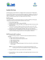
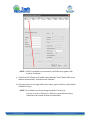
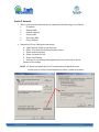
1
Earth Networks Weather Station Installation, Operation, and Maintenance Manual for Weather Stations with Serial Number starting with 09 to present EN.PM.UM13 20140227 Page 1 of 47 Copyright Copyright 2014, by Earth Networks, Inc. WeatherBug is a trademark of Earth Networks, Inc. All Rights Reserved. Information in this document is subject to change without notice and does not represent a commitment on the part of Earth Networks, Inc. The software described in this document is furnished under a license or non‐disclosure agreement. The software may be used or copied only in accordance with the terms of this agreement. It is against the law to copy Earth Networks, Inc., software onto magnetic tape, disk or any other medium for any purpose other than for the purchaser's personal use. DISCLAIMER The procedures, methods, and hardware outlined in this manual are intended to provide general guidelines for installing an Earth Networks Weather Station. Individual sites often have unique requirements that require materials and specifications that are beyond the scope of this manual. All procedures, methods, and hardware used to install an Earth Networks Weather Station must conform to all applicable building codes (local, state and national). Installation subcontractors are responsible for complying with all applicable codes. Buyer and/or installer provided hardware must be equivalent or better (according to industry standards) than that specified in the Earth Networks Weather Station installation manual. The buyer/installer is responsible for any damage caused by installation of the Earth Networks Weather Station. Furthermore, the buyer/installer is responsible for damage caused as a result of improper or faulty installation. THINK SAFETY FIRST! Special Note to Buyer/Installer: Contact Earth Networks ‐ Weatherbug Technical Support as soon as your Weather Station installation is complete. Earth Networks must remotely access your weather station's data to verify proper operation. Call Technical Support even if remote communications are not available at the time of installation. Earth Networks ‐ WeatherBug Technical Support: 800‐624‐4205 [email protected] EN.PM.UM13 20140227 Earth Networks Weather Station Page 2 of 47 Table of Contents COPYRIGHT ........................................................................................... 2 DISCLAIMER ............................................................................................ 2 INTRODUCTION ........................................................................................ 5 Weather Sensors Specifications .......................................................................... 5 SAFETY! ................................................................................................. 6 TYPICAL WEATHER STATION INSTALLATION ...................................................................... 7 FIRST THINGS ........................................................................................... 8 WEATHER STATION COMPONENTS .............................................................. 8 OUTDOOR COMPONENTS – WEATHER STATION ..................................................... 8 OUTDOOR COMPONENTS – OPTIONAL LIGHTNING SYSTEM ......................................... 9 INDOOR COMPONENTS............................................................................... 10 Earth Networks Network Appliance (ENNA) .............................................................. 10 FRONT OF ENNA .............................................................................................................10 Optional Auxiliary Temperature Sensor ..................................................................... 10 INSTALLATION ....................................................................................... 12 HARDWARE AND TOOL REQUIREMENTS ............................................................ 12 TOOLS REQUIRED .................................................................................... 13 SITE EVALUATION .................................................................................... 14 Finding the Best Location – Weather Station ............................................................. 14 Finding the Best Location – Weather Station & Lightning System .............................. 15 SITE SELECTION OPTIONS.................................................................................................16 Finding the Best Location – Indoor Equipment ........................................................... 16 INSTALLING OUTDOOR COMPONENTS .............................................................. 17 Installation of the Mast .............................................................................................. 18 Securing the Sensors to the Mast ............................................................................... 18 OPTIONAL LIGHTNING ANTENNA ASSEMBLY...................................................................20 OPTIONAL LIGHTNING GPS SENSOR ...............................................................................21 OPTIONAL LIGHTNING DSP .............................................................................................22 Connecting the Weather Sensor Cables...................................................................... 22 CONNECTING CABLES TO THE TRH ..................................................................................24 WIND SENSOR ORIENTATION ..........................................................................................25 EN.PM.UM13 20140227 Earth Networks Weather Station Page 3 of 47 DIGITAL SIGNAL PROCESSOR BOX 200’ DATA CABLE CONNECTION..............................26 LIGHTNING DSP, ANTENNA, & GPS CABLES ..................................................................27 LIGHTNING GPS CONNECTION .........................................................................................27 INSTALLING INDOOR COMPONENTS ................................................................. 30 Connecting the Indoor Weather Station Components ................................................ 31 INDOOR WEATHER STATION CONNECTIONS ...................................................................34 SYSTEM START‐UP .................................................................................. 35 DHCP NETWORK .................................................................................... 35 DHCP NETWORK WITH PROXY SERVER ............................................................ 35 STATIC IP NETWORK ................................................................................. 40 SYSTEM OPERATION ............................................................................... 44 NETWORK AND SOFTWARE CONFIGURATIONS ...................................................... 44 META DATA COLLECTION ......................................................................... 45 CALIBRATION......................................................................................... 45 MAINTENANCE ....................................................................................... 47 EN.PM.UM13 20140227 Earth Networks Weather Station Page 4 of 47 Introduction Congratulations on choosing an Earth Networks Weather Station, the premier automated weather system for educational and commercial applications. The Earth Networks Weather Station operates 24 hours daily, providing real‐time, up‐ to‐the‐second weather observations for 27 parameters, including: Temperature Relative humidity (dew point calculated) Barometric pressure Wind speed and direction Precipitation Weather Sensors Specifications Parameter Wind Speed Wind Direction * Range Standard 0 to 200 mph 0 to 352 deg. † ‐13○F to +150○F ‐31○F to –13○F ‐14○F to – 40○F 28.0”Hg to 32.0”Hg Relative Humidity (RH) Dew point calculation from Temp. and RH Rainfall Temperature Barometric Pressure ‡ Metric 0 to 320 kph Accuracy Resolution Standard +/‐ 2 mph Metric +/‐ 3 kph Standard 0.2 mph Metric 0.3 kph 0 to 352 deg. † +/‐ 3 deg. +/‐ 3 deg. 1 deg. 1 deg. ‐25○C to +65○C +/‐ 1○F +/‐ 0.5○C 0.1○F 0.05○C ‐35○C to –25○C +/‐ 2○F +/‐ 1○C 0.1○F 0.05○C ‐25○C to –40○C +/‐ 3○F +/‐ 1.5○C 0.1○F 0.05○C 948 hPa to 1084 hPa +/‐ 0.05”Hg +/‐ 1.7 hPa 0.01”Hg 1hPa 0 to 100% 0 to 100% +/‐ 3.5% +/‐ 3.5% 0.1% 0.1% Unlimited Unlimited +/‐ 1% @ 1”/hour +/‐ 1% @ 25 mm/hour .01” 0.25 mm * 8‐degree sector not covered † Wind average covers 0 to 360 degrees ‡ Barometric pressure is measured in inches of mercury (Hg) and hectopascal (hPa). EN.PM.UM13 20140227 Earth Networks Weather Station Page 5 of 47 Introduction (Continued) Your Earth Networks Weather Station is not difficult to install when all directions are followed carefully and the installation is well planned prior to assembly. Safety! While installation of the weather station is not particularly difficult, it does usually require installation on or near the rooftop, which presents some amount of risk. Installation must conform to national, state and local building code requirements; adhering to the most stringent guidelines. The weather station should only be installed by qualified individuals who are comfortable with being on a high ladder or rooftop and who are authorized by the site administration to perform the installation. To limit risk to self and property, this manual should be thoroughly read and understood before beginning installation. Stay as far away from other electrical wiring as possible. Never allow the mast, or any other item, to contact electrical wires or conduit. Injury or death could result. If desired, Earth Networks can complete the installation of your weather station. For an installation cost estimate please contact Earth Networks ‐ WeatherBug Technical Support at 800‐624‐4205 or email [email protected]. EN.PM.UM13 20140227 Earth Networks Weather Station Page 6 of 47 TYPICAL WEATHER STATION INSTALLATION Outdoor Equipment Wind Sensor Optional Lighting Antenna Sensor Shelter Rain Gauge Optional Lighting Digital Signal Processor (DSP) EN.PM.UM13 20140227 Earth Networks Weather Station Page 7 of 47 Getting Started First Things 1. READ THIS MANUAL THOROUGHLY It is very important that you read this entire manual prior to installation. If all instructions are followed carefully, installation of the weather station should be straightforward and problem free! 2. UNPACK AND INVENTORY WEATHER STATION COMPONENTS Carefully unpack and check all weather station components. Report any damaged or missing components to Earth Networks ‐ WeatherBug Technical Support immediately. 3. INSTALL WEATHER STATION 4. COMPLETE AND RETURN THE EARTH NETWORKS SITE DATA COLLECTION PACKET TO EARTH NETWORKS ‐ WEATHERBUG TECHNICAL SUPPORT Weather Station Components Outdoor Components – Weather Station The standard outdoor components of an Earth Networks Weather Station are as follows: Wind Sensor Sensor Shelter (with remote Temperature/Relative Humidity (TRH) Sensor mounted inside) Rain Gauge Data Cable The sensor suite of the weather station uses field grade sensors. The wind speed and direction sensor is an R.M. Young wind sensor.. The Rain Gauge is a standard tipping bucket that measures .01 inches of rain per tip. The Temperature/Relative Humidity (TRH) Sensor is a within a metal housing that is mounted inside the Sensor Shelter. Inside of the metal housing, the circuit board serves as an analog‐to‐digital (A‐D) converter. Digital conversion provides a high degree of accuracy and flexibility for distributing your weather station data. EN.PM.UM13 20140227 Earth Networks Weather Station Page 8 of 47 The Sensor Shelter (often referred to as an aspirated shelter) serves two primary purposes: Shields the TRH sensor from direct sunlight, which could yield inaccurate readings. The design minimizes heat build‐up by enabling air to flow through, resulting in "true" air temperature readings. Protects the TRH sensor from precipitation which could cause inaccurate readings as well as damage to the relative humidity sensor. The Data Cable transports data from the weather station's outdoor components to the Earth Networks Network Appliance (ENNA), located indoors. The Data Cable is UV‐rated and can be run along the weather station mast without conduit; however, conduit should be used to protect the cable when running it over the length of roof and into the building. If your building codes require different ratings of cable, please contact Earth Networks Weather Station Technical Support. NOTE: Cable should not be run across rooftop surfaces without protective conduit (not included). Outdoor Components – Optional Lightning System The Weather Station also has an optional lightning detection system that uses the Lightning Antenna with the Lightning Digital Signal Processor (DSP) to detect the unique radio frequency signature of static discharge caused by lightning. This system uses an integrated GPS Sensor that tracks time down to the level of a nanosecond in order to plot the geographic location with the highest accuracy. The time and sensor location are critical for integration into the Earth Networks Total Lightning Network (ENTLN). Each lightning sensor in the network works as part of a grouping of sensors to triangulate lightning stokes based on time and geographic location. The growing density of the Earth Networks Total Lightning Network allows greater resolution of lightning – allowing detection of both intracloud(IC) and cloud‐to‐ground (CG) lightning. EN.PM.UM13 20140227 Earth Networks Weather Station Page 9 of 47 Indoor Components The weather station indoor components are as follows: Earth Networks Network Appliance (ENNA) LCD Display Optional Auxiliary Temperature Sensor Earth Networks Network Appliance (ENNA) The ENNA is a microprocessor‐controlled computer with battery backup that uses your existing high‐speed internet connection to transmit weather data out to the Earth Networks WeatherBug network. It receives live input from the TRH sensor and optional Lightning equipment, processes and stores the data, and distributes it. The ENNA also houses the barometric pressure, indoor temperature, and optional auxiliary temperature sensors. FRONT OF ENNA The ENNA stores data at a default rate of once per hour. Up to four months of data at the one‐hour interval is stored in the ENNA. The internal battery backup of the ENNA prevents data loss during power outages for up to 10 hours when powering just the weather station, and 4 hours when powering the weather station in addition to the optional lightning equipment. The ENNA is designed to continue transmitting weather data during power outages as long as the network is operational. Once power is restored, the battery recharges and the ENNA will automatically resume sending current and historical data. Lightning data is not stored if the internet connection is not available. Optional Auxiliary Temperature Sensor The ENNA can also be connected to an Auxiliary Temperature Sensor. This wire can be run to measure temperature in aquariums, terrariums, or other areas. EN.PM.UM13 20140227 Earth Networks Weather Station Page 10 of 47 EN.PM.UM13 20140227 Earth Networks Weather Station Page 11 of 47 Installation Hardware and Tool Requirements The following hardware (equivalent or better quality) is required to install the Earth Networks Weather Station. If you are using an Earth Networks contracted installer, they will provide these materials. Required Parts Not Included Grounding cable and appropriate connectors Silicone caulk (to seal conduit and cable entry points into building) Mast o Galvanized Rigid Conduit (GRC) approximately 1/8 inch thickness (painted optional) o 1 ¼ inch/3.175 cm maximum outside diameter (at top of mast) o Mast can be comprised of two sections that total a minimum of 15 feet when assembled. A two‐section mast is recommended so the top section can be raised/lowered for easier installation and maintenance of the weather sensors. The bottom section should remain securely fastened. o (3) ¼‐20x2” grade 8 bolts with accompanying flat washer, lock washer, and nuts Mounting hardware (unistrut/steel channel with pipe clamps or heavy‐duty wall mounting brackets or non‐penetrating roof mount) Conduit for exterior Data Cable o Select conduit type based on your local building codes o 1 ¾ inch/4.445 cm outside diameter for weather station data (and camera) cable Grounding rod, if necessary Guy wire, if necessary to prevent top of mast from shaking EN.PM.UM13 20140227 Earth Networks Weather Station Page 12 of 47 Tools Required The following is a list of tools necessary to install the outdoor Earth Networks Weather Station and route the data cables into the building (actual tool requirements may vary depending on site configuration): 1. Compass 2. Step ladder (6‐8 feet/2 meter) 3. Level 4. Electric drill and masonry drill bits 5. Flathead and Phillips screwdrivers 6. Adjustable wrench 7. Wrenches 7/16 inch for Sensor Shelter nuts 5/16 inch for Wind Sensor nuts 3/8 inch for mast mounting brackets 1/2 inch for mast mounting brackets 9/16 inch for mast mounting brackets 5/8 inch for mast mounting brackets 13/16 inch for Lightning Digital Signal Processor Box nuts 8. Pliers 9. Wire cutters for cable ties EN.PM.UM13 20140227 Earth Networks Weather Station Page 13 of 47 Site Evaluation Before installing your weather station, conduct a thorough site evaluation to identify the best location for each component, including both the outdoor sensors and ENNA. All sites have restrictions. The accuracy of weather readings can depend on the weather station's location. The importance of this step cannot be overemphasized. A well‐planned installation eliminates almost all problems that could be encountered later. It may also prevent having to move part or all of the weather station. Finding the Best Location – Weather Station Locate your outdoor Earth Networks Weather Station in a location that takes all of the following into account: o In an open area o Clear of wind obstructions (especially for the prevailing wind direction) o Wind sensor must be a minimum of 10 feet/3 meter from roof o Sensor shelter must be a minimum of 8/2.5 meter feet from roof o Far away from ventilation and heat sources (minimum of 50 feet/15 meter) o Safe from vandalism o Close enough for cables to connect to indoor equipment (cables are minimum of 200 feet – additional lengths can be obtained in 100‐foot sections by contacting Earth Networks – WeatherBug Technical Support) EN.PM.UM13 20140227 Earth Networks Weather Station Page 14 of 47 Finding the Best Location – Weather Station & Lightning System For the optional Lightning System it is imperative that the weather station and lighting equipment is placed away from any noise/interference sources. The following are examples of noise sources that introduce false data into the lightning stream: o Power Lines (Especially High Tension Lines) o Motors (elevator, HVAC, exhaust/ventilation fans) o Anything that produces a spark o Multi bay Automotive Shop (engine spark plugs) o Welding Shop o Electric Fences o Fluorescent Lights o Stadium Lights o Gym roof (if light sensor is directly above gym) o Power Sub Stations o AM Radio Towers Placing the lightning system in a close proximity to any of the above mentioned systems could render the data from the lightning system unusable due to the amount of noise that is detected by the system. The mast must be grounded to an "earth" ground. Not grounding the system properly may also result in noise. The system must be grounded properly and located away from noise sources in order to clearly identify the unique radio frequency signature of static discharge caused by lightning. Example: HVAC Units generate Electrical / RF noise that can interfere with ENLS Performance. Based on the figure below, performance of sensors placed in red or dark red locations can significantly degrade the system’s ability to detect lightning signals above the HVAC noise. EN.PM.UM13 20140227 Earth Networks Weather Station Page 15 of 47 SITE SELECTION OPTIONS Locating Your Outdoor Earth Networks Weather Station Components Grassy Expanse Main Roof (1 Story) N 1 Extended Roof (2Stories) Prevailing Winds (Westerly in Much of U.S.) 2 Parking Lot Example Case: In the example above, Site 1 would be the preferred location for the mast and sensors. Site 1 has clear exposure to the prevailing winds and offers unobstructed wind measurement. Although Site 2 may offer a good location for prevailing winds, the extended roof would cause wind obstructions and the proximity to the parking lot could impact temperature readings. Wind measurements and potential obstructions should be given precedence when selecting an install location. Finding the Best Location – Indoor Equipment Locate your indoor Earth Networks equipment in a location that takes all of the following into account: EN.PM.UM13 20140227 Earth Networks Weather Station Page 16 of 47 o o o o Staffed location to ensure equipment is operating year‐round Year‐round power and internet connection A secure area where equipment will not be tampered with or turned off Adequate ventilation (equipment must not get over‐heated) Installing Outdoor Components There are three basic steps after ensuring the selected location fulfills site criteria: 1. Installation of the Mast 2. Securing the Sensors to the Mast 3. Connecting the Weather Sensor Cables and Grounding Data cables are not rated for movement below +15ºF/‐9ºC. Earth Networks does not recommend installing if the outdoor temperature is less than +15ºF/‐9ºC. EN.PM.UM13 20140227 Earth Networks Weather Station Page 17 of 47 Installation of the Mast IMPORTANT: Ensure that all mounting equipment and mast components meet the local building codes. The installer is responsible for choosing the best mounting for the location. Earth Networks requires the wind sensor to be 10 feet above the roofline and the sensor shelter to be 8 feet above the roofline, and both free of horizontal obstructions to ensure accurate data collection. The mounts must withstand harsh environments, including high winds. When determining the appropriate mounting for your installation, consider the following: Building material to which you will be mounting the mast (brick, block, siding, etc.) Roof overhang (unistrut/steel channel or mounting brackets must be placed so that the mast clears the roof) Secure the brackets to the building or secure the non‐penetrating roof mount on the roof. Install the bottom mounting in vertical alignment with the top mount. The mast must be completely vertical, use level to ensure alignment. Installing Outdoor Components Securing the Sensors to the Mast Follow these steps to secure the sensors to the mast so that the sensors are oriented properly and so that they meet the minimum height requirement above the roof surface. 1. If your mast is in more than one section, mount the sensors on the top section. The sections can be joined after securing the sensors and making the appropriate connections. 2. Mount the Rain Gauge by sliding its U‐bolt down the mast until it is low enough to be easily accessible for periodic cleanings. Finger‐tighten the U‐bolt but leave its cable loose for now. 3. Mount the Sensor Shelter by sliding its U‐bolt down the mast until it is two feet below the top. It should be 180◦ opposite the Rain Gauge so that it does not block the rain when raised. Finger‐tighten the U‐bolt making sure the EN.PM.UM13 20140227 Earth Networks Weather Station Page 18 of 47 shelter is upright so that precipitation cannot fall inside. Do not connect cables yet. EN.PM.UM13 20140227 Earth Networks Weather Station Page 19 of 47 Installing Outdoor Components 4. Carefully remove the Wind Sensor from its box and place it on the top of the mast so that the black junction box will face SOUTH when the mast is raised. Use a compass to verify location of black box. Securely tighten pipe clamp. Do not secure or connect the Wind Sensor cable at this point. 5. Adjust the sensor shelter to ensure it will be a minimum of 8 feet from the roof’s surface and is rotated so that it hangs over the ground or lowest roof. After ensuring proper alignment of equipment, tool tighten Sensor Shelter and Rain Gauge U‐bolts. If optional Lightning System was not purchased, please skip to Connecting the Weather Sensor Cables . 6. If optional Lightning System was purchased, assemble Lightning Antenna. Insert Antenna Cable and Ground Cable through the center of the Antenna Mount and push until cable comes out other end. Secure Antenna to top of mount and tool tighten. OPTIONAL LIGHTNING ANTENNA ASSEMBLY Antenna Mount & Antenna EN.PM.UM13 20140227 Feed Ground & Antenna Cable Secure Antenna to Mount Earth Networks Weather Station Page 20 of 47 7. If optional Lightning System was purchased, install Lightning Antenna onto the mast using 2 included Hose Clamps. Ensure that the Lightning Antenna is facing away from the building/rooftop and that the top of the lightning cylinder is level with the black box on the Wind Sensor. Attach the bottom Hose Clamp 2 inches/5 cm from the bottom of the Antenna and top Hose Clamp 2 inches/ 5 cm from the curve in the Antenna mast. Do not secure or connect the Lightning Antenna cable at this point. 8. If optional Lightning System was purchased, install black GPS Sensor onto the arm of the rain gauge using the grey double sided sticky tape included with the unit. Do not secure or connect the GPS cable at this point. OPTIONAL LIGHTNING GPS SENSOR EN.PM.UM13 20140227 Earth Networks Weather Station Page 21 of 47 9. If optional Lightning System was purchased, install Lightning Digital Signal Processor (DSP) as low as possible on the mast. Install the DSP on the mast so that accessing the internal components is feasible. Using the enclosed U‐bolts tool tighten the DSP box to the mast. OPTIONAL LIGHTNING DSP Connecting the Weather Sensor Cables Follow the steps below to connect the sensor cables to the Temperature/Relative Humidity (TRH) sensor (inside Sensor Shelter) and to connect the Data Cable to the ENNA. See the illustration Connecting Cables to the TRH. IMPORTANT: Do not damage or strain cables or connectors. One loose cable connection can cause system errors. 1. Loosen the mounting nuts and open the bottom plate of Sensor Shelter. 2. Route the Rain Gauge cable along the mast and through the opening in the bottom plate of the Sensor Shelter. Connect the blue end of the Rain Gauge cable to the RAIN connector at the right on the TRH. Insert the cable into the socket. Rotate the connector clockwise to lock it. (The RAIN connector has a blue washer that matches the blue band of the Rain Gauge cable.) EN.PM.UM13 20140227 Earth Networks Weather Station Page 22 of 47 3. Route the wind cable down the mast and through the opening in the bottom plate of the Sensor Shelter. Connect the yellow end of the wind cable to the WIND connector in the center on the TRH. Insert the cable into the socket. Rotate the connector clockwise to lock it. (The WIND connector has a yellow washer that matches the yellow band of the wind cable.) 4. Using the table below, select the proper Data Cable for your installation. Weather Station Only Weather Station & Lightning System Remove the 200' Data Cable from the Remove the 15' Lightning TRH Cable shipping box and remove wire ties. from the Lightning System box; this This is the cable that connects the cable will connect the TRH to the outdoor TRH to the indoor ENNA. Lightning DSP. Also remove the 200' 8 pin Data Cable from the Lightning System box; this cable will connect the Lightning DSP to the indoor ENNA. **200' 4 PIN Data Cable from the Weather Station box will not be used in this installation. Note: There are INDOOR and OUTDOOR labels on either end of the cable. 5. Route the 200' Data Cable labeled "OUTDOOR" or white banded end of the 15' Lightning TRH Cable through the side opening of the bottom plate and connect to the DATA connector at the left on the TRH. Insert the cable into the socket. Rotate the connector clockwise to lock it. (DATA connector has a white washer that matches the white band of the Data Cable.) EN.PM.UM13 20140227 Earth Networks Weather Station Page 23 of 47 6. Replace the bottom plate and tighten mounting nuts. CONNECTING CABLES TO THE TRH EN.PM.UM13 20140227 Earth Networks Weather Station Page 24 of 47 7. Secure the three cables below the Sensor Shelter connectors with a cable tie. Form a drip loop with the three cables (see Connecting Cables to the TRH). 8. Raise top section of mast and secure in place by inserting bolt(s) through aligned holes in top and bottom section of mast. Tool‐tighten the bolts. 9. Using a compass, confirm that the Wind Sensor’s black junction box is still pointing South. If necessary, lower mast and rotate Wind Sensor so it faces South (see below). 10. Verify Rain Gauge is 180◦ from Sensor Shelter and that Sensor Shelter is rotated to face over the ground. WIND SENSOR ORIENTATION If optional Lightning System was not purchased, please skip to step 20. 11. If optional Lightning System was purchased, verify that the Lightning Antenna is facing away from the building/rooftop and that the top of the lightning cylinder is level with the black box on the Wind Sensor. EN.PM.UM13 20140227 Earth Networks Weather Station Page 25 of 47 12. If optional Lightning System was purchased, verify that the 8 pin connector is visible on the side of the Lightning DSP. If it is not visible, use a 13/16 wrench or adjustable wrench to remove the black plastic nut and white washer from the box. Open the DSP box by unscrewing the 2 screws on the front right hand side of the box and push/pull the 4 pin connector back into the box. Making sure to align the flat portion of the connector with the flat portion of hole, shimmy the 8 pin connector through the opening. Once fully exposed, replace the white washer and finger tighten the black plastic nut. Gently tool tighten black nut to ensure that rubber washer is tightly in place to prevent water leaks. DIGITAL SIGNAL PROCESSOR BOX 200’ DATA CABLE CONNECTION 200’ Data Cable Connection TRH Cable Connection 4 Pin Male Connector **This configuration NOT covered in this manual. 8 Pin Male Connector 13. If optional Lightning System was purchased, route the red end of the 15' Lightning TRH Cable from the TRH to connect to the red connector at the lower side connection on the DSP Box. Insert the cable into the socket. Rotate the connector clockwise to lock it. EN.PM.UM13 20140227 Earth Networks Weather Station Page 26 of 47 14. If optional Lightning System was purchased, route the Lightning Antenna and GPS cable into the DSP box. Remove the water tight cable connector from bottom of DSP box by unscrewing. Push the Lightning Antenna cable and GPS cable through the cap and seal; work the plug through as the fit is tight. Push the cables into the bottom of the box allowing extra cable inside the box to make connections. Tighten the water tight cap and verify that the water tight seal tightens around the cables. LIGHTNING DSP, ANTENNA, & GPS CABLES Push through cap and seal Push into DSP Box Tighten cap & Check Seal 15. If optional Lightning System was purchased, connect the GPS Antenna cable to the socket on the elevated board inside the DSP Box. A click should be heard to indicate the connection is complete. LIGHTNING GPS CONNECTION Visual of GPS Socket on board in DSP Box EN.PM.UM13 20140227 Insert GPS Cable Earth Networks Weather Station Page 27 of 47 16. If optional Lightning System was purchased, connect the Lightning Antenna Cable into the jack on the board. 17. If optional Lightning System was purchased, connect the green grounding wire from the Lightning Antenna Cable to a U‐bolt on the Rain Gauge or Sensor Shelter. IMPORTANT: Grounding the Lightning Antenna to the mast and the mast to a secure ground in/on the building is necessary to protect the system from lightning strikes and to ensure the data is without noise and usable. 18. If optional Lightning System was purchased, connect the “OUTDOOR” end of the 200' 8 pin Data Cable from the Lightning System box to the 8 Pin Male Connector on the top side of the Lightning DSP Box. 19. The 200' Data Cable is now ready to be routed inside the building. Plan your cable route carefully. Make sure you know exactly where your cables will be before committing to your route. IMPORTANT: When routing cables and connectors, be careful not to damage or strain them. Run the Data Cable in conduit across the length of the building and around sharp corners (conduit not included). EN.PM.UM13 20140227 Earth Networks Weather Station Page 28 of 47 Installing Outdoor Components NOTES: Earth Networks recommends that you tape the connector ends together before running them inside the building (tape them fully to prevent damage or loosening individual wires). Do not cut connectors off. A single loose cable connection can cause system errors. Route Data Cable through 1¾ inch/4.445 cm outside diameter conduit on exterior of building (not included). Seal building hole and both ends of conduit using caulk/putty. Because the Earth Networks Weather Station Data Cable is UV‐rated, conduit is not required along the length of the mast, but should be used along the length of the building. Use the shortest route possible when running cables inside the building. The Data Cable ends at the ENNA. Excess cable should be coiled, tied and stored near the ENNA. 20. Securely attach a grounding cable to a metal part of the mast. The mast MUST be grounded to protect against lightning and static charge build‐up. The ground wire must be connected to an appropriate location (consult an electrician to ensure proper grounding). Where possible, the outdoor weather station components should be connected to its own independent ground and not share a ground with other equipment on the building. This grounding cable should follow the shortest path available to “earth” ground. Once a ground cable is connected to earth ground, you should measure the AC voltage between the ground cable and the mast before connecting the ground cable to the mast. The voltage should be 0.15 volts or less. Ground cable and installation must conform to all applicable local building codes. The mast must be grounded to an "earth" ground and not an existing electrical ground. The buyer/installer is EN.PM.UM13 20140227 Earth Networks Weather Station Page 29 of 47 responsible for this procedure and for ensuring that materials and methods conform to all applicable building codes. Installing Indoor Components The installation of all indoor components, including the ENNA and Digital Display, is covered in this section. EN.PM.UM13 20140227 Earth Networks Weather Station Page 30 of 47 Connecting the Indoor Weather Station Components 1. Open the ENNA by removing the 2 screws on each side of the side of the box. Lift off the lid to expose the circuit board. Before touching the circuit board, touch something metal to remove any static charge from your body; this will prevent damage to the board. Verify the appropriate jumper setting for your application: Installation Jumper Jumpers Illustration Switch Illustration Switch RBB‐09‐XXXX – BBB‐10‐2085 > RBB‐10‐2086 Weather Station **NO LIGHTNING EQUIPMENT Location WX TRH Weather Station & Lightning System – 8 Pin Data Cable LX 12V EN.PM.UM13 20140227 Earth Networks Weather Station Page 31 of 47 Installation Jumper Location Weather Station & Lightning System – 4 Pin Data Cable Used ***This Configuration is NOT covered in the manual LX Boost Jumpers Illustration RBB‐09‐XXXX – RBB‐10‐2085 Switch Illustration > RBB‐10‐2086 2. If the jumper is not in the appropriate location, relocate by pulling up on the jumper, moving to the appropriate pins, and pushing down gently. Or if the switch is not in the appropriate location, using a small paperclip, gently push the switch to the appropriate location. WARNING! Incorrectly assigning jumpers could result in damage to the equipment. Please verify correct alignment before powering unit. 3. Close the ENNA by replacing the lid and the 2 screws on each side of the ENNA. 4. Connect the Power Supply to the ENNA and ensure that power is in OFF position. 5. Find the end of Data Cable coming from your outdoor sensors. Place the connector so that the arrow is on top and connect it to the back of the ENNA, under the "Data Cable" label, being sure to match the appropriate 4 Pin or 8 Pin connection. 6. If applicable, connect the optional Auxiliary Temperature Sensor to the ENNA. EN.PM.UM13 20140227 Earth Networks Weather Station Page 32 of 47 EN.PM.UM13 20140227 Earth Networks Weather Station Page 33 of 47 7. Using the supplied Ethernet LAN Cable, plug the ENNA into your Local Area Network (LAN) or Internet Connection. 8. Plug the ENNA and Digital Display Power Supplies into the Power Strip. INDOOR WEATHER STATION CONNECTIONS EN.PM.UM13 20140227 Earth Networks Weather Station Page 34 of 47 System Start‐up Assuming that your site network is configured with a Dynamic Host Configuration Protocol (DHCP) where you are automatically assigned an IP address, your station is ready to be turned on. If your site network is currently using DHCP with a Proxy or Static IP addresses, please refer to the appropriate section below. DHCP Network Your ENNA should be connected and ready to be turned on (before powering any component, check to ensure that all connections are correct). 1. Turn on the Power Strip. 2. Using the “On/Off” switch, turn on the ENNA. 3. Five quick flashes of the status lights on the right hand side of the front of the ENNA will occur. 4. Verify that the Green LED lights on the back of the box, next to the “LAN” connection, are illuminated or flashing to indicate a live internet connection. 5. During the next minute the lights A, B, and C will come on in sequence. 6. Call Earth Networks ‐ Weather Station Technical Support at 800‐624‐4205 to confirm that data is being received and to ensure proper calibration. DHCP Network with Proxy Server 1. Using an existing computer on the site’s network to determine the Proxy Settings: a. Open Internet Explorer web browser. b. Select Tools from the Internet Explorer menu. c. Select Internet Options. d. Select Connections Tab. e. Select LAN Settings. f. Note the Proxy settings that appear in the Proxy Server Box at the bottom of the screen. NOTE: A‐F above are specifically for PC based Internet Explorer browser. Consult your browser’s documentation to follow a similar procedure. 2. Using the “On/Off” switch, turn on the Power to the ENNA. 3. Five quick flashes of the status lights on the right hand side of the front of the ENNA will occur. EN.PM.UM13 20140227 Earth Networks Weather Station Page 35 of 47 4. Verify that the Green LED lights on the back of box, next to the “LAN” connection, are illuminated or flashing to indicate a live internet connection. 5. Using another PC computer on the network (same subnet), download the latest WeatherBug Network Appliance Config program from http://download.earthnetworks.com/ and save it to the computer desktop. NOTE: If your current network setting does not allow downloads of .EXE files please download either the .ZIP file or the .EX file. If the .EX file is downloaded, rename the file extension to .EXE before using the file. 6. Double click on the WeatherBug Network Appliance Config program. 7. Using the WeatherBug Network Appliance Config program, select Search to seek out all BugBoxes on the network. NOTE: If the WeatherBug Network Appliance Config program was unable to find your ENNA select the Options button, change the number of seconds from 5 to 50, and select OK. Select Search again from the WeatherBug Network Appliance Config program. EN.PM.UM13 20140227 Earth Networks Weather Station Page 36 of 47 8. Select the MAC address for the ENNA. EN.PM.UM13 20140227 Earth Networks Weather Station Page 37 of 47 NOTE: If DHCP is enabled on your network, the ENNA may appear with another IP address. 9. Verify that the “Obtain an IP address automatically” and “Obtain DNS server address automatically” checkboxes are selected. 10. Using the boxes on the right side of the screen, type in the Proxy information obtained in Step 1. NOTE: Proxy address can be set using standard IP format (ex. 209.249.20.202) or DNS proxy. DNS proxy must be less than 75 characters and contain at least one period/dot. EN.PM.UM13 20140227 Earth Networks Weather Station Page 38 of 47 11. If your proxy requires a login, enter the User name and Password in the appropriate boxes. NOTE: The User name is limited to 50 characters and Password fields is limited to 20 characters. If no Username and Password are required leave fields blank. 12. Select the Change button from the center hand portion of the WeatherBug Network Appliance Config program. NOTE: After the Change button is selected the box will automatically restart and will take a few minutes to reappear on the network. 13. After approximately one minute, the A, B, and C LEDs should be solid green (no flashing). 14. Call Earth Networks – WeatherBug Weather Station Technical Support at 800‐ 624‐4205 to confirm that data is being received and to ensure proper calibration. EN.PM.UM13 20140227 Earth Networks Weather Station Page 39 of 47 Static IP Network 1. Talk to your Network Administrator to determine the following for the ENNA: IP Address Subnet Mask Default Gateway Primary DNS Secondary DNS Proxy Settings 2. Determine if Proxy Settings are necessary: a. Open Internet Explorer web browser. b. Select Tools from the Internet Explorer menu. c. Select Internet Options. d. Select Connections Tab. e. Select LAN Settings. f. Note any Proxy settings that appear in the Proxy Server Box at the bottom of the screen. NOTE: A‐F above are specifically for PC based Internet Explorer browser. Consult your browser’s documentation to follow a similar procedure. EN.PM.UM13 20140227 Earth Networks Weather Station Page 40 of 47 3. Using the “On/Off” switch, turn on the Power to the ENNA. 4. Five quick flashes of the status lights on the right hand side of the front of the ENNA will occur. 5. Verify that the Green LED lights on the back of the box, next to the “LAN” connection, are illuminated or flashing to indicate a live internet connection. 6. Using another PC computer on the network (same subnet), download the latest WeatherBug Network Appliance Config program from http://download.earthnetworks.com/ and save it to the computer desktop. NOTE: If your current network setting does not allow downloads of .EXE files please download either the .ZIP file or the .EX file. If the .EX file is downloaded, rename the file extension to .EXE before starting/opening the file. 7. Double click on the WeatherBug Network Appliance Config program. EN.PM.UM13 20140227 Earth Networks Weather Station Page 41 of 47 8. Using the WeatherBug Network Appliance Config program, select Search to seek out all BugBoxes on the network. NOTE: If the WeatherBug Network Appliance Config program was unable to find your ENNA select the Options button, change the number of seconds from 5 to 50, and select OK. Select Search again from the WeatherBug Network Appliance Config program. 9. Select the MAC address for the ENNA with the IP address of 192.168.237.227 (the default IP address for the ENNA). NOTE: If DHCP is enabled on your network, the ENNA may appear with another IP address. EN.PM.UM13 20140227 Earth Networks Weather Station Page 42 of 47 10. Using the boxes at the bottom of the screen, type in the following obtained in Steps 1 and 2: IP Address Mask Gateway Primary DNS Secondary DNS Proxy (if applicable) Proxy User name (if applicable) – NOTE: Limit of 50 characters Proxy Password (if applicable) – NOTE: Limit of 20 characters 11. Select the Change button from the lower center portion of the WeatherBug Network Appliance Config program. NOTE: After the Change button is selected the box will automatically restart and will take a moment to reappear on the network. 12. After a few minutes, the A, B, and C LEDs should be solid green (no flashing). 13. Call Earth Networks ‐ Weather Bug Weather Station Technical Support at 800‐ 624‐4205 to confirm that data is being received and to ensure proper calibration. EN.PM.UM13 20140227 Earth Networks Weather Station Page 43 of 47 System Operation Under normal conditions, your Earth Networks Weather Station should never be turned off. It is designed to operate 24 hours daily, every day, without operator input or assistance. Network and Software Configurations The ENNA requires that the Port 80 (http) and Port 9500 UDP outbound must be open for live weather data to transmit to the WeatherBug network. For sites with the optional Lightning System Port 9500 TCP must also be opened. If you require the specific IPs that this system will be sending too, please contact Earth Networks – WeatherBug Technical Support at 800‐624‐4205. FIREWALL: Your Network Administrator must be contacted to make changes to the firewall. Contact Earth Networks ‐ WeatherBug Technical Support at 800‐624‐ 4205 directly if there are questions. EN.PM.UM13 20140227 Earth Networks Weather Station Page 44 of 47 Meta Data Collection The metadata could be considered as important as the data collected from your weather station. Earth Networks collects metadata from all of our weather monitoring stations. This will help ensure that your weather station can continue to offer the highest quality weather information to your community. Your metadata will be used to ensure that your site's weather readings are as accurate as possible, as well as to verify its calibration and to detect any problems. Please print out the Earth Networks WeatherBug Site Data Collection Packet form from http://download.earthnetworks.com/and follow the instructions to complete the form. You will need to take and email 12 photos of your weather station installation following the directions with sample photos in the site data collection form. Calibration If your Earth Networks Weather Station is properly installed, only the time and barometric pressure will need to be calibrated upon initial connection. The barometric pressure sensor must be adjusted to compensate for altitude differences between the Earth Networks Weather Station production location and your installation site. The weather station time is typically pre‐set to US Eastern Standard Time (EST). All other calibrations are performed prior to shipment. The Earth Networks Weather Station is designed for remote calibration by Earth Networks – WeatherBug Technical Support via the Internet. You must properly configure your weather station for remote access to enable remote calibration. Part of the equation for barometric pressure is based on elevation. Earth Networks has already entered your general elevation. If possible, please provide your exact Latitude/Longitude and Elevation if you have this information available via a GPS system. If not, please confirm the address for the installation location so that an exact Latitude/Longitude and Elevation can be entered to ensure your site plots properly in the Earth Networks and WeatherBug products. Earth Networks ‐ WeatherBug Technical Support: 800‐624‐4205 [email protected] EN.PM.UM13 20140227 Earth Networks Weather Station Page 45 of 47 EN.PM.UM13 20140227 Earth Networks Weather Station Page 46 of 47 Maintenance Under normal conditions, your Earth Networks Weather Station will require very little maintenance. Most maintenance issues can be evaluated and diagnosed remotely by the Earth Networks ‐ WeatherBug Quality Control Team. All components are “Plug‐ and‐Play”. Defective sensors can be removed simply by disconnecting them from the cable connections. The Rain Gauge normally requires the most maintenance. Check the Rain Gauge every three months or any time that readings appear to be lower than they should be. Clear any debris clogging the inlet from passing liquid precipitation into the tipping bucket. Looking down into the top of the Rain Gauge you will see that it is funnel‐shaped and, at the bottom of the funnel, there is a small hole. This hole must be clear for the gauge to measure rainfall accurately. Bamboo skewers or a similar instrument are excellent for clearing the inlet of debris. For video instructions on cleaning the Rain Gauge, please visit: http://download.earthnetworks.com/ Earth Networks ‐ WeatherBug Technical Support: 800‐624‐4205 [email protected] EN.PM.UM13 20140227 Earth Networks Weather Station Page 47 of 47