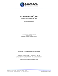
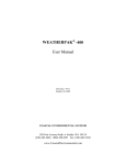
1
Weather Station Installation, Operation, and Maintenance Manual November 2004 AWS-WXN-60003.001 Version 1.0, Release 5 AWS Part # (7001) Weather Station Manual Copyright Copyright 2003, by AWS Convergence Technologies, Inc. WeatherBug is a trademark of AWS Convergence Technologies, Inc. All Rights Reserved. Information in this document is subject to change without notice and does not represent a commitment on the part of AWS Convergence Technologies, Inc. The software described in this document is furnished under a license or non-disclosure agreement. The software may be used or copied only in accordance with the terms of this agreement. It is against the law to copy AWS Convergence Technologies, Inc., software onto magnetic tape, disk or any other medium for any purpose other than for the purchaser's personal use. Note: This equipment has been tested and found to comply with the limits for a Class A digital device, pursuant to Part 15 of the FCC rules. These limits are designed to provide reasonable protection against harmful interference when the equipment is operated in a commercial environment. This equipment generates, uses and can radiate radio frequency energy. If not installed and used in accordance with the instruction manual, may cause harmful interference to radio communications. For Technical Support relating to this WeatherBug product, call 800-6244205 or email [email protected]. AWS-WXN-60003.001 Version 1.0, Release 5 -2- November 2004 Weather Station Manual DISCLAIMER The procedures, methods and hardware outlined in this manual are intended to provide general guidelines for installing a WeatherBug Weather Station. Individual sites often have unique requirements that require materials and specifications that are beyond the scope of this manual. All procedures, methods and hardware used to install a WeatherBug Weather Station must conform to all applicable building codes (local, state and national). Installation subcontractors are responsible for complying with all applicable codes. Buyer- and/or installer-provided hardware must be equivalent or better (according to industry standards) than that specified in the WeatherBug installation manual. The buyer/installer is responsible for any damage caused by installation of the WeatherBug weather station. Furthermore, the buyer/installer is responsible for damage caused as a result of improper or faulty installation. THINK SAFETY FIRST! READ THE GETTING STARTED SECTION OF THIS MANUAL FOR HELPFUL SAFETY TIPS. Special Note to Buyer/Installer: Contact WeatherBugTM Technical Support as soon as your WeatherBugTM weather station installation is complete. WeatherBugTM must remotely access your weather station's data to verify proper operation. Call WeatherBugTM Technical Support even if remote communications are not available at the time of installation. WeatherBugTM Weather Station Technical Support: 800-624-4205 [email protected] Monday - Thursday -- 8:00am-7:00pm EST Friday -- 8:00am-5:00pm EST AWS-WXN-60003.001 Version 1.0, Release 5 -3- November 2004 Weather Station Manual Table of Contents COPYRIGHT.................................................................................................... 2 DISCLAIMER ................................................................................................... 3 INTRODUCTION............................................................................................. 6 Weather Sensors Specifications........................................................ 6 TYPICAL WEATHER STATION INSTALLATION ............................................... 8 GETTING STARTED ........................................................................................ 9 SAFETY!......................................................................................................... 9 FIRST THINGS ............................................................................................... 10 WEATHER STATION COMPONENTS............................................................. 11 OUTDOOR COMPONENTS ............................................................................... 11 STANDARD OUTDOOR COMPONENTS ..................................................... 12 INDOOR COMPONENTS .................................................................................. 13 INDOOR COMPONENTS ........................................................................ 13 The Master Control Unit (MCU).............................................................................14 FRONT OF MASTER CONTROL UNIT (MCU) ............................................ 14 Digital Display (Optional) ......................................................................................15 THE DIGITAL DISPLAY .......................................................................... 15 COMPUTER CONNECTIONS .............................................................................. 15 INSTALLATION............................................................................................. 16 HARDWARE AND TOOL REQUIREMENTS ............................................................. 16 TOOLS REQUIRED .......................................................................................... 17 SITE EVALUATION.......................................................................................... 18 Finding the Best Location ......................................................................................18 SITE SELECTION OPTIONS ..................................................................... 19 INSTALLING OUTDOOR COMPONENTS............................................................... 19 Installation of the Mast..........................................................................................20 TYPICAL BUILDING MOUNT ................................................................... 21 TYPICAL WALL MOUNT BRACKET ........................................................... 22 Securing the Sensors to the Mast ...........................................................................23 Connecting the Weather Sensor Cables..................................................................24 CONNECTING CABLES TO THE TRH........................................................ 25 WIND SENSOR ORIENTATION ................................................................ 26 INSTALLING INDOOR COMPONENTS .................................................................. 28 Connecting the Indoor Weather Station Components..............................................28 FRONT AND REAR OF MASTER CONTROL UNIT (MCU).............................. 29 AWS-WXN-60003.001 Version 1.0, Release 5 -4- November 2004 Weather Station Manual POWER AND COMMUNICATIONS CONNECTIONS ....................................... 30 SOFTWARE INSTALLATION.......................................................................... 31 COMPUTER SPECIFICATIONS ............................................................................ 31 OBTAINING THE SOFTWARE............................................................................. 31 SYSTEM START-UP AND OPERATION .......................................................... 32 NETWORK AND SOFTWARE CONFIGURATIONS .................................................... 33 IP Ranges ............................................................................................................33 MacMET Server ...................................................................................................33 WeatherStreamer ................................................................................................33 WeatherBug Camera (Optional)...........................................................................33 HOMELAND SECURITY SITE DATA COLLECTION ........................................ 35 SAMPLE PACKING LIST ......................................................................... 35 CALIBRATION............................................................................................... 36 TROUBLESHOOTING.................................................................................... 37 Troubleshooting Chart................................................................... 37 WEATHERBUG ACHIEVE (FOR SCHOOLS ONLY).......................................... 38 MAINTENANCE ............................................................................................ 39 AWS-WXN-60003.001 Version 1.0, Release 5 -5- November 2004 Weather Station Manual Introduction Congratulations on choosing a WeatherBug Weather Station, the premier automated weather system for educational and commercial applications. The WeatherBug Weather Station operates 24 hours daily, providing real-time, up-to-thesecond weather observations for 27 real-time parameters, including: • • • • • Temperature Relative humidity (dew point calculated) Barometric pressure Wind speed and direction Precipitation Weather Sensors Specifications Parameter Wind Speed Wind Direction * Temperature Barometric Pressure ‡ Relative Humidity (RH) Dew point calculation from Temp. and RH Rainfall * † ‡ Range Accuracy Resolution 0 to 200 mph 0 to 352 deg. † -30F to +140F -40F to –30F -65F to –40F 17.5”Hg to 32.0”Hg +/- 2 mph +/- 3 deg. +/- 1F +/- 2F +/- 3F +/- 0.05”Hg 0.2 mph 0.1 deg. 0.1F 0.1F 0.1F 0.0035”Hg 0 to 100% +/- 2% 0.1% Unlimited +/- 2% @ 1”/hour .01” 8-degree sector not covered Wind average covers 0 to 360 degrees Barometric pressure is measured in inches of mercury (Hg). Metric equivalents are available through the included software AWS-WXN-60003.001 Version 1.0, Release 5 -6- November 2004 Weather Station Manual Introduction (Continued) Your WeatherBug Weather Station is not difficult to install when all directions are followed carefully and the installation is well planned prior to assembly. Installation is similar to that of an outdoor TV antenna (the weather station's outdoor mast and weather sensors) that you connect to an indoor VCR (the weather station's master control unit) and a TV set (the weather station's Digital Display and computer). A typical weather station set-up is shown in “Typical Weather Station Installation,” page 8. For Educational Institutions Only Through the purchase of a WeatherBug Weather Station, your school has joined the WeatherBug Achieve educational technology program, an integrated network of more than 6,000 school-based WeatherBug Weather Stations. Through the Web-based application, WeatherBug Achieve (page 38), you can access real-time and historical data from any participating WeatherBug Achieve school. AWS-WXN-60003.001 Version 1.0, Release 5 -7- November 2004 Weather Station Manual TYPICAL WEATHER STATION INSTALLATION AWS-WXN-60003.001 Version 1.0, Release 5 -8- November 2004 Weather Station Manual Getting Started Safety! • While installation of the weather station is not particularly difficult, it does usually require installation on or near the rooftop, which presents some amount of risk. • Installation must conform to national, state and local building code requirements; adhering to the most stringent guidelines. • The weather station should only be installed qualified individuals who are comfortable with being on a high ladder or rooftop and who are authorized by the site administration to perform the installation. • To limit risk to self and property, this manual should be thoroughly read and understood before beginning installation. • Stay as far away from other electrical wiring as possible. Never allow the mast, or any other item, to contact electrical wires or conduit. Injury or death could result. If desired, WeatherBug can contract the installation of your weather station. For an installation cost estimate please contact WeatherBug Technical Support at (800) 624-4205 or email [email protected]. AWS-WXN-60003.001 Version 1.0, Release 5 -9- November 2004 Weather Station Manual Getting Started (Continued) First Things 1. READ THIS MANUAL THOROUGHLY It is very important that you read this entire manual prior to installation. If all instructions are followed carefully, installation of the weather station should be straightforward and problem free! 2. SELECT WEATHER STATION COMPUTER Your WeatherBug Weather Station supports either a PC or Macintosh computer. The preferred computer is a dedicated PC, used only for the weather station, that is a Pentium 2, 3, or 4 computer with 128 MB RAM, and Windows 2000 or greater. Dedicating a computer for use solely by the weather station will significantly reduce the number of problems you have with the station. For more information on computer specifications see page 31. 3. UNPACK AND INVENTORY WEATHER STATION COMPONENTS Carefully unpack and check all weather station components using the packing list on the outside of your shipping container. Report any damaged or missing components to WeatherBug immediately. 4. BEGIN INSTALLATION 5. COMPLETE AND RETURN THE HOMELAND SECURITY SITE DATA PACKET TO WEATHERNETTM After completing installation, please complete and return the enclosed Homeland Security Site Data Packet as soon as possible. AWS-WXN-60003.001 Version 1.0, Release 5 - 10 - November 2004 Weather Station Manual Weather Station Components Outdoor Components The outdoor components (see “Standard Outdoor Components,” on page 12) of a standard WeatherBug Weather Station are: • Sensor Shelter (with Remote Temperature/Relative Humidity (TRH) Sensor mounted inside) • Wind Sensor • Rain Gauge • Data Cable The Weather Station's sensor suite uses accurate and rugged sensors. The wind speed and direction sensor is an R.M. Young wind vane, widely acknowledged to be one of the top Wind Sensors available. The Rain Gauge is a standard tipping bucket that measures .01 inches of rain per tip. Remote Temperature/Relative Humidity (TRH) Sensor is a metal box about the size of a deck of cards that is mounted inside the Sensor Shelter. The circuit board within the TRH serves as an analog-to-digital (A-D) converter. Digital conversion provides a high degree of accuracy and flexibility for distributing your weather station data. The Sensor Shelter (often referred to as a convection aspirated shelter) serves two primary purposes: • It shields the remote TRH sensor from direct sunlight, which could yield inaccurate readings (the design minimizes heat build-up by enabling natural air currents to flow through it, resulting "true" air temperature readings). • Second, it protects the remote TRH sensor from rain, ice and snow, which could also produce inaccurate readings as well as cause damage to the relative humidity sensor. Plenum-rated data cable* transports data from the weather station's outdoor components to the master control unit (MCU), located indoors. Conduit (not included) is not required if the cable is run indoors in a building plenum. * Plenum-rated data cables are UL listed as having adequate fire resistance and low smoke-producing characteristics for installations without conduit in ducts, plenums and other spaces used for environmental (shared) air. NOTE: Cable should not be installed on rooftop surfaces without protective conduit (not included). AWS-WXN-60003.001 Version 1.0, Release 5 - 11 - November 2004 Weather Station Manual STANDARD OUTDOOR COMPONENTS AWS-WXN-60003.001 Version 1.0, Release 5 - 12 - November 2004 Weather Station Manual Indoor Components The weather station indoor components are: • Master control unit (MCU) • Auxiliary temperature sensor • Optional Digital display(s) • Computer running WeatherStreamer or MacMET Server software (See the section on Software Installation on page 31) • WeatherBug Achieve * (Web-based teaching application that includes interactive lesson plans, graphing, mapping, live weather data display and more) * FOR SCHOOLS ONLY INDOOR COMPONENTS AWS-WXN-60003.001 Version 1.0, Release 5 - 13 - November 2004 Weather Station Manual Indoor Components (Continued) The Master Control Unit (MCU) The master control unit (MCU) is a microprocessor-controlled computer with a real-time clock. It receives live input from the remote TRH sensor, processes and stores the data in its non-volatile electronic memory, and distributes it. Data can be sent to three output channels simultaneously. The MCU also houses the barometric pressure, indoor temperature, and auxiliary temperature sensors. The signals from the remote TRH sensor come through the main data cable (the blue cable) into the MCU. It is essential that there are no sharp bends or crimps in the cable. The cable should be protected (stabilized) where it passes through the exterior wall. The MCU's first output is to the optional Digital Display. The second is to the computer (using a serial port on the PC or Macintosh) and a third to a modem (if required). The WeatherStreamer/MacMET software allows real-time weather data to be sent and accessed via the Internet and displayed on the computer. FRONT OF MASTER CONTROL UNIT (MCU) The MCU stores data at a default rate of once per hour. This rate may be re-set to intervals of between one minute and up to one hour. Up to four months of data at the one-hour interval is stored in the MCU. The MCU's internal battery backup prevents data loss during power outages for up to 16 hours. Once power is restored, the battery automatically recharges. An uninterruptible power supply (UPS) and power strip are included to provide additional battery backup (5 – 10 minutes) as well as power surge protection. AWS-WXN-60003.001 Version 1.0, Release 5 - 14 - November 2004 Weather Station Manual Indoor Components (Continued) Digital Display (Optional) The optional Digital Display receives live data every second from the MCU and displays it on several large digital LEDs. Housed in an attractive oak case, the display shows daily highs, lows and rates of change. For more information, see the Digital Display User's Manual. THE DIGITAL DISPLAY Computer Connections The MCU will be connected to a PC or Macintosh through a serial cable. AWS-WXN-60003.001 Version 1.0, Release 5 - 15 - November 2004 Weather Station Manual Installation Hardware and Tool Requirements The following hardware (equivalent or better quality) is required to install the WeatherBug Weather Station. If you are using a contracted installer, they will provide these materials. Required Parts Not Included • • • • Mounting hardware (heavy-duty wall mounting brackets) Grounding cable and appropriate connectors Silicone caulk (to seal conduit and cable entry points into building) Mast o Galvanized Rigid Conduit (GRC) approximately 1/8 inch thickness (painted optional) o 1 ¼ inch maximum outside diameter (at top of mast) o Must be approximately 15 feet total length o Mast can be comprised of two sections that total 15 feet. A two-section mast is recommended so the top section can be raised/lowered for easier installation and maintenance of the weather sensors. The bottom section should remain securely fastened. o The top section should be secured to the bottom section using two bolts. • • Grounding rod, if necessary (unit MUST have an “earth” ground) Conduit for exterior data cable o Select conduit type based on your state's building codes o 1 ¾ inch outside diameter for weather station data (and camera) cable For your convenience, specifications on the parts and tools you will need can be found at: http://downloads.aws.com/manuals/partsrequired.pdf AWS-WXN-60003.001 Version 1.0, Release 5 - 16 - November 2004 Weather Station Manual Tools Required The following is a list of tools necessary to install the outdoor WeatherBug Weather Station and route the data cables into the building (actual tool requirements may vary depending on site configuration): 1. 2. 3. 4. 5. 6. 7. Compass Step ladder (6-8 feet) Level Electric drill and masonry drill bits Flathead and Phillips screwdrivers Adjustable wrench Wrenches • 7/16 inch for Sensor Shelter nuts • 3/8 inch for mast mounting brackets • 1/2 inch for mast mounting brackets • 9/16 inch for mast mounting brackets • 5/8 inch for mast mounting brackets 8. Pliers 9. Socket set (optional) 10. Wire cutters for cable ties AWS-WXN-60003.001 Version 1.0, Release 5 - 17 - November 2004 Weather Station Manual Site Evaluation Before installing your weather station, conduct a thorough site evaluation to identify the best location for each component, including the outdoor sensor suite, MCU, and Digital Display. This requires working with someone who has access to all grounds, including the roof. The importance of this step cannot be overemphasized! A well-planned installation eliminates almost all problems that could be encountered later. It may prevent having to move part or all of the station. The placement of each component is dependent, to some extent, on the placement of the other components. All sites have restrictions. Care must be taken to select the best location for each component. The accuracy of weather readings can depend on the weather station's location. This section provides information to help you select the best location possible. Finding the Best Location Locate your outdoor WeatherBug Weather Station in a location that takes all of the following into account: o In an open area o Clear of wind obstructions (especially for the prevailing wind direction) o Wind Sensor must be a minimum of 10 feet from roof o Sensor Shelter must be a minimum of 8 feet from roof o Far away from ventilation and heat sources o Safe from vandalism o Away from large, asphalt parking lots o Close enough for cables to connect to indoor equipment (cables are minimum of 200 feet – additional lengths may be purchased in 100-foot sections) See “Site Selection Options” on page 19 for an overhead layout of a typical installation for the outdoor components. Locate your indoor WeatherBug equipment in a location that takes all of the following into account: o Staffed location to ensure equipment is operating year-round o Year-round power and Internet connection o Close to computer and phone for technical support o A secure area where equipment will not be tampered with or turned off o Adequate ventilation (equipment must not get over-heated) AWS-WXN-60003.001 Version 1.0, Release 5 - 18 - November 2004 Weather Station Manual SITE SELECTION OPTIONS Locating Your Outdoor WeatherBug Weather Station Components Grassy Expanse Main Roof (1 Story) N 1 Gymnasium Roof (2Stories) Prevailing Winds (Westerly in Much of U.S.) 2 Parking Lot Example Case: In the example above, Site 1 would be the preferred location for the mast and sensors. Site 1 has clear exposure to the prevailing winds and offers unobstructed wind measurement. Although Site 2 may offer a good location for prevailing winds, the gymnasium roof would cause wind obstructions and the proximity to the parking lot could impact temperature readings. Wind measurements should be given precedence when selecting an install location. Installing Outdoor Components Installing outdoor weather station components is similar to installing an outdoor TV antenna. There are three basic steps after ensuring the chosen location fulfills site criteria (see “Site Evaluation,” page 18): 1. Installation of the Mast 2. Securing the Sensors to the Mast 3. Connecting the Weather Sensor Cables and Grounding Data Cables are not rated for movement below +14ºF. Do NOT install the weather station if the outdoor temperature is less than 15º F. AWS-WXN-60003.001 Version 1.0, Release 5 - 19 - November 2004 Weather Station Manual Installation of the Mast IMPORTANT: Ensure that all mounting brackets and mast components meet the local building codes and work with the installation site you have chosen. Properly securing the mounting brackets and mast is critical for a successful installation. The mounts must withstand harsh environments, including high winds. When determining the appropriate mounting brackets for your installation, consider the following: • Building material to which you will be mounting the mast (e.g., brick, block, siding, etc.) • Roof overhang (mounting brackets must be placed so that the mast clears the roof) Secure the brackets to the building as shown in “Typical Building Mount,” page 21. Install the bottom mounting bracket in vertical alignment with the top bracket. The mast must be completely vertical. Ensuring vertical alignment is critical! AWS-WXN-60003.001 Version 1.0, Release 5 - 20 - November 2004 Weather Station Manual TYPICAL BUILDING MOUNT 6″ From Bottom of Mast It is recommended that you use a heavy-duty mounting bracket similar to that shown in “Typical Wall Mount Bracket,” page 22. Brick walls require anchors in addition to the lag screws. Block or thin wall siding may require a toggle. Your installer is responsible for selecting the appropriate industry standard or better mounting hardware, which should be available in any local hardware or electrical supply store. AWS-WXN-60003.001 Version 1.0, Release 5 - 21 - November 2004 Weather Station Manual TYPICAL WALL MOUNT BRACKET AWS-WXN-60003.001 Version 1.0, Release 5 - 22 - November 2004 Weather Station Manual Installing Outdoor Components (Continued) Follow these steps to secure the mast to the wall mounting brackets: 1. Loosen the bolts on the outside of the wall mounting brackets so shorter section of the mast can be inserted into the slots on the brackets (do not loosen the screws that hold the brackets to the wall). 2. Insert the mast into and through both wall mounting bracket slots and tool tighten bolts. Securing the Sensors to the Mast Follow these steps to secure the sensors to the mast so that the sensors are oriented properly and so that they meet the minimum required height above the roof surface (refer to “Standard Outdoor Components,” page 12): 1. If your mast is in more than one section, mount the sensors on the top section. The sections can be joined after securing the sensors and making the appropriate connections. 2. Tilt the mast so that the sensor U-bolts can slide down over the top. 3. Mount the Rain Gauge by sliding its U-bolt down the mast until it is approximately five feet below the top. Finger-tighten the U-bolt, but leave its cable loose for now. 4. Mount the Sensor Shelter by sliding its U-bolt down the mast until it is two feet below the top. It should be directly opposite the Rain Gauge so that it does not block the rain when raised. Finger-tighten the U-bolt making sure the shelter is upright so that rain and snow cannot fall inside. Do not connect cables yet. 5. Remove the orientation ring (circular piece of plastic with a pipe clamp) from the Wind Sensor box. Slide the orientation ring down the mast approximately six inches and tighten it enough to prevent it from moving. Carefully remove the Wind Sensor from its box (its cable is already attached) and place it on the top of the mast so that the black junction box will face SOUTH when the mast is raised. Securely tighten pipe clamp. Loosen orientation ring and slide it up so that its key fits into the Wind Sensor's notch, then tighten ring (the orientation ring allows the Wind Sensor to be removed for maintenance without losing direction reference). Do not secure or connect the Wind Sensor cable at this point. AWS-WXN-60003.001 Version 1.0, Release 5 - 23 - November 2004 Weather Station Manual Installing Outdoor Components (Continued) Connecting the Weather Sensor Cables Follow the steps below to connect the sensor cables to the Remote Temperature/Relative Humidity (TRH) sensor (inside Sensor Shelter) and to connect the data cable from the TRH to the master control unit (MCU) (see “Connecting Cables to the TRH,” page25): IMPORTANT: Do not damage or strain cables or connectors. One loose cable connection can cause system errors. 1. Remove 200' data cable from the shipping box and remove wire ties. This is the blue cable that connects the TRH to the MCU. Note INDOOR and OUTDOOR labels on either end of the cable. 2. Loosen the mounting (“thumb”) nuts and open bottom plate of Sensor Shelter. 3. Route the data cable labeled "OUTDOOR" through the side opening of the bottom plate and connect to the DATA connector at the left on the TRH. Insert the cable into the socket. Rotate the connector clockwise to lock it. (DATA connector has a white washer that matches the white end of the data cable.) 4. Route the wind cable down the mast until it is beneath the Sensor Shelter, through the opening in the bottom plate and connect the yellow end of the wind cable to the WIND connector in the center on the TRH. (The WIND connector has a yellow washer that matches the yellow end of the wind cable.) 5. Route the Rain Gauge cable up the mast until it is beneath the Sensor Shelter, through the opening in the bottom plate and connect the blue end of the Rain Gauge cable to the RAIN connector at the right on the TRH. (The RAIN connector has a blue washer that matches the blue end of the Rain Gauge cable.) 6. Replace bottom plate and tighten mounting (“thumb” nuts). AWS-WXN-60003.001 Version 1.0, Release 5 - 24 - November 2004 Weather Station Manual CONNECTING CABLES TO THE TRH AWS-WXN-60003.001 Version 1.0, Release 5 - 25 - November 2004 Weather Station Manual Installing Outdoor Components (Continued) 7. Secure the three cables below the Sensor Shelter connectors with a wire tie. Form a drip loop with the three cables (see “Connecting Cables to the TRH,” page25). Tighten the cable strain relief bracket. 8. Secure the WIND, RAIN and DATA cables to the mast with wire ties. 9. Raise top section of mast and secure in place by inserting bolt(s) through aligned holes in top and bottom section of mast. Tool-tighten the bolts. 10. Using the compass, confirm that the Wind Sensor’s black junction box is still pointing south. If necessary, lower mast and rotate Wind Sensor so it faces south (see below). WIND SENSOR ORIENTATION 11. The 200' data cable is now ready to be routed inside the building. Plan your cable route carefully. Make sure you know exactly where your cables will be before committing to your route. IMPORTANT: When routing cables and connectors, be careful not to damage or strain them. All outdoor cabling must be run in conduit (not included). AWS-WXN-60003.001 Version 1.0, Release 5 - 26 - November 2004 Weather Station Manual Installing Outdoor Components (Continued) NOTES: • WeatherBug recommends that you tape the connector ends together before running them inside the building (tape them fully to prevent damage or loosening individual wires). Do not cut connectors off. A single loose cable connection can cause system errors. • Conduit must be used with cable that is routed to the building exterior. Check local building codes for specific requirements. • Route data cable through 1¾ inch outside diameter conduit on exterior of building then down into building through an opening at least 1½ inches in diameter (conduit stops at opening). • Seal building hole and both ends of conduit using caulk/putty. • Because the WeatherBug Weather Station data cable is plenum-rated, conduit is not required indoors in ceiling plenum areas. Use conduit if cable is run in exposed areas within your building. Route through the ceiling if possible. • Use the shortest route possible when running cables inside the building. • The data cable ends at the MCU. Excess cable should be coiled, tied and stored near the MCU. 12. Securely attach a grounding cable to a metal part of the mast. The mast MUST be grounded to protect against lightning and static charge build-up. The ground wire must be connected to an appropriate location (consult a school or district electrician to ensure proper grounding). IMPORTANT: Ground cable and installation must conform to all applicable local building codes. The mast must be grounded to an "earth" ground. The buyer/installer is responsible for this procedure and for ensuring that materials and methods conform to all applicable building codes. AWS-WXN-60003.001 Version 1.0, Release 5 - 27 - November 2004 Weather Station Manual Installing Indoor Components The final step is the installation of all indoor components, including the MCU, Digital Display and computer. Connecting the Indoor Weather Station Components 1. Connect all power, display, computer cables and the auxiliary temperature sensor to the master control unit (MCU) and ensure that power is in OFF position (see “Front and Rear of Master Control Unit – MCU” and “Power and Communications Connections” on pages 29 and 30). 2. Find the end of data cable coming from your outdoor sensors (blue cable). Place the connector so that the arrow is on top and connect it to the back of the MCU, under the "Sensor Net" label (be sure the connector is positioned properly). 3. If applicable, connect other end of 25-foot display cable cord (“telephone line”) to the Digital Display (See the Digital Display Operations Manual for Digital Display installation instructions). 4. Assemble the UPS battery according to instructions provided with the UPS and plug it into wall outlet. 5. Plug the power strip into the UPS. 6. Plug the MCU and the Digital Display power supplies into the power strip. 7. Plug the computer power cord into back of the UPS. 8. Connect the computer to the MCU using the supplied computer cable. NOTE: Some Macs require an adapter not sold by WeatherBug. NOTE: Please see “Software Installation” on page 31 for information about receiving software if you are using an existing or donated computer. AWS-WXN-60003.001 Version 1.0, Release 5 - 28 - November 2004 Weather Station Manual FRONT AND REAR OF MASTER CONTROL UNIT (MCU) AWS-WXN-60003.001 Version 1.0, Release 5 - 29 - November 2004 Weather Station Manual POWER AND COMMUNICATIONS CONNECTIONS AWS-WXN-60003.001 Version 1.0, Release 5 - 30 - November 2004 Weather Station Manual Software Installation If an entire weather station camera package was purchased from WeatherBug, all required software is pre-installed. However, AWS realizes that, in some cases, existing or donated computers are used. Computer Specifications If you are using an existing or donated computer, it should meet or exceed the following specifications: Equipment Computer Preferred PC - Pentium 2, 3, 4 RAM Operating System 128 MB Windows 2000 Pro, XP Pro Minimum PC - Pentium Mac 64 MB Windows 98, ME, NT Real time Internet Connection Dedicated Computer T-1, Cable, DSL T-1, Cable, DSL Computer only used to transmit weather station data (and camera data if applicable) Computer only used to transmit weather station data (and camera data if applicable) Obtaining the Software Both the PC and Macintosh computer software is included on your Weather Station Resource CD. The installation instructions for MAC Weather Server and PC Weather Streamer are also reside on the Resource CD. A straight through serial connector computer cable which connects the MCU to the computer is also included in your package. Macintosh users will need to use the straight through serial connector with the Mac adaptor. Some Macintosh computers require a special cable that WeatherBug does not provide. Please contact the nearest Apple Computer vendor to purchase a USB to serial port adaptor. If you have any questions please contact WeatherBug Technical Support. AWS-WXN-60003.001 Version 1.0, Release 5 - 31 - November 2004 Weather Station Manual System Start-up and Operation Your WeatherBug Weather Station installation is now complete. Your MCU should be connected and ready to be turned on (before powering any component, check to ensure that all connections are correct). 1. Turn on the UPS 2. Turn on the power strip 3. Turn on the MCU The green power light on the front of the MCU should be lit. The red fault light may also illuminate slightly. (If it is brightly illuminated, check all power connections and make sure that the “Reset” circuit breaker on the back of the MCU is pressed in.) Your Digital Display should immediately indicate current weather conditions, although the time may need to be set and the barometric pressure calibrated; WeatherBug does this calibration remotely upon your activation call. Under normal conditions, your WeatherBug Weather Station should never be turned off. It is designed to operate 24 hours daily, every day, without operator input or assistance. If there is a power outage, the MCU's green light will shut off and a yellow light will illuminate, indicating that the MCU is running on battery power. The internal battery can run the MCU for up to 16 hours. However, in this state, the MCU will only record data. If power is out and the UPS has run out of power, there will be no visible operations. If the battery power becomes insufficient to operate the MCU, it will automatically shut off. Battery operation is extended by several hours via the UPS. Any time the yellow light comes on, you should check that your system is still properly installed and connected. Once power is restored, the MCU automatically restarts and the battery begins recharging. The length of time that the MCU was shut down determines whether or not the data collected during battery operation was saved. The Digital Display(s) should continuously indicate current weather conditions. If transmission between the remote weather module and MCU is interrupted for more than one minute, the temperature values on the display will default to -100°F. Immediately following installation, contact WeatherBug Technical Support at 800-624-4205 for calibration (see “Calibration” on page 36) and to receive the software key to unlock the software for use. You will need to be in the process of completing the Homeland Security Site Data packet (see Weather Station Resource CD) in order to receive the software key. AWS-WXN-60003.001 Version 1.0, Release 5 - 32 - November 2004 Weather Station Manual Network and Software Configurations IP Ranges WeatherBug uses 3 IP ranges for data transfer. These IP ranges are as follows: 206.204.187.1-.255 128.121.26.1-.255 204.156.11.1-.255 MacMET Server MacMET Server is available for the Macintosh. MacMET Server requires a static IP address and uses TCP Port 95 inbound and outbound. In this way, WeatherBug, your local TV affiliate and other customers using the WeatherBug weather data may directly connect to your server. This is considered to be a secure method and is currently being used by hundreds of customers. See “Software Installation” on page 31. WeatherStreamer WeatherStreamer, only available for the Windows Operating Systems, uses port 9500 UDP outbound to send weather data to our servers. Unlike MacMET Server, WeatherStreamer does not require any inbound ports in the firewall and does not require a static IP. A key number (provided at the time of installation) is used to differentiate your weather data from other stations. PCs only use Weather Streamer. See “Software Installation” on page 31. WeatherBug Camera (Optional) WeatherBug camera software uses Port 21 outbound for FTP to send images to our servers. Every 5 minutes, the WeatherBug camera software FTP’s an image to http://send.instacam.com. A key number is provided (this key is different from the Streamer key) that will differentiate your image from other cameras on the network. Both active and passive FTP can be used to send the images. This software is pre-installed on the computer and may also be downloaded. AWS-WXN-60003.001 Version 1.0, Release 5 - 33 - November 2004 Weather Station Manual NOTES: CAMERA OWNERS: The WeatherBug Weather Station Installation, Operation, and Maintenance Manual does not address the installation of WeatherBug cameras. The additional steps required for camera installation are covered in the manuals that come with the camera. If you have a camera, please read through the camera manual in addition to the WeatherBug Weather Station Installation, Operation, and Maintenance Manual before beginning installation of the weather station. FIREWALL: Your Network Administrator must be contacted to make changes in the firewall. If you have any difficulty understanding information concerning Internet requirements, please pass all of this information along to your Network Administrator. This person will know what to do and is also welcome to contact WeatherBug directly if there are questions. AWS-WXN-60003.001 Version 1.0, Release 5 - 34 - November 2004 Weather Station Manual Homeland Security Site Data Collection As part of our Homeland Security initiative, we are collecting data from all of our weather monitoring stations. This will help ensure that your weather station can continue to offer the highest quality weather information to your community. Your data will be used to ensure that your site's weather readings are as accurate as possible, as well as to verify its calibration and to detect any problems. Please print out the Homeland Security Certification Site Data Collection Packet included on your Weather Station Resource CD and follow the instructions to complete the packet. To complete the packet you will need detailed photos of the installation of your weather station. The site data can be entered online at www.aws.com/sitedata/. Log into the website using the Station ID and Customer Number found on your Packing List. SAMPLE PACKING LIST Station ID and Customer Number AWS-WXN-60003.001 Version 1.0, Release 5 - 35 - November 2004 Weather Station Manual Calibration If your WeatherBug Weather Station is properly installed, only the time and barometric pressure will need to be calibrated. The barometric pressure sensor must be adjusted to compensate for altitude differences between the WeatherBug factory and your installation site. The weather station time is typically pre-set to US Eastern Standard Time (EST). All other calibration is performed prior to shipment. The WeatherBug Weather Station is designed for remote calibration by WeatherBug via the Internet. WeatherBug must properly configure your weather station for remote access to enable remote calibration. In most cases, depending on your location, WeatherBug will already have access to an accurate local barometric pressure reading. Call WeatherBug to find out. If WeatherBug does not have a local barometric pressure reading for your area, you must obtain an accurate local reading from your National Weather Service office and/or television station before WeatherBug can calibrate the pressure accurately. Part of the equation for barometric pressure is elevation. WeatherBug has already entered your general elevation and has fine-tuned this if you have sent your data in. However, we still require a local reading to ensure that the calibration agrees with other local data. WeatherBug Technical Support: 800-624-4205 [email protected] Monday - Thursday -- 8:00am-7:00pm EST Friday -- 8:00am-5:00pm EST AWS-WXN-60003.001 Version 1.0, Release 5 - 36 - November 2004 Weather Station Manual Troubleshooting The following is a list of possible problems that your WeatherBug Weather Station could have, along with typical causes and solutions. Please consult this chart before calling WeatherBug Technical Support. NOTE: Always check your weather station's power supply and connections first. Troubleshooting Chart Problem Possible Cause/Solution Power is on, but green MCU power light isn't lit Power supply may not be connected. Check that all power supplies are plugged in and turned on, including surge protector. Check that reset circuit breaker on back of MCU has not been tripped (it should be pressed in). MCU power light is on, but there's no data on the Digital Display Check that MCU's display TX light is blinking and the Digital Display is plugged in and has appropriate power supply. Check that a standard four-conductor phone line is connected between the MCU and Digital Display. Make sure the RJ11 connectors on the phone cord are properly installed. If you assembled the phone wire, you may need to reverse the polarity by flipping the connector at one end of the cable. MCU power light is on, but Digital Display or WeatherStreamer/MacMET software is displaying inaccurate data Check that data cables from the outdoor sensor suite are connected properly. The MCU's display TX light (to the right of Sensor Net cable connection) should be blinking. MCU's battery low light is illuminated Make sure that the MCU power supply is connected, and that your UPS is operating properly. Unable to connect to MCU through your computer using WeatherStreamer/ MacMET software Make sure that the WeatherBug provided computer cable is connected between your MCU and computer. Check that your software is configured properly. Make sure that the TX and RX lights to the left of the computer connection on the MCU blink when communications are attempted. AWS-WXN-60003.001 Version 1.0, Release 5 - 37 - November 2004 Weather Station Manual WeatherBug Achieve (for Schools Only) WeatherBug's award-winning educational software and curriculum is now an integrated Web-based application, called WeatherBug Achieve. It features ready-to-use interactive lesson plans, graphing, mapping, live display, historical data and more. This state-of-the-art educational tool is designed by meteorologists, teachers and students to make teaching and learning easier, more interactive and fun. Using WeatherBug Achieve, your students can perform activities like calculate mean, median and mode using live weather data. Real-time weather information from your school's WeatherBug Weather Station, or any of more than 6,000 schools in the WeatherBug program, can be automatically embedded into your lesson plans. You and your students will enjoy the K-12 lesson plans, which align with National and State Standards in math, science, and geography. AWS-WXN-60003.001 Version 1.0, Release 5 - 38 - November 2004 Weather Station Manual Maintenance Under normal conditions, your WeatherBug Weather Station will require very little maintenance. Most maintenance issues can be evaluated and diagnosed remotely by WeatherBug Technical Support. All components are “Plug-and-Play” (defective sensors can be removed simply by disconnecting them from the cable connections). Check the Rain Gauge every three months or any time that readings appear to be lower than they should be. Clear any debris clogging the inlet into the tipping bucket. Looking down into the top of the Rain Gauge you will see that it is cup-shaped and, at the bottom of the cup, there is a small hole. This hole must be totally clear for the gauge to be able to measure rainfall accurately. Bamboo skewers or a similar instrument are excellent for this task. AWS-WXN-60003.001 Version 1.0, Release 5 - 39 - November 2004