1
4025561 Rev A
Prisma II EMS
Remote User Interface
Guide - System Release 2.04
For Your Safety
Explanation of Warning and Caution Icons
Avoid personal injury and product damage! Do not proceed beyond any symbol
until you fully understand the indicated conditions.
The following warning and caution icons alert you to important information about
the safe operation of this product:
You may find this symbol in the document that accompanies this product.
This symbol indicates important operating or maintenance instructions.
You may find this symbol affixed to the product. This symbol indicates a live
terminal where a dangerous voltage may be present; the tip of the flash points
to the terminal device.
You may find this symbol affixed to the product. This symbol indicates a
protective ground terminal.
You may find this symbol affixed to the product. This symbol indicates a
chassis terminal (normally used for equipotential bonding).
You may find this symbol affixed to the product. This symbol warns of a
potentially hot surface.
You may find this symbol affixed to the product and in this document. This
symbol indicates an infrared laser that transmits intensity-modulated light
and emits invisible laser radiation or an LED that transmits intensitymodulated light.
Important
Please read this entire guide. If this guide provides installation or operation
instructions, give particular attention to all safety statements included in this guide.
Notices
Trademark Acknowledgments
Cisco, the Cisco logo, Cisco Systems, the Cisco Systems logo, Scientific Atlanta,
the Scientific Atlanta logo, Prisma, Prisma II, and SciCare are trademarks or
registered trademarks of Cisco Systems, Inc. and/or its affiliates in the U.S. and
certain other countries.
All other trademarks mentioned in this document are property of their respective owners.
Publication Disclaimer
Cisco Systems, Inc. assumes no responsibility for errors or omissions that may
appear in this publication. We reserve the right to change this publication at any
time without notice. This document is not to be construed as conferring by
implication, estoppel, or otherwise any license or right under any copyright or
patent, whether or not the use of any information in this document employs an
invention claimed in any existing or later issued patent.
Copyright
© 2008 Cisco Systems, Inc. All rights reserved. Printed in the United States of America.
Information in this publication is subject to change without notice. No part of this
publication may be reproduced or transmitted in any form, by photocopy,
microfilm, xerography, or any other means, or incorporated into any information
retrieval system, electronic or mechanical, for any purpose, without the express
permission of Cisco Systems, Inc.
Contents
Prisma II Product Notices
vii
Important Safety Instructions
ix
Laser Safety
Chapter 1 Introduction
xvii
1
Related Publications ................................................................................................................ 3
What's New............................................................................................................................... 5
Chapter 2 CLI Overview
7
Prisma II Enhanced Platform Management Configuration ............................................... 8
User Authorization .................................................................................................................. 9
CLI Login and Logout ........................................................................................................... 10
CLI Command Modes ........................................................................................................... 12
Command Syntax................................................................................................................... 14
General Hints and Help ........................................................................................................ 18
Chapter 3 CLI Mode Commands
21
alarm ........................................................................................................................................ 22
clear.......................................................................................................................................... 23
date........................................................................................................................................... 24
help .......................................................................................................................................... 25
icim........................................................................................................................................... 27
logout....................................................................................................................................... 28
manual..................................................................................................................................... 30
module..................................................................................................................................... 32
terminal ................................................................................................................................... 33
who .......................................................................................................................................... 34
whoami.................................................................................................................................... 35
Chapter 4 Module Mode Commands
37
Overview................................................................................................................................. 39
About Modspecs .................................................................................................................... 41
alarm ........................................................................................................................................ 44
4025561 Rev A
iii
Contents
alarm domain ......................................................................................................................... 45
alarm module ......................................................................................................................... 46
chassis ...................................................................................................................................... 47
exit............................................................................................................................................ 49
help .......................................................................................................................................... 50
info alarm ................................................................................................................................ 52
info control.............................................................................................................................. 54
info module............................................................................................................................. 56
info monitor ............................................................................................................................ 58
logout....................................................................................................................................... 60
manual..................................................................................................................................... 61
modid....................................................................................................................................... 65
reset.......................................................................................................................................... 67
set alarmparam....................................................................................................................... 69
set control................................................................................................................................ 74
set module............................................................................................................................... 78
show alarmparam .................................................................................................................. 80
show alarmstate ..................................................................................................................... 84
show control ........................................................................................................................... 88
show module .......................................................................................................................... 91
show monitor.......................................................................................................................... 92
slot ............................................................................................................................................ 96
Chapter 5 ICIM Mode Commands
99
Overview............................................................................................................................... 101
alarm ...................................................................................................................................... 103
eventlogclear......................................................................................................................... 104
eventlogfilter......................................................................................................................... 105
exit.......................................................................................................................................... 107
file........................................................................................................................................... 108
help ........................................................................................................................................ 110
ike ........................................................................................................................................... 112
info ......................................................................................................................................... 113
iproute ................................................................................................................................... 116
ipsec ....................................................................................................................................... 118
logout..................................................................................................................................... 120
manual................................................................................................................................... 121
reboot ..................................................................................................................................... 126
set ........................................................................................................................................... 127
set clock ................................................................................................................................. 129
show....................................................................................................................................... 131
show clock............................................................................................................................. 134
show domain ........................................................................................................................ 135
show eventlog....................................................................................................................... 136
show eventlogall .................................................................................................................. 137
iv
4025561 Rev A
Contents
show eventlogfilter .............................................................................................................. 138
show file ................................................................................................................................ 139
show ike ................................................................................................................................ 140
show iproute......................................................................................................................... 141
show provisioning ............................................................................................................... 142
show sntp .............................................................................................................................. 144
show traps............................................................................................................................. 145
show user .............................................................................................................................. 146
sntp......................................................................................................................................... 147
traps ....................................................................................................................................... 149
user add................................................................................................................................. 150
user change ........................................................................................................................... 152
user delete ............................................................................................................................. 154
user unlock............................................................................................................................ 155
Chapter 6 Terminal Mode Commands
157
Overview............................................................................................................................... 158
alarm ...................................................................................................................................... 159
colsep ..................................................................................................................................... 160
exit.......................................................................................................................................... 162
headers .................................................................................................................................. 163
help ........................................................................................................................................ 165
logout..................................................................................................................................... 167
manual................................................................................................................................... 168
paging .................................................................................................................................... 170
pattern ................................................................................................................................... 174
show....................................................................................................................................... 176
Chapter 7 ICIM Web Interface
177
Introduction .......................................................................................................................... 178
Installation ............................................................................................................................ 180
Web Browser Setup ............................................................................................................. 181
Login and Logout................................................................................................................. 183
Using System View.............................................................................................................. 187
Using ICIM Details .............................................................................................................. 190
Using Module Details.......................................................................................................... 193
Using System Settings ......................................................................................................... 200
Using the Event Log ............................................................................................................ 203
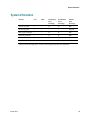
User Management................................................................................................................ 205
Web Interface Help .............................................................................................................. 208
Chapter 8 Customer Support Information
211
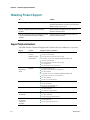
Obtaining Product Support ................................................................................................ 212
4025561 Rev A
v
Contents
Return Product for Repair .................................................................................................. 214
Appendix A Prisma II Permitted CLI Commands
221
From CLI ............................................................................................................................... 222
From ICIM............................................................................................................................. 223
From */* MODULE ............................................................................................................. 229
From TERMINAL ................................................................................................................ 232
Appendix B Features Available via Remote User Interface
233
Overview............................................................................................................................... 234
ICIM Data.............................................................................................................................. 235
Module Data ......................................................................................................................... 238
Current Alarms .................................................................................................................... 239
Module Alarms .................................................................................................................... 240
Module Controls .................................................................................................................. 241
Module Monitors ................................................................................................................. 242
System Information ............................................................................................................. 243
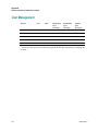
User Management................................................................................................................ 244
Appendix C Module Parameter Descriptions
245
Split and Non-Split Mode for Power Supply and Fan Tray .......................................... 247
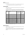
Power Supply and Fan Tray Parameters (Non-Split) ..................................................... 250
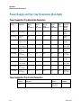
Fan Tray Parameters (Split)................................................................................................ 253
Power Supply 1 Parameters (Split).................................................................................... 255
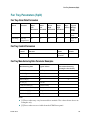
Power Supply 3 Parameters (Split).................................................................................... 257
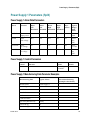
Pre-Amplifier FTTP Parameters ........................................................................................ 259
Post-Amplifier FTTP Parameters....................................................................................... 263
Optical Transmitter FTTP Parameters .............................................................................. 268
Optical Switch FTTP Parameters ....................................................................................... 271
vi
Glossary
275
Index
281
4025561 Rev A
Prisma II Product Notices
Prisma II Product Notices
System Release
The information in this guide pertains to System Release 2.04.01 of the Prisma II
Enhanced Management System platform.
Operating Temperature
CAUTION:
The warranty may be voided and the equipment damaged if you operate the
equipment above the specified temperature limits (131°F/55°C for postamplifiers, 149°F/65°C for other products). Specification temperature limits are
measured in the air stream at the fan tray inlet and may be higher than room
ambient temperature.
CAUTION:
Do not operate post-amplifiers at air inlet temperature above 30°C for
extended periods or repetitively. Extended or repetitive operation above 30°C
will reduce amplifier useful life and increase amplifier failure rate.
Software Terminology
Wherever the term "software" is used in reference to the Prisma II product (in CLI,
ICIM2 front panel, and SOUP Downloader screens, for example), it more accurately
refers to the firmware (or code) that is embedded in the Prisma II product.
4025561 Rev A
vii
Important Safety Instructions
Important Safety Instructions
Read and Retain Instructions
Carefully read all safety and operating instructions before operating this equipment,
and retain them for future reference.
Follow Instructions and Heed Warnings
Follow all operating and use instructions. Pay attention to all warnings and cautions
in the operating instructions, as well as those that are affixed to this equipment.
Terminology
The terms defined below are used in this document. The definitions given are based
on those found in safety standards.
Service Personnel - The term service personnel applies to trained and qualified
individuals who are allowed to install, replace, or service electrical equipment. The
service personnel are expected to use their experience and technical skills to avoid
possible injury to themselves and others due to hazards that exist in service and
restricted access areas.
User and Operator - The terms user and operator apply to persons other than service
personnel.
Ground(ing) and Earth(ing) - The terms ground(ing) and earth(ing) are synonymous.
This document uses ground(ing) for clarity, but it can be interpreted as having the
same meaning as earth(ing).
Electric Shock Hazard
This equipment meets applicable safety standards.
WARNING:
To reduce risk of electric shock, perform only the instructions that are
included in the operating instructions. Refer all servicing to qualified service
personnel only.
Electric shock can cause personal injury or even death. Avoid direct contact with
dangerous voltages at all times. The protective ground connection, where provided,
is essential to safe operation and must be verified before connecting the power
supply.
Know the following safety warnings and guidelines:
Dangerous Voltages
4025561 Rev A
ix
Important Safety Instructions
-
Only qualified service personnel are allowed to perform equipment
installation or replacement.
-
Only qualified service personnel are allowed to remove chassis covers and
access any of the components inside the chassis.
Grounding
-
Prisma II equipment is suitable for installation as part of the common
bonding network (CBN).
-
Do not violate the protective grounding by using an extension cable, power
cable, or autotransformer without a protective ground conductor.
-
Take care to maintain the protective grounding of this equipment during
service or repair and to re-establish the protective grounding before putting
this equipment back into operation.
Installation Site
When selecting the installation site, comply with the following:
Protective Ground - The protective ground lead of the building’s electrical
installation should comply with national and local requirements.
Environmental Condition – The installation site should be dry, clean, and
ventilated. Do not use this equipment where it could be at risk of contact with
water. Ensure that this equipment is operated in an environment that meets the
requirements as stated in this equipment’s technical specifications, which may be
found on this equipment’s data sheet.
Installation Requirements
WARNING:
Allow only qualified service personnel to install this equipment. The
installation must conform to all local codes and regulations.
Equipment Placement
WARNING:
Avoid personal injury and damage to this equipment. An unstable mounting
surface may cause this equipment to fall.
Prisma II equipment is suitable for installation in network telecommunications
facilities.
To protect against equipment damage or injury to personnel, comply with the
following:
Install this equipment in a restricted access location.
x
4025561 Rev A
Important Safety Instructions
Do not install near any heat sources such as radiators, heat registers, stoves, or
other equipment (including amplifiers) that produce heat.
Place this equipment close enough to a DC input voltage source to accommodate
the length of this equipment’s power cord.
Route all power cords so that people cannot walk on, place objects on, or lean
objects against them. This may pinch or damage the power cords. Pay particular
attention to power cords at plugs, outlets, and the points where the power cords
exit this equipment.
Use only with a cart, stand, tripod, bracket, or table specified by the
manufacturer, or sold with this equipment.
Make sure the mounting surface or rack is stable and can support the size and
weight of this equipment.
The mounting surface or rack should be appropriately anchored according to
manufacturer’s specifications. Ensure this equipment is securely fastened to the
mounting surface or rack where necessary to protect against damage due to any
disturbance and subsequent fall.
Ventilation
This equipment has openings for ventilation to protect it from overheating. To
ensure equipment reliability and safe operation, do not block or cover any of the
ventilation openings. Install the equipment in accordance with the manufacturer’s
instructions.
Rack Mounting Safety Precautions
Mechanical Loading
Make sure that the rack is placed on a stable surface. If the rack has stabilizing
devices, install these stabilizing devices before mounting any equipment in the rack.
WARNING:
Avoid personal injury and damage to this equipment. Mounting this
equipment in the rack should be such that a hazardous condition is not caused
due to uneven mechanical loading.
Reduced Airflow
When mounting this equipment in the rack, do not obstruct the cooling airflow
through the rack. Be sure to mount the blanking plates to cover unused rack space.
Additional components such as combiners and net strips should be mounted at the
back of the rack, so that the free airflow is not restricted.
4025561 Rev A
xi
Important Safety Instructions
CAUTION:
Installation of this equipment in a rack should be such that the amount of
airflow required for safe operation of this equipment is not compromised.
Elevated Operating Ambient Temperature
Only install this equipment in a humidity- and temperature-controlled environment
that meets the requirements given in this equipment’s technical specifications.
CAUTION:
If installed in a closed or multi-unit rack assembly, the operating ambient
temperature of the rack environment may be greater than room ambient
temperature. Therefore, install this equipment in an environment compatible
with the manufacturer’s maximum rated ambient temperature.
Handling Precautions
When moving a cart that contains this equipment, check for any of the following
possible hazards:
WARNING:
Avoid personal injury and damage to this equipment! Move any equipment
and cart combination with care. Quick stops, excessive force, and uneven
surfaces may cause this equipment and cart to overturn.
Use caution when moving this equipment/cart combination to avoid injury from
tip-over.
If the cart does not move easily, this condition may indicate obstructions or
cables that may need to be disconnected before moving this equipment to
another location.
Avoid quick stops and starts when moving the cart.
Check for uneven floor surfaces such as cracks or cables and cords.
Grounding
If this equipment is equipped with an external grounding terminal, attach one end of
an 18-gauge wire (or larger) to the grounding terminal; then, attach the other end of
the wire to a ground, such as a grounded equipment rack.
Equipotential Bonding
If this equipment is equipped with an external chassis terminal marked with the IEC
60417-5020 chassis icon ( ), the installer should refer to CENELEC standard EN
50083-1 or IEC standard IEC 60728-11 for correct equipotential bonding connection
instructions.
xii
4025561 Rev A
Important Safety Instructions
Connection to -48 V DC/-60 V DC Power Sources
If this equipment is DC-powered, refer to the specific installation instructions in this
manual or in companion manuals in this series for information on connecting this
equipment to nominal -48 V DC/-60 V DC power sources.
Circuit Overload
Know the effects of circuit overloading before connecting this equipment to the
power supply.
CAUTION:
Consider the connection of this equipment to the supply circuit and the effect
that overloading of circuits might have on overcurrent protection and supply
wiring. Refer to the information on the equipment-rating label when
addressing this concern.
General Servicing Precautions
WARNING:
Avoid electric shock! Opening or removing this equipment’s cover may
expose you to dangerous voltages.
CAUTION:
These servicing precautions are for the guidance of qualified service
personnel only. To reduce the risk of electric shock, do not perform any
servicing other than that contained in the operating instructions unless you
are qualified to do so. Refer all servicing to qualified service personnel.
Be aware of the following general precautions and guidelines:
Servicing - Servicing is required when this equipment has been damaged in any
way, such as power supply cord or plug is damaged, liquid has been spilled or
objects have fallen into this equipment, this equipment has been exposed to rain
or moisture, does not operate normally, or has been dropped.
Wristwatch and Jewelry - For personal safety and to avoid damage of this
equipment during service and repair, do not wear electrically conducting objects
such as a wristwatch or jewelry.
Lightning - Do not work on this equipment, or connect or disconnect cables,
during periods of lightning.
Labels - Do not remove any warning labels. Replace damaged or illegible
warning labels with new ones.
Covers - Do not open the cover of this equipment and attempt service unless
instructed to do so in the instructions. Refer all servicing to qualified service
personnel only.
4025561 Rev A
xiii
Important Safety Instructions
Moisture - Do not allow moisture to enter this equipment.
Cleaning - Use a damp cloth for cleaning.
Safety Checks - After service, assemble this equipment and perform safety
checks to ensure it is safe to use before putting it back into operation.
Electrostatic Discharge
Electrostatic discharge (ESD) results from the static electricity buildup on the human
body and other objects. This static discharge can degrade components and cause
failures.
Take the following precautions against electrostatic discharge:
Use an anti-static bench mat and a wrist strap or ankle strap designed to safely
ground ESD potentials through a resistive element.
Keep components in their anti-static packaging until installed.
Avoid touching electronic components when installing a module.
Fuse Replacement
To replace a fuse, comply with the following:
Disconnect the power before changing fuses.
Identify and clear the condition that caused the original fuse failure.
Always use a fuse of the correct type and rating. The correct type and rating are
indicated on this equipment.
Batteries
This product may contain batteries. Special instructions apply regarding the safe use
and disposal of batteries:
Safety
Insert batteries correctly. There may be a risk of explosion if the batteries are
incorrectly inserted.
Do not attempt to recharge ‘disposable’ or ‘non-reusable’ batteries.
Please follow instructions provided for charging ‘rechargeable’ batteries.
Replace batteries with the same or equivalent type recommended by
manufacturer.
Do not expose batteries to temperatures above 100°C (212°F).
Disposal
xiv
4025561 Rev A
Important Safety Instructions
The batteries may contain substances that could be harmful to the environment
Recycle or dispose of batteries in accordance with the battery manufacturer’s
instructions and local/national disposal and recycling regulations.
The batteries may contain perchlorate, a known hazardous substance, so special
handling and disposal of this product might be necessary. For more information
about perchlorate and best management practices for perchlorate-containing
substance, see www.dtsc.ca.gov/hazardouswaste/perchlorate.
Modifications
This equipment has been designed and tested to comply with applicable safety, laser
safety, and EMC regulations, codes, and standards to ensure safe operation in its
intended environment. Refer to this equipment's data sheet for details about
regulatory compliance approvals.
Do not make modifications to this equipment. Any changes or modifications could
void the user’s authority to operate this equipment.
Modifications have the potential to degrade the level of protection built into this
equipment, putting people and property at risk of injury or damage. Those persons
making any modifications expose themselves to the penalties arising from proven
non-compliance with regulatory requirements and to civil litigation for
compensation in respect of consequential damages or injury.
Accessories
Use only attachments or accessories specified by the manufacturer.
Electromagnetic Compatibility Regulatory Requirements
This equipment meets applicable electromagnetic compatibility (EMC) regulatory
requirements. Refer to this equipment's data sheet for details about regulatory
compliance approvals. EMC performance is dependent upon the use of correctly
shielded cables of good quality for all external connections, except the power source,
when installing this equipment.
Ensure compliance with cable/connector specifications and associated
installation instructions where given elsewhere in this manual.
Otherwise, comply with the following good practices:
Multi-conductor cables should be of single-braided, shielded type and have
conductive connector bodies and backshells with cable clamps that are
conductively bonded to the backshell and capable of making 360° connection to
4025561 Rev A
xv
Important Safety Instructions
the cable shielding. Exceptions from this general rule will be clearly stated in the
connector description for the excepted connector in question.
Ethernet cables should be of single-shielded or double-shielded type.
Coaxial cables should be of the double-braided shielded type.
EMC Compliance Statements
Where this equipment is subject to USA FCC and/or Industry Canada rules, the
following statements apply:
FCC Statement for Class A Equipment
This equipment has been tested and found to comply with the limits for a Class A
digital device, pursuant to Part 15 of the FCC Rules. These limits are designed to
provide reasonable protection against harmful interference when this equipment is
operated in a commercial environment.
This equipment generates, uses, and can radiate radio frequency energy and, if not
installed and used in accordance with the instruction manual, may cause harmful
interference to radio communications. Operation of this equipment in a residential
area is likely to cause harmful interference in which case users will be required to
correct the interference at their own expense.
Industry Canada - Industrie Canadienne Statement
This apparatus complies with Canadian ICES-003.
Cet appareil est confome à la norme NMB-003 du Canada.
CENELEC/CISPR Statement with Respect to Class A Information Technology Equipment
This is a Class A equipment. In a domestic environment this equipment may cause
radio interference in which case the user may be required to take adequate
measures.
xvi
4025561 Rev A
Laser Safety
Laser Safety
Introduction
This equipment contains an infrared laser that transmits intensity-modulated light
and emits invisible radiation.
Warning: Radiation
WARNING:
Avoid personal injury! Use of controls, adjustments, or procedures other
than those specified herein may result in hazardous radiation exposure.
Avoid personal injury! The laser light source on this equipment (if a
transmitter) or the fiber cables connected to this equipment emit invisible
laser radiation. Avoid direct exposure to the laser light source.
Avoid personal injury! Viewing the laser output (if a transmitter) or fiber
cable with optical instruments (such as eye loupes, magnifiers, or
microscopes) may pose an eye hazard.
Do not apply power to this equipment if the fiber is unmated or unterminated.
Do not stare into an unmated fiber or at any mirror-like surface that could reflect
light emitted from an unterminated fiber.
Do not view an activated fiber with optical instruments (e.g., eye loupes,
magnifiers, microscopes).
Use safety-approved optical fiber cable to maintain compliance with applicable
laser safety requirements.
Warning: Fiber Optic Cables
WARNING:
Avoid personal injury! Qualified service personnel may only perform the
procedures in this manual. Wear safety glasses and use extreme caution when
handling fiber optic cables, particularly during splicing or terminating
operations. The thin glass fiber core at the center of the cable is fragile when
exposed by the removal of cladding and buffer material. It easily fragments
into glass splinters. Using tweezers, place splinters immediately in a sealed
waste container and dispose of them safely in accordance with local
regulations.
4025561 Rev A
xvii
Laser Safety
Safe Operation for Software Controlling Optical Transmission Equipment
If this manual discusses software, the software described is used to monitor and/or
control ours and other vendors’ electrical and optical equipment designed to
transmit video, voice, or data signals. Certain safety precautions must be observed
when operating equipment of this nature.
For equipment specific safety requirements, refer to the appropriate section of the
equipment documentation.
For safe operation of this software, refer to the following warnings.
WARNING:
xviii
Ensure that all optical connections are complete or terminated before
using this equipment to remotely control a laser device. An optical or laser
device can pose a hazard to remotely located personnel when operated
without their knowledge.
Allow only personnel trained in laser safety to operate this software.
Otherwise, injuries to personnel may occur.
Restrict access of this software to authorized personnel only.
Install this software in equipment that is located in a restricted access area.
4025561 Rev A
Laser Safety
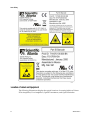
Warning Labels
One or more of the labels shown below are located on Prisma II Pre-Amplifiers, PostAmplifiers, Optical Transmitters, and Optical Switches.
OR
4025561 Rev A
xix
Laser Safety
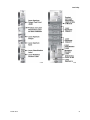
Location of Labels on Equipment
The following illustrations display the typical locations of warning labels on Prisma
II Pre-Amplifiers, Post-Amplifiers, Optical Transmitters, and Optical Switches.
xx
4025561 Rev A
Laser Safety
4025561 Rev A
xxi
Laser Safety
xxii
4025561 Rev A
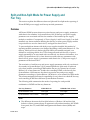
1 Chapter 1
Introduction
Overview
The Prisma II™ Enhanced Management System Intelligent Control
Interface Module 2 (ICIM2) currently supports three methods of
remote user access:
Command Line Interface (CLI)
ICIM Web Interface
Simple Network Management Protocol (SNMP)
This guide describes remote user access for the ICIM2 via CLI and the
ICIM Web Interface. Remote access via SNMP is described in detail in
the Prisma II Enhanced Management System Guide, System Release 2.04,
part number 4025559.
The CLI supports remote monitoring and control of Prisma II
Enhanced platform components and operating parameters by craft
operators and element management systems. The ICIM Web Interface
provides many of the same functions via a user-friendly interface that
requires no knowledge of CLI or other commands.
Purpose
This guide provides complete details on using CLI commands and the
ICIM Web Interface for craft and remote system monitoring and
control.
Who Should Use This Document
This document is intended for authorized service personnel who have
experience working with similar equipment. The service personnel
should have appropriate background and knowledge to complete the
procedures described in this document.
4025561 Rev A
1
Qualified Personnel
Only appropriately qualified and skilled personnel should attempt to
install, operate, maintain, and service this product.
WARNING:
Allow only qualified and skilled personnel to install, operate,
maintain, and service this product. Otherwise, personal injury or
equipment damage may occur.
Scope
This guide discusses the following topics.
Using the Command Line Interface (CLI)
CLI mode commands
Module mode commands
ICIM mode commands
Terminal mode commands
ICIM Web Interface
Descriptions of module parameters
Document Version
This is the first release of this guide (Rev A).
In This Chapter
2
Related Publications ............................................................................... 3
What's New.............................................................................................. 5
4025561 Rev A
Related Publications
Related Publications
You may find the following publications useful as you implement the procedures in
this document.
System Release 2.04
Prisma II Enhanced Management System Guide, System Release 2.04, part number
4025559
Prisma II Enhanced Management System Troubleshooting Guide, System Release 2.04,
part number 4025560
Prisma II Transport System Release 2.04 Release Notes and Installation Instructions,
part number 4027218
System Release 2.01
Prisma II™ Enhanced Management System Guide (for System Release 2.01), part
number 4019220
Prisma II™ Enhanced Management System Troubleshooting Guide (for System
Release 2.01), part number 4019221
Prisma II™ Transport System Release 2.01 Release Notes and Installation Instructions,
part number 4019646
System Release 2.00
Prisma II™ Enhanced Management System Guide (for System Release 2.00), part
number 4015878
Prisma II™ Enhanced Management System Remote User Interface Guide (for System
Release 2.00), part number 4015880
Prisma II™ Enhanced Management System Troubleshooting Guide (for System
Release 2.00), part number 4015879
Prisma II™ Transport System Release 2.00 Release Notes and Installation Instructions,
part number 4017851
System Release 1.01.08
Prisma II™ Enhanced Management System Guide - System Release 1.01, part number
4015429
Prisma II™ Enhanced Management System Command Line Interface (CLI) Reference
Guide - System Release 1.01, part number 4015428
4025561 Rev A
3
Chapter 1 Introduction
Prisma II™ Enhanced Management System Troubleshooting Guide - System Release
1.01, part number 4015396
Prisma II™ Transport System Release Notes, Release 1.01.08, part number 4015881
4
4025561 Rev A
What's New
What's New
This section highlights the major differences between System Release 2.04 and the
earlier System Release 2.01.
Optical Switch Functionality
System Release 2.04 provides new optical switch module firmware that changes the
default nominal input power for Port 3 and Port 4 from 19 dBm to 21 dBm. Despite
this change, the module type (devtype) remains the same as before at 4011.
This change has no effect on the process for monitoring and changing module
parameters through CLI commands or the ICIM Web Interface. Additional details
are provided in info (on page 113), set (on page 127), and show (on page 131).
Optical Transmitter Functionality
System Release 2.04 provides new optical transmitter module firmware that adds
user control of module muting behavior and removes user control of Master-Slave
operation, automatic gain control (AGC), and RF drive level (RFDrive). With these
changes, the module type (devtype) also changes from 1031 to 1033.
This change has no effect on the process for monitoring and changing module
parameters through CLI commands or the ICIM Web Interface. Additional details
are provided in info (on page 113), set (on page 127), and show (on page 131).
4025561 Rev A
5
2 Chapter 2
CLI Overview
Introduction
The command-line interface (CLI) for the Prisma II Intelligent
Communications Interface Module 2 (ICIM2) allows for monitoring
and control of the ICIM2 domain. The ICIM2 domain includes the
ICIM2 itself, the chassis in which it is installed, and all other modules
installed in the chassis and any daisy-chained chassis.
The CLI is designed for use by both local craft operators and remote
monitoring systems. A single command set supports two command
entry formats, one intended for use by human operators and another
designed for efficient communication with network applications.
In This Chapter
4025561 Rev A
Prisma II Enhanced Platform Management Configuration .............. 8
User Authorization ................................................................................. 9
CLI Login and Logout.......................................................................... 10
CLI Command Modes.......................................................................... 12
Command Syntax ................................................................................. 14
General Hints and Help ....................................................................... 18
7
Chapter 2 CLI Overview
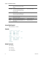
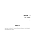
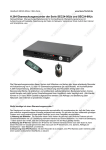
Prisma II Enhanced Platform Management
Configuration
Local or Remote PC
NMS Platform
NMS Application
SA Remote SW
Downloader App
(SOUP)
FTP
Server
ICIM IN/OUT Ports
Daisy Chain
multiple chassis
ICIM2
Optical Module
Optical Module
Power Supply
& Fan Tray
Configuration & Management Bus
Enet
Ethernet
Prisma II Chassis
Local PC
CLI Interface
Hyperterm SW
IP Network
[Username/passwd
Protection – Multiple
Chassis]
Com
Ethernet
TP386
8
4025561 Rev A
User Authorization
User Authorization
Access to the CLI is controlled by password-protected login. Each CLI user is
granted access at one of three authorization levels:
Authorization Level
Description
Admin
Admin level users can add and delete users, change user
passwords, and change IP addresses and other critical values.
Readwrite
Users with Readwrite access can view system parameter values as
well as change most control and operating parameter values.
Read
Users with Read access can view system parameter values, but
cannot change them.
An authorization table in the ICIM2 retains CLI user information. The designated
CLI administrator manages this information by adding, deleting, and changing
authorizations as required.
For further information, see the commands show user (on page 146), user add (on
page 150), user change (on page 152), user delete (on page 154), and user unlock (on
page 155). Additional details are provided in the User Management section of the
Prisma II Enhanced Management System Guide, System Release 2.04, part number
4025559.
4025561 Rev A
9
Chapter 2 CLI Overview
CLI Login and Logout
To use the CLI, you must first establish communication with a chassis in one of two
ways:
Use a serial connection (e.g., HyperTerminal) as described in the Prisma II
Enhanced Management System Guide, System Release 2.04, part number 4025559.
Use your element management system (see your network administrator for
assistance).
Once communication is established, the control console or PC displays the following
message from the ICIM2:
Scientific-Atlanta Intelligent Communications Interface Module (ICIM)
--------------------W A R N I N G
--------------------Unauthorized or improper use of this system may result in
administrative disciplinary action and civil or criminal penalties.
By continuing to use this system you indicate your awareness of and
consent to these terms and conditions of use. LOG OFF IMMEDIATELY
if you do not agree to the conditions stated in this warning.
login:
Note: When communicating via serial connection, some terminal programs may
send unexpected characters to the ICIM2 on initial connection. If this occurs and the
user presses the Enter key to access the login prompt, the ICIM2 may interpret the
unexpected characters as an invalid user name. This leads to a trap and an entry in
the event log indicating a failed login.
To Log In
Complete the following steps to log into the CLI.
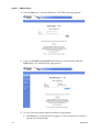
1
At the login prompt, type your assigned user name (or if none is assigned, type
Administrat0r), and then press Enter. The user name is case-sensitive.
2
At the password prompt, type your assigned password (or if none is assigned,
type AdminPassw0rd), and then press Enter. The password is case-sensitive.
An acknowledgement similar to the following appears:
User Admininstrat0r logged in successfully on 09/05/06 at 8:09:18
Previous successful login was on 09/01/06 at 15:56:28
There were no failed attempts to login with this user id previously
CLI>
You can now use CLI commands to interact with the ICIM2.
Note: For security reasons, it is recommended that the default user be changed
immediately. For additional information, see the User Management chapter of the
Prisma II Enhanced Management System Guide, System Release 2.04, part number
4025559.
10
4025561 Rev A
CLI Login and Logout
To Log Out
To log out of the CLI and exit the session, type logout, and then press Enter.
Note: The CLI recognizes the logout command at any command prompt, regardless
of the current command mode.
Important:
For Telnet operation, the computer you are using must have a network
connection through which it can reach the ICIM2 using its IP address.
No more than four Telnet sessions are allowed at one time.
If IPsec is enabled on the ICIM2, it must also be enabled on the remote CLI user's
computer.
CAUTION:
Always use the Logout command to close a serial port or Telnet CLI session.
Closing a serial port session without issuing the Logout command leaves the
session open for a possible future connection. This may allow unauthorized
access by a new user if the previous user had a higher authorization privilege
level.
4025561 Rev A
11
Chapter 2 CLI Overview
CLI Command Modes
All CLI interactions occur in one of four command modes. Command modes affect
the scope of the commands as well as how they are interpreted.
Mode
Description
CLI
The default command mode at login, used for issuing CLI
commands to perform general control and monitoring tasks.
Module
Used to issue Module mode commands, which are directed to a
specific module or range of modules installed in the ICIM2
domain.
ICIM
Used to issue ICIM mode commands, which are directed to the
ICIM2 module itself.
Terminal
Used to issue Terminal mode commands, which control the way
that information is displayed onscreen.
Command Prompts
The onscreen command prompt indicates the command mode currently in effect, as
follows:
Prompt
Meaning
CLI>
CLI mode commands are now recognized.
*/* MODULE>
Module mode commands are now recognized; commands are
directed to all chassis and slots in the ICIM2 domain (see below
for details).
ICIM>
ICIM mode commands are now recognized.
TERMINAL>
Terminal mode commands are now recognized.
Changing Command Modes
CLI mode is the default command mode at login. To select a different command
mode, enter the desired mode name at the CLI> command prompt.
The following sample dialog shows how you could change from CLI mode to
Module mode:
CLI> module
*/* MODULE>
You may then use any CLI commands recognized in Module command mode.
To exit Module mode and return to CLI mode, use the exit command:
*/* MODULE> exit
12
4025561 Rev A
CLI Command Modes
CLI>
If desired, then change to icim command mode as follows:
CLI> icim
ICIM>
You cannot change command modes directly, e.g., by typing terminal at the ICIM>
prompt. Instead, you must first return to CLI mode and then select a new command
mode, as shown below:
ICIM> exit
CLI> terminal
TERMINAL>
4025561 Rev A
13
Chapter 2 CLI Overview
Command Syntax
To facilitate its use by both craft operators and remote monitoring systems, the CLI
accepts commands in either of two formats:
A modal command format allows craft operators to first select a command mode,
and then use mode-specific commands and help screens.
A non-modal command format allows an element management system (or a craft
operator) to enter all command parameters, including command mode changes,
on a single line. While only one command may be entered, the command mode
does not need to be changed between commands.
The syntax for these command formats is described below.
Modal Command Syntax
The general format for a modal CLI command, as a craft operator might send it, is as
follows:
modeName modeOptions
modeOptions
modeOptions Action actionOptions Values
Action actionOptions Values
Exit
The parameters in the command have the following functions:
Keyword
Function
modeName
The name of a mode switch: cli, module, icim, or terminal.
modeOptions
Options that may be associated with the modename.
Action
A command keyword such as set, show, info, etc.
actionOptions
Options that may be associated with the action.
Values
Values that may be associated with the action.
Exit
Used to return to CLI command mode.
Example
Craft operators typically enter commands modally; that is, by first changing to the
appropriate command mode and then entering the desired command.
The following sample dialog illustrates this process.
CLI> module
*/* MODULE> chassis 1 slot 6
01/06 MODULE> alarm module
No active alarms found for the specified module range
14
4025561 Rev A
Command Syntax
01/06 MODULE>
In the first line of this example, the operator selects the Module command mode.
In the next line, the prompt has changed to reflect the new command mode. The
operator then selects chassis 1, slot 6 as the target for subsequent commands.
On pressing Enter, the prompt then changes from */* MODULE> to 01/06
MODULE> to show the selection of chassis 1, slot 6 in effect.
Next, the operator types the alarm module command.
On pressing Enter, the system response "No active alarms found for the specified
module range" reflects the alarm status of the module in chassis 1, slot 6 of the
current ICIM2 domain.
Modal command entry is often helpful for human operators. It can minimize the
need for keystrokes in some cases, thus saving time and eliminating a possible
source of error. Modal operation can also help streamline the work flow by focusing
commands and human attention on a particular chassis or module of interest.
Non-Modal Command Syntax
The general format for a non-modal CLI command, as usually sent from an element
management system, is as follows:
modeName modeOptions Action actionOptions Values Exit
The parameters in the command have the same functions as in modal command
entry:
Keyword
Function
modeName
The name of a mode switch: cli, module, icim, or terminal.
modeOptions
Options that may be associated with the modename.
Action
A command keyword such as set, show, info, etc.
actionOptions
Options that may be associated with the action.
Values
Values that may be associated with the action.
Exit
Used to return to CLI command mode.
Example
A non-modal command is entered without changing command modes. For example,
the alarm module command shown above could have been entered as follows:
CLI> module chassis 1 slot 6 exit
SUCCESS!
CLI> module alarm module exit
No active alarms found for the specified module range
SUCCESS!
CLI>
4025561 Rev A
15
Chapter 2 CLI Overview
The CLI command line interpreter would then parse the command into the
following sequence of instructions:
Switch to Module command mode.
Direct subsequent commands to chassis 1 in the current ICIM2 domain.
Direct subsequent commands to slot 6 of the designated chassis in the current
ICIM2 domain.
Exit Module mode and return to CLI command mode following command
execution.
Display the alarm status of the specified device, i.e., the module occupying
chassis 1, slot 6.
Exit Module mode and return to CLI command mode following command
execution.
This command entry format is generally preferred for use by element management
systems. For maximum efficiency, these systems should be programmed to send CLI
commands in non-modal format, i.e., with all command parameters on a single line.
On occasion, this method may also be more efficient than modal entry for craft
operators who are already very familiar with the syntax of the command being used.
Command Usage Guidelines
CLI commands, unlike login passwords, are insensitive to case. For example, the
keywords Set, set, and SET all have the same meaning in CLI.
If a particular action requires parameters that are not included in the command,
an error message will be issued.
In general, CLI commands issued from an element management system should
have the non-modal "single-line" form shown above. Exceptions may be made
where they will improve efficiency.
For non-modal command entry, the exit parameter is included for backward
compatibility. It is not required in order to return to the CLI mode.
Mode changes can be used to restrict the scope of most CLI commands. When
the command mode changes, the prompt changes to reflect the new mode.
Wildcards
Some CLI command parameters can include one or more "wildcard" characters (*)
for added flexibility.
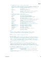
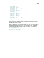
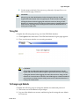
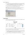
The following sample dialog shows how a craft operator could use a wildcard to
check the output power on all modules in chassis 20:
CLI> module
16
4025561 Rev A
Command Syntax
*/* MODULE> chassis 20 slot *
20/* MODULE> show monitor outpwr
MODID
20/05
20/07
20/13
NAME
OutPwr
OutPwr
OutPwr
VALUE
-5.33429
10.086
-6.15736
UNITS
dBm
dBm
dBm
SUCCESS!
20/* MODULE>
In the first line above, the operator changes from CLI command mode to Module
command mode and specifies chassis 20, any (*) slot.
In the next line, the prompt (20/* MODULE>) has changed to reflect the new
command mode and chassis specification.
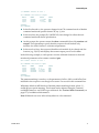
At this prompt, the operator enters the show command followed by monitor and
outpwr. These parameters specify that the response should include only
modules for which OutPwr is a monitored parameter.
In the next four lines, the response identifies each module by its chassis and slot
location (e.g., 20/05) and displays the current output power level in dBm.
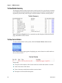
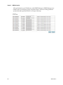
In the following example, a craft operator uses the wildcard character to check all
monitored parameters whose name contained pwr:
CLI> module chassis 20 slot *
20/* MODULE> show monitor *pwr*
MODID
20/05
20/07
20/14
20/14
NAME
OutPwr
OutPwr
OutPwrA
OutPwrB
VALUE
8.3
5.91542
18.9057
18.8904
UNITS
dBm
dBm
dBm
dBm
SUCCESS!
20/* MODULE>
The pattern matching is caseless, so the parameters OutPwr, InPwr, and InPwr2 are
included in the response even though a lowercase P was used in the command line.
Wildcards default to MS Windows filename pattern matching format, where ?, *,
and [x-y] have special meaning. This format can be adjusted using the Terminal
command Pattern to use POSIX regex wildcards. See Terminal Mode Commands (on
page 157) for additional information.
Note: Wildcards are never allowed anywhere in a Set command.
4025561 Rev A
17
Chapter 2 CLI Overview
General Hints and Help
The CLI command information in this section applies regardless of the command or
command mode currently in use.
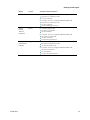
Shortcuts and Abbreviations
The CLI interpreter recognizes shortcuts and abbreviations for certain commands. A
shortcut is a single key or key combination (such as Ctrl-u) that is functionally
equivalent to a longer command. Shortcuts are handy for craft operators because
they reduce keystrokes, saving time and reducing the risk of a typing error.
The following table lists the shortcuts available in all CLI command modes.
18
Shortcut
Description
TAB
Automatically completes typing of a keyword.
?
Displays a list of expected keywords or tokens.
Ctrl-d
Deletes the current character.
Ctrl-u
Deletes text up to the cursor.
Ctrl-k
Deletes text from the cursor to the end of the line.
Ctrl-a
Moves the cursor to the beginning of the line.
Ctrl-e
Moves the cursor to the end of the line.
Ctrl-p
Gets the previous command from history.
Ctrl-n
Gets the next command from history.
Ctrl-b
Moves the cursor left.
Ctrl-f
Moves the cursor right.
Esc-b
Moves back one word.
Esc-f
Moves forward one word.
Esc-c
Converts the remainder of the word to uppercase.
Esc-l
Converts the remainder of the word to lowercase.
Esc-d
Deletes the remainder of the word.
Ctrl-w
Deletes the current word up to the cursor.
Ctrl-t
Transposes the current and previous characters.
Ctrl-z
Enters the command and then returns to the root prompt.
Ctrl-l
Refreshes the input line.
↑
Gets the previous command from history.
↓
Gets the next command from history.
4025561 Rev A
General Hints and Help
Shortcut
Description
←
Moves the cursor left.
→
Moves the cursor right.
Note: This list can also be viewed in CLI by issuing the command help edit.
An abbreviation is a truncated form of a command name. The CLI recognizes the
shortest character string that uniquely identifies a command or parameter. For
example, in CLI command mode, typing i (or ici, etc.) is recognized as equivalent to
typing the icim command. As with shortcuts, abbreviations are useful for craft
operators because they save typing time and reduce the chance of typing error.
Note: Shortcuts and abbreviations should not be used in commands sent by network
or element management systems. In an NMS or EMS context, they do not
significantly reduce typing time or error, and may make program code more
difficult to maintain.
Alarm Information
You can use the alarm command in any command mode to get a list of currently
active alarms in the ICIM2 domain. In Module command mode, you can use the
alarm module command to narrow the scope of the response. For details, see alarm
module (on page 46).
Getting Online Help
To display a listing of recognized commands for the current command mode, type
help and then press Enter, or simply type the ? character.
Typing the ? character is the best way to get help for available commands and
parameters. For example:
Typing ? at the ICIM> prompt will show all of the available ICIM mode
commands.
Typing set ? at the ICIM> prompt will show all of the available parameters for
the set command.
To display a description of all recognized commands for the current command
mode, type manual and then press Enter.
You can also display a list of recognized commands for Module, ICIM, and Terminal
modes from CLI command mode using the following commands:
module manual
terminal manual
icim manual
4025561 Rev A
19
Chapter 2 CLI Overview
Note: A summary of recognized CLI commands by command mode is provided in
Prisma II Permitted CLI Commands (on page 221).
20
4025561 Rev A
3 Chapter 3
CLI Mode Commands
Introduction
This chapter describes the commands that can be executed in CLI
command mode. Some of the commands available in CLI command
mode are global in scope, and give the same results whether entered in
CLI mode or another command mode.
In This Chapter
4025561 Rev A
alarm ....................................................................................................... 22
clear......................................................................................................... 23
date.......................................................................................................... 24
help ......................................................................................................... 25
icim.......................................................................................................... 27
logout...................................................................................................... 28
manual.................................................................................................... 30
module.................................................................................................... 32
terminal .................................................................................................. 33
who ......................................................................................................... 34
whoami................................................................................................... 35
21
Chapter 3 CLI Mode Commands
alarm
Syntax
alarm
Description
The alarm command is used to display all active alarms in the domain of the ICIM2.
This command produces the same results whether entered in CLI, Module,
Terminal, or ICIM command mode.
Note: This command is functionally equivalent to alarm domain (on page 45).
Parameters
None
Access Rights Required
Read, ReadWrite, or Admin
Example
CLI> alarm
No active alarms found
SUCCESS!
CLI>
This response shows that no alarms are active in the ICIM2 domain. To narrow the
command scope to specific chassis or modules, use alarm module (on page 46).
Related Commands
alarm (Module command mode)
alarm (ICIM command mode)
alarm (Terminal command mode)
alarm domain (Module command mode)
alarm module (Module command mode)
22
4025561 Rev A
clear
clear
Syntax
clear
Description
The clear command is used to clear the terminal display.
Parameters
None
Access Rights Required
Read, ReadWrite, or Admin
Example
CLI> clear
[screen clears and new prompt appears at top line]
CLI>
Related Commands
None
4025561 Rev A
23
Chapter 3 CLI Mode Commands
date
Syntax
date
Description
The date command is used to display the current date and time.
Parameters
None
Access Rights Required
Read, ReadWrite, or Admin
Example
CLI> date
Tue, 3 Oct 2006 11:36:43 EST
SUCCESS!
CLI>
Related Commands
show clock (ICIM command mode)
24
4025561 Rev A
help
help
Syntax
help modeOption
Description
The help command is used alone to display onscreen help for all CLI mode
commands, or with a modeOption parameter to display help for a single command
or function.
Note: Typing a question mark (?) character at the CLI> command prompt gives the
same result as typing help without a mode option parameter.
Parameters
The possible values for the modeOption parameter and their results are listed
below.
modeOption
Description
<empty>
Displays onscreen help for all recognized CLI mode commands.
<commandname>
Displays onscreen help for the specified command, if recognized.
edit
Displays onscreen help for command line editing and syntax.
commands
Displays onscreen help for global commands (exit, help, who,
whoami).
Access Rights Required
Read, ReadWrite, or Admin
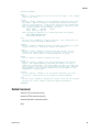
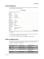
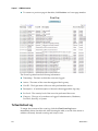
Examples
CLI> help
alarm
clear
date
icim
logout
manual
module
terminal
-
Display active alarms for all modules
Clear the screen
Display the current system date & time
Enter ICIM mode
Log off this system
Show detailed help text
Enter module mode
Enter terminal mode
CLI> help edit
Available editing keystrokes
4025561 Rev A
25
Chapter 3 CLI Mode Commands
Delete current character.....................Ctrl-d
Delete text up to cursor.....................Ctrl-u
Delete from cursor to end of line............Ctrl-k
Move to beginning of line....................Ctrl-a
Move to end of line..........................Ctrl-e
Get prior command from history...............Ctrl-p
Get next command from history................Ctrl-n
Move cursor left.............................Ctrl-b
Move cursor right............................Ctrl-f
Move back one word...........................Esc-b
Move forward one word........................Esc-f
Convert rest of word to uppercase............Esc-c
Convert rest of word to lowercase............Esc-l
Delete remainder of word.....................Esc-d
Delete word up to cursor.....................Ctrl-w
Transpose current and previous character.....Ctrl-t
Enter command and return to root prompt......Ctrl-z
Refresh input line...........................Ctrl-l
CLI>
Related Commands
help (Module command mode)
help (ICIM command mode)
help (Terminal command mode)
26
4025561 Rev A
icim
icim
Syntax
icim
Description
The icim command is used to change from CLI command mode to ICIM command
mode.
Parameters
None
Access Rights Required
Read, ReadWrite, or Admin
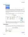
Examples
CLI is the default command mode at login. To enter ICIM command mode, enter the
icim command as follows:
CLI> icim
ICIM> exit
CLI>
To enter ICIM command mode from any command mode other than CLI, it is
necessary to first exit to CLI command mode, as follows:
*/* MODULE> exit
CLI> ICIM
ICIM>
Related Commands
module
terminal
exit
4025561 Rev A
27
Chapter 3 CLI Mode Commands
logout
Syntax
logout
Description
The logout command is used to terminate the current CLI session. This command is
available in every command mode.
Important:
For Telnet operation, the computer you are using must have a network
connection through which it can reach the ICIM2 using its IP address.
No more than four Telnet sessions are allowed at one time.
If IPsec is enabled on the ICIM2, it must also be enabled on the remote CLI user's
computer.
CAUTION:
Always use the Logout command to close a serial port or Telnet CLI session.
Closing a serial port session without issuing the Logout command leaves the
session open for a possible future connection. This may allow unauthorized
access by a new user if the previous user had a higher authorization privilege
level.
Parameters
None
Access Rights Required
Read, ReadWrite, or Admin
Example
CLI> logout
connection to host lost
C:\>
Related Commands
logout (Module command mode)
logout (ICIM command mode)
28
4025561 Rev A
logout
logout (Terminal command mode)
4025561 Rev A
29
Chapter 3 CLI Mode Commands
manual
Syntax
modeOption manual
Description
The manual command is used to display detailed help for CLI command mode, or
for another command mode if specified by a preceding modeOption parameter.
Parameters
The possible values for the modeOption parameter and their results are listed
below.
modeOption
Description
<empty>
Displays detailed help for CLI command mode.
module
Displays detailed help for Module command mode.
terminal
Displays general help for Terminal command mode.
icim
Displays detailed help for ICIM command mode.
Access Rights Required
Read, ReadWrite, or Admin
Example
CLI> manual
Try one of these help commands for details on specific modes:
module manual
terminal manual
icim manual
General Hints:
Keywords can be abbreviated to a unique prefix. For instance
in CLI mode, the keyword 'MODULE' can be given as just 'm'
or 'mod'.
Use
Use
Use
Use
TAB to autocomplete a keyword.
? to list expected keywords or tokens (depends on previous input).
BACKSPACE to erase previous characters.
'help edit' to display more editing commands
Use Alarm in any mode to get a list of active alarms. When in Module
mode, you can also narrow the list of active alarms to just those in
the current ModSpec range. See the Module Help for further details.
Note: entering a mode command (MODULE, ICIM, TERMINAL) enters that mode
immediately but it is not indicated until the next prompt is displayed.
30
4025561 Rev A
manual
The interface uses modes: CLI, MODULE, TERMINAL, and ICIM. The prompt
reflects the current mode. Enter the mode name to enter that mode, and
use EXIT to leave the mode and return to CLI mode.
CLI>
Related Commands
manual (ICIM command mode)
manual (Module command mode)
manual (Terminal command mode)
help
4025561 Rev A
31
Chapter 3 CLI Mode Commands
module
Syntax
module
Description
The module command is used to change from CLI command mode to Module
command mode.
Parameters
None
Access Rights Required
Read, ReadWrite, or Admin
Examples
CLI is the default command mode at login. To enter Module command mode, enter
the module command as follows:
CLI> module
*/* MODULE> exit
CLI>
To enter Module command mode from any command mode other than CLI, it is
necessary to first exit to CLI command mode, as follows:
ICIM> exit
CLI> module
*/* MODULE>
Related Commands
icim
terminal
exit
32
4025561 Rev A
terminal
terminal
Syntax
terminal
Description
The terminal command is used to change from CLI command mode to Terminal
command mode.
Parameters
None
Access Rights Required
Read, ReadWrite, or Admin
Examples
CLI is the default command mode at login. To enter Terminal command mode, enter
the terminal command as follows:
CLI> terminal
TERMINAL> exit
CLI>
To enter Terminal command mode from any command mode other than CLI, it is
necessary to first exit to CLI command mode, as follows:
*/* MODULE> exit
CLI> terminal
TERMINAL>
Related Commands
module
icim
exit
4025561 Rev A
33
Chapter 3 CLI Mode Commands
who
Syntax
who
Description
The who command is used to display a list of the currently logged in users.
Parameters
None
Access Rights Required
Admin
Example
CLI> who
LOGIN IDENTIFIER
Administrat0r
IP ADDRESS
local console
TYPE
CLI
LOGIN TIME
03/13/07 11:22:01
SUCCESS!
CLI>
Note: The value in the IP Address column indicates the IP address from which the
remote user is connecting to the ICIM2. If the user is connecting locally via the
ICIM2 front-panel serial port, the value in this column will be "local console," as
shown in the example above.
Related Commands
whoami
34
4025561 Rev A
whoami
whoami
Syntax
whoami
Description
The whoami command is used to display the username of the current CLI user.
Parameters
None
Access Rights Required
Read, ReadWrite, or Admin
Example
CLI> whoami
User name: Administrat0r
CLI>
Related Commands
who
4025561 Rev A
35
4 Chapter 4
Module Mode Commands
Introduction
This chapter describes the CLI commands that can be executed in the
Module command mode.
4025561 Rev A
37
Chapter 4 Module Mode Commands
In This Chapter
38
Overview................................................................................................ 39
About Modspecs ................................................................................... 41
alarm ....................................................................................................... 44
alarm domain ........................................................................................ 45
alarm module ........................................................................................ 46
chassis..................................................................................................... 47
exit........................................................................................................... 49
help ......................................................................................................... 50
info alarm ............................................................................................... 52
info control............................................................................................. 54
info module............................................................................................ 56
info monitor ........................................................................................... 58
logout...................................................................................................... 60
manual.................................................................................................... 61
modid ..................................................................................................... 65
reset......................................................................................................... 67
set alarmparam...................................................................................... 69
set control............................................................................................... 74
set module.............................................................................................. 78
show alarmparam ................................................................................. 80
show alarmstate .................................................................................... 84
show control .......................................................................................... 88
show module ......................................................................................... 91
show monitor ........................................................................................ 92
slot........................................................................................................... 96
4025561 Rev A
Overview
Overview
Module mode commands allow for the control and monitoring of a selected module
or range of modules. The scope of a Module mode command is defined using a
special command called a module specification, or modspec. The Module mode
command prompt always indicates the modspec currently in effect. For additional
information, see About Modspecs (on page 41).
Types of Module Commands
The following commands are recognized in Module command mode:
The alarm commands are used to display active alarms in selected portions of
the ICIM2 domain.
The chassis command is used to select a chassis or range of chassis for
subsequent commands.
The exit command is used to exit Module command mode and return to CLI
command mode.
The help command is used to display abbreviated help for Module mode
commands.
The info commands are used to display selected alarm, control, module, or
monitoring information in detail.
The logout command is used to exit CLI and return to the system prompt.
The manual command is used to display detailed help for Module mode
commands.
The modid command is used to specify the modspec (chassis and slot) for
subsequent commands.
The reset command is used to restore module controls and alarms to their
factory default values.
The set commands are used to assign a value to alarm or control parameters.
The show commands are used to display the values of selected alarm, control,
module, or monitoring parameters.
The slot command is used to select a slot or range of slots for subsequent
commands.
This chapter describes these commands and their applications in detail.
Note: The show commands can accept a wildcard character as well as a range of
chassis and slots. All other Module mode commands must be applied to a specific
chassis and slot location, as explained in About Modspecs (on page 41).
4025561 Rev A
39
Chapter 4 Module Mode Commands
To Access Module Command Mode
The CLI only recognizes Module mode commands in Module command mode.
Complete the following steps to enter Module command mode.
40
1
Confirm that you have logged onto CLI as explained in CLI Login and Logout
(on page 10).
2
At the CLI> prompt, type Module, and then press Enter.
3
Confirm that the command prompt changes to X/Y MODULE> where X and Y
are either *, a number, or a range of numbers in brackets. You are now in Module
command mode.
4025561 Rev A
About Modspecs
About Modspecs
Module specifications, or modspecs, are commands that specify a module or range
of modules as targets for subsequent Module mode commands. The Module mode
command prompt always reflects the modspec currently in effect. For this reason,
the term modspec also loosely refers to the Module mode prompt itself.
Module Command Prompt
Once in Module mode, the command prompt takes the form
X/Y MODULE>
where X indicates the chassis specification currently in effect, and Y indicates the
current slot specification.
The appearance of the Module command prompt changes to reflect the changing
modspec, as shown in the following examples.
Module Prompt
Indication
*/* MODULE>
The modspec is "wild." The command will include all slots
and chassis in the ICIM2 domain.
20/* MODULE>
The modspec specifies a chassis but not a slot. The command
will address all slots (modules) in chassis 20.
*/11 MODULE>
The modspec specifies a slot but not a chassis. The command
will address slot 11 of all chassis in the ICIM2 domain.
20/11 MODULE>
The modspec specifies a chassis and a slot. The command will
address only slot 11 of chassis 20 in the ICIM2 domain.
[1-7]/[4-15] MODULE>
The modspec indicates a range of slots and chassis. The
command will address slots 4-15 of chassis 1-7 in the domain.
Modspec Commands
Three commands, chassis, slot, and modid, allow you to select a single chassis and
slot location, a range of chassis or slots (or some combination), or the entire ICIM2
domain.
chassis
The chassis command can be used to specify any of the following:
A single chassis, using the chassis ID number (0-99).
A range of chassis, using two chassis ID numbers in brackets, e.g., [2-87].
All chassis in the ICIM2 domain, using the wildcard character (*) in place of a
chassis ID.
4025561 Rev A
41
Chapter 4 Module Mode Commands
The following sample dialog illustrates the use of all three methods. Note how the
Module mode prompt changes on each line to reflect the changing modspec.
*/* MODULE> chassis 10
(selects any slot in chassis 10)
10/* MODULE> chassis [2-87]
(selects any slots in chassis 2-87)
[02-87]/* MODULE> chassis *
(selects all chassis and slots)
*/* MODULE>
slot
The slot command can be used to specify any of the following:
A single slot, using the slot number (0-47).
A range of slots, using two slot numbers in brackets, e.g., [2-18].
All slots in all chassis currently specified, using the wildcard character (*) in
place of a slot number.
The following sample dialog illustrates the use of all three methods. Note how the
Module prompt changes on each line to reflect the changing modspec.
10/* MODULE> slot [2-18]
(selects chassis 10, slots 2-18)
10/[02-18] MODULE> slot 15
(selects chassis 10, slot 15)
10/15 MODULE> slot *
(selects chassis 10, all slots)
10/* MODULE>
chassis and slot
The chassis and slot commands can also be used together on a single command line,
as shown in the following example.
10/* MODULE> chassis [1-5] slot [4-13]
(selects chassis 1-5, slots 4-13)
[01-05]/[04-13] MODULE> chassis 5 slot 12 (selects chassis 5, slot 12)
05/12 MODULE> chassis * slot *
(selects all chassis and slots)
*/* MODULE>
modid
The modid command combines the functions of the chassis and slot commands,
allowing you to specify a chassis and slot location using a single parameter, as
shown below.
*/* MODULE> modid [1-5]/[4-13]
(selects chassis 1-5, slots 4-13)
[01-05]/[04-13] MODULE> modid 0512
(selects chassis 5, slot 12)
05/12 MODULE> modid *
(selects all chassis and slots)
*/* MODULE>
The modid command can be somewhat faster to enter, but the resulting dialog may
be less readable than when using the chassis and slot commands, either separately
or together on one command line.
42
4025561 Rev A
About Modspecs
Notes on Usage
Modspecs stay in effect when exiting and re-entering Module command mode.
However, modspecs do not affect the scope of CLI, ICIM, or Terminal mode
commands.
When specifying a range of chassis or slots, the specified range need not be fully
populated. For example, the chassis range [1-7] is valid even if there are fewer
than seven chassis within that range. In addition, all chassis within the specified
range are included whether or not their chassis numbers are contiguous.
For an element management system or other automatic control interface, a
specific chassis and slot are required for backward compatibility, and should
always be specified.
For craft operators, ranges may be specified for all Module mode commands
except for set.
4025561 Rev A
43
Chapter 4 Module Mode Commands
alarm
Syntax
alarm
Description
The alarm command is used to display all active alarms in the domain of the ICIM2.
This command produces the same results whether entered in CLI, Module,
Terminal, or ICIM command mode.
Note: This command is functionally equivalent to alarm domain (on page 45).
Parameters
None
Access Rights Required
Read, ReadWrite, or Admin
Example
20/* MODULE> alarm
No active alarms found
SUCCESS!
20/* MODULE>
This response shows that no alarms are active in the ICIM2 domain. To narrow the
command scope to specific chassis or modules, use alarm module (on page 46).
Related Commands
alarm (CLI command mode)
alarm (ICIM command mode)
alarm (Terminal command mode)
alarm domain
alarm module
44
4025561 Rev A
alarm domain
alarm domain
Syntax
alarm domain
Description
The alarm domain command is used to display all active alarms in the domain of the
ICIM2.
Note: This command is functionally equivalent to the alarm command.
Parameters
None
Access Rights Required
Read, ReadWrite, or Admin
Example
20/* MODULE> alarm domain
No active alarms found
SUCCESS!
20/* MODULE>
This response indicates that no alarms are currently active anywhere in the ICIM2
domain. The scope of the response is not limited to chassis 20, despite the current
status of the Module prompt.
Related Commands
alarm
alarm module
4025561 Rev A
45
Chapter 4 Module Mode Commands
alarm module
Syntax
alarm module
Description
The alarm module command is used to display all active alarms in the range
indicated by the Module prompt (modspec).
Parameters
None
Access Rights Required
Read, ReadWrite, or Admin
Example
20/[5-7] MODULE> alarm module
No active alarms found for the specified module range
SUCCESS!
20/[5-7] MODULE>
This response indicates that no alarms are currently active in modules 5, 6, or 7 of
chassis 20 in the ICIM2 domain. It does not reflect any alarms that may exist in other
modules in chassis 20 or in other chassis in the domain.
Related Commands
alarm
alarm domain
46
4025561 Rev A
chassis
chassis
Syntax
chassis chassisidvalue
Description
The chassis command is used to specify:
A single chassis, using the chassis ID number (0-99).
A range of chassis, using two chassis ID numbers in brackets, e.g., [2-87].
All chassis in the ICIM2 domain, using the wildcard character (*) in place of a
chassis ID.
Parameters
The chassisidvalue parameter can be any number from 0 to 99, a bracketed pair of
numbers in the same range separated by a hyphen (-), or a wildcard (*) to indicate all
chassis.
Access Rights Required
Read, ReadWrite, or Admin
Example
The following sample dialog illustrates the use of all three methods described above.
*/* MODULE> chassis 10
(selects any slot in chassis 10)
10/* MODULE> chassis [2-87]
(selects chassis 2-87, all slots)
[02-87]/* MODULE> chassis *
(selects all chassis and slots)
*/* MODULE>
Notes on Usage
The chassis command can be used together with the slot command to specify a
particular chassis and slot location. However, it is often simpler to use the modid
command for this purpose. See modid (on page 65) for details.
Modspecs stay in effect when exiting and re-entering Module command mode.
However, modspecs do not affect the scope of CLI, ICIM, or Terminal mode
commands.
When specifying a range of chassis or slots, the specified range need not be fully
4025561 Rev A
47
Chapter 4 Module Mode Commands
populated. For example, the chassis range [1-7] is valid even if there are fewer
than seven chassis within that range. In addition, all chassis within the specified
range are included whether or not their chassis numbers are contiguous.
For an element management system or other automatic control interface, a
specific chassis and slot are required for backward compatibility, and should
always be specified.
For craft operators, ranges may be specified for all Module mode commands
except for set.
Related Commands
slot
modid
48
4025561 Rev A
exit
exit
Syntax
exit
Description
The exit command is used to exit Module command mode to the CLI command
mode for the purpose of entering CLI mode commands or selecting ICIM or
Terminal command mode.
Note: The exit command is not recognized in CLI mode and does not result in a
logout. See logout (on page 60) for details.
Parameters
None
Access Rights Required
Read, ReadWrite, or Admin
Example
*/* MODULE> exit
CLI> icim
ICIM> exit
CLI> terminal
TERMINAL> exit
CLI> module
*/* MODULE>
Related Commands
logout
4025561 Rev A
49
Chapter 4 Module Mode Commands
help
Syntax
help modeOption
Description
The help command is used alone to display onscreen help for all Module mode
commands, or with a modeOption parameter to display help for a single command
or function.
Note: Typing a question mark (?) at the command prompt gives the same result as
typing help without a mode option parameter.
Parameters
The possible values for the modeOption parameter and their results are listed
below.
modeOption
Description
<empty>
Displays onscreen help for all recognized Module mode
commands.
<commandname>
Displays onscreen help for the specified command, if recognized.
edit
Displays onscreen help for command line editing and syntax.
commands
Displays onscreen help for global commands (exit, help, who,
whoami).
Access Rights Required
Read, ReadWrite, or Admin
Example
*/* MODULE> help
50
4025561 Rev A
help
module
alarm
chassis
info
logout
manual
modid
reset
set
show
slot
- Enter module mode
- Display active alarms
- Set the chassis (and optionally the slot) specification
for module commands
- Display detailed information regarding modules
- Log off this system
- Show detailed help text
- Set the chassis and slot ranges for module commands
- Reset a module to its default values
- Set a value for a module
- Display the values of specified parameters. If the alarm
param parameter is specified then the name and alarm_par
am parameters must also be specified. If the alarmstate,
control or monitor parameters are specified, then the
name (and only name) parameter must also be specified.
If the module parameter is specified, then no other
parameters are accepted.
- Set the slot specification for module commands
*/* MODULE>
Related Commands
help (CLI command mode)
help (ICIM command mode)
help (Terminal command mode)
4025561 Rev A
51
Chapter 4 Module Mode Commands
info alarm
Syntax
info alarm alarmName detail1 detail2 . . . detailn
Description
The info alarm command is used to display more detailed alarm information than is
returned by using the show command.
Parameters
The alarmName parameter specifies the type of alarm. The allowable alarmName
values vary by module because different modules have different types of alarms. To
learn about possible alarms for each module, do one of the following:
Use the modid command to select a single module (by chassis and slot location),
and then issue the command alarmstate * to list all available alarm names.
When entering this command, do not use the letter h to abbreviate hysteresis, as
this will instead invoke the help command.
See Module Parameter Descriptions (on page 245) for a list of possible alarms for
each module.
The detail parameters specify the characteristics that can be requested for each
alarmName, as follows:
52
Detail parameter
Description
Hysteresis
Threshold hysteresis value.
Index
Alarm number, starting at 1, in the list of alarms.
Label
Name of the alarm.
Limitadjust
Allowed if alarm is adjustable, not allowed if not.
Majorhigh
High Major threshold.
Majorlow
Low Major threshold.
Minorhigh
High Minor threshold.
Minorlow
Low Minor threshold.
Nominal
Alarm nominal value.
Rangehi
Upper limit for this threshold.
Rangelo
Lower limit for this threshold.
4025561 Rev A
info alarm
Detail parameter
Description
Type
Alarm type (types 1, 2, and 7 are adjustable).
Value
Alarm state.
Access Rights Required
Read, ReadWrite, or Admin
Example
The following sample dialog illustrates the use of the info alarm command to view
the thresholds of a post-amplifier output power alarm. Note that these thresholds
are relative to the nominal alarm value.
02/05 MODULE> info alarm outpwra majorhigh minorhigh minorlow majorlow
hysteresis nominal
MODID NAME
MAJORHIGH MINORHIGH MINORLOW MAJORLOW HYSTERESIS NOMINAL
02/05 OutPwrA 1
0.7
-0.7
-1
0.1
17.7
SUCCESS!
02/05 MODULE>
Related Commands
info control
info module
info monitor
show alarmstate
show alarmparam
4025561 Rev A
53
Chapter 4 Module Mode Commands
info control
Syntax
info control controlName detail1 detail2 . . . detailn
Description
The info control command is used to display more detailed control information than
is returned by using the show command.
Parameters
The controlName parameter specifies the type of control. Different application
modules have different types of controls, so the allowable controlName values vary
by module type. For a listing of controlName values for a particular module, use the
modid command to select a single chassis and slot, and then issue the command
show control * to list all available control names.
The detail parameters specify the characteristics that can be requested for the
controlName, and are as follows:
Detail parameter
Description
Index
Control number, starting at 1, in the list of controls.
Label
Name of the control.
Rangehi
Upper limit for this control.
Rangelo
Lower limit for this control.
Rangestep
Smallest increment allowed.
Statenames
List of symbolic control values.
Type
Control type: D(igital), F(loat), B(oolean), S(tate).
Units
Control unit.
Value
Control setting.
Access Rights Required
Read, ReadWrite, or Admin
Example
The following sample dialog illustrates the use of the info control command to view
the value and statenames characteristics for the mode control:
54
4025561 Rev A
info control
20/08 MODULE> info control mode value statenames
MODID
20/08
NAME
Mode
VALUE
Auto (2)
STATENAMES
Cross (0), Bar (1), Auto (2)
SUCCESS!
20/08 MODULE>
In the example above, the control's name pattern was explicit (no wildcards). The
details to be listed were Value and the available StateNames (not all controls and
monitors have StateNames). In this case, the value is Auto (2).
Related Commands
info alarm
info module
info monitor
show control
4025561 Rev A
55
Chapter 4 Module Mode Commands
info module
Syntax
info module detail1 detail2 . . . detailn
Description
The info module command is used to display more detailed module information
than is returned by using the show command.
Parameters
The detail parameter specifies the characteristics that can be requested for each
module in the command scope, and are as follows:
56
Detail parameter
Description
Activerev
Active software image revision for the module.
Bootrev
Current boot image revision for the module.
CLEI
Common Language Equipment Identification code for module.
CLLI
Common Language Location Identification code for module.
Coderev
Indicates module vintage.
Datecode
Manufacturing date (encoded).
Devtype
Numeric type value used for element manager.
Downldable
Module can be downloaded with new firmware.
Inactiverev
Inactive software image revision for the module.
Mandata
Manufacturing data.
Modtype
Manufacturing data (alias for MANDATA).
Name
Name of module.
Nextimage
Image that will be active after the next reboot.
Numanalogcontrols
Number of analog controls.
Numcontrols
Total number of controls.
Numdigitalcontrols
Number of digital controls.
Nummonits
Number of monitored values.
Numofalarms
Number of alarms.
Scriptrev
Script revisions.
4025561 Rev A
info module
Detail parameter
Description
Selftest
Status of module self test.
Serial
Serial number.
Tos
Time of service.
Access Rights Required
Read, ReadWrite, or Admin
Example
The example below shows how a network management system might construct an
info module command to determine the domain of an ICIM2.
CLI> module chassis * slot *
CLI> module info module devtype name exit
MODID
20/00
20/03
20/05
20/06
20/07
20/08
20/09
20/13
20/14
|
|
|
|
|
|
|
|
|
|
DEVTYPE
5012
5013
1001
2002
1001
4000
3011
3000
2000
|
|
|
|
|
|
|
|
|
|
NAME
Fan Tray
Power Supply 3
1310nm Forward Transmit
Forward Receiver
1310nm Forward Transmit
Optical Switch
FHEDA
1550nm Optical Amplifier
Reverse Data Receiver
SUCCESS!
CLI> logout
Related Commands
info alarm
info control
info monitor
show module
4025561 Rev A
57
Chapter 4 Module Mode Commands
info monitor
Syntax
info monitor monitorname detail1 detail2 . . . detailn
Description
The info monitor command is used to display more detailed monitor information
than is returned by using the show command.
Parameters
The monitorname parameter specifies the type of monitored information. Because
different applications modules have different types of monitored parameters, the
allowable monitorname values vary by module type. For a listing of monitorname
values for a particular module, use the modid command to select a single chassis
and slot, and then issue the command show monitor * to list all available monitor
names.
The detail parameters specify the characteristics that can be requested for each
monitorname, and are as follows:
Monitor Name
Description
Index
Monitor number, starting at 1, in the list of monitors.
Label
Name of monitor.
Statenames
List of symbolic values.
Type
Value type: D(igital), F(loat), B(oolean), S(tate).
Units
Units of measurement.
Value
Value of monitor.
Access Rights Required
Read, ReadWrite, or Admin
Example
The following sample dialog illustrates the use of this command:
01/05 MODULE> info monitor inrf index label statenames type units value
MODID
01/05
58
NAME
InRF
INDEX
1
LABEL
InRF
STATENAMES
N/A
TYPE
F
UNITS
dB
VALUE
0.511787
4025561 Rev A
info monitor
SUCCESS!
01/05 MODULE>
In the example above, the monitor's name pattern was explicit (no wildcards). The
details to be listed were all possible monitor details for a Transmitter Input RF
monitor name.
Related Commands
info alarm
info control
info module
4025561 Rev A
59
Chapter 4 Module Mode Commands
logout
Syntax
logout
Description
The logout command is used to terminate the current CLI session. This command is
available in every command mode.
Important:
For Telnet operation, the computer you are using must have a network
connection through which it can reach the ICIM2 using its IP address.
No more than four Telnet sessions are allowed at one time.
If IPsec is enabled on the ICIM2, it must also be enabled on the remote CLI user's
computer.
CAUTION:
Always use the Logout command to close a serial port or Telnet CLI session.
Closing a serial port session without issuing the Logout command leaves the
session open for a possible future connection. This may allow unauthorized
access by a new user if the previous user had a higher authorization privilege
level.
Parameters
None
Access Rights Required
Read, ReadWrite, or Admin
Example
*/* MODULE> logout
connection to host lost
C:\>
Related Commands
exit
60
4025561 Rev A
manual
manual
Syntax
manual
Description
The manual command is used to display detailed help for Module command mode,
or for another command mode if specified while another mode is active.
Parameters
None
Access Rights Required
Read, ReadWrite, or Admin
Example
20/08 MODULE> manual
Try one of these help commands for details on specific modes:
module manual
terminal manual
icim manual
General Hints:
Keywords can be abbreviated to a unique prefix. For instance
in CLI mode, the keyword 'MODULE' can be given as just 'mo'
or 'mod'.
Use
Use
Use
Use
TAB to autocomplete a keyword.
? to list expected keywords or tokens (depends on previous input).
BACKSPACE to erase previous characters.
'help edit' to display more editing commands
Use Alarm in any mode to get a list of active alarms. When in Module
mode, you can also narrow the list of active alarms to just those in
the current ModSpec range. See the Module Help for further details.
Note: entering a mode command (MODULE, ICIM, TERMINAL) enters that mode
immediately but it is not indicated until the next prompt is displayed.
The interface uses modes: CLI, MODULE, TERMINAL, and ICIM. The prompt
reflects the current mode. Enter the mode name to enter that mode, and
use EXIT to leave the mode and return to CLI mode.
To enter MODULE mode, just enter MODULE, any ModSpecs and newline.
Once in MODULE mode, the prompt will be of the form:
X/Y MODULE>
where X is the chassis specification, and Y is the slot spec.
Changes to the ModSpecs are retained across commands.
4025561 Rev A
61
Chapter 4 Module Mode Commands
Use Exit to leave Module mode, or Logout to exit the CLI interface
All keywords and parameters are caseless. That is, MoDuLe == MODULE == module
Module Commands:
alarm [parameters]
Use the 'alarm' command to show all the current alarms. This command
works in all modes. Using the optional parameter 'domain' is the same
as not using any parameter. However, using the optional parameter
'module' will display only the alarms for the currently selected module.
chassis <chassis_range> [slot [slot_range]]
Use the 'chassis' command to specify the desired chassis number.
The <chassis_range> parameter can be either a specific chassis number
between 0 and 99, or it can be '*' to indicate the wildcard chassis
selection, or it can be a range of chassis numbers. Specify a range of
chassis in the form '[DIGITS - DIGITS]' such as '[5 - 15]'.
The 'chassis' command can be optionally followed by the slot command
on the same input line.
exit
Use the 'exit' command to return to CLI mode.
used before entering ICIM or TERMINAL mode.
This command must be
info <parameter> <subparameters>
Use the 'info' command to display one or more module parameter values.
Any number of available parameters can be requested with the same command.
The <parameter> field can be either alarm, control, monitor or module.
Each has a different set of <subparameters>. Following are examples:
X/Y MODULE> info alarm <name> <alarm_param>
where <name> is the actual alarm name such as Enable. Wildcards are
allowed. For example, LasTemp* will select LasTempA and LasTempB. The
following values are allowed for alarm_param:
hysteresis
- The alarm threshold hysteresis value
index
- The alarm number, starting at 1, in the list of
alarms
label
- The name of the alarm
limitadjust
- Specifies whether the alarm has adjustable
threshold values
majorhigh
- The high critical alarm threshold value; must be
less than or equal to the upper limit for this
alarm
majorlow
- The low critical alarm threshold value; must be
greater than or equal to the lower limit for this
alarm
minorhigh
- The high non-critical alarm threshold value
minorlow
- The low non-critical alarm threshold value
nominal
- The alarm nominal value
rangehi
- The upper limit for this alarm threshold
rangelo
- The lower limit for this alarm threshold
type
- The alarm type (1, 2 & 7 are adjustable)
value
- The current alarm state
X/Y MODULE> info control <name> <control_param>
where <name> is the actual control name such as Enable. Wildcards are
allowed. For example, Service* will select ServiceA and ServiceB. The
following values are allowed for control_param:
index
- The control number, starting at 1, in the list of
controls
label
- The name of the control
rangehi
- The upper limit for this control
rangelo
- The lower limit for this control
rangestep
- The smallest increment allowed for the control
statenames
- The list of symbolic control values
type
- The control type: D(igital), F(loat), B(oolean),
S(tate)
units
- The units for the control
value
- The current control setting
62
4025561 Rev A
manual
X/Y MODULE> info monitor <name> <monitor_param>
where <name> is the actual monitor name such as Enable. Wildcards are
allowed. For example, LasTemp* will select LasTempA and LasTempB. The
following values are allowed for monitor_param:
index
- The monitor number, starting at 1, in the list
of monitors
label
- The name of the monitor
statenames
- The list of symbolic values
type
- The value type: D(igital), F(loat), B(oolean),
S(tate)
units
- The units of measurement for the monitor
value
- The current value of the monitor
X/Y MODULE> info module <module_param>
where <module_param> is one of the following:
activerev
- The active software revision
bootrev
- The current boot image revision
clei
- The Current Language Equipment ID code
clli
- The Current Language Locator ID code
coderev
- The code revision
datecode
- The [encoded] manufacturing date
devtype
- The numeric type value used for element managers
downloadable
- Whether a module can be downloaded with new
firmware
inactiverev
- The inactive software image revision
mandata
- The [encoded] manufacturing data
modtype
- The manufacturing data (same as mandata)
name
- The module name
nextimage
- The flash bank where the active image resides
numanalogcontrols
- The number of analog controls
numcontrols
- The total number of controls
numdigitalcontrols
- The number of digital controls
nummonits
- The number of monitored values
numofalarms
- The number of alarms
scriptrev
- The script revision(s)
selftest
- The status of the module's self test
serial
- The serial number
tos
- The time of service
logout
Use the 'logout' command to logout of the CLI session. If the
session is a telnet session, it will be closed. If the session
is the local console port, the login prompt will be given.
manual
Use the 'manual' command to display this help.
modid <mod_range>
Use the 'modid' command to specify the ModSpec of the desired module(s).
With this command, the user can specify the chassis and the slot selection
with a single command. The <mod_range> parameter can take one of three
forms. It can be a specific chassis and slot combination such as 0212,
where 02 is the chassis number and 12 is the slot number. It can be a
'*' to indicate the wildcard modspec selections. Or it can be a range of
chassis and slots, such as '[1-13]/[4-6]'.
reset
Use the 'reset' command to set all the controls and alarms on a
module to the factory defaults. A dialog is presented to confirm this
potentially dangerous action and it can be executed only by an
Adminuser. This command is only supported on the new CCB3 modules and
cannot be executed unless only a single module is specified in the modspec.
set <parameters> <subparameters>
Use the 'set' command to set values on the module. There are three
types of parameters available for setting:
alarmparam
- An alarm parameter such as a threshold value
control
- A control value
module
- A module parameter, currently only the CLLI
The subparameters vary based on the parameter specified. Here are some
examples of each type.
4025561 Rev A
63
Chapter 4 Module Mode Commands
X/Y MODULE> set alarmparam <name> <alarm_param> <value>
where <name> is the name of the alarm and <alarm_param> is one of the
following values:
hysteresis
- The alarm threshold hysteresis value
majorhigh
- The high critical alarm threshold value; must be
less than or equal to the upper limit for this
alarm
majorlow
- The low critical alarm threshold value; must be
greater than or equal to the lower limit for this
alarm
minorhigh
- The high non-critical alarm threshold value
minorlow
- The low non-critical alarm threshold value
and <value> is the new value to set.
X/Y MODULE> set control <name> <value>
where <name> is the name of the control and <value> is the new value.
X/Y MODULE> set module clli <location>
where <location> is the new CLLI code string.
show <type> [<name> <parameter>]
Use the 'show' command to display one or more module parameter values.
Any number of available parameters can be requested with the same command.
The <name> field can be either alarmparam, alarmstate, control, monitor or
module. Following are examples:
X/Y MODULE> show alarmparam <name> <alarm_param>
where <name> is the name of the alarm and <alarm_param> is the parameter
of interest (hysteresis, majorhigh, minorhigh, majorlow, minorlow).
X/Y MODULE> show alarmstate <name>
where <name> is the name of the alarm.
X/Y MODULE> show control <name>
where <name> is the name of the control.
X/Y MODULE> show monitor <name>
where <name> is the name of the monitor.
X/Y MODULE> show module
This command will show the ModID, ModType, Name and Serial Number
for this module.
slot <slot_range>
Use the 'slot' command to specify the desired slot number.
The <slot_range> parameter can be either a specific slot number
between 0 and 47, or it can be '*' to indicate the wildcard slot
selection, or it can be a range of slot numbers. Specify a range of
slots in the form '[DIGITS - DIGITS]' such as '[5 - 12]'.
20/08 MODULE>
Related Commands
manual (CLI command mode)
manual (ICIM command mode)
manual (Terminal command mode)
help
64
4025561 Rev A
modid
modid
Syntax
modid modIdValue
Description
The modid command is used to specify a chassis and slot location using a single
modidValue parameter.
Parameters
The modidValue parameter can take any of these forms:
A 4-digit number signifying a single chassis and slot location, such as 0512 for
chassis 5, slot 12.
Bracketed numbers separated by a / symbol, representing a range of chassis and
slot locations, such as [1-5]/[4-13] for chassis 1 through 5, slots 4 through 13.
A wildcard character (*), indicating all chassis and slot locations within the
ICIM2 domain.
Access Rights Required
Read, ReadWrite, or Admin
Example
The following sample dialog illustrates each of the modid entry formats described
above.
[10-34]/01 MODULE> modid [1-5]/[4-13]
(selects chassis 1-5, slots 4-13)
[01-05]/[04-13] MODULE> modid 0512
(selects chassis 5, slot 12)
05/12 MODULE> modid *
(selects all chassis and slots)
*/* MODULE>
Notes on Usage
The modid command can be somewhat faster to enter than separate chassis and
slot commands. However, the resulting dialog may be less readable than when
using the chassis and slot commands, either separately or together on one
command line.
Modspecs stay in effect when exiting and re-entering Module command mode.
4025561 Rev A
65
Chapter 4 Module Mode Commands
However, modspecs do not affect the scope of CLI, ICIM, or Terminal mode
commands.
When specifying a range of chassis or slots, the specified range need not be fully
populated. For example, the chassis range [1-7] is valid even if there are fewer
than seven chassis within that range. In addition, all chassis within the specified
range are included whether or not their chassis numbers are contiguous.
For an element management system or other automatic control interface, a
specific chassis and slot are required for backward compatibility, and should
always be specified.
For craft operators, ranges may be specified for all Module mode commands
except for set.
Related Commands
chassis
slot
66
4025561 Rev A
reset
reset
Syntax
reset
Description
The reset command is used to set all controls and alarms in a specified module to
their factory defaults.
Because this action has potentially severe consequences, this command can only be
executed by an Admin user as explained in User Authorization (on page 9), and
then only for a specific chassis and module. It is not possible to reset a range of
modules, a chassis, or a range of chassis using a single reset command. When you
enter a reset command, a dialog is presented for confirmation. You must confirm
your intention by typing yes (typing Y alone is not sufficient).
Note: In the factory default state, all pre-amplifier and post-amplifier modules have
their outputs disabled. Thus, resetting these modules results in loss of output signal.
Parameters
None
Access Rights Required
Admin
Example
*/* MODULE> modid 0105
01/05 MODULE> reset
The module control & alarm settings are about to be reset to factory defaults.
Module outputs may become disabled as a result. Are you sure you want to
proceed (Yes/No)? yes
The module has been reset to factory defaults. Please allow several
minutes for module rediscovery by the ICIM2 and then re-enable module
outputs as desired.
SUCCESS!
01/05 MODULE>
Related Commands
set control
4025561 Rev A
67
Chapter 4 Module Mode Commands
set alarmparam
68
4025561 Rev A
set alarmparam
set alarmparam
Syntax
set alarmparam alarmName alarmParamName alarmParamValue
Description
The set alarmparam command can be used to change the values of certain types of
alarm parameters. The set alarmparam command is typically used in conjunction
with the info command to first learn about alarm type and status, and then change
the alarm status where appropriate and allowed.
Alarm Types
Alarms are classified by type to characterize their overall behavior. The table below
summarizes the possible types of alarms in terms of class (Boolean vs. Non-Boolean),
impact (User vs. Module), and threshold implementation (Relative vs. Absolute).
Alarm Type
Class
Impact
Threshold
1*
Non-Boolean
User
Relative
2*
Non-Boolean
User
Absolute
3
Non-Boolean
Module
Relative
4
Non-Boolean
Module
Absolute
5
Boolean
User
na
6
Boolean
Module
na
7*
Non-Boolean
User
Absolute
8
Non-Boolean
Module
Absolute
* Only these alarms may be changed by a user.
Boolean alarms (Types 5 and 6) can have either of two states, OK or Fault. NonBoolean alarms (Types 1, 2, 3, 4, 7, and 8) can have one of five states:
OK - no alarm condition exists
majorlow - low threshold setting for a Major alarm exceeded
minorlow - low threshold setting for a Minor alarm exceeded
minorhigh - high threshold setting for a Minor alarm exceeded
majorhigh - high threshold setting for a Major alarm exceeded
4025561 Rev A
69
Chapter 4 Module Mode Commands
Non-Boolean alarms also have a hysteresis setting that can be used to adjust the
amount of change required to switch states. For possible hysteresis values, see
Module Parameter Descriptions (on page 245). For additional information, see the
SNMP Management section of the Prisma II Enhanced Management System Guide,
System Release 2.04, part number 4025559.
With regard to the set alarmparam command, alarm types 1, 2, and 7 in the table
above are the only types with thresholds that may be changed by a user. These
alarms also share in common that they will not cause a module to shut down. Any
attempt to use set alarmparam to change the parameter of an alarm not of type 1, 2,
or 7 will result in an error message.
Parameters
The possible values for alarmName, alarmParamName, and alarmParamValue
depend on the application module in question. The following tables identify the
alarms for each application module. For details on alarm parameters and their
possible values, see Module Parameter Descriptions (on page 245).
Note:
When selecting parameters for this command, one or more wildcard characters
(*) may be used to specify a range of matching responses.
When entering this command, do not use the letter h to abbreviate hysteresis, as
this will instead invoke the help command.
Fan Tray (devtype: 5012)
alarmName
Description
FansOK
Fan operating status.
ChasTemp
Chassis fan tray temperature.
Power Supply, Slot 1 (devtype: 5013)
alarmName
Description
Ps1PwrIn
Power supply 1 input power status.
Ps1+24
Power supply 1 +24 V bus voltage.
Ps1+5VDC
Power supply 1 +5 V bus voltage.
Ps1-5VDC
Power supply 1 -5 V bus voltage.
Power Supply, Slot 3 (devtype: 5013)
70
alarmName
Description
Ps3PwrIn
Power supply 3 input power status.
Ps3+24
Power supply 3 +24 V bus voltage.
4025561 Rev A
set alarmparam
alarmName
Description
Ps3+5VDC
Power supply 3 +5 V bus voltage.
Ps3-5VDC
Power supply 3 -5 V bus voltage.
Transmitter (devtype: 1033)
alarmName
Description
LasBias
Transmitter laser bias current.
LasTemp
Transmitter laser temperature.
ModTemp
Transmitter module temperature.
Psbs2G
Transmitter 2 GHz SBS power level.
PLLOCK
Transmitter phase locked loop status.
CPLock
Transmitter constant power lock status.
InRF
Transmitter relative RF input power.
OutPwr
Transmitter optical output power.
PsOk
Transmitter power supply input voltages.
TxEnable
Transmitter output enable.
CwModSta
Transmitter continuous wave mode.
Pre-Amplifier (devtype: 3030)
alarmName
Description
PsOk
Pre-amplifier power supply input voltages.
OutPwr
Pre-amplifier optical output power.
IntPs
Pre-amplifier internal power supplies.
Enable
Pre-amplifier output enable.
LasTemp
Pre-amplifier laser temperature.
LasBias
Pre-amplifier laser bias current.
InPwr
Pre-amplifier input optical power.
Service
Pre-amplifier Service mode.
Post-Amplifier (devtype: 3031)
4025561 Rev A
alarmName
Description
PsOk
Post-amplifier power supply input voltages.
OutPwrA
Post-amplifier optical output power, top half.
OutPwrB
Post-amplifier optical output power, bottom half.
71
Chapter 4 Module Mode Commands
alarmName
Description
IntPs
Post-amplifier internal power supplies.
Enable
Post-amplifier output enable.
LasTempA
Post-amplifier laser temperature, top half.
LasTempB
Post-amplifier laser temperature, bottom half.
LasBiasA
Post-amplifier laser bias, top half.
LasBiasB
Post-amplifier laser bias, bottom half.
InPwr
Post-amplifier optical input power.
ServiceA
Post-amplifier Service Mode, top half.
ServiceB
Post-amplifier Service Mode, bottom half.
Optical Switch (devtype: 4011)
alarmName
Description
PInLoss3
Optical switch input power, port 3.
PInLoss4
Optical switch input power, port 4.
TempAlm
Optical switch module temperature.
BothDark
Optical switch input power, ports 3 and 4.
NoSwitch
Optical switch switch status.
PsOk
Optical switch power supply input voltages.
XSPwr
Optical switch excessive input power.
Access Rights Required
ReadWrite or Admin
Examples
The following sample dialog shows the info command can be used to first learn
about all (*) alarms in Module 2006, i.e., the module installed in chassis 20, slot 06:
20/06 MODULE> info alarm * type majorlow minorlow majorhigh minorhigh
MODID
20/06
20/06
20/06
20/06
20/06
20/06
20/06
20/06
NAME
PsOk
OutPwr
IntPs
Enable
LasTemp
LasBias
InPwr
Service
TYPE
6
1
6
6
3
1
1
5
MAJORLOW
N/A
-1
N/A
N/A
-20
-2
-16
N/A
MINORLOW
N/A
-0.7
N/A
N/A
-15
-1
-5
N/A
MAJORHIGH
N/A
1
N/A
N/A
20
-0.001
45
N/A
MINORHIGH
N/A
0.7
N/A
N/A
15
-0.01
25
N/A
SUCCESS!
20/06 MODULE>
72
4025561 Rev A
set alarmparam
This response shows that the OutPwr, LasTemp, LasBias, and InPwr alarms all have
majorlow and majorhigh parameters. However, only InPwr, OutPwr, and LasBias
can be changed, as LasTemp is of type 3 rather than 1, 2, or 7.
The following sample dialog shows how a craft operator would set the majorhigh
parameter of outpwr to 35, and then confirm the change.
20/06 MODULE> set alarmparam outpwr majorhigh 35
SUCCESS!
20/06 MODULE> info alarm * type majorhigh
MODID
20/06
20/06
20/06
20/06
20/06
20/06
20/06
20/06
NAME
PsOk
OutPwr
IntPs
Enable
LasTemp
LasBias
InPwr
Service
TYPE
6
1
6
6
3
1
1
5
MAJORHIGH
N/A
35
N/A
N/A
15
-0.01
25
N/A
SUCCESS!
20/06 MODULE>
Related Commands
info alarm
show alarmparam
4025561 Rev A
73
Chapter 4 Module Mode Commands
set control
Syntax
set control controlName controlValue
Description
The set control command is followed by two additional arguments: controlName
identifies the control parameter, and controlValue specifies the value to be assigned.
Important: To avoid possible system disruption, broadcast set commands are not
supported. This means that the set control command can only be applied to one
module (chassis and slot number) at a time. If a specific chassis and slot number are
not specified in advance, the CLI interpreter will disallow the command. In addition,
the name of the control to be changed must be explicit; no wildcard characters are
permitted.
Control Types
Control parameters are classified as type F (floating-point) or type S (state) to
characterize the types of variables they control. In general:
Type F controls are numeric values that can vary between maximum and
minimum thresholds. The adjustment increments are set by separate hysteresis
values for each control.
Type S controls are state variables that have a limited range of discrete values
such as On or Off, Master or Slave, Auto or Manual, and so on. The set of
possible values is defined as appropriate for each control.
Parameters
The possible values for controlName and controlValue depend on the application
module in question. The following tables identify the controls for each application
module along with their types and possible values.
Note: When selecting control parameters for this command, one or more wildcard
characters (*) may be used to specify a range of matching responses.
Transmitter (devtype: 1033)
74
Control
Description
Type
Possible Values
Enable
Enables or disables the laser.
S
On (1), Off (0)
4025561 Rev A
set control
Control
Description
Type
Possible Values
LenMode
Fine tunes for length.
S
On (1) for Super Trunk links,
Off (0) for Edge Modulation
links
OMISet
Sets the OMI level; only when
AGC ON.
F
-6.0 dB to +1.0 dB in 0.5 dB
steps
CWMode
CWMode ON reduces InRF
monitor value by 2 dB to indicate
actual modulation level.
S
On (1), Off (0)
Mute
Enables (On) or disables (Off)
alarm-based muting.
S
On (1), Off (0)
Pre-Amplifier (devtype: 3030)
Control
Description
Type
Possible Values
Enable
Enables or disables the laser.
S
On (1), Off (0)
SetAtten
Attenuates optical output power.
F
0 to 3 dB in 1.0 dB steps
Master
When set to Master, pre-amp is
controlled by Enable; if Slave, preamp is controlled by Enable and
CNT_IN_1.
S
Master (1), Slave (0)
LoInpEna
Enables output during low optical
power input.
S
On (1), Off (0)
Service
Sets optical output power to +15
dBm for servicing.
S
On (1), Off (0)
Post-Amplifier (devtype: 3031)
4025561 Rev A
Control
Description
Type
Possible Values
Enable
Enables or disables the laser.
S
On (1), Off (0)
SetAtten
Attenuates optical output power.
F
0 to 3 dB in 0.5 dB steps
Master
When set to Master, post-amp is
controlled by Enable; if Slave,
post-amp is controlled by Enable
and CNT_IN_1.
S
Master (1), Slave (0)
ServiceA
Sets optical output A power to +15 S
dBm for servicing.
On (1), Off (0)
ServiceB
Sets optical output B power to +15 S
dBm for servicing.
On (1), Off (0)
75
Chapter 4 Module Mode Commands
Optical Switch (devtype: 4011)
Control
Description
Type
Mode
Selects automatic or manual switch S
control.
Auto (2), Bar (1), Cross (0)
Wavelen
Wavelength for both inputs.
S
1550nm (1), 1310nm (0)
NomPin3
Nominal input power at Port 3.
F
-8 dBm to +23 dBm in 0.1 dB
steps
NomPin4
Nominal input power at Port 4.
F
-8 dBm to +23 dBm in 0.1 dB
steps
Delta
F
Value in dB relative to nominal
below which the input must fall to
switch.
1 to 10 in 0.1 steps
HystAmpl
Value above which the input must F
rise to start the hysteresis timer to
restore the original switch position
(revert in auto).
0.5 to 9.5 in 0.1 steps
HystTime
Length of time primary power is
above the restore threshold before
switch to primary (revert in auto).
Revert
Allows switch to revert to primary S
after power is restored.
Auto (1), Manual (0)
PrimInp
Selects primary input (auto mode). S
Port_4 (1), Port_3 (0)
DfltSw
Selects the normal switch position
(auto mode).
Bar (1), Cross (0)
F
S
Possible Values
0 to 600 in steps of 1 second
Access Rights Required
ReadWrite or Admin
Example
The following example shows how a craft operator might use set control to disable
the module in slot 5 of chassis 20, and then use show control to confirm the change.
*/05 MODULE> module chassis 20
20/05 MODULE> set control enable 0
SUCCESS!
20/05 MODULE> show control enable
MODID
20/05
NAME
Enable
SETTINGS
0
UNITS
SUCCESS!
20/05 MODULE>
76
4025561 Rev A
set control
This example shows what would happen if the operator had not specified the chassis number
in advance:
*/05 MODULE> set control enable 0
Error: This command can only be used at an explicit chassis and slot prompt
Set the chassis and slot to specific values before using this command
*/05 MODULE>
Related Commands
show control
4025561 Rev A
77
Chapter 4 Module Mode Commands
set module
Syntax
set module CLLI clliString
Description
The set module command is used to define a Common Language Location Identifier
(CLLI) code for a specified module. This helps ensure compatibility with
telecommunications element management systems that use CLLI codes to identify
and geographically locate devices. Once defined, the set module command can be
used to refresh or modify the CLLI code for each module as needed.
Note: The set module command is only supported by current generation application
modules having firmware version CCB3. To verify module firmware versions, use
the ICIM mode show domain command to display a parameter listing for all
module parameters in the ICIM2 domain, and then confirm the value CF_CCB3 in
the CODEREV column of the listing. For further details, see show domain (on page
135).
Parameters
The clliString parameter can be any string of up to 20 characters. The string may
include space characters if surrounded by quote symbols (e.g., "with space"). The
Telcordia standard specifies an 11-character alphanumeric code. For additional CLLI
information, visit the Telcordia web site at the following URL:
http://www.telcordia.com
Access Rights Required
ReadWrite or Admin
Examples
The sample dialog below shows how an element management system might set the
CLLI code for an optical switch module located in chassis 10, slot 5 in central office
56 in Denver, Colorado:
*/* MODULE> chassis 10 slot 5
10/05 MODULE> set module CLLI DNVRCO56OSW
SUCCESS!
MODULE>
78
4025561 Rev A
set module
The next example shows how an element management system might include space
characters in the CLLI code shown above:
*/* MODULE> chassis 10 slot 5
10/05 MODULE> set module CLLI "DNVR CO 56OSW"
SUCCESS!
MODULE> info module clli
MODID
02/11
CLLI
DNVR CO 560SW
SUCCESS!
02/11 MODULE>
Related Commands
info module
4025561 Rev A
79
Chapter 4 Module Mode Commands
show alarmparam
Syntax
show alarmparam alarmName alarmParamName
Description
The show alarmparam command is used to select a particular alarm (alarmName)
and display the value of a specified parameter for that alarm (alarmParamName).
Alarm parameters are settings that control when an alarm occurs, its severity, and
the size of the steps used to adjust alarm threshold settings.
Parameters
The alarmParamName parameter can have any of the following values:
alarmParamName
Description
hysteresis
Smallest unit of adjustment for alarm threshold.
majorhigh
High threshold setting for a Major alarm.
majorlow
Low threshold setting for a Major alarm.
minorhigh
High threshold setting for a Minor alarm.
minorlow
Low threshold setting for a Minor alarm.
The possible values for alarmName depend on the application module in question.
The following tables identify the alarms for each application module. For details on
alarm parameters and their possible values, see Module Parameter Descriptions (on
page 245).
Note:
When selecting parameters for this command, one or more wildcard characters
(*) may be used to specify a range of matching responses.
When entering this command, do not use the letter h to abbreviate hysteresis, as
this will instead invoke the help command.
Fan Tray (devtype: 5012)
80
alarmName
Description
FansOK
Fan operating status.
ChasTemp
Chassis fan tray temperature.
4025561 Rev A
show alarmparam
Power Supply, Slot 1 (devtype: 5013)
alarmName
Description
Ps1PwrIn
Power supply 1 input power status.
Ps1+24
Power supply 1 +24 V bus voltage.
Ps1+5VDC
Power supply 1 +5 V bus voltage.
Ps1-5VDC
Power supply 1 -5 V bus voltage.
Power Supply, Slot 3 (devtype: 5013)
alarmName
Description
Ps3PwrIn
Power supply 3 input power status.
Ps3+24
Power supply 3 +24 V bus voltage.
Ps3+5VDC
Power supply 3 +5 V bus voltage.
Ps3-5VDC
Power supply 3 -5 V bus voltage.
Transmitter (devtype: 1033)
alarmName
Description
LasBias
Transmitter laser bias current.
LasTemp
Transmitter laser temperature.
ModTemp
Transmitter module temperature.
Psbs2G
Transmitter 2 GHz SBS power level.
PLLOCK
Transmitter phase locked loop status.
CPLock
Transmitter constant power lock status.
InRF
Transmitter relative RF input power.
OutPwr
Transmitter optical output power.
PsOk
Transmitter power supply input voltages.
TxEnable
Transmitter output enable.
CwModSta
Transmitter continuous wave mode.
Pre-Amplifier (devtype: 3030)
4025561 Rev A
alarmName
Description
PsOk
Pre-amplifier power supply input voltages.
OutPwr
Pre-amplifier optical output power.
IntPs
Pre-amplifier internal power supplies.
Enable
Pre-amplifier output enable.
81
Chapter 4 Module Mode Commands
alarmName
Description
LasTemp
Pre-amplifier laser temperature.
LasBias
Pre-amplifier laser bias current.
InPwr
Pre-amplifier input optical power.
Service
Pre-amplifier Service mode.
Post-Amplifier (devtype: 3031)
alarmName
Description
PsOk
Post-amplifier power supply input voltages.
OutPwrA
Post-amplifier optical output power, top half.
OutPwrB
Post-amplifier optical output power, bottom half.
IntPs
Post-amplifier internal power supplies.
Enable
Post-amplifier output enable.
LasTempA
Post-amplifier laser temperature, top half.
LasTempB
Post-amplifier laser temperature, bottom half.
LasBiasA
Post-amplifier laser bias, top half.
LasBiasB
Post-amplifier laser bias, bottom half.
InPwr
Post-amplifier optical input power.
ServiceA
Post-amplifier Service Mode, top half.
ServiceB
Post-amplifier Service Mode, bottom half.
Optical Switch (devtype: 4011)
alarmName
Description
PInLoss3
Optical switch input power, port 3.
PInLoss4
Optical switch input power, port 4.
TempAlm
Optical switch module temperature.
BothDark
Optical switch input power, ports 3 and 4.
NoSwitch
Optical switch switch status.
PsOk
Optical switch power supply input voltages.
XSPwr
Optical switch excessive input power.
Access Rights Required
Read, ReadWrite, or Admin
82
4025561 Rev A
show alarmparam
Example
The following example shows the kind of information returned by this command.
*/* MODULE> show alarmparam *pwr minorhigh
MODID
20/05
20/06
20/06
NAME
OutPwr
InPwr
MaxInPwr
MINORHIGH
1
5
N/A
SUCCESS!
*/* MODULE>
Note:
The returned value of N/A shown above indicates that the alarm does not have the
requested parameter.
Some alarm values can also be changed by a properly authorized craft operator or
element management system. See set alarmparam (on page 69) for details.
Related Commands
show control
show module
show monitor
show alarmstate
set alarmparam
4025561 Rev A
83
Chapter 4 Module Mode Commands
show alarmstate
Syntax
show alarmstate alarmName
Description
The show alarmstate command is used to display the specified states of specified
active alarms. The alarmName parameter identifies the alarm or alarms to be
displayed.
Parameters
The values possible for the alarmName parameters depends on the application
module in question. The following tables identify the alarms for each application
module along with their alarm types and possible alarm state values.
Note:
When selecting parameters for this command, one or more wildcard characters
(*) may be used to specify a range of matching responses.
For information on the alarm types listed below, see show alarmparam (on page
80).
Fan Tray (devtype: 5012)
alarmName
Description
FansOK
Fan operating status.
ChasTemp
Chassis fan tray temperature.
Power Supply, Slot 1 (devtype: 5013)
alarmName
Description
Ps1PwrIn
Power supply 1 input power status.
Ps1+24
Power supply 1 +24 V bus voltage.
Ps1+5VDC
Power supply 1 +5 V bus voltage.
Ps1-5VDC
Power supply 1 -5 V bus voltage.
Power Supply, Slot 3 (devtype: 5013)
84
alarmName
Description
Ps3PwrIn
Power supply 3 input power status.
4025561 Rev A
show alarmstate
alarmName
Description
Ps3+24
Power supply 3 +24 V bus voltage.
Ps3+5VDC
Power supply 3 +5 V bus voltage.
Ps3-5VDC
Power supply 3 -5 V bus voltage.
Transmitter (devtype: 1033)
alarmName
Description
LasBias
Transmitter laser bias current.
LasTemp
Transmitter laser temperature.
ModTemp
Transmitter module temperature.
Psbs2G
Transmitter 2 GHz SBS power level.
PLLOCK
Transmitter phase locked loop status.
CPLock
Transmitter constant power lock status.
InRF
Transmitter relative RF input power.
OutPwr
Transmitter optical output power.
PsOk
Transmitter power supply input voltages.
TxEnable
Transmitter output enable.
CwModSta
Transmitter continuous wave mode.
Pre-Amplifier (devtype: 3030)
alarmName
Description
PsOk
Pre-amplifier power supply input voltages.
OutPwr
Pre-amplifier optical output power.
IntPs
Pre-amplifier internal power supplies.
Enable
Pre-amplifier output enable.
LasTemp
Pre-amplifier laser temperature.
LasBias
Pre-amplifier laser bias current.
InPwr
Pre-amplifier input optical power.
Service
Pre-amplifier Service mode.
Post-Amplifier (devtype: 3031)
4025561 Rev A
alarmName
Description
PsOk
Post-amplifier power supply input voltages.
OutPwrA
Post-amplifier optical output power, top half.
85
Chapter 4 Module Mode Commands
alarmName
Description
OutPwrB
Post-amplifier optical output power, bottom half.
IntPs
Post-amplifier internal power supplies.
Enable
Post-amplifier output enable.
LasTempA
Post-amplifier laser temperature, top half.
LasTempB
Post-amplifier laser temperature, bottom half.
LasBiasA
Post-amplifier laser bias, top half.
LasBiasB
Post-amplifier laser bias, bottom half.
InPwr
Post-amplifier optical input power.
ServiceA
Post-amplifier Service Mode, top half.
ServiceB
Post-amplifier Service Mode, bottom half.
Optical Switch (devtype: 4011)
alarmName
Description
PInLoss3
Optical switch input power, port 3.
PInLoss4
Optical switch input power, port 4.
TempAlm
Optical switch module temperature.
BothDark
Optical switch input power, ports 3 and 4.
NoSwitch
Optical switch switch status.
PsOk
Optical switch power supply input voltages.
XSPwr
Optical switch excessive input power.
Access Rights Required
Read, ReadWrite, or Admin
Example
The following example shows the kinds of information returned by this command.
*/* MODULE> show alarmstate *pwr
MODID
20/05
20/06
20/06
20/07
20/08
20/13
20/13
NAME
OutPwr
InPwr
MaxInPwr
OutPwr
XSPwr
OutPwr
InPwr
STATE
0 (major
0 (major
0 (ok)
2 (ok)
0 (ok)
0 (major
0 (major
low)
low)
low)
low)
SUCCESS!
*/* MODULE>
86
4025561 Rev A
show alarmstate
Note: The information returned by the show alarmstate command includes both the
state value and how to interpret it.
Related Commands
show control
show module
show monitor
show alarmparam
4025561 Rev A
87
Chapter 4 Module Mode Commands
show control
Syntax
show control controlName
Description
The show control command is used to display the values of all control parameters in
the range indicated by controlName.
Control Types
Control parameters are classified as type F (floating-point) or type S (state) to
characterize the types of variables they control. In general:
Type F controls are numeric values that can vary between maximum and
minimum thresholds. The adjustment increments are set by separate hysteresis
values for each control.
Type S controls are state variables that have a limited range of discrete values
such as On or Off, Master or Slave, Auto or Manual, and so on. The set of
possible values is defined as appropriate for each control.
Parameters
The values possible for the controlName parameter depend on the application
module in question. The following tables identify the controls for each application
module along with their types and possible values.
Note: When selecting control parameters for this command, one or more wildcard
characters (*) may be used to specify a range of matching responses.
Transmitter (devtype: 1033)
88
Control
Description
Type
Possible Values
Enable
Enables or disables the laser.
S
On (1), Off (0)
LenMode
Fine tunes for length.
S
On (1) for Super Trunk links,
Off (0) for Edge Modulation
links
OMISet
Sets the OMI level; only when
AGC ON.
F
-6.0 dB to +1.0 dB in 0.5 dB
steps
CWMode
CWMode ON reduces InRF
monitor value by 2 dB to indicate
actual modulation level.
S
On (1), Off (0)
4025561 Rev A
show control
Control
Description
Type
Possible Values
Mute
Enables (On) or disables (Off)
alarm-based muting.
S
On (1), Off (0)
Pre-Amplifier (devtype: 3030)
Control
Description
Type
Possible Values
Enable
Enables or disables the laser.
S
On (1), Off (0)
SetAtten
Attenuates optical output power.
F
0 to 3 dB in 1.0 dB steps
Master
When set to Master, pre-amp is
controlled by Enable; if Slave, preamp is controlled by Enable and
CNT_IN_1.
S
Master (1), Slave (0)
LoInpEna
Enables output during low optical
power input.
S
On (1), Off (0)
Service
Sets optical output power to +15
dBm for servicing.
S
On (1), Off (0)
Post-Amplifier (devtype: 3031)
Control
Description
Type
Possible Values
Enable
Enables or disables the laser.
S
On (1), Off (0)
SetAtten
Attenuates optical output power.
F
0 to 3 dB in 0.5 dB steps
Master
When set to Master, post-amp is
controlled by Enable; if Slave,
post-amp is controlled by Enable
and CNT_IN_1.
S
Master (1), Slave (0)
ServiceA
Sets optical output A power to +15 S
dBm for servicing.
On (1), Off (0)
ServiceB
Sets optical output B power to +15 S
dBm for servicing.
On (1), Off (0)
Optical Switch (devtype: 4011)
4025561 Rev A
Control
Description
Type
Possible Values
Mode
Selects automatic or manual switch S
control.
Auto (2), Bar (1), Cross (0)
Wavelen
Wavelength for both inputs.
S
1550nm (1), 1310nm (0)
NomPin3
Nominal input power at Port 3.
F
-8 dBm to +23 dBm in 0.1 dB
steps
NomPin4
Nominal input power at Port 4.
F
-8 dBm to +23 dBm in 0.1 dB
steps
89
Chapter 4 Module Mode Commands
Delta
F
Value in dB relative to nominal
below which the input must fall to
switch.
1 to 10 in 0.1 steps
HystAmpl
Value above which the input must F
rise to start the hysteresis timer to
restore the original switch position
(revert in auto).
0.5 to 9.5 in 0.1 steps
HystTime
Length of time primary power is
above the restore threshold before
switch to primary (revert in auto).
Revert
Allows switch to revert to primary S
after power is restored.
Auto (1), Manual (0)
PrimInp
Selects primary input (auto mode). S
Port_4 (1), Port_3 (0)
DfltSw
Selects the normal switch position
(auto mode).
Bar (1), Cross (0)
F
S
0 to 600 in steps of 1 second
Access Rights Required
Read, ReadWrite, or Admin
Examples
*/* MODULE> show control enable
MODID
20/05
20/06
20/07
20/09
20/13
NAME
Enable
Enable
Enable
Enable
Enable
SETTING
On (1)
On (1)
On (1)
On (1)
Off (0)
UNITS
SUCCESS!
*/* MODULE> show control *serv*
MODID
01/07
01/08
01/08
NAME
Service
ServiceA
ServiceB
SETTING
Off (0)
Off (0)
On (1)
UNITS
SUCCESS!
*/* MODULE>
Related Commands
show module
show monitor
show alarmstate
show alarmparam
90
4025561 Rev A
show module
show module
Syntax
show module
Description
The show module command is used to generate a list of information for specific
modules to help with their physical identification. Modules are specified by first
changing to the desired Module prompt (modspec), and then entering the show
module command.
Parameters
None; however, the modspec is used to specify the scope of the command within the
ICIM2 domain. See About Modspecs (on page 41) for further information.
Access Rights Required
Read, ReadWrite, or Admin
Examples
The following example shows how a craft operator might display information for the
modules in slots 3, 4, and 5 of all chassis in the ICIM2 domain.
*/* MODULE> slot [3-5]
*/[03-05] MODULE> show module
MODID
20/03
20/05
MODTYPE
Prisma II
24x17.65
NAME
Power Supply / Fan Tray
1550nm Post-Amp FTTP
SERIAL
^ABCDEFG
^AAFDBCO
SUCCESS!
*/[03/05] MODULE>
Related Commands
show control
show monitor
show alarmstate
show alarmparam
4025561 Rev A
91
Chapter 4 Module Mode Commands
show monitor
Syntax
show monitor monitorName
Description
The show monitor command is used to display the values of all active alarms in the
range indicated by monitorName.
Monitored Parameter Types
Monitored parameters are classified as type F (floating-point) or type S (state) to
characterize the types of variables they monitor. In general:
Type F parameters monitor numeric values that can vary between maximum and
minimum thresholds. The adjustment increments are set by separate hysteresis
values for each parameter.
Type S parameters monitor state variables that have a limited range of discrete
values such as On or Off, Master or Slave, Auto or Manual, and so on. The set of
possible values is defined as appropriate for each parameter.
Parameters
The values possible for the monitorName parameter depend on the application
module in question. The following tables list the parameters for each application
module and identify their types and possible values.
Note: When selecting parameters for this command, one or more wildcard
characters (*) may be used to specify a range of matching responses.
Fan Tray (devtype: 5012)
92
Parameter
Description
Type
Possible Values
FansOn
Fan operating status.
S
On (1), Off (0)
ChasTemp
Chassis fan tray temperature.
F
Analog value
Chas+24V
Chassis +24V rail.
F
Analog value
Chas+5V
Chassis +5V rail.
F
Analog value
Chas-5V
Chassis -5V rail.
F
Analog value
Ps1Inst
Power supply 1 input power
status.
S
Yes (1), No (0)
4025561 Rev A
show monitor
Parameter
Description
Type
Possible Values
Ps3Inst
Power supply 3 input power
status.
S
Yes (1), No (0)
Type
Possible Values
Power Supply Slot 1 (devtype: 5013)
Parameter
Description
Ps1+24V
Power supply 1 +24 V bus voltage. F
Analog Value
Ps1+5V
Power supply 1 +5 V bus voltage.
F
Analog Value
Ps1-5V
Power supply 1 -5V bus voltage.
F
Analog Value
Ps1Temp
Power supply 1 internal
temperature.
F
Analog Value
Type
Possible Values
Power Supply Slot 3 (devtype: 5013)
Parameter
Description
Ps3+24V
Power supply 3 +24 V bus voltage. F
Analog Value
Ps3+5V
Power supply 3 +5 V bus voltage.
F
Analog Value
Ps3-5V
Power supply 3 -5V bus voltage.
F
Analog Value
Ps3Temp
Power supply 3 internal
temperature.
F
Analog Value
Transmitter (devtype: 1033)
4025561 Rev A
Parameter
Description
Type
Possible Values
InRF
Transmitter relative RF input
power.
F
Analog value
OutPwr
Transmitter optical output power.
F
Analog value
LasBias
Transmitter laser bias current.
F
Analog value
CPLock
Transmitter constant power lock
status.
F
Analog value
ModTemp
Transmitter module temperature.
F
Analog value
LasTemp
Transmitter laser temperature.
F
Analog value
Psbs2G
Transmitter 2 GHz SBS power
level.
F
Analog value
Sbs1Stat
Transmitter SBS PLL status.
S
Lock (1), Fault (0)
TecCur
Transmitter laser TEC current.
F
Analog value
Mute
Transmitter output muting during S
major alarms.
On (1), Off (0)
93
Chapter 4 Module Mode Commands
Pre-Amplifier (devtype: 3030)
Parameter
Description
Type
Possible Values
InPwr
Pre-amp optical input power.
F
Analog value
OutPwr
Pre-amp optical output power.
F
Analog value
LasTemp
Pre-amp laser temperature.
F
Analog value
LasBias
Pre-amp laser bias current.
F
Analog value
LasLim
Pre-amp laser operating current
limit.
F
Analog value
TecCur
Thermoelectric cooler current.
F
Analog value
ModTemp
Module temperature.
F
Analog value
LaserOn
Laser in-service hours.
F
Analog value
Post-Amplifier (devtype: 3031)
Parameter
Description
Type
Possible Values
InPwr
Post-amp optical input power.
F
Analog value
OutPwrA
Post-amp optical output power,
top half.
F
Analog value
OutPwrB
Post-amp optical output power,
bottom half.
F
Analog value
LasTempA Post-amp laser temperature, top
half.
F
Analog value
LasTempB
Post-amp laser temperature,
bottom half.
F
Analog value
LasBiasA
Post-amp laser bias, top half.
F
Analog value
LasBiasB
Post-amp laser bias, bottom half.
F
Analog value
LasLimA
Post-amp laser operating current
limit, top half.
F
Analog value
LasLimB
Post-amp laser operating current
limit, bottom half.
F
Analog value
ModTemp
Post-amp module temperature.
F
Analog value
LaserOn
Post-amp laser in-service hours.
F
Analog value
Optical Switch (devtype: 4011)
94
Parameter
Description
Type
Possible Values
SwPos
Optical switch switch position.
S
Bar(1), Cross (0)
PwrIn3
Optical switch input power, Port 3. F
Analog Value
4025561 Rev A
show monitor
Parameter
Description
Type
Possible Values
PwrIn4
Optical switch input power, Port 4. F
Analog Value
ModTemp
Optical switch module
temperature.
F
Analog Value
SwTemp
Optical switch switch temperature. F
Analog Value
Access Rights Required
Read, ReadWrite, or Admin
Example
The following sample dialog shows how the kind of information returned by this
command.
*/* MODULE> show monitor *pwr
MODID
20/05
20/06
20/06
20/13
20/13
NAME
OutPwr
InPwr
OutPwr
InPwr
OutPwr
VALUE
8.29224
5.91542
18.9929
17.2202
19.4671
UNITS
dBm
dBm
dBm
dBm
dBm
SUCCESS!
*/* MODULE>
Note: The information returned by the show monitor command includes units of
measurement.
Related Commands
show control
show module
show alarmstate
show alarmparam
4025561 Rev A
95
Chapter 4 Module Mode Commands
slot
Syntax
slot slotidValue
Description
The slot command is used to specify:
A single slot, using the desired slot number (0-47).
A range of slots, using two slot numbers in brackets, e.g., [2-18].
All slots in all chassis currently specified, using the wildcard character (*) in
place of a slot number.
Parameters
The slotidValue parameter can be any number from 0 to 47, or a bracketed pair of
numbers in this range separated by a hyphen (-). Modules that populate a frame
with 2 or more submodules use the slot numbers 17 through 32. If an HDRx chassis
is monitored by a daisy-chain to a Prisma II chassis with ICIM2, it has slots 1
through 47.
Access Rights Required
Read, ReadWrite, or Admin
Example
The following sample dialog illustrates the use of all three methods described above.
10/* MODULE> slot [2-18]
(selects chassis 10, slots 2-18)
10/[02-18] MODULE> slot 15
(selects chassis 10, slot 15)
10/15 MODULE> slot *
(selects chassis 10, all slots)
10/* MODULE>
Notes on Usage
The slot command can be used together with the chassis command to specify a
particular chassis and slot location. However, it is often simpler to use the modid
command for this purpose. See modid (on page 65) for details.
Modspecs stay in effect when exiting and re-entering Module command mode.
However, modspecs do not affect the scope of CLI, ICIM, or Terminal mode
96
4025561 Rev A
slot
commands.
When specifying a range of chassis or slots, the specified range need not be fully
populated. For example, the chassis range [1-7] is valid even if there are fewer
than seven chassis within that range. In addition, all chassis within the specified
range are included whether or not their chassis numbers are contiguous.
For an element management system or other automatic control interface, a
specific chassis and slot are required for backward compatibility, and should
always be specified.
For craft operators, ranges may be specified for all Module mode commands
except for set.
Related Commands
chassis
modid
4025561 Rev A
97
5 Chapter 5
ICIM Mode Commands
Introduction
This chapter describes the commands that can be executed in the ICIM
command mode. These commands enable monitoring and control of
the ICIM2 module itself as well as general parameters of the ICIM2
domain.
4025561 Rev A
99
Chapter 5 ICIM Mode Commands
In This Chapter
100
Overview.............................................................................................. 101
alarm ..................................................................................................... 103
eventlogclear........................................................................................ 104
eventlogfilter........................................................................................ 105
exit......................................................................................................... 107
file.......................................................................................................... 108
help ....................................................................................................... 110
ike .......................................................................................................... 112
info ........................................................................................................ 113
iproute .................................................................................................. 116
ipsec ...................................................................................................... 118
logout.................................................................................................... 120
manual.................................................................................................. 121
reboot.................................................................................................... 126
set .......................................................................................................... 127
set clock ................................................................................................ 129
show...................................................................................................... 131
show clock............................................................................................ 134
show domain ....................................................................................... 135
show eventlog ..................................................................................... 136
show eventlogall ................................................................................. 137
show eventlogfilter ............................................................................. 138
show file ............................................................................................... 139
show ike ............................................................................................... 140
show iproute........................................................................................ 141
show provisioning .............................................................................. 142
show sntp ............................................................................................. 144
show traps............................................................................................ 145
show user ............................................................................................. 146
sntp ....................................................................................................... 147
traps ...................................................................................................... 149
user add................................................................................................ 150
user change .......................................................................................... 152
user delete ............................................................................................ 154
user unlock........................................................................................... 155
4025561 Rev A
Overview
Overview
ICIM mode commands provide for monitoring and control of the ICIM2 itself and
for the ICIM2 domain in general.
Types of ICIM Commands
The following commands are recognized in ICIM command mode:
The alarm command is used to display all active alarms in the ICIM2 domain.
The eventlogclear command is used to clear the ICIM2 event log.
The eventlogfilter command is used to change the event log filter settings.
The exit command is used to exit ICIM command mode and return to CLI
command mode.
The file command is used to set the parameters needed to transfer the event log
file from the ICIM2 to a remote FTP server.
The help command is used to display abbreviated help for ICIM mode
commands.
The ike command is used to change the internet key exchange (ike) settings for
IP Security (IPsec).
The info command is used to request a listing of ICIM2 parameter values.
The iproute command is used to change the current IP routing table.
The ipsec command is used to enable and disable IPsec in the ICIM2.
The logout command is used to exit CLI and return to the system prompt.
The manual command is used to display detailed help for ICIM mode
commands.
The reboot command is used to reset the ICIM2 and allow any new settings to
take effect.
The set commands are used to assign values to ICIM2 alarm or control
parameters, and to set the system clock.
The show commands are used to display information about the ICIM2 domain,
review configuration, event log, and trap settings, and access the system clock.
The sntp commands are used to configure time synchronization of the ICIM2 to
a Network Time Protocol (NTP) server.
The traps command is used to enable or disable selected traps within the ICIM2
domain.
4025561 Rev A
101
Chapter 5 ICIM Mode Commands
The user commands are used to add, change, and delete system user information
and to unlock user accounts.
This chapter describes these commands and their applications in detail.
To Access ICIM Command Mode
The CLI only recognizes ICIM mode commands in ICIM command mode.
Complete the following steps to enter ICIM command mode.
102
1
Confirm that you have logged onto CLI as explained in CLI Login and Logout
(on page 10).
2
At the CLI> prompt, type ICIM, and then press Enter.
3
Confirm that the command prompt changes to ICIM>. You are now in ICIM
command mode.
4025561 Rev A
alarm
alarm
Syntax
alarm
Description
The alarm command is used to display all active alarms in the domain of the ICIM2.
This command produces the same results whether entered in CLI, Module,
Terminal, or ICIM command mode.
Note: This command is functionally equivalent to alarm domain (on page 45).
Parameters
None
Access Rights Required
Read, ReadWrite, or Admin
Example
ICIM> alarm
No active alarms found
SUCCESS!
ICIM>
This response shows that no alarms are active in the ICIM2 domain. To narrow the
command scope to specific chassis or modules, use alarm module (on page 46).
Related commands
alarm (CLI command mode)
alarm (Module command mode)
alarm (Terminal command mode)
alarm domain (Module command mode)
alarm module (Module command mode)
show alarmparam (Module command mode)
show alarmstate (Module command mode)
4025561 Rev A
103
Chapter 5 ICIM Mode Commands
eventlogclear
Syntax
eventlogclear
Description
The eventlogclear command is used to erase the entire contents of the event log. The
user is prompted for confirmation before action is taken.
It is recommended that the event log be cleared after it has been copied (transferred)
to a remote FTP server. See file (on page 108) for details.
Note: This command performs the same function as the Clear Event Log button in
the Event Log screen of the ICIM Web Interface. It is also functionally equivalent to
setting ICIM MIB object p2icimFileMgmtCmd to clearEventLog (2) and then setting
p2icimFileMgmtAction to execute (2) via SNMP.
Parameters
None
Access Rights Required
Admin
Examples
ICIM> eventlogclear
You are about to remove 210 entries from the system log.
Are you sure you want to proceed (Yes/No)? yes
SUCCESS!
ICIM>
Related Commands
eventlogfilter
show eventlog
show eventlogall
show eventlogfilter
104
4025561 Rev A
eventlogfilter
eventlogfilter
Syntax
eventlogfilter logCategory setting
Description
The eventlogfilter command is used to set the event log filter parameters, which
select the categories of events that are saved in the ICIM2 event log.
Parameters
The logCategory parameter selects the event category to be changed. It can have one
of the following values.
logCategory
Description
hardware
Designates hardware events, i.e., module insertion and removal
events.
provisioning
Designates events related to configuring modules, such as changing
alarm thresholds, hysteresis, and control parameters.
system
Designates events related to system activities, such as downloads,
reboots, formatting, or clearing the event log.
The setting parameter is either on to save events of that type in the log, or off not to
log these events.
Access Rights Required
Admin
Examples
ICIM> eventlogfilter system on
SUCCESS!
ICIM>
Related Commands
eventlogclear
show eventlog
show eventlogall
4025561 Rev A
105
Chapter 5 ICIM Mode Commands
show eventlogfilter
106
4025561 Rev A
exit
exit
Syntax
exit
Description
The exit command is used to exit ICIM command mode to the CLI command mode
for the purpose of entering CLI mode commands or selecting Module or Terminal
command mode.
Note: The exit command is not recognized in CLI mode and does not result in a
logout. See logout (on page 120) for details.
Parameters
None
Access Rights Required
Read, ReadWrite, and Admin
Examples
ICIM> exit
CLI> terminal
TERMINAL> exit
CLI> module
*/* MODULE> exit
CLI> icim
ICIM>
Related Commands
logout
4025561 Rev A
107
Chapter 5 ICIM Mode Commands
file
Syntax
file fileParameter value
Description
The file command is used to set the file management parameters used for FTP
transfers of the event log file from the ICIM2 to a remote FTP server.
Note: This command is functionally equivalent to the subset of ICIM MIB objects
used for file management, as further explained in the SNMP Management section of
the Prisma II Enhanced Management System Guide, System Release 2.04, part number
4025559.
Parameters
The fileParameter parameter can have one of the values listed below.
fileParameter
Description
ip
The destination IP address of the remote FTP server.
name
The destination file name and extension, e.g., event0418.log.
password
The password for the destination remote FTP server.
path
The complete destination path for the file, minus the file name.
user
The username for the destination remote FTP server.
The value parameter specifies the value assigned to fileParameter. The format
restrictions for this value are listed below.
108
value
Restrictions
ip (ip address)
Must be of the form 172.24.28.151.
name (file name)
31 characters maximum; must include file name and extension.
password (for FTP)
31 characters maximum; must include at least one letter and at least
one number.
path (destination)
Case-sensitive for Solaris, with elements separated by backslash (\).
user (for FTP)
31 characters maximum, and must include at least one letter and at
least one number.
4025561 Rev A
file
Access Rights Required
ReadWrite or Admin
Examples
ICIM> file ip 192.28.46.118
SUCCESS!
ICIM> file name eventlog.txt
SUCCESS!
ICIM> file user ftp_user
SUCCESS!
ICIM> file password ftp_pw
SUCCESS!
ICIM> file path ftproot
SUCCESS!
ICIM>
Related Commands
show file
4025561 Rev A
109
Chapter 5 ICIM Mode Commands
help
Syntax
help modeOption
Description
The help command is used alone to display onscreen help for all ICIM mode
commands, or with a modeOption parameter to display help for a single command
or function.
Note: Typing a question mark (?) character at the ICIM> command prompt gives the
same result as typing help without a mode option parameter.
Parameters
The possible values for the modeOption parameter and their results are listed
below.
modeOption
Description
<empty>
Displays onscreen help for all recognized ICIM mode commands.
<commandname>
Displays onscreen help for the specified command, if recognized.
edit
Displays onscreen help for command line editing and syntax.
commands
Displays onscreen help for global commands (exit, help, who,
whoami).
Access Rights Required
Read, ReadWrite, or Admin
Example
ICIM> help
110
4025561 Rev A
help
icim
alarm
eventlogclear
eventlogfilter
file
ike
-
info
-
iproute
ipsec
logout
manual
reboot
set
show
-
sntp
traps
user
-
Enter ICIM mode
Display active alarms for all modules
Clear the event log
Set the event log filter parameters
Access file related commands
Access IPsec Internet key exchange protocol related
commands
Display information on 1 or more ICIM2 parameters. All
parameters are optional and can be entered in any order.
At least 1 parameter must be specified for the command to
be valid.
Access IP routing related commands
Enable or disable IPsec on the ICIM2
Log off this system
Show detailed help text
Reboot the ICIM2
Access ICIM2 set related commands
Display information on 1 or more ICIM2 parameters. All
parameters are optional and can be entered in any order.
At least 1 parameter must be specified for the command to
be valid.
Exceptions to multiple parameters are those commands that
return multi-word replies: clock, domain, eventlog,
eventlogall, eventlogfilter, file, ike, iproute,
provisioning, traps and user. These must be entered
separately.
Access SNTP parameter settings
Update an entry in the trap receiver table
Access user related commands
ICIM>
Related Commands
help (CLI command mode)
help (Module command mode)
help (Terminal command mode)
4025561 Rev A
111
Chapter 5 ICIM Mode Commands
ike
Syntax
ike ikeAction IpAddress
Description
The ike command is used to change the internet key exchange (IKE) settings.
Note: IPsec peers cannot be added or deleted through Telnet unless IPsec is enabled.
Parameters
The value of the ikeAction parameter can be either add to add an IPsec peer, or
delete to delete an IPsec peer. In either case, the parameter is followed by the
IpAddress of the peer. The IP address must be of the form 172.24.28.151.
When a peer is added, the CLI user will be prompted to enter a 16-character key. For
security reasons, you must enter this key twice, and it is not echoed to the screen. For
additional information on IPsec key requirements, see the IPsec section of the Prisma
II Enhanced Management System Guide, System Release 2.04, part number 4025559.
Access Rights Required
Admin
Example
The sample dialog below shows how this command would be used to add and then
delete an IPsec peer at IP address 192.25.64.101.
ICIM> ike add 192.25.64.101
please enter the key: [user enters key]
please re-enter the key: [user enters key]
SUCCESS!
ICIM> ike delete 192.25.64.101
SUCCESS!
ICIM>
Related Commands
show ike
show ipsec
112
4025561 Rev A
info
info
Syntax
info icimValue1 icimValue2 . . . icimValuen
Description
The info command is used to request a listing of one or more parameter values
specific to the ICIM2 module itself. Any number of these values can be listed, and
the output returns the values in the order requested.
Parameters
Each icimValue parameter can have one of the values listed below.
4025561 Rev A
Argument
Description
ACTIVEREV
Active software image revision for the ICIM2.
ATTNSTATUS
Value for the Attention line (high is normal).
BOOTREV
Current boot image revision for the ICIM2.
CHASSIS
Chassis containing the ICIM2.
CLEI
Common Language Equipment ID code for the ICIM2.
CLLI
Common Language Locator ID code for the ICIM2.
COMMREAD *
The SNMP Community Read string.
COMMTRAP *
The SNMP Community Trap string.
COMMWRITE *
The SNMP Community Write string.
DEVTYPE
Typically 5011.
DOWNLDCMD
Download command (used by SOUP).
DOWNLDDIR
Directory path for FTP, excluding filename (used by SOUP).
DOWNLDFILE
Filename only of image to FTP (used by SOUP).
DOWNLDRESULT
Download progress status and result (used by SOUP).
DOWNLDSEM
Application security semaphore (used by SOUP).
DOWNLDSIG
Application security information (used by SOUP).
DOWNLDSTATE
State machine value to indicate download progress (used by
SOUP).
DOWNLDTGT
Module to upgrade with release image (used by SOUP).
DOWNLDUSER
Application User ID to ensure only one instance (used by SOUP).
113
Chapter 5 ICIM Mode Commands
Argument
Description
FTPSERVER
IP address of FTP Server (used by SOUP).
FTPUSER
User name for FTP account.
GATEWAY
IP address of TCP/IP gateway, for packet routing.
HWREV
Hardware Revision.
INACTIVEREV
Inactive software image revision for the ICIM2.
IP
IP address for the ICIM2.
IPSEC
State of IPSecurity enable.
LOCKOUT
Current User Lockout interval.
MAC
MAC Address for the ICIM2.
MANDATA
Manufacturing data for the ICIM2.
NEXTIMAGE
Image to be active after next reboot.
PREVIOUSIP
Previous IP address for the ICIM2.
SELFTEST
Results of the ICIM2 self test.
SERIAL
Serial number for the ICIM2.
SIZE
Number of modules in the ICIM2 domain.
SLOT
The slot for the ICIM2 (always 15).
SMC
Internal index for the ICIM2 (chassis * 100 + Slot).
STATUSMSG
Status and Error message information.
SUBNET
Subnet mask applied to the ICIM2 IP address.
SWDATE
Software date (obsolete/unused).
SWREV
Software revision (obsolete/unused).
THRESHOLD
Login attempts threshold value.
TIMEOUT
User session inactivity timeout value.
TOS
Time of Service information for the ICIM2.
TZONE
Time zone string setting.
UPDATEID
Flag to update chassis IDs (always zero, write-only).
* These values are available to Admin users only.
Access Rights Required
Read, ReadWrite, or Admin
114
4025561 Rev A
info
Example
The sample dialog below shows how this command might be sent by an element
management system.
CLI> icim info IP devtype serial swrev attnstatus size exit
IP
DEVTYPE
172.23.200.154 5011
SERIAL
AADORTI
SWREV
0.00.15
ATTNSTATUS
1
SIZE
8
SUCCESS!
CLI>
Related Commands
show
4025561 Rev A
115
Chapter 5 ICIM Mode Commands
iproute
Syntax
iproute keyWord ip_address gateWay
Description
The iproute command is used to add, delete, or show ICIM2 IP route definitions.
Parameters
Each keyWord parameter can have one of the values listed below.
keyWord
Description
add
Adds a new route to the specified destination IP address via the
specified gateway IP address.
delete
Deletes the existing route to the specified destination IP address via
the specified gateway IP address.
The ip_address parameter is the IP address of the destination, and the gateWay
parameter is the gateway IP address.
Access Rights Required
Admin
Example
ICIM> show iproute
ROUTE NET TABLE
destination
gateway
flags Refcnt Use
Interface
---------------------------------------------------------------------------0.0.0.0
172.24.28.254
33619971 3
3
motfec0
172.24.28.0
172.24.28.151
33554689 1
0
motfec0
---------------------------------------------------------------------------ROUTE HOST TABLE
destination
gateway
flags Refcnt Use
Interface
---------------------------------------------------------------------------127.0.0.1
127.0.0.1
35651589 0
0
lo0
172.18.1.7
172.24.28.254
33685511 1
115
motfec0
172.18.9.24
172.24.28.254
33947655 0
9
motfec0
172.18.10.23
172.24.28.254
33685511 1
181
motfec0
---------------------------------------------------------------------------SUCCESS!
ICIM>
116
4025561 Rev A
iproute
Related Commands
show iproute
4025561 Rev A
117
Chapter 5 ICIM Mode Commands
ipsec
Syntax
ipsec ipsecValue
Description
The ipsec command is used to enable or disable the use of IP Security (IPsec).
Note: This command is not available through Telnet.
Parameters
Each ipsecValue parameter can have one of the values listed below.
Argument
Description
enable
Enable IPsec.
disable
Disable IPsec.
Access Rights Required
Admin
Example
The sample dialog below shows how this command might be used to disable and
then re-enable IPsec.
ICIM> ipsec disable
*********************
W A R N I N G !
*********************
IPsec is about to be enabled or disabled. This requires enabling or
disabling IPsec on all peers. Failure to do so will result in a loss
of communications on some or all interfaces including [but not limited
to] SNMP, telnet, web and all other IP based interfaces. If configured
incorrectly, the only means of communication will be through the local
craft interface.
IPsec is about to be enabled/disabled. Are you sure you want to
proceed (Yes/No)? yes
IPsec disabled for 172.24.28.176
ICIM> ipsec enable
*********************
W A R N I N G !
*********************
118
4025561 Rev A
ipsec
IPsec is about to be enabled or disabled. This requires enabling or
disabling IPsec on all peers. Failure to do so will result in a loss
of communications on some or all interfaces including [but not limited
to] SNMP, telnet, web and all other IP based interfaces. If configured
incorrectly, the only means of communication will be through the local
craft interface.
IPsec is about to be enabled/disabled. Are you sure you want to
proceed (Yes/No)? yes
IPsec enabled for 172.24.28.176
ICIM>
Related Commands
ike
show ike
show ipsec
4025561 Rev A
119
Chapter 5 ICIM Mode Commands
logout
Syntax
logout
Description
The logout command is used to terminate the current CLI session. This command is
available in every command mode.
Important:
For Telnet operation, the computer you are using must have a network
connection through which it can reach the ICIM2 using its IP address.
No more than four Telnet sessions are allowed at one time.
If IPsec is enabled on the ICIM2, it must also be enabled on the remote CLI user's
computer.
CAUTION:
Always use the Logout command to close a serial port or Telnet CLI session.
Closing a serial port session without issuing the Logout command leaves the
session open for a possible future connection. This may allow unauthorized
access by a new user if the previous user had a higher authorization privilege
level.
Parameters
None
Access Rights Required
Read, ReadWrite, or Admin
Example
ICIM> logout
connection to host lost
C:\>
Related Commands
exit
120
4025561 Rev A
manual
manual
Syntax
manual
Description
The manual command is used to display detailed help for the ICIM command mode,
or for another command mode if specified while another mode is active.
Parameters
None
Access Rights Required
Read, ReadWrite, or Admin
Example
ICIM> manual
Try one of these help commands for details on specific modes:
module manual
terminal manual
icim manual
General Hints:
Keywords can be abbreviated to a unique prefix. For instance
in CLI mode, the keyword 'MODULE' can be given as just 'm'
or 'mod'.
Use
Use
Use
Use
TAB to autocomplete a keyword.
? to list expected keywords or tokens (depends on previous input).
BACKSPACE to erase previous characters.
'help edit' to display more editing commands
Use Alarm in any mode to get a list of active alarms. When in Module
mode, you can also narrow the list of active alarms to just those in
the current ModSpec range. See the Module Help for further details.
Note: entering a mode command (MODULE, ICIM, TERMINAL) enters that mode
immediately but it is not indicated until the next prompt is displayed.
The interface uses modes: CLI, MODULE, TERMINAL, and ICIM. The prompt
reflects the current mode. Enter the mode name to enter that mode, and
use EXIT to leave the mode and return to CLI mode.
ICIM Commands:
Enter ICIM mode by giving 'ICIM' and a newline. Thereafter, until
an 'Exit' is found, the interface is in ICIM mode.
alarm
Use the 'alarm' command to show all the current alarms.
works in all modes.
4025561 Rev A
This command
121
Chapter 5 ICIM Mode Commands
eventlogclear
Use the 'eventlogclear' command to erase the entire contents of the
event log.
eventlogfilter
Use the 'eventlogfilter' command to set the filter parameters for
the event log. There are three available parameters: hardware,
provisioning and system. Specify on to log events of each parameter
type or off to skip logging these events.
Example of valid commands:
ICIM> eventlogfilter hardware off
ICIM> eventlogfilter provisioning on
ICIM> eventlogfilter system on
exit
Use the 'exit' command to return to CLI mode.
used before entering MODULE or TERMINAL mode.
This command must be
file <parameter> <value>
Use the 'file' command to change the settings for transfering the
event log from the ICIM2 to a remote FTP server as a text file.
Following are examples of settings for these 5 values:
ICIM> file ip <ip_address>
ICIM> file name goqam
ICIM> file password <ftp_password>
ICIM> file path <ftp_path>
ICIM> file user <ftp username>
To show the current settings, use the 'show file' command.
ike
Use the 'ike' command to show or change the Internet Key Exchange
settings. To show the current settings, use the 'show ike' command.
To add an entry in the ike settings:
ICIM> ike add <ip_address> <key>
To delete an entry:
ICIM> ike delete <ip_address>
122
4025561 Rev A
manual
info <parameter(s)>
Use the 'info' command to display one or more ICIM parameter values.
Any number of available parameters can be requested with the same command.
Examples of valid commands:
ICIM> info activerev
ICIM> info commread commwrite clei
This is a list of all parameters available for use with this command:
activerev
Active software image revision for the ICIM
attnstatus
Value of the Attention line (High is normal)
bootrev
Current boot image revision for the ICIM
chassis
Chassis containing the ICIM
clei
Common Language Equipment ID code for ICIM
clli
Common Language Locator ID code for ICIM
commread
SNMP Read Community string
commtrap
SNMP Trap Community string
commwrite
SNMP Write Community string
devtype
Numeric type value used for element manager, Typically 5011
downldcmd
Download Command
downlddir
Directory path (excluding filename) for FTP
downldfile
Filename ONLY of image to FTP
downldresult
Download progress status and result
downldsem
Application security semaphore
downldsig
Application security info
downldstate
State machine value to indicate ftp/download progress
downldtgt
Module Chassis and slot to upgrade with release image
downlduser
Application User ID to ensure only one instance
ftpserver
IP address of FTP Server
ftpuser
User name for FTP server
gateway
IP address of TCP/IP gateway, for packet routing
hwrev
Hardware Revision
inactiverev
Inactive software image revision for the ICIM
ip
TCP/IP address of the ICIM
ipsec
IP Security state (enabled or disabled)
lockout
Lockout interval in minutes
mac
MAC Address (used in low-level ethernet routing)
mandata
Manufacturing data
nextimage
The image to be active after next reboot
previousip
Value of the TCP/IP before it was last changed
selftest
Results of ICIM self test
serial
Serial Number
size
Number of modules in this ICIM's domain
slot
Always 15 -- the slot holding the ICIM
smc
The value: (Chassis * 100) + Slot for the ICIM
statusmsg
Status and Error Msg info
subnet
Subnet mask, such as 255.255.255.0
swdate
Software date (obsolete)
swrev
Software Revision (obsolete)
threshold
Login attempts threshold value
timeout
User session inactivity timeout value
tzone
Time zone string
tos
Time of Service
updateid
Always 0 (this is a write-only value)
iproute
Use the 'iproute' command to add delete or show IP routes.
Following are examples of the 'iproute' command usage:
ICIM> iproute add <ip_address> <gateway>
ICIM> iproute delete <ip_address> <gateway>
To show the current settings, use 'show iproute'
ipsec
Use the 'ipsec' command to enable or disable the use of IPSec.
ICIM> ipsec enable
ICIM> ipsec disable
logout
Use the 'logout' command to logout of the CLI session. If the
session is a telnet session, it will be closed. If the session
is the local console port, the login prompt will be given.
manual
Use the 'manual' command to display this help.
reboot
Use the 'reboot' command to reboot the ICIM2.
not be rebooted.
4025561 Rev A
The modules will
123
Chapter 5 ICIM Mode Commands
set <parameter> <value>
Use the 'set' command to set any of the user-changeable ICIM2
values. Following are the parameters available for modification:
clli
Common Language Locator ID code for ICIM
clock
The ICIM2 real time clock (value MUST be in quotes)
commread
SNMP Read Community string
commtrap
SNMP Trap Community string
commwrite
SNMP Write Community string
gateway
IP address of TCP/IP gateway, for packet routing
ip
TCP/IP address of the ICIM
lockout
Lockout interval in minutes (0 disables lockout)
statusmsgclearkey
Set to 1 to clear the status message
subnet
Subnet mask, such as 255.255.255.0
threshold
Use the 'set threshold' command to set the login
threshold number. Valid values are 0-15, where 0
disables threshold checking.
timeout
Use the 'set timeout' command to set the user
inactivity timeout. Once a user session has been
inactive for this many minutes, the user will be
automatically logged out of the system. Valid values
are from 1 to 60. Changes to timeout affect future
console, Telnet and Web sessions.
tzone
Time zone string
updateid
Set to 1 to have the system read a new chassis ID
And here are some examples of using the 'set' command:
ICIM> set commread public
ICIM> set clock "9/12/2006 14:21:30"
ICIM> set updateid 1
show
Use the 'show' command to display one or more ICIM parameter values.
Any number of available parameters can be requested with the same command.
Exception commands are those that return multi-word replies: clock, domain
eventlog, eventlogall, eventlogfilter, file, ike, iproute, provisioning,
traps and user. These must be entered separately.
Examples of valid commands:
ICIM> show activerev
ICIM> show commread commwrite clei
The 'show' command can be used to display all of the parameters that
are supported by the 'info' command, plus these:
clock
The ICIM2 real time clock
domain
The complete module listing for this ICIM domain
eventlog
The ICIM2 event log with only the timestamp, user and
description fields to make console viewing simpler
eventlogall
The ICIM2 event log with all fields
eventlogfilter The filter settings for the event logging
file
The file management settings for FTP transfer of event log
ike
The Internet Key Exchange settings
iproute
The IP Route settings
lockedusers
The currently locked user accounts
provisioning
The commands needed to restore the module configuration
sntp
The SNTP settings to synchronize the RTC with the NTP Server
traps
The trap receiver table settings
user
The table of configured user accounts
sntp <parameter> <value>
Use the 'sntp' command to change the settings to synchronize the
ICIM's Real Time Clock with the Network Time Protocol Server.
Last of all, activate SNTP by changing sntp state to 'enable'.
Following are examples of settings for these values:
ICIM> sntp mode <unicast | broadcast>
ICIM> sntp ip <ip address>
ICIM> sntp timeout <seconds>
ICIM> sntp interval <hours>
ICIM> sntp state <enable | disable>
To show the current settings, use the 'show sntp' command.
traps <state> <index> <ip_address>
Use the 'traps' command to modify the trap receiver table. The table
holds 10 trap receivers, indexed 0 to 9. If a receiver entry already
exists and its state is being modified, it is not necessary to use the
<ip_address> parameter. Examples:
ICIM> traps enable 0 192.32.101.12
ICIM> traps disable 3
124
4025561 Rev A
manual
user
Use the 'user' command to display or modify the user table.
To show the table:
ICIM> show user
To add a new user to the table:
ICIM> user add <user_id> <access_level> <account_status>
The user_id field must be between 6 and 14 characters and contain both
alpha and numeric characters. The access_level can be admin, read or
readwrite. The account_status can be either enable or disable. Once
the command is accepted, the user will be prompted for a new password.
To delete a user from the table:
ICIM> user delete <user_id>
To change settings for an existing user:
ICIM> user change access_rights <user_id> <new_access_value>
ICIM> user change account_status <user_id> <new_status_value>
ICIM> user change password <user_id>
<new_access_value> can be admin, read or readwrite, while
<new_status_value> can be enable or disable. The user will be prompted
for a new password in the case of that change.
To unlock a user account:
ICIM> user unlock <user_id>
ICIM>
Related Commands
manual (CLI command mode)
manual (Module command mode)
manual (Terminal command mode)
help
4025561 Rev A
125
Chapter 5 ICIM Mode Commands
reboot
Syntax
reboot
Description
The reboot command causes the ICIM2 to be reset.
Note: This command resets the ICIM2 only. To reset other modules, see reset (on
page 67).
Parameters
None
Access Rights Required
Admin
Example
The lines shown below will be followed by the usual startup messages, and then by
the login prompt.
ICIM> reboot
The ICIM2 is about to reboot. This will end all current login and web
sessions. Are you sure you want to proceed (Yes/No)? yes
SUCCESS!
Related Commands
None
126
4025561 Rev A
set
set
Syntax
set valueName newValue
Description
The set command allows a single parameter value to be set in the ICIM2 by
specifying the parameter to be changed and the new value.
Parameters
The valueName parameter can be one of the following:
valueName
Description
CLLI
Common Language Locator ID code for the ICIM2 (up to
20 characters, no spaces).
CLOCK
Date and Time as maintained by the ICIM2.
COMMREAD
SNMP Read Community string (default prismaread).
COMMTRAP
SNMP Trap Community string (default prismatrap).
COMMWRITE
SNMP Write Community string (default prismawrite).
GATEWAY
IP address of the TCP/IP gateway, for packet routing (of
the form 172.24.28.254).
IP
TCP/IP address of the ICIM2 (of the form 172.24.25.151).
LOCKOUT
Change the User Lockout interval (1-60 minutes; 0 to
disable).
STATUSMSGCLEARKEY
Controls whether Error or Status message is kept or
cleared.
SUBNET
Subnet mask (of the form 255.255.0.0).
THRESHOLD
User failed login attempts threshold.
TIMEOUT
User inactivity timeout in minutes.
TZONE
Time zone of the ICIM2 (see note below).
UPDATEID
Write-only; value of 1 causes ICIM2 to re-read ID of all
modules.
The newValue parameter is the new parameter value to be set.
Note:
Some of these values (IP and GATEWAY, for example) result in changes to the
4025561 Rev A
127
Chapter 5 ICIM Mode Commands
ICIM2 NVRAM, but do not take effect until the next reboot.
Use the set tzone command carefully. Systems that use an external clock
reference may periodically overwrite settings made with this command. Date,
time, and timezone changes should be made to the master clock reference if one
is in use.
Access Rights Required
Admin
Example
ICIM> set ip 192.0.2.12
ICIM> set gateway 192.0.2.17
ICIM> set subnet 192.0.2.11
Related Commands
info
show
128
4025561 Rev A
set clock
set clock
Syntax
set clock "mm/dd/yyyy hh:mm:ss"
Description
The set clock command lets you set and confirm the ICIM2 real time clock (RTC)
using a single command.
Note:
You must enclose the new date/time value in quotes.
Use this command carefully. Systems that use an external clock reference may
periodically overwrite settings made with this command. Make date, time, and
timezone changes to the master clock reference, if one is used.
Parameters
The date parameter, mm/dd/yyyy, defines:
The current month as one or two digits.
The current day as one or two digits.
The current year as four digits.
The time parameter, hh:mm:ss, defines:
The current hour as two digits in 24-hour format.
The current minute as two digits.
The current second as two digits.
Access Rights Required
Admin
Example
In the following example, note that the system responds by confirming the current
date and time settings. This avoids the need to issue a separate show clock
confirmation command.
ICIM> set clock "10/5/2005 12:40:00"
Wed, 05 Oct 2005 12:40:00 EST
4025561 Rev A
129
Chapter 5 ICIM Mode Commands
SUCCESS!
ICIM>
Related Commands
show clock
130
4025561 Rev A
show
show
Syntax
show icimValue1 icimValue2 . . . icimValuen
Description
The show command is used to request a listing of one or more parameter values
specific to the ICIM2 module itself.
Multiple values may be listed, except that values returning multiple-word responses
(see table below) must be listed individually.
When two or more values are listed, the output returns the values in the order
requested.
Parameters
Each icimValue parameter can have one of the values listed below.
4025561 Rev A
Argument
Description
ACTIVEREV
Active software image revision for the ICIM2.
ATTNSTATUS
Value for the Attention line (0 is normal).
BOOTREV
Current boot image revision for the ICIM2.
CHASSIS
Chassis containing the ICIM2.
CLEI
Common Language Equipment ID code for the ICIM2.
CLLI
Common Language Locator ID code for the ICIM2.
CLOCK 1
The Date and Time as maintained by the ICIM2.
COMMREAD 2
The SNMP Community Read string.
COMMTRAP 2
The SNMP Community Trap string.
COMMWRITE 2
The SNMP Community Write string.
DEVTYPE
Typically 5011.
DOMAIN 1
Requests information on all modules in the ICIM2 domain.
DOWNLDCMD
Download command (used by SOUP).
DOWNLDDIR
Directory path for FTP, excluding filename (used by SOUP).
DOWNLDFILE
Filename only of image to FTP (used by SOUP).
DOWNLDRESULT
Download progress status and result (used by SOUP).
131
Chapter 5 ICIM Mode Commands
Argument
Description
DOWNLDSEM
Application security semaphore (used by SOUP).
DOWNLDSIG
Application security information (used by SOUP).
DOWNLDSTATE
State machine value to indicate download progress (used by
SOUP).
DOWNLDTGT
Module to upgrade with release image (used by SOUP).
DOWNLDUSER
Application User ID to ensure only one instance (used by SOUP).
EVENTLOG 1, 2
ICIM2 event log, abbreviated (only timestamp, user, and
description fields included to facilitate console viewing).
EVENTLOGALL 1, 2
ICIM2 event log, all fields included.
EVENTLOGFILTER 1 Event log filter parameters.
132
FILE 1
Event log file management parameters.
FTPSERVER
IP address of FTP Server (used by SOUP).
FTPUSER 2
User name of FTP account.
GATEWAY
IP address of TCP/IP gateway, for packet routing.
HWREV
Hardware Revision.
INACTIVEREV
Inactive software image revision for the ICIM2.
IKE 1, 2
Internet Key Exchange settings.
IP
TCP/IP address of the ICIM2.
IPROUTE 1
IP route settings.
IPSEC
IP Security state (enabled or disabled).
LOCKEDUSERS 1
Lists users currently locked out for reaching maximum failed
logins.
LOCKOUT
Displays the current User Lockout interval.
MAC
MAC Address, used in low-level ethernet routing.
MANDATA
Manufacturing data.
NEXTIMAGE
The image to be active after the next reboot.
PREVIOUSIP
Value of the TCP/IP address before it was last changed.
PROVISIONING 1
Causes the system provisioning commands to be sent to the
terminal.
SELFTEST
Results of the ICIM2 self test.
SERIAL
Serial number of the ICIM2.
SIZE
Number of modules in the ICIM2 domain.
SLOT
Always 15, the slot holding the ICIM2.
4025561 Rev A
show
Argument
Description
SMC
The value (Chassis * 100) + Slot for the ICIM2.
SNTP 1
Parameters to synchronize the ICIM2 real time clock to an NTP
server
STATUSMSG
Status and Error message information.
SUBNET
Subnet mask, such as 255.255.255.0.
SWDATE
Software date (obsolete).
SWREV
Software revision (obsolete).
THRESHOLD
User failed login threshold.
TIMEOUT
User inactivity timeout.
TOS
Time of Service of the ICIM2.
TRAPS 1
Displays the current trap receiver table.
TZONE
Time zone of the ICIM2.
UPDATEID
Always zero (0); this is a write-only value.
USER 1, 2
Table of defined users; System Release 2.01 adds LOCKED
column.
1
These values return multiple-word responses, and so must be listed individually.
2
These values are available to Admin users only.
Access Rights Required
Read, ReadWrite, or Admin
Example
The sample dialog below shows how this command might be sent by an element
management system.
CLI> icim show IP devtype serial attnstatus size exit
IP
DEVTYPE
172.23.200.154 5011
SERIAL
AADORTI
ATTNSTATUS
0
SIZE
8
SUCCESS!
CLI>
Related Commands
info
4025561 Rev A
133
Chapter 5 ICIM Mode Commands
show clock
Syntax
show clock
Description
The show clock command is used to display the current ICIM2 Real Time Clock
(RTC) date and time settings.
Parameters
None
Access Rights Required
Read, ReadWrite, or Admin
Example
ICIM> show clock
MM-DD-YYYY
10-17-2006
HH:mm:ss
12:01:40
Tue, 17 Oct 2006 12:01:40 EST
SUCCESS!
ICIM>
Related Commands
set clock
134
4025561 Rev A
show domain
show domain
Syntax
show domain
Description
The show domain command is used to request information about the elements in
the ICIM2 domain. This command displays a list of all of the modules in the ICIM2
domain.
Parameters
None
Access Rights Required
Read, ReadWrite, or Admin
Example
The sample dialog below illustrates the use of this command.
ICIM> show domain
MODID
20/00
20/03
20/05
20/07
20/08
DEVTYPE
5012
5013
1031
3030
3031
SERIAL
~AAOZZGM
N/A
12345678
AACZOIF
!AAGJUHB
ACTIVEREV
1.01.08
N/A
1.65.00
1.00.05
1.00.05
CODEREV
CF_CCB3
N/A
CF_CCB3
CF_CCB3
CF_CCB3
NAME
Fan Tray
Power Supply 3
1550nm EM TX FTTP
1550nm Pre-Amp FTTP
1550nm Post-Amp FTTP
SUCCESS!
ICIM>
In the response, each module is identified by its chassis and slot number (MODID)
as well as by object type (DEVTYPE), serial number (SERIAL), software revision
number (ACTIVEREV), code revision number (CODEREV), and product description
(NAME).
Related Commands
show provisioning
show traps
4025561 Rev A
135
Chapter 5 ICIM Mode Commands
show eventlog
Syntax
show eventlog
Description
The show eventlog command is used to display an abbreviated version of the event
log. Only three columns are displayed: date/time, user, and description. This is the
preferred method for viewing the event log through the CLI. For further
information, see the Event Log section of the Prisma II Enhanced Management System
Guide, System Release 2.04, part number 4025559.
Parameters
None
Access Rights Required
Admin
Example
The sample dialog below illustrates the use of this command.
ICIM> show eventlog
10/30/06 17:34:15 Administrat0r
10/30/06 17:33:33 Administrat0r
10/30/06 17:33:25 admin1
3 log messages displayed
Change inactivity timer setting to: 60 minutes
Login successful
Log Off
SUCCESS!
ICIM>
Related Commands
show eventlogall
show eventlogfilter
136
4025561 Rev A
show eventlogall
show eventlogall
Syntax
show eventlogall
Description
The show eventlogall command is used to display a full version of the event log. All
columns are displayed: date/time, user, user access level, log category, log action ID,
and description.
This method typically produces an output too wide for terminal settings, but may be
useful when all log fields are needed. For further information, see the Event Log
section of the Prisma II Enhanced Management System Guide, System Release 2.04, part
number 4025559.
Parameters
None
Access Rights Required
Admin
Example
The sample dialog below illustrates the use of this command.
ICIM> show eventlogall
10/30/06 17:34:15 Administrat0r
AD AD
inactivity timer setting to: 60 minutes
10/30/06 17:33:33 Administrat0r
AD SE
10/30/06 17:33:25 admin1
AD SE
3 log messages displayed
CHG_INACTIVITY_TIMER
Change
LOGIN_SUCCESS
LOG OFF
Login successful
Log Off
SUCCESS!
ICIM>
Related Commands
show eventlog
show eventlogfilter
4025561 Rev A
137
Chapter 5 ICIM Mode Commands
show eventlogfilter
Syntax
show eventlogfilter
Description
The show eventlogfilter command is used to display the current event log filter
parameter settings. These settings determine which of three categories of events
(Provisioning, Hardware, and System) are included or excluded in future event log
entries. For further information, see the Event Log section of the Prisma II Enhanced
Management System Guide, System Release 2.04, part number 4025559.
Parameters
None
Access Rights Required
Read, ReadWrite, or Admin
Example
The sample dialog below illustrates the use of this command.
ICIM> show eventlogfilter
Event Log Settings:
Provisioning Events: on
Hardware Events: on
System Events: on
(a value of "on" means to log events of that category)
SUCCESS!
ICIM>
Related Commands
show eventlog
show eventlogall
138
4025561 Rev A
show file
show file
Syntax
show file
Description
The show file command is used to display the current event log file management
parameter settings. These settings control the FTP transfer of the event log file from
the ICIM2 to a remote FTP server.
Parameters
None
Access Rights Required
ReadWrite or Admin
Example
The sample dialog below illustrates the use of this command.
ICIM> show file
File Transfer Settings:
IP Address
192.15.26.102
Remote Path \ftproot
File Name
eventlog.txt
User Name
Set
Password
Set
SUCCESS!
ICIM>
Note: For security reasons, the username and password are not displayed. If these
values are set, then "Set" is shown. Otherwise, "Not Set" indicates that the values
have not yet been assigned.
Related Commands
file
4025561 Rev A
139
Chapter 5 ICIM Mode Commands
show ike
Syntax
show ike
Description
The show ike command is used to display the current IPsec Internet Key Exchange
(IKE) parameter settings. These settings include the IP peers for the ICIM2, but the
preshared keys are not displayed.
Parameters
None
Access Rights Required
Admin
Example
The sample dialog below illustrates the use of this command.
ICIM> show ike
IPSec is not enabled.
IKE Peer
-------192.18.65.114
Authentication Method
--------------------Preshared Key
SUCCESS!
ICIM>
Related Commands
ike
140
4025561 Rev A
show iproute
show iproute
Syntax
show iproute
Description
The show iproute command is used to display the ICIM2 IP routing table.
Parameters
None
Access Rights Required
Read, ReadWrite, or Admin
Example
The sample dialog below illustrates the use of this command.
ICIM> show iproute
ROUTE NET TABLE
destination
gateway
flags Refcnt Use
Interface
-----------------------------------------------------------------------------0.0.0.0
192.24.28.254
33619971 2
127
motfec0
192.24.28.0
192.24.28.155
33554689 1
0
motfec0
-----------------------------------------------------------------------------ROUTE HOST TABLE
destination
gateway
flags Refcnt Use
Interface
-----------------------------------------------------------------------------127.0.0.1
127.0.0.1
35651589 0
0
lo0
192.18.9.24
192.24.28.254
33947655 0
374
motfec0
192.18.9.88
192.24.28.254
33685511 1
18
motfec0
-----------------------------------------------------------------------------SUCCESS!
ICIM>
Related Commands
iproute
4025561 Rev A
141
Chapter 5 ICIM Mode Commands
show provisioning
Syntax
show provisioning
Description
The show provisioning command is used to request information about how the
elements of the ICIM2 domain are currently provisioned (configured).
This command displays a list of the CLI commands needed to restore any
replacement modules in the ICIM2 domain to their current operating states. This list
can serve as a command reference to quickly configure a replacement module so that
it operates identically to the original.
The output is intended primarily for use by an element management system, which
would store the provisioning commands until needed. In the event that a module is
replaced, the system would then send the provisioning commands required to
configure the replacement module to match the operating state of the original.
Parameters
None
Access Rights Required
Read, ReadWrite, or Admin
Example
The following sample dialog shows how a network management system might send
the command, and includes a portion of a typical response. Note that the element
management system uses an inline (non-modal) command to switch from CLI to
ICIM command mode.
CLI> icim show provisioning exit
. . . .
Module
Module
Module
Module
Module
Module
Module
Chassis
Chassis
Chassis
Chassis
Chassis
Chassis
Chassis
20
20
20
20
20
20
20
Slot
Slot
Slot
Slot
Slot
Slot
Slot
5
5
5
5
5
5
5
Set
Set
Set
Set
Set
Set
Set
Control
Control
Control
Control
Control
Control
Control
Enable
AGC
RFDrive
OMISet
Master
CWMode
LenMode
On
On
0
0
Master
Off
Off
EXIT
EXIT
EXIT
EXIT
EXIT
EXIT
EXIT
. . . .
142
4025561 Rev A
show provisioning
Using the list requires first locating all command lines that target the chassis and slot
location of the replacement module. The commands are then sent to the replacement
module one at a time in the order listed. For example, after replacing the module in
chassis 20 slot 6 in the above example, the commands on lines 6-9 of the response
would be sent to configure the replacement module.
Note: CLI has no mechanism for accepting multiple commands at a single prompt
from a craft operator or element management system. It is necessary to send the first
command, wait for a new prompt, send the next command, and so on until all
commands are sent.
Related Commands
show domain
show traps
4025561 Rev A
143
Chapter 5 ICIM Mode Commands
show sntp
Syntax
show sntp
Description
The show sntp command is used to display the current settings for parameters that
synchronize the ICIM2 real time clock (RTC) to a Network Time Protocol (NTP)
server. For further information, see sntp and the SNTP Time Synchronization
section of the Prisma II Enhanced Management System Guide, System Release 2.04, part
number 4025559.
Parameters
None
Access Rights Required
Admin
Example
The sample dialog below illustrates the use of this command.
ICIM> show sntp
SNTP Settings:
Mode
Timeout
Interval
IP Address
State
Last Update
Unicast
5 seconds
1 hour(s)
123.23.3.12
Enabled
03-12-2007 13:37:25
SUCCESS!
ICIM>
Related Commands
sntp
144
4025561 Rev A
show traps
show traps
Syntax
show traps
Description
The show traps command is used to request information about the traps defined in
the ICIM2 Traps table. In response to this command, the system displays the current
status of the Trap table.
Parameters
None
Access Rights Required
Read, ReadWrite, or Admin
Example
A typical response to this command is shown in the sample craft operator dialog
below:
ICIM> show traps
IDX
0
1
2
3
4
5
6
7
8
9
STATE
Enabled
Enabled
Enabled
Disabled
Disabled
Disabled
Disabled
Disabled
Disabled
Disabled
IP Address
172.18.50.41
172.18.50.1
172.18.50.6
0.0.0.0
0.0.0.0
0.0.0.0
0.0.0.0
0.0.0.0
0.0.0.0
0.0.0.0
SUCCESS!
ICIM>
Related Commands
show domain
show provisioning
traps
4025561 Rev A
145
Chapter 5 ICIM Mode Commands
show user
Syntax
show user
Description
The show user command is used by an Administrator (a user with Admin level
authorization) to list all the available logins and authorization levels. It does not
display the passwords.
Parameters
None
Access Rights Required
Admin
Example
ICIM> show user
LOGIN IDENTIFIER
Administrat0r
Benjamin9
Chris555
Doug3333
Emily567891012
Frank5
george8
HEIDi2345
ACCESS LEVEL
ADMIN
READWRITE
READ
ADMIN
READWRITE
READ
ADMIN
READWRITE
STATUS
Enabled
Enabled
Enabled
Enabled
Enabled
Enabled
Enabled
Enabled
LAST LOGIN
09/02/06 09:02:07
09/01/06 12:46:13
08/29/06 23:55:55
09/02/06 13:16:31
09/13/06 18:09:50
06/30/06 03:24:34
07/12/06 11:38:21
09/06/06 09:22:44
FAILED
0
0
0
0
0
0
0
0
LOCKED
No
No
No
No
No
No
No
No
SUCCESS!
ICIM>
Related Commands
user add
user change
user delete
146
4025561 Rev A
sntp
sntp
Syntax
sntp valueName newValue
Description
The sntp command is used to set the individual parameters that control SNTP time
synchronization by specifying the parameter to be changed and the new value.
Parameters
The valueName parameter can be one of the following:
valueName
Description
INTERVAL
Interval in hours (1-168) between consecutive ICIM2 time
requests to the NTP server.
IP
IP address of the NTP server in xxx.xxx.xxx.xxx format.
MODE
Selects unicast (1) or broadcast (2) mode for SNTP time
synchronization.
STATE
Enables (1) or disables (2) the SNTP client.
TIMEOUT
Time period that the ICIM2 listens for a response from the
NTP server following a time synchronization request.
The newValue parameter is the new parameter value to be set.
Note:
SNTP time synchronization is disabled by default. After being enabled, it must
be disabled again before changing other SNTP parameters.
SNTP time synchronization and element management system (EMS) time
synchronization are mutually incompatible.
SNTP delivers time in Coordinated Universal Time (UTC) format, which the
ICIM2 converts to local time based on its current time zone setting.
SNTP parameters are stored in non-volatile memory, so they do not need to be
reset following an ICIM2 reboot.
In order for SNTP clock updates to work properly, the time zone must be set
correctly before enabling SNTP time synchronization in the ICIM2. See set (on
page 127).
4025561 Rev A
147
Chapter 5 ICIM Mode Commands
Access Rights Required
Admin
Example
ICIM> sntp state disabled
SUCCESS!
ICIM> sntp mode unicast
SUCCESS!
ICIM> sntp timeout 5
SUCCESS!
ICIM> sntp interval 1
SUCCESS!
ICIM> sntp ip 123.2.23.13
SUCCESS!
ICIM> sntp state enabled
SUCCESS!
ICIM>
Related Commands
set clock
set tzone
148
4025561 Rev A
traps
traps
Syntax
traps state index [IPAddress]
Description
The traps command allows the entries in the Trap table to be enabled or disabled,
and allows the IP address of the Trap table to be set.
Note:
The Trap table has 10 entries, indexed 0 through 9. Each entry can be enabled by
supplying a valid IP address, or if the table entry already has a valid IP address.
When enabling or disabling an entry already in the Traps table, the IP address
parameter is optional, so you do not have to specify it.
For instructions on viewing the Trap table, see show traps (on page 145).
Parameters
Parameter
Description
state
Specifies whether this command is to enable or disable traps.
index
Trap table index (0-9).
[IPAddress]
Optional IP address to put in the table.
Access Rights Required
Admin
Example
ICIM> traps disable 2
You are about to change entry 2 to 'disabled' with an IP of 172.16.0.0
To confirm, you must type 'YES' followed by an Enter: yes
SUCCESS!
ICIM>
Related Commands
show traps
4025561 Rev A
149
Chapter 5 ICIM Mode Commands
user add
Syntax
user add username authlevel accountstatus
Description
The user add command is used to add a new login and password to the ICIM2
authentication table. A dialog is used to obtain and validate the password.
Parameters
The username, or user identifier, must be 6 to 14 characters in length and contain
both letters and numbers. The username cannot include special characters. An
example of a valid username is abc123.
The authlevel, or authorization level, may be one of the following:
authlevel
Description
Admin
Equivalent to a Unix superuser (root) and should be allowed for
only the most trusted logins. An Admin can change passwords, IP
addresses, and other critical values.
Readwrite
Allows typical operations, including the ability to change control
values and alarm parameters.
Read
Allows the user to read non-critical values only, and has no write
permissions.
The accountstatus may be one of the following:
accountstatus
Description
Enable
The account is enabled.
Disable
The account is created but disabled.
Note: After entering this command, you will be prompted to enter a password for
the user. The password must be 6 to 14 characters in length and contain both letters
and numbers. Unlike the username, the password may contain special characters.
Access Rights Required
Admin
150
4025561 Rev A
user add
Example
ICIM> user add smith8 readwrite enable
Please enter the password:
Related Commands
user change
user delete
user unlock
show user
4025561 Rev A
151
Chapter 5 ICIM Mode Commands
user change
Syntax
user change userparam username newvalue
Description
The user change command is used by the Administrator (a user with Admin
authorization) to change the access rights, account status, or password of an existing
user. A dialog is used to obtain and validate the new setting.
Passwords must be 6 to 14 characters in length and contain both letters and
numbers. Passwords may contain special characters.
Note: This command can be used to change the authorization level of a user without
having to delete and add the user.
Parameters
The userparam may be one of the following:
userparam
Description
Access_rights
Specify this parameter to change the user access rights or
authorization level. The newvalue parameter must be set to admin,
readwrite, or read, as appropriate.
Account_status
Specify this parameter to change the user account status. The
newvalue parameter must be set to enable or disable, as
appropriate.
Password
Specify this parameter to change the user password. Omit the
newvalue parameter. A dialog will prompt for the new password.
The username or user identifier must be 6 to 14 characters in length and contain both
letters and numbers. Unlike passwords, user names cannot contain special
characters. An example of a valid username is abc123. The user name must already
exist in the authentication table.
Access Rights Required
Admin
Example
ICIM> user change password smith8
Please enter the password:
152
4025561 Rev A
user change
Related Commands
user add
user delete
user unlock
show user
4025561 Rev A
153
Chapter 5 ICIM Mode Commands
user delete
Syntax
user delete username
Description
The user delete command is used by an Administrator (a user with Admin level
authorization) to remove an existing login and password from the ICIM2
authentication table.
Note:
It is not necessary to delete a user to change account settings. See user change (on
page 152) for details.
Deleting a user that is already logged in does not terminate their current session.
Parameters
The username must be 6 to 14 characters in length and contain both letters and
numbers. The username cannot include special characters. For example, abc123 is a
valid user name. The user name must already exist in the authentication table.
Access Rights Required
Admin
Example
ICIM> user delete smith8
SUCCESS!
ICIM>
Related Commands
user add
user change
user unlock
show user
154
4025561 Rev A
user unlock
user unlock
Syntax
user unlock username
Description
The user unlock command is used by an Administrator (a user with Admin level
authorization) to unlock a locked-out user before the lockout interval has expired.
Note:
It is not necessary to unlock a user to change account settings. See user change
(on page 152) for details.
Unlocking a locked-out user also resets the failed login attempts counter for that
user.
Users are also unlocked when their user account is enabled or when the ICIM2 is
rebooted.
Do not attempt to unlock a user by changing the user lockout interval, as this
may result in an unexpected actual lockout interval for the user.
Parameters
The username must be 6 to 14 characters in length and contain both letters and
numbers. The username cannot include special characters. For example, abc123 is a
valid user name. The user name must already exist in the authentication table.
Access Rights Required
Admin
Example
ICIM> user unlock User9438
SUCCESS!
ICIM>
Related Commands
user add
user change
4025561 Rev A
155
Chapter 5 ICIM Mode Commands
show user
156
4025561 Rev A
6 Chapter 6
Terminal Mode Commands
Introduction
This chapter describes the commands that can be executed in the
Terminal command mode. These commands control the appearance of
information displayed onscreen in response to other CLI commands.
In This Chapter
4025561 Rev A
Overview.............................................................................................. 158
alarm ..................................................................................................... 159
colsep .................................................................................................... 160
exit......................................................................................................... 162
headers ................................................................................................. 163
help ....................................................................................................... 165
logout.................................................................................................... 167
manual.................................................................................................. 168
paging................................................................................................... 170
pattern .................................................................................................. 174
show...................................................................................................... 176
157
Chapter 6 Terminal Mode Commands
Overview
Terminal mode commands are used to control the way that information is displayed
onscreen in response to CLI commands.
Types of Terminal Commands
The following commands are recognized in Terminal command mode:
The colsep command controls the separation between columns in a tabular
information display.
The exit command is used to exit Terminal command mode and return to CLI
command mode.
The headers command controls the presence of headers on any table columns in
the display.
The help command is used to display abbreviated help for Terminal mode
commands.
The logout command is used to exit CLI and return to the system prompt.
The manual command is used to display detailed help for Terminal mode
commands.
The paging command controls whether long output is displayed on screen with
or without paging.
The pattern command controls which of two possible wildcard pattern matching
styles is in effect.
The show command (in Terminal command mode) displays the current values of
all terminal states.
This chapter describes these commands and their applications in detail.
To Access Terminal Command Mode
The CLI only recognizes Terminal mode commands in Terminal command mode.
Complete the following steps to enter Terminal command mode.
158
1
Confirm that you have logged onto CLI as explained in CLI Login and Logout
(on page 10).
2
At the CLI> prompt, type Terminal, and then press Enter.
3
Confirm that the command prompt changes to TERMINAL>. You are now in
Terminal command mode.
4025561 Rev A
alarm
alarm
Syntax
alarm
Description
The alarm command is used to display all active alarms in the domain of the ICIM2.
This command produces the same results whether entered in CLI, Module,
Terminal, or ICIM command mode.
Note: This command is functionally equivalent to alarm domain (on page 45).
Parameters
None
Access Rights Required
Read, ReadWrite, or Admin
Example
TERMINAL> alarm
No active alarms found
SUCCESS!
TERMINAL>
This response shows that no alarms are active in the ICIM2 domain. To narrow the
command scope to specific chassis or modules, use alarm module (on page 46).
Related Commands
alarm (CLI command mode)
alarm (Module command mode)
alarm (ICIM command mode)
alarm domain (Module command mode)
alarm module (Module command mode)
4025561 Rev A
159
Chapter 6 Terminal Mode Commands
colsep
Syntax
colsep "string"
Description
The colsep command controls the separation between columns of output in the
display.
By default, output is displayed in columns only slightly wider than are needed for
the longest value in the column. Adding spaces between columns can make the
output more legible to a craft operator, but may make output parsing more difficult
for a remote element management system.
On the other hand, if element management software recognizes a specific character
(such as |) as a column separator, the colsep command can be used to insert this
character between columns in the output.
Parameters
The string parameter is the column separation character or characters, or is empty
("") to specify default column separation.
Access Rights Required
Read, ReadWrite, or Admin
Examples
In the sample dialog below, a network management system sends this command to
enforce default column separation just before it sends a command requesting
columns of output.
CLI> terminal colsep "" exit
CLI> module modid * exit
CLI> module show control *serv* exit
MODID
01/07
01/08
01/09
01/09
NAME
Service
Service
ServiceA
ServiceB
SETTING
Off (0)
Off (0)
On (1)
Off (0)
UNITS
SUCCESS!
CLI>
160
4025561 Rev A
colsep
The next example shows how the output could be modified to make it more easily
parsed by a program such as Microsoft Excel, which recognizes a comma-separated
values (CSV) file format.
CLI> terminal colsep "," exit
CLI> module modid * exit
CLI> module show control *serv* exit
CHASSIS,SLOT,NAME,SETTING,UNITS
1,7,Service,Off(0),
1,8,Service,Off(0),
1,9,ServiceA,On(1),
1,9,ServiceB,Off(0),
SUCCESS!
CLI>
If the output data itself might contain columns, another character such as | can be
used as a column separator, as shown in the following example:
CLI> terminal colsep "|" exit
CLI> module modid * exit
CLI> module show control *serv* exit
CHASSIS|SLOT|NAME|SETTING|UNITS
1|7|Service|Off(0)
1|8|Service|Off(0)
1|9|ServiceA|On(1)
1|9|ServiceB|Off(0)
SUCCESS!
CLI>
Related Commands
headers
paging
pattern
show (Terminal mode)
4025561 Rev A
161
Chapter 6 Terminal Mode Commands
exit
Syntax
exit
Description
The exit command is used to exit Terminal command mode to the CLI command
mode for the purpose of entering CLI mode commands or selecting Module or ICIM
command mode.
Note: The exit command is not recognized in CLI mode and does not result in a
logout. See logout (on page 167) for details.
Parameters
None
Access Rights Required
Read, ReadWrite, or Admin
Example
TERMINAL> exit
CLI> icim
ICIM> exit
CLI> module
*/* MODULE> exit
CLI> terminal
TERMINAL>
Related Commands
logout
162
4025561 Rev A
headers
headers
Syntax
headers digits
Description
The headers command is used to enable or disable the display of column headers
that may appear in CLI output. Column headers are enabled by default, but may be
disabled and re-enabled using the headers command.
Note: This command does not affect the event log, which is always displayed
without headers.
Parameters
The digits parameter is 0 to disable header display, and 1 to enable header display.
Access Rights Required
Read, ReadWrite, or Admin
Examples
Headers are enabled (1) by default, as shown in the sample craft operator dialog
below:
20/03 MODULE> show monitor ps*5*
MODID
20/03
20/03
20/03
20/03
NAME
Ps1+5V
Ps1-5V
Ps3+5V
Ps3-5V
VALUE
0
0
5.39218
-5.43724
UNITS
V
V
V
V
SUCCESS!
20/03 MODULE>
The following sample dialog shows how a craft operator might disable the column
headers and confirm the change:
20/03 MODULE> exit
CLI> terminal
TERMINAL> headers 0
TERMINAL> exit
CLI> module modid 2003
SUCCESS!
CLI> module
4025561 Rev A
163
Chapter 6 Terminal Mode Commands
20/03 MODULE> show monitor ps*5*
20/03
20/03
20/03
20/03
Ps1+5V
Ps1-5V
Ps3+5V
Ps3-5V
0
0
5.39218
-5.43724
V
V
V
V
SUCCESS!
20/03 MODULE>
Related Commands
colsep
paging
pattern
show (Terminal mode)
164
4025561 Rev A
help
help
Syntax
help modeOption
Description
The help command is used alone to display onscreen help for all Terminal mode
commands, or with a modeOption parameter to display help for a single command
or function.
Note: Typing a question mark (?) character at the TERMINAL> command prompt
gives the same result as typing help without a mode option parameter.
Parameters
The possible values for the modeOption parameter and their results are listed
below.
modeOption
Description
<empty>
Displays onscreen help for all recognized Terminal mode
commands.
<commandname>
Displays onscreen help for the specified command, if recognized.
edit
Displays onscreen help for command line editing and syntax.
commands
Displays onscreen help for global commands (exit, help, who,
whoami).
Access Rights Required
Read, ReadWrite, or Admin
Example
TERMINAL> help
terminal
alarm
colsep
headers
logout
manual
paging
pattern
show
4025561 Rev A
-
Enter terminal mode
Display active alarms for all modules
Set the separation character used in the CLI output
Enable/disable the display of column headers in the CLI
Log off this system
Show detailed help text
Set the paging behavior for long CLI output
Set the pattern matching style used in the CLI
Display the current values for the terminal states
165
Chapter 6 Terminal Mode Commands
TERMINAL>
Related Commands
help (CLI command mode)
help (Module command mode)
help (ICIM command mode)
166
4025561 Rev A
logout
logout
Syntax
logout
Description
The logout command is used to terminate the current CLI session. This command is
available in every command mode.
Important:
For Telnet operation, the computer you are using must have a network
connection through which it can reach the ICIM2 using its IP address.
No more than four Telnet sessions are allowed at one time.
If IPsec is enabled on the ICIM2, it must also be enabled on the remote CLI user's
computer.
CAUTION:
Always use the Logout command to close a serial port or Telnet CLI session.
Closing a serial port session without issuing the Logout command leaves the
session open for a possible future connection. This may allow unauthorized
access by a new user if the previous user had a higher authorization privilege
level.
Parameters
None
Access Rights Required
Read, ReadWrite, or Admin
Example
TERMINAL> logout
connection to host lost
C:\>
Related Commands
exit
4025561 Rev A
167
Chapter 6 Terminal Mode Commands
manual
Syntax
manual
Description
The manual command is used to display onscreen instructions for Terminal
command mode, or for another command mode if specified while another command
mode is active.
Parameters
None
Access Rights Required
Read, ReadWrite, or Admin
Example
TERMINAL> manual
Try one of these help commands for details on specific modes:
module manual
terminal manual
icim manual
General Hints:
Keywords can be abbreviated to a unique prefix. For instance
in CLI mode, the keyword 'MODULE' can be given as just 'm'
or 'mod'.
Use
Use
Use
Use
TAB to autocomplete a keyword.
? to list expected keywords or tokens (depends on previous input).
BACKSPACE to erase previous characters.
'help edit' to display more editing commands
Use Alarm in any mode to get a list of active alarms. When in Module
mode, you can also narrow the list of active alarms to just those in
the current ModSpec range. See the Module Help for further details.
Note: entering a mode command (MODULE, ICIM, TERMINAL) enters that mode
immediately but it is not indicated until the next prompt is displayed.
The interface uses modes: CLI, MODULE, TERMINAL, and ICIM. The prompt
reflects the current mode. Enter the mode name to enter that mode, and
use EXIT to leave the mode and return to CLI mode.
To enter TERMINAL mode, just enter TERMINAL and newline.
Use Exit to leave Terminal mode, or Logout to exit the CLI interface
All keywords and parameters are caseless. That is, TeRmInAl == TERMINAL ==
terminal
168
4025561 Rev A
manual
Terminal Commands:
alarm
Use the 'alarm' command to show all the current alarms.
works in all modes.
This command
colsep
Use the 'colsep' command to set the separation character used in the
CLI output. When the display is being parsed automatically rather
than by a craft operator, it may be more useful to have columns that
have a fixed character as a separator. The default separator would
have a typical module control display like this:
MODID NAME
SETTING
UNITS
01/09 ServiceA Off (0)
while setting the separator to a comma would have this display:
MODID,NAME,SETTING,UNITS
01/09,ServiceA,Off (0)
exit
Use the 'exit' command to return to CLI mode.
used before entering ICIM or MODULE mode.
This command must be
headers
Use the 'headers' command to enable or disable the display of column
headers in the CLI. By default, headers are enabled.
logout
Use the 'logout' command to logout of the CLI session. If the
session is a telnet session, it will be closed. If the session
is the local console port, the login prompt will be given.
manual
Use the 'manual' command to display this help.
paging
User the 'paging' command to set the paging behavior for long CLI
output. The command parameter specifies the number of lines to
display on a single page. Once that number of lines is reached, the
user is asked to hit a key to continue with the next page. Setting
the parameter to 0 will disable paging and all CLI output will be
displayed as a single page.
pattern
Use the 'pattern' command to set the pattern matching style used
in the CLI. Valid selections are regex or wildcard (default).
show
Use the 'show' command to display the current values for the terminal
settings for colsep, headers, paging and pattern parameters.
TERMINAL>
Related Commands
manual (CLI command mode)
manual (ICIM command mode)
manual (Module command mode)
help
4025561 Rev A
169
Chapter 6 Terminal Mode Commands
paging
Syntax
paging digits
Description
The paging command is used to control paging behavior for long CLI output.
When paging is enabled in CLI, a feature called Smart Paging attempts to determine
the best Telnet window size automatically. If it cannot do so, Smart Paging uses the
number of lines specified in the Paging command as the Telnet window size. Smart
Paging has no effect when paging is disabled.
Parameters
The digits parameter is zero (0) to disable paging completely, or a number to specify
the height of the paging window in lines of text.
Access Rights Required
Read, ReadWrite, or Admin
Examples
With paging enabled, CLI output too long to fit in a single 24-line Telnet window is
automatically paged using the familiar “more” format shown below.
CLI> module modid * exit
CLI> module show control * exit
170
4025561 Rev A
paging
MODID
20/05
20/05
20/05
20/05
20/05
20/06
20/06
20/06
20/06
20/07
20/07
20/07
20/07
20/07
20/08
20/08
20/08
20/08
20/08
20/08
20/08
20/08
NAME
Enable
CwMode
LoRFInh
Master
RFDrive
Enable
Master
WaveLen
NomPin
Enable
CwMode
LoRFInh
Master
RFDrive
Cross
Bar
Mode
WaveLen
NomPIn3
NomPIn4
Delta
HystAmpl
SETTING
1
0
0
Slave (0)
0
1
1
1550nm (1)
0
1
1
1
Master (1)
0
False (0)
False (0)
Auto (1)
1550nm (1)
0
0
6
3
UNITS
dB
dBm
dB
dBm
dBm
dB
dB
Press any key to continue (Q to quit)
A craft operator can then either press any key to display the next page of output, or
press Q to stop the flow of output.
However, the message "Press any key to continue (Q to quit)" may mean nothing to
an element management system trying to parse this output format. The paging
command can address this problem by turning off all paging, as shown below.
CLI> terminal paging 0 exit
CLI> module modid * exit
CLI> module show control * exit
4025561 Rev A
171
Chapter 6 Terminal Mode Commands
MODID
01/05
01/05
01/05
01/05
01/05
01/05
01/05
01/07
01/07
01/07
01/07
01/07
01/08
01/08
01/08
01/08
01/08
01/09
01/09
01/09
01/09
01/09
01/12
01/12
01/12
01/12
01/12
10/09
10/09
10/09
10/09
10/09
76/06
76/06
76/06
76/06
76/06
76/06
76/06
76/06
76/06
76/06
76/06
76/06
76/08
76/08
76/08
76/08
76/08
76/10
76/10
76/10
76/10
76/10
NAME
Enable
AGC
RFDrive
OMISet
Master
CWMode
LenMode
Enable
SetAtten
Master
LoInpEna
Service
Enable
SetAtten
Master
LoInpEna
Service
Enable
SetAtten
Master
ServiceA
ServiceB
Enable
SetAtten
Master
ServiceA
ServiceB
Enable
SetAtten
Master
LoInpEna
Service
Cross
Bar
Mode
WaveLen
NomPin3
NomPin4
Delta
HystAmpl
HystTime
Revert
PrimInp
DfltSw
Enable
SetAtten
Master
LoInpEna
Service
Enable
SetAtten
Master
ServiceA
ServiceB
SETTING
On (1)
On (1)
0
0
Master (1)
Off (0)
Off (0)
On (1)
0
Master (1)
Off (0)
Off (0)
On (1)
0
Master (1)
Off (0)
Off (0)
On (1)
0
Master (1)
Off (0)
Off (0)
On (1)
0
Master (1)
Off (0)
Off (0)
On (1)
0
Master (1)
Off (0)
Off (0)
False (0)
False (0)
Auto (1)
1550nm (1)
19
19
2
1
1
Auto (1)
Port_4 (1)
Bar (1)
On (1)
0
Master (1)
Off (0)
Off (0)
On (1)
0
Master (1)
Off (0)
Off (0)
UNITS
dB
dB
dB
dB
dB
dB
dB
dBm
dBm
dB
dB
sec
dB
dB
SUCCESS!
CLI>
The paging 0 setting can be useful in allowing an element management system or
other interacting program to capture all CLI output at once.
Related Commands
colsep
headers
pattern
172
4025561 Rev A
paging
show (Terminal mode)
4025561 Rev A
173
Chapter 6 Terminal Mode Commands
pattern
Syntax
pattern patternStyle
Description
The pattern command is used to select one of two pattern matching styles for the
names of monitor, control, and alarm parameters. This setting controls whether CLI
supports Windows style pattern matching (which includes the * wildcard character
as well as ? and [xyz] patterns) or POSIX regular expression (regex) pattern
matching as used in many Unix and Perl programs.
The default is Windows-style or wildcard pattern matching. The regex style includes
a much more powerful but also more complex pattern matching format. While a full
description of regex pattern matching is beyond the scope of this document, a good
overview of the subject is available via the public internet at:
http://en.wikipedia.org/wiki/Regular_expression
More detailed information is available via links at the end of the above article. For
additional details, see other resources available on the internet for Perl or Boost, such
as:
http://perldoc.perl.org/
http://www.boost.org/
Parameters
The patternStyle parameter can have one of two values:
patternStyle
Description
wildcard
Standard Windows-style wildcard pattern matching.
regex
POSIX regular expression pattern matching.
Access Rights Required
Read, ReadWrite, or Admin
Examples
When the default Windows-style wildcard pattern matching is in effect, CLI
interprets wildcards as shown in the following sample dialogs.
174
4025561 Rev A
pattern
20/03 MODULE> show monitor ps*
MODID
20/03
20/03
20/03
20/03
20/03
20/03
20/03
20/03
20/03
20/03
NAME
Ps1Inst
Ps1+24V
Ps1+5V
Ps1-5V
Ps1Temp
Ps3Inst
Ps3+24V
Ps3+5V
Ps3-5V
Ps3Temp
VALUE
0
0
0
0
0
1
24.4629
5.39218
-5.43724
30.4215
UNITS
Inst
V
V
V
degC
Inst
V
V
V
degC
SUCCESS!
20/03 MODULE> show monitor ps*5*
MODID
20/03
20/03
20/03
20/03
NAME
Ps1+5V
Ps1-5V
Ps3+5V
Ps3-5V
VALUE
0
0
5.39218
-5.43724
UNITS
V
V
V
V
SUCCESS!
20/03 MODULE>
Related Commands
colsep
headers
paging
show (Terminal mode)
4025561 Rev A
175
Chapter 6 Terminal Mode Commands
show
Syntax
show
Description
The show command is used to display the current values for the colsep, headers,
paging, and pattern terminal states.
Parameters
None
Access Rights Required
Read, ReadWrite, or Admin
Example
A typical response to this command is shown in the following sample craft operator
dialog.
TERMINAL> show
Terminal Settings:
COLSEP
PAGING
PATTERN
HEADERS
""
24 LINES PER PAGE
WILDCARD
1 (Enabled)
SUCCESS!
TERMINAL>
Related Commands
colsep
headers
paging
pattern
176
4025561 Rev A
7 Chapter 7
ICIM Web Interface
Introduction
This chapter describes the features and operation of the Web Interface
for the ICIM2 that is supported beginning with Prisma II EMS System
Release 2.0.
In This Chapter
4025561 Rev A
Introduction ......................................................................................... 178
Installation ........................................................................................... 180
Web Browser Setup ............................................................................ 181
Login and Logout ............................................................................... 183
Using System View............................................................................. 187
Using ICIM Details ............................................................................. 190
Using Module Details......................................................................... 193
Using System Settings ........................................................................ 200
Using the Event Log ........................................................................... 203
User Management............................................................................... 205
Web Interface Help............................................................................. 208
177
Chapter 7 ICIM Web Interface
Introduction
The ICIM Web Interface is a set of HTML pages hosted by the web server in the
ICIM2. These pages display information about the ICIM2 and other modules in the
ICIM2 domain. For authorized users, these pages also allow for adjustment of
certain parameter values.
Users navigate and interact with the ICIM Web Interface through the use of menus
and hyperlinks, just as with a typical web site. This chapter describes the steps for
logging in and navigating the interface and for using each of its screens.
The ICIM Web Interface uses SNMP as the underlying communication protocol and
provides a subset of CLI functionality. However, use of the interface requires no
knowledge of either SNMP or CLI. For the benefit of users already familiar with
SNMP or CLI, this chapter includes tables that identify the command equivalent(s)
for elements of the ICIM Web Interface.
Note: For these pages to work properly, both JavaScript and cookies must be
enabled in your web browser.
Web Browsers Supported
The ICIM Web Interface is designed for compatibility with the following web
browsers.
Mozilla for Unix or Linux, version 1.7
Microsoft Internet Explorer for Windows, version 6
Other browsers are potentially compatible, but are not officially supported.
Information Color Code
The following color coding scheme is used throughout all pages of the ICIM Web
Interface.
Items shown in red signal conditions that require prompt user attention.
Items shown in blue are links to pages with more details.
Items shown in black signal normal conditions or values falling within nominal
limits.
Online Help
Help is accessible from within the application. The Help page provides general help
on the application itself. The information it contains is essentially a condensed
version of the information in this chapter.
178
4025561 Rev A
Introduction
Note: For security reasons, users may not have access to every page of the ICIM Web
Interface. If a particular page is unavailable to a user because of access level (Read
Only, ReadWrite, or Admin), the corresponding Help section may also be
unavailable.
4025561 Rev A
179
Chapter 7 ICIM Web Interface
Installation
The ICIM Web Interface is already resident in the ICIM2 firmware. All that is needed
for access is to install an appropriate web browser and point it to the ICIM2 IP
address. Your system administrator can provide the IP address for this page in your
installation.
Note: System Release 2.01 and later support Mozilla for Unix or Linux, Version 1.7
and Microsoft Internet Explorer for Windows, Version 6.
To Install the Web Interface for Windows
To download the instructions for installing Internet Explorer 6 for Windows, use
your current browser to access the links for installation provided at
http://www.microsoft.com.
To Install the Web Interface in Solaris
To download the instructions for installing Mozilla 1.7 on Sparc Workstations
(Solaris 8 and 9), use your current browser to access the links for installation
provided at http://www.mozilla.org.
180
4025561 Rev A
Web Browser Setup
Web Browser Setup
Before logging in, you must set up the web browser for compatibility with the ICIM
Web Interface. This involves:
Enabling support for JavaScript
Allowing cookies to be set
Disabling auto-complete
Procedures for web browser setup are provided below for each of the supported
web browsers.
Setup for Mozilla 1.7
Complete the following steps to set up Mozilla 1.7 for compatibility with the ICIM
Web Interface.
Enable JavaScript Support
1 On the browser menu bar, select Edit | Preferences.
2
Double-click Advanced in the left pane.
3
Check the Enable Java checkbox.
4
Click Scripts & Plugins in the left pane.
5
Check the Navigator checkbox.
6
Click OK, and then close the window.
7
Reload the page.
Allow for Cookies
1 From the Tools menu, click Cookies Manager.
2
Select one of the following options that allow Mozilla to accept cookies:
Use default cookie permissions
Allow cookies from this site
3
Close the window.
4
Reload the page.
Disable Auto-Complete
1 On the browser menu bar, select Edit | Preferences.
4025561 Rev A
2
Select Privacy & Security from the Categories tree in the left pane.
3
Expand the tree item, and then select Passwords.
4
Clear the Remember passwords checkbox in the password manager box.
181
Chapter 7 ICIM Web Interface
Setup for Internet Explorer 6
Complete the following steps to set up Internet Explorer 6 for compatibility with the
ICIM Web Interface.
Enable JavaScript Support
1 Select Tools | Internet Options.
2
Click the Security tab.
3
Click the Custom Level button.
4
Scroll down to the Scripting section.
5
Select Enable for all three scripting categories.
6
Click OK.
7
If a message appears asking you to confirm your selections, click Yes.
8
Click OK, and then close the window.
9
Reload the page.
Allow for Cookies
1 Select Tools | Internet Options.
2
Click the Privacy tab.
3
Move the slide bar to the middle notch.
4
Click OK.
5
If a message appears asking you to confirm your selections, click Yes.
6
Click OK, and then close the window.
7
Reload the page.
Disable Auto-Complete
1 On the browser main menu bar, select Tools | Internet Options.
182
2
Select the Content tab, and then press the Auto-complete button.
3
Clear the checkbox for using Auto-complete for username and passwords on
forms.
4025561 Rev A
Login and Logout
Login and Logout
To use the ICIM Web Interface, you must enter a valid User ID and Password. The
default User ID and Password are given below.
User ID: Administrat0r
Password: AdminPassw0rd
Note:
The default User ID and Password each have a zero (0) in place of the expected
"o" character.
For security reasons, it is recommended that the default user be changed
immediately. For additional information, see User Management in the Prisma II
Enhanced Management System Guide, System Release 2.04, part number 4025559.
To Log In
Complete the following steps to log into the ICIM2.
4025561 Rev A
1
Confirm that your web browser is set up as described in Web Browser Setup (on
page 181).
2
Obtain the IP address of the ICIM Web Interface Login page from your system
administrator.
3
Open your web browser and type the IP address of the ICIM Web Interface login
page (e.g., 172.24.25.175) in the browser address bar.
183
Chapter 7 ICIM Web Interface
4
Press the Enter key or click the Go button. The ICIM Login page appears.
5
Type your User ID and Password in the fields provided, and then click the
Login button. The ICIM Welcome page appears.
6
Use one of the following navigation methods as appropriate:
184
Click Next to go to the System View page. Or, wait 10 seconds to be taken to
System View automatically.
4025561 Rev A
Login and Logout
Use the menu at the left of the screen to go directly to System View or to
choose another page of interest.
CAUTION:
Always log out of the Web Interface before closing the browser. Use the
Logout link at the bottom of the navigation pane on the left side of the page.
Closing the browser before logging out causes the session to "hang" for the
duration of a timeout interval. Because the ICIM supports a limited number of
such sessions, one hung session could prevent access to the Web Interface or
CLI by you or other users.
To Log Out
Complete the following steps to log out of the ICIM Web Interface.
1
Click Logout in the main menu. The ICIM Web Interface Logout page appears.
2
Close your browser window as a security precaution.
CAUTION:
Always log out of the Web Interface before closing the browser. Use the
Logout link at the bottom of the navigation pane on the left side of the page.
Closing the browser before logging out causes the session to "hang" for the
duration of a timeout interval. Because the ICIM supports a limited number of
such sessions, one hung session could prevent access to the Web Interface or
CLI by you or other users.
To Change Login Defaults
Complete the following steps to change the default user name and password.
4025561 Rev A
1
Add a new user with Admin Level privileges.
2
Log out of the default user account, and then log back in using the new Admin
level account.
185
Chapter 7 ICIM Web Interface
3
Locate the original default user name in the list of users. Click the Delete button
beside the default user name to delete it from the list.
Important: Note your new login defaults for future reference. Failure to remember
your new user ID and password may result in being locked out of the ICIM2
permanently. You cannot revert to the default user name and password once they
are deleted.
186
4025561 Rev A
Using System View
Using System View
The System View page displays manufacturing information for the ICIM2 and
selected modules. System View also allows you to view the current alarms for the
ICIM2 and any application modules in the domain.
To View ICIM Information
The default selection, System View, displays the following information about the
ICIM2:
This table contains at least one, and possibly two, hyperlinks to other pages of the
interface.
Clicking the details link in the title takes you to the ICIM Details screen.
Clicking the Alarm Count link when alarms are active takes you to the Current
Alarms table.
These pages are described in later sections of this chapter.
4025561 Rev A
187
Chapter 7 ICIM Web Interface
To View Module Summary
The Module Summary table at the bottom of the System View page lists the modules
in the ICIM2 domain and identifies their chassis and slot locations, module types (if
reported by the module) and devtypes, and the number of alarms currently active.
Note: Clicking the Details link for a particular module displays the Module Details
page, described in a later section.
To View Current Alarms
To view current alarms in the system, click the Current Alarms submenu item.
The Current Alarms page appears, displaying any active alarms in a table similar to
the one shown below.
In this table:
Chas/Slot is the number of the chassis and slot in which the module is located.
Label is the name of the alarm.
Time is the time at which the module went into alarm.
Description is the module description.
188
4025561 Rev A
Using System View
Note: When troubleshooting alarms, additional diagnostic information is available
from the System Settings and the Event Log pages. These pages are described in later
sections of this chapter.
4025561 Rev A
189
Chapter 7 ICIM Web Interface
Using ICIM Details
Clicking the ICIM Details menu option displays the ICIM Details screen. This screen
includes two kinds of information:
A Time and Date stamp shows when the page was last updated.
An ICIM Details table displays various ICIM2 parameters, and allows you to
change the CLLI Code.
Time and Date Stamp
The Time and Date stamp shows the time that the screen on which it appears was
last updated. To view the most recent information, you must update the page by
choosing the Refresh option in your browser.
The Time and Date stamp shows the current time zone in abbreviated form. Time
zone abbreviations are listed below for reference.
Abbreviation
Time Zone
EST
Eastern Standard Time
EDT
Eastern Daylight Time
CST
Central Standard Time
CDT
Central Daylight Time
MST
Mountain Standard Time
MDT
Mountain Daylight Time
PST
Pacific Standard Time
PDT
Pacific Daylight Time
AST
Alaska Standard Time
ADT
Alaska Daylight Time
HST
Hawaii-Aleutian Standard Time
HDT
Hawaii-Aleutian Daylight Time
Note: If a time zone is not entered, the default time zone "EST" appears.
190
4025561 Rev A
Using ICIM Details
To Work with ICIM Details
The ICIM Details table lists the ICIM2 details that are most commonly referred to for
system configuration and maintenance.
As suggested by the appearance of the CLLI Code field above, the CLLI code is userconfigurable.
To change this parameter, click inside the CLLI Code field, type the new entry,
and then click the Apply button or press Enter.
To abort the entry of a parameter, click Cancel before clicking Apply.
ICIM CLI and SNMP Equivalents
The information displayed on this page may also be seen by passing CLI commands
to the ICIM2 or by viewing the MIB objects via SNMP. The corresponding CLI
commands or MIB objects are listed below.
4025561 Rev A
ICIM Web Interface Field
CLI Command
SNMP MIB Object
Time and Date
ICIM> show clock
p2icimClock
Time Zone
ICIM> info tzone
p2icimTimeZone
Chassis / Slot
ICIM> info chassis slot
p2icimChassisID
p2icimSlotID
Domain Size
ICIM> info size
p2icimDomainSize
191
Chapter 7 ICIM Web Interface
ICIM Web Interface Field
CLI Command
SNMP MIB Object
IP Address
ICIM> info IP
p2icimIPAddr
IP Subnet Mask
ICIM> info subnet
p2icimSubnetMask
IP Gateway
ICIM> info gateway
p2icimGatewayAddr
MAC Address
ICIM> info MAC
p2icimMACAddr
CLLI Code
ICIM> info CLLI
p2icimCLLICode
CLEI Code
ICIM> info CLEI
p2icimCLEICode
Manufacture Data
ICIM> info mandata
p2manufactureData
Serial Number
ICIM> info serial
p2icimSerialNumber
Hardware Revision
ICIM> info hwrev
p2icimHardwareRevision
Active Software Rev
ICIM> info activerev
p2icimActiveCodeRevision
Inactive Software Rev
ICIM> info inactiverev
p2icimInactiveCodeRevision
Time Of Service
ICIM> info TOS
p2icimTimeOfService
Self Test Message
ICIM> info selftest
p2icimSelfTest
DownLoad Status
ICIM> info downldstate
p2icimDownLdState
sysDescr
na
MIB-2: sysDescr
sysUptime
na
MIB-2: sysUpTime
Device Type
ICIM> info devtype
p2icimType
For additional information, see the Prisma II Enhanced Management System Guide,
System Release 2.04, part number 4025559.
192
4025561 Rev A
Using Module Details
Using Module Details
Clicking the Module Summary menu option navigates to the lower portion of the
System View screen, which contains the list of modules in the ICIM2 domain.
Note: In a large system, you may have to scroll the page to view all of the modules.
4025561 Rev A
193
Chapter 7 ICIM Web Interface
To View Module Details
When you click Details in the Module Summary table in System View, the Module
Details screen for the corresponding module appears, as shown in the example
below.
Note: When viewing module details, always use the links provided on the Module
Details screen. Attempts to access this information by editing the URL in the browser
address bar may cause unexpected results.
As suggested by the appearance of the CLLI Code field above, the CLLI code is userconfigurable.
To define or change the CLLI code for the module, click inside the CLLI Code
field, type the code, and then click the Apply button.
To abort the change, click Cancel before clicking Apply.
When the Module Details screen appears, a submenu lets you select Alarms,
Thresholds, Controls, and Monitors for the module.
194
4025561 Rev A
Using Module Details
These options are described below.
To View Alarms
To view the status of all alarms for the chosen module, click the Alarms submenu
option. The Alarm Status table appears.
To View Thresholds
To view the current threshold values for all alarms for the chosen module, click the
Thresholds submenu option. The Module Alarm Thresholds table appears.
If any of the alarms have user-adjustable threshold values, these values are shown in
ruled fields to indicate that they are editable.
4025561 Rev A
195
Chapter 7 ICIM Web Interface
To change a threshold value, click inside the field, type the desired value, and
then either click the Apply button to the right of the row containing the field. Or,
you may press Enter to invoke the changes on that row immediately.
To abort the change, click the Cancel button before clicking Apply. Clicking
Cancel reloads the page, discarding any unapplied changes.
Note: Clicking Apply updates all fields in the corresponding row. For this reason,
double-check the values in all editable fields before applying changes.
After you click Apply, a popup window appears asking you to confirm the save
operation:
Click OK to confirm, or click Cancel to abort.
To View Controls
To review the control parameters for the chosen module, click the Controls submenu
option. The Module Controls table appears.
If any of the control parameters have user-adjustable threshold values, these values
are shown in ruled fields to indicate that they are editable.
To change a control value, click inside the field, type the desired value, and then
either click the Apply button to the right of the row containing the field. Or, you
may press Enter to invoke the changes on that row immediately.
To abort the change, click the Cancel button before clicking Apply. Clicking
196
4025561 Rev A
Using Module Details
Cancel reloads the page, discarding any unapplied changes.
Note: Clicking Apply updates all fields in the corresponding row. For this reason,
double-check the values in all editable fields before applying changes.
After you click Apply, a popup window appears asking you to confirm the save
operation:
Click OK to confirm, or click Cancel to abort.
To View Monitors
To review the monitor parameters for the chosen module, click the Monitors
submenu option. The Module Monitors table appears.
Note:
The Module Monitors table is read-only.
This table sometimes displays values to several decimal digits of precision, but
only the first three or four digits are significant. For example, 0.0146995 A in the
example above should be read as 0.15 A.
4025561 Rev A
197
Chapter 7 ICIM Web Interface
Module CLI and SNMP Equivalents
The information displayed on this page may also be seen by entering CLI commands
in the ICIM2 or by viewing the MIB objects via SNMP. The corresponding CLI
commands or MIB objects are listed below.
198
ICIM Web Interface CLI Command
Field
(for module in chassis 3, slot 7)
SNMP MIB Object
(P2moduleTable)
Chassis / Slot
*/* module> modid 0307
03/07 module>
p2chassisID
p2slotID
Module Name
03/07 module> info module name
p2moduleName
Module Type
03/07 module> info module modtype
p2manufactureData
Device Type
03/07 module> info module devtype
p2moduleType
Serial Number
03/07 module> info module serial
p2serialNumber
Time of Service
03/07 module> info module tos
p2timeOfService
Downloadable
03/07 module> info module
downloadable
p2moduleDownloadable
CLLI Code
03/07 module> info module CLLI
p2moduleCLLICode
CLEI Code
03/07 module> info module CLEI
p2moduleCLEICode
SelfTest Message
03/07 module> info module selftest
p2moduleSelfTest
Active Software
Revision
03/07 module> info module activerev
p2activeCodeRevision
Inactive Software
Revision
03/07 module> info module
inactiverev
p2inactiveCodeRevision
ICIM Web Interface CLI Command
Field
(for module in chassis 3, slot 7)
SNMP MIB Object
(P2moduleAlarmTable)
Module Details /
Alarms
03/07 module> show alarmstate *
p2almLabel
p2almValue
p2almType
Module Details /
Thresholds
03/07 module> show alarmparam *
majorlow
p2almMajorLowLimit
03/07 module> show alarmparam *
minorlow
p2almMinorLowLimit
03/07 module> show alarmparam *
minorhigh
p2almMinorHighLimit
03/07 module> show alarmparam *
majorhigh
p2almMajorHighLimit
03/07 module> show alarmparam *
hysteresis
p2almHysteresis
4025561 Rev A
Using Module Details
ICIM Web Interface CLI Command
Field
(for module in chassis 3, slot 7)
SNMP MIB Table
Module Details /
Controls
03/07 module> show control *
p2moduleControlTable
Module Details /
Monitors
03/07 module> show monitor *
p2moduleMonitorTable
Current Alarms
03/07 module> alarm
p2moduleCurrentAlarmTable
For additional information, see the Prisma II Enhanced Management System Guide,
System Release 2.04, part number 4025559.
4025561 Rev A
199
Chapter 7 ICIM Web Interface
Using System Settings
The System Settings page allows users with Admin privileges to review and, where
possible, change settings that control Login functionality, the event log, and SNMP
traps.
To change any of these settings, click in the appropriate field and type the desired
setting.
To save the changes, click the Apply button beneath the settings table, or press
Enter.
To cancel an entry and restore the previous setting, click the Cancel button
before clicking Apply.
Login Settings
The following Login Settings parameters may be adjusted.
The fields in this table have the following meanings.
Max Login Attempts - the number of times a user can try unsuccessfully to log
into the ICIM Web Interface. A trap is sent to alert management of each failed
login attempt. This parameter can be set from 1 to 15 attempts. If Max Login
Attempts is set to 0, this feature is disabled and user login failures are not
tracked.
Inactivity Timeout - the length of time over which the lack of user activity will
trigger an automatic logoff. This parameter may be set from 1 to 60 minutes. The
default is 10 minutes.
200
4025561 Rev A
Using System Settings
The inactivity timeout applies to CLI and Web sessions alike. If a Web session is
improperly closed, i.e., if the browser is closed before logging out, the inactivity
timeout determines how long the session will "hang."
Lockout Interval - the length of time that users are prevented from logging in
after they reach the maximum number of login attempts. This parameter may be
set from 1 to 60 minutes, or may be set to 0 to disable User Lockout.
Note: Never change the User Lockout interval while a user is locked, as this may
result in an unexpected actual lockout interval for the user.
Event Log Settings
The event log keeps a record of the last 5,000 events involved with ICIM2
communication and module management.
The following types of events can be selected for inclusion in the event log:
Provisioning - events related to configuring modules, such as changing alarm
thresholds, hysteresis, or control parameters.
Hardware - module insertion or removal events.
System - events related to downloads, reboots, formatting, or clearing the Event
Log.
The following types of events are always included in the event log:
Administration - events related to changing login parameters, user information,
trap destinations, and clock settings
Security - events related to ICIM2 login, logout, and control of IPsec
Administration and Security events are always included in the event log. Logging of
these events cannot be disabled.
SNMP Traps
The SNMP Traps table allows you to enable up to 10 trap destinations and set the IP
address of each destination. Clicking inside the checkbox for a trap destination
alternately enables and disables it.
4025561 Rev A
201
Chapter 7 ICIM Web Interface
All trap destinations are IP addresses with SNMP Managers. SNMP Managers are
entities such as notification groups, dispatch centers, and work order generation
systems that take specified actions on receipt of the trap.
202
4025561 Rev A
Using the Event Log
Using the Event Log
Clicking the Event Log menu item displays the event log, which lists the significant
actions performed by each system user.
You can view the event log and completely clear its contents, if desired.
To View the Event Log
To access the event log, click the Event Log menu item.
If the event log contains more than one page, a page navigation control appears
above the left side of the event log table.
To advance in the table, click Next or a higher page number.
4025561 Rev A
203
Chapter 7 ICIM Web Interface
To return to a previous page in the table, click Previous or a lower page number.
The Event Log table lists the following information.
Timestamp - The time at which the event was logged.
Action - The name of the event that triggered the log entry.
User ID - The login name of the user who performed the action.
Description - A brief description of the action that triggered the log entry.
Sec Level - The security level of the user who performed the event.
Category - The type of event that was logged: Administration, Hardware,
Provision, Security, or System.
To Clear the Event Log
To empty the contents of the event log, click the Clear Event Log button
immediately below the table title. After clearing the table, a record of the action is
added to the newly cleared event log and a trap is sent.
204
4025561 Rev A
User Management
User Management
The User Management page allows users with Admin privileges to manage ICIM2
user accounts. Users may log in through the CLI or the ICIM Web Interface.
The User Management table lists all user records and their status. You can add a new
user, edit the security information for an existing user, change a password, or unlock
user accounts.
If a user is deleted, there is no further record of the user apart from any related
information saved in the event log.
Note: The Failed Logins field counts the number of unsuccessful login attempts for
each user. The count is cleared upon successful login, when a valid login threshold is
reached, or if a locked out user account is unlocked.
To Add a New User
To add a new user for the ICIM Web Interface, click the New User button below the
User Management table. The New User Information form appears as shown below.
4025561 Rev A
205
Chapter 7 ICIM Web Interface
Complete the following steps to fill in the New User Information form.
1
Click inside the User ID field and enter the user ID number for the user.
2
Click inside the Password field and enter a password for the new user.
Note: User ID and Password security protocols are enforced.
3
Click the Security Level drop-down arrow and choose the correct security level
for the new user (Read-Only, Read-Write, Admin).
4
Click the Status drop-down arrow and choose one of the following:
5
Enabled, to make this user record active immediately.
Disabled, to delay activation to a later time, such as the user start date.
Click Save to add the new user record to the database, or click Cancel to abort
the operation and close the User Information form.
To Edit an Existing User
To update information for an existing user, click the Edit button to the right of the
user listing in the User Management table. The User Information form appears as
shown below.
Complete the following steps to update the user information.
1
2
206
If necessary, change the password for the user as follows:
a
Click inside the Password field and type the new password.
b
Click inside the Confirm Password field and type the password again.
c
Click the Save button to the right of the Confirm Password to field to save
the change, or click Cancel to abort.
If necessary, change the security level for the user as follows:
4025561 Rev A
User Management
3
a
Open the Security Level drop-down menu and select the appropriate menu
option (Read-Only, Read-Write, Admin).
b
Click the Save button to the right of the Security Level field to save the
change, or click Cancel to abort.
If necessary, change the status for the user as follows:
a
b
4
Open the Status drop-down menu and select one of the following menu
options:
–
Enabled, to make the user record active immediately. If the user account
is locked, enabling it also unlocks the account.
–
Disabled, to delay activation to a later time, such as the user start date.
Click the Save button to the right of the Security Level field to save the
change, or click Cancel to abort.
If necessary, click the Save button to unlock the user account and enable the user
to log in to the ICIM2.
To Review Current Users
The Currently Logged In table, located below the User Management table at the
bottom of the page, appears as shown in the following example.
This table provides a list of all users currently logged into the ICIM2. It identifies the
User ID and source IP address, and indicates whether the method of access is the
CLI or the ICIM Web Interface (WEB). Finally, the table lists the login date and time
for each current user.
4025561 Rev A
207
Chapter 7 ICIM Web Interface
Web Interface Help
The Web Interface Help page provides general help on the pages available from the
web server built into the ICIM2.
The left side of the page contains a navigation pane similar to that found on other
pages of the ICIM Web Interface. However, there are two important differences:
Rather than jump to a page in the ICIM Web Interface, the links in the Help
navigation pane jump to the help section for that page.
The Help navigation pane includes a Navigate by Keywords link that jumps to a
list of keywords at the bottom of the Help page. Each keyword in this list is a
link that jumps to the Help section in which the keyword is referenced. Use
keyword links if you have trouble finding the page to use for certain operations.
To Access Help
To open the Help page, click the Help Window link in the ICIM Web Interface
navigation pane. The Help page opens in a separate window to facilitate using help
while using the other pages at the same time.
208
4025561 Rev A
Web Interface Help
All Help sections are on a single page, so you can access a particular section either
by using the navigation pane to jump to the section or simply by scrolling down the
page.
Help Menu
Clicking the Help option opens a menu of Help subjects. This menu works like the
navigation pane on all other pages, except that the links navigate not to the indicated
page but to the specific Help section for that page.
Note:
Users restricted from using a particular page of the ICIM Web Interface may also
be restricted from accessing its corresponding Help section.
Some pages are only available to users with sufficiently high permissions. In
these cases, the corresponding Help sections may also be restricted.
To Use Navigate by Keywords
The keyword search feature navigates to the Help page on which the selected
keyword is referenced.
Complete the following steps to use Keyword search.
1
Click the Keyword link in the Help menu to navigate to the list of keywords at
the bottom of the Help page.
Alternatively, you can use the browser's Find function, usually Ctrl-F, to search
for the keyword.
2
4025561 Rev A
Locate the keyword that best describes the functional area of interest, and then
click the keyword to navigate to the related Help information.
209
8 Chapter 8
Customer Support Information
Introduction
This chapter contains information on obtaining product support and
returning products to Scientific Atlanta.
In This Chapter
4025561 Rev A
Obtaining Product Support ............................................................... 212
Return Product for Repair ................................................................. 214
211
Chapter 8 Customer Support Information
Obtaining Product Support
IF…
THEN…
you have general questions about this product contact your distributor or sales agent for
product information or refer to product data
sheets on www.cisco.com.
you have technical questions about this
product
call the nearest Technical Service center or
Scientific Atlanta office.
you have customer service questions or need
a return material authorization (RMA)
number
call the nearest Customer Service center or
Scientific Atlanta office.
Support Telephone Numbers
This table lists the Technical Support and Customer Service numbers for your area.
Region
Centers
North America SciCare™
Services
Atlanta, Georgia
United States
Telephone and Fax Numbers
For Technical Support, call:
Toll-free: 1-800-722-2009
Local: 678-277-1120 (Press 2 at the prompt)
For Customer Service or to request an RMA number, call:
Toll-free: 1-800-722-2009
Local: 678-277-1120 (Press 3 at the prompt)
Fax: 770-236-5477
E-mail: [email protected]
Europe,
Middle East,
Africa
Belgium
For Technical Support, call:
Telephone: 32-56-445-197 or 32-56-445-155
Fax: 32-56-445-053
For Customer Service or to request an RMA number, call:
212
Japan
Japan
Korea
Korea
China
(mainland)
China
All other
Asia-Pacific
countries &
Australia
Hong Kong
Telephone: 32-56-445-133 or 32-56-445-118
Fax: 32-56-445-051
E-mail: [email protected]
Telephone: 81-3-5908-2153 or +81-3-5908-2154
Fax: 81-3-5908-2155
E-mail: [email protected]
Telephone: 82-2-3429-8800
Fax: 82-2-3452-9748
E-mail: [email protected]
Telephone: 86-21-6485-3205
Fax: 86-21-6485-3205
E-mail: [email protected]
Telephone: 852-2588-4746
Fax: 852-2588-3139
E-mail: [email protected]
4025561 Rev A
Obtaining Product Support
Region
Centers
Telephone and Fax Numbers
Brazil
Brazil
For Technical Support, call:
Telephone: 55-11-3845-9154 ext 230
Fax: 55-11-3845-2514
For Customer Service or to request an RMA number, call:
Telephone: 55-11-3845-9154, ext 109
Fax: 55-11-3845-2514
E-mail: [email protected]
Mexico,
Central
America,
Caribbean
Mexico
For Technical Support, call:
Telephone: 52-3515152599
Fax: 52-3515152599
For Customer Service or to request an RMA number, call:
Telephone: 52-55-50-81-8425
Fax: 52-55-52-61-0893
E-mail: [email protected]
All other
Latin America
countries
Argentina
For Technical Support, call:
Telephone: 54-23-20-403340 ext 109
Fax: 54-23-20-403340 ext 103
For Customer Service or to request an RMA number, call:
Telephone: 770-236-5662
Fax: 770-236-5888
E-mail: [email protected]
4025561 Rev A
213
Chapter 8 Customer Support Information
Return Product for Repair
You must have a return material authorization (RMA) number to return a product.
Contact the nearest customer service center and follow their instructions.
Returning a product to Scientific Atlanta for repair includes the following steps:
Obtaining an RMA Number and Shipping Address (on page 214)
Completing the Scientific Atlanta Transmission Networks Repair Tag (on page
215)
Packing and Shipping the Product (on page 218)
Obtaining an RMA Number and Shipping Address
You must have an RMA number to return products.
RMA numbers are only valid for 60 days. RMA numbers older than 60 days must be
revalidated by calling a customer service representative before the product is
returned. You can return the product after the RMA number is revalidated. Failure
to comply with the above may delay the processing of your RMA request.
Complete the following steps to obtain an RMA number and shipping address.
1
Contact a customer service representative to request a new RMA number or
revalidate an existing one.
Refer to Support Telephone Numbers (on page 212) to find a customer service
telephone number for your area.
2
3
Provide the following information to the customer service representative:
Your company name, contact, telephone number, email address, and fax
number
Product name, model number, part number, serial number (if applicable)
Quantity of products to return
A reason for returning the product and repair disposition authority
Any service contract details
A purchase order number or advance payment to cover estimated charges will
be requested at the time a customer service representative issues an RMA
number.
Notes:
214
For credit card or cash in advance customers, a proforma invoice will be sent
to you upon completion of product repair listing all charges incurred.
Customer service must receive a purchase order number within 15 days after
you receive the proforma invoice.
4025561 Rev A
Return Product for Repair
4
In-warranty products can accrue costs through damage, misuse, cosmetics, or
if no problem is found. Products incurring costs will not be returned to you
without a valid purchase order number.
Once an RMA number has been issued, a confirmation e-mail or fax will be sent
to you detailing the RMA number, product and product quantities authorized
for return, together with shipping address details and RMA terms and
conditions.
Note: Alternatively, you may obtain an RMA fax request form, complete and fax
it to a customer service representative, or e-mail your completed request form to:
[email protected].
5
Go to Completing the Scientific Atlanta Transmission Networks Repair Tag (on
page 215).
Completing the Scientific Atlanta Transmission Networks Repair Tag
Product returned for repair, both in-warranty and out-of-warranty, should have a
repair tag attached to the product detailing the failure mode. A supply of tags can
be obtained free of charge by calling a customer service representative.
The Scientific Atlanta Transmission Networks repair tag provides important failure
information to the Scientific Atlanta repair department. This information will reduce
the amount of time needed to repair the unit and return it to you. This information
can also reduce the cost of out-of-warranty repairs.
It is best to have the Scientific Atlanta Transmission Networks repair tag completed
by a person knowledgeable about the failure symptoms of the unit to be returned for
repair. The tag should be securely attached to the failed unit with the elastic string,
tape, or another method and returned to Scientific Atlanta.
4025561 Rev A
215
Chapter 8 Customer Support Information
Complete the following steps to fill out the Scientific Atlanta Transmission Networks
repair tag.
1
216
Complete header information.
RMA Number: Enter the RMA number provided by the Scientific Atlanta
customer service representative. All RMA numbers start with “3” and are
followed by 7 additional digits. An RMA number is required to return
products to Scientific Atlanta.
If you are the technician who is filling out this tag, you may not have the
RMA number. Leave it blank for now. Someone else in your organization,
who has the number, can fill it in later.
Date: Enter the date the unit was removed from service. If this date is
unknown, enter the date you are completing the repair tag.
4025561 Rev A
Return Product for Repair
2
Company and City: Enter the company name and city of the customer who
owns the unit to be returned for repair.
SA Part # and Serial #: Enter the part number and serial number of the unit
you are returning for repair. The part number and serial number can usually
be found on a bar code label on the outside of the unit. If this information
can’t be found leave this blank.
Product: Enter the model description of the unit you are returning for repair.
For example, Model 6940/44 Node, Multimedia Tap, RF Signal Manager, etc.
Complete time of failure information.
This information will help the repair technician understand the failure mode. If
the time to failure is unknown, leave this information blank.
3
Complete the failure description and technician information:
4025561 Rev A
Failure Description: Include as much information as possible. For example:
–
Which feature is not working or which specification is not being met? For
example, does the problem affect audio, video, status monitoring and
control, forward path, reverse path, cosmetics, all functions, etc.
–
If it is a multi-port product, which port is not working or if all ports are
not working?
–
If the unit has degraded performance or is completely failed.
217
Chapter 8 Customer Support Information
–
If the failure happens only at specific environmental conditions (i.e., at
hot temperature).
–
If the failure is intermittent or constant.
–
How you were powering the unit when it failed? (DC vs. AC, voltage
levels, etc.)
Important: Descriptions like “bad unit,” “failed,” or “no HBO” are not specific
enough to be helpful.
Technician and Phone Number: Enter the name and phone number of the
technician completing the failure description information. A Scientific
Atlanta representative may want to call this person to better understand the
problem.
4
Attach the repair tag to the unit you are returning for repair. Use the elastic
string provided, tape, or another method to securely attach the tag.
5
Go to Packing and Shipping the Product (on page 218).
Packing and Shipping the Product
Complete the following steps to pack the product and ship it to Scientific Atlanta.
1
Are the product’s original container and packing material available?
If yes, pack the product in the original container using the original packing
material.
If no, pack the product in a sturdy corrugated box, that is suitable to the
method of shipment, and cushion it with packing material.
Important: You are responsible for delivering the returned product to Scientific
Atlanta safely and undamaged. Shipments damaged due to improper packaging
may be refused and returned to you at your expense.
Note: PLEASE DO NOT RETURN ANY POWER CORDS, ACCESSORY
CABLES, OR OTHER ACCESSORY PRODUCTS. Instructions for ordering
replacement power cords, accessory cables, or other accessories can be provided
by a customer service representative.
2
Write the following information on the outside of the shipping container:
RMA number
Your name
Your complete address
Your telephone number
"Attention: Factory Service"
Important: The RMA number should be clearly marked on all returned product,
boxes, packages, and accompanying paperwork. RMAs received by the factory
service receiving department that are not clearly marked may experience delays
in the processing of RMA requests. All returned product should be marked to
the attention of Factory Service.
218
4025561 Rev A
Return Product for Repair
3
Ship the product to the address provided by the customer service representative
in the confirmation e-mail or fax.
Note: Scientific Atlanta does not accept freight collect. Be sure to prepay and
insure all shipments. For both in-warranty and out-of-warranty repairs, you are
responsible for paying your outbound freight expense, any applicable import
and/or export duties and taxes. Scientific Atlanta will pay the return freight
expense for in-warranty repairs.
International Shipments: International shipments should be consigned to
Scientific Atlanta with the notified party on the Airway Bill stated as "Expeditors
International for Customs Clearance".
4
4025561 Rev A
On receipt of product returned under an RMA number, a receipt notification email or fax will be sent to you by Repair Receiving confirming receipt of product
and quantities received. Please check the receipt notification to assure the
product and quantity of product received by Scientific Atlanta matches what you
shipped.
219
A
Appx auto letter
Appendix A
Prisma II Permitted CLI
Commands
Introduction
The following tables summarize the available CLI commands for the
Prisma II Enhanced Management System Platform. Each table lists the
commands available for one of the four major CLI prompts: CLI, */*
MODULE, TERMINAL, and ICIM.
Entries shown in parenthesis () are module-specific and must be typed
in full. Hints are given to display available entries for those cases. All
other entries may be abbreviated to the shortest unambiguous form, as
explained in the CLI online help screens.
For further information and assistance when working with CLI, type
help at the appropriate CLI prompt, and then press Enter to display
the corresponding help screens.
In This Appendix
4025561 Rev A
From CLI .............................................................................................. 222
From ICIM ........................................................................................... 223
From */* MODULE ............................................................................ 229
From TERMINAL ............................................................................... 232
221
Appendix A
Prisma II Permitted CLI Commands
From CLI
ALARM
CLEAR
DATE
EXIT
HELP
ALARM
CLEAR
COMMANDS
DATE
EDIT
EXIT
ICIM
LOGOUT
MANUAL
MODULE
TERMINAL
WHO
WHOAMI
ICIM
LOGOUT
MANUAL
MODULE
TERMINAL
WHO
WHOAMI
'?'
222
4025561 Rev A
From ICIM
From ICIM
ALARM
EVENTLOGCLEAR
EVENTLOGFILTER
HARDWARE
ON/OFF
PROVISIONING
ON/OFF
SYSTEM
ON/OFF
IP
(IP_ADDRESS)
NAME
(FILENAME)
PASSWORD
(PASSWORD)
PATH
(PATH)
USER
(USERNAME)
ADD
(IP_ADDRESS)
DELETE
(IP_ADDRESS)
EXIT
FILE
HELP
IKE
INFO
ACTIVEREV
ATTNSTATUS
BOOTREV
CHASSIS
CLEI
CLLI
COMMREAD
COMMTRAP
COMMWRITE
DEVTYPE
DOWNLDCMD
DOWNLDDIR
DOWNLDFILE
DOWNLDRESULT
DOWNLDSEM
DOWNLDSIG
DOWNLDSTATE
4025561 Rev A
223
Appendix A
Prisma II Permitted CLI Commands
DOWNLDTGT
DOWNLDUSER
FTPSERVER
FTPUSER
GATEWAY
HWREV
INACTIVEREV
IP
IPSEC
LOCKOUT
MAC
MANDATA
NEXTIMAGE
PREVIOUSIP
SELFTEST
SERIAL
SIZE
SLOT
SMC
STATUSMSG
SUBNET
SWDATE
SWREV
THRESHOLD
TIMEOUT
TOS
TZONE
UPDATEID
IPROUTE
ADD
(DESTINATION)
(GATEWAY)
DELETE
(DESTINATION)
(GATEWAY)
IPSEC
224
DISABLE
4025561 Rev A
From ICIM
ENABLE
LOGOUT
MANUAL
REBOOT
SET
SHOW
CLLI
(CLLI)
CLOCK
(DATE_TIME)
COMMREAD
(READ_STRING)
COMMTRAP
(TRAP_STRING)
COMMWRITE
(WRITE_STRING)
GATEWAY
(GATEWAY)
IP
(IP_ADDRESS)
LOCKOUT
(INTERVAL)
STATUSMSGCLEARKEY
(1)
SUBNET
(SUBNET_MASK)
THRESHOLD
(THRESHOLD)
TIMEOUT
(TIMEOUT)
TZONE
(TIMEZONE)
UPDATEID
(1)
ACTIVEREV
ATTNSTATUS
BOOTREV
CHASSIS
CLEI
CLLI
CLOCK
COMMREAD
COMMTRAP
COMMWRITE
DEVTYPE
DOMAIN
DOWNLDCMD
DOWNLDDIR
DOWNLDFILE
4025561 Rev A
225
Appendix A
Prisma II Permitted CLI Commands
DOWNLDRESULT
DOWNLDSEM
DOWNLDSIG
DOWNLDSTATE
DOWNLDTGT
DOWNLDUSER
EVENTLOG
EVENTLOGALL
EVENTLOGFILTER
FILE
FTPSERVER
FTPUSER
GATEWAY
HWREV
IKE
INACTIVEREV
IP
IPROUTE
IPSEC
LOCKOUT
LOCKEDUSERS
MAC
MANDATA
NEXTIMAGE
PREVIOUSIP
PROVISIONING
SELFTEST
SERIAL
SIZE
SLOT
SMC
SNTP
STATUSMSG
226
4025561 Rev A
From ICIM
SUBNET
SWDATE
SWREV
THRESHOLD
TIMEOUT
TOS
TRAPS
TZONE
UPDATEID
USER
SNTP
INTERVAL
IP
MODE
STATE
TIMEOUT
TRAPS
DISABLE
(INDEX)
(IP_ADDRESS)
ENABLE
(INDEX)
(IP_ADDRESS)
USER
ADD
(USER_ID)
ADMIN
DISABLE
ENABLE
READ
DISABLE
ENABLE
READWRITE
DISABLE
ENABLE
CHANGE
ACCESS_RIGHTS
(USER_ID)
ADMIN
READ
READWRITE
ACCOUNT_STATUS
(USER_ID)
DISABLE
ENABLE
PASSWORD
4025561 Rev A
DELETE
(USER_ID)
UNLOCK
(USER_ID)
(USER_ID)
(PASSWORD)
227
Appendix A
Prisma II Permitted CLI Commands
'?'
228
4025561 Rev A
From */* MODULE
From */* MODULE
ALARM
DOMAIN
MODULE
CHASSIS
(digits)
*
[range]
EXIT
HELP
INFO
ALARM
(ALARMNAME)
HYSTERESIS
use show alarms *
INDEX
LABEL
LIMITADJUST
MAJORHIGH
MAJORLOW
MINORHIGH
MINORLOW
NOMINAL
RANGEHI
RANGELO
TYPE
VALUE
CONTROL
(CONTROLNAME)
INDEX
use show control *
LABEL
RANGEHI
RANGELO
RANGESTEP
STATENAMES
TYPE
UNITS
VALUE
MODULE
ACTIVEREV
BOOTREV
CLEI
4025561 Rev A
229
Appendix A
Prisma II Permitted CLI Commands
CLLI
CODEREV
DATECODE
DEVTYPE
DOWNLOADABLE
INACTIVEREV
MANDATA
MODTYPE
NAME
NEXTIMAGE
NUMANALOGCONTROLS
NUMCONTROLS
NUMDIGITALCONTROLS
NUMMONITS
NUMOFALARMS
SCRIPTREV
SELFTEST
SERIAL
TOS
MONITOR
(MONITORNAME)
INDEX
use show mon *
LABEL
STATENAMES
TYPE
UNITS
VALUE
LOGOUT
MANUAL
MODID
digits
*
[range]
RESET
SET
ALARMPARAM
(ALARMNAME)
HYSTERESIS
MAJORHIGH
230
4025561 Rev A
From */* MODULE
MAJORLOW
MINORHIGH
MINORLOW
SHOW
CONTROL
(CONTROLNAME)
(VALUE)
MODULE
CLLI
(CLLI)
ALARMPARAM
(ALARMNAME)
HYSTERESIS
use show alarms *
MAJORHIGH
MAJORLOW
MINORHIGH
MINORLOW
ALARMSTATE
(ALARMNAME)
CONTROL
(CONTROLNAME)
MODULE
MONITOR
SLOT
(MONITORNAME)
digits
*
[range]
'?'
4025561 Rev A
231
Appendix A
Prisma II Permitted CLI Commands
From TERMINAL
ALARM
COLSEP
(string)
EXIT
HEADERS
(digits)
HELP
LOGOUT
MANUAL
PAGING
(digits)
PATTERN
REGEX
WILDCARD
SHOW
'?'
232
4025561 Rev A
B
Appx auto letter
Appendix B
Features Available via Remote
User Interface
Introduction
This appendix lists the features of the remote user interface and
identifies the availability (CLI, Web Interface, or both) and required
user access level (Read-Only, Read-Write, or Admin) for each feature.
In This Appendix
4025561 Rev A
Overview.............................................................................................. 234
ICIM Data............................................................................................. 235
Module Data ........................................................................................ 238
Current Alarms ................................................................................... 239
Module Alarms ................................................................................... 240
Module Controls ................................................................................. 241
Module Monitors ................................................................................ 242
System Information ............................................................................ 243
User Management............................................................................... 244
233
Appendix B
Features Available via Remote User Interface
Overview
The tables below list the features available via either the CLI or the Web Interface.
Symbols appearing in the cells of these tables have the meanings described below.
In the CLI or Web column:
-
An asterisk (*) indicates that the corresponding interface (CLI or Web)
supports this feature.
-
A dash (-) indicates that the corresponding interface (CLI or Web) does not
support this feature.
In the Read-Only User, Read-Write User, or Admin User security column:
-
A dash (-) indicates that this feature is not available to the corresponding
access level.
-
The letter R indicates that the corresponding access level has Read-Only
access to this feature.
-
The letter RW indicates that the corresponding access level has Read-Write
access to this feature.
Note: The hierarchy of access goes from Read-Only to Read-Write to Admin. So, if a
Read-Only user has the privilege to view a particular data element, a Read-Write
user would be able to view the same data element. Similarly, if a Read-Write user is
able to view or edit a data element, an Admin level user would be able to do the
same.
234
4025561 Rev A
ICIM Data
ICIM Data
4025561 Rev A
Feature
CLI
Web
Read-Only
User
Privilege
Read-Write
User
Privilege
Admin
User
Privilege
IP address
*1
*
R
R
RW
Active rev
*
*
R
R
R
Attnstatus
*
-
R
R
R
Boot rev
*
-
R
R
R
Chassis
*
*
R
R
R
CLEI
*
*
R
R
R
CLLI
*
*
R
RW
RW
Clock
*1
*
R
R
RW
Commread
*
-
-
-
RW
Commwrite
*
-
-
-
RW
Commtrap
*
-
-
-
RW
DevType
*
-
R
R
R
Domain
*
*
R
R
R
Downldcmd
*
-
R
R
R
Downlddir
*
-
R
R
R
Downldfile
*
-
R
R
R
Downldresult
*
-
R
R
R
Downldsem
*
-
R
R
R
Downldsig
*
-
R
R
R
Downldstate
*
*
R
R
R
Downldtgt
*
-
R
R
R
Downlduser
*
-
R
R
R
Eventlog
*
-
-
-
R
Eventlogall
*
*
-
-
R
File
*
-
-
R
RW
Ftpserver
*
-
R
R
R
Ftpuser
*
-
-
-
R
Gateway
*1
*
R
R
RW
235
Appendix B
Features Available via Remote User Interface
236
Feature
CLI
Web
Read-Only
User
Privilege
Read-Write
User
Privilege
Admin
User
Privilege
Hwrev
*
*
R
R
R
Inactiverev
*
*
R
R
R
IKE 2
*
-
-
-
RW
IProute
*
-
R
R
RW
IPSec 3
*
-
R
R
RW
LockedUsers
*
*
-
-
R
LockoutInterval
*
*
R
R
RW
MAC
*
*
R
R
R
Mandata
*
*
R
R
R
Nextimage
*
-
R
R
R
Previousip
*
-
R
R
R
Provisioning
*
-
R
R
R
Reboot
*
-
-
-
W
Selftest
*
*
R
R
R
Serial
*
*
R
R
R
Size
*
*
R
R
R
Slot
*
*
R
R
R
Smc
*
*
R
R
R
SNTPInterval
*
-
-
-
RW
SNTPIPAddress
*
-
-
-
RW
SNTPLastUpdate
*
-
-
-
R
SNTPMode
*
-
-
-
RW
SNTPState
*
-
-
-
RW
SNTPTimeout
*
-
-
-
RW
Statusmsg
*
-
R
R
R
Statusmsgclearkey
*
-
-
-
W
Subnet
*1
*
R
R
RW
Swdate
*
-
R
R
R
Swrev
*
-
R
R
R
sysDescr
-
*
R
R
R
4025561 Rev A
ICIM Data
4025561 Rev A
Feature
CLI
Web
Read-Only
User
Privilege
Read-Write
User
Privilege
Admin
User
Privilege
sysLocation
-
*
R
R
R
sysUptime
-
*
R
R
R
Threshold
*4
*
R
R
RW
Timeout
*4
*
R
R
RW
TOS
*
*
R
R
R
Traps
*4
*
R
R
RW
Timezone
*1
*
R
R
RW
Updateid
*
-
R
R
RW
User
*
*
-
-
RW
1
May be modified through the CLI but not through the ICIM Web Interface.
2
IKE Peers may be added via Telnet only if IPsec is enabled.
3
IPsec may only be enabled or disabled through the console port.
4
May be read through the CLI but not through the ICIM Web Interface.
237
Appendix B
Features Available via Remote User Interface
Module Data
238
Feature
CLI
Web
Read-Only
User
Privilege
Read-Write
User
Privilege
Admin
User
Privilege
Active rev
*
*
R
R
R
Boot rev
*
-
R
R
R
Chassis
*
*
R
R
R
CLEI
*
*
R
R
R
CLLI
*
*
R
RW
RW
Device Type
*
*
R
R
R
Downloadable
*
*
R
R
R
Inactive Rev
*
*
R
R
R
Module Name
*
*
R
R
R
Module Type
*
*
R
R
R
Reset
*
-
-
-
W
Selftest
*
*
R
R
R
Serial
*
*
R
R
R
Slot
*
*
R
R
R
Time of Service
*
*
R
R
R
4025561 Rev A
Current Alarms
Current Alarms
4025561 Rev A
Feature
CLI
Web
Read-Only
User
Privilege
Read-Write
User
Privilege
Admin
User
Privilege
Current Alarms
*
*
R
R
R
239
Appendix B
Features Available via Remote User Interface
Module Alarms
240
Feature
CLI
Web
Read-Only
User
Privilege
Read-Write
User
Privilege
Admin
User
Privilege
Hysteresis
*
*
R
RW
RW
Label
*
*
R
R
R
MajorHigh
*
*
R
RW
RW
MajorLow
*
*
R
RW
RW
MinorHigh
*
*
R
RW
RW
MinorLow
*
*
R
RW
RW
RangeHigh
*
*
R
R
R
RangeLow
*
*
R
R
R
Type
*
*
R
R
R
Value
*
*
R
R
R
4025561 Rev A
Module Controls
Module Controls
4025561 Rev A
Feature
CLI
Web
Read-Only
User
Privilege
Read-Write
User
Privilege
Admin
User
Privilege
High
*
*
R
R
R
Label
*
*
R
R
R
Low
*
*
R
R
R
Step
*
*
R
R
R
Units
*
*
R
R
R
Value
*
*
R
RW
RW
241
Appendix B
Features Available via Remote User Interface
Module Monitors
242
Feature
CLI
Web
Read-Only
User
Privilege
Read-Write
User
Privilege
Admin
User
Privilege
Label
*
*
R
R
R
Units
*
*
R
R
R
Value
*
*
R
R
R
4025561 Rev A
System Information
System Information
Feature
CLI
Web
Read-Only
User
Privilege
Read-Write
User
Privilege
Admin
User
Privilege
Event Log Filter
*4
*
R
R
RW
Event Log Clear
*
*
-
-
R/Clear
Max Login Attempts
*4
*
R
R
RW
Inactivity Timeout
*4
*
R
R
RW
Lockout Interval
*
*
R
R
RW
Trap Receive Table
*4
*
R
R
RW
4
4025561 Rev A
May be read through the CLI but not through the ICIM Web Interface.
243
Appendix B
Features Available via Remote User Interface
User Management
Feature
CLI
Web
Read-Only
User
Privilege
Read-Write
User
Privilege
Admin
User
Privilege
Add user
*
*
-
-
RW
Change user
*
*
-
-
RW
Current users
*
*
-
-
R
Delete user
*
*
-
-
RW
Unlock user
*
-1
-
-
RW
A user account may be unlocked through the ICIM Web Interface by enabling the
account.
1
244
4025561 Rev A
C
Appx auto letter
Appendix C
Module Parameter
Descriptions
Introduction
This appendix provides tables of manufacturing data, monitored
parameters, configurable parameters, and alarms for each Prisma II
application module. The values in the tables vary from module to
module. The examples shown are for guidance only.
CAUTION:
The warranty may be voided and the equipment damaged if you
operate the equipment above the specified temperature limits
(131°F/55°C for post-amplifiers, 149°F/65°C for other products).
Specification temperature limits are measured in the air stream at
the fan tray inlet and may be higher than room ambient
temperature.
CAUTION:
Do not operate post-amplifiers at air inlet temperature above 30°C
for extended periods or repetitively. Extended or repetitive
operation above 30°C will reduce amplifier useful life and increase
amplifier failure rate.
4025561 Rev A
245
In This Appendix
246
Split and Non-Split Mode for Power Supply and Fan Tray ......... 247
Power Supply and Fan Tray Parameters (Non-Split).................... 250
Fan Tray Parameters (Split)............................................................... 253
Power Supply 1 Parameters (Split)................................................... 255
Power Supply 3 Parameters (Split)................................................... 257
Pre-Amplifier FTTP Parameters ....................................................... 259
Post-Amplifier FTTP Parameters...................................................... 263
Optical Transmitter FTTP Parameters ............................................. 268
Optical Switch FTTP Parameters ...................................................... 271
4025561 Rev A
Split and Non-Split Mode for Power Supply and Fan Tray
Split and Non-Split Mode for Power Supply and
Fan Tray
This section explains the difference between Split and Non-Split mode reporting of
Prisma II EMS power supply and fan tray module parameters.
Overview
All Prisma II EMS system releases associate fan tray and power supply parameters
with chassis slot numbers. In System Release 1.00, all fan tray and power supply
parameters are associated with the slot number of the installed power supply
module or modules. Consequently, if Power Supply 1 and Power Supply 3 are both
installed, any alarm condition affecting the fan tray or either power supply module
is reported twice: once for chassis slot 1, and again for chassis slot 3.
To prevent duplicate alarms with both power supplies installed, this method of
reporting module parameters was changed beginning with System Release 1.01. The
fan tray, which previously had no physical chassis slot number assigned, was
defined as occupying chassis slot 0. This change allowed each fan tray or power
supply parameter to be associated with one and only one chassis slot number. As a
result, a System Release 1.01 or later chassis associates fan tray parameters with
chassis slot 0, power supply 1 parameters with chassis slot 1, and power supply 3
parameters with chassis slot 3.
The association of each fan tray and power supply parameter with only one chassis
slot number in System Release 1.01 is termed Split mode. Split mode is achieved
only when both the controlling ICIM2 and the fan tray in a chassis have System
Release 1.01 or later firmware. If either the controlling ICIM2 or the fan tray has
System Release 1.00 firmware, the chassis reports fan tray and power supply
parameters according to System Release 1.00 behavior, now termed Non-Split mode.
This scheme maintains backward compatibility for any chassis in which the fan tray
and controlling ICIM2 have different System Release firmware.
The following table summarizes the mode of reporting for each possible
combination of ICIM2 and fan tray firmware.
Fan Tray Firmware
ICIM2 Rel 1.00
ICIM2 Rel 1.01 or later
System Release 1.00
Non-Split
Non-Split
System Release 1.01 or later
Non-Split
Split
Note:
The difference between the Non-Split behavior of Release 1.00 and the Split
behavior of later system releases is apparent in all product interfaces: the ICIM2
front panel, the CLI, and SNMP management information bases (MIBs) and
traps.
4025561 Rev A
247
Appendix C
Module Parameter Descriptions
All changes made in System Release 1.01 to support Split mode fan tray and
power supply parameters persist in System Release 2.00 and later.
Alarm Parameters
Alarm parameters are individual alarms that indicate the status of a single function
or condition of a module.
The table below lists the alarm parameters for Prisma II Enhanced Management
System fan tray and power supply modules and identifies their corresponding
functions.
Parameter
Function
Associated Slot
Non-Split Mode
(Release 1.00)
Associated Slot
Split Mode
(Release 1.01 and
later)
FansOk
Fan operating status
1 and 3 *
0
ChasTemp
Fan tray internal temperature
1 and 3 *
0
Ps1PwrIn
Slot 1 power supply input power
1 and 3 *
1
Ps1+24
Slot 1 power supply +24V DC output 1 and 3 *
1
Ps1+5VDC
Slot 1 power supply +5V DC output
1 and 3 *
1
Ps1-5VDC
Slot 1 power supply -5V DC output
1 and 3 *
1
Ps3PwrIn
Slot 3 power supply input power
1 and 3 *
3
Ps3+24
Slot 3 power supply +24V DC output 1 and 3 *
3
Ps3+5VDC
Slot 3 power supply +5V DC output
1 and 3 *
3
Ps3-5VDC
Slot 3 power supply -5V DC output
1 and 3 *
3
* With both power supplies installed. With only one power supply installed, alarms are only
associated with corresponding power supply slot.
Monitor Parameters
Monitor parameters are individual parameters that indicate the status of a single
function or condition of a module.
The table below lists the monitor parameters for Prisma II Enhanced Management
System fan tray and power supply modules and identifies their corresponding
functions.
248
4025561 Rev A
Split and Non-Split Mode for Power Supply and Fan Tray
Parameter
Function
Associated Slot
Non-Split Mode
(Release 1.00)
Associated Slot
Split Mode
(Release 1.01 and
later)
FansOn
Fan operating status
1 and 3 *
0
ChasTemp
Fan tray internal temperature
1 and 3 *
0
Chas+24V
Chassis +24V rail
1 and 3 *
0
Chas+5V
Chassis +5V rail
1 and 3 *
0
Chas-5V
Chassis -5V rail
1 and 3 *
0
Ps1Inst
Slot 1 power supply installed status
1 and 3 *
0
Ps1Temp
Slot 1 power supply internal
temperature
1 and 3 *
1
Ps1+24V
Slot 1 power supply +24V DC output 1 and 3 *
1
Ps1+5V
Slot 1 power supply +5V DC output
1 and 3 *
1
Ps1-5V
Slot 1 power supply -5V DC output
1 and 3 *
1
Ps3Inst
Slot 3 power supply installed status
1 and 3 *
0
Ps3Temp
Slot 3 power supply internal
temperature
1 and 3 *
3
Ps3+24V
Slot 3 power supply +24V DC output 1 and 3 *
3
Ps3+5V
Slot 3 power supply +5V DC output
1 and 3 *
3
Ps3-5V
Slot 3 power supply -5V DC output
1 and 3 *
3
* With both power supplies installed. With only one power supply installed, alarms are only
associated with corresponding power supply slot.
Control Parameters
Prisma II Enhanced Management System fan tray and power supply modules have
no control parameters.
4025561 Rev A
249
Appendix C
Module Parameter Descriptions
Power Supply and Fan Tray Parameters (Non-Split)
Power Supply/Fan Tray Alarm Data Parameters
Alarm
Function
Major
Low
Threshold
Minor
Low
Threshold
Minor
High
Threshold
Major
High
Threshold
Hysteresis
Typical
Range/
Nom.
Value
FansOk
Fan status
na
na
na
na
na
OK or
Fault
ChasTemp
Fan tray
temp
-40
-35
60
65
1
-40°C to
65°C
Ps1PwrIn
Slot 1
input power
na
na
na
na
na
OK or
Fault
Ps1+24
Slot 1
+24 voltage
18.0
18.4
25.9
26.1
0.1
23.8 to
25.6 VDC
Ps1+5VDC
Slot 1
+5 voltage
3.6
3.7
5.9
6.1
0.1
4.9 to 5.3
VDC
Ps1-5VDC
Slot 1
-5 voltage
-5.6
-5.5
-4.6
-4.5
0.1
-5.3 to
-4.9 VDC
Ps3PwrIn
Slot 3
input power
na
na
na
na
na
OK or
Fault
Ps3+24
Slot 3
+24 voltage
18.0
18.4
25.9
26.1
0.1
23.8 to
25.6 VDC
Ps3+5VDC
Slot 3
+5 voltage
3.6
3.7
5.9
6.1
0.1
4.9 to 5.3
VDC
Ps3-5VDC
Slot 3
-5 voltage
-5.6
-5.5
-4.6
-4.5
0.1
-5.3 to
-4.9 VDC
Power Supply/Fan Tray Control Parameters
Control
None
250
Function
Value
Default
No config
variables
4025561 Rev A
Power Supply and Fan Tray Parameters (Non-Split)
Power Supply/Fan Tray Manufacturing Data Parameter Examples
Manufacturing Data
Typical Values
Module Name
Power Supply 1 / Fan Tray
Set in Manufacturing
(example value shown)
OR
Power Supply 3 / Fan Tray
Module Type
5010
Serial # [1]
AALR1RL
X
Date Code [1]
J04
X
Sw Ver [1]
1.00.03
In Service Hours [1]
0 (initial value)
X
Spec Data (MANDATA) [1]
(blank)
X
CLEI Code
VLPQ02LEAA
X
CLLI Code
(blank)
Note: [1] These values may vary from module to module. The values shown above
are examples only.
Power Supply/Fan Tray Monitor Parameter Examples
4025561 Rev A
Parameter
Function
Initial
Value
Operating
Value (typ)
Ps1Inst
1 if slot 1 PS installed, 0 if not
1 (Inst)
1 (Inst)
Ps1+24V
Measured +24 V DC of slot 1
24.97V
24.97V
Ps1+5V
Measured +5 V DC of slot 1
5.38V
5.38V
Ps1-5V
Measured -5 V DC of slot 1
-5.42V
-5.42V
Ps1Temp
Internal slot 1 PS temperature
32.7°C
32.7°C
Ps3Inst
1 if slot 3 PS installed, 0 if not
1 (Inst)
1 (Inst)
Ps3+24V
Measured +24 V DC of slot 3
25.03V
25.03V
Ps3+5V
Measured +5 V DC of slot 3
5.38V
5.38V
Ps3-5V
Measured -5 V DC of slot 3
-5.43V
-5.43V
Ps3Temp
Internal slot 3 PS temperature
28.7°C
28.7°C
Chas+24V
Chassis +24 V rail
24.14V
24.14V
Chas+5V
Chassis +5 V rail
5.08V
5.08V
Chas-5V
Chassis -5 V rail
-5.05V
-5.05V
251
Appendix C
Module Parameter Descriptions
Parameter
Function
Initial
Value
Operating
Value (typ)
ChasTemp
Fan tray internal temperature
36.02°C
36.02°C
FansOn
1 if fans are running, 0 if shut off
1 (ON)
1 (ON)
Note: All monitored values may vary from module to module. The values shown
above are examples only.
252
4025561 Rev A
Fan Tray Parameters (Split)
Fan Tray Parameters (Split)
Fan Tray Alarm Data Parameters
Alarm
Function
Major
Low
Threshold
Minor
Low
Threshold
Minor
High
Threshold
Major
High
Threshold
Hysteresis
Typical
Range/
Nom.
Value
FansOk
Fan status
na
na
na
na
na
OK or
Fault
ChasTemp
Fan tray
temperature
-40
-35
60
65
1
-40°C to
65°C
Fan Tray Control Parameters
Control
Function
Value
None
Default
No config
variables
Fan Tray Manufacturing Data Parameter Examples
Set in Manufacturing
(example value shown)
Manufacturing Data
Typical Values
Module Name
Fan Tray
Module Type
5012
Serial # [1]
AALR1RL
X
Date Code [1]
J04
X
Sw Ver [1]
01.01.08
In Service Hours [1]
0 (initial value)
X
Spec Data (MANDATA) [1]
(blank)
X
CLEI Code [1] [2]
VLPQ02LEAB
X
CLLI Code [1] [2]
(blank)
Note:
[1] These values may vary from module to module. The values shown above are
examples only.
[2] These values are not visible from the ICIM2 front panel.
4025561 Rev A
253
Appendix C
Module Parameter Descriptions
Fan Tray Monitor Parameter Examples
Parameter
Function
Initial
Value
Operating
Value (typ)
Ps1Inst
1 if slot 1 PS installed, 0 if not
1 (Inst)
1 (Inst)
Ps3Inst
1 if slot 3 PS installed, 0 if not
1 (Inst)
1 (Inst)
Chas+24V
chassis +24 V rail
24.14V
24.14V
Chas+5V
chassis +5 V rail
5.08V
5.08V
Chas-5V
chassis -5 V rail
-5.05V
-5.05V
ChasTemp
fan tray internal temperature
36.02°C
36.02°C
FansOn
1 if fans are running, 0 if they are shut off
1 (ON)
1 (ON)
Note: All monitored values may vary from module to module. The values shown
above are examples only.
254
4025561 Rev A
Power Supply 1 Parameters (Split)
Power Supply 1 Parameters (Split)
Power Supply 1 Alarm Data Parameters
Alarm
Function
Major
Low
Threshold
Minor
Low
Threshold
Minor
High
Threshold
Major
High
Threshold
Hysteresis
Typical
Range/
Nom.
Value
Ps1PwrIn
Slot 1
input power
na
na
na
na
na
OK or
Fault
Ps1+24
Slot 1
+24 voltage
18.0
18.4
25.9
26.1
0.1
23.8 to
25.6
VDC
Ps1+5VDC
Slot 1
+5 voltage
3.6
3.7
5.9
6.1
0.1
4.9 to
5.3 VDC
Ps1-5VDC
Slot 1
-5 voltage
-5.6
-5.5
-4.6
-4.5
0.1
-5.3 to
-4.9
VDC
Power Supply 1 Control Parameters
Control
Function
Value
None
Default
No config
variables
Power Supply 1 Manufacturing Data Parameter Examples
4025561 Rev A
Manufacturing Data
Typical Values
Module Name
Power Supply 1
Module Type
5013
Serial #
na
Date Code
na
Sw Ver
na
In Service Hours
na
Spec Data (MANDATA)
(blank)
CLEI Code [1]
na
CLLI Code [1]
na
Set in Manufacturing
(example value shown)
255
Appendix C
Module Parameter Descriptions
Note: [1] These values are not visible from the ICIM2 front panel.
Power Supply 1 Monitor Parameter Examples
Parameter
Function
Initial
Value
Operating
Value (typ)
Ps1+24V
measured +24 V DC of slot 1
24.97V
24.97V
Ps1+5V
measured +5 V DC of slot 1
5.38V
5.38V
Ps1-5V
measured -5 V DC of slot 1
-5.42V
-5.42V
Ps1Temp
internal slot 1 PS temperature
32.7°C
32.7°C
Note: All monitored values may vary from module to module. The values shown
above are examples only.
256
4025561 Rev A
Power Supply 3 Parameters (Split)
Power Supply 3 Parameters (Split)
Power Supply 3 Alarm Data Parameters
Alarm
Function
Major
Low
Threshold
Minor
Low
Threshold
Minor
High
Threshold
Major
High
Threshold
Hysteresis
Typical
Range/
Nom.
Value
Ps3PwrIn
Slot 3
input power
na
na
na
na
na
OK or
Fault
Ps3+24
Slot 3
+24 voltage
18.0
18.4
25.9
26.1
0.1
23.8 to
25.6
VDC
Ps3+5VDC
Slot 3
+5 voltage
3.6
3.7
5.9
6.1
0.1
4.9 to
5.3 VDC
Ps3-5VDC
Slot 3
-5 voltage
-5.6
-5.5
-4.6
-4.5
0.1
-5.3 to
-4.9
VDC
Power Supply 3 Control Parameters
Control
Function
Value
None
Default
No config
variables
Power Supply 3 Manufacturing Data Parameter Examples
4025561 Rev A
Manufacturing Data
Typical Values
Module Name
Power Supply 3
Module Type
5013
Serial #
na
Date Code
na
Sw Ver
na
In Service Hours
na
Spec Data (MANDATA)
(blank)
CLEI Code [1]
na
CLLI Code [1]
na
Set in Manufacturing
(example value shown)
257
Appendix C
Module Parameter Descriptions
Note: [1] These values are not visible from the ICIM2 front panel.
Power Supply 3 Monitor Parameter Examples
Parameter
Function
Initial
Value
Operating
Value (typ)
Ps3+24V
measured +24 V DC of slot 3
25.03V
25.03V
Ps3+5V
measured +5 V DC of slot 3
5.38V
5.38V
Ps3-5V
measured -5 V DC of slot 3
-5.43V
-5.43V
Ps3Temp
internal slot 3 PS temperature
28.7°C
28.7°C
Note: All monitored values may vary from module to module. The values shown
above are examples only.
258
4025561 Rev A
Pre-Amplifier FTTP Parameters
Pre-Amplifier FTTP Parameters
Pre-Amplifier Nominal Alarm Values
The table below lists the OutPwr nominal alarm values for this module. Nominal
alarm values cannot be changed by the user.
Model
Nominal
Alarm Value
Attenuator
Setting
Prisma II Pre-Amplifier FTTP (1 x 19 dBm)
19.0 dBm
0
Prisma II Pre-Amplifier FTTP (2 x 17 dBm)
17.0 dBm
0
Prisma II Pre-Amplifier FTTP (2 x 19 dBm)
19.0 dBm
0
Prisma II Pre-Amplifier FTTP (1 x 21.5 dBm)
21.5 dBm
0
Note:
If the attenuator is set to any value other than 0, the nominal alarm value is equal
to the nominal alarm value in the table minus the attenuator setting.
The LasTemp nominal alarm value is always 25°C.
The LasBias nominal alarm value is always equal to the LasLim value.
The InPwr nominal alarm value is always equal to +5 dBm.
Pre-Amplifier User Alarm Data Parameters
User alarms have thresholds that can be set by the user. The default user alarm data
for this module is shown below.
Alarm
Function
Major
Low
Threshold
Minor
Low
Threshold
Minor
High
Threshold
Major
High
Threshold
Hysteresis
Typical
Range/
Nom.
Value
InPwr
Optical
input power
[1]
-16
-5
25
45
1.0
5.0 dBm
OutPwr
Optical
output
power [1]
-1
-0.7
0.7
1.0
0.1
19.0
dBm [2]
LasBias
Laser bias
current [1]
-2.0
-1.0
-0.01
-0.001
0.001
0.718 A
[3]
Note:
4025561 Rev A
259
Appendix C
Module Parameter Descriptions
[1] This alarm threshold value is relative to the nominal alarm value.
[2] This value depends on the pre-amplifier type. See Pre-Amplifier Nominal
Alarm Values (on page 259) for possible types and values.
[3] This value is set in manufacturing based on the characteristics of the laser
diode, and may vary from module to module.
Pre-Amplifier Module Alarm Data Parameters
Module alarms are set at the factory and may not be adjusted by the user. The
module alarm data for this module is shown below.
Alarm
Function
Major
Low
Threshold
Minor
Low
Threshold
Minor
High
Threshold
Major
High
Threshold
Hysteresis
Typical
Range/
Nom.
Value
LasTemp
(not
adjustable)
Laser
temperature
[1]
-20.0
-15.0
15.0
20.0
1.0
25.0°C
Enable
Module ON
or OFF [2]
na
na
na
na
na
OK or
Fault [3]
IntPs
Internal
power
supplies
fault [2]
na
na
na
na
na
OK or
Fault
PsOk
Bus input
voltage [2]
na
na
na
na
na
OK or
Fault
Service
Service
mode
na
na
na
na
na
OK or
Fault [4]
Note:
[1] This alarm threshold value is relative to the nominal alarm value.
[2] This alarm sets the unit to the safe state wherein the lasers are turned off,
disabling the optical output.
[3] The factory default is Fault, where the alarm values OK and Fault correspond
to control values ON and OFF, respectively. The module must be user-enabled
following installation.
[4] The alarm values OK and Fault correspond to the control values OFF and
ON, respectively.
260
4025561 Rev A
Pre-Amplifier FTTP Parameters
Pre-Amplifier Control Parameters
Control
Function
Possible
Values
Default
Enable
Turns optical amplifier ON or OFF
ON (1)
OFF (0)
OFF (0)
SetAtten
Optical power attenuation
0 to 3 dB in
1.0 dB steps *
0
Master
When set to slave (0), will only start with
an external alarm signal
Master (1)
Master (1)
Enables (1) or disables (0) optical output
power under low optical input power
conditions
ON (1)
Reduces optical output power to +15 dBm
for servicing
ON (1)
LoInpEna
Service
Slave (0)
OFF (0)
OFF (0)
OFF (0)
OFF (0)
* Not for all models.
Pre-Amplifier Manufacturing Data Parameter Examples
2 x 19 dBm Module
Set in Manufacturing
(Example value shown)
Manufacturing Data
Typical Values
Module Name
1550 nm Pre-Amp FTTP
Module Type
3030
Serial # [1]
AAFHJJT
X
Date Code [1]
K05
X
Sw Ver [1]
1.01.05
In Service Hours [1]
0 (initial value)
X
Spec Data (MANDATA) [1]
2 x 19.00
X
1 x 19.00
1 x 21.50
2 x 17.00
CLEI Code [1] [2]
VLPIS0RDAA
(2 x 19 dBm module)
X
VLPIS0PDAA
(1 x 19 dBm module)
4025561 Rev A
261
Appendix C
Module Parameter Descriptions
Manufacturing Data
Typical Values
Set in Manufacturing
(Example value shown)
VLPIS0TDAA
(1 x 21.5 dBm module)
VLPIS0SDAA
(2 x 17 dBm module)
CLLI Code [1] [2]
(blank)
Note:
[1] These values may vary from module to module. The values shown above are
examples only.
[2] These values are not visible from the ICIM2 front panel.
Pre-Amp Monitor Parameter Examples
2 x 19 dBm Module
Parameter
Function
Initial
Value (no
input)
Operating
Value (typ)
InPwr
Optical input power
-50.00 dBm
+5.0 dBm
OutPwr
Optical output power
-50.00 dBm
+19.0 dBm
LasTemp
Laser temperature
25.0°C
25.0°C
LasBias
Laser operating current
0.004 A
0.718 A
LasLim
Laser operating current limit
0.962 A (typ)
0.962 A
TecCur
Thermoelectric cooler current
0.015 A (typ)
0.371 A
ModTemp
Module temperature
26.25°C (typ)
26.8°C
LaserOn
Laser in service hours
0 hrs
(increments)
Note: All monitored values may vary from module to module. The values shown
above are examples only.
262
4025561 Rev A
Post-Amplifier FTTP Parameters
Post-Amplifier FTTP Parameters
Post-Amplifier Nominal Alarm Values
The table below lists the OutPwrA and OutPwrB nominal alarm values for this
module. Nominal alarm values cannot be changed by the user.
Model
Nominal
Alarm Value
Attenuator
Setting
Prisma II Post-Amplifier FTTP (18 x 18.9 dBm)
18.90 dBm
0
Prisma II Post-Amplifier FTTP (22 x 18.1 dBm)
18.10 dBm
0
Prisma II Post-Amplifier FTTP (24 x 17.65 dBm)
17.65 dBm
0
Note:
If the attenuator is set to any value other than 0, the nominal alarm value is equal
to the nominal alarm value in the table minus the attenuator setting.
The LasTempA and LasTempB nominal alarm values are always 25°C.
The LasBiasA nominal alarm value is always equal to the LasLimA value.
The LasBiasB nominal alarm value is always equal to the LasLimB value.
The InPwr nominal alarm value is always equal to +19 dBm.
Post-Amplifier User Alarm Data Parameters
User alarms have thresholds that can be set by the user. The default user alarm data
for this module is shown below.
Alarm
Function
Major
Low
Threshold
Minor
Low
Threshold
Minor
High
Threshold
Major
High
Threshold
Hysteresis
Typical
Range/
Nom.
Value
InPwr
Optical
input power
[1]
-7
-3
25
45
1
19.0 dBm
OutPwrA
Optical
output
power A [1]
-1.0
-0.7
0.7
1.0
0.1
17.65
dBm [2]
OutPwrB
Optical
output
power B [1]
-1.0
-0.7
0.7
1.0
0.1
17.65
dBm [2]
4025561 Rev A
263
Appendix C
Module Parameter Descriptions
Alarm
Function
Major
Low
Threshold
Minor
Low
Threshold
Minor
High
Threshold
Major
High
Threshold
Hysteresis
Typical
Range/
Nom.
Value
LasBiasA
Laser bias
current A [1]
-8.0
-8.0
-0.1
-0.01
0.001
3.7 to 5.0
A [3]
LasBiasB
Laser bias
current B [1]
-8.0
-8.0
-0.1
-0.01
0.001
3.7 to 5.0
A [3]
Note:
[1] This alarm threshold value is relative to the nominal alarm value.
[2] This value depends on the post-amplifier type minus the SetAtten control
value. See Post-Amplifier Nominal Alarm Values (on page 263) for possible
types and values.
[3] This value is set in manufacturing based on the characteristics of the laser
diode, and may vary from module to module.
Post-Amplifier Module Alarm Parameters
Module alarms are set at the factory and may not be adjusted by the user. The
module alarm data for this module is shown below.
Alarm
Function
Major
Low
Threshold
Minor
Low
Threshold
Minor
High
Threshold
Major
High
Threshold
Hysteresis
Typical
Range/
Nom.
Value
LasTempA
Laser A
temperature
[1]
-35.0
-30.0
45.0
50.0
1.0
25.0°C
LasTempB
Laser B
temperature
[1]
-35.0
-30.0
45.0
50.0
1.0
25.0°C
Enable
Module ON
or OFF [2]
na
na
na
na
na
OK or
Fault [3]
IntPs
Internal
power
supplies [2]
na
na
na
na
na
OK or
Fault
PsOk
Bus input
voltage [2]
na
na
na
na
na
OK or
Fault
ServiceA
Service
mode A
na
na
na
na
na
OK or
Fault [4]
264
4025561 Rev A
Post-Amplifier FTTP Parameters
Alarm
Function
Major
Low
Threshold
Minor
Low
Threshold
Minor
High
Threshold
Major
High
Threshold
Hysteresis
Typical
Range/
Nom.
Value
ServiceB
Service
mode B
na
na
na
na
na
OK or
Fault [4]
Note:
[1] This alarm threshold value is relative to the nominal alarm value.
[2] This alarm sets the unit to the safe state, in which the optical input is disabled.
[3] The factory default is Fault, where the alarm values OK and Fault correspond
to the control values ON and OFF, respectively. The module must be userenabled following installation.
[4] The alarm values OK and Fault correspond to the control values OFF and
ON, respectively.
Post-Amplifier Control Parameters
Control
Function
Possible
Values
Default
Enable
Turns optical amplifier ON or OFF
ON (1)
OFF (0)
OFF (0)
SetAtten
Optical power attenuation
0 to 3 dB in
0.5 dB steps
0
Master
When set to slave (0), will only start with
an external alarm signal
Master (1)
Master (1)
Reduces Output A optical power to +15
dBm for servicing
ON (1)
Reduces Output B optical power to +15
dBm for servicing
ON (1)
ServiceA
ServiceB
Slave (0)
OFF (0)
OFF (0)
OFF (0)
OFF (0)
Post-Amplifier Manufacturing Parameter Examples
24 x 17.65 dBm Module
4025561 Rev A
Manufacturing Data
Typical Values
Module Name
1550 nm Post-Amp FTTP
Set in Manufacturing
(example value shown)
265
Appendix C
Module Parameter Descriptions
Set in Manufacturing
(example value shown)
Manufacturing Data
Typical Values
Module Type
3031
Serial # [1]
AAFHJLT
X
Date Code [1]
K05
X
Sw Ver [1]
1.01.04
In Service Hours [1]
0 (initial value)
X
Spec Data (MANDATA) [1]
24 x 17.65
X
22 x 18.10
18 x 18.90
CLEI Code [1] [2]
X
VLPIR0NDAA
(24 x 17.65 dBm module)
VLPIR0MDAA
(22 x 18.1 dBm module)
VLPIR0LDAA
(18 x 18.9 dBm module)
CLLI Code [1] [2]
(blank)
Note:
[1] These values may vary from module to module. The values shown above are
examples only.
[2] These values are not visible from the ICIM2 front panel.
Post-Amplifier Monitor Parameter Examples
24 x 17.65 dBm Module
266
Parameter
Function
Initial
Value (no
input)
Operating
Value (typ)
InPwr
Optical input power
-50.00 dBm
+19.0 dBm
OutPwrA
Optical output power A
-50.00 dBm
+17.65 dBm
OutPwrB
Optical output power B
-50.00 dBm
+17.65 dBm
LasTempA
Laser temperature A
24°C
27°C
LasTempB
Laser temperature B
24°C
27°C
LasBiasA
Laser operating current A
0.0 A
3.8 A
LasBiasB
Laser operating current B
0.0 A
3.7 A
4025561 Rev A
Post-Amplifier FTTP Parameters
Parameter
Function
Initial
Value (no
input)
Operating
Value (typ)
LasLimA
Laser operating current limit A
6.3 A
6.3 A
LasLimB
Laser operating current limit B
6.3 A
6.3 A
ModTemp
Module temperature
27°C
30°C
LaserOn
Laser in service hours
0 hrs
(increments)
Note: All monitored values may vary from module to module. The values shown
above are examples only.
4025561 Rev A
267
Appendix C
Module Parameter Descriptions
Optical Transmitter FTTP Parameters
Optical Transmitter Alarm Data Parameters
Alarm
Function
Major
Low
Threshold
Minor
Low
Threshold
Minor
High
Threshold
Major
High
Threshold
Hysteresis
Typical
Range/
Nom.
Value
InRF
RF input
power level
[1]
-2
-1
1
3
0.1
0.0 dBm
OutPwr
Optical
output
power [1]
-1.5
-1.1
1.1
1.5
0.1
8.0 dBm
CPLock
Constant
power loop
locked [2]
-10
-5
5
10
1
0%
ModTemp
Module
temperature
[2]
-36
-21
78
85
0
-40 to
85°C
LasTemp
Laser
temperature
[1]
-10
-1
1
10
0
25.0°C
LasBias
Laser bias
current [1]
-100
-50
50
100
1
218 mA
[3]
Psbs2G
2 GHz SBS
power level
[1]
-5
-3
3
5
0.1
4.0 dB
PLLOCK
2 GHz SBS
power level
locked [4]
na
na
na
na
na
OK or
Fault
PsOk
Power
supply
input
voltage [4]
na
na
na
na
na
OK or
Fault
TxEnable
Laser on/off
[4]
na
na
na
na
na
OK or
Fault [5]
CWModSta
Continuous
wave mode
na
na
na
na
na
OK or
Fault [6]
Note:
268
4025561 Rev A
Optical Transmitter FTTP Parameters
[1] This alarm threshold value is relative to the nominal alarm value.
[2] This alarm threshold value is absolute to the nominal alarm value.
[3] This value is set in manufacturing based on the characteristics of the laser
diode, and may vary from module to module.
[4] This alarm sets the unit to the safe state, in which the lasers are turned off to
disable optical output.
[5] The alarm values OK and Fault correspond to the control values ON and
OFF, respectively.
[6] The alarm values OK and Fault correspond to the control values OFF and
ON, respectively.
Optical Transmitter Control Parameters
Control
Function
Value
Default
Enable
Enables or disables the laser
ON (1)
ON (1)
OFF (0)
LenMode
Fine tunes for link length:
ON (1) for Super Trunk Links
ON (1)
OFF (0)
OFF (0)
OFF (0) for Edge Modulation Links
OMISet
Sets the OMI level (only when AGC is
ON)
-6.0 dB to
+1.0 dB in 0.5
dB steps
0
CWMode
CWMode ON offsets the InRF monitor 2
dB lower to indicate the actual mod level
ON (1)
OFF (0)
Output muting during a muting event.
Output is subject to muting when ON.
When OFF, module is in best-effort mode.
ON (1)
OFF (0)
Mute
OFF (0)
OFF (0)
Optical Transmitter Manufacturing Data Parameter Examples
4025561 Rev A
Set in Manufacturing
(example value shown)
Manufacturing Data
Typical Values
Module Name
1550 nm EM TX FTTP
Module Type
1033
Serial # [1]
MMAABAHZ
X
Date Code [1]
J05
X
Sw Ver [1]
2.03.00
269
Appendix C
Module Parameter Descriptions
Set in Manufacturing
(example value shown)
Manufacturing Data
Typical Values
In Service Hours [1]
0 (initial value)
X
Spec Data (MANDATA) [1]
(blank)
X
CLEI Code [1] [2]
VLT3F0HDAD
X
CLLI Code [1] [2]
(blank)
Note:
[1] These values may vary from module to module. The values shown above are
examples only.
[2] These values are not visible from the ICIM2 front panel.
Optical Transmitter Monitor Parameter Examples
Parameter
Function
Initial
Value
Operating
Value (typ)
InRF
Relative RF input power
-12 dB (no
input)
0.0 dB
OutPwr
Optical output power
+8.1 dBm
+8.1 dBm
CPLock
Constant power loop locked
0%
0%
ModTemp
Module temperature
30°C
30°C
LasTemp
Laser temperature
19.0°C
19.0°C
TecCur
Measured thermoelectric cooler current
0.56 A
0.29 A
LasBias
Laser bias current
218 mA
218 mA
Sbs1stat
SBS PLL #1 Locked (1) or Unlocked (0)
1 (Locked)
1 (Locked)
Psbs2G
2 GHz SBS power level
4.0 dBm
4.0 dBm
Mute
Current output muting status:
ON (1) - laser disabled
OFF (0) - laser enabled
OFF (0)
OFF (0)
Note: All monitored values may vary from module to module. The values shown
above are examples only.
270
4025561 Rev A
Optical Switch FTTP Parameters
Optical Switch FTTP Parameters
Optical Switch User Alarm Data Parameters
User alarms have thresholds that can be set by the user. The default user alarm data
for this module is shown below.
Low
Threshold
High
Threshold
Hysteresis
Typical
Range/
Nom.
Value
Alarm
Function
PInLoss3
Detects loss of light at Input 3
< NomPin3
- Delta [1]
na
Hystamp
l [1]
19 to 23
dBm
PInLoss4
Detects loss of light at Input 4
< NomPin4
- Delta [1]
na
Hystamp
l [1]
19 to 23
dBm
TempAlm
Module temperature
-20
75
0.5
25.0°C
Note: [1] NomPin3, NomPin4, Delta, and Hystampl are control variables.
Optical Switch Module Alarm Data Parameters
Module alarms are set at the factory and may not be adjusted by the user. The
module alarm data for this module is shown below.
Alarm
Function
BothDark
Detects loss of light at both
inputs [1]
Low
Threshold
High
Threshold
Hysteresis
Typical
Range/
Nom.
Value
< NomPin3
- Delta AND
na
na
OK or
Fault
< NomPin4
- Delta [2]
NoSwitch
Detects failure of switch [1]
na
na
na
OK or
Fault
PsOk
Bus input voltage [1]
na
na
na
OK or
Fault
XSPwr
Detects excessive optical
input power [1]
na
24.0 dBm
na
OK or
Fault
Note:
[1] This alarm sets the unit to the safe state, in which the heater is turned off.
[2] NomPin3, NomPin4, and Delta are control variables.
4025561 Rev A
271
Appendix C
Module Parameter Descriptions
Optical Switch Control Parameters
Parameter
Function
Possible Values
Default
Mode
Selects Cross, Bar, or Auto mode
Cross (0)
Auto (2)
Bar (1)
Auto (2)
WaveLen
Selects wavelength of input for both
inputs
1310 nm (0)
1550 nm (1)
NomPin3
Nominal input power at Port 3 in dBm
-8.0 to 23.0 dBm,
0.1 dB steps
21.0 dBm
NomPin4
Nominal input power at Port 4 in dBm
-8.0 to 23.0 dBm,
0.1 dB steps
21.0 dBm
Delta
Value relative to nominal below which
1 to 10 dB, in 0.1
the input must fall to switch (Auto mode) dB steps
HystAmpl
Hysteresis amplitude: the value above
which the input must rise to start hyst
timer to restore original switch position
(only if Revert is Auto)
0.5 to 9.5 dB in 0.1
dB steps
1.0 dB
HystTime
Hysteresis time: length of time primary
power is above restore threshold before
switch to primary (only if Revert is Auto)
integer in seconds
from 0 to 600
60 sec
Revert
Manual (0)
Allows switch to revert to primary after
power is restored; in Manual, switch stays
Auto (1)
in backup position
Auto (1)
PrimInp
Selects primary input (Auto mode)
Port_4 (1)
1550 nm (1)
2.0 dB
Port_3 (0)
Port_4 (1)
DfltSw
Selects the normal switch position (Auto
mode)
Cross (0)
Bar (1)
Bar (1)
Optical Switch Manufacturing Data Parameter Examples
272
Set in Manufacturing
(example value shown)
Manufacturing Data
Typical Values
Module Name
Optical Switch FTTP
Module Type
4011
Serial # [1]
ABCDEFG
X
Date Code [1]
B01
X
4025561 Rev A
Optical Switch FTTP Parameters
Set in Manufacturing
(example value shown)
Manufacturing Data
Typical Values
Sw Ver [1]
1.01.04
In Service Hours [1]
0 (initial value)
X
Spec Data (MANDATA) [1]
(blank)
X
CLEI Code [1] [2]
VLCMKL0EAB
X
CLLI Code [1] [2]
(blank)
Note:
[1] These values may vary from module to module. The values shown above are
examples only.
[2] These values are not visible from the ICIM2 front panel.
Optical Switch Monitor Parameter Examples
Parameter
Function
Initial
Value (no
input)
SwPos
Reads switch position
Bar (1)
Bar (1)
PwrIn3
Optical input power on Port 3
-11.47 dBm
21.5 dBm
PwrIn4
Optical input power on Port 4
-11.47 dBm
21.5 dBm
ModTemp
Module temperature
25.0°C
25.0°C
SwTemp
Switch temperature
25.0°C
25.0°C
Operating
Value (typ)
Note: All monitored values may vary from module to module. The values shown
above are examples only.
4025561 Rev A
273
Glossary
A
ac, AC
alternating current. An electric current that reverses its direction at regularly recurring
intervals.
AGC
automatic gain control. A process or means by which gain is automatically adjusted in a
specified manner as a function of input level or other specified parameters.
B
binding
A parameter representing the physical or logical objects associated with a trap.
C
CAT5
category 5 Ethernet cable.
CDE
common desktop environment.
CLEI
common language equipment identifier. CLEI code is globally unique ten-character
intelligent code, assigned by Telcordia, that identifies communications equipment in a
concise, uniform feature-oriented language, which describes product type, features, source
document and associated drawings and vintages.
CLI
command line interface. A command reference software that allows the user to interact with
the operating system by entering commands and optional arguments.
CLLI
common language location identification. A CLLI code is typically an 11-character
alphanumeric descriptor used to identify network elements and their locations.
CSV
comma-separated values. A data file format supported by many spreadsheet programs, in
4025561 Rev A
275
Glossary
which fields are separated by commas. Also referred to as comma delimited.
D
DB-37
37-pin D-sub connector.
dc, DC
direct current. An electric current flowing in one direction only and substantially constant in
value.
E
EIA
Electronic Industries Association. A United States association that provides standards for use
between manufacturers and purchasers of electronic products.
EMC
electromagnetic compatibility. A measure of equipment tolerance to external electromagnetic
fields.
EMS
Element Management System. A system that controls a single element, or many elements of a
single type. Usually works up into a full network management system (NMS).
EMT
externally-modulated transmitter.
ESD
electrostatic discharge. Discharge of stored static electricity that can damage electronic
equipment and impair electrical circuitry, resulting in complete or intermittent failures.
F
FTTP
fiber-to-the-premises. Fiber optic service to the subscriber's premises.
G
GUI
graphical user interface. A program interface that takes advantage of a computer graphics
capabilities to make the program visually easier to use.
I
I/O
input/output.
276
4025561 Rev A
Glossary
ICIM
intelligent communications interface module.
IP
Internet protocol. A standard that was originally developed by the United States Department
of Defense to support the internetworking of dissimilar computers across a network. IP is
perhaps the most important of the protocols on which the Internet is based. It is the standard
that describes software that keeps track of the internetwork addresses for different nodes,
routes, and outgoing/incoming messages on a network. Some examples of IP applications
include email, chat, and Web browsers.
ISO
International Organization for Standardization. An international body that defines global
standards for electronic and other industries.
L
LCD
liquid crystal display. A display medium made of liquid crystal. Liquid crystal's reflectance
changes when an electric field is applied. Commonly used in monitors, televisions, cell
phones, digital watches, etc.
LED
light-emitting diode. An electronic device that lights up when electricity passes through it.
M
MIB
management information base. SNMP collects management information from devices on the
network and records the information in a management information base. The MIB
information includes device features, data throughput statistics, traffic overloads, and errors.
N
nm
nanometer. One billionth of a meter.
NMS
network management system. A software system designed specifically to monitor a network
and to facilitate troubleshooting.
O
OID
object identifier.
OMI
optical modulation index.
4025561 Rev A
277
Glossary
P
PLL
phase lock loop. An electronic servo system controlling an oscillator to maintain a constant
phase angle relative to a reference signal.
polling
In a transmission network system, the active sampling of the status of network devices by a
control and monitoring program.
R
RF
radio frequency. The frequency in the portion of the electromagnetic spectrum that is above
the audio frequencies and below the infrared frequencies, used in radio transmission systems.
RMA
return material authorization. A form used to return products.
RT
remote terminal. Remote equipment of a supervisory system.
RTC
real time clock.
RX
receive or receiver.
S
SBS
stimulated Brillouin scattering. The easiest fiber nonlinearity to trigger. When a powerful
lightwave travels through a fiber, it interacts with acoustical vibration modes in the glass.
This causes a scattering mechanism to be formed that reflects much of the light back to the
source.
semaphore
In programming, a control token (variable or abstract data type) used to restrict access to a
resource. The Scientific Atlanta SOUP program uses a semaphore to prevent multiple
instances of the SOUP from running and trying to change Prisma II EMS chassis parameters
at the same time.
SMC
status monitoring and control. The process by which the operation, configuration, and
performance of individual elements in a network or system are monitored and controlled
from a central location.
278
4025561 Rev A
Glossary
SNMP
simple network management protocol. A protocol that governs network management and the
monitoring of network devices and their functions.
SOUP
software upgrade program. A utility used to update firmware in Prisma II EMS application
modules.
T
TEC
thermoelectric cooler. A device used to dissipate heat in electronic assemblies.
Telco
telephone company.
trap
An unsolicited message sent by a network device to notify a network or element management
system of an alarm or other condition that requires administrative attention.
TX
transmit or transmitter.
4025561 Rev A
279
Index
A
About Modspecs • 41
ac, AC • 275
AGC • 275
alarm • 22, 44, 103, 159
alarm domain • 45
alarm module • 46
Alarm Parameters • 248
B
binding • 275
C
CAT5 • 275
CDE • 275
chassis • 47
clear • 23
CLEI • 275
CLI • 275
CLI Command Modes • 12
CLI Login and Logout • 10
CLI Mode Commands • 21
CLI Overview • 7
CLLI • 275
colsep • 160
Command Syntax • 14
Completing the Scientific Atlanta Transmission
Networks Repair Tag • 215
Control Parameters • 249
CSV • 276
Current Alarms • 239
Customer Support Information • 211
D
date • 24
DB-37 • 276
dc, DC • 276
E
EIA • 276
EMC • 276
4025561 Rev A
EMS • 276
EMT • 276
ESD • 276
eventlogclear • 104
eventlogfilter • 105
exit • 49, 107, 162
F
Fan Tray Alarm Data Parameters • 253
Fan Tray Control Parameters • 253
Fan Tray Manufacturing Data Parameter
Examples • 253
Fan Tray Monitor Parameter Examples • 254
Fan Tray Parameters (Split) • 253
file • 108
From */* MODULE • 229
From CLI • 222
From ICIM • 223
From TERMINAL • 232
FTTP • 276
G
General Hints and Help • 18
GUI • 276
H
headers • 163
help • 25, 50, 110, 165
I
I/O • 276
icim • 27
ICIM • 277
ICIM CLI and SNMP Equivalents • 191
ICIM Data • 235
ICIM Mode Commands • 99
ICIM Web Interface • 177
ike • 112
info • 113
info alarm • 52
info control • 54
info module • 56
281
Index
info monitor • 58
Installation • 180
Introduction • 1, 178
IP • 277
iproute • 116
ipsec • 118
ISO • 277
L
LCD • 277
LED • 277
Login and Logout • 183
logout • 28, 60, 120, 167
M
manual • 30, 61, 121, 168
MIB • 277
modid • 65
module • 32
Module Alarms • 240
Module CLI and SNMP Equivalents • 198
Module Controls • 241
Module Data • 238
Module Mode Commands • 37
Module Monitors • 242
Monitor Parameters • 248
N
nm • 277
NMS • 277
O
Obtaining an RMA Number and Shipping
Address • 214
Obtaining Product Support • 212
OID • 277
OMI • 277
Optical Switch Control Parameters • 272
Optical Switch FTTP Parameters • 271
Optical Switch Manufacturing Data Parameter
Examples • 272
Optical Switch Module Alarm Data Parameters •
271
Optical Switch Monitor Parameter Examples •
273
Optical Switch User Alarm Data Parameters •
271
Optical Transmitter Alarm Data Parameters •
268
Optical Transmitter Control Parameters • 269
282
Optical Transmitter FTTP Parameters • 268
Optical Transmitter Manufacturing Data
Parameter Examples • 269
Optical Transmitter Monitor Parameter
Examples • 270
Overview • 39, 101, 158, 234
P
Packing and Shipping the Product • 218
paging • 170
pattern • 174
PLL • 278
polling • 278
Post-Amplifier Control Parameters • 265
Post-Amplifier FTTP Parameters • 263
Post-Amplifier Manufacturing Parameter
Examples • 265
Post-Amplifier Module Alarm Parameters • 264
Post-Amplifier Monitor Parameter Examples •
266
Post-Amplifier Nominal Alarm Values • 263
Post-Amplifier User Alarm Data Parameters •
263
Power Supply 1 Alarm Data Parameters • 255
Power Supply 1 Control Parameters • 255
Power Supply 1 Manufacturing Data Parameter
Examples • 255
Power Supply 1 Monitor Parameter Examples •
256
Power Supply 1 Parameters (Split) • 255
Power Supply 3 Alarm Data Parameters • 257
Power Supply 3 Control Parameters • 257
Power Supply 3 Manufacturing Data Parameter
Examples • 257
Power Supply 3 Monitor Parameter Examples •
258
Power Supply 3 Parameters (Split) • 257
Power Supply and Fan Tray Parameters (NonSplit) • 250
Power Supply/Fan Tray Alarm Data Parameters
• 250
Power Supply/Fan Tray Control Parameters •
250
Power Supply/Fan Tray Manufacturing Data
Parameter Examples • 251
Power Supply/Fan Tray Monitor Parameter
Examples • 251
Pre-Amp Monitor Parameter Examples • 262
Pre-Amplifier Control Parameters • 261
Pre-Amplifier FTTP Parameters • 259
4025561 Rev A
Index
Pre-Amplifier Manufacturing Data Parameter
Examples • 261
Pre-Amplifier Module Alarm Data Parameters •
260
Pre-Amplifier Nominal Alarm Values • 259
Pre-Amplifier User Alarm Data Parameters • 259
Prisma II Enhanced Platform Management
Configuration • 8
R
reboot • 126
Related Publications • 3
reset • 67
Return Product for Repair • 214
RF • 278
RMA • 278
RT • 278
RTC • 278
RX • 278
S
SBS • 278
semaphore • 278
set • 127
set alarmparam • 69
set clock • 129
set control • 74
set module • 78
show • 131, 176
show alarmparam • 80
show alarmstate • 84
show clock • 134
show control • 88
show domain • 135
show eventlog • 136
show eventlogall • 137
show eventlogfilter • 138
show file • 139
show ike • 140
show iproute • 141
show module • 91
show monitor • 92
show provisioning • 142
show sntp • 144
show traps • 145
show user • 146
slot • 96
SMC • 278
SNMP • 279
sntp • 147
4025561 Rev A
SOUP • 279
Split and Non-Split Mode for Power Supply and
Fan Tray • 247
Support Telephone Numbers • 212
System Information • 243
T
TEC • 279
Telco • 279
terminal • 33
Terminal Mode Commands • 157
trap • 279
traps • 149
TX • 279
U
user add • 150
User Authorization • 9
user change • 152
user delete • 154
User Management • 205, 244
user unlock • 155
Using ICIM Details • 190
Using Module Details • 193
Using System Settings • 200
Using System View • 187
Using the Event Log • 203
W
Web Browser Setup • 181
Web Interface Help • 208
What's New • 5
who • 34
whoami • 35
283
Scientific Atlanta, A Cisco Company
5030 Sugarloaf Parkway, Box 465447
Lawrenceville, GA 30042
678.277.1000
www.scientificatlanta.com
This document includes various trademarks of Cisco Systems, Inc. Please see the Notices
section of this document for a list of Cisco Systems, Inc., trademarks used in this document.
Product and service availability are subject to change without notice.
© 2008 Cisco Systems, Inc. All rights reserved.
Part Number 4025561 Rev A
July 2008 Printed in United States of America