1
Table of Contents
BLW-400SSW — PRE-SETUP
General Inspection Prior to Operation
Circuit Breakers
The BLW-400SSW utilizes a welder/AC generator that has
been thoroughly inspected and accepted prior to shipment
from the factory. However, be sure to check for damaged
parts or components, or loose nuts and bolts, which could
have occurred in transit.
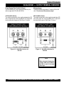
To protect the welder/AC generator from an overload, a 3-pole,
53 amp, main circuit breaker is provided. In addition 2-two
pole, 25 amp breaker is provided for the G.F.C.I. receptacles.
Make sure to switch both circuit breakers to the "OFF"
position prior to starting the engine.
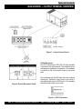
Ground
Extension Cable
The nut and ground terminal on the welder/AC generator
should always be used to connect to a suitable ground. The
ground path should be of #8 size wire.
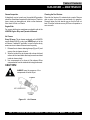
When electric power is to be provided to various tools or loads at
some distance from the welder/AC generator, extension cords
are normally used. Cables should be sized to allow for distance
in length and amperage so that the voltage drop between the
welder/AC generator and point of use (load) is held to a
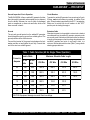
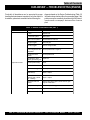
minimum. Use the cable selection chart (Table 7 ) as a guide for
selecting proper cable size.
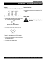
Connect the terminal of the ground wire between the lock
washer and the nut and tighten the nut fully. Connect their
end of the wire to a suitable ground.
Table 7. Cable Selection (60 Hz, Single Phase Operation)
Load In Watts
Current in
Amperes At 120 At 240
Volts
Volts
Maximum Allowable Cable Length
#10 Wire
#12 Wire
#14 Wire
#16 Wire
2.5
300
600
1000 ft.
600 ft.
375 ft.
250 ft.
5
600
1200
500 ft.
300 ft.
200 ft.
125 ft.
7.5
900
1800
350 ft.
200 ft.
125 ft.
100 ft.
10
1200
2400
250 ft.
150 ft.
100 ft.
15
1800
3600
150 ft.
100 ft.
65 ft.
20
2400
4800
125 ft.
75 ft.
50 ft.
CAUTION: Equipment damage can result from low voltage.
BLW-400SSW-WELDER/AC GENERATOR— PARTS & OPERATION MANUAL— REV. #1 (06/15/01) — PAGE 27