1
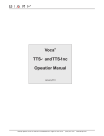
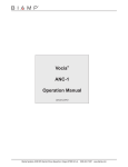
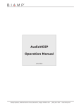
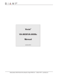
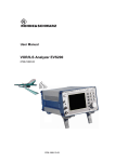
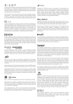
Vocia®
LSI-16
Operation Manual
Biamp Systems, 10074 S.W. Arctic Drive, Beaverton, Oregon 97005 U.S.A. (503) 641-7287 www.biamp.com
table of contents
Vocia Life Safety Interface 16 (LSI-16) features . . . . . . . . . . . . . . . . . . . . . . . . . . . . . . . 3
front panel. . . . . . . . . . . . . . . . . . . . . . . . . . . . . . . . . . . . . . . . . . . . . . . . . . . . . . . . . . . . . . . . . . . . . . . . . . . . . . . . 4-5
Setup and Use. . . . . . . . . . . . . . . . . . . . . . . . . . . . . . . . . . . . . . . . . . . . . . . . . . . . . . . . . . . . . . . . . . . . . . . . . . . . . . . . . . 4
Front Panel . . . . . . . . . . . . . . . . . . . . . . . . . . . . . . . . . . . . . . . . . . . . . . . . . . . . . . . . . . . . . . . . . . . . . . . . . . . . . . . . . . . . 4
(1) Power . . . . . . . . . . . . . . . . . . . . . . . . . . . . . . . . . . . . . . . . . . . . . . . . . . . . . . . . . . . . . . . . . . . . . . . . . . . . . . . . . . . . . . 4
(2) General Alarm. . . . . . . . . . . . . . . . . . . . . . . . . . . . . . . . . . . . . . . . . . . . . . . . . . . . . . . . . . . . . . . . . . . . . . . . . . . . . . . . 4
(3) General Fault . . . . . . . . . . . . . . . . . . . . . . . . . . . . . . . . . . . . . . . . . . . . . . . . . . . . . . . . . . . . . . . . . . . . . . . . . . . . . . . . 4
(4) Power Supply Fault. . . . . . . . . . . . . . . . . . . . . . . . . . . . . . . . . . . . . . . . . . . . . . . . . . . . . . . . . . . . . . . . . . . . . . . . . . . 4
(5) Protection Fault. . . . . . . . . . . . . . . . . . . . . . . . . . . . . . . . . . . . . . . . . . . . . . . . . . . . . . . . . . . . . . . . . . . . . . . . . . . . . . 4
(6) Path Fault. . . . . . . . . . . . . . . . . . . . . . . . . . . . . . . . . . . . . . . . . . . . . . . . . . . . . . . . . . . . . . . . . . . . . . . . . . . . . . . . . . . 4
(7) System Fault . . . . . . . . . . . . . . . . . . . . . . . . . . . . . . . . . . . . . . . . . . . . . . . . . . . . . . . . . . . . . . . . . . . . . . . . . . . . . . 4-5
(8–15) Zone Alarm/Option Slot and (16–23) Zone Fault/Option Slot. . . . . . . . . . . . . . . . . . . . . . . . . . . . . . . . . . . . . . . 5
rear panel. . . . . . . . . . . . . . . . . . . . . . . . . . . . . . . . . . . . . . . . . . . . . . . . . . . . . . . . . . . . . . . . . . . . . . . . . . . . . . . . . 6-11
Device ID . . . . . . . . . . . . . . . . . . . . . . . . . . . . . . . . . . . . . . . . . . . . . . . . . . . . . . . . . . . . . . . . . . . . . . . . . . . . . . . . . . . . . . 6
Network Connection. . . . . . . . . . . . . . . . . . . . . . . . . . . . . . . . . . . . . . . . . . . . . . . . . . . . . . . . . . . . . . . . . . . . . . . . . . . 6-7
Monitored Outputs . . . . . . . . . . . . . . . . . . . . . . . . . . . . . . . . . . . . . . . . . . . . . . . . . . . . . . . . . . . . . . . . . . . . . . . . . . . . . . 8
Sounder Outputs/Silence Input. . . . . . . . . . . . . . . . . . . . . . . . . . . . . . . . . . . . . . . . . . . . . . . . . . . . . . . . . . . . . . . . . . . . 8
System Fault Reset Input. . . . . . . . . . . . . . . . . . . . . . . . . . . . . . . . . . . . . . . . . . . . . . . . . . . . . . . . . . . . . . . . . . . . . . . . . 8
System Test. . . . . . . . . . . . . . . . . . . . . . . . . . . . . . . . . . . . . . . . . . . . . . . . . . . . . . . . . . . . . . . . . . . . . . . . . . . . . . . . . . . . 9
Voice Active Alarm . . . . . . . . . . . . . . . . . . . . . . . . . . . . . . . . . . . . . . . . . . . . . . . . . . . . . . . . . . . . . . . . . . . . . . . . . . . . . . 9
General Fault, PSU Fault, Protection Fault, and Path Fault . . . . . . . . . . . . . . . . . . . . . . . . . . . . . . . . . . . . . . . . . . . . . 9
Control Inputs. . . . . . . . . . . . . . . . . . . . . . . . . . . . . . . . . . . . . . . . . . . . . . . . . . . . . . . . . . . . . . . . . . . . . . . . . . . . . . . . . 10
PSU Fault. . . . . . . . . . . . . . . . . . . . . . . . . . . . . . . . . . . . . . . . . . . . . . . . . . . . . . . . . . . . . . . . . . . . . . . . . . . . . . . . . . . . . 10
Ethernet Fault . . . . . . . . . . . . . . . . . . . . . . . . . . . . . . . . . . . . . . . . . . . . . . . . . . . . . . . . . . . . . . . . . . . . . . . . . . . . . . . . . 10
Voice Alarm Silence from CIE. . . . . . . . . . . . . . . . . . . . . . . . . . . . . . . . . . . . . . . . . . . . . . . . . . . . . . . . . . . . . . . . . . . . . 10
Voice Alarm Reset from CIE. . . . . . . . . . . . . . . . . . . . . . . . . . . . . . . . . . . . . . . . . . . . . . . . . . . . . . . . . . . . . . . . . . . . . . 10
Emergency Detection System Alarm. . . . . . . . . . . . . . . . . . . . . . . . . . . . . . . . . . . . . . . . . . . . . . . . . . . . . . . . . . . . . . . 10
Option Slot. . . . . . . . . . . . . . . . . . . . . . . . . . . . . . . . . . . . . . . . . . . . . . . . . . . . . . . . . . . . . . . . . . . . . . . . . . . . . . . . . . . . 11
System Fault Relay Connection. . . . . . . . . . . . . . . . . . . . . . . . . . . . . . . . . . . . . . . . . . . . . . . . . . . . . . . . . . . . . . . . . . . 11
RS232. . . . . . . . . . . . . . . . . . . . . . . . . . . . . . . . . . . . . . . . . . . . . . . . . . . . . . . . . . . . . . . . . . . . . . . . . . . . . . . . . . . . . . . . 11
24V DC Connector and LED. . . . . . . . . . . . . . . . . . . . . . . . . . . . . . . . . . . . . . . . . . . . . . . . . . . . . . . . . . . . . . . . . . . . . . 11
IP30 Compliance. . . . . . . . . . . . . . . . . . . . . . . . . . . . . . . . . . . . . . . . . . . . . . . . . . . . . . . . . . . . . . . . . . . . . . . . . . . . . . . 11
installation. . . . . . . . . . . . . . . . . . . . . . . . . . . . . . . . . . . . . . . . . . . . . . . . . . . . . . . . . . . . . . . . . . . . . . . . . . . . . . . . . 12
specifications & block diagram. . . . . . . . . . . . . . . . . . . . . . . . . . . . . . . . . . . . . . . . . . . . . . . . . . . . 13
warranty . . . . . . . . . . . . . . . . . . . . . . . . . . . . . . . . . . . . . . . . . . . . . . . . . . . . . . . . . . . . . . . . . . . . . . . . . . . . . . . . . . . . 14
2
Vocia Life Safety Interface 16 (LSI-16)
The LSI-16 is a networked device that serves as an interface between a Vocia system and emergency or fire alarm systems. The LSI-16
may accept up to three sources of power: main power is from an external, standards compliant, battery backed 24V DC source but the LSI16 can also utilize Power over Ethernet (PoE) delivered via either of its two network ports. The device is equipped with parallel I/O ports
for direct interface to fire and emergency control equipment. The LSI-16 uses Ethernet-based control protocols to function within a Vocia
system.
FEATURES
• Parallel I/O ports for direct interface with fire alarm and emergency equipment
• Emergency control of four zones
• Eight monitored outputs and eight control inputs
• Redundant network connection and power supply options
• Option module for added control of I/O
• Power and data over a single Ethernet cable
• Local storage of configuration data
• Rotary switches for unit identification
• Status LEDs
• Rack mountable (1RU)
• CE marked and RoHS compliant
• Covered by Biamp Systems’ warranty
3
lsi-16 front panel
Setup and Use
The Vocia software provides an intuitive interface for configuration and programming of the LSI-16. The information supplied by this manual relates to physical connections and assignment. For more details on configuration of the LSI-16, please consult the Vocia Software Help File.
The LSI-16 governs the emergency functions of a Vocia system, monitoring and reporting faults and alarm conditions through indicators
and the system software. Incorrect configuration, removal, or non-installation of some system elements may result in the LSI-16 reporting
a fault or alarm condition. This is normal operation. For correct, fault-free operation, inputs and outputs must be connected to the LSI-16
as detailed below, the LSI-16 must detect that it is the only such device installed in the Paging World, and the system must be correctly
configured and correctly operating.
Front Panel
The LSI-16 features twenty-three LEDs on the front plate (from left to right):
(LED 1) Power
The first LED on the left will illuminate green if the unit is powered by main or PoE supplies.
(LED 2) General Alarm
This LED will illuminate red if the LSI-16 receives an alarm signal from an external emergency detection system (e.g. a fire alarm system)
via the Alarm inputs to the LSI-16. This LED indicates the general alarm state:
1.Solid red - The LSI-16 has received an alarm signal from an external emergency detection system (e.g. fire alarm system).
2.Flashing red - The LSI-16 has received a general alarm silence from an external emergency detection system (e.g. fire alarm
system).
(LED 3) General Fault
This LED will illuminate yellow if there is a fault in the system that does not affect the delivery of a warning message.
(LED 4) Power Supply Fault
This LED will illuminate yellow if LSI-16 is operating on a PoE supply but the main 24V supply fails or an external power supply fault is signaled
to the LSI-16.
(LED 5) Protection Fault
This LED will illuminate yellow if a system amplifier channel fails and this failure does not prevent an emergency zone voice announcement. Note: failures that do affect emergency zone voice announcements will result in a system fault.
(LED 6) Path Fault
This LED will illuminate yellow if a fault in a transmission path is detected. The path integrity is tested from microphone capsule
to end of loudspeaker lines if optional Vocia ELD-1 devices are fitted at the end of the loudspeaker lines.
(LED 7) System Fault
This LED indicates the integrity of the system:
1. Flashing yellow - The unit has a fault that may prevent the reliable operation of life safety announcement functions.
2. Not illuminated - The unit is operational without any faults that may prevent reliable operation of life safety announcement functions.
4
lsi-16 front panel
(LED 7) System Fault (continued)
Because it indicates a potentially serious condition, the presence of a System Fault extinguishes indicators for PSU, Path and Protection
faults so as to focus attention on the primary fault. However, individual PSU, Path and Protection faults are still shown in the system
software and signaled to individual fault outputs as described below.
The LSI-16 will always power up in the system fault condition. Manual intervention is required to take the LSI-16 out of this condition. Note:
this power up condition does not prevent emergency zone voice announcements provided that the system is operating reliably.
(LEDs 8–15) Zone Alarm/Option Slot and (LEDs 16–23) Zone Fault/Option Slot
These two groups of LEDs indicate functionality of the option slot board, which depends on the type of option module that is fitted
to the LSI-16. If no option slot board is installed, these LEDs will remain inactive.
5
lsi-16 rear panel
BIAMP SYSTEMS
10
Designed in Australia
Assembled in USA
YEL: in use
GRN :link/act
N24138
Option A
Device ID
1
2
4
3
5
6
7
9
8
10 11 12 13 14
1
2
3
4
5
6
7
8
9
Option B
10 11 12 13 14
Model LSI-16
24V DC
15W
GND
1
PoE IEEE 802.3af
Class 3
2
MSB
LSB
1
2
5 6
3 4
Monitored Outputs
7
8 10V
(100mA)
1
2
3
4
5
Control Inputs
6
7
8
C NC NO
System Fault
RS232
Power
Class 2 or LPS
Device ID
The rotary ID switches are located on the back of the LSI-16 and give the unit a unique Device ID. The switches are in hexadecimal format.
All LSI-16 units must have a unique Device ID to function within a Vocia Paging World (i.e., it is not possible to have two LSI-16 units with
the same Device ID of hex 07). To assign a Device ID of hex 07, turn the LSB switch to 7 and leave the MSB switch on 0. To create an ID
of hex B7, turn the LSB switch to 7 and turn the MSB switch to B. Device ID switches should be set using a 0.1 inch (2.5mm) to 0.12 inch
(3.0mm) flat blade screwdriver. More information on setting IDs and the hexadecimal numbering scheme used in Vocia can be found in the
Vocia Help File.
Please note: Changes made to the Device ID while connected to the network require a power cycle in order to take effect.
Network Connection
The LSI-16 has two RJ45 Ethernet connectors. These provide redundant network capability as well as a secondary source of power
(PoE). If communication is lost on either Ethernet port, the LSI-16 reports a fault. For this reason, both Ethernet ports must be connected
to the Vocia network. To provide Auxiliary power PoE should be supplied to both Ethernet ports. An LED adjacent to each RJ45 connector
indicates that PoE is being supplied via that port.
The RJ45 connectors utilize standard copper Ethernet cabling to interface the LSI-16 to the Vocia system via a PoE-compliant
network switch. The RJ45 connector provides two LEDs that indicate Ethernet link and network activity (see table below).
Left LED
Right LED
Description
None
None
No power or data connectivity. Please check the PoE network connection.
Yellow
Flashing
green
Network link established and indicates the port is currently in use.
Yellow
None
There is a network link but the port is redundant.
6
lsi-16 rear panel
This connection carries control data and power over a single Ethernet cable. The maximum distance between any unit and an Ethernet
switch is 328 feet (100 meters) when using copper cabling. Additional Ethernet switches and/or fiber-optic cable can be used to further
extend distances between units on a network. Note: A managed Ethernet switch is required for redundant network wiring (spanning-tree
configuration or similar).
If non-Vocia network traffic shares an Ethernet switch with the Vocia network, separate VLANs must be established. All Ethernet wiring
must be accomplished using shielded CAT5, CAT5e, CAT6, or CAT7 cable.
For standards-compliant systems, a managed switch with dry contact fault output is required.
LSI-16
BIAMP SYSTEMS
10
Designed in Australia
Assembled in USA
YEL: in use
GRN :link/act
N24138
Option A
Device ID
1
2
4
3
5
6
7
8
9
10 11 12 13 14
1
2
3
4
5
6
7
8
9
Model LSI-16
Option B
10 11 12 13 14
24V DC
15W
GND
1
PoE IEEE 802.3af
Class 3
2
MSB
1
LSB
2
5 6
3 4
Monitored Outputs
7
8 10V
1
(100mA)
2
3
4
5
Control Inputs
6
7
8
C NC NO
System Fault
Power
RS232
Class 2 or LPS
Ethernet switch
with PoE
LSI-16
BIAMP SYSTEMS
10
Designed in Australia
Assembled in USA
YEL: in use
GRN :link/act
N24138
Option A
Device ID
1
2
4
3
5
6
7
8
9
10 11 12 13 14
1
2
3
4
5
6
7
8
9
Model LSI-16
Option B
10 11 12 13 14
24V DC
15W
GND
1
PoE IEEE 802.3af
Class 3
2
MSB
LSB
1
2
5 6
3 4
Monitored Outputs
7
8 10V
(100mA)
1
2
3
4
5
Control Inputs
6
7
8
C NC NO
System Fault
RS232
Power
Class 2 or LPS
Ethernet switch
without PoE
PoE
injector
7
AC Power
lsi-16 rear panel
Monitored Outputs
Two black five-position connectors are located next to the rotary switches. These are predominantly used for Monitored Outputs to external
lamps or sounders. Individual connections are labeled 1 through 8 as indicated below. One connection is configured for use as both an
input and an output (1) and one as an input (2) (see table below for connector assignments).
Marking
Function
Ground
1
Sounder Output / Silence Input
2
System Fault Reset Input
3
Voice Alarm Active
4
General Fault
5
PSU Fault
6
Protection Fault
7
Path Fault
8
External Supply Over-voltage Monitor
10V
10V Out
The outputs will sink current (pull low) when active (see the Specifications section of this document for more details). The desired load
(lamp, LED, etc.) must be connected between the output terminal and a positive voltage reference.
It should be noted that external switches and a sounder connected to the first two inputs are typically mandatory for standards compliance.
The location and physical attributes of these items may be required to conform with local norms. The switches and sounder must be wired
according to the connection diagram provided below.
Sounder Output / Silence Input
This connection functions as a dual purpose alarm sounder output and silence input (see connection diagram below).
Sounder Output
This output connects to a local sounder for fault and alarm warnings. A sounder is typically required for standards compliance.
Note:If an emergency microphone is located near the sounder, it may be configured in Vocia software to mute the sounder while making live announcements.
Silence Input
This input is used to silence the local sounder. The sounder will restart in response to any new fault or alarm.
System Fault Reset Input
This input is required to take the LSI-16 out of System Fault condition. Note: the LSI-16 will always power up in a system fault state (see
connection diagram).
8
lsi-16 rear panel
System Test
A system test can be initiated by simultaneously connecting monitored outputs 1 and 2 to ground (see connection diagram). A system test
runs a diagnostic test, part of which illuminates each LED in turn and momentarily activates the sounder.
Connection Diagram: External Switches and Sounder (Note: 10V supply may be derived from the LSI-16 Outputs Connector)
SW1
System Fault Reset (e.g. EAO 31-453 or equivalent switch)
SW2
System Test (e.g. EAO 31-453 or equivalent switch)
SW3
Silence Local Sounder (e.g. EAO 31-453 or equivalent switch)
D1 and D2
1N4004 or equivalent general purpose 1A diode
R1 and R2
22kΩ 0.25 watt resistor
S1
Piezo (or similar) sounder - tone and sound pressure level may be required to
comply with local norms
Voice Alarm Active
This output is active when messages are playing in response to an alarm input. This output provides indication of when a message is
playing or when a message has been muted.
Constant active output - indicates a message is playing in response to an alarm input.
Cyclic output (1.25Hz) - indicates the message has been muted.
General Fault, PSU Fault, Protection Fault and Path Fault
These outputs will be activated by the same alarm conditions as identically named LEDs on the front panel (described above). Note
however that these outputs will be activated by the faults listed above irrespective of whether a System Fault has been activated.
The Voice Alarm Active, General Fault, PSU Fault, Protection Fault and Path Fault outputs are monitored for open-circuit or short-circuit to
ground or power supply and for over-voltage on the output pin (>35V DC). If incorrect conditions are detected a Fault is signaled. Output
monitoring facilitates compliance with voice evacuation standards.
For each of these outputs, a load must be connected between each output and the positive voltage source. If any output on terminals 1
through 8 is unused, the output must be connected through an external resistor to the positive side of the voltage source (either 10V Out or
user-supplied external source). To ensure correct functionality, the value of each resistor should be 22kΩ. An internally derived 10V source
is provided at the 10V Out terminal; however, the total current available from this pin is limited to 100mA. This voltage source may be used
for external devices provided the total load is less than 100mA. For higher-current devices, a user-supplied external voltage source of up to
35V may be used, with the negative side connected to the pin. Due to monitoring constraints, it is impossible to use both the internal 10V
source and an external source. For monitoring purposes, the positive side of the voltage source (either 10V Out or user-supplied external
source) must be connected to the External Supply Over-voltage Monitor (terminal 8), as well as supplying voltage to external devices.
9
lsi-16 rear panel
Control Inputs
Two five-position plug-in barrier strip connectors provide control input connections. Eight separate channels plus two ground pins are
provided (see table below for connector assignments). Control inputs are fully isolated from all connections in the LSI-16.
Marking
Function
Ground
1
PSU Fault (contact closure indicates a PSU Fault)
2
Ethernet Fault
3
Voice Alarm Silence from CIE (common for all zones)
4
Voice Alarm Reset from CIE (common for all zones)
Ground
5
Emergency Detection System Alarm 1
6
Emergency Detection System Alarm 2
7
Emergency Detection System Alarm 3
8
Emergency Detection System Alarm 4
Input Activation Conditions
Control Inputs 1 and 2
To activate an input, it must be connected to an external circuit that returns to either of the two
be less than 4kΩ.
pins. The resistance of this circuit must Control Inputs 3 to 8
These inputs must be permanently connected to an external circuit that returns to either of the two pins. The resistance of this circuit must be between 1kΩ and 4kΩ. To activate an input, pull the input to a voltage between 12 and 24V.
PSU Fault
This input may be derived from the primary 24V power supply to indicate to the LSI-16 if there is a fault in the power supply.
This may be required for standards compliance.
Ethernet Fault
This input can be derived from an Ethernet switch to monitor the Ethernet network connection between the LSI-16 and amplifier. This may
be required for standards compliance.
Voice Alarm Silence from CIE (fire alarm system)
This input is a signal from the CIE (fire alarm system) that will mute emergency messages in all emergency zones.
Voice Alarm Reset from CIE (fire alarm system)
This input is a signal from the CIE (fire alarm system) that will reset emergency messages in all emergency zones.
Emergency Detection System Alarm
These four inputs are used to connect to the fire alarm control and indicating equipment (CIE) and notify the LSI-16 that an alarm has
occurred on a particular zone. Four such zone inputs may be connected. Additional zone inputs will be available through the option module.
When an alarm is detected, the Vocia system will enter Emergency Mode as configured for that input. During Emergency Mode, some
or all of the Vocia system will cease normal operation and operate as programmed for the emergency.
10
lsi-16 rear panel
Option Slot
The option slot allows for additional modules if required by the system design. A typical option module in this slot may provide eight
additional general purpose logic inputs, plus eight general purpose logic outputs.
System Fault Relay Connection
This relay is activated when the LSI-16 is fully operational. It may be used for informing external devices about the LSI-16’s operating
conditions or sounding an alarm that indicates the LSI-16 is not functioning reliably.
RS232
This port may be used for RS232 communication with the LSI-16 under special circumstances. Future implementations may provide
enhanced features via this port.
24V DC Connector and LED
This is the primary (main) power supply input for the LSI-16 and as such must be fed from a suitable source of 24V DC capable of 15 watts
(625mA). The 24V DC supply has to be sourced separately. In typical installations, this supply will be provided from a power supply
compliant with local norms and required standards (typically battery-backed). The adjacent LED indicates the presence of power.
IP30 Compliance
The LSI-16 is designed for ingress protection to the IP30 standard. In order to maintain this compliance, any unused terminal connectors
on the back of the unit must be fitted with the supplied terminal blocks.
11
lsi-16 installation
Installation
The LSI-16 requires one 1.75 inches (44.45mm) high and 19 inches (483mm) wide rack space with 10 inches (254mm) depth. Mounting
the unit using four screws with washers will prevent marring of the front panel. PVC or nylon washers are appropriate.
Please install the unit away from heat sources, such as vents and radiators, and in rooms with adequate ventilation. Ensure that air can
circulate freely behind, beside, and above the unit. Do not exceed the maximum ambient operating temperature of 32-113 degrees F (045°C). Be aware of conditions in an enclosed rack that may cause the temperature to exceed ambient room conditions.
Note: To operate correctly, the LSI-16 requires input and output connections to external components and devices as described in this
manual.
12
lsi-16 specifications
Life Safety Interface 16 SPECIFICATIONS
System Fault Relay:
Type:
Single ‘Form C’ voltage-free
SPST change-over contact
Load:
Maximum operating voltage:
Maximum operating current:
Maximum switching capacity:
Minimum permissible load:
Resistive
125VAC, 60VDC
600mA AC, 1A DC
37.5VA, 30W
10µA @ 10mVDC
Parallel Control Inputs:
Number:
Type:
Cathode presented at input –
pull low to enable. Sink Current:
Min:
Max:
Maximum Terminal Voltage:
Isolation:
Parallel Control Outputs:
Number:
Type:
Eight
Opto Isolator LED
1mA
6mA
24V
3kV
RS232 Port
Type:
Baud Rate:
DTE
57600
Connection:
RJ45 with shielded Ethernet/PoE cable
(Cat5, Cat5e, Cat6, or Cat7)
Power:
Main:
PoE:
24V DC 15W
802.3af Class 3
Base Dimensions:
Height:
Width:
Depth:
1.75 inches (44.5mm)
19 inches (483mm)
10 inches (254mm
Weight:
Eight
FET switch, open drain
(low side driver)
Maximum Continuous Current:
Current Limit:
Maximum External Supply:
VMon Input Shutdown:
0.35A
0.8A
35V
35V
Approx 6.4 lbs. (2.8kg)
Ambient Operating
Temperature Range:
Compliance:
32-113 degrees F (0-45 degrees C)
EU Directive 2002/95/EC, RoHS directive
CE marked
Life Safety Interface 16 Block Diagram
LEDs
Control Inputs
ID Switches
Control Outputs
HostProcessor
Option Slot
PoE
24V DC
Vocia System
control data
585.0245.90A
13
LSI-16 warranty
BIAMP SYSTEMS IS PLEASED TO EXTEND THE FOLLOWING 5-YEAR LIMITED WARRANTY TO THE ORIGINAL PURCHASER OF
THE PROFESSIONAL SOUND EQUIPMENT DESCRIBED IN THIS MANUAL
1. BIAMP Systems warrants to the original purchaser of new products that the product will be free from defects in material and
workmanship for a period of 5 YEARS from the date of purchase from an authorized BIAMP Systems dealer, subject to the
terms and conditions set forth below.
2 If you notify BIAMP during the warranty period that a BIAMP Systems product fails to comply with the warranty, BIAMP Systems
will repair or replace, at BIAMP Systems’ option, the nonconforming product. As a condition to receiving the benefits of this warranty,
you must provide BIAMP Systems with documentation that establishes that you were the original purchaser of the products. Such
evidence may consist of your sales receipt from an authorized BIAMP Systems dealer. Transportation and insurance charges to
and from the BIAMP Systems factory for warranty service shall be your responsibility.
3. This warranty will be VOID if the serial number has been removed or defaced; or if the product has been altered, subjected to
damage, abuse or rental usage, repaired by any person not authorized by BIAMP Systems to make repairs; or installed in any
manner that does not comply with BIAMP Systems’ recommendations.
4. Electro-mechanical fans, electrolytic capacitors, gooseneck microphones, cords connecting handheld microphones, hard-drives,
displays, and normal wear and tear of items such as paint, knobs, handles, keypads and covers are not covered under this warranty. All server-based devices are warranted for 3 years only.
5. This warranty is in lieu of all other warranties, expressed or implied. Biamp Systems disclaims all other warranties, expressed or
implied, including, but not limited to, implied warranties of merchantability and fitness for a particular purpose.
6. The remedies set forth herein shall be the purchaser’s sole and exclusive remedies with respect to any defective product.
7. No agent, employee, distributor or dealer of BIAMP Systems is authorized to modify this warranty or to make additional warranties on behalf of BIAMP Systems. Statements, representations or warranties made by any dealer do not constitute warranties by
BIAMP Systems. BIAMP Systems shall not be responsible or liable for any statement, representation or warranty made by any
dealer or other person.
8. No action for breach of this warranty may be commenced more than one year after the expiration of this warranty.
9. BIAMP Systems shall not be liable for special, indirect, incidental, or consequential damages, including lost profits or loss of use arising out of the purchase, sale, or use of the products, even if biamp Systems was advised of the possibility of such damages.
14
compliance
15
compliance
16