1
AirLink Helix
User Guide
2140847
Rev 3.0D
Preface
Important
Notice
Due to the nature of wireless communications, transmission and reception of data
can never be guaranteed. Data may be delayed, corrupted (i.e., have errors) or
totally lost. Although significant delays or losses of data are rare when wireless
devices such as the Sierra Wireless AirLink Product Name are used in a normal
manner with a well-constructed network, the Sierra Wireless AirLink Product
Name should not be used in situations where failure to transmit or receive data
could result in damage of any kind to the user or any other party, including but not
limited to personal injury, death, or loss of property. Sierra Wireless accepts no
responsibility for damages of any kind resulting from delays or errors in data
transmitted or received using the Sierra Wireless AirLink Product Name, or for
failure of the Sierra Wireless AirLink Product Name to transmit or receive such
data.
Safety and
Hazards
READ ALL SAFETY AND OPERATING INSTRUCTIONS BEFORE OPERATING
THE PRODUCT.
Warning: FOR INDOOR USE ONLY. TO PREVENT FIRE OR SHOCK HAZARD, DO
NOT EXPOSE THIS DEVICE TO RAIN OR MOISTURE. DO NOT EXPOSE THIS
PRODUCT TO DRIPPING OR SPLASHING. NO OBJECTS FILLED WITH LIQUIDS,
SUCH AS VASES, SHALL BE PLACED ON THE DEVICE.
Caution: DO NOT OPEN THE UNIT. DO NOT PERFORM ANY SERVICING OTHER
THAN THAT CONTAINED IN THE INSTALLATION AND TROUBLESHOOTING
INSTRUCTIONS UNLESS YOU ARE QUALIFIED TO DO SO. REFER ALL SERVICING
TO QUALIFIED SERVICE PERSONNEL.
Caution: CHANGES OR MODIFICATIONS NOT EXPRESSLY APPROVED BY THE
PARTY RESPONSIBLE FOR COMPLIANCE COULD VOID THE USER’S AUTHORITY
TO OPERATE THE EQUIPMENT.
It is recommended that the customer install an AC surge arrestor in the AC outlet
to which this device is connected. This is to avoid damaging the equipment by
local lightning strikes and other electrical surges.
Only use twisted pair Ethernet cables with RJ-45 connectors that conform to FCC
standards in the Ethernet ports. Do not plug a telephone cable (RJ-11) into any
Ethernet (RJ-45) port on your device.
Installation of this product must be in accordance with national wiring codes.
To clean, wipe this device with a clean, dry cloth. Never use cleaning fluid or
similar chemicals. Do not spray cleaners directly on the unit or use forced air to
remove dust.
Do not use attachments not recommended by the device manufacturer.
To avoid injury from falling equipment, do not place this product on an unstable
surface.
This device should be situated away from heat sources and products that produce
heat.
Rev 3.0D May.10
3
AirLink Helix User Guide
All safety and operating instructions should be retained for future reference.
Do not use onboard aircraft or in hazardous locations such as gas stations or
explosive environments.
Not designed, manufactured or intended for machinery, medical, or industrial
applications or for any other application may be hazardous.
Do not move or touch the antennas while the device is on. Device should be
located at least 20 centimeters (8 inches) away from any human body in order to
meet FCC exposure limits.
Do not operate while driving.
Regulatory
Information
This device complies with Part 15 of the FCC Rules. Operation is subject to the
following two conditions:
1. This device may not cause harmful interference; and
2. This device must accept any interference received, including interference that
may cause undesired operation.
This equipment has been tested and found to comply with the limits for a Class B
digital device, pursuant to part 15 of the FCC Rules. These limits are designed to
provide reasonable protection against harmful interference in a residential
installation. This equipment generates, uses and can radiate radio frequency
energy and, if not installed and used in accordance with the instructions, may
cause harmful interference to radio communications. However, there is no
guarantee that interference will not occur in a particular installation. If this
equipment does cause harmful interference to radio or television reception, which
can be determined by turning the equipment off and on, the user is encouraged to
try to correct the interference by one or more of the following measures:
•
Reorient or relocate the receiving antenna.
•
Increase the separation between the equipment and receiver.
•
Connect the equipment into an outlet on a circuit different from that to which
the receiver is connected.
•
Consult the dealer or an experienced radio/TV technician for help.
The device that accompanies this software can radiate radio frequency energy. If
not used in accordance with the instructions given in the User Guide, the device
may cause harmful interference with other communications devices (for example
radios, televisions, phones, etc.).
Any changes or modifications not expressly approved by Sierra Wireless could
void the user's authority to operate this device.
Sierra Wireless America, 39677 Eureka Drive, Newark, CA
(510.624.4900).
Open Source
4
USA, 94560
Certain components of the software included with the Helix RT are subject to the
GNU General Public License ("GPL"), the Lesser GNU General Public License
("LGPL"), or other "open source" or "free software" licenses ("Open Source
Software"). Some of the Open Source license is owned by third parties. Each item
of Open Source Software is licensed under the terms of the end-user license that
accompanies such Open Source Software. Nothing in this document limits your
2140847
Preface
rights under, or grants you rights that supersede, the terms and conditions of any
applicable Open Source License. In particular, nothing in this document restricts
your right to copy, modify, and distribute that Open Source Software subject to the
terms of Open Source License. As required by the terms of the GPL and LGPL or
any other applicable Open Source License, Sierra Wireless makes the Open
Source Software available to the public in source code form on a CD. To receive a
CD, please contact customer support.
The following Open Source Software is included with the Helix RT.
Patents
•
GPL and LGPL Software. The Helix RT is provided with the following software
licensed under the GPL and LGPL. A copy of the GNU GPL license is
available from the Free Software Foundation (http://www.gnu.org).
· BusyBox from Erik Andersen (http://www.busybox.net)
· Host AP driver from Jouni Malinen (http://hostap.epitest.fi)
· IPtables from Harald Welte and others (http://www.netfilter.org)
· Linux operating system version 2.4.20
· Openswan from Xelerance Corporation (http://www.openswan.org)
· PPP from Paul Mackerras (http://www.samba.org/ftp/unpacked/ppp/
· README)
· SPLASH from Willem de Bruijn (http://splash-snap.sourceforge.net)
· Updatedd from Philipp Benner (http://www.philipp-benner.de/updatedd)
•
Other Open Source Software. The Helix RT is provided with the following
software licensed under BSD licenses or other Open Source Licenses. The
software and license details are available from the referenced web sites.
· Internet Software Consortium DHCP Server (http://www.isc.org)
· Net-SNMP from the NET-SNMP Project (http://www.net-snmp.org)
· OpenSSH from the OpenBSD Project (http://www.openssh.com)
· thttpd from Jef Poskanzer (http://www.acme.com)
Portions of this product may be covered by some or all of the following US
patents:
5,515,013
6,191,741
6,653,979
6,968,171
D459,303
5,629,960
6,199,168
6,697,030
6,985,757
5,845,216
6,339,405
6,785,830
7,023,878
5,847,553
6,359,591
6,845,249
7,053,843
5,878,2345,890,0575,929,8156,169,884
6,400,3366,516,2046,561,8516,643,501
6,847,8306,876,6976,879,5856,886,049
7,106,5697,145,2677,200,512D442,170
and other patents pending.
Copyright
2004-2009 Sierra Wireless America, Inc.
Trademarks
AirLink™ and AceWare™ are trademarks of Sierra Wireless.
Helix RT ™ is a trademark os Sierra Wireless.
Windows® is a registered trademark of Microsoft Corporation.
Other trademarks are the property of the respective owners.
Rev 3.0D May.10
5
AirLink Helix User Guide
Contact
Information
Support Desk:
Phone: 1-877-231-1144
Hours: 5:00 AM to 5:00 PM Pacific Time,
Monday to Friday, except US Holidays
E-mail: [email protected]
Sales Desk:
Phone: 1-510-624-4200
1-604-232-1488
Hours: 8:00 AM to 5:00 PM Pacific Time
E-mail: [email protected]
Post: Sierra Wireless America
39677 Eureka Drive
Newark, CA
USA
94560
Sierra Wireless
13811 Wireless Way
Richmond, BC
Canada
V6V 3A4
Fax: 1-510-624-4299
1-604-231-1109
Web: www.sierrawireless.com
Consult our website for up-to-date product descriptions, documentation,
application notes, firmware upgrades, troubleshooting tips, and press releases:
www.sierrawireless.com
Revision
number
6
Release
date
Changes
1.x
2009
AirLink Helix documentation draft created.
2.x
2009
AirLink Helix documentation revised.
3.x
2009
USB Chapter added.
2140847
Contents
Introduction . . . . . . . . . . . . . . . . . . . . . . . . . . . . . . . . . . . . . . . . . . . . . . . . . . . . .5
What’s Included with the AirLink Helix? . . . . . . . . . . . . . . . . . . . . . . . . . . . . . 5
What Else Do You Need to Get Started? . . . . . . . . . . . . . . . . . . . . . . . . . . . . 5
Getting Going (the quick version). . . . . . . . . . . . . . . . . . . . . . . . . . . . . . . . . . 6
CDMA . . . . . . . . . . . . . . . . . . . . . . . . . . . . . . . . . . . . . . . . . . . . . . . . . . . .6
GSM . . . . . . . . . . . . . . . . . . . . . . . . . . . . . . . . . . . . . . . . . . . . . . . . . . . . . .6
Connecting a Computer to the AirLink Helix . . . . . . . . . . . . . . . . . . . . . . . . . .7
Connecting Through Ethernet . . . . . . . . . . . . . . . . . . . . . . . . . . . . . . . . . . . . 7
Connecting Through Wi-Fi . . . . . . . . . . . . . . . . . . . . . . . . . . . . . . . . . . . . . . 8
Where to Find More Help . . . . . . . . . . . . . . . . . . . . . . . . . . . . . . . . . . . . . . . . 8
Hardware Overview . . . . . . . . . . . . . . . . . . . . . . . . . . . . . . . . . . . . . . . . . . . . . .9
Physical Interfaces . . . . . . . . . . . . . . . . . . . . . . . . . . . . . . . . . . . . . . . . . . . . . 9
Turning On the AirLink Helix . . . . . . . . . . . . . . . . . . . . . . . . . . . . . . . . . . . . . 9
Status Lights. . . . . . . . . . . . . . . . . . . . . . . . . . . . . . . . . . . . . . . . . . . . . . . . . . 9
LEDs . . . . . . . . . . . . . . . . . . . . . . . . . . . . . . . . . . . . . . . . . . . . . . . . . . . .10
Cellular Antennas . . . . . . . . . . . . . . . . . . . . . . . . . . . . . . . . . . . . . . . . . . . . . 10
Wi-Fi Antennas . . . . . . . . . . . . . . . . . . . . . . . . . . . . . . . . . . . . . . . . . . . . . . 12
Reset Button. . . . . . . . . . . . . . . . . . . . . . . . . . . . . . . . . . . . . . . . . . . . . . . . . 12
Power Connector . . . . . . . . . . . . . . . . . . . . . . . . . . . . . . . . . . . . . . . . . . . . . 13
SIM Slot . . . . . . . . . . . . . . . . . . . . . . . . . . . . . . . . . . . . . . . . . . . . . . . . . . . . 13
Remove the SIM . . . . . . . . . . . . . . . . . . . . . . . . . . . . . . . . . . . . . . . . . . . 14
USB Connection . . . . . . . . . . . . . . . . . . . . . . . . . . . . . . . . . . . . . . . . . . . . . . . . 15
USB Modem connection. . . . . . . . . . . . . . . . . . . . . . . . . . . . . . . . . . . . . . . . 16
Configuring AirLink Helix . . . . . . . . . . . . . . . . . . . . . . . . . . . . . . . . . . . . . . . . 19
ACEmanager . . . . . . . . . . . . . . . . . . . . . . . . . . . . . . . . . . . . . . . . . . . . . . . . 19
Rev 3.0D May.10
1
Contents
Status . . . . . . . . . . . . . . . . . . . . . . . . . . . . . . . . . . . . . . . . . . . . . . . . . . . . . . 19
Home . . . . . . . . . . . . . . . . . . . . . . . . . . . . . . . . . . . . . . . . . . . . . . . . . . . .19
WAN/Cellular . . . . . . . . . . . . . . . . . . . . . . . . . . . . . . . . . . . . . . . . . . . . . .20
LAN/WiFi . . . . . . . . . . . . . . . . . . . . . . . . . . . . . . . . . . . . . . . . . . . . . . . . .21
VPN . . . . . . . . . . . . . . . . . . . . . . . . . . . . . . . . . . . . . . . . . . . . . . . . . . . . .22
Security . . . . . . . . . . . . . . . . . . . . . . . . . . . . . . . . . . . . . . . . . . . . . . . . . .23
Services . . . . . . . . . . . . . . . . . . . . . . . . . . . . . . . . . . . . . . . . . . . . . . . . . .23
About . . . . . . . . . . . . . . . . . . . . . . . . . . . . . . . . . . . . . . . . . . . . . . . . . . . .24
Configuring WAN/Cellular . . . . . . . . . . . . . . . . . . . . . . . . . . . . . . . . . . . . . . . .25
WAN/Cellular . . . . . . . . . . . . . . . . . . . . . . . . . . . . . . . . . . . . . . . . . . . . . . . . 25
WAN Failover . . . . . . . . . . . . . . . . . . . . . . . . . . . . . . . . . . . . . . . . . . . . . .26
Setup . . . . . . . . . . . . . . . . . . . . . . . . . . . . . . . . . . . . . . . . . . . . . . . . . 27
How it works . . . . . . . . . . . . . . . . . . . . . . . . . . . . . . . . . . . . . . . . . . . 28
IP Passthrough . . . . . . . . . . . . . . . . . . . . . . . . . . . . . . . . . . . . . . . . . . . . .28
Configuring LAN/WiFi . . . . . . . . . . . . . . . . . . . . . . . . . . . . . . . . . . . . . . . . . . . .29
LAN/WiFi . . . . . . . . . . . . . . . . . . . . . . . . . . . . . . . . . . . . . . . . . . . . . . . . . . . 29
Addressing/VLAN . . . . . . . . . . . . . . . . . . . . . . . . . . . . . . . . . . . . . . . . . . .29
WiFi Global . . . . . . . . . . . . . . . . . . . . . . . . . . . . . . . . . . . . . . . . . . . . . . . .30
Shared WEP . . . . . . . . . . . . . . . . . . . . . . . . . . . . . . . . . . . . . . . . . . . 31
WPA/WPA2 Personal . . . . . . . . . . . . . . . . . . . . . . . . . . . . . . . . . . . . 32
WPA Enterprise . . . . . . . . . . . . . . . . . . . . . . . . . . . . . . . . . . . . . . . . . 33
WiFi 2 . . . . . . . . . . . . . . . . . . . . . . . . . . . . . . . . . . . . . . . . . . . . . . . . . . . .34
Global DNS . . . . . . . . . . . . . . . . . . . . . . . . . . . . . . . . . . . . . . . . . . . . . . .34
VRRP . . . . . . . . . . . . . . . . . . . . . . . . . . . . . . . . . . . . . . . . . . . . . . . . . . . . . . 35
Configuring AirLink Helix . . . . . . . . . . . . . . . . . . . . . . . . . . . . . . . . . . . . . . . . .37
VPN . . . . . . . . . . . . . . . . . . . . . . . . . . . . . . . . . . . . . . . . . . . . . . . . . . . . . . . 37
VPN 1 . . . . . . . . . . . . . . . . . . . . . . . . . . . . . . . . . . . . . . . . . . . . . . . . . . . .37
VPN 2 . . . . . . . . . . . . . . . . . . . . . . . . . . . . . . . . . . . . . . . . . . . . . . . . . . . .39
Rev 3.0D May.10
2
Contents
Configuring Security . . . . . . . . . . . . . . . . . . . . . . . . . . . . . . . . . . . . . . . . . . . . 41
Security . . . . . . . . . . . . . . . . . . . . . . . . . . . . . . . . . . . . . . . . . . . . . . . . . . . . 41
Port Forwarding and DMZ . . . . . . . . . . . . . . . . . . . . . . . . . . . . . . . . . . . . 41
Port Filtering - Outbound . . . . . . . . . . . . . . . . . . . . . . . . . . . . . . . . . . . . . 42
MAC Filtering . . . . . . . . . . . . . . . . . . . . . . . . . . . . . . . . . . . . . . . . . . . . . . 42
Configuring Services . . . . . . . . . . . . . . . . . . . . . . . . . . . . . . . . . . . . . . . . . . . . 43
. . . . . . . . . . . . . . . . . . . . . . . . . . . . . . . . . . . . . . . . . . . . . . . . . . . . . . . . . . . 43
Services . . . . . . . . . . . . . . . . . . . . . . . . . . . . . . . . . . . . . . . . . . . . . . . . . . . . 43
ACEnet . . . . . . . . . . . . . . . . . . . . . . . . . . . . . . . . . . . . . . . . . . . . . . . . . . . 43
ACEmanager . . . . . . . . . . . . . . . . . . . . . . . . . . . . . . . . . . . . . . . . . . . . . . 44
Dynamic DNS . . . . . . . . . . . . . . . . . . . . . . . . . . . . . . . . . . . . . . . . . . . . .44
Landing Page . . . . . . . . . . . . . . . . . . . . . . . . . . . . . . . . . . . . . . . . . . . . . . 45
Management (“SNMP) . . . . . . . . . . . . . . . . . . . . . . . . . . . . . . . . . . . . . . . . . 45
Configuring Admin . . . . . . . . . . . . . . . . . . . . . . . . . . . . . . . . . . . . . . . . . . . . . . 47
Admin . . . . . . . . . . . . . . . . . . . . . . . . . . . . . . . . . . . . . . . . . . . . . . . . . . . . . . 47
Defaults . . . . . . . . . . . . . . . . . . . . . . . . . . . . . . . . . . . . . . . . . . . . . . . . . . 47
Debug . . . . . . . . . . . . . . . . . . . . . . . . . . . . . . . . . . . . . . . . . . . . . . . . . . . 48
Log . . . . . . . . . . . . . . . . . . . . . . . . . . . . . . . . . . . . . . . . . . . . . . . . . . . . . . 49
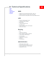
Technical Specifications . . . . . . . . . . . . . . . . . . . . . . . . . . . . . . . . . . . . . . . . . 51
WAN . . . . . . . . . . . . . . . . . . . . . . . . . . . . . . . . . . . . . . . . . . . . . . . . . . . . . . . 51
LAN . . . . . . . . . . . . . . . . . . . . . . . . . . . . . . . . . . . . . . . . . . . . . . . . . . . . . . . 51
Routing . . . . . . . . . . . . . . . . . . . . . . . . . . . . . . . . . . . . . . . . . . . . . . . . . . . . . 51
Administration. . . . . . . . . . . . . . . . . . . . . . . . . . . . . . . . . . . . . . . . . . . . . . . . 51
Hardware . . . . . . . . . . . . . . . . . . . . . . . . . . . . . . . . . . . . . . . . . . . . . . . . . . . 52
Physical . . . . . . . . . . . . . . . . . . . . . . . . . . . . . . . . . . . . . . . . . . . . . . . . . . . . 52
Rev 3.0D May.10
3
AirLink Helix User Guide
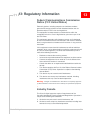
Regulatory Information . . . . . . . . . . . . . . . . . . . . . . . . . . . . . . . . . . . . . . . . . . 53
Federal Communications Commission Notice (FCC United States) . . . . 53
Industry Canada . . . . . . . . . . . . . . . . . . . . . . . . . . . . . . . . . . . . . . . . . . . 53
Antenna Considerations . . . . . . . . . . . . . . . . . . . . . . . . . . . . . . . . . . 54
RF Exposure . . . . . . . . . . . . . . . . . . . . . . . . . . . . . . . . . . . . . . . . . . . . . . 54
EU . . . . . . . . . . . . . . . . . . . . . . . . . . . . . . . . . . . . . . . . . . . . . . . . . . . . . . 54
WEEE Notice . . . . . . . . . . . . . . . . . . . . . . . . . . . . . . . . . . . . . . . . . . 55
4
2140847
1
1: Introduction
• What’s Included
with the AirLink
Helix?
• What Else Do You
Need to Get
Started?
• Getting Going (the
quick version)
The AirLink Helix enables computers and other devices to connect
quickly and easily to the Internet and remote enterprise networks
using cellular data networks.
This User Guide provides basic instructions on how to configure and
operate your AirLink Helix. For additional support please visit
www.sierrawireless.com/support.
What’s Included with the AirLink
Helix?
•
AirLink Helix RT kit
•
AirLink Helix RT cellular router
•
User Guide
•
Outlet power adapter
•
Wi-Fi (optional depending on the kit)
•
Antennas (optional depending on the kit)
What Else Do You Need to Get
Started?
•
An active data account with your cellular provider is required.
Contact your cellular carrier or reseller if you have data account
related queries.
Note: Please also read the terms and conditions of your cellular service to
ensure that your rate plan is appropriate for use with the AirLink Helix.
Rev 3.0D May.10
•
At least one computer that supports Ethernet or Wi-Fi
networking.
•
A web browser such as Internet Explorer 6 or later for Windows,
Firefox 1.5, or Safari.
5
AirLink Helix User Guide
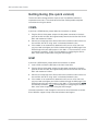
Getting Going (the quick version)
The AirLink Helix is designed to be simple to use. No additional software is
required for most users. The remainder of the User Guide provides complete
instructions for using the device.
CDMA
If you have a CDMA device, please follow the instructions as below:
1. Plug the AirLink Helix power adapter into the power connector on the back
panel of the AirLink Helix. Wait approximately two minutes to allow the AirLink
Helix and modem to initialize.
2. Connect your computer to the AirLink Helix with an ethernet cable. Users can
also connect with Wi-Fi using “helix” as the default network name.
3. If the modem is not automatically detected, and if you are a first time user,
you may need to configure your cellular modem through the WAN page in the
ACEmanager with your web browser at 192.168.2.1. The username is admin
and default password is 12345. For more details on configuring the AirLink
Helix, refer to the chapter titled “Using the ACEmanager.”
GSM
If you have a GSM device, please follow the instructions as below:
1. Insert a SIM card into the SIM slot on the front of the Helix.
2. Plug the AirLink Helix power adapter into the power connector on the back
panel of the AirLink Helix. Wait approximately two minutes to allow the AirLink
Helix and modem to initialize.
3. Connect your computer to the AirLink Helix with an ethernet cable. Users can
also connect with Wi-Fi using “helix” as the default network name.
4. If the modem is not automatically detected, and if you are a first time user,
you may need to configure your cellular modem through the WAN page in the
ACEmanager with your web browser at 192.168.2.1. The username is admin
and default password is 12345. For more details on configuring the AirLink
Helix, refer to the chapter titled “Using the ACEmanager.”
Have more questions? Look through this manual for more information or contact
Sierra Wireless support at http://www.sierrawireless.com/support.
6
2140847
2: Connecting a Computer to the AirLink 2
Helix
• Connecting
Through Ethernet
• Connecting
Through Wi-Fi
• Where to Find More
Help
Any laptop, desktop, handheld, printer, or other computing device that
supports Ethernet (or optional Wi-Fi) can connect to the AirLink Helix.
If your computer supports these common network interfaces, you
don’t need to install any additional software to connect to the AirLink
Helix.
Before connecting multiple devices to the AirLink Helix for the first
time, it is a good idea to connect one computer first and verify that
the Product Name is successfully connected to the Internet. You may
need to use AirLink Helix ACEmanager to verify that the Helix device
is properly configured. See the “Configuring AirLink Helix” chapter for
more information.
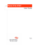
USB port
Serial Port
LAN
Ethernet
LAN/WAN
Ethernet
Power
USB Port
Figure 2-1: Helix: Ports on the backplate
Connecting Through Ethernet
To connect to the AirLink Helix using Ethernet, simply plug one end of
an Ethernet cable into your computer, and plug the other end into
either of the Ethernet ports on the AirLink Helix.
There are two Ethernet ports on the Helix. In most configurations,
both can be used for LAN connections. In WAN failover mode, one is
used for a WAN port to connect to another Internet service like a DSL
or cable modem.
Make sure your computer is setup for DHCP addressing. To setup the
AirLink Helix for static IP addressing, refer to the LAN Page section in
“Using the ACEmanager”.
Rev 3.0D May.10
7
AirLink Helix User Guide
Connecting Through Wi-Fi
Wi-Fi is available as an option on some versions of the Helix RT.
To connect wirelessly to the AirLink Helix using a Wi-Fi equipped computer,
simply select the network name “helix” using the Wi-Fi connection software
provided with your operating system or Wi-Fi network interface.
You can customize the network name and other Wi-Fi configuration options using
the LAN/Wi-Fi page in the ACEmanager. For more information, see the “Using the
ACEmanager” chapter.
Note: If you don’t change the default security settings in the ACEmanager for the AirLink
Helix, the AirLink Helix is accessible to any Wi-Fi device. For information about Wi-Fi
security, see the Security Page section in the “Using ACEmanager” chapter.
The AirLink Helix Wi-Fi network is based on the 802.11b/g. By default you can
also use computers equipped with 802.11b Wi-Fi hardware because 802.11g is
backwards compatible with 802.11b.
If you have trouble connecting automatically to the AirLink Helix using Wi-Fi, try
the following:
•
Make sure the “helix” network name is selected in the list of available
networks with your computer’s Wi-Fi connection software.
•
Turn your computer’s Wi-Fi connection off and then on again.
•
Restart your computer.
•
Check to see that your computer’s network configuration is consistent with the
configuration of the AirLink Helix. The default AirLink Helix configuration
requires your computer to use a DHCP connection.
•
For Windows XP users, check to see that you have Service Pack 2 or higher
installed. To determine if you have Service Pack 2 installed, open the Control
Panel and then open the System application.
•
Change the Wi-Fi channel in the AirLink Helix ACEmanager. You may be
encountering interference on a certain channel.
•
Try turning off WEP or WPA encryption in the ACEmanager. If you can
connect when encryption is turned off, you may be entering incorrect WPA or
WEP login information into your computer or device.
Where to Find More Help
The Ethernet, Wi-Fi, and TCP/IP network interfaces used by the AirLink Helix
comply with industry standards. Connection issues may be related to the proper
use of these standards and not the AirLink Helix itself. For additional help
connecting your computer or device to the AirLink Helix, please refer to the
networking instructions provided by your computer’s operating system.
Please contact Sierra Wireless support for further Helix RT related queries.
8
2140847
3
3: Hardware Overview
• Physical Interfaces
• Turning On the
AirLink Helix
• Status Lights
• Cellular Antennas
• Wi-Fi Antennas
• Reset Button
• Power Connector
• SIM Slot
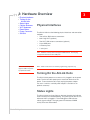
Physical Interfaces
The AirLink Helix has the following physical interfaces and connection
methods:
•
Two cellular SMA antenna connectors
•
802.11b/g Wi-Fi (optional)
•
Two Wi-Fi SMA antenna connectors (optional)
•
2 host USB ports
•
2 Ethernet ports
•
1 serial port
Note: Software currently does not support USB services. Do not plug
unsupported devices into the USB ports.
Note: An ALEOS update
support USB is expected
by September 2009.
Note: Serial connection is for modem programming purposes only.
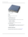
Turning On the AirLink Helix
The AirLink Helix powers on as soon as it is plugged in to the power
outlet. The AirLink Helix power port is located on the back of the
device. To turn the device off, simply unplug the power adapter.
For use in a vehicle, a vehicle power adapter is available as an
optional accessory.
Status Lights
The AirLink Helix has three lights on the front faceplate that indicate
status and help initial troubleshooting. The green LED on the left, is lit
whenever Helix is plugged in. The middle green LED indicates
cellular signal strength. The right green LED indicates WWAN
activity.There are three modes:
Rev 3.0D May.10
9
AirLink Helix User Guide
3G
Signal Strength
WWAN
Status
Figure 3-1: Status LEDs
LEDs
The LED patterns in the Helix are as follows:
(Left) – 3G
•
Off : 3G connection is not active
•
On : 3G connection is active
(Middle) – Signal Strength (RSSI)
•
On Solid : Equal to or stronger than -69dBm (excellent signal strength)
•
Fast Blink : -70 to -79dBm
•
Normal Blink : -80 to -89dBm
•
Slow Blink : -90 to -99dBm
•
Off : Equal to or weaker than -100dBm (no signal strength)
(Right) – WWAN Status
•
Off : No cell module detected
•
Blinking : cellular module detected, communicating with the Helix CPU. This
LED is hardware dependent and may blink differently depending on the
installed cellular module.
Cellular Antennas
The AirLink Helix requires two cellular antennas, as shown in Figure 3-2.
Depending on your Helix kit, antennas may or may not be included.
10
2140847
Hardware Overview
Note: This device is not
intended for use within
close proximity of the
human body. Antenna
installation should provide
for at least a 20 cm
separation from the
operator.
The Helix will work with most dual band cellular antennas with SMA connectors.
Connect antennas directly to the connectors found on the sides of the Helix.
Note: When using a cable to an antenna placed away from the Helix, minimize the length
of your cable. All gain from a more advantageous antenna placement can be lost with a
long cable to the device. Each external antenna used with an extension cable, should be
located 20cm apart from any other antenna.
Cellular
Antennas
Figure 3-2: Cellular Antennas
Note: Use all four antennas for diversity. Using only one cell antenna or one Wi-Fi antenna
can cause degraded performance.
The optimal placement of the cellular antenna is upright.
Rev 3.0D May.10
11
AirLink Helix User Guide
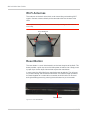
Wi-Fi Antennas
The antennas on the back of the Helix are for transmitting and receiving Wi-Fi
signals. Connect antennas directly to the connectors found at the back of the
Helix.
Note: Optimal antenna performance can be achieved by orienting the WiFi antennas
horizontally.
Wi-Fi Antennas
Figure 3-3: Wi-Fi Connection
Reset Button
The reset button is a small hole located in on the front faceplate of the Helix. This
button provides a quick way to turn the Helix power off and back on. Simply insert
a paper clip or similar object into the hole to press the reset button.
In some cases the Airlink Helix may need to be reset to defaults. This will reset
any custom settings and connection information. If the ACEmanager password
has been forgotten or is unable to be accessed, the Airlink Helix can be reset
during the bootup process by pressing the reset button for just 10 seconds.
Reset Button
Figure 3-4: Helix: Reset Button
12
2140847
Hardware Overview
Power Connector
Helix comes with a switching adapter. The power connector is located on the back
plate of the Helix.
Power adapter
Figure 3-5: Power Connector
SIM Slot
Note: This section applies to Helix with GSM technology only.
To insert the SIM in to the SIM slot, follow the instructions as below:
1. Carefully remove the SIM card from the card you received.
Figure 3-6: SIM card
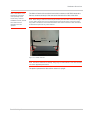
2. Gently press the SIM to click it into place.
Figure 3-7: Insert SIM
3. When the SIM card is fully inserted, it will lock into the holder with a click
sound.
Rev 3.0D May.10
13
AirLink Helix User Guide
Figure 3-8: Pushing SIM in to the SIM slot
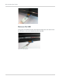
Remove the SIM
Firmly press on the SIM and it will unlock from the holder with a click sound. Once
the SIM ejects, use a pair of tweezers to pull out the SIM.
Figure 3-9: Removing SIM
14
2140847
4
4: USB Connection
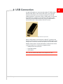
A single USB modem can be connected to Helix RT. USB modems
Compass 598 (Sprint) and Compass 895 (AT&T) are supported.
Only one cellular device, that is either the Helix RT or the USB
modem operates at a given time. When a USB modem is connected
to the Helix RT, it assumes all the functions of the internal radio
module to provide WWAN connectivity. Once the USB modem is
removed the internal radio module of Helix RT restarts.
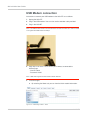
Figure 4-1: USB modems : Compass 895 and Compass 598
When a USB modem is connected to the Helix RT, it performs with
the other all the features as if it were the Helix RT. WAN failover, APN
configuration, and similar features now operate with the USB modem.
Multiple failover options include USB modem in WAN failover feature,
so that the software can automatically toggle between:
•
WAN port Ethernet connection
•
Embedded modem
•
USB modem.
Note: Only one external USB modem can be plugged in at a time.
Rev 3.0D May.10
15
AirLink Helix User Guide
USB Modem connection
Instructions to connect your USB modem to the Helix RT are as follows.
1. Unplug the Helix RT.
2. Plug in the USB modem. You can also use the extender cable provided.
3. Plug in the Helix RT.
Note: The USB modem needs to be inserted when the Helix is turned off, in order for Helix
to recognize the USB modem at startup.
4. Enter http://192.168.2.1:9191.htm on your browser, to connected to
ACEmanager.
· User ID: admin
· Password: 12345
Note: USB radio supports all other Helix software features.
5. In ACEmanager,
a. By selecting the About tab, you can view the Helix module information.
Figure 4-2: ACEmanager: Status - About
16
2140847
USB Connection
6. Check the LED lights on the USB modem, to check the status of the USB
connection.
Information for the USB modem connection is available on the Status tab in
ACEmanager. GSM users can configure their APN on the WAN/Cellular tab in
ACEmanager.
Rev 3.0D May.10
17
AirLink Helix User Guide
18
2140847
5
5: Configuring AirLink Helix
• ACEmanager
• Status
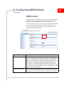
ACEmanager
ACEmanager is the free utility used to manage and configure the
AirLink Helix RT. After powering on the Helix, you can log on to
ACEmanager by :
•
Entering http://192.168.2.1:9191/index.htm in your browser.
The default login credentials are:
•
Login: admin
•
Password: 12345
To prevent others from changing the Helix settings, change the
ACEmanager password. See the Security topic in the “Configuring
Airlink Helix" for more information.
Status
All of the fields in the “Status” group have read-only parameters and
provide information about the Helix. Depending on the individual
settings and the onboard cellular module of the Helix, the actual
status pages may look different than the screenshots listed here. The
individual status sections give an accurate view of the current running
configuration of the Helix. Refer to the following sections for
information about the individual configuration options.
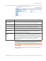
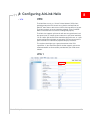
Home
The home section of the status tab has basic information about the
cellular network connection. Refer to the "WAN / Cellular" section for
information about configuring the cellular modem.
Figure 5-1: ACEmanager: Status - Home
Rev 3.0D May.10
19
AirLink Helix User Guide
Table 5-1: Status: Home
Command
Description
Backhaul mode
WAN backhaul mode : cellular, failover, passthrough.
Phone Number
This is the phone number that is programmed in to your device.
Current WAN IP
address
This can be the IP address of the cellular modem, if it is being used or the IP address of
WAN port if WAN Failover has switched to the Ethernet connection.
Network State
Not Connected or Connected. Current state of the cellular radio.
RSSI
Signal strength of the cellular signal. The lower the number, the better the signal strength.
The exact numbers vary between cellular carriers. However, -40dBm means Helix has a
significantly stronger coverage area than when it is -70dBm.
Network Operator
Indicates the network the modem is currently on.
Network Service Type
The type of service being used by the modem, for example EV-DO Rev A or HSPA.
ALEOS Software
Version
Software version of the ALEOS build.
Channel
The current active CDMA/GSM channel number.
Modem Name
Name of the modem.
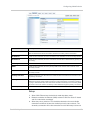
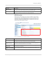
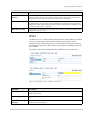
WAN/Cellular
WAN/cellular status indicates specific information about the cellular connection
including IP address and how much data has been used.
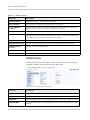
Figure 5-2: ACEmanager: Status - WAN/Cellular
Command
Description
Cellular IP Address
Cellular WAN IP Address.
Ethernet IP Address
Ethernet IP Address. This is present in WAN failover mode only.
WAN Link
WAN Link defaults to cellular. In WAN failover mode this can be either cellular or Ethernet.
ESN/EID/IMEA
The cellular radio module's unique identification number or electronic serial number (ESN
or IMEA).
20
2140847
Configuring AirLink Helix
Command
Description
Keepalive IP Address
The IP address that WAN keepalive uses to test cellular connectivity.
Keepalive Ping Time
The amount of time between keepalive pings in minutes.
0 is off and 255 is max.
Gateway
Gateway IP address of the local network.
DNS Server 1
First DNS IP addresses of cellular or Ethernet network.
DNS Server 2
Second DNS IP addresses of cellular or Ethernet.
Time in Use (Minutes)
Total time of continuous network connectivity on either cellular or Ethernet WAN. This timer
restarts when the connection is reset.
Traffic Over WAN
(KB)
Total amount of data sent and received during this session. This is reset when the
connection is reset.
Keepalive is an optional feature. If you frequently pass data with your modem, you
most likely do not need to have Keepalive enabled. When using Keepalive, be
aware that a ping moves approximately 66 bytes of data over the network and is
billable by Carrier. The following *IPPING settings will incur approximate monthly
data usage in addition to any other data usage:
*IPPING
Estimated Usage
15 minutes
400k / month
30 minutes
200k / month
60 minutes
100k / month
120 minutes
50k / month
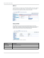
LAN/WiFi
This is the status of the local network. It lists information about the network and
connected clients. If the Helix has Wi-Fi, Wi-Fi status information will be shown
here.
Rev 3.0D May.10
21
AirLink Helix User Guide
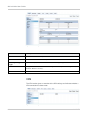
Figure 5-3: ACEmanager: Status - LAN/WiFi
Command
Description
Ethernet Port 1
Address / status of the LAN port.
Ethernet Port 2
Address / status of the WAN / LAN port.
Security Encryption
type
Options are Open, WEP, or WPA. Shows the Wi-Fi encryption type.
WiFi Mode
The type of Wi-Fi network. If the Helix is configured exclusively as an 802.11g network, this
will show "Mixed" or "G-Only".
Connected Clients
Number of connected clients.
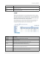
VPN
The VPN section gives an overview of the VPN settings and indicates whether a
VPN connection has been made.
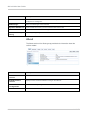
Figure 5-4: ACEmanager: Status - VPN
22
2140847
Configuring AirLink Helix
Command
Description
VPN 1
Disabled, Enabled, Connected. The status of the IPSec VPN client.
VPN 2
Disabled, Enabled, Connected. The status of the GRE client.
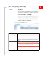
Security
The security section provides an overview of the security settings on the Helix.
Figure 5-5: ACEmanager: Status - Security
Command
Description
DMZ
Disabled or Enabled. Indicates whether a DMZ is in use.
Port Forwarding
Shows the status of any port forwarding settings.
0 is OFF;1 is ON
Port Filtering
Outbound
Enabled or disabled. Show status of outbound port filtering.
Services
This section shows the ACEnet status.
Figure 5-6: ACEmanager: Status - Services
Rev 3.0D May.10
23
AirLink Helix User Guide
Command
Description
ACEnet
ACEnet status. If an ACEnet account has been setup, the status will change from "Not
Configured" to "Configured".
ACEmanager
Status of ACEmanager access selected.
Dynamic DNS Service
Dynamic DNS Service that you have selected under Services tab.
Full Domain Name
Dynamic DNS full domain name configured.
SNMP Community
String
Community String configured for SNMP.
About
The About section of the Status group provides basic information about the
cellular modem.
Figure 5-7: ACEmanager: Status - About
Command
Description
Radio Firmware
Version
Firmware version in the radio module.
ALEOS Software
Version
Displays version of ALEOS software running on the Helix RT.
Modem Hardware
Configuration
Versions of internally configured hardware.
MSCI Version
Version of MSCI
24
2140847
6
6: Configuring WAN/Cellular
• WAN/Cellular
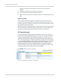
WAN/Cellular
The WAN/Cellular section allows changes to the cellular connection
and main operating mode of the Helix. Some settings may appear
differently and are dependent on cellular carrier settings.
The default mode is "Cellular". This uses the onboard cellular module
as primary means of connection and enables all other onboard
features. Custom connection settings can be included if they are
supported by the cellular module.
Figure 6-1: ACEmanager: WAN/Cellular
Command
Description
Backhaul Mode
Cellular, WAN failover, IP Passthrough. These are the three operating modes
of the Helix. Cellular mode is the default mode and in this mode the Helix
operates as cellular modem with LAN routing capabilities. WAN failover mode
uses either the cellular modem or an Ethernet WAN link (DSL, cable, office
LAN) to connect to the Internet. The Helix will then manage and switch
between the two connections based on their availability. IP Passthrough
mode will pass the cellular WAN IP address directly through to any client
connected to port 2 of the Helix. This is used in some VPN scenarios or when
a device requires an external IP address. Devices connected to port 1 or WiFi will still receive DHCP addressing.
Network Credentials
Default or Custom. Default settings are the default cellular data connection
settings in the United States. Selecting Custom settings will show another set
of fields allowing you to use custom settings for specific carrier information.
Rev 3.0D May.10
25
AirLink Helix User Guide
Command
Description
Set APN (GSM only)
APN or Access Point Name is specific to GSM networks. Custom access
points can be used to create VPN connections or to provide specific routing
functionality. Contact your cellular carrier for more information about how
these work.
Network User ID
Enter the user name needed the authenticate on your APN. This is provided
by your cellular operator.
Network Password
This setting shows up on Helix boxes with GSM and CDMA technology. Fill in
the password that accompanies the custom connection information.
Keepalive IP Address
The IP address that the Helix will ping to determine if there is internet
connectivity. By default, this is set to a Sierra Wireless server, but this can be
changed. If the Helix is setup for WAN failover, or any custom cellular settings
(ie Datalink or custom APN), make sure this IP address is accessible.
Keepalive Ping Time
This is the amount of time between keep-alive pings in seconds. This setting
prevents the cellular modem from going into a low power, or hibernation
mode by regularly sending out ICMP pings. By default, this is configured to
3600 seconds or an hour. If the ping fails, the Helix will send an additional
three pings to the specified address. If those pings fail, the Helix will restart
the cellular connection automatically.
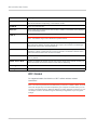
WAN Failover
WAN Failover allows the Helix to intelligently manage two Internet connections,
switching from one to the other as needed. After enabling this mode, Helix will
continually test the primary Internet connection. If tests fail, Helix will
automatically switch to the secondary connection while continuing to test the
primary connection and switch back to the primary connection when connectivity
is returned.
26
2140847
Configuring WAN/Cellular
Figure 6-2: ACEmanager: WAN/Cellular - WAN Failover
Command
Description
Ethernet WAN IP
Static or DHCP. If DHCP is selected, no other IP related information needs to be entered. If
Static is selected enter the IP information about the secondary Internet connection.
IP Address
If Static mode is selected, this is the IP address of the Helix Box on the secondary network.
IP Netmask
If Static mode is selected, this is the netmask of the Helix Box in WAN Failover (primary or
secondary).
Gateway IP
If Static mode is selected, this is the gateway IP address of the that the Helix Box.
DNS 1
If Static mode is selected, this is the primary DNS server that the Helix connects on the
secondary network.
DNS 2
If Static mode is selected, this is the secondary DNS server that the Helix connects on the
secondary network.
Primary Interface
Cellular or Ethernet. This determines the cellular module or the Ethernet connection to be
the primary connection.
Primary Route IP
This is the IP address that Helix continually tests connectivity with. Helix will ping this
address through the primary WAN connection to ensure the primary connection is working.
If a ping to this address fails, Helix will rollover all WAN connectivity to the secondary WAN
connection until it can resume connectivity to this address through the primary connection.
Interval (Secs)
Determines how often the Primary Route IP is tested.
Setup
1. Select WAN Failover from the backhaul mode drop-down menu.
2. Determine whether the Ethernet (WAN) network is DHCP or Static IP based
and fill in information accordingly.
3. Select the primary interface. This should be selected as the most reliable
connection and will be the one that the Helix primarily uses and tests. The
secondary connection will be the connection that the Helix keeps active and
Rev 3.0D May.10
27
AirLink Helix User Guide
switches to if the primary connection fails. Default primary interface is
Ethernet.
4. If needed, change the Primary Route IP and interval.
5. Click on Apply and reboot the box when prompted.
6. Plug in the Ethernet cable for the WAN connection in to WAN/LAN port of the
Helix.
How it works
When enabled, Helix will ping the Primary Route IP at the interval you have
configured. If one of these pings fails, Helix will immediately send another short
series of pings to that IP address. If these pings also fail, Helix will switch to using
the secondary Internet connection.
While the secondary Internet connection is being used, Helix will continue to ping
the Primary Route IP to determine when the connection is restored. When the
connection is restored, Helix will switch back to the primary connection.
IP Passthrough
IP Passthrough mode will pass the cellular WAN IP address directly through to
any client connected to WWAN/LAN port on the Helix. This may be necessary for
some VPN configurations or other enterprise applications. The Helix can also
continue to provide LAN IP addresses to clients connected through LAN port (or
Wi-Fi with supported devices). However WAN Failover, DMZ, and Port Forwarding
are not available and ACEmanager cannot be reached through port 1. Any client
connected to WWAN/LAN port must be setup with a static IP address and a
gateway address that matches the WWANIP address and gateway address. IP
passthrough works best when the cellular module is setup by the cellular carrier
to receive a public static IP address on the carrier network.
Figure 6-3: ACEmanager: WAN/Cellular - IP Passthrough
28
2140847
7
7: Configuring LAN/WiFi
• LAN/WiFi
LAN/WiFi
The LAN/WiFi section displays VLAN configuration parameters, in
ACEmanager.
VLAN stands for virtual LAN. VLANSs help structure the network
growth of companies. A VLAN typically has a cluster of hosts that are
together in a broadcast domain and not based on their physical
location. A difference between VLAN and LAN is that a VLAN allows
devices to be grouped together even when the devices are not
located on the same network switch.
The VLAN implementation with a Helix is more of a VLAN support.
i.e. if there is a switch behind the Helix that supports VLAN, Helix will
forward the packet to the appropriate VLAN segment.
ACEmanager allows the users to reconfigure their network instead of
relocating devices.
Addressing/VLAN
This section indicates the status and allows you to change the IP
settings of the local network.
Note: Changing settings in this area will require you to reconnect to
ACEmanager after saving any changes.
Figure 7-1: ACEmanager: LAN/WiFi - Addressing
Rev 3.0D May.10
29
AirLink Helix User Guide
Command
Description
Interface
There is a Default interface (Bridged Ethernet and WiFi) and three Ethernet VLANs and
WiFi WLAN interfaces respectively, in the interface column.
VLAN ID
Enter your VLAN IDs here.
Ethernet
Three virtual ethernet interfaces for three VLANs in addition to the default LAN is displayed
on the ACEmanager screen.
WiFi 2, WiFi 3 and
WiFi 4
WiFi 2, 3, and 4 have to be configured independently.
Note: The address range of each WLAN is a separate subnet.
Device IP
IP address of the Helix. By default this is set to 192.168.2.1. Changing this will affect the
start and end IP address. Changing this will also require a reconnection to ACEmanager
and physical reconnection of the LAN Ethernet.
Subnet mask
The subnet mask indicates how large the IP address pool will be. Changing this will limit or
expand the number of clients that can connect to the Helix. The default is 255.255.255.0
and means that 254 clients can connect to the Helix.
Access Internet
Choose access to internet, “Yes” or “No” from scroll down option for Ethernet. WiFi is set to
“Yes” by default.
DHCP Server Mode
Enabled or Disabled. By default, the Helix has a DHCP server that is enabled. Disabling the
server will require all connected clients to have static IP addressing.
Starting IP
DHCP pool start IP address.
Ending IP
The Ending IP for the Ethernet Interface.
WiFi Global
On supported models, the Helix has a Wi-Fi radio for wireless network
connections.
Note: You can lock yourself out of the Helix when you first turn on WEP or WPA. You must
then enter the right key in the format required by your computer or device before you can
connect to the Helix with Wi-Fi. WEP and WPA do not affect Ethernet connections, so you
can always connect to the Helix through an Ethernet port regardless of your encryption
settings.
30
2140847
Configuring LAN/WiFi
Figure 7-2: ACEmanager: LAN/WiFi - WIFI
Command
Description
Enable Wireless
Access Point
WI-Fi on or Wi-fi off. Allows you to disable or enable the Wi-Fi access point. If you are using
the Helix in an environment where security or safety require that you disable Wi-Fi, you can
turn Wi-Fi off here. The WAN and Ethernet LAN connections will remain active.
SSID/Network Name
The default network name is 'helix'.
Hide SSID
Hide or Show. This determines whether the SSID will be broadcasted by the Helix. Hiding
the SSID will not prevent people from connecting to the box if the signal is open.
Wireless Mode
G-only or Mixed. By default, the Mixed mode option provides the greatest compatibility with
802.11b and 802.11g devices. To create a pure 802.11g network, select the G-Only mode.
Wi-Fi Channel
1-11. The Wi-Fi access point on the Helix can use any of 11 channels. If other Wi-Fi
networks are in range and operating on nearby channels, you may be able to avoid
interference by changing to a different Wi-Fi channel.
Security Encryption
type
Open, WEP, WPA. The Helix box supports Wired Equivalent Privacy (WEP) and Wi-Fi
Protected Access/802.11i (WPA and WPA2 Personal and Enterprise). Both protocols will
restrict access to the Helix box and protect data transmitted between the clients and the
device. WPA provides the highest level of security if all of the LAN devices on your network
support this protocol. WPA Enterprise is the follow on wireless security method to WPA that
provides stronger data protection for multiple users and large managed networks. It
prevents unauthorized network access by verifying network users through an
authentication server.
Note: WiFi Default has Shared WEP as an option in the Security Encryption Type field,
while WiFi 2, WiFi 3, and WiFi 4 does not have Shared WEP as an option.
Shared WEP
WEP or Wireless Encryption Protocol is the least secure, but most supported
encryption method.
Rev 3.0D May.10
31
AirLink Helix User Guide
Figure 7-3: ACEmanager: WIFI - Shared WEP
Command
Description
Key Length
64 bit, 128 bit, Custom. WEP is available with shorter 64 bit keys or longer 128 bit keys.
While 128 bit encryption provides a higher level of security, some computers and Wi-Fi
clients only support 64 bit encryption. Use a key length that is compatible with all of the
wireless clients on your network.
WEP Passphrase
The default passphrase is 'HelixWEP'. You can enter your own private WEP passphrase to
generate a hex (hexadecimal) key. Treat the passphrase like a password and select one
that is difficult for others to guess. After you enter a new passphrase, click the Apply button
to make the change effective. When logging into Wi-Fi from your computer, enter the hex
key, not the passphrase. Most WEP connections only use the hexadecimal format. The
passphrase is simply used as an easy way for you to create a hex key. You can configure
your own hex key rather than generating one with a passphrase by selecting the 'Custom
Key' option from the drop-down menu. Make sure your hex key only includes 10 or 26 valid
hex digits, created through pairs of characters of 0-9 and/or a-f, with each pair separated by
a colon. For example, 80:3a:c9:95:b8.
WPA/WPA2 Personal
WPA/WPA2 Personal is a higher level of encryption than WEP, requiring a pre
shared passphrase be known before being able to connect to a network.
Figure 7-4: ACEmanager: WiFi - WPA/WPA2 Personal
32
2140847
Configuring LAN/WiFi
Command
Description
WiFi Encryption
TKIP or AES. Defines what encryption scheme to use under WPA. Options are Temporal
Key Integrity Protocol (TKIP) and Advanced Encryption Standard (AES).
WPA Passphrase
By default this is 'HelixWPAPassphrase'. You can change this to another phrase with
alphanumeric characters and symbols when creating a passphrase.
WPA Enterprise
WPA Enterprise adds another layer of security to WPA by requiring clients
authenticate with a server before being able to access the network. Clients
connecting to the Helix when WPA Enterprise is enabled will need to have
certificates installed from the RADIUS server, allowing them access to the
network before being allowed to connect.
Figure 7-5: ACEmanager: WiFi - WPA/WPA 2 Enterprise
Command
Description
WiFi Encryption
TKIP or AES. Defines what encryption scheme to use under WPA. Options are Temporal
Key Integrity Protocol (TKIP) and Advanced Encryption Standard (AES).
Primary or Secondary
Radius Server IP
This is the IP address of your enterprise RADIUS server. These servers must be accessible
ALL the time or clients will not be able to connect via Wi-Fi. The secondary server is
optional and used when the primary server is not available.
Secondary Radius
Server Port
This is the port number of your enterprise RADIUS server. The secondary port is used
when the primary is unavailable.
Primary or Secondary
Radius Server Secret
This is the shared secret key used to secure communications with the RADIUS server.
Rev 3.0D May.10
33
AirLink Helix User Guide
WiFi 2
The WiFi interface can support up to 4 WiFi LANs (WLAN), each with a separate
SSID, and separate encryption settings. Global settings apply to all WLANS.
Each WLAN may be routed to the Internet under user control.
Figure 7-6: ACEmanager: LAN/WiFi - WiFi 2
Global DNS
Global DNS allows you to override the default DNS settings of the cellular
modem. This is used when custom cellular network settings (such as DataLink or
custom APNs) are used on the cellular modem. Some carriers will block this
setting. Check with your cellular carrier for more information.
Figure 7-7: ACEmanager: LAN/WiFi - Global DNS
Command
Description
Primary DNS
Primary Global DNS Address.
Secondary DNS
Secondary Global DNS Address.
DNS Override
Disabled or Enabled. By default this is set to Disabled.
34
2140847
Configuring LAN/WiFi
Command
Description
Alternate Primary
DNS
Alternate primary DNS address. This is optional. If the primary DNS is unavailable, this
DNS address will be used.
Alternate Secondary
DNS
Alternate secondary DNS address. This is optional. If the secondary DNS is unavailable,
this DNS address will be used.
VRRP
VRRP allows multiple routers to act as the default gateway router for a subnet
which reduces the possibility of a single point of failure. This is accomplished by
advertising a single virtual router to connected hosts. The physical router that is
currently handling traffic for the virtual router is designated as the master router.
Routers which are not handling traffic are backup routers.
This switchover occurs in 3 to 10 seconds. While IPsec client connections are
disconnected during this transition, users need only to reconnect without
changing the destination address of their connection profile.
Figure 7-8: ACEmanager: LAN/WiFi - VRRP
Command
Description
Interface
Interface displays one default VLAN and 3 VLAN IDs.
VLAN ID
Displays your VLAN ID.
Group ID
Enter VRRP Group ID.
VRRP routers in the master and slave have the same Group ID.
Priority
VRRP decides whether the device is master or slave.
Greater value of priority indicates that the device is master.
Virtual IP
If a Helix is configured with VRRP then the host connected to the Helix will display the Virtual
IP.
Virtual IP will become the VRRP routers device IP.
Mode
Displays if the Helix is Master or Back-up.
The Priority number determines the master or back-up status.
Interval
VRRP advertisement interval. Default is 1 second.
Rev 3.0D May.10
35
AirLink Helix User Guide
36
2140847
8
8: Configuring AirLink Helix
• VPN
VPN
The Helix Box can act as a Virtual Private Network (VPN) client,
providing enterprise VPN access to any device connected to the
Helix RT even when a device has no VPN client capability on its own.
The Helix supports up to two tunneling protocols, IPsec and GRE.
Both can be used at the same time if configured properly.
The Helix also supports split tunnels with one encrypted tunnel and
one open tunnel. A sample server subnet for a split tunnel would be
172.16.1.0/24. Split tunnel VPNs should be setup with care, as a split
tunnel configuration with both an enterprise VPN and access to the
public Internet can inadvertently expose company resources.
This section should give you a general overview of the VPN
capabilities. If you would like specific solution support, refer to the
recommendations and instructions provided with your VPN server
solution.
VPN 1
Figure 8-1: ACEmanager:VPN1 - IPSec Tunnel
Rev 3.0D May.10
37
AirLink Helix User Guide
Command
Description
VPN 1 Type
Tunnel Disabled or IPsec tunnel. Use this option to enable or disable the VPN tunnel. If
custom settings are used, they will be saved and the tunnel can be disabled and reenabled without needing to reenter any of the settings. The IPsec VPN employs the IKE
(Internet Key Exchange) protocol to set up a SecurityAssociation (SA) between the Helix
and a Cisco (or Cisco compatible) enterprise VPN server. IPSec consists of two phases to
setup an SA between peer VPNs. Phase 1 creates a secure channel between the Helix
VPN and the enterprise VPN, thereby enabling IKE exchanges. Phase 2 sets up the IPSec
SA that is used to securely transmit enterprise data. For a successful configuration, all
settings for the VPN tunnel must be identical between the Helix VPN and the enterprise
VPN server.
VPN1 Status
Disabled, Not Connected, or Connected. This indicates the current status of the VPN
connection. Use this as part of troubleshooting a VPN connection.
SNTP Server Address
The Simple Network Time Protocol Server (SNTP) ensures the clock on the Helix VPN is
synchronized to standard time. The default NTP server is pool.ntp.org. You can specify any
preferred NTP server. Both the VPN server and client must use the same SNTP address.
VPN Gateway
Address
The IP address of the server that this client connects to. This IP address must be open to
connections from the Helix Box.
Remote Subnet (IP
Addr Mask)
The default configuration is 0.0.0.0/0 which will direct all traffic over the GRE tunnel.
Pre-shared Key 1
Pre-shared Key (PSK) used to initiate the VPN tunnel.
My Identity
If these fields are left blank, My Identity will default to the WAN IP address assigned by the
carrier and Peer Identity will default to the VPN Server IP. For a fully qualified domain name
(FQDN), these values should be preceded by an ‘@’character (@www.domain.com). For
user-FQDN, these values should include a username ([email protected])
Peer Identity
Required in some configurations to identify the client or peer side of a VPN connection.
This defaults to the VPN server IP address.
Negotiation Mode
Main Mode or Aggressive. To operate the onboard VPN under Aggressive mode, enable
this configuration. By default the Helix operates under Main Mode. Aggressive mode offers
increased performance at the expense of security.
IKE Encryption
Algorithm
DES, 3DES, or AES. Determines the type and length of encryption key used to encrypt/
decrypt ESP (Encapsulating Security Payload) packets. 3DES supports 168-bit encryption.
AES (Advanced Encryption Standard) is supports 128 bit encryption.
IKE Authentication
Algorithm
SHA1 or MD5. Can be configured with MD5 or SHA1. MD5 is an algorithm that produces a
128-bit digest for authentication. SHA1 is a more secure algorithm that produces a 160-bit
digest.
IPSec Encryption
Algorithm
DES, 3DES, or AES. Determines the type and length of encryption key used to encrypt/
decrypt ESP (Encapsulating Security Payload) packets. 3DES supports 168-bit encryption.
AES (Advanced Encryption Standard) supports 128 bit encryption.
IPSec Authentication
Algorithm
SHA1 or MD5. Can be configured with MD5 or SHA1. MD5 is an algorithm that produces a
128-bit digest for authentication. SHA1 is a more secure algorithm that produces a 160-bit
digest.
IKE SA Life Time
180 to 86400. Determines how long the VPN tunnel is active in seconds. The default value
is 28,800 seconds, or 8 hours
38
2140847
Configuring AirLink Helix
Command
Description
Perfect Forward
Secrecy
Yes or No. Provides additional security through a DH shared secret value. When this
feature is enabled, one key cannot be derived from another. This ensures previous and
subsequent encryption keys are secure even if one key is compromised.
IPSec Key Group
DH1, DH2, or DH5. Determines how the Helix VPN creates an SA with the VPN server. The
DH (Diffie-Hellman) key exchange protocol establishes pre-shared keys during the phase 1
authentication. Helix supports three prime key lengths, including Group 1 (768 bits), Group
2 (1,024 bits), and Group 5 (1,536 bits).
IPSec SA Life Time
180 to 86400. Determines how long the VPN tunnel is active in seconds. The default value
is 28,800 seconds, or 8 hours.
VPN 2
The Helix can act as a Generic Routing Encapsulation (GRE) endpoint, providing
a means to encapsulate a wide variety of network layer packets inside IP
tunneling packets. With this feature you can reconfigure IP architectures without
worrying about connectivity. GRE creates a point-to-point link between routers on
an IP network.
The VPN 2 section allows configuration of the GRE tunnel on the Helix box.
Figure 8-2: ACEmanager: VPN 2 - VPN/IPSec
Figure 8-3: ACEmanager: VPN 2 - VPN/IPSec - GRE Tunnel
Command
Description
VPN 2 Type
Tunnel Disabled or GRE Tunnel. Enabling the GRE Tunnel will expose other options for
configuring the tunnel.
VPN Status
Disabled, Connected or Not Connected. Indicates the status of the GRE tunnel on the Helix
box.
VPN Gateway
Address
The IP address of the device that this client connects to. This IP address must be open to
connections from the Helix Box.
Rev 3.0D May.10
39
AirLink Helix User Guide
Command
Description
Remote (IP Addmask)
The default configuration is 0.0.0.0/0 which will direct all traffic over the GRE tunnel.
GRE TTL
GRE time to live (TTL) value is the upper bound on the time that a GRE packet can exist in
a network. In practice, the TTL field is reduced by one on every router hop. This number is
in router hops not in seconds.
40
2140847
9
9: Configuring Security
• Security
Security
Most security features can be configured on the Security page. It is
recommended you change the default password for ACEmanager.
Port Forwarding and DMZ
To add a rule, fill in the outside port (ie, 8080), the protocol (TCP or
UDP), the host (or internal) IP, and the private port (the port on the
inside of the network). Some cellular carriers restrict port access.
Check with your cellular carrier if you have problems setting this up.
To add more rules, click on the Add More button. To remove a rule,
click on the 'X' button that is next to the rule.
Figure 9-1: ACEmanager: Security - Port Forwarding
Command
Description
Port Forwarding
Enabed
Disabled or Enabled. Disables or Enables port forwarding rules.
DMZ IP
IP address of a DMZ. The Helix allows a single client to connect to the
Internet through a demilitarized zone (DMZ). The DMZ is particularly useful
for certain services like VPN, NetMeeting, and streaming video that may not
work well with a NAT router. DMZ host is unavailable if IP passthrough is
enabled.
DMZ Enabled
OFF or ON. Enables or disables the DMZ on the Helix. The Helix allows a
single client to connect to the Internet through a demilitarized zone (DMZ).
Note: All security features are inactive if DMZ is enabled.
Note: Because DMZ traffic does not pass through the NAT router, the DMZ
host is fully exposed to the Internet without the protection of the Helix firewall.
If the DMZ is used, this can present a security risk to the DMZ host client.
Rev 3.0D May.10
41
AirLink Helix User Guide
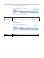
Port Filtering - Outbound
Figure 9-2: ACEmanager: Security - Port Filtering-outbound
Command
Port Filtering Outbound
Description
Independent of the IP filtering, this mode can be enabled to block ports specified. When
enabled, all ports not matching the rule will be blocked depending on the mode.
MAC Filtering
Figure 9-3: ACEmanager: Security - MAC Filtering
Command
MAC Filtering
42
Description
MAC Filtering allows communication to Helix through the listed MAC address(s) only.
2140847
10
10: Configuring Services
• Services
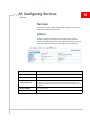
Services
The services sections allows configuration of external services that
extend the functionality of the Helix.
ACEnet
ACEnet is a remote management service that can be used to
remotely configure and view the status of Helix boxes and other
ALEOS compatible devices. For more information about this service,
go to: http://www.sierrawireless.com/Product/airlink/acenet.aspx
Figure 10-1: ACEmanager: Services - ACEnet
Command
Description
ACEnet Management
Enabled or Disabled
Service URL
ACEnet URL
Device Initiated
Interval (Minutes)
Variable. This determines how often the Helix checks for software updates
and settings changes from ACEnet. ACEnet can also query the Helix at a
regular interval if settings allow. Refer to the ACEnet documentation for more
information.
Account Name
Your account name
Status
Connected or Not Connected.
Rev 3.0D May.10
43
AirLink Helix User Guide
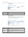
ACEmanager
Figure 10-2: ACEmanager: Services - ACEmanager
Command
Description
Enable ACEmanager
Enable ACEmanager on Tethered Host and Wifi or ALL (includes OTA).
ACEmanager Port
Port for accessing ACEmanager is 9191.
Dynamic DNS
Dynamic DNS allows a Helix Box WAN IP address to be published to a third-party
service. Be aware of the Dynamic DNS abuse policy when setting this up to
ensure that the Helix is not blocked from the service.
Figure 10-3: ACEmanager: Services - Dynamic DNS
Command
Description
Dynamic DNS Update
The Dynamic DNS update can be updated periodically (Periodic Update), at which point ot
will use interval. The other option is “Only on Change”, which will send a dynamic DNS
update on every reoory if the IP of the network changes.
Service
dyndns.org, noip.org, ods.org, regfish.com, or tzo.com. Select the dynamic DNS provider
that you have an account with.
Login
Login for Dynamic DNS.
44
2140847
Configuring Services
Command
Description
Password
Password for Dynamic DNS provider.
Interval
Enter Interval in Sec. Be careful when entering this information to match the
recommendations from your Dynamic DNS provider.
Full Domain Name
Full domain name provided by your Dynamic DNS provider. An example is, helixrt.noip.org
for instance.
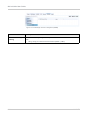
Landing Page
When Landing page is configured, an internet connection is blocked until the
landing page is viewed from the web browser.
Figure 10-4: ACEmanager: Services - Landing Page
Command
Description
Enable Landing Page
Select “Enable” to enable the landing page.
Landing Page URL
URL of the landing page viewed. This can be on the remote location or on connected
computer.
Note: WiFi 2, 3 and 4 are not affected by landing page.
Note: When the device first receives the nework IP and the landing page cannot be
reached, you could get an error indicating Internet access is unavailable.
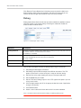
Management (“SNMP)
The Simple Network Management Protocol (SNMP) was designed to allow
remote management and monitoring of a variety of devices from a central
location. The SNMP management system is generally composed of agents (such
as your Helix device) and a Network Management Station (NMS) which monitors
all the agents on a specific network. Using the management information base
(MIB), an NMS can include reporting, network topology mapping, tools to allow
traffic monitoring and trend analysis, and device monitoring.
Rev 3.0D May.10
45
AirLink Helix User Guide
Figure 10-5: ACEmanager: Services - Management (SNMP)
Command
SNMP community
String
46
Description
The SNMP Community String acts like a password to limit access to the device’s SNMP
data.
• string = string of no more than 20 characters (default = public).
2140847
11
11: Configuring Admin
• Admin
Admin
The admin section of the Helix allows the box to be reset to defaults,
the password to be changed, and debug mode.
Figure 11-1: ACEmanager: Service - Admin
It is highly recommended to change the default password of the
Helix.
To change the default password,
1. Enter the user name (admin).
2. Enter the old password.
3. Enter the new password twice.
4. Click on Change Password
You will be prompted to restart the Helix. When the box has restarted,
reconnect to ACEmanager and you will be prompted to enter the new
password.
Defaults
This will reset all settings (passwords, LAN and WAN configuration,
security settings, etc.) to the original factory settings.
Figure 11-2: ACEmanager: Admin - Default
Rev 3.0D May.10
47
AirLink Helix User Guide
Click Reset to Factory Defaults to initiate the process to reset the Helix to its
default settings. After clicking on the button, the Helix will reset and you can
connect to ACEmanager with the default username and password.
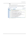
Debug
Debug mode allows direct control over the cellular module for additional control,
technical support, and custom settings. Enabling this mode will disable the
onboard cellular module control.
Figure 11-3: ACEmanager: Admin - Debug
Command
Description
Debug Enabled
Disabled or Enabled. Disabled is the default state. Enabling this option will pass control of
the cellular module to an external device for control.
"0">Disabled;"1">Enabled
Debug Output
TCP or DB9. This option selects the output of the debug control. TCP will send the output
over TCP and DB9 will send the output over the serial port.
"0">TCP;"1">DB9
BAUD Rate
Speed of the port.
TCP Port
The port to connect to, is specified when using the TCP debug mode.
Here is how to configure the Helix for debug mode using AT commands:
1. Set Debug Enabled option to Enabled.
2. Set Debug Output to DB9 for output to the DB9 on the device. The TCP
option can be used if a virtual serial port is setup on the host device.
3. Set Dev Port to the radio module port that pass through mode to AT.
4. Set the BAUD Rate to 115200
5. Set the TCP Port if Debug Output is set to TCP. Ignore this option if you are
using a serial cable
6. Click the Apply button and OK in the popup window that reads: “Applied the
changes successfully.”
7. Click Reboot button.
8. Attach a serial cable to the Helix device after it has been rebooted.
Note: The Helix must be rebooted when enabling or disabling debug mode.
48
2140847
Configuring Admin
Log
The log file is a system log of the helix unit.
Log 0 is the current data and Log 1 to 5 is the archived data. The Refresh tab will
refresh the display with current data. Clear tave will clear the log displayed.
Figure 11-4: ACEmanager: Admin - Log
Rev 3.0D May.10
49
AirLink Helix User Guide
50
2140847
12
12: Technical Specifications
•
•
•
•
•
•
WAN
LAN
Routing
Administration
Hardware
Physical
WAN
•
WAN fail-over of landline backhaul (DSL, cable, etc.)
•
WAN Alive maintains persistent cellular connection
•
Dynamic DNS client compatible with third-party DDNS services
LAN
•
Ethernet 10/100 megabit, 2 ports
•
Configurable LAN IP address
•
MAC filtering
•
Configurable DHCP server
•
Wi-Fi 802.11b/g
•
WPA and WPA2 Personal and Enterprise
•
WEP (64 or 128 bit)
Routing
•
NAT
•
WWAN IP passthrough
•
Static or DHCP IP address assignment
•
Custom APN for GSM networks
•
Port Forwarding
•
Outbound port restrictions
•
DMZ host
•
On-board VPN
Administration
Rev 3.0D May.10
•
ACEmanager, device config
•
Remote management option with ACEnet
•
Signal strength meter via ACEmanager
•
Upgradeable firmware
51
AirLink Helix User Guide
Hardware
•
FCC CFR47 PART 15 SUBPART C (FCC) compliant
· MC5727 id is N7N-MC5725
· MC8790 id is N7NMC8790
· WLM54G WiFi PCI card id MK8CPX-05-WLM54G.
•
Power, Status, Activity LEDs
•
Outlet Power adapter (12VDC, 1.5 amp)
Physical
52
•
Compact, rugged case
•
Dimensions: 6.25"x1.3875"x7.0625" (case, not including antenna)
•
Weight: 2.25 pounds
•
Operating temperature: 0°C to 50° C
•
Storage Temperature: -10C to +80C
2140847
13
13: Regulatory Information
Federal Communications Commission
Notice (FCC United States)
Electronic devices, including computers and wireless modems,
generate RF energy incidental to their intended function and are
therefore subject to FCC rules and regulations.
This equipment has been tested to, and found to be within the
acceptable limits for a Class A digital device, pursuant to part 15 of
the FCC Rules.
This equipment generates radio frequency energy and is designed
for use in accordance with the manufacturer's user manual. However,
there is no guarantee that interference will not occur in any particular
installation.
If this equipment causes harmful interference to radio or television
reception, which can be determined by turning the equipment off and
on, you are encouraged to try to correct the interference by one or
more of the following measures:
•
Reorient or relocate the receiving antenna
•
Increase the separation between the equipment and the receiver
•
Connect the equipment into an outlet on a circuit different from
that to which the receiver is connected
•
Consult the dealer or an experienced radio/television technician
for help
•
This device complies with Part 15 of the Federal Communications
Commission (FCC) Rules. Operation is subject to the following
two conditions:
1. This device may not cause harmful interference.
2. This device must accept any interference received, including
interference that may cause undesired operation.
Warning: Changes or modifications to this device not expressly approved
by Sierra Wireless could void the user's authority to operate this equipment.
Industry Canada
This Class A digital apparatus meets all requirements of the
Canadian Interference Causing Equipment Regulations. Operation is
subject to the following two conditions:
1. this device may not cause harmful interference, and
2. this device must accept any interference received, including interference that may cause undesired operation.
Rev 3.0D May.10
53
AirLink Helix User Guide
Cet appareillage numérique de la classe B répond à toutes les exigences de
l'interférence canadienne causant des règlements d'équipement. L'opération est
sujette aux deux conditions suivantes:
1. ce dispositif peut ne pas causer l'interférence nocive, et
2. ce dispositif doit accepter n'importe quelle interférence reçue, y compris
l'interférence qui peut causer l'opération peu désirée.
Antenna Considerations
Although the antenna model(s) used with these devices meet(s) the Industry
Canada Radio Frequency requirements, it is possible that the future customers
may swap them for different ones without network provider's knowledge and
approval. Such customers must be made aware of, and follow, the Radio
Frequency requirements applied in this Technical Approval:
•
RSS-102 "Radio Frequency Exposure Compliance of Radiocommunication
Apparatus (All Frequency Bands)"
•
RSS-129 "800 Mhz Dual-Mode CDMA Cellular Telephones"
•
RSS-132e "Cellular Telephones Employing New Technologies Operating in
the Bands 824-849 Mhz and 869-894 Mhz"
•
RSS-133 r1 "2 GHz Personal Communications Services"
RF Exposure
In accordance with FCC/IC requirements of human exposure to radiofrequency
fields, the radiating element shall be installed such that a minimum separation
distance of 20cm should be maintained from the antenna and the user's body .
Warning: This product is only to be installed by qualified personnel!
To comply with FCC/IC regulations limiting both maximum RF output power and
human exposure to RF radiation, the maximum antenna gain must not exceed 5
dBi in the Cellular band and 4 dBi in the PCS band.
EU
Note: At least 20 cm
separation distance
between the antenna and
the user's body must be
maintained at all times.
54
Sierra Wireless hereby declares that the Product Name devices conform to all the
essential requirements of Directive 1999/5/EC.
Products are marked with a CE and notified body number as shown here:
2140847
Regulatory Information
The Declaration of Conformity made under Directive 1999/5/EC is available for
viewing at the following location in the EU community.
Sierra Wireless
39677 Eureka Drive
Newark, CA
USA
94560
The device is a Class A device for use in commercial environment.
WEEE Notice
If you purchased Product Name in Europe, please return it to your dealer or
supplier at the end of its life. WEEE products may be recognised by their wheeled
bin label on the product label.
Rev 3.0D May.10
55
AirLink Helix User Guide
56
2140847