1
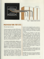
SYSTEM 1
REPEAT
AS
+
FOR
WIRI NG
SYSTEM
1
COM.
RIGHT
LEFT
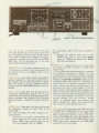
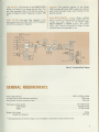
Figure1. Loudspeaker System
Connections
PREPARATION
FORUSE
Rear panel Signal Connection
All signal connections to the Model 1060 should be
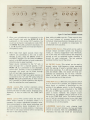
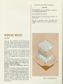
made with shielded audio cables. Figure 2 shows
the location of the input and output jacks on the
rear panel. These are for "permanent" connections.
Use of the front panel controls and jacks will be
discussed later. A letter "L" corresponds to the left
audio channel; a letter "R" to right audio channel.
To avoid confusion, it is suggested that you
connect one cable at a time between the Model
1060 and the other components of your system.
This way, mixing up the channels or mixing up
signal sources and destinations will be avoided.
D
u
The SPEAKER SYSTEM (MAIN, REMOTE) jacks
on the left side of the rear panel will accomodate
two loudspeaker systems; each speaker having a
rated impedance between 4 and 16 ohms. When
using only one pair of speakers, connect them to
the terminals marked MAIN. The terminals marked
REMOTE are used for connection a second pair of
speakers in a location remote to the Model 1060.
Use care when connecting the Model 1060 to a
loudspeaker which contains a built-in power
supply-such as an electrostatic loudspeaker. The
"common" speaker-connection terminal of these
devices may be capacitively coupled through the
power supply. Ensure that the (-) terminals of the
model 1060 are connected to the "common"
terminals of the loudspeaker system as shown in
Figure 1. Ordinary #18 gauge two-conductor lamp
cord may be used for distances of up to 30 feet
between amplifier and loudspeakers. For longer
distances, use #16 gauge wire or heavier, depending
on length.
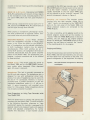
In connecting two loudspeakers for stereo operation, it is important to insure correct relative
phasing (polarity). This is best acheived, when
using identical loudspeakers, by simply coding each
wire for identification,
one wire in each pair
should be coded at both ends with a knot, tape,
etc. The coded wires can then be used for identical
connections in each channel. For example, the
coded wire in each pair can be connected to the
"common" terminal of each loudspeaker and the
(-) terminal of each amplifier channel. The uncoded wire of each pair is then connected to the
remaining loudspeaker terminal and the remaining
terminal on each amplifier channel (R and L). This
procedure insures correct polarity or phasing of
identical loudspeakers.
Note: Close inspection of standard zipcord will
reveal some form of coding on the insulation (ridge
or groove on one edge); or one of the wires may be
tinned and the other wire not tinned.
CAUTION: Never directly connect the loudspeaker
terminals of one channel in parallel with those of
any other. Any resulting damage is not covered
under warranty.
2