1
CMA Series
Commercial Mixer/Amplifiers
Operation Manual
®
6/14/99
Biamp Systems, 10074 S.W. Arctic Drive, Beaverton, Oregon 97005 U.S.A. (503) 641-7287
an affiliate of Rauland Borg Corp.
CMA Series
TABLE OF CONTENTS
INTRODUCTION
Front Panel Features
pg. 2
Rear Panel Features
pg. 4
Modifications
pg. 6
Applications
pg. 8
Specifications
pg. 12
Block Diagram
pg. 13
Warranty
The CMA Series of commercial mixer/amplifiers combines a versatile 6-input
mic/line mixer with either 30, 60, 120, or 350 Watt amplification. Mixing
functions include mic/line/telephone inputs, selectable automatic & manual
channel muting, channel priority assignment, remote level control, tone control,
a built-in compressor, an internal chime, phantom power, and extensive output
patching. The amplifier includes an output transformer, and provides rated
power into direct or distributed speaker systems. The CMA Series carries a
five-year warranty.
CMA Series features include:
♦ integrated mixer, power amplifier, and output transformer
♦ five electronically balanced microphone/line input channels
♦ one transformer balanced microphone/line/tel input channel
♦ rear panel trim control & pad switch on each input channel
♦ +24 Volt phantom power selectable on each input channel
♦ input isolation transformer option on mic/line input channels
♦ automatic muting of selected channels (-10, -20, or -40dB)
♦ automatic muting triggered by selected "priority" channels
♦ manual muting of selected channels (-10, -20, or -40dB)
♦ manual muting triggered from remote contact closures
♦ remote control of master level via rear panel terminals
♦ integral output compressor with rear panel threshold control
♦ recessed treble & bass controls plus "loudness" & "low-cut"
♦ two insert points for signal processing and remote control
♦ two line-outs and one stack-in for system interconnections
♦ 30, 60, 120, or 350 Watts into direct or distributed systems
♦ front panel indicators for power, fault, signal, and peak
♦ internal 'pre-announcement' chime tone with level control
♦ input/output connections provided on barrier strip terminals
♦ integral security cover and removable rack-wing/handles
♦ covered by Five-Year "Gold Seal" Warranty
♦
marked, UL and C-UL (UL Canada) listed
1
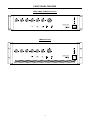
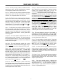
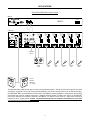
FRONT PANEL FEATURES
CMA30, CMA60, & CMA120 Front Panels
peak
signal
fault
1
2
3
4
6
5
master
on
0
off
on
on
off
PRECEDENCE CMA120
Commercial Mixer Amplifier
on
off
loudness
contour
low cut
0
+
bass
tone
control
+
treble
power
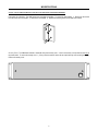
CMA350 Front Panel
peak
signal
fault
1
2
3
4
6
5
master
power
0
off
on
low cut
off
on
loudness
contour
0
PRECEDENCE CMA350
Commercial Mixer Amplifier
on
off
+
bass
tone
control
2
+
treble
I
O
FRONT PANEL FEATURES
Peak Indicator: This red LED flashes when signal levels at the
amplifier output have reached maximum. Occasional flashes of
the Peak Indicator are acceptable, however, a continuously lit LED
may indicate an excessive level setting.
Level (Channels 1~6): These controls adjust the amount of
signal sent from the individual input channels to the mixer output.
Optimum Level setting is near the 12 o'clock position (unity gain).
Level (Master): This control adjusts the amount of signal sent
from the mixer output to the amplifier input. The Master Level
control is used to adjust the overall volume of the system.
Signal Indicator: This yellow LED remains lit when signal is
present at the amplifier output.
Fault Indicator: This red LED lights to indicate fault conditions
due to overheating, DC offset voltage, or failure of low-voltage
power. The Fault Indicator will light for 3-5 seconds at turn-on, and
then go off if no fault is detected. Some faults (such as
overheating) will correct themselves when the unit has been turned
off awhile. If the Fault Indicator remains lit when the unit is turned
back on, contact your local Biamp Systems dealer.
Low Cut: This switch inserts a low cut filter at the amplifier input.
Loudness Contour: This switch inserts a loudness filter at the
mixer output (+6dB @ 100Hz & +4dB @ 10kHz). The Loudness
filter provides tonal compensation when operating with low-level
music signals.
Tone Control: This switch enables the Bass & Treble controls.
On Indicator: This green LED remains lit when AC power is
applied to the unit.
Bass: This screwdriver control adjusts the low-frequencies
("Bass") at the mixer output (±10dB @ 100Hz).
Power Switch: This switch applies AC power to the unit.
Treble: This screwdriver control adjusts the high-frequencies
("Treble") at the mixer output (±10dB @ 10kHz).
3
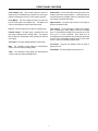
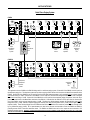
REAR PANEL FEATURES
CMA30, CMA60, & CMA120 Rear Panels
pre
out
channel 2
channel 1
phantom pwr
auto mute
manual mute
mute -40
level -20
phantom pwr
auto mute
manual mute
mute -40
level -20
trim
ina
priority
25V
compressor
6.3A - 115V
out
50V
min
70V
3.15A -230V
remote
level
+10V c
auto mute
on
off
priority
ina
max
trim
min
on
off
priority
line
mic
ina
max
trim
min
on
off
max
trim
min
on
off
priority
line
mic
ina
priority
line
mic
ina
max
trim
min
on
off
ina
max
min
on
off
priority
line
mic
line
mic
min
mute/
chime stacking in
tel
+
USE ONLY WITH
250V FUSE
trim
line
mic
max
threshold adjust
max
min
8
R
C
~ 115/230V
channel 3
phantom pwr
auto mute
manual mute
mute -40
level -20
nom
amp
in
channel 4
phantom pwr
auto mute
manual mute
mute -40
level -20
nom
min
rec
out
channel 5
phantom pwr
auto mute
manual mute
mute -40
level -20
nom
line
out
channel 6
phantom pwr
auto mute
manual mute
mute -40
level -20
nom
com
max
nom
chime
level
4
E158021
LISTED 2 Z 91
COMMERCIAL
AUDIO EQUIP
R
send/return
an affiliate of
Rauland-Borg Corp
direct
nom
BIAMP SYSTEMS
120watt
output
xfmr
+
+
+
+
+
+
AC 50/60 Hz 375 VA
CMA350 Rear Panel
send/return
115
R
pre
out
amp
in
inal
max
min
priority
R
WARNING:
compressor
do not change
AC voltage switch
when power is on.
out
350 watt
output
min
inal
max
min
trim
inal
on
off
on
off
line
mic
line
mic
channel 3
phantom pwr
auto mute
manual mute
mute -40
level -20
max
min
priority
priority
on
off
C
trim
channel 4
phantom pwr
auto mute
manual mute
mute -40
level -20
trim
inal
channel 2
max
min
priority
trim
inal
max
min
trim
inal
max
min
priority
priority
on
off
channel 1
phantom pwr
auto mute
manual mute
mute -40
level -20
phantom pwr
auto mute
manual mute
mute -40
level -20
nom
rec
out
trim
LISTED 2 Z 91
COMMERCIAL
AUDIO EQUIP
channel 5
phantom pwr
auto mute
manual mute
mute -40
level -20
nom
line
out
E158021
phantom pwr
auto mute
manual mute
mute -40
level -20
nom
an affiliate of Rauland-Borg Corp.
min
nom
Portland, Oregon
max
nom
channel 6
chime
level
nom
CMA350
BIAMP SYSTEMS
on
off
on
off
auto mute
threshold adjust
max
min
line
mic
line
mic
line
mic
line
mic
tel
xfmr
direct
stacking in
70V 50V 25V 8
~ 115/230V
channel 5
channel 4
channel 3
channel 2
channel 1
mute/
chime
6.3A - 115V
com 4
remote
level c
+
+
+
+
+
+10V
+
3.15A -230V
+
USE ONLY WITH
250V FUSE
channel 6
AC 50/60 Hz 700 VA
Power Entrance: This receptacle accepts a 3-prong AC power
cord. WARNING: DO NOT REMOVE OR DEFEAT THE GROUND PRONG, AS
THIS CONSTITUTES A SHOCK HAZARD. The removable lower portion
of the receptacle holds the AC fuse. NOTE: See AC Fuse on
page 7 for replacement by qualified personnel. A chassis ground
post is provided (next to the receptacle) for system grounding.
Output Terminals: These screw terminals provide connection for
speaker loads (4Ω, 8Ω, 25V, 50V, 70V, or 100V) at the amplifier
output. NOTE: 100V output is an export model option only.
Power Selector Switch (model CMA350 only): This switch
selects either 115 Volt or 230 Volt AC operation for model CMA350
(see Modifications on pg. 7). Power Selector Switches for other
models are on the underside of the chassis.
Chime Level: This control adjusts the volume level of the chime
tone (see Mute/Chime on next page). To turn the chime tone off
completely, set this control to the fully counter-clockwise position.
Output Selector: This switch selects either direct output or
transformer coupled output from the amplifier. On models CMA60,
CMA120, & CMA350 direct output is from the 4Ω terminal. On
model CMA30, direct output is from the 8Ω terminal.
Send/Return: This 3-conductor TRS 1/4" Phone jack provides an
insert point for signal processing or remote control devices. It is
wired with Tip as send, Ring as return, and Sleeve as ground.
Send/Return is after Stacking In, Loudness, & Tone, but before
Compressor, Master Level, & Low Cut. Send/Return is a switching
jack, which interrupts the signal flow only when a plug is inserted.
WARNING: THE LOUDSPEAKER OUTPUTS POSE A RISK OF HAZARDOUS
ENERGY. LOUDSPEAKER CONNECTIONS MUST BE MADE PROPERLY.
THE OUTPUT TERMINAL COVER MUST BE INSTALLED WHEN THE DEVICE
IS ENERGIZED.
4
REAR PANEL FEATURES
Stacking In: These screw terminals provide a balanced line-level
input to the mix bus, for input expansion. Stacking In is before
Loudness, Tone, Compressor, Master Level, & Low Cut. For
unbalanced input, wire high to (+) and ground to both (-) & ( ).
Assignment: These five DIP switches are used to assign specific
functions to the individual channels. To assign a function, move
the respective switch to the left. Phantom Pwr assigns +24 Volts
DC phantom power to the channel input, for powering condenser
microphones. CAUTION: TO AVOID DAMAGE TO EQUIPMENT, ASSIGN
Line Out: This RCA phono jack provides an unbalanced line-level
output from the mixer. Line Out is after Stacking In, Loudness,
Tone, Compressor, & Master Level, but before Low Cut.
➽
Rec Out: This RCA phono jack provides an unbalanced line-level
output from the mixer. Rec Out is after Stacking In, but before
Loudness, Tone, Compressor, Master Level, & Low Cut.
Pre Out: This RCA phono jack provides an unbalanced line-level
output from the mixer. Pre Out is after Stacking In, Loudness, &
Tone, but before Compressor, Master Level, & Low Cut. Pre Out
and Amp In may be used together as an insert point for signal
processing or remote control devices. Remove jumper before
connecting devices. To connect Pre Out to both Amp In and an
external device, a parallel (‘Y’) cable must be used.
PHANTOM POWER ONLY ON CHANNELS WHICH ARE SELECTED FOR 'MIC'
INPUT AND WHICH REQUIRE PHANTOM POWER. Auto Mute assigns a
(non-priority) channel to be muted whenever signal is present in
any "priority" channel. Manual Mute assigns a channel to be
muted whenever the Mute/Chime terminals are shorted together
via a switch or contact closure. Mute Level assigns the amount of
muting (-10dB, -20dB, or -40dB) which is applied to a channel,
when triggered by either Auto Mute or Manual Mute. NOTE:
-10dB muting will occur when both switches are to the right.
-40dB muting will occur when both switches are to the left.
Amp In: This RCA phono jack provides an unbalanced line-level
input to the amplifier. Amp In is after Stacking In, Loudness, &
Tone, but before Compressor, Master Level, & Low Cut. Pre Out
and Amp In may be used together as an insert point for signal
processing or remote control devices. Remove jumper before
connecting devices.
Trim: This control adjusts the input gain of the channel, to
compensate for various input signal levels. Once the Line/Mic
switch has been set to the proper position (see Line/Mic below),
the Trim control should be adjusted so that peaks in signal level do
not cause distortion at the channel input.
Compressor: This control adjusts the threshold level at which the
internal compressor circuit is activated. The internal compressor
has a fixed compression ratio of 4:1, and is used to reduce peaks
in output signal level, as well as to moderate volume differences
between loud and soft signals.
Priority: This switch assigns a channel to "priority". When signal
is present in a "priority" channel, any (non-priority) channels which
are assigned to Auto Mute will be muted by their selected amount.
NOTE: A "priority" channel cannot be auto muted by another
"priority" channel, but a "priority" channel can be manual muted.
Auto Mute: This control adjusts the threshold level at which
signals from "priority" channels will automatically trigger muting of
selected non-priority channels (see Assignment & Priority below).
Line/Mic: This switch selects the proper impedance and gain for
either microphone or line-level input signals. Depress the switch
for line-level input. Release the switch for microphone input. On
Channel 1, the Tel switch (see Tel below) must be released for the
Line/Mic switch to operate.
Remote Level: These two screw terminals (plus " ") provide
remote volume control of the master level. An internal voltage
controlled amplifier (VCA) allows remote control from up to 2000
feet away, using any 5k~50kΩ linear taper potentiometer and/or
switch to provide adjustment and/or muting of the master level.
Potentiometers are wired with high-side to "+10V", low-side to " ",
and wiper to "C". Switches simply connect (or disconnect) "+10V"
to "C", and do not require a ground (‘ ’) connection. NOTE: The
factory installed jumper (between "+10V" & "C") must be in place
when a remote control is not being used.
➽
Tel (Channel 1 only): This switch selects the proper impedance
and gain for input from 600 ohm sources. The input for Channel 1
includes an isolation transformer, which allows connection to most
telephone system audio ports.
➽
➽
Inputs: These screw terminals provide a balanced input
connection for the channel. For unbalanced input, wire high to (+)
and ground to both (-) & ( ). The input for Channel 1 includes an
isolation transformer. Input isolation transformers are optional on
Channels 2~6 (Biamp #908-0040-00).
Mute/Chime: This screw terminal (plus " ") allows manual muting
of any selected channels, via an external switch or contact closure
(see Assignment & Priority below). When the Chime Level control
is turned up (on), a pre-announcement chime tone will also be
activated by the switch or contact closure.
➽
➽
5
MODIFICATIONS
CAUTION: THE FOLLOWING INFORMATION IS FOR USE BY QUALIFIED INSTALLATION/SERVICE PERSONNEL.
Removable Rack-Handles: The CMA Series have removable rack-handles. To remove the rack-handles: 1) Remove the two screws
from the side of each rack-handle. 2) Remove the rack-handles. 3) Replace the mounting screws in the sides of the chassis.
Security Cover: The CMA Series includes a removable front panel security cover. A hole in the security cover provides access only to
the power switch. To remove the security cover: 1) Using a 3mm hex wrench, loosen the two captive security cover mounting screws. 2)
Remove the security cover.
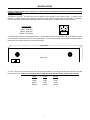
6
MODIFICATIONS
WARNING: TO REDUCE THE RISK OF SHOCK, DISCONNECT ALL POWER FROM THE UNIT BEFORE MAKING ANY INTERNAL MODIFICATIONS OR EXTERNAL
FIELD WIRING CONNECTIONS.
115V/230V AC Operation: The CMA Series may be converted to 230V operation for use in other countries. To convert to 230V
operation: 1) Remove the fuse holder compartment from the lower portion of the rear panel AC Power Cord receptacle. 2) Replace the
fuse in the fuse clip with the same type and appropriate value fuse (see table below). 3) Replace the fuse holder compartment.
230V fuse values
CMA30 - 1A NB 250V
CMA60 - 2A NB 250V
CMA120 - 3A NB 250V
CMA350 - 3.15A SB 250V
USE ONLY WITH
250V FUSE
4) Select the 230V position on the Power Selector Switch. The Power Selector Switch for models CMA30, CMA60, & CMA120 is recessed
into the underside of the chassis, near the AC Power Cord receptacle. The Power Selector Switch for model CMA350 is instead located on
the left side of the rear panel, above the AC Power Cord receptacle.
rear panel
bottom panel
115V
230V
AC Fuse: The AC Fuse is in the lower portion of the AC Power Cord receptacle. If the AC fuse should require replacement, see table
below for proper value. WARNING: FOR CONTINUED PROTECTION AGAINST RISK OF FIRE, REPLACE ONLY WITH SAME VALUE AND TYPE FUSE.
MODEL
CMA30
CMA60
CMA120
CMA350
115 VAC
2A NB
4A NB
6A NB
6.3A SB
7
230 VAC
1A NB
2A NB
3A NB
3.15A SB
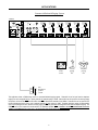
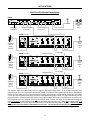
APPLICATIONS
Commercial/Industrial Paging System
CMA60
R
amp
in
pre
out
channel 2
channel 1
phantom pwr
auto mute
manual mute
mute -40
level -20
phantom pwr
auto mute
manual mute
mute -40
level -20
priority
compressor
out
50V
min
~ 115/230V
channel 3
phantom pwr
auto mute
manual mute
mute -40
level -20
trim
25V
6.3A - 115V
3.15A -230V
channel 4
phantom pwr
auto mute
manual mute
mute -40
level -20
8
C
USE ONLY WITH
250V FUSE
channel 5
phantom pwr
auto mute
manual mute
mute -40
level -20
70V
remote
level
+10V c
auto mute
threshold adjust
mute/
chime stacking in
+
ina
max
trim
min
on
off
priority
line
mic
max
on
off
ina
max
trim
min
priority
line
mic
on
off
ina
max
trim
min
priority
line
mic
ina
max
trim
min
on
off
priority
line
mic
on
off
ina
max
trim
min
priority
line
mic
nom
rec
out
channel 6
phantom pwr
auto mute
manual mute
mute -40
level -20
nom
line
out
min
nom
com
max
nom
E158021
LISTED 2 Z 91
COMMERCIAL
AUDIO EQUIP
chime
level
nom
4
R
send/return
an affiliate of
Rauland-Borg Corp
direct
nom
BIAMP SYSTEMS
60 watt
output
xfmr
ina
max
min
on
off
line
mic
min
tel
+
+
+
+
+
+
AC 50/60 Hz 375 VA
background
music
source
security
paging
mic
telephone
paging
line
70V
distributed
speaker
system
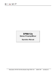
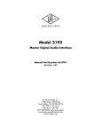
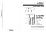
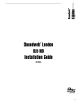
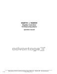
This application shows a CMA60 being used in a commercial/industrial paging system. Channel #1 is set for input from the telephone
paging line, and is assigned both as a priority channel and manual muting of -20dB. Channel #2 is set for input from the security paging
microphone, which also has a push-to-talk switch wired to the Mute/Chime terminals of the CMA60. Channel #3 is set for input from the
line-level background music source, and is assigned manual and auto muting of -20dB. Therefore, telephone paging will automatically
mute only the background music, whereas, security paging will manually mute both the background music and the telephone paging. The
CMA60 is set for 'xfmr' output and is connected to a 70V distributed speaker system. WARNING: THE ABOVE DIAGRAM SHOWS THE OUTPUT
TERMINAL COVER REMOVED FOR CLARITY ONLY. THE COVER MUST BE INSTALLED WHEN THE UNIT IS ENERGIZED.
8
APPLICATIONS
Church Sound Reinforcement System
MSP11
~
27V
50/60 Hz
output
BIAMP SYSTEMS
Portland, Oregon
input
serial port
output
12 watts
class 2 wiring
link port
link
an affiliate of
Rauland-Borg Corp.
MSP11
input
MADE IN U.S.A.
logic inputs
CMA120
R
pre
out
compressor
6.3A - 115V
out
50V
min
~ 115/230V
channel 2
channel 1
phantom pwr
auto mute
manual mute
mute -40
level -20
phantom pwr
auto mute
manual mute
mute -40
level -20
trim
25V
USE ONLY WITH
250V FUSE
channel 3
phantom pwr
auto mute
manual mute
mute -40
level -20
ina
8
C
3.15A -230V
channel 4
phantom pwr
auto mute
manual mute
mute -40
level -20
70V
remote
level
+10V c
trim
min
ina
max
trim
min
ina
max
trim
min
ina
max
trim
min
ina
max
trim
min
on
priority off
on
priority off
on
priority off
on
priority off
on
priority off
line
mic
line
mic
line
mic
line
mic
line
mic
line
mic
max
ina
max
min
on
priority off
auto mute
threshold adjust
max
nom
amp
in
channel 5
phantom pwr
auto mute
manual mute
mute -40
level -20
nom
min
rec
out
channel 6
phantom pwr
auto mute
manual mute
mute -40
level -20
nom
line
out
max
nom
com
chime
level
nom
4
E158021
LISTED 2 Z 91
COMMERCIAL
AUDIO EQUIP
R
send/return
an affiliate of
Rauland-Borg Corp
direct
nom
BIAMP SYSTEMS
120 watt
output
xfmr
min
mute/
chime stacking in
+
tel
+
+
+
+
+
+
AC 50/60 Hz 375 VA
auxiliary
mixer
tape
deck
choir
mic
choir
mic
wireless
mic
lectern
mic
pulpit
mic
two 8Ω
speaker
cabinets
(4Ω load)
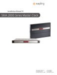
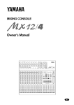
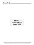
This application shows a CMA120 being used in a church sound reinforcement system. Channels #1~5 are set for input from the various
microphones. Channel #6 is set for input from the tape deck (playback), which is also connected to Rec Out of the CMA120 (recording).
An ADVANTAGE® MSP11 is inserted between Pre Out & Amp In of the CMA120, providing equalization to compensate for room acoustics,
and automatic gain control for consistent output levels. If additional inputs are required, an auxiliary mixer (such as an ADVANTAGE®
601e) may be connected to the Stacking In terminals of the CMA120. The CMA120 is set for 'direct' (4Ω) output and is connected (in
parallel) to the two 8Ω speaker cabinets. WARNING: THE ABOVE DIAGRAM SHOWS THE OUTPUT TERMINAL COVER REMOVED FOR CLARITY ONLY.
THE COVER MUST BE INSTALLED WHEN THE UNIT IS ENERGIZED.
9
APPLICATIONS
Retail Store Paging System
CMA30
R
channel 1
phantom pwr
auto mute
manual mute
mute -40
level -20
trim
priority
25V
compressor
6.3A - 115V
out
50V
min
remote
level
+10V c
70V
auto mute
inal
max
trim
min
on
off
priority
line
mic
max
threshold adjust
inal
max
trim
min
on
off
priority
line
mic
inal
max
trim
min
on
off
priority
line
mic
inal
max
trim
min
on
off
priority
line
mic
inal
max
trim
min
on
off
priority
line
mic
inal
max
min
on
off
line
mic
min
mute/
chime stacking in
tel
+
USE ONLY WITH
250V FUSE
~ 115/230V
channel 2
phantom pwr
auto mute
manual mute
mute -40
level -20
4
C
3.15A -230V
channel 3
phantom pwr
auto mute
manual mute
mute -40
level -20
nom
pre
out
amp
in
channel 4
phantom pwr
auto mute
manual mute
mute -40
level -20
nom
min
rec
out
channel 5
phantom pwr
auto mute
manual mute
mute -40
level -20
nom
line
out
channel 6
phantom pwr
auto mute
manual mute
mute -40
level -20
nom
com
max
nom
chime
level
8
E158021
LISTED 2 Z 91
COMMERCIAL
AUDIO EQUIP
R
send/return
an affiliate of
Rauland-Borg Corp
direct
nom
BIAMP SYSTEMS
30 watt
output
xfmr
+
+
+
+
+
+
AC 50/60 Hz 375 VA
RP-L2
store
level
store
distributed
speaker
system
background
music
source
warehouse
level
RP-L2
digital
message
repeater
telephone
paging
line
CMA120
R
pre
out
channel 1
phantom pwr
auto mute
manual mute
mute -40
level -20
trim
priority
25V
compressor
6.3A - 115V
out
50V
min
70V
USE ONLY WITH
250V FUSE
~ 115/230V
channel 2
phantom pwr
auto mute
manual mute
mute -40
level -20
8
C
3.15A -230V
channel 3
phantom pwr
auto mute
manual mute
mute -40
level -20
remote
level
+10V c
auto mute
threshold adjust
mute/
chime stacking in
+
on
off
inal
max
trim
min
priority
line
mic
max
on
off
inal
max
trim
min
priority
line
mic
on
off
inal
max
trim
min
priority
line
mic
on
off
inal
max
trim
min
priority
line
mic
inal
max
trim
min
on
off
priority
line
mic
nom
amp
in
channel 4
phantom pwr
auto mute
manual mute
mute -40
level -20
nom
min
rec
out
channel 5
phantom pwr
auto mute
manual mute
mute -40
level -20
nom
line
out
channel 6
phantom pwr
auto mute
manual mute
mute -40
level -20
nom
com
max
nom
chime
level
4
E158021
LISTED 2 Z 91
COMMERCIAL
AUDIO EQUIP
R
send/return
an affiliate of
Rauland-Borg Corp
direct
nom
BIAMP SYSTEMS
120 watt
output
xfmr
inal
max
min
on
off
line
mic
min
tel
+
+
+
+
+
+
AC 50/60 Hz 375 VA
warehouse
distributed
speaker
system
warehouse
paging
mic
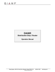
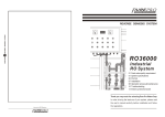
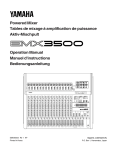
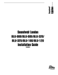
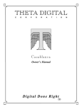
This application shows a CMA30 and a CMA120 being used in a retail store paging system. Channel #1 of the CMA30 is set for input from
the telephone paging line. The telephone system also provides a paging contact closure which is wired to the Mute/Chime terminals of the
CMA30. Channel #2 of the CMA30 is set for input from the line-level digital message repeater, and is assigned both as a priority channel
and manual muting of -20dB. Channel #3 of the CMA30 is set for input from the line-level background music source, and is assigned
manual and auto muting of -10dB. Channel #1 of the CMA120 is set for input from the warehouse paging microphone, which also has a
push-to-talk switch wired to the Mute/Chime terminals of the CMA120. Channel #6 of the CMA120 is set for input from the line-level Pre
Out of the CMA30, and is assigned manual muting of -40dB. Therefore, the digital message repeater will automatically mute only the
background music (-10dB), whereas, telephone paging will manually mute both the background music (-10dB) and the digital message
repeater (-20dB). These combined signals from the CMA30 are then fed to the CMA120 in the warehouse, where they are manually muted
by any warehouse paging (-40dB). RP-L2 potentiometers are wired to the Remote Level terminals of both the CMA30 and CMA120,
providing remote control of store and warehouse levels. The CMA30 and CMA120 are set for 'xfmr' output and are connected to 70V
distributed speaker systems. WARNING: THE ABOVE DIAGRAM SHOWS THE OUTPUT TERMINAL COVER REMOVED FOR CLARITY ONLY. THE COVER
MUST BE INSTALLED WHEN THE UNIT IS ENERGIZED.
10
APPLICATIONS
Multi-Floor Office/Hospital Paging System
DA28R
OUTPUTS
DA28R
INPUTS
BIAMP SYSTEMS
invert logic
phantom
invert logic
phantom
~
27V
50/60 Hz
Portland, Oregon
an affiliate of Rauland-Borg Corp.
level
level
level
level
level
level
level
level
trim
trim
pad
output 8
output 7
output 6
output 4
output 5
output 3
background music
to Floors #1~3
input/output
assignment
output 2
output 1
pad
+10
CH 1
logic inputs
CH 2
+10
12 watts
class 2 wiring
CH 2
CH 1
background
music
source
all-call paging
to Floors #1~3
CMA60 (Floor #1)
pre
out
amp
in
channel 2
channel 1
phantom pwr
auto mute
manual mute
mute -40
level -20
phantom pwr
auto mute
manual mute
mute -40
level -20
trim
priority
25V
compressor
6.3A - 115V
out
50V
min
70V
remote
level
+10V c
auto mute
inal
max
priority
trim
min
priority
line
mic
+
R
inal
max
trim
min
on
off
priority
line
mic
+
inal
max
trim
min
on
off
priority
line
mic
+
inal
max
min
on
off
Floor #1
local
paging
mic
line
mic
+
+
channel 4
channel 3
channel 2
channel 1
phantom pwr
auto mute
manual mute
mute -40
level -20
phantom pwr
auto mute
manual mute
mute -40
level -20
phantom pwr
auto mute
manual mute
mute -40
level -20
phantom pwr
auto mute
manual mute
mute -40
level -20
trim
priority
inal
25V
compressor
6.3A - 115V
out
50V
min
70V
remote
level
+10V c
auto mute
priority
inal
max
trim
min
on
off
priority
line
mic
inal
max
trim
min
on
off
priority
line
mic
inal
max
trim
min
on
off
priority
line
mic
inal
max
trim
min
on
off
priority
line
mic
inal
max
min
on
off
Floor #2
local
paging
mic
line
mic
min
mute/
chime stacking in
tel
+
USE ONLY WITH
250V FUSE
trim
min
line
mic
max
threshold adjust
max
on
off
nom
pre
out
amp
in
channel 5
phantom pwr
auto mute
manual mute
mute -40
level -20
nom
rec
out
channel 6
phantom pwr
auto mute
manual mute
mute -40
level -20
8
C
3.15A -230V
all-call paging
nom
min
nom
line
out
max
nom
com
chime
level
nom
LISTED 2 Z 91
COMMERCIAL
AUDIO EQUIP
+
+
+
+
+
+
AC 50/60 Hz 375 VA
R
line
out
min
rec
out
amp
in
pre
out
channel 4
channel 3
channel 2
channel 1
phantom pwr
auto mute
manual mute
mute -40
level -20
phantom pwr
auto mute
manual mute
mute -40
level -20
phantom pwr
auto mute
manual mute
mute -40
level -20
phantom pwr
auto mute
manual mute
mute -40
level -20
trim
priority
25V
compressor
6.3A - 115V
out
50V
min
3.15A -230V
channel 5
phantom pwr
auto mute
manual mute
mute -40
level -20
8
C
USE ONLY WITH
250V FUSE
channel 6
phantom pwr
auto mute
manual mute
mute -40
level -20
70V
remote
level
+10V c
auto mute
threshold adjust
mute/
chime stacking in
+
on
off
inal
max
trim
min
priority
line
mic
max
on
off
inal
max
trim
min
priority
line
mic
on
off
inal
max
trim
min
priority
line
mic
on
off
inal
max
trim
min
priority
line
mic
on
off
inal
max
trim
min
priority
line
mic
nom
com
max
nom
E158021
LISTED 2 Z 91
COMMERCIAL
AUDIO EQUIP
chime
level
nom
4
nom
send/return
an affiliate of
Rauland-Borg Corp
direct
nom
BIAMP SYSTEMS
60 watt
output
xfmr
all-call paging
background music
CMA60 (Floor #3)
~ 115/230V
max
tel
+
send/return
an affiliate of
Rauland-Borg Corp
direct
E158021
70V
distributed
speaker
system
(Floor #3)
priority
inal
on
off
background music
4
R
trim
min
min
+
BIAMP SYSTEMS
60 watt
output
~ 115/230V
max
AC 50/60 Hz 375 VA
xfmr
70V
distributed
speaker
system
(Floor #2)
inal
on
off
line
mic
CMA60 (Floor #2)
R
trim
min
on
off
line
mic
max
threshold adjust
mute/
chime stacking in
USE ONLY WITH
250V FUSE
~ 115/230V
channel 3
phantom pwr
auto mute
manual mute
mute -40
level -20
8
C
3.15A -230V
channel 4
phantom pwr
auto mute
manual mute
mute -40
level -20
nom
rec
out
channel 5
phantom pwr
auto mute
manual mute
mute -40
level -20
nom
line
out
channel 6
phantom pwr
auto mute
manual mute
mute -40
level -20
nom
com
min
nom
70V
distributed
speaker
system
(Floor #1)
R
max
nom
E158021
LISTED 2 Z 91
COMMERCIAL
AUDIO EQUIP
chime
level
nom
4
R
send/return
an affiliate of
Rauland-Borg Corp
direct
nom
BIAMP SYSTEMS
60 watt
output
xfmr
on
off
line
mic
min
tel
+
+
AC 50/60 Hz 375 VA
+
+
+
+
inal
max
min
Floor #3
local
paging
mic
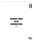
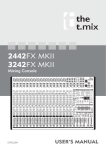
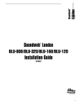
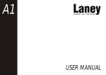
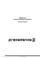
This application shows three CMA60s being used in a multi-floor office/hospital paging system. An all-call paging microphone and a
background music source are connected to an ADVANTAGE® DA28R, which distributes those signals independently to the three CMA60s.
Channel #1 of each CMA60 is set for input from line-level all-call paging, and is assigned as a priority channel. Channel #2 of each CMA60
is set for input from the respective floor paging microphone, and is assigned auto muting of -40dB. The push-to-talk switch of each floor
paging microphone is wired to the Mute/Chime terminals of the respective CMA60. Channel #3 of each CMA60 is set for input from linelevel background music, and is assigned manual and auto muting of -20dB. Therefore, local paging will manually mute the background
music only on that floor (-20dB), whereas, all-call paging will automatically mute background music (-20dB) and local paging (-40dB) on all
floors. The CMA60s are set for 'xfmr' output and are connected to 70V distributed speaker systems for each floor. WARNING: THE ABOVE
DIAGRAM SHOWS THE OUTPUT TERMINAL COVER REMOVED FOR CLARITY ONLY. THE COVER MUST BE INSTALLED WHEN THE UNIT IS ENERGIZED.
11
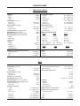
SPECIFICATIONS
CMA30, CMA60, & CMA120
Output Power:
CMA 30
CMA 60
CMA 120
Power Bandwidth (THD < 0.4%):
direct output
transformer output
Frequency Response (+0/-1.5dB):
direct output
transformer output
Total Harmonic Distortion (1kHz @ rated power):
Output Regulation (no load to full load)
Equivalent Input Noise (mic in, 150Ω termination):
Signal-to-Noise Ratio (20Hz-20kHz @ rated power):
line inputs
telephone inputs
master level off
Compressor:
attack time
release time
compression ratio
threshold adjust range
Dimensions (all models; includes rack/handles & feet):
height (two rack spaces)
width
depth
30 Watts
60 Watts
120 Watts
20Hz~20kHz
50Hz~20kHz
20Hz~20kHz
50Hz~20kHz
< 0.2%
< 0.5dB
-123dBu
Input Impedance / Sensitivity
mic inputs
line inputs
telephone inputs
amplifier input
stacking input
patch/return input
6kΩ / -77dBu (110µV)
15kΩ / -37dBu (14mV)
600Ω / -60dBu (775µV)
10kΩ / +4dBu (1.2V)
20kΩ / -8dBu (300mV)
10kΩ / -8dBu (300mV)
Output Impedance / Level:
preamp output & line output
record output
patch/send output
200Ω / +4dBu (1.2V)
200Ω / +4dBu (1.2V)
50Ω / -8dBu (300mV)
Amplifier Output Impedance / Level:
CMA 30
CMA 60
4Ω / 11V
4Ω / 16V
8Ω / 16V
8Ω / 22V
20.8Ω / 25V
10.4Ω / 25V
83.3Ω / 50V
41.7Ω / 50V
163.3Ω / 70V
81.7Ω / 70V
333.3Ω / 100V (export)
166.7Ω / 100V (export)
Power Consumption (120VAC 60Hz / 240VAC 50Hz):
CMA 30
CMA 60
< 90W
< 220W
78dB
78dB
98dB
< 1mSecond
> 1 Second
4:1
15dB
Weight:
CMA 30
CMA 60
CMA 120
3.68" (93.5mm)
19" (482mm)
14.33" (364mm)
CMA 120
4Ω / 22V
8Ω / 31V
5.2Ω / 25V
20.8Ω / 50V
40.8Ω / 70V
83.3Ω / 100V (export)
CMA 120
< 375W
17.64 lbs. (8kg)
22 lbs. (10kg)
26.45 lbs. (12kg)
CMA350
Output Power:
Power Bandwidth (THD < 0.5%):
direct output
transformer output
Frequency Response (+0/-1.5dB):
direct output
transformer output
THD + Noise (1kHz @ rated power):
Output Regulation (no load to full load)
Equivalent Input Noise (mic in, 150Ω termination):
Signal-to-Noise Ratio (20Hz-20kHz @ rated power):
line inputs & telephone input
master level off
Input Impedance / Sensitivity
mic inputs
line inputs
telephone inputs
amplifier input
stacking input
patch/return input
350 Watts
Output Impedance / Level:
record output, preamp output, & line output
patch/send output
20Hz~20kHz
50Hz~20kHz
200Ω / +4dBu (1.2V)
50Ω / -8dBu (300mV)
Amplifier Output Impedance / Level:
4Ω / 37.4V
8Ω / 53V
1.8Ω / 25V
7.1Ω / 50V
14Ω / 70V (28.6Ω / 100V export)
20Hz~20kHz
50Hz~20kHz
< 0.25%
< 0.5dB
-123dBu
Compressor:
attack time
release time
compression ratio
threshold adjust range
Power Consumption (120/240VAC 60/50Hz):
Dimensions (includes rack/handles & feet):
height (three rack spaces)
78dB
98dB
6kΩ / -77dBu (110µV)
15kΩ / -37dBu (14mV)
600Ω / -60dBu
(775µV)
10kΩ / +4dBu (1.2V)
20kΩ / -8dBu (300mV)
10kΩ / -8dBu (300mV)
width
depth
Weight:
12
< 1mSecond
> 1 Second
4:1
15dB
< 760 Watts
5.24" (133mm)
19" (483mm)
14" (356mm)
51 lbs. (23.13kg)
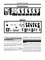
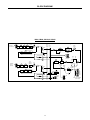
BLOCK DIAGRAM
Channel 1
(mic/line/tel)
+
-
telephone
mic/
line
trim
priority
auto. mute
input
xformer
phtm.
power
man. mute
mix
CMA30, CMA60, CMA120, & CMA350
CMA 120 Block Diagram
send/
return
level
bass treble
loudness
-40dB
-20dB
priority
-10dB
rec
out
auto. mute
threshold
stacking
input
+
amp
in
level
pre
out
man. mute
Channels
2 thru 6
(mic/line)
input
xformer
(option)
+
-
mic/
line
compressor
chime
trim
signal peak
remote
control
phtm.
power
level
master
level
threshold
-40dB
-20dB
power
amplifier
low-cut
4Ω
priority
-10dB
auto. mute
mute/
chime
auto. mute
fault
line
out
8Ω
25V
50V
70V*
com
+10V
C
*100V output available
(export option)
man. mute
13
WARRANTY
BIAMP SYSTEMS IS PLEASED TO EXTEND THE FOLLOWING 5-YEAR
LIMITED WARRANTY TO THE ORIGINAL PURCHASER OF THE
PROFESSIONAL SOUND EQUIPMENT DESCRIBED IN THIS MANUAL.
BIAMP Systems expressly warrants this product to be
free from defects in material and workmanship for a
period of 5 YEARS from the date of purchase as a
new product from an authorized BIAMP Systems
dealer under the following conditions.
1. The Purchaser is responsible for completing and
mailing to BIAMP Systems, within 10 days of
purchase, the attached warranty application.
2. In the event the warranted BIAMP Systems product
requires service during the warranty period, BIAMP
Systems will repair or replace, at its option, defective
materials, provided you have identified yourself as the
original purchaser of the product to any authorized
BIAMP Systems Service Center. Transportation and
insurance charges to and from an authorized Service
Center or the BIAMP Systems factory for warranted
products or components thereof to obtain repairs shall
be the responsibility of the purchaser.
3. This warranty will be VOIDED if the serial number
has been removed or defaced; or if the product has
been subjected to accidental damage, abuse, rental
usage, alterations, or attempted repair by any person
not authorized by BIAMP Systems to make repairs; or
if the product has been installed contrary to BIAMP
Systems's recommendations.
4. Electro-mechanical fans, electrolytic capacitors,
and the normal wear and tear of appearance items
such as paint, knobs, handles, and covers are not
covered under this warranty.
5. BIAMP SYSTEMS SHALL NOT IN ANY EVENT BE
LIABLE
FOR
SPECIAL,
INCIDENTAL,
OR
CONSEQUENTIAL DAMAGES, INCLUDING LOST
PROFITS, LOSS OF USE, PROPERTY DAMAGE, INJURY
TO GOODWILL, OR OTHER ECONOMIC LOSS OF ANY
SORT. EXCEPT AS EXPRESSLY PROVIDED HEREIN,
BIAMP SYSTEMS DISCLAIMS ALL OTHER LIABILITY TO
PURCHASER OR ANY OTHER PERSONS ARISING OUT
OF USE OR PERFORMANCE OF THE PRODUCT,
INCLUDING LIABILITY FOR NEGLIGENCE OR STRICT
LIABILITY IN TORT.
6. THIS WARRANTY IS IN LIEU OF ALL OTHER
WARRANTIES EXPRESSED OR IMPLIED.
BIAMP
SYSTEMS EXPRESSLY DISCLAIMS ALL IMPLIED
WARRANTIES OF MERCHANTABILITY AND FITNESS
FOR A PARTICULAR PURPOSE. THE REMEDIES SET
FORTH HEREIN SHALL BE THE PURCHASER'S SOLE
AND EXCLUSIVE REMEDIES WITH RESPECT TO ANY
DEFECTIVE PRODUCT. THE AGENTS, EMPLOYEES,
DISTRIBUTORS, AND DEALERS OF BIAMP SYSTEMS
ARE NOT AUTHORIZED TO MODIFY THIS WARRANTY
OR TO MAKE ADDITIONAL WARRANTIES BINDING ON
BIAMP SYSTEMS.
ACCORDINGLY, ADDITIONAL
STATEMENTS SUCH AS DEALER ADVERTISEMENTS
OR REPRESENTATIONS DO NOT CONSTITUTE
WARRANTIES BY BIAMP SYSTEMS.
7. No action for breach of this warranty may be
commenced more than one year after the expiration of this
warranty.
Thank you for purchasing BIAMP SYSTEMS...
AMERICAN SOUND CRAFTSMANSHIP
Biamp Systems
10074 S.W. Arctic Drive
Beaverton, Oregon 97005
(503) 641-7287
585.8030.00