1
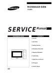
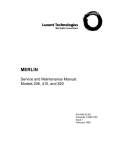
Lucent Technologies
Bell Labs Innovations
®
SPIRIT
Communications System
Model 2448
1224 Controller
Customer Installation Instructions
999-500-232
Intellectual property related to this product (including trademarks) and registered to
AT&T Corporation has been transferred to Lucent Technologies Incorporated.
Any references within this text to American Telephone and Telegraph Corporation or
AT&T should be interpreted as references to Lucent Technologies Incorporated. The
exception is cross references to books published prior to December 31, 1996, which
retain their original AT&T titles.
Lucent Technologies – formed as a result of AT&T’s planned restructuring – designs,
builds and delivers a wide range of public and private networks, communication
systems and software, consumer and business telephone systems, and microelectronic
components. The world-renowned Bell Laboratories is the research and development
arm for the company.
Table of Contents
Overview of System
Step 1 Plan Your System
Step 2 Check Outlet Grounding
Step 3 Mount Controller
Mount the Power Supply Unit
Mount Controller on Wall
Install Line and Station Cards
Test the Incoming Telephone Lines
Test the Controller
Connect Telephone Lines to Controller
Step 4 Wiring Runs
Business (4-Pair) Wiring
List of Materials
Mount Jack Panel Boxes
Run Cable to All Telephone Locations
Install Modular Connecting Blocks
Customer Convenience Wiring
List of Materials
Install Modular Plugs and Wire Junction Boxes
Secure Telephone Wire
Install Modular Connecting Blocks
Step 5 Install Telephone Sets
Record Installation Date
Desk Mount
Wall Mount
Label Intercom Extension Number
Step 6 Connect Controller to Wiring Runs
Step 7 Install Optional Equipment
Step 8 Put the Panel Back On
Step 9 Power Up the System
Troubleshooting
Service Technician Diagnostics
Controller Self Test
What Each Test Does
Repairing a Problem
Key to Indicator Lights During Controller Self Test
Replacement Parts
Interference Information; FCC Regulations
Pertaining to this Equipment
1
2
3
3
3
4
4
5
5
6
7
8
8
9
10
11
13
13
13
13
13
15
15
15
15
15
16
17
18
18
19
20
20
21
21
24
24
25
Notice: While reasonable efforts were made to ensure that the information
in this document was complete and accurate at the time of printing, AT&T
assumes no responsibility for any errors. Changes or corrections to the
information contained in this document may be incorporated into future
re-issues.
IMPORTANT SAFETY INSTRUCTIONS
SPIRIT ® Communications System - 2448 Controller/2448 Expansion Unit
The exclamation point within an equilateral triangle is
intended to alert you to the presence of important operating
and maintenance instructions in the literature accompanying
the product.
When using your telephone equipment basic safety precautions should always be
followed to reduce the risk of fire, electric shock, and injury.
1.
Read and understand all instructions.
2.
Follow all warnings and instructions marked on the product.
3.
Unplug this product from the wall outlet before cleaning. Use a damp cloth for
cleaning. Do not use liquid or aerosol cleaners.
4.
Slots and openings in the housing are provided for ventilation. To protect it
from overheating, these openings must not be blocked or covered. This product
should never be installed near or over a radiator or heat register. This product
should not be placed in a built-in installation unless proper ventilation is
provided.
This product should be operated only from the type of power source indicated
on the marking label. If you are not sure of the type of power supply to your
home or business, consult your dealer or local power company.
This product is equipped with a three wire grounding type plug. This plug will
only fit into a grounding type power outlet. This is a safety feature. If you are
unable to insert the plug into the outlet, contact your electrician to replace your
outlet. Do not defeat the safety purpose of the grounding type plug.
Do not allow anything to rest on the power cord. Do not locate this product
where the cord will be abused by persons walking on it.
Do not overload wall outlets and extension cords as this can result in the risk of
fire or electric shock.
Never push objects of any kind into this product through housing slots as they
may touch dangerous voltage points or short out parts that could result in a risk
of fire or electric shock. Never spill liquid of any kind on the product.
To reduce the risk of electric shock, do not disassemble this product. Call your
AT&T representative when service or repair work is required. Opening or
removing covers may expose you to dangerous voltages or other risks. Incorrect
reassembly may cause electric shock when the appliance is subsequently used.
5.
6.
7.
8.
9.
10.
11. Unplug this product from the wall outlet and refer servicing to qualified service
personnel under the following conditions:
●
when the power supply cord or plug is damaged or frayed.
●
if liquid has been spilled into the product.
●
if the product has been exposed to rain or water.
●
if the product has been dropped or the housing has been damaged.
●
if the product exhibits a distinct change in performance.
12.
Avoid using a telephone during an electrical storm. There may be a remote risk
of electric shock from lightning.
13.
Do not use the telephone in the vicinity of a gas leak. To report a gas leak, use
a telephone away from the area of the leak.
Basic safety precautions should always be followed when your telephone equipment is
installed.
WARNING: The SPIRIT Communications System, Model 2448 must be installed by
an AT&T service technician or a qualified installer.
WARNING: If you need to install a SPIRIT Communications System telephone in a
different building but not more than 1000 feet from the control unit, In
Range-Out of Building (IROB) protectors, AT&T Order Number 31304
(TII Model 371 or ITW Model SP69073), are required. The I R O B
protectors must be installed by an AT&T service technician or a qualified
installer. Contact your AT&T representative for additional information.
1. Never install telephone wiring during a lightning storm.
2. Never install telephone jacks in wet locations unless the jack is specifically
designed for wet locations.
3. Never touch uninsulated telephone wires or terminals unless the telephone line
has been disconnected at the network interface.
4. Use caution when installing or modifying telephone lines.
5. Do not attach the power supply cord to building surfaces.
SAVE THESE INSTRUCTIONS
Overview of System
This instruction manual will show you how to install your SPIRIT ® Communications System.
Please read the instructions carefully before beginning installation.
What You Should Find in the Boxes
With the Controller:
controller (408 configuration)
power supply unit
four 7’ line cords
System Directory Label
(attached to the back of the panel)
label sheets
Administration Manual
Customer Installation Instructions
With Each Telephone:
telephone
14’ telephone cord
designation labels and plastic strips
User Manual
Reference Card and plastic sleeve
If your network interface jack (where the telephone company lines come into your building or
office) has two lines on a single jack you should purchase a 267D adapter and a line cord
(D4BU) from your AT&T PhoneCenter store or from your authorized AT&T representative.
If you need longer line and telephone cords you should purchase them also.
Controller
Power Supply
Unit
CONTROLLER SECTION
AC Outlet
(Standard 120 VAC)
Network Interface Jack
WIRING SECTION
a jack field installed
near your control
unit location
jumper cords
plugged into the
jack field and into
the control unit
cable extending from
the jack field to each
telephone location
TELEPHONE SECTION
SPIRIT is a registered trademark of AT&T
a modular jack at the end of
each cable (telephones will be
plugged in later)
1
Step 1 Plan Your System
Draw a floor plan of your business, showing the location of the network interface jacks,
where your local telephone lines come into the building or office. Install your controller
close to these jacks. Be sure an AC outlet not controlled by a switch is available.
Show on the floor plan the location of each telephone in your system and the distances of
the wiring run from the controller to each telephone location.
Below is a sample floor plan to guide you in making your own floor plan.
NOTE: If you need to install SPIRIT Commmunications System telephones in another building,
but not more than 1000 feet from the controller, an in-range, out-of-building (IROB) protection device is required. Contact your AT&T representative and order part number 31304.
INCOMING TELEPHONE LINE
(also called Network Interface Jacks)
Set
Set
Set
Set
Set
10
11
12
13
14
30’
40’
50’
60’
30’
Set
Set
Set
Set
Set
15
16
17
18
19
75’
90’
105’
120’
45’
Set
Set
Set
Set
Set
20
21
22
23
24
100’
90’
105’
130’
150’
Set 25 170’
Set 26 115’
Set 27 100’
NOTE: Be sure cords do not cross hallways. Do not run cords inside air plenums and ducts or
along hot pipes.
Step 2 Check Outlet Grounding
Your SPIRIT Communications System control unit has been protected against AC line
and central office line voltage surges caused by lightning strikes or other power
anomalies, provided the system is properly grounded.
Using a circuit tester, check (or have checked by a qualified technician) the outlet into
which your SPIRIT system control unit will be plugged. If the circuit tester detects
any of these faults, have this corrected before installation of the control unit:
— open neutral
— open ground
— hot and ground reversed
— reversed polarity
—
hot on neutral with hot open
— open hot
If necessary, have a qualified electrician repair the electrical outlet in the manner
specified by the applicable electrical codes to prevent service interruption and continue
warranty protection. If you have two-wire outlets with no ground wire, a non-switched,
three-wire grounded outlet should be installed.
2
Step 3 Mount Controller
You will need the following to mount your controller on the wall:
●
eight screws
For drywall, tile, or masonry use size 6 to 8 x ¾ inch plastic anchors with size 6 x 1 inch
slotted screws. For wood, use size 6 x 1 inch slotted round head wood screws. These screws
are available at your local hardware store.
● 12-inch
●
ruler
flathead screwdriver
● drill
with the drill bit recommended for the type of screws
● pencil
Choose a location within five feet of the network interface jacks, where the local telephone
company lines enter the building, and within five feet of a grounded (three-prong) AC outlet
that is not controlled by a switch. The power supply unit will be plugged into this outlet and
the controller connected to the power supply unit. The controller and power supply unit must be
within six inches of each other with the power supply on the left side of the controller.
NOTE: Try to position the controller so that there is an additional two feet of free wall space to
the right to allow for future expansion.
Be sure that the controller is in a well-ventilated area with a temperature range of 40° F to
100° F, and free of excessive dust and moisture. The controller should be at least two feet
from the floor.
■ A. Mount the Power Supply Unit
Mount the power supply unit on the far left side of the chosen location, making sure it is
within five feet of a grounded AC outlet not controlled by a switch.
Drill two holes 4¼ inches apart and install two mounting screws. Loosen the screws enough to
hang the power supply unit. Mark the location of the two holes on the bottom of the unit and
remove the unit from the wall. Drill two more holes. Reinstall the power supply unit onto the
wall. Insert the two bottom mounting screws, and firmly tighten all four screws.
3
■ B. Mount Controller on Wall
If you are installing the 2448 expansion unit when you first put in your SPIRIT system,
follow the instructions provided with the expansion unit instead of those in part B.
Be sure to mount the controller within six inches of where the power cable will connect to the
power supply unit. Make two level marks 11 inches apart. Drill holes at these marks and install
two of the eight mounting screws so that the screw heads are about 3/16 inches from the wall.
NOTE: If a ruler is unavailble, the panel (front cover) can be used as a guide. Remove the panel
from the controller (see panel removal instructions in part F on page 6). Along the top edge of
the panel there are four little ribs. The two ribs closest to each edge of the panel are 11 inches apart.
Temporarily hang the controller on the mounting screws, by placing the two keyholes on the
top back of the controller on the screws and pulling down gently. Make a mark at the center
of each slot on the bottom back of the controller. Remove the controller by lifting it up and away
from the mounting screws. Drill a hole at each of the two marks. Install two more mounting
screws so that the screw heads are about 3/16” from the wall.
Place the controller on all four mounting screws and pull down. Firmly tighten the bottom
mounting screws.
Write the date on the date installed label (DATE INST:) located on the label sheet and place it
on the left side of the controller.
NOTE: The controller and power supply may be installed on a table or desktop without mounting.
Take special care to reduce the possibility of the equipment moving or falling.
■ C. Install Line and Station Cards
If you purchased additional line and/or station cards, install them in the controller following
the instructions provided with the cards.
4
■D. Test the Incoming Telephone Lines
Plug a standard telephone with a modular cord into each jack of the network interface.
Lift the receiver. If you do not hear a dial tone, these jacks do not work and you will require
service from your local telephone company.
When the telephone lines were installed, the phone number of each should have been marked
on each network interface jack. If that was not done, attach a label to each jack and write the
phone number on it. You may require help from your local telephone company to decide which
jack is for which number.
Some network interface jacks carry one line only, while some carry two. If your jacks are oneline jacks (RJ11-type), you may connect the jack directly to the controller. If your jacks carry two
lines (RJ14-type), purchase a 267D 2-line adapter and a D4BU cord.
■ E. Test the Controller
Plug the controller power cable into the matching connector on the bottom of the power
supply unit. Plug the power supply unit AC power cord into the AC outlet.
Turn on the power switch located on the bottom left of the power supply unit. A green LED
will light. If the LED does not light, make sure that the power supply unit is plugged into
a working AC outlet not controlled by a switch. If it still does not light, call your AT&T Hotline
Number or your authorized dealer.
Remove the panel from the controller by first loosening the screw located at the bottom center
of the controller. Lift the panel up and away from the controller; the screw will still be in
the panel. Remove and discard the packing material on the inside of the panel.
The Controller Self Test procedure may help you confirm that the controller, the expansion unit
(if part of the system), and the installed cards are working properly.
Plug a SPIRIT 24-button telephone directly into station jack 10.
● Press
● Lift
INTERCOM.
the receiver. You must use the receiver.
❉ 9 2448.
You should hear a confirmation tone. If you hear an error tone, hang up and start over (at
Press INTERCOM), having made sure that a 24-button telephone is plugged directly into
station jack 10. After hearing a confirmation tone, PLACE THE RECEIVER AWAY FROM
YOUR EAR.
● Dial
● Dial
9 # ❉ #.
If you hear either a busy or an error tone, hang up and start over (at Press INTERCOM), having
made sure that no one is using a telephone and that any 48-Button Attendant Adjuncts
are unplugged.
After about 20 seconds, testing will be complete and the results will be shown on a block of 15
indicator lights on the telephone (see the figure on page 24).
If the indicator light is on, that portion of the test has passed.
If the indicator light is off, that portion of the test has failed.
If the indicator light is blinking, that slot on the controller should be empty, and if it is not
empty, the test has failed.
● Hang
Up.
Turn off the power on the power supply unit. The power indicator light will go off.
If you need help, consult the troubleshooting section starting on page 19.
5
■F. Connect Telephone Lines to Controller
Remove one line cord for each incoming telephone line from the controller box. Additional
cords and longer cords up to 25’ long may be purchased at your phone store or from your
AT&T representative. LABEL EACH END OF EACH CORD WITH A LINE CORD LABEL.
Pull a line cord through the opening in the bottom rear of the controller and then hook it into
the opening in the bottom front. Plug the line cord into a modular jack on the line card of the
controller. The line jacks are numbered on the plastic frame to the left. Then plug the line
cord into the network interface jack for that number. The System Directory label is located on
the back of the panel (front cover). Fill in the telephone number of that network interface
jack. Repeat the procedure for each line.
When all the line cords are installed, remove any slack from the cords in the controller by gently
pulling down on the cords at the bottom rear of the controller. Secure the line cords to the wall
or baseboard, being careful not to pierce the cords.
NOTE: If the distance between the controller and the network interface jack is greater than 7 feet,
purchase D4CE extension cords or new (14’ and 25’ lengths) line cords.
NOTE: Business (4-pair) wiring (see part 4A on page 8) can also be used to connect telephone lines
to the controller. You will want to use Z610A adapters, one for every four lines, along with jack
panel boxes (one box holds 2 Z610A adapters). Use jumper wire to connect the network interface
to Z610A adapters and the line cord supplied to connect the adapter to the controller line jack.
6
Step 4 Wiring Runs
You may choose to wire your SPIRIT Communications System using either 4-pair business
wiring materials or 2-pair customer convenience wiring materials.
Each "run" from the controller to a telephone location should be numbered and labeled.
Materials for labeling the wiring are included with the controller. Do not skip this important step.
If you choose to wire your system with customer convenience wiring, use the labels provided
to label EACH END of EVERY wiring run. Proceed to page 13.
If you choose to use the 4-pair business wiring materials, the labeling should look like the
following:
Note to installers: The SPIRlT system requires a reversal in the station set wiring. This reversal is in the
telephone (tinsel) cord that is packed with the telephone, so all other station set wiring should be straight.
7
Step 4A Business (4-pair) Wiring
You may choose to wire your location with 4-pair business wiring to be ready for future
communications needs. The materials you will need for this installation are available from your
AT&T representative or authorized dealer.
■ List of Materials
You will need the following materials:
●
screwdriver (flathead)
●
scissors
●
drill and bits appropriate for your walls
You will also need the following kits, available from your AT&T representative or authorized dealer.
Wiring Installation Kit
Wiring run labels
Jack panel box
(Number required depends on
number of telephones. You will
need one jack panel box per six
telephones.)
TELEPHONE
LOCATION
Cable installation tool
CABLE EXTENSION KIT
(one per telephone more than 10 feet
from the control unit)
Telephone location stickers
WIRING TERMINATION KIT
(one per telephone)
Modular connecting block
100-or 200-foot length of cable
(Length depends on distance between
control unit and telephone).
Cable clip
Jumper cord
Modjack-to-modjack adapter
8
■ Mount Jack Panel Boxes
Mount the jack panel boxes near the controller, creating a "jack field." You will need one
jack panel box for every six telephones in your system. If possible, the jack field should be
two to six inches below the controller if the controller is wall-mounted.
Mounting screws for the jack panel boxes are included in the wiring installation kit. If you are
installing the boxes on a sturdy supporting structure, such as studs or cross members, attach
the boxes directly to the walls. If the walls are hollow, mount the jack panel boxes on a
board that is about two inches larger all around than the complete jack field (all the boxes
mounted together). Then, mount the board on the wall.
Mount the jack
panel box with
the screws provided
or fasteners
appropriate for
your walls.
Mesh the tongue and
groove of another jack
panel box with the first.
Mount the second box.
Black dot
Snap six modjack-to-modjack
adapters into each jack retainer.
Position the black dot on the left.
9
■ Run Cable to all Telephone Locations
Select a cable extension kit with the right length of cable (100 or 200 feet) for one cable
run. For runs over 200 feet, run a 200-foot cable, terminate it in a modular connecting
block, plug in another cable, and repeat, up to a maximum of 1000 feet.
Select a Cable Extension Kit with the right length of cable
(100 or 200 feet) for one cable run. For runs over 200 feet,
you will have to run a 200 foot cable, terminate it in a
modular connecting block, and plug in another cable. The maximim
length of any cable run is 1000 feet.
If there is no
plastic cable
loop in place,
slide a cable tie
under the two
"spiders" in
each box.
Fill out a pair of wiring
run labels with the
telephone location of the
first wiring run (for
example, W1 shop,
W2 sales, W3 RM. 105).
Attach one label inside
a jack panel door.
Save the second
label for use on a
modular connecting block.
Attach a cable clip
6 to 12 inches
below the lowest
box to support
each cable as you
run it.
Plug in the cable
connector on the right
side. Thread the cable
through the clip.
Run the cable out to the telephone location. Avoid sharp
kinks or twists. Use cable clips or staples to dress the
cable neatly along wall baseboards, molding, ect. Be
careful not to damage the cable with staples.
10
■ Install Modular Connecting Blocks
Install a modular connecting block at each telephone location
Find the modular connecting block from the Cable Extension
Kit and the cable installation tool from the Wiring
Installation Kit.
Choose the location for the connecting block according to
the figure. Cut the cable, making sure you allow at least
4 inches extra.
Fasten the cable to the connecting block as shown in steps A-K, below.
Loosen screw. Remove cover and set aside.
Use cable stripping part of cable installation
tool to remove 2 inches of cable cover.
Mount connecting block
with screws or adhesive
backing provided.
Thread cable through
center of connecting
block until 1/4 inch
of cable cover shows.
Align cable
in one of
the notches.
Mounting
holes
Adhesive
backing
Cut off loose wire ends near
plastic caps. Make sure no wires
touch each other.
Insert wires in this order left
to right:
white-blue
blue
white-orange
orange
white-green
green
white-brown
brown
Attach appropriate wiring run
label to connecting block.
Remove and save
plastic caps
Align caps and press them down
firmly until they snap in place.
Replace cover and tighten
screw.
11
Typical cable installation for one telephone location.
Cable clip
‘
Identical labels
Cable
i
TELEPHONE
LOCATION
Modular connecting block
Finish your installation by routing cables to all other telephone locations and installing
modular connecting blocks for each one. Be sure to label both ends of each cable run identically.
Route your other cables and terminate each one in a
modular connecting block. Be sure to label both ends of
each cable run identically.
Cable clip
Dress the cables neatly through the lower openings and
secure them with cable clips or ties.
12
Step 4B Wiring Run, Using Customer Convenience Wiring
Customer convenience wiring materials are available at your local phone store. Different
situations require different materials. For instance, if a telephone location is less than 25 feet
from the controller, you may choose to buy a 25’ D4BU line cord and plug one end in the
modular connecting block of the telephone and the other end in the corresponding modular
connecting block in the controller. Use telephone wire clips to secure the cord to the baseboard
and your telephone is installed.
If distances are greater than 25 feet you will want to install a wiring run (see page 14). Below is
a list of materials needed for installing a wiring run using customer convenience wiring.
■ List of Materials
● wire
junction 742B–one for each length of wire used in the "run."
● telephone
wire–packages of 50-foot length are available from your phone store.
● modular
connecting block 725A or 625A–one for every desk telephone
● modular
wall connecting block 630B–one for every telephone to be mounted on the wall.
● telephone
wire stripper 953A
● telephone
wire clips
■ Install Modular Plugs (700A4) and Wire Junction Boxes (742B)
Install a modular plug at the controller end of an appropriate length of telephone wire for
each telephone in the system.
If the distance between the controller and a telephone location requires more than one wire
length, install a wire junction (742B) between the two wires. This can be repeated up to a
maximum of 1000 feet.
■ Secure Telephone Wire
Secure telephone wire along baseboard with clips. Be careful that you do not damage the wire.
■ Install Modular Connecting Blocks
Install a modular connecting block (725A or 625A) within 14 feet of every telephone that will
be desk mounted. Install a modular connecting block for wall telephones (630B) where every
wall-mounted telephone set will be located. Follow the instructions that come with the
modular connecting blocks.
Insert wires in this order:
Customer Convenience
Wiring
Business
Wiring
Red
Green
Yellow
Black
blue
blue-white
green
green-white
13
Typical Installation Using Customer Convenience Wiring
Note to installers: The SPIRIT system requires a reversal in the station set wiring. This reversal is in the
telephone (tinsel) cord that is packed with the telephone, so all other station set wiring should be straight.
14
Step 5 Install Telephone Sets
SPIRIT telephone sets are available in 6-Button and 24-Button models. The models are
installed the same way. SPIRIT telephones are not like regular telephones and will not work if
plugged directly into the Network Interface Jacks. Regular telephones will not work if they
are plugged into the station jacks on your controller.
■ Record Installation Date
Turn the telephone over. Write the installation date on the label located on the bottom of the
set above the base.
■ Desk Mount
All telephone sets are delivered assembled for desktop use; you need only attach the handset.
To install the telephone cord on a desktop set, plug one end of the cord into the jack on
the bottom of the telephone. Run the cord through the slot on the bottom of the base so that
the cord is retained by the tabs. Plug the other end of the cord into the modular connecting
block for that location. Plug the handset cord into the handset.
■ Wall Mount
To mount a SPIRIT telephone set on the wall, remove the set base by pushing in on the center
at the top of the base and pulling the base away from the telephone. Install the base on a
630B Wall Telephone Modular connecting block. Plug one end of the telephone cord into the wall
jack. Wrap surplus cord around the tabs on the base (see picture on left). Plug the other end
of the telephone cord into the jack on the back of the telephone set. Insert the top tab of the base
into the slot at the top of the set. With one hand, push up on the center of the bottom of the base.
Swing the set into position and lock in place.
Slide out the plastic hook (see picture on right) located just above the speaker grill and turn
around so the curved section sticks up into the earpiece cradle and holds the receiver in place.
Plug the handset cord into the handset.
■ Label Intercom Extension Number
Slide out the plastic hook (see picture on right) located just above the speaker grill. Lift the
clear plastic window off the hook. Locate the designation labels from the telephone box and
tear off the ICM label. Record the intercom extension number of that telephone on the ICM label.
Place the label on the plastic hook. Lay the plastic window on the label. Holding the label
and plastic window in place, slide the plastic hook back into the telephone.
—plastic hook
15
Step 6 Connect Controller To Wiring Runs
Business (4-pair) Wiring
Following the numbers on your wiring run labels, plug one end of a jumper cord into the jack
panel box (see page 7). Then pull the cord through the controller the same way you pulled
the line cords. Now plug the jumper cord into the appropriate jack in a station card in the
controller.
When all the cords are installed, remove any slack from the cords in the controller by gently
pulling down on the cords at the bottom rear of the controller. Secure the cords to the wall or
baseboard, being careful not to pierce the cords.
Customer Convenience Wiring
Pull the controller end of the wiring run through the controller the same way you pulled the
line cords. Then, following the numbers on your wiring run labels, plug the cord into the
appropriate jack in a station card in the controller (see page 14).
When all the cords are installed, remove any slack from the cords in the controller by gently
pulling down on the cords at the bottom rear of the controller. Secure the cords to the wall or
baseboard, being careful not to pierce the cords.
16
Step 7 Install Optional Equipment.
The processor card in the main controller has jacks for the call reporting (SMDR) feature, an
external alert, and a music on hold source (see figure below).
Call Reporting (SMDR) Feature
To take advantage of the call reporting (SMDR) feature that the SPIRIT system offers, you
will need to install a printer. The black jack (labeled SMDR) on the processor card provides
easy identification of where to connect your printer.
Caution. Plugging your printer into any jack other than the black SMDR jack could damage
your printer.
Several models of serial printers are available. The AT&T 475 printer is recommended.
You will need an RS232-to-modular-jack adapter in order to install your printer. If you plan
to plug the adapter directly into the printer, you must use a 355A adapter. If you intend to
plug the adapter into an RS232 cable, you need a 355AF adapter. Both of these adapters
are available from your AT&T representative.
You will also need a D8W Mounting Cord to connect the printer to the controller. If the cord
is over 50 feet long, or if you use an adapter other than a 355A or 355AF your system may
not work (you may not be able to place or receive calls). If you do not have the correct adapter
or appropriate length cord, disconnect the printer until these are obtained.
Plug one end of the D8W cord into the modular jack end of the adapter and the other end into the
SMDR jack on the processor card (see figure below). The printer should be set according to
the following specifications:
Stop Bits: 2
Data Bits: 8
Parity: None
Speed: 1200 baud
You may also choose to install a personal computer with appropriate software or specialized
hardware to utilize the call reporting feature. Contact your AT&T representative or dealer for
additional information about these options.
■ Music on Hold, Loudspeaker Paging, External Alert, Magic on Hold.
NOTE: Users of equipment that rebroadcasts copyrighted music or other materials may be
required to obtain a license from a third party such as ASCAP or BMI.
You may want to install other optional equipment.
■ The music on hold connector requires an RCA-type phono plug from the music source. The
line level for Music-On-Hold is one volt. A volume control for the music on hold is included
above the music on hold jack on the controller.
■ A loudspeaker paging system requires connection to a line jack on the controller.
If you are interested in installing optional equipment, contact your AT&T representative or
dealer for additional information.
17
Step 8 Put the Panel Back On.
Locate and engage the bottom two hooks on the panel into the housing. Lift up until the top
two hooks on the panel engage and then pull down. Tighten the screw at the bottom of
the panel.
Step 9 Power Up the System.
Turn on the power switch located on the bottom left of the power supply unit. A green LED
will light. If the LED does not light, make sure that the power supply unit is plugged into a
working AC outlet not controlled by a switch. If it still does not light, call your AT&T Hotline
Number or your authorized dealer.
18
Troubleshooting
Your SPIRIT Communications System is designed to work effectively, but a problem may occur.
If that happens, the following checklist may be helpful in solving the problem.
✓ Is the controller properly connected to a source of AC power? The power supply must be
plugged in and turned on. The green light near the power switch should be on. Note: A large
system may have two power supplies.
✓ IS the problem isolated to one SPIRIT telephone?
1. Problems with one station may be related to system administration. Review the System
Planner to check that the system is customized as you intended.
2. If the administration is not the problem, unplug the non-working telephone, wait for
60 seconds, and then plug in a working SPIRIT telephone. If the problem disappears,
contact your AT&T representative or authorized dealer to have the telephone repaired.
3. If the problem still exists, check the wiring run by taking a working telephone to the
controller and plugging it into the station jack with the same intercom extension number
as the telephone that does not work. If the problem disappears, repair the wiring run.
4. If there is still a problem, plug the telephone into another station jack in the controller.
If the problem disappears, tell your AT&T representative or authorized dealer that you
have a bad station port. If your system is not at capacity, use one of the vacant ports
until your controller is repaired, but be sure to customize the "new" station as you want it.
✓ Is the problem on just one telephone line?
1. Problems with one line may be related to system administration. Review the System
Planner to check that the system is customized as you intended.
2. If the administration is not the problem, there might be something wrong with the
telephone line coming into your system. This can be tested by plugging a regular telephone
(NOT a SPIRIT telephone) directly into the line from your local telephone company.
This should be done at the network interface jack. If the regular telephone doesn’t work
(can’t make or answer calls) the problem is not in your system. Call your local telephone
company.
✓ Do you get special features from your local telephone company or do your lines come from
a private branch exchange (PBX) with special features? Special features from your local
telephone company or PBX may interact with your system. This may result in what appear to
be lost calls or false ringing. For example, someone might accidentally forward calls to
another number so calls never reach your system.
If your system is still not working, it is recommended that you contact your AT&T representative
or authorized dealer. Before calling, please do the following:
● Make
sure all telephones are idle and that any 48-Button Attendant Adjuncts are disconnected
from the system. If calls are in progress or an adjunct is plugged in, the following test will not
run and an error tone will be heard.
● Run
the controller self test following the instructions for the test on page 5. At the end of the
test, do not hang up the handset until you have observed the MESSAGE, HFAI, MUTE,
and SPEAKER lights. Make a note of whether each of those lights is on or off and have
the information available when you contact the hotline, or your dealer.
The remainder of this section is intended for authorized service technicians.
19
CAUTION:
● TO
REMOVE A CARD, FIRST TURN OFF THE POWER AT THE POWER SUPPLY UNIT(S).
● HANDLE
THE CARD BY THE PLASTIC FACEPLATE OR LEVERS ONLY. STATIC
DISCHARGE CAN DAMAGE THE CARDS.
●ONCE
REMOVED, CARDS SHOULD NOT BE SET ON A METAL SURFACE.
● DO
NOT TURN ON THE POWER UNTIL YOU ARE SURE ALL CARDS ARE FIRMLY
SEATED.
■ Service Technician Diagnostics
Diagnostics can be accessed only from station 10. All stations should be idle when the diagnostics
are run (no telephone calls in progress). Since the 48-button adjuncts place extra loading on
the system, all 48-button adjuncts MUST be disconnected from the system during controller self
test. This can be done by unplugging them at the adjunct or the controller. If calls are in
progress or an adjunct is plugged in, the tests will not run.
■Controller Self Test
The Controller Self Test procedure may help you confirm that the controller, the expansion unit,
and the installed cards are working properly.
Plug a 24-button SPIRIT telephone directly into station jack 10.
●
Press INTERCOM.
●
Lift the receiver.
●
Dial ❋ 9 2448.
You should hear a confirmation tone. If you hear an error tone, hang up and start over (at
Press INTERCOM), having made sure that a 24-button telephone is plugged directly into
station jack 10. After hearing a confirmation tone, PLACE THE RECEIVER AWAY FROM
YOUR EAR.
●
Dial 9 # ❋ #.
If you hear either a busy or an error tone, hang up and start over (at Press INTERCOM),
having made sure that no one is using a telephone and that any 48-button Attendant Adjuncts
are unplugged.
After about 20 seconds, testing will be complete and the results will be shown on a block of 15
indicator lights on the telephone (see page 24).
If the indicator light is on, that portion of the test has passed.
If the indicator light is off, that portion of the test has failed.
If the indicator light is blinking, that slot on the controller should be empty, and if it is not
empty, the test has failed.
● If the self test seems to run and the results are never displayed, the CPU has a fault. A
fault may lock up the system until the power is cycled.
20
■ What Each Test Does
This section gives an overview of what each test does.
●A
"ROM" test failure indicates a problem with the system CPU card read only memory.
●A
"RAM" test failure indicates a problem with the system CPU card read/write memory.
●A
"SYS" test failure indicates a problem that can’t be isolated to a specific card. The problem
is some type of short or open circuit on or between cards and the backplane. This test
requires at least one working station card and one working line card. Bus connections between
station cards are only checked if more than one station card is present. The "SYS" test
light will flash, indicating a missing test, if the system can’t find a working station-line card
pair. This will occur if the system doesn’t have a working line card.
● Failures
on lights labeled Ll, L2, L3, L4, L5, or L6 may indicate a problem with a specific line
card. Each card is tested for proper connections to a station card, conferencing audio level
control, and touch tone generator control. This test requires at least one working station card
for a valid test.
● Failures
on lights labeled S1, S2, S3, S4, S5, or S6 may indicate a problem with a specific
station card. Each card is tested for proper connections to a line card, circuit shorts, circuit
opens, and card selection. This test requires at least one working line card for a valid test.
■Repairing a Problem
The system should always be powered down when adding or removing cards.
No Stations Work
Does power cycling the system restore operation? If so, a power supply or CPU card problem
may exist. Run the controller self test for more information.
Does the system have power (main and expansion supplies)? If you suspect a power supply is
malfunctioning, try to run the main controller with the power supply from the expansion unit
(if any) or substitute a supply known to be good. The main controller will operate with the
expansion unit powered down.
If power cycling doesn’t restore operation, try to remove all cards but the first station card
(station 10) and the CPU card. If operation is restored by removing most of the cards, one of the
removed cards is suspect. Cards should be added, one at a time, until the problem is found.
If operation isn’t restored by removing cards, try a station card and CPU card known to be
good. If this doesn’t restore operation, then the main or expansion backplane may not be
functioning properly.
Some, But Not All, Stations Work
If some stations work, try to rearrange/substitute station cards and/or stations to allow operation from the non-working position. If a station card and a station known to be functional
fail to operate when installed in the non-working position, suspect the CPU card and the controller. If another station card or station works in that position, replace the defective card or
station. Use the station self test to try to diagnose the problem of a malfunctioning set.
21
Telephone SeIf Test
Your telephones may be tested by running a self test procedure at each telephone set.
Press INTERCOM.
●
● Lift
●
receiver.
Dial # ❋ #.
All of the indicator lights on the set should go ON.
● Press
any button on the telephone.
All of the indicator lights should go OFF.
● Press
any button on the set.
The telephone should ring once. The receiver and the speakerphone microphone should be ON.
Now, check the indicator lights at every button by pressing the button. You should be able to turn
ON or OFF an indicator light by pressing the button next to it. If a button does not have an
indicator light, the MESSAGE indicator light will turn ON and OFF to indicate that the button
is working.
When the SPEAKER indicator light is OFF, the handset receiver (earpiece) and the speakerphone microphone should be ON. Test by rubbing your finger over the microphone (the two
small slots next to the # key) and listen to the handset receiver. You should hear static.
● Hang
up the telephone to leave Self Test. (You can always leave Self Test at any point by
hanging up.)
After completing the Self Test by hanging up the telephone, test the speaker by pressing
INTERCOM and then SPEAKER. You should hear a dial tone.
Test the handset transmitter by lifting the receiver and dialing one digit on an outside line.
Then set the handset volume to its highest level and blow into the mouthpiece. You should hear
the blowing through the handset earpiece.
Adjunct Self Test
The adjuncts may be tested by running a self test procedure at each adjunct.
● Unplug
● With
the adjunct.
the SEND MESSAGE and CANCEL MESSAGE buttons depressed, plug in the adjunct.
All of the indicator lights on the adjunct should go ON. If they do not, self test has not
been entered, some lights are defective, or the SEND MESSAGE or CANCEL MESSAGE
buttons do not work.
● Press
any button on the adjunct. All of the indicator lights should go OFF.
● Press
any button on the adjunct. All of the indicator lights will stay OFF.
● Check
the indicator lights at every button by pressing the button. Except for SEND and
CANCEL MESSAGE, you should be able to turn ON or OFF an indicator light by pressing
the button next to it. Pressing SEND MESSAGE or CANCEL MESSAGE turns ON or OFF
the NIGHT SERVICE indicator light.
● When
22
you want to leave Self Test, unplug the adjunct.
A Line Card Failure By Itself (L1 to L6)
A single line card failure with no other failures points to a defective line card. The card should
be replaced or exchanged with one known to be good. If the new card also fails, look for a
connector or controller problem. If only one station card is in the system, the station card
may have a problem.
A Station Card Failure By Itself (S1 to S6)
A single station card failure with no other failures points to defective station card, an attendant
adjunct problem, or a wiring problem between the adjunct and controller. A short in the wiring
or station may cause a station card to fail. All sets connected to the problem card should be
disconnected at the station card and the self test should be repeated to localize the problem. A set
known to be good should be used as station 10 if the problem is on the first station card.
If the failure is on the station card, replace or exchange the card with one known to be good.
If the new card also fails, look for connector or controller problem. If only one line card is in
the system, the line card may have a problem.
A SYS Failure By Itself
A non-specific system failure by itself indicates a short between audio paths that can’t be resolved
to a specific card. The short might be on a line card, station card, controller, or a connector
(even an unused one). The best way to isolate this type of problem is to remove cards to make
a minimal system (one CPU, station and line card).
A SYS Failure With Station Card Failures
A non-specific system failure along with multiple station card failures indicates an open audio
circuit between the failed station cards. The open circuit might be on one of the station cards or
the backplane. This interconnect test only executes if more than one station card is in the system.
The problem can be isolated to a specific region of the backplane by removing and swapping cards.
Many Failures
The only way to debug a system with many test failures is to remove cards to drop back to a
minimal system.
Problems Not Detected by Diagnostics
This section describes problems not detected by the diagnostics.
Tone Failures
The diagnostics do not detect problems such as noise or incorrect tone levels. The testing will not
detect a bad call progress tone. Both call progress tones can be tested manually by using the
intercom to call your own station number. An alternating frequency error tone should be heard.
The presense of this error tone confirms the operation of the call progress tone generators.
Line Card Failures
Only part of the line card is tested.
The ring detectors are not tested. They can be tested by calling the system to make sure stations
with access to the line ring.
The LA (Line Aux) jacks have a loop current detector. This can be tested by plugging a regular
telephone into one of these jacks and going off hook. A line button light on a SPIRIT station
set should light indicating that the line is in use.
Music on Hold Failures
This can be tested by calling a second line and placing the second call on hold. The music on
hold volume control can be set while listening to this call.
23
Key To Indicator Lights During Controller Self Test
Unused
Light 22
Unused
Light 23
Unused
Light 24
Unused
Light 19
S4
Light 13
Unused
Light 20
Unused
Light 17
S5
Light 14
S1
Light 10
L4
Light 7
L1
Light 4
ROM
Light 1
S2
Light 11
L5
Light 8
L2
Light 5
RAM
Light 2
Unused
Light 21
Unused
Light 18
S6
Light 15
S3
Light 12
L6
Light 9
Unused
Light 16
L
1
S
1
L
2
S
2
Card Numbers
L S
L S C
4
4
3 3 P
U
L3
Light 6
SYS
Light 3
L
5
S
5
L
6
Replacement Parts
You may order the following SPIRIT Communicator System equipment:
Order Number
Part
3130-006A
6-Button Telephone
3130-024A
24-Button Telphone
60310A
48-Button Attendant Adjunct
60311A
2448 Expansion Unit
60312A
4-Line Expansion Card
60313A
8-Station Expansion Card
10399X
Handset
10239X
Handset Cord—6 feet
2725-OILM
Handset Cord—12 feet
10241X
Handset Cord—25 feet
10090X
Telephone Cord—7 feet
103986337
Processor
105342430
1224 Apparatus Box
105468730
Power Supply
105635437
Handset Cord—9 feet
Call: AT&T Sourcebook
Number: 1-800-451-2100
Hour: 8:00 am to 5:00 pm in all U.S. time zones.
24
.
S
6
INTERFERENCE INFORMATION
FCC REGULATIONS PERTAINING TO THIS EQUIPMENT
NOTICE
Federal Communications Commission (FCC) rules require that you be notified of the following:
FCC (Part 15)
This equipment generates, uses, and can radiate radio frequency energy and, if not installed and
used in accordance with the instructions in the installation, administration and user manuals
may cause interference to radio and television communications.
This equipment has been tested and found to comply with the limits for a Class A computing
device, pursuant to Subpart J of Part 15 of FCC Rules, which are designed to provide reasonable
protection against such interference when operated in a commercial environment.
Operation of this equipment in a residential area may cause interference with nearby radios or
television, in which case the owners (at their expense) will be required to take whatever measures
may be necessary to correct the interference.
FCC (Part 68)
This equipment is registered with the Federal Communications Commission (FCC) in accordance
with Part 68 of its Rules. The FCC requires that the manufacturer provides you with the
following information:
1. CONNECTION AND USE WITH THE NATIONWIDE TELEPHONE NETWORK
The FCC requires that you connect your telephone equipment to the nationwide telephone
network through a standard telephone network interface jack such as a USOC RJ11C.
Registered equipment may not be used with Coin Telephone Lines. Equipment may be used
with Party Lines in areas where state tariffs permit such connections and when equipment is
adaptable for such use.
2.INFORMATION FOR THE TELEPHONE COMPANY
Telephone companies will generally require the following information prior to connection of
this equipment:
A. The Facility Interface Code (FIC). The FIC for this equipment is 02LS2.
B. The quantities and USOC numbers of the required jacks.
C. The FCC registration number, AS593M-16233-KF-E, and ringer equivalence number (REN),
0.3A/0.5B. Both numbers are on the controller. The REN is useful to determine how many
devices you may connect to your telephone line and still have them ring when your telephone
line is called. In most, but not all areas, the sum of all REN’s per line should be 5 or less.
You may want to contact your local telephone company for specific information.
3. REPAIR INSTRUCTONS
If it is determined that your telephone equipment is malfunctioning, the FCC requires that it
not be used and that it be unplugged from the modular outlet until the problem has been
corrected. Repairs to this equipment can be made only by the manufacturer or its authorized
agents. For repair procedures, follow the instructions outlined under the AT&T Limited
End User Warranty.
4 . RIGHTS OF THE TELEPHONE COMPANY
If telephone equipment is causing harm to the telephone network, the telephone company may
temporarily discontinue your telephone service. If possible, they will notify you before they
interrupt service. If advance notice is not practical, you will be notified as soon as possible.
You will be given the opportunity to correct the problem, and you will be informed of your right
to file a complaint with the FCC.
Your telephone company may make changes in its facilties, equipment, operations, or
procedures that could affect the proper functioning of your equipment. If such changes are
planned, you will be notified.
5. THIS EQUIPMENT IS COMPATIBLE WITH INDUCTIVELY COUPLED HEARING AIDS.