1
User Guide
Matrix Switchers
DXP DVI Pro
DXP HDMI
DVI and HDMI Series
Digital Matrix Switchers
68-1370-01 Rev. C
09 12
Safety Instructions • English
Warning
This symbol is intended to alert the user of important operating and maintenance (servicing) instructions in the literature provided with the equipment.
Power sources • This equipment should be operated only from the power source indicated on the product. This
equipment is intended to be used with a main power system with a grounded (neutral) conductor. The third
(grounding) pin is a safety feature, do not attempt to bypass or disable it.
This symbol is intended to alert the user of the presence of uninsulated
dangerous voltage within the product’s enclosure that may present a risk of
electric shock.
Power disconnection • To remove power from the equipment safely, remove all power cords from the rear of the
equipment, or the desktop power module (if detachable), or from the power source receptacle (wall plug).
Caution
Read Instructions • Read and understand all safety and operating instructions before using the equipment.
Retain Instructions • The safety instructions should be kept for future reference.
Follow Warnings • Follow all warnings and instructions marked on the equipment or in the user information.
Avoid Attachments • Do not use tools or attachments that are not recommended by the equipment
manufacturer because they may be hazardous.
Consignes de Sécurité • Français
Ce symbole sert à avertir l’utilisateur que la documentation fournie avec le
matériel contient des instructions importantes concernant l’exploitation et la
maintenance (réparation).
Ce symbole sert à avertir l’utilisateur de la présence dans le boîtier de
l’appareil de tensions dangereuses non isolées posant des risques
d’électrocution.
Attention
Lire les instructions• Prendre connaissance de toutes les consignes de sécurité et d’exploitation avant
d’utiliser le matériel.
Conserver les instructions• Ranger les consignes de sécurité afin de pouvoir les consulter à l’avenir.
Respecter les avertissements • Observer tous les avertissements et consignes marqués sur le matériel ou
présentés dans la documentation utilisateur.
Eviter les pièces de fixation • Ne pas utiliser de pièces de fixation ni d’outils non recommandés par le
fabricant du matériel car cela risquerait de poser certains dangers.
Sicherheitsanleitungen • Deutsch
Power cord protection • Power cords should be routed so that they are not likely to be stepped on or pinched
by items placed upon or against them.
Servicing • Refer all servicing to qualified service personnel. There are no user-serviceable parts inside. To prevent
the risk of shock, do not attempt to service this equipment yourself because opening or removing covers may
expose you to dangerous voltage or other hazards.
Slots and openings • If the equipment has slots or holes in the enclosure, these are provided to prevent
overheating of sensitive components inside. These openings must never be blocked by other objects.
Lithium battery • There is a danger of explosion if battery is incorrectly replaced. Replace it only with the same or
equivalent type recommended by the manufacturer. Dispose of used batteries according to the manufacturer’s
instructions.
Avertissement
Alimentations • Ne faire fonctionner ce matériel qu’avec la source d’alimentation indiquée sur l’appareil. Ce
matériel doit être utilisé avec une alimentation principale comportant un fil de terre (neutre). Le troisième contact
(de mise à la terre) constitue un dispositif de sécurité : n’essayez pas de la contourner ni de la désactiver.
Déconnexion de l’alimentation• Pour mettre le matériel hors tension sans danger, déconnectez tous les
cordons d’alimentation de l’arrière de l’appareil ou du module d’alimentation de bureau (s’il est amovible) ou
encore de la prise secteur.
Protection du cordon d’alimentation • Acheminer les cordons d’alimentation de manière à ce que personne
ne risque de marcher dessus et à ce qu’ils ne soient pas écrasés ou pincés par des objets.
Réparation-maintenance • Faire exécuter toutes les interventions de réparation-maintenance par un
technicien qualifié. Aucun des éléments internes ne peut être réparé par l’utilisateur. Afin d’éviter tout danger
d’électrocution, l’utilisateur ne doit pas essayer de procéder lui-même à ces opérations car l’ouverture ou le
retrait des couvercles risquent de l’exposer à de hautes tensions et autres dangers.
Fentes et orifices • Si le boîtier de l’appareil comporte des fentes ou des orifices, ceux-ci servent à empêcher les
composants internes sensibles de surchauffer. Ces ouvertures ne doivent jamais être bloquées par des objets.
Lithium Batterie • Il a danger d’explosion s’ll y a remplacment incorrect de la batterie. Remplacer uniquement
avec une batterie du meme type ou d’un ype equivalent recommande par le constructeur. Mettre au reut les
batteries usagees conformement aux instructions du fabricant.
Vorsicht
Dieses Symbol soll dem Benutzer in der im Lieferumfang enthaltenen
Dokumentation besonders wichtige Hinweise zur Bedienung und Wartung
(Instandhaltung) geben.
Stromquellen • Dieses Gerät sollte nur über die auf dem Produkt angegebene Stromquelle betrieben werden.
Dieses Gerät wurde für eine Verwendung mit einer Hauptstromleitung mit einem geerdeten (neutralen) Leiter
konzipiert. Der dritte Kontakt ist für einen Erdanschluß, und stellt eine Sicherheitsfunktion dar. Diese sollte nicht
umgangen oder außer Betrieb gesetzt werden.
Dieses Symbol soll den Benutzer darauf aufmerksam machen, daß im
Inneren des Gehäuses dieses Produktes gefährliche Spannungen, die
nicht isoliert sind und die einen elektrischen Schock verursachen können,
herrschen.
Stromunterbrechung • Um das Gerät auf sichere Weise vom Netz zu trennen, sollten Sie alle Netzkabel aus der
Rückseite des Gerätes, aus der externen Stomversorgung (falls dies möglich ist) oder aus der Wandsteckdose
ziehen.
Achtung
Lesen der Anleitungen • Bevor Sie das Gerät zum ersten Mal verwenden, sollten Sie alle Sicherheits-und
Bedienungsanleitungen genau durchlesen und verstehen.
Aufbewahren der Anleitungen • Die Hinweise zur elektrischen Sicherheit des Produktes sollten Sie
aufbewahren, damit Sie im Bedarfsfall darauf zurückgreifen können.
Befolgen der Warnhinweise • Befolgen Sie alle Warnhinweise und Anleitungen auf dem Gerät oder in der
Benutzerdokumentation.
Keine Zusatzgeräte • Verwenden Sie keine Werkzeuge oder Zusatzgeräte, die nicht ausdrücklich vom
Hersteller empfohlen wurden, da diese eine Gefahrenquelle darstellen können.
Instrucciones de seguridad • Español
Este símbolo se utiliza para advertir al usuario sobre instrucciones
importantes de operación y mantenimiento (o cambio de partes) que se
desean destacar en el contenido de la documentación suministrada con los
equipos.
Este símbolo se utiliza para advertir al usuario sobre la presencia de
elementos con voltaje peligroso sin protección aislante, que puedan
encontrarse dentro de la caja o alojamiento del producto, y que puedan
representar riesgo de electrocución.
Precaucion
Leer las instrucciones • Leer y analizar todas las instrucciones de operación y seguridad, antes de usar
el equipo.
Conservar las instrucciones • Conservar las instrucciones de seguridad para futura consulta.
Obedecer las advertencias • Todas las advertencias e instrucciones marcadas en el equipo o en la
documentación del usuario, deben ser obedecidas.
Evitar el uso de accesorios • No usar herramientas o accesorios que no sean especificamente
recomendados por el fabricante, ya que podrian implicar riesgos.
安全须知 • 中文
这个符号提示用户该设备用户手册中有重要的操作和维护说明。
这个符号警告用户该设备机壳内有暴露的危险电压,有触电危险。
注意
阅读说明书
保存说明书
遵守警告 •
避免追加 •
• 用户使用该设备前必须阅读并理解所有安全和使用说明。
• 用 户应保存安全说明书以备将来使用。
用户应遵守产品和用户指南上的所有安全和操作说明。
不要使用该产品厂商没有推荐的工具或追加设备,以避免危险。
Schutz des Netzkabels • Netzkabel sollten stets so verlegt werden, daß sie nicht im Weg liegen und niemand
darauf treten kann oder Objekte darauf- oder unmittelbar dagegengestellt werden können.
Wartung • Alle Wartungsmaßnahmen sollten nur von qualifiziertem Servicepersonal durchgeführt werden. Die
internen Komponenten des Gerätes sind wartungsfrei. Zur Vermeidung eines elektrischen Schocks versuchen
Sie in keinem Fall, dieses Gerät selbst öffnen, da beim Entfernen der Abdeckungen die Gefahr eines
elektrischen Schlags und/oder andere Gefahren bestehen.
Schlitze und Öffnungen • Wenn das Gerät Schlitze oder Löcher im Gehäuse aufweist, dienen diese zur
Vermeidung einer Überhitzung der empfindlichen Teile im Inneren. Diese Öffnungen dürfen niemals von anderen
Objekten blockiert werden.
Litium-Batterie • Explosionsgefahr, falls die Batterie nicht richtig ersetzt wird. Ersetzen Sie verbrauchte Batterien
nur durch den gleichen oder einen vergleichbaren Batterietyp, der auch vom Hersteller empfohlen wird.
Entsorgen Sie verbrauchte Batterien bitte gemäß den Herstelleranweisungen.
Advertencia
Alimentación eléctrica • Este equipo debe conectarse únicamente a la fuente/tipo de alimentación eléctrica
indicada en el mismo. La alimentación eléctrica de este equipo debe provenir de un sistema de distribución
general con conductor neutro a tierra. La tercera pata (puesta a tierra) es una medida de seguridad, no
puentearia ni eliminaria.
Desconexión de alimentación eléctrica • Para desconectar con seguridad la acometida de alimentación
eléctrica al equipo, desenchufar todos los cables de alimentación en el panel trasero del equipo, o desenchufar
el módulo de alimentación (si fuera independiente), o desenchufar el cable del receptáculo de la pared.
Protección del cables de alimentación • Los cables de alimentación eléctrica se deben instalar en lugares
donde no sean pisados ni apretados por objetos que se puedan apoyar sobre ellos.
Reparaciones/mantenimiento • Solicitar siempre los servicios técnicos de personal calificado. En el interior no
hay partes a las que el usuario deba acceder. Para evitar riesgo de electrocución, no intentar personalmente la
reparación/mantenimiento de este equipo, ya que al abrir o extraer las tapas puede quedar expuesto a voltajes
peligrosos u otros riesgos.
Ranuras y aberturas • Si el equipo posee ranuras o orificios en su caja/alojamiento, es para evitar el
sobrecalientamiento de componentes internos sensibles. Estas aberturas nunca se deben obstruir con otros
objetos.
Batería de litio • Existe riesgo de explosión si esta batería se coloca en la posición incorrecta. Cambiar esta
batería únicamente con el mismo tipo (o su equivalente) recomendado por el fabricante. Desachar las baterías
usadas siguiendo las instrucciones del fabricante.
警告
电源 • 该设备只能使用产品上标明的电源。 设备必须使用有地线的供电系统供电。 第三条线
(地线)是安全设施,不能不用或跳过 。
拔掉电源 • 为安全地从设备拔掉电源,请拔掉所有设备后或桌面电源的电源线,或任何接到市电
系统的电源线。
电源线保护 • 妥善布线, 避免被踩踏,或重物挤压。
维护 • 所有维修必须由认证的维修人员进行。 设备内部没有用户可以更换的零件。为避免出现触
电危险不要自己试图打开设备盖子维修该设备。
通风孔 • 有些设备机壳上有通风槽或孔,它们是用来防止机内敏感元件过热。 不要用任何东西
挡住通风孔。
锂电池 • 不正确的更换电池会有爆炸的危险。必须使用与厂家推荐的相同或相近型号的电池。按
照生产厂的建议处理废弃电池。
FCC Class A Notice
This equipment has been tested and found to comply with the limits for a Class A digital
device, pursuant to part 15 of the FCC rules. The Class A limits provide reasonable
protection against harmful interference when the equipment is operated in a commercial
environment. This equipment generates, uses, and can radiate radio frequency energy and,
if not installed and used in accordance with the instruction manual, may cause harmful
interference to radio communications. Operation of this equipment in a residential area is
likely to cause interference; the user must correct the interference at his own expense.
NOTE: This unit was tested with shielded I/O cables on the peripheral devices. Shielded
cables must be used to ensure compliance with FCC emissions limits.
For more information on safety guidelines, regulatory compliances,
EMI/EMF compatibility, accessibility, and related topics, see the “Extron Safety
and Regulatory Compliance Guide” on the Extron website.
Specifications Availability
Product specifications are available on the Extron website, www.extron.com.
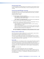
Conventions Used in this Guide
Notifications the following are used:
WARNING: Risk of severe bodily injury. A warning indicates a situation that has
the potential to result in death or severe injury.
ATTENTION: Potential Damage to Property. Attention indicates a situation that
may damage or destroy the product or associated equipment.
NOTE: A note draws attention to important information.
TIP: A tip provides a suggestion to make working with the application easier.
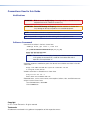
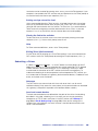
Software Commands
Commands are written in the fonts shown here:
^AR Merge Scene,,Op1 scene 1,1 ^B 51 ^W^C
[01] R 0004 00300 00400 00800 00600 [02] 35 [17] [03]
E X! *X1&* X2)* X2#* X2! CE}
NOTE: For commands and examples of computer or device responses mentioned
in this guide, the character “0” is used for the number zero and “O”
represents the capital letter “o.”
Computer responses and directory paths that do not have variables are written in the font
shown here:
Reply from 208.132.180.48: bytes=32 times=2ms TTL=32
C:\Program Files\Extron
Variables are written in slanted form as shown here:
ping xxx.xxx.xxx.xxx —t
SOH R Data STX Command ETB ETX
Selectable items, such as menu names, menu options, buttons, tabs, and field names are
written in the font shown here:
From the File menu, select New.
Click the OK button.
Copyright
© 2012 Extron Electronics. All rights reserved.
Trademarks
All trademarks mentioned in this guide are the properties of their respective owners.
Contents
Introduction............................................................ 1
About this Guide.................................................. 1
About the DXP DVI Pro and DXP HDMI Series
Digital Matrix Switchers...................................... 1
Features.............................................................. 2
DXP DVI Pro Series.......................................... 2
DXP HDMI Series............................................ 2
DXP DVI Pro and DXP HDMI............................ 2
Application Diagrams........................................... 4
Installation............................................................... 6
Rear Panels......................................................... 6
Connections........................................................ 9
Ethernet Connection........................................ 9
RS-232 and RS-422 Remote
Connections................................................. 10
Operation............................................................... 11
Definitions.......................................................... 11
Front Panel Controls and Indicators................... 12
Input and Output Buttons.............................. 13
Configuration Port......................................... 14
Control Buttons............................................. 14
I/O Buttons.................................................... 16
Button Icons.................................................. 17
Powering On..................................................... 18
Creating a Configuration.................................... 18
Example 1: Creating a Set of Ties.................. 19
Example 2: Adding a Tie to a Set of Video
Ties.............................................................. 21
Breaking Ties................................................. 22
Example 3: Removing a Tie from a Set of
Ties.............................................................. 23
Viewing a Configuration..................................... 24
Example 4: Viewing Video and Audio,
Audio-only, and Video-only Ties.................... 25
Saving and Recalling Presets............................. 28
Example 5: Saving a Preset........................... 28
Example 6: Recalling a Preset........................ 29
I/O Grouping..................................................... 31
Example 7: Grouping Inputs and Outputs...... 33
Muting and Unmuting Video and Audio
Outputs............................................................ 35
Example 8: Muting and Unmuting an
Output.......................................................... 36
Locking and Unlocking the Front Panel
(Executive Modes)............................................ 38
Selecting Lock Mode 2 or Toggling
Between Mode 2 and Mode 0...................... 38
Selecting Lock Mode 2 or Toggling
Between Mode 2 and Mode 1...................... 39
Switching from Lock Mode 1 to Lock
Mode 0......................................................... 39
Resetting........................................................... 39
Resetting the System from the Front
Panel............................................................ 39
Resetting Using the Rear Panel Reset
Button.......................................................... 40
Setting the Button Background Illumination....... 43
Selecting the RS-232/RS-422 Port Protocol
and Baud Rate (Rear Panel).............................. 43
Troubleshooting................................................. 44
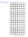
Configuration Worksheets................................. 45
Worksheet Example 1: System
Equipment.................................................... 45
Worksheet Example 2: Daily Configuration..... 46
Worksheet Example 3: Test Configuration...... 46
Worksheet Form............................................ 47
SIS Configuration and Control......................... 48
Serial Ports........................................................ 48
Ethernet Port..................................................... 49
Ethernet Cable............................................... 49
Default IP Addresses..................................... 49
Establishing an Ethernet Connection............. 49
Connection Timeouts.................................... 50
Number of Connections................................. 50
Verbose Mode............................................... 50
Host-to-Switcher Instructions............................ 50
Switcher-initiated Messages.............................. 50
DXP DVI Pro and DXP HDMI Series • Contents
v
Switcher Error Responses................................. 52
Using the Command and Response Tables
for SIS Commands........................................... 52
Special Characters........................................ 52
SIS Commands for DXP.................................... 53
Symbol Definitions......................................... 53
Command and Response Table for
DXP SIS Commands.................................... 56
IP-specific SIS Commands................................ 67
Symbol Definitions for IP-specific
Commands.................................................. 67
Command and Response Table for
IP-Specific SIS Commands........................... 69
Matrix Software.................................................... 71
Matrix Switchers Control Program..................... 71
Installing the Software.................................... 71
Software Operation Via Ethernet.................... 72
Special Characters........................................ 72
Using the Software........................................ 72
Setting Up the Matrix Window....................... 76
Managing Ties............................................... 77
IP Setup........................................................ 78
Updating the Firmware.................................. 84
Uploading HTML Files.................................... 86
Window Buttons, Menus, and Trash Can
(Right Column).............................................. 87
Window Menus............................................. 87
Using Emulation Mode................................... 98
Using the Matrix Switcher Help File.............. 100
Creating Button Labels.................................... 100
Using the Button Label Generator................ 100
Replacing Button Labels.............................. 101
Blank Button Labels.................................... 103
HTML Operation................................................ 104
Accessing the Web Pages............................... 104
Special Characters.......................................... 105
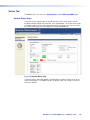
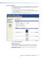
Status Tab....................................................... 106
System Status Page.................................... 106
DSVP and HDCP Page................................ 107
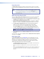
Configuration Tab............................................ 108
System Settings Page................................. 108
Passwords Page......................................... 111
Email Settings Page..................................... 112
Firmware Upgrade Page.............................. 114
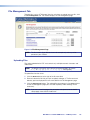
File Management Tab...................................... 116
Uploading Files............................................ 116
Adding a Directory....................................... 117
Other File Management Activities................. 117
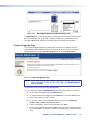
Control Tab...................................................... 118
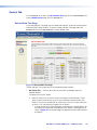
Set and View Ties Page............................... 118
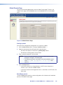
Global Presets Page.................................... 120
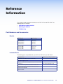
Reference Information..................................... 121
Part Numbers and Accessories....................... 121
Models........................................................ 121
Included Parts............................................. 121
Optional Accessories................................... 122
Cables and Adapters................................... 122
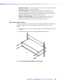
Mounting the Switcher..................................... 122
UL Guidelines for Rack Mounting................. 122
Rack Mounting Procedure........................... 123
IP Addressing.................................................. 124
What is an IP Address?............................... 124
Choosing IP Addresses............................... 124
Subnet Mask............................................... 125
Pinging for the IP Address........................... 125
Connecting as a Telnet Client....................... 126
Subnetting, a Primer.................................... 128
DXP DVI Pro and DXP HDMI Series • Contents
vi
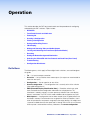
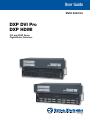
Introduction
This section gives an overview of the Extron DXP Series Digital Matrix Switchers,
describes significant features of the series, and provides application diagrams.
•
About this Guide
•
About the DXP DVI Pro and DXP HDMI Series Digital Matrix Switchers
•
Features
•
Application Diagrams
About this Guide
This guide contains installation, configuration, and operating information for the DXP
Series Digital Matrix Switchers, including the DXP DVI Pro series and the DXP HDMI
series.
The terms “DXP,“ “switcher,” and “DXP switcher” are used interchangeably in this guide to
refer to all DXP models. “DXP DVI Pro” refers to the four DVI Pro models, and “DXP HDMI”
refers to the four HDMI models.
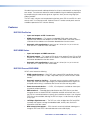
About the DXP DVI Pro and DXP HDMI Series Digital Matrix Switchers
The DXP DVI Pro and DXP HDMI series are high performance, digital matrix switchers.
The DVI Pro series route single link DVI-D signals (up to eight) and the DXP HDMI series
route HDMI signals from multiple sources to any DVI- or HDMI-equipped display devices.
All DXP matrix switchers support resolutions of up to 1920x1200 and HDTV 1080p/60.
The DVI Pro and HDMI models are HDCP compliant, enabling simultaneous distribution of
a single source signal to one or more compliant displays.
The following matrix sizes are available:
DXP DVI Pro Series:
•
DXP 44 DVI Pro: 4 inputs by 4 outputs
•
DXP 48 DVI Pro: 4 inputs by 8 outputs
•
DXP 84 DVI Pro: 8 inputs by 4 outputs
•
DXP 88 DVI Pro: 8 inputs by 8 outputs
DXP HDMI Series:
•
DXP 44 HDMI: 4 inputs by 4 outputs
•
DXP 48 HDMI: 4 inputs by 8 outputs
•
DXP 84 HDMI: 8 inputs by 4 outputs
•
DXP 88 HDMI: 8 inputs by 8 outputs
All three series provide easy integration in applications that require reliable DVI Pro or
HDMI signal routing. They include several convenience features that are common to most
Extron matrix switchers, such as the QuickSwitch Front Panel Controller (QS-FPC™),
global presets, IP Link®, and Ethernet control.
DXP DVI Pro and DXP HDMI Series • Introduction
1
All models feature automatic cable equalization for all inputs and automatic re-clocking for
each output. These features reduce the need for additional signal conditioning equipment
by compensating for weak source signals or signal loss when you are using long input
cable assemblies.
The DXP matrix switchers can be operated via the front panel, RS-232 and RS-422 serial
control, and IP Link Ethernet control. Optional Extron X-Y remote control panels are also
available to operate the DXP switcher remotely.
Features
DXP DVI Pro Series
•
Inputs and outputs on DVI-I connectors
•
HDMI signal support — Full support of embedded HDMI audio signals when
optional Extron HDMI-to-DVI adapters are used. Audio carried in the HDMI stream is
switched with the video but not removed or decoded from the data stream.
•
Automatic cable equalization for each input to 100 feet (30.4 m) at 1920x1200
when the DXP is used with Extron DVI cables
DXP HDMI Series
•
Inputs and outputs on HDMI connectors
•
DVI signal support — Full support of DVI signals when optional Extron DVI-to-HDMI
adapters are used. Audio carried in the DVI stream is switched with the video but not
removed or decoded from the data stream.
•
Automatic cable equalization for each input to 100 feet (30.4 m) at 1920x1200
when the DXP is used with Extron HDMI cables
DXP DVI Pro and DXP HDMI
All DXP series feature the following:
•
HDMI standard support — Both DXP series support HDMI specification features,
including data rates up to 6.75 Gbps, Deep Color, Lip Sync, and HD lossless audio
formats.
•
Automatic output re-clocking — Automatic output re-clocking stabilizes data to
correct pair skew and restore signal integrity for improved performance. Signals are
reshaped and the timing is restored to allow for transmission over long cables.
•
Power for external devices — +5 VDC, 250 mA power is available on the outputs
for external peripheral devices.
•
EDID reference — Extended display identification data (EDID) files let you direct
computer sources to stored EDID files that define resolution and refresh rates, or to
the EDID of a connected monitor to specify what resolution to output. User assigned
EDID files are also available, allowing the EDID of Output 1 to be manually assigned
to any input.
•
1.65 Gbps digital data rate — The DXP can switch all digital data (DVI and HDMI
standard) and supports carriage of embedded audio, ancillary data, and the ID
information of the data stream.
•
DDC transmission support — DDC channels are actively buffered, allowing passthrough of EDID and HDCP information between source and display.
DXP DVI Pro and DXP HDMI Series • Introduction
2
•
Audio breakaway — An embedded audio signal can be separated from its
corresponding video signal within the switcher, allowing the audio and video signals
from one source to be switched to different destinations
•
32 global presets — Frequently used I/O configurations can be saved and recalled
as global presets either from the front panel, IP Link, or serial control. This allows I/O
configurations to be set up and stored in memory for future use.
•
I/O mode viewing — Users can easily view which inputs and outputs are actively
connected.
•
QuickSwitch Front Panel Controller (QS-FPC) — The DXP front panels provide a
discrete button for each input and output.
•
Tri-color back-lit buttons — The front panel buttons light red, green, or amber,
depending on function, for ease of use in low-light environments, and can be custom
labeled for easy identification.
•
IP Link Ethernet control — The DXP matrix switchers can be monitored and
managed over a computer network, using standard TCP/IP protocols. IP Link
provides for remote selection of I/O ties, EDID configuration, and monitoring system
status.
•
RS-232 and RS-422 control — Using serial commands issued from the rear panel
Remote RS232/RS422 port or the front panel 2.5 mm TRS Config port, you can
control and configure the DXP switchers via the included Matrix Switchers Control
Program, or integrate the switchers into a control system. Firmware updates can also
be installed via this port.
•
Simple Instruction Set (SIS™) commands — The Extron SIS consists of a set of
basic ASCII code commands that easy programming through a control system via an
RS-232 or RS-422 connection.
•
Control software — For RS-232, RS-422, and Ethernet remote control via a
computer, the Matrix Switchers Control Program is provided with the DXP switcher.
This icon-driven software uses a graphical, drag-and-drop interface to provide
easy I/O configuration and other customization. The control software also offers an
emulation mode for configuration of an offsite switcher; the configuration can then be
saved for future downloading to the switcher.
•
Optional remote control — Available as an option is the MKP 2000 or MKP 3000
X-Y Remote Control Panel, which can be connected via Ethernet or to the Remote
RS232/RS422 port, providing the flexibility to control a DXP matrix switcher from a
remote location.
•
Front panel security lockout — Front panel lockout (executive mode) prevents
unauthorized use in non-secure environments. In lockout mode, a special button
combination is required to unlock operation of the switcher from the front panel.
•
Rack-mountable 2U, full rack width metal enclosure
•
Internal universal power supply — The 100-240 VAC, 50-60 Hz, international
power supply provides worldwide power compatibility.
•
High-bandwidth Digital Content Protection (HDCP) compliance — The DXP
switchers provide continuous authentication with HDCP-compliant input and output
devices to ensure quick and reliable switching in professional AV environments. This
enables simultaneous distribution of a single source signal to one or more displays.
The DXP switchers support full matrix switching of digital signals with HDCP for copy
protection of digital television broadcasts and high resolution digital video output from
DTV tuners, DVRs, and Blu-ray Disc players.
DXP DVI Pro and DXP HDMI Series • Introduction
3
Application Diagrams
Display 3
HDMI - HDCP COMPLIANT
POWER
12V
0.4A MAX
HDMI INPUT
6
4
1
2
7
8
5
6
HDMI OUTPUTS
3
4
7
8
LISTED
1T23
U SI.T.E.
ACT
5
3
Extron
IPL 250
IP Link Ethernet
Control Processor
RS-232
PASS THRU
ON
N/A
C
HDMI 201 Tx
DDC
REMOTE
2
REMOTE
HDMI Twisted
Pair Extender
1
LINK
LAN
Extron
HDMI 201 Tx
HDMI INPUTS
Display 8
Display 6
Display 4
RESET
Display 2
Display 7
Display 5
RS232/RS422
Display 1
1 2
1
LOCAL
2
Tx Rx
Extron
DXP HDMI Series
Extron
HDMI 201 Rx
COM 2
TX RX
INPUT
2 3 4
COM 3
TX RX
1
IR
2
RELAY
2
1
S G S G
LAN
1
3
IR
4
RELAY
3
4
S G S G
HDMI Matrix Switchers
HDMI Twisted
Pair Extender
Laptop
POWER
12V
500mA
MAX
COM1
TX RX RTS CTS
HDMI 201 Rx
POWER
12V
0.4A MAX
HDMI OUTPUT
1
2
RS-232
PASS THRU
Tx Rx
HD-VTC
TCP/IP
Network
P
L
A
Y
S
ON
T
AT
I
3
Remote User
and Administration
Control
Game Console
Document Camera
HD Satellite Receiver
Media PC Server
FULL HIGH DEFINITION 1080P VIDEO OUTPUT
PC
Blu-ray Player
HD-DVD Player
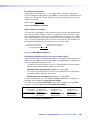
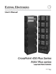
Figure 1.
Application Diagram for a DXP 88 HDMI
DXP DVI Pro and DXP HDMI Series • Introduction
4
Display 2
Display 4
DVI 201xi Tx
DVI 201xi Tx
Display 1
DO NOT CONNECT
OUTPUTS TO LAN
LOCAL MONITOR OUTPUT
DVI-D INPUT
REMOTE DDC
EDID MINDER
EDID
STORE
DEFAULT EDID
SN XXXXXXXX E XXXXX 00/00
DVI DL TX
POWER
12V
0.4A MAX
OUTPUTS
1
2
CONTROL
PASS-THRU
Tx Rx
ON ON
OFF
Display 3
1 2 3
DVI 201 Rx
INPUTS
POWER
12V
0.4A MAX
1
DO NOT
CONNECT
INPUTS
TO LAN
2
CONTROL
PASS THRU
Tx Rx
DVI-D OUTPUT
PC
DVI 201 Rx SERIES
DVI 201 Rx
TouchLink™
Control
System
DXP DVI Pro Series
DVI PRO - HDCP COMPLIANT
1
2
7
8
5
6
DVI-D OUTPUTS
3
4
7
8
LISTED
1T23
U SI.T.E.
TCP/IP
ACT
6
4
REMOTE
5
3
RS232/RS422
C
2
LINK
LAN
1
DVI-D INPUTS
RESET
HDCP-compliant DVI
Matrix Switcher
®
IPL 250
INPUT
RELAY
1
3
1
3
1
3
2
IR
4
2
4
2
4
COM
TX
1
R
RX
100
LINK
2
ACT
3
Document Camera
DVS 304 DVI
100-240V
50/60 Hz
Y
/VID
SDI
I
N
P
U
T
0.3A MAX
R-Y
B-Y
/C
RGB/R-Y,Y,B-Y/YC/VID
R
/R-Y
G
/Y
H/
HV
V
4
1
VID
2
B-Y
R-Y
3
YC
DVI-I
B
/B-Y
RS-232
O
U
T
P
U
T
Displays 5 - 8
LAN
RESET
ACT
LINK
HD Satellite Receiver
FULL HIGH DEFINITION 1080P VIDEO OUTPUT
DVD Player
HDMI-DVI Adapters
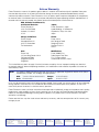
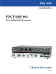
Figure 2.
Blu-ray Player
Laptop
Laptop
Application Diagram for a DXP 88 DVI Pro
DXP DVI Pro and DXP HDMI Series • Introduction
5
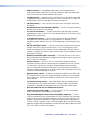
Installation
This section describes the rear panels of the DXP switchers and provides instructions for
cabling. It covers the following topics:
•
Rear Panels
•
Connections
Rear Panels
Most of the connectors are on the rear panels of the DXP switchers. The following figures
show the rear panels of a DVI model and an HDMI model.
1
3
2
4
4
1
2
7
8
5
6
DVI-D OUTPUTS
3
4
7
8
LISTED
1T23
ACT
6
3
REMOTE
5
DVI-D INPUTS
U SI.T.E.
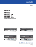
Figure 3.
RS232/RS422
C
2
LINK
LAN
1
RESET
5
DVI PRO - HDCP COMPLIANT
6
7
DXP 88 DVI Pro Rear Panel
NOTES:The illustration above shows a DXP 88 DVI Pro, with eight DVI input and
eight DVI output connectors. The rear panels of the other DVI Pro models are
identical to this model except for the number of inputs and outputs:
• DXP DVI Pro 84 – 8 inputs and 4 outputs
• DXP DVI Pro 48 – 4 inputs and 8 outputs
• DXP DVI Pro 44 – 8 inputs and 4 outputs
2
1
4
3
6
4
1
2
7
8
5
6
LISTED
1T23
U SI.T.E.
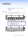
Figure 4.
3
4
7
8
ACT
5
3
REMOTE
2
RS232/RS422
C
1
HDMI OUTPUTS
LINK
LAN
HDMI INPUTS
RESET
5
HDMI - HDCP COMPLIANT
6
7
DXP 88 HDMI Rear Panel
DXP DVI Pro and DXP HDMI Series • Installation
6
NOTE: The illustration on the previous page shows a DXP 88 HDMI, with eight
HDMI input connectors and eight HDMI output connectors. The rear panels
of the other three DXP HDMI models are identical to this model except for the
number of inputs and outputs:
• DXP HDMI 84 – 8 inputs and 4 outputs
• DXP HDMI 48 – 4 inputs and 8 outputs
• DXP HDMI 44 – 4 inputs and 4 outputs
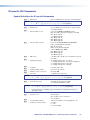
a AC power connector — Plug a standard IEC power cord into this connector to
connect the switcher to a 100 VAC to 240 VAC, 50-60 Hz power source.
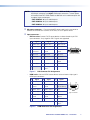
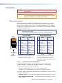
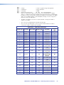
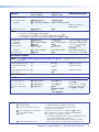
b Input connectors —
•
DVI Pro series: Connect DVI-D source devices to these female 29-pin DVI-I
input connectors. Only single-link DVI-D signals are supported.
Pin
Signal
Pin
Signal
Pin
Signal
1
TMDS data 2–
9
TMDS data 1–
17
TMDS data 0–
2
TMDS data 2+ 10 TMDS data 1+
18
TMDS data 0+
3
TMDS data
2/4 shield
11 TMDS data 1/3
shield
19
TMDS data 0/5
shield
4
Not used
12 Not used
20
Not used
5
Not used
13 Not used
21
Not used
6
DDC clock
14 +5 V power
22
TMDS clock
shield
7
DDC data
15 Ground
23
TMDS clock+
8
Not used
16 Hot plug
detect
24
TMDS clock–
Figure 5.
•
9
1
8
17
24
Female DVI Connector
DVI Connector Pin Assignments
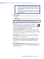
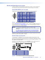
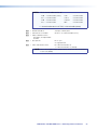
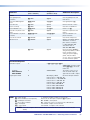
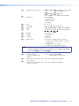
HDMI series: Connect HDMI source devices to these female 19-pin type A
HDMI input connectors.
Pin
Pin
Signal
1
TMDS data 2+
7 TMDS data 0+
13
CEC
2
TMDS data 2
shield
8
TMDS data 0
shield
14
Reserved
(NC on device)
3
TMDS data 2–
9
TMDS data 0–
15
SCL
4
TMDS data 1+ 10 TMDS clock+
16
SDA
5
TMDS data 1
shield
17
DDC/CEC
ground
6
TMDS data 1– 12 TMDS clock–
18
+5 V power
19
Hot plug
detect
Figure 6.
Pin
Signal
11 TMDS clock
shield
Signal
1
19
2
18
HDMI
Type A Connector
HDMI Connector Pin Assignments
DXP DVI Pro and DXP HDMI Series • Installation
7
NOTE:LockIt® cable lacing brackets, one for each HDMI input and output
connector, are provided with the DXP HDMI. These brackets can be
used to secure the HDMI cables to the DXP connectors to reduce
stress on the HDMI connectors and prevent signal loss due to loose
cable connections.
For information on attaching the LockIt brackets, see the LockIt HDMI
Lacing Bracket Installation Guide card, available on the Extron website
at www.extron.com.
c Output connectors —
•
DVI Pro series: Connect DVI output devices to these female 29-pin DVI-I output
connectors.
•
HDMI series: Connect HDMI output devices to these female 19-pin type A HDMI
output connectors.
to an Ethernet LAN via this RJ-45 connector. You can use a computer
to control the networked switcher with SIS commands from a remote
location. You can also control the switcher from a PC that is either running
the Matrix Switchers Control Program or via the HTML pages that are pre-loaded on
the switcher (see “Ethernet Connection” on the next page).
ACT LINK
d Ethernet port — If desired, connect the DXP switcher to a computer or
ETHERNET
NOTE: The switchers do not alter the video signal in any way. The signal that is
output by the switcher is in the same format as the input signal.
Ethernet connection indicators — The Link and Act LEDs indicate the status of
the Ethernet connection. The green Link LED indicates that the switcher is properly
connected to an Ethernet LAN. This LED should light steadily. The amber Act (Activity)
LED indicates transmission of data packets on the RJ-45 connector. This LED should
flicker as the switcher communicates.
e Reset/Power LED — This green LED remains lit while the DXP has power. It also
blinks the appropriate number of times when the unit is being reset, indicating the
level (mode) of reset that has been performed.
f Reset button — This recessed button initiates four levels (modes) of reset on the
DXP switcher. To initiate the different reset levels, use a pointed object such as a
small Philips screwdriver or a stylus to press and hold the button while the switcher
is running or while it is being powered up (see “Resetting” on page 39 for more
information).
g Remote RS232/RS422 connector — Connect a host device, such as a computer,
touch panel control, or RS-232 capable PDA to the switcher via this 9-pin D
connector for serial RS-232 and RS-422 control (see “RS-232 and RS-422 Remote
Connections” on page 10).
DXP DVI Pro and DXP HDMI Series • Installation
8
Connections
WARNING: Risk of electric shock. Remove power from the system before making
any connections.
ATTENTION: Use Electrostatic discharge precautions (be electrically grounded)
when making connections. Electrostatic discharge (ESD) can damage
equipment, although you may not feel, see, or hear it.
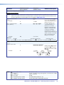
Ethernet Connection
When connecting a computer to the DXP Ethernet port, it is essential that you use the
correct Ethernet cables, and that they be properly terminated with the correct pinout.
Ethernet links use Category (CAT) 3, 5e, or 6 unshielded twisted pair (UTP) or shielded
twisted pair (STP) cables, terminated with RJ-45 connectors. Ethernet cables are limited
to a length of 328 feet (100 m).
NOTES:• Do not use standard telephone cables. Telephone cables do not support
Ethernet or Fast Ethernet.
• Do not stretch or bend the cables; this can cause transmission errors.
Crossover Cable
Pins:
12345678
Pin
Insert Twisted
Pair Wires
End 1
Wire Color
End 2
Wire Color
Pin
End 1
Wire Color
End 2
Wire Color
1
White-green
White-orange
1
White-orange
White-orange
2
Green
Orange
2
Orange
Orange
3
White-orange
White-green
3
White-green
White-green
4
Blue
Blue
4
Blue
Blue
5
White-blue
White-blue
5
White-blue
White-blue
6
Orange
Green
6
Green
Green
7
White-brown
White-brown
7
White-brown
White-brown
8
Brown
Brown
8
Brown
Brown
T568A
RJ-45
Connector
Straight-through Cable
T568B
T568B
A cable that is wired as T568A at one end
and T568B at the other (Tx and Rx pairs
reversed) is a "crossover" cable.
Figure 7.
T568B
A cable that is wired the same at both ends
is called a "straight-through" cable because
no pin or pair assignments are swapped.
Both ends of the cable can be T568B (as shown)
or T568A (not shown).
RJ-45 Connector and Pinout Tables
The cable used depends on your network speed. The switcher supports both
10 Mbps (10Base-T — Ethernet) and 100 Mbps (100Base-T — Fast Ethernet),
half-duplex and full-duplex, Ethernet connections.
•
10Base-T Ethernet requires CAT 3 UTP or STP cable at minimum.
•
100Base-T Fast Ethernet requires CAT 5e UTP or STP cable at minimum.
The Ethernet cable must be properly terminated for your application as either a crossover
or a straight-through cable.
•
Crossover cable — Direct connection between the computer and the DXP switcher
•
Patch (straight-through) cable — Connection of the DXP to a network via a router,
hub, or switch
DXP DVI Pro and DXP HDMI Series • Installation
9
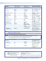
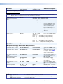
RS-232 and RS-422 Remote Connections
The DXP switchers have two serial ports through which the DXPs can be configured via
SIS commands (serial commands that control the switcher through this connector).
Remote RS232/RS422 port (rear panel)
1
6
9
5
Figure 8.
RS232/RS422
REMOTE
Figure 8 shows the pin assignments for the Remote RS232/RS422 connector.
Pin RS-232 Function
RS-422 Function
1
— Not used
—
Not used
2
Tx Transmit data
Tx– Transmit data (–)
3
Rx Receive data
Rx– Receive data (–)
4
— Not used
—
Not used
5
Gnd Signal ground
Gnd Signal ground
6
— Not used
—
Not used
7
— Not used
Rx+ Receive data (+)
8
— Not used
Tx+ Transmit data (+)
9
— Not used
—
Not used
Remote RS232/RS422 Connector Pin Assignments
See the “SIS Configuration and Control” section, starting on page 48, for definitions of
the SIS commands and the “Matrix Software” section, starting on page 71, for details
on how to install and use the control software.
NOTES:• The switcher can support either the RS-232 or RS-422 serial
communication protocol, and operate at 9600, 19200, 38400, or 115200
baud rate.
• See “Selecting the RS-232/RS-422 Protocol and Baud Rate (Rear
Panel)” on page 43 to configure this port using the front panel buttons.
If desired, you can connect an MKP 2000 or MKP 3000 remote control panel to this port.
See the user guide of either product for details.
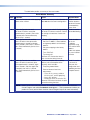
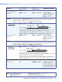
RS-232 Config port (front panel)
The Config port is an additional RS-232 connector, located on the front panel. A host
device can be connected to this port for serial RS-232 control only. Protocol for the port is
the same as for the rear panel Remote RS232/RS422 port: 9600 baud, 8 data bits, 1 stop
bit, no parity, and no flow control.
An optional 2.5 mm cable (Extron part number 70-335-01) can be used to connect the
DXP to your computer. Figure 9 shows the pin assignments for this cable.
6 feet
(1.8 m)
1
6
6
5
9
9
Part #70-335-01
Tip
Ring
9-pin D
Connection
TRS Plug
Pin 2
Pin 3
Pin 5
Computer Rx line
Computer Tx line
Computer signal ground
Tip
Ring
Sleeve
Figure 9.
Sleeve (Gnd)
2.5 mm Connector Cable for the Configuration Port
DXP DVI Pro and DXP HDMI Series • Installation
10
Operation
This section describes the DXP front panel controls and the procedures for configuring
and operating the DXP switchers. Topics include:
•
Definitions
•
Front Panel Controls and Indicators
•
Powering On
•
Creating a Configuration
•
Viewing a Configuration
•
Saving and Recalling Presets
•
I/O Grouping
•
Muting and Unmuting Video and Audio Outputs
•
Locking and Unlocking the Front Panel (Executive Modes)
•
Resetting
•
Setting the Button Background Illumination
•
Selecting the RS-232/RS-422 Port Protocol and Baud Rate (Rear Panel)
•
Troubleshooting
•
Configuration Worksheets
Definitions
The following terms, which apply to Extron digital matrix switchers, are used throughout
this guide:
•
Tie — An input-to-output connection
•
Set of ties — An input tied to two or more outputs. (An output can never be tied to
more than one input.)
•
Configuration — One or more ties or sets of ties
•
Current configuration — The configuration that is currently active in the switcher
(also called configuration 0)
•
EDID (Extended Display Identification Data) — Resolution, refresh rate, pixel
clock, and audio channel configuration information for a display device. This
information is stored in memory at system power-up and each time a new display
device is connected. The EDID is then made available to be assigned to any input.
•
Global preset — A configuration that has been stored. Up to 32 global presets can
be stored in memory. Preset locations are assigned first to the input buttons, then if
when all input buttons have presets assigned, to the output buttons. All models have
16 presets available from the front panel and 32 through RS-232/RS-422 or Ethernet.
When a preset is retrieved from memory, it becomes the current configuration.
DXP DVI Pro and DXP HDMI Series • Operation
11
•
Room — A subset of outputs that are logically related to each other, as determined
by the operator. The switchers support up to 10 rooms, each of which can consist of
1 to 16 outputs. Each room can have up to 10 presets.
•
Room preset — A configuration consisting of outputs in a single room that has
been stored. When a room preset is retrieved from memory, it becomes the current
configuration for the outputs assigned to that room only (none of the other outputs
are affected).
•
I/O Group — One of four possible subdivisions of the front panel matrix into smaller
functional sub-switchers. Inputs and outputs can be assigned to one of these groups
or not assigned to any group (see “I/O Grouping” on page 31).
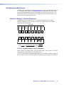
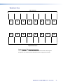
Front Panel Controls and Indicators
All models of the DXP have the same front panel with the same controls and layout. The
front panel buttons are grouped into two sets, with the input and output buttons located
on the left side of the control panel and the control buttons on the right.
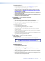
These illuminated push buttons can be labeled with text or graphics. You can set
the buttons to have amber background illumination all the time, or you can disable
the illumination (see “Setting the Button Background Illumination” on page 43).
Depending on the operation, the buttons blink or light steadily when pressed.
The front panel buttons have multiple functions. In the descriptions on the following
pages, primary functions are preceded by a square (❏) and secondary functions are
preceded by a bullet (•).
1
INPUTS
1 2 3 4 5 6 7 8
CONTROL
1 2 3 4 5 6 7 8
CONFIG
ENTER
PRESET
VIEW
I/O
ESC
VIDEO
AUDIO
OUTPUTS
DXP SERIES
DIGITAL CROSSPOINT MATRIX SWITCHER
3
2
4
5
6
7
8
9
Figure 10. DXP Switchers Front Panel
DXP DVI Pro and DXP HDMI Series • Operation
12
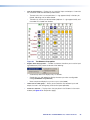
Input and Output Buttons
Each DXP model has the same number of input buttons as output buttons,
regardless of how many inputs and outputs it actually has. On models with four inputs
or outputs, buttons 5 through 8 behave like buttons 1 through 4, selecting inputs or
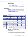
outputs 1 through 4. The following table summarizes the button functions.
Primary Functions
1
2
Action:
Select an input or output for the tie being created.
Indications:
Blinking: potential tie or untie
Lit: current tie
Amber: video and audio tie
Green: video only tie
Red: audio only tie
3
through
8
Secondary Functions
Action 1:
Input 1 and Output 1:
Select an I/O group mode.
Action 2/
indication:
Assign an input or output to the selected group.
Lit: The input or output is assigned to the selected group.
Presets
Action/
indication:
Select a preset in preset mode.
Lit: A preset has already been saved to this location.
Blinking: The preset location is selected to be saved.
Mutes
Action/
indication:
Outputs: Press and hold to mute the video, audio, or video and audio output.
Outputs, blinking: The output is muted.
Background
illumination
Action:
Press input buttons 1 and 2 to toggle between
background illumination and unlit buttons.
I/O Grouping
a Input buttons — The input buttons do the following:
Primary functions (❏):
❏ Select an input.
❏ Identify the selected input.
Secondary functions (•):
•
Input 1 only: With the Output 1 button, place the switcher in I/O grouping mode
(see “I/O Grouping” on page 31).
•
Select a global preset (see “Saving and Recalling Presets” on page 28).
•
Inputs 1 and 2 only: Toggle button background illumination on and off (see “Setting the Button Background Illumination” on page 43).
b Output buttons — The output buttons do the following:
Primary functions (❏):
❏ Select outputs.
❏ Identify the selected outputs.
DXP DVI Pro and DXP HDMI Series • Operation
13
Secondary functions (•):
•
Select a global preset (see “Saving and Recalling Presets” on page 28).
•
Output 1 only: With the Input 1 button, places the switcher in I/O grouping mode (see “I/O Grouping” on page 31).
•
Mute and unmute an output (see “Muting and Unmuting Video and Audio
Outputs” on page 35).
Configuration Port
c Config port — This RS-232 port is an alternative to the Remote RS232/RS422
connector on the DXP rear panel (see “g Remote RS232/RS422 connector”
on page 8). The Config port (RS-232 only) can be used for system configuration
and control via SIS commands or the control software. To connect to this port, see
“RS-232 Config port (front panel)” on page 10.
Control Buttons
The following table summarizes the primary and secondary functions of the four
control buttons.
Primary Functions
ENTER
PRESET
VIEW
ESC
Action:
Save changes.
Select preset
mode.
Select view
mode.
Cancel or
escape.
Indication:
Blink: Save
needed
Blink: Save preset.
Lit: Recall preset.
View the selected
mode.
Flashes once.
Select group 2.
Select group 3.
Select group 4.
Select 38400
Select 19200 baud.
baud.
Blink: Selected
Blink: Selected
Select 115200
baud.
Blink: Selected
Secondary Functions
I/O Grouping
Action/
Select group 1.
indication:
Action 1:
Port
configuration
Front panel
locks
Select Configuration Mode
Action 2/
Select 9600 baud.
indication: Blink: Selected
Action:
With Video and
Audio, select lock
mode 2 or toggle
between modes 0
and 2.
d Enter button — The Enter button does the following:
Primary functions (❏):
❏ Saves changes that you make on the front panel.
❏ Indicates that a potential tie has been created but not saved.
❏ Indicates that a global preset has been selected to be saved or recalled but that the preset action has not been accomplished.
DXP DVI Pro and DXP HDMI Series • Operation
14
Secondary functions (•):
•
In I/O grouping mode, selects group 1 (see “I/O Grouping” on page 31).
•
In I/O grouping mode, indicates that group 1 is selected.
•
With the Preset, View <, and Esc > buttons, places the switcher in serial port
configuration mode (see “Selecting the RS-232/RS-422 Protocol and Baud
Rate (Rear Panel)” on page 43).
•
Selects 9600 baud for the Remote RS232/RS422 and the RS-232 Config ports in
serial port configuration mode.
•
Indicates that the Remote RS232/RS422 and the RS-232 Config ports are set to
9600 baud in serial port configuration mode.
e Preset button — The Preset button does the following:
Primary functions (❏):
❏ Places the switcher in preset saving mode to save a configuration as a preset, and in preset recalling mode to activate a previously-defined preset.
❏ Blinks when the DXP is in preset saving mode and lights steadily when the
switcher is in preset recalling mode.
Secondary functions (•):
•
In I/O grouping mode, selects group 2.
•
In I/O grouping mode, indicates that group 2 is selected.
•
With the Enter, View <, and Esc > buttons, places the switcher in serial port
configuration mode.
•
Selects 19200 baud for the Remote RS232/RS422 and the RS-232 Config ports
in serial port configuration mode.
•
Indicates that the Remote RS232/RS422 and the RS-232 Config ports are set to
19200 baud in serial port configuration mode.
f View < button — The View < button does the following:
Primary functions (❏):
❏ Places the switcher in view-only mode to display the current configuration.
NOTE: View-only mode also provides a way to mute and unmute outputs
(see “Muting and Unmuting Video and Audio Outputs” on
page 35).
❏ Indicates that the DXP is in view-only mode.
Secondary functions (•):
•
In I/O grouping mode, selects group 3.
•
In I/O grouping mode, indicates that group 3 is selected.
•
With the Enter, Preset, and Esc > buttons, places the switcher in serial port
configuration mode.
•
Selects 38400 baud for the Remote RS232/RS422 and the RS-232 Config ports
in serial port configuration mode.
•
Indicates that the Remote RS232/RS422 and the RS-232 Config ports are set to
38400 baud in serial port configuration mode.
DXP DVI Pro and DXP HDMI Series • Operation
15
g Esc > button — The Esc > button does the following:
Primary functions (❏):
❏ Cancels operations or selections in progress and resets the front panel button indicators.
NOTE:The Esc > button does not reset the current configuration or any
presets.
❏ Indicates that the escape function has been activated (flashes once).
Secondary functions (•):
•
In I/O grouping mode, selects group 4 (see “I/O Grouping” on page 31).
•
In I/O grouping mode, indicates that group 4 is selected.
•
With the Enter, Preset, and View < buttons, selects serial port configuration mode
(see “Selecting the RS-232/RS-422 Protocol and Baud Rate (Rear Panel)”
on page 43).
•
Selects 115200 baud for the Remote RS232/RS422 and the RS-232 Config ports
in serial port configuration mode.
•
Indicates that the Remote RS232/RS422 and the RS-232 Config ports are set to
115200 baud in serial port configuration mode.
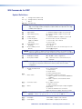
I/O Buttons
You must select video, audio, or both before creating or viewing a tie or a
configuration. This is done by pressing the Video button (h) or the Audio button (i).
Primary Functions
VIDEO
Select or deselect
video.
Green when selected
Action/indication:
AUDIO
(DXP DVI Pro and HDMI
models only) Select or
deselect audio.
Red when selected
Secondary Functions
Action 1:
With Enter, select lock mode 2 or toggle between
mode 0 and mode 2.
Action 2:
Select lock mode 1 or toggle between lock
modes 1 and 2.
Resets
Action:
Perform a system reset.
Port
configuration
Action/
Select RS-232.
indication: Blink: Selected
Front panel locks
Select RS-422.
Blink: Selected
h Video button — The Video button does the following:
Primary function (❏):
❏ Selects and deselects video for a configuration that is being created or viewed, and lights green to indicate that video is available for configuring or for viewing.
DXP DVI Pro and DXP HDMI Series • Operation
16
Secondary functions (•):
•
With the Enter button and Audio button, selects between front panel locks (lock
mode 2 and lock mode 0) (see “Locking and Unlocking the Front Panel
(Executive Modes)” on page 38).
•
With the Audio button, selects between front panel lock types (lock mode 2 and
lock mode 1).
•
With the Audio button, initiates system reset from the front panel (see “Resetting
the System from the Front Panel” on page 39).
•
Selects the RS-232 protocol for the rear panel Remote RS232/RS422 port in
serial port selection and configuration mode and indicate the selection (see
“Selecting the RS-232/RS-422 Protocol and Baud Rate (Rear Panel)” on
page 43).
i Audio button — (DXP DVI Pro and DXP HDMI only) The Audio button does the
following:
Primary function (❏):
❏ Selects and deselects audio for a configuration that is being created or viewed
and
lights red to indicate that audio is available for configuring or for viewing.
Secondary functions (•):
•
With the Enter button and the Video button, selects between front panel locks
(lock mode 2 and lock mode 0).
•
With the Video button, selects between front panel locks (lock mode 2 and lock
mode 1).
•
With the Video button, commands the front panel system reset.
•
Selects the RS-422 protocol for the rear panel Remote RS232/RS422 port in
serial port selection and configuration mode and indicate the selection.
•
Flashes to indicate that the Remote RS232/RS422 port is set to the RS-422
protocol when the DXP is in Serial Port Configuration mode.
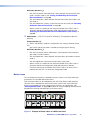
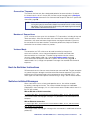
Button Icons
You can temporarily remove the numbered translucent covers on the input and output
pushbuttons to insert labels behind the covers.
Input and output labels can be created easily with the Extron Button Label Generator
software, which is provided with every Extron matrix switcher. Each input and output
button can be labeled with names, alphanumeric characters, or color bitmaps. See
“Creating Button Labels” on page 100 for details on using the labeling software and the
procedure for removing and replacing the translucent covers.
INPUTS
1
1
2
VCR
DVD
Document
Camera
Computer
5
Computer
7
VTG 200
4
5
6
7
8
OUTPUTS
Figure 11. Example of Button Labels on a DXP Front Panel
DXP DVI Pro and DXP HDMI Series • Operation
17
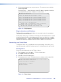
Powering On
Apply power by connecting the provided IEC power cord to the rear panel IEC connector
and to an AC source. The switcher performs a self-test that flashes the front panel
button indicators red, green, and amber and then turns them off. An error-free power-up
self-test sequence leaves all I/O and control buttons either unlit or showing background
illumination. The lit or unlit status of the Video and Audio buttons remains the same as it
was when the switcher was previously powered off.
The current configuration, EDID information, and all presets are saved in memory. When
power is applied, the most recent configuration is retrieved. The previous presets remain
intact.
If an error occurs during the self-test, the DXP locks up and does not operate. If this
occurs, call the Extron S3 Sales & Technical Support Hotline (see the last page of this
guide for contact information in your area).
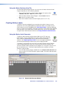
Creating a Configuration
A configuration consists of one or more inputs, each tied to a set of one or more outputs.
NOTE: While an input can be tied to multiple outputs, an output can be tied to only
one input.
This section contains the steps to follow to create or change a configuration. The following
subsections contain some examples of configurations that can be created on the DXP,
and instructions for setting them up. The illustrations show the DXP 88; however, the
procedures apply to all DXP models.
To create a configuration:
1. Press the Esc > button to clear any input, output, or control button indicators that
may be lit.
2. Select to configure video, audio, or both by pressing the
Video and Audio buttons (h and i in figure 10 on page 12).
3. Select the desired input and outputs by pressing the input and output buttons
(a and b in figure 10).
•
•
The input buttons light one of the following colors:
•
Amber: Video and audio ties
•
Green: Video only ties
•
Red: Audio only ties
Output buttons light or blink one of the following colors:
•
Amber: Video and audio ties
•
Green: Video only ties
•
Red: Audio only ties
•
To indicate potential ties, output buttons blink in the appropriate color when an
input is selected.
•
To indicate current ties, output buttons light steadily in the appropriate color
when an input is selected.
•
To clear unwanted outputs, press and release the associated lit output buttons.
To indicate potential unties, output buttons blink the appropriate color when an
output is deselected (muted) but not untied from the input.
DXP DVI Pro and DXP HDMI Series • Operation
18
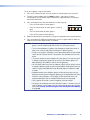
4. Press and release the Enter button to accept the tie or to break an existing tie.
5. Repeat steps 1 through 4 to create or clear additional ties until the desired
configuration is complete.
NOTES:• Only one input can be tied to an output. If you tie an input to an output that is already tied to another input, the older tie is broken in favor of the newer tie.
• If an input with no tie is selected, only the button for the selected input
lights (no output buttons light).
• If you press the input button for an I/O grouped input and then try to
select an output in a different group, the associated output button
cannot be selected, and the selected input button remains lit (see “I/O
Grouping” on page 31 for more information).
• As each input and output is selected, the associated output button
blinks the appropriate color to indicate a tentative tie. Buttons for outputs that were already tied to the input light the appropriate color
steadily. Outputs that are already tied can be left on, along with new
blinking selections, or toggled off by pressing the associated output
button.
• When the Video and Audio buttons are lit, if an input with an audio tie
but no video tie is selected, the selected input button lights amber and the output button lights the appropriate color (red, green, or amber).
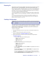
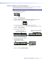
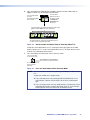
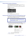
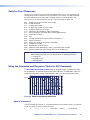
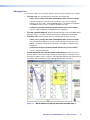
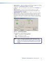
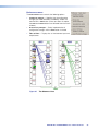
Example 1: Creating a Set of Ties
In the following example, input 5 is tied to outputs 3, 4, and 8. The steps show the front
panel indications that result from your actions.
NOTE: This example assumes that there are no ties in the current configuration.
1. Press and release the Esc > button.
Press the Esc button to clear all selections.
C O NT R O L
ENTER PRESET
VIEW
ESC
The button blinks once.
Figure 12. Clear all Selections
2. To select video and audio for the tie, press and release the Video and Audio buttons
as necessary until both the buttons light.
NOTE: Because the DXP DVI series switchers do not support audio, you cannot
create audio ties. Pressing the Audio button has no effect.
I/O
VIDEO
AUDIO
Press the Video button to toggle on and off. Press the Audio button to toggle on and off.
The button lights green when selected. The button lights red when selected.
Figure 13. Select Video and Audio
DXP DVI Pro and DXP HDMI Series • Operation
19
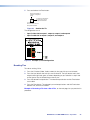
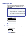
3. Press and release the Input 5 button.
Press and release the Input 5 button.
The button lights amber.
INPUTS
1
2
3
4
5
6
7
8
Figure 14. Select Input 5
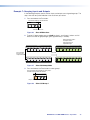
4. Press and release the Output 3, Output 4, and Output 8 buttons.
Press and release the Output 3, Output 4, and Output 8 buttons.
The buttons blink amber to indicate that the selected input will be
tied to these outputs.
CONTROL
1
2
3
4
5
6
7
8
ENTER PRESET
VIEW
ESC
OUTPUTS
The Enter button blinks
green to indicate the need to
confirm the change.
Figure 15. Select the Outputs
NOTE: You can cancel the entire set of ties at this point by pressing and releasing
the Esc > button. The Esc > button flashes red once.
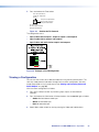
5. Press and release the Enter button.
Press the Enter button to
confirm the configuration
change.
ENTER
All input and output buttons
become unlit or return to
background illumination.
The Enter button
becomes unlit or returns to
background illumination.
Figure 16. Press Enter to Confirm the Tie
The configuration now is input 5 video and audio tied to output 3, output 4, and
output 8.
Figure 17. Example 1, Final Configuration
DXP DVI Pro and DXP HDMI Series • Operation
20
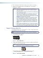
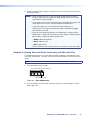
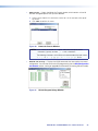
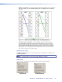
Example 2: Adding a Tie to a Set of Video Ties
In the following example, a new tie is added to the current configuration. The illustrations
show the front panel indications that result from your actions.
NOTE: This example assumes that you have performed example 1.
1. Press and release the Esc > button.
Press the Esc button to clear all selections.
C O NT R O L
ENTER PRESET
VIEW
ESC
The button blinks once.
Figure 18. Clear All Selections
2. To select only video for the tie, press and release the Video and Audio buttons as
necessary until the Video button is lit and the Audio button is off.
I/O
VIDEO
AUDIO
Press the Video button to toggle video on. Press the Audio button to toggle audio off.
The button lights green when selected. The button is unlit or background illuminated when deselected.
Figure 19. Select Video Only
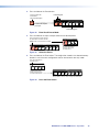
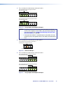
3. Press and release the Input 5 button.
The Output 3, Output 4, and Output 8 buttons
light green to indicate the video ties created in
example 1.
Press and release the Input 5 button.
The button lights green to indicate that video
outputs can be tied to or untied from this input.
INPUTS
1
2
3
4
6
5
7
1
8
2
3
4
5
6
7
8
OUTPUT
Figure 20. Select an Input with Ties
4. Press and release the Output 1 button.
Press and release the Output 1 button.
The button blinks green to indicate that the
selected video input will be tied to this output.
CONTROL
1
2
3
4
5
6
7
8
ENTER PRESET
VIEW
ESC
OUTPUT
The Enter button blinks
green to indicate the need to
confirm the change.
Figure 21. Select an Additional Output
DXP DVI Pro and DXP HDMI Series • Operation
21
5. Press and release the Enter button.
Press the Enter button to
confirm the configuration
change.
ENTER
All input and output buttons
become unlit or return to
background illumination.
The Enter button
becomes unlit or returns to
background illumination.
Figure 22. Confirm the Tie
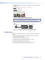
The configuration now is:
•
Input 5 video tied to output 1, output 3, output 4, and output 8
•
Input 5 audio tied to output 3, output 4, and output 8
Figure 23. Example 2, Final Configuration
Breaking Ties
To undo an existing I/O tie:
1. Press the I/O button (Video, Audio, or both) for the type of tie you want to break.
2. Press the input button whose tie you want to dissolve. The input button and its tied
output buttons light red, green, or amber, depending on your selection in step 1 and
on the types of ties the selected input currently has.
3. Press the desired lit output button. The selected output button and the Enter button
start to blink.
4. Press the Enter button. The selected input and output buttons and the Enter button
become unlit, and the tie is broken.
Example 3: Removing a Tie from a Set of Ties, on the next page, lets you practice this
procedure.
DXP DVI Pro and DXP HDMI Series • Operation
22
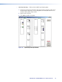
Example 3: Removing a Tie from a Set of Ties
In the following example, an existing tie is removed from the current configuration. The
steps show the front panel indications that result from your action.
NOTE: This example assumes that you have performed examples 1 and 2.
1. Press and release the Esc > button.
Press the Esc button to clear all selections.
C O NT R O L
ENTER PRESET
VIEW
ESC
The button blinks once.
Figure 24. Clear All Selections
2. To select only audio for the tie, press and release the Video and Audio buttons as
necessary until the Audio button is lit and the Video button is off.
I/O
VIDEO
AUDIO
Press the Video button to toggle video off. Press the Audio button to toggle Audio on.
The button is unlit or background illuminated The button lights red when selected.
when deselected.
Figure 25. Select Audio Only
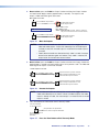
3. Press and release the input 5 button.
The Output 3, Output 4, and Output 8 buttons
light red to indicate the audio ties created in
example 1.
Press and release the Input 5 button.
The button lights red.
INPUTS
1
2
3
4
5
6
7
1
8
2
3
4
5
6
7
8
OUTPUT
The Output 1 button does not light green to indicate the
tie created in example 2 because that tie is video only.
Figure 26. Select an Input
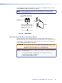
4. Press and release the Output 4 button.
Press and release the Output 4 button.
The button blinks red to indicate the pending change:
audio input will be untied.
CONTROL
1
2
3
4
5
6
7
8
ENTER PRESET
VIEW
ESC
OUTPUT
The Enter button blinks
green to indicate the need to
confirm the change.
Figure 27. Deselect the Output
DXP DVI Pro and DXP HDMI Series • Operation
23
5. Press and release the Enter button.
Press the Enter button to
confirm the configuration
change.
ENTER
All input and output buttons
become unlit or return to
background illumination.
The Enter button
becomes unlit or returns to
background illumination.
Figure 28. Confirm the Tie Removal
The configuration now is:
•
Input 5 video tied to output 1, output 3, output 4, and output 8
•
Input 5 audio tied to output 3 and output 8
•
Input 5 video and audio tied to output 3 and output 8
Figure 29. Example 3, Final Configuration
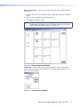
Viewing a Configuration
You can view the current set of video and audio ties using the front panel buttons. The
view-only mode prevents inadvertent changes to the current configuration. View-only
mode also provides a way to mute outputs (see “Muting and Unmuting Video and
Audio Outputs” on page 35).
View the current configuration as follows:
1. Press the Esc button to clear any remaining input, output, or control button
selections.
2. Press and release the View button. All output buttons that are not tied light as follows:
•
Amber: No tied video or audio input
•
Green: No tied video input
•
Red: No tied audio input
3. Select video, audio, or both to view by pressing the Video and Audio buttons.
DXP DVI Pro and DXP HDMI Series • Operation
24
4. Select the desired input or outputs whose ties you wish to view by pressing the input
and output buttons.
NOTES:• When you place the DXP in view-only mode, all output buttons without
ties light. Likewise, when you press an output button with no ties, all other
output buttons without ties light.
• To see all ties of the current configuration, press and release each input and
output button, one at a time, with the Video and Audio buttons lit.
• In view-only mode, you can view video and audio, video-only, or
audio-only ties. Pressing and releasing the Video or Audio button toggles
each selection on and off.
• When you view video and audio ties, the Video button is lit green and the
Audio button is lit red. After you select an input or output, the output buttons
light as follows, indicating if audio is broken away:
• Amber: Video and audio ties
• Green: Video only ties
• Red: Audio only ties
• After 30 seconds of front panel inactivity, the switcher exits view-only mode.
Example 4: Viewing Video and Audio, Audio-only, and Video-only Ties
In the following example, we view the video and audio, audio-only, and video-only ties in
the current configuration. The steps show the front panel indications that result from your
actions.
NOTE: This example assumes that you have performed examples 1, 2, and 3.
1. Press and release the Esc button.
Press the Esc button to clear all selections.
C O NT R O L
ENTER PRESET
VIEW
ESC
The button blinks once.
Figure 30. Clear All Selections
2. Press and release the View button to put the switcher in view-only mode. The View
button lights red.
DXP DVI Pro and DXP HDMI Series • Operation
25
3. To select both video and audio for viewing, press and release the Video and Audio
buttons as necessary until both are lit.
Press the Video button to
toggle video on and off.
Press the Audio button
to toggle audio on and
off.
I/O
VIDEO
The button lights green
when selected.
AUDIO
The button lights red
when selected.
Until you select an input, the buttons for all untied
outputs light amber if no video or audio inputs are tied,
green if no video inputs are tied (only audio is tied), or
red if no audio inputs are tied (only video is tied).
1
2
3
5
4
6
7
8
OUTPUTS
Figure 31. Select Video and Audio
4. Press and release the Input 5 button.
Press and release the Input 5 button.
The button lights amber.
INPUTS
1
2
3
4
5
6
7
8
The output buttons for outputs that are tied to Input 5
light the appropriate color:
Amber for audio and video ties (audio follow)
Green for video ties (video breakaway)
Red for audio ties (audio breakaway)
1
3
2
4
5
6
8
7
OUTPUTS
The buttons for outputs that are not tied to Input 5
are either unlit or background illuminated.
Figure 32. Select an Input to View
5. Press and release the Video button to deselect video.
Press the Video button to
deselect it.
The button is unlit or
background illuminated
when deselected.
I/O
VIDEO
AUDIO
The Audio button
remains lit red to
indicate that only
audio is selected.
The output buttons for outputs that are tied to Input 5 light
or blink red to indicate audio ties (audio breakaway).
1
2
3
4
5
6
7
8
OUTPUTS
The output buttons for outputs that are not tied to Input 5
are either unlit or background illuminated.
Figure 33. Deselect Video to View Only Audio Ties
DXP DVI Pro and DXP HDMI Series • Operation
26
6. Press and release the Video button to toggle it to green and the Audio button to
toggle it to either unlit or background-illuminated.
Press the Video button
to select it.
The button lights green
when selected.
Press the Audio
button to deselect it.
I/O
VIDEO
The button is unlit
or background
illuminated when
deselected.
AUDIO
The output buttons for outputs that are tied to Input 5 light
green to indicate Video ties (audio breakaway).
1
2
3
4
5
6
7
8
OUTPUTS
The output buttons for outputs that are not tied to Input 5
are either unlit or background illuminated.
Figure 34. Deselect Audio and Select Video to View Only Video Ties
If video ties are established for input 5, the output buttons light green for all video
outputs tied to input 5. If no ties are established for input 5, all output buttons return
to either unlit or background illumination.
7. Press and release the View button to exit view-only mode.
Press the View button
to exit view-only mode.
All input buttons and output buttons
return to unlit or background illumination.
VIEW
The View button returns to
unlit or background
illumination.
Figure 35. Press the View Button to Exit View-only Mode
NOTE: You can also view a set of ties by selecting a tied output. To demonstrate
this:
1.Note the number of a lit output button.
2.Press and release the unlit or background-illuminated button for an untied output. Observe that the buttons for all of the untied outputs light.
3.Press the output button that you noted previously and observe that the
selected output button, the tied input button (Input 5), and the output
buttons light for all of the outputs that are tied to the input.
DXP DVI Pro and DXP HDMI Series • Operation
27
Saving and Recalling Presets
The current configuration (0) can be saved as a preset in any one of 32 preset memory
addresses. Preset locations are assigned to the input buttons and (where necessary)
output buttons. Up to 16 presets can be selected from the front panel to be either
saved or retrieved (16 additional presets can be selected via the control software, SIS
commands, or the web pages). When a preset is retrieved from memory, it becomes the
current configuration.
NOTES:• Presets cannot be viewed from the front panel unless recalled as the current
configuration. Presets can be viewed using the Matrix Switchers Control program (see the “Matrix Software” section, beginning on
page 71, for more details).
• The current configuration and all presets are stored in non-volatile memory. When power is removed and restored, the current configuration is still active
and all presets are retained.
• When a preset is recalled, it replaces the current configuration, which is lost
unless it is also stored as a preset. The recalled preset overwrites all of the
current configuration ties in favor of the preset ties.
• All models have 32 presets; however, only up to 16 presets (the number of
front panel buttons) can be selected from the front panel. Preset numbers
greater than 16 can be accessed under serial port or Ethernet control.
Preset Preset Preset Preset Preset Preset Preset Preset
2
3
5
4
8
1
6
7
INPUTS
1
2
3
4
5
6
7
8
1
2
3
4
5
6
7
8
OUTPUTS
Preset Preset Preset Preset Preset Preset Preset Preset
9
13
10
11
12
14
15
16
NOTE: Presets 17 through 32 are available via
RS-232/RS-422 and Ethernet control only.
Figure 36. Preset Locations for All DXP Models
Example 5: Saving a Preset
In the following example, the current configuration is saved as a preset. The steps show
the front panel indications that result from your actions.
1. Press and release the Esc button.
Press the Esc button to clear all selections.
C O NT R O L
ENTER PRESET
VIEW
ESC
The button blinks once.
Figure 37. Clear All Selections
DXP DVI Pro and DXP HDMI Series • Operation
28
2. Press and hold the Preset button until it blinks (approximately 2 seconds).
Preset Assigned
Press and hold the Preset button until it blinks.
PRESET
INPUTS
PRESET
2 seconds
All buttons with assigned presets
light.
If you then save the configuration
to a lit preset number, the
configuration data at that preset
location will be overwritten.
1
2
3
4
5
6
7
8
No Preset Assigned
Figure 38. Enter Save Preset Mode
3. Press and release the input or output button for the desired preset.
C O NT R O L
Press and release the Input 1 button.
ENTER PRESET
The button blinks to indicate that this
preset number is selected but not saved.
2
4
3
5
ESC
• The Enter button blinks
INPUTS
1
VIEW
7
6
8
to indicate the need to
save the preset.
• The Preset button
continues to blink.
Figure 39. Select the Preset
4. Press and release the Enter button. The current configuration is now stored in the
selected memory location.
Press the Enter button to
save the preset.
C O NT R O L
ENTER PRESET
VIEW
All input buttons return to unlit
or background illumination.
ESC
The Enter and Preset
buttons return to unlit or
background illumination.
Figure 40. Press the Enter Button
Example 6: Recalling a Preset
In the following example, a preset is recalled to become the current configuration. The
steps show the front panel indications that result from your action.
1. Press and release the Esc button.
Press the Esc button to clear all selections.
C O NT R O L
ENTER PRESET
VIEW
ESC
The button blinks once.
Figure 41. Clear All Selections
DXP DVI Pro and DXP HDMI Series • Operation
29
2. Press and release the Preset button.
Press and release the
Preset button.
Preset Assigned
The Preset button lights.
INPUTS
2
1
PRESET
All buttons with assigned
presets light.
3
4
7
6
5
8
No Preset Assigned
Figure 42. Enter Recall Preset Mode
3. Press and release the input or output button for the desired preset.
Press and release the Input 1 button.
C O NT R O L
The button blinks to indicate that this
preset number is selected but not recalled.
ENTER PRESET
VIEW
ESC
INPUTS
1
2
3
4
5
The Enter button blinks
to indicate the need to
recall the preset.
8
7
6
Figure 43. Select the Preset
4. Press and release the Enter button. The configuration stored in the selected memory
location is now the current configuration and can be viewed in view-only mode.
Press the Enter button to
recall the preset.
C O NT R O L
ENTER PRESET
VIEW
ESC
The Enter and Preset
buttons return to unlit or
background illumination.
INPUTS
1
2
3
4
5
6
7
8
All input buttons return to unlit or background illumination.
Figure 44. Press the Enter button
DXP DVI Pro and DXP HDMI Series • Operation
30
I/O Grouping
I/O grouping is a matrix switcher feature that allows you to subdivide the front panel
control of the matrix into four smaller functional sub-switchers. Inputs and outputs can be
assigned to one of four groups or not assigned to any group.
When you are creating ties on the front panel, inputs and outputs that are assigned to a
group can be tied only to other outputs and inputs within the same group. For example,
you cannot tie an input that is assigned to group 1 to an output that is assigned to
group 2. Ungrouped inputs and outputs can be switched to outputs and inputs in any
group. Ties between groups (for example, an input in group 1 tied to an output in group 2)
can be created via SIS commands, the control software, or the web pages.
Figure 45 gives an example of input and output grouping of DVI Pro and HDMI devices on
a DXP.
INPUTS
1
2
3
4
5
6
7
8
Monitor
Editing Station
#1
1
2
3
4
5
6
7
8
2 input, 4 output
matrix
Input
7 8
OUTPUTS
Editing Station
#2
Monitor
5
6 Output
7
8
Group 3
Monitor
DVS 304 IP
Camera #1
3 input, 2 output
matrix
3 input, 2 output
matrix
Input
1 2 3
Monitor
VTR
(MPEG-2/JPEG 2000) #1
2
3
4
MENU
NEXT
IR
DVS 304
Input
4 5 6
3
Output
4
1
2 Output
Camera #3
DIGITAL VIDEO SCALER
ADJUST
1
Group 2
Group 1
Monitor
Monitor
VTR
(MPEG-2/JPEG 2000) #3
Figure 45. I/O Grouping of Incompatible Video Formats
Suggested applications for the I/O grouping feature include:
•
Segregating specific video formats to prevent an input in one video format from
being inadvertently applied to an output device that supports another video format
(see figure 45).
•
Segregating input and output devices that are in separate rooms.
•
Isolating video from being displayed on specific output devices for operational security
purposes.
I/O groups can be set up using the front panel, SIS commands via RS-232 or RS-422
control (see the “SIS Configuration and Control” section, starting on page 48), the
embedded web pages (see the “HTML Operation” section, starting on page 104), or
the Matrix Switchers Control Program via RS-232, RS-422, or IP control (see the “Matrix
Software” section starting on page 71).
DXP DVI Pro and DXP HDMI Series • Operation
31
To set up I/O groups using the front panel:
1. Press the Esc button to clear any input, output, or control buttons that may be lit.
2. To enter I/O group mode, press and hold the Input 1 and Output 1 buttons
simultaneously until the buttons light to indicate the ungrouped inputs and outputs,
then release the buttons.
3. Press and release one of the control buttons to select a group:
•
Press the Enter button to select group 1.
•
Press the Preset button to select group 2 (shown at
right).
•
Press the View button to select group 3.
•
Press the Esc button to select group 4.
C O NT R O L
ENTER PRESET
Group # 1
2
VIEW
ESC
3
4
4. Select the desired inputs and outputs to assign to the group by pressing their buttons.
5. Press and release the Video and Audio buttons to exit I/O group mode, or allow the
mode to time out after approximately 30 seconds.
NOTES:• Ties between groups (for example, an input in group 1 tied to an output in group 2) can be created under RS-232/RS-422 or Ethernet control.
• Ties that existed before I/O groups were created to include them remain in effect, even if they include inputs and outputs in different groups.
• Presets that tie inputs and outputs across group boundaries can be created
under serial or Ethernet control. These presets are selectable from the front
panel.
• An input or output can be assigned to only one group. If an input or output is already assigned to a group and you assign it to a different group, the older grouping is discarded in favor of the new grouping.
• You can break audio away from the video for a given input or output that are
assigned to different groups by pressing the Video or Audio button after you
select I/O group mode (between steps 2 and 3, above) to isolate the video
or audio.
• Audio breakaway across different groups can be confusing when you are
operating the front panel. Breakaway grouping is not displayed by the Matrix
Switchers Control Program, HTML pages, or SIS commands and is not
recommended (after they are created, breakaway ties are displayed).
• For I/O groups to function, at least two groups must be created.
• I/O groups are protected when front panel lock mode 2 is selected. You can
view the groups in lock mode 2, but you cannot change them from the front
panel (see “Locking and Unlocking the Front Panel (Executive Modes)”
on page 38).
DXP DVI Pro and DXP HDMI Series • Operation
32
Example 7: Grouping Inputs and Outputs
In the following example, several switcher inputs and outputs are assigned to groups. The
steps show the front panel indications that result from your action.
1. Press and release the Esc button.
Press the Esc button to clear all selections.
C O NT R O L
ENTER PRESET
VIEW
ESC
The button blinks once.
Figure 46. Clear All Selections
2. To enter I/O group mode, press and hold the Input 1 and Output 1 buttons until all
buttons that are not grouped light green (approximately 2 seconds).
Release the Input 1 button
and Output 1 button.
Ungrouped input and
output buttons light.
INPUTS
1
2
3
4
INPUTS
5
6
7
8
Press and hold
the Input 1 and
Output 1 buttons.
1
2
3
4
5
6
7
8
1
2
3
4
5
6
7
8
2 seconds
1
2
3
4
5
6
7
8
OUTPUTS
OUTPUTS
Figure 47. Select I/O Group Mode
3. Press and release the Enter button to select group 1.
Press and release the Enter button to select group 1.
The button lights to indicate the selection.
C O NT R O L
ENTER PRESET
Group #:
1
2
VIEW
ESC
3
4
Figure 48. Select I/O Group 1
DXP DVI Pro and DXP HDMI Series • Operation
33
4. Press and release the desired input and output buttons.
Press and release the Input 1 through Input 4 buttons.
The selected buttons light.
INPUTS
1
2
3
4
5
6
7
8
Press and release the Output 1 through Output 4 buttons.
The selected buttons light.
1
2
3
4
5
6
7
8
OUTPUTS
Figure 49. Assign Inputs and Outputs to Group 1
NOTES:• I/O groups are protected when front panel lock mode 2 is selected.
You can view the groups in lock mode 2, but you cannot change them
from the front panel (see “Locking and Unlocking the Front Panel
(Executive Modes)” on page 38).
• If front panel lock mode 2 is selected and you try to perform this step,
the button presses are ignored and the Enter, Video, and Audio buttons
flash.
5. Press and release the Preset button to select group 2.
Press and release the Preset button to select group 2.
The button lights to indicate the selection.
C O NT R O L
ENTER PRESET
Group # 1
2
VIEW
ESC
3
4
Figure 50. Select I/O Group 2
6. Press and release the desired input and output buttons.
Press and release the Input 5 through Input 8 buttons.
The selected buttons light.
INPUTS
1
2
3
4
5
6
7
8
Press and release the Output 5 through Output 8 buttons.
The selected buttons light.
1
2
3
4
5
6
7
8
OUTPUTS
Figure 51. Assign Inputs and Outputs to Group 2
DXP DVI Pro and DXP HDMI Series • Operation
34
7. Simultaneously press and release the Video and Audio buttons to exit I/O group
mode.
I/O
VIDEO
AUDIO
Press and release both buttons.
Figure 52. Deselect I/O Group Mode
NOTE: If you do not press any front panel buttons for approximately 30 seconds,
the front panel times out and the switcher exits I/O group mode.
•
Group 1 consists of inputs and outputs 1 through 4.
•
Group 2 consists of inputs and outputs 5 through 8.
•
Outputs 1, 3, 4, and 8 remain tied to input 5, because those ties were created
before the groups were formed (examples 1 through 4).
Muting and Unmuting Video and Audio Outputs
Individual outputs can be muted or unmuted as follows:
NOTES:• Mutes are protected when front panel lock mode 2 is selected. You can view
the status of the output (muted or unmuted) in lock mode 2 but you cannot
change it from the front panel (see “Locking and Unlocking the Front Panel
(Executive Modes)” on page 38).
• To enable changes to the mute settings, set the lock mode to 0.
1. Press the Esc button to clear any input, output, or control buttons that may be lit.
2. Press and release the View button.
3. Press the Video and Audio buttons as necessary to select video, audio, or both to
mute or unmute.
4. One at a time, press and hold the buttons for the desired outputs until the selected
outputs blink to indicate the mute or return to their previous state to indicate the
unmute (approximately 2 seconds).
5. Press and release the View button to return the switcher to normal operation.
NOTES:• You can mute video and audio, video-only, or audio-only outputs. Pressing and releasing the Video button and the Audio button toggles each selection
on and off.
• When the DXP enters view-only mode, the output LEDs light for all outputs without ties.
• Mutes are saved to non-volatile memory. When power is removed and
restored, the mute settings are retained.
DXP DVI Pro and DXP HDMI Series • Operation
35
Example 8: Muting and Unmuting an Output
In the following example, several switcher outputs are muted and unmuted. The steps
show the front panel indications that result from your actions.
1. Press and release the Esc button.
Press the Esc button to clear all selections.
C O NT R O L
ENTER PRESET
VIEW
ESC
The button blinks once.
Figure 53. Clear All Selections
2. Press and release the View button to enter view-only mode. The View button lights
red.
3. To select both video and audio for viewing and muting, if necessary, press and release
the Video and Audio buttons.
NOTE: This example shows the front panel indications if examples 1, 2, and 3
have been completed.
Press the Video button to
toggle video on and off.
VIDEO
The button lights green
when selected.
Press the Audio button
to toggle audio on and
off.
I/O
AUDIO
The button lights red
when selected.
Until you select an input, the buttons for all untied
outputs light amber if no inputs are tied, green if
no video inputs are tied (only audio is tied), or
red if no audio inputs are tied (only video is tied).
INPUTS
1
2
3
4
5
6
7
8
Figure 54. Select Audio Only
NOTE: Output mutes are protected when front panel lock mode 2 is selected.
You can view the mutes in lock mode 2 but you cannot change them
from the front panel (see “Locking and Unlocking the Front Panel
(Executive Modes)” on page 38).
If front panel lock mode 2 is selected and you try to perform steps 4 and
5, the actions are ignored. Set the lock mode to 0 to enable changes.
DXP DVI Pro and DXP HDMI Series • Operation
36
4. One at a time, press and hold the Output 3 button and then the Output 4 button
until each button begins to blink (approximately 2 seconds). The output 3 and
output 4 video and audio signals are muted.
Mute outputs one at a time.
3
Press and hold the Output 3 button.
2 seconds
The button blinks to indicate
that the output is muted.
Green = Video is muted.
Red = Audio is muted.
Amber = Video and audio are muted. (Amber is visible only
after you have selected the Video and Audio buttons).
NOTE: Video is muted in this example.
4
3
Press and hold the Output 4 button.
2 seconds
4
The button blinks to indicate
that the output is muted.
Figure 55. Mute the Outputs
NOTES:• If both video and audio are selected, the mute action toggles both the
video and audio outputs. If either the video output or the audio output
is already muted, the unmuted output is muted and the muted output is
unmuted.
• If both video and audio are selected and only video is muted, the output
button flashes between green and amber. If only audio is selected, the
output button flashes between red and amber.
5. One at a time, press and hold the Output 3 button and then the Output 4 button for
approximately 2 seconds until each button returns to its previous state. The video and
audio signals for outputs 3 and 4 are unmuted.
Unmute outputs one at a time.
3
Press and hold the Output 3 button.
2 seconds
3
The button returns to its previous indication
(either lit, background illuminated, or unlit)
to indicate that the output is unmuted.
4
Press and hold the Output 4 button.
2 seconds
4
The button returns to its previous indication
(either lit, background illuminated, or unlit)
to indicate that the output is unmuted.
Figure 56. Unmute the Outputs
NOTE: If both video and audio are selected, the unmute action toggles both the
video and audio outputs on and off. If either the video output or the audio
output is already unmuted, the muted output is unmuted and the unmuted
output is muted.
6. Press and release the View button to exit view-only mode.
Press the View button
to exit view-only mode.
VIEW
<
All input buttons and output buttons
return to unlit or background illumination.
The View button returns to
unlit or background
illumination.
Figure 57. Press the View Button to Exit View-only Mode
DXP DVI Pro and DXP HDMI Series • Operation
37
Locking and Unlocking the Front Panel (Executive Modes)
The matrix switchers have three levels of front panel security lock that limit the operation
of the switcher from the front panel:
•
Lock mode 0 — The front panel is completely unlocked. All front panel functions are
available.
•
Lock mode 1 — All changes are locked from the front panel (except for setting lock
mode 2). Some functions can be viewed.
•
Lock mode 2 — Basic functions are unlocked. Advanced features are locked and
can only be viewed.
Basic functions include:
•
Making ties
•
Saving and recalling presets
•
Changing lock modes
Advanced functions include:
•
Creating I/O groups
•
Setting video and audio output mutes
•
Setting the rear panel Remote RS232/RS422 port protocol and baud rate
NOTE: The switcher is shipped from the factory in lock mode 2.
Selecting Lock Mode 2 or Toggling Between Mode 2 and Mode 0
NOTE: If the switcher is in lock mode 0 or mode 1, this procedure selects mode 2.
If the switcher is in lock mode 2, this procedure selects mode 0 (unlocks the
switcher).
Toggle the lock on and off by pressing and holding the Enter, Video, and Audio buttons
simultaneously until the following buttons blink twice (approximately 2 seconds).
•
The Esc, Video, and Audio buttons blink if the DXP is now in lock mode 2.
•
The Video and Audio buttons blink if the DXP is now in lock mode 0.
Press and hold the Enter, Video, and Audio buttons
simultaneously to enable lock mode 2 or to toggle
between mode 2 and mode 0.
I/O
ENTER
VIDEO
AUDIO
I/O
2 seconds
ESC
>
VIDEO
AUDIO
The Esc, Video, and Audio buttons
blink twice to indicate mode 2.
The Video and Audio buttons blink
twice to indicate mode 0.
Release the buttons.
Figure 58. Toggle Front Panel Lock Between Mode 2 and Mode 0
DXP DVI Pro and DXP HDMI Series • Operation
38
Selecting Lock Mode 2 or Toggling Between Mode 2 and Mode 1
NOTE: If the switcher is in lock mode 0 or mode 1, this procedure selects mode 2.
If the switcher is in lock mode 2, this procedure selects mode 1.
Toggle the lock on and off by pressing and holding the Video and Audio buttons until the
following buttons blink twice (approximately 2 seconds).
•
The Esc, Video, and Audio buttons blink if the DXP is now in lock mode 2.
•
The Video and Audio buttons blink if the DXP is now in lock mode 1.
Press and hold the Video and Audio buttons
simultaneously to enable lock mode 2 or to
toggle between mode 1 and mode 2.
I/O
VIDEO
AUDIO
I/O
2 seconds
VIDEO
ESC
>
AUDIO
The Esc, Video, and Audio buttons
blink twice to indicate mode 2.
The Video and Audio buttons blink
twice to indicate mode 1.
Release the buttons.
Figure 59. Toggle Front Panel Lock Between Mode 2 and Mode 1
Switching from Lock Mode 1 to Lock Mode 0
If the switcher is in lock mode 1, you cannot change it directly to lock mode 0 (completely
unlocked. You must first place the switcher in lock mode 2, then toggle it to mode 0
(see “Selecting Lock Mode 2 or Toggling Between Mode 2 and Mode 0” on the
previous page).
Resetting
There are several methods by which you can reset the DXP, and some of these methods
allow for four levels of resetting. The following reset methods are available on the DXP:
•
Front panel buttons (See “Resetting the System from the Front Panel.”)
•
Rear panel Reset button (See “Resetting Using the Rear Panel Reset Button”
on the next page.)
•
SIS commands (See the Resets commands in the Command and Response Table
for SIS Commands, page 63.)
•
Matrix Switchers Control Software (See “Master-Reset button” on page 97.)
Resetting the System from the Front Panel
The front panel reset is identical to the E ZXXX} SIS command (see the Reset whole
switcher command in the Command and Response table for SIS Commands, page 63).
A system reset does the following:
•
Clears all ties and presets
•
Clears all video and audio mutes
•
Resets all I/O grouping
NOTE: The system reset clears most image and audio adjustments. If you want to
save these settings, use the Matrix Switchers Control Program and select
Save MATRIX settings as... from the File menu before you perform this
reset (see the “Matrix Software” section, starting on page 71).
DXP DVI Pro and DXP HDMI Series • Operation
39
To reset the switcher to the factory default settings, press and hold the Video and Audio
buttons while you apply AC power to the switcher.
NOTE: System reset does not reset the Internet protocol (IP) settings or replace
user-installed firmware.
Press and hold the Video and Audio
buttons while you apply power to the
switcher.
I/O
The buttons flash, then
become unlit.
VIDEO
AUDIO
Continue to hold the Video and Audio
buttons until all input and output buttons
return to either unlit or to background
illumination and the Video and Audio
buttons light.
Power
Release the Video and Audio buttons.
Figure 60. System Reset
Resetting Using the Rear Panel Reset Button
The rear panel has a recessed Reset button that initiates various levels of resets. For
different reset levels, press and hold the button while the switcher is running or press and
hold the button while you apply power to the switcher. Use a pointed stylus, ballpoint pen,
or small Philips screwdriver to press the button.
ATTENTION: Review the reset modes in the table on the next page carefully. Using
the wrong reset mode could result in unintended loss of flash memory
programming, port reassignment, or a controller reboot.
NOTES:• The reset modes listed in the table close all open IP and Telnet connections
and all sockets.
• The modes described in the table below are separate functions, not a
continuation from mode 1 to mode 5.
• There is no reset mode 2 for DXP.
DXP DVI Pro and DXP HDMI Series • Operation
40
The table below provides a summary of the reset modes.
Reset Modes Summary
Mode
Activation
Result
Purpose/Notes
1
Hold in the Reset button while applying Restores the factory-installed firmware. It
power to the switcher.
does not clear the current configuration.
3
Hold in the Reset button until
the Reset LED blinks once (after
approximately 3 seconds); then within
1 second press Reset momentarily
(for less than 1 second) .
Turns events on and off. During resetting, Mode 3 is useful
the Reset LED flashes two times if events for troubleshooting.
are starting or three times if events are
stopping.
4
Hold in the Reset button until the
Reset LED blinks twice (once after
approximately 3 seconds and again
after 6 seconds); then within 1 second
press Reset momentarily (for less than
1 second).
• Enables ARP capability.
• Sets the IP address, subnet address,
and gateway address to the factory
defaults.
• Sets port mapping to the factory
default.
• Turns DHCP off.
• Turn events off.
Mode 1 can be
used to remove a
version of firmware
if incompatibility
issues arise.
Mode 4 enables
you to set
IP address
information using
ARP and the MAC
address.
It does not replace
any user-installed
firmware.
The Reset LED flashes four times in
quick succession during the reset.
5
Hold in the Reset button until the
Reset LED blinks three times (once
after approximately 3 seconds, again
after 6 seconds, and then again after
9 seconds); then within 1 second
press Reset momentarily (for less than
1 second).
Performs a complete reset to factory
defaults (with the exception of the
firmware), which includes:
• Everything mode 4 does
• Reset of almost all real time
adjustments:
Mode 5 is useful
if you want to
start over with
configuration and
uploading and also
to replace events.
Clears all ties, presets, audio or
RS-232 mutes, and I/O grouping.
• Resets all IP options.
• Removes or clears all switcher files.
The reset LED flashes four times in quick
succession during the reset.
•
NOTE: Mode 5 reset clears most adjustments. To save these settings, use the Matrix Switchers
Control Program and select Save MATRIX settings as... from the File menu before you
perform this reset (see the Matrix Switcher Control Program help file for more information).
DXP DVI Pro and DXP HDMI Series • Operation
41
To perform a soft reset of the switcher:
1. Use a small Philips screwdriver to press and hold the rear panel Reset button until
the front panel Video and Audio buttons blink once (for an events reset), twice (for a
system reset), or three times (for an absolute reset).
Release, then immediately
press and release again.
RESET
RESET
Events Reset
(Mode 3)
Reset LED flashes once.
3 seconds
RESET
Press and hold
the Reset button.
Front panel I/O buttons flash once.
I/O
VIDEO
Reset LED flashes twice.
Release, then immediately
press and release again.
6 seconds
RESET
RESET
IP Settings
Reset
(Mode 4)
RESET
Press and hold
the Reset button.
AUDIO
Front panel I/O buttons flash twice.
I/O
AUDIO
RESET
Absolute Reset
(Mode 5)
Release, then immediately
press and release again.
RESET
Reset LED flashes
three times.
Press and hold
the Reset button.
9 seconds
RESET
VIDEO
Front panel I/O buttons flash three times.
I/O
VIDEO
AUDIO
Figure 61. Soft Resets
2. Release the Reset button and then immediately press and release the Reset button
again. Nothing happens if the second momentary press does not occur within
1 second.
DXP DVI Pro and DXP HDMI Series • Operation
42
Setting the Button Background Illumination
The buttons on the front panel can be set to have amber background illumination at all
times or the background illumination can be turned off.
To toggle the background illumination on and off, press and hold the Input 1 and Input 2
buttons simultaneously until the button background illumination changes (approximately
2 seconds.
Press and hold the Input 1 and Input 2 buttons
simultaneously to toggle background illumination
mode on or off.
INPUTS
1
2
3
4
5
6
7
8
1
2
3
4
5
6
7
8
OUTPUTS
After approximately 2 seconds, release
the Input 1 and Input 2 buttons.
Figure 62. Toggle Background Illumination On or Off
Selecting the RS-232/RS-422 Port Protocol and Baud Rate (Rear Panel)
The DXP switchers can support either RS-232 or RS-422 serial communication protocol,
and can operate at 9600, 19200, 38400, and 115200 baud rates. The settings of these
variables can be viewed and changed from the front panel.
NOTE: • The Remote RS232/RS422 port settings are protected when front panel lock
mode 2 is selected. You can view the settings in lock mode 2 but you cannot
adjust them from the front panel (see “Locking and Unlocking the Front
Panel (Executive Modes)” on page 38).
• To enable changes to the RS-232 or RS-422 settings, set the lock mode to
0.
View and configure the switcher serial communications settings as follows:
1. To enter serial port configuration mode, simultaneously press and hold all four control
buttons (Enter, Preset, View, and Esc) until they all light, with one flashing.
Press and hold the Enter, Preset,
View, and Esc buttons.
C O NT R O L
ENTER PRESET
VIEW
I/O
C O NT R O L
ESC
2 seconds
ENTER PRESET
VIEW
ESC
All Control buttons light with
one flashing.
VIDEO
AUDIO
Both I/O buttons light
with one flashing.
The Control button that continues flashing indicates the baud rate
as follows:
Enter — 9600
Preset — 19200
View — 38400
Esc — 115200
The I/O button that continues flashing indicates the protocol as
follows:
Video — RS-232
Audio — RS-422
In this example, the port is set to RS-232 at 9600 baud.
Figure 63. RS-232 or RS-422 Baud Rate Display
2. Release the Control buttons.
DXP DVI Pro and DXP HDMI Series • Operation
43
3. To change a value, press and release the button that selects the desired value (see
figure 64).
Press and release the buttons to configure the RS-232/RS-422 port as follows:
Baud rate:
Enter — 9600
Preset — 19200
View — 38400
Esc — 115200
Serial protocol:
Video — RS-232 Audio — RS-422
The selected buttons blink and the others remain lit.
In this example, the port is set to RS-422 at 38400 baud.
I/O
C O NT R O L
ENTER PRESET
VIEW
ESC
VIDEO
AUDIO
Figure 64. RS-232/RS-422 and Baud Rate Selection
NOTE: If front panel lock mode 2 is selected and you try to perform this step, the
actions are ignored and the Enter, Video, and Audio buttons flash.
4. Press and release any input or output button to exit the serial port configuration
mode.
Press and release an
input or output button.
5
All Control and I/O buttons return to unlit or background illumination.
I/O
CONTROL
ENTER PRESET
VIEW
ESC
VIDEO
AUDIO
Figure 65. Exit Serial Port Selection and Configuration mode
Troubleshooting
Following are recommendations for actions to take if you have problems operating the
switcher:
1. Ensure that all devices are plugged in and powered on. The switcher is receiving
power if the Reset/Power LED is lit.
2. Check to see if one or more outputs are muted.
3. Ensure that an active input is selected for output on the switcher.
4. Ensure that the proper signal format is supplied.
5. Check the cabling and make corrections as necessary.
6. Call the Extron S3 Sales & Technical Support Hotline if necessary.
DXP DVI Pro and DXP HDMI Series • Operation
44
Configuration Worksheets
Instead of trying to remember the configuration for each preset, use worksheets to record
this information. Make copies of the blank worksheet on page 47, and use one sheet
for each preset configuration. Cross out all unused or inactive inputs and outputs. The
worksheet is generic for all models of DXP. Disregard or cross out boxes for inputs and
outputs that your switcher does not have.
Worksheet Example 1: System Equipment
Figure 66 shows a worksheet for a DXP in a fictional organization with the system
hardware annotated. Output 7 has no connection in this organization, so it has been
crossed out on the worksheet.
Input Sources
DVI PRO/ DVI PRO/ DVI PRO/
HDMI
HDMI
HDMI
Camera
Camera #1 Camera
#2
#3
Main
podium
VTR
#1
VTR
#2
VTG
400DVI
Editing
Station
#1
Editing
Station
#2
1
2
3
4
5
6
7
8
1
2
3
4
5
6
7
8
Main hall
#1
Main hall
#2
Podium
monitor
#1
Conf.
Room
Podium
monitor
#2
Demo
Room
Lobby
monitor
Output Destinations
Preset #
3
Title: Weekly status mtg Video ties:
Fill in the preset number and use colors, dashes, and so forth to make connecting lines.
Figure 66. Worksheet Example 1: System Equipment
Inputs include VTRs, editing stations, DVI Pro/HDMI cameras, and an Extron VTG 400DVI.
Output devices include various DVI Pro/HDMI monitors.
The VTG 400DVI video test generator connected to input 6 enables a video test pattern to
be sent to one, several, or all output devices for problem isolation or adjustment purposes.
DXP DVI Pro and DXP HDMI Series • Operation
45
Worksheet Example 2: Daily Configuration
Figure 67 continues from worksheet example 1 by showing the video ties that make up
the configuration of preset 1. A solid ink line shows video ties.
Input Sources
DVI PRO/ DVI PRO/ DVI PRO/
HDMI
HDMI
HDMI
Camera
Camera #1 Camera
#2
#3
Main
podium
1
2
3
VTR
#1
VTR
#2
VTG
400DVI
Editing
Station
#1
Editing
Station
#2
4
5
6
7
8
7
1
2
3
4
5
6
Main hall
#1
Main hall
#2
Podium
monitor
#1
Conf.
Room
Podium
monitor
#2
Demo
Room
8
Lobby
monitor
Output Destinations
3
Preset #
Title: Daily configuration Video ties:
Fill in the preset number and use colors, dashes, and so forth to make connecting lines.
Figure 67. Worksheet Example 2: Daily Configuration
In this example:
•
The image of the presenter, from the main podium camera (input 1), is:
•
•
Displayed in the main hall (output 1)
•
Displayed in the conference room (output 4) to the overflow crowd
•
Displayed in the lobby (output 8)
•
Displayed in the Demo Room (output 6)
The presenter has a presentation stored in the VTR (input 4) that is:
•
Displayed in the main hall (output 2)
•
Displayed locally on the #1 podium (output 3).
Worksheet Example 3: Test Configuration
The AV system in our fictional organization needs to be fine tuned on a regular basis.
Figure 68 shows a typical test configuration, with an Extron video test generator (input 6)
generating a test pattern to all monitors (outputs 1, 2, 3, 4, and 8).
Input Sources
DVI PRO/ DVI PRO/ DVI PRO/
HDMI
HDMI
HDMI
Camera
Camera #1 Camera
#2
#3
Main
podium
VTR
#1
VTR
#2
VTG
400DVI
Editing
Station
#1
Editing
Station
#2
1
2
3
4
5
6
7
8
1
2
3
4
5
6
7
8
Main hall
#1
Main hall
#2
Podium
monitor
#1
Conf.
Room
Podium
monitor
#2
Demo
Room
Lobby
monitor
Output Destinations
Preset #
3
Title:
System Test
Video ties:
Fill in the preset number and use colors, dashes, and so forth to make connecting lines.
Figure 68. Worksheet Example 3: Test Configuration
DXP DVI Pro and DXP HDMI Series • Operation
46
Worksheet Form
Input Sources
1
2
3
4
5
6
7
8
1
2
3
4
5
6
7
8
Output Destinations
Preset #
Title:
Fill in the preset number and use colors, dashes, and so forth to make connecting lines.
Disregard or cross out the input and output boxes that do not apply to your switcher.
DXP DVI Pro and DXP HDMI Series • Operation
47
SIS Configuration
and Control
This section describes the serial and Ethernet connections through which the Extron
Simple Instruction Set (SIS) commands can be issued, and lists the commands that are
available for controlling and configuring the DXP switchers. Topics include:
•
Serial Ports
•
Ethernet Port
•
Host to Switcher Instructions
•
Switcher-initiated Messages
•
Switcher Error Responses
•
Using the Command and Response Tables for SIS Commands
•
SIS Commands for DXP
•
IP-specific SIS Commands
Serial Ports
The DXP switcher can support either RS-232 or RS-422 serial communication protocol,
and can operate at 9600, 19200, 38400, or 115200 baud rates (see “Selecting the
RS-232/RS-422 Protocol and Baud Rate (Rear Panel)” on page 43 to configure this
port from the front panel).
The DXP has two connectors that can be used for serial control. Both ports enable use of
SIS commands and the control software. The default protocol for these ports is:
9600 baud, 8 data bits, 1 stop bit, no parity, and no flow control.
•
Rear Panel RS-232/RS-422 Port: The rear panel 9-pin D female connector labeled
Remote RS232/RS422 can be connected to the RS-232 or RS-422 serial port of a
host device such as a computer running the Extron DataViewer or the HyperTerminal
utility, an RS-232 capable PDA, or a control system.
For the pin assignments for this port, see “Remote RS232/RS422 port (rear
panel)” on page 10.
•
Front Panel RS-232 Port: The front panel TRS connector labeled Config can be
connected to a host device for RS-232 control only.
The optional 2.5 mm cable (Extron part number 70-335-01) can be used to connect
the DXP to the host. For connection information for this cable, see “RS-232 Config
port (front panel) on page 10.
DXP DVI Pro and DXP HDMI Series • SIS Configuration and Control
48
Ethernet Port
The rear panel Ethernet connector on the switcher can be connected to an Ethernet
LAN or WAN. Communication between the switcher and the controlling device can be
via Extron DataViewer or Telnet (a TCP socket using port 23). The Telnet port can be
changed, if necessary, via SIS. For information on connecting via Telnet, see “Connecting
as a Telnet Client” on page 126.
The Ethernet connection makes SIS control of the switcher possible using a computer
connected to the same LAN or WAN. The SIS commands and behavior of the product
are identical to the commands and behavior the product exhibits when you are
communicating with it via a serial port.
Ethernet Cable
The Ethernet cable must be properly terminated for your application as either a straightthrough cable or a crossover cable. For pin assignments for these cables, see “Ethernet
Connection” on page 9.
Default IP Addresses
To access the DXP switcher via the Ethernet port, obtain the IP address of the switcher
(and the subnet mask and gateway address if needed) from your network administrator.
If the IP address has been changed to an address comprised of words and characters,
you can determine the actual numeric IP address using the ping (ICMP) utility (see
“IP Addressing” on page 124 for more details). If the addresses have not been changed,
the factory-specified defaults are:
•
IP address: 192.168.254.254
•
Subnet mask: 255.255.0.0
•
Gateway address: 0.0.0.0
Establishing an Ethernet Connection
Establish a network connection to a DXP switcher as follows:
1. Open a TCP connection to port 23, using the IP address of the switcher. A variety of
methods are available for making this connection, including Telnet or utilities such as
Extron DataViewer.
The switcher responds with a copyright message that includes the date, the name of
the product, firmware version, part number, and the current date and time.
NOTES:• If the switcher is not password-protected, the device is ready to accept
SIS commands immediately after it sends the copyright message.
• If the switcher is password-protected, a Password prompt appears
below the copyright message.
2. If the switcher is password-protected, enter the appropriate administrator or user
password.
3. If the password is accepted, the switcher responds with Login User or Login
Administrator.
4. If the password is not accepted, the Password prompt reappears.
DXP DVI Pro and DXP HDMI Series • SIS Configuration and Control
49
Connection Timeouts
The Ethernet link times out after a designated period of no communications. By default,
this timeout value is set to 5 minutes, but the value can be changed (see the Configure
current port timeout command in the Command and Response Table for IP-specific SIS
Commands, page 70).
NOTE: Extron recommends leaving the timeout at 5 minutes (default) and periodically
issuing the Query (Q) command to keep the connection active. If there are long
idle periods, Extron recommends disconnecting and reopening the connection
when another command must be sent.
Number of Connections
A DXP switcher can have up to 200 simultaneous TCP connections, including all http and
Telnet connections. When the connection limit is reached, the switcher accepts no new
connections until some have been closed. No error message or indication is given that
the connection limit has been reached. To maximize performance, keep the number of
connections low and close unnecessary sockets.
Verbose Mode
The connection to a DXP switcher can be used to monitor for changes that
occur on the switcher, such as front panel operations and SIS commands from
other connections or a serial port. To receive change notices from the switcher,
you must enable verbose mode 1 or 3 (see the Set verbose mode command
in the Command and Response Table for IP-specific SIS Commands, page 70). In
verbose mode 1 or 3, changes are reported in messages that resemble SIS command
responses.
Host-to-Switcher Instructions
SIS commands consist of one or more characters per command field. They do not require
any special characters to begin or end the command character sequence. Each switcher
response to an SIS command ends with a carriage return and a line feed (CR/LF = ]),
which signals the end of the response character string. A string is one or more characters.
Switcher-initiated Messages
When a local event such as a front panel operation occurs, the switcher responds
by sending a message to the host. The switcher-initiated messages are listed below
(underlined). In these messages, Vn.nn is the firmware version number and 60-nnnn-01 is
the DXP part number.
With an RS-232 or RS-422 connection:
(c) Copyright 2011, Extron Electronics DXP DVI-HDMI, Vn.nn, 60-nnnn-01]
The switcher initiates the copyright message if it is powered on while connected to the
computer.
With an Ethernet connection:
(c) Copyright 2011, Extron Electronics DXP DVI-HDMI, Vn.nn, 60-nnnn-01]
Ddd, DD Mmm YYYY HH:MM:SS
The switcher initiates the copyright message when a connection is established via Internet
protocol (IP).
DXP DVI Pro and DXP HDMI Series • SIS Configuration and Control
50
]Password:
The switcher initiates the password message immediately after the copyright message
when the controlling system is connected using TCP/IP or Telnet and the switcher is
password protected. This message means that the switcher requires an administrator or
user level password before it will respond to the commands entered via this link.
NOTE: The Password prompt is redisplayed if an incorrect password is entered.
]Login Administrator]
]Login User]
The switcher initiates the login message when a correct administrator or user password
has been entered. If the user and administrator passwords are the same, the switcher
defaults to administrator privileges.
Qik]
The switcher initiates the Qik message when a front panel switching operation has
occurred.
Rprnn]
The switcher initiates the Rpr message when a memory preset has been recalled from the
front panel. “nn” is the preset number.
Sprnn]
The switcher initiates the Spr message when a memory preset has been saved from the
front panel. “nn” is the preset number.
Vmtn]
The switcher initiates the Vmt message when a video output mute is toggled on or off
from the front panel. “n” is the mute status: 1 = on, 0 = off.
Amtn]
The switcher initiates the Vmt message when a video output mute is toggled on or off
from the front panel. “n” is the mute status: 1 = on, 0 = off.
Exen]
The switcher initiates the Exe message when executive mode is toggled on or off from the
front panel. “n” is the executive mode status: 0 = front panel unlocked, 1 = all front panel
functions locked, 2 = only advanced functions locked.
DXP DVI Pro and DXP HDMI Series • SIS Configuration and Control
51
Switcher Error Responses
When the DXP receives an SIS command and determines that it is valid, it performs the
command and sends a response to the host device. If the switcher is unable to perform
the command because the command is invalid or contains invalid parameters, the
switcher returns an error response to the host. The error response codes are:
E01
E10
E11
E12
E13
E14
E17
E21
E22
E24
E25
E26
E27
E28
E30
E31
— Invalid input channel number (out of range)
— Invalid command
— Invalid preset number
— Invalid output number or port number
— Invalid parameter (out of range)
— Command not available for matrix configuration
— System timed out (caused by direct write of global presets)
— Invalid room number
— Busy
— Privilege violation (Ethernet and Extron software only)
— Device not present
— Maximum number of connections exceeded
— Invalid event number
— Bad filename or file not found
— Hardware failure (followed by a colon [:] and a descriptor number)
— Attempt to break port pass-through when it has not been set
NOTE: User privileges extend to all view and read commands except reading the
administrator password. Users can also perform the following functions:
• Creating ties
• Recalling presets
• Muting outputs
Using the Command and Response Tables for SIS Commands
The Command and Response Tables begin on page 56. Upper- and lowercase letters
are acceptable in the command field except where indicated. The table below shows the
hexadecimal equivalent of each ASCII character used in the command/response table.
Space
ASCII to Hex Conversion Table
•
Figure 69. ASCII to Hexadecimal Conversion
Special Characters
Use of the following characters is not recommended as part of preset names, the switcher
name, passwords, or locally created file names:
+ ~ , @ = ` [] {} < > ‘’ “” ; (semicolon) : (colon) | \ ? and {space}.
DXP DVI Pro and DXP HDMI Series • SIS Configuration and Control
52
SIS Commands for DXP
Symbol Definitions
]
= Carriage return and line feed
} or ¦ = Carriage return (no line feed)
• = Space
E or W = <Escape> key
NOTE: Input and output numbers in commands may be entered as either one-digit, two-
digit, or three-digit numbers. All input and output numbers are reported as two-digit
numbers in the response.
X!
X@
= Input number
1 – maximum number of inputs for your model
= Input number (for ties)
0 – maximum number of inputs for your model
(0 = untied)
= Output number
1 – maximum number of outputs for your model
= Lock mode, power, 0 = lock mode 0, not OK, or unmuted
supply or individual
1 = lock mode 1, OK, or muted
mute status
2 = lock mode 2
= Group number (for I/O
1 through 4 groups
grouping)
0 = no group
= Room number (for room 10 maximum. Each room can have up to 10 room presets)presets (X*) assigned.
X#
X$
X%
X^
NOTE: A room is a subset of operator-selected outputs that relate to each other. The DXP
switchers support up to 10 rooms, each of which can consist of from 1 to 16 outputs.
X&
X*
= Global preset number
= Room preset number
00 – 32 (00 = current configuration)
00 – current ties for the room in view mode, 10 maximum
NOTE: A room preset is a stored configuration with all of the outputs assigned to a single
room. When a room preset is retrieved from memory, it becomes the current
configuration.
X(
X1)
X1!
X1#
= All video and audio mute 0 = no signals muted
status
1 = video muted
2 = audio muted
3 = video and audio muted
= HDCP status
0 = No input or output is connected.
1 = Input or output is connected and is not HDCP compliant.
2 = Input or output is connected and is HDCP compliant.
= Connection status
0 = no input connected
1 = input connected
= Name
12 characters maximum for input, output, and global preset names
11 characters maximum for room names
Upper- and lowercase alpha characters are valid.
NOTE: The following characters are invalid or not recommended in the name:
{space} ~ , @ = ` [ ] { } < > ‘ ’ “ ” ; : | \ and ?.
X1$ = Total inputs
X1% = Total outputs
Total number of inputs for this switcher
Total number of outputs for this switcher
DXP DVI Pro and DXP HDMI Series • SIS Configuration and Control
53
X1^ = Voltage
Positive or negative voltage and magnitude
X1&
=
TemperatureDegrees Fahrenheit
X1* = Fan speed
In RPM
X1( = EDID reference file for DDC
01 – 40
32 = 720p (default) data
EDID is a communications protocol or instruction set for the identification of display
devices to computers using the DDC (Display Data Channel) transmission standard. EDID
information consists of the resolution, refresh rate, and pixel clock information of a display
device. You can apply an EDID to a selected input by selecting one of the categories of
EDID files shown in the table below.
•
The EDID of the display connected to an output (numbers 1 through the number of
outputs on your DXP)
•
One of 28 factory-loaded EDID files (numbers 9 through 36)
•
One of the four user-defined files, to which you have saved the EDID for the device
connected to output 1 (numbers 37 through 40)
EDID Table — DDC Source Selection
SIS Value X1(
Resolution
Refresh
(Hz)
Output 1
21
1280x1024
60
2
Output 2
22
1280x1024
75
3
Output 3
23
1365x768
60
4
Output 4
24
1365x768
75
5
Output 5
25
1366x768
60
6
Output 6
26
1366x768
75
7
Output 7
27
1400x1050
60
8
Output 8
28
1600x1200
60
9
640x480
60
29
10
640x480
75
30
576p
2-channel audio
60
11
800x600
60
31
720p
2-channel audio
50
12
800x600
75
32
720p
2-channel audio
(Default)
60
13
852x480
60
33
1080p
multi-channel audio
60
14
852x480
75
34
1080i
2-channel audio
60
15
1024x768
60
35
1080p
2-channel audio
50
16
1024x768
75
36
1080p
2-channel audio
60
17
1024x852
60
37
User assigned #1
18
1024x852
75
38
User assigned #2
19
1280x768
60
39
User assigned #3
20
1280x768
75
40
User assigned #4
SIS Value X1(
Resolution
1
Refresh (Hz)
480p
2-channel audio
60
DXP DVI Pro and DXP HDMI Series • SIS Configuration and Control
54
NOTES:• Multi-channel audio consists of:
PCM
2-channel audio (stereo)
DTS
8-channel audio
AC-3
6-channel audio
E-AC-3
8-channel audio
PCM
8-channel audio
DTS-HD
8-channel audio
AC-3
8-channel audio
MLP
8-channel audio
• 2-channel audio consists of PCM, 2-channel audio (stereo).
X2) = EDID file data block
X2! = Firmware version number X2@ = Verbose firmware version,
X2#
X2$
description, and upload date
and time
= Sync present = HDCP authorization status
256 bytes of binary data
Shown to second decimal place (n.nn)
0 = no sync
3 = signal present
0 = HDCP authorization off
1 = HDCP authorization on (default)
NOTE: If the source requires HDCP authentication, ensure that HDCP authorization
is set to On (default).
DXP DVI Pro and DXP HDMI Series • SIS Configuration and Control
55
Command and Response Table for DXP SIS Commands
ASCII Command
Command
Response
(Host to Switcher)
(Switcher to Host)
Additional Description
Create Ties
NOTES:• Commands can be entered back-to-back in a string, with no spaces.
Example: 1*1!02*02&003*003%4*8$
• The quick multiple tie and tie input to all output commands activate all I/O switches simultaneously.
• The DXP switchers support 1-, 2-, and 3-digit numeric entries (1*1!, 02*02&, or 003*003%).
•The & tie command for RGB and the % tie command for video can be used interchangeably.
•To untie an output from all inputs, enter a tie command in which X@ = 0.
Tie input X@ to output X#,
video and audio
Example:
X@*X#!
OutX#•InX@•All]
1*3!
Out3•In1•All]
Tie input X@ to output X#,
RGB only
Example:
(See the second bullet point in
the notes above.)
Tie input X@ to output X#,
video only
Example:
(See the second bullet point in
the notes above.)
Tie input X@ to output X#,
audio only
Example:
Quick multiple tie
Example:
X@*X#&
OutX#•InX@•RGB]
Tie Input X@ video and audio
to Output X#.
Tie Input 1 video and audio to
Output 3.
Video breakaway
8*4&
Out4•In8•RGB]
Tie Input 8 RGB to Output 4.
X@*X#%
OutX#•InX@•Vid]
Video breakaway
7*5%
Out5•In7•Vid]
Tie Input 7 video to Output 5.
X@*X#$
OutX#•In X@•Aud]
Audio breakaway
6*4$
E+QX@*X#%...X@*X#!}
E+Q3*4%3*5%3*6!}
Out4•In6•Aud]
Qik]
Qik]
Tie Input 6 audio to Output 4.
Tie input to all outputs, video
and audio
Example:
X@*!
InX@•All]
5*!
In5•All]
Tie input to all outputs, RGB
only
Example:
(See the second bullet point in
the notes above.)
Tie input to all outputs, video
only
Example:
(See the second bullet point in
the notes above.)
Tie input to all outputs, audio
only
X@*&
InX@•RGB]
Tie Input 5 video to all
outputs.
Video breakaway
5*&
In5•RGB]
Tie Input 5 RGB to all outputs.
X@*%
InX@•Vid]
Video breakaway
2*%
In2•Vid]
Tie Input 2 video to all
outputs.
X@*$
InX@•Aud]
Audio breakaway
NOTE: X@ = Input number
X# = Output number
Tie Input 3 video to
Output 4, tie Input 3 video to
Output 5, and tie Input 3 audio
and video to Output 6.
0 – maximum number of inputs for your model (0 = untied)
1 – maximum number of outputs for your model
DXP DVI Pro and DXP HDMI Series • SIS Configuration and Control
56
ASCII Command
(Host to Switcher)
(Switcher to Host)
Response
Additional Description
Video mute
X#*1B
Vmt X#*1]
Video unmute
X#*0B
VmtX#*0]
View individual video mute
X# B
X$]
Global video mute
Global video unmute
Audio mute
1*B
0*B
X#*1Z
Vmt1]
Vmt0]
Amt X#*1]
Audio unmute
X#*0Z
Amt X#*0]
View individual audio mute
X# Z
X$]
Global audio mute
Global audio unmute
View all audio and video
mutes
1*Z
0*Z
Amt1]
Amt0]
X(X(...X(n]
In verbose mode 2
or 3:
Mute Output X# video (video
off).
Unmute Output X# video
(video on).
View mute status X$ for video
Output X#.
Mute all video outputs.
Unmute video for all outputs.
Mute audio for Output X#
(audio off).
Unmute audio for Output X#
(audio on).
View audio mute status X$ for
Output X#.
Mute audio for all outputs.
Unmute all audio outputs.
Each X( response is the mute
status of an output, starting
from Output 1.
n = the maximum number of
outputs for this model.
Output 2 video, Output 5
audio, and Output 6 video
and audio are muted. All other
outputs are unmuted.
Command
Mute Commands
E VM}
Mut X(X(...X(n]
Example:
DXP DVI Pro 88
E VM}
Mut01002300]
NOTE:The Mut portion of the response appears only when the switcher is in verbose mode 2 or 3 (see the Set
verbose mode command on page 70).
Save, Recall, and Directly Write Global and Room Presets
NOTES:• If you try to recall a preset that is not saved, the matrix switcher responds with the error code E11.
• If the room is nonexistent, the matrix switcher responds with the error code E21.
• The following characters are invalid or not recommended in preset names:
+ ~ , ` @ = [ ] { } ‘ ’ “ ” ; : | \ and ?
Save current configuration as
a global preset
X&,
SprX&]
Example:
Recall a global preset
9,
X&.
Spr09]
RprX&]
Example:
5.
Rpr05]
Save the current configuration
as preset X&. The command
character is a comma.
Save current ties as preset 9.
Recall global preset X&. The
command character is a
period.
Recall preset 5, which
becomes the current
configuration.
NOTE: X# = Output number
X$ = Mute status for individual output
X& = Global preset number
X( = Audio and video mute status for
1 – maximum number of outputs for your model
0 = unmuted, 1 = muted
00 – 32. 00 = current configuration
For each output:
all outputs (VM command)
0 = no mutes, 1 = video mute, 2 = audio mute, 3 = video and audio mute
DXP DVI Pro and DXP HDMI Series • SIS Configuration and Control
57
ASCII Command
Command
(Host to Switcher)
Response
(Switcher to Host)
Additional Description
Save, Recall, and Directly Write Global and Room Presets (continued)
Save current configuration as
a room preset
Example:
X^*X*,
Rmm X^•SprX*]
3*9,
Rmm03•Spr09]
Save the current configuration
as preset X* for room X^.
The command character is a
comma.
Save current ties as preset 9
for room 3.
E+X&PX@*X#!X@*X#%X@*X#$...X@*X#&}
Directly write a
global preset
Example:
Spr X&]
The tie all (!), tie RGB (&),
tie video (%), and tie audio ($)
commands are all valid.
Spr27]
Brackets are shown to separate
ties for clarity only. Create
global preset 27, which ties
video and audio Input 1 to
Output 5, audio Input 5 to
Output 2, video Input 3 to
Output 6, and video Input 3 to
Output 8.
Esc +27P1*5!5*2$3*6%3*8&
NOTE: The direct write of a global preset should always be preceded by a clear global preset ties command of that
same preset number, as shown below. In a directly-written preset, the tied input for each output position (or no
tied input) remains unchanged unless overwritten or cleared.
If you do not clear the ties in a global preset number before you directly write a global preset to that number,
ties that are part of the previous version of the specified preset with the same number can become part of the
newly-created preset.
Clear a global preset
Example:
Write room outputs
E+X& PO*!}
E+27P0*!}
EX^,X#,X#,...X#n MR}
Spr X&]
Clear all ties in preset X&.
Clear all ties in preset 27.
Spr27]
n
Mpr X^,X#,X#,...X# ]
Assign outputs to room X^.
See the notes below.
NOTES: • A room can contain a maximum of 16 outputs.
•
•
•
An output can belong to only one room.
The maximum number of rooms (X^) is 10.
If no room name is assigned (see the Names commands on page 61), the default name is
“Room #X^ • X#,• X#,• X#.”
Example:
Read room outputs
Example:
E 8,3,4,5,6MR}
Mpr8,3,4,5,6]
EX^ MR}
X1#X^,X#,X#,...X#n]
E 3MR}
Class1,1,2,6,8]
Outputs 3, 4, 5, and 6 are
assigned to room 8.
Display the outputs assigned
to room X^.
Outputs 1, 2, 6, and 8 are
assigned to room 3, which is
named “Class 1.”
NOTE: X@ = Input number (for ties)
X# = Output number
X^ = Room number (for room presets)
X& = Global preset number
X* = Room preset number
X1# = Room name
0 – maximum number of inputs for your model
1 – maximum number of outputs for your model
Each room can have up to 10 presets (X*) assigned.
00 – 32. 00 = current preset
00 – current ties for the room in view mode, 10 maximum
11 characters maximum for room names. Upper- and lowercase
letters are valid.
DXP DVI Pro and DXP HDMI Series • SIS Configuration and Control
58
Command
ASCII Command
Response
(Host to Switcher)
(Switcher to Host)
Additional Description
Save, Recall, and Directly Write Global and Room Presets (continued)
Rmm X^•Rpr X*]
Recall room preset
X^*X*.
Directly write a room preset
E+X^*X*PX@*X#!X@*X#%X@*X#$...X@*X#&}
Example:
Command character is a
period.
Rmm X^•Spr X*]
Enter as many ties as are
valid for this model. Tie all (!),
tie RGB (&), tie video (%), and
tie audio ($) commands are
all valid.
Rmm07•Spr03]
Brackets are shown to
separate ties for clarity only.
Create preset 3 for room 7,
which ties video Input 1 to
Output 7, audio Input 3 to
Output 5, RGB Input 4 to
Output 5, and video and audio
Input 6 to Output 6.
Esc +7*3P1*7&3*5$4*5%6*6!
View Ties and Presets
NOTE:The & view tie command for RGB and the % view tie command for video can be used interchangeably on the
matrix switchers.
View video and audio output
tie
Example:
X#!
X@]
4!
7]
View RGB output tie
Example:
X#&
X@]
2]
View video output tie
Example:
X#%
3%
X@]
6]
View audio output tie
X#$
X@]
View video room preset
configuration
EX^*X**01*1VC}
X@•X@•...•X@•Vid]
7&
View Input X@ to which Output
X# is tied.
Output 4 is tied to Input 7
video and audio.
Output 7 is tied to Input 2
RGB.
Output 3 is tied to Input 6
video.
Output X# is tied to audio
Input X@.
Show room X^, preset X*
video configuration. Show the
input (X@) tied to 16 sequential
outputs assigned to room X^,
starting from Output 1.
NOTE: For all DXP models, the recommended starting output number for this command is 1.
View audio room preset
configuration
EX^*X**01*2VC}
X@•X@•...•X@•Aud]
Show room X^, preset X*
audio configuration. Show
input X@ tied to 16 sequential
outputs assigned to room X^,
starting from Output 1.
NOTE: For all DXP models, the recommended starting output number for this command is 1.
NOTE: X@ = Input number (for ties)
X# = Output number
X^ = Room number (for room presets)
X* = Room preset number
0 – maximum number of inputs for your model
1 – maximum number of outputs for your model
Each room can have up to 10 room presets (X*) assigned.
00 – current ties for the room in view mode, 10 maximum
DXP DVI Pro and DXP HDMI Series • SIS Configuration and Control
59
Command
ASCII Command
Response
(Host to Switcher)
Additional Description
(Switcher to Host)
View Ties and Presets (continued)
View video global preset
configuration
EX&*1*1VC}
X@•X@•...•X@•Vid]
Show preset X& video
configuration. Show the input
(X@) tied to 16 sequential
outputs, starting from
output 1.
NOTES:• For all DXP models, the starting output number is 1.
• The response shows 16 outputs regardless of the number of outputs your DXP actually has. All outputs in excess of the number of outputs on your switcher are shown as dashes (–).
• To view the current video configuration, enter EX&*1*1VC} where X& = 0.
Example:
DXP 88 DVI Pro/
DXP 88 HDMI
E4*1*1VC}
Input 2 tied to output 3
No tied
input
No outputs
Response = tied input: 8 • 8 • 2 • 8 • 8 • 7 • 7 • 0 • – • – • – • – • – • – • – • – • Vid
Output: 1 2 3 4
5 6
7 8 9 10 11 12 13 14 15 16
View audio global preset
configuration
Each position shown in the response is an output: left = starting output (1), right = starting
output +15 (16). The number in each position is the input tied to that output.
In this example, preset 4, video Input 8 is tied to Outputs 1, 2, 4, and 5; Input 2 is tied to
Output 3; and Input 7 is tied to Outputs 6 and 7. No input is tied to Output 8. Outputs 9
through 16 do not exist on the DXP, so they are shown as having no tied inputs.
EX&*01*2VC}
X@•X@•...•X@•Aud]
Show preset X& audio
configuration. Show the input
(X@) tied to 16 sequential
outputs, starting from
Output 1.
NOTES:• For all DXP models, the starting output number is 1.
• The response shows 16 outputs regardless of the number of outputs your DXP actually has. All outputs in
excess of the number of outputs on your switcher are shown as dashes (–).
• To view the current audio configuration, enter EX&*1*2VC} where X& = 0.
Example:
DXP 84 DVI Pro
DXP 84 HDMI
E15*1*2VC}
See below.
Input 6 tied
to output 2
No tied
input
No outputs
Response = tied input: 2 • 6 • 1 • 0 • – • – • – • – • – • – • – • – • – • – • – • – • Aud
Output: 1 2 3 4 5 6 7 8 9 10 11 12 13 14 15 16
Each position shown in the response is an output: left = starting output (1),
right = starting output +15 (16). The number in each position is the input tied to that output.
Outputs 5 through 16 are not present on the DXP 84 models.
In this example, preset 15, audio Input 1 is tied to Output 3, Input 2 is tied to Output 1,
and Input 6 is tied to output 3. No input is tied to Output 4. Outputs 5 through 16 are not
present on this switcher.
Digital Sync Validation Processing (DSVP)
View connections
X2# X2# X2#...X2#n]
0LS
NOTE: X@ = Input number (for ties)
X& = Global preset number
X2# = Sync present
Each X2# response indicates
presence or absence of
horizontal and vertical sync on
an input, starting from input 1.
n is the maximum number of
inputs on your model.
0 – maximum number of inputs for your model
00 – 32. 00 = current preset
0 = no sync detected; 3 = signal detected
DXP DVI Pro and DXP HDMI Series • SIS Configuration and Control
60
Command
ASCII Command
(Host to Switcher)
Response
Additional Description
(Switcher to Host)
I/O Grouping
NOTE: The group that is assigned in each of the following I/O grouping commands (X%) must be 1, 2, 3, 4, or 0 (not
grouped).
Write input grouping
Example:
DXP DVI Pro 88
DXP HDMI 88
EX% X%...X%nI}
Gri X% X% X%...X%n]
E 40...2I}
Input 1 in
group 4
Input 2 not
grouped
Input 8 in
group 2
Response #s = group: Gri 4 0 1 3 3 0 0 2
Input: 1 2 3 4 5 6 7 8
Write output grouping
EX% X%...X%nO}
Gro X% X% X%...X%n]
Read input grouping
E I}
X% X% X%...X%n]
Example:
DXP DVI Pro 88
DXP HDMI 88
Each X% entry is the group
number assigned to an input
position, starting from input 1.
n = the maximum number of
inputs for this model.
E I}
Input 1 in
Group 1
Input 1 – group 4
input 2 – group 0 (ungrouped)
input 8 – group 2
Each X% entry is the group
number assigned to an output
position, starting from output 1.
n = the maximum number of
outputs for this model.
Each X% entry is the group
number assigned to an input
position, starting from Input 1.
n = the maximum number of
inputs for this model.
Input 3 Not
Grouped
Input 8 in
Group 3
Response = group: 1 1 0 3 3 0 0 0
Input: 1 2 3 4 5 6 7 8
E O}
X% X% X%...X%n]
Each X% entry is the group
number assigned to an output
position, starting at Output 1.
n = the maximum number of
outputs for this model.
EX&,X1# NG}
Nmg X&,X1#]
E 1,Security 1NG}
Nmg01,Security1]
Read global preset name
EX& NG}
X1#]
Assign global preset X& the
name X1#.
Name global preset 1
Security 1.
View the name assigned to
global preset number X&.
Example:
Write room name
E 2NG}
EX^,X1# NR}
Security 2]
Nmr X^,X1#]
Example:
Read room name
E 1,Classrm 1NR}
EX^ NR}
Nmr01,Classrm1]
Read output grouping
Names
Write global preset name
Example:
Assign room preset X^ the
name X1#.
Name room 1 Classrm 1.
X1#]
NOTE: X@ = Input number (for ties)
X% = Group number
X^ = Room number (for room presets)
X& = Global preset number
X1# = Name
0 – maximum number of inputs for your model
1 – 4. 0 = ungrouped
Each room can have up to 10 presets (X*) assigned.
00 – 32. 00 = current preset
Name of preset, room, input, or output
• 12 characters maximum for input, output, and global preset names
• 11 characters maximum for room names
• Upper- and lowercase alphanumeric characters are valid.
DXP DVI Pro and DXP HDMI Series • SIS Configuration and Control
61
Command
ASCII Command
Response
Additional Description
(Host to Switcher)
(Switcher to Host)
EX^*X*,X1# NP}
E1*3,Podium_DVDNP}
NmpX^*X*,X1#]
Nmp01*3,Podium_DVD]
Names (continued)
Write room preset name
Example:
Name room 1, preset 3
Podium_DVD.
Read room preset name
EX^,X* NP}
X1#]
NOTES: • Do not use leading spaces in preset names.
• If a preset is unassigned, X1# is [unassigned].
• If a global preset is saved, but not yet named, the default name is Preset X&.
• If a room preset is saved, but not yet named, the default name is Rm X^ Prst X*.
Write input name
Example:
Read input name
Write output name
EX!,X1# NI}
E1,Podium camNI}
EX! NI}
EX#,X1# NO}
Example:
Read output name
E 1,Main PJ1NO}
EX# NO}
Nmi X!,X1#]
Nmi1,Podium cam]
X1#]
Nmo X#,X1#]
Nmo1,Main PJ1]
X1#]
Assign name X1# to Input X!.
Name Input 1 Podium cam.
View the name of Input X!.
Assign name X1# to
Output X#.
Name Output 1 Main PJ1.
View the name of Output X#.
Lock (Executive) Modes
NOTE: See “Locking and Unlocking the Front Panel (Executive Modes)” on page 38 for more information on the
lock modes.
Lock all front panel functions
1X
Exe1]
Enable lock mode 1.
Lock advanced front panel
functions
Unlock all front panel functions
View lock status
2X
Exe2]
Enable lock mode 2.
0X
X
Exe0]
Enable lock mode 0.
X$]
HDCP Authorization
NOTE: If the source requires HDCP authentication, ensure that HDCP authorization is set to On (the default).
HDCP authorization on
E E X!*1HDCP}
HdcpE X!*1]
HDCP authorization off
Query HDCP authorization
status
E E X!*0HDCP}
E E X! HDCP}
X2$ ]
HdcpE X!*0]
In verbose mode 2
or 3:
HdcpE X!*X2$]
Set HDCP authorization to On
for input X!.
Disable HDCP for input X!.
Show HDCP authorization
status X2$ for input X!.
NOTE: X! = Input number
X# = Output number
X$ = Current front panel lock mode
1 – maximum number of inputs for your model
1 – maximum number of outputs for your model
0 = unlocked, 1 = all front panel functions locked,
2 = basic functions unlocked
X^ = Room number (for room presets)
Each room can have up to 10 room presets (X*) assigned.
X* = Room preset number
00 – current ties for the room in view mode, 10 maximum
X1# = Name
Name of preset, room, input, or output
• 12 characters maximum for input, output, and global preset names
• 11 characters maximum for room names
• Upper- and lowercase alphanumeric characters are valid.
X2$ = HDCP authorization status
1 = HDCP authorization is on (default); 0 = authorization is off.
DXP DVI Pro and DXP HDMI Series • SIS Configuration and Control
62
ASCII Command
Command
Response
(Host to Switcher)
(Switcher to Host)
E ZG}
Zpg]
EX& ZG}
Zpg X&]
E ZZ}
E ZR}
EX^ ZR}
E ZP}
Zpz]
Zpr]
Zpr X^]
Zpp]
EX^*X* ZP}
Zpp X^*X*]
E ZXXX}
E ZQQQ}
Zpx]
Zpq]
E ZY}
Zpy]
I
V X1$ X X1%•A X1$ X X1%]
Additional Description
Resets
Reset global presets
and names
Reset an individual global
preset
Reset all mutes
Reset room map
Reset individual room
Reset all room presets and
names
Reset individual room preset
and name
Reset whole switcher
Absolute resets
Clear all global presets and
their names.
Clear global preset X&.
Unmute all audio or video.
Clear all room definitions.
Delete room X^.
Clear all room presets and
names.
Clear an individual room
preset and name.
Clear all ties and presets.
Similar to the Reset whole
switcher command,
plus clear the IP address
to 192.168.254.254
and subnet mask to
255.255.000.000.
Reset all settings except IP
and gateway address, subnet
mask, unit name, DHCP
setting, and port mapping
(Telnet, web, and direct
access). This is recommended
for after a firmware update.
Information Requests
Information request
Example:
DXP 48 DVI Pro
DXP 48 HDMI
Request part number
V X1$ X X1% is the video matrix
size. A X1$ X X1% is the audio
matrix size.
The matrix consists of four
V4X8•A4X8]
video and audio inputs by
eight video and audio outputs.
Show the DXP part number:
60-nnn[n]-01]
DXP 44 DVI Pro = 60-875-01
DXP 48 DVI Pro = 60-1009-01
DXP 84 DVI Pro = 60-876-01
DXP 88 DVI Pro = 60-877-01
DXP 44 HDMI = 60-880-01
DXP 48 HDMI = 60-1010-01
DXP 84 HDMI = 60-881-01
DXP 88 HDMI = 60-882-01
I
N
NOTE: X! = Input number
X^ = Room number (for room presets)
X& = Global preset number
X* = Room preset number
X1$ = Total inputs
X1% = Total outputs
1 – maximum number of inputs for your model
Each room can have up to 10 presets (X&) assigned.
00 – 32. 00 = current preset
00 – current ties for the room in view mode, 10 maximum
Total number of inputs for this switcher
Total number of outputs for this switcher
NOTE: If the source requires HDCP authentication, ensure that HDCP authorization is set to On (the
default).
DXP DVI Pro and DXP HDMI Series • SIS Configuration and Control
63
ASCII Command
Command
(Host to Switcher)
Response
(Switcher to Host)
Additional Description
Information Requests (continued)
Firmware Version Queries:
NOTE: There are up to three separate sets of Extron firmware on which the switcher can report: the controller firmware,
which is the overall control firmware; the Ethernet protocol firmware, which handles the Ethernet interface; and
the latest optional Extron firmware update, which is available at www.extron.com.
Query controller firmware
version
Example:
Query controller firmware
version (verbose)
Example:
Q
X2!]
Q
1.23]
0Q
X2! – X2@ – X2@]
0q
(See below.)
Response:
View firmware version X2! to
the second decimal place.
The factory-installed controller
firmware version is 1.23.
Provide a detailed status
of the Ethernet protocol
firmware, the controller
firmware, and any firmware
upgrade. The firmware that
is running is marked by
an asterisk (*). A caret (^)
indicates that the firmware has
a bad checksum or an invalid
load. ?.?? indicates that
firmware is not loaded.
* Indicates the Version Running
Description
Upload Date and Time
3.03-1.13(1.81-DXP Series -Wed, 16 Jan 2003 00:00:00 GMT)-1.13*(1.81-DXP Series -Thu, 02 Sep 2011 18:42:05 GMT)
Ethernet
Protocol
Firmware
Updated Firmware Version
DXP Firmware Version
Request system status
X1^•X1^•X1&•X1*•X$]
S
Display voltages X1^, internal
temperature X1&, fan speed
X1* (rpm), and power supply
status X$.
Example:
S
3.3 V Power
System at 3.29
Internal
Temperature
Power supply
is on and Ok.
3.29•4.85•+077.80•03750•1
5 V Power System
at 4.85 V
Fan 1 rotating
at 3750 RPM
NOTE: X$ = Power supply status
0 = not OK, 1 = OK
X1^ = Voltage
Positive or negative voltage and magnitude of internal power supplies
X1& = Temperature
Degrees Fahrenheit
X1* = Fan speed
In RPM
X2! = Firmware version number X2@ = Verbose firmware version
To second decimal place (n.nn)
Version–description–upload date and time
DXP DVI Pro and DXP HDMI Series • SIS Configuration and Control
64
Command
ASCII Command
(Host to Switcher)
Response
(Switcher to Host)
Additional Description
Information Requests (continued)
View File Directory Commands:
NOTE: The response to the View File Directory command differs, depending on whether the command is sent via an
RS-232, RS-422, or Telnet connection, or via a web browser connection.
View file directory
RS-232/RS-422 port and
Telnet
E DF}
filename1,date/time,length]
filename2,date/time,length]
filename3,date/time,length]
•••
filenamen,date/time,length]
List user-supplied files that
have been uploaded to the
unit root (\) directory and
any subdirectories, followed
by the number of bytes of
space remaining in the entire
directory.
space_remaining Bytes•Left]]
View file directory
web browser
E DF}
Var file = new
List user-loaded files.
array ();
File [1] = ‘filename1,date1,filesize1’;
File [2] = ‘filename2,date2,filesize2’;
File [3] = ‘filename3,date3,filesize3’;
...
Erase user-supplied web
pages or files
E filenameEF}
File [n] = ‘filenamen,daten,filesizen’;
File [n+1] = space_remainingBytes•Left
Delfilename]
EDID (Extended Display Identification Data) Commands
Assign EDID data to an input
E A X!*X1(EDID}
EdidA X!*X1(]
Assign EDID data to all inputs
E A X1(*EDID}
EdidA00*X1(]
Save output 1 EDID to user
location
(User-assigned file 37–40)
Export EDID file data
E S X1(EDID}
EdidS X1(]
E E X1( EDID}
X2)]
Import EDID file to a user file
location
E I X1( EDID}X2)
EdidI X1(
View EDID input data
assignment
E A X! EDID}
X1(]
Assign EDID file X1( to input
X!.
Assign EDID information files
to all inputs. See the EDID
Table on page 54 for the
values for each EDID file.
Store the EDID of Output 1 as
user-assigned EDID file X1(.
X1( = 37 – 40.
Export binary data X2)
contained in EDID file X1( to
the computer.
Import EDID file binary data
X2) to user-assigned EDID file
X1(. X1( = 37 – 40.
View the number of the EDID
file assigned to Input X!.
NOTE: X! = Input number
1 – maximum number of inputs for your model
X1( = EDID file reference number 01 – 40 (32 = default 720p @ 60 Hz). See the EDID Table on page 54.
X2) = EDID file data block
256 bytes of binary data
DXP DVI Pro and DXP HDMI Series • SIS Configuration and Control
65
Command
ASCII Command
Response
(Host to Switcher)
(Switcher to Host)
E I X! HDCP}
X1)]
E O X# HDCP}
X1)]
E I*HDCP}
X1) X1)...X1)n]
E O*HDCP}
X1) X1)...X1)n]
Additional Description
HDCP Query Commands
View HDCP for an individual
input
View HDCP for an individual
output
View HDCP status for all
inputs
View HDCP status for all
outputs
Show HDCP status X1)for
Input X!.
View HDCP status X1) for
Output X#.
View HDCP status for all
inputs
View HDCP status for all
outputs
NOTE: X! = Input number
X# = Output number
X1) = HDCP status
1 – maximum number of inputs for your model
1 – maximum number of outputs for your model
0 = No input or output is connected.
1 = Input or output is connected and is HDCP compliant.
2 = Input or output is connected but is not HDCP compliant.
DXP DVI Pro and DXP HDMI Series • SIS Configuration and Control
66
IP-specific SIS Commands
Symbol Definitions for IP-specific Commands
X3) = Matrix name
Up to 24 alphanumeric characters, including hyphens
NOTE: The following characters are invalid or not recommended in the name:
+ ~ , @ = ` [ ] { } < > ‘’ “ ” ; : | \ ? and {space}.
X3! = Default name
X3@ = Time and date (for set)
X3# = Time and date (for read)
X3$ = GMT offset
X3% = Daylight Saving Time
X3^ = IP address
X3& = Hardware (MAC) address
X3* = Number of open connections
X3(=
Password
Factory default name (model name + last three pairs
of the MAC address)
In the format MM/DD/YY•HH:MM:SS, where:
MM = month: 01 (January) through 12 (December)
DD = 01 through 31
YY = 00 through 99
HH = 00 through 23
MM = 00 through 59
SS = 00 through 59
In the format Day,•DD•Mmm•YYYY•HH:MM:SS: Day = weekday: Mon through Sun
DD = 01 through 31
Mmm = month: Jan through Dec
YYYY = 2000 through 2099
HH = 00 through 23
MM = 00 through 59
SS = 00 through 59
–12.0 through +14.0. Hours and minutes removed from GMT
0 = Daylight Saving Time off or ignore
1 = Daylight Saving Time on (northern hemisphere)
2 = Daylight Saving Time on (Europe)
3 = Daylight Saving Time on (Brazil)
nnn.nnn.nnn.nnn
nn-nn-nn-nn-nn-nn
0 through 200
12 alphanumeric characters
NOTE: The following characters are invalid or not recommended in passwords:
+ ~ , @ = ` [ ] { } < > ‘’ “ ” ; : | \ ? and {space}.
X4) = E-mail domain name
Standard domain name rules apply
(for example: [email protected])
NOTES: • The following characters are invalid or not recommended in a domain name:
+ ~ , @ = ` [ ] { } < > ‘’ “ ” ; : | \ ? and {space}.
• The @ character is acceptable only as the lead-in to the domain name (such as
@extron.com).
X4! = E-mail account
X4@
X4#
= E-mail recipient address
= Notification selections, part 1
65 through 72
65 = recipient 1, 66 = recipient 2, ...,
72 = recipient 8
Typical e-mail address format ([email protected])
I = inputs
F = fans
P = power supply
DXP DVI Pro and DXP HDMI Series • SIS Configuration and Control
67
X4$ = Notification selections, part 2
If X4# = I, then: X4$ = 0 (all inputs) or 1 through 8 (input 1 through input 8)
If X4# = F, then: X4$ = 00 (all fans)
If X4# = P, then: X4$ = 00 (both power supplies)
X4% = Notify when?
0 = no response
1 = fail or missing
2 = fixed or restored
3 = both 1 and 2
4 = suspend
X4^ = DHCP
0 = off, 1 = on
X4& = Port number
01 through 99 (two ASCII characters)
X4* = Baud rate
9600, 19200, 38400, 115200 (Default = 9600.)
X4( =Parity
odd, even, none, mark, space (Only the first letter is
required. Default = none.)
X5) = Data bits
7, 8 (default = 8)
X5! = Stop bits
1, 2 (default = 1)
X5@ = Port type
0 = RS-232
1 = RS-422
X5# = Verbose mode
0 = clear/none (default for Telnet connection)
1 = verbose mode (default for RS-232 or RS-422
connection)
2 = tagged responses for queries
3 = verbose mode and tagged for queries
NOTE: If tagged responses is enabled (modes 2 and 3), all read commands return the
constant string and the value as the set command does (for example, the read matrix
name command ECN}, returns Ipn•X3)]).
X5$ = Port timeout interval X5%
X5^
1 (= 10 seconds) through 65000
(in 10 second increments)
(Default is 30 = 300 seconds = 5
minutes)
= Time (in 10 ms increments) to wait 10 (= 100 ms, default) through 32767
for characters
= Time (in 10 ms increments) to wait 2 (= 20 ms, default) through 32767
between characters
DXP DVI Pro and DXP HDMI Series • SIS Configuration and Control
68
Command and Response Table for IP-Specific SIS Commands
ASCII Command
Response
Additional Description
EX3) CN}
Ipn•X3)]
X3) can be up to 24
Read matrix name
Reset matrix name to factory
default
Set time and date
Read time and date
Set GMT offset
E CN}
E•CN}
X3)]
Ipn•X3)]
EX3@ CT}
E CT}
EX3$ CZ}
Ipt X3@]
X3#]
Ipz X3$]
Example:
Read GMT offset
Set Daylight Saving Time
Read Daylight Saving
Time
Set IP address
Read IP address
Read hardware address
Read number of open
connections
Set subnet mask
Read subnet mask
Set gateway IP address
Read gateway IP address
Set administrator password
Read administrator password
Reset (clear) administrator
password
Set user password
Read user password
Reset (clear) user password
E 8.0CZ}
E CZ}
EX3% CX}
E CX}
X3$]
Ipx X3%]
X3%]
EX3^ CI}
E CI}
E CH}
E CC}
Ipi X3^]
X3^]
X3&]
Icc X3*]
EX3^ CS}
E CS}
EX3^ CG}
E CG}
EX3( CA}
E CA}
E•CA}
Ips X3^]
X3^]
Ipg X3^]
X3^]
Ipa•X3(]
X3(]
Ipa•]
EX3( CU}
E CU}
E•CU}
Ipu•X3(]
X3(]
Ipu•]
Set mail server, domain name
EX3^,X4),X3( CM}
Ipm X3^,X4),X3(]
Read mail server, domain name
Set e-mail recipient
E CM}
EX4!,X4@ CR}
X3^,X4),X3(]
Ipr X4!,X4@]
Command
(Host to Switcher)
(Switcher to Host)
IP Setup Commands
Set matrix name
Example:
View e-mail recipient
alphanumeric characters or
hyphens (-). The last character
cannot be a hyphen.
In the command, the divider
between hours and minutes
can be a colon or a period. In
the response, it is a colon.
Ipz+08:00]
This command sets the
recipient of the e-mail. To
receive e-mail notifications,
you must then set the events
that the switcher reports,
using one or more separate
Set e-mail events (EM)
commands (see the example
below).
E 72,[email protected]}
Ipr72,[email protected]]
EX4! CR}
X4@]
Show e-mail recipient address
X4@ for e-mail account X4!.
DXP DVI Pro and DXP HDMI Series • SIS Configuration and Control
69
Command
ASCII Command
(Host to Switcher)
Response
(Switcher to Host)
Additional Description
IP Setup Commands (continued)
Set e-mail events for recipient
Example:
Set DHCP on or off
Read DHCP on/off status
Set serial port parameters
Read serial port parameters
Configure receive timeout
Read receive timeout
Set mode
Read mode
Set verbose mode
Read verbose mode
Configure current port timeout
Read current port timeout
Configure global IP port timeout
Read global IP port timeout
EX4#X4!,X4$,X4% EM}
EI72,0,3EM}
Ipe X4#X4!*X4$*X4%X4%...X4%]
You must first have set an
e-mail recipient for the e-mail
account number (X4!), using
the separate Set e-mail
recipient (CR) command.
IpeI72*0*33333333]
E-mail account #72
(recipient 8), JSmith, will
receive fail/missing and
fixed and restored messages
for all inputs.
X4^]
Idh
EX4^ DH}
E DH}
X4^]
EX4&*X4*,X4(,X5),X5! CP}
Cpn X4&•Ccp X4*,X4(,X5),X5!]
EX4& CP}
X4*,X4(,X5),X5!]
EX4&*X5$,X5% CE}
Cpn X4&•Cce X5$,X5%]
E CE}
X5$,X5%]
EX4&*X5@ CY}
Cpn X4&•Cty X5@]
EX4& CY}
X5@]
EX5# CV}
Vrb X5#]
E CV}
X5#]
E 0*X5^ TC}
Pti0*X5^]
E 0TC}
X5^]
E 1*X5^ TC}
Pti1*X5^]
E 1TC}
X5^]
DXP DVI Pro and DXP HDMI Series • SIS Configuration and Control
70
Matrix Software
This section discusses the following topics:
•
Matrix Switchers Control Program
•
Creating Button Labels
The following software programs accompany the DXP DVI Pro and DXP HDMI switchers:
•
The Extron Matrix Switcher Control Program, which communicates with the switcher
via the RS-232/RS-422 port and the Ethernet port, and provides an easy way to set
up ties and sets of ties
•
The Extron Button Label Generator, which enables you to design and print labels for
the DXP front panel buttons
Both programs are compatible with Windows® 2000, Windows XP®, and later versions
of Windows. Updates to these programs can be downloaded from the Extron web site
(http://www.extron.com).
Matrix Switchers Control Program
Installing the Software
The Matrix Switchers Control Program is contained on a DVD. To install the software
from the DVD to your computer hard drive, load the DVD in your computer. The disc
should start automatically (if it does not, run Launch.exe from the DVD drive). Follow
the instructions that appear on the screens. The Matrix software program occupies
approximately 1 MB of hard-drive space.
By default, the software installation creates a C:\Program Files\Extron\Matrix
Software directory and places two files (MATRIX Switcher + Control Program [MTRX.exe]
and MATRIX Switcher + Help [MTRX.hlp]) in it.•
NOTES:• The program controls most Extron matrix switchers; however, its operation is
limited to the features and configuration of your DXP.
• The DXP switcher can support either RS-232 or RS-422 serial
communication protocol from the rear panel Remote RS232/RS422 port,
and RS-232 from the front panel Config port. The DXP operates at 9600,
19200, 38400, or 115200 baud rates. See “Selecting the RS-232/RS-422
Protocol and Baud Rate (Rear Panel)” on page 43 to configure the
Remote RS232/RS422 and Config ports using the front panel buttons.
DXP DVI Pro and DXP HDMI Series • Matrix Software
71
Software Operation Via Ethernet
When a DXP switcher is connected to an Ethernet WAN or LAN, any number of users can
operate it, locally or remotely, using the Matrix Switcher Control Program. See “Ethernet
Connection” on page 9 for connection details.
Connection to the switcher via Ethernet can be password protected. There are two levels
of password protection: administrator and user. Administrators have full access to all
DXP switching capabilities and editing functions. Users can select inputs and outputs,
set and recall presets, and view all settings with the exception of passwords. If the same
password or no password is required for logging on, all personnel are logged on with
administrator privileges. Fields and functions that exceed user privileges are grayed out in
the control program when the operator is logged on as a user.
Ethernet protocol settings
The IP Settings/Options screen (shown on page 78) provides a location for viewing
and, if connected via the RS-232 or RS-422 link or if you are logged on via the Ethernet
port as an administrator, editing settings unique to the Ethernet interface (see “IP Setup”
on page 78 for more details).
Special Characters
The HTML language reserves certain characters for specific functions. The switcher
does not accept these characters in preset names, the switcher name, passwords, or
locally created file names. Use of the following characters is not recommended: {space}
(spaces can be used in names) + ~ , @ = ` [ ] { } < > ‘ ’ “ ” ; : | \ and ?.
Using the Software
Many items in the Matrix Switcher Control Program are also accessible via front panel
controls (see the “Operation” section, starting on page 11), under SIS control (see the
“SIS Configuration and Control” section, starting on page 48), and via the web pages
(see the “HTML Operation” section, starting on page 104). The Matrix Switcher Help
Program provides information on settings and on how to use the control program, itself.
1. To run the Matrix Switcher Control Program, click on the Matrix
Switcher + Control Pgm icon (shown at right) in the Extron
Electronics group or folder in the Start menu. You can access this
icon by selecting:
Start > All Programs > Extron Electronics > Matrix Switchers >
Matrix Switcher + Control Program
The Comm Port Selection window opens (see figure 70 on the next page).
DXP DVI Pro and DXP HDMI Series • Matrix Software
72
Fig_Comm port sel window
Figure 70. Comm Port Selection Window
2. Choose the communication port through which the DXP is connected to the
computer:
•
If you selected a Comm port, check the baud rate displayed in the Comm Port
Selection window. To change the baud rate, click the Baud button to display the
baud rate pop-up list. (After you click it, this button changes to OK.) Double-click
on the desired baud rate (available rates are 9600, 19200, 38400, and 115200;
the default is 9600), then click OK and proceed to step 4.
Figure 71. Baud Rate Pop-up List
•
If you selected IP [LAN], click OK and proceed to step 3.
•
If you selected Emulate, click OK and see “Using Emulation Mode” on
page 98.
DXP DVI Pro and DXP HDMI Series • Matrix Software
73
3. If you selected IP [LAN] in step 2, the IP Connection window opens.
Figure 72. Address and Password Entry for IP Connection
a. Check the Extron IP Address field in the IP Connection window. The field
displays the last IP address entered for an Extron product.
If the IP address is correct: Proceed to step 3b.
If the address is not correct: Either click in the Matrix IP Address field and
enter the IP address or click on the scroll down button ( ) and select from among
the recently used addresses.
NOTE: If your local system administrators have not changed the value, the
factory-specified default address, 192.168.254.254, is the correct
value for this field.
b. If the DXP is password protected, click in the Password field and enter the
appropriate administrator or user password.
c. Click Connect.
•
If you logged on using the administrator password, the program connects
you to the DXP switcher with all of the administrator rights and privileges.
•
If you logged on with the user password, the program connects you to the
DXP switcher with only user capabilities.
If an incorrect password is entered, the program beeps and returns to the password
entry display for you to enter another password.
4. The Extron Matrix Switchers Control Program matrix window appears. The window
displays the current configuration of the attached matrix, with numbered boxes
representing the video inputs and outputs.
NOTE:Figures 73 and 74 on the next page show a DXP 88 model, which has 8
inputs and 8 outputs. The window for the DXP 88 has 8 input boxes and
8 output boxes each for audio and video.
DXP DVI Pro and DXP HDMI Series • Matrix Software
74
Fig_Matrix window_no ties
Figure 73. Extron Matrix Switcher Control Program Matrix Window (No Ties)
Fig_Sample matrix ties
Figure 74. Sample Matrix Window with Ties
DXP DVI Pro and DXP HDMI Series • Matrix Software
75
Setting Up the Matrix Window
On the matrix window, the inputs and outputs are represented by boxes. You can assign
icons that represent your connected devices to each numbered input and output box.
1. Click on an input or an output box. The Input Devices or Output Devices dialog box
opens, providing icons for devices that can be connected to a switcher.
Figure 75. Input Devices and Output Devices Icon Windows
2. Click and drag an icon from the devices screen to an input or output box on the matrix
window. Repeat for additional devices as desired.
3. In the Caption box, enter a caption for the device, if desired (for example, Camera
2). This caption appears in the descriptive window that pops up when you pass the
cursor over an input or output box containing an icon (see the example below).
Figure 76. Pop-up Window for Input 4 Containing a Caption
4. When finished assigning icons, click OK to close the device window.
•
To change an icon in an input or output box, drag the new icon to the box. It
replaces the previous one.
•
To remove an icon from a box and leave the box empty, drag an empty
square to the box.
Alternatively, you can display the input and output numbers in the boxes instead of
icons. To do this, select Numbers in I/O Boxes from the Preferences pull-down
menu.
DXP DVI Pro and DXP HDMI Series • Matrix Software
76
Managing Ties
On the matrix window, you can create, dissolve, and view input-to-output ties as follows:
•
To create a tie, click and drag from an input box to an output box.
•
If Hold/Verify Changes has been selected from the Preferences menu:
A broken line appears, connecting the two boxes. If you want to undo the
preliminary tie at this point, click the Cancel button. The broken line disappears.
Click Take to confirm the tie. The broken line becomes solid.
•
If Immediate Changes has been selected from the Preferences menu:
The tie is made immediately. No Cancel button is displayed.
•
To create a quick multiple tie, drag the desired input box to the word “Out” above
the output column. The input is tied to all the outputs, replacing any existing ties.
•
To remove a tie, drag the output box to its tied input box or to the trash can.
•
If Hold/Verify Changes has been selected from the Preferences menu:
The tie line becomes broken. If you want to reinstate the tie at this point, click
Cancel. The broken line becomes solid again. Click Take. The broken tie line
disappears.
•
If Immediate Changes has been selected from the Preferences menu:
The tie is undone immediately.
•
To view information on a specific input or output device, position the cursor
over that device in the matrix window. A pop-up window opens, showing the input
and output numbers, names (if captions were specified), details on the connections to
that device, and the frequency of the video signal being sent to or from it.
Figure 77. Matrix Window with Pop-up Information on Audio Input 1
DXP DVI Pro and DXP HDMI Series • Matrix Software
77
IP Setup
The IP Settings/Options window lets you view and, if connected via the RS-232 or
RS-422 link or logged on via the Ethernet port as an administrator, edit settings unique to
the Ethernet interface. To display the IP Settings/Options window, select IP Options from
the Tools pull-down menu.
Figure 78. IP Settings/Options Window
ATTENTION: Editing the following fields or check boxes on the IP Settings/Options
screen while connected via the Ethernet port can immediately
disconnect your computer from the switcher:
• IP Address
• Gateway IP Address
• Subnet Mask
• Use DHCP check box
• Administrator Password
NOTES:• Extron recommends editing the settings on this screen using the RS-232 or
RS-422 link and protecting the Ethernet access to this screen by assigning
an administrator password to qualified and knowledgeable personnel only.
• When the control program is connected to the DXP via RS-232 or RS-422,
the Administrator Password and User Password fields are not masked. If
a password has been inadvertently changed to an unknown value, you can
look up and, if desired, change a password in this window without knowing
the current password.
See “IP Addressing” on page 124 for basic information about IP addresses.
DXP DVI Pro and DXP HDMI Series • Matrix Software
78
Setting the IP address
The Matrix IP Address field contains the IP address of the connected matrix switcher.
This value is encoded in the flash memory on the switcher.
Valid IP addresses consist of four 1-, 2-, or 3-digit numeric sub-fields separated by
periods. Each field can be numbered from 000 through 255. Leading zeros, up to three
digits total per field, are optional. Values of 256 and above are invalid.
The default address is 192.168.254.254, but if this conflicts with other equipment, you
can change the IP address to any valid value.
Edit the address field as follows:
1. Click in the Matrix IP Address field. The graphic cursor becomes a text cursor.
2. Make any desired changes to the address.
3. Press the <Tab> key on the keyboard or click in another field to exit the Matrix IP
Address field.
4. Click the Take button for the address change to take effect.
NOTE: Editing the IP Address field while connected via Ethernet can immediately
disconnect your computer from the DXP. It is recommended that you connect
via RS-232 or RS-422 to edit this field.
Setting the Extron name or descriptor
The Extron Name/Descriptor field contains the name used as the “from” information
when the DXP switcher e-mails notification of its failed or repaired status. The default
name or descriptor shown in this field is a portion of your product name, followed by the
last six characters of the unit MAC address (for example, DXP-DVI/HDMI-05-A6-2D).
This descriptor can be changed to any valid name, up to 24 alphanumeric characters or
hyphens.
NOTE: The following characters are invalid or not recommended in the Extron Name/
Descriptor field: + ~ , @ = ` [ ] { } < > ‘ ’ “ ” ; : | \ ? and
{space}.
Edit the Extron Name/Descriptor field as follows:
1. Click in the Extron Name/Descriptor field. The graphic cursor becomes a text
cursor.
2. Edit the name as desired.
3. Press the <Tab> key on the keyboard or click in another field to exit the Extron Name/
Descriptor field.
4. Click the Take button for the name change to take effect.
Setting the gateway IP address
The Gateway IP Address field identifies the IP address of the gateway to the mail server
to be used if the DXP switcher and the mail server are not on the same subnet (see
“Setting the IP address,” above, for the valid address format).
Edit this field as follows:
1. Click in the Gateway IP Address field. The graphic cursor becomes a text cursor.
2. Make any desired changes to the address.
3. Press the <Tab> key on the keyboard or click in another field to exit the Gateway IP
Address field.
DXP DVI Pro and DXP HDMI Series • Matrix Software
79
4. Click the Take button for the address change to take effect.
NOTE: Editing the Gateway IP Address field while connected via Ethernet can
immediately disconnect your computer from the DXP. It is recommended that
you connect via RS-232 or RS-422 to edit this field.
Setting the subnet mask
The Subnet Mask field is used to determine whether the DXP is on the same subnet as
the controlling PC or the mail server when you are subnetting. The subnet mask has the
same format as the matrix switcher IP and gateway addresses (nnn.nnn.nnn.nnn).
For more information, see “Subnetting, a Primer” on page 128.
Edit this field as follows:
1. Click in the Subnet Mask field. The graphic cursor becomes a text cursor.
2. Make any desired changes to the mask.
3. Press the <Tab> key on the keyboard or click in another field to exit the Subnet Mask
field.
4. Click the Take button for the changes to the mask to take effect.
NOTE: Editing the Subnet Mask field while connected via Ethernet can immediately
disconnect your computer from the DXP. It is recommended that you connect
via RS-232 or RS-422 to edit this field.
Hardware Address field
The hardware (MAC) address consists of six pairs of alphanumeric characters in the
format xx-xx-xx-xx-xx-xx. The MAC address is hard coded in the DXP switcher and
cannot be changed.
Enabling and disabling DHCP
Selecting the Use DHCP check box directs the DXP to ignore any entered IP addresses
and to obtain its IP address from a Dynamic Host Configuration Protocol (DHCP) server
(if the network is DHCP capable). Contact the local system administrator for information
about DHCP on your system.
NOTE: Selecting or deselecting this check box while connected via Ethernet can
immediately disconnect your computer from the DXP. It is recommended that
you connect via RS-232 or RS-422 to edit this field.
Setting the date
The Date field displays the current date in the Greenwich Mean Time (GMT) zone. If
necessary, adjust the date as follows:
1. Click in the field. A date editing field appears, displaying the date in the format
(M)M/(D)D/YYYY. Leading zeros are not used. The graphic cursor becomes a text cursor
in the date editing field.
2. Edit the field as desired to set the proper date. Leading zeros are optional.
3. Press the <Tab> key on the keyboard or click in another field to exit the Date field.
4. Click the Take button for the date change to take effect.
DXP DVI Pro and DXP HDMI Series • Matrix Software
80
Setting the local time
The Time (local) field displays the current time in the local time zone. If necessary, click
the Sync Time to PC button to set the switcher to the internal time on your computer, or
adjust the time manually as follows:
1. Click in the Time (local) field. A time editing field appears with the date in the format
(H)H:(M)M:(S)S (00:00:00 to 23:59:59). The graphic cursor becomes a text cursor in
the time editing field.
2. Edit the field as desired to set the proper time. Remember to use 24-hour time.
Leading zeros are optional.
3. Press the <Tab> key or click in another field to exit the Time field.
4. Click the Take button for the time change to take effect.
Sync Time to PC button
Clicking the Sync Time to PC button causes the computer you are operating to send its
internal time to the switcher in a set time command.
Setting the offset from GMT
The GMT field displays the amount of hours and minutes that the local time varies from the
GMT international time reference. If necessary, adjust the offset as follows:
1. Click in the GMT field. An offset editing field appears with the offset in the format
±HH:MM (–12:00 to +14:00). The graphic cursor becomes a text cursor in the set
offset field.
2. Edit the field as desired to set the proper offset. Leading zeros are optional. Some
time zones are on the half-hour (30 minutes).
3. Press the <Tab> key or click in another field to exit the set offset field.
4. Click the Take button for the offset change to take effect.
Enabling daylight savings time
When daylight savings time is enabled, the switcher updates its internal clock between
daylight savings time and standard time in the spring and fall on the date that the time
change occurs in your location. When daylight savings time is turned off, the switcher
does not adjust its time reference.
Select the Use Daylight Savings check box to enable daylight savings time.
Setting the administrator password
The Administrator Password field displays the password required to log on to the
DXP switcher via the Ethernet port with all administrator rights and privileges. Passwords
are case-sensitive and are limited to 12 uppercase and lowercase alphanumeric
characters.
While you are logged on as a user, this field is masked with asterisks (************) as a
security measure.
NOTES:• The following characters are invalid or not recommended in passwords:
+ ~ , @ = ` [ ] { } < > ‘ ’ “ ” ; : | \ ? and {space}.
• Editing the Administrator Password field while connected via Ethernet
can immediately disconnect your computer from the DXP. It is recommended
that you connect via RS-232 or RS-422 to edit this field.
DXP DVI Pro and DXP HDMI Series • Matrix Software
81
Edit Administrator Password field as follows:
1. Click in the Administrator Password field. The graphic cursor becomes a text
cursor.
2. Make any desired changes to the case-sensitive password.
3. Press the <Tab> key on the keyboard or click in another field to exit the
Administrator Password field.
4. Click the Take button for the password change to take effect.
Setting the user password
The User Password field displays the password required to log on to the DXP switcher via
the Ethernet port as a user, without all administrator rights and privileges. Passwords are
case-sensitive and are limited to 12 uppercase and lowercase alphanumeric characters.
While you are logged on as a user, this field is masked with asterisks (************) as a
security measure.
NOTES:• An administrator password must be created before a user password can be
created.
• The following characters are invalid or not recommended in passwords:
+ ~ , @ = ` [ ] { } < > ‘ ’ “ ” ; : | \ ? and {space}.
Edit this field as follows:
1. Click in the User Password field. The graphic cursor becomes a text cursor.
2. Make any desired changes to the case-sensitive user password.
3. Press the <Tab> key on the keyboard or click in another field to exit the User
Password field.
4. Click the Take button for the password change to take effect.
Setting the mail server IP address
The Mail Server IP Address field displays the IP address of the mail server that handles
the e-mail for the facility in which the DXP switcher is installed (see “Setting the IP
address” on page 79 for the valid address format).
Edit this field as follows:
1. Click in the Mail Server IP Address field. The graphic cursor becomes a text cursor.
2. Make any desired changes to the mail server IP address.
3. Press the <Tab> key on the keyboard or click in another field to exit the mail server IP
address field.
4. Click the Take button for the address change to take effect.
DXP DVI Pro and DXP HDMI Series • Matrix Software
82
Setting the mail server domain name
The Mail Server Domain Name field displays the domain name that the DXP
switcher uses to log on to the e-mail server. Standard domain conventions (such as
[email protected]) apply.
NOTE: • The following characters are invalid or not recommended in a domain name:
+ ~ , = ` [ ] { } < > ‘ ’ “ ” ; : | \ ? and {space}.
• The @ character is acceptable only as the lead-in to the domain name (such
as @folklore.net).
Edit the Mail Server Domain Name field as follows:
1. Click in the Mail Server Domain Name field. The graphic cursor becomes a text
cursor.
2. Edit the name as desired.
3. Press the <Tab> key on the keyboard or click in another field to exit the Mail Server
Domain Name field.
4. Click the Take button for the name change to take effect.
Entering e-mail addressee information
The eight E-mail Addressee fields permit the administrator to identify the e-mail
addresses of the personnel to whom the DXP switcher e-mails notification of its failure and
repair status. Figure 79 shows a typical e-mail from the switcher.
DXP-DVI/HDMI-05-8E-15 - Power Supply Fixed
DXP-DVI/[email protected]
To: Charley Adams
Thu. 11 May 2010 13.02.37
Unit Name = DXP-DVI/HDMI-05-8E-15
Unit IP Address = 100.25.112.9
Figure 79. Typical DXP E-mail
The radio buttons and check boxes associated with each address field permit the
administrator to specify specific e-mail requirements for each recipient.
Edit these fields and controls as follows:
1. Click in the desired E-mail Addressee field. The graphic cursor becomes a text
cursor.
2. Edit the e-mail address as desired. Standard e-mail address conventions
(such as [email protected]) apply.
3. Press the <Tab> key on the keyboard or click in another field to exit the e-mail
addressee field.
4. Use the check boxes associated with each addressee to select the options about
which the addressee will be e-mailed: missing inputs or power supply.
DXP DVI Pro and DXP HDMI Series • Matrix Software
83
5. When you select either a radio button or a check box for an addressee, the floating
box that contains the input numbers is displayed on the Input Settings/Options
screen. Select the inputs that need monitoring by clicking on their numbers in this
box. Selected input numbers are displayed in white on a blue field.
To deselect an input number, click on it again.
Figure 80. Selecting Inputs to Monitor
6. Use the radio buttons associated with each addressee to select whether the
addressee will be e-mailed about failures, fixes, both, or will not be notified. The None
radio button is useful for temporarily removing personnel from the e-mail list when they
are unavailable, such as when traveling or on vacation.
7. If desired, click the Send test E-mail button to test the e-mail function.
8. Click the Take button for the e-mail address changes to take effect.
Updating the Firmware
The firmware upgrade utility provides a way to replace the firmware that is coded on the
DXP control board without needing to take the switcher out of service, open its enclosure,
and replace the firmware chip.
Update the DXP firmware as follows:
NOTE: The update firmware utility is for replacing the firmware that controls all
switcher operation. This is not the page to insert your own HTML pages. See
“Uploading HTML Files” on page 86 to insert custom HTML pages.
1. Go to the Extron web site, www.extron.com, and download the latest firmware file to
your computer.
a. On the Extron web page, select the Downloads tab.
b. On the Download Center page, click the Firmware link on the left sidebar menu.
c. Click on the name of your DXP switcher.
d. On the next screen, fill in the required information, then click the Download
product name_firmware version.exe button.
e. In the File Download - Security Warning window, click Save.
f. In the Save As window, browse to the folder where you want to save the firmware
file, and click Save. The firmware installation file is placed on your hard drive.
2. Start the Matrix Switcher Control Program and connect to the DXP switcher (see
steps 1 through 4 under “Using the Software” on page 72 for the procedure).
NOTE: The Ethernet connection is much faster than an RS-232 or RS-422
connection. Extron recommends using the Ethernet connection rather
than the serial port for firmware uploads.
DXP DVI Pro and DXP HDMI Series • Matrix Software
84
3. From the Tools menu, select Update Firmware.... The Select Files to Upload to
Extron Server... window opens.
4. Navigate to the folder where you saved the firmware file and select the file.
Figure 81. Select Files to Upload Window with Firmware File Selected
NOTES:• Valid firmware files must have the file extension .S19. Any other file
extension is not a firmware upgrade.
• The original factory-installed firmware is permanently available on the
DXP switcher. If the attempted firmware upload fails for any reason, the
switcher reverts to the factory-installed firmware.
5. Click Open. A confirmation prompt window opens, reminding you that loading the
selected .s19 file reprograms the device firmware.
6. Click OK to continue with the upload. A status window appears, showing the progress
of the upload. The firmware upload to the DXP switcher may take a few minutes.
7. When the upload is complete, another prompt window appears, informing you that
the new firmware upgrade will cause the DXP to reset, which will terminate the
connection with your computer and close the control software. Click OK.
If you want to continue using the Matrix Switcher Control Program, you must restart it.
DXP DVI Pro and DXP HDMI Series • Matrix Software
85
Uploading HTML Files
You can create customized HTML pages for the DXP to display. The HTML Files List
window (shown below) provides a way to view the contents of the DXP file system and to
upload custom HTML pages to the switcher.
Figure 82. HTML Files List Window
NOTES:• The file listed in figure 82 is shown for example only and may not be present
on your switcher.
• The HTML Files List window is for inserting your own HTML pages. This
is not the window used to replace the firmware that controls all switcher
operation. See “Updating the Firmware” on page 84 to update the
firmware.
• The following characters are invalid or not recommended in file names:
+ ~ , @ = ` [ ] { } < > ‘ ’ “ ” ; : | \ ? and {space}.
Upload HTML pages as follows:
1. Connect the PC to the DXP via the rear panel Remote RS232/RS422 port, the front
panel Config port, or the Ethernet port.
2. Start the Matrix Switcher Control Program and connect to the DXP switcher (see
steps 1 through 4 under “Using the Software” on page 72 for the procedure).
3. From the Tools menu, select HTML File Manager. The HTML Files List window
opens.
4. Click the Pick File(s)to Load to Server button. The Select Files to Upload to
Extron Server window opens.
5. Navigate to the folder where you saved the HTML files and select them.
NOTES:• To select multiple files, hold the <Ctrl> key while you click on the desired
files.
• If you want one of the HTML files that you created to be the default
start-up page, name the file “index.html.” The DXP switcher looks for
that file name when you first connect to it using an Internet browser.
6. Click the Open button. The file uploading process may take a few minutes.
7. Click the Update button to confirm the upload.
8. Click the Close button to exit the HTML Files List window.
DXP DVI Pro and DXP HDMI Series • Matrix Software
86
Window Buttons, Menus, and Trash Can (Right Column)
The buttons, drop-down menus, and trash can icon on the right side of the matrix window
perform the following functions:
•
Power — This button is unavailable for DXP switchers, because the DXP cannot be
powered on and off via software.
•
Executive Mode — Allows you to lock out front panel operations, except for the
view-only mode functions (lock mode 2). When executive mode is enabled, the dot to
the right of this button is red.
•
Room menu — Displays a list of up to 10 rooms. From this list you can select a room
to display in the window.
NOTE:A room is a subset of outputs that are logically related to each other, as
determined by the operator. The DXP switcher supports up to 10 rooms,
each of which can consist of 1 to 8 outputs.
•
Presets menu — Displays a list of up to 32 global presets and up to 100 room
presets (10 rooms with 10 presets per room). From this list you can select a preset
to display in the window. You can either activate the selected preset by clicking Go or
delete it by clicking Delete.
•
Go — Activates the selected preset as the current configuration.
•
Save as... — Allows the current set of ties to be saved as a preset. Enter the preset
number when prompted to do so.
•
Delete — Deletes the selected preset.
•
Take — Allows you to save to file any changes made to the displayed configuration.
•
Cancel — Returns to the previous screen, undoing any changes you have made.
•
Trash can — Drag and drop from an input or output box to the trash can icon to
undo all ties associated with that input or output.
Window Menus
The menu bar on the matrix window contains the following pull-down menus.
File menu
The File menu contains the following options:
•
Save MATRIX settings as — Saves a complete set
of up to 132 presets (32 global and 100 room presets),
plus the last active setting (preset #0), to a file. Saved
settings include assigned icons and icon captions.
•
Restore MATRIX settings from — Loads and
activates a previously saved settings file.
•
Save This-Session’s settings — Performs the same function as Save MATRIX
settings as, but you are not able to specify a file name to which it will be saved.
•
Restore Last-Session’s settings — Loads the icons and icon captions that were
saved during the last session. If you saved the changes from the previous session
when you last exited the program, the ties from that session are loaded.
•
Select Printer — Displays a submenu of the printers for which your computer has
drivers. From this list you can select the target printer to print tie maps.
•
Print Tie Map — Prints the tie set that is displayed on the screen.
•
Exit — Closes the Matrix Switcher Control Program.
DXP DVI Pro and DXP HDMI Series • Matrix Software
87
Tools menu
The Tools menu contains the following options. Grayed out
options are unavailable on your switcher.)
•
Assign Device Icons — Displays the complete set of input
and output device icons. You can drag any of these icons to
the input and output boxes. To remove an icon from an input
or output box, drag an empty square from this list to the input
or output box.
Figure 83. Devices Window
•
Edit Device Palette — Allows you to add your own device icon graphics. For
instructions on using this editing window, press <F1> on your computer keyboard to
display a help page.
Figure 84. Device Palette Editor
DXP DVI Pro and DXP HDMI Series • Matrix Software
88
•
Mute-Output settings — Displays the Channel Mute Settings window. On this
screen, use the slider bar to select an output to mute, then select the Video check
box in the Mute field. To mute all outputs at once, select the All check box.
Figure 85. Channel Mute Settings Window
•
EDID settings — Opens the EDID Configuration window (shown below), which
enables you to set the EDID for selected inputs, and to save Output 1 to any of four
user defined outputs.
Figure 86. EDID Configuration Window
DXP DVI Pro and DXP HDMI Series • Matrix Software
89
To select or save an EDID file:
1. Click Advanced Info to open the EDID Record Viewer window, on which you can
display the EDID data for any selected output.
2. Save the EDID to a user-defined file (User-assigned EDID 37 through 40).
Figure 87. EDID Record Viewer
•
HDCP status — Opens the EDID Configuration window, which contains a diagram
indicating which inputs and outputs have devices connected and which of the
connected devices are HDCP-compliant.
Figure 88. HDCP Compliance Information on the EDID Configuration
Window
DXP DVI Pro and DXP HDMI Series • Matrix Software
90
•
Update Firmware — Allows you to replace the firmware that is coded on the switcher
control board (see “Updating the Firmware” on page 84).
•
IP Options — Allows you to set options for the IP connection (see “IP Setup,” on
page 78).
•
HTML File Manager — Displays a list of HTML files installed on the switcher
and allows you to upload custom files to the switcher from a connected PC (see
“Uploading HTML Files” on page 86).
•
Hardware status — Opens the System Status window, which provides an overall
view of the status of the matrix switcher, including the power supply status and
the individual voltages, the internal temperature, the Remote RS232/RS422 port
configuration, the number of IP connections, and the installed and updated firmware
status.
Figure 89. System Status Window
The text color on this screen indicates the following:
•
Green — The component is operating properly.
•
Red — The component has failed.
•
White — The components are not installed.
NOTE: The DXP switchers are not available in custom configurations. Each
model has all available monitored components, such as power supplies,
installed. If you see the white “not installed” indication, the “not installed”
component may have become disconnected during shipment or rough
handling.
DXP DVI Pro and DXP HDMI Series • Matrix Software
91
•
Name Presets — Opens the Names for Presets window, which contains a list of all
the room and global presets that you have defined.
1. Select a preset from the list and enter a name for it in the text box at the top of
the screen.
2. Click Take to confirm the name.
Figure 90. Names for Presets Window
NOTES:Preset names are limited to 12 upper- and lowercase alphanumeric
characters, {space}, and the _ : = and / characters.
The following characters are invalid or not recommended in preset names:
~ , @ = ` [ ] { } < > ’ ‘ “ ” ; : | \ and ?.
+
•
Show RS-232 strings — Displays the ASCII commands that are used by the current
configuration. You can refer to these for SIS programming (see the SIS Configuration
and Control section, starting on page 48, for information on entering SIS commands).
Figure 91. RS-232 Program Strings Window
DXP DVI Pro and DXP HDMI Series • Matrix Software
92
•
I/O Group settings — Allows you to establish input-output groups.
1. Drag two or more of the small boxes representing inputs or outputs to one of the
input or output Group boxes. You can drag boxes to a Group box from the Free
section or from another Group section.
2. Repeat step 1 as desired.
3. Click Take to establish the groups.
Figure 92. Input/Output Groups Window
DXP DVI Pro and DXP HDMI Series • Matrix Software
93
•
Room configuration — Allows you to assign outputs to rooms or delete outputs
from rooms.
1. Drag one or more of the small boxes representing outputs to one of the Room
boxes.
2. Repeat step 1 as desired to form additional rooms.
3. Click Take to establish the rooms.
NOTE: A room is a subset of outputs that are logically related to each other, as
determined by the operator. The DXP switcher supports up to 10 rooms,
each of which can consist of from 1 to 8 outputs.
Figure 93. Room Configuration Window
•
Initialize — Displays the Initialize & Clear window, on which you can select,
initialize, and clear any or all of the following: ties, presets, groups, preset titles, I/O
icons, and I/O icon names.
Figure 94. Initialize & Clear Window
DXP DVI Pro and DXP HDMI Series • Matrix Software
94
Preferences menu
The Preferences menu contains the following options:
•
Immediate changes — Specifies that the configuration
changes you make take effect immediately, without the
need to click a Take button. (When you select this option,
the Take and Cancel buttons are removed from the matrix
window.)
•
Hold/Verify Changes — Delays implementation of
configuration changes until the Take button is clicked.
•
Ties as Lines — Displays ties as lines between input and
output boxes.
Fig_Ties Shown as Lines
Figure 95. Ties Shown as Lines
DXP DVI Pro and DXP HDMI Series • Matrix Software
95
•
Ties as Crosspoints — Displays ties as a matrix of inputs and outputs. Current ties
that have been made are indicated by amber boxes.
•
To create a tie, click in a crosspoint box. A + sign appears briefly in the box you
clicked, indicating a tie has been formed.
•
To break a tie, click on the desired amber (tied) box. A – sign appears briefly and
the amber fill is cleared from the box.
Figure 96. Ties Shown as Crosspoints
•
Signal-detection options — Provides a submenu that allows you to set the input
signal detection (DSVP) feature to do one of the following:
•
Automatically refresh the display every 10 seconds.
•
Sample the sync and update the display whenever you make a configuration
change (On Demand or by Refresh).
•
Never sample and display the sync or no sync status (None).
•
Limit ties to same group — Allows you to create ties only between inputs and
outputs that are in the same group (similar to front panel operation).
•
Icons in I/O boxes — Displays icons that you place in the I/O boxes in the matrix
window (see figure 95 on the previous page).
DXP DVI Pro and DXP HDMI Series • Matrix Software
96
•
Numbers in I/O boxes — Displays the input and output numbers in the I/O boxes in
the matrix window. You are not able to place icons in the boxes when this option is
selected.
Figure 97. I/O Boxes Containing the Input and Output Numbers
•
Catch FPC/other’s Changes — When checked, sets the switcher to report
all configuration and setting changes to the Remote RS232/RS422 or Ethernet
port connection through which this selection was made. These reports allow the
Matrix Switcher Control Program to track the changes that occur in the switcher
configuration and settings, whether commanded via the front panel, the Remote
RS-232/RS-422 port, or the Ethernet port.
Master-Reset button
The Master-Reset button on the menu bar clears all ties and presets, all output mutes,
and all I/O grouping.
NOTE: This button does not reset the Internet protocol (IP) settings.
Help menu
From this menu you can open the Matrix Switcher Control Program help file.
IP Connection Serial Connection
DXP DVI Pro and DXP HDMI Series • Matrix Software
97
•
Contents — Displays the Matrix Switcher + Help program, in which you can find
procedures for using the software to control and configure the DXP.
•
Switcher information — The two sections below the Contents option are not
menu options; they display information about your switcher:
•
•
Model — DXP model name
•
Config — Video and audio matrix size: V(nxn) A(nxn)
•
Firmware Ver. — Firmware version to second decimal place
•
LoggedOn as: — Administrator or User
•
Connection – (For RS-232 or RS-422) “Com n” – baud rate,” or (for IP)
“IP – [IP address]”
About this Program — Opens a window that displays information about the current
version of the Matrix Switcher Control Program.
Using Emulation Mode
Emulation mode lets you set up the software without connecting the DXP to the computer.
NOTE: In emulation mode, you can emulate any matrix switcher that is supported by
the Matrix Switcher Control Program; you are not limited to the DXP.
1. Double-click the MATRIX Switchers + Control Program icon in the Extron
Electronics group or folder.
2. On the Comm Port Selection window, select Emulate, then click OK.
3. On the Initialize Emulated Matrix Settings From window, select an emulation file (.mtx
extension), then click Open.
Figure 98. Selecting an Emulation File
NOTE: Selecting the Demo.mtx file provides a sample of a completed matrix
setup. Selecting the New.ini file or clicking Cancel provides a blank
setup screen to get you started.
DXP DVI Pro and DXP HDMI Series • Matrix Software
98
4. On the Save Emulated Matrix Settings window, enter a file name under which you
want to save any changes to the file, and click Save.
Figure 99. Saving a New Emulation File
5. On the Emulation Configuration window, select the number of video boards, audio
boards, and the matrix switcher model you are configuring, and click OK.
Figure 100. Emulation Configuration Window
6. Continue using the program as described under “Using the Software” on page 72.
DXP DVI Pro and DXP HDMI Series • Matrix Software
99
Using the Matrix Switcher Help File
For information about program features, you can access the Matrix Switcher Control
Program help file by any of the following methods:
•
From the Extron Electronics program folder or Start menu group, select
the MATRIX Switcher + Help icon (shown at right).
•
Within the Matrix Switcher Control Program, select Contents from the
Help menu on the matrix window.
•
From within the Matrix Switcher Control Program, press the <F1> key.
Creating Button Labels
The button caps are pre-labeled for your convenience by default. However, you can
replace them with the included additional printed button labels or with labels that you
create and print yourself. Page 103 contains blank button labels. If desired, photocopy
them or cut them out of the guide, write button information in each button area as desired,
and insert them in the switcher input or output button caps. You can also create labels
using the Button Label Generator software (see “Using the Button Label Generator”).
Using the Button Label Generator
The Button Label Generator software creates labels for the DXP input and
output buttons. You can create labels with names, alphanumeric characters,
icons, and even colored bitmaps for easy and intuitive input and output
selection. See “Replacing Button Labels” on the next page for procedures
for removing and replacing the button covers and changing the labels.
The program is contained on the same DVD as the Matrix Switcher Control Program,
and is installed automatically when you install the control software. By default, the
software installation creates a directory for the program at C:\Program Files\Extron\
ButtonLabelGenerator. The Button Label Generator icon is placed in the Extron
Electronics group or folder.
1. To run the label creation program, double-click on the Button Label Generator icon
(shown at right) in the Extron Electronics group or folder. The Button Label Generator
window opens.
Figure 101. Button Label Generator Window
DXP DVI Pro and DXP HDMI Series • Matrix Software
100
2. From the Systems pull-down menu, select DXP 44/88 for the layout that most
resembles all DXP switchers (although you can select any option from this menu).
You can also select Customize Button Layouts from the Tools menu to open the
Customize button layout window, on which you can create your own layout.
3. Click on the button representation that you want to edit. A red box surrounds the
selected button.
4. Edit the selected button by using any of the tools provided on the Button Label
Generator window. Some of the edits you can make are:
•
Enter text and select the font, text size, and text color from the drop-down menus
on the tool bar.
•
Select an icon from the Button Picture Palette and drag it to a button.
•
Place a bitmap image from your computer on a selected button.
To remove all the text or the image from a selected button, click Clear Button. To
remove the text and images from all the buttons, click Clear All Buttons.
To access the Button Label Generator help, select Use Help from the Help menu.
5. After creating the labels, print them by selecting Print from the File pull-down menu
in the upper-left corner of the Button Label Generator window. To save the button
label set as an .xml file on your computer, select Save As from the File menu and
enter a name for the label file.
Replacing Button Labels
The button assembly consists of a clear lens cap, the button label, and a white diffuser.
Remove the button assembly from the DXP as follows:
1. Remove the button assembly by inserting a small, flat-bladed screwdriver, such as
an Extron Tweeker, between the button base and the diffuser to gently pry the button
assembly off the button plunger, as shown in figure 102.
Plunger
Base
TE
XT
Diffuser
3
Clear Lens
Button Label
Pry the two
pieces apart.
2
Notch
Separating the twopiece button here at
the corner.
Figure 102.Replacing a Button Label
2. Locate the small corner notch on the clear lens cap, and slide the screwdriver
between the lens cap and the diffuser (see b in figure 102).
DXP DVI Pro and DXP HDMI Series • Matrix Software
101
3. Using a rotating motion of the screwdriver, carefully pry the two pieces apart (see c
in figure 102).
4. Lift out the transparent square label that you want to replace, being careful not to
damage the circuits beneath it. You may need to use the small screwdriver to gently
pry the label out.
5. Insert one of the new labels you created in before starting into the clear button cap,
align the white backing plate with the cap, and firmly snap it into place.
6. Gently, but firmly, press the reassembled button into place on the DXP front panel.
7. Repeat steps 1 through 6 as needed to relabel other buttons.
DXP DVI Pro and DXP HDMI Series • Matrix Software
102
Blank Button Labels
DXP DVI Pro and DXP HDMI Series • Matrix Software
103
HTML Operation
This section provides procedures for accessing and using the DXP embedded web pages.
The following topics are included:
•
Accessing the Web Pages
•
Special Characters
•
Status Tab
•
Configuration Tab
•
File Management Tab
•
Control Tab
The DXP can be controlled and operated through its Ethernet port, connected via a LAN
or WAN and using a web browser such as Microsoft Internet Explorer®. The browser
displays the DXP web pages, which provide an alternative means of configuring and
operating the switcher. These factory-installed web pages are always available and cannot
be erased or overwritten.
NOTE: If your Ethernet connection to the matrix switcher is unstable, try turning off
the proxy server in your web browser. To do this in Microsoft Internet Explorer,
click Tools > Internet Options > Connections > LAN Settings, clear the
Use a proxy server... check box, then click OK.
Accessing the Web Pages
Access the HTML pages as follows:
1. Start the web browser program.
2. Click in the browser Address field and enter the IP address of your DXP.
NOTE: If the local system administrators have not changed the value, use the
factory-specified default, 192.168.254.254, in this field.
3. If you want the browser to display a page other than the default page (such as a
custom page that you have uploaded), enter a slash (/) following the IP address and
the name of the file to open.
NOTES:• The browser Address field should display the IP address in the following
format: nnn.nnn.nnn.nnn/optional_file_name.html.
• The following characters are invalid or not recommended in file names:
+ ~ , @ = `[ ] { } < > ‘ ’ “ ” ; : | \ ? and {space}.
DXP DVI Pro and DXP HDMI Series • HTML Operation
104
4. Press the <Enter> key. The switcher checks to see if it is password-protected.
•
If the switcher is not password-protected, the System Status web page opens.
•
If the DXP is password-protected, the network password dialog box is displayed.
Figure 103. Example of a Network Password Dialog Box
5. In the Password field, enter the appropriate administrator or user password. If
desired, select the check box to have the system input your password the next time
you enter your DXP IP address. Click OK.
NOTE:A User name entry is not required.
The DXP switcher checks several possibilities, in the following order, and then
responds accordingly:
•
If the address includes a specific file name, such as 10.13.156.10/
file_name.html, the switcher downloads that HTML page.
•
If there is a file in the DXP memory that is named “index.html,” the switcher
downloads “index.html” as the default startup page.
•
If neither of the above conditions is true, the switcher downloads the
factory-installed default startup page, “nortxe_index.html,” also known as the
System Status page.
Special Characters
The HTML language reserves certain characters for specific functions. The DXP does
not accept these characters as part of preset names, the switcher name, passwords, or
locally created file names.
Use of the following characters is not recommended:
+ ~ , @ = ` [ ] { } < > ‘ ’ “ ” ; : | \ ? and {space}.
DXP DVI Pro and DXP HDMI Series • HTML Operation
105
Status Tab
The Status tab lets you access the System Status and the DSVP and HDCP pages.
System Status Page
The System Status page provides an overall view of the status of the matrix switcher,
including individual voltages and serial port status (if applicable). The System Status page
is the default page that the switcher downloads when you connect to it. You can access
the System Status page from other pages by clicking the Status tab.
Figure 104.System Status Page
The System Status web page updates itself periodically to reflect the latest status of the
switcher components. If a variable changes, the display shows the change in status the
next time it updates.
DXP DVI Pro and DXP HDMI Series • HTML Operation
106
DSVP and HDCP Page
You can view a snapshot-in-time of the frequencies of connected inputs on the Digital
Sync Validation Processing (DSVP) and High-bandwidth Digital Content Protection (HDCP)
page.
To display the DSVP statuses, select the Status tab, then click the DSVP and HDCP link on
the left sidebar menu to display the DSVP and HDCP page.
Figure 105.DSVP and HDCP Page for the DXP DVI Pro and DXP HDMI
DXP DVI Pro and DXP HDMI Series • HTML Operation
107
Configuration Tab
Click the Configuration tab to access the System Settings, Passwords, Email
Settings, and Firmware Upgrade pages.
System Settings Page
The DXP switcher displays the System Settings page when you click the Configuration
tab. The screen consists of fields in which you can view and edit IP administration and
system settings. You can access the Email Settings and Passwords pages by clicking
the appropriate link on the sidebar menu. See “IP Addressing” on page 124 for basic
information about IP addresses and subnetting.
Figure 106.System Settings Page
On password-protected connections, there are two levels of protection: administrator and
user. Administrators have full access to all switching capabilities and editing functions.
Users can create ties, create and recall presets, and view all settings with the exception of
passwords.
•
Ethernet connection to the switcher, either entering SIS commands (see the “SIS
Configuration and Control” section, starting on page 48) or using the Matrix
Switcher Control Program (see the “Matrix Software” section, starting on page 71)
is password-protected.
•
Connection via the RS-232/RS-422 port is not password-protected.
DXP DVI Pro and DXP HDMI Series • HTML Operation
108
IP Settings Fields
The fields in the IP Settings section provide a location for viewing and editing settings
unique to the Ethernet interface. After editing any of the settings on this page, click the
Submit button at the bottom of the section.
Unit Name field
The Unit Name field contains the name used as the “from” information when the DXP
e-mails notification of its failed or repaired status. You can change this name field to any
valid name, up to 24 alphanumeric characters.
NOTE: The following characters are invalid or not recommended in the matrix name:
+ ~ , @ = ` [ ] { } < > ‘ ’ “ ” ; : | \ and ?.
DHCP radio buttons
The DHCP On radio button directs the switcher to ignore any entered IP addresses and to
obtain its IP address from a Dynamic Host Configuration Protocol (DHCP) server (if the
network is DHCP capable).
The DHCP Off radio button turns DHCP off.
Contact your local system administrator for the setting for this control.
IP Address field
The IP Address field contains the IP address of the connected DXP. This value is
encoded in the switcher flash memory.
Valid IP addresses consist of four 1-, 2-, or 3-digit numeric sub-fields separated by
periods. Each field can be numbered from 000 through 255. Leading zeros, up to 3 digits
total per field, are optional. Values of 256 and above are invalid.
The factory-installed default address is 192.168.254.254, but if this conflicts with other
equipment at your installation, you can change the IP address to any valid value.
NOTE: IP address changes can cause conflicts with other equipment. Only local
system administrators should change IP addresses.
Gateway IP Address field
The Gateway IP Address field identifies the address of the gateway (to the mail server) to
be used if the switcher and the mail server are not on the same subnet.
The gateway IP address has the same validity rules as the system IP address (see “IP
Address field,” above).
Subnet Mask field
The Subnet Mask field is used to determine whether the switcher is on the same subnet
as the mail server when you are subnetting (see “Subnetting, a Primer” on page 128 for
more information).
The subnet mask address has the same validity rules as the system IP and gateway IP
addresses.
MAC Address field
The Media Access Control (MAC) address is hard coded in the switcher and cannot be
changed.
DXP DVI Pro and DXP HDMI Series • HTML Operation
109
Date/Time Settings Fields
The fields in the Date/Time Settings section provide a location for viewing and setting
the time functions.
Figure 107.Date/Time Settings Fields
Change the date and time settings as follows:
1. Click the drop-down box for the desired variable. The variables are month, day, year,
hours, minutes, am or pm, and (time) zone. A drop-list appears (the Month list is
selected in figure 107).
2. Click and drag the slider or click the Scroll Up
until the desired variable is visible.
button or Scroll Down
button
3. Click on the desired variable.
NOTES:• If setting the time, set the local time, then select the offset from
Greenwich Mean Time (GMT) from the Zone menu.
• The Zone field identifies the standard time zone that has been selected
and displays the amount of time, in hours and minutes, that the local
time varies from the GMT international time reference.
4. Repeat steps 1 through 3 for other variables that need to be changed.
5. Select the appropriate Daylight Saving radio button. To turn off daylight savings
time, select the Off radio button (located to the left of the USA button).
NOTE: When daylight savings time is enabled, the switcher updates its internal
clock between standard time and daylight savings time in the spring
and fall on the date that the time change occurs in the United States of
America and parts of Europe and Brazil. When daylight savings time is
turned off, the switcher does not adjust its time reference.
6. Click the Submit button at the bottom of the Date/Time Settings section to implement
your selections.
DXP DVI Pro and DXP HDMI Series • HTML Operation
110
Passwords Page
Access the Passwords page by clicking the Passwords link on the sidebar menu on the
Configuration tab.
Figure 108.Passwords Page
The fields on the Passwords page are used to enter and verify administrator and user
passwords. Passwords are case-sensitive and are limited to 12 upper- and lowercase
alphanumeric characters.
Entering a password
To set a password for the DXP:
1. Enter the password in the Administrator Password or the User Password field.
2. Enter the password again in the Re-enter Password field to the right.
Characters in these fields are masked by four bullets (••••).
3. Click the Submit button at the bottom of the page.
If you do not want to password-protect an access level, leave the Password and the
Re-enter Password fields blank.
NOTE: An administrator password must be created before a user password can be
created.
Clearing a password
To clear an existing password so that no password is required:
1. Delete the bullets in the Administrator Password or the User Password field and in
the Re-enter Password field.
2. Enter a space in each field.
3. Click the Submit button at the bottom of the page.
DXP DVI Pro and DXP HDMI Series • HTML Operation
111
Email Settings Page
Access the Email Settings page by clicking the Email Settings link on the sidebar menu
on the Configuration tab. The Email Settings page has fields for setting up the DXP
e-mail notification capabilities.
For the e-mail settings and for each row of the e-mail notification settings:
1. Click the Edit button at the right of the field to make the field available for editing. The
button changes to Save.
2. After editing the settings, click the Save button to save them.
Figure 109.Email Settings Page
Mail IP Address field
The Mail IP Address field displays the IP address and the domain name of the mail
server that handles the e-mail for the facility in which the DXP switcher is installed.
The mail IP address has the same validity rules as the system IP address (see “IP
Address field” on page 109).
DXP DVI Pro and DXP HDMI Series • HTML Operation
112
Domain Name field
The Domain Name field displays the domain name that the DXP switcher uses to log on
to the e-mail server. Standard domain name conventions (for example: [email protected])
apply.
NOTE: • The following characters are invalid or not recommended in a domain name:
+ ~ , = ` [ ] { } < > ‘ ’ “ ” ; : | \ ? and {space}.
• The @ character is acceptable only as the lead-in to the domain name (such
as @folklore.net).
SMTP Authorization Required fields
Selecting the SMTP Authorization Required check box sets the DXP to require SMTP
authorization before accepting any e-mail. To set up this authorization requirement:
1. To enable the SMTP authorization fields, click the Edit button at the right of the Mail
IP Address field. The Edit button changes to Save.
2. Select the SMTP Authorization Required check box, located below the Domain
Name field. This enables the User Name and Password fields below the check box.
3. In the User Name and Password fields, enter a user name and a password that
senders must enter in order for the DXP to accept their e-mail messages.
For the user name, you can use any combination of letters, numerals, spaces,
and symbols except the comma (,) and the single and double quotation marks
(‘’ and “”). For the password, you can use all characters except the comma. The
user name and password can each be from 1 to 30 characters.
NOTE: You must specify both a user name and a password.
4. Click the Save button next to the Mail IP Address field to save your user name and
password.
To remove SMTP authorization, click Edit, deselect the SMTP Authorization Required
check box, then click Save.
Email address fields
The eight Email address fields (see figure 110 on the next page) identify the e-mail
addresses of the personnel to whom the DXP switcher e-mails notification of its failure
and repair status. Standard e-mail address conventions ([email protected]) apply.
The check boxes and drop boxes associated with each address field let you specify
specific criteria under which the DXP will e-mail the recipients.
•
In the Missing Input drop-down box to the left of the address, select the inputs to
monitor for presence or absence of a signal.
•
Select the check box in the Fans column if you want to monitor the power to the
fans.
•
In the associated E-Mail Options drop-down box, select whether the recipient is to
be notified by e-mail of failures, fixes, both, not notified, or to be removed from the
e-mail list.
DXP DVI Pro and DXP HDMI Series • HTML Operation
113
Fig_Email Options menus
Figure 110.
Email Options Menu on the Email Settings Page
The Suspend option is useful for temporarily removing personnel from the e-mail list when
they are unavailable, such as traveling or vacation. Deleting an e-mail addressee and
clicking the Save button removes the recipient from e-mail notification completely.
Firmware Upgrade Page
The Firmware Upgrade page lets you replace the firmware that is coded on the DXP
control board without needing to take the switcher out of service. Access the Firmware
Upgrade page by clicking the Firmware Upgrade link on the Configuration tab.
Figure 111.Firmware Upgrade Page
NOTE: The Firmware Upgrade page is only for replacing the firmware that controls all
switcher operation. To insert your own HTML pages, see ”File Management
Tab” on page 116.
To update firmware using the Firmware Upgrade page:
1. Go to the Extron website, www.extron.com, and download the latest firmware file.
a. On the Extron web page, select the Downloads tab.
b. On the Download Center page, click the Firmware link on the left sidebar menu.
c. Click on the name of your DXP switcher.
d. On the next screen, fill in the required information, then click the Download
product name_firmware version.exe button.
e. In the File Download – Security Warning window, click Save.
f. In the Save As window, browse to the folder where you want to save the firmware
file, and click Save. The firmware installation file is placed on your computer hard
drive.
DXP DVI Pro and DXP HDMI Series • HTML Operation
114
2. Access the DXP web pages.
3. Select the Configuration tab.
4. On the Configuration page, click the Firmware Upgrade link on the left side.
5. Click the Browse button. A Choose File to Upload window opens.
6. Navigate to the folder where you saved the firmware upgrade file and select the file.
Figure 112. Choose File Window with a Firmware File Selected
ATTENTION: Valid firmware files must have the file extension .S19. Any other file
extension is not a firmware upgrade. Uploading files with a different
extension could cause the DXP to stop functioning.
NOTE: The original factory-installed firmware is permanently available on the DXP
switcher. If the attempted firmware upload fails for any reason, the DXP
reverts to the factory-installed firmware.
7. Click Open.
8. On the Firmware Upgrade page, click the Upload button.
While the firmware is uploading, the Upload button changes to Uploading... .
When the uploading process is complete, the button changes back to Upload. (The
uploading may take a few minutes.)
DXP DVI Pro and DXP HDMI Series • HTML Operation
115
File Management Tab
To delete files (such as HTML pages) from the switcher or to upload your own files, click
the File Management tab. The switcher displays the File Management page.
Figure 113.File Management Page
NOTE: The files listed in figure 113 are shown for example only and may not be
present on your switcher.
Uploading Files
Files to be uploaded to the DXP must contain only valid alphanumeric characters and
underscores.
NOTE: The following characters are invalid or not recommended in file names:
+ ~ , @ = ` [ ] { } < > ‘ ’ “ ” ; : | \ ? and {space}.
To upload files from the server:
1. Click the Browse button to the right of the file name field.
2. Browse to locate the file that you want to upload, and open it. The file name and
directory path are displayed in the file name field on the File Management page.
3. Click the Upload File button. The selected file name appears in the Files column
on the File Management page (files are listed separately under headings of their
extensions).
NOTE: If you want one of the pages that you create and upload to be the default
startup page, name that file “index.html.”
DXP DVI Pro and DXP HDMI Series • HTML Operation
116
Adding a Directory
1. Enter the directory name in the Dir: field, following the slash (/). (The / stands for the
root or parent directly.)
2. Click the Add Dir button.
3. With the directory name displayed, perform the uploading files procedure described in
the previous section to add a file to the directory. The directory name appears at the
top of the Files column, preceded by a slash (/).
To add more files to the directory, click the directory name to open it, then use the
Uploading files procedure, on the previous page. To exit the directory, click (root) or
(back).
Other File Management Activities
•
Open a file — Click on the name of the file in the Files column.
•
Delete a file — Click the Delete button at the right end of the line that contains the
file you want to remove.
•
Delete all files — Click the Delete All button.
•
Display files by file extension — The Filter by File Extension menu lists the
extensions of the files that have been uploaded to the DXP. This menu lets you choose
to display only files with the selected extension. Select All to display all uploaded
files.
DXP DVI Pro and DXP HDMI Series • HTML Operation
117
Control Tab
Use the Control tab to access the Set and View Ties page (click the User Control link)
and the Global Presets page (click the Presets link).
Set and View Ties Page
On the Set and View Ties page, you can create and undo ties, mute and unmute outputs,
and assign EDID values to inputs. To access the Set and View Ties page, select the
Control tab, then click User Control in the left sidebar menu. and View Ties screen
Figure 114.Set and View Ties Page
The Set and View Ties screen consists of the following major sections:
•
Set & View Ties — Consists of a matrix of input (rows) and output (columns)
selection buttons.
To create a tie using this screen:
1. Move the mouse over the matrix of input and output selection buttons. Click a
square to create a preliminary tie of the input and output associated with that
button (if they are not already tied) or a preliminary untie (if the input and output
are tied). A “P” (for preliminary) appears on the button.
• If you lose track of the input and output associated with a specific button, let
the mouse rest over one of the tie buttons for a moment. A field pops up (as
shown in figure 115 on the next page) that identifies the input and output for
that button.
DXP DVI Pro and DXP HDMI Series • HTML Operation
118
Fig_Button tie pop-up field
Figure 115. Pop-up Field Providing Formation About a Button Tie
•
To tie an input to all outputs, click that input number, located at the left of the
matrix.
2. Click the Take button to make the configuration changes or Cancel button to
abandon the changes.
•
Input Adjustments — Contains an HDCP Authorization check box for each input.
For the desired input, select this check box to turn on HDCP authorization or clear the
box to turn authorization off. By default, HDCP authorization is on for all inputs.
NOTE: If the source requires HDCP authentication, ensure that HDCP
authorization is set to On (the default).
•
Output Adjustments — Contains an AV Mute button for each output.
To mute or unmute an output:
1. In the Signal Type section, select the signal that you want to mute by clicking the
Video Only, Audio Only, or Video & Audio button. A color fill is added to the
selected signal type button: Video Only is filled with green, Audio Only, red, and
Video & Audio, amber.
2. Click the Mute button to the right of the desired output number. The selected
button label changes to Muted and its background becomes the color of the
signal type button selected in step 1.
To unmute an output, click its Muted button. The button label changes to Mute and
the color fill is removed.
•
EDID Configuration — Contains the following:
•
Save Output 1 section: If desired, you can save the EDID for the output device
connected to the DXP output 1 (only) as a user-assigned EDID, by clicking one of
the User buttons (numbered User 1 through User 4). After you save the EDID of
Output 1 as a user-assigned EDID, you can select it from the EDID menu for any
input.
•
EDID menus: For each input, there is a drop-list of EDIDs (including
user-assigned), from which you can select the resolution and refresh rate to
assign to the input.
(If you select a User Assigned option for which no EDID has been specified, the
default 720p @ 60 Hz is applied to the input.)
DXP DVI Pro and DXP HDMI Series • HTML Operation
119
Global Presets Page
You can save and recall global presets from the Global Presets page. To access the
Global Presets page, click the Control tab, then the Presets link on the left sidebar
menu.
Figure 116.Global Presets Page
Saving a preset
Save the current configuration (configuration 0) as a preset as follows:
1. Click the Save Preset button. It changes to Select Preset....
2. Select the desired preset by clicking one of the preset buttons.
•
To create a new preset, click one of the [unassigned] buttons.
•
To overwrite an existing preset, click its button.
3. Enter a name for the preset in the text field.
NOTES:• Preset names are limited to 12 characters. Valid characters are 0
through 9, a through z, and A through Z.
• The following characters are invalid or not recommended in preset
names: + ~ , @ = ` [ ] { } < > ‘ ’ “ ” ; : | \ ? and
{space}.
4. Click the Accept button.
•
If you do not rename an unassigned button, the DXP names the preset as
“Preset nn” (nn is the next available number).
•
If you do not rename an existing preset when it is overwritten, the DXP retains the
same name.
Recalling a preset
To recall a global preset to be the current configuration, click the button for the desired
preset on the Global Presets page.
DXP DVI Pro and DXP HDMI Series • HTML Operation
120
Reference
Information
This section provides reference information on the DXP DVI Pro and DXP HDMI. The
following topics are covered:
•
Part Numbers and Accessories
•
Mounting the Switcher
•
IP Addressing
Part Numbers and Accessories
Models
DXP Model
Part Number
DXP 44 DVI Pro
DXP 48 DVI Pro
DXP 84 DVI Pro
DXP 88 DVI Pro
60-875-01
60-1009-01
60-876-01
60-877-01
DXP 44 HDMI
DXP 48 HDMI
DXP 84 HDMI
DXP 88 HDMI
60-880-01
60-1010-01
60-881-01
60-882-01
Included Parts
The following parts are provided with your DXP DVI, DXP DVI Pro, or DXP HDMI.
Included Part
Replacement Part Number
Rubber feet, self-adhesive (4) (not attached)
US style IEC power cord
LockIt™ HDMI Cable Lacing Bracket (one for each HDMI
connector)
101-020-01 (package of 50)
LockIt HDMI Lacing Bracket Installation Guide card
DXP DVI, DXP DVI Pro, and DXP HDMI Series Matrix
Switchers Setup Guide
Rack mount kit
DXP DVI
DXP
Pro
DVI
and
ProDXP
andHDMI
DXP HDMI
SeriesSeries
• Reference
• HTMLInformation
Operation
121
Optional Accessories
The following optional accessories can be purchased for use with the DXP DVI,
DXP DVI Pro, or DXP HDMI.
Accessory
Part Number
MKP 2000 Matrix Switcher X-Y Remote Control Panel (black)
60-682-02
MKP 3000 Matrix Switcher X-Y Remote Control Panel (black)
60-708-02
9-pin D female to 2.5 mm TRS configuration cable
70-335-01
Cables and Adapters
The following optional cables and adapters are available for use with the DXP DVI,
DXP DVI Pro, or DXP HDMI Pro:
Cable
Part Number
HDMI Pro/3 High Speed male-to-male 3' (90 cm)
26-650-03
HDMI Pro/6 High Speed male-to-male 6' (1.8 m)
26-650-06
HDMI Pro/12 High Speed male-to-male 12' (3.6 m)
26-650-12
HDMI Pro/25 Standard Speed male-to-male 25' (7.6 m)
26-650-25
HDMI Pro/35 Standard Speed male-to-male 32' (10.6 m)
26-650-35
HDMI Pro/50 Standard Speed male-to-male 50' (15.2 m)
26-650-50
HDMI Pro/75 75’ (22.8 m) Standard Speed
26-650-75
HDMI Pro/100 100’ (30.4 m) Standard Speed
26-650-100
HDMI Pro/125 125’ (38 m) Standard Speed
26-650-125
HDMI Pro/150 150’ (45.7 m) Standard Speed
26-650-150
HDMI Pro/175 175’ (53.2 m) Standard Speed
26-650-175
HDMI Pro/200 200’ (60.9 m) Standard Speed
26-650-200
HDMIM-DVIDF HDMI male-to-DVI-D female adapter
26-617-01
HDMIF-DVIDM HDMI female-to-DVI-D male adapter
26-616-01
HDMIF-DVIDF HDMI female-to-DVI-D female adapter
26-618-01
Mounting the Switcher
UL Guidelines for Rack Mounting
The following Underwriters Laboratories (UL) guidelines pertain to the installation of the
DXP into a rack:
•
Elevated operating ambient temperature — If the equipment is installed in a
closed or multi-unit rack assembly, the operating ambient temperature of the rack
environment may be greater than room ambient. Therefore, consider installing the
equipment in an environment compatible with the maximum ambient temperature
(Tma) specified by Extron.
•
Reduced air flow — Install the equipment in the rack so that the amount of air flow
required for safe operation of the equipment is not compromised.
DXP DVI Pro and DXP HDMI Series • Reference Information
122
•
Mechanical loading — Mount the equipment in the rack so that uneven mechanical
loading does not create a hazardous condition.
•
Circuit overloading — When connecting the equipment to the supply circuit,
consider the connection of the equipment to the supply circuit and the effect that
circuit overloading might have on overcurrent protection and supply wiring. Consider
equipment nameplate ratings when addressing this concern.
•
Reliable earthing (grounding) — Maintain reliable grounding of rack-mounted
equipment. Pay particular attention to supply connections other than direct
connections to the branch circuit (such as the use of power strips).
Rack Mounting Procedure
The DXP matrix switchers are housed in rack-mountable metal enclosures with mounting
flanges for standard 19-inch racks. If desired, mount the DXP switcher to a rack as
follows:
1. Insert the switcher into the rack, aligning the holes in the mounting flanges with those
in the rack.
2. Secure the switcher to the rack using the supplied bolts and washers.
Figure 117.Rack Mounting the DXP to a 19-inch Rack
DXP DVI Pro and DXP HDMI Series • Reference Information
123
IP Addressing
What is an IP Address?
An IP address is a 32-bit binary number that is used to identify each device on an
Ethernet network. This number is usually represented by four decimal numbers (called
“octets”), each in the range of 0 through 255 and separated by dots; for example,
198.123.34.240. This is called “dotted decimal notation.”
An IP address is divided into two parts:
•
Network identifier
•
Host identifier
Each address on a given network must have the same network identifier value but have a
unique host identifier. As a result, there are different classes of addresses that define the
range of valid addresses and the parts of the address that are used for the network and
host identifiers.
The most common IP address classes are:
Class Name
Valid Address Range
Identifier Arrangement
Class A
0.0.0.1 to 127.255.255.254
NNN.HHH.HHH.HHH
Class B
128.0.0.1 to 191.255.255.254
NNN.NNN.HHH.HHH
Class C
192.0.0.1 to 223.255.255.254
NNN.NNN.NNN.HHH
NNN refers to the network identifier and HHH refers to the host identifier.
Choosing IP Addresses
If the computer and the DXP are directly connected or connected via their own
independent network, follow the guidelines below for choosing the IP addresses.
However, if you intend to connect your computer and switcher to an existing network, you
need to advise the network administrator and ask the administrator to allocate suitable IP
addresses.
On an independent network, it is generally recommended that you use the Class C format
(from 192.0.0.1 to 223.255.255.254).
There are two rules for choosing IP addresses:
•
Network identifier must be the same for each IP address
•
Host identifier must be unique for each address.
Applying these rules to Class C addresses, the first three decimal values of your IP
address must all be the same while the last value is used to uniquely identify each device.
The following is an example of a valid Class C addressing scheme:
Device
IP Address
Matrix Switcher Control Software computer
208.132.180.41
DXP DVI Pro switcher
208.132.180.42
NOTE: The host identifiers (41 and 42 in the above example) do not need to be
sequential or in any particular order. However, it is recommended that you
group the numbers for simplicity.
DXP DVI Pro and DXP HDMI Series • Reference Information
124
The following is an example of an invalid Class C addressing scheme:
Device
IP Address
Matrix Switcher Control Software computer
208.132.180.41
DXP DVI Pro switcher
192.157.180.42
NOTE: The above addresses are invalid because the network identifier for each
address is not the same even though each IP address is unique.
You can perform a test from your computer to check that a device at a particular address
is responding correctly or to determine its address (see “Pinging for the IP Address,”
below).
Subnet Mask
The subnet mask is another 32-bit binary number that is used to “mask” certain bits of
the IP address. This provides a method of extending the number of network options for
a given IP address. It works by allowing part of the host identifier to be used as a subnet
identifier.
It is important that you set the correct value for the subnet mask. The basic values
depend on the class of IP address being used.
Class Name
Subnet Mask
Class A
255.0.0.0
Class B
255.255.0.0
Class C
255.255.255.0
(See “Subnetting, a Primer” on page 128 for more information.)
Pinging for the IP Address
To access the DXP switcher via the Ethernet port, you need the switcher IP address. If the
address has been changed to an address comprised of words and characters, the actual
numeric IP address can be determined using the Ping utility. If the address has not been
changed, the factory-specified default is 192.168.254.254.
Ping can also be used to test the Ethernet link to the DXP switcher.
Ping to determine Extron IP address
The Microsoft Ping utility is available at the command prompt. Ping tests the Ethernet
interface between the computer and the DXP switcher. Ping can also be used to
determine the actual numeric IP address from an alias and to determine the web address.
Ping the switcher as follows:
1. From the Windows Start menu, select Run... . The Run window opens.
2. In the Open text field, enter command.
3. Click OK. A command window opens.
DXP DVI Pro and DXP HDMI Series • Reference Information
125
4. At the command prompt, enter ping IP address. The computer returns a display
similar to figure 118.
The line Pinging ... reports the actual numeric IP address, regardless of whether
you entered the actual numeric IP address or an alias name.
C:\>ping 192.168.254.254
Pinging 192.168.254.254 with 32 bytes of data:
Reply
Reply
Reply
Reply
from
from
from
from
192.168.254.254:
192.168.254.254:
192.168.254.254:
192.168.254.254:
bytes=32
bytes=32
bytes=32
bytes=32
time<10ms
time<10ms
time<10ms
time<10ms
TTL=128
TTL=128
TTL=128
TTL=128
Ping statistics for 192.168.254.254:
Packets: Sent = 4, Received = 4, Lost = 0 (0% loss),
Approximate round trip times in milli-seconds:
Minimum = 0ms, Maximum = 0ms, Average = 0ms
Figure 118. Ping Response
Ping to determine web IP address
The Ping utility has a modifier, -a, that directs the command to return the web address
rather than the numeric IP address.
At the prompt, enter ping -a IP address. The display that the computer returns is similar
to the Ping response shown in figure 118, except that when you specify the -a modifier,
the line Pinging mail... reports the web IP address instead of the numeric IP address,
regardless of whether you entered the actual numeric IP address or an alias name.
Connecting as a Telnet Client
The Microsoft Telnet utility is available from the command prompt. Telnet allows you to
input SIS commands to the DXP switcher from the PC via the Ethernet link and the LAN.
Starting Telnet
Access the command prompt and start Telnet as follows:
1. From the Start menu, select Run.... The Run window opens.
2. In the Open text field, enter command.
3. Click OK. A command window opens.
4. At the prompt, enter telnet. The computer returns a display similar to figure 119.
Microsoft (R) windows 2000 (TM) Version 5.0 (Build 2195)
Welcome to Microsoft Telnet Client
Telnet Client Build 5.00.99203.1
Escape Character is 'CTRL+]'
Microsoft Telnet>
Figure 119. Telnet Screen
DXP DVI Pro and DXP HDMI Series • Reference Information
126
Operating using Telnet
It is not the intention of this guide to detail all of the operations and functionality of Telnet;
however, some basic level of understanding is necessary for operating the DXP switcher
via Telnet.
Connecting to the DXP (Open command)
You connect to the DXP Plus switcher using the Open command. After your computer is
connected to the switcher, you can enter the SIS commands the same as you would if
you were using the RS-232 link.
Connect to the DXP as follows:
1. At the Telnet prompt, enter open IP address.
•
If the switcher is not password-protected, no further prompts are displayed
until you disconnect from the DXP switcher.
•
If the switcher is password-protected, Telnet displays the password prompt.
2. If necessary, enter the password at the password prompt.
Connection to the switcher via the Ethernet can be password protected. There are
two levels of password protection: administrator and user.
•
A person logged on as an administrator has full access to all DXP switching
capabilities and editing functions.
•
Users can select test patterns, mute or unmute the output, select a blue screen,
and view all settings with the exception of passwords. By default, the switcher is
delivered with both passwords set to “carriage return.”
When you are logged in, the switcher returns either Login Administrator or Login
User. No further prompts are displayed until you disconnect from the DXP switcher.
Escape character and Esc key
Many SIS commands include the keyboard <Esc> key. Consequently, some confusion
may exist between the Escape character and the <Esc> key.
When Telnet is first started, the utility advises that the Escape character is “Ctrl+].”
This means that the Telnet Escape character is a key combination: the <Ctrl> key and
the <]> key pressed simultaneously. Pressing these keys displays the Telnet prompt while
leaving the connection to the DXP switcher intact.
Local echo
Once your computer is connected to the DXP switcher, by default Telnet does not display
your keystrokes on the screen. SIS commands are entered blindly, and only the SIS
responses are displayed on the screen. To command Telnet to show all keystrokes, enter
set local_echo at the Telnet prompt before you open the connection to the switcher.
With local echo turned on, keystrokes and the switcher responses are displayed on the
same line.
Example: 1*1!In1 Out1 All,
where 1*1! is the SIS command and In1 Out1 All is the response.
Note that all keystrokes are displayed, even those that should be masked, such as the
password entry. For example, when entering a password with local echo turned on, you
see a display such as a*d*m*i*n*, where admin is the keyed-in password and ***** is
the masked response.
DXP DVI Pro and DXP HDMI Series • Reference Information
127
Local echo can be turned off by entering unset local_echo at the Telnet prompt. If your
computer is connected to the DXP switcher, and you need to access the Telnet prompt to
turn local echo off, enter the Escape sequence (<Ctrl + ]>).
Setting carriage return-line feed
Unless commanded otherwise, Telnet transmits a line feed character only (no carriage
return) to the connected switcher when you press the <Enter> key. This is the correct
setting for SIS communication with the switcher. The Telnet set crlf command forces
Telnet to transmit carriage return and line feed characters when <Enter> is pressed;
however, if crlf is set, the SIS link with the switcher does not function properly.
Closing the link to the switcher
To close the link to the switcher, access the Telnet prompt by entering the escape
sequence (<Ctrl + ]>). At the Telnet prompt, enter close.
Help
For Telnet command definitions, enter ? at the Telnet prompt.
Exiting Telnet (Quit command)
Exit the Telnet utility by entering quit at the Telnet prompt. If you are connected to the
DXP switcher, access the Telnet prompt by entering the Escape sequence (<Ctrl + ]>).
Subnetting, a Primer
A subnet is a subset of a network — a set of IP devices that have portions of their IP
addresses in common. It is not the purpose of this manual to describe TCP/IP protocol
in detail. However, some understanding of TCP/IP subnetting is necessary in order
to understand the interaction of the DXP switcher and the mail server gateway. To
understand subnetting at the level required to install and operate the DXP switcher, you
must understand the concepts of a gateway, local and remote devices, IP addresses and
octets, and subnet masks and octets.
Gateways
The DXP switcher can communicate with the e-mail server that it uses for e-mail
notification directly (if they are on the same subnet), or the communication can be routed
via a gateway (a computer that provides a link between different subnets).
Local and remote devices
The local and remote devices are defined from the point of view of the function being
described. In this guide, subnetting is an issue when you are using the controlling
computer to set TCP/IP and e-mail values in the DXP switcher (see “IP Setup” on
page 78 and “Email Settings Page” on page 112). When you are setting up the
variables for e-mail notification, the matrix switcher is the local device and the e-mail
server is the remote device.
DXP DVI Pro and DXP HDMI Series • Reference Information
128
IP addresses and octets
Valid IP addresses consist of four 1-, 2-, or 3-digit numeric sub-fields, called “octets,”
which are separated by dots (periods) (figure 120). Each octet can be numbered from 000
through 255. Leading zeros, up to three digits total per octet, are optional. Values of 256
and above are invalid.
Typical IP Address: 192.168.254.254
Octets
Figure 120.IP Address and Octets
Subnet masks and octets
The subnet mask (figure 121) is used to determine whether the local and remote devices
are on the same subnet or different subnets. The subnet mask consists of four numeric
octets separated by dots. Each octet can be numbered from 000 through 255. Leading
zeros, up to three digits total per octet, are optional. Each octet typically contains either
255 or 0. The octets determine whether or not the same octets of two IP addresses will
be compared when determining if two devices are on the same subnet.
0 indicates that this octet will not be
compared between two IP addresses.
255 indicates that this octet will be
compared between two IP addresses.
Typical Subnet Mask: 255.255.0.0
Octets
Figure 121.Subnet Mask and Octets
Determining whether devices are on the same subnet
To determine the subnet, the local device IP address is compared to the remote device IP
address (see figure 122. The octets of each address are compared or not, depending on
the value in the related subnet mask octet.
•
If a subnet mask octet contains the value 255, the related octets of the local device
address and the remote device IP address are unmasked.
Unmasked octets are compared (indicated by ? in figure 122).
•
If the subnet mask octet contains the value 0, the related octets of the local device
and remote device IP addresses are masked.
Masked octets are not compared (indicated by n in figure 122).
If the unmasked octets of the two IP addresses match (indicated by = in example 1 of
figure 121), the two addresses are on the same subnet.
If the two unmasked fields do not match (indicated by an unequal sign in figure 122,
examples 2 and 3), the addresses are not on the same subnet.
Local IP Address:
Subnet Mask:
Remote IP Address:
Match?:
Example 1
192.168.254.254
255.255.0.0 (?.?.X.X)
192.168.2.25
= . = .X.X — Match
(Same subnet)
Example 2
192.168.254.254
255.255.0.0 (?.?.X.X)
190.190.2.25
≠ . ≠ .X.X — No match
(Different subnet)
Example 3
192.168.254.254
255.255.0.0 (?.?.X.X)
192.190.2.25
= . ≠ .X.X — No match
(Different subnet)
Figure 122.Comparing the IP Addresses
DXP DVI Pro and DXP HDMI Series • Reference Information
129
Extron Warranty
Extron Electronics warrants this product against defects in materials and workmanship for a period of three years
from the date of purchase. In the event of malfunction during the warranty period attributable directly to faulty
workmanship and/or materials, Extron Electronics will, at its option, repair or replace said products or components,
to whatever extent it shall deem necessary to restore said product to proper operating condition, provided that it is
returned within the warranty period, with proof of purchase and description of malfunction to:
USA, Canada, South America,
and Central America:
Extron Electronics
1001 East Ball Road
Anaheim, CA 92805
U.S.A.
Japan:
Extron Electronics, Japan
Kyodo Building, 16 Ichibancho
Chiyoda-ku, Tokyo 102-0082
Japan
Europe and Africa:
Extron Europe
Hanzeboulevard 10
3825 PH Amersfoort
The Netherlands
China:
Extron China
686 Ronghua Road
Songjiang District
Shanghai 201611
China
Asia:
Extron Asia
135 Joo Seng Road, #04-01
PM Industrial Bldg.
Singapore 368363
Singapore
Middle East:
Extron Middle East
Dubai Airport Free Zone
F12, PO Box 293666
United Arab Emirates, Dubai
This Limited Warranty does not apply if the fault has been caused by misuse, improper handling care, electrical
or mechanical abuse, abnormal operating conditions, or if modifications were made to the product that were not
authorized by Extron.
NOTE:
If a product is defective, please call Extron and ask for an Application Engineer to receive an RA (Return Authorization) number. This will begin the repair process.
USA: 714.491.1500 or 800.633.9876
Asia:65.6383.4400
Europe:31.33.453.4040
Japan:81.3.3511.7655
Units must be returned insured, with shipping charges prepaid. If not insured, you assume the risk of loss or damage
during shipment. Returned units must include the serial number and a description of the problem, as well as the
name of the person to contact in case there are any questions.
Extron Electronics makes no further warranties either expressed or implied with respect to the product and its quality,
performance, merchantability, or fitness for any particular use. In no event will Extron Electronics be liable for direct,
indirect, or consequential damages resulting from any defect in this product even if Extron Electronics has been
advised of such damage.
Please note that laws vary from state to state and country to country, and that some provisions of this warranty may
not apply to you.
Extron Headquarters
+1.800.633.9876 (Inside USA/Canada Only)
Extron USA - West
Extron USA - East
+1.714.491.1500+1.919.850.1000
+1.714.491.1517 FAX
+1.919.850.1001 FAX
Extron Europe
+800.3987.6673
(Inside Europe Only)
+31.33.453.4040
+31.33.453.4050 FAX
Extron Asia
+800.7339.8766
(Inside Asia Only)
+65.6383.4400
+65.6383.4664 FAX
Extron Japan
+81.3.3511.7655
+81.3.3511.7656 FAX
Extron China
+4000.398766
Inside China Only
+86.21.3760.1568
+86.21.3760.1566 FAX
Extron Middle East
+971.4.299.1800
+971.4.299.1880 FAX
© 2012 Extron Electronics All rights reserved. www.extron.com
Extron Korea
+82.2.3444.1571
+82.2.3444.1575 FAX
Extron India
1800.3070.3777
Inside India Only
+91.80.3055.3777
+91.80.3055.3737 FAX