1
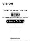
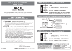
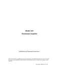
1440B
FAC TORY KEYL ESS UPGRADE SECURIT Y
© 2005-2014 KIRAMEK, INC., Aichi Japan
Ver. 2.1, Feb. 2014
Thank you for purchasing this VISION
1440B Vehicle Security System. The 1440
is a state of the art device that will provide you with years of trouble free service if used properly. Please familiarize
yourself with the content of this Owner’s
Guide to get the most out of your new
system. We trust you will enjoy using the
product.
TABL E OF CONTENTS
Limited Lifetime Warranty ................................... 1
Included Items ............................................ 2
System Operation ......................................... 3
Arming ................................................ 3
Disarming ............................................. 3
Trunk Release .......................................... 4
System Features ........................................... 5
Door Trigger ........................................... 5
Ignition Trigger ......................................... 5
IIP (Intelligent Ignition Protect) ........................... 5
Status LED ............................................. 6
SBS (Sector Bypass System) ............................... 6
GWA (Ground When Armed) ............................. 7
2-Stage Sensor Trigger ................................... 7
Light Flash ............................................. 7
Feature Programming ...................................... 8
Program Features Explained ................................ 9
Force Reset ............................................. 11
Troubleshooting .......................................... 13
Compatibility & Options ................................... 15
NOTICE! Although reasonable efforts have been taken to ensure accuracy in this
Owner’s Guide, Kiramek Inc. shall not be held liable for any errors, omissions, property damage, or injury resulting from the use of this information.
All product specifications and features are subject to change without notice.
© 2005-2014 KIRAMEK, INC.
L imited L ifetime Warrant y
The VISION 1440 system control unit is backed by a limited lifetime
warranty against defective components and/or improper product assembly to the original purchaser for as long the vehicle is owned by that
same purchaser, contingent upon installation by an Authorized VISION
Dealer. All product warranties become void if the VISION 1440 system
was not sold and installed by an Authorized VISION Dealer or the system is moved to another vehicle. All other parts and/or accessories that
connect to VISION 1440 systems, including the shock sensor and status
LED, are warranted for one (1) year from the original date of purchase.
During the warranty period, Kiramek Inc. will repair or replace, at its
sole discretion, any system component that is found defective in material or assembly during the warranty period, provided that the product
is returned to Kiramek Inc. by an Authorized VISION Dealer and is accompanied by a clear and legible copy of the original purchaser’s receipt.
Any damage to your VISION 1440 system that results from normal
wear-and-tear, accidents, improper use, neglect, faulty wiring, incorrect
number, alteration or repair outside Kiramek Inc or its Authorized VISION Dealers immediately voids this warranty.
This warranty is limited to defective parts only and does not provide
any compensation whatsoever for damages associated with the VISION
1440 system or its accessories. This warranty does not cover installation labor, product removal and/or reinstallation fees. This warranty
is valid for the original purchaser only and may not be transferred to
another party. Kiramek Inc makes no warranty against theft or vandalism of the vehicle in which the VISION 1440 system was installed. This
warranty shall not be interpreted as an insurance policy against loss,
otherwise.
WARNING! DO NOT ATTEMPT TO INSTALL THIS VISION 1440 PRODUCT YOURSELF BECAUSE SUCH WILL IMMEDIATELY VOID THE WARRANTY. THIS SECURITY SYSTEM MUST BE PROFESSIONALLY INSTALLED BY YOUR AUTHORIZED
VISION DEALER TO VALIDATE YOUR WARRANTY.
1
© 2005-2014 KIRAMEK, INC.
INC L UDED ITEMS
Control Module (1pc)
Mounting Bracket (1pc)
Primary Harness (1pc)
IR
VI
SH
SI
OC
K
ON
SE
NS
OR
Secondary Harness (1pc)
Status LED (1pc)
Shock Sensor (1pc)
Sensor Harness (1pc)
2-Sided Tape (1pc)
Backup Siren (1pc)
2 keys included
0
14 4
Window Decals (2pc)
VISION 1440B OWNER’S GUIDE
B
1440B
Guides (2pc)
2
System Operation
ARMING
NORMAL ARMING
This method is the typical way to arm the 1440,
with the shock sensor enabled. Ensure that all doors
are closed and then press the LOCK button on the vehicle’s factory keyless remote. After you press Lock, vehicle
hazard lights stop, the siren will chirp 1 time and Status
LED will light solid for 5 seconds. After 5 seconds, the
tive. (No triggers are active during the initial 5 seconds.)
0USHå,/#+
"UTTON
LOCK
UNLOCK
TRUNK
(FACTORY REMOTE)
SENSOR BYPASS ARMING
This arming method allows you to disable the shock sensor
while keeping other alarm triggers active (e.g., door, trunk,
ignition). Run the engine for more than 10 sec., then turn the
ignition ON & OFF 3 times within 10 sec. You now have 10 sec. to
exit the vehicle, close all doors, and press the LOCK button on the vehicle’s
is now armed, and all triggers except shock are active.
LOCK-UNLOCK-LOCK: This is an alternate Sensor Bypass Arming
method. It’s especially convenient on Push Start cars, where turning the
ignition ON/OFF multiple times is troublesome. After running the engine
for more than 10s, turn off the ignition and within 10 seconds exit the vehicle
and Lock via keyless remote; then within 5s, Unlock; then within 5s, Lock
again. The 1440 will then be Armed with the shock sensor Bypassed.
DISARMING
Press the UNLOCK button on the vehicle’s factory
keyless remote. After you press Unlock, vehicle hazhazard lights stop, the siren will chirp 3 times and Status
LED will turn off. The system is now disarmed and you
may enter the vehicle.
3
0USHå5.,/#+
"UTTON
LOCK
UNLOCK
TRUNK
(FACTORY REMOTE)
VISION 1440B OWNER’S GUIDE
Sys tem Operation
DISARMING TIPS
The 1440 determines when to disarm by watching the state of
the door lock motors and the hazard lights in conjunction with a
disarm button press on the vehicle’s keyless remote. If the siren
is going off when you disarm, the siren will continue going off for
Please consider that the following actions could trigger the siren when you
disarm:
• SIREN WILL GO OFF: If door is unlocked with the key instead of the
factory keyless remote.
• SIREN MAY GO OFF: If a door is opened too quickly after disarming
• SIREN MAY GO OFF: If a door is opened too quickly after disarming
while the siren is still chirping.
NOTE: There are some rare cases where the factory keyless signal may
drift and prevent disarming for a single session. In this case, simply lock
and then unlock again to disarm. The 1440 will then compensate for the
drift.
TRUNK RELEASE
Press the TRUNK button on the vehicle’s factory
keyless remote (your factory remote may not have
this feature). The shock sensor, door and trunk triggers will be bypassed and the trunk will then open. (The
Ignition switch trigger remains active, and doors remain
locked.) Five (5) seconds after you close the trunk, the
door, shock sensor, and trunk triggers will be automatically re-activated.
© 2005-2014 KIRAMEK, INC.
4
SYSTEM FEATURES
DOOR TRIGGER
The siren will blast for 30 seconds when the door is opened while the sys(You may disarm
anytime with the vehicle’s factory remote.)
IGNITION TRIGGER
IG PROTECT MODE (default)
The siren will blast for 30 seconds when the ignition switch is turned on
(You
may disarm anytime with the vehicle’s factory remote.)
REMOTE START COMPATIBILITY MODE (user-selectable)
When the ignition goes on while the system is armed, the
siren will not go off. Instead, shock sensor and ignition triggers are bypassed, while door and trunk triggers remain active.
This allows a 3rd party remote start system to turn on the engine
without triggering the 1440’s siren. The 1440 is still protecting the vehicle,
so any attempt to open a door or the trunk will trigger the siren. And when
the remote starter shuts down (i.e., ignition is turned off), the shock sensor
and ignition triggers are automatically re-activated.
IIP (Intelligent Ignition Protect)
When you activate Remote Start Compatibility Mode,
the 1440 uses a feature called “IIP” to automatically
switch back to IG Protect Mode when needed.
ON
ST
ACC
OFF
Background. Most “remote start / turbo timer” compat-
ible car alarms bypass all trigger inputs when the ignition goes on (while
armed). If a thief opens the door the siren will go off, but the thief can then
close the door, turn on the ignition and wait. When the siren stops, he
can drive away in silence because the Ignition-ON state prevents the siren
from going off again! Yet other car alarms trigger the siren when the ignition goes on (while armed), offering no remote start or turbo timer compatibility. IIP solves this “compatibility versus security” problem.
5
© 2005-2014 KIRAMEK, INC.
Sys tem FEATURES
How IIP Works. Normally, if the ignition is turned on while in Remote
Start Compatibility Mode, the system automatically bypasses the sensor/ignition inputs but keeps door/trunk inputs active. However, if the 1440
was triggered before the ignition was turned on (via door/trunk/sensor), IIP
automatically switches back to IG Protect Mode and triggers the siren
when the ignition is turned on. The siren will blast for 30 sec. and repeat
up to 7 times while the ignition remains on.
STATUS LED
acting as a visual theft deterrent. The LED turns off when the system is
disarmed.
TRIGGER MEMORY
to Table-1 below to show which vehicle sector triggered the siren.
This “Trigger Memory” will display on the Status LED until the
system is disarmed.
TABLE-1
Trigger Memory Report via the Status LED
Status LED Flashes
Sector That Triggered Siren
2
Door or Trunk
6
Ignition
7
Sensor
SBS (Sector Bypass System)
When a vehicle sector is triggered repeatedly, the system will automatically bypass that sector until you disarm and arm again.
This feature is useful to prevent noise pollution caused by multiple siren triggers in a short period of time, such as when parking near construction sites or when animals jump on the vehicle.
• Ignition Trigger Limit: 8 triggers
• Sensor Trigger Limit: 8 FULL triggers, 10 WARNING triggers (pg.7)
• Door Trigger Limit: 4 triggers
VISION 1440B OWNER’S GUIDE
6
SYSTEM FEATURES
GWA (Ground When Armed)
The 1440 feeds a (–) Ground output while the system is armed. Optional
components can be added to this control line, such as a Starter Kill Immobilizer Relay or vehicle lighting devices. When the system is disarmed,
power to this output is removed and all attached devices shutdown. See the
Installation Guide
2-STAGE SENSOR TRIGGER
1st Stage (“Warning Chirps”). When the included shock sensor
detects a light impact to the vehicle body, the siren will chirp 5
times. Note that any optional sensors attached to the shock sensor’s 1st Stage input can also trigger 5 warning chirps. No chirps
will be produced while in Sensor Bypass Mode.
2nd Stage (“Full Siren”). When the included shock sensor de-
tects hard impact on the vehicle body, the siren will go off for 30
seconds (or until disarmed with the factory remote). Note that
any optional sensors attached to the shock sensor’s 2nd Stage
input can also trigger the full siren blast sequence. The siren will not be
triggered while in Sensor Bypass Mode.
LIGHT FLASH
nection to the vehicle’s factory light control relay (see “Installation
Guide” page 9). For some vehicles, you may need to change the polarity with the purchase of an optional VISION 896H-1C relay.
(e.g., shock sensor 1st-stage trigger).
PAGER OUTPUT
This wire goes to (–) Ground for 15 seconds whenever the full siren blast is
triggered (not during Warning Chirps). It supplies up to 1-Amp to power
optional paging systems (not currently available from KIRAMEK) or other
devices you wish to turn on only when the siren is going off.
7
© 2005-2014 KIRAMEK, INC.
FEATURE PROGRAMMING
Many system features are user-programmable. To program features you will need to open the 1440 control
module and use the Program Switch inside. (If you cannot access the Control Module, ask your VISION dealer
to set features for you.) Once you have the control module case open, perform the following 3-step procedure to
alter the features shown in Table-2 below:
Program Switch
1. Disarm the system. (Or “Arm-then-Disarm” if repeating this procedure.)
2. Within 5 sec. of disarming, press and release the Program Switch.
3.
Count the
.
wish to change in Table-2, press the Program Switch again. The
LED will change from RED to GREEN. The Green LED shows the feashould match the feature number you have chosen. To go back to the
previous setting, Arm the system and repeat this procedure at Step-1.
NOTES: (1) There is no visual indication to let you know which setting
(2) If you never press the Program Switch a second time in Step-3 above,
and then go back to Step-1 to re-enter feature programming. (3) You
must repeat this procedure for each feature you wish to program.
TABLE-2
Feature Selection Menu
No.
Feature Description
Toggle Settings
6
Confirmation Chirps
ON
OFF
7
Vehicle Lights ON During Remote Start
ON
OFF
8
IG Protect Mode / Remote Start C. Mode
IG Protect
RSCM
9
Siren Output
Continuous
Pulsed
10
IIP Trigger Selection
All
Door
13
Error Chirp
ON
OFF
14
Exit Delay Time Selection
5 sec.
40 sec.
FACTORY DEFAULT SETTINGS SHOWN IN BOLD TEXT ABOVE
VISION 1440B OWNER’S GUIDE
8
PROGRAM FEATURES EXPL AINED
Confirmation Chirps
When set to ON (default), the siren will chirp 1 time when the system is
Armed and 3 times when the system is Disarmed.
When set to OFF , the siren won’t chirp 1/3 times when Armed/Disarmed.
Vehicle Lights ON During Remote Start
When set to ON , vehicle lights will illuminate when the Ignition is turned
on by a remote start system.
installed, and only if Remote Start Compatibility Mode is also turned ON.)
IG Protect Mode / Remote Start Compatibility Mode
When set to IG Protect Mode , the system will trigger the siren when the
Ignition goes on, as described on page 5 of this manual.
When set to Remote Start Compatibility Mode (RSCM) , the system
will bypass the Shock Sensor and Ignition triggers, and IIP will become
active, as described on page 5 of this manual.
Siren Output
When set to Continuous (default), the system will feed a continuous (–)
Ground output to sound the included siren for 30 seconds (full trigger).
When set to Pulsed , the system will feed a pulsed (–) Ground output. This
can be used to create a unique siren sound on the included siren, or to connect to the vehicle’s horn via an optional relay.
IIP Trigger Selection
When Remote Start Compatibility Mode is ON, you may select which “trigger sectors” IIP uses to temporarily switch the system back into IG Protect
Mode while IG is off. You have two programming choices: (1) ALL: switch
to IG Protect Mode upon sensing a door open condition and/or a sensor
trigger; or (2) DOOR: switch to IG Protect Mode upon sensing only a door
open condition.
9
VISION 1440B OWNER’S GUIDE
PROGRAM FEATURES EXPL AINED
Here is how IIP responds when set to “ALL”:
• If a door is opened and/or if a sensor was triggered, the system will automatically switch to IG Protect Mode and trigger the siren, and turning
on IG will continue to trigger the siren up to 7 times (30 sec. each time).
IIP will then automatically switch back to Remote Start Compatibility
Mode when the system is disarmed by the remote.
Here is how IIP responds when set to “DOOR”:
• If a door is opened, the system will automatically switch to IG Protect
Mode and trigger the siren, and turning on IG will continue to trigger
the siren up to 7 times (30 sec. each time). IIP will then automatically
switch back to Remote Start Compatibility Mode when the system is
disarmed by the remote.
• If only a sensor was triggered (no door opened), and later if the ignition
goes on, the siren will not go off and the shock sensor will be bypassed in
accordance with normal “Remote Start Compatibility Mode” functionality.
Error Chirp
When set to ON (default), the siren will chirp 1 time* when you Arm and
then chirp 5 more times if there are any unsecured trigger sectors (like a
door ajar, trunk open, etc.).
When set to OFF , the siren will chirp only 1 time* when you Arm, even if
there are unsecured sectors.
on Chirps” is set to ON. Also, turning off “Connot turn off Error Chirps.
Exit Delay Time Selection
After Arming, there is a default 5 sec. delay before the system will accept
to let the vehicle settle after you exit and close the door so the shock sensor
will not be triggered by residual vibration. You can change this delay to
40 sec. for compatibility with vehicles (e.g., Subaru) that place a long 30
second lock pulse on the door lock lines when the keyless remote is used.
© 2005-2014 KIRAMEK, INC.
10
FORCE RESE T
Purpose
In the event the battery in your factory remote dies or the factory remote
itself is lost, the 1440 can be manually reset (i.e., “disarmed”) using a secure procedure.
Programming Your Unique Reset Code
The VISION factory default Reset Code is set to
“6.” It is strongly recommended that you change this
code to something unique. To change the Reset Code
you will need to gain access to the Control Module and
open the case to use the Program Switch. If you cannot do this yourself, please ask your VISION dealer/installer to assist you.
Program Switch
The following procedure will allow you to change the Reset Code:
1. Arm and then immediately Disarm with the factory remote.
2. Within 5 seconds of Disarming, press and release the Program Switch.
(The LED inside the Control Module will start to turn on and off very
3. Turn on the Ignition before
(Continue counting
4. When the LED lights up for the 5th time, press and hold the Program
Switch and then release the button when the LED turns Green. The
Consider the Reset Code number you want to program before the LED
5.
off the Ignition. The LED will turn Green again and the siren will chirp
NOTE: Make time now to record your new Reset Code and store it
in a safe place.
11
© 2005-2014 KIRAMEK, INC.
FORCE RESE T
Using Your Reset Code to Disarm
1. Open the driver’s side door. The siren will now go off.
2. With the door still open, turn the Ignition ON and
OFF the same number of times as the Reset Code
you programmed. (If no unique Reset Code has been
programmed, then turn the Ignition ON and OFF 6
times.)
ON
ST
ACC
OFF
3. Close the driver’s side door and the 1440 will disarm.
NOTES:
• The siren will go off when you open the door in Step-1 above. If you en-
ter an incorrect code and then close the door, the siren will continue to
sound for the full 30 seconds. (If your code was correct, the siren should
stop immediately when you close the door.)
• If you fail to close the door per Step-3 above but the disarm code you
entered was correct, the siren will stop after 30 seconds and the system
will disarm at that time. Step-3 above simply quiets the siren immediately after you have entered a correct code.
• If you did not enter a correct code and you closed the door, the siren will
keep going off for the full 30 seconds and then stop. To try entering
your code again, you need to repeat the procedure above, which involves
opening the door and triggering the siren again. (If you choose to leave
the door open continually, the siren will go off for 30s, then stop for 8s,
then go off again several times until you either close the door or enter
a correct code. You can attempt to enter your code once every 30s siren
blast.)
VISION 1440B OWNER’S GUIDE
12
TROUBL ESHOOTING
FACTORY KEYLESS REMOTE WAS LOST!
If the factory remote was lost or the battery dies, you can still disarm
the 1440 by using your Force Reset Code, as detailed on pages 11-12.
CAN’T MAKE SIREN GO OFF AFTER ARMING
• You may have Armed using the Sensor Bypass Method. See page 3.
•
you Armed the system? If not, the Ignition may be on. You cannot
Arm the system when the Ignition is ON while “IG Protect Mode” is
active. See page 9 for details on IG Protect Mode.
THE SYSTEM ARMS SOMETIMES AND NOT OTHERS
Some vehicles exhibit more door lock “signal drift” than others. The
drift causes the 1440 to misread the signal. This occasional drift may
prevent arming for a single session. In such cases, simply unlock and
then lock again to arm. The 1440 will then compensate for the drift. We
do not make the 1440 door lock signal detector read signals more loosely
for reasons of security.
THE SYSTEM DISARMS SOMETIMES AND NOT OTHERS
Some vehicles exhibit more door lock “signal drift” than others. The
drift causes the 1440 to misread the signal. This occasional drift may
prevent arming for a single session. In such cases, simply lock and then
unlock again to disarm. The 1440 will then compensate for the drift.
We do not make the 1440 door lock signal detector read signals more
loosely for reasons of security.
SIREN GOING OFF WHEN TRUNK IS OPENED
• You cannot open the trunk with the key or the siren will sound. Use
the keyless remote. If your keyless remote doesn’t have a trunk open
your factory remote) and then open the trunk.
• Conversely, if the siren isn’t triggered when the trunk is manually
opened with a key (while Armed), then it’s likely the trunk trigger
input was not connected. Consult with your installer.
CANNOT DISARM WHILE THE SIREN IS SOUNDING
• Make sure all doors and the trunk are closed and then try to disarm.
• Try to Arm and then Disarm.
13
VISION 1440B OWNER’S GUIDE
TROUBL ESHOOTING
AFTER DISARMING, SIREN STILL GOES OFF WHEN DOOR OPENED
The 1440 reads the door locking signals in combination with the hazard
lights (turn signal lights) to know when to Arm and Disarm. You must
too quickly after disarming is the main cause of the siren going off.
CANNOT ARM WHILE 3rd PARTY TURBO TIMER IS IN USE
• Check if the doors lock/unlock via the factory remote while the turbo
timer is running. If not, the vehicle’s factory keyless system is incompatible with your turbo timer, which is why you cannot arm with the
1440.
• If the doors lock/unlock with the factory remote, then make sure you
have programmed “Remote Start Compatibility Mode.” If you are
using “IG Protect Mode” you will not be able to Arm while the Turbo
Timer is running because the Ignition will be switched ON. See page 9
for details.
SIREN GOES OFF AFTER I FINISH DRIVING AND THEN OPEN A DOOR
This problem occurs when IIP is enabled (see page 8) and the 1440’s
GRN wire is not properly connected to IG as shown on page 12 of the
Installation Guide. Keep in mind that if you connect the GRN wire to
positive +12v Ignition, your trunk release connection (if any) must also
be the same (+) polarity. (Default DIP switch polarity is set to (+).)
SHOCK SENSOR 1st STAGE TRIGGER (“WARNING”) DOESN’T WORK
Examine the shock sensor (318-052) and look closely at the two LEDs.
When you lightly tap on the sensor, do you ever see a Green LED light?
• If you never see Green light, adjust the sensitivity knob on the sensor.
• If you see Green light the sensor is properly sending out the 1st Stage
Trigger signal. Check that the sensor wire harness is properly connected at both ends.
FULL SIREN BLASTS WITH ONLY LIGHT IMPACT TO THE VEHICLE
• Turn down the shock sensor sensitivity.
• If you also have an optional Ultrasonic sensor installed in addition to
the included shock sensor, it is very likely that the main body of the
Ultrasonic sensor (not the emitters) was placed too close to the shock
sensor body. The Ultrasonic sensor body should be moved more than
30cm (1 foot) away from the shock sensor to avoid interference.
© 2005-2014 KIRAMEK, INC.
14
COMPATIBIL IT Y & OP TIONS
Why are “aftermarket” keyless systems incompatible with the 1440?
“Factory Keyless Entry” is a compatibility requirement for the 1440.
The reason is because most aftermarket keyless entry systems are atwhenever the motor activates. The problem with this is that if a thief
unlocks a door with the metal car key (or screw driver), the door lock
What makes “factory” keyless systems compatible?
• Most
insert the metal car key in the door and then turn to lock/unlock.
• It’s always important to test your vehicle to verify if your factory key-
less system is truly compatible with the 1440. Indeed, KIRAMEK has
not compatible even though they
have factory keyless! Test your vehicle by inserting the metal car key
in the driver’s door and turn it to Lock and then again to Unlock. Do
Do I need optional devices in order to install the 1440?
For some cars, yes. The two most common VISION part numbers are:
• PBS-30: Push Start compatibility switch (substitutes for Ignition)
• DSS-6: door/trunk pin switch connection interface with built-in isolation diodes — used for Smart Key or Intelligent Key compatibility.
Why aren’t the PBS-30 and DSS-6 parts standard?
Because in the past, most cars did not have Push Start or Smart Key
or Intelligent Key features. As these vehicles become more prevalent,
we may at some point in the future include these parts as standard
features.
What other options should I consider for the 1440?
• 896H-1B Starter Kill Relay.
• DSS-6 Diode-isolated 6-way wire splitter (for Door/Trunk/Hood).
• Optional sensors like: MMF-2 (radar), 318-054 (shock with dual adjustments), 318-022 (tilt), 318-04 (ultrasonic), 318-085 (loop)
• 318-035 Sensor Splitter for easy connecting of up to 3 sensors (keep in
mind that the 318-052 shock sensor is standard with the 1440).
• 896H-1C relay: to invert polarity or drive high current devices.
• Luminator LED Scanners
• Other optional parts can be found at: www.visionsecurity.jp/en/
15
© 2005-2014 KIRAMEK, INC.
NOTES
VISION products are engineered in Japan and manufactured in
strict accordance with Japanese QC standards at an ISO9000/
QS9000 certified factory.
9-183-1 Itayama-cho, Handa-shi, Aichi-Ken 475-0936 JAPAN
TEL: +81-569-20-5585 • FAX: +81-569-20-5586 • EMAIL: [email protected]
1440B
FAC TORY KEYL ESS UPGRADE SECURIT Y
© 2005-2012 KIRAMEK, INC., Aichi Japan
Ver. 1.8, Mar.’12
INSTALLERS, READ THIS MANUAL THOROUGHLY!
The 1440B must be connected by an experienced VISION installer. All product warranties immediately become void if the 1440 is not
installed by an authorized dealer.
If you acquired this product without professional installation, DO NOT install it yourself
to save a little money at the risk of damaging
your vehicle or causing physical injury.
TABL E OF CONTENTS
Precautions & Safety ....................................... 1
Installation Tips ........................................... 2
Technical Specifications ................................... 3
Included Items ............................................ 4
Control Module Overview .................................. 5
System Wiring Diagram ..................................... 6
Door Lock & Hazard Light Wiring ............................. 7
The 8-pin Main Harness (H1) ................................ 8
The 4-pin Interface Harness (H2) ............................ 11
The Shock Sensor Harness (H3) ............................. 13
Mounting System Components ............................. 14
Adjusting the Shock Sensor ................................ 16
Learning the Keyless Signals ............................... 17
Feature Programming ..................................... 18
Troubleshooting .......................................... 19
Factory Reset ............................................ 20
NOTICE! Although reasonable efforts have been taken to ensure accuracy in this
Installation Guide, Kiramek Inc. shall not be held liable for any errors, omissions,
property damage, or injury resulting from the use of this information.
All product specifications and features are subject to change without notice.
© 2005-2012 KIRAMEK, INC.
Prec autions & Safety
OPERATION . Use of the 1440B outside its intended purpose as described
in this Installation Guide and the 1440B Owner’s Guide, could result in
damage to the vehicle or surrounding property, or cause serious injury or
even death. As the installer of this security system, it is your responsibility to ensure that the vehicle owner is properly informed of all the details of
your installation which are pertinent to safety.
SAFETY POINTS TO ABIDE BY :
1. Never start the vehicle’s engine in enclosed spaces that lack adequate
ventilation. Extended exposure to carbon monoxide exhaust fumes
can result in death!
2. Do not disconnect the vehicle’s battery, as it could cause serious prob-
lems with airbag systems, anti-theft radios or vehicle diagnostics. If
the main power wiring harness of the 1440 and then disconnect the
vehicle’s battery.
3. Do not proceed with installing this system in vehicles that do not have
a 12-volt electrical system. This system will not function in 24-volt
trucks, and any damage resulting from such installation shall be the
sole responsibility of the installer.
4. Do not install the 1440 control module or associated sensors in or
near water, or in a location where water could gather. The 1440 is
not waterproof and an electrical short could occur if water gets inside. Only the siren can safely be installed in the engine compartment.
5. Do not install the 1440 control module in an environment of intense
condensing humidity or steam, in an area with an unusally large
number of airborne particles, or any place where oil could build up
inside the control module case. All of these extreme environments
6. Avoid installing the 1440B and its associated sensors near sources of
intense RF transmissions which could possible interfere with the opnot working, consider relocating the control module and/or sensors.
1
© 2005-2012 KIRAMEK, INC.
Insta l l ation Tips
Steps Toward a Professional Installation:
•
Secure all electrical contacts so you cannot easily break the connection
by tugging on the wires. Use solder if required, and securely cover all
connections with splice clips, electrical tape, heat shrink tubing and/or
corrugated tubing.
•
Use only a DMM (digital multi-meter) to test leads or take voltage readings. Do not use “test lights” or “logic probes” (“computer-safe test
lights” included) because they draw a large amount of electrical current
that could overload and destroy sensitive circuitry in the vehicle.
•
Manually turn off all lights (such as the dome light) that trigger when
a hatch is opened so you will not run down the battery. If you cannot
manually turn off all the lights, then remove the appropriate fuses and
don’t forget to replace the fuses after your installation is complete.
•
Remember to not lock the keys in the car during your installation!
Leave a door open or roll down a window, just in case.
•
Consult the vehicle owner about where the Status LED, Control Module,
Siren and Sensors should be mounted.
•
•
dash, run a thick-gauge wire direct to the battery terminal. Do not disconnect the battery, but rather connect to the battery terminal clamps
by removing the appropriate bolts.
use a wire gauge that is at least as big or bigger than the wire you are
extending.
Recommended Tools and Accessories:
•
DMM (digital multi-meter)
•
Soldering Iron & Solder
•
Battery-powered drill & driver
•
Corrugate Tubing
•
Electrical Tape or Heat Shrink Tubing
•
Wire Stripper/Crimper
VISION 1440B INSTALLATION GUIDE
2
Technic al Specific ations
Control Module
Operating Voltage:
(Conforms to IP40 standard)
12Vdc
Current Consumption: 5mA (armed w/ LED flashing, excludes shock sensor)
Operating Temp.:
-40°C to +85°C
Onboard Fuse:
5A rated, mini blade type
IP40, but also passed IP50 tests)
Shock Sensor
Operating Voltage:
12Vdc (fed from Control Module)
Current Consumption: 5.0mA (avg.)
Operating Temp.:
-40°C to +85°C
Sensor Technology:
Infra-red Beam Deflection
Trigger:
2-Stage
Status LED
Mount:
2-sided tape (no drilling required)
LED Light Color:
Red
Life:
100,000 hours (greater than 11 years)
Siren
Operating Voltage:
(Conforms to IP54 standard)
12Vdc
Current Consumption: 5mA trickle charge, 1A max. (during full siren blast)
Operating Temp.:
-40°C to +125°C
Loudness:
125dB (measured 30cm/1ft from speaker)
Audio Generator:
1-tone (6-tone selectable by cutting wire on siren)
Housing:
Water-resistant (cannot be submerged)
3
VISION 1440B INSTALLATION GUIDE
INC L UDED ITEMS
Control Module (1pc)
Mounting Bracket (1pc)
Primary Harness (1pc)
IR
VI
SH
SI
OC
K
ON
SE
NS
OR
Secondary Harness (1pc)
Status LED (1pc)
Shock Sensor (1pc)
Sensor Harness (1pc)
2-Sided Tape (1pc)
Backup Siren (1pc)
2 keys included
0
14 4
Window Decals (2pc)
© 2005-2012 KIRAMEK, INC.
B
1440B
Guides (2pc)
4
CONTROL MODUL E OVERVIEW
1440 Control Module
5A Fuse
ON
2-Color LED
(Red/Green)
IC
Program Switch
DIP SWITCH (to set input signal polarity)
Negative Polarity (–)
ON
OFF
4
Hazard Light Polarity
3
Door Unlock Polarity
2
Door Lock Polarity
1
ON
DIP SWITCH SETTINGS
(All OFF by Default)
Trunk Release Polarity
(+) Positive Polarity
CAUTION! For most vehicles, it is strongly advised that you do not
change DIP switches 2 & 3 (Lock/Unlock Polarity). The default setting
the polarity to (–) Negative is if you can gain access to wires between
a factory keyless module and the factory door lock relay module. See
“Door Lock & Hazard Light Wiring” on page 7 for details.
5
© 2005-2012 KIRAMEK, INC.
SYSTEM WIRING DIAGRAM
H1
Status
LED
H2
Shock
Sensor
H3
WHT/RED
Hazard Light Input
BLU/YEL
Door Unlock Input
GRN
GRN/YEL
YEL
Trunk Release Input
Door Lock Input
(-) GWA / ST Kill Output
YEL/RED
(-) Pager Output
GRN/WHT
(+) Ignition Input
ORG
(-) Siren Output
GRN
(-) Light Flash Output
BLK
(-) System GROUND
WHT
(-) Door / Trunk Input
RED
(+) 12v System POWER
VISION 1440B INSTALLATION GUIDE
6
DOOR LOCK & HAZARD L IGHT WIRING
$OORå,OCKå37
Never connect to the LOCK/UNLOCK wires between Door Lock Switch & Relay Module!
For most vehicles, connect to the wires at the motor. You normally do not need
to change the default Control Module DIP SW settings (“+” is default).
Door Lock
Relay Control
Module
LOCK
$RIVERSå$OORå,OCKå-OTOR
LOCK
UNLOCK
0ASSENGERSå$OORå,OCKå-OTOR
UNLOCK
FACTORY KEYLESS
MODULE
2EARå$OORå,OCKå-OTOR
NOTE: Leave the 1440 WHT/RED
“Hazard Input” wire disconnected if
connecting to the LOCK/UNLOCK
wires between the Factory Keyless
Module and the Door Lock Relay
Control Module. A change to DIP
switches 2 & 3 may be required.
(Not possible with most vehicles.)
BLU/YEL (UNLOCK)
2EARå$OORå,OCKå-OTOR
NOTE: For installation in most
vehicles, you should not alter 1440
DIP switches 1, 2 or 3. They are
factory set to OFF (“+”).
GRN/YEL (LOCK)
,%&4
4URNå3IGNAL
,IGHTS
TIP: It doesn’t matter if
you connect to the LEFT
or RIGHT sides.
LEFT
2)'(4
4URNå3IGNAL
,IGHTS
RIGHT
Vehicle Light Flash
Relay Module
H2
Har ness
NOTE: “Turn Signal”
lights are defined as
“Hazard” lights in this
manual.
WHT/RED
7
© 2005-2012 KIRAMEK, INC.
H1 THE 8-PIN MAIN HARNESS
H1-1 YEL wire: (–) GWA / Starter Kill Output
This wire supplies (–) 0v ground (500mA max.) while the 1440 is armed.
This output is intended to be connected to the Yellow wire (“86”) of the optional 896H-1B starter kill relay harness, as shown in Fig-1 below.
H1
("
2%,!9
FIG-1: Starter Kill Wiring
STARTER
TIP: You may also attach low-current devices, such as scanning LEDs, to
the YELLOW wire. These devices will turn on when the 1440 is armed. A
relay will be needed if your combined devices (including starter kill relay)
exceed 500mA.
H1-2 YEL/RED wire: (–) Pager Output
H1
9%,2%$
H1-3
This wire supplies (–) 0v ground (1.0A max.) for 15 seconds while the siren goes off, for triggering optional paging systems. This wire can also be used to activate automotive illumination products, such as strobe lights, to
enhance the “intrusion alert” status of the 1440. Add a
relay if your combined attachments will exceed 1.0A.
GRN/WHT wire: (+) Ignition Input
/.
34
Ignition line (showing 12v when IG switch
is turned on). The connection of this wire
is vital for triggering the siren when the
/&&
'2.7(4
ignition goes on (while armed) or for re)'.)4)/.
37)4#( mote start compatibility, and for Force
Reset (manual disarm). See PBS-30 (optional part) instructions if you have a Push Start ignition switch.
H1
!##
VISION 1440B INSTALLATION GUIDE
8
H1 THE 8-PIN MAIN HARNESS
H1-4 ORG wire: (–) Siren Output
This wire supplies a (–) 0v Ground (1.5A max.) output to operate the included battery backup siren during a security breach. See Fig-2 below.
BRN
BLUE
LOOP
H1
MAIN
HARNESS
ORG
connect
FIG-2: Siren Connections
ORG
Cut Blue Loop for 6-tone sound.
TIP: If the 1440 is programmed to “pulsed” siren output (see “Owner’s
Guide” page 8), you can connect to the vehicle’s horn by adding an optional
relay to the ORANGE wire. (You can also use the “pulsed” output setting
when connecting to the included siren, if you wish.)
H1-5 GRN wire: (–) Light Flash Output
hicle’s Parking lights (or “Small lights”) during security breaches (at times
of Warning Chirps and Full Siren Blast). See Fig-3 below.
V
6%()#,%
,)'(4
H1
'2.
FIG-3: Connecting Light Flash
6%()#,%
,)'(4å37)4#(
6%()#,%
,)'(4å#/.42/,å2%,!9
NOTE#1: NEVER use the GRN wire to control the Hazard lights — the 1440
will not function properly! Interface with Parking or Small lights only.
NOTE#2: The relay shown in Fig-3 is not an “optional” relay. Fig-3 shows
the vehicle’s factory relay attached to the factory light switch. The 1440’s
GRN wire only has enough power to drive the factory relay only. Never
connect the GRN wire directly to the vehicle lights! If you need to invert
the polarity to (+)12v and directly power the lights, you will need to
purchase an optional VISION 896H-1C relay.
9
VISION 1440B INSTALLATION GUIDE
THE 8-PIN MAIN HARNESS H1
H1-6 BLK wire: (–) System Ground
H1
6%()#,%
'2/5.$
",+
This wire is the main (–) ground input to the 1440
system. Be sure to connect this wire securely to a
good ground source. Most security system installation problems result from a bad ground connection!
H1-7 WHT wire: (–) Door/Trunk Input
This input wire detects if a door or the trunk is opened—if opened while the
1440 is armed, the siren will go off. The connection is made between the door
and/or trunk switch and the dome and/or trunk light, as shown below in Fig4. The switches shown are open-ciruit (no ground) when the door/trunk is
closed. If using the optional DSS-6, refer to that manual instead of Fig-4.
H1
FIG-4: Connecting Door/Trunk
NOTE: If you connect the WHITE wire to the trunk, you must also be sure
to connect the GREEN wire of the H2 Harness (see page 12). Otherwise,
the siren will go off when the trunk is opened while the 1440 is armed.
H1-8 RED wire: (+) 12v System Power
H1
2%$
to the 1440 system. Be sure to connect this
wire securely to a constant 12v source. Connect this wire last to ensure the siren doesn’t
"!44%29 go off. If you need to extend this 12v power
wire, use wire thicker than the RED wire.
© 2005-2012 KIRAMEK, INC.
10
H2 THE 4 -PIN INTERFACE HARNESS
H2-1
WHT/RED wire: Hazard Light Input
This input connects to the vehicle’s Hazard (turn signal) lights and works in
combination with the door lock and unlock inputs to inform the 1440 when
to arm/disarm. See Fig-5 below.
H2
FIG-5: Connecting the Hazard Light Input
Connect the WHITE/RED wire as shown in Fig-5, between the vehicle’s
Light Flash Unit and the turn signal light. The correct wire should show
(see page 5).
TIP: In some rare cases, you may not need to connect this WHITE/RED wire
at all if your vehicle has a separate “factory keyless module” that connects to
the “door lock relay control module” (see page 7). In such a case, you would
connect the BLU/YEL (Unlock Input) and GRN/YEL (Lock Input) wires in
between the “factory keyless module” and the “door lock relay control module” instead of connecting between the door lock actuator motors and the
“door lock relay control module” (as shown on page 7).
H2-2 BLU/YEL wire: Door Unlock Input
H2
",59%,
This input normally connects to the unlock wire between
the “door lock relay control module” and the vehicle’s
door lock actuator motors (see page 7). This input is vital
for the 1440 to know when to arm/disarm.
NEVER MAKE YOUR CONNECTION BETWEEN THE DOOR LOCK
“SWITCH” AND THE “DOOR LOCK RELAY CONTROL MODULE”! ONLY
CONNECT TO THE ACTUATOR MOTORS.
11
© 2005-2012 KIRAMEK, INC.
THE 4 -PIN INTERFACE HARNESS H2
H2-3
GRN wire: Trunk Release Input
Don’t Trigger / Don’t Arm Input
This input prevents Arming in RSCM mode and trunk-open siren triggers.
When connecting H1-WHT to the trunk, you must also connect this GREEN
wire (see Fig-6). Trunk-open conditions will then be detected and all alarm
sensors, the trunk, and doors will be bypassed until the last door or trunk
is closed. For use with 3rd party remote starters or turbo timers, note the
optional connection shown in Fig-6 below. NOTE: Trunk Release is not supported when Armed and the remote starter/turbo timer is in use (IG=ON).
H2
+12v Control Line
TRUNK
RELEASE
ACTUATOR
GRN
Add 2 diodes
optional
connection
Connect to “+IGN” for Remote Start compatibility
or
Connect to “+Key-in” for Turbo Timer compatibility
FIG-6: Connections for Trunk Release, Remote Start & Turbo Timer Compatibility
to “–” negative polarity via DIP switch. See page 5 for details.
NOTE: You only need to add the two diodes shown in Fig-6 for the secondary remote start / turbo timer connection. Also, be sure to connect the
GREEN wire only to the IGN wire or the Key-in wire, not both! Lastly, only
connect to a (+)12v Key-in wire, unless you can reverse the polarity.
H2-4
GRN/YEL wire: Door Lock Input
H2
'2.9%,
This input normally connects to the lock wire between
the “door lock relay control module” and the vehicle’s
door lock actuator motors (see page 7). This input is
vital for the 1440 to know when to arm/disarm.
NEVER MAKE YOUR CONNECTION BETWEEN THE DOOR LOCK
“SWITCH” AND THE “DOOR LOCK RELAY CONTROL MODULE”! ONLY
CONNECT TO THE ACTUATOR MOTORS.
VISION 1440B INSTALLATION GUIDE
12
H3 THE SHOCK SENSOR HARNESS
NOTE: If you will not be installing any optional sensors, you can ignore
the shock sensor harness description below. The information given on the
individual shock sensor harness wires is for splicing off to other sensors.
TIP: You can add additional VISION sensors to the 1440 without splicing
wires using the optional VISION 318-035 Sensor Splitter Box.
H3-1 RED wire: (+) 12v Power
Positive power is fed from the 1440 control module through the RED wire
to the shock sensor. You do not need to connect this to any other power
H3-2 BLK wire: (–) Sensor Ground
Negative power is fed from the 1440 control module through the BLACK
wire to the shock sensor. You do not need to connect this to any other
sors.
H3-3 WHT/RED wire: (–) Full Trigger Input
When the shock sensor detects hard impacts to the vehicle, it sends a (–)
ground pulse on the WHITE/RED wire. When the 1440 control module sees
the WHITE/RED wire is grounded, it triggers the full siren blast. When
connecting option sensors, keep in mind that the WHITE/RED wire needs
to see a ground (–) signal for a minimum of 30msec. THE 1440 IS NOT
COMPATIBLE WITH “MULTIPLEX” SENSORS.
H3-4 ORG wire: (–) Warning Input
When the shock sensor detects light impacts to the vehicle, it sends a (–)
ground pulse on the ORANGE wire. When the 1440 control module sees the
ORANGE wire is grounded, it triggers a short series of siren chirps. When
connecting option sensors, keep in mind that the ORANGE wire needs to see
a ground (–) signal for a minimum of 30msec. THE 1440 IS NOT COMPATIBLE WITH “MULTIPLEX” SENSORS.
13
VISION 1440B INSTALLATION GUIDE
MOUNTING SYSTEM COMPONENTS
Control Module
The Control Module is “the brain” of the system and therefore must be
installed in a secure location under the dash. NEVER install the Control
Module in the engine compartment or near any source of heat or moisture!
NEVER place the Control Module near moving parts or in a location where
it can vibrate or move around excessively.
IMPORTANT: When considering an appropriate mounting location, keep in mind that most thieves hot-wire vehicles by removing
the plastic panel just under the steering column.
Locations above or behind the glove box, behind the radio or high up under
the dash (such as above the fuse box) are all good mounting places. However, you may need to extend wires if your chosen location is too far from the
steering column. If you extend wires, always use the same or larger gauge
wire! Solder all large gauge wire connections and cover with electrical tape
or heat shrink tubing and/or corrugate tube. Mount the control module to
Status LED
The Status LED is used as a visual theft deterrent when the system is
armed. It also is used to alert the user if the siren went off in their absence.
Ask the vehicle owner where the Status LED should be placed. If they
have no particular preference, suggest a location near the door window on
the driver’s side where it can be easily seen (e.g., on a switch blank). Use
Siren
from heat sources or moving parts such as belts or the radiator fan. Locate
appropriately sized bolt). If you cannot locate an existing bolt or hole, you
will need to drill holes and use self-tapping screws. Mount in a place that
will not be splashed excessively with water!
© 2005-2012 KIRAMEK, INC.
14
MOUNTING SYSTEM COMPONENTS
Shock Sensor
IR
VIS
SH
OC
K
IO
SE
N
NS
OR
The shock sensor is not waterproof so only mount it inside the cabin. Use
the included double-sided tape and mount the sensor to the inside or outside of the plastic cover that surrounds the steering column. (If mounting
to the outside, just be sure to mount it so the driver won’t constantly bump
it with his or her knees, thereby weakening the 2-sided tape over time.)
You can also mount the sensor on or inside the center console box if vehicle
is so equipped.
It doesn’t matter of the shock sensor is in open view because the sensor
will always sound the siren before someone can break into the vehicle (i.e.,
there is no threat of someone breaking into the car to disconnect the shock
sensor). Indeed, it often makes it much easier to adjust the sensitivity of
the shock sensor by mounting it in a location that is always in view or otherwise easily accessible without removing of many vehicle panels.
You can also mount to the outside of an air duct, to the inside of a trim
panel. But ALWAYS mount to plastic, not to metal! Mounting the sensor
to the metal body of the car will cause sensitivity to become poor.
NEVER use screws or wire ties to mount the sensor! Only mount with the
included 2-sided tape. Make an effort to test the sensor in your preferred
mounting location prior to permanently attaching it with the 2-sided tape.
TIP Always spray brake/parts cleaner on a cloth and wipe the shock
sensor mounting area. We recommend the side of the center console plastics, in open view. Such acts as a theft deterrent and allows easy sensitivity adjustment. “Firm” areas of the center console (places that don’t bend
too much when pressed) yield the best sensitivity. Ensure the seat will
never hit the sensor, and mount it so it will not be easily kicked.
IMPORTANT! Always try to mount the 318-052 shock sensor and sensor wires more than 30cm (1ft.) away from high power antennas in the
car. You must also mount the 318-052 shock sensor more than 30cm (1ft.)
away from the control module of the optional 318-04 Ultrasonic Sensor (if
installed). Failure to do so may cause the shock sensor to randomly false
trigger the siren.
15
© 2005-2012 KIRAMEK, INC.
ADJUSTING THE SHOCK SENSOR
Full Trigger
RED LED
Sensitivity
IR
The shock sensor is factory preset to work well with
most vehicles out-of-the-box (50% setting). Howevif the siren doesn’t go off when you think it should,
it’s time to adjust the sensitivity.
VI
SH
SI
OC
K
ON
SE
NS
OR
SE
N
AD SITIV
JU IT
ST Y
Sensitivity
Adjustment
Warning Trigger
GREEN LED
Turn the sensitivity adjustment knob clockwise to increase sensitivity and
counter-clockwise to decrease
level, consider remounting the shock sensor.
False Alarms
The VISION 318-052 Active-IR shock sensor has been engineered to avoid
false triggers in most situations. However, there is still the possibility
the sensor could trigger the siren during a strong earthquake, jackhammer operation adjacent to the vehicle, hurricane/typhoon, large explosions/
extreme cases are anticipated, you can avoid false siren triggers simply
by Arming the system with the Sensor Bypass Arming, which ignores the
shock sensor (see page 3 of the Owner’s Guide).
Another consideration is temperature. The sensitivity can vary by as much
as 20% under extreme temperature conditions. You may wish to reduce the
sensitivity in very hot weather and increase sensitivity in very cold weather.
Suspended Reflector Malfunction
If the shock sensor is not working well or at all, it may be that the suspended element inside the case was jolted out of position. Disconnect the
wire harness, snap open the shock sensor case, and adjust as shown below.
Incorrect Alignment
C9
R18
C10
D7
C6
REV1
504
318 052
R3
R2
R4
C12
R13
C3
Q2
C12
REV1
C10
318 052
D7
C6
C5
R8
R19
C9
C4
R18
R13
C3
Q2
C12
REV1
318 052
R19
C9
R19
R13
D7
C10
Q2
C3
C6
TUNG
C5
25v
R5
41C831N
LM324
41C831N
LM324
504
VISION 1440B INSTALLATION GUIDE
TUNG
R8
R3
R2
R4
25v
TUNG
25v
TUNG
41C831N
LM324
504
R5
TUNG
25v
25v
TUNG
TUNG
R8
R3
R2
R4
25 v
TUNG
25v
25v
25 v
TUNG
25 v
R5
C5
Correct Alignment
16
L EARNING THE KEYL ESS SIGNAL S
Understanding Different Keyless Systems
Most vehicles that come with a factory keyless entry remote use only one
type of signal to control door lock and unlock. However, there are some
vehicles that come with a regular keyhead-type keyless remote as well as
a hands-free wireless fob. Each “unique” remote typically sends its own
unique signal within the vehicle to control door locking.
The 1440 must learn the door locking signals for each “unique” remote
that is to be used with the vehicle. The 1440 has memory to learn up to
3 unique keyless entry signaling methods. (If a vehicle has two identical
keyless remotes, you usually only have to learn one of them to the 1440.)
Signal Learning Procedure
Turn OFF all DIP switches first!
1. Close all doors and the trunk, and ensure doors are unlocked.
2. Remove power from the Control Module (pull out the H1 harness or remove the
fuse) for 5 seconds, push/release the Program Switch, and then restore power.
3. Push the Program Switch 3 times within 6 seconds
of restoring power. (The LED inside the Control
Module will blink GREEN 3 times, then light solid
RED.)
Program Switch
4. Lock the doors with the factory keyless remote.
(The siren will chirp once and the LED will turn off.)
5. Wait 3 seconds until the LED lights solid RED again.
6. Unlock the doors with the factory keyless remote.
(The siren will chirp 3 times and the LED will turn off.)
7. Wait 3 seconds
Repeat the procedure for each “unique” keyless remote you will use with
the vehicle. Technically, only 1 remote needs to be learned if all your remotes are of the same type, but repeating the above procedure 3 times
for the same remote will compensate for drift-prone locking systems.
NEVER switch steps 4 & 6 or Arming and Disarming will be reversed!
17
VISION 1440B INSTALLATION GUIDE
FEATURE PROGRAMMING
To program features you will need to open the 1440
control module and use the Program Switch inside. The
following 3-step procedure enables programming of the
features shown in Table-2 at bottom.
Program Switch
1. Disarm the system. (Or “Arm-then-Disarm” if repeating this procedure.)
2. Within 5 sec. of disarming, press and release the Program Switch.
3.
Count the
.
wish to change in Table-2, press-and-hold Program Switch. Release
when the LED lights GREEN. The Green LED shows the feature setmatch the feature number you have chosen. To go back to the previous
setting, Arm the system and repeat this procedure at Step-1.
NOTES: (1) There is no visual indication to let you know which setting
15 times and then exit the routine. In this case, go back to Step-1 to reenter feature programming. (3) You must repeat this procedure for each
feature you wish to program, and each time you wish to toggle settings.
TABLE-2
Feature Selection Menu
No.
Feature Description
Toggle Settings
6
Confirmation Chirps
ON
OFF
7
Vehicle Lights ON During Remote Start
ON
OFF
8
IG Protect Mode / Remote Start C. Mode
IG Protect
RSCM
Pulsed
9
Siren Output
Continuous
10
IIP Trigger Selection
All
13
Error Chirp
ON
14
Exit Delay Time Selection
5 sec.
Door
OFF
40 sec.
FACTORY DEFAULT SETTINGS SHOWN IN BOLD TEXT ABOVE
See Owner’s Guide pages 9-10 for explanations of features.
© 2005-2012 KIRAMEK, INC.
18
TROUBL ESHOOTING
SIREN CHIRPS 5 TIMES AFTER I PRESS UNLOCK!
• If the 5 chirps are “slow,” this is Error Chirp. (See pg. 10.) But if the 5
chirps are “rapid,” it could be your car’s battery is low.
• Did you use SPLICE CLIPS for your connections? If so, remove and
•
•
•
•
•
•
•
use solder. Splice Clips should not be used with the 1440 since (a) they
come loose over time and (b) any slight jolt to the door lock signal wires
may cause a read error resulting in unexpected operation.
If you soldered your connections, it could be that you connected the
1440’s WHITE wire in the wrong location. Please refer to Fig-4 on
page 10 and note the Vehicle Computer. You must make your WHITE
wire connection BETWEEN the Vehicle Computer (if there is one) and
the lights shown. If you made your connection between the computer
and the switch, the 1440 will not operate properly! If the WHITE wire
is not connected correctly, you will sometimes hear 5 chirps when you
disarm, even though the siren did not go off in your absence and even
though you are not triggering the shock sensor.
If you used solder and if the WHITE wire is connected properly, check
your GREEN wire (Trunk Release input) connection as described on
page 12. Failing to connect the GREEN wire properly can result in
unexpected siren triggering or system arming.
If you used solder, and if both the WHITE and GREEN wires are connected properly, it could be a polarity issue at work. You can change
the polarity of Door Lock, Unlock and Trunk Release via DIP switch as
described on page 5 of this manual.
Did you install the 2 included diodes, as shown in Fig-4 on page 10?
Did you properly learn the door lock signals as described on page 17
of this manual? Failure to learn the signals properly can result in occasional false siren triggering (such as 5 chirps when you disarm).
If the above doesn’t help, use the Factory Reset procedure on the
next page and re-learn the door lock signals again. And even if you
have a factory keyless system with only 1 type of remote, learn the
signals 3 times.
Lastly, it is important to remember that if the siren went off in your
absence, the siren will chirp 4 times when you return to the vehicle
and disarm the system. This is proper operation of the 1440. You can
es upon your return to the vehicle (see page 6 of the Owner’s Guide).
ARMING/DISARMING IS PROBLEMATIC!
• See page 17 of this Guide. Even if you have one 1 keyless remote, try
try going through the Learn Procedure 3 times with that same remote.
19
© 2005-2012 KIRAMEK, INC.
FAC TORY RESET
1440 SYSTEM RESET PROCEDURE
(Clears all learned signals from memory and restores to factory state.)
1) Open a car door (typically driver’s side door).
2) With all DIP switches OFF (default), kill power to the control module.
3) Press and hold the Program Button for 3sec, then release.
4) Press and hold the Program Button again, but don’t release.
5) Restore power while holding down the Program Button.
(You will hear chirps because the door is open.)
6) Release the Program Button.
7) Turn IGN ON/OFF.
8) The siren will chirp 3 times.
RESET COMPLETE
(You must now re-learn door lock signals. See page 17 for details.)
NOTES
VISION 1440B INSTALLATION GUIDE
20
VISION products are engineered in Japan and manufactured in
strict accordance with Japanese QC standards at an ISO9000/
QS9000 certified factory.
9-183-1 Itayama-cho, Handa-shi, Aichi-Ken 475-0936 JAPAN
TEL: +81-569-20-5585 • FAX: +81-569-20-5586 • EMAIL: [email protected]