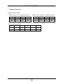
1
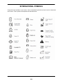
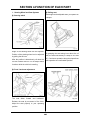
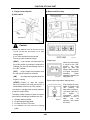
SLOPE MOWER
0
TO THE OWNER:
This manual contains information concerning operation, adjust, and maintenance of the SG280 Mower.
You have purchased a dependable machine, but only by proper care and operation you can expect to
receive the performance and long service built into this Mower. Please have all operators read this
manual carefully and keep the manual available for reference.
Your SHIBAURA dealer will instruct you in the general operation of your Mower. (Refer to the "Delivery
Report" at the back of this manual.) Your dealer's staff of factory-trained service technicians will be glad
to answer any questions that may arise regarding the operation of your Mower.
Your SHIBAURA dealer carries a complete line of genuine SHIBAURA parts. These parts are
manufactured and carefully inspected to insure high quality and accurate fitting of any necessary
replacement parts.
Keep this manual next to your machine, after you have read through it. If you lose or damage this
manual, ask a new manual to SHIBAURA' s dealer right away.
CAUTION: THIS SYMBOL IS USED THROUGHOUT THIS BOOK WHENEVER PERSONAL
SAFETY IS INVOLVED. TAKE TIME TO READ AND FOLLOW THE INSTRUCTIONS. BE
CAREFUL!
CAUTION: PICTURES IN THIS MANUAL MAY SHOW PROTECTIVE SHIELDING OPEN OR
REMOVED TO BETTER ILLUSTRATE A PARTICULAR FEATURE OR ADJUSTMENT.
BE CERTAIN, HOWEVER, TO CLOSE OR REPLACE ALL SHIELDING BEFORE OPERATING THE
MACHINE.
IMPROVEMENTS
IHI-SHIBAURA is continually striving to improve its products. We reserve the right to make
improvements or changes when it becomes practical and possible to do so, without incurring any
obligation to make changes or additions to the equipment sold previously.
1
CONTENTS
SECTION 1-SAFETY RULES ·································································3
SECTION 2-GENERAL INFORMATION··············································· 11
SECTION 3-NAME OF EACH PART ···················································· 14
SECTION 4-FUNCTION OF EACH PART ············································ 16
SECTION 5-CHECK BEFORE OPERATION········································ 23
SECTION 6-DRIVING AND WORK ······················································25
SECTION 7-MAINTENANCE AFTER WORK······································· 33
SECTION 8-INSPECTION AND MAINTENANCE ································ 35
SECTION 9-TROUBLE SHOOTING ····················································· 49
SECTION 10-CONSUMABLE PARTS·················································· 52
2
SECTION 1-SAFETY RULES
1. SAFETY RULES
4) Never use the Slope Mower.
Please pay particular attention to all boxed parts
in the text which have the sign .
- When people, especially children, or pets are
nearby.
This sign warns you to be careful when carrying
out certain functions.
- If the operator has taken medicine or
substances that can affect his ability to react
and concentrate.
DANGER:
Denotes immediate hazards which WILL result in
severe personal injury or death.
5) Keep in mind that the operator or user is
responsible for accidents or hazards
occurring to other people or their property.
WARNING:
Denotes a hazard or unsafe practice which
COULD result in severe personal injury or death.
6) Do not carry passengers.
7) The operator of a Slope Mower must carefully
follow the driving instructions, particularly:
CAUTION:
Indicates important safety messages in this
manual. When you see this symbol, carefully
read the message that follows and be alert to the
possibility of personal injury or death.
- The need for care and concentration when
using Slope Mowers;
NOTE: Gives helpful information.
- That control of a Slope Mower sliding on a
slope will not be regained by the application
of the brake.
Labels attached to certain parts of the Slope
Mower give important safety information.
The main reasons for loss of control are:
Please read them carefully. Should a label
detach itself or become illegible, contact your
dealer for a replacement.
- Insufficient wheel grip;
- Being driven too fast;
- Inadequate braking;
SAFETY INSTRUCTIONS
- The type of machine is unsuitable for its task;
A) TRAINING
1) Read the instructions carefully. Be familiar
with the controls and the proper use of the
equipment. Learn how to stop the engine
quickly.
- Lack of awareness of the effect of ground
conditions, especially slopes;
- Incorrect hitching and load distribution.
8) The Slope Mower is equipped with a series of
safety microswitches and devices which
must never be removed, altered or tampered
with. Removing these devices invalidates the
warranty and the manufacture declines any
responsibility.
2) Only use the Slope Mower for the purpose for
which it was made, that is, the cutting of
grass. Any use not specifically indicated in
the instruction handbook can be dangerous
and result in damage to the machine, and will
also result in the annulling of the warranty and
the manufacturer declining all responsibility.
B) PREPARATION
3) Never allow children or people unfamiliar with
these instructions to use Slope Mower. Local
regulations may restrict the age of the
operator.
3
1) While mowing, always wear substantial
footwear and long trousers. Do not operate
the equipment when barefoot or wearing
open sandals.
SAFETY RULES
2) Thoroughly inspect the area where the
equipment is to be used and remove all objects
which may be thrown by the machine (stones,
sticks, metal wire, bones, etc.)
3) WARNING: Engine fuel is highly flammable:
5) Do not operate on slopes of more than
22°(40%) in basic configuration.
This machine will operate on more than
22°slopes. This is in conjunction with operator
training, correct weight, correct maintenance
of the machine and appropriate conditions.
- Store fuel in containers specifically designed for
this purpose.
6) Remember there is no such thing as a “safe”
slope.
- Refuel using a funnel and outdoors only. Do
not smoke while refuelling or whenever
handling the fuel.
Travel on grass slopes requires particular
care. To guard against overturning:
- Add fuel before starting the engine. Never
remove the cap of the fuel tank or add fuel
while the engine is running or when the engine
is hot.
- If fuel is spilled, do not attempt to start the
engine but move the machine away from the
area of spillage and avoid creating any source
of ignition until the fuel has evaporated and the
fumes dispersed.
- Tighten caps of all fuel tanks and containers
securely.
4) Replace faulty silencers.
5) Use the step plates when getting on and off the
machine to prevent falls. Keep steps and
platform clear from mud and debris.
6) Always check overhead clearance, especially
when transporting this machine.
C) OPERATION
- Do not stop or start suddenly when going up
or downhill;
- Always keep the machine in gear, especially
when traveling downhill;
- Machine speeds should be kept low on
slopes and during tight turns;
- Stay alert for humps and hollows and other
hidden hazards;
- Never mow across the face of the slope.
7) Stop the blades rotating before crossing
surfaces other than grass. When moving the
Mower away from the lawn disengage the
blades and put the mower deck into the
highest position.
8) Do not change the engine governor settings
or overspeed the engine. Operating the
engine at excessive speed can increase the
hazard of personal injury.
9) Before leaving the operator’s position:
1) Do not operate the engine in a confined space
where dangerous carbon monoxide fumes can
collect.
- Disengage the
Mower-deck.
blades
and
lower
the
- Shift into neutral and set the parking brake.
2) Mow only in daylight or good artificial light.
- Stop the engine and remove the key.
3) Avoid operating the equipment in wet grass,
where feasible.
10) Disengage blades, stop the engine and
remove key:
4) Before starting the engine, disengage the
blades, shift into neutral and engage the
parking brake.
4
- Before carrying out any work beneath the
cutting deck or unclogging the chute;
SAFETY RULES
- Before checking, cleaning or working on the
Slope Mower;
- After striking a foreign object. Inspect the Slope
Mower for damage and make repairs before
restarting and operating the Slope Mower;
- If the Slope Mower starts to vibrate abnormally
(immediately check and remove the cause of
the vibration)
11) Disengage drive to blades when transporting or
not in use. Disengage the blades and wait for
them to stop before emptying the grasscatcher.
12) Stop the engine and disengage blades:
- Before refuelling.
- Every time the grass-catcher is removed or
replaced.
19) Keep the machine in the same travel speed
when going downhill as used when going
uphill. Do not coast or free wheel down hills.
20) Watch where you are going especially at row
ends, on roads, around trees and low hanging
obstacles.
21) Do not cross gravel roads with the PTO
engaged.
22) Look to the rear before and when reversing.
You must disengage blades before shifting
into reverse. Before reversing make sure the
area behind you is clear of obstructions, holes
and small children. Use extra caution when
machine is equipped with a grass catcher.
23) Do not tow this machine. Use are suitable
truck or trailer when transporting on public
roads.
- Before making height adjustment.
13) Reduce the throttle setting during engine shut
down and turn the fuel off at the conclusion of
mowing, following the instructions in the
handbook.
14) Do not put hands or feet near or under rotating
parts. Keep clear of the discharge opening at all
times.
24) Before mounting or operating the mower
deck ,read and understand the mower deck
manual.
D) MAINTENANCE AND STORAGE
15) Watch out for traffic when crossing or near
roadways.
1) Keep all nuts, bolts and screws tight to be
sure the equipment is in safe working
condition. Regular maintenance is essential
for safety and for maintaining performance
levels.
16) When using any attachments, never direct
discharge of material toward bystanders nor
allow anyone near the machine while in
operation.
2) Never store the equipment with fuel in the
tank inside a building where fumes may reach
a flame or a spark or a source of extreme
heat.
17) Do not park this machine on a steep incline.
3) Allow the engine to cool before storing in an
enclosed space.
18) Do not wear loose clothing when operating the
power take-off, or when close to rotating
equipment.
5
4) To reduce the fire hazard, keep the engine,
exhaust silencer, battery compartment and
fuel storage area free of grass, leaves, or
excessive grease. Always empty the
grass-catcher and do not leave garden
rubbish containers within a room.
SAFETY RULES
5) Check the deflector and grass-catcher
frequently for wear and deterioration.
17) Never perform service underneath
machine if it is not completely stable.
6) For reasons of safety, do not use the equipment
with worn or damaged parts.
Parts are to be replaced and not repaired.
Use genuine spare parts. Parts which are not of
an equivalent quality can damage the
equipment and could be dangerous for your
safety.
18) Be careful of Hot Oil Under High pressure.
The hydraulic system for the implement
operates under high pressure. When
replenishing or draining hydraulic oil, be sure
to first relieve the high pressure.
7) If the fuel tank has to be drained, this should be
done outdoors and when the engine is cool.
8) Wear strong work gloves when removing and
reassembling the blades.
9) Check the blades’ balance after sharpening.
10) Take care as the rotation of one blade can
cause the other blade to turn.
11) When the machine is to be parked, stored or left
unattended, lower the mower deck.
12) The ignition key must never be left inserted in
the machine, or where children or persons not
familiar to the machine may reach them.
Before any maintenance or repair, remove the
ignition key.
13) Conduct operation and inspection during
daytime or under bright lighting.
14) Stop engine before servicing ,adjusting ,
repairing this machine.
15) Do not work under a raised attachment unless it
is securely supported by a suitable hoist or floor
jack and multiple jack stands.
16) When you work under the machine, support it
firmly with such a crane, hoist or rigid racks on a
level place. If not It may cause severe
accidents.
the
19) Be sure to disconnect the (-) terminal of
battery before servicing. If not short circuit
may cause a fire.
20) HANDLING BATTERY ELECTROLYTE
- The battery electrolyte is diluted sulfuric acid
and poisonous. Top up battery electrolyte in
well ventilated area and wear eye protection
and rubber gloves. Splashed solution can
cause burning skin, clothes and blindness if it
get into eyes.
21) Do not modify or alter or permit anyone else
to modify or alter this machine or any of its
components and functions without first
consulting SHIBAURA’s Dealer.
E) TRANSPORTING
The method of loading & un-loading on the
truck Please do the loading and unloading work
on the flat & safety place.
1) Loading on the truck
- Stop the truck engine and set the parking
brake.
- Put the hook of the ramps on the truck floor
firmly so that the ramps will not come off.
- Load the tractor vehicle into truck slowly by
moving the vehicle forward. (* in case that the
implement of installation is mower deck)
- Load the tractor vehicle into truck by moving
the vehicle forward on the ramps.
6
SAFETY RULES
- After the completion of loading, lower the
implement. Then, stop the tractor engine and
set the parking brake (for tractor).
- Fix the tractor vehicle with a strong rope.
2) Unloading on the truck
- Please do the unloading work under the
opposite procedure of loading
3) Warning
- Set the parking brake for truck.
- Remove the mud from the tractor tires in order
to prevent vehicle from slipping sideways on
the ramps. There is a possible risk of fall of
vehicle due to accidental movement of ramps
during loading work.
- Put the hook of the ramps on the truck floor
firmly. There is a possible risk of fall of the
vehicle due to accidental movement of the
ramps during loading work.
- Keep the even height between right and left
ramps. There is a possible risk of fall of the
vehicle due to accidental movement of the
ramps during loading work.
- Do not steer sharply on the ramps.
There is a risk of fall of the vehicle due to
accidental movement of the ramps during
loading work.
- Pay attention to loading & un-loading in order
not to loose the vehicle's balance when moving
the vehicle on the gap (seam) between the
ramps and truck floor.
Keep those works at slow speed. There is a
possible risk of fall of the vehicle.
- Fix the vehicle tire & bumper and drawbar hitch
with a strong rope firmly. There is a possible
risk of accidental movement of cargo during
transportation.
7
- In case of using sunshades cover etc, please
fix it with the ropes etc firmly. There is a
possible risk of deformation or part detach or
fall on the vehicle part, which tends to be
affected by wind pressure.
- Do the loading work slowly by moving the
vehicle forward. If loading work is done by
moving the vehicle backward, the vehicle's
rear tire tends to float and as a result, there is
a possible risk of fall of vehicle However, in
case that the rear visibility is not good due to
the rear installation implement, please do the
loading by moving the vehicle backward,
considering the possible any difficulties and
fall of vehicle on the unloading.
- Assure that the height of the cargo will not be
problem at the height restriction area to avoid
danger to other traffic.
ENVIRONMENTALLY RESPONSIBLE
ALWAYS BE ENVIRONMENTALLY
RESPONSIBLE
- Follow the guidelines of the government
agency for the proper disposal of hazardous
materials such as engine oil, diesel fuel,
engine coolant and, machine fluid, grease.
- NEVER dispose of hazardous materials
irresponsibly by dumping them into a sewer,
on the ground, or into ground water or
waterways.
- Failure to follow these procedures may
seriously harm the environment.
- Comply with legal regulations and guidelines
for disposal of empty containers for fuel,
cooling water (coolant),oil, grease; fuel/oil
filters; batteries; machine itself; machine
accessories; and packaging materials.
SAFETY AND INSTRUCTION DECALS
Your Slope-mower must be used with care.
Therefore, decals have been placed on the
machine, to remind you pictorially of main
precautions to take during use. Their meaning is
explained below.
We also strongly recommend to carefully read
the safety instructions given in the concerned
chapter of this manual.
• Never touch rotating parts while engine is
running.
SAFETY DECALS
MAX 30°
30°
• Stay clear of hot surface.
• Read this Operator’s Manual before using the
Slope-mower.
• Keep other people at a distance while using.
• Make sure that children stay clear of the
machine all time when engine is running.
• Do not use this machine on slopes greater than
30°. Specialist training is recommended.
• Use diesel fuel.
• Diesel fuel is flammable.
• Add diesel fuel before starting the engine.
• Batteries produce explosive gas. Keep sparks
and flames away.
• Never remove the fuel tank cap or add diesel
fuel while the engine is running or when the
engine is hot.
• Battery contains sulfuric acid. Wear protective
clothing and use eye protection.
• Refuel outdoors only and do not smoke while
refuelling.
8
SAFETY AND INSTRUCTION DECALS
INSTRUCTION DECALS
②
①
• Do not open when hot.
• Contents under pressure.
③
Parking Brake
① Parking Brake
② “Lock” Position
③ “Release” Position
• Always wear seat belt.
Key Switch
①
②
③
④
• Do not attach ropes or chains to ROPS for
pulling purposes.
Use of ROPS and seat belt reduce the
chance of injury or death if rollover or upset
occurs.
9
Engine “HEAT” Position
Engine “STOP” or “OFF” Position
Engine “ON” Position
Engine “START” Position
SECTION 2-GENERAL INFORMATION
MACHINE IDENTIFICATION PLATE
①
②
③
④
⑤
⑥
⑦
CE Conformity Mark
Weight in kgs
Name and Address of Manufacturer
Type of Front Mower
Serial Number
Engine Power
Engine Number
④
⑤
③
⑦
⑥
②
10
①
GENERAL INFORMATION
PLEASE READ CAREFULLY:
For a complete list of the pre-delivery service
checks performed by your dealer, refer to the
PRE-DELIVERY SERVICE checklist found at the
back of this manual. Keep one copy as your record
of the service performed. The other copy should be
removed from the manual and kept by your dealer.
MAKE SURE THAT BOTH COPIES ARE
COMPLETED AND THAT YOU AND THE
DEALER SIGN BOTH COPIES.
A PRODUCT IDENTIFICATION PLATE is located
in the front frame of the mower.
The numbers on the plate are important in the
event your mower should require future service.
For your convenience, have your dealer record
these numbers in the appropriate spaces below.
IHI Shibaura Machinery Corporation is continually
striving to improve its products. We reserve the
right to change prices, specification, or equipment
at any time without notice.
All data given in this book is subject to production
variations.
Dimensions
and
weights
are
approximate only, and the illustrations do not
necessarily depict Mower in standard condition.
For exact information about any particular Mower,
please consult your SHIBAURA dealer.
This Mower has been designed for doing light work,
such as mowing, blowing snow. Do not attempt to
use implements that were not designed for this
mower, as they may cause damage to the mower.
11
Fig.1-1
GENERAL INFORMATION
MINIMUM HARDWARE TIGHTENING TORQUES
IN FOOT POUNDS (NEWTON-METERS) FOR NORMAL ASSEMBLY APPLICATIONS
METRIC HARDWARE AND LOCKNUTS
GENERAL INFORMATION
12
INTERNATIONAL SYMBOLS
As a guide to the operation of your tractor, various international symbols have been used on instruments
and controls. These symbols are depicted and described below.
13
SECTION 3-NAME OF EACH PART
1. Vehicle
Fig. 3-1
Fig. 3-2
14
NAME OF EACH PART
2. Operation System
Fig. 3-3
Fig. 3-4
15
SECTION 4-FUNCTION OF EACH PART
1. Steering Wheel and Seat Systems
③ Rolling seat
Seat angle can be adjusted when you operate on
① Steering wheel
a slopes.
Angle of the steering wheel can be adjusted.
Position of the steering wheel can be adjusted
By grasping the seat swing lever above the oil
tank, the seat rolls laterally in 2 steps to 12.5 and
by pulling the tilt lever.
After the position is determined, pull down the
tilt lever forward and fix. Do not adjust these
15°. Continuous operation along the slope allows
safe operation at a comfortable position.
functions while the vehicle is traveling.
② Front / back seat adjustment
The
seat
slides
forward
and
backward.
Release the seat by movement of the lever.
Adjust the seat properly to your operating
position.
16
FUNCTION OF EACH PART
④ Seat belt (ROPS)
DO NOT ATTEMPT BYPASS SEAT SAFETY
INTERLOCK SWITCH.
Seat Belt
● When driving the vehicle, always fasten the
seat belt.
● Fasten the seat belt extending over the hips.
If the seat belt is not applied, death or serious
injury may be caused in the event of roll over,
tumbling, rear end collision or other
accidents.
● DO NOT remove a ROPS and seat belts.
ROPS when used with seat belts is effective in
reducing injuries during unit overturn
accidents.
● Over turning the unit without a ROPS can
result in serious injury or death.
● ROPS is used to reduce damages of accidents
in the event of roll over of the vehicle and not
to prevent the roll over.
ROLL OVER PROTECTIVE STRUCTURE
● Do not drive the vehicle with the safety frame
removed.
(ROPS)
Roll Over Protective Structure (ROPS) and
● Do not modify the safety frame. If modified, it
does not function as a safety frame.
seat belts are standard equipment.
● If ROPS is damaged or bent so that its strength
is influenced, replace the safety frame.
If it is repaired, it may not function as ROPS.
17
FUNCTION OF EACH PART
2. Engine Control System
② Meters and Pilot Lamp
① Main switch
Caution
● While the machine is not in service, be sure
to pull out the key and store it in a safe
storage place.
If not, some accident may be caused.
The key is used to start the engine.
[HEAT]
If you release your hand from the
key at the position to preheat the combustion
chamber, the key will automatically return to
the “OFF” position.
• Charge lamp
[OFF]
Engine stops at this position and
the key may be inserted or removed.
Fig. 4-10
[ON]
Key stays at this position while the
engine is running.
[START] Position to start the engine.
When you release your hand from the key, it
automatically returns to the “ON” position.
• Engine water temperature warning lamp
The vehicle is equipped with 4 safety switches
to start the engine safely.
The safety switch functions to start the engine
only when the following 4 conditions are met:。
1.
2.
3.
4.
When the main switch
is turned to the “ON”
position, the lamp
lights up. After the
engine starts, number
of engine revolutions
increases.
When
charging is started, the
lamp goes out.
Operator takes is seated.
He presses the brake pedal.
He turns OFF the PTO clutch.
He releases his foot from the running
pedal.
Fig. 4-11
18
Even though the main
switch is turned to the
“ON” position, the
lamp does not light up.
The lamp lights up if
the
engine
is
overheated
during
operation. In such a
case,
stop
the
operation and check
the cause.
FUNCTION OF EACH PART
• Engine oil pressure pilot lamp
When the main switch
is turned to the “ON”
position, the lamp
lights up.
When
the
engine
starts operation, the
lamp goes out. If the
lamp lights up while
Fig. 4-12
the engine is rotating,
there is a fault in the
lubrication
pressure
circuit.
Stop
the
engine
immediately and check
for the trouble.
• Engine rev. counter / elapsed time integrator
• Glow lamp
While the engine is running, its number of
Fig. 4-13
By setting the main
switch to the “Glow”
position, the lamp
lights up indicating that
the power is supplied
to the heater. Keep the
switch at the “Glow”
position for about 5
seconds and then turn
it to the “START”
position to start the
engine.
Fig. 4-15
revolutions is indicated by the pointer. The
elapsed time integrator indicates the time by a
number for which the machine was operated.
By multiplying the white number on the right
by 6, time in the minute unit is obtained.
③ Accelerator lever
• Water temperature meter
Fig. 4-14
Temperature of cooling water is indicated by a
The accelerator lever is used to increase or
pointer during operation.
decrease the engine revolutions.
When the pointer points to the “H” position,
By pulling the lever toward the operator, the
engine may be overheated. Stop operation
engine revolutions decrease and by pushing it
even when the engine water temperature
forward, the engine revolutions increase.
meter lamp does not light up and check for the
cause.
19
FUNCTION OF EACH PART
3. Traveling and Mower Clutch System
③ Parking brake lever
① Gear shift lever
Used to park the vehicle.
Used to change the traveling speed.
Vehicle speed can be selected from “L” (low
By pressing the brake pedal fully and pulling up
speed) (4 WD) and “H” (high speed) (2 WD).
the lever, the parking brake is applied.
By pushing the lever forward, the speed
To release the brake, press the brake pedal and
increases and by pushing it rearward, the
release the brake pedal while pushing down the
speed decreases. Keep the lever on the low
lever.
speed side for usual operation and use the
high speed side only when traveling. When
changing the speed, stop the vehicle.
② Brake pedal
Warning
●
Used to stop the vehicle.
When warming up the vehicle, be sure to
apply the parking brake.
By pressing the brake pedal, brake is applied.
A safe starting device is provided. Be sure to
press the brake pedal when starting the
engine.
20
FUNCTION OF EACH PART
④ Forward/reverse pedal
⑤ PTO clutch lever
Pedal to travel the vehicle.
Lever to engage to the mower and rotate the
blades.
Press forward pedal down to drive the vehicle
forward and the reverse pedal to reverse it.
No clutch pedal is provided on this machine.
Speed is increased or decreased by the
By moving the PTO clutch lever to “ON”, the
amount the pedal is depressed.
blades rotate. By moving the PTO clutch lever to
Speed of the vehicle when starting to travel
“OFF”, the clutch is disengaged and the blade
varies depending on the traveling pedal
stops rotating.
pressing degree. When starting the vehicle,
The PTO clutch lever tensions the belt. When
press down the pedal gradually and slowly. By
engaging the clutch, move the lever slowly to
releasing your foot from the pedal on a flat
“ON”. A safe starting device is provided. Always
ground, the pedal automatically returns to the
start the engine at the “OFF” position.
neutral position and the vehicle stops.
A start-up safety device is provided. When
starting the engine, never press the pedal.
Warning
Always keep the clutch lever at the “OFF”
position except during the operation. Do not
travel with the blade rotating as pebbles or some
other objects may be thrown into the surrounding
area and are dangerous. When the PTO clutch
lever is turned to the “OFF” position, the PTO
does not stop immediately. It takes some time to
stop. Do not put your hand or other objects into
the mower inside until the rotation stops
completely.
21
FUNCTION OF EACH PART
4. Hydraulic System
① Mid mower lifting lever
Used to lift or lower the mower.
By pushing down the lever rearward, the
mower rises. When you release your hand
from the lever, it automatically returns to the
neutral position. By setting the lever to the
lowering position, the lever is held at the
lowered position and the mower becomes free
to float over undulating ground.
22
SECTION 5-CHECK BEFORE OPERATION
Caution
Danger
●
●
Always stop the engine and apply the
heated muffler, engine and other parts have
services or adjustment.
completely cooled down. If not, you may be
While the engine is running or hot, never
burnt.
●
When removing covers or other components
Do not hold a cigarette in your mouth or
for inspections or services, always reinstall
use a naked flame when supplying fuel.
them. If not, you may touch a running part of
After refueling, tighten the fuel cap firmly
the machine and you will be injured.
and wipe away spilled fuel.
●
Carry out inspections and services after the
parking brake before starting inspections,
top up the oil as you may be burnt.
●
●
Ignoring this
caution may lead to a fire.
1. Physical Condition and Clothes of Worker
If the fuel pipe is damaged, fuel may leak.
① Physical condition
Be sure to check damages of the fuel pipe.
When doing inspections or services, you should
If not, a fire may be caused.
be in good health. If you cannot concentrate your
attention on your work due to fatigue, sickness,
drug influence or other, you should not work on
Warning
the machine. In particular any person who is
●
To secure safe and comfortable working
under the influence of alcohol, pregnant or under
conditions, the operator of this machine
18 years old should not work on, or with the
should perform the start-up inspection
machine.
every day. Defects should be immediately
●
repaired. Check also after shut down to find
② Clothes
any abnormalities.
●
Carry out inspections and maintenance
may be caught by the operation levers or
services in a flat and stable place where
machine parts.
there is no traffic danger or the machine
●
may not fall over or move when using a
jack.
If
these
precautions
are
not
●
Wear a helmet.
observed, the machine may fall over or
●
Wear protective glasses, mask, gloves, and
other protective apparatus as required.
If you should perform start-up inspections
and services with the engine running, avoid
a closed space.
●
4
You should wear protective shoes with
slip-resistant shoes.
other accident may happen.
●
You should avoid so loose clothes that you
During the start-up inspections, keep any
persons (particularly children) away from
the workplace.
23
CHECK BEFORE OPERATION
2. Inspection Method
Users of this machine should perform start-up inspection before starting operation every day to ensure
safe and comfortable operation, according to the procedure below.
if any, immediately.
Correct extraordinary conditions,
If any problems are felt during operation, inspect and repair without delay.
① Go around the machine to see:
Reference page
●
Air pressure, wear and damage of tires····························································
47
●
Looseness of bolts fixing the wheels ································································
47
●
Fuel level, fuel leakage, damage of fuel pipe ···················································
38
●
Level in the oil tank, contamination or leakage of oil·········································
39
●
Battery electrolyte level ····················································································
43
●
Deformation, damage or stain of each part
●
Damage of various parts of vehicle body, looseness of bolts
② Open the bonnet to see:
Reference page
●
Level and contamination of engine oil, fuel leakage ·········································
38, 40
●
Level of cooling water, water leakage, damage of hose ···································
42
●
Condition of the air cleaner ··············································································
43
●
Insufficient tension or damage of cooling fan belt ·············································
45
●
Dust or grass on the radiator grill or in the engine area ····································
46
●
Condition of wiring loom and sheathing, loose connections······························
③ Sit on the driver’s seat and check:
Reference page
●
Brake operating condition ················································································
47
●
Traveling pedal operating condition··································································
21
●
Allowance of steering wheel·············································································
31
④ Start the engine and check:
Reference page
●
Colour of exhaust gas ······················································································
47
●
Operation of lamps and meters ········································································
18, 19
●
Noise or vibration after the engine is started
24
SECTION 6-DRIVING AND WORK
1. Break-in Operation (first 50 hours)
2. Starting and Stopping the Engine
Warning
Handling of a new vehicle in the initial 50 hours
is very important.
Break-in operation greatly influences the life
and performance of machines.
●
When starting the engine, sit down on the
Handle the
driver’s seat and check the lever position and
machine correctly paying attention to the
safety of surroundings. If not, injury accidents
following points particularly during this period.
may be caused.
●
Do not start the engine in a closed space.
(1)
Avoid quick starting and quick stopping.
Start the engine outdoors. If you are required
(2)
Avoid higher speed or heavier load.
to start the engine in a room, ventilate the
(3)
Drive the vehicle after the engine has
area sufficiently. If not, you may suffer
been sufficiently warmed.
poisoning of exhaust gas, which may lead to
Drive slowly on rough roads or sloping
an accident involving death.
(4)
lands.
(5)
When initial 50 hours have elapsed,
perform the inspection of each part and
Caution
change the oil according to “1. Periodical
Inspection List” on page 36.
●
Before and after the operation of the
machine, always perform inspections and
services. Particularly, take care of the brake,
levers and other operating devices to ensure
their
positive
operation.
If
not,
injury
accidents or machine failure may result.
●
Apply the parking brake during the warming
up operation. If not, the machine may start
moving and cause an accident.
25
DRIVING AND WORK
① Starting the engine
● The starter consumes large current. Never
operate it continuously for more than 10
seconds. (If the engine is not started within
10 seconds, turn off the switch, wait for more
than 1 minute and then repeat the starting
procedure again.)
● Never turn the key switch to the “starting
position” while the engine is running.
(1) Pull up the bonnet cover.
(2) Set the fuel strainer tap to the “O” (open)
position.
[Reference:]
● This machine is hydraulically operated. If you
do not carry out the warming-up operation,
the hydraulic system may fail and may cause
accidents. Particularly in cold areas, when
the air temperature deceases and it grows
colder, oil viscosity increases so that
hydraulic operation may delay or normal
pressure may not be obtained. To prevent
such troubles, always carry out warming-up
operation a little longer referring to the values
in the table below.
Air temperature
0°C – -10°C
-10°C – -20°C
Under -20°C
Warming-up time
More than 10 minutes
More than 20 minutes
More than 30 minutes
② Stopping the Operation
(1) Set the accelerator lever to the “Low speed
operation” position and turn the key switch
to the “OFF” position. The engine will stop.
3. Raising and Lowering the Mid Mower
(3) Sit in the seat (seat switch is provided).
(4) Set the accelerator lever between the
“Idling” and “Highest speed” positions.
(5) Turn the key switch to the “Glow” position
(keep it there for about 5 seconds).
(6) Press the brake pedal fully and turn the key
switch to the “START” position.
(7) When the engine is started, release the
ignition key immediately.
[Reference]
● Because of the function of the safety switch,
the starter motor rotates only when; you are
seated, the mower clutch lever is at the “Off”
position, and the brake pedal is fully
depressed. The forward/reverse pedal is not
pressed.
(8) Decrease the engine speed down to about
1500 rpm with the accelerator lever and
keep the warming up for about 5 minutes
with no load.
When lifting or lowering the mid mower, push
the lifting lever forwards to lower the mower,
and push it to the rear to lift the mower. When
you leave your hand from the lever, it
automatically returns to the neutral position.
When lowering the mower keep the lever in the
forward position for 2-3 seconds after the
mower is lowered. This allows the mower to
float freely.
26
DRIVING AND WORK
4. Starting, Turning and Stopping Method
③ Stopping and Parking
Warning
●
When starting the vehicle, check for people
around the vehicle, confirm safety in the
surrounding areas and start the vehicle
slowly avoiding an abrupt start. Failure to
do this may result in injury or may cause
accidents.
Warning
●
When you leave the vehicle, park it on solid,
flat and stable ground.
●
If you are required to park the vehicle on a
slope, park the vehicle sideways and apply a
chock to the front wheels.
●
●
●
During operation or when moving the
vehicle, wear a helmet for safety.
Do not allow anybody other than the driver
to get on the vehicle.
Do not start, turn or stop the vehicle
abruptly or do not drive the vehicle too fast.
Operate it slowly.
(1) Release your foot from the forward or
reverse pedal and press the brake pedal.
(2) Lower the implement fully.
(3) Apply the parking brake.
Warning
① Starting
(1) Shift the gear shift lever to a desired
position.
(2) Lift the mower with the lifting lever.
(3) Push down the parking brake pedal to
release the parking brake.
(4) By pressing forward or reverse pedal, the
vehicle starts moving.
[Caution for Handling]
● Stop the vehicle before moving the gear
lever. Operating the lever while the vehicle
is moving may cause a failure.
5. Work Operation
●
before commencing work. Obstacles may
damage the mower and the vehicle, as well
as the mower blade.
●
body.
●
Do not direct the discharge outlet to people.
Grass or stones may be discharged and
injure them.
Warning
●
Do not run the mower in raised condition. It is
dangerous and may damage the mower
② Turning
●
Remove obstacles in the area to be cut
Before turning the vehicle, decrease the
speed sufficiently. If the vehicle turns at a
high speed, it may turn over and an injury
accident may result.
When making a turn, ascertain the ground
condition before turning.
27
DRIVING AND WORK
① Caution for mower operation
(1) If you operate a mower for the first time or
are not familiar with machines, learn how to
operate it on a flat place before
commencing work.
(2) Select a proper method of mowing
operation according to the size or shape of
the field, and arrangement of trees and
other obstacles.
(3) Height of grass varies depending on the
type. Most grass is mowed to 51 to 76 mm
high. Avoid mowing more than 1/3 of grass
height to avoid damage of the grass.
If the turf grass is excessively tall, mow it to
a little higher length and then to a desired
height.
(4) If the grass is thick, or in case of grass in
the spring season or in a place of soft
ground surface, the vehicle or mower
wheel may settle into the ground so that the
grass may be mowed too short. Check the
height and adjust it when necessary.
② Operating the mower clutch lever
Power to the mower is turned ON or OFF with
the mower clutch lever. By pulling up the lever,
power is turned ON and the mower starts
rotating. Keep the switch at this position during
operation. By pushing down the switch
forward, the power is turned OFF and the
mower stops rotating.
[Caution for Handling]
● Before operating the mower clutch lever,
pay attention to the surroundings and
ascertain the safety.
● When starting the engine, set the mower
clutch lever to the “OFF” position. If not, the
safety device is activated and the engine
does not start.
●
●
If the engine revolving speed is too low,
mower operation cannot be started. Operate
the engine at full throttle for mowing.
When the mower clutch lever is set to “OFF”,
the mower blades do not immediately stop.
You should be careful while the mower is
revolving.
③ Lawn mowing operation
For more efficient mowing operation, blade
revolution should be always kept at the highest
speed. By setting the accelerator lever of the
vehicle to the highest revolution position, the
blade highest speed and engine highest output
can be obtained. Select the vehicle operating
speed according to the turf condition, finish and
skill of the operator. It is usually 3 to 6 km/h. You
should operate the lawn mower in a gentle
manner.
④ Lawn mowing on sloping land
Warning
●
Do not operate the mower in a place where
overturn or slip is feared. Vehicle may slip
more easily particularly after rain, for
instance. Do not operate the mower under
such a condition.
● When working on a sloping ground, check for
holes, rocks, roots of trees or other obstacles
and check the entire land features in
advance.
● On a sloping land, advance along contour
lines and make a turn at a place of gentle
angle of gradient.
To operate on slopes between 25 - 30 degrees
operator training is required. Also the machine
must be correctly maintained and must be used
in appropriate conditions.
28
DRIVING AND WORK
⑤ Discharge of grass
⑥ Points of issues and solution
●
Warning
Uneven mowing
Uncut turf remains in rows because of wear
or deformation of the blade or too low engine
●
●
●
Grass clippings are forcefully discharged.
speed. Check the blade for length, wear or
For safety, keep the discharge outlet cover
deformation, or engine speed and operation
always in position.
speed.
Do not direct the discharge outlet to people
●
Separation of turf
during operation.
Turf or ground is partially scraped off when
Before removing grass from the mower, be
the blade is too low. Check the blade height,
sure to stop the engine and wait for the
for foreign substances entangled in the
blades to stop rotating.
blades,
blade
installing
condition,
tyre
pressures, etc. in such a case.
This mower is designed to discharge grass
●
Partial residue
after being cut evenly. When cutting tough,
If some grass remains uncut, check for too
thick or tall grass, significant load is applied to
low engine speed, a build up of grass in the
the mower. Decrease the forward speed or
mower deck, too high running speed, and slip
mowing width in such a case.
of clutch belt or mower belt.
●
Wavy cutting
[Caution for Handling]
Difference of turf density or grass height,
Keep the mower main body and inside of the
unevenness of ground surface, or other
discharge outlet cover clean for smooth
problems of the area to be cut may be the
discharge.
cause. Check that the mower gauge wheels
are in contact with the ground, build up of
grass in the cutter deck, wear or deformation
of blade or traveling speed.
●
Uneven mowing height
Cause is different mowing height between
right and left sides. Check the mower gauge
wheel for correct height of cut position,
deformation of blade and blade shaft, blade
installing direction, or even air pressure of
right and left tires of the vehicle, in such a
case.
29
DRIVING AND WORK
6. Loading onto and Unloading from Truck
Warning
●
When
loading
the
vehicle
onto
or
unloading from a truck, stop the truck
engine, apply the hand brake to prevent
the truck from moving and apply a chock
to the vehicles wheel. Park on a flat place
where the traffic is safe.
●
<Loading>
(1) Raise the implement to a height not to allow
the implement to touch the loading ramps.
(2) Position the implement straight to the loading
ramps and load it slowly.
(3) Operate the steering wheel carefully so not to
allow the wheels from coming off the ramps.
(4) After completion of loading, lower the cutter
deck until it comes into contact with the bed
of the vehicle, turn OFF the main switch and
fix the vehicle firmly with ropes.
length and strength and not slipping easily.
<Unloading>
(1) Unload the vehicle in the reverse order to
loading.
Hitch a hook positively to the deck of the
② Transportation method
Select loading ramps of enough width,
truck to prevent the loading ramps from
Warning
getting out of place.
●
When loading the vehicle onto a truck,
drive the vehicle in reverse.
●
●
Remove mud, etc. from the tire to prevent
the vehicle from side slipping on the
loading ramps.
●
Never change the course on the loading
ramps. If change of course is required, get
down from the loading ramps and restart.
Caution
●
① Loading and Unloading with Ladders or
Lamps
< Specifications for loading ramps>
●
Length: ···· More than 3.5 times the height
of the loading space of the truck
●
Width: ······ More than 40 cm
●
Strength: ·· Should withstand the weight of
2000 kg.
●
Surface should have a non-slip surface.
●
The loading ramps should not be laterally
Fix the vehicle firmly with strong ropes.
Lower the cutter deck until it comes into
contact with the bed of the vehicle. If not,
when the truck brakes suddenly, the mower
may fall off the vehicle leading to an injury
accident.
uneven in height. Install the walkway
positively to the center of the loading space
of the truck to ensure even right and left
length.
30
When carrying the vehicle on the truck, fix
the bonnet with a locking catch and lock pin
to prevent it from opening. If not, the cover
may be opened by wind, and cause an
unexpected accident.
DRIVING AND WORK
7. Power Steering
8. Front Weight
Caution
●
Caution
While the engine is running, the steering
wheel can be operated very lightly. You
Optional front weight is available for this
should carefully operate the steering
machine. When performing works on a steep
wheel when driving at a high speed. If
slope, install the front weight.
not, an accident may be caused.
Power steering is active only when the
[Front Weight Installing Method]
engine is running. If the engine speed is low,
(1) Tighten a front weight of 30kg to the bumper.
the steering wheel may be a little heavier but
(2) Two more pieces of front weight may be
this should not cause a problem in steering
added together and tightened if required.
the vehicle.
[Care for Handling]
●
When the steering wheel is turned fully,
the relief valve is activated and a noise
will be noted. If the noise sounds only for
a
short
time,
it
may
be
ignored.
However, do not continue driving if the
noise continues.
●
Turning the steering wheel while the
vehicle
is
not
moving
accelerates
damage of the tire or wheel rim.
Do not
turn the steering wheel if not required.
31
DRIVING AND WORK
9. Towing when self-propelled running is
Caution
impossible
●
If the vehicle becomes unable to be
driven because of failure of the hydraulic
●
system or for other reason, it is possible
than one full rotation.
to move the vehicle by opening the
●
●
Stop the engine when the vehicle is towed.
hydraulic circuit so that the wheels can
To start the engine again, tighten the unload
rotate and allow the vehicle to move.
valve.
Loosen the unload valve to open the
hydraulic circuit and allow the wheels to
rotate freely. Loosen the 2 unload valves.
●
Do not turn the unload valve to loosen it more
Set up the vehicle as described below for
the traction.
(1) Stop the engine.
(2) Change the shift lever to the “High
Speed” position (2-wheel drive vehicle).
(3) Loosen the unload valve under the seat.
Do not turn the valve more than one
rotation.
32
SECTION 7-MAINTENANCE AFTER THE WORK
1. Maintenance Services after Operation
2. Opening/closing the bonnet
(1) Release the right and left bonnet catches.
Danger
●
(2) While pushing the left lock pin in the bonnet
front with a round rod, raise the bonnet.
Before covering the vehicle with a sheet,
(Make sure that the bonnet lock is unlocked.)
stop the engine and wait for the engine and
muffler to cool down completely.
After operation, wash the machine in water,
wipe away the moisture completely, and apply
grease to each grease nipple.
Caution
●
Before starting inspections, maintenance
services or repairs, be sure to stop the
engine. If not, you may be caught by
moving parts of the machine and injured.
●
Start
the
inspections
or
maintenance
services after heated parts of the muffler
and engine have completely cooled down.
If not, you may be burnt.
[Cautions for Handling]
●
Avoid water from being splashed on electric
parts as far as possible. If not, electric parts
may be damaged.
(3) Raise the bonnet until the bonnet supporting
point is exceeded.
(4) To close the bonnet, push it down.
7 章 作業後の手入れのしかた
33
MAINTENANCE AFTER THE WORK
3. Cleaning the Radiator
Grass attached to the dashboard or radiator
screen may cause overheat. Before starting
and after completing operation, always check
and clean 警告
the screen and check it during
operation depending on the operation
conditions.
4. Services when not using for long time
Warning
●
When storing the vehicle, remove the
battery and pull out the key and store it. If
not, an accident may be caused.
If the vehicle is not used for a long time (more
than 1 month), service it as follows before
storing it.
(1) Lower the implement on a board in a dry
and airy place.
(2) Coat easy rusting place on the outside of
the vehicle with rust inhibitor or engine oil
or grease.
(3) Fill the fuel tank fully with fuel. If the tank is
kept empty, water drops will attach causing
rust. Turn the fuel tap to the “C” (close)
position.
(4) Charge the battery fully. It is advisable to
remove the battery from the vehicle and
store it in an airy, cool and dark place. If the
battery is kept on the vehicle and stored, be
sure to disconnect the earth side (minus
side).
(5) Discharge the cooling water.
(1) Open the bonnet.
(2) Pull out the radiator screen upward and
remove grass waste, dust, and other
foreign substances attached to it.
(3) If such foreign substances are attached to
the radiator surface, clean the radiator
taking care not to damage the fins.
(4) The net can be removed and reinstalled
without tools (by the lock catch at 2 points).
Blow off the lawn grass and other foreign
substances with air when cleaning the
vehicle.
(6) Pull out the key and store it in a place other
than the vehicle.
[Caution for Handling]
●
The battery is naturally discharged when
not in use. Charge it fully with a charger
once a month.
34
SECTION 8-INSPECTION AND MAINTENANCE
Warning
●
Carry out inspections and maintenance
services in a flat and stable place where
there is no traffic danger or the machine
may not fall over or move, applying a car
lock. If these precautions are not observed,
the machine may fall over or other accident
may happen.
Caution
●
Undergo
semiannual
inspections
and
services for the maintenance of each part.
Replace the fuel pipe and power steering
hose every 2 years. If not, ill-serviced
vehicle may be subjected to accidents or
machine failure.
●
Be sure to stop the engine before starting
inspections, services or repairs.
●
If covers or other parts are removed for
inspections or services, be sure to return
them to the original position. If not, you may
be entangled in the machine and injured.
[Reference]
Daily inspections and services ensure full
performance of the machine and its safe and
comfortable operation. To prevent accidents
due to poor maintenance, undergo periodical
inspections and services semiannually by a
dealer to secure safety of each part.
35
INSPECTION AND MAINTENANCE
1. Periodical Inspection List
○Inspection
Vehicle
●Replacement
600 hours
550 hours
500 hours
450 hours
400 hours
350 hours
300 hours
250 hours
200 hours
150 hours
100 hours
Item
50 hours
Time on hour meter
Referenc
e page
Inspect every 5 hours after the start of operation.
Engine oil
●
HST oil
○
Engine oil element
●
HST oil filter
●
●
○
○
●
○
●
○
●
○
●
○
●
○
○
○
●
●
●
40
Discharge the fuel from the filter every 50 hours
(element)
and clean the filter every 100 hours.
●
39
40
Fuel filter
Air cleaner element
38
●
●
41
●
Inspect every 10 hours and clean every 100 hours after the start of operation
43
After cleaning 6 times or once a year, whichever comes earlier.
43
Replacement of outer
filter
Replacement of inner
Once per 3 times of outer filter cleaning or every 1000 hours,
43
○
○
○
○
Clutch belt
○
●
Battery electrolyte
Supply of grease
○
○
○
○
●
○
○
○
Adjustment
Cooling fan belt
Adjustment
whichever comes earlier.
Adjustment
filter
45
○
48
Inspect every 25 hours.
○
Radiator cooling water
○
○
○
○
○
○
○
43
○
○
○
○
44
Inspect every 10 hours after the start of operation (replace every year)
42
Clean every 10 hours from the start of operation.
34
Cleaning of dust clogged
in radiator
Tyre air pressure
○
Wheel tightening torque
○
○
○
○
○
○
○
○
○
○
○
36
○
○
○
47
47
INSPECTION AND MAINTENANCE
2. Oil, Grease and Antifreeze Liquid
Fuel
(F)
Diesel light oil
Engine oil
(E.O.)
10W-30 (API class, CC and CD grade)
Mower gear oil
(G.O.)
SAE90
Hydraulic oil
(H.O.)
Shibaura HST oil (ISO VG46)
Antifreeze liquid, Castrol LLC-95
Cooling oil
(C)
(Mixing ratio of antifreeze liquid at the time of shipment is
outside temperature – 30°C
Grease
(C.G.)
All-purpose grease No.2
Fig. 8-1
37
No. of oiling
points
Oil change
timing
Check/oiling
timing
Oil q’ty (L)
Oil type
3. Oiling and Feed Water List
INSPECTION AND MAINTENANCE
4. Fuel Inspection and Oiling
5. Check and Oil Exchange of Each Part
Danger
Danger
●
No
smoking
or
naked
flames
when
●
supplying fuel.
●
After replenishing the fuel, tighten the fuel
Caution
cap firmly and wipe away spilled fuel.
●
Do not top up oil while the engine is running
or hot. If not, a fire may be caused.
•
Check the level of remaining fuel in the
fuel tank on the level gauge. If the level
is lower than specified, remove the fuel
cap on the right side of the vehicle and
replenish the fuel from the fuel filler
cap.
●
Check
Pull out the oil dip stick, wipe the dip stick
cleanly, insert it, pull it out again and check if the
oil level is between the upper limit and lower limit
on the gauge. If the oil is not enough, top up oil to
the specified level on the dip stick from the oil
filler port.
Too low fuel level may cause fuel shortage
when the vehicle is traveling on a sloped
ground. Supply fuel earlier.
●
Do not change the oil immediately after the
engine stops. If not, a fire or burn injury may
be caused.
① Engine Oil
[Caution for Handling]
●
Never top up the oil while the engine is
running or hot. If not, a fire or burn injury may
be caused.
When the outside air temperature is under
-10°C, use light oil of special No.3. Other oil
may become too viscous and may not flow.
38
INSPECTION AND MAINTENANCE
[Caution for Handling]
● Check the oil level before starting the
engine or while the engine is cold.
● To check the oil level, place the vehicle on
a horizontal place and check while the oil
surface is horizontal.
● Never discard waste oil to a river or
sewage. Ask a professional to discard the
waste oil or take some other appropriate
means.
Exchange
Discharge the oil from the drain plug under the
engine. After the oil is completely discharged,
tighten the drain plug and fill with new oil from
the oil filler port.
Removing the Oil Breather Port Cap
Fig. 8-7
Turn the breather counterclockwise to remove it.
After supplying oil, tighten the breather.
Exchange
Discharge the oil from the drain plug under the
hydraulic oil tank. The oil may be discharged
easily while the oil is still warm. (Be careful for
hot oil.) After the oil is completely discharged,
tighten the drain plug and supply new oil from the
oil breather port.
② HST
HST oil
Check
Lower the implement and check the oil level
with the level gauge on the hydraulic tank (left
side). If the oil level is below the center on the
gauge, supply oil up to the specified level (1/2
to 2/3 of the level gauge) from the oil feeler
port.
39
INSPECTION AND MAINTENANCE
6. Replacing Filters
② Oil Filter
① Engine Oil Filter
The oil filter is of the cartridge type. Replace
The filter is of the cartridge type. Replace the
the oil filter initially after 50 hours and then
filter initially after 50 hours and then every 200
every 300 hours.
hours of operation.
Replacement
Replacement
(1) After discharging the hydraulic oil, turn the
(1) After discharging the engine oil, turn the
filter counterclockwise to remove.
cartridge counterclockwise to remove it
(2) Coat the rubber ring at the bottom of a new
with a filter wrench.
filter with a small quantity of oil and install
(2) Coat the rubber ring at the bottom of a new
the filter firmly by hand.
cartridge with a small quantity of oil and
(3) After exchanging the hydraulic oil, idle the
install the cartridge firmly by hand.
engine, check the oil level with the level
(3) After changing the engine oil, start the
gauge and replenish if the oil is not enough.
engine and keep it running until the
hydraulic pilot lamp goes out.
(4) After the engine oil pilot lamp goes out,
stop the engine, check the oil level again
with the dip stick and replenish if the oil is
not enough.
40
INSPECTION AND MAINTENANCE
③ Fuel Filter
Cleaning and Replacement
(1) Turn the fuel tap to the “C” (closed)
position.
(2) Remove the filter cup and remove the
water and dust in the filter cup.
(3) After completion of filter cleaning, install it
to the original position and turn the fuel tap
to the “O” (opened) position.
The fuel feed pump of this machine is driven
from the cam shaft. After it is operated for
cleaning or replacement, remove the cap and
discharge the air in the filter cup.
(4) Replace the fuel filter every 200 hours of
operation.
41
INSPECTION AND MAINTENANCE
7. Exchanging the Cooling Water
(2) Wash inside of the radiator with water until no
dust or rust comes out.
※ By supplying water containing radiator
Dangerous
Do not open the radiator cap while the
engine is running or immediately after the
engine stops. Open it after the engine stops
and has cooled down. If not, hot water may
spurt out and you may get burnt.
Inspection
Open the bonnet and check that the coolant in
the reserve tank is between the upper limit and
lower limit. If the level is too low, replenish the
coolant from the water feeler port of the
reserve tank.
Exchange
(1) Remove the radiator cap, loosen the band
and remove the flat head pin for drain and
discharge the water in the radiator
completely.
<Handling of Antifreeze Liquid>
Antifreeze liquid has an effect to decrease water
freezing temperature. The freezing temperature
varies depending on the antifreeze liquid mixing
ratio. Use the antifreeze liquid at a safe
concentration in very cold regions referring to the
table below.
Antifreeze liquid mixing radio at the time of
shipment from the plant is set up for the outside air
temperature -30°C.
Antifreeze Liquid Mixing Ratio
Ratio
●
cleaning agent, running the engine for
more than 15 minutes and discharging
water, the radiator inside can be cleaned
more completely.
(3) Tighten the drain plug (flat head pin), supply a
required quantity of antifreeze and supply
fresh water until it overflows.
(4) Install the radiator cap and start the engine so
that the antifreeze liquid and fresh water are
well mixed.
Outside air
temperature
-5°C
-10°C
-15°C
-20°C
-25°C
-30°C
Water (%)
82
73
66
61
55
49
Antifreeze
liquid (%)
18
27
34
39
45
51
[Caution for Handling]
● When exchanging the cooling water with fresh,
be sure to add rust-proof solution in the water
and run the engine for 5 minutes to promote
mixing of water and solution.
● Mixing ratio varies a little depending on
manufacturers. Follow the instructions in the
instruction manual of each manufacturer.
● When the cooling water naturally decreases,
add only fresh water. (When semi-permanent
type is used, measure the specific gravity for
confirmation.)
● Life of antifreeze liquid is one year. Change
the antifreeze liquid with new one every year.
42
INSPECTION AND MAINTENANCE
8. Cleaning and Replacing the Air Cleaner
The air cleaner removes dust contained in
supplied air to protect the cylinder and piston
ring from wear and keep the engine in good
condition for a long time.
The air cleaner is composed of outer and inner
elements.
9. Inspecting the battery
The battery of this vehicle has no vent plug and
does not need be replenished with water. (The
battery is sealed type without the necessity to
replenish water in the overall life.)
When performing inspections or maintenance
services, check the battery condition with the
hydrometer.
If the hydrometer color is “transparent”,
electrolyte has reduced and the battery has
come to the end of its life. Replace the battery in
such a case.
Clean the outer element every 100 hours and
replace it after cleaning 6 times. If the
operation is carried out in a place subject to
excessive dust, clean the air element at a
shorter interval. Replace the element about
once a year even though the specified interval
has not been expired.
Replace the inner element once in every 3
times of replacement of the outer element or
every 1000 hours, whichever comes earlier.
Color which can be seen on the hydrometer
indicates the battery condition.
Color on
hydrometer
Charging condition
Green
Normality
Usable
Black
Discharge Electricity
Auxiliary charge is
required.
blow the air from the inside of the element
Transparent
Liquid decrease
End of life. The engine
will not be started.
Replace the battery.
or shake off the dust.
<Cautions when seeing the hydrometer>
● See the hydrometer when the vehicle is placed
horizontally.
● See the hydrometer directly above it.
● If the color on the hydrometer is “transparent”
or “pale green”, tap the meter to check for air
bubbles and see again.
Cleaning the Air Cleaner Element
(1) Open the bonnet.
(2) Remove the clip, take out the dust cup,
At this time, be
careful not to damage the fins.
43
Remedy
INSPECTION AND MAINTENANCE
10. Inspection of Pipes
Warning
●
Danger
When connecting the battery, connect the
(+) side first and, when disconnecting it,
remove the (-) side first. If not, short circuit
●
and burn injury may result.
Check the fuel pipe, radiator hose, and
power steering hose for damage and
leakage of fuel, oil or water and check the
clamps for looseness.
Danger
Replace them
every 2 years even if not damaged.
11. Inspecting Electric Wires
●
Avoid
fast
pressure
charging.
may
Battery
increase
internal
leading
to
Warning
explosion.
< Perform the procedure below while the color
●
Check the code for contact with other
on the hydrometer is black.>
parts,
When the vehicle is operated in a cold district
loosened connections every day before
or any other places where the atmospheric
operation.
temperature is low, engine is difficult to start,
●
separation
of
sheathing,
or
Remove grass or dust attached to the
of
battery or wiring cleanly before and after
self-discharge, perform the auxiliary charge in
operation. If not, short-circuit or fire may
the following procedure.
be caused.
or
starter
does
not
start
because
12. Greasing (Injection)
1. Remove the battery.
2. Connect the (+) side of the battery to the
Check the grease every 50 hours. Before
(+) side of the charger and the (-) side of
starting work, check the grease at each point
the battery to the (-) side of the charger.
and replenish if required.
3. Charge the battery at about 3 amperes for
8 to 10 hours. When the color on the
hydrometer is changed to green, charging
is completed.
4. Install the battery to the vehicle.
Fig. 8-16
King pin
44
INSPECTION AND MAINTENANCE
13. Inspecting and Adjusting the Fan Beltt
Caution
●
Be sure to stop the engine.
●
Inspect and adjust the fan belt after the
engine has completely cooled down. If not,
you may get burnt.
Fig. 8-17
Front wheel pivot shaft
Open the bonnet, push an intermediate point of
the fan belt by a force of about 100N (10kgf)
and check that the deflection of the belt is
about 10 to 15mm and check for damage of the
belt.
If the deflection is not correct, loosen the
alternator tightening bolt and adjust the tension
by moving the alternator. If the belt slips after
the alternator is moved, replace the belt with
Fig. 8-18
new one.
Power steering cylinder (at 2 points), tie rod
end (2 points)
Fig. 8-19
Rolling seat
PTO shaft (front end)
45
INSPECTION AND MAINTENANCE
14. Cleaning the Radiator
15. Inspection and Replacement of Fuse and
Slow Blow Fuse
Caution
Remove the cover of the fuse and check the
●
Remove dust or grass deposited or
entangled on the inside. Remove grass and
other dust deposited around the V belt or
engine frequently. If not, a fire may be
caused.
fuse.
Stop the engine and check the slow blow fuse.
If the fuse blows out, replace with new one of
specified capacity.
Fig. 8-22
(1) Open the bonnet.
(2) Pull out the radiator screen upward.
(3) Remove mowed grass or other dust. Clean
away the dust attached to the radiator
taking care not to damage the fins.
(4) Remove the net and discharge dust under
the radiator.
Grass and other dust attached to the radiator
may cause overheat. Always check and clean
before and after operation. Check even during
operation depending on the operating
conditions. If grass or dust attaches to the
lower part of the dash board or cooling air
suction net under the dash board, stop the
machine and remove it otherwise an overheat
may be caused.
46
INSPECTION AND MAINTENANCE
16. Inspecting the Tire
① Inspection of Tire
Check the tires of the front and rear wheels for
proper air pressure. It can be visually checked
as illustrated below..
18. Inspection and Adjustment of Brake
Warning
●
Check the brake for correct operation. If not,
an accident may be caused.
Press the brake pedal and check for specified
allowance (5 – 10mm) and same functioning on
the right and left sides. If the allowance of the
pedal is not as specified, remove the step cover
and adjust with the cable from the rear wheel
traveling section. If adjustment cannot be
completed at this point, remove the rear wheel
and adjust the adjusting point on the inside of the
rear wheel. Check that the parking brake is
Standard air pressure
Tire size
Air pressure
kPa (kgf/cm2)
Front
wheel
21×11.00-10-PR
68 (0.7)
Rear
wheel
21×11.00-10-PR
68 (0.7)
properly applied with the parking brake lever.
Check the tire for damage or crack.
② Inspection of wheel fixing bolt
Check each wheel fixing bolt for looseness.
If
looseness is noticed, retighten referring to the
values in the table below.
Wheel
Front
Rear
Tightening torque Nm (kgf·cm)
81.3 ± 9 (810 ± 90)
81.3 ± 9 (810 ± 90)
17. Color of Exhaust Gas
When the engine is started, a small amount of
black exhaust gas is emitted but usually
exhaust gas is colorless.
Black: ····Imperfect combustion because of too
rich fuel
White: ····Engine oil is burning. When the air
temperature is low, exhaust gas may
look white because of steam.
If black or white exhaust gas is emitted without
load, subject the vehicle to service at a dealer.
47
INSPECTION AND MAINTENANCE
② Adjustment of belt tension
(1) Open the bonnet.
(2) Set the mower clutch lever to the “ON”
position and adjust the belt tension.
Proper
belt
tension
is
such
that
the
approximate center is deflected 5mm when
pressed by a force of 49N (5kgf). Adjust the
tension properly in the procedure below.
(3) Loosen the tension wire lock nut and adjust
the wire length.
(4) After the belt tension is properly adjusted,
tighten the lock nut.
19. Inspection and Adjustment of Clutch
Belt
Warning
●
Before
starting
the
inspection
and
adjustment, be sure to stop the engine,
apply the parking brake, pull out the key
and set the mower clutch lever to “OFF”. If
not, you may be injured.
① Inspection of belt
(1) Open the bonnet.
(2) Check the belt for wear and damage.
③ Inspection of belt
(1) Open the bonnet.
(2) Set the mower clutch lever to the “OFF”
position.
(3) Remove the upper and lower belt covers.
(4) Replace the belt and adjust the belt tension
as described above.
[Caution for Handling]
●
When replacing the belt, replace both at the
same time.
48
SECTION 9-TROUBLE SHOOTING
Warning
●
Refer to following chart if you find the machine not working correctly. Stop the engine first before
start inspection.
1. Engine related condition
Condition
Check Point
Remedy
Safety switch may be functioning.
Set the PTO lever to “OFF”, release your
foot from the traveling pedal, and turn the
key switch pressing the brake pedal.
Level of battery electrolyte or battery Replenish the battery electrolyte to the
discharge
specified level and charge the battery fully.
Starter does not rotate
Looseness or corrosion of battery Clean and tighten the terminals firmly.
when the key switch is
terminals
Apply grease to prevent rust.
turned.
Blowout of fuse
Replace the fuse with new one.
Failure of switch
Subject to repair or replace at a service
plant.
Failure of starter motor
Subject to repair or replace at a service
plant.
Fuel level in the fuel tank
Replenish the fuel.
Air mixed in the fuel
Check the fuel pipe from the fuel tank to
injection pump.
Starter rotates but the
Fuel tap may be at the “C” (close)
engine does not start.
position.
Set the fuel tap to the “O” (open) position.
Key stop solenoid harness may be
Connect the harness firmly.
dislocated.
Engine rotates
irregularly.
Overheated engine
Engine is running with
low power.
Air may be mixed in the fuel.
Check the fuel pipe from the fuel tank to
injection pump.
Water may be mixed in the fuel.
Discharge water and change the fuel with
light oil.
Clogging of injection nozzle
Repair or replace.
Clogging of fuel filter
Wash or replace.
Insufficient cooling water
Replenish the cooling water.
Loosened or damaged fan belt
Adjust the tension or replace the belt.
Clogging of radiator fin
Wash or replace.
Insufficient engine oil
Replenish the oil.
Overload operation
Reduce the load.
Clogging of air cleaner
Inspect and clean the air cleaner.
Seized nozzle
Insufficient compression pressure
Improperly adjusted valve clearance
49
Subject to repair by a service plant.
TROUBLE SHOOTING
Condition
Inspection Point
Remedy
White smoke emitted
Excessive engine oil
Discharge excessive oil.
from the muffler
Too low viscosity of engine oil
Change the oil to one of proper viscosity.
Decreased engine oil
Replenish the oil to specified level.
Engine oil lamp lights
Too low engine oil viscosity
Change the oil to one of proper viscosity.
up while driving
Failed pressure switch
Replace the switch.
Failed oil pump
Subject to repair by a service dealer.
Failure of alternator
Subject to repair by a service dealer.
Charging lamp lights up
while driving.
Looseness or damage of fan belt
Adjust the belt tension or replace the
belt.
2. Brake System
Condition
Ineffective or pulling
brake
Inspection Point
Remedy
Free-play of brake pedal
Adjust the free-play of pedal.
Failed brake return spring
Replace the spring.
Unsmooth return of
brake pedal or sticking
brake
3. Hydraulic System
Condition
Inspection Point
Insufficient HST oil
Remedy
Replenish to specified level.
Retighten the oil filter or mounting point.
Air being sucked into the intake pipe.
Replace cracked pipe or damaged O
rings, if any.
Implement will not raise.
Clogging of oil filter
Replace the oil filter.
Failure of HST pump
Subject to repair by a service dealer.
Dust caught in the control valve or
main valve. Failure of O ring.
Failure of cylinder
Subject to repair by a service dealer.
Dust caught in the control valve or
Implement will not lower.
Subject to repair by a service dealer.
main valve.
Failure of cylinder
Subject to repair by a service dealer.
Subject to repair by a service dealer.
50
TROUBLE SHOOTING
4. Electric System
Condition
Lamp does not light up.
Inspection Point
Remedy
Burnt-out light bulb
Replace the light bulb.
Blown fuse
Replace the fuse.
Improper connection of wiring
Inspect and connect firmly.
Failed switch
Replace the switch.
Tighten the earth wire firmly to the main
Improper earthing
body.
Discharged battery
Charge.
51
SECTION 10-CONSUMABLE PARTS
1. Main consumable parts
Engine system
Part code
Name
Q’ty/unit
08010 9061
Fan belt
1
14051 7020
Engine oil filter
1
36072 0130
Fuel filter
1
Remarks
Type A, 36.5 inches
Hydraulic, air cleaner and belt related parts
Part code
Name
Q’ty/unit
Remarks
T46600872
Oil filter: HST
1
34050 0780
Oil filter: HST
1
31453 1176
Air cleaner: In
1
For inner use
31453 1177
Air cleaner: Out
1
For outer use
A9866 0230
V belt: Clutch
2
W800
SB36
Electric components
Part code
Name
Q’ty/unit
38541 0330
Slow blow fuse: 50A
1
38562 0220
Connector: diode
2
38541 0070
Fuse: 5A
3
38541 0200
Fuse: 30A
1
38512 0030
Bulb
4
Remarks
Pilot lamp bulb
2. Standard accessories
Name
Q’ty/unit
Instruction manual
(A0081 0670)
1
Assembly manual
(A0087 0160)
1
52
Remarks
SPECIFICATIONS
3. Specifications
Vehicle
SG280E
Overall length
Overall width
mm
Tread
Wheel
1580
mm
1200 (handle) /1900 (ROPS)
mm
1500
Front wheel
mm
1310
Rear wheel
mm
1310
Ground clearance
Engine
2525
mm
Overall height
Tread
Vehicle body size
Model
mm
Reference clearance 140 (lower side of mower deck)
Front wheel size
21×11.00×10
Rear wheel size
21×11.00×10
Model
SHIBAURA N843
Type
3 cylinders, water cooled 4 cycle Diesel engine
No. of cylinders
3
Displacement
Rated output
cc
1496
kw(HP)/rpm
20.6(27.6)/2400
Drive
2WD/4WD
HST
Brake
Internal expanding type
P.T.O. clutch
Speed
Vehicle body
Transmission
Belt tension
Forward
Reverse
2WD km/h
0 – 18
4WD km/h
0–9
2WD km/h
0 – 12
4WD km/h
0–6
Capacity
Weight kg (vehicle)
Fuel tank capacity
Hydraulic oil capacity
Engine oil
Radiator
800
liter
26
liter
23
liter
3.5
liter
4
Battery
55B24L
*1
Vibration
Noise*2
Arm
Below 2.5 m/s2
Body
0.3 m/ s
Sound levels at operator's Ear
83 dB(A)
*1 Vibration evaluated based on EN836 (Annex G).
*2 Stand-alone machine, maximum engine speed, PTO-OFF.
53
2
ELECTRICAL DIAGRAM
4. Wiring Diagram
54
TIGHTENING TORQUES
5. Tightening Torque List
[Hydraulic Hose and Pipe]
Tightening hose union nut tightening torque
Adaptor (with O-ring) lock nut tightening torque
Nominal size
G1/4
G3/8
G1/2
Nominal size
G1/4
N·m
24.5
49
58.8
N·m
kgf·m
2.5
5.0
6.0
kgf·m
R screw tightening torque
Nominal
1/8
1/4
3/8
1/2
3/4
N·m
21.6
35.3
53.9
84.3
127
kgf·m
2.2
3.6
5.5
8.6
13.0
55
G3/8
G1/2
39.2
49
58.8
4.0
5.0
6.0
IHI Shibaura Machinery Corporation
TURF CARE EQUIPMENT DIVISION
Matsumoto Office: 1-1-1 Ishishiba, Matsumoto-shi, Nagano-ken,
56 390-8714, Japan
Telephone: 263-25-4502 Fax: 263-26-7517
SG280E
A00810670 0511010 0010
Printed in Japan
R