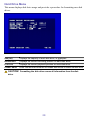
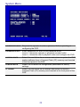
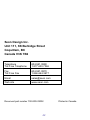
1
Trooper® TR9 Mobile DVR System Installation and User’s Guide *700-0034* Document part number 700-0034 R002 Seon Design® Inc. Seon Design Inc. is a specialist in the design and manufacture of video surveillance systems for mobile applications. Seon has been the preferred solutions provider for the pupil transportation industry since 1999. Today, we are proud that our success in this area has made us the leading manufacturer of mobile video surveillance systems in North America. Contact Information Seon Design Inc. Unit 111, 3B Burbidge Street Coquitlam, BC Canada V3K 7B2 Telephone 604.941.0880 Toll Free Telephone 1.877.630.7366 Fax 604.941.0870 Toll Free Fax 1.866.664.3677 Email [email protected] Web site www.seon.com Seon Design Inc. Trademarks Seon Design Inc. holds the following trademarks: Trooper® is a registered trademark of Seon Design Inc. “Seon Design” is a registered trademark of Seon Design Inc. ) is a registered trademark of Seon Design Inc. The Seon logo ( In this User Manual there are references to trademarks, registered trademarks, and product names not owned by Seon Design Inc. that are the property of their respective owners. They are used in this User Manual for identification purposes only. User Manual Revision This is the March 2008 revision for this User Manual and is copyright, March 2008 of Seon Design Inc. All rights reserved. 2 Exclusion of Liability SEON DESIGN INC.: (a) MAKES NO REPRESENTATION, WARRANTY, GUARANTEE OR COVENANT, EXPRESS OR IMPLIED, AS TO THE ACCURACY, SUFFICIENCY OR SUITABILITY OF ANY TECHNICAL OR OTHER INFORMATION PROVIDED IN THIS USER MANUAL OR ANY OTHER USER OR OTHER MANUAL OR OTHER DOCUMENTATION PROVIDED BY SEON DESIGN INC. WITH RESPECT TO THE PRODUCT(S) DESCRIBED HEREIN, INCLUDING WITHOUT LIMITATION ANY DESCRIPTION OF GOODS OR SERVICES, SPECIFICATIONS, MODELS, DRAWINGS, OR DIAGRAMS. (b) DOES NOT ASSUME AND SHALL NOT BE SUBJECT TO AND DISCLAIMS ANY AND ALL RESPONSIBILITY AND/OR LIABILITY FOR LOSSES, DAMAGES, COSTS OR EXPENSES ARISING OUT OF BREACH OF CONTRACT OR OF WARRANTY, TORT (INCLUDING NEGLIGENCE AND STRICT LIABILITY) OR OTHERWISE, WHETHER SPECIAL, DIRECT, INDIRECT, CONSEQUENTIAL, INCIDENTAL, SPECIAL OR CONTINGENT, WHICH MIGHT ARISE OUT OF THE USE OF SUCH INFORMATION. THE USE OF ANY SUCH INFORMATION WILL BE ENTIRELY AT THE USER’S RISK; AND (c) EXPRESSLY DISCLOSES THAT IF THIS MANUAL IS WRITTEN IN ANY LANGUAGE OTHER THAN ENGLISH, THAT ALTHOUGH SEON DESIGN INC. HAS USED REASONABLE CARE TO MAINTAIN THE ACCURACY OF THE TRANSLATION FROM THE ENGLISH LANGUAGE, THE ACCURACY OF SUCH TRANSLATION IS NOT GUARANTEED OR WARRANTED BY SEON DESIGN INC. PLEASE REFER TO THE ENGLISH LANGUAGE VERSION OF THIS USER MANUAL FOR APPROVED SEON CONTENT. THE ENGLISH LANGUAGE VERSION IS AVAILABLE UPON REQUEST FROM THE SEON CUSTOMER SERVICE DEPARTMENT. PLEASE REFER TO THE SEON DESIGN INC. PRODUCT WARRANTY APPLICABLE TO THE PRODUCT(S) DESCRIBED IN THIS USER MANUAL WHICH EXCLUSIVELY SETS FORTH SEON DESIGN INC.’S ENTIRE LIABILITY ARISING FROM OR IN CONNECTION WITH SUCH PRODUCT(S) AND THEIR USE AND THE EXCLUSIVE REMEDIES AVAILABLE FOR PURCHASERS AND USERS THEREOF. Document Part Number This User Manual is valid for Seon Design Inc. Document Part Number 700-0034. PRINTED IN CANADA 3 Table of Contents Features......................................................................................................5 Unpacking Your TR9 DVR ..........................................................................6 Docking Tray Installation.............................................................................7 Wiring the DVR ...........................................................................................8 Power and Ignition Harness ...................................................................9 Camera Harness ....................................................................................9 Alarm Harness .....................................................................................10 Vehicle Signal Harness ........................................................................10 CAN (SAE-J1939) Signal Harness .......................................................10 Speed Harness ....................................................................................11 GPS Sensor and Harness ....................................................................11 Operating the DVR....................................................................................12 Front Panel Controls ............................................................................12 Detachable Keypad (ordered separately) .............................................14 Video Search........................................................................................16 Smart-Start ...........................................................................................18 Advanced Smart-Temp ........................................................................18 Configuring the DVR .................................................................................19 Password Entry ....................................................................................19 Main Menu ...........................................................................................20 Set Time and Date Menu......................................................................20 Timer Settings Menu ............................................................................21 Camera Titles Menu .............................................................................22 Motion Recording Menu .......................................................................22 Record Menu........................................................................................24 Signal/Speed/GPS Menu......................................................................25 Network Menu ......................................................................................26 Buzzer Menu ........................................................................................27 Hard Drive Menu ..................................................................................28 System Menu .......................................................................................29 Troubleshooting ........................................................................................30 Power Problems...................................................................................30 Video Problems....................................................................................31 Audio Problems....................................................................................31 Maintenance .............................................................................................32 Cleaning the Camera ...........................................................................32 Cleaning the DVR and Docking Tray ....................................................32 Changing the DVR Ventilation Filter .....................................................32 Specifications............................................................................................33 Recording Time ....................................................................................35 SEON DESIGN® INC. PRODUCT WARRANTY .......................................37 Features The Trooper TR9 Mobile DVR System can record and play back audio, video, vehicle data, and GPS information. The TR9 DVR provides the following features: • Extremely rugged design, engineered specifically for mobile use • Nine channels of high-quality video recording (720×484 resolution) • Two channels of high-quality audio recording • Five vehicle signal status inputs, one speed sensor input, one GPS data input • CAN vehicle data interface (SAE-J1939 compliant) • Configurable image quality and recording speed • Alarm event or motion triggered fast recording speed • Extended recording times using “hot-swappable” hard drives up to 320 Gigabytes total capacity (two 160 GB hard drives) • On-screen display of: ▪ Time, date, vehicle identification, and camera name ▪ GPS data, including location and vehicle speed ▪ Five vehicle signal inputs and system voltage • Repeat recording, user selectable on or off • Variable delay-on and delay-off recording, user selectable from 0 to 60 minutes • Thirteen daily/weekly timers to set DVR recording speed and start/stop times • Smart-Start™ power-up protection that prevents potential DVR damage from voltage spikes and drops during vehicle start-up • Advanced Smart-Temp™ controls DVR heating and cooling functions to ensure optimum performance at high and low operating temperatures • Temporary power switch for setup and playback without turning on the vehicle ignition • Front panel audio and video output jacks for setup and playback • Detachable keypad for operating and configuring the DVR • Video playback search functions based on file segment, date/time, or alarm event • Front panel CompactFlash® memory card slot for saving images and video • Ethernet port for remote operation over a Local Area Network or the Internet 5 Unpacking Your TR9 DVR Your TR9 DVR includes the following parts: DVR with one or two (optional) removable disk drives and two disk lock keys (cylindrical keys) Docking tray with two door keys (flat keys), eight mounting screws, one cable grommet, and one hole plug Power and ignition harness with inline fuse holders and butt-splice wire connectors Alarm signal harness, customized to interface with existing silent alarm switches Vehicle signal harness (for brakes, turn signals, stop and warning lights) Camera harness or camera with harness (if purchased) Speed signal harness (if purchased) GPS receiver and harness (if purchased) CAN (SAE-J1939 compliant) signal harness (if purchased) Your TR9 DVR does not include the keypad which must be ordered separately. Detachable keypad and cable If any of the parts are missing or you would like to purchase, please contact your sales representative at Seon Design. 6 Docking Tray Installation The TR9 DVR can be mounted horizontally (on the floor or on a shelf) or vertically upright (against a wall or bulkhead). CAUTION! Do not mount the TR9 DVR in an inverted position. The DVR could fall from the docking tray when the door is opened, injuring the operator and damaging the DVR. 1 2 Use one of the flat keys to unlock the docking tray door. Slide the DVR out of the docking tray. Use a Phillips screwdriver to remove the five machine screws that fasten the termination panel to the docking tray. Remove the termination panel from the docking tray. Docking tray door lock Machine screws (×5) Termination panel Docking tray mounting holes (×4) Docking tray DVR 3 4 5 6 7 Cable grommet Install the cable grommet in the access hole where the wiring harnesses enter the docking tray. Install the hole-plug in the unused access hole. Use the four enclosed #10×¾” metal screws or #10×1” self drilling screws to fasten the docking tray to a sturdy horizontal or vertical surface. Make sure the mounting location allows access to the four machine screws that secure the termination panel to the docking tray. Install the wiring harnesses as described in the Wiring instructions starting on page 8 of this manual. Fasten the termination panel to the docking tray using the five machine screws that were removed in step 2. Slide the DVR into the docking tray. Close and lock the docking tray door. 7 Wiring the DVR All TR9 wiring harnesses plug into connectors on the termination panel of the docking tray. The termination panel must be removed from the docking tray to connect the wiring harnesses. Follow the instructions on page 7 of this manual to remove the termination panel and to install the cable grommet and hole plug in the docking tray access holes. NOTE: Audio input jacks 1 and 2 are connected in parallel with the audio inputs of cameras 1 and 2, respectively. If you connect remote microphones to the audio input jacks, the audio signals from the camera harness must be disconnected inside the camera. See the Camera Harness section of this manual on page 9 for details. The wiring harnesses enter the docking tray through one of the cable access holes. Leave enough slack in the cables to allow the termination panel to be removed with the harnesses attached. The wiring harnesses can be surface mounted or concealed. If a harness is surface mounted, ensure that it is secured at frequent points and protected from sharp corners. If a harness is concealed, pull it from the un-terminated end to minimize the size requirements of conduits and access holes. The standard wiring harness length is 20 feet (6m) long. Please contact Seon Design if you need a longer harness. 8 Power and Ignition Harness 1A inline fuse to ignition switch Butt-splice wire connectors Red: Battery + (thru 10A inline fuse) Black: Battery – Yellow: Ignition Switch (thru 1A inline fuse) NOTE: The power harness must be connected as close to the battery (or the master battery switch) as possible to filter power surges and to avoid a low-voltage DVR shutdown when the battery is heavily loaded. Camera Harness Blue: Video – Yellow: Video + White: Green: Black: Red: Audio – Audio + Power – Power + Circuit board inside camera NOTE: Audio input jacks 1 and 2 on the termination panel are connected in parallel with the audio inputs of cameras 1 and 2, respectively. If you connect remote microphones to the audio input jacks, the audio signals from the camera harness must be disconnected inside the camera. 9 Alarm Harness Black: Alarm switch – Red: Alarm switch + The alarm harness is used to trigger the recording of an alarm event and to increase the recording quality and speed for a configurable time period after the alarm. The recorded alarm event can be used during video playback to quickly search for important incidents. Connect the red wire to the black wire (or to ground) through a normally open alarm switch. Use the vehicle’s silent alarm switch if possible. See the Record Menu on page 24 of this manual for configuration details and Video Search on page 16 for alarm search details. Vehicle Signal Harness Black: Ch.1 - LT (Left Turn Signal) Green: Ch.2 - STP (Stop Arm) Red: Ch.3 - BRK (Brakes) White: Ch.5 - RT (Right Turn Signal) Brown: Ch.4 - WRN (Warning Lights) NOTE: Always connect the vehicle signal inputs to a fuse-protected circuit. Each input can be configured to display the status text when the signal is 12 VDC (active high – default setting) or grounded (active low). The default text shown above for each input can be changed. See the Signal/Speed/GPS Menu on page 25 of this manual for configuring details. CAN (SAE-J1939) Signal Harness The CAN vehicle data interface (SAE-J1939 compliant) provides a connection to the vehicle’s internal CAN data bus. Please contact Seon Design about a custom interface cable for your vehicle. 10 Speed Harness Black: Signal Ground (0 VDC) Green: Speed Pulse Signal Red: Speed Sensor Power (7.5 VDC) All speed signal inputs are protected against short circuits and transients. The speed pulse input is designed to interface to speed sensors that output a pulse signal of up to 20 VDC, 20 VAC peak-to-peak, or to speed sensors that use ‘open-collector’ style outputs. See the Signal/Speed/GPS Menu on page 25 of this manual for speed calibration information. Contact Seon Design for recommended speed sensors to use with the TR9 DVR System. Refer to the documentation that comes with the speed sensor for further information on connecting to an external speed sensor. The TR9 DVR System can also interface directly to some types of transmission control modules (TCM) in vehicles. Please contact Seon Design for details about interfacing to different TCMs. GPS Sensor and Harness Black White Green Red The GPS receiver must be mounted horizontally (parallel to the ground), on the top of the vehicle to obtain a clear ‘line-of-sight’ view of the GPS satellites overhead. The GPS receiver has a built-in magnetic base that holds securely to steel panels. For nonsteel or composite panels, use an outdoor weatherproof silicone to secure the receiver to the top of the vehicle. NOTE: Use an outdoor weatherproof silicone to seal the hole where the GPS cable goes through an exterior panel. 11 Operating the DVR To view live or recorded video on the TR9 DVR: 1 Connect a video monitor to the audio and video output jacks on the front panel of the DVR. 2 Plug the detachable keypad cable into the socket on the front panel of the DVR. 3 Use the front panel controls and the detachable keypad to operate the DVR, as described below. Front Panel Controls CAUTION! The CompactFlash (CF) memory card can only be inserted with the card label facing up. Forcing the CF card into the slot could damage the internal connector. Slowly insert the card until the connector engages — the card should feel snug in the slot. CAUTION! Unlocking and removing a disk drive while it is recording will delete the current video segment. Pressing the STOP button on the keypad or turning the vehicle ignition OFF is the only safe way of correctly creating the video segment. 12 AUDIO OUT and VIDEO OUT jacks Connect a video monitor to these jacks to view live or recorded video, or to configure the DVR. COMPACT FLASH (CF) The DVR can save audio and video information to a removable card slot Compact Flash (CF) memory card. The DVR system software can also be updated from a CF card. Disk drive access light This red light is on when the DVR is reading or writing data on the disk drive. Do not unlock the disk drive while this light is on. Disk drive lock Use a key to unlock the disk drive before attempting to pull the disk drive out of the DVR. Do not unlock the disk drive while the disk drive access light is on. Disk drive power light This green light is on when a disk drive is properly installed and locked. The DVR can only access the disk drive while this light is on. KEYPAD cable socket Plug the keypad cable into this socket to operate or configure the DVR from the keypad. LOW VOLTAGE light This red light turns on steady when the DVR input voltage drops below 10.5 VDC. The DVR will stop recording while this light is on. The light will turn off and recording will resume when the DVR input voltage rises above 10.9 VDC. LOW/HIGH TEMP light This red light will flash if the DVR temperature drops below 5°F (-15°C) or rises above 140°F (60°C). The DVR will stop recording while this light is flashing. Recording will resume when the internal heater and fan bring the DVR temperature within the operating temperature range. TEMP POWER button Press this button for 5 seconds to turn DVR power on or off while the ignition switch is off. Power will automatically turn off if the ignition switch is off and no keypad buttons are pressed for 5 minutes. Press this button for 5 seconds to turn DVR power on and start recording during the delay-on period. Press this button for 5 seconds to turn DVR power off during the delay-off period. T 13 Detachable Keypad (Ordered separately) The TR9 DVR can be controlled and configured from the detachable keypad shown below. CHANNEL (1-9) buttons COPY button DISPLAY ENTER JOG button button wheel While the DVR is in multi-channel display mode, press a CHANNEL button to display a single, full-screen image. While in picture-in-picture (PIP) display mode, press a CHANNEL button to select a full-screen image, and then press a second CHANNEL button to select a PIP image. Press this button to transfer audio and video information to a Compact Flash (CF) memory card. Read the TR-CFR Installation and User’s Guide (document part number 700-0021) for detailed instructions. Press this button to toggle the text overlay information on and off. The text information includes date and time, vehicle and camera titles, signal status, vehicle speed, playback or recording speed, and disk usage. While entering a password, configuring the DVR, or searching for video, press this button to accept a menu or search selection. While the DVR is paused, turn the JOG wheel clockwise to advance one video frame or counter-clockwise to go back one frame. During DVR configuration, use the JOG wheel to quickly change menu values or title characters. MENU button While the DVR is stopped, press this button to start configuring the DVR. During configuration, press this button to go back to a previous menu. From the Main Menu press this button to stop configuring and resume normal DVR operation. MODE button While the DVR is recording, playing or paused, press this button to switch between several multi-channel video display layouts. PAUSE PLAY Press this button to pause video playback and display a still frame. Use the JOG wheel to display the next or previous still frames. button While the DVR is not recording, press this button to playback recorded audio and video. Use the SHUTTLE wheel to control playback speed and direction. light This green light is on when the keypad is plugged into the DVR and DVR power is on. The light flashes off momentarily when a button is pressed. POWER REC button button While the DVR is stopped, press this button to start recording audio and video information. 14 SEARCH button While the DVR is stopped, press this button to display a search menu. You can search the recorded audio and video for a particular video segment, alarm event, or date and time. Use the JOG wheel to select a segment or alarm event, then press the ENTER button to play the selected video. SELECT button Press this button to change the video channel selections in a multichannel video display layout. Press one of the CHANNEL buttons to assign that channel to the currently selected display panel. Press the ENTER button to advance to the next panel without changing the channel. SHUTTLE wheel While the DVR is playing, turn the SHUTTLE wheel clockwise or counterclockwise to increase the forward or reverse playback speed from 2 to 600 times normal speed. The further you turn the SHUTTLE wheel, the faster the playback speed. When you release the SHUTTLE wheel, playback returns to normal speed. STOP button While the DVR is recording, playing or paused, press this button to stop the DVR. If no other buttons are pressed within 10 seconds, the DVR will automatically start recording, if scheduled to do so. During the 10 seconds, press the MENU, SEARCH, PLAY, COPY or RECORD buttons to start an operation. ZOOM button While the DVR is recording, playing or paused in full-screen display mode, press this button to display the image at 200% magnification. Use the JOG wheel to pan left and right, or up and down. Press the ENTER button to toggle the pan direction between left/right and up/down. 15 Video Search The TR9 DVR provides a versatile video search function that quickly locates video clips from a list of video segments, from a list of alarm events, or by date and time. To search for a video clip: 1 2 Press the STOP button to stop recording or playback. Press the SEARCH button to display the Search Menu. To search for a video segment: 1 2 Turn the JOG wheel to select By Segment List from the main Search Menu. Press the ENTER button to display the Segment Search list. 16 3 4 Turn the JOG wheel to select a video segment. Press the ENTER button to play the video segment. To search for an alarm: 1 2 Turn the JOG wheel to select By Alarm List from the main Search Menu. Press the ENTER button to display the Alarm Search list. ALARM SEARCH 0001 0002 0003 0004 0005 0006 0007 0008 0009 0010 3 4 PL PL A1 V1 PL A1 PL A1 V9 PL 2005/09/09 2005/09/09 2005/09/12 2005/09/12 2005/09/13 2005/09/13 2005/09/14 2005/09/14 2005/09/15 2005/09/15 07:35:26 03:05:12 07:31:45 03:02:41 07:36:19 03:06:08 07:38:21 03:03:02 07:32:35 03:05:15 HDD-1 HDD-1 HDD-1 HDD-1 HDD-1 HDD-1 HDD-1 HDD-1 HDD-1 HDD-1 Turn the JOG wheel to select an alarm. The alarm codes are: A1 Indicates an external alarm signal PL Indicates a power loss V1 Indicates the loss of one video signal (V1 to V9 for channels 1 to 9) VA Indicates the loss of all video signals Press the ENTER button to play the selected alarm. To search by date and time: 1 2 Turn the JOG wheel to select By Date Time from the main Search Menu. Press the ENTER button to display the Date Time Search menu. 17 3 4 Turn the JOG wheel to change the value of each entry in the date and time. Press the ENTER button to advance to the next entry. When the date and time have been entered, press the SEARCH button to play the video starting at the selected date and time, or press the MENU button to return to the main Search Menu. Smart-Start The TR9 DVR displays and records the input voltage. This can be a very helpful diagnostic tool if you encounter low voltage problems with vehicle power supplies. If the voltage to the DVR is too low, the quality of the video signal from the camera will be very poor, resulting in a poor recording. In addition to the on-screen voltage display, the TR9 DVR incorporates a low voltage indicator on the front panel of the DVR. If the voltage to the DVR drops below 10.5 VDC for more than 30 seconds, a Power Loss (PL) alarm will be recorded, the red low voltage light will turn on and the DVR will stop recording. When the voltage rises above 10.9 VDC, the red low voltage light will turn off and the DVR will resume normal operation. Advanced Smart-Temp The TR9 DVR incorporates several advanced features not found in any other system on the market. The Advanced Smart-Temp feature is a key example of how Seon Design is leading the way in developing solutions that benefit the customer directly. Most computer disk drives are designed to operate between 40°F and 120°F. In many geographical areas, the temperature drops well below 40°F, and quite often below 32°F. Advanced Smart-Temp controls the DVR heater and fan to maintain a safe operating temperature. If the temperature inside the DVR drops below 40°F (5°C) or rises above 113°F (45°C), Advanced Smart-Temp flashes the red low/high temp light on the front panel of the DVR. If the temperature inside the DVR rises above 140°F (60°C), Advanced Smart-Temp records a Power Loss (PL) alarm, turns off the disk drives, and flashes the red low/high temp light on the front panel of the DVR. The DVR fan continues operating to bring the DVR back to a safe operating temperature below 113°F (45°C). 18 Configuring the DVR To configure the TR9 DVR: 1 2 3 Connect a video monitor to the audio and video output jacks on the front panel of the DVR. Connect the detachable keypad cable to the socket on the front panel of the DVR. Use the detachable keypad to configure the DVR, as described below. CHANNEL (1-9) buttons ENTER JOG button wheel MENU Press the ENTER button to view a selected menu item or to accept the currently selected value and advance to the next value on a screen. Turn the JOG wheel forward or backward to select a menu item or to change a selected value. button While the DVR is stopped, press the MENU button to start configuring the DVR. During configuration, press this button to go back to a previous menu. From the Main Menu, press this button to stop configuring and resume normal DVR operation. light This green light is on when the keypad is plugged into the DVR and DVR power is on. The light flashes off momentarily when a button is pressed. POWER STOP While configuring the motion menu, press one of these buttons to display the motion detection grid for a channel. button While the DVR is recording, playing or paused, press this button to stop the DVR. If no other buttons are pressed within 10 seconds, the DVR will automatically start recording, if scheduled to do so. During the 10 seconds, press the MENU button to display the Main Menu. Password Entry If passwords are enabled on the System Menu (page 28), you must enter a valid Level 3 password to view the Main Menu and configure the DVR. Turn the JOG wheel to change each character of the password. Press the ENTER button to advance to the next character or to submit the password when all six characters have been entered. 19 Main Menu Press the STOP button and then press the MENU button to view the Main Menu. Use the JOG wheel to select a menu item. Press the ENTER button to view the selected menu item. Set Time and Date Menu DATE Day of the week is set automatically after day, month and year are set. AUTO DAYLIGHT SAVING TIME Select YES to automatically adjust the DVR clock for Daylight Saving Time. As of 2007, on the second Sunday in March, the time changes from 02:00 am to 03:00 am Daylight Saving Time. On the first Sunday in November, the time changes from 02:00 am to 01:00 am Standard Time. 20 Timer Settings Menu Timers are used to restrict recording periods while the ignition switch is on. This feature is useful when a bus has a long drive before picking up any passengers. ENABLE TIMERS Enables all timers. If Enable Timers is ON, the DVR will only record while at least one individual timer is on and the ignition switch is on. If Enable Timers is ON but all individual timers are off, the DVR will never record. If Enable Timers is OFF, the DVR will start recording after the delay-on time and stop recording after the delay-off time. WEEK Enables a timer for one day of the week (SUN, MON, TUE, WED, THU, FRI, AND SAT), all days of the week (DLY), weekdays only (WDAY), or weekends only (WEND). T START/STOP TIME Sets the time when the DVR will start and stop recording. The start time overrides the delay-on time, 30 seconds after the ignition switch is turned on. The delay-off time overrides the stop time. SPEED Sets the recording speed in images/second. SET Enables one timer. 21 Camera Titles Menu Enter descriptive text for each recording channel. Motion Recording Menu The DVR recording speed can be changed when motion is detected in one or more video channels. 22 CH Press a CHANNEL button (1-9) to view and edit the motion detection grid for each channel, as shown above. OP Enables motion detection for each channel. SEN Adjusts the motion detection sensitivity from low (1) to high (4) for each channel. DURATION Adjusts the length of time that the recording speed changes for each channel (1-99 seconds). The recording speed is set in the Alarm Record Speed parameter in the Record Menu (see page 24). ENTER JOG button wheel Press the ENTER button to move from cell to cell in the motion detection grid. Turn the JOG wheel to toggle each motion detection grid cell on () or off ( ). Motion will only be detected in cells that are on. MENU button Press the MENU button to return to the Motion menu. MODE button Press the MODE button to toggle all motion detection grid cells on () or off ( ). 23 Record Menu RECORD SPEED Adjusts the normal recording speed (0.2 to 60 images/second). IMAGE QUALITY Adjusts the recorded image quality/compression from standard quality/highest compression (1) to highest quality/lowest compression (6). REPEAT RECORD Overwrites the oldest video data when both disk drives are full. Disable to stop recording when both disk drives are full. RECORD AUDIO 1 &2 Enables audio recording for each audio input channel DELAY-ON TIME Adjusts the delay from the time the ignition switch is turned on until the DVR turns on (0 seconds to 60 minutes). Delay-on time can be used to ensure the DVR input voltage has time to stabilize or to delay the start of recording until the first passenger is picked up. DELAY-OFF TIME Adjusts the delay from the time the ignition switch is turned off until the DVR turns off (0 seconds to 60 minutes). ALARM RECORDING Changes the recording speed when an alarm event occurs. Alarm events can be triggered by an alarm switch or by video motion detection. ALARM RECORD SPEED Adjusts the recording speed during an alarm event triggered by an alarm switch (0.2 to 60 images/second) ALARM DURATION Adjusts the duration of an alarm event (5 seconds to non-stop) PRE-ALARM RECORDING The DVR maintains a cyclical buffer of 300 images, recorded at the alarm speed and quality. If this option is on, the 300 images preceding an alarm event are recorded. In the case of a Power Loss (PL) alarm, the images are always recorded, even if this option is off. 24 Signal/Speed/GPS Menu SIGNAL Enter descriptive text for each input signal. ACTIVATION Active High displays signal text on the video image when the input signal is 12 VDC. Active Low displays signal text when the signal is grounded. GPS DISPLAY Displays the GPS location and speed on the video image. SPEED PULSE COUNT Enter the number of pulses the speed sensor generates when the vehicle travels on mile. This value can be entered manually or measured by the Calibrate Speed procedure. CALIBRATE SPEED Enter Yes to start the speed calibration procedure. Follow the onscreen instructions to measure the number of pulses the speed sensor generates when the vehicle travels one mile or one kilometer. 25 Network Menu The Ethernet port of the TR9 DVR can be connected to a computer network or to the Internet. With the proper authorization, the TR9 DVR can be operated from a Web browser on any computer on the network or from any computer with Internet access to the network. Please contact Seon Design for network connection and operation information. IP ADDRESS Enter a static IP address for the TR9 DVR. Make sure this address is not used by any other device on your network. If you have a DHCP server on your network, make sure the TR9 IP address is not in the IP address range assigned by the DHCP server. NETMASK Enter the subnet mask for your network (usually 255.255.255.000). GATEWAY Enter the IP address of a router or gateway on your LAN. MAC ADDRESS Do not change the default MAC address unless required by your Internet service provider or network administrator. USERNAMES/ PASSWORDS Enter a username and password for each of the three access levels. Guest User: Can only view live video General User: Can view live video and playback recorded video Administrator: Can control all DVR parameters over the network, including password settings, recording settings, etc. HTTP PORT CTRL PORT DATA PORT Do not change the default port numbers unless they are blocked by your firewall. T 26 Buzzer Menu The TR9 DVR has a built-in buzzer that can be activated under certain warning or alarm conditions. BUZZER ENABLE Enables the following six events to sound the buzzer. NOTE: The operator must press any button on the keypad to turn the buzzer off. Do not enable the buzzer if the operator does not have access to the keypad. RECORD-IN Sounds the buzzer when recording starts. ALARM-IN Sounds the buzzer when the alarm input switch is closed. DISK FULL Sounds the buzzer when both disk drives are full and Repeat Record is off. See the Record Menu on page 24. VIDEO LOSS Sounds the buzzer when any video input signal is disconnected while the DVR is operating. TIMER Sounds the buzzer when a recording timer starts. 27 Hard Drive Menu This menu displays disk drive usage and provides a procedure for formatting new disk drives. SIZE (GB) Displays the capacity of each disk drive, in gigabytes. RECORD POS Displays the current recording position on each disk drive. PLAY POS Displays the current playback position on each disk drive. FORMAT DRIVE Enter Yes and then follow the on-screen instructions to format the disk drive. CAUTION! Formatting the disk drive erases all information from the disk drive. 28 System Menu PASSWORD ENABLE Requires the operator to enter a password before operating or configuring the DVR. PASSWORD LEVELS Enter a password for each of the password levels. Level 2: Allows the operator to playback recorded video. Level 3: Allows the user to playback video and configure the DVR. SYSTEM UPDATE Select Yes and follow the on-screen instructions to update the DVR system software from a Compact Flash (CF) memory card inserted in the front panel of the DVR. LOAD DEFAULTS Select Yes to restore all configuration parameters to factory settings. CF FORMAT Select Yes and follow the on-screen instructions to format a Compact Flash (CF) memory card inserted in the front panel of the DVR. T 29 Troubleshooting Power Problems If the DVR does not turn on 30 seconds after you turn the ignition switch on: • Does the DVR turn on if you press the TEMP POWER button for 5 seconds? See related troubleshooting procedures below if it does not turn on. • Is the yellow wire from the power and ignition harness connected to the ignition switch? • Is the 1A inline fuse blown? If it is blown, determine why it blew before replacing it. If the DVR does not turn on when you press the TEMP POWER button for 5 seconds: • Is the 10A inline fuse blown? If it is blown, determine why it blew before replacing it. • Is the power and ignition harness plugged into the DVR termination panel securely? • Is the power harness from the DVR connected as close to the battery (or master battery switch) as possible? See the Power and Ignition Harness wiring instructions on page 9. • Is the red LOW VOLTAGE light on the front panel of the DVR on steady? Measure the input voltage and determine why it is below 10.5 VDC. • Is the red LOW/HIGH TEMP light on the front panel of the DVR flashing? Wait for the DVR heater and fan to bring the internal temperature of the DVR back to a normal operating temperature of 40°F to 113°F (5°C to 45°C). If the DVR turns on but does not start recording: • Did you wait until the end of the delay-on time to see if recording starts? See the Record Menu configuration instructions on page 24 to determine the delay-on time. • Are the green disk drive power lights on? Make sure the disk drives are properly inserted and locked. • Are the recording timers enabled? If they are enabled, the DVR will not start recording until the current time is within one of the enabled timer periods. See the Timer Settings Menu instructions on page 21. • Is the red LOW/HIGH TEMP light on the front panel of the DVR flashing? Wait for the DVR heater and fan to bring the internal temperature of the DVR back to a normal operating temperature of 40°F to 113°F (5°C to 45°C). • Is the red LOW VOLTAGE light on the front panel of the DVR on steady? Measure the input voltage and determine why it is below 10.5 VDC. 30 Video Problems If there is no video signal from the VIDEO OUTPUT jack on the DVR front panel: • Is a video monitor connected to the VIDEO OUTPUT jack on the termination panel at the back of the DVR? Only one monitor can be connected at a time. If all live camera pictures are snowy, fuzzy or grainy: • Is the red LOW VOLTAGE light on the front panel of the DVR on steady? Measure the input voltage and determine why it is below 10.5 VDC. • Is the power and ignition harness from the DVR connected as close to the battery (or master battery switch) as possible? See the Power and Ignition Harness wiring instructions on page 9. If only one live camera pictures is snowy, fuzzy or grainy: • Are the camera harness connections inside the camera secure? • Is the camera harness damaged? • Is the camera harness plugged into the DVR termination panel securely? Audio Problems If there is no live audio from the AUDIO OUTPUT jacks on the DVR front panel: • Is a video monitor connected to the audio output jacks on the termination panel at the back of the DVR? Only one monitor can be connected at a time. • Is the sensitivity adjustment on the audio module in the camera turned down too low? • Is the camera harness wired to the proper terminal blocks inside the camera? • Is the camera harness damaged? • Is the camera harness plugged into the CAMERA 1 or CAMERA 2 connectors on the DVR termination panel? • If microphones are plugged into the AUDIO INPUT 1 or AUDIO INPUT 2 jacks on the DVR termination panel, are the audio inputs from CAMERA 1 and CAMERA 2 disconnected inside the cameras? 31 Maintenance Cleaning the Camera The camera has a powder-painted stainless steel enclosure. Use a damp cloth with a mild detergent to clean the camera enclosure. The camera window is made from hard-coated, scratch resistant polycarbonate. To make sure the camera window does not get scratched, use a soft, clean, damp cloth with a mild detergent to clean the window. Cleaning the DVR and Docking Tray The DVR enclosure and docking tray are made from 18-gauge steel, coated with an outdoor powder paint. Use a damp cloth with a mild detergent to clean the DVR and docking tray. Do not let any water into the ventilation holes on the DVR enclosure or into the termination panel of the docking tray. Changing the DVR Ventilation Filter Depending on the operating environment, the ventilation filter on the side of the DVR enclosure may need to be changed occasionally. The filter should be cleaned monthly and replaced if it restricts airflow. Failure to replace a blocked ventilation filter will result in the DVR overheating and shutting down on a hot day. To clean or replace the ventilation filter, use a small Phillips screwdriver to remove the filter cover and the filter. Put a clean filter into the filter holder and replace the filter cover and screws. 32 Specifications • Recording: Channels Video resolution Video compression Video quality Recording timers 9 video, 2 audio 720×484 (record and playback) M-JPEG Adjustable, 6 levels 13 configurable recording timers • Playback: Controls Detachable keypad, on-screen display Video display 1 (2× zoom), 2 (PIP), 4, 6, 7, 8 or 9 channels modes 1 Playback speed /32 to 600× Video search Search by video segment, alarm event or time/date • Input signals: Harness length Transient protection Panic alarm Vehicle signals Smart-Speed input GPS 20 feet (6 m) standard, optional special order lengths 600W, each signal input Push-button alarm switch and harness 5 inputs (brakes, turn signals, stop light, warning light) configurable 12 VDC active-high or 0 VDC active-low Built-in speed conditioner, 0-20 VDC, 0-20 VAC peak-to-peak, or open-collector; requires optional speed harness Vehicle location and speed; requires optional GPS receiver and harness CAN vehicle data interface (SAE-J1939 compliant) Vehicle data interface Network RJ-45 Ethernet connector, TCP/IP communication protocol interface 33 • Video storage: Storage medium Storage capacity Automatic overwrite Removable memory Dual hot-swappable 2.5” ruggedized IDE disk drives 160 GB, 240 GB, 320 GB Selectable On or Off Type I or Type II CompactFlash memory card • Power requirements: Input voltage 11 to 18 VDC (optional 36 VDC) Transient 1.5 kW Tranzorbs on power and ignition lines, Smart-Start start-up protection voltage protection • Operating conditions: Operating 40°F to 122°F (5°C to 50°C), built-in heater and fan temperature Operating 0 – 90% RH, non-condensing humidity • DVR material, dimensions and weight: Enclosure Formed 18 gauge steel, outdoor powder paint coating material Dimensions 12.0×5.0×13.1 in. (315×127×427 mm) (W×H×D) Weight 17 lb. (7.7 kg) excluding docking station • Docking station material, dimensions and weight: Enclosure Formed 18 gauge steel, outdoor powder paint coating material Dimensions 12.4×5.0×16.8 in. (315×127×427 mm) (W×H×D) Weight 8 lb. (3.6 kg) with DVR removed 34 Recording Time The recording time of the TR9 DVR depends on: • Disk drive capacity • Recording speed • Image quality/compression setting • Image content, motion and lighting When more than one camera is connected to the TR9 DVR, the recording speed (IPS) for each camera is calculated by dividing the selected recording speed by the number of cameras. For example, for a recording speed of 60 images per second and three cameras, each camera will record 20 images per second. NOTE: The recording times shown below are based on typical image content, motion and lighting conditions. Your recording times may vary. Estimated Recording Time in Hours with 160 GB Disk Capacity (2×80 GB) Image Quality/Compression Setting Images per second (IPS) 1 2 3 4 5 6 60 48 36 28 24 20 18 30 96 72 56 48 40 36 20 144 108 84 72 60 54 15 192 144 112 96 80 72 10 288 216 168 144 120 108 5 576 432 336 288 240 216 1 2,888 2,160 1,680 1,440 1,200 1,080 0.5 5,760 4,320 3,360 2,880 2,400 2,160 0.3 9,600 7,200 5,600 4,800 4,000 3,600 0.2 14,400 10,800 8,400 7,200 6,000 5,400 0.1 28,800 21,600 16,800 14,400 12,000 10,800 35 Estimated Recording Time in Hours with 240 GB Disk Capacity (2×120 GB) Image Quality/Compression Setting Images per second (IPS)) 1 2 3 4 5 6 60 72 54 42 36 30 27 30 144 108 84 72 60 54 20 216 162 126 108 90 81 15 288 216 168 144 120 108 10 432 324 252 216 180 162 5 864 648 504 432 360 324 1 4,320 3,240 2,520 2,160 1,800 1,620 0.5 8,640 6,480 5,040 4,320 3,600 3,240 0.3 14,386 10,790 8,392 7,193 5,994 5,395 0.2 21,600 16,200 12,600 10,800 9,000 8,100 0.1 43,200 32,400 25,200 21,600 18,000 16,200 Estimated Recording Time in Hours with 320 GB Disk Capacity (2×160 GB) Image Quality/Compression Setting Images per second (IPS) 1 2 3 4 5 6 60 96 72 56 48 40 36 30 192 144 112 96 80 72 20 288 216 168 144 120 108 15 384 288 224 192 160 144 10 576 432 336 288 240 216 5 1,152 864 672 576 480 342 1 5,760 4,320 3,360 2,880 2,400 2,160 0.5 11,520 8,640 6,720 5,760 4,800 4,320 0.3 19,200 14,400 11,200 9,600 8,000 7,200 0.2 28,800 21,600 16,800 14,400 12,000 10,800 0.1 57,600 43,200 33,600 28,800 24,000 21,600 36 SEON DESIGN® INC. PRODUCT WARRANTY Seon Design Inc. (Seon) warrants the cameras and components listed below against defects in workmanship and materials provided that such defects appear or are discovered within the respective periods specified below and provided further that the purchaser of such products notifies Seon of such defects within thirty (30) days of the appearance or discovery of such defects: • Five (5) years from date of purchase parts and labor on the SA Wedge Camera Series • One (1) year from date of purchase parts and labor on the SA-IR Illuminator • One (1) year from date of purchase parts and labor on the Trooper Mobile DVR Systems • One (1) year from date of purchase parts and labor on all other products and accessories All service/replacement parts and repairs are warranted for a period of 90 days. Subject to the terms and conditions listed below, during the relevant warranty period, Seon will repair, replace, or refund the purchase price for the defective product, whichever Seon considers to be appropriate in the circumstances, in Seon’s sole and arbitrary opinion, free of charge, any defective products returned prepaid. In the event purchaser has a problem with any Seon product, please call and request a RETURN AUTHORIZATION (RA) NUMBER from the Service Department. Please call 877-630-7366 or (604) 941-0880 and ask for the Service Department. Be sure to have the model number, serial number and the nature of the problem available for the customer service representative. Prior authorization MUST be obtained for all returns, exchanges, or credits. ITEMS SHIPPED TO SEON WITHOUT A CLEARLY IDENTIFIED RA NUMBER MAY BE REFUSED. PRODUCTS RETURNED WILL BE TESTED TO VERIFY THE DEFECT. UPON VERIFICATION OF THE DEFECT, THE PRODUCT WILL BE REPAIRED OR EXCHANGED, OR THE PURCHASE PRICE WILL BE REFUNDED OR CREDITED TO THE CUSTOMER’S ACCOUNT, AT THE 37 SOLE OPTION OF SEON. IN THE EVENT OF REPLACEMENT, THE RETURNED PRODUCT WILL BE CREDITED TO THE CUSTOMER’S ACCOUNT AND A NEW INVOICE ISSUED FOR THE REPLACEMENT ITEM. SEON RESERVES THE RIGHT TO REFUND THE PURCHASE PRICE OR TO ISSUE A CREDIT ONLY IN LIEU OF REPLACEMENT. SEON MAY USE NEW OR REFURBISHED REPLACEMENT PARTS FOR REPAIRING ITS PRODUCTS, AT ITS SOLE AND ARBITRARY DISCRETION. SEON MAY REPLACE AN ENTIRE UNIT WITH AN EQUIVALENT MODEL, AT ITS SOLE AND ARBITRARY DISCRETION. IF A UNIT IS EXCHANGED, THE RETURNED PRODUCT SHALL BECOME THE PROPERTY OF SEON AND THE EXCHANGE PRODUCT BECOMES THE PROPERTY OF THE PURCHASER, AND THE REMAINDER OF THE WARRANTY THAT APPLIED TO THE ORIGINAL UNIT PURCHASED SHALL APPLY TO THE EXCHANGED PRODUCT. EXCHANGE UNITS MAY BE NEW UNITS OR UNITS THAT HAVE BEEN REPAIRED TO FULL FACTORY SPECIFICATIONS AT SEON’S DISCRETION. IF THE PRODUCT IS FOUND TO BE IN GOOD WORKING ORDER OR ITS INABILITY TO FUNCTION PROPERLY IS NOT COVERED BY THIS WARRANTY, THE PRODUCT WILL BE RETURNED IN THE SAME CONDITION AS RECEIVED UNLESS REPAIR IS POSSIBLE AND REQUESTED BY THE CUSTOMER. REPAIRS OF SUCH NATURE WILL INCUR A CHARGE FOR PARTS AND LABOR AND WILL PROCEED ONLY BY AGREEMENT WITH THE CUSTOMER TO ACCEPT THE CHARGE. THIS WARRANTY SHALL NOT APPLY: (a) TO EQUIPMENT NOT SUPPLIED BY SEON; (b) TO EQUIPMENT, INCLUDING, ANY COMPONENTS, WHICH SHALL HAVE BEEN OPERATED IN EXCESS OF RATED CAPACITY, SUBJECT TO NEGLIGENCE, ACCIDENT, OR DAMAGE BY CIRCUMSTANCES BEYOND SEON’S CONTROL, OR TO IMPROPER INSTALLATION, OPERATION, MAINTENANCE, SERVICING, ALTERATIONS OR STORAGE, MODIFICATION WITHOUT SEON’S WRITTEN AUTHORIZATION, MISUSE, VANDALISM, FIRE, FLOODS OR ACTS OF NATURE SO AS, IN SEON’S EXCLUSIVE AND ARBITRARY JUDGMENT, TO AFFECT THE SAME ADVERSELY; OR (c) IF THE SERIAL NUMBER FOR THE PRODUCT HAS BEEN ALTERED IN ANY WAY. (d) IF THE PRODUCT HAS BEEN OPERATED OUTSIDE OF THE SPECIFIED OPERATING ENVIRONMENT SPECIFIED IN THE SEON USERS MANUAL FOR SUCH PRODUCT. 38 DISCLAIMER THIS WARRANTY IS EXCLUSIVE AND IN LIEU OF ALL OTHER REPRESENTATIONS, WARRANTIES, GUARANTEES AND CONDITIONS, EXPRESS OR IMPLIED, STATUTORY OR OTHERWISE AND WITHOUT LIMITING THE GENERALITY OF THE FOREGOING, SEON EXPRESSLY DISCLAIMS AND EXCLUDES ANY IMPLIED WARRANTY OF MERCHANTABILITY, DURABILITY OR FITNESS FOR PURPOSE AND ANY WARRANTIES OR MODIFIED WARRANTIES ARISING FROM USAGE OF TRADE OR COURSE OF DEALING. Any description of the goods or services, whether in writing or made orally by Seon or Seon’s agents, specifications, samples, models, bulletins, drawings, diagrams, engineering sheets or similar materials used in connection with customer’s order are for the sole purpose of identifying the goods and/or services and shall not be construed as an express warranty. Any suggestions by Seon or Seon’s agents regarding use, applications or suitability of the goods and/or services shall not be construed as an express warranty unless confirmed to be such in writing by Seon. Purchaser assumes full responsibility for selecting products to achieve purchaser’s intended purposes, for properly installing and using those products, and for verifying the results obtained therefrom. PURCHASER’S EXCLUSIVE REMEDY AND SEON’S ENTIRE LIABILITY ARISING FROM OR IN CONNECTION WITH PURCHASER’S USE OF THE PRODUCTS AND/OR THIS AGREEMENT SHALL BE REPAIR OR REPLACEMENT OF DEFECTIVE PRODUCTS, OR REFUND OR CREDIT OF THE PURCHASE PRICE OF THE PRODUCTS AS SET FORTH ABOVE. SEON SHALL NOT BE SUBJECT TO AND DISCLAIMS: (A) ANY OTHER OBLIGATIONS OR LIABILITIES ARISING OUT OF BREACH OF CONTRACT OR OF WARRANTY, (B) ANY OBLIGATIONS WHATSOEVER ARISING FROM TORT CLAIMS (INCLUDING NEGLIGENCE, AND STRICT LIABILITY) OR ARISING UNDER OTHER THEORIES OF LAW WITH RESPECT TO GOODS SOLD OR SERVICES RENDERED BY SEON, OR ANY UNDERTAKINGS, ACTS OR OMISSIONS RELATING THERETO, AND (C) ALL CONSEQUENTIAL, INCIDENTAL, SPECIAL AND CONTINGENT DAMAGES WHATSOEVER, EVEN IF SEON HAS BEEN SPECIFICALLY ADVISED OF THE POSSIBILITY OF SUCH DAMAGES. Without limiting the generality of the foregoing, Seon specifically disclaims any liability for property or personal injury damages, penalties, special or punitive damages, damages for lost profits or revenues, loss of use of goods or any associated equipment, cost of capital, cost of substitute goods, facilities or services, down-time, shutdown or slow-down costs, or for any other types of economic loss, and for claims of customer’s customers or any third party for any such damages. Some jurisdictions do not allow limitation or exclusion of incidental or consequential damages, so this limitation or exclusion 39 may not apply to purchaser. In no event shall Seon’s total liability for any damages to purchaser or any other person in connection with the products or this agreement exceed the lower of the suggested list price or the actual price paid for the products, regardless of whether such liability arises from contract, tort, warranty or any other form of claim. If any provision of this agreement is found to be void, invalid, or unenforceable, that finding shall not affect the remaining provisions, all of which shall be enforced to the full extent permitted by law. If any remedy hereunder is determined to have failed of its essential purpose, the limitations of liability and exclusion of damages set forth above shall remain in full force and effect. This agreement may be modified only in writing signed by a duly authorized representative of Seon. Provisions Applicable to American Customers For those customers whose mailing address is in the United States, Seon’s offer and any agreement of sale resulting therefrom shall be governed by and construed in accordance with the internal and domestic laws of the State of WASHINGTON without giving effect to the conflict of laws rules thereof. The Superior Court of Washington for Whatcom County and U.S. District Court for the Western District of Washington (“the U.S. Closed Courts”) shall have exclusive jurisdiction to entertain and determine all disputes and claims, whether for specific performance, injunction, declaration or otherwise arising out of or in any way connected with the construction, breach, or alleged, threatened or anticipated breach of the contract resulting from this offer and shall have jurisdiction to hear and determine all questions as to the validity, existence or enforceability thereof. Customer specifically consents to such Court’s exercise of jurisdiction over it. The purchaser attorns to the exclusive jurisdictions of the jurisdiction of the U.S. Closed Courts, waives any obligation to venue in any action or proceeding regarding Seon Products and waives any objection that the U.S. Closed Courts are an inconvenient forum or do not have jurisdiction over the purchaser of Seon. The United Nations Convention On Contracts For The International Sale Of Goods shall not apply. 40 Provisions Applicable to Canadian Customers For those customers whose mailing address is in Canada, Seon’s offer and any agreement of sale resulting therefrom shall be governed by and construed in accordance with the internal and domestic laws of the Province of BRITISH COLUMBIA and the laws of Canada applicable therein without giving effect to the conflict of laws rules thereof. The courts of British Columbia (the “Canadian Closed Courts”) shall have exclusive jurisdiction to entertain and determine all disputes and claims, whether for specific performance, injunction, declaration or otherwise arising out of or in any way connected with the construction, breach, or alleged, threatened or anticipated breach of the contract resulting from this offer and shall have jurisdiction to hear and determine all questions as to the validity, existence or enforceability thereof. The purchaser attorns to the exclusive jurisdictions of the jurisdiction of the Canadian Closed Courts, waives any obligation to venue in any action or proceeding regarding Seon Products and waives any objection that the Canadian Closed Courts are an inconvenient forum or do not have jurisdiction over the purchaser of Seon. The United Nations Convention On Contracts For The International Sale Of Goods shall not apply. 41 Seon Design Inc. Unit 111, 3B Burbidge Street Coquitlam, BC Canada V3K 7B2 Telephone Toll Free Telephone 604.941.0880 1.877.630.7366 Fax Toll Free Fax 604.941.0870 1.866.664.3677 Email [email protected] Web site www.seon.com Document part number 700-0034 R002 42 Printed in Canada