1
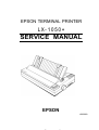
EPSON TERMINAL PRINTER
LX-1050+
SERVICE MANUAL
EPSON
4003283
,’
,,
NOTICE
All rights reserved. Reproduction of any part of this manual in any form whatsoever without
SEIKO EPSON’s express written permission is forbidden.
The contents of this manual are subjects to change without notice.
All efforts have been made to ensure theaccuracyof the contents of this manuaI. However, should
any errors be detected, SEIKO EPSON would greatly appreciate being informed of them.
The above notwithstanding SEIKO EPSON can assume no responsibility for any errors in this
manual or the consequence thereof.
Epson and Epson ESC/P are registered trademark of Seiko Epson Corporation.
General Notice: Other product names used herein are for identication purposes only and maybe
trademarks of their respective campanies.
@ Copyright 1994 by SEIKO EPSON CORPORATION Nagano, Japan
-i-
PRECAUTIONS
Precautionary notations throughout the text are categorized relative to 1) personal inju~ and 2)
damage to equipment.
DANGER Signals a precaution which, if ignored, could result in serious or fatal personal injury.
Great caution should be exercised in performing procedures preceded by DANGER
Headings.
WARNING Signals a precaution which, if ignored, could result in damage to equipment.
The precautionary measures itemized below should always be observed when performing repair/
maintenance procedures.
DANGER
1.
ALWAYS DISCONNECT THE PRODUCT FROM BOTH THE POWER SOURCE AND
PERIPHERAL DEVICES PERFORMING ANY MAINTENANCE OR REPAIR PROCEDURE.
2.
NO WORK SHOULD BE PERFORMED ON THE UNIT BY PERSONS UNFAMILIAR WITH
BASIC SAFETY MEASURES AS DICTATED FOR ALL ELECTRONICS TECHNICIANS IN
THEIR LINE OF WORK.
3.
WHEN PERFORMING TESTING AS DICTATED WITHIN THIS MANUAL, DO NOT
CONNECT THE UNIT TO A POWER SOURCE UNTIL INSTRUCTED TO DO SO. WHEN
THE POWER SUPPLY CABLE MUST BE CONNECTED, USE EXTREME CAUTION IN
WORKING ON POWER SUPPLY AND OTHER ELECTRONIC COMPONENTS.
WARNING
1.
REPAIRS ON EPSON PRODUCT SHOULD BE PERFORMED ONLY BY AN EPSON
CERTIFIED REPAIR TECHNICIAN.
2.
MAKE CERTAIN THAT THE SOURCE VOLTAGE IS THE SAME AS THE RATED VOLTAGE, LISTED ON THE SERIAL NUMBER/RATING PLATE. IF THE EPSON PRODUCT
HAS A PRIMARY AC RATING DIFFERENT FROM AVAILABLE POWER SOURCE, DO
NOT CONNECT IT TO THE POWER SOURCE.
3.
ALWAYS VERIFY THAT THE EPSON PRODUCT HAS BEEN DISCONNECTED FROM
THE POWER SOURCE BEFORE REMOVING OR REPLACING PRINTED CIRCUIT
BOARDS AND/OR INDIVIDUAL CHIPS.
4.
IN ORDER TO PROTECT SENSITIVE MICROPROCESSORS AND CIRCUITRY, USE
STATIC DISCHARGE EQUIPMENT, SUCH AS ANTI-STATIC WRIST STRAPS, WHEN
ACCESSING INTERNAL COMPONENTS.
5.
REPLACE MALFUNCTIONING COMPONENTS ONLY WITH THOSE COMPONENTS
BY THE MANUFACTURE; INTRODUCTION OF SECOND-SOURCE ICS OR OTHER
NONAPPROVED COMPONENTS MAY DAMAGE THE PRODUCT AND VOID ANY
APPLICABLE EPSON WARRANTY.
- ii -
PREFACE
This manual describes functions, theory of electrical and mechanical operations, maintenance, and repair
of LX-105O+.
The instructions and procedures included herein are intended for the experience repair technician, and
attention should be given to the precautions on the preceding page. The chapters are organized as
follows:
CHAPTER 1. GENERAL DESCRIPTION
Provides a general product overview, lists specifications, and illustrates the main components of the printer.
CHAPTER 2. OPERATING PRINCIPLES
Describes the theory of printer operation.
CHAPTER 3. DISASSEMBLY AND ASSEMBLY
Includes a step-by-step guide for product disassembly and assembly.
CHAPTER 4. ADJUSTMENTS
Includes a step-by-step guide for adjustment.
CHAPTER 5. TROUBLESHOOTING
Provides Epson-approved techniques for adjustment.
CHAPTER 6. MAINTENANCE
Describes preventive maintenance techniques and lists lubricants and adhesives required to service the equipment.
APPENDIX
Describes connector pin assignments, circuit diagrams, circuit board component layout and exploded diagram.
The contents of this manual are subject to change without notice.
- iv -
REVISION SHEET
Revision
Issue Date
Revision Page
Rev. A
May 18, 1994
1st issue
-v-
TABLE OF CONTENTS
CHAPTER 1.
CHAPTER 2.
CHAPTER 3.
CHAPTER 4.
CHAPTER 5.
CHAPTER 6.
APPENDIX
GENERAL DESCRIPTION
OPERATING PRINCIPLES
DISASSEMBLY AND ASSEMBLY
ADJUSTMENTS
TROUBLESHOOTING
MAINTENANCE
- vi -
Chapter 1
General Description
Table of Contents
1.1 FEATURES
1-1
1.2 SPECIFICATIONS
1.2.1 Printing Specifications. . . . . . . . . . . . . . . . . . . . . . . . . . . . . . . . . . . . . . .
1.2.2 Paper Handling Specification. . . . . . . . . . . . . . . . . . . . . . . . . . . . . . . . . .
1.2.3 Paper Specification . . . . . . . . . . . . . . . . . . . . . . . . . . . . . . . . . . . . . . . . .
1.2.4 Ink Ribbon . . . . . . . . . . . . . . . . . . . . . . . . . . . . . . . . . . . . . . . . . . . . . . . .
1.2.5 Environmental Conditions . . . . . . . . . . . . . . . . . . . . . . . . . . . . . . . . . . . .
1.2.6 Electrical Specifications. . . . . . . . . . . . . . . . . . . . . . . . . . . . . . . . . . . . . .
1.2.7 Reliability. . . . . . . . . . . . . . . . . . . . . . . . . . . . . . . . . . . . . . . . . . . . . . . . .
1.2.8 Safety Approval. . . . . . . . . . . . . . . . . . . . . . . . . . . . . . . . . . . . . . . . . . . .
1.2.9 Physical Specifications . . . . . . . . . . . . . . . . . . . . . . . . . . . . . . . . . . . . . .
1-3
1-3
1-5
1-5
1-7
1-7
1-7
1-7
1-7
1-7
1.3 INTERFACE OVERVIEW
1-8
1.3.1 Parallel Interface. . . . . . . . . . . . . . . . . . . . . . . . . . . . . . . . . . . . . . . . . . . 1-8
1.3.2 Optional Interface #8143. . . . . . . . . . . . . . . . . . . . . . . . . . . . . . . . . . . . . 1-9
1-1o
1.4 PRINTER OPERATIONS
1.4.1 Control Panel. . . . . . . . . . . . . . . . . . . . . . . . . . . . . . . . . . . . . . . . . . . . . 1-10
1.4.2 SelecType Functions. . . . . . . . . . . . . . . . . . . . . . . . . . . . . . . . . . . . . . . 1-11
1.4.3 MicroAdjustment. . . . . . . . . . . . . . . . . . . . . . . . . . . . . . . . . . . . . . . . . . 1-11
1.4.4 Panel Operational Power ON....... . . . . . . . . . . . . . . . . . . . . . . . . . 1-11
1.4.5 DIP Switch Settings. . . . . . . . . . . . . . . . . . . . . . . . . . . . . . . . . . . . . . . . 1-12
1.4.6 Buzzer Operation. . . . . . . . . . . . . . . . . . . . . . . . . . . . . . . . . . . . . . . . . . 1-14
1.4.7 EEPROM Reset. . . . . . . . . . . . . . . . . . . . . . . . . . . . . . . . . . . . . . . . . . . 1-14
1.5 MAIN COMPONENTS
1.5.1 TAMA Main Control Board. . . . . . . . . . . . . . . . . . . . . . . . . . . . . . . . . . .
1.5.2 TAa Filter Unit... . . . . . . . . . . . . . . . . . . . . . . . . . . . . . . . . . . . . . . . . .
1.5.3 Printer Mechanism (M-3D60). . . . . . . . . . . . . . . . . . . . . . . . . . . . . . . . .
1-15
1-15
1-16
1-16
List of Figures
Figure 1-1. Exterior View of the LX-105O+. . . . . . . . . . . . . . . . . . . . . . . . . . . . . 1-1
Figure l-2. Pin Configuration. . . . . . . . . . . . . . . . . . . . . . . . . . . . . . . . . . . . . . . 1-2
Figure 1-3. Printable Area - Cut Sheet . . . . . . . . . . . . . . . . . . . . . . . . . . . . . . . 1-5
Figure l-4. PrintableArea -Continuous Paper. . . . . . . . . . . . . . . . . . . . . . . . . 1-6
Figure l-5. Adjust Lever Position. . . . . . . . . . . . . . . . . . . . . . . . . . . . . . . . . . . . 1-6
Figure l-6. Data Transmission Timing . . . . . . . . . . . . . . . . . . . . . . . . . . . . . . . . 1-8
Figure l-7. Control Panel. . . . . . . . . . . . . . . . . . . . . . . . . . . . . . . . . . . . . . . . . 1-10
Figure l-8. TAMA Board Component Layout . . . . . . . . . . . . . . . . . . . . . . . . . 1-15
Figure 1-9. TAa Filter Unit. . . . . . . . . . . . . . . . . . . . . . . . . . . . . . . . . . . . . . . . 1-16
Figure 1-11. Printer Mechanism (M-3D60) . . . . . . . . . . . . . . . . . . . . . . . . . . . 1-16
List of Tables
Table
1-1.
Options
for LX-105O+ . . . . . . . . . . . . . . . . . . . . . . . . . . . . . . . . . . . . 1-1
Table 1-2. Print Speed and Printable Columns . . . . . . . . . . . . . . . . . . . . . . . . . l-s
Table
Table
Table
Table
Table
Table
Table
Table
l-3.
CharacterTables. . . . . . . . . . . . . . . . . . . . . . . . . . . . . . . . . . . . . . . . I-A
-4. Adjust Lever Settings . . . . . . . . . . . . . . . . . . . . . . . . . . . . . . . . . . . . 1-6
-5. Electrical Specifications. . . . . . . . . . . . . . . . . . . . . . . . . . . . . . . . . . . 1-7
-6. Connector PinAssignments and Signal Functions. . . . . . . . . . . . . . 1-8
-7. Settings for DIP Switch . . . . . . . . . . . . . . . . . . . . . . . . . . . . . . . . . . 1-12
-8. International Character Set Selection . . . . . . . . . . . . . . . . . . . . . . . 1-12
-9. Character Table Selection. . . . . . . . . . . . . . . . . . . . . . . . . . . . . . . . 1-13
-lO. Page Length Selection . . . . . . . . . . . . . . . . . . . . . . . . . . . . . . . . . 1-13
General Description
LX-105O+ Service Manual
1.1 FEATURES
The LX-105O+ is a small, light-weight, low-cost, advanced paper handling printer. Its main features
are:
The LX-105O+ has four
Standard version:
India version:
Russian version:
Latin version:
South Europe version:
versions. Different parts are Program ROM version only.
ROM version SOxxxx
ROM version Slxxxx
ROM version S2XXXX
ROM version S3xxxx
ROM version S4xxxx
c1
Command compatible with following printers.
Standard, Latin, and South Europe version: with LX-105O
with FX-1OOO
Russian and India version:
Q
Printing speeds:
200 cps (draft 10 cpi)
240 cps (draft 12 cpi)
40 cps (NLQ 10 cpi)
48 cps (NLQ 12 cpi)
PC table support as follows.
Italic, PC437, PC850, PC860, PC863, PC865
Standard version:
Italic, PC437
India version:
Italic, PC437, PC866, PC855, Bulgaria
Russian version:
Italic, PC437, PC852, MAZOVIA, codeMJK
Latin version:
South Europe version: Italic, PC437, PC857, 1S0 Latin IT, PC437 Greek, PC869, 1S0 8859-7
Ci
c1
c1
Two built-in NLQ (Near Letter Quality) fonts (Roman and Saris Serif)
Input buffer size is as follows.
Standard, Latin, and South Europe version: 4Kbytes
IK bytes
Russian and India version:
L1
Optional EPSON TYPE-A interface
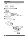
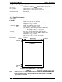
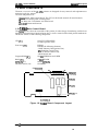
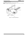
Figure 1-1 shows the an exterior view of the LX-105O+.
edge guides
‘aperguideSp.per-re,e.e
lever
vaver-tension unit
/
control panel
P
P
AC i n l e t ’
/
power switch
Figure 1-1. Exterior View of the LX-105O+
Rev. A
1-1
LX-105O+ Service Manual
General Description
Table 1-1 lists the optional units available for the LX-1050+.
Table 1-1. Options for LX-105O+
Cat. No.
8143
New Serial Interface Board
C82302*/C82304*
32KB Serial Interface
C82303*
32KB Parallel Interface
8165
IEEE-488 Interface Board
C80624*
Single Bin Cut Sheet Feeder
i C80014*
8755
1-2
Description
[ PullTractorUnit
Ribbon Cartridge
Rev. A
General Description
LX-105O+ Service Manual
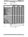
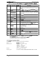
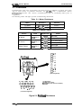
1.2 SPECIFICATIONS
This section provides detailed statistics for this printer.
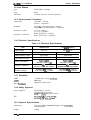
1.2.1 Printing Specification
Printing Method:
Serial, impact, dot matrix
Pin Configuration:
9 wires (diameter 0.29rnm)
#1
#2
#3
#4
#5
b
&--=-
0.29 mm
0.35 mm(l/72”)
I
#8
#7
#8
#9
Figure 1-2. Pin Configuration
Print speed:
Bi-directional printing with logical seeking (Text mode)
Uni-directional (left to right) printing (Bit image mode)
See Table 1-2.
Printable columns
See Table 1-2.
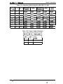
Print direction:
Table 1-2. Print Speed and Printable Columns
Printable Columns
Print Speed
Pica (10 cpi)
136
200 Cps
Elite (12 cpi)
163
240 CpS
Double-width pica
68
100 Cps
Emphasized pica
136
100 Cps
Double-width emphasized pica
68
50 Cps
Condensed pica (17 cpi)
233
171 Cps
Double-width condensed pica (17 cpi)
115
86 Cps
Double-width elite
81
120 Cps
Condensed elite (20 cpi)
272
200 Cps
NLQ pica (1 O cpi)
136
40 Cps
NLQ elite (12 cpi)
163
48 CpS
Type of Letters
Rev. A
1-3
LX-105O+ Service Manual
General Description
lot
matrix
format:
9 X 9 Text mode (Draft)
18X 20 Text mode (NLQ
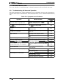
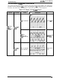
Ytaracter sets:
~haracter tables:
13 international character sets
See Table 1-3.
Table 1-3. Character Tables
SW)ck[d
India
Model
l?~su~ln
Latin
Model
South
E$;mg~
ITALIC
o
0
0
0
0
PC437 (US/ Standard Europe)
o
0
0
0
0
PC850 (Multilingual)
o
x
x
x
x
PC860 (Portuguese)
o
x
x
x
x
PC863 (Canadian-French)
o
x
x
x
x
PC865 (Nordic)
o
x
x
x
x
PC866 (Russian)
x
x
o
x
x
PC855 (Cyrillic)
x
x
o
x
x
PC852 (East Europe)
x
x
x
o
x
PC857 (Turkish)
x
x
x
x
o
PC437 Greek
x
x
x
x
o
PC869 (Greek)
x
x
x
x
o
Bulgaria
x
x
o
x
x
MAZOVIA (Poland)
x
x
x
o
x
Code MJK (CSFR)
x
x
x
o
x
ISO Latin IT (Turkish)
x
x
x
x
o
ISO 8859-7 (LatitiGreek)
x
x
x
x
o
Character Table
Font:
Draft, NLQ Roman, NLQ Saris Serif
Control code:
Esc/P-81
Standard, Latin, and South Europe model compatible with LX-105O
India and Russian model compatible with FX-1OOO (except IBM
mode)
Standard, Latin, and South Europe model: 4K bytes
India and Russian model: IK bytes
Input buffer:
1-4
Rev. A
General Description
LX-105O+ Service Manual
1.2.2 Paper Handling Specification
1/6 inch or 1/8 inch, or programmable in units of 1/216 inch
Approximately 95 ms (1/6 inch line feed)
Approximately 75 ms (1/6 inch in page feed)
Friction feed
Tractor feed (push tractor: standard, pull tractor: optional)
Line spacing:
Line feed speed:
Paper feed method:
Rear
Paper insertion:
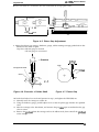
1.2.3 Paper Specification
Useable paper:
<Cut sheet>
Width: 182 to 364 mm (4 to 14.3 inch)
Length: 182 to 364 mm (4 to 14.3 inch)
Thickness: 0.065 to 0.14 mm (0.0025 to 0.055 inch)
Weight: 45 to 78 Kg (14 to 24 lb)
Width: 101 to 406.4 mm (4 to 16 inch)
Copies: 3 sheets (1 original 2 copies)
Total thickness: 0.065 to 0.25 mm (0.0025 to 0.010 inch)
Weight: 45 to 70 Kg (14 to 22 lb)
34 to 50 Kg (12 to 15 lb)-- copy paper
Size: No. 6 (166X 92 mm), No.1O (240X 104 mm)
Total thickness: 0.16 to 0.52 mm (0.0063 to 0.0197 inch)
Weight: 39 to 78 Kg (12 to 24 lb)
Size: 63.5 X23.8 mm (2.5 inch X 15/16 inch)
<Continuous paper>
<Envelope>
<Label>
Cut sheet
Printing Area:
3 mm min.
I
t--i
—
-#
—
3 mm min.
22 mm min.
Note 1
Printable area
I
22 mm min.
Note 2
Figure 1-3. Printable Area - Cut Sheet
Notes:
Rev. A
1. In the area from 8.5 mm to22mm from the top ofpapec itisprintable butpaper-feed
is not assured.
2. In the area from 13.5 mm to 22mm from the bottom of the paper, itisptintable but
paper-feed is not assured.
1-s
LX-105O+ Service Manual
General Description
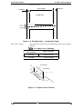
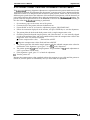
Continuous paper
345.4 mm max.
I
13 mm min.
➤ 4---D
I
13 mm min.
o
o
Printable area
0
0
0
0
0
0
0
.————————————
n
u
c1
0
0
0
0
0
0
Figure 1-4. Printable Area - Continuous Paper
The adjust lever must be set to the proper position for the paper
thickness.
Adjust lever settings
Table 1-4. Adjust Lever Settings
I
I
Lever position
0.06 to 0.18 mm
2nd step
I
Paper Thickness
I
I
3rd step
0.19 to 0.25 mm
2’nd position
4’th position
\@
Figure 1-5. Adjust Lever Position
s?
1-6
Rev. A
General Description
LX-105O+ Service Manual
1.2.4 Ink Ribbon
Type:
#8755 Ribbon Cartridge
Color:
Reliability:
Black
3 million characters at 14 dots/character
1.2.5 Environmental Conditions
Temperature:
-30 to60“C - Storage
5to35“C - Operation
Humidity:
5 to 85 YO RH (no condensation) - Storage
10to801%0 RH (no condensation) - Operation
Resistance to shock:
2 G, 1 ms - Storage
1 G, 1 ms - Operation
0.50 G (55 Hz max.) - Storage
0.25 G (55 Hz max.) - Operation
Resistance to vibration:
1.2.6 Electrical Specifications
Table 1-5. Electrical Specifications
I
Item
Rated voltage
120V Version
I
220- 240V Version
120 V AC
I
220- 240V AC
103.5 to 132V
198 to 264V
Rated frequency range
50 to 60 Hz
50 to 60 Hz
Input frequency range
49.5 to 60.5 Hz
49.5 to 60.5 Hz
Input voltage range
Power consumption
Insulation resistance
Dielectric strength
Approx. 28W
(Self test in draft 10 cpi)
Approx. 28W
(Self test in draft 10 cpi)
I
1
10 M(2, min.
10 MQ, min.
(between AC line and chassis)
(between AC line and chassis)
AC 1000 V rms 1 minute
or AC 1200 V rms 1 second
I
AC 1250 V rms 1 minute
or AC 1500 V rms 1 second
1.2.7 Reliability
MCBF:
MTBF:
3 million lines (except printhead)
6000 POH
Life of Printhead:
200 million strokes/wire
1.2.8 Safety Approval
Safety Standards:
RFI:
UL4785th(U.S. version)
CSA22.2 #220. (U.S. version)
VDE 0806 (TIN) (European version)
VfR.243 (VDE 0878 Part 3, Part 30)
E~550~ (CISPR P~b.22) ~lass B”
1.2.9 Physical Specifications
Dimensions
Weight
Rev. A
619.3 mm (Width) x 339 mm (Depth) x 141 mm(Height),
excluding knobs
8.80 Kg
LX-105O+ Service Manual
General Description
1.3 INTERFACE OVERVIEW
The LX-105O+ is equipped with the following external interfaces;
■
■
Centronics parallel interface
Optional Type A interface
1.3.1 Parallel InterFace
Data Format
Synchronization
8-bit parallel
Handshaking
By BUSY and ACKNLG signal
Ill-compatible
By STROBE pulse
Signal Level
Adaptable Connector
57-30360 (arnphanol) or equivalent
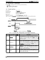
Table 1-6 shows the comector pin assignments and signal functions of the parallel interface.
BUSY
$1
/
ACKNLG
\
7p.a. approx. 5ps. approx.
DATA
STROBE
5ps. min.
5w. min.
5ps. min.
Figure 1 - 6 . D a t a T r a n s m i s s i o n Timing
Table 1-6. Connector
Pin No.
1
2-9
1-8
Signal Name
STROBE
DATA 1-8
Pin Assignments and Signal Functions
1/0
I
Description
The STROBE pulse is used to read data from the host
computer. The pulse width must be 0.5p.s or more.
Normally, it is HIGH, and data is latched with rising ~i
edge of this signal.
I
DATA 1-8 are parallel data bits. When one of these
signals is HIGH, the data bits is 1; when LOW, the data
bits is O. The most significant bit ( MSB) is data 8. The
signal state must be maintained for 0.5ps on either side
of STROBE signal’s active edge.
10
ACKNLG
o
ACKNLG is an acknowledge pulse with a width of
approximately 10P.s. This signal goes LOW upon the
completion of data reception, to indicates that the printer
is ready to receive further data.
11
BUSY
o
The BUSY signal informs the host computer of the
printer’s status. When this signal is HIGH, the printer
cannot accept further data.
Rev. A
General Description
LX-105O+ Sewice Manual
—.
.
.
.
-.
.
—
.
.
.-
.
.
Table 1-6. Connector Pin Assignments and Signal Functions (Cont.)
Pin No.
Signal Name
1/0
Description
12
PE
o
This signal indicates whether paper is available in the
printer or not. A HIGH level indicates a no paper
condition.
13
SLCT
o
pulled up to +5V though 3.3KQ resistor in the
14
AUTO FEED XT
1
If this signal is set to LOW, the printer automatically
performs one line feed upon receipt of a CR (carriage
return) code.
15
NC
Not USSd.
16
GND
Signal ground
17
CHASSIS GND
-
Chassis ground.
18
NC
.
Not USSd.
19-30
GND
31
INIT
print,er. ,
Twisted-pair return signal ground.
I
o
If this signal goes LOW, the printer is initialized. The
pulse width of this signal must be 50p.s or more.
This signal goes LOW if the printer:
- has a fatal error.
- runs out of paper.
- off line.
32
ERROR
33
GND
Signal ground.
34
NC
Not Used
35
+5V
Pulled up to +5 V through 3.3 KQ resistor in the printer.
36
SLCT IN
Notes:
I
The DC1/DC3 code is only valid when this signal is
HIGH.
A// interface conditions are based on 7ZL /eve/s. Both the rise andfa// times of all signals
must be /ess than 0.2 p.s.
The AUTO FEED-XT signal can be set LOW by DIP sw”tch 2-4.
The SELECT IN signal can be set LOW by jumper 1.
1.3.2 Optional Interface #8143
The LX-105O+ can use the non-intelligent serial interface board #8143.
Tyep:
Synchronization:
Protocol:
Transfer speed:
Rev. A
RS-232C or current loop
Asynchronous start-stop system
Start bit:
1 bit
Stop bit:
1 bit or more
Data length: 7 or 8 bits
Parity:
Odd, Even or none
X-ON/X-OFF or DTR control
75,110,134.5,150,200, 300,600,1200,1800,2400, 4800, and 9600
1-0
LX-105O+ Service Manual
General Description
1.4 PRINTER OPERATIONS
This section describes the basic operations of the printer.
1.4.1 Control Panel
The control panel of this printer contains four non-lock type push buttons and four LED indicators
for easy ope;ation of the various printer function.
[Buttons]
D POWER
0 ON LINE
D READY
m PAPER
OFF LINE
OUT
NLQ
III I
CONON J
D E N S E D OFf= J
LOAD/EJECT
ROMAN
JJ
SANS SERIF J J J
FORM FEED ~
J
II
LINE FEED
Figure 1-7. Control Panel
ON LINE:
Switches printer status between on line and offline.
FORM FEED:
When the printer is off line, press this button to eject a single sheet of paper
LINE FEED:
LOAD/EJECT:
or to advance continuous paper to the top of the next page.
When the printer is off line, press this button to advance the paper one line,
or hold it down to advance the paper continuously.
This button is used to feed the paper to the loading position, or to eject paper
that is already loaded. Paper is ejected forward if the paper-release lever is
set to the single-sheet position, or is ejected backward (removed from the
paper path) if the release lever is set to the continuous paper position.
[Indicators]
POWER:
On when the power switch is on and power is supplied.
READY:
On when the printer is ready to accept input data. Flickers while data is
printed.
PAPER OUT:
On when the printer is out of paper or when continuous paper ia in a
standby position. The printer also beeps when it is out of paper.
ON LINE:
On when the printer is on line and ready to accept data from the computer.
When this indicator is blinking, the micro-adjustment feature can be used.
1-10
Rev. A
LX-105O+ Service Manual
General Description
1.4.2 SelecType Functions
SelecType allows the user to choose fonts and the printing mode easily. This function provides for
selection of Draft, Roman, or Saris Serif fonts and selection of normal printing or condensed
printing modes. SelecType is effective only when the printer is ON LINE and not printing.
To select Roman or Saris Serif, press the NLQ button. A buzzer sounds when the NLQ button is
pressed. When it sounds twice, the Roman font is selected. When it sounds three times, the Saris
Serif font is selected.
To select the Draft font, press the DRAFT button. The buzzer will sound once, indicating that the
DRAFT font is selected.
To set for condensed printing when the printer is in the print mode, press the CONDENSED button
once (the buzzer will sound once), and the printer will enter the condensed print mode.
To cancel condensed printing, press the CONDENSED button again. After you press the button,
the buzzer sounds twice to tell you that condensed printing is canceled.
1.4.3 Micro Adjustment
By pressing the FORM FEED or LINE FEED buttons immediately after loading paper or when
using the tear-off feature, you can make tine adjustment to the loading and tear-off positions.
1.4.4 Panel Operation at Power ON
The following functions can be activated at power on by holding down the specified button on the
control panel.
Self-test mode:
Hex Dump mode:
To begin printing the self-test in the Draft mode, turn the printer ON while
pressing the LINE-FEED button. To begin printing the self-test using the
NLQ mode (Near Letter Quality), press FORM FEED and hold it down, then
turn the printer power ON.
Self-test printing can be stopped or started by pressing ON-LINE (ON-LINE
indicator is not lit). To finish the self-test, stop the printing by pressing the
ON-LINE switch then turn OFF the printer power.
The firmware revision number is printed as the first line of the self-test, and
subsequently, current DIP switch settings are printed.
The printer enters the HEX-DUMP mode when it is powered on while the
LINE-FEED and FORM-FEED buttons are pressed down.
In the HEX-DUMP mode, the hexadecimal representation of the input data is
printed out, along with corresponding ASCII characters. This function is
valuable for checking the data the printer has received from the host. If input
data is a control code rather than a character code, a period (.) is printed in
the ASCII column.
1-11
Rev. A
,!
L.X-1050+ Service Manual
General Description
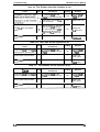
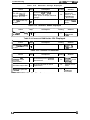
1.4.5 DIP Switch Settings
The two DIP switches are located on the side of the printer and function as shown in Tables 1-7
throum 1-10. Note that the status of the DIP switches is read only at power on or upon receipt of
the INIT signal.
Table 1-7. Settings for DIP Switch
I
I
I
Description
SW No.
1-2
1
1-3
1-4
Shape of Zero
12 cpi
10 cpi
0
0
OFF
OFF
1
I
OFF
OFF
See Table 1-10.
Page length
1-5 I Tableselection
I Italics
I Graphics
1-6
1-7
1-8
Character table selection
See Table 1-8 or 1-9.
2-1
Short tear-off
Invalid
I
I
2-3
Skip over perforation
2-4
AUTO FEED XT signal internally
fixed or not
1
I
I
Invalid
I
1 inch
OFF
1
Depends on
external signal
Fixd t. Low
OFF
I
None
I
OFF
ON
ON
ON
Valid
Valid
Cut sheet feeder control
2-2
Faoto~
Settings
OFF
ON
Character Pitch
1-1
I
OFF
OFF
Table 1-8. International Character Set Selection (DIP SW 1-5: OFF)
Sw 1+ Sw 1-7 Sw 1-8
Country
Sw 1-6 Sw 1-7 Sw 1-8
Country
ON
ON
ON
U.S.A
OFF
ON
ON
Denmark
ON
ON
OFF
France
OFF
ON
OFF
Sweden
OFF
ON
Germany
ON
I
ON
I OFF I OFF I
1-12
U.K.
I
OFF
II
OFF
I
I
OFF
OFF
I
I ON
Italy
OFF
Spain
I
Rev. A
General Description
LX-105O+ Service Manual
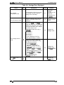
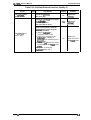
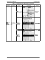
Table 1-9. Character Table Selection (DIP SW 1-5: ON)
Sw 1-6 Sw 1-7 Sw 1-8
India
version
~:pj:;d
:?:/::
Latin
Version
South
Europe
Version
ON
ON
ON
PC437
PC437
PC437
PC437
PC437
ON
ON
OFF
PC850
PC437
PC866
PC852
PC857
ON
OFF
ON
PC860
PC437
PC869
MAZOWIA
ISO Lat. IT
ON
OFF
OFF
PC863
PC437
Bulgaria
Code MJK
PC437G.
OFF
ON
ON
PC865
PC437
PC437
PC437
PC869
OFF
ON
OFF
PC437
PC437
PC437
PC437
1S088597
OFF
OFF
ON
PC437
PC437
PC437
PC437
PC437
OFF
OFF
OFF
PC437
PC437
PC437
PC437
PC437
I
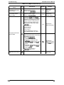
Table 1-10. Page Length Selection
w
ON
OFF
12inch
OFF
ON
8.5 inch
ON
ON
70/6 inch
1-13
Rev. A
,
I
LX-105O+ Service Manual
General Description
1.4.6 Buzzer Operation
The buzzer sounds under the following conditions:
BEL code:
Carriage trouble:
PaperQut:
Abnormal voltage:
Incorrect SRAM:
Incorrect RAMinside CPU:
Recognition of panel
operation:
Factory setting:
Sheet ejection failure
(in CSF mode):
Illegal paper release/
unrelease:
The buzzer sounds for 0.1 second when a BEL code is input.
Beeps 6 times, pausing briefly after 3rd beep.
Beeps 20 times, pausing briefly after every 4 beeps.
Beeps 5 times, pausing after every beep.
Beeps 8 times, pausing briefly after every 2 beeps.
Beeps indefinitely until power OFF.
Beeps 1 or 2 or 3 times in setting print mode.
Beeps once when the value under micro-adjusting is equal to the
factory-set value.
Beeps 20 times, pausing briefly after every 4 beeps.
Beeps continuously when the paper release lever is changed when
the paper is in the paper path.
Beeps until the lever is changed again or the paper is completely out
of the path.
1.4.7 EEPROM Reset
This printer has EEPROM, it memorized SelecType settings, position of continuous paper, and
bi-directional printing adjustment value. EEPROM reset operations are only required after the
main board replacement, EEPROM replacement, or printer mechanism replacement.
The EEPROM is cleared, when the printer power on while FF and LOAD/EJECT switches are
pressed.
1-14
Rev. A
Ganeral Description
LX-105O+ Service Manual
1.5 MAIN COMPONENTS
The main components of the LX-105O+ printers are designed for easy removal and replacement to
maintain/repair the printers.
The main components are:
Cl TAMA board: Main control board. The CPU on this board controls all main functions.
D TAPNL-W control panel: Control panel.
Cl TAa filter unit: Transformer and filter board.
D M-3D60: Printer mechanism.
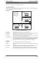
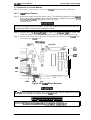
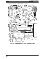
1.5.1 TAMA Main Control Board
The TAMA board is the main controller of this printer. It takes charge of interfacing with the host
computer and processing of received print data, as well as control of the whole printer mechanism.
This-board consists of the following components.
CPU (2C):
8-bit CPU (PPD781OHG)
15 MHz operation clock
E05A30
Includes the following functions:
- MMU (Memory Management Unit)
- IFU (Interface Control Unit)
- PCU (1/0 Port Control Unit)
- Head control unit
Gate-array (3B):
Program ROM (3C):
256 Kbit EPROM or mask ROM
RAM (3D):
EEPROM (lC):
64 Kbit PS RAM
256 bit EEPROM
CR Motor driver (1A):
SLA7020M
GA E05A30(3B)
“ PROM(3C)
“ RAM(3D)
-
-
CPU(2C)
EEPROM(l C)
SLA7020M(1A)
Figure 1-8. TAMA Board Component Layout
Rev. A
1-15
,
LX-105O+ Service Manual
General Description
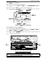
1.5.2 TAa Filter Unit
The TAa filter unit contains a power cord (120V Version) or AC inlet (220/240V Version), power
switch, fuse filter circuit, and power transformer.
120V Version
220/240V Version
Figure 1-9. TAa Filter Unit
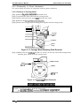
1.5.3 Printer Mechanism (M-3D60)
The M-3D60 printer mechanism was developed specifically for the LX-105O+ printer. Its
components include:
Carriage motor
Carriage mechanism
Paper feed motor
Paper feed mechanism
Ribbon feed mechanism
Printhead
Sensors
Figure 1-10. Printer Mechanism (M-3D60)
1-16
Rev. A
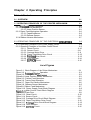
Chapter 2 Operating Principles
Table of Contents
2-1
2.1 OVERVIEW
2-1
2.2 OPERATING PRINCIPLES OF THE PRINTER MECHANISM
2.2.1 Printhead Printing Operation . . . . . . . . . . . . . . . . . . . . . . . . . . . . . . . . . . 2-2
2.2.2 Carriage Drive Mechanism . . . . . . . . . . . . . . . . . . . . . . . . . . . . . . . . . . . 2-3
2.2.2.1 Home Position Sensor . . . . . . . . . . . . . . . . . . . . . . . . . . . . . . . . 2-3
2.2.3 Paper Feed Mechanism Operation . . . . . . . . . . . . . . . . . . . . . . . . . . . . . 2-4
2.2.3.1 PaperEndSensor. . . . . . . . . . . . . . . . . . . . . . . . . . . . . . . . . . . . 2-6
2.2.3.2 Release Sensor.. . . . . . . . . . . . . . . . . . . . . . . . . . . . . . . . . . . . . 2-6
2.2.4 Ribbon Advance Mechanism . . . . . . . . . . . . . . . . . . . . . . . . . . . . . . . . . . 2-7
2-8
2.3 OPERATING PRINCIPLES OF THE ELECTRICAL CIRCUITRIES
2.3.1 Operating Principles of the Power Supply Circuit . . . . . . . . . . . . . . . . . . 2-8
2.3.2 Operating Principles of the Main Control Circuit . . . . . . . . . . . . . . . . . . . 2-9
2.3.2.1 Reset Circuits.. . . . . . . . . . . . . . . . . . . . . . . . . . . . . . . . . . . . . 2-10
2.3.2.2 Sensor Circuit . . . . . . . . . . . . . . . . . . . . . . . . . . . . . . . . . . . . . . 2-11
2.3.2.3 Carriage Motor Drive. . . . . . . . . . . . . . . . . . . . . . . . . . . . . . . . . 2-11
2.3.2.4 Paper Feed Motor Drive Circuit. . . . . . . . . . . . . . . . . . . . . . . . . 2-12
2.3.2.5 Printhead Drive Circuit . . . . . . . . . . . . . . . . . . . . . . . . . . . . . . . 2-13
2.3.2.6 Host Interface.. . . . . . . . . . . . . . . . . . . . . . . . . . . . . . . . . . . . . 2-14
2.3.2.7 EEPROM Circuit. . . . . . . . . . . . . . . . . . . . . . . . . . . . . . . . . . . . 2-15
List of Figures
Figure 2-1 Block Diagram of the Printer Mechanism . . . . . . . . . . . . . . . . . . . . 2-1
Figure 2-2 Printhead-Printing Operation . . . . . . . . . . . . . . . . . . . . . . . . . . . . . . 2-2
Figure 2-3. Carriage Drive M~chanism . . . . . . . . . . . . . . . . . . . . . . . . . . . . . . . 2-3
Figure2-4. Home Position Sensor Mechanism . . . . . . . . . . . . . . . . . . . . . . . . . 2-3
Figure 2-5. Friction Feed Operation.. . . . . . . . . . . . . . . . . . . . . . . . . . . . . . . . . 2-4
Figure 2-6. Tractor Feed Operation . . . . . . . . . . . . . . . . . . . . . . . . . . . . . . . . . . 2-5
Figure 2-7. Paper End Sensor Mechanism . . . . . . . . . . . . . . . . . . . . . . . . . . . . 2-6
Figure 2-8. Release Sensor Mechanism . . . . . . . . . . . . . . . . . . . . . . . . . . . . . . 2-6
Figure2-9. Ribbon Feed Mechanism . . . . . . . . . . . . . . . . . . . . . . . . . . . . . . . . 2-7
Figure 2-10. Power Supply Circuit Block Diagram. . . . . . . . . . . . . . . . . . . . . . . 2-8
Figure2-11. Main Control Circuit Block Diagram. . . . . . . . . . . . . . . . . . . . . . . . 2-9
Figure2-12. Data Flow . . . . . . . . . . . . . . . . . . . . . . . . . . . . . . . . . . . . . . . . . . . 2-9
Figure 2-13. Reset Circuit . . . . . . . . . . . . . . . . . . . . . . . . . . . . . . . . . . . . . . . . 2-10
Figure 2-14 Sensor Circuit . . . . . . . . . . . . . . . . . . . . . . . . . . . . . . . . . . . . . . . 2-11
Figure 2-15 Carriage Drive Circuit Block Diagram . . . . . . . . . . . . . . . . . . . . . 2-11
Figure 2-16 Paper Feed Motor Drive Circuit. . . . . . . . . . . . . . . . . . . . . . . . . . 2-12
Figure 2-17 Printhead Drive Circuit Block Diagram . . . . . . . . . . . . . . . . . . . . 2-13
Figure 2-18 Host Interface.. . . . . . . . . . . . . . . . . . . . . . . . . . . . . . . . . . . . . . 2-14
Figure 2-19 EEPROM Circuit . . . . . . . . . . . . . . . . . . . . . . . . . . . . . . . . . . . . . 2-15
List of Tables
Table 2-1. Ribbon-Feed Gear Train. . . . . . . . . . . . . . . . . . . . . . . . . . . . . . . . . . 2-7
Table 2-2. Voltage Applications . . . . . . . . . . . . . . . . . . . . . . . . . . . . . . . . . . . . . 2-8
Table 2-3. Functionsofthe Main ICand Circutis . . . . . . . . . . . . . . . . . . . . . . . 2-10
Table 2-4. Phase-Excitation Method . . . . . . . . . . . . . . . . . . . . . . . . . . . . . . . . 2-11
Operating Principles
LX-105O+ Service Manual
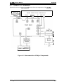
2.1 OVERVIEW
This section describes the operating principles of the printer mechanism and the electrical circuits
of the LX-105O+.
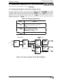
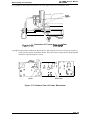
2.2 OPERATING PRINCIPLES OF THE PRINTER MECHANISM
The LX-105O+ printer mechanism is composed of the printhead unit, paper feed mechanism,
carriage drive mechanism, and various sensors. The figure below shows a block diagram of the
printer mechanism.
Phase
Phase
CR HOME
PE
v
v
Stepper Motor
Stepper Motor
Q
carnage
Home
Printhead
................
Paper End
Paper Feed
Carriage Drive
1
I
1160nlStep
or
ll120*lStep
RELEASE
A
A
I
I
11216 ’lStep
FRICTIOtV
TRACTOR
1
Release
Lever
Position
Figure 2-1. Block Diagram of the Printer Mechanism
Rev. A
2-1
LX-105O+ Service Manual
Operating Principles
2.2.1 Printhead Printing Operation
The dot-wire operation during printing is as follows. When the head-driving coil for a dot wire is
energized, the actuating plate, which is engaged to one end of the dot wire, is attracted to the iron
core, and drives the dot wire toward the platen. The dot wire forcefully pushes both ribbon and
paper against the platen, causing a dot to be printed.
When the head-driving coil is deenergized, the actuating plate spring causes the actuating plate to
return to its initial position. After striking the platen, the dot wire also returns to its initial position,
partly in response to the impact energy, and partly as a result of the wire-resetting spring. The dot
wire then remains engaged to the actuating plate until it is driven again.
Printhead specifications areas follows:
Solenoids:
9 solenoids
Wire Diameter:
Drive Voltage:
0.29 mm
24 VDC * 10Yo
Coil Resistance:
19.2 ~ 1.0 fi2 at 25° C
Platen
Wire
Dot
Wire Resetting Spring
.-.
Stnnner
-r F-
\
\
‘7”*
\
\
\
‘4P+—+1
Ilxl
/
Ribbon
Actuating Plate
~
T
!’
cl--k-e
Paper
~~l~HeadDrivin9Coi,
Act;ating plate SPrin9
Figure 2-2. Printhead Printing Operation
Rev. A
2-2
,
Operating Principles
LX-1050+ Service Manual
2.2.2 Carriage Drive Mechanism
The carriage mechanism includes the printhead, the carriage, the timing belt, the carriage motor,
and the platen.
The timing belt is connected to the bottom of the carriage. The belt is driven by the carriage motor
and moved via the beltdriven pulley. The printhead is mounted on the carriage, and the entire
unit is moved right and left along the carriage guide shaft and plate.
Carriage motor specifications are as follows:
Type:
Drive Voltage:
4-phase, 48-pole step motor
Coil Resistance:
11 G2 k 77. at 25°C
Current Driving:
0.36 A * IO%(Typical) (Draft Printing)
0.28 A * IO%(Typical) (NLQ Printing)
Holding: 0.09 A f IWO
24 V k
MY/o
Left
-%’”
.carr-
Figure 2-3. Carriage Drive Mechanism
2.2.2.1 Home Position Sensor
Following figure shows the home position sensor. The sensor switch is ON when the carriage is at
the home position.
Figure 2-4. Home Position Sensor Mechanism
Rev. A
2-3
LX-105O+ Service Manual
Operating Principles
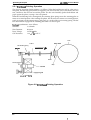
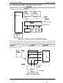
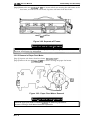
2.2.3 Paper Feed Mechanism Operation
Friction feeding is used for cut sheets, and push tractor feeding is used for fanfold paper.
Friction-Feed Operation
The paper is held against the platen by paper-feed rollers. The paper-feed motor rotates the platen
gear, via the paper-feed reduction gear, in the direction shown in following figure. Because of the
friction between the paper-feed rollers and the platen, the rotation of the platen gear causes the
paper to be fed. The feeding direction is indicated by the arrow in the Figure.
The paper is held against the platen by the spring force of the paper-feed rollers, and can be
released by shifting the paper-release lever forward.
Platen
,ap~en,ion
,O,,er
paper (Cut Sheet)
p
,(
ion Gear
Motor
Paper
d Motor
Figure 2-5. Friction Feed Operation
2-4
Rev. A
Operating Principles
LX-105O+ Service Manual
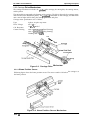
Push Tractor Feed Operation
When the push tractor unit is used, the paper is set such that its holes mesh with the tractor pins
along the tractor belt. The paper feed motor is driven and, via the pinion on the motor shaft, rotates
the gears in the direction shown in following figure, rotating the tractor belts. This causes the paper
advances in the direction indicated by the arrow. When push tractor feeding is used, the pressure
of the paper feed rollers against the platen is released by moving the paper release lever to its
forward setting.
ear
Gear
Motor
Figure 2-6. Tractor Feed Operation
Paper-feed motor specifications are as follows:
Type:
Drive Voltage:
4phase, 48-pole step motor
Coil Resistance:
40 ohms* 79!. at 25°C
2-2 phase
Phase Excitation:
Current:
Rev. A
24 VDC * 10Yo
Maximum, 1.1A (Rush Current, 26.4 VDC)
Driving: 0.30 A (Typ., 480 pps, 24 VDC)
Holding: 0.06 A *20 rnA
Driving Frequency: 480 PPS
2-5
LX-105O+ Service Manual
Operating Principles
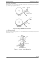
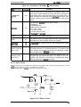
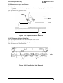
2.2.3.1 Paper End Sensor
Following figure show the paper end sensor. This sensor switch is ON when no paper is in place
(e.g., when the paper supply has run out.).
Paper
~
2
“Paper present”
Figure 2-7. Paper End Sensor Mechanism
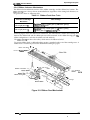
2.2.3.2 Release Sensor
The release sensor senses the position of the release lever in order to detect whether tractor feed or
friction feed is in effect.
Fric/ion/Tractor Sensor
Figure 2-8. Release Sensor Mechanism
24
Rev. A
Operating Principles
LX-105O+ Service Manual
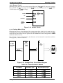
2.2.4 Ribbon Advance Mechanism
The ribbon-feed mechanism consists of the ribbon cartridge and the ribbon-feed section. The
ribbondriving gear is always driven counterclockwise (regardless of the timing belt direction) via
the gear trains shown in following table.
Table 2-1. Ribbon-Feed Gear Train
1
Direction of Carriage
Movement
I
Gear Linkage
Left to right (arrow e)
Beltdriven pulley-+ Platen gear (1) ~ Platen gear(2)
~ Ribbon-drivin9 gear
Left to right (arrow d)
Beltdriven pulley- Platen gear (1) - Platen gear(3)
- Platen gear (4) - Ribbondriving gear
Following figure shows the ribbon-feed mechanism. The inked ribbon is held in the cartridge case
between the ribbon-feed and the ribbon-pressure roller mounted on the ribbon-driving gear. The
ribbon configuration is such that the ribbon can feed endlessly.
The ribbondriving gear drives the rollers, which causes the ribbon to be fed.
To prevent ribbon slack, a ribbon-breaking spring is attached at the exit of the cartridge case. A
ribbon mask is installed to prevent the ribbon from staining the paper.
G
Ribbon Feed Roller
b’
R i b b o n ‘ress”re ‘O’’er\
>
-
Ribbon Transmission Gear
P,ane;:’;ar
Ribbon Driving Gear
‘
\
“H
Breaking
Sp;ing
-&.
m%’d
&
Carriage
\\\
Figure 2-9. Ribbon Feed Mechanism
2-7
Rev. A
,
LX-105O+ Service Manual
Operating Principles
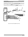
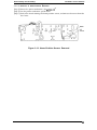
2.3 OPERATING PRINCIPLES OF THE ELECTRICAL CIRCUITRIES
This section describes principles of electrical circuitries.
2.3.1 Operating Principles of the Power Supply Circuit
using the TAa Fiher Unit (which
combines a filter and a power transformer) and the T14NfA board. The Ac input passes first
through the filter circuit, where line noise is removed, and is then set to the transformer, where it is
stepped down into two separate voltages: AC 26V and AC 12C. The transformer output is sent to
the power circuits on the TAMA board, which converts the power to the DC voltages (see below)
The electrical power required by this mechanism is developed
required for operation.
Table 2-2. Voltage Applications
Purpose
Voltage
I
+5 VDC
Logic circuit voltage
Holding voltage for paper feed motor
Others
+24 VDC
Carriage motor drive voltage
Paper-feed motor drive voltage
Printhead drive voltage
I
Voltage for the optional l/F
+12 VDC
I
TAa Filter Unit
I
o-AC
Filter
IN
Circuit
*
TAMA Board
Stepdown
Transformer
——1
26 VAC
Full-wave
+24 VDC
rectifier
and
regulator
circuit
+ +24 VDC
smoothing
I
circuit
12 VAC
I
~1
,1
—
Full-wave
rectifier
and
smoothing
circuit
+24 VDC
regulator
circuit
+ +5 VDC
➤ +12 VDC
Figure 2-10. Power Supply Circuit Block Diagram
2-8
Rev. A
Operating Principles
LX-105O+ Service Manual
2.3.2 Operating Principles of the Main Control Circuit
The printer CPU is an 8-bit CPU ~D7810HG running at 15 MHz. It oversees control of all the
components of the printer. The E05A30 gate array contains various memory management functions
that control the assignment of the memory and 1/0 areas.
Bm
CPU
vPD781OHG
(2C)
~c”’””’
E
E05A30
(3B)
I
CR motor
driver
Control Panel
Parallel l/F
EIE
m
Figure 2-11. Main Control Circuit Block Diagram
Table 2-3 lists the functions of the components and circuits of the printer. The CPU converts the
print data sent from the host computer to image data (the print image). The image data is then
loaded to RAM. Each line of data is processed sequentially. The CPU transfers the print data to the
printhead drive circuit. The CPU sends the printhead drive pulse to the printhead drive circuit. The
length of this pulse corresponds to the pnnthead drive voltage. The head drive circuit then outputs
the-head drive signal. -
Host
Computer
RAM
CPU
Print
Data
Data Input
●
Input
Buffer
—
Print Data
Convertor
tl
+24V line
1
I
Image Data
Transfer
L
+
Image
Buffer
—
Printhead Drive
L?ap’nthead
Figure 2-12. Data Flow
Rev. A
2-9
I
LX-105O+ Service Manual
Operating Principles
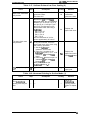
Table 2-3. Functions of the Main IC and Circuits
Looation
Functions
2C
Receives data from the host computer and loads the data to the
input buffer in RAM. Expands the input data held in the buffer to
create image data. Loads this image data to the image buffer in
RAM. Transfers the image data to the printhead drive circuit. Also
controls various parts of the printer mechanism, such as the
motors.
E05A30
3B
The gate array E05A30 functions areas follows
1. Parallel l/F
2. Address decoder
3. Data address multiplexer
4. PF motor control
5. CR motor control
6. Control panel LED drive
7. Printhead drive oontrol
ROM
3C
This ROM memory program and fonts.
RAM
3D
This RAM is used as an input data buffer and image buffer for
expanding data, and as working area for the program.
EEPROM
Ic
The EEPROM has a 256-bit memory, and remembers the current
paper position.
—
The paper feed motor drive circuit drives the paper feed motor.
The paper feed motor is a 4 phase-step motor. The rotation of the
motor (position and speed) is controlled by outputting the phase
switching signal by the E05A30 gate array.
—
The carriage motor drive circuit drives the carriage motor. The
carriage motor is a 4 phase-step motor. The rotation of the motor
(position and speed) is controlled by outputting the phase
switching signal by the E05A30 gate array.
IC and Circuits
vPD781 OHG
Paper feed motor
drive circuit
Carriage motor
drive circuit
2.3.2.1 Reset Circuit
11-tis circuit generates the signal that initializes the printer, and is made by monitoring the +5 and
+24V voltages when the power is switched ON and OFF.
The reset signal line is comect to the CPU and gate array 3B.
c15
A1015
MA165
+
+2J?!-P’
KIT
+5V4
R57
10K
R83
47K
)
I
k
R82
2.2K
ZD2
MA4036-M
RESET
C18
&
h
Figure 2-13. Reset Circuit
2-1o
Rev. A
Operating Principles
LX-105O+ Service Manual
2.3.2.2 Sensor Circuit
Following figure shows the sensor circuit in block diagram. The PAO of CPU port senses carriage
home position. The PA1 senses paper end. The PA2 senses release lever position. The AN5 of CPU
A/D convertor senses +24V line voltage.
HOME
PAO
PE
PA1
RELEASE
PM
+24V line
AN5
CPU
uPD7810HG
(2C)
Figure 2-14. Sensor Circuit
2.3.2.3 Carriage Motor Drive
Following figure shows a block diagram of the carriage motor drive circuit. In this circuit, the phase
switching for the carnage motor is directly executed not by the CPU, but by the gate array (3B),
which acts on the basis of the CPU phase data. SLA7020M drives the carriage motor with a
stabilized stabilized current.
The excitation system is determined by the firmware and is executed in accordance with the
carriage speed, as shown in Table 2-4.
1
GA
CPU
SLA
7020M
( 1A)
E05A30
(3B)
L PD78 10HG
(2 c)
o
M
b
Phase” Data
Figure 2-15. Carriage Drive Circuit Block Diagram
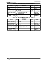
Table 2-4. Phase-Excitation Method
I
Rev. A
Drive Mode
Excitation Type
Drive Frequency Type
Mode 1
2-2 phase
1200 pps
Mode 2
2-2 phase
900 pps
Mode 3
1-2 phase
1200 pps
Mode 4
1-2 phase
900 pps
2-11
LX-1050+ Service Manual
Operating Principles
2.3.2.4 Paper Feed Motor Drive Circuit
The paper-feed motor drive circuit is shown in following figure. me paper-feed motor is a step
motor which can utilize 2-2 phase excitation. When the paper-feed signal PC2 is set to HIGH, Q20
and Q16 are turned on, and +24 V is supplied to the motor. When the paper-feed motor is not
driven, +5 V is supplied, via resistor R42 and diode D6, to hold the motor.
The paper feed motor is a 48-pole step motor and is open-loop controlled. When 2-2 phase
excitation is used to drive the motor, each step feeds the paper a distance of l/216th inch.
+5V
+24V
CPU
rffPD78 10HG
(2C)
R36
3.3K
A
A
,
I?44
5.6K
I
PC2
R45
5.6K
19
PFCOM
PFCOM
RI 16
33K
12
EO:\O
(3 B)
8
11
8
PFA
9
PFB
10
PFC
11
PFD
R87 3.3K
VAVAV
R89 3.3K
VAVAV
R86 3.3K
v VAV
R88 3.3K
Vhvf
7
GP
Figure 2-16. Paper Feed Motor Drive Circuit
PF A
PF B
PF C
PF D
Operating Principles
LX-105O+ Service Manual
2.3.2.5 Printhead Drive Circuit
Gate array E05A30 is used as an 8-bit + l-bit data latch. The CPU determines the pulse width for
the head-wire drive pulses from gate array E05A30 by monitoring the printhead drive power (+24
V line).
The E05A30 gate array includes circuitry to interface the CPU and the printhead. The data is output
to the printhead in the following sequence:
Print data is expanded in the image buffer as dot patterns. The CPU outputs the dot patterns to the
E05A30.
The data for pins 1 through 8 of the printhead is latched by HDl trough HD8 of the E05A30.
The data for pin 9 of the printhead is latched by HD9 of the E05A30.
After data latching, the pnnthead drive pulse width signal FIRE is output from the CPU’s event
counter. When the signal is LOW, the gate array will be open, so that the data from HD1 through
HD9 will be output.
The drive pulse width is adjusted using CPU port PC6.
CPU
/U PD78 10HG
(2C)
Printhead
Drive
Circuit
EO%30
(3 B)
--N
DATA
-1/
FIRE
--N
--l/
Print herd
L
●
Figure 2-17. Printhead Drive Circuit Block Diagram
Rev. A
2-13
LX-105O+ Service Manual
Operating Principles
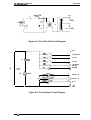
2.3.2.6 Host Interface
The host interface circuit is shown in following figure. STROBE pulses from the host computer pass
through the low-pass filter, consisting of R72 and C12, and flow into the STROBE terminal.
These pulses latch the parallel data and set the BUSY signal HIGH, so that subsequent data transfer
is inhibited.
At this time, the CPU, by reading address OCO02H, can detect whether the data from the computer
are latched in the gate array.
When the CPU determines that data have been latched, it proceeds to read the data. After the data
have been read, the gate array automatically resets its busy signal.
z
-1
2
u
u
a
-a
z<
V&
I
0 0 0
t-i 0
- . r) x x % x
m m m m
N
!+ & 1+ I+
m *
w
a
!s
K
,
N
10
w w
K
K
n
0
i-
k
4.
0
&
w m 1- :
0 n 0 n
Lnu-lmm
:11111%11 H-M
a
P
0
CDlnlo(n
- - - - - < < < <
Zzzz
Inlnmln
ID WUJW
- - - -
<<<<
Zzzz
t’i+
UC-)
Z
~
z
ua
o
Figure 2-18. Host Interface
2-14
Rev. A
Operating Principles
LX-105O+ Service Manual
2.3.2.7 EEPROM Circuit
The EEPROM stores in its memory the current feed position of continuously fed paper, as well as
the current panel settings. This memory is retained even after power is shut off.
EEPROM can memorize the current position of continuously fed paper, so that this information can
be maintained even if power goes off.
Following figure shows the EEPROM circuit. Note that this is external to the CPU’s memory space.
EEPROM is selected when CPU port PC5 goes HIGH. Once EEPROM has been selected, the data to
be sent is set in CPU Dort PB1, and is fed bit-by-bit to the EEPROM in line with rising-.pulses from
CPU port PC4’S clock: Data are read, bit-by-bitjin line with falling clock pulses.
The EEPROM receives commands to indicate whether to read or write data, and to indicate
addresses.
CPU
K PD78 10HG
(2C)
ER59256
( 1 c)
7
TEST
DI
3
DO
4
Cs
‘
CLK
2
10
9
22
T
R1 19
33K
21
PB 1
PBO
. PC5
PC4
RI 20
33K
777
Figure 2-19. EEPROM Circuit
Rev. A
2-15
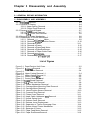
Chapter 3 Disassembly and Assembly
Table of Contents
3.1 GENERAL REPAIR INFORMATION
3-1
3-2
3.2 DISASSEMBLY AND ASSEMBLY
3.2.1 Printhead Removal . . . . . . . . . . . . . . . . . . . . . . . . . . . . . . . . . . . . . . . . . 3-2
3.2.2 Removal of Casing . . . . . . . . . . . . . . . . . . . . . . . . . . . . . . . . . . . . . . . . . 3-4
3.2.2.1 Upper Casing Removal. . . . . . . . . . . . . . . . . . . . . . . . . . . . . . . . 3-4
3.2.2.2 Control Panel Removal. . . . . . . . . . . . . . . . . . . . . . . . . . . . . . . . 3-6
3.2.3 Removal of Circuit Boards. . . . . . . . . . . . . . . . . . . . . . . . . . . . . . . . . . . . 3-7
3.2.3.1 TAMA Board Removal . . . . . . . . . . . . . . . . . . . . . . . . . . . . . . . . 3-7
3.2.3.2 TA-a Filter Unit Removal. . . . . . . . . . . . . . . . . . . . . . . . . . . . . . . 3-8
3.2.4 Removal of Printer Mechanism . .“. . . . . . . . . . . . . . . . . . . . . . . . . . . . . . 3-8
3.2.5 Disassembly of Printer Mechanism . . . . . . . . . . . . . . . . . . . . . . . . . . . . . 3-9
3.2.5.1 Removal ofCarriage Motor . . . . . . . . . . . . . . . . . . . . . . . . . . . . . 3-9
3.2.5.2 Removal ofHome Position Sensor.. . . . . . . . . . . . . . . . . . . . . 3-10
3.2.5.3 RemovalofPlaten. . . . . . . . . . . . . . . . . . . . . . . . . . . . . . . . . . . 3-11
3.2.5.4 Removal ofFrame. . . . . . . . . . . . . . . . . . . . . . . . . . . . . . . . . . . 3-12
3.2.5.5 Removal ofPaperFeed Motor . . . . . . . . . . . . . . . . . . . . . . . . . 3-15
3.2.5.6 Removal ofPaperEndSensor . . . . . . . . . . . . . . . . . . . . . . . . . 3-16
3.2.5.7 Removal of Paper Guide Plate . . . . . . . . . . . . . . . . . . . . . . . . . 3-16
3.2.5.8 Removal ofCarriage. . . . . . . . . . . . . . . . . . . . . . . . . . . . . . . . . 3-17
3.2.5.9 Disassembly ofTractorUnit . . . . . . . . . . . . . . . . . . . . . . . . . . . 3-17
List of Figures
Figure 3-1, PaperTension Unit Cover. . . . . . . . . . . . . . . . . . . . . . . . . . . . . . . . 3-2
Figure 3-2. Printhead Removal . . . . . . . . . . . . . . . . . . . . . . . . . . . . . . . . . . . . . 3-3
Figure 3-3. Push Tractor Removal. . . . . . . . . . . . . . . . . . . . . . . . . . . . . . . . . . . 3-4
Figure 3-4. Upper Casing Removal -1 . . . . . . . . . . . . . . . . . . . . . . . . . . . . . . . . 3-4
Figure 3-5. Upper Casing Removal -2. . . . . . . . . . . . . . . . . . . . . . . . . . . . . . . . 3-5
Figure 3-6. Control Panel FFC. . . . . . . . . . . . . . . . . . . . . . . . . . . . . . . . . . . . . . 3-5
Figure 3-7. Control Panel Removal . . . . . . . . . . . . . . . . . . . . . . . . . . . . . . . . . . 3-6
Figure 3-8. TAMA Board Removal. . . . . . . . . . . . . . . . . . . . . . . . . . . . . . . . . . . 3-7
Figure 3-9. TA-a Filter Unit Removal. . . . . . . . . . . . . . . . . . . . . . . . . . . . . . . . . 3-8
Figure 3-10. Printer Mechanism Removal . . . . . . . . . . . . . . . . . . . . . . . . . . . . . 3-8
Figure 3-11. Carriage Motor Mounting Plate Removal . . . . . . . . . . . . . . . . . . . 3-9
Figure 3-12. Carriage Motor Removal. . . . . . . . . . . . . . . . . . . . . . . . . . . . . . . . 3-9
Figure 3-13. Home-Position Sensor Removal . . . . . . . . . . . . . . . . . . . . . . . . . 3-10
Figure 3-14. Crescent Ring Removal . . . . . . . . . . . . . . . . . . . . . . . . . . . . . . . 3-11
Figure 3-15. Platen Cover Removal . . . . . . . . . . . . . . . . . . . . . . . . . . . . . . . . 3-11
Figure 3-16. Head Cable Holderand FFC Removal . . . . . . . . . . . . . . . . . . . . 3-12
Figure 3-17. Helical Spring Hook. . . . . . . . . . . . . . . . . . . . . . . . . . . . . . . . . . . 3-12
Figure 3-18. Release Lever Removal . . . . . . . . . . . . . . . . . . . . . . . . . . . . . . . 3-13
Figure 3-19. Release Lever Replacement . . . . . . . . . . . . . . . . . . . . . . . . . . . . 3-13
Figure 3-20. Separation of Tractor Disengage Cam . . . . . . . . . . . . . . . . . . . . 3-14
Figure 3-21. Bottom Viewof Printer Mechanism . . . . . . . . . . . . . . . . . . . . . . . 3-14
Figure 3-22. Separate of Frame . . . . . . . . . . . . . . . . . . . . . . . . . . . . . . . . . . . 3-15
Figure 3-23. Paper Feed Motor Removal . . . . . . . . . . . . . . . . . . . . . . . . . . . . 3-15
Figure 3-24. Paper EndSensorRemoval . . . . . . . . . . . . . . . . . . . . . . . . . . . . 3-16
Figure 3-25. Paper Guide Plate Removal. . . . . . . . . . . . . . . . . . . . . . . . . . . .
Figure3-26. Adjust l_everRernoval . . . . . . . . . . . . . . . . . . . . . . . . . . . . . . . .
Figure 3-27. Tractor Frame l-Removal . . . . . . . . . . . . . . . . . . . . . . . . . . . . .
Figure 3-28. Extraction ofTractorunti . . . . . . . . . . . . . . . . . . . . . . . . . . . . . .
Figure 3-25. Tractor Phase Alignment . . . . . . . . . . . . . . . . . . . . . . . . . . . . . .
.
.
.
.
.
3-16
3-17’
3-17
3-18
S-18
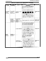
List of Tables
Table 3-1. Repair Tools . . . . . . . . . . . . . . . . . . . . . . . . . . . . . . . . . . . . . . . . . . . 3-1
Table 3-2. Measuring Instruments . . . . . . . . . . . . . . . . . . . . . . . . . . . . . . . . . . . 3-1
Disassembly and Assembly
LX-105O+ Service Manual
3.1 GENERAL REPAIR INFORMATION
This chapter describes the procedures for removin~ replacins and adjusting the main components
of the LX-105O+.
Prior to beginning any of these procedures, be certain that the AC power cord is
disconnected.
To help prevent hands jiotn being cut by the printer mechanism or sharp plate edges, wear
gloves when performing these procedures.
The printer mechanism, boards, and other parts are sometimes held in place with plastic
clips rather than screws. Be carefil not to damage these clips when removing them.
Tables 3-1 and 3-2 list tools and measuring instruments recommended for carrying out disassembly
and repair.
Table 3-1. Repair Tools
Description
Part No.
Round-nose pliers
B7404OO1OO
Nipper
6740500100
I
Tweezers
B641OOO1OO
Electric soldering iron
B7402OO1OO
E-ring holder #2.5
6740800400
E-ring holder #5
6740800700
PhiliDs screwdriver No. 2
I
Screwdriver No. O
1
Thickness gauge set (#F518)
6743800200
6743800300
B776702201
I
I
I
I
Table 3-2. Measuring Instruments
Description
Oscilloscope
Muttimeter
I
I
I
To ensure optimal performance of the printer, be sure, following reassembly and adjustment, to
lubricate, apply adhesive, clean, and maintain, according to the procedures described in Chapter 6.
Rev. A
3-1
LX-105O+ Service Manual
Disassembly and Assembly
3.2 DISASSEMBLY AND ASSEMBLY
This section details the disassembly procedures for the LX-105O+. As a rule, reassembly is
performed by simply reversing the procedures; a number of special notes, however, are provided
under the heading “Notes for Reassembly.” When a disassembly or reassembly procedure requires
that an adjustment be performed, the adjustment is described under the heading, “Required
Adjustment.” Be sure to perform these adjustments as indicated.
Be sure that you have read Section 4.1, “General Repair Information,” before performing
disassembly.
Be sure that paper and ribbon cartridge are removed before disassembly.
The disassembly procedure detailed below is in the following sequence: (1) removal of the
printhead, (2) removal of the casings, (3) removal of the circuit boards, (4) removal of the printer
mechanism unit, and (5) disassembly of the printer mechanism.
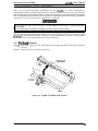
3.2.1 Printhead Removal
[Step 1] Remove the printer cover, and confirm that paper and ribbon cartridge have been
removed.
[Step 2] Open the cover of the paper tension unit.
paper TensIon
/
[
I
“
[
Prlnthead
I
Pli4en
Figure 3-1. Paper Tension Unit Cover
3-2
Rev. A
LX-105O+ Service Manual
Disassembly and Assembly
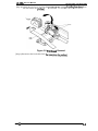
[Step 3] Unlock the two levers securing the printhead to thecarnage bypulhngthemdown. Then
lift and remove the printhead.
P
Levers
Figure 3-2. Printhead Removal
[Step 4] Disconnect the head cable from theconnector ontheprinthead.
Rev. A
3-3
LX-105O+ Service Manual
Disassembly and Assembly
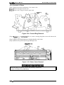
3.2.2 Removal of Casing
This section details the procedure for removing the upper casing and the control panel.
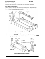
3.2.2.1 Upper Casing Removal
[Step 1] Remove the sheet guide unit, printer cover, paper tension unit, and paper feed knob.
[Step 2] Pull in the two notches securing the push tractor to the printer mechanism, and remove
the push tractor from the printer mechanism.
Figure 3-3. Push Tractor Removal
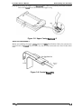
[Step 3] Remove the two C.B.B-tite (M4 x 25) screws securing the upper case.
[Step 4] Insert a standard screwdriver into each of the two holes at the front of the upper msing,
and gently push (See figure 3-4) to unlock the notches.
u
The notch can be
unlocked by pushing
it in the direction
shain by the
arrow using
the screwdriver
\~
\
[“<l
I
.1
CBB(M4 X 25)
6
Upper
Case
Notch
c“’”’ ’”
v
Lower
Case
Guide
w
Figure 3-4. Upper Casing Removal -1
3-4
Rev. A
Disassembly and Assembly
LX-105O+ Service Manual
[Step 5] While lifting the upper casing, discomect the cable of the control panel from connector
CN3 on the TAMA board. Then remove the upper casing.
Figure 3-5. Upper Casing Removai -2
NOTE FOR REASSEMBLY:
Before reassembling the upper casin& prepare the FFC (Flat Flexible Cable) that connects the
Control Panel and TAMA board in such a way that it can be connected to the Panel Cable Sailed
Plate.
Control
Panel
Figure 3-6. Control Panei FFC
Rev. A
3-5
Disassembly and Assembly
LX-105O+ Service Manual
3.2.2.2 Control Panel Removal
[Step 1] Remove the upper casing (as described in the previous section).
[step 2] Turn the upper casing over, push in the two notches on the casing that are securing the
control panel to it, and remove the control panel.
anel
Figure 3-7. Control Panel Removal
3-6
Rev. A
Disassembly and Assembly
LX-105O+ Service Manual
3.2.3 Removal of Circuit Boards
This section describes the procedure for removing the TAMA Board and the TA-a filter unit.
3.2.3.1 TAMA Board Removal
[Step 1] Remove the upper casing (See section 3.2.2.1). The following connectors on the TAMA
—board, which are connecting it to external components, should be disconnected: CN4,
CN5, CN6, CN7, CN8 FFC (Flexible Flat Cable), and CN9.
Do not pull roughly on the connectors, or you may damage the board. Remove them by
pulling gently while at the same time holding the board.
[Step 2] Remove the two C.B.Btite (P2) (M3 x 6) screws, the C.B.S-tite (0) (M3 x 8) screw, and
grand rink which are securing the TAMAboard to the base plate and the lower casing.
[Step 3] Loosen the four bent tabs on the lower casing which are securing it to the TAMA board.
Then remove the TAMA board.
CBS(0)(M3X8)
~TAMA
8oard
CN9
CN8
CN7
I
CN6
I
CN5
\
CN4
Figure 3-8. TAMA Board Removal
Be carefil not to bend the tabs toofar. Also, when pushing the tabs, be careful not to break
them or to cause damage to components on the TM board.
When the TM board is replaced, perform the following adjustment.
Section 4.2 BI-DIRECTIONAL PRIN7TNG ALIGNMENTADJUSZ7WENT
Rev. A
3-7
LX-1050+ Service Manual
Disassembly and Assembly
3.2.3.2 TA-a Filter Unit Removal
[Step 1] Remove the upper casing (See section 3.2.2.1).
[Step 2] Disconnect connector CN9 at the TAMA board. This comector comects the TA-a filter
unit.
[Step 3] Remove the C. B.(O) (M4 x 8) screw securing the frame ground wire.
[Step 4]
Remove the two C. B.B-tite (M4 x 12) screws and two C.B.(O) (M4 x 8) screws securing the
filter unit, and then remove the unit.
CB(0)(M4X8)
screw
/
I
CBB(M4X12)
~ Screw
I
II /
CBB(M4X12)
screw
CB(0)(M4X8)
Screw
C6(0~(M4x8)
screw
TAs ‘Fitter
Unit
Figure 3-9. TA-a Filter Unit Removal
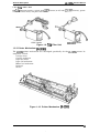
3.2.4 Removal of Printer Mechanism
This section describes the removal of printer mechanism.
[Step 1] Disconnect the cables from the following connectors on the TAMA board: CN4 (red),
CN5 (white), CN6 (black), and CN8 FFC (Flexible Flat Cable).
[Step 2] Remove the fore C. B.B-tite (M4 x 12) screws securing the printer mechanism to the lower
case.
[Step 3] Remove the printer mechanism.
II+M!
}=J
d LB-III
n
\
Figure 3-10. Printer Mechanism Removal
When the printer mechanism is replaced, perform the following adjustment.
Section 4.2 BI-DIREC~ONAL PRlN77NG ALIGNMENTADJUSTMENT
3-8
Rev. A
Disassembly and Assembly
LX-105O+ Service Manual
3.2.5 Disassembly of Printer Mechanism
This section details the removal of components from the printer mechanism.
3.2.5.1 Removal of Carriage Motor
[Step 1] Remove theprintermechanism (See section 3.2.4).
[Step 2] Disconnect the motor cable from the carriage motor.
[Step 3] Remove the belt tension spring EOO1 from the base frame.
[Step 4] Remove the timingbelt fromthebeltpulley.
[Step 5] Remove the carriage motor mounting plate together with the carriage motor.
I
Connector
—CR Motor
Frame
‘CR Motor
Helical
Spring
Figure 3-11. Carriage Motor Mounting Plate Removal
[Step 6] Remove the two C.B.S-tite (0) (M3 x 6) screws on the rear side of the carriage motor
mounting plate, which secure the carriage motor.
, CR Motor Frame
,
CBS(0) screw
(M3x6)
/
+
4
CR Motor
EM-142
EPM
260
o
CBS(0) Screw
0511
(M3x6)
~
+
Figure 3-12. Carraige Motor Removal
DDnlB&YuUltiNua :4K8ZSM:WIIBI
When the carriage motor is removed, perform the following adjustment.
Section 4.1.1 Carriage Motor Backlash Adjustment
4.2 BI-DHWCTIONAL. PRINTER ALIGNMENTADJUSTMENT
Rev. A
3-9
Disassembly and Assembly
LX-105O+ Service Manual
3.2.5.2 Removal of Home-Position Sensor
[Step 1] Remove the printer mechanism. (See section3.2. 4)
[Step 2] Turn the printer mechanism upside-down.
[Step 3] Push in the notch securing the home-position sensor, and remove the sensor from the
base frame.
Notch
HP
Sensor
Figure 3-13. Home-Position Sensor Removal
3-10
Rev. A
Disassembly and Assembly
LX-105O+ Service Manual
3.2.5.3 Removal of Platen
[Step 1] Remove the printer mechanism. (See section 3.2.4)
[Step2] Remove the paper tension unit.
[Step3] Remove the C-ring (6) from the plate shaft.
Crecent Ring
Figure 3-14. Cresent Ring Removal
[Step 4] Remove the two C.B.N.Stite (M3 x 6) screws securing the platen cover and remove the
platen cover.
[Step 5] Remove theshaftholderfrom therightsideofthe side frame.
[Step 6] Remove the platen bymovingit totheright side.
CB(N)S (M3x6)
Screws
f?
J
Figure 3-15. Platen Cover Removal
mn~umlum :wK@lDma31Dl
When the platen is replaced, perform the following adjustment.
Section 4.1.3 Platen Gap Adjustment
Rev. A
3-11
LX-105O+ Service Manual
Disassembly and Assembly
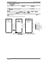
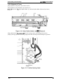
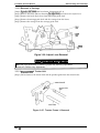
3.2.5.4 Separate of Frame
[Step 1] Remove the platen. (See section 3.2.5.3)
[Step 2] Remove the printhead. (See section 3.2.1)
[Step3] Remove the FFC, head cable holder (L), and head cable holder (R) from base frame.
Head Cable’ Hoder L
Head Cable Hoder R
Figure 3-16. Head Cable Holder and FFC Removal
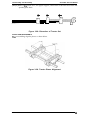
[Step 4] Disconnect themotor@ble from the carnage motor and thepaperfeed motor.
[Step 5] Change position of tension spring hook from normal position totemporary position.
~OOOHelical Spring
2
= Normal
Position
/
Temp{ary Position
Figure 3-17. Helical Spring Hook
3-12
Rev. A
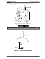
Disassembly and Assembly
LX-105O+ Service Manual
[Step 6] Push thetwonotches of the release lever outward. Remove the release lever.
\
Figure 3-18. Release Lever Removal
When the release lever is replaced, the markings should be analogously positioned.
Release Lever
}
L
o
Marking
f
.’
Figure 3-19. Release Lever Replacement
Rev. A
3-13
LX-105O+ Service Manual
Disassembly and Assembly
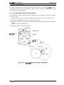
[Step 7] Separate
the tractor cancellation cum from paper feed lever cancellation shaft.
an
,Tractor
Disengage
Cam
-2iiB
\
Paw
Lever
Drive
Shaft
Separation of Tractor Diseugage Cam
[Step 8]
Turn the printer mechanism upside-down, and manually move the carriage unit until it is
at the cut-out section of the base frame. The joint of the carriage unit and timing belt
should be visible through the cut-out.
‘~1 ,;‘:=’
u
a
n
❑
❑
ilQ
D
❑
-E
~“m
00
no
cut-out
0
II
00
o
0
o
c1
0
El
II
ll~n
o
n
00
Base Frame
Figure 3-21. Bottom View of Printer Mechanism
3-14
Rev. A
Disassembly and Assembly
LX-105O+ Service Manual
[Step9] Remove the two C.B.S-tite. (0) (M3 x 6) screws which are securing the side frames to the
base frame, and remove the side frames. Separate side frames from base frame.
CBS(0) (M3~ 6) Screws
Figure 3-22. Separate of Frame
When the printer mechanism is separated, perform the following adjustment.
Section 4.1.3 Platen Gap Adjustment
3.2.5.5 Removal of Paper Feed Motor
[Step 1] Separate side frames from base frame. (Seesection3.2.5 .4)
[Step 2] Remove the two C.B.S-tite.(0) (M3 x6) screws securing the paper feed motor.
PF Motor
Figure 3-23. Paper Feed Motor Removal
When the paper feed motor is removed, petform the following adjustment.
Section 4.1.2 Paper Feed Motor Backlash Adjustment
Rev. A
3-15
LX-105O+ Service Manual
Disassembly and Assembly
3.2.5.6 Removal of Paper End Sensor
[Step 1] Separate side frames from base frame. (See section 3.2.5.4)
[Step 2] Loosen the two bends securing the paper end sensor to the paper guide at the back of the
printer.
[Step 3] Remove the paper end sensor.
Bends
Psper
Guide
PE
Sensor
r
/
Figure 3-24. Paper End Sensor Removal
3.2.5.7 Removal of Paper Guide Plate
[Step 1] Separate side frames from base frame. (See section 3.2.5.4)
[Step 2] Remove the paper guide plate spring from the base frame.
[Step 3] Remove the paper guide plate.
Paper
Guide
Plate
Springs
Springs
Figure 3-25. Paper Guide Plate Removal
3-16
Rev. A
Disassembly and Assembly
LX-105O+ Service Manual
3.2.5.8 Removal of Carriage
[Step 1] %paratesideframes from base frame. (Seesection3.2.5 .4)
[Step 2] Remove the HNO (M4) nut Securing theadjustlever, and remove the adjust lever.
[Step 3] Remove the head adjust lever from thecarriage guide shaft.
[Step 4] Remove thecarnageguide shaft and the carriage from the frame.
[Step 5] Remove the carnage from the carriage guide shaft.
O(M4)
Figure 3-26. Adjust Lever Removal
When the paper feed motor is removed, perform the following adjustment.
Section 4.1.3 Platen Gap Adjustment
3.2.5.9 Diaaaaembly of Tractor Unit
[Step 1] Pull and remove the tractor shaft and the sprocket guide from the tractor frame.
/7zkTrac’0’Frame(L’
Figure 3-27. Tractor Frame L Removal
Rev. A
3-17
LX-105O+ Service Manual
Disassembly and Assembly
[Step 2] Remove the tractor set L, the paper support, and tractor set R from the tractor and
sprocket guide shafts.
4-
T7
5-
Figure 3-28. Extraction of Tractor Set
NOTES FOR REASSEMBLY:
When reassembling, align the phases as shown below.
,-
/a
‘,.-’,
Figure 3-29. Tractor Phase Alignment
3-18
Rev. A
Chapter 4 Adjustments
Table of Contents
4-1
4.1 ADJUSTMENTS
4.1.1 Carriage Motor Backlash Adjustment . . . . . . . . . . . . . . . . . . . . . . . . . . . 4-1
4.1.2 Paper Feed Motor Backlash Adjustment. . . . . . . . . . . . . . . . . . . . . . . . . 4-2
4.1.3 Paten Gap Adjustment . . . . . . . . . . . . . . . . . . . . . . . . . . . . . . . . . . . . . . 4-3
4.2 61-DIRECTIONAL PRINTING ALIGNMENT ADJUSTMENT
4-5
List of Figures
Figure 4-1. Carriage Motor Backlash Adjustment . . . . . . . . . . . . . . . . . . . . . . . 4-1
Figure 4-2. Paper Feed Backlash Adjustment. . . . . . . . . . . . . . . . . . . . . . . . . . 4-2
Figure 4-3. Removal of Ribbon Mask . . . . . . . . . . . . . . . . . . . . . . . . . . . . . . . . 4-3
Figure 4-4. Head Adjust Lever B . . . . . . . . . . . . . . . . . . . . . . . . . . . . . . . . . . . . 4-3
Figure 4-5. Platen Gap Adjustment. . . . . . . . . . . . . . . . . . . . . . . . . . . . . . . . . . 4-4
Figure 4-6. Eccentric of Guide Shaft . . . . . . . . . . . . . . . . . . . . . . . . . . . . . . . . . 4-4
Figure 4-7. Paten Gap. . . . . . . . . . . . . . . . . . . . . . . . . . . . . . . . . . . . . . . . . . . . 4-4
Adjustments
LX-105O+ Service Manual
4.1 ADJUSTMENTS
section describes the adjustment procedures necessary when the LX-105O+ printer is
reassembled or when parts are reinstalled or replaced. These procedures are necessary to ensure
the correct operation of the printer.
This
4.1.1 Carriage Motor Backlash Adjustment
This adjustment is
position is shifted.
1.
required either when the carriage motor is replaced or when its mounting
Remove the carriage motor frame and carnage motor from base frame. (See section 3.2.5.1)
2. Loose the two CBS(0) (M3 x 6) screws on the carriage motor.
3. Manually rotate the carnage motor, and adjust the backlash between the pinion and the belt
pulley.
Allowable backlash: 0.05-0.15 mm
4. Tighten the screws on the carriage motor.
CR Motor Frame
CBS(0) SCreW
(M3x6)
CR Motor
CBS(0) Screw
(M3x6)
o “
P
/“
Belt Pulley
/
Pinion Gear
\\
\
‘ \
Figure 4-1. Carraige Motor Backlash Adjustment
Rev. A
4-1
LX-105O+ Service Manual
Adjustments
4.1.2 Paper Feed Motor Backlash Adjustment
This adjustment
is required either when the paper feed motor is replaced or when its mounting
position is shifted.
1. Separate side frames from base frame. (See section 3.2.5.4)
2. Loose the two CBS(0)(M3 x 6) screws on the paper feed motor.
3. Manually rotate the paper feed motor, and adjust the backlash between the pinion and the
appear feed reduction gear.
Allowable backlash: 0.05-0.20 mm
4. Tighten the screws on the paper feed motor.
PF Motor
\
~y)
/“
/ “0 -
“
\.
Pinion Gear
Paper Feed Reduction Gear
.-
,.
~ )“,
o
“
1’
)
0.05 -O.20mm
,,
/
“’==4 . .
/
0 /’
“’---d’
Figure 4-2. Paper Feed Motor Backlash Adjustment
4-2
Rev. A
Adjustments
LX-105O+ Service Manual
4.1.3 Platen Gap Adjustment
Following the removal of the carriage guide shaft or adjust lever, or if printing is abnormal, the gap
between the platen and the print head should be adjusted.
1. Remove the printer mechanism (See section 3.2.4),
2. Remove the printhead. Using tweezers, remove the ribbon mask. Remove the maskby pulling
it slightly forward, then lifting.
Figure 4-3. Removal of Ribbon Mask
3. Reinstall the printhead.
4. Set the release lever to the friction position.
5. Set the parallel adjust lever to the center position.
6. Manually move he carriage to column 126.
7. Lightly loosen the HMO(M4) nut securing the head adjust lever.
m
Figure 4-4. Head Adjust Lever B
Rev. A
44
LX-105O+ Service Manual
Adjustments
8. insert the blade of a screwdriver into the countersink of carnage guide shaft.
< Countersink>
Large
Small
\
==
\/’”
r--I
I
I
Carriage G;ide Shaft B
I
Figure 4-5. Platen Gap Adjustment
9. Adjust the platen gap using a thickness gauge, while rotating carnage guide shaft in the
direction of the arrow in figure.
Gap value: 0.44 mm gauge is inserted.
0.47 mm gauge is not inserted.
I
,/ ~111]
/;!1’ ,,,;
0.4!5mm
\
-
/
Platen
Carriage Guide Shaft
‘
Printhead
//
Screw
up
a>b
Figure 4-6. Eccentric of Guide Shaft
Figure 4-7. Platen Gap
10. Set the head adjust lever at the 2nd position in step 9, and tighten the HNO(M4) nut.
11. Manually move the carriage to column 10.
12. Using the thickness gauge, parallel adjust lever so that the platen gap matches the specified
value.
13. Move the carriage to the 126 column, and measure the gap value again to confirm that the gap
value is correct.
14. Remove the printhead from the carriage and set the ribbon mask, then reinstall the printhead
on the carriage.
4-4
Rev. A
LX-105O+ Service Manual
Adjustments
4.2 61-DIRECTIONAL PRINTING ALIGNMENT ADJUSTMENT
The bi-directional printing alignment adjustment is required when the printer mechanism or the
main board is replaced. By performing this adjustment, a compensation value is determined for the
mechanical control as to compensate the deviation of print position, which may be caused by the
different print speeds due to the tolerance of the mechanical components, and the deviation of
print timing between odd-numbered lines and even-numbered lines in bi-directional printing. The
printer stores the compensation data in the EEPROM on the main board (TAMA), and referring to
this data when the bi-directional printing is performed.
1.
3.
Set continuous paper to the tractor unit of the printer.
Connect the PC to the printer and turn the both units on.
Execute BASIC on the PC and start the adjustment program “SHASTAWP.BAS”.
4.
Follow the instruction displayed on the monitor, and press ENTER key to start the adjustment.
5.
The printer pMts the draft mode check pattern with a sample compensation value.
6.
Check the printed draft mode sample pattern, and if the character” 1“ is not vertically aligned
in both mid-numbered lines and even-numbered line, enter the compensation value in the
range from -16 to +16, from the keyboard.
■ Positive compensation value:
Shift 2nd line to LEFT
H Negative compensation value: Shift 2nd line to RIGHT
7.
The printer print the daft mode sample pattern with the selected compensation value for
confirmation. If the alignment is good, press “Y” to NLQ mode adjustment.
The printer printing NLQ mode sample pattern. The procedure of NLQ mode adjustment is
same as procedure of draft mode.
If the alignment is good, press “Y” to finish the adjustment.
2.
8.
9.
10, Turn the printer off.
Because the compensation value specified within this program is not valid until the printer is
turned off, turn the printer off immediately after you have finish the adjustment.
Rev. A
4-s
Chapter 5 Troubleshooting
Table of Contents
5.1 OVERVIEW
5-1
5.2 SELF-DIAGNOSTIC FUNCTION
5-2
5-2
5.3 TROUBLESHOOTING
5.3.1 Troubleshooting of Abnormal Operation . . . . . . . . . . . . . . . . . . . . . . . . . 5-3
5.3.2 Unit Repair - TAMA Main Control Board . . . . . . . . . . . . . . . . . . . . . . . . 5-12
List of Tables
Table 5-1. Motor Resistance . . . . . . . . . . . . . . . . . . . . . . . . . . . . . . . . . . . . . . . 5-1
Table 5-2. Sensor Status. . . . . . . . . . . . . . . . . . . . . . . . . . . . . . . . . . . . . . . . . . 5-1
Table 5-3. Error Codes . . . . . . . . . . . . . . . . . . . . . . . . . . . . . . . . . . . . . . . . . . . 5-2
Table 5-4. Symptoms and Problems. . . . . . . . . . . . . . . . . . . . . . . . . . . . . . . . . 5-3
Table 5-5. The Printer does Not Operate at All . . . . . . . . . . . . . . . . . . . . . . . . . 5-4
Table 5-6. The LEDs do Not Operate at All. . . . . . . . . . . . . . . . . . . . . . . . . . . . 5-4
Table 5-7. The Buttons do Not Operate at All . . . . . . . . . . . . . . . . . . . . . . . . . . 5-4
Table 5-8. Carriage Error Displayed . . . . . . . . . . . . . . . . . . . . . . . . . . . . . . . . . 5-5
Table 5-9. Paper is Not Fed (1). . . . . . . . . . . . . . . . . . . . . . . . . . . . . . . . . . . . . 5-6
Table 5-10. Paper is Not Fed (2). . . . . . . . . . . . . . . . . . . . . . . . . . . . . . . . . . . . 5-7
Table 5-11. Paper Out Displayed . . . . . . . . . . . . . . . . . . . . . . . . . . . . . . . . . . . 5-7
Table 5-12. Abnormal Voltage Displayed . . . . . . . . . . . . . . . . . . . . . . . . . . . . . 5-8
Table 5-13. Incorrect SRAM Displayed . . . . . . . . . . . . . . . . . . . . . . . . . . . . . . . 5-8
Table 5-14. Incorrect RAM Inside CPU Displayed. . . . . . . . . . . . . . . . . . . . . . . 5-8
Table 5-15. Self-test is Abnormal . . . . . . . . . . . . . . . . . . . . . . . . . . . . . . . . . . . 5-8
Table 5-16. Self-test Printout has Poor Quality (1) . . . . . . . . . . . . . . . . . . . . . . 5-9
Table 5-17. Self-test Printout has Poor Quality (2) . . . . . . . . . . . . . . . . . . . . . 5-10
Table 5-18. Abnormal Printing in On-line Mode (1) . . . . . . . . . . . . . . . . . . . . . 5-10
Table 5-19. Abnormal Printing in On-line Mode (2) . . . . . . . . . . . . . . . . . . . . . 5-11
Table 5-20. Abnormal Printing in On-line Mode (3) . . . . . . . . . . . . . . . . . . . . . 5-11
Table 5-21. Repair of the TAMA Board. . . . . . . . . . . . . . . . . . . . . . . . . . . . . . 5-12
Troubleshooting
LX-105O+ Service Manual
5.1 OVERVIEW
Troubleshooting most other serial impact dot matrix printers is difficult to perform, since there
may be wide variety of problems. Therefore, the LX-105O+ have a sophisticated, built-in
selfdiagnostic function that reduces troubleshooting time by identifying failed parts or
components.
The following tables and figure provide troubleshooting information.
Table 5-1. Motor Resistance
Motor
Resistance
Remark
CR Motor
11.0 Q *10 Q / Phase
At25“C
PF Motor
40.0 Q * 7?40 / Phase
At25‘C
Table 5-2. Sensor Status
Point
Sensor
H (5V)
PE Sensor
CN6 / Pin 1
HP Sensor
CN7 / Pin 1
Release Sensor
CN4 / Pin 1
Status
Signal Level
Paper exist
L (GND)
No paper (Paper end)
H (5V)
Out of home position
L (GND)
H (5V)
L (GND)
At home position
Friction feed
Release/Tractor feed
o
#l
o #2
Printhead
o #3
o #4
O
.8
0
# 9
( Wire assignment)
Coil Resistance:
19.2 & 1.90 at 25-C
(8etween each dot wira and common.)
#’1 #’3
j#12 #14 #16
( Terminal assignment)
Figure 5-1. Printhead Resistance
Rev. A
5-1
LX-1050+ Service Manual
Troubleshooting
5.2 SELF-DIAGNOSTIC FUNCTION
the selfdiagnostic function, in which the controller automatically checks the
operating conditions of each component. If any abnormality is detected, the printer displays an
error message by beep sound. Table 5-3 lists the messages that tell you if service maintenance is
required.
This section describes
Table 5-3. Error Codes
Error
Carriaae trouble
Buzzer
I Bee~s 6 times, pausing after 3rd beep
Paper out
Beeps 20 times, pausing briefly after 4 beeps
Abnormal voltage
Beeps 8 times, pausing after every beep
Incorrect SRAM
Beeps 8 times, pausing briefly after 2 beeps
Incorrect RAM inside CPU
5-2
I
I
I Beeps indefinitely until power OFF
Rev. A
Troubleshooting
LX-105O+ Servjce Manual
5.3 TROUBLESHOOTING
This section describes the troubleshooting of abnormal operations and circuit board unit repair.
5.3.1 Troubleshooting of Abnormal Operation
This section describes how to detect malfunctions, how to determine the cause, and what actions to
take for various types of malfunctions. Each paragraph refers you to a detailed troubleshooting
table.
Table 5-4. Symptoms and Problems
Printer Condition
Symptom
The printer does not operate at all.
Printer mechanism does not starl
initialize, when power on.
The LEDs on control panel does not
oDerate at all.
The printer mechanism start initialized,
but LEDs does not operate.
The buttons on control panel does not
operate
The printer does not change state, when
push the button.
5-7
Carriage error displayed
The printer display carriage error, when
power on.
5-8
Paper is not fed
The paper is not fed from tractor.
5-9
The paper is not fed from manual feed
slot.
5-1o
Paper out displayed
Abnormal voltage displayed
Incorrect SRAM disdaved
Incorrect RAM inside CPU displayed
5-5
I
5-6
\ The paper is fed, but paper out displayed I
5-11
I
I
I The printer display abnormal voltage.
5-12
,
1
ITheprinterdisplawd incorrect SRAM. I 5 - 1 3
The printer display incorrect RAM inside
5-14
CPU.
Self test abnormal
The carriage is moved, but the printhead
does not print.
Self test printout has poor quality
Dot missing
5-15
5-16
I
I Line spacing is bad
Abnormal print in on line mode
Bi-directional printing position is abnormal
The printer does not print.
I Data from the host is incorrectly
Rev. A
1
5-17
5-18
I
5-19
5-20
5-3
LX-105O+ Service Manual
Troubleshooting
Table 5-5. The Printer does Not Operate at All
Checkpoint
Finding
Solution
Is connector CN9 on the
TAMA board disconnected?
Yes
Connect CN9 on
TAMA board
Is the fuse F1 on the TA-a
filter unit blown?
Yes
Replace the fuse
F1 .
Step
Cause
~
The TA-a filter unit maybe
dead.
I
The TAMA board maybe
bead.
With the power on, are there
output of 26 VAC between
two red wires and 12 VAC
between two blue wire for
CN1 on the TA-a filter unit.
4
No
Replace the
TA-a filter unit.
—
Replace the
TAMA boafd
Table 5-6. The LEDs do Not Operate at All
Cause
Step
Checkpoint
Finding
Solution
Connector CN3 on the TAMA
board may be disconnected.
,
Is connector CN3 on the
TAMA board disconnected?
Yes
Connect CN3 on
the TAMA board.
Control panel may be dead.
2
—
—
Replace the
control panel.
The TAMA board maybe
dead.
3
—
—
Replace the
TAMA board.
Table 5-7. The Buttons do Not Operate at All
Cause
Step
Checkpoint
Finding
Solution
Connector CN3 on the TAMA
board may be disconnected.
,
Is connector CN3 on the
TAMA board disconnected?
Yes
Connect CN3 on
the TAMA board.
Control panel may be dead.
2
—
—
Replace the
control panel.
The TAMA board maybe
dead.
3
—
—
Replace the
TAMA board.
54
Rev. A
Troubleshooting
LX-105O+ Service Manual
Table 5-8. Carriage Error Displayed
Cause
Step
Checkpoint
Finding
Solution
The carriage
mechanism is bad.
1
Turn the printer off and try to move
the carriage manually. Does the
carriage move smoothly?
No
Check the
carriage
mechanism, and
replace or
reassembly the
bad patiS.
The HP sensor is dead.
2
Does the carriage move and clash
to right or left frame before error
displayed?
Yes
Replace the HP
sensor.
Disconnect CN5 on the TAMA
board and check the coil resistance
between: pin 6 and pin 4; pin 2 and
pin 4; pin 5 and pin 3; pin 1 and pin
3 (4 points total) on the
disconnected cable side using a
muitimeter.
Pin 6- Pin 4
Pin 2- Pin 4
Pin 5- Pin 3
Pin 1- Pin 3
Are the resistances of all four
points approximately 11 ohms?
No
Replace the
carrfage motor.
If any coil is shorted, check the
carriage motor drive circuit using
the following procedure:
1. Set the multimeter to
resistance check mode.
2. Place the (-) terminal of the
multimeter on pins 1, 2, 5, 6 of
connector CN5 on the TAMA
board.
3. Place the (+) terminal on pin 2 of
connector CN7 on the TAMA
board. (GND)
With power off, does the
multimeter detect “00” ?
No
Replace the
carriage motor
with TAMA board.
The carriage motor is
dead.
The TAMA boards may
be dead.
Rev. A
s
d
Replace the
TAMA board.
5-5
LX-105O+ Service Manual
Troubleshooting
Table 5-9. Paper is Not Fed (1)
Cause
Checkpoint
Step
The paper end sensor
Does the sensor toggle?
may be dead.
‘
(Check with multimeter)
The release sensor
may be dead.
2
Does the sensor toggle?
(Check with multimeter)
Finding
No
No
Solution
Replace the
paper end
sensor.
Replace the
release sensor.
Disconnect CN5 on the TAMA
board and cheek the coil resistance
between: pin 12 and pin 10; pin 8
and pin 10; pin 11 and pin 9; pin 7
and pin 9 (4 points total) on the
disconnected cable side using a
multimeter.
Pin 12- Pin 10
Pin 8- Pin 10
Pin 11- Pin 9
Pin 7- Pin 9
Are the resistances of all four
points approximately 40 ohms?
The paper feed motor
may be dead.
No
Replace the
paper feed motor.
~
If any coil is shorted, check the
paper feed motor drive circuit using
the following procedure:
1. Set the multimeterto
resistance check mode.
2. Place the (-) terminal of the
multimeter on pins 7, 8, 11, 12 of
connector CN5 on the TAMA
board.
3. Place the (+) terminal on pin 2 of
connector CN7 on the TAMA
board. (GND)
N.
Replace the
paper feed motor
with TAMA board.
With power off, does the
muitimeter detect “00” ?
The paper path may be
bad.
5-6
~
—
—
Reassemble the
paper path.
Rev. A
Troubleshooting
LX-105O+ Service Manual
Table 5-10. Paper is Not Fed (2)
Checkpoint
Cause
Finding
Solution
The paper end sensor
may be dead.
1
Does the sensor toggle?
(Check with multimeter)
No
Replace the
paper end
sensor.
The release sensor
may be dead.
2
Does the sensor toggle?
(Check with multimeter)
No
Replace the
release sensor.
Disconnect CN5 on the TAMA
board and check the coil resistance
between: pin 12 and pin 10; pin 8
and pin 10; pin 11 and pin 9; pin 7
and pin 9 (4 points total) on the
disconnected cable side using a
muitimeter.
Pin 12- Pin 10
Pin 8- Pin 10
Pin 11- Pin 9
Pin 7- Pin 9
Are the resistances of all four
points approximately 40 ohms?
No
Replace the
paper feed motor.
If any coil is shorted, check the
paper feed motor drive circuit using
the following procedure:
1. Set the multimeter to
resistance check mode.
2. Place the (-) terminal of the
multimeter on pins 7, 8, 12 of
connector CN5 on the TAMA
board.
3. Place the (+) terminal on pin 2 of
connector CN7 on the TAMA
board. (GND)
With power off, does the
multimeter detect “CO” ?
No
Replace the
paper feed motor
with TAMA board.
The paper feed motor
may be dead.
The paper path may be
bad.
3
4
Reassemble the
paper path.
—
Table 5-11. Paper Out Displayed
Cause
The paper end sensor
is dead.
Rev. A
Step
1
Checkpoint
—
Finding
—
Solution
Replace the
paper end
sensor.
5-7
LX-105O+ Service Manual
Troubleshooting
Table 5-12. Abnormal Voltage Displayed
Step
Cause
Checkpoint
The CR motor, PF
motor or printhead coil
is short.
1
Connector CN5 and CN8
disconnect, and power on.
Does printer not display abnormal
voltage?
The TAMA board may
be bad.
2
—
Finding
Solution
Yes
Replace CR
motor, PF motor
or printhead.
—
Replace TAMA
board.
Table 5-13. Incorrect SRAM Displayed
Step
Cause
The TAMA board may
1
Checkpoint
Finding
—
—
be bad.
Solution
Replace the
TAMA board.
Table 5-14. Incorrect RAM Inside CPU Displayed
Cause
The TAMA baord WY
be bad.
I Step I
1
Checkpoint
Finding
—
—
Solution
Replace the
TAMA board.
Table 5-15. Self-test is Abnormal
Cause
Step
Checkpoint
Finding
Solution
Connectors on the
printhead maybe
disconnected.
1
Is connectors on the printhead
disconnected?
Yes
Conneot
connector on the
printhead.
Ink ribbon may be bad.
3
Is printing OK after ink ribbon
replacement?
Yes
Replace the ink
ribbon.
Printhead maybe bad.
5
—
—
Replace the
printhead.
5-s
Rev. A
Troubleshooting
LX-105O+ Service Manual
Table 5-16. Self-test Printout has Poor Quality (1)
Cause
The printhead wire
may be broken.
Step
1
Checkpoint
Check the printhead.
Are wires OK?
Check the printhead coil resistance
by multirneter.
.(refer to figure 5-1)
Are coils short or open?
Finding
Solution
No
Replace the
printhead.
Yes
Replace the
printhead.
No
Replace the
paper feed motor
with TAMA board.
If any coil is shorted, check the
printhead drive circuit using the
following procedure:
The printhead coil
short or open.
Rev. A
2
1. Set the multimeter to
resistance check mode.
2. Place the (-) terminal of the
muitimeter on collector of
printhead drive transistor on the
TAMA board.
3. Place the (+) terminal on emitter
of transistor on the TAMA board.
(GND)
With power off, does the
multimeter detect “00” ?
5-9
LX-105O+ Service Manual
Troubleshooting
Table 5-17. Self-test Printout has Poor Quality (2)
Cause
Step
Paper feed mechanism
,
may be bad.
Checkpoint
Check the paper feed mechanism
gears and rollers.
Are there OK?
Finding
Solution
No
Replace or
reassemble
gears and rollers.
No
Replace the
paper feed motor.
Disconnect CN5 on the TAMA
board and check the coil resistance
between: pin 12 and pin 10; pin 8
and pin 10; pin 11 and pin 9; pin 7
and pin 9 (4 points total) on the
disconnected cable side using a
multimeter.
Pin 12- Pin 10
Pin 8- Pin 10
Pin 11- Pin 9
Pin 7- Pin 9
Are the resistances of all four
points approximately 40 ohms?
The paper feed motor
may be dead.
The paper path may be
bad.
z
If any coil is shorted, check the
paper feed motor drive circuit using
the following procedure:
1. Set the multimeter to
resistance check mode.
2. Place the (-) terminal of the
multimeter on pins 7, 8, 11, 12 of
connector CN5 on the TAMA
board.
3. Place the (+) terminal on pin 2 of
connector CN7 on the TAMA
board. (GND)
With power off, does the
multimeter detect “~” ?
s
N.
—
—
Replace the
paper feed motor
with TAMA board.
Reassemble the
paper path.
Table 5-18. Abnormal Printing in On-line Mode (1)
Cause
The bi-directional
printing value may be
bad.
5-10
Step
1
Checkpoint
—
Finding
Solution
—
Adjust the
bi-directional
printing position.
(Refer to chapter
4)
Rev. A
Troubleshooting
LX-105O+ Service Manual
Table 5-19. Abnormal Printing in On-line Mode (2)
Finding
Solution
Is it OK?
No
Set the software
settings.
Is it OK?
No
Set the dip
switch settings.
Step
Cause
Checkpoint
Software setting may
be bad.
,
Dip switch settings of
printer may be bad.
~
Interface cable may be
bad.
~
Change the interface cable.
Does it print OK?
No
Replace the
intetface cable.
The TAMA board may
be bad.
~
—
—
Replace the
TAMA board.
Table 5-20. Abnormal Printing in On-1ine Mode (3)
Cause
Checkpoint
Step
Finding
Solution
Software setting may
be bad.
,
Is it OK?
No
Set the software
settings.
Dip switch settings of
printer may be bad.
*
Is it OK?
No
Set the dip
switch settings.
Interface cable may be
bad.
~
Change the interface cable.
Does it print OK?
No
Replace the
interface cable.
The TAMA board may
be bad.
~
—
—
Replace the
TAMA board.
Rev. A
5-11
LX-105O+ Service Manual
Troubleshooting
5.3.2 Unit Repair - TAMA Main Control Board
This section describes the problems related to the main control board (TAMA). The table below
provides various symptoms, likely causes, and checkpoints. me checkpoints refer to waveforms,
resistance, and other values to be checked to evaluate the operation of each component.
Table 5-21. Repair of the TAMA Board
Symptom
Condition
Cause
Checkpoint
Solution
M IC 3A, check the input waveform
It pin 5.
IC 3A is defective
Replace IC 3A.
IC 3Aor
transistor Q1
(Q2) is defective.
Replace 2C 3A
or Q1 (Q2).
SRI or transistor
Q6 is defective.
Replace SRI
or Q6.
The printer
The +24V is
~oes not
jead.
>perate at all.
The +5V is
~ead.
5-12
Rev. A
Troubleshooting
LX-105O+ Service Manual
Table 5-21. Repair of the TAMA Board (Continued)
Symptom
Condition
Checkpoint
cause
Solution
Oheck the voltage waveforms at the
E24V and for the RESET signal.
rhe reset circuit
s not operating.
+eplace Q5.
Selection of
rhe printer
The CPU is
mntrol ROM is
joes not
not operating. ~bnormal.
>perate at all.
7AM is defective
3eplace IC 3C.
—
?eplace IC 3D.
check for oscillator signal at either
~in 31 or pin 32 of the CPU
rhe CPU is
jefective
~eplace
LX-105O+ Service Manual
Troubleshooting
Table 5-21. Repair of the TAMA Board (Continued)
e..-- +A -
!5-14
Pfinr4itinn
Cause
Check~oint
Solution
Rev. A
LX-105O+ Service Manual
Troubleshooting
Table 5-21. Repair of the TAMA Board (Continued)
Rev. A
5-15
Chapter 6
Maintenance
Table of Contents
6-1
6.1 MAINTENANCE
6.1.1 Preventive Maintenance . . . . . . . . . . . . . . . . . . . . . . . . . . . . . . . . . . . . . 6-1
6.1.2 Lubrication and Adhesive Application . . . . . . . . . . . . . . . . . . . . . . . . . . . 6-1
List of Figures
Figure 6-1. Correct Adhesive Application . . . . . . . . . . . . . . . . . . . . . . . . . . . . . 6-2
Figure 6-2. Lubrication Points . . . . . . . . . . . . . . . . . . . . . . . . . . . . . . . . . . . . . . 6-3
List of Tables
Table 6-1. Lubrication andAdhesive . . . . . . . . . . . . . . . . . . . . . . . . . . . . . . . . . 6-1
Table 6-2. Lubrication Points . . . . . . . . . . . . . . . . . . . . . . . . . . . . . . . . . . . . . . . 6-2
Table 6-3. Adhesive Application Points . . . . . . . . . . . . . . . . . . . . . . . . . . . . . . . 6-2
Maintenance
LX-105O+ Service Manual
6.1 MAINTENANCE
Proper maintenance assures optimal and long-term printer perforrnance and minimizes the
occurrence of malfunctions.
Be sure to disconnect the printmfiom the power supply before maintenance.
Do not apply thinner, trichloroethylene, or ketone-based solvents to any of the printer’s
plastic components.
6.1.1 Preventive Maintenance
The case exterior should be regularly cleaned with alcohol. Occasionally vacuum clean the interior
of the mechanism to remove accumulated dirt, dust, and paper particles.
After the unit has been cleaned, check that it is adequately lubricated (refer to Section 6.2, below).
Before returning the printer to the customer, inspect the springs, paper-feed rollers, and the basic
operation of the unit.
6.1.2 Lubrication and Adhesive Application
EPSON recommends lubrication at the points illustrated in Figure 6-2. Table 6-2 provides a list of
these points, and the recommended lubricant to be used for each. The lubricants--EPSON O-2,
EPSON G-26, and EPSON G-37--have all been thoroughly tested and fully meet the needs of this
printer. (Table 6-1 lists details of these lubricants.)
Before applying any lubricant, make sure that the part to be lubricated is clean. Do not apply excess
lubrication, as this can potentially cause darnage.
Following its disassembly or replacement, adhesive must be applied to the part indicated in Table
6-3. EPSON recommends application of Neji lock #2 (G) adhesive to the point illustrated in Figure
6-1. When applying the adhesive, be careful that no excess overflows onto nearby parts.
Table 6-1. Lubrication and Adhesive
Name
Type
Capacity
Availability
Parts No.
Oil
o-2
40 cc
E
B7102OOOO1
Grease
G26
40 gm
E
B702600001
Grease
G37
40 gm
E
B703700001
Adhesive
Neji lock #2 (G)
40 gm
E
B730200200
E: EPSON-exclusive product
Rev. A
s-1
LX-105O+ Service Manual
Maintenance
Table 6-2. Lubrication Points
Lubrication Points
Ref. No.
Lubricant
(1)
Contact portion of paper feed lever drive shaft and paper feed lever
G-26
(2)
Contact portion of paper feed lever drive shaft and base frame
G-26
(3)
Oil pad
o-2
(4)
Contact portion of release lever and paper feed lever drive shaft
G-26
(5)
Contact portion of adjust lever and side frame left
G-26
(6)
Contact portion of adjust lever and side frame left
G-26
(7)
Contact portion of belt pulley and ribbon gear
G-26
(8)
Contact portion of carriage and carriage guide plate
G-26
(9)
Contact portion of tractor disengage cam and gear
G-26
(lo)
Gear portion of the ribbon gear
G-26
(11)
Shall which sets the ribbon gears
G-26
(12)
Paper feed roller shaft
G37
Note: Lubrication is necessaty when assembling.
Table 6-3. Adhesive Application Points
Ref. No.
Adhesive Application Points
No. of Points
(21)
Where the timing belt engages the carriage
1
(22)
Contact portion of side frame and paper guide
2
<To Timing Belt>
Figure 6-1. Correct Adhesive Application
6-2
Rev. A
Maintenance
LX-105O+ Service Manual
Figure 6-2. Lubrication Points
Rev. A
6-3
Appendix
Table of Contents
A.1 CONNECTOR SUMMARY
A-1
A.2 CIRCUIT DIAGRAM
A-5
A.3 CIRCUIT BOARD COMPONENT LAYOUT
A-8
A.4 EXPLODED DIAGRAM
A-9
List of Figures
Figure
Figure
Figure
Figure
Figure
Figure
Figure
A-1.
A-2.
A-3.
A-4.
A-5.
A-6.
A-7.
Interconnection of Major Components . . . . . . . . . . . . . . . . . . . . . . A-1
TAMA Main Control Board Circuit Diagram . . . . . . . . . . . . . . . . . . A-5
TA-a Filter Unit Circuit Diagram . . . . . . . . . . . . . . . . . . . . . . . . . . . A-7
Control Panel Circuit Diagram. . . . . . . . . . . . . . . . . . . . . . . . . . . . . A-7
TAMA Main Control Board Component Layout. . . . . . . . . . . . . . . . A-8
LX-1050+ Exploded Diagram . . . . . . . . . . . . . . . . . . . . . . . . . . . . . A-9
Printer Mechanism Exploded Diagram . . . . . . . . . . . . . . . . . . . . . A-10
List of Tables
Table A-1.
Table A-2.
Table A-3.
Table A-4.
Table A-5.
Table A-6.
Table A-7.
Table A-8.
Table A-9.
Connector
Connector
Connector
Connector
Connector
Connector
Connector
Connector
Connector
Summary . . . . . . . . . . . . . . . . . . . . . . . . . . . . . . . . . . . . A-2
Pin Assignment - CN2 . . . . . . . . . . . . . . . . . . . . . . . . . . A-3
Pin Assignment - CN3 . . . . . . . . . . . . . . . . . . . . . . . . . . A-3
Pin Assignment - CN4 . . . . . . . . . . . . . . . . . . . . . . . . . . A-3
Pin Assignment - CN5 . . . . . . . . . . . . . . . . . . . . . . . . . . A-4
Pin Assignment - CN6 . . . . . . . . . . . . . . . . . . . . . . . . . . A-4
Pin Assignment - CN7 . . . . . . . . . . . . . . . . . . . . . . . . . . A-4
Pin Assignment - CN8 . . . . . . . . . . . . . . . . . . . . . . . . . . A-4
Pin Assignment - CN9 . . . . . . . . . . . . . . . . . . . . . . . . . . A-4
Appendix
LX-105O+ Service Manual
A.1 CONNECTOR SUMMARY
Figure below shows the intercomection between the major components of the LX-105O+.
TAPNL-W
Contrgrr~anel
Model 3D60 Printer Mechanism
Release
I I
;; Inn::;
A
PE
II
HOME HEAD
II 4>
1
I
I
I
I
I
I
I
I
I
I
I
I
_l
-- . ------- L ---------t HOST COMPUTER 1
Figure A-1. Interconnection of Major Components
Rev. A
A-1
LX-105O+ Service Manual
Appendix
Table A-1. Connector Summary
Pins
Description
Connector
Reference
TAMA Main Control Board
I CN1 I
Parallel
interface
CN2
Optional interface board connector
CN3
Control panel
10 pin
Table A-3
CN4
Release lever
2 pin
Table A-4
CN5
CR motor and PF motor
12 pin
Table A-5
CN6
PE sensor
2 pin
Table A-6
! CN7 I Home Position sensor
1
I 36pin I Table 1-5 ]
26 pin
Table A-2
CN8
1
Printhead
CN9
AC voltage input
CN1O
Not used
I 2Pin ] Table A-7 I
12 pin
Table A-8
I
I
4 pin
Table A-9
4 pin
—
2 pin
Table A-9
TA-a Filter Unit
CN1
AC voltage output
! TAPNL-WControl Panel
I CN1 I
A-2
TAMAboard
1
I
lOpin I Table A-3 I
Rev. A
LX-105O+ Service Manual
Appendix
Table A-2. Connector Pin Assignment - CN2
Pin No.
1
o
0
ERR
PE
D7
BUSY
D6
ACK
D5
IN ITRD4
STB
D8
AC12
RESET
AC12
D3
+5V
D2
+24V
D1
+12V
Pls
—
SLCTIN
GND
TxD
GND
2
3
4
5
6
7
8
9
10
11
12
13
14
15
16
17
18
19
20
21
22
23
24
25
26
I/o
Signal Name
I
o
I
o
I
I
I
I
I
.
0
—
I
—
I
—
I
—
I
—
I
—
o
—
Description
Error Signal
PE Signal
Data Bit 7
BUSY Signal
Data Bit 6
ACKNLG Signal
Data Bit 5
Initialize
Data Bit 4
Strobe Signal
Data Bit 8
GND
Reset Signal
12 VAC
Data Bit 3
+5 VDC
Data Bit 2
+24 VDC
Data Bit 1
+12 VDC
Parallel/Serial
—
SLCTIN Signal
GND
TxD
GND
Table A-3. Connector Pin Assignment - CN3
Pin No.
1
2
3
4
5
6
7
8
9
10
Sigrial N a m e UO
GND
LF SW
FF SW
ON LINE SW
—
LIE SW
I
I
I
I
PE LP
ONLINE LP
READY LP
+5V
BUZZER
o
0
0
—
o
Description
GND
LF SW
FF SW
ON LINE SW
LOAD/EJECT SW
PE LED drive
ON LINE LED drive
READY LED drive
+5 VDC
Buzzer drive
Table A-4. Connector Pin Assignment - CN4
I Pin No. I
1
2
Rev. A
Signal
Name
I l/O I
Description
RELEASE
1
RELEASE sensor
GND
—
GND
I
A-3
LX-105O+ Service Manual
Appendix
Table A-5. Connector Pin Assignment - CN5
Pin No.
I/o
Signal Name
1
CRD
2
3
4
5
6
7
8
9
10
11
12
CRB
CRCDCOM
CRABCOM
CRC
CRA
PFD
PFB
PFCOM
PFCOM
PFC
PFA
Description
o
CR Phase D
CR Phase B
CR CD Common
CRAB Common
CR Phase C
0
0
0
0
0
CR Phase A
PF Phase D
PF Phase B
PF Common
PF Common
PF Phase C
PF Phase A
0
0
0
0
0
0
Table A-6. Connector Pin Assignment - CN6
Pin No.
Signal Name
Description
I/o
1
PE
I
2
GND
—
Paper end
GND
Table A-7. Connector Pin Assignment - CN7
Pin No.
Signal Name
HOME
GND
1
2
Description
I/o
I
—
Home position
GND
Table A-8. Connector Pin Assignment - CN8
Pin No.
Signal Name
H6
H8
H4
H9
H2
COM
COM
COM
H3
H5
HI
H7
1
2
3
4
5
6
7
8
9
10
11
12
I/o
o
0
0
0
0
—
.
—
o
0
0
0
Description
Head drive signal 6
Head drive signal 8
Head drive signal 4
Head drive signal 9
Head drive signal 2
Common
Common
Common
Head drive signal 3
Head drive signal 5
Head drive signal 1
Head drive signal 7
Table A-9. Connector Pin Assignment - CN9
Pin No.
1
2
3
4
A-4
Signal Name l/O
AC1
AC1
AC2
AC2
—
—
—
—
I
Description
26 VAC
26 VAC
12 VAC
12 VAC
Rev. A
Appendix
LX-105O+ Sewice Manual
A
AC INPUT
, “’J)
Figure A-3. TA-a Filter Unit Circuit Diagram
GND
RI
200Q
E:
Swl
4
SW2
3
SW3
2
SW4
LED I
G
$ GREEN
LED2
FF SW
LF SW
~
401
.O.lgF
ONLINE SW
GREEN
I
LD/EJ SW
10
BUZZER
8
o
READY LP
ONLINE LP
1)
LED4
PE LP
+5”
Figure A-4. Control Panel Circuit Diagram
Rev. A
A-7
LX-105O+ Service Manual
Appendix
A.3 CIRCUIT BOARD COMPONENT LAYOUT
II II
.-
c
.
-a
z
Figure A-5. TAMA Main Control Board Component Layout
A-a
Rev. A
LX-105O+ Service Manual
Appendix
A.4 EXPLODED DIAGRAM
N
—A
Figure A-6. LX-105O+ Exploded Diagram
Rev. A
A%
Appendix
LX-105O+ Service Manual
Figure A-7. Printer Mechanism Exploded Diagram
A-10
Rev. A
I
EPSON OVERSEAS MARKETING LOCATIONS
EPSON AMERICA, INC.
20770 Madrona Avenue,
P.O. BOX 2842
EPSON DEUTSCHLAND GmbH
Ztilpicher StraBe 6,4000 Dikseldorf 11
F.R. Germany
Torrance, CA 90509-2642
Phone: (800) 922-8911
Fax: (310) 782-5220
Phone: 0211-56030
Fax:
0211-504-7787
EPSON UK LTD.
Campus 100, Maylands Avenue,
EPSON FRANCE S.A.
68 bis, rue Marjolin 92300,
Hemel Hempstead, Herts.
HP27EZ, U.K.
Phone: 442-61144
Fax:
442-227227
Levallois-Perret, France
Phone: 1-4087-3737
Fax :
1-47-371510
EPSON IBERICA, S.A.
Avda. de Roma, 18-26
08290 Cerdanyola del Vanes
Barcelona, Spain
Phone: 582.15.00
Fax:
582.15.55
EPSON ITALIA S.p.A.
V. Ie F. Ili Casiraghi, 427
20099 Sesto S. Giovanni Ml, Italy
Phone: 02-262331
Fax :
02-2440750
EPSON AUSTRALIA PTY. LTD.
1/70 Gibbes Street,
Chatswood 2067 NSW, Australia
EPSON (SINGAPORE) PTE, LTD.
No. 1 Raffles Place #26-00
Phone: 02-415-9000
Fax:
02-417-0077
OUB Centre, Singapore 0104
Phone: 5330477
Fax:
5338119
EPSON HONG KONG LTD.
20/F, Harbour Centre,
25 Harbour Road, Wanchai,
Hong Kong
Phone: 585-4600
Fax:
827-4346
EPSON ELECTRONICS TRADING LTD.
(TAIWAN BRANCH)
10F, No.287 Nanking E. Road, Sec. 3,
Taipei, Taiwan, R.O.C.
Phone: 2-717-7360
Fax:
2-712-9164
SEIKO EPSON CORPORATION
PRINTER DIVISION
80 Harashinden, Hirooka Shiojiri-shi,
Nagano-ken, 399-07, JAPAN
Phone: 0263-52-2552
0263-54-4007
Fax:
Telex: 3342-214 (SEPSON J)
As of January 1994
,,
,,
,,
I
EPSON
Printed in Japan
94.04-.2-G