1
Cisco 6400 Software Setup Guide
June 2003
Corporate Headquarters
Cisco Systems, Inc.
170 West Tasman Drive
San Jose, CA 95134-1706
USA
http://www.cisco.com
Tel: 408 526-4000
800 553-NETS (6387)
Fax: 408 526-4100
Text Part Number: OL-1183-04
THE SPECIFICATIONS AND INFORMATION REGARDING THE PRODUCTS IN THIS MANUAL ARE SUBJECT TO CHANGE WITHOUT NOTICE. ALL
STATEMENTS, INFORMATION, AND RECOMMENDATIONS IN THIS MANUAL ARE BELIEVED TO BE ACCURATE BUT ARE PRESENTED WITHOUT
WARRANTY OF ANY KIND, EXPRESS OR IMPLIED. USERS MUST TAKE FULL RESPONSIBILITY FOR THEIR APPLICATION OF ANY PRODUCTS.
THE SOFTWARE LICENSE AND LIMITED WARRANTY FOR THE ACCOMPANYING PRODUCT ARE SET FORTH IN THE INFORMATION PACKET THAT
SHIPPED WITH THE PRODUCT AND ARE INCORPORATED HEREIN BY THIS REFERENCE. IF YOU ARE UNABLE TO LOCATE THE SOFTWARE LICENSE
OR LIMITED WARRANTY, CONTACT YOUR CISCO REPRESENTATIVE FOR A COPY.
The Cisco implementation of TCP header compression is an adaptation of a program developed by the University of California, Berkeley (UCB) as part of UCB’s public
domain version of the UNIX operating system. All rights reserved. Copyright © 1981, Regents of the University of California.
NOTWITHSTANDING ANY OTHER WARRANTY HEREIN, ALL DOCUMENT FILES AND SOFTWARE OF THESE SUPPLIERS ARE PROVIDED “AS IS” WITH
ALL FAULTS. CISCO AND THE ABOVE-NAMED SUPPLIERS DISCLAIM ALL WARRANTIES, EXPRESSED ORIMPLIED, INCLUDING, WITHOUT
LIMITATION, THOSE OF MERCHANTABILITY, FITNESS FOR A PARTICULAR PURPOSE AND NONINFRINGEMENT OR ARISING FROM A COURSE OF
DEALING, USAGE, OR TRADE PRACTICE.
IN NO EVENT SHALL CISCO OR ITS SUPPLIERS BE LIABLE FOR ANY INDIRECT, SPECIAL, CONSEQUENTIAL, OR INCIDENTAL DAMAGES, INCLUDING,
WITHOUT LIMITATION, LOST PROFITS OR LOSS OR DAMAGE TO DATA ARISING OUT OF THE USE OR INABILITY TO USE THIS MANUAL, EVEN IF CISCO
OR ITS SUPPLIERS HAVE BEEN ADVISED OF THE POSSIBILITY OF SUCH DAMAGES.
Cisco 6400 Software Setup Guide
Copyright © 2001-2003, Cisco Systems, Inc.
All rights reserved.
CONTENTS
Preface
xi
Document Objectives
xi
Related Documentation
Audience
xi
xii
Organization
xii
Conventions xiii
Command Syntax
Examples xiii
xiii
Keyboard xiv
Notes, Timesavers, Tips, Cautions, and Warnings
xiv
Obtaining Documentation xiv
World Wide Web xiv
Documentation CD-ROM
Ordering Documentation
Documentation Feedback
xv
xv
xv
Obtaining Technical Assistance
xv
Cisco.com xvi
Technical Assistance Center xvi
Contacting TAC by Using the Cisco TAC Website
Contacting TAC by Telephone
C H AP TER
1
Product Overview
xvi
xvi
1-1
Cisco 6400 System 1-2
Node Switch Processor 1-3
Node Route Processor 1-3
Node Line Card 1-5
Redundancy and SONET Automatic Protection Switching
Network Management—Cisco 6400 SCM
C H AP TER
2
Basic NSP Configuration
1-5
2-1
Methods Available for Configuring the NSP
Checking the Software Release Version
DHCP 2-3
Verifying DHCP
1-5
2-1
2-2
2-3
Cisco 6400 Software Setup Guide
OL-1183-04
iii
Contents
Configuring the System Clock and Hostname 2-3
Verifying the System Clock and Hostname Configuration
2-4
ATM Address 2-4
Understanding the Autoconfigured ATM Addressing Scheme
Configuring the ATM Address Manually
Verifying the ATM Address 2-6
2-4
2-5
Network Management Ethernet Interface 2-6
Enabling NME Consolidation on the NSP 2-7
Enabling NME Consolidation on a New NSP Preloaded with Cisco IOS Release 12.0(5)DB or
Later 2-7
Enabling NME Consolidation on an NSP Upgraded to Cisco IOS Release 12.0(5)DB or Later 2-7
Enabling NME Consolidation on the NRP 2-9
Enabling a Separate NME Interface 2-9
Enabling the NME on an NSP Running Cisco IOS Release 12.0(4)DB or Earlier
Verifying the NME Interface Configuration
Internal Cross-Connections 2-10
Configuring PVCs (VC Switching)
Configuring PVPs (VP Switching)
2-10
2-11
2-11
Verifying Internal Cross-Connections
2-12
Network Clocking 2-14
Configuring the Transmit Clock Source 2-15
Configuring Network Clock Priorities and Sources
2-15
Configuring Network Clock Revertive Behavior 2-16
Configuring Building Integrated Timing Supply Network Clocking
Verifying the Network Clock Configuration 2-18
Network Routing
2-9
2-16
2-18
Configuring ATM Static Routes for IISP or PNNI 2-18
Verifying ATM Static Routes for IISP or PNNI 2-19
NRP-2 and NRP-2SV Support 2-19
Image and File Storage 2-19
Configuring NRP-2 Image Management on the NSP
Changing the NRP-2 Configuration Register Setting
System Logging 2-21
Disabling NRP-2 System Logging on the NSP
Console and Telnet Access 2-21
SNMPv3 Proxy Forwarder 2-22
Troubleshooting and Monitoring the NRP-2
Storing the NSP Configuration
Verifying the NSP Configuration
2-20
2-21
2-21
2-22
2-23
2-23
Cisco 6400 Software Setup Guide
iv
OL-1183-04
Contents
Using the NSP File Systems and Memory Devices
C H AP TER
3
Basic NRP Configuration
2-24
3-1
NRP-1 Configuration 3-1
Methods Available for Configuring the NRP-1
Initial NRP-1 Configuration 3-2
3-1
Using DHCP 3-2
Checking the Software Release Version and Choosing the Configuration Method
Configuring the NRP-1 3-3
Verifying the Initial NRP-1 Configuration 3-4
Segmentation and Reassembly Buffer Management
Setting the Segmentation Buffer Size 3-5
Setting the I/O Memory Size 3-6
Using the NRP-1 File Systems and Memory Devices
NRP-2 and NRP-2SV Configuration
Restrictions 3-8
3-2
3-5
3-6
3-7
Soft PVCs Between the NRP-2 and NSP
Maximum Transmission Unit 3-8
VPI and VCI Limitation 3-8
3-8
Prerequisites 3-8
Methods Available for Configuring the NRP-2 3-9
Accessing the NRP-2 Console Through the NSP
3-9
Using Telnet to Connect to the NRP-2 from the NSP 3-10
Matching the MTU Size of the NRP-2 and Its Network Neighbors
Displaying the MTU for the Main ATM Interface 3-11
3-11
Displaying the MTU for a Subinterface 3-11
Displaying the MTU for a Network Neighbor 3-11
Changing the MTU on the NRP-2 3-12
Changing the MTU on a Network Neighbor 3-12
Verifying the MTU Size of the NRP-2 and Its Network Neighbors
Modifying VPI and VCI Ranges on the NRP-2 3-13
3-13
Verifying the VPI and VCI Ranges 3-14
Saving the NRP-2 Startup Configuration 3-15
Using NRP-2 Console and System Logging 3-15
Troubleshooting and Monitoring the NRP-2
3-16
Transferring an NRP-1 Configuration to an NRP-2 or NRP-2SV
3-20
Permanent Virtual Circuits 3-20
Configuring PVCs on the ATM Interface 3-21
Verifying PVCs on the ATM Interface 3-22
Cisco 6400 Software Setup Guide
OL-1183-04
v
Contents
Configuring PVCs on ATM Subinterfaces 3-22
Verifying PVCs on ATM Subinterfaces 3-24
Configuring VC Classes 3-24
Verifying VC Classes 3-26
Configuring PVC Discovery 3-26
Verifying PVC Discovery 3-28
Configuring PVC Traffic Shaping 3-28
Verifying PVC Traffic Shaping 3-29
C H AP TER
4
Node Line Card Interface Configuration
NLC Interface Identification
4-1
4-1
Autoconfiguration 4-2
Disabling Autoconfiguration
4-2
Default NLC Interface Configuration
Verifying Autoconfiguration 4-3
ATM Interface Types 4-3
User-Network Interfaces
4-2
4-3
Configuring UNIs 4-4
Verifying UNI Configuration 4-5
Network-to-Network Interfaces 4-5
Configuring NNIs 4-5
Verifying NNI Configuration 4-6
Interim Interswitch Signaling Protocol Interfaces
Configuring IISP Interfaces 4-7
Verifying IISP Interface Configuration
NLC Interface Clocking 4-8
Configuring the NLC Interface Clock
4-6
4-7
4-8
OC-3 NLC and OC-12 NLC Interface Options
4-8
Configuring the OC-3 and OC-12 Interface Options 4-9
Verifying the OC-3 and OC-12 Interface Configuration 4-9
DS3 NLC Interface Options 4-10
Configuring the DS3 Interface Options
4-10
Verifying the DS3 Interface Configurations
4-11
Troubleshooting the NLC Interface Configuration
C H AP TER
5
Redundancy and SONET APS Configuration
Memory Requirements
NSP Redundancy
4-11
5-1
5-2
5-3
Cisco 6400 Software Setup Guide
vi
OL-1183-04
Contents
Configuring Redundant NSPs 5-3
Verifying NSP Redundancy 5-3
Synchronizing Redundant NSPs 5-4
Verifying Synchronized NSPs 5-5
Erasing Startup Configurations on Redundant NSPs
Verifying Erased Startup Configurations 5-5
5-5
PCMCIA Disk Mirroring 5-5
Restrictions and Recommendations 5-6
Disabling PCMCIA Disk Mirroring 5-7
Enabling PCMCIA Disk Mirroring 5-7
Specifying the File Size Threshold 5-8
Specifying to Copy All Files Blindly 5-9
Initiating PCMCIA Disk Synchronization 5-10
Performing Mirrored IFS Operations 5-11
Troubleshooting and Monitoring PCMCIA Disk Mirroring
Using NSP Redundancy for Hardware Backup 5-12
Verifying NSP Redundancy for Hardware Backup
Using NSP Redundancy for Software Error Protection
5-12
5-13
5-13
Verifying NSP Redundancy for Software Error Protection 5-14
Booting Redundant NSPs from a Network Server 5-14
Verifying Booting Redundant NSPs from a Network Server 5-15
NRP Redundancy
5-15
Configuring Redundant NRPs 5-15
Verifying NRP Redundancy 5-16
Erasing Startup Configurations on Redundant NRPs
Verifying Erased Startup Configurations
NLC Redundancy 5-17
Configuring Redundant Full-Height NLCs
Configuring Redundant Half-Height NLCs
Verifying NLC Redundancy
5-16
5-17
5-17
5-18
5-18
SONET APS for NLC Port Redundancy 5-19
Enabling and Disabling SONET APS 5-19
Verifying SONET APS 5-20
Setting SONET APS Priority Requests 5-20
Verifying the APS Priority Requests 5-21
Setting SONET APS Signal Thresholds 5-21
Verifying SONET APS Signal Thresholds
Primary and Secondary Role Switching 5-22
Reversing NSP and NRP Redundancy Roles
5-22
5-23
Cisco 6400 Software Setup Guide
OL-1183-04
vii
Contents
Reversing NLC Redundancy Roles 5-23
Resetting Cards, Slots, and Subslots 5-23
C H AP TER
6
SNMP, RMON, and Alarm Configuration
Simple Network Management Protocol
Identifying and Downloading MIBs
6-1
6-1
6-1
Using the NSP as the SNMPv3 Proxy Forwarder for the NRP-2 6-1
Task 1: Configuring the NSP as the Proxy Forwarder 6-2
Task 2: Configuring the NRP-2 to Use the NSP as the Proxy Forwarder
Verifying the SNMPv3 Proxy Forwarder
Remote Monitoring
6-4
6-4
Alarms 6-4
Configuring Temperature Threshold Alarms
Verifying Temperature Alarms 6-5
Displaying Alarm Status and Thresholds
Clearing Alarms 6-6
Verifying Cleared Alarms 6-6
AP PE N DIX
A
Web Console
6-3
6-4
6-5
A-1
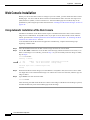
Web Console Installation A-2
Using Automatic Installation of the Web Console
A-2
Installing the Web Console from the PCMCIA Disk A-3
Installing the Web Console from a TFTP Server A-3
Running the Web Console A-4
Using the Web Console
A-4
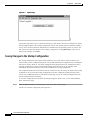
Making Changes with the Web Console A-4
Changing the Current Configuration A-5
Saving Changes to the Startup Configuration A-6
Accessing the Web Console
A-7
Basic System Configuration Page A-8
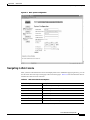
Navigating in Web Console A-9
Entering Basic Configuration Parameters
A-10
Entering Advanced Configuration Parameters
System Reload Options A-12
Configuring Redundancy A-13
Enabling CPU, Slot, and Subslot Redundancy
IP Address Management
A-10
A-13
A-14
Setting the Management IP Configuration
Setting Static Routes A-15
A-14
Cisco 6400 Software Setup Guide
viii
OL-1183-04
Contents
Adding and Removing Domain Name Servers
A-16
SNMP Management A-16
Entering System Options A-17
Entering Community Strings A-18
Adding Trap Managers
NRP Status
A-18
A-19
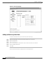
Subscriber Management A-19
Adding and Removing Subscribers
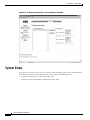
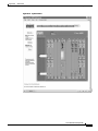
System Status
A-22
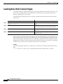
Loading New Web Console Pages
A PPE NDI X
B
A-20
A-24
Upgrading Software on the Cisco 6400
Recommendations
B-1
B-1
Upgrading Software on Nonredundant NRP-1s B-2
Example—Upgrading the Nonredundant NRP-1 B-3
Upgrading Software on Nonredundant NRP-2s and NRP-2SVs
Upgrading Software on Nonredundant NSPs
B-4
B-5
Example—Upgrading the Nonredundant NSP
B-6
Upgrading Software on Redundant NRP-1s B-8
Upgrade the Images on the Secondary NRP-1 B-8
Identify the New System Image as the Startup Image for the Secondary NRP-1
Ensuring That the New System Image Is the First File in the Flash Memory
Updating the Boot System Variable B-10
Reload the Secondary NRP-1 B-10
B-9
B-9
Upgrade the Images on the Primary NRP-1 B-10
Identify the New System Image as the Startup Image for the Primary NRP-1 B-11
Ensuring That the New System Image Is the First File in Flash Memory B-11
Updating the Boot System Variable B-12
Switch the Primary and Secondary NRP-1s B-12
Example—Upgrading Redundant NRP-1s B-12
Upgrading the Images on the Secondary NRP-1 B-13
Identifying the New Image as the Startup Image B-13
Reloading the Secondary NRP-1 B-13
Upgrading the Images on the Primary NRP-1 B-14
Switching the Primary and Secondary NRP-1s B-14
Upgrading Software on Redundant NSPs
Prerequisites B-15
B-14
Upgrade the Secondary NSP Images
B-15
Cisco 6400 Software Setup Guide
OL-1183-04
ix
Contents
Reload the Secondary NSP B-15
Upgrade the Primary NSP Images B-16
Switch the Primary and Secondary NSPs
B-17
Example—Upgrading Redundant NSPs B-17
Upgrading the Secondary NSP Images B-17
Reloading the Secondary NSP B-18
Upgrading the Primary NSP Images B-18
Switching the Primary and Secondary NSPs
AP PE N DIX
C
B-19
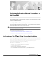
Optimizing the Number of Virtual Connections on the Cisco 6400
C-1
An Overview of the ITT and Virtual Connection Limitations C-1
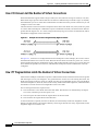
How VCI Values Limit the Number of Virtual Connections C-2
How ITT Fragmentation Limits the Number of Virtual Connections
C-2
Guidelines for Maximizing the Number of Virtual Connections C-3
Assigning VCI Values to Maximize the Number of Entries per Block
Verifying VCI Values C-3
Specifying the Minimum ITT Block Size C-4
Verifying the Minimum ITT Block Size C-4
Using Automatic Determination of the Minimum ITT Block Size
C-3
C-5
Verifying Automatic Determination of the Minimum ITT Block Size
Shrinking ITT Blocks C-6
Verifying ITT Block Shrinking C-6
Displaying ITT Allocation
C-5
C-6
G L OSS AR Y
I ND EX
Cisco 6400 Software Setup Guide
x
OL-1183-04
Preface
This chapter describes the objectives, organization, and audience of this guide, as well as conventions
and related documentation.
Document Objectives
The purpose of this guide is to help you set up your Cisco 6400 carrier-class broadband aggregator with
a basic configuration and connectivity among the Cisco 6400 components. For external connectivity and
information on deploying the many features supported by the Cisco 6400, see the Cisco 6400 Feature
Guide for your software release.
Related Documentation
To complement the software information provided in this guide, refer to the following documents:
Document
Description
Cisco 6400 Feature Guide
Lists the features supported by the
Cisco 6400, provides references to
cross-platform feature documentation,
and describes deployment of features
that are unique to the Cisco 6400.
Cisco 6400 Command Reference
Describes commands that are unique to
the Cisco 6400 command-line interface
(CLI).
ATM Switch Router Software Configuration Guide
Describes additional ATM features and
functionality that are supported by the
Cisco 6400 node switch processor
(NSP).
ATM and Layer 3 Switch Router Command Reference
Describes additional commands
supported by the Cisco 6400 NSP.
Cisco IOS Configuration Guides and Command References
Describes extensive Cisco IOS features
and commands that apply to the
Cisco6400.
Cisco 6400 Software Setup Guide
OL-1183-04
xi
Preface
Audience
Audience
This guide is designed for the system administrator who will be responsible for setting up the CiscoIOS
software on the Cisco6400. The system administrator should be familiar with the installation of
high-end networking equipment.
This guide is intended primarily for the following audiences:
•
Customers with technical networking background and experience
•
Customers who support dial-in users
•
System administrators who are familiar with the fundamentals of router-based internetworking, but
who may not be familiar with CiscoIOS software
•
System administrators who are responsible for installing and configuring internetworking
equipment, and who are familiar with Cisco IOS software
Organization
The Cisco 6400 Software Setup Guide is organized into the following chapters and appendixes:
Chapter 1
Product Overview
Describes the Cisco 6400 system and network
management options.
Chapter 2
Basic NSP Configuration
Describes how to perform basic configuration
for the NSP.
Chapter 3
Basic NRP Configuration
Describes how to perform basic configuration
for the NRP-1, NRP-2, and NRP-2SV.
Chapter 4
Node Line Card Interface
Configuration
Describes how to manually configure the
ATM interfaces for the NLCs.
Chapter 5
Redundancy and SONET APS
Configuration
Describes how to configure redundancy
among the NSP, NRP, and NLC components.
Chapter 6
SNMP, RMON, and Alarm
Configuration
Describes how to use SNMP, RMON, and
alarms on the Cisco 6400.
Appendix A
Web Console
Describes how to install and use the Web
Console application.
Appendix B
Upgrading Software on the Cisco
6400
Describes how to upgrade software images on
the Cisco 6400.
Appendix C
Optimizing the Number of Virtual Describes how to optimize the number of
Connections on the Cisco 6400
virtual connections on the Cisco 6400.
Glossary
—
Defines the acronyms and terms used in this
guide.
Cisco 6400 Software Setup Guide
xii
OL-1183-04
Preface
Conventions
Conventions
This section describes the following conventions used by this guide:
•
Command Syntax
•
Examples
•
Keyboard
•
Notes, Timesavers, Tips, Cautions, and Warnings
Command Syntax
Descriptions of command syntax use the following conventions:
Convention
Description
boldface
Indicates commands and keywords that are entered literally as shown.
italics
Indicates arguments for which you supply values; in contexts that do not allow
italics, arguments are enclosed in angle brackets (< >).
[x]
Keywords or arguments that appear within square brackets are optional.
{x | y | z}
A choice of required keywords (represented by x, y, and z) appears in braces
separated by vertical bars. You must select one.
[x {y | z}]
Braces and vertical bars within square brackets indicate a required choice
within an optional element. You do not need to enter the optional element. If
you do, you have some required choices.
Examples
Examples use the following conventions:
Convention
Description
screen
Shows an example of information displayed on the screen.
boldface screen
Shows an example of information that you must enter.
<
Nonprinting characters, such as passwords, appear in angled brackets.
>
Exclamation points at the beginning of a line indicate a comment line.
Exclamation points are also displayed by the Cisco IOS software for certain
processes.
!
[
]
prompt>
prompt#
Default responses to system prompts appear in square brackets.
Examples that contain system prompts denote interactive sessions, indicating
the commands that you should enter at the prompt. The system prompt
indicates the current level of the EXEC command interpreter. For example, the
prompt router> indicates that you should be at the user level, and the prompt
router# indicates that you should be at the privileged level. Access to the
privileged level usually requires a password.
Cisco 6400 Software Setup Guide
OL-1183-04
xiii
Preface
Obtaining Documentation
Keyboard
This guide uses the following conventions for typing keys:
Convention
Description
Z
Keys are indicated in capital letters but are not case sensitive.
^ orCtrl
Represents the Control key. For example, when you read ^D or Ctrl-D , you
should hold down the Control key while you press the D key.
Notes, Timesavers, Tips, Cautions, and Warnings
The following conventions are used to attract the reader's attention:
Note
Timesaver
Tip
Means reader take note. Notes contain helpful suggestions or references to materials not contained in
this manual.
Means the described action saves time. You can save time by performing the action described in the
paragraph.
Means the following information might help you solve a problem.
Caution
Means reader be careful . You are capable of doing something that might result in equipment damage or
loss of data.
Warning
This warning symbol means danger. You are in a situation that could cause bodily injury. Before you
work on any equipment, be aware of the hazards involved with electrical circuitry and be familiar
with standard practices for preventing accidents. To see translations of the warnings that appear in
this publication, refer to the Regulatory Compliance and Safety Information document that
accompanied this device.
Obtaining Documentation
The following sections provide sources for obtaining documentation from Cisco Systems.
World Wide Web
You can access the most current Cisco documentation on the World Wide Web at the following sites:
•
http://www.cisco.com
Cisco 6400 Software Setup Guide
xiv
OL-1183-04
Preface
Obtaining Technical Assistance
•
http://www-china.cisco.com
•
http://www-europe.cisco.com
Documentation CD-ROM
Cisco documentation and additional literature are available in a CD-ROM package, which ships
withyour product. The Documentation CD-ROM is updated monthly and may be more current than
printed documentation. The CD-ROM package is available as a single unit or as an annualsubscription.
Ordering Documentation
Cisco documentation is available in the following ways:
•
Registered Cisco Direct Customers can order Cisco Product documentation from the Networking
Products MarketPlace:
http://www.cisco.com/cgi-bin/order/order_root.pl
•
Registered Cisco.com users can order the Documentation CD-ROM through the online Subscription
Store:
http://www.cisco.com/go/subscription
•
Nonregistered CCO users can order documentation through a local account representative by calling
Cisco corporate headquarters (California, USA) at 408526-7208 or, in North America, by calling
800 553-NETS(6387).
Documentation Feedback
If you are reading Cisco product documentation on the World Wide Web, you can submit technical
comments electronically. Click Feedback in the toolbar and select Documentation. After you complete
the form, click Submit to send it to Cisco.
You can e-mail your comments to [email protected].
To submit your comments by mail, for your convenience many documents contain a response card
behind the front cover. Otherwise, you can mail your comments to the following address:
Cisco Systems, Inc.
Document Resource Connection
170 West Tasman Drive
San Jose, CA 95134-9883
We appreciate your comments.
Obtaining Technical Assistance
Cisco provides Cisco.com as a starting point for all technical assistance. Customers and partners can
obtain documentation, troubleshooting tips, and sample configurations from online tools. For Cisco.com
registered users, additional troubleshooting tools are available from the TAC website.
Cisco 6400 Software Setup Guide
OL-1183-04
xv
Preface
Obtaining Technical Assistance
Cisco.com
Cisco.com is the foundation of a suite of interactive, networked services that provides immediate, open
access to Cisco information and resources at anytime, from anywhere in the world. This highly
integrated Internet application is a powerful, easy-to-use tool for doing business with Cisco.
Cisco.com provides a broad range of features and services to help customers and partners streamline
business processes and improve productivity. Through Cisco.com, you can find information about Cisco
and our networking solutions, services, and programs. In addition, you can resolve technical issues with
online technical support, download and test software packages, and order Cisco learning materials and
merchandise. Valuable online skill assessment, training, and certification programs are also available.
Customers and partners can self-register on Cisco.com to obtain additional personalized information and
services. Registered users can order products, check on the status of an order, access technical support,
and view benefits specific to their relationships with Cisco.
To access Cisco.com, go to the following website:
http://www.cisco.com
Technical Assistance Center
The Cisco TAC website is available to all customers who need technical assistance with a Cisco product
or technology that is under warranty or covered by a maintenance contract.
Contacting TAC by Using the Cisco TAC Website
If you have a priority level 3 (P3) or priority level 4 (P4) problem, contact TAC by going to the TAC
website:
http://www.cisco.com/tac
P3 and P4 level problems are defined as follows:
•
P3—Your network performance is degraded. Network functionality is noticeably impaired, but most
business operations continue.
•
P4—You need information or assistance on Cisco product capabilities, product installation, or basic
product configuration.
In each of the above cases, use the Cisco TAC website to quickly find answers to your questions.
To register for Cisco.com, go to the following website:
http://www.cisco.com/register/
If you cannot resolve your technical issue by using the TAC online resources, Cisco.com registered users
can open a case online by using the TAC Case Open tool at the following website:
http://www.cisco.com/tac/caseopen
Contacting TAC by Telephone
If you have a priority level 1(P1) or priority level 2 (P2) problem, contact TAC by telephone and
immediately open a case. To obtain a directory of toll-free numbers for your country, go to the following
website:
http://www.cisco.com/warp/public/687/Directory/DirTAC.shtml
Cisco 6400 Software Setup Guide
xvi
OL-1183-04
Preface
Obtaining Technical Assistance
P1 and P2 level problems are defined as follows:
•
P1—Your production network is down, causing a critical impact to business operations if service is
not restored quickly. No workaround is available.
•
P2—Your production network is severely degraded, affecting significant aspects of your business
operations. No workaround is available.
Cisco 6400 Software Setup Guide
OL-1183-04
xvii
Preface
Obtaining Technical Assistance
Cisco 6400 Software Setup Guide
xviii
OL-1183-04
C H A P T E R
1
Product Overview
The Cisco 6400 carrier-class broadband aggregator is a high-performance, scalable service gateway that
enables the selection and delivery of broadband network services, virtual private networks (VPNs), and
voice- and entertainment-driven traffic over the full suite of access media. The Cisco 6400 combines the
richness of Cisco IOS software, ATM switching and routing capabilities, and value-added service
selection in a modular, scalable, redundant, Network Equipment Building Systems (NEBS) certified and
ETSI form factor.
The Cisco 6400 consists of a fault-tolerant midrange ATM switching core and multiple fault-tolerant
routing engines. The ATM switch, based on Catalyst 8500 + Per-Flow Queuing (PFQ) technology,
provides the necessary ATM switching and traffic management capabilities, while the router modules
enable the service provider to offer scalable Layer 3 services. ATM interfaces connect the Cisco 6400
to dial access servers, digital subscriber line access multiplexers (DSLAMs), and Cisco IP DSL
switches, and ATM and packet interfaces connect to the network core. The Cisco 6400 is designed for
use in high-availability environments such as operating companies’ central offices (directly or via
co-location), Internet service provider (ISP) offices, and corporate premises. As such, it includes switch,
router, and line card redundancy, as well as 12-inch packaging (key for central office deployment).
The Cisco 6400 can reside within the operating company’s infrastructure (directly or via co-location) to
aggregate access media (DSL, cable, wireless, and dial), serving as the intelligent equal access point that
allows a multitude of operating companies and service providers access to the end users. In addition, the
Cisco 6400 can reside at the network edge between the operating companies and ISP or corporation,
providing the aggregation of sessions and tunnels as well as service and network selection capabilities
required in the delivery of advanced broadband services.
Cisco 6400 Software Setup Guide
OL-1183-04
1-1
Chapter1
Product Overview
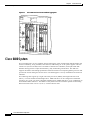
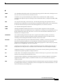
Cisco 6400 System
Figure1-1
Cisco 6400 Carrier-Class Broadband Aggregator
Cisco 6400 System
The Cisco6400 uses a ten-slot, modular chassis featuring the option of half-height and full-height card
and slot redundancy, along with dual, fault-tolerant, load-sharing AC or DC power supplies. The two
central slots (slot 0A and 0B) in the Cisco6400 are dedicated to redundant, field-replaceable NSP
modules that support the 5-Gbps shared memory, fully nonblocking switch fabric. The NSP also
supports the feature card and high-performance reduced instruction set computing (RISC) processor that
provides the central intelligence for the device. The NSP supports a variety of backbone and wide-area
interfaces.
The remaining slots support up to eight node route processors (NRPs), full-height node line cards
(NLCs), or carrier modules for half-height NLCs. NRPs and NLCs can be configured for redundant
operation. As a result, you can have multiple redundant pairs of NRPs and NLCs, or any combination of
nonredundant NRPs and NLCs. The NRPs are fully functional router modules capable of terminating
PPP sessions delivered over OC-12, OC-3, or DS3 node line cards.
Cisco 6400 Software Setup Guide
1-2
OL-1183-04
Chapter1
Product Overview
Cisco 6400 System
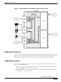
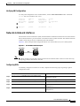
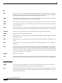
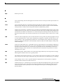
Figure1-2
Simple Schematic of Cisco 6400 Internal and External Connectivity
Node Switch Processor
The Cisco 6400 NSP provides ATM switching functionality. The NSP uses permanent virtual circuits
(PVCs) or permanent virtual paths (PVP) to direct ATM cells between the NRP and ATM interface. The
NSP also controls and monitors the Cisco 6400 system, including component NLCs and NRPs.
Node Route Processor
The Cisco 6400 supports three node route processors, designated as NRP-1, NRP-2, and NRP-2SV (see
Table1-1 for major differences):
•
NRP-1—Incorporates a 100-Mbps Fast Ethernet interface for connecting into an IP network and has
processing capability for OC-3 rate of user traffic.
•
NRP-2 and NRP-2SV —Provides a Gigabit Ethernet interface and sufficient processing capability
for handling OC-12 rate of user traffic.
Cisco 6400 Software Setup Guide
OL-1183-04
1-3
Chapter1
Product Overview
Cisco 6400 System
The Cisco6400 can contain multiple NRP modules, configured to operate independently or as 1+1
redundant pairs. The NRP receives traffic from NLC interface ports through the NSP ATM switch,
reassembles the ATM cells into packets, processes (for example, routes or bridges) the packets, and then
does one of the following:
Table1-1
•
Segments the packets into ATM cells and sends them back to the NSP for transmission out of
another NLC interface
•
Sends the traffic out the Fast Ethernet (NRP-1) or Gigabit Ethernet (NRP-2) interface
Differences Between NRP-1 and NRP-2 or NRP-2SV
Feature or Capability
NRP-1
NRP-2 and NRP-2SV1
Session scalability
Hardware supports as many as
2000sessions per NRP-1.
Hardware supports as many as
16,000sessions per NRP-2.
Physical interfaces
Faceplate interfaces:
Faceplate interfaces:
•
Console port
•
•
Auxiliary port
•
Ethernet port
•
622-Mbps ATM interface
•
Fast Ethernet port
•
PAM mailbox serial interface2
Gigabit Ethernet interface
Backplane interfaces:
Backplane interfaces:
•
155-Mbps ATM interface
•
Backplane Ethernet (BPE)
Location of startup configurations
and crash information
NRP-1 memory
(built-in or internal Flash)
PCMCIA3 disk on NSP.
Message logging
Messages are logged on the NRP-1
as a local message.
NRP-2 messages are logged on both the
NSP and NRP-2. NRP-2 messages on the
NSP include the NRP-2 slot number.
Console line access
Direct external connection to NRP-1
console port or auxiliary port.
Indirect external connection via the NSP.
NSP contains a virtual communication
server to access NRP-2 console.
ROMMON4
ROMMON not upgradable;
NRP-1 ROM state information stored
locally on NRP-1.
ROMMON is upgradable;
NRP-2 ROM state information is stored
on the NSP PCMCIA disk.
SNMP5
Standard SNMP services.
Standard SNMP services, or the NSP
can be used as the proxy forwarder.
LED display
None.
On faceplate.
1 . Differences between the NRP-2 and NRP-2SV vary by software release. See the release notes for your specific software images.
2 . The PAM mailbox serial interface is used for internal system communication. Do not attempt to configure serial interfaces on the Cisco 6400.
3 . PCMCIA = Personal Computer Memory Card International Association
4 . ROMMON = ROM monitor
5 . SNMP = Simple Network Management Protocol
Cisco 6400 Software Setup Guide
1-4
OL-1183-04
Chapter1
Product Overview
Network Management—Cisco 6400 SCM
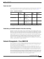
Node Line Card
NLCs provide ATM interfaces for the Cisco 6400 system and are controlled by the NSP. The three types
of NLC available for the Cisco 6400 each offer a different interface type, as shown in Table1-2.
Table1-2
Supported Cisco 6400 NLCs
NLC
Bandwidth
Cable
Height
Number
of Ports
OC-12/STM-4
622 Mbps
SONET 1
single-mode
fiber-optic cable
Full-height
1
OC-3/STM-1 SM
155 Mbps
SONET
single-mode
fiber-optic cable
Half-height2
2
OC-3/STM-1 MM
155 Mbps
SONET
multimode
fiber-optic cable
Half-height
2
DS3
45 Mbps
Coaxial cable
Half-height
2
1 . SONET = Synchronous Optical Network
2 . Half-height NLCs require carrier modules, each of which hold two half-height NLCs with covers for empty slots.
Redundancy and SONET Automatic Protection Switching
Redundancy for both the NSP and NRP is based on enhanced high system availability (EHSA). If the
NRP fails, no virtual connections from the NSP need to be reconfigured. The NRP blades also support
online insertion and removal (OIR). When operating in nonredundant mode, the NRPs appear as separate
network management and routing entities and can be accessed through individual management ports.
SONET automatic protection switching (APS) provides a mechanism to support redundant transmission
circuits between SONET devices. Automatic switchover from the primary or working circuit to the
backup or protection circuit happens when the working circuit fails or degrades. The Cisco 6400
supports 1+1, linear, unidirectional, nonreverting APS operation on its redundant OC-3 and OC-12 NLC
interfaces. SONET APS does not apply to DS3 NLCs.
Network Management—Cisco 6400 SCM
The Cisco 6400 Service Connection Manager (SCM) software provides simplified ATM and Layer 2 and
Layer 3 IP services to access servers and DSLAMs through network and service management of the
Cisco 6400 carrier-class broadband aggregator.
The Cisco 6400 SCM assists you in making network connections by eliminating the need to have
technical knowledge of SNMP and Cisco IOS commands required to establish these connections. It also
streamlines the deployment process for the Cisco6400 aggregator. The Cisco 6400 SCM provides a
service-oriented management view of the Cisco6400 aggregator’s inbound and outbound connections.
The Cisco 6400 SCM is based on the common Cisco Element Management Framework (CEMF), which
is a Sun Solaris UNIX-based element management foundation for many Cisco service provider products.
The Cisco 6400 SCM Element Manager software adds custom windows and modeling behavior to the
standard CEMF to improve management of the Cisco 6400 aggregator hardware.
Cisco 6400 Software Setup Guide
OL-1183-04
1-5
Chapter1
Product Overview
Network Management—Cisco 6400 SCM
For more information, see theCisco 6400 SCM documentation on Cisco.com at
http://www.cisco.com/en/US/products/sw/netmgtsw/ps2142/
Cisco 6400 Software Setup Guide
1-6
OL-1183-04
C H A P T E R
2
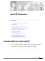
Basic NSP Configuration
This chapter describes how to perform basic configuration for the Cisco 6400 node switch processor
(NSP). The Cisco6400 can contain two NSPs configured for redundancy. This chapter contains the
following sections:
•
Methods Available for Configuring the NSP, page 2-1
•
Checking the Software Release Version, page 2-2
•
DHCP, page 2-3
•
Configuring the System Clock and Hostname, page 2-3
•
ATM Address, page 2-4
•
Network Management Ethernet Interface , page 2-6
•
Internal Cross-Connections, page 2-10
•
Network Clocking, page 2-14
•
Network Routing, page 2-18
•
NRP-2 and NRP-2SV Support, page 2-19
•
Storing the NSP Configuration, page 2-23
•
Verifying the NSP Configuration , page 2-23
•
Using the NSP File Systems and Memory Devices , page 2-24
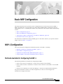
Methods Available for Configuring the NSP
The following methods are available for configuring the NSP:
•
From a local console or workstation—Connect to the console port of the NSP. This connection
allows you to issue command-line interface (CLI) commands directly to the NSP.
•
From a remote console or workstation—Initiate a Telnet connection to the NSP.
•
From the Web Console application—See AppendixA, “ Web Console.”
•
From the Cisco 6400 Service Connection Manager—See theCisco 6400 SCM documentation.
Cisco 6400 Software Setup Guide
OL-1183-04
2-1
Chapter2
Basic NSP Configuration
Checking the Software Release Version
Note
If your Telnet station or Simple Network Management Protocol (SNMP) network management
workstation and the Cisco 6400 are on different networks, you must add a static routing table entry to
the routing table. For information on configuring static routes, see the “Configuring ATM Routing and
PNNI” chapter of the ATM Switch Router Software Configuration Guide.
For general information on basic Cisco IOS configuration, see the Cisco IOS Configuration
Fundamentals Configuration Guide associated with your software release level.
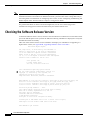
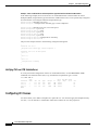
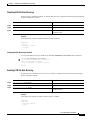
Checking the Software Release Version
To check the software release version, connect a console terminal or a terminal server to the NSP console
port on the NSP faceplate. After you boot the NSP, the following information is displayed to verify that
the NSP has booted successfully.
Take note of the software release version included in the display. For information on upgrading to a
higher release version, see AppendixB, “Upgrading Software on the Cisco 6400.”
Restricted Rights Legend
Use, duplication, or disclosure by the Government is
subject to restrictions as set forth in subparagraph
(c) of the Commercial Computer Software - Restricted
Rights clause at FAR sec. 52.227-19 and subparagraph
(c) (1) (ii) of the Rights in Technical Data and Computer
Software clause at DFARS sec. 252.227-7013.
cisco Systems, Inc.
170 West Tasman Drive
San Jose, California 95134-1706
Cisco Internetwork Operating System Software
IOS (tm) C6400 Software (C6400S-WP-M), Version 12.3
Copyright (c) 1986-2002 by Cisco Systems, Inc.
Compiled Tue 18-Sep-02 15:00 by jdoe
Image text-base: 0x60010908, data-base: 0x6069A000
FPGA VERSION: 97/11/25 22:11:51 1383107375 /rhino/fpga/fc_abr_fc3/xil/abr_fpga_r.bit
98/02/24 17:11:36 1332837880 /rhino/fpga/fc_stat_fpga/xilinx/stat_fpga_r.bit
97/11/13 10:03:51 1059421866 /rhino/fpga/fc_traffic_fc3/xil/upc_fpga.bit
97/08/06 13:09:19 288278431 /rhino/fpga/fc_netclk/xilinx/pll_cntl_r.bit
Initializing FC-PFQ hardware ... done.
cisco C6400S (R4600) processor with 131072K bytes of memory.
R4700 CPU at 100Mhz, Implementation 33, Rev 1.0
Last reset from s/w peripheral
2 Ethernet/IEEE 802.3 interface(s)
11 ATM network interface(s)
507K bytes of non-volatile configuration memory.
107520K bytes of ATA PCMCIA card at slot 0 (Sector size 512 bytes).
8192K bytes of Flash internal SIMM (Sector size 256K).
Press RETURN to get started!
Cisco 6400 Software Setup Guide
2-2
OL-1183-04
Chapter2
Basic NSP Configuration
DHCP
DHCP
Dynamic Host Configuration Protocol (DHCP) is the default IP assignment protocol for a new NSP, or
for an NSP that has had its configuration file cleared by means of the erase nvram:startup-config
command. For DHCP, an Ethernet IP address, subnet mask, and the default route are retrieved from the
DHCP server for any interface set with the ip address negotiated command. To configure the DHCP
server, add an entry in the DHCP database using the instructions that came with the server.
Note
The Cisco 6400 performs a DHCP request only if the NME interface is configured with the ip address
negotiated interface configuration command.
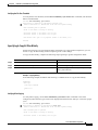
Verifying DHCP
Use the show dhcp lease command to confirm the IP address, subnet mask, default gateway, and static
route information obtained from a DHCP server:
Switch# show dhcp lease
Temp IP addr: 10.1.1.3 for peer on Interface: unknown
Temp sub net mask: 255.255.0.0
DHCP Lease server: 172.18.254.254, state: 3 Bound
DHCP transaction id: 18D9
Lease: 86400 secs, Renewal: 43200 secs, Rebind: 75168 secs
Temp default-gateway addr: 10.1.0.1
Temp ip static route0: dest 172.18.254.254 router 10.1.0.1
Next timer fires after: 00:29:59
Retry count: 0
Client-ID: cisco-0010.7ba9.c600-Ethernet0/0/0
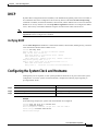
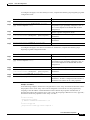
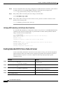
Configuring the System Clock and Hostname
Although they are not required, several system parameters should be set as part of the initial system
configuration. To set the system clock and hostname, complete the following steps beginning in
privileged EXEC mode:
Command
Purpose
Step1
Switch# clock set hh:mm:ss day_of_month month year
Sets the system clock.
Step2
Switch# configure terminal
Enters global configuration mode.
Step3
Switch(config)# hostname name_string
Sets the system hostname.
Example
In the following example, the system clock and hostname are configured:
Switch# clock set 15:01:00 17 October 2002
Switch# configure terminal
Enter configuration commands, one per line.
Switch(config)# hostname Publications
Publications(config)#
End with CNTL/Z.
Cisco 6400 Software Setup Guide
OL-1183-04
2-3
Chapter2
Basic NSP Configuration
ATM Address
Verifying the System Clock and Hostname Configuration
To confirm the system clock setting, use the show clock command:
Publications# show clock
.15:03:12.015 UTC Fri Oct 17 2002
Publications#
To confirm the hostname, check the CLI prompt. The new hostname will appear in the prompt.
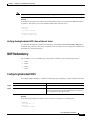
ATM Address
The Cisco 6400 NSP ships with the ATM address autoconfigured, which enables the switch to
automatically configure attached end systems using the Integrated Local Management Interface (ILMI)
protocol. Autoconfiguration also enables the NSP to establish itself as a node in a single-level Private
Network-Network Interface (PNNI) routing domain.
To manually configure the ATM address, see the “Configuring the ATM Address Manually” section on
page2-5.
Note
If you chose to manually change any ATM address, it is important to maintain the uniqueness of the
address across large networks. Refer to the “Configuring ATM Routing and PNNI” chapter in the ATM
Switch Router Software Configuration Guide for PNNI address considerations and for information on
obtaining registered ATM addresses.
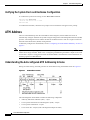
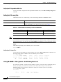
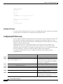
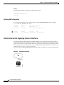
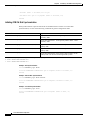
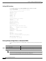
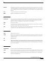
Understanding the Autoconfigured ATM Addressing Scheme
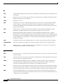
During the initial startup, the NSP generates an ATM address using the defaults shown in Figure2-1 .
Figure2-1
ATM Address Format
The autoconfigured ATM address includes the following components:
•
Authority and format identifier (AFI)—1 byte
•
Cisco-specific International Code Designator (ICD)—2 bytes
•
Cisco-specific information—4 bytes
•
Cisco switch ID—6 bytes (used to distinguish multiple switches)
Cisco 6400 Software Setup Guide
2-4
OL-1183-04
Chapter2
Basic NSP Configuration
ATM Address
Note
The first 13 bytes of the address make up a switch prefix used by ILMI in assigning addresses to end
stations connected to User-Network Interface (UNI) ports.
•
Note
MAC address of the NSP—6 bytes (used to distinguish multiple end system identifier [ESI]
addresses)
Both MAC address fields in the ATM address are the same, but they will not be the same as the address
printed on the chassis label.
•
Selector equals 0—1 byte
Configuring the ATM Address Manually
Manually configuring the ATM address is required:
•
To connect to another system using Interim Interswitch Signaling Protocol (IISP). Using IISP
requires disabling PNNI, which results in no ILMI support.
•
To configure a new ATM address that replaces the previous ATM address and generates a new PNNI
node ID and peer group ID for migrating from flat to hierarchical PNNI.
•
To connect to multiple levels of a PNNI hierarchy.
•
To connect to a service provider network that requires you to use the addressing scheme for that
network.
•
To use a particular style of addressing. For instance, in some circumstances a mnemonic scheme
might be useful for identifying nodes in an ATM network.
To configure a new ATM address, refer to the chapter “Configuring ATM and PNNI” in the ATM Switch
Router Software Configuration Guide.
Caution
ATM addressing can lead to conflicts if not configured correctly. If you are configuring a new ATM
address, the old one must be completely removed from the configuration.
Example
The following example shows how to change the active ATM address, create a new address, verify that
it exists, and then delete the current active address. Using the ellipses (...) adds the default Media Access
Control (MAC) address as the last six bytes.
Switch(config)# atm address 47.0091.8100.5670.0000.0ca7.ce01...
Switch(config)# end
Switch# show atm addresses
Switch Address(es):
47.00918100000000410B0A1081.00410B0A1081.00 active
47.00918100567000000CA7CE01.00410B0A1081.00
Soft VC Address(es):
47.0091.8100.0000.0041.0b0a.1081.4000.0c80.0000.00
47.0091.8100.0000.0041.0b0a.1081.4000.0c80.0000.63
47.0091.8100.0000.0041.0b0a.1081.4000.0c80.0010.00
47.0091.8100.0000.0041.0b0a.1081.4000.0c80.0020.00
ATM0/0/0
ATM0/0/0.99
ATM0/0/1
ATM0/0/2
Cisco 6400 Software Setup Guide
OL-1183-04
2-5
Chapter2
Basic NSP Configuration
Network Management Ethernet Interface
47.0091.8100.0000.0041.0b0a.1081.4000.0c80.0030.00
47.0091.8100.0000.0041.0b0a.1081.4000.0c80.1000.00
47.0091.8100.0000.0041.0b0a.1081.4000.0c80.1010.00
47.0091.8100.0000.0041.0b0a.1081.4000.0c80.1020.00
47.0091.8100.0000.0041.0b0a.1081.4000.0c80.1030.00
47.0091.8100.0000.0041.0b0a.1081.4000.0c80.8000.00
47.0091.8100.0000.0041.0b0a.1081.4000.0c80.8010.00
47.0091.8100.0000.0041.0b0a.1081.4000.0c80.8020.00
47.0091.8100.0000.0041.0b0a.1081.4000.0c80.8030.00
47.0091.8100.0000.0041.0b0a.1081.4000.0c80.9000.00
47.0091.8100.0000.0041.0b0a.1081.4000.0c80.9010.00
47.0091.8100.0000.0041.0b0a.1081.4000.0c80.9020.00
47.0091.8100.0000.0041.0b0a.1081.4000.0c80.9030.00
ATM0/0/3
ATM0/1/0
ATM0/1/1
ATM0/1/2
ATM0/1/3
ATM1/0/0
ATM1/0/1
ATM1/0/2
ATM1/0/3
ATM1/1/0
ATM1/1/1
ATM1/1/2
ATM1/1/3
ILMI Switch Prefix(es):
47.0091.8100.0000.0041.0b0a.1081
47.0091.8100.0000.0060.3e5a.db01
ILMI Configured Interface Prefix(es):
LECS Address(es):
Switch# configure terminal
Switch(config)# no atm address 47.0091.8100.0000.0041.0b0a.1081...
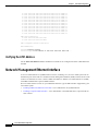
Verifying the ATM Address
Use the show atm addresses EXEC command to confirm correct configuration of the ATM address for
the NSP.
Network Management Ethernet Interface
As of Cisco IOS Release 12.0(5)DB and later releases, including 12.3, the Cisco 6400 system can use
the Ethernet port on the NSP as a combined network management Ethernet (NME) interface for all cards
in the Cisco 6400 chassis. This is called “NME consolidation.” Before Cisco IOS Release 12.0(5)DB,
each NRP and NSP used a separate NME interface.
The Cisco IOS software version on your NSP determines the type of NME interface supported by your
Cisco 6400 system:
•
Enabling NME Consolidation on the NSP—Cisco IOS Release 12.0(5)DB and later
•
Enabling a Separate NME Interface —Cisco IOS Release 12.0(4)DB and earlier, optional task for
later releases
Cisco 6400 Software Setup Guide
2-6
OL-1183-04
Chapter2
Basic NSP Configuration
Network Management Ethernet Interface
Enabling NME Consolidation on the NSP
The method used to enable the combined NME interface on the NSP depends on whether or not the NSP
was upgraded to or preloaded with Cisco IOS Release 12.0(5)DB or later.
Enabling NME Consolidation on a New NSP Preloaded with Cisco IOS Release 12.0(5)DB or Later
On an NSP that is preloaded with a Cisco IOS Release 12.0(5)DB or later software image, NME
consolidation is already included in the default configuration.
If your NSP does not use a DHCP server to obtain an IP address, you must configure a static IP address.
Complete the following steps beginning in global configuration mode:
Command
Purpose
Step1
Switch(config)# interface BV11
Selects the interface used for NME consolidation.
Step2
Switch(config-if)# ip address address subnet
Configures the static IP and subnetwork address.
Example—NME Consolidation
!
interface BVI1
ip address 172.20.40.93 255.255.255.0
!
Enabling NME Consolidation on an NSP Upgraded to Cisco IOS Release 12.0(5)DB or Later
To enable NME consolidation on an NSP upgraded from a Cisco IOS Release 12.0(4)DB or earlier
software image, complete the following tasks:
•
Task 1: Removing the IP Addresses from the Ethernet 0/0/0 and Ethernet 0/0/1 Interfaces
•
Task 2: Setting up the Bridge Group
•
Task 3: Configuring the NME Interface
Task 1: Removing the IP Addresses from the Ethernet 0/0/0 and Ethernet 0/0/1 Interfaces
To remove the IP addresses from the Ethernet 0/0/0 and Ethernet 0/0/1 interfaces, complete the
following steps beginning in global configuration mode:
Command
Purpose
Step1
Switch(config)# interface ethernet 0/0/0
Selects the Ethernet 0/0/0 interface.
Step2
Switch(config-if)# no ip address
Removes the IP address from the interface.
Step3
Switch(config-if)# interface ethernet 0/0/1
Selects the Ethernet 0/0/1 interface.
Step4
Switch(config-if)# no ip address
Removes the IP address from the interface.
Step5
Switch(config-if)# exit
Returns to global configuration mode
Cisco 6400 Software Setup Guide
OL-1183-04
2-7
Chapter2
Basic NSP Configuration
Network Management Ethernet Interface
Task 2: Setting up the Bridge Group
To set up the bridge group, complete the following steps beginning in global configuration mode:
Command
Purpose
Step1
Switch(config)# bridge irb
Enables integrated routing and bridging.
Step2
Switch(config)# bridge 1 protocol ieee
Selects the IEEE Ethernet Spanning-Tree
Protocol for bridge group 1.
Step3
Switch(config)# bridge 1 route ip
Enables IP routing in bridge group 1.
Step4
Switch(config-if)# interface ethernet 0/0/1
Selects the Ethernet 0/0/1 interface.
Step5
Switch(config-if)# bridge-group 1
Assigns the Ethernet 0/0/1 interface to bridge
group 1.
Task 3: Configuring the NME Interface
To configure the NME interface, complete the following steps beginning in global configuration mode:
Command
Purpose
Step1
Switch(config)# interface BVI1
Creates or selects the interface used for NME
consolidation.
Step2
Switch(config-if)# ip address address subnet
Configures a static IP address and
subnetwork address.
or, if using DHCP,
Switch(config-if)# ip address negotiated
Enables the interface to obtain an IP address,
subnet mask, router address, and static routes
from a DHCP server.
Example—NME Consolidation Configuration on the NSP
!
bridge irb
!
bridge 1 protocol ieee
bridge 1 route ip
!
interface ethernet 0/0/0
no ip address
!
interface ethernet 0/0/1
no ip address
bridge-group 1
!
interface BVI1
ip address 172.20.40.93 255.255.255.0
!
Cisco 6400 Software Setup Guide
2-8
OL-1183-04
Chapter2
Basic NSP Configuration
Network Management Ethernet Interface
Enabling NME Consolidation on the NRP
In addition to configuring the NSP for NME consolidation, you must configure the NRP Ethernet
interfaces to also support NME consolidation. Complete the following steps, beginning in global
configuration mode:
Command
Purpose
Step1
Router(config)# interface ethernet 0/0/0
Selects the Ethernet 0/0/0 interface.
Step2
Router(config-if)# no ip address
Removes the IP address from the interface.
Step3
Router(config-if)# interface ethernet 0/0/1
Selects the Ethernet 0/0/1 interface.
Step4
Router(config-if)# ip address address subnet
Configures a static IP address and subnetwork
address. Use the same subnet from the
Ethernet0/0/1 interface on the NSP.
Example—NME Consolidation Configuration on the NRP
!
interface ethernet 0/0/0
no ip address
!
interface ethernet 0/0/1
ip address 172.20.40.10 255.255.255.0
!
Enabling a Separate NME Interface
Cisco IOS Release 12.0(4)DB and earlier images do not support NME consolidation. You must
configure the NSP Ethernet interface as a separate NME interface that is unable to handle network
management of the NRPs in the Cisco 6400 system.
Enabling the NME on an NSP Running Cisco IOS Release 12.0(4)DB or Earlier
Complete the following steps beginning in global configuration mode:
Command
Purpose
Step1
Switch(config)# interface ethernet 0/0/0
Selects the NME interface to be configured.
Step2
Switch(config-if)# ip address address subnet
Configures a static IP address and subnetwork
address.
or, if using DHCP,
Switch(config-if)# ip address negotiated
Enables the interface to obtain an IP address,
subnet mask, router address, and static routes
from a DHCP server.
Example—Separate NME
In the following example, the NSP is configured to use the separate NME interface:
!
interface ethernet 0/0/0
ip address negotiated
Cisco 6400 Software Setup Guide
OL-1183-04
2-9
Chapter2
Basic NSP Configuration
Internal Cross-Connections
!
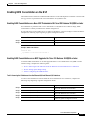
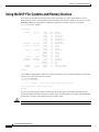
Verifying the NME Interface Configuration
Use the show interface EXEC command to verify successful configuration of the NME interface on the
NSP. If the NSP is configured for NME consolidation, use show interface BVI 1 . On an NSP configured
to use a separate NME interface, use show interface ethernet 0/0/0. Check that the output shows:
•
That the NME interface and line protocol is “up”
•
A valid IP address
•
That packets are input and output
Switch# show interface BVI 1
BVI1 is up, line protocol is up
Hardware is BVI, address is 0050.736f.5756 (bia 0000.0000.0000)
Internet address is 172.194.71.11/24
MTU 4470 bytes, BW 10000 Kbit, DLY 5000 usec,
reliability 255/255, txload 1/255, rxload 1/255
Encapsulation ARPA, loopback not set
ARP type: ARPA, ARP Timeout 04:00:00
Last input never, output never, output hang never
Last clearing of "show interface" counters never
Queueing strategy: fifo
Output queue 0/0, 0 drops; input queue 0/75, 0 drops
5 minute input rate 0 bits/sec, 0 packets/sec
5 minute output rate 0 bits/sec, 0 packets/sec
53 packets input , 3180 bytes, 0 no buffer
Received 0 broadcasts, 0 runts, 0 giants, 0 throttles
0 input errors, 0 CRC, 0 frame, 0 overrun, 0 ignored, 0 abort
57 packets output, 0 bytes, 0 underruns
0 output errors, 0 collisions, 0 interface resets
0 output buffer failures, 0 output buffers swapped out
Switch#
Internal Cross-Connections
The following sections describe minimal procedures for creating virtual circuits (VCs) and virtual paths
(VPs).
Note
Soft VCs between the NRP and NSP are not supported.
For more information, see the following chapters of the ATM Switch Router Software Configuration
Guide:
•
“Configuring Virtual Connections” (VCs)
•
“Configuring ATM Network Interfaces” (VPs, including shared and hierarchical VP tunnels)
Cisco 6400 Software Setup Guide
2-10
OL-1183-04
Chapter2
Basic NSP Configuration
Internal Cross-Connections
Configuring PVCs (VC Switching)
A permanent virtual circuit (PVC) is a permanent logical connection that you must configure manually,
from source to destination, through the ATM network. Once configured, the ATM network maintains
the connection at all times, regardless of traffic flow. That is, the connection is always up whether or not
there is traffic to send.
The Cisco 6400 uses PVCs to pass traffic between the node line card (NLC) ATM interfaces and node
route processors (NRPs). Typically, when VC switching is used, each subscriber is bound to a specific
NRP and should be configured as a separate PVC. If the Cisco 6400 is used as an ATM switch, VCs are
simply connected between the ATM interfaces.
To create a PVC between an ATM interface and an NRP, complete the following steps beginning in
global configuration mode:
Command
Purpose
Step1
Switch(config)# interface atm slot/subslot/port
Selects the NLC interface to be configured.
Step2
Switch(config-if)# atm pvc vpi vci interface atm
slot/subslot/port vpi vci
Configures the PVC, using the slot/subslot/port of the
NRP to which you want to connect the NLC.
You must also configure the PVC on the NRP side. For instructions on configuring PVCs on the NRP,
see the “Permanent Virtual Circuits ” section on page3-20 .
Example—Internal PVC
In the following example, an internal PVC is configured between the NLC ATM interface 1/0/0 and an
NRP in slot 5. Both the NRP and NSP must be configured to create the PVC.
Configuration fragment on the NSP:
!
interface atm 1/0/0
atm pvc 0 50 interface atm 5/0/0 2 100
!
Configuration fragment on the NRP:
!
interface atm 0/0/0
pvc 2/100
!
Configuring PVPs (VP Switching)
A permanent virtual path (PVP) allows you to connect two ATM switch routers at different locations
across a public ATM network that does not support ATM signaling. Signaling traffic is mapped into the
PVP, and the switches allocate a virtual channel connection (VCC) on that VP, instead of the default
VP0. This mapping allows the signaling traffic to pass transparently through the public network. VP
switching also provides NSP redundancy at the ATM layer.
Cisco 6400 Software Setup Guide
OL-1183-04
2-11
Chapter2
Basic NSP Configuration
Internal Cross-Connections
To create a PVP between an ATM interface and an NRP, complete the following steps beginning in
global configuration mode:
Command
Purpose
Step1
Switch(config)# interface atm slot/subslot/port
Selects the NLC interface to be configured.
Step2
Switch(config-if)# atm pvp vpi interface atm
slot/subslot/port vpi
Configures the PVP, using the slot/subslot/port of the
NRP to which you want to connect the NLC.
You must also configure PVCs on the NRP that will use the VP switch. For instructions on configuring
PVCs on the NRP, see the “Permanent Virtual Circuits” section on page3-20.
Example—Internal PVP
In the following example, an internal PVP is configured between the NLC ATM interface at 1/0/0 and
an NRP in slot 5. Both the NRP and NSP must be configured to create the PVP.
Configuration fragment on the NSP:
!
interface atm 1/0/0
atm pvp 0 interface atm 5/0/0 2
!
Configuration fragment on the NRP:
!
interface atm 0/0/0
pvc 2/100
pvc 2/101
pvc 2/102
!
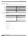
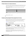
Verifying Internal Cross-Connections
Use the show atm vc EXEC command to confirm the status of ATM virtual channels:
Switch# show atm vc
Interface
VPI
ATM0/0/0
0
ATM0/0/0
0
ATM0/0/0
0
ATM0/0/0
0
ATM0/0/0
0
ATM0/0/0
0
ATM0/0/0
0
ATM0/0/0
0
ATM0/0/0
0
ATM0/0/0
0
ATM0/0/0
0
Interface
VPI
ATM0/0/0
0
ATM0/0/0
0
ATM0/0/0
0
ATM0/0/0
0
ATM0/0/0
0
ATM0/0/0
0
ATM0/0/0
0
ATM0/0/0
0
VCI
35
36
37
38
39
40
41
42
43
44
45
VCI
46
47
48
49
50
51
52
53
Type
PVC
PVC
PVC
PVC
PVC
PVC
PVC
PVC
PVC
PVC
PVC
Type
PVC
PVC
PVC
PVC
PVC
PVC
PVC
PVC
X-Interface
ATM1/0/0
ATM1/0/0
ATM1/0/1
ATM1/0/1
ATM5/0/0
ATM5/0/0
ATM6/0/0
ATM6/0/0
ATM7/1/0
ATM7/1/0
ATM7/1/1
X-Interface
ATM7/1/1
ATM8/1/0
ATM8/1/0
ATM8/1/1
ATM8/1/1
ATM7/0/0
ATM7/0/0
ATM7/0/1
X-VPI X-VCI
0
16
0
5
0
16
0
5
0
16
0
5
0
16
0
5
0
16
0
5
0
16
X-VPI X-VCI
0
5
0
16
0
5
0
16
0
5
0
16
0
5
0
16
Encap
ILMI
QSAAL
ILMI
QSAAL
ILMI
QSAAL
ILMI
QSAAL
ILMI
QSAAL
ILMI
Encap
QSAAL
ILMI
QSAAL
ILMI
QSAAL
ILMI
QSAAL
ILMI
Status
DN
DN
DN
DN
DN
DN
DN
DN
UP
UP
DN
Status
DN
UP
UP
DN
DN
UP
UP
DN
Cisco 6400 Software Setup Guide
2-12
OL-1183-04
Chapter2
Basic NSP Configuration
Internal Cross-Connections
ATM0/0/0
ATM0/0/0
ATM0/0/0
ATM0/0/0
ATM1/0/0
ATM1/0/0
ATM1/0/1
Interface
ATM1/0/1
ATM5/0/0
ATM5/0/0
ATM6/0/0
ATM6/0/0
ATM7/0/0
ATM7/0/0
ATM7/0/0
ATM7/0/1
ATM7/0/1
ATM7/1/0
ATM7/1/0
ATM7/1/0
ATM7/1/1
Interface
ATM7/1/1
ATM8/1/0
ATM8/1/0
ATM8/1/0
ATM8/1/1
ATM8/1/1
0
0
0
0
0
0
0
VPI
0
0
0
0
0
0
0
0
0
0
0
0
0
0
VPI
0
0
0
0
0
0
54
55
56
57
5
16
5
VCI
16
5
16
5
16
5
16
18
5
16
5
16
18
5
VCI
16
5
16
18
5
16
PVC
PVC
PVC
PVC
PVC
PVC
PVC
Type
PVC
PVC
PVC
PVC
PVC
PVC
PVC
PVC
PVC
PVC
PVC
PVC
PVC
PVC
Type
PVC
PVC
PVC
PVC
PVC
PVC
ATM7/0/1
ATM7/1/0
ATM8/1/0
ATM7/0/0
ATM0/0/0
ATM0/0/0
ATM0/0/0
X-Interface
ATM0/0/0
ATM0/0/0
ATM0/0/0
ATM0/0/0
ATM0/0/0
ATM0/0/0
ATM0/0/0
ATM0/0/0
ATM0/0/0
ATM0/0/0
ATM0/0/0
ATM0/0/0
ATM0/0/0
ATM0/0/0
X-Interface
ATM0/0/0
ATM0/0/0
ATM0/0/0
ATM0/0/0
ATM0/0/0
ATM0/0/0
0
5
0
18
0
18
0
18
0
36
0
35
0
38
X-VPI X-VCI
0
37
0
40
0
39
0
42
0
41
0
52
0
51
0
57
0
54
0
53
0
44
0
43
0
55
0
46
X-VPI X-VCI
0
45
0
48
0
47
0
56
0
50
0
49
QSAAL
PNNI
PNNI
PNNI
QSAAL
ILMI
QSAAL
Encap
ILMI
QSAAL
ILMI
QSAAL
ILMI
QSAAL
ILMI
PNNI
QSAAL
ILMI
QSAAL
ILMI
PNNI
QSAAL
Encap
ILMI
QSAAL
ILMI
PNNI
QSAAL
ILMI
DN
UP
UP
UP
DN
DN
DN
Status
DN
DN
DN
DN
DN
UP
UP
UP
DN
DN
UP
UP
UP
DN
Status
DN
UP
UP
UP
DN
DN
Switch#
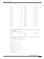
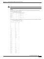
Use the show atm vc interface atm EXEC command to confirm the status of ATM virtual channels on
a specific interface:
Switch# show atm vc interface atm 7/0/0
Interface
VPI
VCI
Type
X-Interface
ATM7/0/0
0
5
PVC
ATM0/0/0
ATM7/0/0
0
16
PVC
ATM0/0/0
ATM7/0/0
0
18
PVC
ATM0/0/0
Switch#
X-VPI X-VCI
0
52
0
51
0
57
Encap
QSAAL
ILMI
PNNI
Status
UP
UP
UP
Use the show atm vc interface atm EXEC command to confirm the status of a specific ATM interface
and virtual channel:
Switch# show atm vc interface atm 7/0/0 0 16
Interface: ATM7/0/0, Type: oc3suni
VPI = 0 VCI = 16
Status: UP
Time-since-last-status-change: 2d20h
Connection-type: PVC
Cast-type: point-to-point
Packet-discard-option: enabled
Usage-Parameter-Control (UPC): pass
Wrr weight: 15
Number of OAM-configured connections: 0
OAM-configuration: disabled
OAM-states: Not-applicable
Cross-connect-interface: ATM0/0/0, Type: CPU card
Cross-connect-VPI = 0
Cross-connect-VCI = 51
Cross-connect-UPC: pass
Cross-connect OAM-configuration: disabled
Cisco 6400 Software Setup Guide
OL-1183-04
2-13
Chapter2
Basic NSP Configuration
Network Clocking
Cross-connect OAM-state: Not-applicable
Encapsulation: AAL5ILMI
Threshold Group: 6, Cells queued: 0
Rx cells: 35, Tx cells: 35
Tx Clp0:35, Tx Clp1: 0
Rx Clp0:35, Rx Clp1: 0
Rx Upc Violations:0, Rx cell drops:0
Rx pkts:16, Rx pkt drops:0
Rx connection-traffic-table-index: 3
Rx service-category: VBR-RT (Realtime Variable Bit Rate)
Rx pcr-clp01: 424
Rx scr-clp01: 424
Rx mcr-clp01: none
Rx
cdvt: 1024 (from default for interface)
Rx
mbs: 50
Tx connection-traffic-table-index: 3
Tx service-category: VBR-RT (Realtime Variable Bit Rate)
Tx pcr-clp01: 424
Tx scr-clp01: 424
Tx mcr-clp01: none
Tx
cdvt: none
Tx
mbs: 50
AAL5 statistics:
Crc Errors:0, Sar Timeouts:0, OverSizedSDUs:0
BufSzOvfl: Small:0, Medium:0, Big:0, VeryBig:0, Large:0
Switch#
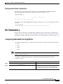
Network Clocking
This section describes the network clocking configuration of the Cisco 6400. Each port has a transmit
clock that is derived from the receive data. The transmit clock can be configured for each port in one of
the following ways:
•
Free-running—The transmit clock on the interface is derived from the port adapter's local oscillator,
if one exists. If the port adapter does not have a local oscillator, the oscillator from the NSP is used.
In this mode, the transmit clock is not synchronized with any receive clocks in the system. This
mode should be used only if synchronization is not required, as in some LAN environments.
•
Network derived—The transmit clock is derived from the highest priority configured network clock
source—the system clock (the local oscillator on the NSP), the Building Integrated Timing Supply
(BITS), or the public network.
•
Loop-timed—The transmit clock is derived from the clock source received on the same interface.
This mode can be used when connecting to a device with a very accurate clock source.
Any NLC in a Cisco 6400 chassis capable of receiving and distributing a network timing signal can
propagate that signal to any similarly capable module in the chassis. Using the network-clock-select
global configuration command, you can cause a particular port in a Cisco 6400 chassis to serve as the
primary reference source (PRS) for the entire chassis or for other devices in the networking environment.
In other words, you can designate a particular port in a Cisco 6400 chassis to serve as a “master clock”
source for distributing a single clocking signal throughout the chassis or to other network devices. This
reference signal can be distributed wherever needed in the network and can globally synchronize the
flow of constant bit rate (CBR) data.
For more information on network clocking, see the chapter “Initially Configuring the ATM Switch” in
the ATM Switch Router Software Configuration Guide.
Cisco 6400 Software Setup Guide
2-14
OL-1183-04
Chapter2
Basic NSP Configuration
Network Clocking
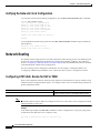
Configuring the Transmit Clock Source
By default, the interface uses a network-derived clock source. To modify how an interface derives its
transmit clock, complete the following steps beginning in global configuration mode:
Command
Purpose
Step1
Switch(config)# interface atm slot/subslot/port
Selects the interface to be configured.
Step2
Switch(config-if)# clock source {free-running |
loop-timed | network-derived}
Specifies how the interface derives its transmit clock.
Example
In the following example, ATM interface 4/0/0 is configured to derive its transmit clock from the clock
source received on the same interface:
!
interface atm 4/0/0
clock source loop-timed
!
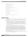
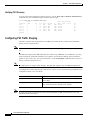
Configuring Network Clock Priorities and Sources
You can configure multiple network clock sources and assign priority values to each source. The system
uses the highest priority clock source available as the “network-derived” clock source for the transmit
clock.
To configure the network clock priorities and sources, use the following command in global
configuration mode:
Command
Purpose
Switch(config)# network-clock-select priority
{system | atm slot/subslot/port}
Configures a network clock priority and source. Priority1
values range from 1 (highest) to 4 (lowest). System selects
the local oscillator on the NSP.
1.
Priorities 1 to 4 initially default to “no clock.” Priority 5 is a pseudo-priority that defaults to “system clock” and is not configurable. If priorities 1 to 4
are not configured, the priority 5 system (NSP) clock is used as the derived clock.
Example
In the following example, interface ATM 2/0/0 is configured as the highest priority network clock
source:
!
network-clock-select 1 atm 2/0/0
network-clock-select 2 atm 2/0/1
network-clock-select 3 atm 1/0/0
!
interface atm 1/0/0
clock source network-derived
!
As long as interface ATM 2/0/0 is available, all transmit clocking on ATM 1/0/0 will be derived from
ATM 2/0/0. If the ATM 2/0/0 clock source fails, the system will attempt to use the next highest priority
clock source, which in this case is ATM 2/0/1.
Cisco 6400 Software Setup Guide
OL-1183-04
2-15
Chapter2
Basic NSP Configuration
Network Clocking
Configuring Network Clock Revertive Behavior
Revertive behavior enables the network clock to automatically switch to the highest priority clock source
available. When a clock failure is detected, the next highest priority clock source is selected. If revertive
behavior is not configured, the clock source will not switch back even when the failed (but higher
priority) clock source is restored.
To enable network clock revertive behavior on the NSP, use the following command in global
configuration mode:
Command
Purpose
Switch(config)# network-clock-select revertive
Configures revertive behavior on the network
clock.
Example
In the following example, the network clock reverts to the highest priority clock source after a failure:
!
network-clock-select
network-clock-select
network-clock-select
network-clock-select
!
1 atm 2/0/0
2 atm 2/0/1
3 atm 1/0/0
revertive
Configuring Building Integrated Timing Supply Network Clocking
BITS network clocking enables the Cisco 6400 to derive network timing from the central office (CO)
BITS as well as from a clock recovered from a specified NLC interface. The Cisco 6400 can also
distribute the BITS network timing with stratum level 3 accuracy to other network devices.
The BITS Network Clocking feature requires the NSP with stratum 3/BITS (NSP-S3B) module.
Figure2-2 shows the NSP-S3B module faceplate.
Figure2-2
NSP-S3B Module Faceplate
In addition to enabling the BITS Network Clocking feature, the NSP-S3B allows the Cisco 6400 to serve
as a stratum 3 network clock source for other network devices. When no external clock source is
available, the NSP-S3B provides stratum level 3 internal timing on the Cisco 6400. Otherwise, the
NSP-S3B is identical to the default NSP.
For information about installing the NSP-S3B, see the Cisco 6400 UAC Hardware Installation and
Maintenance Guide .To see if the NSP-S3B is installed in the Cisco 6400 chassis, use the
showhardware EXEC command. The output will contain an “NSP-NC” controller type (Ctrlr-Type)
for each NSP-S3B in the chassis .
Cisco 6400 Software Setup Guide
2-16
OL-1183-04
Chapter2
Basic NSP Configuration
Network Clocking
NSP# show hardware
6400 named NSP, Date:16:59:29 UTC Wed Feb 28 2001
Feature Card's FPGA Download Version:0
Slot
----1/0
2/0
3/0
4/0
5/0
6/0
7/0
8/0
5/1
0A/PC
0A/FC
0A/SC
0A/NC
0B/PC
0B/FC
0B/SC
0B/NC
Ctrlr-Type
-----------NRP2
622SM NLC
NRP2
NRP2
155SM NLC
NRP2
622SM NLC
NRP2
155SM NLC
NSP-PC
FC-PFQ
NSP-SC
NSP-NC
NSP-PC
FC-PFQ
NSP-SC
NSP-NC
Part No. Rev
---------- -00-0000-00 01
73-3868-02 A0
UNKNOWN
01
UNKNOWN
01
73-2892-03 01
UNKNOWN
01
73-3868-02 A0
00-0000-00 01
73-2892-02 02
73-2996-02 02
73-2281-04 A0
73-2997-02 07
73-3243-01 00
73-2996-02 02
73-2281-04 A0
73-2997-02 07
73-3243-01 00
Ser No
-------00000000
16097980
UNKNOWN
UNKNOWN
09156394
UNKNOWN
14327654
00000000
09690988
09702853
09694957
12345678
14012804
09702826
09694884
12345678
14012806
Mfg Date
--------Jan 01 00
Feb 04 00
Jul 00 00
Jul 00 00
Aug 28 98
Jul 00 00
Oct 15 99
Jan 01 00
Jul 20 98
Sep 01 98
Aug 20 98
Aug 27 98
Jul 01 99
Sep 01 98
Aug 06 98
Aug 28 98
Jul 01 99
RMA No. Hw Vrs Tst EEP
-------- ------- --- --00-00-00
1.0
0
2
00-00-00
1.0
0
2
00-00-00
1.0
0
2
00-00-00
1.0
0
2
00-00-00
3.1
0 FF
00-00-00
1.0
0
2
00-00-00
1.0
0
2
00-00-00
1.0
0
2
00-00-00
1.0
0
2
00-00-00
1.0
0
2
00-00-00
4.1
0
2
00-00-00
1.0
0
2
00-00-00
1.0
0
2
00-00-00
1.0
0
2
00-00-00
4.1
0
2
00-00-00
1.0
0
2
00-00-00
1.0
0
2
Primary NSP:Slot 0A
DS1201 Backplane EEPROM:
Model Ver. Serial MAC-Address MAC-Size
------- ---- -------- ------------ -------C6400
2
10036118 00107BB9B600
128
RMA
--0
RMA-Number
---------0
MFG-Date
----------Aug 26 1998
NSP#
Note
To derive network clocking from the CO BITS, the BITS input must be less than 9.2 parts per million
(ppm) off center. Otherwise, the NSP-S3B declares the clock source invalid.
To derive network clocking from the BITS signal, use the following commands on the NSP-S3B in
global configuration mode:
Command
Purpose
Step1
Switch(config)# network-clock-select priority BITS
Selects the BITS network clock and specifies the
priority.
Step2
Switch(config)# network-clock-select BITS {T1|E1}
Specifies BITS port as either T1 or E1.
Example
In the following example, the CO BITS is selected as the priority 1 network clock source. Lower priority
clock sources are also configured for redundancy, and revertive behavior is selected.
!
network-clock-select
network-clock-select
network-clock-select
network-clock-select
network-clock-select
network-clock-select
!
revertive
bits e1
1 bits
2 ATM1/0/0
3 ATM5/0/0
4 ATM7/0/0
Cisco 6400 Software Setup Guide
OL-1183-04
2-17
Chapter2
Basic NSP Configuration
Network Routing
Verifying the Network Clock Configuration
To verify the switch network clocking configuration, use the show network-clocks EXEC command:
Switch# show network-clocks
clock configuration is NON-Revertive
Priority 1 clock source: ATM2/0/0 up
Priority 2 clock source: ATM7/0/0 down
Priority 3 clock source: ATM6/0/0 up
Priority 4 clock source: unconfigured
Priority 5 clock source: system
Current clock source: ATM2/0/0, priority: 1
Switch#
To verify BITS network clocking, make sure the show network-clocks command output includes the
following lines:
Priority 1 clock source: bits up
Current clock source: bits, priority: 1
Network Routing
The default software image for the Cisco 6400 contains the PNNI routing protocol. The PNNI protocol
provides the route dissemination mechanism for complete plug-and-play capability. The following
section, “ Configuring ATM Static Routes for IISP or PNNI,” describes modifications that can be made
to the default PNNI or IISP routing configurations.
For more routing protocol configuration information, see the chapters “Configuring ILMI” and
“Configuring ATM Routing and PNNI” in the ATM Switch Router Software Configuration Guide .
Configuring ATM Static Routes for IISP or PNNI
Static route configuration allows ATM call setup requests to be forwarded on a specific interface if the
addresses match a configured address prefix. To configure a static route, use the following command in
global configuration mode:
Command
Purpose
Switch(config)# atm route addr-prefx atm slot/subslot/port
Specifies a static route to a reachable address prefix.
Note
An interface must be UNI or IISP to be configured with a static route. Static routes configured as PNNI
interfaces default to down state.
Example
In the following example, the atm route command is used to configure the 13-byte peer group prefix
47.0091.8100.567.0000.0ca7.ce01 at interface 3/0/0:
!
atm route 47.0091.8100.567.0000.0ca7.ce01 atm 3/0/0
!
Cisco 6400 Software Setup Guide
2-18
OL-1183-04
Chapter2
Basic NSP Configuration
NRP-2 and NRP-2SV Support
Verifying ATM Static Routes for IISP or PNNI
To verify successful configuration of an ATM static route, use the show atm route and
showatmpnnitopology EXEC commands.
NRP-2 and NRP-2SV Support
The NSP provides the following functions for the NRP-2 and NRP-2SV:
Note
•
Image and File Storage , page 2-19
•
System Logging, page 2-21
•
Console and Telnet Access, page 2-21
•
SNMPv3 Proxy Forwarder, page 2-22
•
Troubleshooting and Monitoring the NRP-2, page 2-22
Unless a clear distinction is made, all references to the NRP-2 also apply to the NRP-2SV.
Image and File Storage
The NRP-2 has no local image or file storage. The NSP stores the following NRP-2 files on the Personal
Computer Memory Card International Association (PCMCIA) disk:
Note
•
NRP-2 images
•
NRP-2 system configuration files
•
NRP-2 ROM state information
•
Crash information
A PCMCIA disk must be in NSP disk slot 0.
Whenever the NSP reloads, a PCMCIA disk is inserted, or the PCMCIA disk is formatted, the NSP
checks for the following directories on the PCMCIA disk and automatically creates those that are
missing:
•
images—One directory for storing NRP-2 images.
•
slot1, slot2,..., slot8—Eight directories for storing files for specific NRP-2 slots. Each slot directory
normally contains the following files when an NRP-2 is present in the slot:
– Startup configuration file (nrp2-startup-config)
– ROMMON variables (nrp2_rommon_nv.0)
– Crash information (crashinfo_yyyymmdd-hhmmss )
Note
Do not remove the image and slot directories. Also, make sure that you understand the consequences
before you delete any files in these directories.
Cisco 6400 Software Setup Guide
OL-1183-04
2-19
Chapter2
Basic NSP Configuration
NRP-2 and NRP-2SV Support
You can create additional directories on the PCMCIA disk with the mkdir command. See the “Cisco
IOS File Management” chapter in the Cisco IOS Configuration Fundamentals Configuration Guide.
Configuring NRP-2 Image Management on the NSP
The NSP controls and manages the NRP-2 image download process. Cisco recommends that you store
all NRP-2 images on the NSP PCMCIA disk, but you can also store NRP-2 images on a TFTP, FTP, or
rcp server.
You can also assign priority values to each NRP-2 image and path. This allows you to enter multiple
hw-module (image ) commands in any order, while still having control over how they are executed.
For each NRP-2 in your Cisco 6400 system, enter the following command on the NSP in global
configuration mode:
Command
Purpose
Switch(config)# hw-module slot slot
image image-path priority priority
Assigns an image filename and path to the specified NRP-2 processor in
the selected slot. Priority range is from 1 (highest) to 4 (lowest).
Without the hw-module (image) command in the NSP configuration, the NRP-2 attempts to load the
default image (c6400r2sp-g4p5-mz) from the disk0:/images/ directory.
Timesaver
If you do not use all the priority values for NRP-2 images, leave priority 1 free for new or temporary
images. Otherwise, you will have to adjust the priority levels of the other images for your NRP-2 to
accommodate the new image.
Example
In the following example, the NRP-2 in slot 2 of the Cisco 6400 chassis has three images assigned with
different priorities, while the NRP-2 in slot 3 has only one image assigned:
!
hw-module
hw-module
hw-module
hw-module
!
slot
slot
slot
slot
2
2
2
3
image
image
image
image
c6400r2sp-g4p5-mz.121-4.DC.bin priority 2
tftp://10.1.1.1/c6400r2sp-g4p5-mz.121-4.DC.bin priority 3
disk0:MyDir/c6400r2sp-g4p5-mz.121-4.DC.bin priority 4
c6400r2sp-g4p5-mz.121-4.DC.bin priority 2
In the first and last entries of the example, the system tries to find the images (with no specified path) in
the disk0:/images/ directory.
Cisco 6400 Software Setup Guide
2-20
OL-1183-04
Chapter2
Basic NSP Configuration
NRP-2 and NRP-2SV Support
Changing the NRP-2 Configuration Register Setting
The configuration register defaults to the correct setting for normal operation. You should not change
this setting unless you want to enable the break sequence or switch ROMMON devices.
To change the NRP-2 configuration register setting, enter the following command in global
configuration mode:
Command
Purpose
1
Switch(config)# hw-module slot slot config-register value
1.
Changes the configuration register setting of
the NRP-2 in the specified slot.
For specific configuration register values, see “hw-module” in the Cisco 6400 Command Reference.
Example
In the following example, an NRP-2 in slot 3 is set to boot to ROMMON, where ROMMON runs from
the image found in BootFROM1. If you enter the boot ROMMON command, the NRP-2 loads the
specified image from the disk0:/images/ directory.
hw-module slot 3 config-register 0x2100
hw-module slot 3 image c6400r2sp-g4p5-mz.121-4.DC.bin priority 2
System Logging
By default, each system log message created by the NRP-2 appears on the NSP as a local message, and
the message is labeled with the slot number of the NRP-2 that created the message. If console logging
is enabled, each system log message also appears on the NRP-2 console.
For more information on NRP-2 console and system logging, see the “Using NRP-2 Console and System
Logging” section on page3-15.
Disabling NRP-2 System Logging on the NSP
To disable the appearance of NRP-2 system log messages on the NSP, use the following EXEC
command:
Command
Purpose
Switch# no logging console
Stops NRP-2 system log messages from appearing on the NSP.
Console and Telnet Access
The NSP has been equipped with an internal communication server to access the NRP-2 console lines.
The NSP also has alias commands for using Telnet to connect to the NRP-2. For more information, see
the “Methods Available for Configuring the NRP-2 ” section on page3-9.
Cisco 6400 Software Setup Guide
OL-1183-04
2-21
Chapter2
Basic NSP Configuration
NRP-2 and NRP-2SV Support
SNMPv3 Proxy Forwarder
The NSP and NRP-2 support SNMPv1, SNMPv2c, and SNMPv3. The NSP can use the SNMPv3 Proxy
Forwarder feature to:
•
Route the SNMPv3 messages destined for NRP-2
•
Forward NRP-2 traps to the Network Element Manager
For general information on using SNMP, see the “Configuring Simple Network Management Protocol
(SNMP)” section i n the “System Management” part of the Cisco IOS Configuration Fundamentals
Configuration Guide. For information on the Proxy Forwarder feature, see the “Using the NSP as the
SNMPv3 Proxy Forwarder for the NRP-2” section on page6-1.
Troubleshooting and Monitoring the NRP-2
Use the following NSP commands to troubleshoot or monitor the NRP-2:
Command
Purpose
Switch# clear line slot
Clears NRP-2 console connections from the NSP.
Switch> who
Displays the console and Telnet connections.
Switch> show line [line-type ] number
Displays the parameters of a terminal line.
Switch# debug config-download
Displays debug messages for the configuration download protocol.
Switch# debug image-download [tftp]
Displays debug messages for the image download protocol.
With optional tftp keyword, displays TFTP monitoring information as
well.
Displays debug messages for traffic flowing on the NRP-2 PAM mailbox
serial interface.
Switch# debug pmbox
More troubleshooting and monitoring commands can be entered on the NRP-2. See the
“Troubleshooting and Monitoring the NRP-2” section on page3-16.
Examples
In the following example, the who EXEC command is used to identify the connection from the NSP to
the NRP-2 console, and the clear privileged EXEC command is used to close the NRP-2 console session:
NSP# who
Line
*
0 con 0
6 tty 6
18 vty 0
Interface
User
User
NSP# clear line 6
[confirm]
[OK]
NSP# who
Line
User
* 0 con 0
18 vty 0
Host(s)
idle
incoming
10.6.0.2
Mode
Host(s)
idle
10.6.0.2
Idle
00:00:00
00:03:03
00:02:59
Location
20.1.0.254
20.1.5.1
Idle Peer Address
Idle
00:00:00
00:03:07
Location
20.1.5.1
Cisco 6400 Software Setup Guide
2-22
OL-1183-04
Chapter2
Basic NSP Configuration
Storing the NSP Configuration
Interface
User
Mode
Idle Peer Address
NSP#
In the following example, the show line EXEC command is entered on the NSP to look at the console
connection to the NRP-2:
NSP# show line 6
Tty Typ
Tx/Rx
*
6 TTY
0/0
-
A Modem
-
Roty AccO AccI
-
Uses
7
Noise
0
Overruns
0/0
Int
-
Line 6, Location:"", Type:"XTERM"
Length:24 lines, Width:80 columns
Status:Ready, Connected, Active
Capabilities:EXEC Suppressed, Software Flowcontrol In,
Software Flowcontrol Out
Modem state:Ready
Modem hardware state:CTS DSR DTR RTS
Special Chars:Escape Hold Stop Start Disconnect Activation
^^x
none
^S
^Q
none
Timeouts:
Idle EXEC
Idle Session
Modem Answer Session
Dispatch
00:10:00
never
none
not set
Idle Session Disconnect Warning
never
Login-sequence User Response
00:00:30
Autoselect Initial Wait
not set
Modem type is unknown.
Session limit is not set.
Time since activation:00:03:26
Editing is enabled.
History is enabled, history size is 10.
DNS resolution in show commands is enabled
Full user help is disabled
Allowed transports are telnet. Preferred is telnet.
No output characters are padded
No special data dispatching characters
NSP#
Storing the NSP Configuration
When autoconfiguration and any manual configurations are complete, you should copy the configuration
into nonvolatile random-access memory (NVRAM). If you reload the NSP before you save the
configuration in NVRAM, you will lose all manual configuration changes.
To save your running configuration as the startup configuration in NVRAM, use the
copysystem:running-config EXEC command:
Switch# copy system:running-config nvram:startup-config
Building configuration...
[OK]
Switch#
Verifying the NSP Configuration
To view the running configuration, use the more system:running-config EXEC command.
To view the startup configuration in NVRAM, use the more nvram:startup-config EXEC command.
Cisco 6400 Software Setup Guide
OL-1183-04
2-23
Chapter2
Basic NSP Configuration
Using the NSP File Systems and Memory Devices
Using the NSP File Systems and Memory Devices
File systems on the NSP include read-only memory (NVRAM, or system), Flash memory (such as
PCMCIA disks 0 and 1, and boot flash), and remote file systems (such as TFTP or rcp servers). Use the
showfilesystems privileged EXEC command to display the valid file systems on your NSP:
Switch# show file systems
File Systems:
Size(b)
20819968
109760512
7602176
520184
20819968
109760512
5242880
5242880
*
Free(b)
10022912
109760512
2363376
515975
10022912
109760512
0
5242880
Type
flash
flash
flash
flash
flash
nvram
flash
flash
flash
flash
flash
opaque
opaque
network
nvram
flash
flash
network
network
opaque
opaque
Flags
rw
rw
rw
rw
rw
rw
rw
rw
rw
rw
rw
rw
rw
rw
rw
rw
rw
rw
rw
ro
ro
Prefixes
sec-slot0:
sec-slot1:
sec-disk0:
sec-disk1:
sec-bootflash:
sec-nvram:
disk0:flash:
disk1:
slot0:
slot1:
bootflash:
null:
system:
tftp:
nvram:
mir-disk0:
mir-disk1
rcp:
ftp:
atm-acct-ready:
atm-acct-active:
Switch#
Use the dir privileged EXEC command to show the contents of a file system. Remember to include the
trailing colon in the name of the file system:
Switch# dir bootflash:
Directory of bootflash:/
1
-rw-
3728308
Jan 01 2000 00:02:44
c6400s-wp-mz.120-5.DB
7602176 bytes total (3873740 bytes free)
Switch#
If your Cisco 6400 system contains an additional (secondary) NSP, use the dir command with file
systems that begin with sec- to show file systems on the secondary NSP. For example, dir sec-nvram:
will show the contents of the NVRAM on the secondary NSP.
Caution
Do not use slot0: and slot1: to refer to the NSP PCMCIA disks. Use disk0: and disk1: instead.
Cisco 6400 Software Setup Guide
2-24
OL-1183-04
Chapter2
Basic NSP Configuration
Using the NSP File Systems and Memory Devices
Example—Disk0: versus Slot0:
Switch# dir disk0:
Directory of disk0:/
3
157
376
-rwdrw-rw-
628224
0
2134
Jan 01 2000 00:08:55
Jan 01 2000 00:11:01
Jan 05 2000 22:05:27
c6400s-html.tar.120-4.DB
nsp-html
startup.config
109760512 bytes total (108228608 bytes free)
Switch# dir slot0:
%Error opening slot0:/ (Device not ready)
Switch#
In Cisco IOS Release 12.1(5)DB, the PCMCIA Disk Mirroring feature introduced the mir-disk0: and
mir-disk1: labels. These labels enable you to perform any integrated file system (IFS) operation (such as
copy, rename, and delete) on the same file on both the primary and secondary PCMCIA disks. For more
information, see the “Performing Mirrored IFS Operations” section on page5-11.
Cisco 6400 Software Setup Guide
OL-1183-04
2-25
Chapter2
Basic NSP Configuration
Using the NSP File Systems and Memory Devices
Cisco 6400 Software Setup Guide
2-26
OL-1183-04
C H A P T E R
3
Basic NRP Configuration
This chapter describes how to perform a basic configuration for the node route processors (NRP-1,
NRP-2, and NRP-2SV). The Cisco6400 can contain multiple NRP modules, configured to operate
independently or as 1+1 redundant pairs (NRP-1 only at this time). This chapter contains the following
sections:
•
NRP-1 Configuration, page 3-1
•
NRP-2 and NRP-2SV Configuration, page 3-7
•
Transferring an NRP-1 Configuration to an NRP-2 or NRP-2SV, page 3-20
•
Permanent Virtual Circuits , page 3-20
For information on differences among the NRP types, see the release notes for your specific software
images. Also see Table1-1 on page1-4.
NRP-1 Configuration
This section describes configuration information specific to the NRP-1, including:
•
Methods Available for Configuring the NRP-1 , page 3-1
•
Initial NRP-1 Configuration, page 3-2
•
Segmentation and Reassembly Buffer Management , page 3-5
•
Using the NRP-1 File Systems and Memory Devices, page 3-6
Methods Available for Configuring the NRP-1
The following methods are available for configuring the NRP-1:
•
From a local console or workstation—Connect to the console port of the NRP-1.
•
From a remote console or workstation—Initiate a Telnet connection to the NRP-1 over the NME
interface.
•
From the Cisco 6400 Service Connection Manager—See theCisco 6400 SCM documentation.
For general information on basic Cisco IOS configuration, see the Cisco IOS Configuration
Fundamentals Configuration Guide .
Cisco 6400 Software Setup Guide
OL-1183-04
3-1
Chapter3
Basic NRP Configuration
NRP-1 Configuration
Note
If your Telnet station or Simple Network Management Protocol (SNMP) network management
workstation and the Cisco 6400 are on different networks, you must either use Dynamic Host
Configuration Protocol (DHCP) to provide a default route, or add a static routing table entry to the
routing table. To assign a static IP route, use the ip route global configuration command.
Initial NRP-1 Configuration
An NRP-1 running Cisco IOS Release 12.0(5)DC or later comes preinstalled with a default configuration
and does not require initial configuration.
The following sections describe how to configure the NRP-1 for the first time:
•
Using DHCP, page 3-2
•
Checking the Software Release Version and Choosing the Configuration Method, page 3-2
•
Configuring the NRP-1 , page 3-3
•
Verifying the Initial NRP-1 Configuration, page 3-4
Using DHCP
If you plan to configure a DHCP server to inform the NRP-1 of its IP address and mask, write down the
Media Access Control (MAC) address of the server’s Ethernet port.
Optionally, take note of a default gateway address and static routes to the DHCP server.
Note
The Cisco 6400 performs a DHCP request only if the NME interface is configured with the ipaddress
negotiated interface configuration command.
DHCP is the default IP assignment protocol for a new NRP-1, or for an NRP-1 that has had its
configuration file cleared by means of the erase nvram:startup-config command. For DHCP, an
Ethernet IP address, subnet mask, and the default route are retrieved from the DHCP server for any
interface set with the ip address negotiated command. To configure DHCP, add an entry in the DHCP
database using the instructions that came with your DHCP server.
Checking the Software Release Version and Choosing the Configuration Method
Complete the following steps to check the software release version and prepare for initial configuration:
Step 1
Connect a console terminal or a terminal server to the NRP-1 console port on the NRP-1 faceplate.
After the NRP-1 autoboots, the following information appears to verify that the router has booted
successfully.
Take note of the software release version included in the display. For information on upgrading to a
higher release version, see Upgrading Software on the Cisco 6400.
Restricted Rights Legend
Use, duplication, or disclosure by the Government is
subject to restrictions as set forth in subparagraph
(c) of the Commercial Computer Software - Restricted
Cisco 6400 Software Setup Guide
3-2
OL-1183-04
Chapter3
Basic NRP Configuration
NRP-1 Configuration
Rights clause at FAR sec. 52.227-19 and subparagraph
(c) (1) (ii) of the Rights in Technical Data and Computer
Software clause at DFARS sec. 252.227-7013.
Cisco Systems, Inc.
170 West Tasman Drive
San Jose, California 95134-1706
Cisco Internetwork Operating System Software
IOS (tm) C6400R Software (C6400R-G4P5-M), Version 12.3
Copyright (c) 1986-2002 by cisco Systems, Inc.
Compiled Thu 14-Oct-02 2314 by jdoe
Image text-base 0x60008960, data-base 0x60D2A000
Cisco NRP (NRP1) processor with 94208K/36864K bytes of memory.
R5000 CPU at 200Mhz, Implementation 35, Rev 2.1, 1024KB L2 Cache
Last reset from BOOTFLASH
X.25 software, Version 3.0.0.
Bridging software.
2 Ethernet/IEEE 802.3 interface(s)
1 FastEthernet/IEEE 802.3 interface(s)
1 ATM network interface(s)
125K bytes of non-volatile configuration memory.
4096K bytes of Boot flash ROM (Sector size 256K).
8192K bytes of Flash SIMM (Sector size 256K).
Press RETURN to get started!
Step 2
Press Return. After a few seconds, the user EXEC prompt
command to enter privileged EXEC mode:
Router>
appears. Use the enable EXEC
Router> enable
Router#
The prompt changes to the privileged EXEC prompt, from which you can manually configure the
NRP-1. Proceed to the “Configuring the NRP-1” section on page3-3.
Configuring the NRP-1
To perform an initial basic NRP-1 configuration, complete the following steps:
Step 1
Use the configure terminal privileged EXEC command to enter global configuration mode:
Router# configure terminal
Enter configuration commands, one per line. End with CNTL/Z.
Router(config)#
The prompt changes to the global configuration mode prompt.
Step 2
Enter the enable secret (which is a secure encrypted password) and the enable password (which is a
nonencrypted password). The passwords should be different for maximum security. The following
example sets the enable secret to “walnut” and the enable password to “pecan”:
Router(config)# enable secret walnut
Router(config)# enable password pecan
Cisco 6400 Software Setup Guide
OL-1183-04
3-3
Chapter3
Basic NRP Configuration
NRP-1 Configuration
An enable secret can contain from 1 to 25 uppercase and lowercase alphanumeric characters; an enable
password or virtual terminal password can contain any number of uppercase and lowercase
alphanumeric characters. In all cases, a number cannot be the first character. Spaces are also valid
password characters. Leading spaces are ignored; trailing spaces are recognized.
Step 3
Enter a host name for the NRP-1. The default host name is
prompt.
Router.
The host name appears in the CLI
Router(config)# hostname NRP-1
NRP-1(config)#
Step 4
If you are upgrading the NRP-1 from an earlier software version to Cisco IOS Release 12.0(5)DC or
later, you can configure the NRP-1 to support network management Ethernet (NME) consolidation with
the NSP. Complete the following steps to enable NME consolidation:
a.
Enter interface configuration mode for Ethernet 0/0/0:
NRP-1(config)# interface ethernet 0/0/0
b.
Remove any IP address and subnet mask associated with Ethernet 0/0/0:
NRP-1(config-if)# no ip address
c.
Enter interface configuration mode for Ethernet 0/0/1:
NRP-1(config-if)# interface ethernet 0/0/1
d.
Choose one of the following methods of assigning the IP address to Ethernet 0/0/1:
•
Enable the DHCP server to obtain an IP address for Ethernet 0/0/1:
NRP-1(config-if)# ip address negotiated
or
•
Assign a static IP address to Ethernet 0/0/1:
NRP-1(config-if)# ip address 172.26.94.158 255.255.255.0
e.
Return to privileged EXEC mode:
NRP-1(config-if)# ^Z
Step 5
Store the running configuration in NVRAM as the startup configuration:
NRP-1# copy system:running-config nvram:startup-config
Destination filename [nrp-startup-config]? <cr>
847927 bytes copied in 280.48 secs (3028 bytes/sec)
NRP-1#
When the NRP-1 reloads, it runs the startup configuration. If you do not perform Step 5, your
configuration changes will be lost the next time you reload the NRP-1.
Your NRP-1 is now minimally configured and will reload with the configuration you have entered. To
see a list of the configuration commands available to you, enter ? at the prompt or press the help key
while you are in configuration mode.
Verifying the Initial NRP-1 Configuration
To check the running configuration, use the more system:running-config EXEC command.
To check the startup configuration in NVRAM, use the more nvram:startup-config EXEC command.
Cisco 6400 Software Setup Guide
3-4
OL-1183-04
Chapter3
Basic NRP Configuration
NRP-1 Configuration
Segmentation and Reassembly Buffer Management
In Cisco IOS Release 12.1(1)DC, the following segmentation and reassembly (SAR) buffer management
enhancements were introduced:
•
Reduced Segmentation Buffer Size—Prior to this release, the default size of the PVC segmentation
buffer was 256 packets. This meant that each PVC could queue up to 256 packets to be segmented
and sent. Now the default size is 32 packets, and a new command allows you to manually change
the segmentation buffer size.
•
Increased Input/Output Memory Size—Prior to this release, the default input/output (I/O) memory
size was 16 MB for NRP-1s with 64 MB or 128 MB DRAM. Now the default I/O memory size is
18 MB for an NRP-1 with 64 MB DRAM, and 36MB for an NRP-1 with 128 MB DRAM. You can
also manually set the I/O memory size with an environment variable under ROM monitor
(ROMMON).
•
Reserved Segmentation Buffer Slot for High-Priority Packets—For each PVC, a segmentation
buffer slot is reserved for high-priority packets.
These SAR buffer management enhancements reduce the amount of memory resources that can be held
by congested PVCs. This prevents a small group of congested PVCs from using all available memory
resources and adversely affecting the performance of other PVCs. The enhancements also improve
high-priority packet transmission. With a segmentation buffer slot reserved for high-priority packets,
each PVC accommodates high-priority packets even when the segmentation buffer is full.
Note
Because of process memory usage, setting the I/O memory size to a larger value might reduce the
number of sessions that your NRP-1 can handle.
Setting the Segmentation Buffer Size
Caution
Entering the atm vc tx command can cause service disruption. Only enter this command during
maintenance windows.
To manually set the size of all PVC segmentation buffers, complete the following steps beginning in
global configuration mode:
Command
Purpose
Step1
Router(config)# interface atm 0/0/0
Specifies the ATM interface.
Step2
Router(config-if-atm-vc)# atm vc tx queue-depth
Sets the maximum number of packets in the PVC
segmentation buffers.
Example
In the following example, the PVC segmentation buffer size is set to 64 packets.
!
interface atm 0/0/0
atm vc tx 64
!
Cisco 6400 Software Setup Guide
OL-1183-04
3-5
Chapter3
Basic NRP Configuration
NRP-1 Configuration
Verifying the PVC Segmentation Buffer Size
To verify successful configuration of the segmentation buffer size, use the show running-config EXEC
command.
Setting the I/O Memory Size
To manually set the size of I/O memory, enter the following command in ROMMON mode:
Command
Purpose
Rommon> IOMEM=size
Sets the size, in MB, of I/O memory. Allowed values depend on the
amount of DRAM on your NRP, and they are listed in Table3-1 .
Table3-1
Note
Allowed Values of I/O Memory on the Cisco 6400 NRP-1
Main Memory on NRP-1
Allowed I/O Memory Range
Default IOMEM Setting
64 MB DRAM
18 MB to 24 MB
18 MB
128 MB DRAM
18 MB to 60 MB
36 MB
IOMEM entries must be an even number. If you enter an odd number, the NRP-1 will round it down to
an even number. If you enter a number outside of the allowed I/O memory range, the NRP-1 will use the
default IOMEM setting. You can also enter unset IOMEM in ROMMON to return to the default setting.
Example
In the following example, the I/O memory size is set to 20 MB.
Rommon> IOMEM=20
Verifying the I/O Memory Size
To verify that you successfully set the I/O memory size, use the show memory EXEC command. The
following example shows an NRP-1 with an I/O memory size of 16 MB:
Router# show memory
Head
Processor 60E27540
I/O
3000000
Total(b)
35490496
16777216
Used(b)
5517076
6006460
Free(b)
29973420
10770756
Lowest(b)
14919296
5385388
Largest(b)
29838876
10770108
Using the NRP-1 File Systems and Memory Devices
File systems on the NRP-1 include read-only memory (system), read-write memory (NVRAM), Flash
memory (boot flash), and remote file systems (such as TFTP, FTP, and rcp servers). Use the
showfilesystems privileged EXEC command to display the valid file systems on your NRP-1:
Router# show file systems
File Systems:
Size(b)
-
Free(b)
-
Type
flash
Flags
rw
Prefixes
sec-flash:
Cisco 6400 Software Setup Guide
3-6
OL-1183-04
Chapter3
Basic NRP Configuration
NRP-2 and NRP-2SV Configuration
3407872
7602176
129016
-
*
249884
3905620
128049
-
flash
nvram
flash
flash
opaque
opaque
network
nvram
opaque
network
network
rw
rw
rw
rw
rw
rw
rw
rw
wo
rw
rw
sec-bootflash:
sec-nvram:
bootflash:
flash:
null:
system:
tftp:
nvram:
lex:
rcp:
ftp:
Router#
Use the dir command to show the contents of a file system. Remember to include the trailing colon in
the name of the file system:
Router# dir bootflash:
Directory of bootflash:/
1
-rw-
3157860
Jul 15 2000 03:45:14
c6400r-boot-mz.120-5.DC
3407872 bytes total (249884 bytes free)
Router#
If your Cisco 6400 system is configured with redundant NRP-1s, use the dir command with file systems
that begin with sec- to show file systems on the secondary (redundant) NRP-1. For example,
dirsec-nvram: will show the contents of the NVRAM on the secondary NRP-1.
NRP-2 and NRP-2SV Configuration
This section describes information specific to the NRP-2 and NRP-2SV. This section includes the
following topics:
Note
•
Restrictions, page 3-8
•
Prerequisites, page 3-8
•
Methods Available for Configuring the NRP-2 , page 3-9
•
Matching the MTU Size of the NRP-2 and Its Network Neighbors, page 3-11
•
Modifying VPI and VCI Ranges on the NRP-2, page 3-13
•
Saving the NRP-2 Startup Configuration, page 3-15
•
Using NRP-2 Console and System Logging, page 3-15
•
Troubleshooting and Monitoring the NRP-2, page 3-16
Unless a clear distinction is made, all references to the NRP-2 also apply to the NRP-2SV.
Cisco 6400 Software Setup Guide
OL-1183-04
3-7
Chapter3
Basic NRP Configuration
NRP-2 and NRP-2SV Configuration
Restrictions
For a complete list of restrictions, limitations, and supported features, see the release notes for the
software version running on your NRP-2.
This section describes the following limitations:
•
Soft PVCs Between the NRP-2 and NSP
•
Maximum Transmission Unit
•
VPI and VCI Limitation
Soft PVCs Between the NRP-2 and NSP
Soft PVCs between the NRP-2 and NSP are not supported.
Maximum Transmission Unit
The maximum transmission unit (MTU) of the NRP-2 ATM interface to the backplane is 1900 bytes.
Any incoming ATM packet larger than 1900 bytes is dropped by the NRP-2. To make sure that no
incoming packets are larger than the NRP-2 MTU, see the “Matching the MTU Size of the NRP-2 and
Its Network Neighbors” section on page3-11.
VPI and VCI Limitation
Note
For Cisco IOS Releases 12.2(4)B, 12.2(13)T, 12.3, and later releases, the NRP-2SV supports 16 bits of
VPI and VCI values. The 14-bit VPI and VCI limitation described in this section applies to the NRP-2
and to the NRP-2SV running CiscoIOS Release 12.2(2)B and earlier releases.
VPI and VCI values on the NRP-2 must share 14 bits. By default, VPI values are limited to 4 bits (0–15),
and VCI values are limited to 10 bits (0–1023). You can change the VPI and VCI ranges, but together
the VPI and VCI values cannot exceed 14 bits. To change the allowed VPI and VCI values, see the
“Modifying VPI and VCI Ranges on the NRP-2” section on page3-13 .
Prerequisites
•
A Personal Computer Memory Card International Association (PCMCIA) disk must be in NSP disk
slot 0. If using redundant NSPs, make sure that the secondary NSP also has a PCMCIA disk in disk
slot 0.
•
Use the same release versions for the system images on the NRP-2 and the NSP.
•
Copy the NRP-2 image to a TFTP server on the local management network or to the PCMCIA disk
in NSP disk slot 0.
•
Complete the NSP configuration tasks in the “NRP-2 and NRP-2SV Support” section on page2-19.
Cisco 6400 Software Setup Guide
3-8
OL-1183-04
Chapter3
Basic NRP Configuration
NRP-2 and NRP-2SV Configuration
Methods Available for Configuring the NRP-2
There are two methods available for accessing the NRP-2:
•
Accessing the NRP-2 Console Through the NSP
•
Using Telnet to Connect to the NRP-2 from the NSP
You can also configure the NRP-2 with the Cisco 6400 Service Connection Manager, Release 2.2(1) and
later. For more information, see theCisco 6400 SCM documentation.
Accessing the NRP-2 Console Through the NSP
The NSP is equipped with an internal communication server for accessing the NRP-2 console line. To
access the NRP-2 console line, use Telnet to connect to the NSP as a communication server, using the
port numbers shown in Table3-2 to select the NRP-2.
Table3-2
Internal NSP Communication Server Port-Slot Associations
NSP Communication Server
Port Numbers
Associated Cisco 6400
Chassis Slot
2001, 4001, 6001
Slot 1
2002, 4002, 6002
Slot 2
2003, 4003, 6003
Slot 3
2004, 4004, 6004
Slot 4
2005, 4005, 6005
Slot 5
2006, 4006, 6006
Slot 6
2007, 4007, 6007
Slot 7
2008, 4008, 6008
Slot 8
To exit the NRP-2 console line without closing the console connection, use the escape sequence
Ctrl-Shift-6 x . To close the NRP-2 console line connection, use the exit command.
Example
Suppose the NSP in your Cisco 6400 system has the management IP address 10.1.5.4. To access the
console line of the NRP-2 in Slot 6 of the same Cisco 6400 chassis, use the telnet command from another
router:
device# telnet 10.1.5.4 2006
Trying 10.1.5.4, 2006 ... Open
NRP-2#
To return to the device prompt without closing the NRP-2 console line connection, enter the escape
sequence Ctrl-Shift-6 at the NRP-2 prompt. Notice that the full escape sequence does not appear as you
enter it in the command-line interface (CLI):
NRP-2# Ctrl^ x
device#
Cisco 6400 Software Setup Guide
OL-1183-04
3-9
Chapter3
Basic NRP Configuration
NRP-2 and NRP-2SV Configuration
To return to the connected NRP-2 console line, enter a blank line at the device prompt:
device#
[Resuming connection 1 to 10.1.5.4 ... ]
NRP-2#
To close the NRP-2 console line connection, use the escape sequence to return to the device prompt, and
then use the exit command.
NRP-2# Ctrl^
device# exit
(You have open connections) [confirm]
Closing:10.1.5.4 !
device con0 is now available
Press RETURN to get started.
device>
Using Telnet to Connect to the NRP-2 from the NSP
The NSP is equipped with command aliases for using Telnet to connect to an NRP-2 in the same
Cisco6400 chassis. To use Telnet to connect to the NRP-2, use the following NSP command alias in
EXEC mode:
Note
Command
Purpose
Switch# nrpsslot
Uses Telnet to connect to the NRP-2 in the specified slot.
Set the enable password for the NSP before you use Telnet to connect to the NRP-2.
To exit the NRP-2 VTY line without closing the Telnet session, use the escape sequence Ctrl-Shift-6.
To close the NRP-2 Telnet session, use the exit command.
Example
Suppose you want to use Telnet to connect to the NRP-2 from a device outside your Cisco 6400 system,
and the NSP in the Cisco 6400 has the management IP address 10.1.5.4.
To use Telnet to connect to the NRP-2, first connect to the NSP, and then use the nrps command alias
to connect to the NRP-2:
device# telnet 10.1.5.4
Trying 10.1.5.4 ... Open
User Access Verification
Cisco 6400 Software Setup Guide
3-10
OL-1183-04
Chapter3
Basic NRP Configuration
NRP-2 and NRP-2SV Configuration
Password:
NSP>
NSP> nrps6
Trying 10.6.0.2 ... Open
NRP-2>
To close the Telnet session to the NRP-2 and return to the NSP prompt, use the exit command.
NRP-2> exit
[Connection to 10.6.0.2 closed by foreign host]
NSP>
Matching the MTU Size of the NRP-2 and Its Network Neighbors
The NRP-2 ATM interface to the backplane supports a maximum packet size, or maximum transmission
unit (MTU), of 1900 bytes. The ATM interface drops any incoming packet larger than 1900 bytes. To
prevent packets from being dropped, make sure that the MTU sizes match for both ends of virtual
connections.
Displaying the MTU for the Main ATM Interface
To check the current MTU size on the NRP-2 ATM main interface, use the show interface atm 0/0/0
EXEC command, which displays the following fields:
•
MTU—Largest MTU setting among all subinterfaces and the main ATM interface
•
sub MTU—MTU setting on the main ATM interface
Example—Main ATM Interface
NRP-2# show interface atm 0/0/0
...
MTU 1870 bytes, sub MTU 1850, BW 599040 Kbit, DLY 60 usec,
...
Displaying the MTU for a Subinterface
To display the current MTU size on the NRP-2 ATM subinterface, use the
showinterfaceatm0/0/0.subinterface EXEC command. This command displays only one MTU field
that represents the MTU setting for the subinterface.
Example—ATM Subinterface
NRP-2# show interface atm 0/0/0.100
...
MTU 1870 bytes, BW 599040 Kbit, DLY 60 usec,
...
Displaying the MTU for a Network Neighbor
To check the current MTU size on the network neighbor, use the show interface atm EXEC command
for the interface used to terminate the virtual connection from the NRP-2.
Cisco 6400 Software Setup Guide
OL-1183-04
3-11
Chapter3
Basic NRP Configuration
NRP-2 and NRP-2SV Configuration
Example—Cisco 7200
7200# show interface atm 1/0
ATM1/0 is up, line protocol is up
Hardware is ENHANCED ATM PA
MTU 4470 bytes, sub MTU 4470, BW 149760 Kbit, DLY 80 usec,
...
Example—Cisco 6400 NRP-1
NRP-1# show interface atm 0/0/0
ATM0/0/0 is up, line protocol is up
Hardware is ATM-SAR
MTU 4470 bytes, sub MTU 4470, BW 156250 Kbit, DLY 80 usec,
...
Changing the MTU on the NRP-2
To adjust the MTU size on the NRP-2, complete the following steps beginning in global configuration
mode:
Command
Purpose
Step1
Router(config)# interface atm 0/0/0
Selects the ATM interface on the NRP-2.
Step2
Router(config-if)# mtu bytes
Specifies the maximum packet size, in bytes, for
the interface. The maximum value is 1900.
Changing the MTU on a Network Neighbor
To adjust the MTU size on the network neighbor, complete the following steps beginning in global
configuration mode:
Command
Purpose
Step1
Router(config)# interface atm slot/subslot/port
[.subinterface [point-to-point | multipoint ]]
Selects the interface used to terminate the VC
from the NRP-2.
Step2
Router(config-if)# mtu bytes
Specifies the maximum packet size, in bytes, for
the interface. If the interface is used to terminate
PVCs from the NRP-2, do not exceed 1900.
Example
Suppose that the show interface atm 0/0/0 EXEC command displayed the MTU size of 1900bytes on
the NRP-2, and the MTU size of 4470 bytes on a neighboring NRP-1.
NRP-2# show interface atm 0/0/0
ATM0/0/0 is up, line protocol is up
Hardware is NRP2 ATM SAR
MTU 1900 bytes, sub MTU 1900, BW 599040 Kbit, DLY 60 usec,
...
NRP-1-neighbor# show interface atm 0/0/0
ATM0/0/0 is up, line protocol is up
Hardware is ATM-SAR
MTU 4470 bytes, sub MTU 4470, BW 156250 Kbit, DLY 80 usec,
...
Cisco 6400 Software Setup Guide
3-12
OL-1183-04
Chapter3
Basic NRP Configuration
NRP-2 and NRP-2SV Configuration
In the following example, the network neighbor MTU size is reduced to 1900 to match the MTU size of
the NRP-2.
!
interface ATM0/0/0
mtu 1900
no ip address
atm vc-per-vp 2048
no atm ilmi-keepalive
!
Verifying the MTU Size of the NRP-2 and Its Network Neighbors
To verify that the MTU size matches for the NRP-2 and its network neighbors, complete the following
steps for each network neighbor:
Step 1
Use the show interface atm 0/0/0[.subinterface] EXEC command on the NRP-2 to view the NRP-2
MTU size.
Step 2
Use the show interface EXEC command on the network neighbor to view the neighbor’s MTU size.
Step 3
Make sure that the MTU sizes for the NRP-2 and the network neighbor are identical.
Modifying VPI and VCI Ranges on the NRP-2
To change the VPI and VCI ranges, use the following commands beginning in global configuration
mode:
Command
Purpose
Step1
Router(config)# interface atm 0/0/0
Selects the ATM interface on the NRP-2.
Step2
Router(config-if)# atm vc-per-vp number
Sets the maximum number of allowed VCIs. The number of
allowed VPIs is adjusted accordingly. See Table3-3 for the
allowed values for number.
Note
Entering t he atm vc-per-vp command in interface configuration mode resets the ATM interface.
Table3-3
Allowed Entries for the number Argument
NRP-2SV2
1
NRP-2
VCI Range
VCI Bits
VPI Range
VPI Bits
VPI Range
VPI Bits
64
0–63
6
0–255
8
0–255
8
128
0–127
7
0–255
8
0–127
7
256
0–255
8
0–255
8
0–63
6
512
0–511
9
0–127
7
0–31
5
1024 (default)
0–1023
10
0–63
6
0–15
4
number
Cisco 6400 Software Setup Guide
OL-1183-04
3-13
Chapter3
Basic NRP Configuration
NRP-2 and NRP-2SV Configuration
Table3-3
Allowed Entries for the number Argument
NRP-2SV 2
1
NRP-2
VCI Range
VCI Bits
VPI Range
VPI Bits
VPI Range
VPI Bits
2048
0–2047
11
0–31
5
0–7
3
4096
0–4095
12
0–15
4
0–3
2
8192
0–8191
13
0–7
3
0–1
1
number
1.
Notice that the smallest allowed number entry is 64. The next possible value would be 32 (VCI range 0– 31), but VCI values
0 through 31 are reserved by the ATM Forum for particular functions (such as ILMI).
2.
The VPI ranges and number of bits shown for the NRP-2SV apply to Cisco IOS Release 12.2(4)B, 12.2(13)T, 12.3 , and later
releases. For the NRP-2SV running Cisco IOS Release 12.2(2)B, refer to the VPI ranges and number of bits shown for the
NRP-2.
Example
In the following example, the VCI range is set to 2048 values (0–2047):
!
interface ATM0/0/0
no ip address
atm vc-per-vp 2048
no atm ilmi-keepalive
!
Verifying the VPI and VCI Ranges
To verify successful configuration of the VPI and VCI ranges, complete one or both of the following
steps:
Step 1
Use the more system:running-config command in EXEC mode to check for successful configuration:
Router# more system:running-config
...
interface ATM0/0/0
no ip address
atm vc-per-vp 2048
...
Step 2
Use the show controller atm 0/0/0 command in privileged EXEC mode:
Router# show controller atm 0/0/0
...
*** SE64 General Data ***
SE64_MAX_TX_PTYPE_HOLDER = 49152
SE64_PARTICLE_POOL
= 32255
VPI bits
= 5
VCI bits
= 11
SAR revision E
....
Cisco 6400 Software Setup Guide
3-14
OL-1183-04
Chapter3
Basic NRP Configuration
NRP-2 and NRP-2SV Configuration
Saving the NRP-2 Startup Configuration
To save the NRP-2 running configuration to NVRAM as the startup configuration, use the copy EXEC
command:
NRP-2# copy system:running-config nvram:startup-config
Destination filename [nrp-startup-config]? <cr>
847927 bytes copied in 280.48 secs (3028 bytes/sec)
NRP-2#
Note
Although the prompt displays the destination filename of nrp-startup-config, the NRP-2 uses the
filename nrp2-startup-config and saves it in the NSP PCMCIA disk0:/slotn/ directory, where n is the
slot in which the NRP-2 is installed.
When the NRP-2 reloads, it runs the startup configuration. If you do not save to the startup configuration,
your configuration changes will be lost the next time you reload the NRP-2.
Using NRP-2 Console and System Logging
By default, each system log message created by the NRP-2 appears on the NSP as a local message, and
the message is labeled with the slot number of the NRP-2 that created the message. Each system log
message also appears on the NRP-2 console.
To control console and system logging, use the following commands:
Command
Entered On
Purpose
Router(config)# logging rate-limit rate
NRP-2
Limits the number of messages logged per second. Cisco
recommends setting the rate limit to 25 messages per second.
Router(config)# logging buffered size
NRP-2
Expands logging buffer size.
Router# show logging
NRP-2
Shows the contents of logging buffers.
Router(config)# no logging console
NRP-2
Stops NRP-2 system log messages from appearing on the
NSP and NRP-2 consoles. Messages are still logged on the
NSP.
Switch(config)# no logging console
NSP
Stops NRP-2 system log messages from appearing on the
NSP.
For more information on system and console logging, see the “Redirecting Debug and Error Message
Output” section in the “Using Debug Commands” chapter in the Cisco IOS Debug Command Reference.
Cisco 6400 Software Setup Guide
OL-1183-04
3-15
Chapter3
Basic NRP Configuration
NRP-2 and NRP-2SV Configuration
Troubleshooting and Monitoring the NRP-2
Use the following debug commands to troubleshoot the NRP-2:
Debug Command (Entered on the NRP-2)
Purpose
Router# debug se64 {detail | errors }
Displays debug messages for the NRP-2 ATM SAR.
Router# debug xconn
Tracks the requests and responses for the cross-connect information
protocol.
Router# debug pmbox
Displays debug messages for traffic flowing on the NRP-2 PAM mailbox
serial interface.
Debug Command (Entered on the NSP)
Purpose
Switch# debug config-download
Displays debug messages for the configuration download protocol.
Switch# debug image-download [tftp]
Displays debug messages for the image download protocol.
With optional tftp keyword, displays TFTP monitoring information as
well.
Displays debug messages for traffic flowing on the NRP-2 PAM mailbox
serial interface.
Switch# debug pmbox
Use the following commands to monitor and maintain the NRP-2:
Command
Purpose
NRP-2> who
NSP> who
Displays the console and telnet connections on either the NSP or NRP-2.
NSP# clear line slot
Clears NRP-2 console connections from the NSP.
NSP> show line [line-type ] number
NRP-2> show line [line-type] number
Displays the parameters of a terminal line on either the NSP or NRP-2.
NRP-2> show controller async
Displays information specific to the NRP-2 PAM mailbox serial interface.
Example—Using the who and clear Commands on the NSP
In the following example, the who EXEC command is used to identify the connection from the NSP to
the NRP-2 console, and the clear privileged EXEC command is used to close the NRP-2 console session:
NSP# who
Line
* 0 con 0
6 tty 6
18 vty 0
Interface
User
User
Host(s)
idle
incoming
10.6.0.2
Mode
Idle
Location
00:00:00
00:03:03 20.1.0.254
00:02:59 20.1.5.1
Idle Peer Address
NSP# clear line 6
[confirm]
[OK]
Cisco 6400 Software Setup Guide
3-16
OL-1183-04
Chapter3
Basic NRP Configuration
NRP-2 and NRP-2SV Configuration
NSP# who
Line
* 0 con 0
18 vty 0
Interface
User
User
Host(s)
idle
10.6.0.2
Idle
Location
00:00:00
00:03:07 20.1.5.1
Mode
Idle Peer Address
NSP#
Example—Using the show line Command on the NSP
In the following example, the show line EXEC command is entered on the NSP to look at the console
connection to the NRP-2:
NSP# show line 6
Tty Typ
Tx/Rx
*
6 TTY
0/0
-
A Modem
-
Roty AccO AccI
-
Uses
7
Noise
0
Overruns
0/0
Int
-
Line 6, Location:"", Type:"XTERM"
Length:24 lines, Width:80 columns
Status:Ready, Connected, Active
Capabilities:EXEC Suppressed, Software Flowcontrol In,
Software Flowcontrol Out
Modem state:Ready
Modem hardware state:CTS DSR DTR RTS
Special Chars:Escape Hold Stop Start Disconnect Activation
^^x
none
^S
^Q
none
Timeouts:
Idle EXEC
Idle Session
Modem Answer Session
Dispatch
00:10:00
never
none
not set
Idle Session Disconnect Warning
never
Login-sequence User Response
00:00:30
Autoselect Initial Wait
not set
Modem type is unknown.
Session limit is not set.
Time since activation:00:03:26
Editing is enabled.
History is enabled, history size is 10.
DNS resolution in show commands is enabled
Full user help is disabled
Allowed transports are telnet. Preferred is telnet.
No output characters are padded
No special data dispatching characters
NSP#
Cisco 6400 Software Setup Guide
OL-1183-04
3-17
Chapter3
Basic NRP Configuration
NRP-2 and NRP-2SV Configuration
Example—Using the show line Command on the NRP-2
In the following example, the show line EXEC command is used to view the NRP-2 console line
parameters from the NRP-2:
NRP-2> show line con 0
Tty Typ
Tx/Rx
*
0 CTY
-
A Modem
-
Roty AccO AccI
-
Uses
0
Noise
0
Line 0, Location:"", Type:""
Length:24 lines, Width:80 columns
Status:PSI Enabled, Ready, Active, Automore On
Capabilities:Software Flowcontrol In, Software Flowcontrol Out
Modem state:Ready
Special Chars:Escape Hold Stop Start Disconnect Activation
^^x
none
^S
^Q
none
Timeouts:
Idle EXEC
Idle Session
Modem Answer Session
never
never
none
Idle Session Disconnect Warning
never
Login-sequence User Response
00:00:30
Autoselect Initial Wait
not set
Modem type is unknown.
Session limit is not set.
Time since activation:00:09:09
Editing is enabled.
History is enabled, history size is 10.
DNS resolution in show commands is enabled
Full user help is disabled
Allowed transports are pad telnet rlogin. Preferred is telnet.
No output characters are padded
No special data dispatching characters
NRP-2>
Overruns
0/0
Int
-
Dispatch
not set
Example—Using the show controller async Command on the NRP-2
In the following example, the show controller async EXEC command is used to monitor the NRP-2
PAM mailbox serial interface:
NRP-2> show controller async
Pam bus async console controller
PAM bus data for mailbox at 0x1C00FFC0
magic1 = 0xDEADBABE, magic2 = 0x21524541
in_data = 0x0000000D, out_data = 0x0000000A
in_status.received_break = 0
out_status.received_break = 0
tx_owned = TRUE, rx_owned = FALSE
Buffer information
Rx ttycnt 0
Tx ttycnt 16B
Rx Buffs:inpk 0/0 inheadpk 0 dataq 0 0 0
pakq 0 0 0
Tx Buffs:outpk 0 txpkq 0 0 0
Rx totalin 325 Tx totalout 7933
NRP-2>
Cisco 6400 Software Setup Guide
3-18
OL-1183-04
Chapter3
Basic NRP Configuration
NRP-2 and NRP-2SV Configuration
Example—Using the show controller async Command on the NSP
In the following example, the show controller async EXEC command is entered on the NSP to view the
PAM mailbox serial interface for the NRP-2 in slot 6:
NSP# show controller async
Async NRP2 Pam bus controller
TTY line 1 not available
TTY line 2 not available
TTY line 3 not available
TTY line 4 not available
TTY line 5 not available
TTY line 6
PAM bus data for mailbox at 0xA8A8FFC0
magic1 = 0xDEADBABE, magic2 = 0x21524541
in_data = 0x0000000D, out_data = 0x0000003E
in_status.received_break = 0
out_status.received_break = 0
tx_owned = TRUE, rx_owned = FALSE
Buffer information
Rx ttycnt 0
Tx ttycnt 0
Rx Buffs:inpk 0/0 inheadpk 0 dataq 0 0 0
pakq 0 0 0
Tx Buffs:outpk 0 txpkq 0 0 0
Rx totalin 1302 Tx totalout 69
TTY line 7 not available
TTY line 8 not available
TTY line 9 not available
TTY line 10 not available
TTY line 11 not available
TTY line 12 not available
TTY line 13 not available
TTY line 14
PAM bus data for mailbox at 0xA8E8FFC0
magic1 = 0xDEADBABE, magic2 = 0x21524541
in_data = 0x00000000, out_data = 0x00000000
in_status.received_break = 0
out_status.received_break = 0
tx_owned = TRUE, rx_owned = FALSE
Buffer information
Rx ttycnt 0
Tx ttycnt 0
Rx Buffs:inpk 0/0 inheadpk 0 dataq 0 0 0
pakq 0 0 0
Tx Buffs:outpk 0 txpkq 0 0 0
Rx totalin 0 Tx totalout 0
TTY line 15 not available
TTY line 16 not available
NSP#
Cisco 6400 Software Setup Guide
OL-1183-04
3-19
Chapter3
Basic NRP Configuration
Transferring an NRP-1 Configuration to an NRP-2 or NRP-2SV
Transferring an NRP-1 Configuration to an NRP-2 or NRP-2SV
This section describes how to properly transfer an existing NRP-1 configuration to an NRP-2 or
NRP-2SV. Unless a clear distinction is made, all references to the NRP-2 also apply to the NRP-2SV.
Complete the following steps:
Step 1
Copy the existing NRP-1 configuration to a location where you can edit the file:
Router# copy flash:my.cfg tftp://10.1.1.1/my.cfg
Step 2
Edit the configuration file so that:
a.
All VPI and VCI values are accepted by the NRP-2 default ranges (VPI range is 0–15, and VCI range
is 0–1023).
b.
The ATM MTU settings are less than 1900 bytes and match the MTU settings on the network
neighbors.
This edited file is the new NRP-2 configuration file.
Step 3
In the NSP configuration, remove all VCs to the NRP-1 that you are replacing.
Step 4
From the NSP, copy the NRP-2 configuration to the appropriate slot directory in the PCMCIA disk in
NSP disk slot 0. Make sure that the filename is “nrp2-startup-config.”
Switch# copy tftp://10.1.1.1/my.cfg disk0:/slot4/nrp2-startup-config
Step 5
Verify that:
a.
The NRP-2 image is in the desired location.
b.
The NSP is configured to boot the NRP-2 image.
For details, see the “Configuring NRP-2 Image Management on the NSP” section on page2-20.
Step 6
On the NRP-1, shut down the ATM interface.
Router(config)# interface atm 0/0/0
Router(config-if)# shutdown
Step 7
Remove the NRP-1 from the Cisco 6400 chassis, and replace it with the NRP-2.
Step 8
On the NSP, reconfigure the VCs that you removed in Step 3.
Step 9
If the NRP-2 did not boot upon insertion, reload the NRP-2 from the NSP.
Switch# hw-module slot 4 reset
Permanent Virtual Circuits
Permanent virtual circuits (PVCs) are used to connect the NRP to the ATM interfaces of the NSP and
node line cards (NLCs) in the Cisco 6400 chassis. Typically, each subscriber is bound to a specific NRP
and should be configured as a separate PVC.
Note
Soft VCs between the NRP and NSP are not supported.
Cisco 6400 Software Setup Guide
3-20
OL-1183-04
Chapter3
Basic NRP Configuration
Permanent Virtual Circuits
The following sections describe common methods of configuring PVCs:
•
Configuring PVCs on the ATM Interface, page 3-21
•
Configuring PVCs on ATM Subinterfaces , page 3-22
•
Configuring VC Classes , page 3-24
•
Configuring PVC Discovery, page 3-26
•
Configuring PVC Traffic Shaping, page 3-28
For more general information on configuring PVCs, refer to the “Configuring ATM” chapter in the
CiscoIOS Wide-Area Networking Configuration Guide associated with your software release version.
Note
Any PVC configured on the NRP must also be configured for the corresponding ATM interface on the
NSP. See the “Internal Cross-Connections” section on page2-10.
Configuring PVCs on the ATM Interface
To configure a PVC on the ATM interface, complete the following steps beginning in global
configuration mode:
Command
Description
Step1
Router(config)# interface atm 0/0/0
Specifies the NRP ATM interface and enters interface
configuration mode.
Step2
Router(config-if)# pvc [name] vpi/vci
Configures a new ATM PVC by assigning a name
(optional) and VPI/VCI values. Enters ATM VC
configuration mode.
Step3
Router(config-if-atm-vc)# encapsulation
{aal5snap | aal5nlpid}
Configures the ATM adaptation layer (AAL) and
encapsulation type for a PVC. May configure a PVC to
use a virtual template1 as the default PPP interface
configuration.
or
Router(config-if-atm-vc)# encapsulation
{aal5mux ppp | aal5autoppp | aal5ciscoppp}
virtual-template number
1.
A virtual template assigns PPP features (such as authentication and IP address assignment method) to a PVC. Virtual templates are used when
configuring PPP over ATM (PPPoA), PPP over Ethernet (PPPoE), and Layer 2 Tunneling Protocol (L2TP).
Example—PVC with AAL5 SNAP Encapsulation on an ATM Interface
The following example shows a typical PVC configuration using the ATM adaptation layer 5 (AAL5)
Subnetwork Access Protocol (SNAP) encapsulation. AAL5 SNAP is commonly used in IP routing and
bridging. For information on IP routing and bridging, see the“RFC1483 Bridging Baseline
Architecture”tech notes on Cisco.com.
!
interface atm 0/0/0
pvc 0/40
encapsulation aal5snap
!
Cisco 6400 Software Setup Guide
OL-1183-04
3-21
Chapter3
Basic NRP Configuration
Permanent Virtual Circuits
Example—PVC with PPPoA on an ATM Interface
The following example shows a typical PVC configuration for PPP over ATM (PPPoA). For information
on configuring PPPoA, see the“PPPoA Baseline Architecture”white paper on Cisco.com.
!
interface atm 0/0/0
pvc 0/41
encapsulation aal5mux ppp virtual-Template 1
!
interface virtual-template 1
ip unnumbered fastethernet 0/0/0
ppp authentication pap
!
Verifying PVCs on the ATM Interface
To verify successful configuration of PVCs on the main ATM interface, use the show atm vc EXEC
command. Check that the status (Sts) is up, and that the encapsulation type is correct.
NRP# show atm vc
VCD /
Interface Name
0/0/0
1
0/0/0
2
0/0/0
3
NRP#
VPI
103
103
103
VCI
100
101
110
Type
PVC
PVC
PVC
Peak
Encaps
MUX
MUX
SNAP
Avg/Min Burst
SC
Kbps
Kbps
UBR 155000
UBR 155000
UBR 155000
Cells
Sts
UP
UP
UP
Configuring PVCs on ATM Subinterfaces
The NRP allows the configuration of multiple virtual interfaces, or subinterfaces, on a single physical
interface. The ATM interface on the NRP (interface atm 0/0/0) can be configured with subinterfaces to
allow greater flexibility and connectivity when working with subscriber sessions.
A subinterface must be classified as either point-to-point or multipoint. A point-to-point interface
supports only a single PVC; a multipoint interface can be configured with multiple PVCs. Because of
the standard rule of bridging, a PVC on a multipoint subinterface configured for RFC 1483 bridging
cannot send data to another PVC on the same subinterface. This means that an RFC 1483 bridged
multipoint interface can offer greater security than a point-to-point interface, but only at the expense of
flexibility.
By default, all PVCs use AAL5 SNAP encapsulation. When you specify an encapsulation type for the
main ATM interface (ATM 0/0/0), all PVCs on its subinterfaces inherit this encapsulation type. You can,
however, override the inherited encapsulation type by specifying the encapsulation type in ATM VC
configuration mode.
Cisco 6400 Software Setup Guide
3-22
OL-1183-04
Chapter3
Basic NRP Configuration
Permanent Virtual Circuits
To configure a PVC on an ATM subinterface, complete the following steps beginning in global
configuration mode:
Command
Description
Step1
Router(config)# interface atm 0/0/0 .subinterface
{multipoint | point-to-point}
Specifies the NRP ATM subinterface. Also
selects multipoint or point-to-point subinterface
type.
Step2
Router(config-subif)# pvc [name] vpi/vci
Configures a new ATM PVC by assigning a
name (optional) and VPI/VCI values.
Step3
Router(config-if-atm-vc)# encapsulation
{aal5snap | aal5nlpid}
Configures the ATM adaptation layer (AAL)
and encapsulation type for a PVC. May
configure a PVC to use a virtual template1 as the
default PPP interface configuration.
or
Router(config-if-atm-vc)# encapsulation
{aal5mux ppp | aal5autoppp | aal5ciscoppp}
virtual-template number
1.
A virtual template assigns PPP features (such as authentication and IP address assignment method) to a PVC. Virtual templates are used when
configuring PPP over ATM (PPPoA), PPP over Ethernet (PPPoE), and Layer 2 Tunneling Protocol (L2TP).
Example—PVC on a Point-to-Point Subinterface
In the following example, the ATM 0/0/0.20 subinterface is configured as a point-to-point interface.
Attempting to configure a second PVC results in the “P2P Interface already has VC ” message.
Router(config)# interface atm 0/0/0.20 point-to-point
Router(config-subif)# pvc 0/40
Router(config-if-atm-vc)# exit
Router(config-subif)# pvc 0/41
P2P Interface already has VC
Router(config-subif)# exit
The previous example results in the following configuration fragment:
!
interface atm 0/0/0.20 point-to-point
pvc 0/40
!
Example—PVCs on a Multipoint Subinterface
In the following example, the ATM 0 /0/0.21 subinterface is a multipoint interface, so it accepts multiple
PVCs.
Router(config)# interface
Router(config-subif)# pvc
Router(config-if-atm-vc)#
Router(config-subif)# pvc
Router(config-if-atm-vc)#
atm 0/0/0.21 multipoint
0/50
exit
0/51
exit
The previous example results in the following configuration fragment:
!
interface atm 0/0/0.21 multipoint
pvc 0/50
!
pvc 0/51
!
!
Cisco 6400 Software Setup Guide
OL-1183-04
3-23
Chapter3
Basic NRP Configuration
Permanent Virtual Circuits
Example—PVCs on Subinterfaces with Encapsulation Type Inherited from the Main ATM Interface
In the following example, PVCs 0/70 and 0/71 on ATM subinterface 0/0/0.40 inherit the AAL5
multiplex (MUX) encapsulation type from the main ATM interface. PVC 0/72 is specifically configured
for AAL5 SNAP, overriding the inherited encapsulation type.
Router(config)# interface atm 0/0/0
Router(config-if)# encapsulation aal5mux ppp virtual-template 1
Router(config)# interface
Router(config-subif)# pvc
Router(config-if-atm-vc)#
Router(config-subif)# pvc
Router(config-if-atm-vc)#
Router(config-subif)# pvc
Router(config-if-atm-vc)#
Router(config-if-atm-vc)#
atm 0/0/0.40 multipoint
0/70
exit
0/71
exit
0/72
encapsulation aal5snap
^z
The previous example results in the following configuration fragment:
!
interface atm 0/0/0
encapsulation aal5mux ppp virtual-template 1
!
interface atm 0/0/0.40 multipoint
pvc 0/70
!
pvc 0/71
!
pvc 0/72
encapsulation aal5snap
!
!
Verifying PVCs on ATM Subinterfaces
To verify successful configuration of PVCs on ATM subinterfaces, use the show atm vc EXEC
command. Check that the status (Sts) is up, and that the encapsulation type is correct.
NRP# show atm vc
VCD /
Interface Name
0/0/0.1
1
0/0/0.2
2
0/0/0.3
3
NRP#
VPI
101
101
101
VCI
100
101
110
Type
PVC
PVC
PVC
Encaps
MUX
MUX
SNAP
SC
UBR
UBR
UBR
Peak Avg/Min Burst
Kbps
Kbps
Cells
155000
155000
155000
Sts
UP
UP
UP
Configuring VC Classes
VC classes allow you to define a template for a particular VC. You can then apply this template directly
to a PVC, or to an interface or subinterface whose PVCs inherit the VC class properties.
Cisco 6400 Software Setup Guide
3-24
OL-1183-04
Chapter3
Basic NRP Configuration
Permanent Virtual Circuits
To configure and apply a VC class directly to a PVC, complete the following steps beginning in global
configuration mode:
Command
Purpose
Step1
Router(config)# vc-class atm name
Creates or selects a map class.
Step2
Router(config-vc-class)# encapsulation aal-encap
[ppp virtual-template number]
Configures the ATM adaptation layer (AAL) and
encapsulation type. Optionally configures a PVC to
use a virtual-template as the default PPP interface
configuration.
Step3
Router(config-vc-class)# exit
Returns to global configuration mode.
Step4
Router(config)# interface atm 0/0/0
[. subinterface-number {multipoint | point-to-point}]
Specifies the ATM interface and optional
subinterface.
Step5
Router(config-if)# pvc [name] vpi/vci
Configures a PVC on the ATM interface or
subinterface.
Step6
Router(config-atm-vc)# class-vc vc-class-name
Associates a VC class with the PVC.
To configure and apply a VC class to an interface or subinterface, complete the following steps
beginning in global configuration mode:
Command
Purpose
Step1
Router(config)# vc-class atm name
Creates or selects a map class.
Step2
Router(config-vc-class)# encapsulation aal-encap
[ppp virtual-template number]
Configures the ATM adaptation layer (AAL) and
encapsulation type. Optionally configures a PVC to
use a virtual-template as the default PPP interface
configuration.
Step3
Router(config-vc-class)# exit
Returns to global configuration mode.
Step4
Router(config)# interface atm 0/0/0
[. subinterface-number {multipoint | point-to-point}]
Specifies the ATM interface and optional
subinterface.
Step5
Router(config-if)# class-int vc-class-name
Associates a VC class to the interface or subinterface.
Step6
Router(config-if)# pvc [name] vpi/vci
Configures a PVC on the ATM interface or
subinterface. All PVCs configured on the interface or
subinterface will inherit the VC class properties.
Example—VC Classes
In the following example, ATM 0/0/0 is assigned the VC class “snap.” PVC0/40 and PVC0/41 inherit
the properties of VC class “snap.” PVC 0/42 is configured to override the VC class properties by
assigning a static IP address. ATM subinterface 0/0/0.2 inherits the properties of ATM 0/0/0, so
PVC0/43 also inherits the properties of VC class “snap.” By assigning a different VC class, “ppp-atm,”
PVC0/44 overrides the properties of the “snap” VC class.
!
vc-class atm snap
encapsulation aal5snap
ip address unnumbered fastethernet 0/0/0
!
vc-class atm ppp-atm
encapsulation aal5mux ppp virtual-template 1
!
Cisco 6400 Software Setup Guide
OL-1183-04
3-25
Chapter3
Basic NRP Configuration
Permanent Virtual Circuits
interface atm 0/0/0
class-int snap
pvc 0/40
!
pvc 0/41
!
pvc 0/42
ip address 172.25.14.198 255.255.255.0
!
!
interface atm 0/0/0.2 multipoint
pvc 0/43
!
pvc 0/44
class-vc ppp-atm
!
!
Verifying VC Classes
To verify successful configuration of VC classes, use the show atm vc EXEC command. Check that the
VC class properties (encapsulation) are inherited by the appropriate PVCs.
Configuring PVC Discovery
You can configure the NRP to automatically discover internal PVCs that are configured on the NSP. The
discovered PVCs and their traffic parameters are configured on the ATM main interface or on the
subinterface that you specify. The NRP Interim Local Management Interface (ILMI) receives the PVC
parameter information from the NSP.
Configuring PVC discovery on subinterfaces allows you to sort PVCs on a per-VP basis. The
subinterface PVC discovery configuration associates all VCs with non-zero VPI values with the
subinterface of the same number. For example, if the NSP reports PVC 2/123, the NRP associates that
PVC with ATM0/0/0.2, and the PVC inherits parameters applied to the subinterface.
To configure the NRP for PVC discovery, complete the following steps beginning in global
configuration mode:
Command
Purpose
Step1
Router(config)# vc-class atm name
Creates or selects a map class.
Step2
Router(config-vc-class)# encapsulation aal-encap
[ppp virtual-template number]
Configures the ATM adaptation layer (AAL)
and encapsulation type. Optionally configures
a PVC to use a virtual-template as the default
PPP interface configuration.
Step3
Router(config-vc-class)# exit
Returns to global configuration mode.
Step4
Router(config)# interface atm 0/0/0
Specifies the main ATM interface.
Step5
Router(config-if)# pvc [name ] 0/16 ilmi
Configures an ILMI PVC on the main ATM
interface. PVC 0/16 is reserved for the ILMI.
Step6
Router(config-if-atm-vc)# exit
Returns to configuration mode.
Step7
Router(config-if)# atm ilmi-pvc-discovery [subinterface ]
Enables PVC discovery on the main interface,
and optionally specifies that discovered PVCs
will be assigned to a subinterface.
Cisco 6400 Software Setup Guide
3-26
OL-1183-04
Chapter3
Basic NRP Configuration
Permanent Virtual Circuits
Command
Purpose
Step8
Router(config-if)# interface atm 0/0/0. subinterface-number
{multipoint | point-to-point}
(Optional) Specifies the ATM subinterface.
Also selects multipoint or point-to-point
subinterface type.
Step9
Router(config-if)# class-int vc-class-name
or
Router(config-subif)# class-int vc-class-name
Associates a VC class with the interface or
subinterface.
Example—PVC Discovery on the Main ATM Interface
The following example shows a typical PVC discovery configuration for the Cisco 6400 NRP:
!
vc-class atm ppp-atm
encapsulation aal5mux ppp virtual-Template 1
!
interface atm 0/0/0
pvc 0/16 ilmi
atm ilmi-pvc-discovery
class-int ppp-atm
!
Example—PVC Discovery on ATM Subinterfaces
In the following example, PVC discovery is applied to two subinterfaces: ATM0/0/0.1 and
ATM0/0/0.2. Discovered PVCs with VPI value of 1 are associated with ATM0/0/0.1 and inherit
properties from the “ppp-atm-General” VC class. Discovered PVCs with VPI value of 2 are associated
with ATM0/0/0.2 and inherit properties from the “ppp-atm-Admin” VC class.
!
vc-class atm ppp-atm-General
encapsulation aal5mux ppp virtual-template 1
!
vc-class atm ppp-atm-Admin
encapsulation aal5mux ppp virtual-template 2
!
interface atm 0/0/0
pvc 0/16 ilmi
atm ilmi-pvc-discovery subinterface
!
interface ATM 0/0/0.1 multipoint
class-int ppp-atm-General
!
interface ATM 0/0/0.2 multipoint
class-int ppp-atm-Admin
!
Note
PVCs with VPI values that do not match a configured ATM subinterface will not be discovered.
Cisco 6400 Software Setup Guide
OL-1183-04
3-27
Chapter3
Basic NRP Configuration
Permanent Virtual Circuits
Verifying PVC Discovery
To verify successful configuration of PVC discovery, use the show atm vc interface atm 0/0/0 EXEC
command. Discovered interfaces appear with the “PVC-D” type.
Router# show atm vc interface atm
VCD /
Interface
Name
VPI
VCI
0/0/0
1
0
16
0/0/0.1
2
1
32
0/0/0.1
3
1
33
0/0/0.2
4
2
32
0/0/0.2
5
2
33
Router#
0/0/0
Type
PVC
PVC-D
PVC-D
PVC-D
PVC-D
Encaps
ILMI
MUX
MUX
MUX
MUX
SC
UBR
UBR
UBR
UBR
UBR
Peak Avg/Min Burst
Kbps
Kbps
Cells
155000
155000
155000
155000
155000
Sts
UP
UP
UP
UP
UP
Configuring PVC Traffic Shaping
The NRP-1 supports the unspecified bit rate (UBR) and variable bit rate nonreal time (VBR-NRT)
quality of service (QoS) classes.
Note
Only one QoS class can be specified per PVC. When you enter a new QoS class, it replaces the existing
one.
The NRP-2SV supports the VBR-NRT QoS class. When using VBR-NRT on the NRP-2SV, you may
need to modify the ATM SAR transmission ring limit to provide more buffering space and time for
packets on one or more VCs. For more information, see the tx-ring-limit command reference entry in
the Cisco 6400 Command Reference.
Note
The NRP-2 does not support traffic shaping. The NRP-2SV supports only the VBR-NRT QoS class.
To configure PVC traffic shaping and a QoS class for a PVC, use one of the following commands in VC
configuration mode or VC class mode:
Note
Command (VC or VC class)
Purpose
ubr peak
(NRP-1 only) Specifies the UBR QoS. Also sets the peak cell
rate in kbps.
vbr-nrt peak sustain burst
Configures the nonreal-time VBR QoS. Also sets the peak cell
rate, sustained cell rate, and burst rate, in kbps.
If you do not specify a QoS class for a PVC, the PVC defaults to UBR, with a peak rate set to the
maximum physical line speed.
Cisco 6400 Software Setup Guide
3-28
OL-1183-04
Chapter3
Basic NRP Configuration
Permanent Virtual Circuits
Example—Traffic Shaping a PVC with UBR QoS
In the following example, PVC 0/40 is configured with the UBR QoS class, at a peak cell rate of
512kbps:
!
interface atm 0/0/0
pvc 0/40
encapsulation aal5snap
ubr 512
!
Example—Traffic Shaping a PVC with VBR-NRT
In the following example, PVC 103/100 is configured with the VBR-NRT QoS class, with a peak cell
rate of 512 kbps, a sustained cell rate of 16 kbps, and a burst rate of 10 kbps:
!
interface ATM0/0/0.1 point-to-point
pvc 103/100
vbr-nrt 512 16 10
encapsulation aal5mux ppp Virtual-Template1
!
!
Verifying PVC Traffic Shaping
To verify successful configuration of PVC traffic shaping, use the show atm vc EXEC command. Check
that the traffic shaping parameters are displayed correctly.
NRP# show atm vc
VCD /
Interface Name
0/0/0.1
1
0/0/0.2
2
0/0/0.3
3
NRP#
VPI
103
101
101
VCI
100
101
110
Type
PVC
PVC
PVC
Encaps
MUX
MUX
SNAP
SC
VBR
UBR
UBR
Peak Avg/Min Burst
Kbps
Kbps
Cells
512
16
10
155000
155000
Sts
UP
UP
UP
Cisco 6400 Software Setup Guide
OL-1183-04
3-29
Chapter3
Basic NRP Configuration
Permanent Virtual Circuits
Cisco 6400 Software Setup Guide
3-30
OL-1183-04
C H A P T E R
4
Node Line Card Interface Configuration
The plug-and-play mechanisms of the Cisco 6400 allow it to come up automatically. All configuration
information for node line cards (NLCs) can be saved between hot swaps and switch reboots, while
interface types are automatically discovered by the switch, eliminating mandatory manual configuration.
This chapter describes how to manually configure ATM interfaces for the Cisco 6400 NLC, as opposed
to using Interim Local Management Interface (ILMI) autoconfiguration (which senses the peer interface
type and appropriately configures the system interfaces).
The network configuration modifications described in this chapter are used to explicitly specify your
ATM network operation. Although the Cisco 6400 defaults to a working configuration suitable for most
networks, you might need to customize the configuration for your network.
This chapter contains the following sections:
•
NLC Interface Identification, page 4-1
•
Autoconfiguration, page 4-2
•
ATM Interface Types, page 4-3
•
NLC Interface Clocking, page 4-8
•
OC-3 NLC and OC-12 NLC Interface Options, page 4-8
•
DS3 NLC Interface Options, page 4-10
•
Troubleshooting the NLC Interface Configuration, page 4-11
NLC Interface Identification
In the Cisco 6400, NLC interface addresses specify the physical location of each port on the system. The
address is composed of a three-part number in the format slot/subslot/port:
•
Slot—Identifies the chassis slot in which the card is installed. Card slots are numbered 1 to 8 from
left to right when facing the front of the chassis.
•
Subslot—Identifies the top or bottom half of a card slot. Sublots are numbered 0 to1 from top to
bottom. Full-height NLCs are always identified with subslot0.
•
Port—Identifies the physical port number on the card. Port numbers always begin at 0 and are
numbered from top to bottom.
Interfaces maintain the same address, even while other cards are installed in or removed from the
chassis. If, however, you move an NLC to a different slot or subslot, the address changes to reflect the
new slot and subslot.
Cisco 6400 Software Setup Guide
OL-1183-04
4-1
Chapter4
Node Line Card Interface Configuration
Autoconfiguration
Autoconfiguration
Enabled by default, autoconfiguration determines the interface type each time an interface initially
comes up. To manually configure an NLC interface, you must disable autoconfiguration.
Disabling Autoconfiguration
Autoconfiguration is enabled by default, but can be disabled to manually configure an NLC interface.
To disable autoconfiguration on an interface, use the following commands beginning in global
configuration mode:
Command
Purpose
Step1
Switch(config)# interface atm slot/subslot/port
Selects the NLC interface.
Step2
Switch(config-if)# no atm auto-configuration
Disables autoconfiguration on the interface.
Example
In the following example, autoconfiguration is disabled on the interface ATM 1/0/0:
!
interface atm 1/0/0
no atm auto-configuration
!
Default NLC Interface Configuration
When autoconfiguration is disabled, the NLC interface assumes the default configuration shown in
Table4-1 .
Table4-1
Default Configuration for Node Line Cards
Configuration Parameter
OC-3 Default
OC-12 Default
DS3 Default
ATM interface type
UNI
UNI
UNI
UNI version
3.0
3.0
3.0
Maximum VPI bits
8
8
8
Maximum VCI bits
14
14
14
ATM interface side
network
network
network
ATM UNI type
private
private
private
Clock source
network-derived
network-derived
network-derived
Framing
sts-3c
sts-12c
cbit-adm
Cell payload scrambling
on
on
off
Synchronous Transport Signal (STS) stream scrambling
on
on
—
Line buildout
—
—
short
Auto-FERF (all)
—
—
on
Cisco 6400 Software Setup Guide
4-2
OL-1183-04
Chapter4
Node Line Card Interface Configuration
ATM Interface Types
Verifying Autoconfiguration
To check if autoconfiguration is enabled or disabled on an NLC interface, use the show atm interface
EXEC command.
In the following example, autoconfiguration is disabled on the OC-3 ATM interface 1/0/0:
Switch# show atm interface atm 1/0/0
Interface:
ATM1/0/0
Port-type:
oc3suni
IF Status:
UP
Admin Status: up
Auto-config:
disabled
AutoCfgState: not applicable
IF-Side:
Network
IF-type:
NNI
Uni-type:
not applicable Uni-version: not applicable
Max-VPI-bits:
8
Max-VCI-bits: 14
Max-VP:
255
Max-VC:
16383
Svc Upc Intent: pass
Signalling:
Enabled
ATM Address for Soft VC: 47.0091.8100.0000.0040.0b0a.2b81.4000.0c80.8000.00
Configured virtual links:
PVCLs SoftVCLs
SVCLs
PVPLs SoftVPLs
SVPLs Total-Cfgd Installed-Conns
3
0
0
0
0
0
3
3
Logical ports(VP-tunnels):
0
Input cells:
234663
Output cells: 235483
5 minute input rate:
0 bits/sec,
0 cells/sec
5 minute output rate:
0 bits/sec,
0 cells/sec
Input AAL5 pkts: 153211, Output AAL5 pkts: 153626, AAL5 crc errors: 0
Switch#
ATM Interface Types
This section describes how to configure NLC interfaces of the following types:
Note
•
User-Network Interfaces, page 4-3
•
Network-to-Network Interfaces , page 4-5
•
Interim Interswitch Signaling Protocol Interfaces, page 4-6
Whenever a change in the interface protocol (such as UNI, NNI, or IISP), side, or version is configured,
ATM signaling and ILMI are restarted on the interface. When ATM signaling is restarted, all switched
virtual connections (SVCs) across the interface are cleared; permanent virtual connections are not
affected.
User-Network Interfaces
The User-Network Interface (UNI) specification defines communications between ATM-based products
(a router or an ATM switch) located in a private network and the ATM switches located within the public
carrier networks.
Figure4-1 shows example UNIs configured between the Cisco 6400 and a digital subscriber line access
multiplexer (DSLAM).
Cisco 6400 Software Setup Guide
OL-1183-04
4-3
Chapter4
Node Line Card Interface Configuration
ATM Interface Types
Figure4-1
Note
UNI Example
The UNI interface is the default for NLCs designed for the Cisco 6400. See Table4-1 for the other
parameters of the default NLC interface configuration.
Configuring UNIs
To manually configure an interface as UNI, complete the following steps, beginning in global
configuration mode:
Command
Purpose
Step1
Switch(config)# interface atm slot/subslot/port
Specifies the ATM interface and enters interface
configuration mode.
Step2
Switch(config-if)# no atm auto-configuration
Disables autoconfiguration on the interface.
Step3
Switch(config-if)# atm uni [side {private
type {network | user} version {3.0 | 3.1
Step4
Switch(config-if)# atm maxvpi-bits bits
(Optional) 0–8. Modifies the maximum VPI1 bits
configuration.
Step5
Switch(config-if)# atm maxvci-bits bits
(Optional) 0–14. Modifies the maximum VCI2 bits
configuration.
| public}
| 4.0}]
Configures the ATM UNI.
1 . VPI = virtual path identifier
2 . VCI = virtual channel identifier
Example
In the following example, ATM 3/0/0 is configured as the private side of a UNI connection:
!
interface atm 3/0/0
no atm auto-configuration
atm uni side user type private version 4.0
!
Cisco 6400 Software Setup Guide
4-4
OL-1183-04
Chapter4
Node Line Card Interface Configuration
ATM Interface Types
Verifying UNI Configuration
To verify UNI configuration for an ATM interface, use the show atm interface EXEC command:
Switch# show atm interface atm 3/0/0
Interface:
IF Status:
Auto-config:
IF-Side:
ATM0/1/0
UP
disabled
Network
Port-type:
Admin Status:
AutoCfgState:
IF-type:
oc3suni
up
not applicable
UNI
Uni-type:
...
private
Uni-version:
V3.0
Network-to-Network Interfaces
The Network-to-Network Interface (NNI) standard defines communication between two ATM switches
that are both located in a private network or are both located in a public network. The interface between
a public switch and private one is defined by the UNI standard.
Figure4-2 shows example NNIs configured between two central office (CO) Cisco 6400 systems.
Figure4-2
Note
Private NNI Interface Example
You must configure private NNI connections between the ATM switches to allow for route discovery
and topology analysis between the switches.
Configuring NNIs
To manually configure an interface as an NNI, complete the following steps, beginning in global
configuration mode:
Command
Purpose
Step1
Switch(config)# interface atm slot/subslot/port
Specifies an ATM interface and enters interface
configuration mode.
Step2
Switch(config-if)# no atm auto-configuration
Disables autoconfiguration on the interface.
Step3
Switch(config-if)# atm nni
Configures the ATM NNI.
Step4
Switch(config-if)# atm maxvpi-bits bits
(Optional) 0–8. Modifies the maximum VPI bits
configuration.
Step5
Switch(config-if)# atm maxvci-bits bits
(Optional) 0–14. Modifies the maximum VCI bits
configuration.
Cisco 6400 Software Setup Guide
OL-1183-04
4-5
Chapter4
Node Line Card Interface Configuration
ATM Interface Types
Example
In the following example, ATM 3/0/0 is configured as an NNI:
!
interface atm 3/0/0
no atm auto-configuration
atm nni
!
Verifying NNI Configuration
To verify NNI configuration for an ATM interface, use the show atm interface EXEC command:
Switch# show atm interface atm 3/0/0
Interface:
IF Status:
Auto-config:
ATM3/0/0
UP
disabled
Port-type:
oc3suni
Admin Status: up
AutoCfgState: not applicable
IF-Side:
Uni-type:
Network
not applicable
IF-type:
Uni-version:
NNI
not applicable
...
Interim Interswitch Signaling Protocol Interfaces
The Interim Interswitch Signalling Protocol (IISP) defines a static routing protocol (using manually
configured prefix tables) for communication between ATM switches. IISP provides support for switched
virtual circuits (SVCs) on ATM switches that do not support the Private Network-to-Network Interface
(PNNI) protocol. For more information, see the “Configuring ATM Routing and PNNI” chapter in the
ATM Switch Router Software Configuration Guide .
Figure4-3 shows an example IISP interface that connects the Cisco 6400 to a switch in the ATM cloud.
Figure4-3
IISP Interface Example
Cisco 6400 Software Setup Guide
4-6
OL-1183-04
Chapter4
Node Line Card Interface Configuration
ATM Interface Types
Configuring IISP Interfaces
To manually configure an IISP interface, complete the following steps beginning in global configuration
mode:
Command
Purpose
Step1
Switch(config)# interface atm slot/subslot/port
Specifies an ATM interface and enters interface
configuration mode.
Step2
Switch(config-if)# no atm auto-configuration
Disables autoconfiguration on the interface.
Step3
Switch(config-if)# atm iisp [side {network | user}]
[version {3.0 | 3.1 | 4.0}]
Configures the ATM IISP interface.
Step4
Switch(config-if)# atm maxvpi-bits bits
(Optional) 0–8. Modifies the maximum VPI bits
configuration.
Step5
Switch(config-if)# atm maxvci-bits bits
(Optional) 0–14. Modifies the maximum VCI bits
configuration.
Step6
Switch(config-if)# exit
Switch(config)#
Returns to global configuration mode.
Step7
Switch(config)# atm route prefix atm-address-prefix
atm slot/subslot/port[.subinterface#]
Configures an ATM route address prefix.
Example
In the following example, ATM 3/0/0 is configured as the user side of an IISP connection:
!
interface atm 3/0/0
no atm auto-configuration
atm iisp side user
!
atm route 47.0091.8100.0000.0000.0ca7.ce01 atm 3/0/0
!
Verifying IISP Interface Configuration
To verify IISP interface configuration, use the show atm interface EXEC command:
Switch# show atm interface atm 3/0/0
Interface:
IF Status:
Auto-config:
ATM3/0/0
UP
disabled
Port-type:
Admin Status:
AutoCfgState:
oc3suni
up
not applicable
IF-Side:
User
IF-type:
IISP
Uni-type:
not applicable Uni-version:
V3.0
Max-VPI-bits:
8
Max-VCI-bits:
14
Max-VP:
255
Max-VC:
16383
ConfMaxSvpcVpi: 255
CurrMaxSvpcVpi: 255
ConfMaxSvccVpi: 255
CurrMaxSvccVpi: 255
ConfMinSvccVci: 35
CurrMinSvccVci: 35
Svc Upc Intent: pass
Signalling:
Enabled
ATM Address for Soft VC: 47.0091.8100.0000.00e0.4fac.b401.4000.0c80.8000.00
Configured virtual links:
PVCLs SoftVCLs
SVCLs
TVCLs
PVPLs SoftVPLs
SVPLs Total-Cfgd Inst-Conns
3
0
0
0
0
0
0
3
2
Logical ports(VP-tunnels):
0
Cisco 6400 Software Setup Guide
OL-1183-04
4-7
Chapter4
Node Line Card Interface Configuration
NLC Interface Clocking
Input cells:
264089
Output cells:
273253
5 minute input rate:
0 bits/sec,
0 cells/sec
5 minute output rate:
0 bits/sec,
0 cells/sec
Input AAL5 pkts: 172421, Output AAL5 pkts: 176993, AAL5 crc errors: 0
NLC Interface Clocking
Each NLC port can be configured to support the following clocking options:
•
Free-running—Transmit clock is derived from the local oscillator on the NLC port, with stratum
level 4 accuracy.
•
Loop-timed—Transmit clock is derived from the receive (rx) clock.
•
Network-derived (default)—Transmit clock is derived from the port system clock specified at
highest priority by the network-clock-select global configuration command.
For detailed information on network clocking, see the “Network Clocking” section on page2-14.
Configuring the NLC Interface Clock
To select the transmit clock source for a port, complete the following steps, beginning in global
configuration mode:
Command
Purpose
Step1
Switch(config)# interface atm slot/subslot/port
Selects the interface to be configured.
Step2
Switch(config-if)# clock source {free-running |
loop-timed | network-derived }
Configures the interface network clock source.
Example
In the following example, ATM 4/0/0 is configured with a network-derived transmit clock source:
!
network-clock-select 1 atm 2/0/0
network-clock-select 2 atm 2/0/1
network-clock-select 3 atm 1/0/0
!
interface atm 4/0/0
clock source network-derived
!
OC-3 NLC and OC-12 NLC Interface Options
The OC-3 NLC and OC-12 NLC support the following Synchronous Optical Network (SONET) and
Synchronous Digital Hierarchy (SDH) framing modes:
•
STM-1—Synchronous Transport Module level 1. One of a number of SDH formats that specifies
the frame structure for the 155.52-Mbps lines used to carry ATM cells.
•
STS-3c—Synchronous Transport Signal level 3, concatenated. SONET format that specifies the
frame structure for the 155.52-Mbps lines used to carry ATM cells. (Default for OC-3 NLC.)
•
STM-4—Synchronous Transport Module level 4. SDH/STM-4 operation (ITU-T specification).
Cisco 6400 Software Setup Guide
4-8
OL-1183-04
Chapter4
Node Line Card Interface Configuration
OC-3 NLC and OC-12 NLC Interface Options
•
STS-12c—Synchronous Transport Signal level 12, concatenated (12 x 51.84 Mbps). SONET format
that specifies the frame structure for the 5184-Mbps lines used to carry ATM cells. (Default for
OC-12 NLC.)
The OC-3 NLC and OC-12 NLC support the following scrambling modes, both turned on by default:
•
STS-stream—Scrambles the SONET/SDH Layer 1 stream
•
Cell-payload—Scrambles only the payload of the cell (not the header)
Configuring the OC-3 and OC-12 Interface Options
To configure framing and scrambling on the OC-3 NLC and OC-12 NLC, complete the following steps
beginning in global configuration mode:
Command
Purpose
Step1
Switch(config)# interface atm slot/subslot/port
Specifies an OC-3 or OC-12 ATM
interface and enters interface
configuration mode.
Step2
Switch(config-if)# sonet {stm-1 | sts-3c | stm-4 | sts-12c }
Configures the SONET framing mode.
Step3
Switch(config-if)# [ no] scrambling {cell-payload | sts-stream}
Enables or disables the scrambling
modes.
Example
In the following example, both cell-payload scrambling and STS-stream scrambling are disabled for the
OC-3 interface ATM 1/0/0. Also, the SONET mode of operation is set to SDH/STM-1.
!
interface atm 1/0/0
no scrambling cell-payload
no scrambling sts-stream
sonet sts-3c
!
Verifying the OC-3 and OC-12 Interface Configuration
To verify successful configuration of OC-3 or OC-12 interfaces, use the show controller atm EXEC
command. Check that the output displays the correct interface options.
Switch# show controller atm 7/0/0
Redundancy NOT Enabled on interface
IF Name: ATM7/0/0
Chip Base Address(es): A8B08000, 0 Port type: OC3
Port rate: 155
Mbps
Port medium: SM Fiber
Port status:Good Signal
Loopback:None
Flags:8308
TX Led: Traffic Pattern
RX Led: Traffic Pattern TX clock source: network-derived
Framing mode: sts-3c
Cell payload scrambling on
Sts-stream scrambling on
...
Cisco 6400 Software Setup Guide
OL-1183-04
4-9
Chapter4
Node Line Card Interface Configuration
DS3 NLC Interface Options
DS3 NLC Interface Options
The DS3 NLC supports the following framing modes:
•
cbitadm—C-bit with ATM direct mapping (default framing mode)
•
cbitplcp—C-bit with physical layer convergence procedure (PLCP) framing
•
m23adm—M23 ATM direct mapping
•
m23plcp—M23 with PLCP framing
The DS3 NLC supports the cell payload scrambling mode, which scrambles only the payload of the cell
(not the header). Cell payload scrambling is turned off by default.
The DS3 NLC defaults to a short line buildout, which supports cables less than 50 feet long. If the cable
attached to the DS3 interface is longer than 50 feet, you must configure the long line buildout.
The DS3 NLC automatic far-end receive failure (FERF) alarms support the following values, all turned
on by default:
•
los—Loss of signal
•
oof—Out of frame
•
red—Indicates a major alarm
•
ais—Alarm indication signal
•
lcd—Loss of cell delineation
Configuring the DS3 Interface Options
To manually change any of the default configuration values, complete the following steps, beginning in
global configuration mode:
Command
Purpose
Step1
Switch(config)# interface atm slot/subslot/port
Specifies an ATM interface and
enters interface configuration
mode.
Step2
Switch(config-if)# framing {cbitadm | cbitplcp | m23adm | m23plcp }
Modifies the framing mode.
Step3
Switch(config-if)# [ no] scrambling cell-payload
Enables or disables the scrambling
mode.
Step4
Switch(config-if)# lbo {long | short}
Modifies the line buildout.
Step5
Switch(config-if)# [ no] auto-ferf {ais | lcd | los | oof | red}
Modifies the automatic FERF
configuration.
Example
In the following example, the DS3 interface ATM 3/0/0 is configured for C-bit with the ATM direct
mapping framing mode and a short line buildout.
!
interface atm 3/0/0
framing cbitadm
lbo short
!
Cisco 6400 Software Setup Guide
4-10
OL-1183-04
Chapter4
Node Line Card Interface Configuration
Troubleshooting the NLC Interface Configuration
Verifying the DS3 Interface Configurations
To verify successful configuration of DS3 interfaces, use the show controllers atm EXEC command.
Check that the output displays the interface options you configured.
Switch# show controllers atm 1/1/0
IF Name:ATM1/1/0, Chip Base Address:A8C08000
Port type:DS3
Port rate:45000 Kbps
Port medium:Coax
Port status:Good Signal
Loopback:None
Flags:8108
TX Led:Traffic Pattern
RX Led:Traffic Pattern TX clock source:
network-derived
DS3 Framing Mode: cbit plcp
FERF on AIS is on
FERF on LCD is on (n/a in PLCP mode)
FERF on RED is on
FERF on OOF is on
FERF on LOS is on
LBO:<= 225'
Cell payload scrambling on
...
Troubleshooting the NLC Interface Configuration
Table4-2 describes commands that you can use to confirm proper configuration of the hardware,
software, and interfaces for the Cisco 6400. Unless otherwise specified, all of the commands can be used
in EXEC mode.
For more information on these commands, see the ATM and Layer 3 Switch Router Command Reference.
Table4-2
NLC Interface Troubleshooting Commands
Command
Purpose
show version
Displays the version and type of software installed on the NSP.
show hardware
Displays the type of hardware installed in the Cisco 6400 system.
show atm addresses
Displays the ATM addresses configured in the system.
show atm interface
Displays ATM-specific information about an ATM interface.
show atm status
Displays current information about ATM interfaces and the
number of installed connections.
show atm vc
Displays the ATM layer connection information about the virtual
connections.
show controller atm
Displays information about the physical ATM port device.
more system:running-config
Displays the running configuration.
more nvram:startup-config
Displays the startup configuration.
ping atm interface atm
(Privileged EXEC command) Tests connectivity between the
NSP and a host.
Cisco 6400 Software Setup Guide
OL-1183-04
4-11
Chapter4
Node Line Card Interface Configuration
Troubleshooting the NLC Interface Configuration
Cisco 6400 Software Setup Guide
4-12
OL-1183-04
C H A P T E R
5
Redundancy and SONET APS Configuration
The Cisco 6400 contains two slots for node switch processors (NSPs) and eight slots for node line cards
(NLCs) or node route processors (NRPs), as shown in Figure5-1. Each slot can contain one full-height
or two half-height cards. NRPs and NSPs support enhanced high system availability (EHSA)
redundancy, and NLCs support SONET automatic protection switching (APS) redundancy at the
port-level.
Redundancy can be configured between:
•
NSPs (always assumed when two NSPs are installed in the chassis)
•
NRPs and full-height NLCs installed in the following slot pairs:
– Slots 1 and 2, 3 and 4, 5 and 6, or 7 and 8
•
Half-height NLCs installed in adjacent subslot pairs:
– Subslots 0 (top) in slots 1 and 2, 3 and 4, 5 and 6, or 7 and 8
– Subslots 1 (bottom) in slots 1 and 2, 3 and 4, 5 and 6, or 7 and 8
This chapter contains the following sections:
•
Memory Requirements, page 5-2
•
NSP Redundancy, page 5-3
•
NRP Redundancy , page 5-15
•
NLC Redundancy, page 5-17
•
SONET APS for NLC Port Redundancy, page 5-19
•
Primary and Secondary Role Switching , page 5-22
Cisco 6400 Software Setup Guide
OL-1183-04
5-1
Chapter5
Redundancy and SONET APS Configuration
Memory Requirements
Figure5-1
Cisco 6400 Carrier-Class Broadband Aggregator
Memory Requirements
When configuring redundancy between two NRPs or two NSPs, the two cards must have identical
hardware configurations. Check each card in a redundant pair, and make sure they share the following
parameters:
•
DRAM size
•
Flash memory size
•
PCMCIA disk size (NSP only)
•
Hardware version (module part number)
If redundancy is configured between two cards with different amounts of memory or disk capacity, the
Cisco 6400 will display a warning message. Depending on which card is identified as the primary card,
the Cisco 6400 will perform the following actions:
Note
•
Primary card has more memory than secondary card—The Cisco 6400 shuts down the secondary
card.
•
Secondary card has more memory than primary card—The Cisco 6400 displays a message,
indicating that the secondary card has more memory than the primary card. This configuration will
cause redundancy to be disabled if the secondary card is activated.
This approach allows for memory upgrades on a redundant pair of NRPs or NSPs. For information about
performing memory upgrades, see the Cisco 6400 UAC FRU Installation and Replacement document.
Cisco 6400 Software Setup Guide
5-2
OL-1183-04
Chapter5
Redundancy and SONET APS Configuration
NSP Redundancy
NSP Redundancy
Both NSP slots are numbered slot 0 for consistent interface identification between primary and
secondary devices. Nevertheless, the left NSP slot is labeled slot A and the right slot is labeled slot B to
distinguish between the two slots, when required.
You can use EHSA redundancy for simple hardware backup or for software error protection. Hardware
backup protects against NSP card failure because you configure both NSP cards with the same software
image and configuration information. Additionally, you configure the system to automatically
synchronize configuration information on both cards when changes occur.
Software error protection protects against critical Cisco IOS software errors in a particular release
because you configure the NSP cards with different software images, but use the same configuration. If
you are using new or experimental Cisco IOS software, consider using the software error protection
method.
This section includes:
•
Configuring Redundant NSPs , page 5-3
•
Synchronizing Redundant NSPs, page 5-4
•
Erasing Startup Configurations on Redundant NSPs, page 5-5
•
PCMCIA Disk Mirroring, page 5-5
•
Using NSP Redundancy for Hardware Backup, page 5-12
•
Using NSP Redundancy for Software Error Protection, page 5-13
•
Booting Redundant NSPs from a Network Server, page 5-14
Configuring Redundant NSPs
If two NSPs are installed in the Cisco 6400, they automatically act as a redundant pair. No configuration
is necessary.
Verifying NSP Redundancy
To verify NSP redundancy, use the show redundancy EXEC command:
Switch# show redundancy
NSP A:Primary
NSP B:Secondary
Secondary NSP information:
Secondary is up
Secondary has 131072K bytes of memory.
User EHSA configuration (by CLI config):
secondary-console = off
keepalive
= on
config-sync modes:
standard
= on
start-up
= on
boot-var
= on
config-reg = on
calendar
= on
Debug EHSA Information:
Cisco 6400 Software Setup Guide
OL-1183-04
5-3
Chapter5
Redundancy and SONET APS Configuration
NSP Redundancy
Primary
(NSP A) ehsa state:SANTA_EHSA_PRIMARY
Secondary (NSP B) ehsa state:SANTA_EHSA_SECONDARY
EHSA pins:
peer present = 1
peer state
= SANTA_EHSA_SECONDARY
crash status:this-nsp=NO_CRASH(0x1) peer-nsp=NO_CRASH(0x1)
EHSA related MAC addresses:
this bpe mac-addr = 0000.0c00.0003
peer bpe mac-addr = 0000.0c00.0004
Switch#
Synchronizing Redundant NSPs
To ensure that the configuration is consistent between redundant NSPs or NRPs, you can configure
automatic synchronization between the two devices. You have the option of synchronizing just the
startup configuration, the boot variables, the configuration register, or all three configurations
(standard). When configuration is complete, you can disable autoconfiguration using the no command.
To automatically synchronize the configurations between redundant NSPs, complete the following steps
beginning in global configuration mode:
Command
Purpose
Step1
Switch(config)# redundancy
Enters redundancy configuration mode.
Step2
Switch(config-r)# main-cpu
Enters main-cpu configuration mode.
Step3
Switch(config-r-mc)# auto-sync [standard |
bootvar | config-register | startup-config]
Synchronizes the configuration between redundant NSPs.
Boot variables are ROM monitor (ROMMON) environment variables used to control the booting
process. The configuration register, stored in NVRAM, contains startup time parameters for the system .
For more information about the booting process, see the Cisco IOS Configuration Fundamentals
Configuration Guide.
Example
In the following example, the configuration is synchronized between redundant NSPs:
!
redundancy
main-cpu
auto-sync standard
!
Cisco 6400 Software Setup Guide
5-4
OL-1183-04
Chapter5
Redundancy and SONET APS Configuration
NSP Redundancy
Verifying Synchronized NSPs
To verify that NVRAM and sec-NVRAM contain identical startup configurations, compare the output
of the following command entries:
Switch# cd nvram:
Switch# dir
Switch# more startup-config
Switch# cd sec-nvram:
Switch# dir
Switch# more startup-config
The displayed output should be identical.
Erasing Startup Configurations on Redundant NSPs
To erase the startup configuration on redundant NSPs, complete the following steps beginning in EXEC
mode:
Command
Purpose
Step1
Switch# erase nvram:
Erases the primary NSP’s startup configuration.
Step2
Switch# erase sec-nvram:
Erases the secondary NSP’s startup configuration.
Note
If you only erase the startup configuration on the primary NSP, and the primary and secondary NSPs
reverse roles, the new primary NSP will use the old startup configuration.
Verifying Erased Startup Configurations
To verify that you erased the startup configuration on redundant NSPs, use the dir nvram: and
dirsec-nvram: EXEC commands and check that the startup-config size is zero:
NSP# dir nvram:
Directory of nvram:/
1
-rw-
0
<no date>
startup-config
129016 bytes total (129016 bytes free)
You can also use the show startup EXEC command and make sure that a valid configuration file does
not appear:
NSP# show startup
%% Non-volatile configuration memory is being written, Try again later
PCMCIA Disk Mirroring
Introduced in Cisco IOS Release 12.1(5)DB, the PCMCIA disk mirroring enables automatic data
synchronization between the PCMCIA disks of two redundant NSPs. Disk synchronization is the act of
copying data from one disk to another.
Cisco 6400 Software Setup Guide
OL-1183-04
5-5
Chapter5
Redundancy and SONET APS Configuration
NSP Redundancy
Disk mirroring provides full NSP redundancy for the NRP-2, which depends on the NSP for image and
file storage. Without disk mirroring, there is no guarantee of NRP-2 support after an NSP failover (user
intervention might be required to restore the NRP2 state to that prior to the failover). With disk mirroring
enabled, NRP-2 has continued support from the NSP, except during the relatively short NSP failover
period.
When PCMCIA disk mirroring is enabled, as it is by default, disk synchronization is initiated each time
that:
•
The primary or secondary NSP boots or reloads
•
The secondary NSP is inserted into the Cisco 6400 chassis
•
A PCMCIA disk is inserted into disk slot 0 of the primary or secondary NSP
•
The PCMCIA disk in disk slot 0 of either NSP is formatted
•
A command is entered to:
– Re-enable disk mirroring (mirror)
– Explicitly initiate disk synchronization (redundancy sync)
– Modify or reorganize the files on the disks ( copy, rename , delete, mkdir, format)
Note
PCMCIA disk mirroring is not supported in Cisco IOS Release 12.1(4)DB and earlier releases. Use the
dir, mkdir, and copy EXEC commands to manually copy files from the primary NSP’s PCMCIA disks
to the secondary NSP’s PCMCIA disks.
PCMCIA disk mirroring also introduced new labels for pairs of mirrored disks:
•
mir-disk0—PCMCIA disks in disk slot 0 of both NSPs
•
mir-disk1—PCMCIA disks in disk slot 1 of both NSPs
The mir-disk0 and mir-disk1 labels enable you to perform any integrated file system (IFS) operation
(such as copy , rename, and delete) on the same file on both the primary and secondary disks.
Restrictions and Recommendations
•
If an NSP failover occurs during disk synchronization, the file that is being copied is deleted from
the receiving disk, instead of only partially copied. This means that the file is no longer available to
the NRP-2. The amount of time it takes to complete disk synchronization varies for each system, but
depends on the number and sizes of files being copied.
•
Disk mirroring (automatic data synchronization between a pair of disks) is not supported between:
– Two disks on a single NSP
– Two disks with mismatched slot numbers (disk0: and disk1:)
You can, however, initiate disk synchronization between disk0: and disk1: on the active NSP, even
in a single-NSP system.
•
Cisco recommends that you use PCMCIA disks of the same memory capacity.
Cisco 6400 Software Setup Guide
5-6
OL-1183-04
Chapter5
Redundancy and SONET APS Configuration
NSP Redundancy
Disabling PCMCIA Disk Mirroring
Disk mirroring is enabled by default. To disable disk mirroring, complete the following steps beginning
in global configuration mode:
Command
Purpose
Step1
Switch(config)# redundancy
Enters redundancy configuration mode.
Step2
Switch(config-r)# main-cpu
Enters main-cpu configuration mode.
Step3
Switch(config-r-mc)# no mirror
Disables data synchronization between the NSP
PCMCIA disks.
Example
In the following example, PCMCIA disk mirroring is disabled:
!
redundancy
main-cpu
auto-sync standard
no mirror
!
Verifying that Disk Mirroring is Disabled
To verify that disk mirroring is disabled, use the show redundancy sync-status EXEC command:
Switch# show redundancy sync-status
Disk Mirror is disabled in configuration
Peer Secondary NSP is present
disk1 or sec-disk1 is wrong or missing
Switch#
Enabling PCMCIA Disk Mirroring
If disk mirroring is disabled, and you want to re-enable it, complete the following steps beginning in
global configuration mode:
Command
Purpose
Step1
Switch(config)# redundancy
Enters redundancy configuration mode.
Step2
Switch(config-r)# main-cpu
Enters main-cpu configuration mode.
Step3
Switch(config-r-mc)# mirror
Enables data synchronization between the NSP
PCMCIA disks.
Example
In the following example, PCMCIA disk mirroring is enabled:
!
redundancy
main-cpu
auto-sync standard
mirror
!
Cisco 6400 Software Setup Guide
OL-1183-04
5-7
Chapter5
Redundancy and SONET APS Configuration
NSP Redundancy
Verifying that Disk Mirroring is Enabled
To verify that disk mirroring is enabled, complete one or both of the following steps:
Step 1
Use the show redundancy sync-status EXEC command to check that disk mirroring is enabled:
Switch# show redundancy sync-status
Disk Mirror is enabled in configuration:proper sync
(Mirror threshold is 0 MB:smaller files will be copied blindly)
Peer Secondary NSP is present
disk1 or sec-disk1 is wrong or missing
mir-disk0 (disk0 -> sec-disk0):in sync.
mir-disk1 (disk1 -> sec-disk1):out of sync.
Switch#
Step 2
Use the dir command to verify matching file names and file sizes on the mirrored PCMCIA disks.
Switch# dir disk0:
Switch# dir sec-disk0:
Switch# dir disk1:
Switch# dir sec-disk1:
Specifying the File Size Threshold
By default, when performing disk synchronization (either through disk mirroring or user initiation), the
system compares files between the PCMCIA disks. The system does not copy files with matching file
names, sizes, and time stamps. You can, however specify a file size threshold below which files are
copied without comparison.
To specify the file size threshold, complete the following steps beginning in global configuration mode:
Command
Purpose
Step1
Switch(config)# redundancy
Enters redundancy configuration mode.
Step2
Switch(config-r)# main-cpu
Enters main-cpu configuration mode.
Step3
Switch(config-r-mc)# mirror threshold size
Specifies the file size threshold below which files
are copied without comparison.
Example—File Size Threshold
In the following example, PCMCIA disk mirroring is enabled with a specified file size threshold of
2MB:
!
redundancy
main-cpu
auto-sync standard
mirror threshold 2
!
Cisco 6400 Software Setup Guide
5-8
OL-1183-04
Chapter5
Redundancy and SONET APS Configuration
NSP Redundancy
Verifying the File Size Threshold
To verify the file size threshold, use the show redundancy sync-status EXEC command, and check the
Mirror Threshold field:
Switch# show redundancy sync-status
Disk Mirror is enabled in configuration:proper sync
(Mirror threshold is 2 MB:smaller files will be copied blindly)
Peer Secondary NSP is present
disk1 or sec-disk1 is wrong or missing
mir-disk0 (disk0 -> sec-disk0):out of sync.
mir-disk1 (disk1 -> sec-disk1):out of sync.
Disk Mirror full sync is in progress (disk0 to sec-disk0, 23%)
Switch#
Specifying to Copy All Files Blindly
Instead of specifying a file size threshold below which files are copied without comparison, you can
choose to copy all files blindly (without comparing sizes or time stamps).
To copy all files blindly, complete the following steps beginning in global configuration mode:
Command
Purpose
Step1
Switch(config)# redundancy
Enters redundancy configuration mode.
Step2
Switch(config-r)# main-cpu
Enters main-cpu configuration mode.
Step3
Switch(config-r-mc)# mirror all
Specifies to copy all files blindly when performing
disk synchronization.
Example—Copying Blindly
In the following example, PCMCIA disk mirroring is enabled and set to copy all files blindly:
!
redundancy
main-cpu
auto-sync standard
mirror all
!
Verifying Blind Copying
To verify blind copying, use the show redundancy sync-status EXEC command to check the
configured synchronization type. The first line displayed should end with “full sync” instead of “proper
sync.”
Switch# show redundancy sync-status
Disk Mirror is enabled in configuration: full sync
(Mirror threshold is 0 MB:smaller files will be copied blindly)
Peer Secondary NSP is present
disk1 or sec-disk1 is wrong or missing
mir-disk0 (disk0 -> sec-disk0):out of sync.
Cisco 6400 Software Setup Guide
OL-1183-04
5-9
Chapter5
Redundancy and SONET APS Configuration
NSP Redundancy
mir-disk1 (disk1 -> sec-disk1):out of sync.
Disk Mirror full sync is in progress (disk0 to sec-disk0, 23%)
Switch#
Initiating PCMCIA Disk Synchronization
Disk synchronization copies the data from one PCMCIA disk to another. To initiate disk
synchronization, use one of the following commands in global configuration mode:
Command
Purpose
Switch# redundancy sync disk0 [all]
1
Copies data from disk0: 2 of the primary NSP to disk0: of the
secondary NSP.
Switch# redundancy sync disk1 [all]
Copies data from disk1: 3 of the primary NSP to disk1: of the
secondary NSP.
Switch# redundancy sync disk0 reverse [all]
Copies data from disk0: of the secondary NSP to disk0: of the
primary NSP.
Switch# redundancy sync disk1 reverse [all]
Copies data from disk1: of the secondary NSP to disk1: of the
primary NSP.
Switch# redundancy sync local [all]
Copies data from disk0: of the primary NSP to disk1: of the
primary NSP. Can be used with single-NSP systems.
1 . Optional all keyword specifies to copy all files blindly (without comparing file sizes and time stamps).
2 . disk0: = PCMCIA disk in NSP disk slot 0
3 . disk1: = PCMCIA disk in NSP disk slot 1
Example—Disk Synchronization
Switch# redundancy sync disk0
00:29:52:%DISKMIRROR-6-PROGRS:Disk Sync in Progress (disk0 to sec-disk0, 0%)
Switch#
Example—Reverse Disk Synchronization
Switch# redundancy sync disk0 reverse
00:32:13:%DISKMIRROR-6-PROGRS:Disk Sync in Progress (sec-disk0 to disk0, 0%)
Switch#
Example—Local Disk Synchronization
Switch# redundancy sync local
00:32:13:%DISKMIRROR-6-PROGRS:Disk Sync in Progress (disk0 to disk1, 0%)
Switch#
Cisco 6400 Software Setup Guide
5-10
OL-1183-04
Chapter5
Redundancy and SONET APS Configuration
NSP Redundancy
Verifying Disk Synchronization
To verify disk synchronization, complete one or both of the following steps:
Step 1
Use the show redundancy sync-status EXEC command to check that the disk content is synchronized:
Switch# show redundancy sync-status
Disk Mirror is enabled in configuration:proper sync
(Mirror threshold is 0 MB:smaller files will be copied blindly)
Peer Secondary NSP is present
disk1 or sec-disk1 is wrong or missing
mir-disk0(disk0/sec-disk0):in sync.
mir-disk1(disk1/sec-disk1):out of sync.
Step 2
Use the dir command to verify matching file names and file sizes on the mirrored PCMCIA disks.
Switch# dir disk0:
Switch# dir sec-disk0:
Switch# dir disk1:
Switch# dir sec-disk1:
Performing Mirrored IFS Operations
When disk mirroring is enabled and disk synchronization is complete, avoid performing IFS operations
(such as copy, rename , and delete) using the labels disk0:, disk1:, sec-disk0:, or sec-disk1:. Modifying
a file using these labels can break disk synchronization without affecting the output of the
showredundancy sync-status EXEC command. In other words, the showredundancy sync-status
command output can declare disks to be “in sync,” even after disk synchronization is broken using the
improper labels.
Because the dir command does not modify any files, you can use the dir command with the disk0:,
disk1:, sec-disk0:, or sec-disk1: labels at any time to check disk contents, as shown in the previous
sections.
Cisco recommends that you perform mirrored IFS operations by using the labels mir-disk0: and
mir-disk1:. These new labels target the PCMCIA disks in the specified slot of both NSPs, and ensure
that the files affected by the IFS operations are still mirrored.
Note
If you want to save a file on only one PCMCIA disk and not have that file mirrored, use the
[sec-]disk0:/non-mirror or [sec-]disk1:/non-mirror directory.
Examples
The following examples show mirrored IFS operations:
Switch# copy tftp://10.1.1.1/test-config mir-disk0:test-config
Switch# rename mir-disk0:test-config mir-disk0:test-config1
Switch# delete mir-disk0:test-config1
The following example shows an intentional nonmirrored IFS operation:
Switch# copy tftp://10.1.1.1/test-config2 sec-disk0:/non-mirror/test-config2
Cisco 6400 Software Setup Guide
OL-1183-04
5-11
Chapter5
Redundancy and SONET APS Configuration
NSP Redundancy
Troubleshooting and Monitoring PCMCIA Disk Mirroring
Use the show redundancy sync-status EXEC command to display all status information on disk
mirroring and synchronization.
Use the debug disk-mirror EXEC command to display debug messages for IFS call events, disk write
events, and disk synchronization events.
Using NSP Redundancy for Hardware Backup
For simple hardware backup, the redundant NSPs must have the same system image.To ensure that the
redundant NSPs run the same image, complete the following steps:
Step 1
Use the show bootvar EXEC command to display the current booting parameters for the primary and
secondary NSPs. Check that the secondary NSP is up.
Switch# show bootvar
BOOT variable =
CONFIG_FILE variable =
Current CONFIG_FILE variable =
BOOTLDR variable does not exist
Configuration register is 0x0
Secondary
Secondary
Secondary
Secondary
Secondary
Step 2
is up.
BOOT variable =
CONFIG_FILE variable =
BOOTLDR variable does not exist
Configuration register is 0x0
Use the dir {bootflash: | disk0: | disk1: | sec-bootflash: | sec-disk0: | sec-disk1:} EXEC command to
verify the location and version of the primary and secondary NSP software image.
Switch# dir disk0:
Directory of disk0:/
3
-rw-
628539
Jan 01 2000 00:08:55
c6400s-wp-mz.120-5.DB
109760827 bytes total (108228293 bytes free)
Switch# dir sec-disk0:
Directory of sec-disk0:/
8
-rw-
628224
Jul 01 1999 00:08:55
c6400s-wp-mz.120-4.DB
109760512 bytes total (108228608 bytes free)
Step 3
If the primary and secondary NSPs contain the same image version in the same location, the NSPs are
already configured for hardware backup. Do not proceed to the next step.
Step 4
If the secondary NSP does not contain the same image in the same location, use the delete and squeeze
EXEC commands to delete the secondary NSP software image.
Switch# delete sec-disk0:c6400s-wp-mz.120-4.DB
Switch# squeeze sec-disk0:
Step 5
Copy the primary NSP image to the same location on the secondary NSP.
Switch# copy disk0:c6400s-wp-mz.120-5.DB sec-disk0:c6400s-wp-mz.120-5.DB
Cisco 6400 Software Setup Guide
5-12
OL-1183-04
Chapter5
Redundancy and SONET APS Configuration
NSP Redundancy
Verifying NSP Redundancy for Hardware Backup
To verify that the NSP redundancy is configured for hardware backup, use the show bootvar and dir
EXEC commands from Step 1 and Step 2. Check that both NSPs use the same system image and store
the image in identical locations.
Using NSP Redundancy for Software Error Protection
For software error protection, the primary and secondary NSPs should have different system images.
Cisco recommends using NSP redundancy for software error protection when you are using new or
experimental Cisco IOS software.
To specify different startup images for the primary and secondary NSPs, complete the following steps,
beginning in EXEC mode:
Step 1
Use the dir {bootflash: | disk0: | disk1: | sec-bootflash: | sec-disk0: | sec-disk1:} EXEC command to
verify the locations and versions of the primary and secondary NSP software images.
Switch# dir disk0:
Directory of disk0:/
3
376
-rw-rw-
628539
2134
Jan 01 2000 00:08:55
Jan 05 2000 22:05:27
c6400s-wp-mz.120-5.DB
startup.config
109760827 bytes total (108228293 bytes free)
Switch# dir sec-disk0:
Directory of sec-disk0:/
8
184
-rw-rw-
628224
2134
Jul 01 1999 00:08:55
Jan 05 2000 22:05:27
c6400s-wp-mz.120-5.DB
startup.config
109760512 bytes total (108228608 bytes free)
Step 2
If necessary, copy the desired system images to the primary and secondary NSPs. Make sure the primary
and secondary NSPs use different image versions.
Switch# copy tftp://10.1.1.1/c6400s-wp-mz.120-7.DB disk0:c6400s-wp-mz.120-7.DB
Switch# copy tftp://10.1.1.1/c6400s-wp-mz.120-5.DB sec-disk0:c6400s-wp-mz.120-5.DB
Step 3
From global configuration mode, use the boot system global configuration command to boot the images
from the appropriate locations. Enter the image for the primary NSP first.
Switch# configure terminal
Switch(config)# boot system flash disk0:c6400s-wp-mz.120-7.DB
Switch(config)# boot system flash disk0:c6400s-wp-mz.120-5.DB
Step 4
Set the configuration register to load the system image from Flash.
Switch (config)# config-register 0x2101
Step 5
Enable automatic synchronization of the redundant NSPs.
Switch(config)# redundancy
Switch(config-r)# main-cpu
Switch(config-r-mc)# auto-sync standard
Switch(config-r-mc)# end
Cisco 6400 Software Setup Guide
OL-1183-04
5-13
Chapter5
Redundancy and SONET APS Configuration
NSP Redundancy
Step 6
Save the configuration file to the startup configuration in NVRAM. Because automatic synchronization
is enabled, this step saves the boot system commands to both NSP startup configurations.
Switch# copy system:running-config nvram:startup-config
Step 7
If the primary NSP is not running the correct image, reset both NSPs.
Switch# hw-module nsp A reset
Switch# hw-module nsp B reset
Step 8
If the primary NSP is running the earlier software version, perform a switchover from the current
primary to the secondary NSP.
Switch# redundancy force-failover main-cpu
Verifying NSP Redundancy for Software Error Protection
To verify that NSP redundancy is configured for software error protection, use the show bootvar EXEC
command. Check that the secondary NSP is up, that the BOOT variables identify different software
images, and that all other variables match.
Switch# show bootvar
BOOT variable = tftp:dir/c6400s-wp-mz.121-5.DC.bin 10.255.254.254,12;
CONFIG_FILE variable =
BOOTLDR variable =
Configuration register is 0x2000 (will be 0x1 at next reload)
Secondary
Secondary
Secondary
Secondary
Secondary
is up.
BOOT variable = tftp:dir/c6400s-wp-mz.121-4.DC.bin 10.255.254.254,12;
CONFIG_FILE variable =
BOOTLDR variable =
Configuration register is 0x1
Booting Redundant NSPs from a Network Server
To boot a dual-NSP system from a network server (also called netbooting), the network management
interface (Ethernet 0/0/0 on the NSP) must be configured for Dynamic Host Configuration Protocol
(DHCP) IP address acquisition. To do this, complete the following steps beginning in global
configuration mode:
Command
Purpose
Step1
Switch(config)# redundancy
Switch(config-r)# main-cpu
Switch(config-r-mc)# auto-sync standard
Enables automatic synchronization between the
redundant NSPs.
Step2
Switch(config-r-mc)# exit
Switch(config-r)# exit
Returns to global configuration mode.
Step3
Switch(config)# interface ethernet0/0/0
Switch(config-if)# ip address negotiated
Configures the NSP network management interface
for DHCP IP address acquisition.
Step4
Switch(config-if)# end
Returns to privileged EXEC mode.
Step5
Switch# copy system:running-config
nvram:startup-config
Saves the configuration to the startup configuration.
Cisco 6400 Software Setup Guide
5-14
OL-1183-04
Chapter5
Redundancy and SONET APS Configuration
NRP Redundancy
Note
Make sure the DHCP server is properly set up with appropriate dynamic and static pools of IP addresses.
Example
In the following example, the NSP network management interface is configured for DHCP IP address
acquisition. This allows you to boot redundant NSPs from a network server.
!
redundancy
main-cpu
auto-sync standard
!
interface ethernet0/0/0
ip address negotiated
!
Verifying Booting Redundant NSPs from a Network Server
To verify that the NSPs are prepared for netbooting, use the more sec-nvram:startup-config EXEC
command. The presence of the correct commands in the secondary startup configuration confirms that
both NSPs are configured properly.
NRP Redundancy
For two NRPs to act as a redundant pair, they must be installed in one the following slot pairs:
•
1 and 2
•
3 and 4
•
5 and 6
•
7 and 8
Configuring Redundant NRPs
To configure NRP redundancy, complete the following steps, beginning in global configuration mode:
Command
Purpose
Step1
Switch(config)# redundancy
Enters the redundancy configuration submode.
Step2
Switch(config-r)# associate slot slot [slot]
Configures the two slots as a redundant pair. You need
specify only the first slot of the redundant pair. The second
slot is assumed to be the adjacent slot.
Example
In the following example, the NRPs in slots 1 and 2 are configured as a redundant pair.
!
redundancy
associate slot 1 2
main-cpu
auto-sync standard
Cisco 6400 Software Setup Guide
OL-1183-04
5-15
Chapter5
Redundancy and SONET APS Configuration
NRP Redundancy
Verifying NRP Redundancy
To verify NRP redundancy, use the show redundancy EXEC command on the NRP:
Router# show redundancy
Primary
NRP in slot 2, system configured non redundant
User EHSA configuration (by CLI config):
slave-console = off
keepalive
= on
config-sync modes:
standard
= on
start-up
= on
boot-var
= on
config-reg = on
NSP EHSA configuration (via pam-mbox):
redundancy
= off
preferred (slot 2) = yes
Debug EHSA Information:
NRP specific information:
Backplane resets
= 0
NSP mastership changes = 0
print_pambox_config_buff: pmb_configG values:
valid
= 1
magic
= 0xEBDDBE1 (expected 0xEBDDBE1)
nmacaddrs
= 1
run_redundant
= 0x0
preferred_master = 0x1
macaddr[0][0]
= 0010.7b79.af93
macaddr[1][0]
= 0000.0000.0000
EHSA pins:
peer present = 0
peer state
= SANTA_EHSA_SECONDARY
crash status: this-nrp=NO_CRASH(1) peer-nrp=NO_CRASH(1)
EHSA related MAC addresses:
peer bpe mac-addr = 0010.7b79.af97
my
bpe mac-addr = 0010.7b79.af93
Erasing Startup Configurations on Redundant NRPs
To erase the startup configuration on redundant NRPs, complete the following steps beginning in EXEC
mode:
Command
Purpose
Step1
Router# erase nvram:
Erases the primary NRP’s startup configuration.
Step2
Router# erase sec-nvram:
Erases the secondary NRP’s startup configuration.
Note
If you erase the startup configuration on the primary NRP only, and the primary and secondary NRPs
reverse roles, the new primary NRP will use the old startup configuration.
Cisco 6400 Software Setup Guide
5-16
OL-1183-04
Chapter5
Redundancy and SONET APS Configuration
NLC Redundancy
Verifying Erased Startup Configurations
To verify that you erased the startup configuration on redundant NRPs, use the dir nvram: and
dirsec-nvram: EXEC commands and check that the startup-config size is zero:
NRP# dir nvram:
Directory of nvram:/
1
-rw-
0
<no date>
startup-config
129016 bytes total (129016 bytes free)
You can also use the show startup EXEC command and make sure that a valid configuration file does
not appear:
NRP# show startup
%% Non-volatile configuration memory is being written, Try again later
NLC Redundancy
When a node line card (NLC) is configured for redundancy, all ports on that card are automatically
configured to operate in redundant mode using SONET automatic protection switching (APS). For more
information on SONET APS, see the “SONET APS for NLC Port Redundancy” section on page5-19.
Configuring Redundant Full-Height NLCs
For two full-height NLCs to act as a redundant pair, they must be installed in one the following slot pairs:
Note
•
1 and 2
•
3 and 4
•
5 and 6
•
7 and 8
By default, the NLC in the lower slot number is the working device, and the NLC in the higher slot
number is the protection device.
To configure redundant full-height NLCs, complete the following steps beginning in global
configuration mode:
Command
Purpose
Step1
Switch(config)# redundancy
Enters the redundancy configuration submode.
Step2
Switch(config-r)# associate slot slot [slot]
Configures the two slots as a redundant pair. You
need specify only the first slot of the redundant pair.
The second slot is assumed to be the adjacent slot.
Cisco 6400 Software Setup Guide
OL-1183-04
5-17
Chapter5
Redundancy and SONET APS Configuration
NLC Redundancy
Example
In the following example, the OC-12s in slots 5 and 6 are configured for redundancy:
!
redundancy
associate slot 5 6
!
Configuring Redundant Half-Height NLCs
For two half-height NLCs to act as a redundant pair, they must be installed in one of the following
slot/subslot pairs:
Note
•
1/0 and 2/0, or 1/1 and 2/1
•
3/0 and 4/0, or 3/1 and 4/1
•
5/0 and 6/0, or 5/1 and 6/1
•
7/0 and 8/0, or 7/1 and 8/1
By default, the NLC in the lower slot number is the working device, and the NLC in the higher slot
number is the protection device.
To configure redundant half-height NLCs, complete the following steps beginning in global
configuration mode:
Command
Purpose
Step1
Switch(config)# redundancy
Enters the redundancy configuration submode.
Step2
Switch(config-r)# associate subslot slot/subslot
[slot /subslot ]
Configures the two subslots as a redundant pair. You
need only specify the first subslot of the redundant
pair. The second subslot is assumed to be the adjacent
slot.
Example
In the following example, the OC-3s in subslots 3/0 and 4/0 are configured as a redundant pair:
!
redundancy
associate subslot 3/0 4/0
!
Verifying NLC Redundancy
To verify NLC redundancy, use the show aps EXEC command on the NSP. The show aps command
displays the status for all NLCs configured for port redundancy.
Switch# show aps
ATM7/0/0: APS Lin NR Uni, Failure channel: Protection
Active Channel: CHANNEL7/0/0, Channel stat: Good
Port stat (w,p): (Good, Good)
ATM7/0/1: APS Lin NR Uni, Failure channel: Protection
Active Channel: CHANNEL7/0/1, Channel stat: Good
Port stat (w,p): (Good, Good)
Cisco 6400 Software Setup Guide
5-18
OL-1183-04
Chapter5
Redundancy and SONET APS Configuration
SONET APS for NLC Port Redundancy
SONET APS for NLC Port Redundancy
SONET automatic protection switching (APS) provides a mechanism to support redundant transmission
interfaces (circuits) between SONET devices. Automatic switchover from the working (primary) circuit
to the protection (secondary) circuit happens when the working circuit fails or degrades.
The Cisco 6400 supports SONET APS operation that is:
Note
•
1+1— There is one working interface and one protection interface, and the same payload from the
transmitting end is sent to both the receiving ends. The receiving end decides which interface to use.
The line overhead (LOH) bytes (K1 and K2) in the SONET frame indicate both status and action.
•
Linear—Back-to-back connection (as opposed to a ring topology), as defined in the Telcordia
GR-253-CORE document.
•
Unidirectional—Transmit and receive channels are switched independently.
•
Nonreverting—Nonreverting channels continue to operate after a failure has been corrected, thus
preventing data from flowing back to the working channel.
By default, the NLC in the lower slot number is the working device, and the NLC in the higher slot
number is the protection device.
Enabling and Disabling SONET APS
In the Cisco 6400, a pair of redundant ports is represented as a single interface. APS commands are
accepted only for an interface that represents a pair of redundant ports.
For APS operation, the APS mode must be specified for each interface associated with a redundant pair
of ports. To enable SONET APS, complete the following steps beginning in global configuration mode:
Command
Purpose
Step1
Switch(config)# interface atm slot/subslot/port
Specifies the interface (that represents a pair of
redundant NLC ports).
Step2
Switch(config-if)# aps mode linear 1+1 nonreverting
unidirectional
Enables SONET APS on the interface. This command
must be entered before the other aps commands.
Note
SONET APS is enabled by default when you install an NLC in a slot already configured for redundancy.
If the redundant NLC configuration is disabled by using the no associate slot or no associate subslot
redundancy configuration commands, two interface configuration sections are created, one for each port,
but all of the APS configuration commands are removed.
Example—Enabling SONET APS
In the following example, SONET APS is enabled for ATM interface 1/0/0:
!
interface atm 1/0/0
aps mode linear 1+1 nonreverting unidirectional
!
Cisco 6400 Software Setup Guide
OL-1183-04
5-19
Chapter5
Redundancy and SONET APS Configuration
SONET APS for NLC Port Redundancy
Example—Disabling Redundancy and SONET APS
The following table shows example configurations before and after redundancy is turned off:
Redundancy On
After Redundancy Is Turned Off
redundancy
associate slot 1 2
!
interface ATM1/0/0
no ip address
no ip redirects
no ip proxy-arp
no atm auto-configuration
no atm ilmi-keepalive
atm uni version 4.0
aps mode linear 1+1 nonreverting unidirectional
aps signal-fail BER threshold 3
!
interface ATM1/0/0
no ip address
no ip redirects
no ip proxy-arp
no atm auto-configuration
no atm ilmi-keepalive
atm uni version 4.0
!
interface ATM2/0/0
no ip address
no ip redirects
no ip proxy-arp
no atm auto-configuration
no atm ilmi-keepalive
atm uni version 4.0
!
Verifying SONET APS
To verify the that SONET APS is enabled or to determine if a switchover has occurred, use the show aps
EXEC command or the show controller atm slot/subslot/port command.
In the following example, slot 7 contains the working (primary) card, and slot 8 contains the protection
(secondary) card:
Switch# show aps
ATM7/0/0: APS Lin NR Uni, Failure channel: Protection
Active Channel: CHANNEL7/0/0, Channel stat: Good
Port stat (w,p): (Good, Good)
ATM7/0/1: APS Lin NR Uni, Failure channel: Protection
Active Channel: CHANNEL7/0/1, Channel stat: Good
Port stat (w,p): (Good, Good)
In the following example, the OC-3 interface ATM 5/0/0 is not configured for redundancy:
Switch# show controller atm 5/0/0
Redundancy NOT Enabled on interface
IF Name: ATM5/0/0
Chip Base Address(es): A8B08000, 0 Port type: OC3
Port rate: 155
Mbps
Port medium: SM Fiber
Port status:Good Signal
Loopback:None
Flags:8308
TX Led: Traffic Pattern
RX Led: Traffic Pattern TX clock source: network-derived
Framing mode: sts-3c
Cell payload scrambling on
Sts-stream scrambling on
Setting SONET APS Priority Requests
APS priority requests are used to manually control the relationship between two APS ports from the
EXEC mode. The APS priority levels, lockout (1), force (2), and manual (5) are defined in the Telcordia
GR-253-CORE document.
Cisco 6400 Software Setup Guide
5-20
OL-1183-04
Chapter5
Redundancy and SONET APS Configuration
SONET APS for NLC Port Redundancy
To set the APS priority requests, use the following commands in EXEC mode:
Command
Purpose
Switch# aps lockout atm slot/subslot/port
APS priority level 1 request.
Prevents a working interface from switching to a protection
interface.
Switch# aps force atm slot/subslot/port
from [protection | working]
APS priority level 2 request.
Manually forces the specified interface to the protection or working
interface, unless a request of equal or higher priority is in effect.
Use the working option to force operation from the working
channel to the protection channel.
Use the protection option to force operation from the protection
channel to the working channel.
Switch# aps manual atm slot/subslot/port
from [protection | working]
APS priority level 5 request.
Manually switches an interface to the protection or working
interface, unless a request of equal or higher priority is in effect.
Use the working option to manually switch operation from the
working channel to the protection channel.
Use the protection option to manually switch operation from the
protection channel to the working channel.
Switch# aps clear atm slot/subslot/port
Manually clears all posted APS priority requests created by any of
the APS priority commands.
Example
In the following example, the system is forced to use the protection channel associated with ATM
interface 1/0/0:
Switch# aps force atm 1/0/0 from working
Verifying the APS Priority Requests
To verify that you successfully set the APS priority requests, use the show aps EXEC command:
Switch# aps force atm 5/1/0 from working
Switch# show aps
ATM5/1/0:APS Lin NR Uni, Failure channel:Working
Active Channel:CHANNEL6/1/0, Channel stat:Force Switch
Port stat (w,p):(Good, Good)
Setting SONET APS Signal Thresholds
You can configure the APS signal bit error rate (BER) thresholds at which the system announces signal
degradation or signal failure.
Cisco 6400 Software Setup Guide
OL-1183-04
5-21
Chapter5
Redundancy and SONET APS Configuration
Primary and Secondary Role Switching
The aps signal-degrade BER threshold command controls the BER value at which a signal degrade is
announced, indicating an unstable or error-prone connection. This BER threshold can be in the range of
10 - 5 to 10 - 9, and there is no default threshold.
The aps signal-fail BER threshold command controls the BER value at which a signal failure is
announced, indicating a broken connection. This BER threshold can be in the range of 10- 3 to 10 -5, with
a default threshold of 10 - 3.
To configure the thresholds, complete the following steps beginning in global configuration mode:
Command
Purpose
Step1
Switch(config)# interface atm slot/subslot/port
Selects the NLC interface.
Step2
Switch(config-if)# aps signal-degrade BER threshold value
Sets the BER threshold value for signal
degradation for the interface.
Step3
Switch(config-if)# aps signal-fail BER threshold value
Sets the BER threshold value for signal failure
for the interface.
The value argument represents the exponent of the BER threshold. For instance, a value of 5 would set
the threshold to 10 -5.
Example
The following example shows how to set the APS signal degradation and signal failure thresholds for
ATM interface 1/0/0:
Switch(config)# interface atm 1/0/0
Switch(config-if)# aps signal-degrade BER threshold 7
Switch(config-if)# aps signal-fail BER threshold 5
Verifying SONET APS Signal Thresholds
To display the current BER threshold settings for an interface, use the show interface atm command:
Switch# show interface atm 1/0/0
interface ATM1/0/0
description la1
no ip address
no ip redirects
no ip proxy-arp
no atm auto-configuration
no atm ilmi-keepalive
atm uni version 4.0
aps mode linear 1+1 nonreverting unidirectional
aps signal-fail BER threshold 3
aps signal-degrade BER threshold 9
Primary and Secondary Role Switching
The Cisco 6400 allows you to manually force the primary and secondary devices in a redundant pair to
switch roles. This capability can be important for upgrade or debug activities.
Cisco 6400 Software Setup Guide
5-22
OL-1183-04
Chapter5
Redundancy and SONET APS Configuration
Primary and Secondary Role Switching
Reversing NSP and NRP Redundancy Roles
To reverse the primary and secondary roles in a redundant pair of NSPs or NRPs, use the following
command in EXEC mode:
Command
Purpose
Switch# redundancy force-failover
{slot | slot/subslot | main-cpu}
Forces the system to switch the current primary and secondary
devices of the redundant pair.
Reversing NLC Redundancy Roles
To reverse the primary and secondary roles in a redundant pair of NLCs, use the aps force or
apsmanual EXEC commands described in the “Setting SONET APS Priority Requests ” section on
page5-20.
Resetting Cards, Slots, and Subslots
On the Cisco 6400 it is often useful to reset a card in a particular slot or subslot in a redundant pair. The
reset function described here is different from resetting an interface. In general, the hw-module (reset)
command simulates card removal and insertion of the specified device. If the specified card is the
primary device in a redundant pair, operation will automatically switch to the other card.
To reset a card, use the following command in EXEC mode:
Command
Purpose
Switch# hw-module {slot slot | subslot slot/subslot |
main-cpu | sec-cpu | nsp {A | B}} reset
Simulates removal and insertion of a device installed in the
Cisco 6400 chassis.
When entered in EXEC mode, this command causes an immediate reset of the device installed in the
specified slot or subslot. When a port is reset, all of the input/output hardware associated with the port
is reset. If a slot is reset, both of the cards installed in the associated subslots are reset. The main-cpu
and sec-cpu options allow you to reset the desired NSP regardless of the one to which you are currently
connected.
Note
The hw-module command is not supported for ports. The command only supports slots and subslots.
Cisco 6400 Software Setup Guide
OL-1183-04
5-23
Chapter5
Redundancy and SONET APS Configuration
Primary and Secondary Role Switching
Cisco 6400 Software Setup Guide
5-24
OL-1183-04
C H A P T E R
6
SNMP, RMON, and Alarm Configuration
This chapter contains information on the following system management topics:
•
Simple Network Management Protocol, page 6-1
•
Remote Monitoring, page 6-4
•
Alarms, page 6-4
Simple Network Management Protocol
Simple Network Management Protocol (SNMP) is an application-layer protocol that allows an SNMP
manager, such as a network management system (NMS), and an SNMP agent on the managed device to
communicate. Remote Monitoring (RMON) allows you to see the activity on network nodes. By using
RMON in conjunction with the SNMP agent on the Cisco 6400, you can monitor traffic through network
devices, segment traffic that is not destined for the Cisco 6400, and create alarms and events for
proactive traffic management.
For a complete description of SNMP, SNMP Management Information Bases (MIBs), and how to
configure SNMP, see the “Configuring Simple Network Management Protocol (SNMP)” chapter of the
“Cisco IOS System Management” part of the Cisco IOS Configuration Fundamentals Configuration
Guide .
Identifying and Downloading MIBs
To identify and download MIBs supported by the Cisco 6400, go to the Cisco MIB website on Cisco.com
at http://www.cisco.com/public/sw-center/netmgmt/cmtk/mibs.shtml.
Using the NSP as the SNMPv3 Proxy Forwarder for the NRP-2
The SNMPv3 Proxy Forwarder feature enables all NSP and NRP-2 components of the Cisco 6400
system to be managed as one functional entity. With the Proxy Forwarder feature enabled, the NSP:
•
Forwards all SNMPv3 formatted messages (such as manager requests to get or set data) destined for
the NRP-2s
•
Routes the SNMPv3 formatted traps from NRP-2s to the NSP combined network management
Ethernet (NME) interface
Cisco 6400 Software Setup Guide
OL-1183-04
6-1
Chapter6
SNMP, RMON, and Alarm Configuration
Simple Network Management Protocol
Note
The SNMPv3 Proxy Forwarder feature was introduced in Cisco IOS Releases 12.1(4)DB and 12.1(4)DC
for the node route processor 2 (NRP-2). The feature is not supported in earlier releases or by the node
route processor 1 (NRP-1).
To configure the Proxy Forwarder feature, complete the following tasks:
•
Task 1: Configuring the NSP as the Proxy Forwarder
•
Task 2: Configuring the NRP-2 to Use the NSP as the Proxy Forwarder
Task 1: Configuring the NSP as the Proxy Forwarder
To enable the NSP to act as the proxy forwarder for the NRP-2s in the Cisco 6400 chassis, enter the
following NSP commands in global configuration mode:
Command (Entered on the NSP)
Purpose
Step1
Switch(config)# snmp-server group groupname v3 noauth
Configures a new SNMPv3 group.
Step2
Switch(config)# snmp-server user username groupname v3
Configures a new user to an SNMPv3 group. Make
sure that you use the same groupname in Steps 1
and 2.
Step3
Switch(config)# snmp-server forwarder
Enables the NSP SNMPv3 proxy forwarder.
Step4
Switch(config)# snmp-server host host-address
vrf 6400-private version 3 noauth username
Specifies the recipient of NRP-2 SNMPv3 trap
messages.
When you complete the previous steps, the NSP automatically generates snmp-server user and
snmp-server group commands in the configuration.
Each time the NSP reloads or you insert an NRP-2 into the chassis, the NSP automatically generates
snmp-server engineID commands in the configuration.
Note
Do not modify or delete the automatically generated commands, because doing so may prevent SNMP
from working properly.
Example
In the following example, the NSP is configured to act as the proxy forwarder:
snmp-server
snmp-server
snmp-server
snmp-server
group usmgrp v3 noauth
user usmusr usmgrp v3
forwarder
host 10.100.100.100 vrf 6400-private version 3 noauth trapusr
The previous commands cause the NSP to automatically generate the following commands:
snmp-server
snmp-server
snmp-server
snmp-server
snmp-server
engineID remote 10.3.0.2 vrf 6400-private 80000009030000107BA9C7A0
user trapusr trapusr v3
user trapusr trapusr remote 10.3.0.2 vrf 6400-private v3
user usmusr usmgrp remote 10.3.0.2 vrf 6400-private v3
group trapusr v3 noauth notify *tv.FFFFFFFF.FFFFFFFF
Cisco 6400 Software Setup Guide
6-2
OL-1183-04
Chapter6
SNMP, RMON, and Alarm Configuration
Simple Network Management Protocol
Task 2: Configuring the NRP-2 to Use the NSP as the Proxy Forwarder
To configure the NRP-2 to communicate with the NSP as the proxy forwarder, complete the following
steps in global configuration mode:
Command (Entered on the NRP-2)
Purpose
Step1
Router(config)# snmp-server group groupname v3 noauth
Configures a new SNMPv3 group. Make sure that
the groupname argument entry matches that
entered on the NSP in Task1.
Step2
Router(config)# snmp-server user username groupname v3
Configures a new user to an SNMPv3 group.
Make sure that the username and groupname
argument entries match those entered on the NSP
in Task 1 .
Step3
Router(config)# snmp-server enable traps [config |
syslog | bgp | ipmulticast | rsvp | frame-relay | rtr
| snmp authentication linkdown linkup coldstart ]
Enables the NRP-2 to send traps. Optionally, you
can select from specific types of traps.
Step4
Router(config)# snmp-server host 10.nrp2-slot .0.1
vrf 6400-private version 3 noauth username
Specifies the NSP as the recipient of SNMPv3 trap
messages. The 10.nrp2-slot.0.1 IP address is the
private address for the internal NSP interface to
the NRP-2 PAM mailbox serial interface.
When you complete the previous steps, the NRP-2 automatically generates snmp-server user and
snmp-server group commands in the configuration.
If you do not select any specific types of traps, the NRP-2 also automatically generates snmp-server
enable traps commands to specify all available types of traps.
Note
Do not modify or delete the automatically generated commands, because doing so may prevent SNMP
from working properly.
Example
In the following example, the NRP-2 is configured to allow the NSP to act as the proxy forwarder:
snmp-server
snmp-server
snmp-server
snmp-server
group usmgrp v3 noauth
user usmusr usmgrp v3
enable traps
host 10.3.0.1 vrf 6400-private version 3 noauth trapusr
The previous commands cause the NRP-2 to automatically generate the following commands:
snmp-server
snmp-server
snmp-server
snmp-server
snmp-server
snmp-server
snmp-server
snmp-server
snmp-server
snmp-server
user trapusr trapusr v3
group trapusr v3 noauth notify *tv.FFFFFFFF.FFFFFFFF
enable traps snmp authentication linkdown linkup coldstart
enable traps config
enable traps syslog
enable traps bgp
enable traps ipmulticast
enable traps rsvp
enable traps frame-relay
enable traps rtr
Cisco 6400 Software Setup Guide
OL-1183-04
6-3
Chapter6
SNMP, RMON, and Alarm Configuration
Remote Monitoring
Verifying the SNMPv3 Proxy Forwarder
To verify successful configuration of the SNMPv3 Proxy Forwarder feature, use the
moresystem:running-config EXEC command. On both the NSP and NRP-2, check that you properly
configured the commands described in the previous tasks.
Also check that the automatically generated commands correctly appear on both the NSP and NRP-2
running configurations. On the NSP, the three automatically generated commands that include an IP
address are generated for every active NRP-2 in the chassis. The other automatically generated
commands are created only once, regardless of the number of active NRP-2s installed in the chassis.
Remote Monitoring
The Remote Monitoring (RMON) option makes individual nodal activity visible and allows you to
monitor all nodes and their interaction on a LAN segment. RMON, used in conjunction with the SNMP
agent in the NSP, allows you to view traffic that flows through the switch as well as segment traffic not
necessarily destined for the switch. Combining RMON alarms and events with existing MIBs allows you
to choose where proactive monitoring will occur.
RMON can be very data and processor intensive. Users should measure usage effects to ensure that
router performance is not degraded by RMON and to minimize excessive management traffic overhead.
Native mode is less intensive than promiscuous mode.
The Cisco 6400 supports both RMON and ATM RMON.
For a complete description of the RMON MIB agent specification, and how it can be used in conjunction
with SNMP to monitor traffic using alarms and events, see the “Configuring RMON Support” section
of the “Cisco IOS System Management” part of the Cisco IOS Configuration Fundamentals
Configuration Guide.
For a complete description and configuration information for ATM RMON on the NSP, see the
“Configuring ATM Accounting and ATM RMON” chapter of the ATM Switch Router Software
Configuration Guide.
Alarms
Alarms on the NSP help to monitor equipment and identify the cause of physical system problems within
the central office (CO). There are three levels of alarms: minor, major, and critical, and there are many
sources of alarm conditions. Temperature thresholds are the only alarm source that you can configure,
but alarms can be triggered by card failure, SONET APS failures, and NRP failures.
Configuring Temperature Threshold Alarms
The Cisco 6400 includes environmental monitoring hardware and a digital thermometer that measures
the temperature of the intake airflow and the temperature at the hottest part of the chassis. Temperature
thresholds for each alarm type and location are automatically set, based on empirically determined
values that vary depending on the number and type of boards inserted in the chassis. In addition to the
automatically set thresholds, you can set your own thresholds for minor and major temperature alarms.
You can also disable the minor and major temperature alarms. You cannot, however, change the
threshold for or disable critical alarms.
Cisco 6400 Software Setup Guide
6-4
OL-1183-04
Chapter6
SNMP, RMON, and Alarm Configuration
Alarms
To set thresholds for the minor and major temperature alarms at the two monitored locations, use the
following command in global configuration mode:
Command
Purpose
Switch(config)# facility-alarm [intake-temperature |
core-temperature] [minor °C | major °C]
Specifies thresholds for the intake and core major and
minor alarms in degrees Celsius.
To disable the minor or major temperature alarms for either monitored location, use the no form of the
facility-alarm command.
Example—Setting the Threshold
In the following example, the major core temperature alarm is set to 35°C:
Switch(config)# facility-alarm core-temperature major 35
Example—Disabling the Alarm
In the following example, the minor intake temperature alarm is disabled:
Switch(config)# no facility-alarm intake-temperature minor
Verifying Temperature Alarms
To check the temperature thresholds, use the show facility-alarm status EXEC command, described in
the next section.
Displaying Alarm Status and Thresholds
To display the status of current major and minor alarms and the settings of all user-configurable alarm
thresholds, use the following EXEC command:
Command
Purpose
Switch# show facility-alarm status
Display all alarm thresholds and the status of current alarms.
Example
Switch# show facility-alarm status
Thresholds:
Intake minor 40 major 50 Core minor 55 major 53
SOURCE:Network Clock TYPE:Network clock source, priority level 2 down
SEVERITY:Minor ACO:Normal
SOURCE:NSP EHSA TYPE:Secondary failure SEVERITY:Minor ACO:Normal
SOURCE:ATM2/0/1 TYPE:Sonet major line failure SEVERITY:Major ACO:Normal
SOURCE:ATM6/0/1 TYPE:Sonet major line failure SEVERITY:Major ACO:Normal
SOURCE:ATM7/0/1 TYPE:Sonet major line failure SEVERITY:Major ACO:Normal
SOURCE:ATM6/1/0 TYPE:Sonet major line failure SEVERITY:Major ACO:Normal
SOURCE:ATM6/1/1 TYPE:Sonet major line failure SEVERITY:Major ACO:Normal
SOURCE:ATM7/1/1 TYPE:Sonet major line failure SEVERITY:Major ACO:Normal
Cisco 6400 Software Setup Guide
OL-1183-04
6-5
Chapter6
SNMP, RMON, and Alarm Configuration
Alarms
Clearing Alarms
You can use the clear facility-alarm EXEC command to reset the external alarm relays and stop an
auditory alarm indication. However, the alarm cause and LED indication may still be in effect, and the
alarm can be viewed with the show facility-alarm status EXEC command until the alarm is cleared at
the source. To clear the source of an alarm, you must specify the source as either the secondary CPU,
one of the power entry modules (PEMs), or any device installed in the specified slot or subslot.
Clearing the source of an alarm is useful for:
•
Removing a card from the chassis permanently or for an extended period of time
•
Replacing a card with a different type of card in the same slot or subslot
The Cisco 6400 remembers the type of card originally installed in each slot or subslot, and removing a
card activates an alarm.
To clear the specified alarm, reset the alarm contacts, and remove the source of the alarm, use the
following EXEC command:
Command
Purpose
Switch# clear facility-alarm [minor | major | critical ]
[source {sec-cpu | pem {0 | 1} | cardtype {slot | slot/subslot}}]
Clears all alarms of the specified level, or
clears the specified alarm source.
Note
If all interfaces on an NLC or NRP are shut down prior to card removal (using the shutdown interface
command), the Cisco 6400 will not generate an alarm.
Example—Clearing All Alarms
The following example shows how to clear all current external alarm relays:
Switch# clear facility-alarm
Example—Clearing a Specified Alarm Source
Suppose you have an NRP-1 in slot 2. Removing the NRP-1 and inserting an OC-12 NLC will generate
an alarm. The following example shows how to clear the alarm:
Switch# clear facility-alarm source cardtype 2
Verifying Cleared Alarms
To verify that you cleared the alarms, use the show facility-alarm status EXEC command.
Cisco 6400 Software Setup Guide
6-6
OL-1183-04
A P P E N D I X
A
Web Console
This chapter tells you how to use the online Web Console, a graphical user interface (GUI), to set or
change the system configuration and monitor system activity. The Web Console application
communicates with the system by translating HTML pages into Cisco IOS commands. You can enter
similar configuration parameters for your system using the command-line interface (CLI).
The Cisco 6400 ships with the Asynchronous Transfer Mode (ATM) address autoconfigured by Cisco
Systems, allowing the switch to automatically configure attached end systems using the Interim Local
Management Interface (ILMI) protocol and to establish itself as a node in a single-level Private
Network-Network Interface (PNNI) routing domain.
The ILMI and PNNI protocols, when used with an IP address autoconfiguration mechanism such as
Dynamic Host Configuration Protocol (DHCP) or Bootstrap Protocol (BOOTP), allow the Cisco 6400
to be entirely self-configured. Before using the Web Console to configure your Cisco 6400, you must
assign an IP address or use DHCP to obtain an address for the system.
This chapter discusses the following topics:
Note
•
Web Console Installation, page A-2
•
Using the Web Console , page A-4
•
Basic System Configuration Page , page A-8
•
Configuring Redundancy, page A-13
•
IP Address Management, page A-14
•
SNMP Management, page A-16
•
NRP Status, page A-19
•
Subscriber Management, page A-19
•
System Status, page A-22
•
Loading New Web Console Pages , page A-24
For a description of the commands mentioned in this chapter, refer to the Cisco 6400 Command
Reference , the ATM and Layer 3 Switch Router Command Reference, and the Cisco IOS Command
Reference documentation.
Cisco 6400 Software Setup Guide
OL-1183-04
A-1
AppendixA
Web Console
Web Console Installation
Web Console Installation
Before you can use the Web Console to configure your Cisco 6400, you must install the Web Console
HTML pages. You can install the Web Console from the PCMCIA disk in the node switch processor
(NSP) disk slot 0 (disk0:) or from a TFTP server. After the HTML pages are installed, they can be
updated at any time using the procedure described in the “Loading New Web Console Pages” section on
pageA-24.
Using Automatic Installation of the Web Console
Automation installation of the Web Console requires a PCMCIA disk with a Web Console software
image of Cisco IOS Release 12.0(5)DB or later. If you plan to use an earlier Web Console software
release, proceed to the “Installing the Web Console from the PCMCIA Disk ” or “Installing the Web
Console from a TFTP Server” sections.
To let the NSP install the Web Console application automatically, complete the following steps
beginning in EXEC mode:
Step 1
Insert the PCMCIA disk with the Web Console image into disk slot 0 of the NSP.
Step 2
Use the dir disk0: command to see if the Web Console image (indicated with the arrow below) is on
disk0:. If the image is not on disk0:, proceed to Step 3. If you successfully locate the image on disk0:,
skip to Step 4.
Switch# dir disk0:
Directory of disk0:/
3
376
-rw-rw-
628224
2134
Jan 01 2000 00:08:55
Jan 05 2000 22:05:27
c6400s-html.tar.120-5.DB
startup.config
109760512 bytes total (109130154 bytes free)
Switch#
Step 3
Download the Web Console image (Cisco IOS Release 12.0(5)DB or later) from Cisco.com to disk0:.
You might have to first download the image to an interim site on the local network, and then copy the
image to disk 0:.
Step 4
Type reload. This will reboot the NSP.
Switch# reload
After rebooting, the NSP checks disk0: for a Web Console image. If the Web Console image is present,
the NSP automatically extracts the HTML pages from the image.
Cisco 6400 Software Setup Guide
A-2
OL-1183-04
AppendixA
Web Console
Web Console Installation
Installing the Web Console from the PCMCIA Disk
To install the Web Console pages from the PCMCIA disk, complete the following steps in EXEC mode:
Step 1
Insert the PCMCIA disk with the Web Console image into disk slot 0 of the NSP.
Step 2
Create a directory, nsp-html , for the Web Console files on disk0:.
Switch# mkdir disk0:/nsp-html
Step 3
Extract the Web Console pages from disk0: to the nsp-html directory:
Switch# archive tar /xtract disk0:c6400s-html.tar disk0:/nsp-html
Installing the Web Console from a TFTP Server
To install the Web Console pages from a TFTP server, complete the following steps:
Step 1
Insert the PCMCIA disk with the Web Console image into disk slot 0 of the NSP.
Step 2
Set the HTTP path by entering the following command. You must supply the TFTP server name and
directory.
Switch(config)# ip http path tftp://tftpservername/yourdir /nsp-html
Step 3
Copy the Web Console image to the TFTP server (choose one of the following):
a.
From disk slot 0 of the NSP:
Switch# copy disk0:c6400s-html.tar tftp:// tftpservername/yourdir
b.
Step 4
From Cisco.com—Download the Web Console image to the TFTP server and directory.
In the directory with the Web Console image on the TFTP server, uncompress the image by using the
tar-xvf c6400s-html.tar UNIX command:
tar -xvf c6400s-html.tar
x 6400.html, 15446 bytes, 31 tape blocks
x 6400_bottom.gif, 2881 bytes, 6 tape blocks
x 6400_left.gif, 8018 bytes, 16 tape blocks
x 6400_left_bottom.gif, 2545 bytes, 5 tape blocks
x 6400_left_left.gif, 1014 bytes, 2 tape blocks
....
x subscribervp.gif, 3855 bytes, 8 tape blocks
x subscribervp.html, 12580 bytes, 25 tape blocks
x subscribervphlp.html, 6965 bytes, 14 tape blocks
x sysadvancehlp.html, 8765 bytes, 18 tape blocks
x system.gif, 3809 bytes, 8 tape blocks
Cisco 6400 Software Setup Guide
OL-1183-04
A-3
AppendixA
Web Console
Using the Web Console
Running the Web Console
After you have installed Web Console on the NSP, open a browser (Netscape Navigator 4.x or above or
Microsoft Internet Explorer 4.x or above) on any other workstation, using the following settings:
•
Enable the JavaScript option.
•
Set the browser memory and disk cache sizes to a minimum or 4096 kilobytes.
•
Set the browser cache to local disk.
Enter the IP address of the network management Ethernet (NME) on the Cisco 6400 as the URL and
press Enter to run the Web Console.
Note
Netscape Navigator 4.6 or 4.7 is required to use the Web Console image from
CiscoIOSRelease12.0(7)DB1.
Using the Web Console
The Cisco 6400 Web Console is an embedded HTML website residing on PCMCIA disk0: or on your
TFTP server. You can assign a bookmark to the Web Console access page and use the other browser
functions as you would with any website. You can also use the live image of the switch on the Web
Console Status page to monitor switch activity and confirm configuration changes without having to go
into the wiring closet. Online help is available on all pages.
Note
Web Console uses HTTP, which is an in-band form of communication: you access the switch through
one of its Ethernet ports. Therefore, you should ensure that you do not disable or otherwise misconfigure
the port that you are using to communicate with the switch. As a system administrator, you might want
to write down the number of the port you are connected to. For the same reason, changes to the switch
IP information should be done with care.
Making Changes with the Web Console
Web Console pages function much like other GUIs. When you display a Web Console page, it contains
the current settings that have been defined for the switch. You change the system configuration by
entering information into fields, adding and removing list items, or selecting check boxes.
Changes made by entering information into fields become part of the running (current) configuration
when you click Apply, a button that appears on every page. If you make a mistake and want to retype
an entry, click Reset to undo the information you entered. The exception to this procedure occurs when
you are making changes to lists. Items added or removed from lists immediately become part of the
running configuration, and you do not need to click Apply.
TableA-1 lists the parameters that you can configure using Web Console.
Cisco 6400 Software Setup Guide
A-4
OL-1183-04
AppendixA
Web Console
Using the Web Console
TableA-1
Features, Default Settings, and Web Console Pages
Feature
Default Setting
Web Console Page
Management
Switch IP address, subnet mask, domain, and default gateway 0.0.0.0
Management IP
IP static route
None
Management IP
DNS server identification
Enabled
Management IP
None
NRP
Active CPU and autosynchronization characteristics
Disabled
Redundancy
Slot redundancy, primary/secondary configuration
Disabled
Redundancy
Subslot redundancy, primary/secondary configuration
Disabled
Redundancy
Enabled
Subscriber
Enabled
Status
Switch name, password, domain, and ATM address
None
System
System reload and core dump options
None
Advanced System
Configuration
SNMP contact information
None
SNMP Management
Trap manager
0.0.0.0
SNMP Management
Community strings
public/private
SNMP Management
NRP Configuration
NRP configuration information
Redundancy
Subscriber
Set up new subscribers, list current subscribers
Diagnostics
System monitoring
Security
Changing the Current Configuration
You can apply the changes you make using the Web Console to the current system configuration by
clicking Apply on any of the Web Console pages. When you click Apply, the Update page is displayed.
(See FigureA-1.)
Cisco 6400 Software Setup Guide
OL-1183-04
A-5
AppendixA
Web Console
Using the Web Console
FigureA-1
Update Page
The Update page allows you to confirm the changes you just made to the system configuration, before
actually applying them to the running configuration of your switch. This page also indicates whether or
not any errors occurred when the information was transferred to the operating system. If you are sure
that you want to apply the changes to the running configuration, click Update Page. If you want to
discard your changes, click Close.
Saving Changes to the Startup Configuration
The startup configuration file contains the IP addresses, passwords, and any other parameters you
entered when you first configured the system. The system maintains the configuration by reloading this
file when it restarts. However, the startup configuration file might not have the configuration that is
currently operating the system. Changes made through the Web Console or the CLI take effect
immediately but must be explicitly saved to be included in the startup configuration.
The configuration file that loads when the switch is restarted is not necessarily the same as the running
configuration. If you want the running configuration to be the configuration used when the switch
restarts, use the Save As button on each Web Console page to save the running configuration to the
startup configuration file in memory.
To save the configuration to boot flash, the startup-config, the TFTP server, or one of the PCMCIA
disks, follow these steps:
Step 1
Click the Save As button in the left frame on any of the Web Console pages.
The Save As window is displayed. (See FigureA-2.)
Cisco 6400 Software Setup Guide
A-6
OL-1183-04
AppendixA
Web Console
Using the Web Console
FigureA-2
Save As Window
Step 2
Click the button that corresponds to where you want the configuration you just entered to be stored.
Step 3
Enter a filename if you are saving to a file.
Step 4
Click the Save button.
Accessing the Web Console
The switch must have an IP address before you can access the Web Console. Follow the prompts when
you install the switch to assign an IP address and other IP information. See the Cisco 6400 UAC
Hardware Installation and Maintenance Guide for more information.
Follow these steps to access the Web Console:
Step 1
Install the Web Console. Refer to the “Web Console Installation” section on pageA-2.
Step 2
Enter the IP address of the NSP management Ethernet in the URL field.
Step 3
Click Enter. The Cisco Systems Access page is displayed. (See FigureA-3.)
Step 4
Click Web Console to display the Cisco 6400 Basic System Configuration page. (See FigureA-4.)
Cisco 6400 Software Setup Guide
OL-1183-04
A-7
AppendixA
Web Console
Basic System Configuration Page
FigureA-3
Cisco Systems Access Page
From the Access page, you can also open a Telnet connection to the NSP, show interfaces, show
diagnostics, monitor the NSP, and display technical support information.
You can also access Cisco.com, the Cisco Systems customer website, from the Web Console home page.
From Cisco.com, you can download the latest software and display the latest Cisco 6400 carrier-class
broadband aggregator documentation.
Basic System Configuration Page
The Basic System Configuration page acts as the system home page. (See FigureA-4.) To display this
page, click Web Console on the Cisco Systems Access page. To display the main page in Web Console,
click System on the action bar.
Cisco 6400 Software Setup Guide
A-8
OL-1183-04
AppendixA
Web Console
Basic System Configuration Page
FigureA-4
Basic System Configuration
Navigating in Web Console
After you have started the Web Console and displayed the Cisco 6400 home page (FigureA-4), you can
use the action bar at the top of each page to move between pages. TableA-2 lists the functions that are
available for each action bar selection.
TableA-2
Web Console Action Bar Options
Action Bar Option
Description
System
Allows basic system configuration
Redundancy
Allows configuration of redundant pairs of slots and subslots
Mgmt IP
Allows configuration of NME
SNMP
Allows configuration of SNMP characteristics
NRP
Shows status of NRPs
1
Subscriber
Allows configuration of subscribers
Status
Shows status of chassis components
1 . In Cisco IOS Release 12.0(7)DB1, the Subscriber option is separated into two: VC Subscriber and VP Subscriber.
Cisco 6400 Software Setup Guide
OL-1183-04
A-9
AppendixA
Web Console
Basic System Configuration Page
Entering Basic Configuration Parameters
This information is usually entered once and not changed. Click Apply after entering information in the
fields, Revert to return values to the previous settings, or Save As to save the configuration. Each of the
fields is described in TableA-3.
TableA-3
System Configuration Field Descriptions
Field
Description
System Name
Enter a name for the Cisco 6400 system.
Mgmt ATM Address
Pre-assigned ATM address is entered automatically.
Contact Name
Enter a name.
Enable Password
Enter the enable password for the system.
Confirm Password
Reenter the enable password for the system.
Mgmt Ethernet Addr.
Displays the Ethernet address for the CPU.
(Display only, use the Mgmt IP page to change the IP address.)
Domain Name
Displays the domain name of the system.
(Display only, use the Mgmt IP page to change the domain name.)
For more information about setting your basic configuration, see Chapter 2, “Basic NSP Configuration.”
Entering Advanced Configuration Parameters
Access the advanced configuration parameters by clicking the Advanced button on the System
Configuration page. The Advanced parameters are displayed below the basic parameters. (See
FigureA-5.)
Cisco 6400 Software Setup Guide
A-10
OL-1183-04
AppendixA
Web Console
Basic System Configuration Page
FigureA-5
Note
Advanced System Configuration
To return to the System Configuration page, click System in the Action bar.
Enter the System Reload Options and Core Dump parameters described in TableA-4 and then click
Apply.
Cisco 6400 Software Setup Guide
OL-1183-04
A-11
AppendixA
Web Console
Basic System Configuration Page
TableA-4
Advanced System Configuration Field Descriptions
Field
Description
System Reload Options
System Image File
Enter the path and name of the Cisco IOS image file to be loaded when
the system reboots.
Configuration File
Enter the path and the name of the configuration file that the image file
reads to configure the system.
Core Dump
User Name of FTP Server
Enter a valid user name for the FTP server where you want the core dump
file sent.
Password of FTP Server
Enter a valid password for the FTP server where you want the core dump
file sent.
Hostname/Address of FTP
Server
Enter the host name and address for the FTP server where you want the
core dump file sent.
Core Dump Filename
Enter the name you want used for the core dump file.
Use the Reboot System button on this page to reboot the system at any time.
Note
Cisco recommends that core dumps be turned off to ensure enhanced high system availability (EHSA)
performance. If core dumps are turned on, NSP failovers will only occur after the core dump is complete.
System Reload Options
This section describes the files used by the system when it reloads its software. Some of these files reside
in memory, either boot flash or disk. To determine the names of the files to use, enter the dir command
at the CLI. Here is an example of the display that results:
Switch# dir bootflash:
Directory of bootflash:
2
4
66
68
-rwx
drwx
-rwx
-rwx
843947
3776
130
1296
Mar
Mar
Jan
Mar
01
01
01
01
1993
1993
1970
1993
00:02:18
01:23:24
00:01:19
06:55:51
6400-h-mz-112.8-SA
nsp-html
env_vars
config.text
1728000 bytes total (456704 bytes free)
To view the system reload settings, use the show bootvar command as follows:
Switch# show bootvar
BOOT variable = disk0:c6400-wp-mz,12;
CONFIG_FILE variable does not exist
BOOTLDR variable does not exist
Configuration register is 0x2101
Cisco 6400 Software Setup Guide
A-12
OL-1183-04
AppendixA
Web Console
Configuring Redundancy
Configuring Redundancy
Use the Redundancy page to set up redundant CPUs, slots, and subslots. This page also allows you to
set the primary/secondary relationship between redundant pairs. To display this page, click
Redundancy on the action bar.
FigureA-6 shows the slots and subslots listed on the redundancy page.
FigureA-6
Redundancy Page
For more information about configuring redundancy, see Chapter 5, “Redundancy and SONET APS
Configuration.”
Enabling CPU, Slot, and Subslot Redundancy
To set redundancy for a pair of CPUs, slots, or subslots, do the following:
Step 1
Click the Associate check box for the pair.
Step 2
Choose the primary slot or subslot by clicking the appropriate button.
Step 3
Click Apply.
Cisco 6400 Software Setup Guide
OL-1183-04
A-13
AppendixA
Web Console
IP Address Management
For the CPU, you can also set the configuration synchronization option as described in the
“Synchronizing Redundant NSPs” section on page5-4.
IP Address Management
To manage the IP address used for the NME port, static IP routes, and DNS servers, use the Mgmt IP
page. (See FigureA-7.) To display this page, click Mgmt IP on the action bar.
Caution
Changing the switch IP address on this page will end your Web Console session. If this occurs, you can
restart Web Console by entering the new IP address in the browser URL field.
FigureA-7
Mgmt IP Page
Setting the Management IP Configuration
The IP address of the switch is entered or changed through the Setup program or the CLI. If you change
it on this page, the new value takes effect when you click Apply and could cause you to lose contact
with the switch. When entering data in the IP Configuration fields, you can always select Revert to
return the page to its previous state. You might need to contact a network administrator to obtain the IP
address information.
Cisco 6400 Software Setup Guide
A-14
OL-1183-04
AppendixA
Web Console
IP Address Management
Note
If the Cisco 6400 is configured for NME consolidation, do not use the Web Console to configure
management information. See the “Network Management Ethernet Interface” section on page2-6 for
more information.
Follow these steps to enter the IP parameters for the management Ethernet:
Step 1
Enter the subnet mask (Mgmt Ethernet Mask) for the switch.
Step 2
Enter the broadcast address for the switch.
Step 3
Enter the domain name of the NME.
Step 4
Enter the IP address of the default gateway, or router. This field is filled automatically if a discovery
protocol finds a router connected to a switch port.
Step 5
Click Apply to save the current information to your running configuration.
Step 6
Click Save As to save the current information to your configuration file, Flash memory, disk, or TFTP
server.
Setting Static Routes
Static routes for the NME are manually entered into the Static Address table. They are not aged
(dropped) from the table when not in use, and they are not lost when the system resets. To set IP static
routes used on the Ethernet management network, follow these steps:
Step 1
Enter the destination network Ethernet address for the new static route in the Network Address field.
Step 2
Enter the subnet mask for the static route in the Prefix Mask field.
Step 3
Enter the IP address for the next hop router in the Gateway (Next Hop) field.
Step 4
Click Add.
To remove static routes, follow these steps:
Step 1
Select the static route you want to remove from the list of current IP routes.
You must remove the last static route entry unless you have a default gateway specified. Otherwise, you
will no longer be able to access the Web Console on this system.
Step 2
Click Remove.
Cisco 6400 Software Setup Guide
OL-1183-04
A-15
AppendixA
Web Console
SNMP Management
Adding and Removing Domain Name Servers
A Domain Name Server (DNS) converts domain names into their corresponding IP addresses. To define
DNS servers that are used on the NME, follow these steps:
Step 1
Enter the Ethernet address of a new DNS in the New Server field.
Step 2
Click Add.
To remove a DNS, follow these steps:
Step 1
Select the DNS you want to remove from the list of current servers.
Step 2
Click Remove.
SNMP Management
Use the SNMP page (see FigureA-8) to perform the following tasks:
•
Enter information about the switch (System Options)
•
Enter community strings that serve as passwords for SNMP messages
•
Enter trap managers and their community strings to receive traps (alerts) about switch activity
•
Set the classes of traps that a trap manager receives
For more information about configuring SNMP management options, see the “Simple Network
Management Protocol” section on page6-1. Also see the “Configuring Simple Network Management
Protocol (SNMP)” chapter of the “Cisco IOS System Management” part of the Cisco IOS Configuration
Fundamentals Configuration Guide.
Cisco 6400 Software Setup Guide
A-16
OL-1183-04
AppendixA
Web Console
SNMP Management
FigureA-8
SNMP Page
Entering System Options
System Option information is used by network management applications to identify the switch on a
topology map. To begin entering the information, proceed as follows:
Step 1
Enter a name to be used for the system.
Step 2
Enter the location of the system.
Step 3
Enter the name of a person or organization associated with the system.
Step 4
Click Apply to save the current information to your running configuration.
Step 5
Click Save As to save the current information to your configuration file, Flash memory, disk, or TFTP
server.
Cisco 6400 Software Setup Guide
OL-1183-04
A-17
AppendixA
Web Console
SNMP Management
Entering Community Strings
Community strings serve as passwords for SNMP messages. You can enter them with either of the
following characteristics:
•
Read Only—Enables requests accompanied by the string to display MIB-object information
•
Read and Write—Enables requests accompanied by the string to display MIB-object information
and to set MIB objects
To supply a community string, proceed as follows:
Step 1
Enter a character string in the String field.
Step 2
Click Read Only or Read and Write .
Step 3
Click Add.
To remove community strings, select a string from the Current Strings list and click Remove .
Adding Trap Managers
A trap manager is a management station that receives and processes traps.
Follow these steps to add a trap manager:
Step 1
Enter the IP address or name of the station in the IP Address field.
Step 2
Enter a character string in the Community field. This string can be any length.
Step 3
Select the class of traps that the trap manager is to receive. Select a check box to enable one or all of the
following:
Step 4
•
Trap on config—Generate traps on all changes to the switch configuration.
•
Trap on SNMP—Generate the supported SNMP traps.
•
Trap on TTY—Generate the serial-port-related TTY traps.
Click Add.
To remove trap managers, follow these steps:
Step 1
Select a manager from the Current Managers list and click Remove.
Step 2
Click Apply to save the current information to your running configuration.
Step 3
Click Save As to save the current information to your configuration file, Flash memory, disk, or TFTP
server.
Cisco 6400 Software Setup Guide
A-18
OL-1183-04
AppendixA
Web Console
NRP Status
NRP Status
The NRP page allows you to display information about any of the node route processors (NRPs) installed
in the Cisco 6400 chassis. To display the NRP page (FigureA-9 ), click NRP in the action bar.
FigureA-9
NRP Page
Subscriber Management
Use the Subscriber Setup page (see FigureA-10) to set and display the cross-connections for each of
your current system subscribers. Subscribers are defined according to the ingress and egress ports, the
virtual path identifier (VPI), and virtual channel identifier (VCI). To display the Subscriber page, click
Subscriber in the action bar.
In Cisco IOS Release 12.0(7)DB1, the subscriber page is split into two pages: VC Subscriber Setup (see
FigureA-11) and VP Subscriber Setup (see FigureA-12).
For more information about configuring virtual circuits for your subscribers, see the “Internal
Cross-Connections” section on page2-10.
Cisco 6400 Software Setup Guide
OL-1183-04
A-19
AppendixA
Web Console
Subscriber Management
FigureA-10 Subscriber Setup Page
Adding and Removing Subscribers
To add new subscribers and set up the virtual circuits, follow these steps:
Step 1
Select the ATM interface into which the subscriber packets arrive at the switch.
Step 2
Enter the incoming VPI.
Step 3
Enter the incoming VCI.
Step 4
Enter the outgoing (egress) ATM interface. This is the other side of the cross-connection.
Step 5
Enter the outgoing VPI and VCI.
Step 6
Click Add.
The new subscriber information is displayed in the Current Subscriber list.
Cisco 6400 Software Setup Guide
A-20
OL-1183-04
AppendixA
Web Console
Subscriber Management
FigureA-11 VC Subscriber Setup Page—Cisco IOS Release 12.0(7)DB1
To remove subscribers, follow these steps:
Step 1
Select a subscriber from the list of subscribers.
Step 2
Click Remove.
Step 3
Click Apply to save the current subscribers to your running configuration.
Step 4
Click Save As to save the current subscribers to your configuration file, Flash memory, disk, or TFTP
server.
Cisco 6400 Software Setup Guide
OL-1183-04
A-21
AppendixA
Web Console
System Status
FigureA-12 VP Subscriber Setup Page—Cisco IOS Release 12.0(7)DB1
System Status
This page has a live image (see FigureA-13) of the system that displays much of the same information
as the LEDs on the front of the system. You can use this image in the following ways:
•
Display the status of ports. Colors indicate the status.
•
Display the status and redundancy configuration of the NSPs.
Cisco 6400 Software Setup Guide
A-22
OL-1183-04
AppendixA
Web Console
System Status
FigureA-13 System Status
Cisco 6400 Software Setup Guide
OL-1183-04
A-23
AppendixA
Web Console
Loading New Web Console Pages
Loading New Web Console Pages
Cisco 6400 systems are shipped with the Web Console pages described in this chapter. However, from
time to time, you might want to load updated Web Console pages into local memory (either Flash
memory or Flash disk) on your system.
To load new Web Console pages onto your system, perform the following tasks from the privileged
EXEC mode:
Command
Purpose
Step1
copy tftp://tftpservername/../c6400s-html.tar
disk0:c6400s-html.tar
Copy the new tar file with the Web Console pages to
disk0:.
Step2
rename disk0: nsp-html disk0: nsp-html.old
Rename the existing Web Console directory to save
the current pages before extracting the new pages.
Step3
archive tar /table URL
List the contents of the tar archive accessible at the
URL shown.
Step4
archive tar /xtract source destination
Unpack the Web Console pages and store them in the
specified location.
After you have verified that the new Web Console pages are working properly, you can delete the old
Web Console directory (nsp-html.old). Commonly, this procedure is performed at the same time that a
new Cisco IOS image is downloaded. The Cisco IOS image is typically stored in Flash memory, and the
HTML pages are usually stored on the PCMCIA disk in disk slot 0 (disk0:). Nevertheless, the operating
system allows you to specify any valid file system location as the destination.
Example
The following example shows how to extract files on a TFTP server and install them on disk0: of the
NSP:
Switch# archive tar /xtract tftp://tftpservername/directory/c6400s-html.tar disk0:
Cisco 6400 Software Setup Guide
A-24
OL-1183-04
A P P E N D I X
B
Upgrading Software on the Cisco 6400
This appendix describes how to upgrade the software images on the Cisco 6400 carrier-class broadband
aggregator, and contains the following sections:
•
Recommendations , page B-1
•
Upgrading Software on Nonredundant NRP-1s, page B-2
•
Upgrading Software on Nonredundant NRP-2s and NRP-2SVs, page B-4
•
Upgrading Software on Nonredundant NSPs , page B-5
•
Upgrading Software on Redundant NRP-1s, page B-8
•
Upgrading Software on Redundant NSPs, page B-14
For general information on Cisco IOS software, see the “Cisco IOS File Management” chapter of the
Cisco IOS Configuration Fundamentals Configuration Guide for your software release level.
Recommendations
Cisco highly recommends that all images used on your Cisco 6400 system have the same version level,
specifically:
•
Use the same release versions for the system images on the NRP and the NSP.
•
Use the same version level for the system and boothelper images for both the NRP and NSP.
The NSP uses the same file (c6400s-wp-mz) as both the system image and boothelper image. Make
sure you download the new NSP image to boot flash and a PCMCIA disk (disk0: or disk1:).
The NRPs use two separate images for the system and boothelper images:
– c6400r-boot-mz—Boothelper image to load in boot flash
– c6400r-g4p5-mz—NRP-1 system image to load in Flash
– c6400r2sp-g4p5-mz—NRP-2 system image to load in Flash
Cisco 6400 Software Setup Guide
OL-1183-04
B-1
AppendixB
Upgrading Software on the Cisco 6400
Upgrading Software on Nonredundant NRP-1s
•
If you are using the Web Console, use the same version level for the NSP system image and the Web
Console image.
Upgrading Software on Nonredundant NRP-1s
This section describes how to upgrade software on an NRP-1 that is not configured for redundancy. To
upgrade software on redundant NRP-1s, see the “Upgrading Software on Redundant NRP-1s” section on
pageB-8 .
To upgrade the software images on the NRP-1, complete the following steps:
Step 1
Use the dir EXEC command to locate and identify the system and boothelper images you will replace.
Router# dir flash:
Router# dir bootflash:
Step 2
Use the copy EXEC command to back up the system and boothelper images to a TFTP server.
Router# copy flash:c6400r-g4p5-mz.120-7.DC tftp://10.1.1.1/c6400r-g4p5-mz.120-7.DC
Router# copy bootflash:c6400r-boot-mz.120-7.DC tftp://10.1.1.1/c6400r-boot-mz.120-7.DC
Step 3
Use the delete EXEC command to mark the images you want to replace for deletion.
Router# delete flash:c6400r-g4p5-mz.120-7.DC
Router# delete bootflash:c6400r-boot-mz.120-7.DC
Step 4
Use the squeeze EXEC command to permanently delete the images marked for deletion.
Router# squeeze flash:
Router# squeeze bootflash:
Step 5
Use the copy EXEC command to load the new images.
Router# copy tftp://10.1.1.1/c6400r-g4p5-mz.122-13.T flash:c6400r-g4p5-mz.122-13.T
Router# copy tftp://10.1.1.1/c6400r-boot-mz.122-13.T bootflash:c6400r-boot-mz.122-13.T
Step 6
Use the no boot system global configuration command to remove the old startup image configuration.
Router(config)# no boot system flash:c6400r-g4p5-mz.120-7.DC
Step 7
Use the boot system global configuration command to add the new startup image configuration.
Router(config)# boot system flash:c6400r-g4p5-mz.122-13.T
Step 8
Use the config-register global configuration command to do one of the following:
a.
Set the config register to 0x2 for automatic boot.
Router(config)# config-register 0x2
b.
Set the config register to 0x0 to boot manually from the ROM monitor (ROMMON) prompt.
Router(config)# config-register 0x0
Step 9
Use the copy system:running-config nvram:startup-config EXEC command to save the running
configuration.
Router# copy system:running-config nvram:startup-config
Step 10
Use the reload EXEC command to reload the NRP-1. This will automatically reboot the NRP-1 if you
set the config register to 0x2 in Step 8.
Router# reload
Cisco 6400 Software Setup Guide
B-2
OL-1183-04
AppendixB
Upgrading Software on the Cisco 6400
Upgrading Software on Nonredundant NRP-1s
Step 11
If you set the config register to 0x0 in Step 8, you will see the rommon prompt after completion of the
NRP-1 reload. Complete the following steps to manually boot the NRP-1 and set it up for automatic
reboot.
a.
Use the dir command to locate and identify the new image.
rommon 1 > dir flash:
b.
Use the boot command to manually boot the NRP-1.
rommon 2 > boot flash:c6400r-g4p5-mz.122-13.T
Example—Upgrading the Nonredundant NRP-1
In the following example, the NRP-1 system image is upgraded from Cisco IOS Release 12.0(7)DC to
CiscoIOS Release 12.2(13)T:
Router# dir flash:
Directory of flash:/
1
2
3
4
-rw-rw-rw-rw-
94074
96278
190480
5018040
Jul
Jul
Jul
Aug
26
26
27
08
2000
2000
2000
2000
17:11:46
17:14:46
10:14:08
15:23:34
lns.cfg
ip_route.cfg
work.cfg
c6400r-g4p5-mz.120-7.DC
15990784 bytes total (10591396 bytes free)
Router# ping 10.2.16.99
Type escape sequence to abort.
Sending 5, 100-byte ICMP Echos to 10.2.16.99, timeout is 2 seconds:
.!!!!
Success rate is 80 percent (4/5), round-trip min/avg/max = 1/2/4 ms
Router# delete flash:c6400r-g4p5-mz.120-7.DC
Delete filename [c6400r-g4p5-mz.120-7.DC]?
Delete flash:c6400r-g4p5-mz.120-7.DC? [confirm]
Router# squeeze flash:
All deleted files will be removed. Continue? [confirm]
Squeeze operation may take a while. Continue? [confirm]
Squeezing...Erasing squeeze bufferWriting squeeze bufferErasing sector:2
Writing
sector:2Erasing squeeze log
Squeeze of flash complete
Router# copy tftp:flash:
Address or name of remote host []? 10.2.16.99
Source filename []? c6400r-g4p5-mz.122-13.T
Destination filename [c6400r-g4p5-mz.122-13.T]?
Accessing tftp://10.2.16.99/c6400r-g4p5-mz.122-13.T...
Loading c6400r-g4p5-mz.122-13.T from 10.2.16.99 (via
Ethernet0/0/1):!!!!!!!!!!!!!!!!!!!!!!!!!!!!!!!!!!!!!!!!!!!!!!!!!!!!!!!!!!!!!!!!!!!!!!!!!!!
!!!!!!!!!!!!!!!!!!!!!!!!!!!!!!!!!!!!!!!!!!!!!!!!!!!!!!!!!!!!!!!!!!!!!!!!!!!!!!!!!!!!!!!!
[snip]
!!!!!!!!
[OK - 5215272/10430464 bytes]
5215272 bytes copied in 87.740 secs (59945 bytes/sec)
Router# configure terminal
Enter configuration commands, one per line. End with CNTL/Z.
Router(config)# no boot system flash c6400r-g4p5-mz.120-7.DC
Router(config)# boot system flash c6400r-g4p5-mz.122-13.T
Router(config)# config-register 0x2
Cisco 6400 Software Setup Guide
OL-1183-04
B-3
AppendixB
Upgrading Software on the Cisco 6400
Upgrading Software on Nonredundant NRP-2s and NRP-2SVs
Router(config)# end
Router# copy system:running-config nvram:startup-config
00:03:03:%SYS-5-CONFIG_I:Configured from console by console mem
Warning:Attempting to overwrite an NVRAM configuration previously written
by a different version of the system image.
Overwrite the previous NVRAM configuration?[confirm]
Building configuration...
[OK]
Router# reload
Proceed with reload? [confirm]
00:03:16:%SYS-5-RELOAD:Reload requested
System Bootstrap
Copyright (c) 1998 by cisco Systems, Inc.
Reset Reason Register = REASON_WARM (0x2)
C6400R platform with 131072 Kbytes of main memory
Self decompressing the image [snip]
Press RETURN to get started!
Upgrading Software on Nonredundant NRP-2s and NRP-2SVs
This section describes how to upgrade software on nonredundant NRP-2s and NRP-2SVs.
Note
Unless a clear distinction is made, all references to the NRP-2 also apply to the NRP-2SV.
Remember that the NSP controls and manages the NRP-2 image download process. Although Cisco
recommends that you store all NRP-2 images on the NSP PCMCIA disk, you can also store NRP-2
images on a TFTP, FTP, or rcp server.
To upgrade the software images on the NRP-2, complete the following steps, beginning in EXEC mode
on the NSP:
Step 1
(Optional) Use the copy EXEC command to back up the NRP-2 images to a TFTP server.
Switch# copy disk0:c6400r2sp-g4p5-mz.121-4.DC1 tftp://10.1.1.1/c6400r2sp-g4p5-mz.121-4.DC1
Switch# copy bootflash:c6400r-boot-mz.121-4.DC1 tftp://10.1.1.1/c6400r-boot-mz.121-4.DC1
Step 2
(Optional but recommended) Use the copy EXEC command to load the NRP-2 images to the “images”
directory on the PCMCIA disk in NSP disk slot 0.
Switch# copy tftp://10.2.2.2/c6400r2sp-g4p5-mz.122-13.T
disk0:/images/c6400r2sp-g4p5-mz.122-13.T
Switch# copy tftp://10.2.2.2/c6400r-boot-mz.122-13.T disk0:/images/c6400r-boot-mz.122-13.T
Cisco 6400 Software Setup Guide
B-4
OL-1183-04
AppendixB
Upgrading Software on the Cisco 6400
Upgrading Software on Nonredundant NSPs
Step 3
Use the more system:running-config EXEC command to view the current NRP-2 image configuration.
Switch# more system:running-config
...
hw-module slot 2 image c6400r2sp-g4p5-mz.121-4.DC1 priority 2
hw-module slot 2 image tftp://10.1.1.1/c6400r2sp-g4p5-mz.121-4.DC1 priority 3
hw-module slot 2 image disk0:MyDir/c6400r2sp-g4p5-mz.121-4.DC1 priority 4
hw-module slot 3 image c6400r2sp-g4p5-mz.121-4.DC1 priority 2
...
Step 4
Use the hw-module (image) global configuration command to add to, replace, or delete the NRP-2
image configuration.
Switch# configure terminal
Switch(config)# hw-module slot 2 image c6400r2sp-g4p5-mz.122-13.T priority 2
Switch(config)# no hw-module slot 2 image tftp://10.1.1.1/c6400r2sp-g4p5-mz.122-13.T
Switch(config)# hw-module slot 2 image disk0:MyDir/c6400r2sp-g4p5-mz.122-13.T priority 4
Without the hw-module (image) command in the NSP configuration, the NRP-2 attempts to load the
default image (c6400r2sp-g4p5-mz) from the disk0:/images/ directory.
Step 5
Use the hw-module (reset) EXEC configuration command to reload the NRP-2.
Switch(config)# end
Switch# hw-module slot 2 reset
Timesaver
If you do not use all the priority values for NRP-2 images, leave priority 1 free for new or temporary
images. Otherwise, you will have to adjust the priority levels of the other images for your NRP-2 to
accommodate the new image.
Upgrading Software on Nonredundant NSPs
This section describes how to upgrade software on an NSP that is not configured for redundancy. To
upgrade software on redundant NSPs, see the “Upgrading Software on Redundant NSPs” section on
pageB-14 .
To upgrade the software images on the NSP, complete the following steps:
Step 1
Use the dir EXEC command to locate and identify the images you will replace.
Switch# dir disk0:
Switch# dir disk1:
Switch# dir bootflash:
Step 2
Use the copy EXEC command to back up the images to a TFTP server.
Switch# copy disk0:c6400s-wp-mz.120-7.DB tftp://10.1.1.1/c6400s-wp-mz.120-7.DB
Switch# copy disk0:c6400s-html.tar.120-5.DB tftp://10.1.1.1/c6400s-html.tar.120-5.DB
Switch# copy bootflash:c6400s-wp-mz.120-5.DB tftp://10.1.1.1/c6400s-wp-mz.120-5.DB
Step 3
Use the delete , and for boot flash, the squeeze EXEC commands to delete the old images.
Switch#
Switch#
Switch#
Switch#
delete disk0:c6400s-wp-mz.120-7.DB
delete disk0:c6400s-html.tar.120-5.DB
delete bootflash:c6400s-wp-mz.120-5.DB
squeeze bootflash
Cisco 6400 Software Setup Guide
OL-1183-04
B-5
AppendixB
Upgrading Software on the Cisco 6400
Upgrading Software on Nonredundant NSPs
Step 4
Use the copy EXEC command to load the new images.
Switch# copy tftp://10.1.1.1/c6400s-wp-mz.DB1 disk0:c6400s-wp-mz.DB1
Switch# copy tftp://10.1.1.1/c6400s-html.tar.DB1 disk0:c6400s-html.tar.DB1
Switch# copy tftp://10.1.1.1/c6400s-wp-mz.DB1 bootflash:c6400s-wp-mz.DB1
Step 5
Use the no boot system global configuration command to remove the old startup image configuration.
Switch(config)# no boot system flash:c6400s-wp-mz.120-7.DB
Step 6
Use the boot system global configuration command to add the new startup image configuration.
Switch(config)# boot system flash:c6400s-wp-mz.122-13.T
Step 7
Use the config-register global configuration command to do one of the following:
a.
Set the config register to 0x2 for automatic boot.
Switch(config)# config-register 0x2
b.
Set the config register to 0x0 to boot manually from the ROMMON prompt.
Switch(config)# config-register 0x0
Step 8
Use the copy EXEC command to save the running configuration as the startup configuration.
Switch# copy system:running-config nvram:startup-config
Step 9
Use the reload EXEC command to reload the NSP. This will automatically reboot the NSP if you set the
config register to 0x2 in Step 7.
Switch# reload
Step 10
If you set the config register to 0x0 in Step 7, you will see the rommon prompt after completion of the
NSP reload. Complete the following steps to manually boot the NSP and set it up for automatic reboot:
a.
Use the dir command to locate and identify the new image.
rommon 1 > dir flash:
b.
Use the boot command to manually boot the NSP.
rommon 2 > boot flash:c6400s-wp-mz.122-13.T
Example—Upgrading the Nonredundant NSP
In the following example, the NSP image is upgraded from Cisco IOS Release 12.0(7)DB to
CiscoIOSRelease 12.2(13)T:
Switch# ping 10.1.1.1
Type escape sequence to abort.
Sending 5, 100-byte ICMP Echos to 10.1.1.1, timeout is 2 seconds:
!!!!!
Success rate is 100 percent (5/5), round-trip min/avg/max = 1/2/4 ms
Switch# dir disk0:
Directory of disk0:/
2222
2254
-rw-rw-
1944
91833
Jul 27 2000 09:41:45
Jul 27 2000 10:24:47
pvp-config
running-config
Cisco 6400 Software Setup Guide
B-6
OL-1183-04
AppendixB
Upgrading Software on the Cisco 6400
Upgrading Software on Nonredundant NSPs
2277
2223
-rw-rw-
91833
4504276
Jul 27 2000 10:25:19
Aug 03 2000 09:44:01
pvc-config
c6400s-wp-mz.120-7.DB
20819968 bytes total (16121856 bytes free)
Switch# show version
Cisco Internetwork Operating System Software
IOS (tm) C6400 Software (C6400S-WP-M), Version 12.0(7)DB, EARLY DEPLOYMENT RELEASE
SOFTWARE (fc1)
TAC:Home:SW:IOS:Specials for info
Copyright (c) 1986-2000 by cisco Systems, Inc.
Compiled Wed 22-Mar-00 11:47 by beliu
Image text-base:0x60010908, data-base:0x6081E000
ROM:System Bootstrap, Version 12.0(1)DB [gmgreen-fcs 102], RELEASE SOFTWARE
ROM:C6400 Software (C6400S-WP-M), Version 12.0(7)DB, EARLY DEPLOYMENT RELEASE SOFTWARE
(fc1)
nsp uptime is 2 minutes
System returned to ROM by reload
System image file is "disk0:c6400s-wp-mz.120-7.DB"
cisco C6400S (R4600) processor with 131072K bytes of memory.
R4700 CPU at 100Mhz, Implementation 33, Rev 1.0
Last reset from s/w peripheral
Bridging software.
2 Ethernet/IEEE 802.3 interface(s)
8 ATM network interface(s)
507K bytes of non-volatile configuration memory.
--More-20480K bytes of ATA PCMCIA card at slot 0 (Sector size 512 bytes).
8192K bytes of Flash internal SIMM (Sector size 256K).
Configuration register is 0x0
2254
2277
2223
-rw-rw-rw-
91833
91833
4504276
Jul 27 2000 10:24:47
Jul 27 2000 10:25:19
Aug 03 2000 09:44:01
running-config
pvc-config
c6400s-wp-mz.120-7.DB
20819968 bytes total (16121856 bytes free)
Switch# copy tftp:disk0:
Address or name of remote host []? 10.1.1.1
Source filename []? c6400s-wp-mz.122-13.T
Accessing tftp://10.1.1.1/c6400s-wp-mz.DB1...
Loading c6400s-wp-mz.121-1.DB1 from 10.1.1.1 (via
BVI1):!!!!!!!!!!!!!!!!!!!!!!!!!!!!!!!!!!!!!!!!!!!!!!!!!!!!!!!!!!!!!!!!!!!!!!!!!!!!!!!!!!!!
!!!!!!!!!!!!!!!!!!!!!!!!!!!!!!!!!!!!!!!!!!!!!!!!!!!!!!!!!!!!!!!!!!!!!!!!!!!!!!!!!!!!!!!!
[snip]
!!!!!!!!!!!!!!!!!!!!!!!!!!!!!!!!!!!!!!!!!!!!!!!!!!!!!!!!!!!!!!!!!!!!!!!!!!!!!!!!!!!!!!!!!!
!!!!!!!!!!!!!!!
[OK - 4575296/9150464 bytes]
4575296 bytes copied in 141.700 secs (32448 bytes/sec)
Switch# configure terminal
Enter configuration commands, one per line. End with CNTL/Z.
Switch(config)# no boot system disk0:c6400s-wp-mz.120-7.DB
Switch(config)# boot system disk0:c6400s-wp-mz.122-13.T
Switch(config)# config-register 0x2
Switch(config)# end
Switch# copy system:running-config nvram:startup-config
Building configuration...
[OK]
Switch# reload
Proceed with reload? [confirm]
Cisco 6400 Software Setup Guide
OL-1183-04
B-7
AppendixB
Upgrading Software on the Cisco 6400
Upgrading Software on Redundant NRP-1s
Upgrading Software on Redundant NRP-1s
This section describes how to upgrade software on redundant NRP-1s. To upgrade software on a
nonredundant NRP-1, see the “Upgrading Software on Nonredundant NRP-1s” section on pageB-2.
To upgrade the software images on redundant NRP-1s, perform the following tasks in the specified
order. Each task in the list identifies the device used to perform the task:
1. Upgrade the Images on the Secondary NRP-1 (primary NRP-1)
2. Identify the New System Image as the Startup Image for the Secondary NRP-1 (primary NRP-1)
3. Reload the Secondary NRP-1 (NSP)
4. Upgrade the Images on the Primary NRP-1 (primary NRP-1)
5. Identify the New System Image as the Startup Image for the Primary NRP-1 (primary NRP-1)
6. Switch the Primary and Secondary NRP-1s (NSP)
In the following instructions and examples, NRPslot5 is the device in slot 5 of the Cisco 6400 chassis,
and NRP slot6 is the device in slot 6.
Upgrade the Images on the Secondary NRP-1
Complete the following steps from the primary NRP-1 to upgrade the secondary NRP-1 images.
NRPslot5 is currently the primary device, and NRPslot6 is currently the secondary device.
Step 1
Use the dir EXEC command to locate and identify the system and boothelper images you will replace
on the secondary NRP-1.
NRPslot5# dir sec-flash:
NRPslot5# dir sec-bootflash:
Step 2
Use the copy EXEC command to back up the secondary NRP-1’s system and boothelper images to a
TFTP server.
NRPslot5# copy sec-flash:c6400r-g4p5-mz.120-7.DC tftp://10.1.1.1/c6400r-g4p5-mz.120-7.DC
NRPslot5# copy sec-bootflash:c6400r-boot-mz.120-7.DC
tftp://10.1.1.1/c6400r-boot-mz.120-7.DC
Step 3
Use the delete EXEC command to mark the secondary NRP-1’s old images for deletion.
NRPslot5# delete sec-flash:c6400r-g4p5-mz.120-7.DC
NRPslot5# delete sec-bootflash:c6400r-boot-mz.120-7.DC
Step 4
Use the squeeze EXEC command to permanently delete the secondary NRP-1’s images marked for
deletion.
NRPslot5# squeeze sec-flash:
NRPslot5# squeeze sec-bootflash:
Step 5
Use the copy EXEC command to load the new images to the secondary NRP-1.
NRPslot5#copy tftp://10.1.1.1/c6400r-g4p5-mz.122-13.T sec-flash:c6400r-g4p5-mz.122-13.T
NRPslot5#copy tftp://10.1.1.1/c6400r-boot-mz.122-13.T
sec-bootflash:c6400r-boot-mz.122-13.T
Cisco 6400 Software Setup Guide
B-8
OL-1183-04
AppendixB
Upgrading Software on the Cisco 6400
Upgrading Software on Redundant NRP-1s
Identify the New System Image as the Startup Image for the Secondary NRP-1
To ensure that the new image is used upon system reload, choose one of the following methods:
•
Ensuring That the New System Image Is the First File in the Flash Memory , page B-9
or
•
Updating the Boot System Variable, page B-10
Ensuring That the New System Image Is the First File in the Flash Memory
Complete the following steps to make sure that the new image is the first file in the secondary NRP-1’s
Flash memory. NRPslot5 is still the primary device, and NRPslot6 is still the secondary device.
Step 1
Use the dir EXEC command to list all files in the secondary NRP-1’s Flash memory.
NRPslot5# dir sec-flash:
Step 2
If the new system image is the first file listed, the image is already the startup image. Continue with the
“Reload the Secondary NRP-1 ” section on pageB-10.
If the new system image is not at the top of the list, and you want to save the files that are listed above
the new image, continue with Step 3 .
If you want to delete the files listed above the new image, continue with Step 4 .
Step 3
Use the copy EXEC command to back up the secondary NRP-1 Flash files to a TFTP server.
NRPslot5# copy sec-flash:filename tftp://10.1.1.1/filename1
NRPslot5# copy sec-flash:filename tftp://10.1.1.1/filename2
NRPslot5# copy sec-flash:filename tftp://10.1.1.1/filename3
...
Step 4
Use the delete EXEC command to mark the unwanted secondary NRP-1 files for deletion.
NRPslot5# delete sec-flash:filenames
Step 5
Use the squeeze EXEC command to permanently delete the secondary NRP-1 images that are marked
for deletion.
NRPslot5# squeeze sec-flash:
NRPslot5# squeeze sec-bootflash:
Step 6
If you performed Step 3, use the copy EXEC command to transfer the files back from the TFTP server
to the secondary NRP-1’s Flash memory.
NRPslot5# copy tftp://10.1.1.1/filename1 sec-flash:filename1
NRPslot5# copy tftp://10.1.1.1/filename2 sec-flash:filename2
NRPslot5# copy tftp://10.1.1.1/filename3 sec-flash:filename3
...
Step 7
Use the dir EXEC command to verify that the new system image is the first file listed in the secondary
NRP-1 Flash memory.
NRPslot5# dir sec-flash:
Cisco 6400 Software Setup Guide
OL-1183-04
B-9
AppendixB
Upgrading Software on the Cisco 6400
Upgrading Software on Redundant NRP-1s
Updating the Boot System Variable
If you completed the steps described in the “Ensuring That the New System Image Is the First File in the
Flash Memory” section on pageB-9, skip this section and continue with the “Reload the Secondary
NRP-1” section on pageB-10.
Complete the following steps from the primary NRP-1 to update both the primary and secondary NRP-1
configurations to reflect the new startup image. NRPslot5 is still the primary device, and NRPslot6 is
still the secondary device.
Step 1
Use the no boot system global configuration command to remove the old startup image configuration
from the primary NRP-1.
NRPslot5# no boot system flash:c6400r-g4p5-mz.120-7.DC
Step 2
Use the boot system global configuration command to add the new startup image configuration to the
primary NRP-1.
NRPslot5# boot system flash:c6400r-g4p5-mz.122-13.T
Step 3
Use the copy EXEC command to save the primary NRP-1 running configuration as the startup
configuration. This step also updates the startup configuration on the secondary NRP-1.
NRPslot5# copy system:running-config nvram:startup-config
Reload the Secondary NRP-1
Complete the following step from the NSP to reload the secondary NRP-1. NRPslot5 is still the primary
device, and NRPslot6 is still the secondary device.
Step 1
Use the hw-module EXEC or global configuration command to reload the secondary NRP-1.
Switch# hw-module slot 6 reset
The secondary NRP-1 is now running the new image in standby mode.
Upgrade the Images on the Primary NRP-1
Complete the following steps from the primary NRP-1 to upgrade the primary NRP-1 images. NRPslot5
is still the primary device, and NRPslot6 is still the secondary device.
Step 1
Use the dir EXEC command to locate and identify the system and boothelper images you will replace.
NRPslot5# dir flash:
NRPslot5# dir bootflash:
Step 2
Use the copy EXEC command to back up the system and boothelper images to a TFTP server.
NRPslot5# copy flash:c6400r-g4p5-mz.120-7.DC tftp://10.1.1.1/c6400r-g4p5-mz.120-7.DC
NRPslot5# copy bootflash:c6400r-boot-mz.120-7.DC tftp://10.1.1.1/c6400r-boot-mz.120-7.DC
Cisco 6400 Software Setup Guide
B-10
OL-1183-04
AppendixB
Upgrading Software on the Cisco 6400
Upgrading Software on Redundant NRP-1s
Step 3
Use the delete EXEC command to mark the old images for deletion.
NRPslot5# delete flash:c6400r-g4p5-mz.120-7.DC
NRPslot5# delete bootflash:c6400r-boot-mz.120-7.DC
Step 4
Use the squeeze EXEC command to permanently delete the images marked for deletion.
NRPslot5# squeeze flash:
NRPslot5# squeeze bootflash:
Step 5
Use the copy EXEC command to load the new images from the secondary NRP-1.
NRPslot5# copy sec-flash:c6400r-g4p5-mz.122-13.T flash:c6400r-g4p5-mz.122-13.T
NRPslot5# copy sec-bootflash:c6400r-boot-mz.122-13.T bootflash:c6400r-boot-mz.122-13.T
Identify the New System Image as the Startup Image for the Primary NRP-1
To ensure that the new image is used at system reload, choose the same method that you used in the
“Identify the New System Image as the Startup Image for the Secondary NRP-1” section on pageB-9 ,
specifically:
•
Ensuring That the New System Image Is the First File in Flash Memory, page B-11
or
•
Updating the Boot System Variable, page B-12
Ensuring That the New System Image Is the First File in Flash Memory
Complete the following steps to make sure that the new image is the first file in the primary NRP-1’s
Flash memory. NRPslot5 is still the primary device, and NRPslot6 is still the secondary device.
Step 1
Use the dir EXEC command to list all files in the primary NRP-1’s Flash memory.
NRPslot5# dir flash:
Step 2
If the new system image is the first file listed, the image is already the startup image. Continue with the
“Switch the Primary and Secondary NRP-1s ” section on pageB-12.
If the new system image is not at the top of the list, and you want to save the files that are listed above
the new image, continue with Step 3 .
If you want to delete the files listed above the new image, continue with Step 4 .
Step 3
Use the copy EXEC command to back up the primary NRP-1 Flash files to a TFTP server.
NRPslot5# copy flash:filename tftp://10.1.1.1/filename1
NRPslot5# copy flash:filename tftp://10.1.1.1/filename2
NRPslot5# copy flash:filename tftp://10.1.1.1/filename3
...
Step 4
Use the delete EXEC command to mark the unwanted primary NRP-1 files for deletion.
NRPslot5# delete flash:filename1
NRPslot5# delete flash:filename2
NRPslot5# delete flash:filename3
...
Cisco 6400 Software Setup Guide
OL-1183-04
B-11
AppendixB
Upgrading Software on the Cisco 6400
Upgrading Software on Redundant NRP-1s
Step 5
Use the squeeze EXEC command to permanently delete the primary NRP-1 images that are marked for
deletion.
NRPslot5# squeeze flash:
NRPslot5# squeeze bootflash:
Step 6
If you performed Step 3, use the copy EXEC command to transfer the files back from the TFTP server
to the primary NRP-1’s Flash memory.
NRPslot5# copy tftp://10.1.1.1/filename1 flash:filename1
NRPslot5# copy tftp://10.1.1.1/filename2 flash:filename2
NRPslot5# copy tftp://10.1.1.1/filename3 flash:filename3
...
Step 7
Use the dir EXEC command to verify that the new system image is the first file listed in the primary
NRP-1’s Flash memory.
NRPslot5# dir flash:
Updating the Boot System Variable
If you completed the instructions in the “Updating the Boot System Variable ” section on pageB-10, then
both the primary and secondary NRP-1 configurations already reflect the new startup image.
Switch the Primary and Secondary NRP-1s
Complete the following step from the NSP to switch the primary and secondary NRP-1s. Before you
begin this task, NRPslot5 is still the primary device, and NRPslot6 is still the secondary device.
Step 1
Use the redundancy force-failover EXEC command to switch the primary and secondary devices.
Switch# redundancy force-failover slot 5
NRPslot5 is now the secondary device, and NRPslot6 is the primary device. NRPslot5 automatically
resets itself, and runs the new image in standby mode. Both the primary and secondary NRP-1s are now
running the new image.
Example—Upgrading Redundant NRP-1s
This section presents an example of upgrading redundant NRP-1 images from
CiscoIOSRelease12.0(7)DC to CiscoIOS Release 12.1(1)DC1.
The example is broken up into the following tasks:
1. Upgrading the Images on the Secondary NRP-1
2. Identifying the New Image as the Startup Image
3. Reloading the Secondary NRP-1
4. Upgrading the Images on the Primary NRP-1
5. Switching the Primary and Secondary NRP-1s
Cisco 6400 Software Setup Guide
B-12
OL-1183-04
AppendixB
Upgrading Software on the Cisco 6400
Upgrading Software on Redundant NRP-1s
Upgrading the Images on the Secondary NRP-1
In the following example, the secondary NRP-1 system image is upgraded from
CiscoIOSRelease12.0(7)DC to CiscoIOS Release 12.2(13)T. NRP slot5 is the primary device in slot
5 of the Cisco 6400 chassis, and NRP slot6 is the secondary device in slot 6.
NRPslot5# dir sec-flash:
Directory of sec-flash:/
1
-rw-
5018040
Aug 09 2000 12:47:44
c6400r-g4p5-mz.120-7.DC
7602176 bytes total (2584008 bytes free)
NRPslot5# delete sec-flash:c6400r-g4p5-mz.120-7.DC
Delete filename [c6400r-g4p5-mz.120-7.DC]?
Delete sec-flash:c6400r-g4p5-mz.120-7.DC? [confirm]
NRPslot5# copy tftp:sec-flash:
Address or name of remote host []? 10.1.1.1
Source filename []? c6400r-g4p5-mz.122-13.T
Destination filename [c6400r-g4p5-mz.122-13.T]?
Accessing tftp://10.1.1.1/c6400r-g4p5-mz.122-13.T...
Loading c6400r-g4p5-mz.122-13.T from 10.1.1.1 (via
Ethernet0/0/1):!!!!!!!!!!!!!!!!!!!!!!!!!!!!!!!!!!!!!!!!!!!!!!!!!!!!!!!!!!!!!!!!!!!!!!!!!!!
!!!!!!!!!!!!!!!!!!!!!!!!!!!!!!!!!!!!!!!!!!!!!!!!!!!!!!!!!!!!!!!!!!!!!!!!!!!!!!!!!!!!!!!!
[snip]
!!!!!!!!!!!!!!!!!!!!!!!!!!!!!!!!!!!!!!!!!!!!!!!!!!!!!!!!!!!!!!!!!!!!!!!!!!!!!!!!!!!!!!!!!!
!!!!!!!!
[OK - 5215184/10429440 bytes]
5215184 bytes copied in 125.792 secs (41721 bytes/sec)
Identifying the New Image as the Startup Image
In the following example, the boot system variable is updated to reflect the new startup image.
NRPslot5(config)# no boot system flash:c6400r-g4p5-mz.120-7.DC
NRPslot5(config)# boot system flash:c6400r-g4p5-mz.122-13.T
NRPslot5(config)# config-register 0x2
NRPslot5(config)# end
NRPslot5#
NRPslot5# copy system:running-config nvram:startup-config
Destination filename [startup-config]?
Building configuration...
[OK]
Reloading the Secondary NRP-1
In the following example, the secondary NRP-1 is reset from the NSP. NRP slot5 is the primary device,
and NRP slot6 is the secondary device.
Switch# hw-module slot 6 reset
20:21:05:%NSP_OIR-6-FULL_CREM:Card NRP removed from slot:6
Switch#
20:21:06:%NSP_OIR-6-FULL_CINS:Card NRP inserted into slot:6
20:21:06:%NSP_OIR-6-FULL_ONLINE:Card NRP, slot:6, being brought online
20:21:08:%LINK-3-UPDOWN:Interface ATM6/0/0, changed state to down
Cisco 6400 Software Setup Guide
OL-1183-04
B-13
AppendixB
Upgrading Software on the Cisco 6400
Upgrading Software on Redundant NSPs
Upgrading the Images on the Primary NRP-1
In the following example, the primary NRP-1 system image is upgraded from
CiscoIOSRelease12.0(7)DC to CiscoIOS Release 12.2(13)T. NRP slot5 is the primary device, and
NRP slot6 is the secondary device.
NRPslot5# dir sec-flash:
Directory of sec-flash:/
1 -rw5215184
Aug 09 2000 13:09:38
c6400r-g4p5-mz.122-13.T
7602176 bytes total (2386864 bytes free)
NRPslot5# dir flash:
Directory of flash:/
1
2
3
4
-rw-rw-rw-rw-
94074
96278
190480
5018040
Jul
Jul
Jul
Aug
26
26
27
09
2000
2000
2000
2000
17:11:46
17:14:46
10:14:08
12:55:27
lns.cfg
ip_route.cfg
work.cfg
c6400r-g4p5-mz.120-7.DC
15990784 bytes total (10591396 bytes free)
NRPslot5# delete flash:c6400r-g4p5-mz.120-7.DC
Delete filename [c6400r-g4p5-mz.120-7.DC]?
Delete flash:c6400r-g4p5-mz.120-7.DC? [confirm]
NRPslot5# squeeze flash:
All deleted files will be removed. Continue? [confirm]
Squeeze operation may take a while. Continue? [confirm]
Squeeze of flash complete
NRPslot5# copy sec-flash:c6400r-g4p5-mz.122-13.T flash:
Destination filename [c6400r-g4p5-mz.122-13.T]?
CCCCCCCCCCCCCCCCCCCCCCCCCCCCCCCCCCCCCCCCCCCCCCCCCCCCCCCCCCCCCCCCCCCCCCCCCCCCCCCCCCCCCCCCC
[snip]
CCCCCCCCCCCCCCC
5215184 bytes copied in 67.228 secs (77838 bytes/sec)
Switching the Primary and Secondary NRP-1s
In the following example, the primary and secondary NRP-1s are switched. NRP slot5 is now the
secondary device, and NRP slot6 is now the primary device.
Switch# redundancy force-failover slot 5
Switch#
Upgrading Software on Redundant NSPs
This section describes how to upgrade software on redundant NSPs. To upgrade software on an NSP that
is not configured for redundancy, see the “Upgrading Software on Nonredundant NSPs” section on
pageB-5 .
To upgrade the software images on redundant NSPs, perform the following tasks in the specified order.
Each task in the list must be performed on the primary NSP.
1. Upgrade the Secondary NSP Images
2. Reload the Secondary NSP
3. Upgrade the Primary NSP Images
4. Switch the Primary and Secondary NSPs
Cisco 6400 Software Setup Guide
B-14
OL-1183-04
AppendixB
Upgrading Software on the Cisco 6400
Upgrading Software on Redundant NSPs
Prerequisites
Make sure that automatic configuration synchronization is enabled before you follow these procedures.
Switch# configure terminal
Switch(config)# redundancy
Switch(config-r)# main-cpu
Switch(config-r-mc)# auto-sync standard
Upgrade the Secondary NSP Images
Complete the following steps to upgrade the secondary NSP images. The NSP in slot 0A is the primary
device, and the NSP in slot 0B is the secondary device.
Step 1
Use the dir EXEC command to locate and identify the images you want to replace on the secondary NSP.
Switch# dir sec-disk0:
Switch# dir sec-disk1:
Switch# dir sec-bootflash:
Step 2
Use the copy EXEC command to back up the secondary NSP images to a TFTP server.
Switch# copy sec-disk0:c6400s-wp-mz.120-7.DB tftp://10.1.1.1/c6400s-wp-mz.120-7.DB
Switch# copy sec-disk0:c6400s-html.tar.120-5.DB tftp://10.1.1.1/c6400s-html.tar.120-5.DB
Switch# copy sec-bootflash:c6400s-wp-mz.120-5.DB tftp://10.1.1.1/c6400s-wp-mz.120-5.DB
Step 3
Use the delete , and for boot flash, the squeeze EXEC commands to delete the secondary NSP’s old
images.
Switch#
Switch#
Switch#
Switch#
Step 4
delete sec-disk0:c6400s-wp-mz.120-7.DB
delete sec-disk0:c6400s-html.tar.120-5.DB
delete sec-bootflash:c6400s-wp-mz.120-5.DB
squeeze sec-bootflash
Use the copy EXEC command to load the new images onto the secondary NSP.
Switch# copy tftp://10.1.1.1/c6400s-wp-mz.122-13.T sec-disk0:c6400s-wp-mz.122-13.T
Switch# copy tftp://10.1.1.1/c6400s-html.tar.122-13.T sec-disk0:c6400s-html.tar.122-13.T
Switch# copy tftp://10.1.1.1/c6400s-wp-mz.122-13.T sec-bootflash:c6400s-wp-mz.122-13.T
Reload the Secondary NSP
Complete the following step to reload the secondary NSP. The NSP in slot 0A is still the primary device,
and the NSP in slot 0B is still the secondary device.
Step 1
Use the hw-module EXEC or global configuration command to reload the secondary NSP.
Switch# hw-module nsp B reset
The secondary NSP is now running the new image.
Cisco 6400 Software Setup Guide
OL-1183-04
B-15
AppendixB
Upgrading Software on the Cisco 6400
Upgrading Software on Redundant NSPs
Upgrade the Primary NSP Images
Complete the following steps to upgrade the software images on the primary NSP. The NSP in slot 0A
is still the primary device, and the NSP in slot 0B is still the secondary device.
Step 1
Use the dir EXEC command to locate and identify the images you want to replace on the primary NSP.
Switch# dir disk0:
Switch# dir disk1:
Switch# dir bootflash:
Step 2
Use the copy EXEC command to back up the primary NSP images to a TFTP server.
Switch# copy disk0:c6400s-wp-mz.120-7.DB tftp://10.1.1.1/c6400s-wp-mz.120-7.DB
Switch# copy disk0:c6400s-html.tar.120-5.DB tftp://10.1.1.1/c6400s-html.tar.120-5.DB
Switch# copy bootflash:c6400s-wp-mz.120-5.DB tftp://10.1.1.1/c6400s-wp-mz.120-5.DB
Step 3
Use the delete, and for boot flash, the squeeze EXEC commands to delete the old images.
Switch#
Switch#
Switch#
Switch#
Step 4
delete disk0:c6400s-wp-mz.120-7.DB
delete disk0:c6400s-html.tar.120-5.DB
delete bootflash:c6400s-wp-mz.120-5.DB
squeeze bootflash
Use the copy EXEC command to load the new images.
Switch# copy tftp://10.1.1.1/c6400s-wp-mz.122-13.T disk0:c6400s-wp-mz.122-13.T
Switch# copy tftp://10.1.1.1/c6400s-html.tar.122-13.T disk0:c6400s-html.tar.122-13.T
Switch# copy tftp://10.1.1.1/c6400s-wp-mz.DB1 bootflash:c6400s-wp-mz.122-13.T
Step 5
Use the no boot system global configuration command to remove the old startup image configuration.
Switch(config)# no boot system flash:c6400s-wp-mz.120-7.DB
Step 6
Use the boot system global configuration command to add the new startup image configuration.
Switch(config)# boot system flash:c6400s-wp-mz.122-13.T
Step 7
Use the config-register global configuration command to do one of the following:
a.
Set the config register to 0x2 for automatic boot.
Switch(config)# config-register 0x2
b.
Set the config register to 0x0 to boot manually from the ROMMON prompt.
Switch(config)# config-register 0x0
Step 8
Use the copy EXEC command to save the running configuration as the startup configuration.
Switch# copy system:running-config nvram:startup-config
Cisco 6400 Software Setup Guide
B-16
OL-1183-04
AppendixB
Upgrading Software on the Cisco 6400
Upgrading Software on Redundant NSPs
Switch the Primary and Secondary NSPs
Complete the following steps to switch the primary and secondary NSPs. Before this task is completed,
the NSP in slot 0A is the primary device, and the NSP in slot 0B is the secondary device.
Step 1
Use the redundancy force-failover EXEC command to switch the primary and secondary devices.
Switch# redundancy force-failover main-cpu
The NSP in slot 0A is now the secondary device, and the NSP in slot 0B is now the primary device. Both
devices are running the new image.
Example—Upgrading Redundant NSPs
This section presents an example of upgrading redundant NSP images from
CiscoIOSRelease12.0(7)DB to CiscoIOS Release 12.2(13)T.
The example is broken up into the following tasks:
1.
Upgrading the Secondary NSP Images
2.
Reloading the Secondary NSP
3.
Upgrading the Primary NSP Images
4.
Switching the Primary and Secondary NSPs
Upgrading the Secondary NSP Images
In the following example, the secondary NSP image is upgraded from Cisco IOS Release 12.0(7)DB to
CiscoIOS Release 12.2(13)T. The NSP in slot 0A is the primary device, and the NSP in slot 0B is the
secondary device.
NSP# show redundancy
NSP A
:Primary
NSP B
:Secondary
NSP# dir sec-disk0:
Directory of sec-disk0:/
1151
-rw-
4504276
Aug 07 2000 17:32:28
c6400s-wp-mz.120-7.DB
20819968 bytes total (16314368 bytes free)
NSP# delete sec-disk0:c6400s-wp-mz.120-7.DB
Delete sec-disk0:c6400s-wp-mz.120-7.DB? [confirm]
NSP# copy tftp:sec-disk0:
Address or name of remote host []? 10.1.1.1
Source filename []? c6400s-wp-mz.122-13.T
Accessing tftp://10.1.1.1/c6400s-wp-mz.122-13.T...
Loading c6400s-wp-mz.122-13.T from 10.1.1.1 (via
BVI1):!!!!!!!!!!!!!!!!!!!!!!!!!!!!!!!!!!!!!!!!!!!!!!!!!!!!!!!!!!!!!!!!!!!!!!!!!!!!!!!!!!!!
!!!!!!!!!!!!!!!!!!!!!!!!!!!!!!!!!!!!!!!!!!!!!!!!!!!!!!!!!!!!!!!!!!!!!!!!!!!!!!!!!!!!!!!!
[snip]
Cisco 6400 Software Setup Guide
OL-1183-04
B-17
AppendixB
Upgrading Software on the Cisco 6400
Upgrading Software on Redundant NSPs
!!!!!!!!!!!!!!!!!!!!!!!!!!!!!!!!!!!!!!!!!!!!!!!!!!!!!!!!!!!!!!!!!!!!!!!!!!!!!!!!!!!!!!!!!!
!!!!!!!!!
[OK - 4575296/9150464 bytes]
4575296 bytes copied in 256.468 secs (17872 bytes/sec)
Reloading the Secondary NSP
In the following example, the secondary NSP is reset from the primary NSP. The NSP in slot 0A is the
primary device, and the NSP in slot 0B is the secondary device.
NSP# hw-module nsp B reset
NSP#
00:19:47:%EHSA-5-PEER_MONITOR_EVENT:Master detected a secondary crash
(raw-event=PEER_DOWN(2))
00:19:47:%EHSA-5-PEER_MONITOR_EVENT:Master detected a secondary removal
(raw-event=PEER_EHSA_STATE_CHANGE(5))
00:19:48:%EHSA-5-PEER_MONITOR_EVENT:Master detected a secondary insertion
(raw-event=PEER_EHSA_STATE_CHANGE(5))
Upgrading the Primary NSP Images
In the following example, the primary NSP image is upgraded from Cisco IOS Release 12.0(7)DB to
CiscoIOS Release 12.2(13)T. The NSP in slot 0A is the primary device, and the NSP in slot 0B is the
secondary device.
NSP# ping 10.1.1.1
Type escape sequence to abort.
Sending 5, 100-byte ICMP Echos to 10.1.1.1, timeout is 2 seconds:
!!!!!
Success rate is 100 percent (5/5), round-trip min/avg/max = 1/2/4 ms
NSP# dir disk0:
Directory of disk0:/
2222
2254
2277
2223
-rw-rw-rw-rw-
1944
91833
91833
4504276
Jul
Jul
Jul
Aug
27
27
27
03
2000
2000
2000
2000
09:41:45
10:24:47
10:25:19
09:44:01
pvp-config
running-config
pvc-config
c6400s-wp-mz.120-7.DB
20819968 bytes total (16121856 bytes free)
NSP# show version
Cisco Internetwork Operating System Software
IOS (tm) C6400 Software (C6400S-WP-M), Version 12.0(7)DB, EARLY DEPLOYMENT RELEASE
SOFTWARE (fc1)
TAC:Home:SW:IOS:Specials for info
Copyright (c) 1986-2000 by Cisco Systems, Inc.
Compiled Wed 22-Mar-00 11:47 by beliu
Image text-base:0x60010908, data-base:0x6081E000
ROM:System Bootstrap, Version 12.0(1)DB [gmgreen-fcs 102], RELEASE SOFTWARE
ROM:C6400 Software (C6400S-WP-M), Version 12.0(7)DB, EARLY DEPLOYMENT RELEASE SOFTWARE
(fc1)
nsp uptime is 2 minutes
System returned to ROM by reload
System image file is "disk0:c6400s-wp-mz.120-7.DB"
Cisco 6400 Software Setup Guide
B-18
OL-1183-04
AppendixB
Upgrading Software on the Cisco 6400
Upgrading Software on Redundant NSPs
cisco C6400S (R4600) processor with 131072K bytes of memory.
R4700 CPU at 100Mhz, Implementation 33, Rev 1.0
Last reset from s/w peripheral
Bridging software.
2 Ethernet/IEEE 802.3 interface(s)
8 ATM network interface(s)
507K bytes of non-volatile configuration memory.
--More-20480K bytes of ATA PCMCIA card at slot 0 (Sector size 512 bytes).
8192K bytes of Flash internal SIMM (Sector size 256K).
Configuration register is 0x0
2254
2277
2223
-rw-rw-rw-
91833
91833
4504276
Jul 27 2000 10:24:47
Jul 27 2000 10:25:19
Aug 03 2000 09:44:01
running-config
pvc-config
c6400s-wp-mz.120-7.DB
20819968 bytes total (16121856 bytes free)
NSP# copy tftp:disk0:
Address or name of remote host []? 10.1.1.1
Source filename []? c6400s-wp-mz.122-13.T
Accessing tftp://10.1.1.1/c6400s-wp-mz.122-13.T...
Loading c6400s-wp-mz.122-13.T from 10.1.1.1 (via
BVI1):!!!!!!!!!!!!!!!!!!!!!!!!!!!!!!!!!!!!!!!!!!!!!!!!!!!!!!!!!!!!!!!!!!!!!!!!!!!!!!!!!!!!
!!!!!!!!!!!!!!!!!!!!!!!!!!!!!!!!!!!!!!!!!!!!!!!!!!!!!!!!!!!!!!!!!!!!!!!!!!!!!!!!!!!!!!!!
[snip]
!!!!!!!!!!!!!!!!!!!!!!!!!!!!!!!!!!!!!!!!!!!!!!!!!!!!!!!!!!!!!!!!!!!!!!!!!!!!!!!!!!!!!!!!!!
!!!!!!!!!!!!!!!
[OK - 4575296/9150464 bytes]
4575296 bytes copied in 141.700 secs (32448 bytes/sec)
NSP# configure terminal
Enter configuration commands, one per line. End with CNTL/Z.
NSP(config)# no boot system disk0:c6400s-wp-mz.120-7.DB
NSP(config)# boot system disk0:c6400s-wp-mz.122-13.T
NSP(config)# config-register 0x2
NSP(config)# end
NSP# copy system:running-config nvram:startup-config
Building configuration...
[OK]
NSP#
Switching the Primary and Secondary NSPs
In the following example, the NSP in slot 0A becomes the secondary device and the NSP in slot 0B
becomes the primary device. Both NSPs now run the new image.
NSP# redundancy force-failover main-cpu
00:33:38:%SYS-5-RELOAD:Reload requested
Cisco 6400 Software Setup Guide
OL-1183-04
B-19
AppendixB
Upgrading Software on the Cisco 6400
Upgrading Software on Redundant NSPs
Cisco 6400 Software Setup Guide
B-20
OL-1183-04
A P P E N D I X
C
Optimizing the Number of Virtual Connections on
the Cisco 6400
This appendix describes how to optimize the number of supported virtual connections on the Cisco 6400
carrier-class broadband aggregator by:
•
Properly assigning virtual path identifier (VPI) and virtual channel identifier (VCI) values
•
Reducing Input Translation Table (ITT) memory fragmentation
For general information on configuring virtual connections, see the “Configuring Virtual Connections”
chapter of the ATM Switch Router Software Configuration Guide.
Note
The method of assigning VPIs and VCIs can affect how you configure virtual connections on network
devices that are connected to the Cisco 6400.
This appendix includes the following sections:
•
An Overview of the ITT and Virtual Connection Limitations, page C-1
•
Guidelines for Maximizing the Number of Virtual Connections, page C-3
An Overview of the ITT and Virtual Connection Limitations
The Cisco 6400 supports a maximum of 32K virtual connections, a limit determined by a hardware data
structure in the node switch processor (NSP) called the ITT. The ITT consists of two banks (Bank 0 and
Bank 1), each of which can hold a maximum of 32K entries. Each configured virtual connection occupies
two ITT entries (one for each direction of cell flow). Unidirectional connections (such as
point-to-multipoint connections) occupy only one ITT entry.
ITT entries are not maintained for:
•
Permanent virtual circuit (PVC) legs that are not connected
•
Connection legs on ATM 0/0/0
•
PVCs with one or both interfaces in the down state
•
Any connection that does not receive cells (such as point-to-multipoint leaves)
Cisco 6400 Software Setup Guide
OL-1183-04
C-1
AppendixC
Optimizing the Number of Virtual Connections on the Cisco 6400
An Overview of the ITT and Virtual Connection Limitations
How VCI Values Limit the Number of Virtual Connections
Each ATM interface supports VPIs as large as 8 bits (0 to 255) and VCIs as large as 14 bits (0 to16,383).
While these ranges provide a broad selection of VPI/VCI combinations per interface (up to 4,194,304),
the method that you use to select these combinations can affect how many virtual connections you can
configure on the Cisco 6400.
The ITT allocates resources in blocks of adjacent entries where each block size, in bits, must be a power
of 2. Each VPI and ATM port combination requires a dedicated ITT block, and the block size must be
greater than the largest VCI. As a result, using unnecessarily large VCI values can dramatically reduce
the number of supported virtual connections.
FigureC-1
Example of Two PVCs Using Extremely High VCI Values
In FigureC-1, two PVCs are configured between four ATM ports. In this example, all VCIs are close to
the maximum allowed VCI value of 16383. Because the ITT block size must be a power of 2, each of
the four ATM port/VPI/VCI combinations require 16K of allocated ITT resources. As a result, these two
PVCs exhaust all possible ITT resources, and additional ATM port and VPI combinations cannot be
configured.
How ITT Fragmentation Limits the Number of Virtual Connections
Each VPI and ATM port combination requires a dedicated ITT block, and the block size must be greater
than the largest VCI. If you configure a VCI greater than the current size of an existing ITT block, the
block must expand to the next power of 2 block size that can accommodate the new VCI. The method
of ITT block expansion, however, often results in many small and unusable fragments, and further limits
the number of virtual connections configurable on the Cisco 6400.
For an existing ITT block to expand in size:
1. The ITT allocates a new block within the same bank. The block size is determined by the largest
VCI value, rounded up to the next power of 2.
2. The ITT copies the entries from the original block to the new block.
3. The ITT frees the original block from allocation.
As the ITT allocates, expands, and frees its blocks, the total memory breaks into fragments of used
memory and free memory. The total free memory can be larger than the size of any single block, but the
fragments might be too small to use.
Cisco 6400 Software Setup Guide
C-2
OL-1183-04
AppendixC
Optimizing the Number of Virtual Connections on the Cisco 6400
Guidelines for Maximizing the Number of Virtual Connections
Guidelines for Maximizing the Number of Virtual Connections
Use the following methods to maximize the number of virtual connections on the Cisco 6400:
•
Assigning VCI Values to Maximize the Number of Entries per Block
•
Specifying the Minimum ITT Block Size
•
Using Automatic Determination of the Minimum ITT Block Size
•
Shrinking ITT Blocks
•
Displaying ITT Allocation
Assigning VCI Values to Maximize the Number of Entries per Block
For each ATM port and VPI combination, assign VCIs using the following guidelines:
Step 1
Begin configuring virtual connections with VCI value 32. VCI values 0 through 31 are reserved by the
ATM Forum for particular functions, such as the Interim Local Management Interface (ILMI).
Step 2
Incrementally assign VCI values for additional virtual connections for the ATM port and VPI
combination. Avoid skipping any numbers. This incremental assignment prevents the ITT from
allocating a larger block than is necessary for the virtual connections.
Example
Suppose you want to configure five virtual connections between ATM 1/0/1 (VPI = 0) and ATM 8/0/0
(VPI = 5). Configure the virtual connections in the order shown in TableC-1. Notice that the VCI values
increase without skipping any numbers.
TableC-1
Virtual Connections Between ATM 1/0/1 (VPI = 0) and ATM 8/0/0 (VPI = 5)
VPI/VCI Values
on ATM 1/0/1
VPI/VCI Values
on ATM 8/0/0
0/32
5/32
0/33
5/33
0/34
5/34
0/35
5/35
0/36
5/36
Verifying VCI Values
To verify that you optimally configured virtual connections on a particular ATM interface, use the
showatm vc interface atm slot/subslot/port EXEC command. Check that for each VPI value, the VCI
values start at 32 and do not skip any numbers.
Cisco 6400 Software Setup Guide
OL-1183-04
C-3
AppendixC
Optimizing the Number of Virtual Connections on the Cisco 6400
Guidelines for Maximizing the Number of Virtual Connections
Specifying the Minimum ITT Block Size
If you know the maximum VCI that will be used for a particular ATM port and VPI combination, you
can use the highest VCI to determine the minimum ITT block size for that ATM port and VPI
combination. Specifying the minimum block size reduces fragmentation by avoiding block expansion as
virtual connections are created.
Note
This functionality is available in Cisco IOS Release 12.1(4)DB and later releases.
To specify the minimum ITT block size for an ATM port and VPI combination, complete the following
steps beginning in global configuration mode:
Command
Purpose
Step1
Switch(config)# interface atm slot/subslot/port
Specifies the ATM interface.
Step2
Switch(config-if)# atm input-xlate-table minblock
vpi vpi-value block-size force
Specifies the VPI and minimum ITT block size. The
block size is rounded up to the smallest power of 2.
The force keyword enables the specified block size
to override the size determined by the
autominblock keyword.
Note
If the system cannot accommodate the specified minimum ITT block size, the system tries to allocate a
block large enough to accommodate the VCI of the virtual connection being created.
Example
In the following example, the minimum ITT block sizes are specified for virtual connections on
ATM 1/0/0 with VPI values 0, 1, and 4:
!
interface atm 1/0/0
atm input-xlate-table minblock vpi 0 1024 force
atm input-xlate-table minblock vpi 1 2048 force
atm input-xlate-table minblock vpi 4 1024 force
!
Verifying the Minimum ITT Block Size
To verify successful configuration of the minimum ITT block size, use the
moresystem:running-config EXEC command. Make sure that the atm input-xlate-table minblock
command appears for the correct interfaces and VPI values.
To verify that the minimum block size was allocated, use the show atm input-xlate-table inuse EXEC
command. Check the Size field for the ATM port and VPI combinations that you configured.
Cisco 6400 Software Setup Guide
C-4
OL-1183-04
AppendixC
Optimizing the Number of Virtual Connections on the Cisco 6400
Guidelines for Maximizing the Number of Virtual Connections
Using Automatic Determination of the Minimum ITT Block Size
The NSP can automatically track the size of the required ITT block as virtual connections are created
and deleted. The required block size is stored in the running configuration and is used to optimally
allocate ITT resources after an interface flap. When you enter the copy system:running-config
nvram:startup-config EXEC command, the required block size is also saved to the startup
configuration, so that optimal ITT allocation occurs at the next reload.
Note
This functionality is available in Cisco IOS Release 12.1(4)DB and later releases.
To enable automatic determination of the minimum ITT block size, use the following command in global
configuration mode:
Command
Purpose
Switch(config)# atm input-xlate-table autominblock
Enables the system to determine the optimal ITT block size for
every ATM port and VPI on which PVCs or Soft PVC source
legs are configured. Automatically inserts the minblock
keyword version of the command with the optimal block size
for each ATM port and VPI combination.
Note
The no version of the atm input-xlate-table autominblock command deletes all manually or
automatically configured minblock keyword entries, except the entries that include the force keyword.
Example
In the following example, the system determines the optimal ITT block size for all ATM port and VPI
combinations in the configuration. The system automatically inserts the minblock keyword version of
the command for every ATM port and VPI combination, except when manually entered with the force
keyword.
!
atm input-xlate-table autominblock
!
interface atm 1/0/0
atm input-xlate-table minblock vpi 0 1024 force
atm input-xlate-table minblock vpi 1 2048 force
!
Verifying Automatic Determination of the Minimum ITT Block Size
To verify that you successfully enabled automatic determination of the minimum ITT block size, use the
more system:running-config EXEC command. Make sure that the
atminput-xlate-tableautominblock command appears in the running configuration.
To verify that the minimum block size is allocated globally, use the show atm input-xlate-table inuse
EXEC command. Check the Size field for every ATM port and VPI on which PVCs or Soft PVC source
legs are configured.
Cisco 6400 Software Setup Guide
OL-1183-04
C-5
AppendixC
Optimizing the Number of Virtual Connections on the Cisco 6400
Guidelines for Maximizing the Number of Virtual Connections
Shrinking ITT Blocks
Once an ITT block expands, it does not automatically shrink if the block becomes larger than necessary
for the ATM port and VPI combination. The unused portion of the block, especially when adjacent to an
unused fragment of ITT memory, can instead be used to create another ITT block.
Note
This functionality is available in Cisco IOS Release 12.1(4)DB and later releases.
To enable ITT blocks to shrink in place when they are larger than necessary for the current virtual
connections, use the following command in global configuration mode:
Command
Purpose
Switch(config)# atm input-xlate-table autoshrink
Enables ITT blocks to shrink in place when they are larger than
necessary to accommodate the configured virtual connections.
Note
Enable block shrinking only when you actively remove virtual connections or high VCI values. Block
shrinking significantly increases processor and memory resource usage, and can affect system
performance.
Example
In the following example, block shrinking is enabled while PVCs with high VCIs are deleted. Then block
shrinking is disabled to prevent draining processor and memory resources.
Switch(config)# atm input-xlate-table autoshrink
Switch(config)# interface atm 1/0/0
Switch(config-if)# no atm pvc 0 1010
Switch(config-if)# no atm pvc 0 1011
Switch(config-if)# exit
Switch(config)# no atm input-xlate-table autoshrink
Verifying ITT Block Shrinking
To verify ITT block shrinking, use the show atm input-xlate-table inuse EXEC command in
combination with the show atm vc interface atm slot/subslot/port EXEC command. The displayed size
of the blocks in use should be just large enough to accommodate the displayed VCIs.
Displaying ITT Allocation
To display ITT allocation, use the following command in EXEC mode:
Command
Purpose
Switch> show atm input-xlate-table [inuse ]
Displays ITT allocation, including both used and unused ITT memory.
Optionally, with the inuse keyword, displays only the allocated ITT
blocks and the ATM interfaces and VPI values associated with each
block.
Cisco 6400 Software Setup Guide
C-6
OL-1183-04
AppendixC
Optimizing the Number of Virtual Connections on the Cisco 6400
Guidelines for Maximizing the Number of Virtual Connections
Note
This functionality is available in Cisco IOS Release 12.1(4)DB and later releases.
Examples
In the following example, the inuse keyword is used to display all allocated ITT blocks and their
associated ATM interfaces and VPIs:
Switch> show atm input-xlate-table inuse
Interface
VPI VP/VC Address Size
ATM0/1/0
0
VC 17472
64
ATM0/1/0
2
VP 32768
1
ATM0/1/2
0
VC 49216
32
ATM0/1/2
2
VP 0
1
ATM1/0/0
0
VC 49280
64
ATM1/0/0
9
VC 16384
1024
In the following example, the inuse keyword is excluded to display both the used and free ITT blocks:
Switch> show atm input-xlate-table
Input Translation Table Free Blocks:
Block-start
Size
Bank
1
1
0
2
2
0
4
4
0
8
8
0
16
16
0
32
32
0
64
64
0
17408
64
0
128
128
0
17536
128
0
256
256
0
17664
256
0
512
512
0
17920
512
0
1024
1024
0
2048
2048
0
18432
2048
0
4096
4096
0
20480
4096
0
8192
8192
0
24576
8192
0
32769
1
1
32770
2
1
32772
4
1
32776
8
1
32784
16
1
32800
32
1
49248
32
1
32832
64
1
49152
64
1
49344
64
1
32896
128
1
33024
256
1
49408
256
1
33280
512
1
49664
512
1
33792
1024
1
50176
1024
1
34816
2048
1
51200
2048
1
36864
4096
1
Cisco 6400 Software Setup Guide
OL-1183-04
C-7
AppendixC
Optimizing the Number of Virtual Connections on the Cisco 6400
Guidelines for Maximizing the Number of Virtual Connections
53248
40960
57344
4096
8192
8192
1
1
1
Input Translation Table Total Free = 64350
Input Translation Table In Use (display combines contiguous blocks):
Inuse-start
Inuse-end
Size
0
0
1
16384
17407
1024
17472
17535
64
32768
32768
1
49216
49247
32
49280
49343
64
Cisco 6400 Software Setup Guide
C-8
OL-1183-04
GLOSSARY
A
AAA
authentication, authorization, and accounting (pronounced "triple a").
AAL
ATM adaptation layer. Service-dependent sublayer of the data link layer. The AAL accepts data from
different applications and presents it to the ATM layer in the form of 48-byte ATM payload segments.
AALs consist of two sublayers, CS and SAR. AALs differ on the basis of the source-destination timing
used, whether they use CBR or BVR, and whether they are used for connection-oriented or
connectionless mode data transfer. See AAL5.
AAL5
ATM adaptation layer 5. One of four AALs recommended by the ITU-T. AAL5 is used predominantly
for the transfer of packet-based traffic.
ABR
available bit rate. QoS class defined by the ATM Forum for ATM networks. ABR is used for
connections that do not require timing relationships between source and destination. ABR provides no
guarantees in terms of cell loss or delay, providing only best-effort service. Traffic sources adjust their
transmission rate in response to information they receive describing the status of the network and its
capability to successfully deliver data. Compare with CBR, UBR, and VBR.
ACR
allowed cell rate. Parameter defined by the ATM Forum for ATM traffic management. ACR varies
between the MCR and the PCR, and is dynamically controlled using congestion control mechanisms.
address mask
Bit combination used to describe which portion of an address refers to the network or subnet and which
part refers to the host.
ADM
add drop multiplexer. In an operations support system, a multiplexer that allows a signal to be added
into or dropped out of a Synchronous Optical Network (SONET) span.
ADSL
asymmetric digital subscriber line. One type of DSL technology. ADSL is designed to deliver more
bandwidth downstream (from the central office to the customer site) than upstream. Downstream rates
range from 1.5 to 9 Mbps, while upstream bandwidth ranges from 16 to 640 kbps. ADSL transmissions
work at distances up to 18,000 feet (5488 meters) over a single copper twisted pair.
AFI
authority and format identifier. Portion of an NSAP-format ATM address that identifies the type and
format of the IDI portion of an ATM address. See also IDI and NSAP.
AIS
alarm indication signal. In a T1 transmission, an all-ones signal transmitted in lieu of the normal signal
to maintain transmission continuity and to indicate to the receiving terminal that there is a transmission
fault that is located either at, or upstream from, the transmitting terminal.
Cisco 6400 Software Setup Guide
OL-1183-04
GL-1
Glossary
APS
automatic protection switching. SONET switching mechanism that routes traffic from working lines to
protect them in case of a line card failure or fiber cut.
ATM
Asynchronous Transfer Mode. International standard for cell relay in which multiple service types
(such as voice, video, or data) are conveyed in fixed-length (53-byte) cells. Fixed-length cells allow
cell processing to occur in hardware, thereby reducing transit delays. ATM is used in high-speed
transmission media such as E3, SONET, and T3.
B
bandwidth
The difference between the highest and lowest frequencies available for network signals. The term is
also used to describe the rated throughput capacity of a given network medium or protocol.
Bellcore
Bell Communications Research, Inc., now known as Telcordia Technologies, Inc. Organization that
performs research and development on behalf of the RBOCs and sets telephony standards (in the United
States).
BER
bit error rate. Ratio of received bits that contain errors.
BITS
Building Integrated Timing Supply. A single building master timing supply that supplies DS1 and DS0
level timing throughout an office.
boot flash
Separate Flash memory device used primarily to store the Cisco IOS boot helper image, operational
Cisco IOS images, and system configuration information.
boot helper
Minimum-function Cisco IOS image that serves only to boot the full-function, operational Cisco IOS
image. Also referred to as “rxboot.”
BOOTP
Bootstrap protocol. Protocol used by a network node to determine the IP address of its Ethernet
interfaces, so that network booting can proceed.
BPE
Backplane Ethernet.
bps
bits per second.
bridge-group
A group of interfaces bridged together to emulate a multiport bridge.
buffer
Storage area used for handling data in transit. Buffers are used in internetworking to compensate for
differences in processing speed between network devices. Bursts of data can be stored in buffers until
they can be handled by slower processing devices. Sometimes referred to as a packet buffer.
BVI
Bridge Group Virtual Interface. The logical Layer 3-only interface associated with a bridge group when
IRB is configured.
Cisco 6400 Software Setup Guide
GL-2
OL-1183-04
Glossary
C
CBOS
Cisco Broadband Operating System. The common operating system for DSL CPE, including the Cisco
675, the Cisco 675e, the Cisco 676, and the Cisco 677.
CBR
constant bit rate. QoS class defined by the ATM Forum for ATM networks. CBR is used for
connections that depend on precise clocking to ensure undistorted delivery. Compare with ABR, UBR,
and VBR.
CEF
Cisco Express Forwarding. Advanced Layer 3 IP switching technology that optimizes network
performance and scalability for networks with large and dynamic traffic patterns, such as the Internet,
on networks characterized by intensive Web-based applications, or interactive sessions.
CEMF
Cisco Element Management Framework.
CHAP
Challenge Handshake Authentication Protocol. Security feature supported on lines using PPP
encapsulation that prevents unauthorized access. CHAP does not itself prevent unauthorized access; it
merely identifies the remote end. The router or access server then determines whether that user is
allowed access. Compare to PAP.
CiscoFusion
Cisco internetworking architecture that “fuses” together the scalability, stability, and security
advantages of the latest routing technologies with the performance benefits of ATM and LAN
switching, and the management benefits of VLANs. See also Cisco IOS.
Cisco IOS
Cisco system software that provides common functionality, scalability, and security for all products
under the CiscoFusion architecture. Cisco IOS allows centralized, integrated, and automated
installation and management of internetworks, while ensuring support for a wide variety of protocols,
media, services, and platforms. See also CiscoFusion.
CLEC
competitive local exchange carrier. Company that builds and operates communication networks in
metropolitan areas and provides its customers with an alternative to the local telephone company.
CLI
command-line interface. An interface that allows you to interact with the operating system by entering
commands and optional arguments. Compare with GUI.
CO
central office. Local telephone company office to which all local loops in a given area connect and in
which circuit switching of subscriber lines occurs.
CPE
customer premises equipment. Terminating equipment, such as terminals, telephones, and modems,
supplied by the telephone company, installed at customer sites, and connected to the telephone
company network.
CRC
cyclic redundancy check. Error-checking technique in which the frame recipient calculates a remainder
by dividing frame contents by a prime binary divisor and compares the calculated remainder to a value
stored in the frame by the sending node.
Cisco 6400 Software Setup Guide
OL-1183-04
GL-3
Glossary
D
DCC
Data Country Code. One of two ATM address formats developed by the ATM Forum for use by private
networks. Adapted from the subnetwork model of addressing in which the ATM layer is responsible
for mapping network layer addresses to ATM addresses. Compare with ICD.
DHCP
Dynamic Host Configuration Protocol. Provides a mechanism for allocating IP addresses dynamically
so that addresses can be reused when hosts no longer need them.
DMA
direct memory access. DMA transfers data into memory at high speeds with no processor overhead.
DNIS
dialed number identification service. Method for delivery of automatic number identification that uses
out-of-band signaling
DNS
Domain Name Server. The part of the distributed database system for resolving a fully qualified domain
name into the four-part IP (Internet Protocol) number used to route communications across the Internet.
downlink
A network connection between the Cisco 6400 chassis and an aggregated modem shelf.
DRAM
dynamic random-access (read/write) memory.
DS0
digital signal level 0. Framing specification used in transmitting digital signals at 64 kbps. Twenty-four
DS0s equal one DS1.
DS1
digital signal level 1. Framing specification used in transmitting digital signals at 1.544 Mbps on a T1
facility.
DS3
digital signal level 3. Framing specification used for transmitting digital signals at 44.736 Mbps on a
T3 facility.
DSL
digital subscriber line. A public network technology that delivers high bandwidth over conventional
copper wiring at limited distances. There are various types of DSL, including ADSL, HDSL, SDSL,
and VDSL. All are provisioned via modem pairs, with one modem located at a central office and the
other at the customer site. Because most DSL technologies don't use the whole bandwidth of the twisted
pair, there is room left for a voice channel.
DSLAM
DSL access multiplexer.
DTE
data terminal equipment. Device at the user end of a user-network interface that serves as a data source,
destination, or both. DTE includes such devices as computers, protocol translators, and multiplexers.
E
EHSA
enhanced high system availability. This processor redundancy scheme reduces switchover time by
requiring that the redundant processor be running in hot standby mode.
EIA
Electronic Industries Association. Group that specifies electrical transmission standards. The EIA and
TIA have developed numerous well-known communications standards, including EIA/TIA-232 and
EIA/TIA-449. See also TIA.
Cisco 6400 Software Setup Guide
GL-4
OL-1183-04
Glossary
Ethernet
ETSI
EXEC
Baseband LAN specification originated by Xerox Corporation and developed jointly by Xerox, Intel,
and Digital Equipment Corporation. Ethernet networks use CSMA/CD and run over a variety of cable
types at 10 Mbps. Ethernet is similar to the IEEE 802.3 series of standards. See also 10BaseT and Fast
Ethernet.
European Telecommunications Standards Institute.
Interactive command processor of Cisco IOS.
F
Fast Ethernet
Any of a number of 100-Mbps Ethernet specifications. Fast Ethernet offers a speed ten times that of
the 10BaseT Ethernet specification, while preserving frame format, MAC mechanisms, and MTU.
Based on an extension of the IEEE 802.3 specification. See also 100BaseT.
FERF
far-end receive failure.
FTP
File Transfer Protocol. Application protocol, part of the TCP/IP protocol stack, used for transferring
files between network nodes. FTP is defined in RFC 959.
FRU
field-replaceable unit. Term applied to the Cisco 6400 components that can be replaced in the field,
including the NLC, NSP, NRP, and PEM units, plus the blower fans.
G
GBIC
gigabit interface converter.
GCRA
generic cell rate algorithm. In ATM, an algorithm that defines conformance with respect to the traffic
contract of the connection. For each cell arrival, the GCRA determines whether the cell conforms to
the traffic contract.
GE
gigabit Ethernet.
GUI
graphical user interface. User environment that uses pictorial as well as textual representation of the
input and output of applications and the data structure in which information is stored. Conventions such
as buttons, icons, and windows are typical, and many actions are performed by means of a pointing
device (such as a mouse).
H
home gateway
A router or access server that terminates tunnels and PPP sessions.
HTML
Hypertext Markup Language. Simple hypertext document formatting language that uses tags to indicate
how a given part of a document should be interpreted by a viewing application, such as a Web browser.
HTTP
Hypertext Transfer Protocol. The protocol used by Web browsers and Web servers to transfer files,
such as text and graphic files.
Cisco 6400 Software Setup Guide
OL-1183-04
GL-5
Glossary
I
ICD
International Code Designator. One of two ATM address formats developed by the ATM Forum for use
by private networks. Adapted from the subnetwork model of addressing in which the ATM layer is
responsible for mapping network layer addresses to ATM addresses. Compare with DCC.
ICMP
Internet Control Message Protocol. Network layer Internet protocol that reports errors and provides
other information relevant to IP packet processing. Documented in RFC 792.
IDI
initial domain identifier. Portion of an NSAP or NSAP-format ATM address that specifies the address
allocation and administration authority. See also NSAP.
IETF
Internet Engineering Task Force. Task force consisting of over 80 working groups responsible for
developing Internet standards. The IETF operates under the auspices of ISOC. See also ISOC.
IFS
integrated file system, such as PCMCIA disks, TFTP, FTP, or rcp servers.
IISP
Interim Interswitch Signaling Protocol. Formerly known as PNNI Phase 0, IISP is an ATM signaling
protocol for interswitch communication by means of manually configured prefix tables. In the
Cisco6400, the software image can be configured to use IISP (C6400-WI-M) or PNNI (C6400-WP-M)
for signaling connections.
ILEC
Incumbent Local Exchange Carrier. The traditional local telephone service provider in the United
States.
ILMI
Interim Local Management Interface. ATM specification for incorporating network-management
capabilities into the ATM UNI.
I/O
input/output.
IOS
See Cisco IOS.
IP
Internet Protocol. Network layer protocol in the TCP/IP stack offering a connectionless internetwork
service. IP provides features for addressing, type-of-service specification, fragmentation and
reassembly, and security. Documented in RFC 791.
IP over ATM
Suite used to send IP datagram packets between nodes on the Internet.
IPCP
IP Control Protocol. Protocol that establishes and configures IP over PPP.
IRB
integrated routing and bridging. The process of routing between a number of bridge-groups.
ISOC
Internet Society. International nonprofit organization, founded in 1992, that coordinates the evolution
and use of the Internet. In addition, ISOC delegates authority to other groups related to the Internet,
such as the IAB. ISOC is headquartered in Reston, Virginia (United States).
ITT
Input Translation Table. Data structure used in MMC chipsets for the Cisco 6400 NSP.
ITU-T
International Telecommunications Union Telecommunication Standardization Sector. International
body that develops worldwide standards for telecommunications technologies. The ITU-T carries out
the functions of the former CCITT.
Cisco 6400 Software Setup Guide
GL-6
OL-1183-04
Glossary
K
kbps
kilobits per second.
L
L2F
Layer 2 Forwarding. Protocol that supports the creation of secure virtual private dial-up networks over
the Internet.
L2TP
Layer 2 Tunneling Protocol. An Internet Engineering Task Force (IETF) standards track protocol
defined in RFC 2661 that provides tunneling of PPP. Based upon the best features of L2F and PPTP,
L2TP provides an industry-wide interoperable method of implementing VPDN.
LAC
L2TP access concentrator. A node that acts as one side of an L2TP tunnel endpoint and is a peer to the
L2TP network server (LNS). The LAC sits between an LNS and a remote system and forwards packets
to and from each. Packets sent from the LAC to the LNS requires tunneling with the L2TP protocol as
defined in this document. The connection from the LAC to the remote system is either local or a PPP
link.
LAN
local-area network. High-speed, low-error data network covering a relatively small geographic area (up
to a few thousand meters). LANs connect workstations, peripherals, terminals, and other devices in a
single building or other geographically limited area. LAN standards specify cabling and signaling at
the physical and data link layers of the OSI model. Ethernet, FDDI, and Token Ring are widely used
LAN technologies.
LATA
local access and transport area. A geographic territory used primarily by local telephone companies to
determine charges for intrastate calls. As a result of the Bell divestiture, switched calls that both begin
and end at points within the LATA (intraLATA) are generally the sole responsibility of the local
telephone company, while calls that cross outside the LATA (interLATA) are passed on to an Inter
eXchange Carrier (IXC).
LED
light emitting diode. Semiconductor device that emits light produced by converting electrical energy.
Status lights on hardware devices are typically LEDs.
leg
The endpoint of an internal connection. A cross-connect connects two legs together. For SVCs and soft
PVCs, a leg can be a source leg or a destination leg. Also referred to as a “connection leg” or “half-leg.”
LEC
local exchange carrier. Local or regional telephone company that owns and operates a telephone
network and the customer lines that connect to it.
LNS
L2TP network server. A node that acts as one side of an L2TP tunnel endpoint and is a peer to the L2TP
access concentrator (LAC). The LNS is the logical termination point of a PPP session that is being
tunneled from the remote system by the LAC. Analogous to the Layer 2 Forwarding (L2F) home
gateway (HGW).
Cisco 6400 Software Setup Guide
OL-1183-04
GL-7
Glossary
M
M23
A method of multiplexing four DS1 signals into a DS2 signal, then multiplexing seven DS2 signals into
a DS3 signal.
MAC
Media Access Control. Lower of the two sublayers of the data link layer defined by the IEEE. The MAC
sublayer handles access to shared media.
Mbps
megabits per second.
MBS
maximum burst size. In an ATM signaling message, burst tolerance is conveyed through the MBS,
which is coded as a number of cells. The burst tolerance together with the SCR and the GCRA
determine the MBS that can be transmitted at the peak rate and still be in conformance with the GCRA.
See also SCP and GCRA.
MCR
minimum cell rate. Parameter defined by the ATM Forum for ATM traffic management. MCR is
defined only for ABR transmissions, and specifies the minimum value for the ACR.
MIB
Management Information Base. Database of network management information that is used and
maintained by a network management protocol such as SNMP or CMIP. The value of a MIB object can
be changed or retrieved using SNMP or CMIP commands, usually through a GUI network management
system. MIB objects are organized in a tree structure that includes public (standard) and private
(proprietary) branches.
MTU
maximum transmission unit. Maximum packet size, in bytes, that a particular interface can handle.
multimode fiber
Optical fiber supporting propagation of multiple frequencies of light. See also single-mode fiber.
mux
multiplexing device. Combines multiple signals for transmission over a single line. The signals are
demultiplexed, or separated, at the receiving end.
N
NAS
network access server. A device providing local network access to users across a remote access network
such as the PSTN.
NCP
Network Control Protocol. Series of protocols for establishing and configuring different network layer
protocols, such as for AppleTalk over PPP.
NEBS
Network Equipment Building Systems. A standard set of physical and electrical requirements for
telecommunications equipment intended for installation in the telephone company central office
environment. NEBS requirements are specified in various Bellcore documents.
NLC
node line card. One of the component cards used in the Cisco 6400. These cards provide the interfaces
for moving data into and out of the Cisco 6400 system. They can be used as either uplink or downlink
interfaces. Different types of node line cards support different transmission protocols and data rates.
NME
network management Ethernet. The local area network used to control and manage equipment in a
central office and branch locations. The NME connection on the Cisco 6400 is an RJ-45 connector for
a 10BaseT port on the NSP module.
Cisco 6400 Software Setup Guide
GL-8
OL-1183-04
Glossary
NMS
network management system. System responsible for managing at least part of a network. An NMS is
generally a reasonably powerful and well-equipped computer such as an engineering workstation.
NMSs communicate with agents to help keep track of network statistics and resources.
NNI
Network-to-Network Interface. ATM Forum standard that defines the interface between two ATM
switches that are both located in a private network or are both located in a public network. The interface
between a public switch and private one is defined by the UNI standard.
NRP
node route processor. One of the component modules used in the Cisco 6400. This module is the
Layer3 element for the Cisco 6400 responsible for implementing the routing function.
NRP-1
Node route processor that incorporates a 100-Mbps Fast Ethernet interface for connecting into an IP
network and has processing capability for OC-3 rate of user traffic. Compare with NRP-2.
NRP-2
Node route processor that provides a Gigabit Ethernet interface and sufficient processing capability for
handling OC-12 rate of user traffic. Compare with NRP-1.
NSNAP
network service access point. Network addresses, as specified by ISO. An NSAP is the point at which
OSI Network Service is made available to a transport layer (Layer 4) entity.
NSP
node switch processor. One of the component modules used in the Cisco 6400. This module is
responsible for all ATM switching and control functions within the Cisco 6400.
NVRAM
Nonvolatile RAM. RAM that retains its contents when a unit is powered off.
O
OC
optical carrier. A series of physical protocols (OC-3, OC-12, and so on), defined for SONET optical
signal transmissions.
OIR
online insertion and removal. Feature that permits the addition, replacement, or removal of cards
without interrupting the system power, entering console commands, or causing other software or
interfaces to shut down. Sometimes called hot swapping or power-on servicing.
P
PAM mailbox serial
interface
Backplane interface that connects the NSP and the NRP-2. Used for internal communication only, the
PAM mailbox serial interface is not intended to carry user data.
PAP
Password Authentication Protocol. Authentication protocol that allows PPP peers to authenticate one
another. The remote router attempting to connect to the local router is required to send an
authentication request. Unlike CHAP, PAP passes the password and host name or username in the clear
(unencrypted). PAP does not itself prevent unauthorized access, but merely identifies the remote end.
The router or access server then determines if that user is allowed access. PAP is supported only on
PPP lines. Compare with CHAP.
PCMCIA
Personal Computer Memory Card International Association. Refers to a standard used for
credit-card-sized computer peripherals. Type I devices are very thin memory cards: Type 2 devices
include most modems and interfaces; and Type 3 devices are used for disk drives and thicker
components.
Cisco 6400 Software Setup Guide
OL-1183-04
GL-9
Glossary
PCR
peak cell rate. Parameter defined by the ATM Forum for ATM traffic management. In CBR
transmissions, PCR determines how often data samples are sent. In ABR transmissions, PCR
determines the maximum value of the ACR.
PEM
power entry module. The PEM converts the -48 VDC power voltage into the voltages used internally
by the Cisco 6400. The Cisco 6400 is designed to operate on one or two PEM units.
ping
packet internet groper. ICMP echo message and its reply. Often used in IP networks to test whether a
network device destination can be reached from the source.
PLCP
physical layer convergence procedure. Specification that maps ATM cells into physical media, such as
T3 or E3, and defines certain management information.
PNNI
1. Private Network-Network Interface. ATM Forum specification for distributing topology information
between switches and clusters of switches that is used to compute paths through the network. The
specification is based on well-known link-state routing techniques and includes a mechanism for
automatic configuration in networks in which the address structure reflects the topology.
2. Private Network Node Interface. ATM Forum specification for signaling to establish point-to-point
and point-to-multipoint connections across an ATM network. The protocol is based on the ATM Forum
UNI specification with additional mechanisms for source routing, crankback, and alternate routing of
call setup requests.
point-to-multipoint
connection
One of two fundamental connection types. In ATM, a point-to-multipoint connection is a unidirectional
connection in which a single-source end system (known as a root node) connects to multiple destination
end systems (known as leaves). Compare with point-to-point connection.
point-to-point
connection
One of two fundamental connection types. In ATM, a point-to-point connection is a connection
between two endpoints. Compare with point-to-multipoint connection.
POP
point of presence. Physical location within a LATA where a long distance carrier or cellular provider
interfaces with the network of the local exchange carrier (LEC), also called the local telephone
company.
POTS
plain old telephone service. See PSTN.
power-on servicing
Feature that allows faulty components to be diagnosed, removed, and replaced while the rest of the
device continues to operate normally. Sometimes abbreviated POS. Sometimes called hot swapping.
See also OIR.
PPP
Point-to-Point Protocol. A protocol that encapsulates network layer protocol information over
point-to-point links. PPP is defined in RFC 1661.
PPPoA
PPP over ATM.
PPPoE
PPP over Ethernet.
PPTP
Point-to-Point Tunneling Protocol. Microsoft's Point-to-Point Tunneling Protocol. Some of the
features in L2TP were derived from PPTP.
precloning
Cloning a specified number of virtual access interfaces from a virtual template at system startup or
when the command is configured.
PSTN
Public Switched Telephone Network. General term referring to the variety of telephone networks and
services in place worldwide. Sometimes called POTS.
Cisco 6400 Software Setup Guide
GL-10
OL-1183-04
Glossary
PTA
PPP Termination Aggregation.
PVC
permanent virtual circuit or connection. Virtual circuit that is permanently established. PVCs save
bandwidth associated with circuit establishment and tear down in situations where certain virtual
circuits must exist all the time. In ATM terminology, called a permanent virtual connection. Compare
with SVC. See also virtual circuit (VC).
PVP
permanent virtual path. Virtual path that consists of PVCs. See also PVC and virtual path.
Q
QoS
quality of service. Measure of performance for a transmission system that reflects its transmission
quality and service availability.
R
RADIUS
Remote Authentication Dial-In User Service. Database for authenticating dial-in connections and for
tracking connection time.
RBE
routed bridge encapsulation. The process by which a stub-bridged segment is terminated on a
point-to-point routed interface. Specifically, the router is routing on an IEEE 802.3 or Ethernet header
carried over a point-to-point protocol such as PPP, RFC 1483 ATM, or RFC 1490 Frame Relay.
RBOC
regional Bell operating company. One of the regional phone companies that resulted from the breakup
of the old AT&T. The RBOCs are still primarily limited to providing local access, although this is
changing.
rcp
remote copy protocol. Protocol that allows users to copy files to and from a file system residing on a
remote host or server on the network. The rcp protocol uses TCP to ensure the reliable delivery of data.
RFC
Request For Comments. Document series used as the primary means for communicating information
about the Internet. Some RFCs are designated by the IAB as Internet standards. Most RFCs document
protocol specifications such as Telnet and FTP, but some are humorous or historical. RFCs are
available online from numerous sources.
RISC
reduced instruction set computing.
RMON
Remote Monitoring. MIB agent specification described in RFC 1271 that defines functions for the
remote monitoring of networked devices. The RMON specification provides numerous monitoring,
problem detection, and reporting capabilities.
ROMMON
ROM monitor.
Cisco 6400 Software Setup Guide
OL-1183-04
GL-11
Glossary
S
SAR
segmentation and reassembly.
SCM
Service Connection Manager.
SCR
sustainable cell rate. Parameter defined by the ATM Forum for ATM traffic management. For VBR
connections, SCR determines the long-term average cell rate that can be transmitted. See also VBR.
SDH
Synchronous Digital Hierarchy. European standard that defines a set of rate and format standards that
are transmitted using optical signals over fiber. SDH is similar to SONET, with a basic SDH rate of
155.52 Mbps, designated at STM-1. See also SONET and STM-1.
SIMM
single in-line memory module. Used for Flash internal memory in the Cisco 6400.
single-mode fiber
Fiber-optic cabling with a narrow core that allows light to enter only at a single angle. Such cabling
has higher bandwidth than multimode fiber, but requires a light source with a narrow spectral width
(for example, a laser). Also called monomode fiber. See also multimode fiber.
SNAP
Subnetwork Access Protocol. Internet protocol that operates between a network entity in the
subnetwork and a network entity in the end system. SNAP specifies a standard method of encapsulating
IP datagrams and ARP messages on IEEE networks.
SNMP
Simple Network Management Protocol. Network management protocol used almost exclusively in
TCP/IP networks. SNMP provides a means to monitor and control network devices, and to manage
configurations, statistics collection, performance, and security.
soft PVC
A PVC-SVC hybrid in which only the two terminating virtual connection links (VCLs) at either end
are permanent and the rest of the VCLs are switched (SVC). Like the PVC, a soft PVC is permanent
and the called party cannot drop the connection. Like the SVC, a soft PVC is automatically rerouted if
a switch or link in the path fails.
SONET
Synchronous Optical Network. High-speed (up to 2.5 Gbps) synchronous network specification
developed by Bellcore and designed to run on optical fiber. STS-1 is the basic building block of
SONET. Approved as an international standard in 1988. See also SDH, STS-1, and STS-3c.
SSD
The Service Selection Dashboard (SSD) server is a customizable Web-based application that works
with the Cisco SSG to allow end customers to log on to and disconnect from proxy and passthrough
services through a standard Web browser. After the customer logs in to the service provider's network,
an HTML Dashboard is populated with the services authorized for that user.
SSG
Service Selection Gateway. The Cisco SSG offers service providers a means for menu-based service
selection. End users can select services from the Dashboard menu, and the Cisco SSG will set up and
tear down proxy and passthrough network connections based on a user's selection. The Cisco SSG will
account for the services selected so that service providers can bill for individual services.
Stratum 3
A precision timing reference that provides a free-run accuracy of +/- 4.6 PPM (parts per million),
pull-in capability of 4.6 PPM, and holdover stability of less than 255 slips during first day. Thorough
descriptions can be found in ANSI T1.101-1994 and the Bellcore document GR-1244-CORE.
STS-1
Synchronous Transport Signal level 1. Basic building block signal of SONET, operating at 51.84 Mbps.
Faster SONET rates are defined as STS-n, where n is a multiple of 51.84 Mbps. See also SONET.
Cisco 6400 Software Setup Guide
GL-12
OL-1183-04
Glossary
STS-3c
Synchronous Transport Signal level 3, concatenated. SONET format that specifies the frame structure
for the 155.52-Mbps lines used to carry ATM cells. See also SONET.
subnet mask
32-bit address mask used in IP to indicate the bits of an IP address that are being used for the subnet
address.
SVC
switched virtual circuit. Virtual circuit that is dynamically established on demand and is torn down
when transmission is complete. SVCs are used in situations where data transmission is sporadic. Called
a switched virtual connection in ATM terminology. Compare with PVC.
T
TCP
Transmission Control Protocol. Connection-oriented transport layer protocol that provides reliable
full-duplex data transmission. TCP is part of the TCP/IP protocol stack. See also TCP/IP.
TCP/IP
Transmission Control Protocol/Internet Protocol. Common name for the suite of protocols developed
by the U.S. Department of Defense (DoD) in the 1970s to support the construction of worldwide
internetworks. TCP and IP are the two best-known protocols in the suite.
telco
Abbreviation for telephone company.
Telnet
Standard terminal emulation protocol in the TCP/IP protocol stack. Telnet is used for remote terminal
connections, enabling users to log into remote systems and use resources as if they were connected to
a local system.
TFTP
Trivial File Transfer Protocol. Simplified version of FTP that allows files to be transferred from one
computer to another over a network.
TIA
Telecommunications Industry Association. Organization that develops standards relating to
telecommunications technologies. See also EIA.
transmission ring
A hardware first-in, first-out (FIFO) queue on the NRP-2 ATM port adapter that stores packets before
they are segmented into cells for transmission. When the queue is full, the NRP-2 stops sending packets
to the transmission ring and stores the packets in the Cisco IOS software until the transmission ring is
no longer congested.
trunk
Physical and logical connection between two switches across which network traffic travels. A
backbone is composed of a number of trunks.
TTY
teletype.
tunneling
Architecture providing the services necessary to implement any standard point-to-point data
encapsulation scheme.
Cisco 6400 Software Setup Guide
OL-1183-04
GL-13
Glossary
U
UAC
universal access concentrator.
UBR
unspecified bit rate. QoS class defined by the ATM Forum for ATM networks. UBR allows any amount
of data up to a specified maximum to be sent across the network, but there are no guarantees in terms
of cell loss rate and delay. Compare with ABR, CBR, and VBR.
UDP
User Datagram Protocol. Connectionless transport layer protocol in the TCP/IP protocol stack. UDP is
a simple protocol that exchanges datagrams without acknowledgments or guaranteed delivery,
requiring that error processing and retransmission be handled by other protocols. UDP is defined in
RFC 768.
UNI
User-to-Network Interface. ATM Forum specification that defines an interoperability standard for the
interface between ATM-based products (a router or an ATM switch) located in a private network and
the ATM switches located within the public carrier networks.
uplink
A network connection between the Cisco 6400 system chassis and a WAN. Also known as a trunk.
V
VBR
variable bit rate. QoS class defined by the ATM Forum for ATM networks. VBR is subdivided into a
real time (RT) class and nonreal time (NRT) class. VBR-RT is used for connections in which there is
a fixed timing relationship between samples. VBR-NRT is used for connections in which there is no
fixed timing relationship between samples, but that still need a guaranteed QoS. Compare with ABR,
CBR, and UBR.
VC
virtual circuit. Logical circuit created to ensure reliable communication between two network devices.
A VC is defined by a VPI/VCI pair and can be either permanent (PVC) or switched (SVC). In ATM, a
virtual circuit is called a virtual channel.
VCC
virtual channel connection. Logical circuit, made up of VCLs, that carries data between two end points
in an ATM network. Sometimes called a virtual circuit connection. See also VCD, VCL, and VPI.
VCD
virtual circuit descriptor. When you create a PVC, you create a VCD and attach it to the VPI and VCI.
A VCD identifies which VPI/VCI to use for a particular packet. The number chosen for the VCD is
independent of the VPI/VCI used.
VCI
virtual channel identifier. A 16-bit field in the header of an ATM cell. The VCI, together with the VPI,
is used to identify the next destination of a cell as it passes through a series of ATM switches on its
way to its destination. The Cisco 6400 supports VCIs as large as 14 bits (0 to 16383).
VCL
virtual channel link. Connection between two ATM devices. A VCC is made up of one or more VCLs.
See also VCC.
virtual access
interface
Instance of a unique virtual interface that is created dynamically and exists temporarily. Virtual access
interfaces can be created and configured differently by different applications, such as virtual profiles
and virtual private dialup networks. Virtual access interfaces are cloned from virtual template
interfaces.
Cisco 6400 Software Setup Guide
GL-14
OL-1183-04
Glossary
virtual circuit
Logical circuit created to ensure reliable communication between two network devices. A virtual
circuit is defined by a VPI/VCI pair, and can be either permanent (PVC) or switched (SVC). Virtual
circuits are used in Frame Relay and X.25. In ATM, a virtual circuit is called a virtual channel.
Sometimes abbreviated VC.
virtual path
Logical grouping of virtual circuits that connect two sites. See also virtual circuit.
virtual template
interface
A logical interface configured with generic configuration information for a specific purpose or
configuration common to specific users, plus router-dependent information. The template takes the
form of a list of Cisco IOS interface commands that are applied to virtual access interfaces, as needed.
VP
virtual path. One of two types of ATM circuits identified by a VPI. A virtual path is a bundle of virtual
channels, all of which are switched transparently across an ATM network based on a common VPI. See
also VPI.
VPI
virtual path identifier. An 8-bit field in the header of an ATM cell.
VPDN
Virtual Private Dial-Up Networking. A system that permits dial-in networks to exist remotely to home
networks, while giving the appearance of being directly connected. VPDNs use L2TP and L2F to
terminate the Layer 2 and higher parts of the network connection at the home gateway, instead of the
NAS.
VPN
virtual private network. A secure IP-based network that shares resources with one or more physical
networks. A VPN can contain one or more geographically dispersed sites that can communicate
securely over a shared backbone.
W
WAN
wide-area network. Data communications network that serves users across a broad geographic area and
often uses transmission devices provided by common carriers.
Web Console
A graphical user interface (GUI) application that communicates with the system by translating HTML
pages into Cisco IOS commands.
X
xDSL
Various types of digital subscriber lines. Examples include ADSL, HDSL, and VDSL.
Cisco 6400 Software Setup Guide
OL-1183-04
GL-15
Glossary
Cisco 6400 Software Setup Guide
GL-16
OL-1183-04
INDEX
static route
A
2-18
2-5
atm address command
alarms
clearing
4-7
atm iisp command
6-6
atm ilmi-pvc-discovery command
6-5
displaying status
atm input-xlate-table autominblock command
6-5
displaying thresholds
atm input-xlate-table autoshrink command
6-4
overview
atm input-xlate-table minblock command
6-4
temperature
APS
atm maxvci-bits command
4-4, 4-5, 4-7
atm maxvpi-bits command
4-4, 4-5, 4-7
disabling
5-19
atm nni command
4-5
enabling
5-19
atm pvc command
2-11
atm pvp command
2-12
overview
5-19
5-20
priority requests
signal BER thresholds
5-21
atm uni command
aps force command
5-21, 5-23
atm vc-per-vp command
5-21
atm vc tx command
3-5
aps manual command
5-21, 5-23
auto-ferf command
4-10
aps signal-fail command
5-22
archive tar /xtract command
See APS
A-24
configuring redundant NLCs
5-17
configuring redundant NRPs
5-15
5-18
ATM
address on NSP
2-4
routing
2-18
5-4
B
BITS
2-16to 2-18
boot system command
NRP
B-2
NSP
5-13
bridge commands, NME consolidation
2-5
MTU limitation on NRP-2
auto-sync command
A-3, A-24
associate slot command
associate subslot command
4-10
automatic protection switching
5-22
archive tar /table command
autoconfigured
3-13
automatic FERF alarms, DS3
aps signal-degrade command
C-4
4-4
aps lockout command
5-19
C-6
4-7
atm route prefix command
5-21
aps mode command
C-5
2-18
atm route command
aps clear command
configuring
3-26
bridge-group command
3-11to 3-13
2-8
2-8
building integrated timing supply
See BITS
Cisco 6400 Software Setup Guide
OL-1183-04
IN-1
Index
See DNS
C
caution, entering atm vc tx command
3-5
5-5
cd nvram: command
1-5
Cisco 6400 SCM
enable password command
class-int command
3-25, 3-27
class-vc command
3-25
enable secret command
encapsulation command
6-6
clear facility-alarm command
erase nvram: command
6-6
clearing alarms
clear line command
E
3-3
3-3
3-21, 3-23, 3-25, 3-26
5-5, 5-16
erase nvram:startup-config command
2-22, 3-16
erase sec-nvram: command
3-2
5-5, 5-16
clocking
See network clocking
clock set command
F
2-3
2-15, 4-8
clock source command
facility-alarm command
5-13
config-register command
FERF alarms
3-3
configure terminal command
4-10
file systems
xiiito xiv
conventions
6-5
3-6
NRP-1
2-19
NRP-2 (on NSP)
2-24
NSP
D
framing
2-22, 3-16
debug config-download command
debug disk-mirror command
debug image-download command
3-16
debug xconn command
5-12
3-2
DHCP server
H
config-register
3-7
reset
2-21
2-20, B-5
image
2-24
dir nvram: command
2-3, 3-4
hw-module command
dir command
NSP
4-10
framing command
hostname command
A-12
dir bootflash: command
NRP-1
4-8
OC-3
3-16
debug se64 command
delete command
4-8
OC-12
2-22, 3-16
2-22, 3-16
debug pmbox command
4-10
DS3
5-12
3-20, 5-23, B-5
5-17
dir sec-nvram: command
5-17
disk mirroring, PCMCIA
5-5to 5-12
DNS, using Web Console
A-16
documentation, related
xi
document conventions
xiiito xiv
I
IISP
4-6to 4-8
Input Translation Table
See ITT
Domain Name Server
Cisco 6400 Software Setup Guide
IN-2
OL-1183-04
Index
interface BV11 command
2-7
mtu command
3-12
interface BVI1 command
2-8
MTU limitation on NRP-2 (ATM)
3-11to 3-13
Interim Interswitch Signalling Protocol
See IISP
N
3-6
IOMEM command
ip address command
network clocking
2-9
NRP, NME consolidation
BITS
3-4
NRP-1 static IP address
2-7
NSP static IP address
2-9
separate NME interface
NRP-1, NME consolidation
2-8
2-3, 3-2, 5-14
revertive
2-16
2-15
2-15
network-clock-select command
3-4
BITS
2-17
2-15, 2-17
priority
upgraded NSP, NME consolidation
2-8
2-16
revertive
3-2
using DHCP
2-14
transmit clock source
2-9
separate NME interface
overview
source priorities
upgraded NSP, NME consolidation
ip address negotiated command
2-16to 2-18
network management, Cisco 6400 SCM
A-3
ip http path command
1-5
Network Management Ethernet
ITT
See NME
allocation, displaying
block size, shrinking
C-6
Network-to-Network Interface
C-6
entries per block, maximizing
See NNI
C-3
DS3
minimum block size, automatic determination
minimum block size, specifying
overview
NLC
C-2
fragmentation
C-1
VC limitations
C-4
C-5
framing
4-10
4-10
line buildout
C-1
4-10
automatic FERF alarms
4-10
scrambling
interface
4-2to 4-3
autoconfiguration
L
4-8
clocking
lbo command
line buildout
4-10
default configuration
4-10
3-15
IISP
4-6to 4-8
NNI
4-5to 4-6
troubleshooting
M
UNI
main-cpu command
MIBs
4-1
identification
logging commands
5-4
6-1
mirror command
4-11
4-3to 4-5
OC-12
framing
5-7, 5-8, 5-9
4-2
4-8
scrambling
4-8
OC-3
Cisco 6400 Software Setup Guide
OL-1183-04
IN-3
Index
4-8
framing
4-8
scrambling
requirements
redundancy
5-2
reversing primary and secondary
5-17
and APS
5-17
NRP-1, nonredundant
half-height, configuring
5-18
NRP-1, redundant
5-23
reversing primary and secondary
supported types (table)
B-8
B-4
1-5
recommendations B-1
Web Console status, displaying
2-7to 2-9, 2-10
A-19
See also NRP-1 and NRP-2
2-9to 2-10
NRP-1
A-14
Web Console, using
NNI
B-2
NRP-2, nonredundant
NME
consolidation
configuration methods 3-1
4-5to 4-6
DHCP
no atm auto-configuration command
4-2
3-2
3-6
file systems
node line card
3-3
initial configuration
See NLC
memory devices
3-6
NRP-2, differences (table) 1-4
node route processor
See NRP
NRP-2, transferring configuration to
node switch processor
3-20
SAR buffer management
See NSP
3-5
buffer size, setting
no ip address command
I/O memory size, setting
NRP, NME consolidation
2-9
upgraded NSP, NME consolidation
no logging console command
software release, checking
2-7
3-6
3-5
overview
3-4
NRP-1, basic configuration
no mirror command
5-23
software upgrade
full-height, configuring
separate
5-16
erasing startup configurations
1-5
overview
5-15
configuring
3-2
software upgrade
2-21, 3-15
nonredundant
5-7
B-8
redundant
NRP
B-2
See also NRP
NRP-1 and NRP-2, differences (table) 1-4
NRP-1 to NRP-2 configuration transfer
3-20
NRP-2 and NRP-2SV, differences (footnote)
1-3
overview
NRP-2
ATM MTU limitation
1-4
3-11to 3-13
configuration methods 3-9
configuration prerequisites
3-8
configuration register 2-21
PVCs
ATM interface
3-21to 3-22
ATM subinterface
3-22to 3-24
console access 3-9
console logging
3-15
PVC discovery
3-26to 3-28
file storage
traffic shaping
3-28to 3-29
image management
VC classes
3-24to 3-26
redundancy
2-19
2-20
MTU limitation (ATM) 3-11to 3-13
NRP-1, differences (table) 1-4
Cisco 6400 Software Setup Guide
IN-4
OL-1183-04
Index
NRP-1, transferring configuration from
3-20
hardware backup
1-4
NRP-2SV, differences (footnote)
overview
6-1
proxy forwarder, using NSP
startup configuration
B-4
reversing primary and secondary
3-15
software error protection
3-15
software release, checking
3-16to 3-19
troubleshooting
5-23
5-13
5-4
synchronizing
3-10
Telnet access
5-5to 5-12
5-2
requirements
software upgrade, nonredundant
system logging
5-3
PCMCIA disk mirroring
3-8
restrictions
5-14
netbooting
3-15
NVRAM, saving to
5-12
2-2
software upgrade
VCI range
3-13
nonredundant
VPI range
3-13
recommendations
See also NRP
redundant
NRP-2SV
B-5
B-1
B-14
storing configuration
NRP-2, differences (footnote)
1-4
2-23
2-3
system clock
See also NRP-2
3-10
nrps command
P
NSP
ATM address
PCMCIA disk mirroring
autoconfigured
configuring
2-5
ATM routing
2-18
2-4
permanent virtual circuit
See PVC
permanent virtual path
2-1
configuration methods
DHCP
See PVP
2-3
6-1
proxy forwarder
2-24
file systems
PVC
2-3
on NRP
3-20to 3-29
NRP-2 support
on NSP
2-11
hostname
2-21
configuration register
file storage
pvc command
2-19
PVP
image management
2-22
SNMP proxy forwarder
6-1
2-23
overview
1-3
QoS
2-21
troubleshooting commands
NVRAM
2-11
Q
2-22
system logging
3-21, 3-23, 3-25, 3-26
2-20
monitoring commands
SNMP
5-5to 5-12
3-28to 3-29
quality of service
2-22
See QoS
redundancy
erasing startup configuration
5-5
Cisco 6400 Software Setup Guide
OL-1183-04
IN-5
Index
R
S
redundancy
scrambling
NLC
DS3
5-17
and APS
OC-12
full-height, configuring
5-17
half-height, configuring
5-18
OC-3
4-10
4-8
4-8
scrambling command
See also APS
4-9, 4-10
show aps command
NRP
5-21
verifying APS priority requests
5-15
configuring
5-18
verifying NLC redundancy
5-16
erasing startup configurations
NSP
verifying SONET APS 5-20
2-5
show atm addresses command
erasing startup configuration
5-5
5-12
hardware backup
show atm input-xlate-table inuse command
5-14
netbooting
verifying autominblock
5-3
overview
5-5to 5-12
software error protection
5-13
requirements
C-6
5-4
5-2
resetting cards, slots, and subslots
show atm interface command
verifying autoconfiguration
1-5
overview
C-5
verifying ITT block shrinking
PCMCIA disk mirroring
synchronizing
5-23
4-3
verifying IISP configuration
4-7
verifying NNI configuration
4-6
verifying UNI configuration
4-5
show atm vc command
verifying internal cross-corrections 2-12to 2-14
reversing primary and secondary
NLC
5-23
verifying PVCs on ATM interface
NRP
5-23
show atm vc interface atm command
NSP
5-23
slot requirements
5-1
redundancy command
verifying optimized VCI values
A-13
verifying PVC discovery
5-4, 5-17, 5-18
redundancy force-failover command
redundancy sync command
related documentation
5-14, 5-23
3-28
verifying NSP redundancy for hardware backup
verifying NSP redundancy for software protection
xi
5-12
5-14
viewing system reload settings A-12
Remote Monitoring
show clock command
See RMON
RMON
C-3
show bootvar command
5-10
resetting cards, slots, and subslots
3-22
C-6
verifying ITT block shrinking
Web Console, using
C-6to C-8
show atm input-xlate-table command
2-4
show controller async command
5-23
6-4
show controller atm command
verifying DS3 interface
3-16
3-14
4-11
verifying OC-3 or OC-12 interfaces
4-9
verifying SONET APS 5-20
show dhcp lease command
2-3
Cisco 6400 Software Setup Guide
IN-6
OL-1183-04
Index
show facility-alarm status command
6-5, 6-6
T
show file systems command
3-6
NRP-1
NSP
tar -xvf c6400s-html.tar UNIX command
2-24
2-17
transmit clock source
2-10
verifying NME configuration
verifying SONET APS signal thresholds
5-22
2-22, 3-16
U
3-28
UBR
show logging command
3-15
ubr command
show memory command
3-6
UNI
show network-clocks command
2-18
4-3to 4-5
3-6
unspecified bit rate
verifying NRP redundancy
5-16
verifying NSP redundancy
5-3
show redundancy sync-status command
See UBR
User-Network Interface
5-7, 5-8, 5-9, 5-11
See UNI
5-5, 5-17
show startup command
SNMP
V
6-1
6-1
variable bit rate
6-1
overview
3-28
unset IOMEM command
show redundancy command
configuring
2-15
3-11to 3-13
displaying ATM MTU
show line command
3-28to 3-29
traffic shaping
show interface command
MIBs
3-9
telnet command
show hardware command
A-3
See VBR-NRT
6-1
proxy forwarder
3-28
VBR-NRT
Web Console
3-28
vbr-nrt command
A-18
community strings
A-17
system options
A-18
trap managers
vc-class atm command
VC switch
2-11
VP switch
2-11
3-25, 3-26
snmp-server commands
6-3
NRP-2
NSP
W
6-2
software upgrade
Web Console
B-2
NRP-1, nonredundant
B-8
NRP-1, redundant
B-4
NRP-2, nonredundant
NSP, nonredundant
B-14
NSP, redundant
B-1
recommendations
sonet command
squeeze command
B-5
4-9
accessing
A-7
advanced system configuration
A-10
applying configuration changes
A-4
basic system configuration
DNS
A-10
A-16
installation
automatic
A-2
5-12
Cisco 6400 Software Setup Guide
OL-1183-04
IN-7
Index
A-3
PCMCIA disk, from
A-3
TFTP server, from
A-24
loading new pages
A-9
navigating
A-14
NME
A-19
NRP status, displaying
A-24
pages, loading new
redundancy
running
A-13
A-4
saving startup configuration
A-6
SNMP
community strings
system options
trap managers
static routes
A-17
A-18
A-15
status, displaying
A-22
A-22
subscribers
VCs
A-18
A-22
who command
2-22, 3-16
Cisco 6400 Software Setup Guide
IN-8
OL-1183-04