1
Configuration Guide for Cisco DSLAMs
with NI-2
Cisco IOS Release 12.2(12)DA
December 2002
Corporate Headquarters
Cisco Systems, Inc.
170 West Tasman Drive
San Jose, CA 95134-1706
USA
http://www.cisco.com
Tel: 408 526-4000
800 553-NETS (6387)
Fax: 408 526-4100
Text Part Number: OL-2074-03
CCIP, the Cisco Arrow logo, the Cisco Powered Network mark, the Cisco Systems Verified logo, Cisco Unity, Follow Me Browsing, FormShare, iQ Breakthrough, iQ
Expertise, iQ FastTrack, the iQ Logo, iQ Net Readiness Scorecard, Networking Academy, ScriptShare, SMARTnet, TransPath, and Voice LAN are trademarks of Cisco
Systems, Inc.; Changing the Way We Work, Live, Play, and Learn, Discover All That’s Possible, The Fastest Way to Increase Your Internet Quotient, and iQuick Study are
service marks of Cisco Systems, Inc.; and Aironet, ASIST, BPX, Catalyst, CCDA, CCDP, CCIE, CCNA, CCNP, Cisco, the Cisco Certified Internetwork Expert logo, Cisco
IOS, the Cisco IOS logo, Cisco Press, Cisco Systems, Cisco Systems Capital, the Cisco Systems logo, Empowering the Internet Generation, Enterprise/Solver, EtherChannel,
EtherSwitch, Fast Step, GigaStack, Internet Quotient, IOS, IP/TV, LightStream, MGX, MICA, the Networkers logo, Network Registrar, Packet, PIX, Post-Routing,
Pre-Routing, RateMUX, Registrar, SlideCast, StrataView Plus, Stratm, SwitchProbe, TeleRouter, and VCO are registered trademarks of Cisco Systems, Inc. and/or its
affiliates in the U.S. and certain other countries.
All other trademarks mentioned in this document or Web site are the property of their respective owners. The use of the word partner does not imply a partnership relationship
between Cisco and any other company. (0208R)
Copyright © 2002, Cisco Systems, Inc.
All rights reserved.
Configuration Guide for Cisco DSLAMs with NI-2
Copyright © 2002, Cisco Systems, Inc.
All rights reserved.
C O N T E N T S
About This Guide
Audience
Purpose
xix
xix
xix
Organization
xix
Conventions
xx
Related Documentation
xxii
Obtaining Documentation xxii
World Wide Web xxii
Documentation CD-ROM xxii
Ordering Documentation xxii
Documentation Feedback xxiii
Obtaining Technical Assistance xxiii
Cisco.com xxiii
Technical Assistance Center xxiv
Cisco TAC Web Site xxiv
Cisco TAC Escalation Center xxiv
CHAPTER
1
Cisco DSLAM User Interface
1-1
Understanding the User Interface
Accessing Command Modes
1-1
1-2
Understanding Command Modes 1-5
User EXEC Mode 1-5
Privileged EXEC Mode 1-5
ROM Monitor Mode 1-6
Global Configuration Mode 1-6
Interface Configuration Mode 1-7
Profile Configuration Mode 1-7
Line Configuration Mode 1-7
ATM Router Configuration Mode 1-8
PNNI Node Configuration Mode 1-8
Auto-sync Configuration Mode 1-8
Redundancy Configuration Mode 1-9
VRF Configuration Mode 1-9
DHCP Pool Configuration Mode 1-9
Configuration Guide for Cisco DSLAMs with NI-2
OL-2074-03
iii
Contents
ATM Accounting File Configuration Mode 1-10
ATM Accounting Selection Configuration Mode 1-10
ATM E.164 Translation Table Configuration Mode 1-10
ATM Signaling Diagnostics Configuration Mode 1-11
Using Context-Sensitive Help 1-11
Configuring Help for Terminal Sessions 1-11
Displaying Context-Sensitive Help 1-12
Using Word Help 1-12
Command Syntax Help 1-12
Checking Command Syntax
1-13
Using the Command History Features 1-13
Setting the Command History Buffer Size 1-14
Recalling Commands 1-14
Disabling the Command History Feature 1-14
Using the Editing Features 1-15
Enabling Enhanced Editing Mode 1-15
Moving Around on the Command Line 1-15
Completing a Partial Command Name 1-16
Pasting in Buffer Entries 1-16
Editing Command Lines that Wrap 1-16
Deleting Entries 1-17
Scrolling Down a Line or a Screen 1-17
Redisplaying the Current Command Line 1-18
Transposing Mistyped Characters 1-18
Controlling Capitalization 1-18
Designating a Keystroke as a Command Entry 1-18
Disabling Enhanced Editing Mode 1-19
Ending a Session
CHAPTER
2
1-19
Configuring Terminal Lines and Modem Support
2-1
Configuring Terminal Lines 2-1
Preparing to Configure Lines 2-2
Setting Communication Parameters 2-2
Configuring Flow Control for Communication 2-3
Specifying the Transport Protocol for a Specific Line
Establishing Terminal Session Limits 2-4
2-3
Setting Up Modem Control on the Auxiliary Port 2-4
Modem Control Process 2-5
Supporting Dial-In and Dial-Out Modems 2-5
Configuration Guide for Cisco DSLAMs with NI-2
iv
OL-2074-03
Contents
Configuring a Line Timeout Interval 2-6
Closing Modem Connections 2-7
Configuring Rotary Groups 2-8
Configuring High-Speed Modem Support 2-8
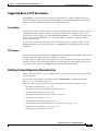
Supporting Reverse TCP Connections 2-9
Front-Ending 2-9
TCP Streams 2-9
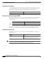
Defining Terminal Operation Characteristics 2-9
Specifying the Terminal Type 2-10
Setting the Terminal Screen Length and Width 2-10
Defining the Escape Character 2-10
Specifying the International Character Display 2-11
Setting Character Padding 2-12
Disabling Enhanced Editing Mode 2-12
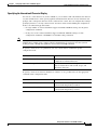
Providing Line Connection Information after the Login Prompt
Enabling Password Checking at Login 2-13
Checking Password Examples 2-13
2-12
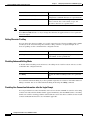
Configuring Terminal Banner Messages 2-14
Configuring a Message-of-the-Day Banner 2-14
Configuring a Line Activation Message 2-14
Configuring an Incoming Message Banner 2-14
Configuring an Idle Terminal Message 2-15
Enabling or Disabling the Display of Messages 2-15
Banner Message Example 2-15
CHAPTER
3
Initially Configuring the Cisco DSLAM
Methods for Configuring the DSLAM
Port and Slot Configuration
3-2
Configuration Prerequisites
3-4
3-1
3-1
Verifying Installed DSLAM Software and Hardware
Configuring the BOOTP Server
3-5
Setting the Subtend Node Identifier
Configuring the ATM Address
3-4
3-6
3-6
Configuring ATM Addressing 3-6
Using the ATM Default Addressing Scheme
Manually Setting the ATM Address 3-8
3-7
Modifying the Physical Layer Configuration of the Default ATM Interface
3-8
Configuration Guide for Cisco DSLAMs with NI-2
OL-2074-03
v
Contents
Configuring IP Interface Parameters 3-11
Defining an IP address 3-12
Defining Subnet Mask Bits 3-12
Testing the Ethernet Connection
3-14
Configuring Network Clocking 3-14
Configuring Network Clock Priorities and Sources
Configuring the Transmit Clocking Source 3-17
Providing Clock Synchronization Services 3-18
Configuring the Network Routing
3-16
3-19
Configuring NI-2 Card and APS Link Redundancy 3-19
NI-2 Card Redundancy Overview 3-19
NI-2 Cold Redundancy 3-19
Automatic Protection Switching 3-20
Restrictions 3-20
Supported Platforms 3-21
Prerequisites 3-21
Configuration Tasks 3-21
Configure the NI-2 Cards for File Synchronization
Verifying File Synchronization 3-22
Troubleshooting Tips 3-22
Monitoring Redundancy States 3-23
Configuration Examples 3-23
Configuring the Time, Date, and System Name
3-22
3-24
Configuring SNMP Management 3-24
Understanding SNMP 3-24
SNMP Notifications 3-26
MIBs and RFCs 3-28
SNMP Versions 3-29
SNMP Configuration Task List 3-30
Creating or Modifying an SNMP View Record 3-31
Creating or Modifying Access Control for an SNMP Community 3-31
Specifying an SNMP-Server Engine Name (ID) 3-32
Specifying SNMP-Server Group Names 3-32
Configuring SNMP-Server Hosts 3-32
Configuring SNMP-Server Users 3-32
Setting the Contact, Location, and Serial Number of the SNMP Agent 3-33
Defining the Maximum SNMP Agent Packet Size 3-33
Limiting the Number of TFTP Servers Used via SNMP 3-33
Monitoring and Troubleshooting SNMP Status 3-33
Configuration Guide for Cisco DSLAMs with NI-2
vi
OL-2074-03
Contents
Disabling the SNMP Agent 3-34
Configuring SNMP Notifications 3-34
Configuring the DSLAM to Send SNMP Notifications 3-34
Changing Notification Operation Values 3-35
Controlling Individual RFC 1157 SNMP Traps 3-36
Configuring the DSLAM as an SNMP Manager 3-36
Security Considerations 3-36
SNMP Sessions 3-36
Enabling the SNMP Manager 3-37
Monitoring the SNMP Manager 3-37
SNMP Configuration Examples 3-37
MIB Features in Cisco IOS Release 12.2DA 3-38
Standard MIB Modules 3-38
Cisco Enterprise MIB Modules 3-41
Storing the Configuration
3-44
Testing the Configuration 3-44
Confirming the Hardware Configuration 3-44
Confirming the Software Version 3-45
Confirming the Ethernet Configuration 3-45
Confirming the ATM Address 3-46
Testing the Ethernet Connection 3-46
Confirming the ATM Connections 3-47
Confirming the ATM Interface Configuration 3-47
Confirming the Interface Status 3-48
Confirming Virtual Channel Connections 3-48
Confirming the Running Configuration 3-48
Confirming the Saved Configuration 3-50
CHAPTER
4
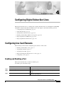
Configuring Digital Subscriber Lines
4-1
Configuring Line Card Elements 4-1
Enabling and Disabling a Port 4-1
Assigning Port Names 4-2
Assigning Circuit IDs 4-3
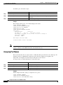
Displaying Debugging Information for a Port
Configuring a Slot 4-7
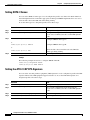
Using DSL Profiles 4-9
Creating, Modifying, or Deleting a Profile
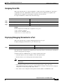
Copying a Profile 4-11
Attaching or Detaching a Profile 4-12
Displaying a Profile 4-13
4-3
4-10
Configuration Guide for Cisco DSLAMs with NI-2
OL-2074-03
vii
Contents
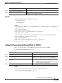
Setting DSL Profile Parameters 4-14
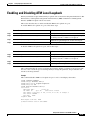
Enabling and Disabling Alarms 4-14
Enabling and Disabling LinkUp/Down Traps 4-16
Enabling and Disabling Payload Scrambling 4-17
Setting CAP Upstream and Downstream Baud Rate Margins 4-17
Setting Upstream and Downstream Bit Rates 4-19
Setting Bit Rate Parameters for ATU-C CAP Interfaces 4-19
Setting Bit Rate Parameters for DMT Interfaces 4-21
Setting DMT Minrate Blocking 4-22
Setting Bit Rate Parameters for STU-C Interfaces 4-23
Setting Bit Rate Parameters for SHTU-C Interfaces 4-24
Setting Signal-to-Noise Ratio Margins 4-24
ATU-C CAP and ATU-C Flexi CAP Interfaces 4-24
ATU-C 4DMT and 8xDMT Interfaces 4-25
SHTU-C Interfaces 4-26
Monitoring Signal-to-Noise Ratio 4-27
Setting DMT Power-Management-Additional-Margin 4-27
Setting the Interleaving Delay 4-28
DMT Interfaces 4-29
CAP Interfaces 4-31
Setting the Number of Symbols per Reed-Solomon Codeword 4-32
Setting FEC Check (Redundancy) Bytes 4-34
Enabling and Disabling Trellis Coding 4-36
Setting the Overhead Framing Mode 4-37
Modifying the Operating Mode 4-41
Modifying the DMT Training Mode 4-42
Modifying the G.SHDSL Training Mode 4-44
Setting the Power Spectral Density Mask for ATU-C CAP and ATU-C flexi CAP
Defaults 4-45
Setting the Power Spectral Density Mask for SHTU-C 4-45
Setting SHTU-C Annex 4-46
Setting the ATU-C CAP CPE-Signature 4-46
Enabling and Disabling ATM Local Loopback
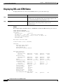
Displaying DSL and ATM Status
Displaying Hardware Information
4-44
4-47
4-48
4-49
Configuration Guide for Cisco DSLAMs with NI-2
viii
OL-2074-03
Contents
CHAPTER
5
Configuring In-Band Management
5-1
Configuring In-Band Management 5-1
Configuring In-Band Management in an SVC Environment 5-1
Configuring ATM ARP 5-2
Configuring In-Band Management in a PVC Environment 5-4
Mapping a Protocol Address to a PVC 5-5
Configuring a PVC-Based Map List 5-5
Configuring an SVC-Based Map List 5-6
CHAPTER
6
Configuring MPLS VPN Mapping
6-1
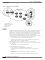
MPLS VPN Overview 6-1
Benefits 6-2
Comparison of Conventional VPNs and MPLS VPNs
Conventional VPNs 6-3
MPLS VPNs 6-3
6-3
Supported MPLS Features 6-3
Restrictions 6-4
Related Documents 6-5
New Terminology for MPLS
6-5
New Terminology for MPLS VPN mapping of routed sessions
Configuration Prerequisites
6-6
6-6
Configuration Tasks 6-6
Installing the Latest Cisco IOS Release 6-7
Enabling Cisco Express Forwarding 6-7
Configuring a VPN Forwarding Routing Instance 6-7
Creating a Loopback Interface and Associating It with a VRF 6-8
Creating a Loopback Interface to Be Associated with the Uplink Interface 6-8
Creating Uplink ATM Subinterfaces and Virtual Path Tunnels and Enabling MPLS
Configuring the PE-to-CE Interface Using RFC 1483 Routing 6-9
Configuring the PE-to-CE Interface Using RBE 6-10
Configuring the PE-to-CE Interface Using PPPoA 6-11
Configuring Routing Sessions 6-11
Configuring BGP Routing Sessions 6-12
Configuring MPLS Core Routing Protocols 6-12
Configuring RIP PE-to-CE Routing Sessions 6-13
Verifying VPN Operation 6-13
Configuration Samples 6-14
Site 1–PE1 Configuration—Cisco 6160 DSLAM
Site 2–PE2 Configuration—Cisco 6260 DSLAM
6-9
6-14
6-17
Configuration Guide for Cisco DSLAMs with NI-2
OL-2074-03
ix
Contents
CHAPTER
7
Configuring NI-2 IP Services
7-1
Configuring ATM Route-Bridged Encapsulation 7-1
Restrictions 7-2
Configuring ATM Route-Bridged encapsulation 7-2
ATM Route-Bridged encapsulation 7-2
ATM Route-Bridged encapsulation on an Unnumbered Interface 7-2
Concurrent Bridging and ATM Route-Bridged encapsulation 7-3
Configuring Layer 2 Tunnel Protocol 7-3
Configuring VPDN on the LAC 7-3
Monitoring and Troubleshooting VPDN and L2TP
7-4
Configuring the Cisco IOS DHCP Server 7-6
Prerequisites 7-8
DHCP Configuration Task List 7-8
Configuring a DHCP Database Agent or Disabling DHCP Conflict Logging
Excluding IP Addresses 7-9
Configuring a DHCP Address Pool 7-9
Configuring a DHCP Server Boot File 7-12
Configuring the Number of Ping Packets 7-12
Configuring the Timeout Value for Ping Packets 7-13
Enabling the Cisco IOS DHCP Server Feature 7-13
Monitoring and Maintaining the DHCP Server 7-13
Configuration Examples 7-14
DHCP Database Agent Configuration Example 7-14
DHCP Address Pool Configuration Example 7-14
Manual Bindings Configuration Example 7-15
Configuring DHCP Relay Support for Unnumbered Interfaces
Benefits 7-16
Configuration Task 7-16
7-9
7-16
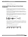
Configuring DHCP Option 82 Support for Route-Bridged Encapsulation
Prerequisites 7-18
Configuration Tasks 7-19
Configuring DHCP Option 82 for RBE 7-19
DHCP Option 82 for RBE Configuration Example 7-19
Configuring VPI/VCI Authentication 7-20
NAS-Port Attribute 7-20
Cisco Access Registrar Use of NAS-Port 7-21
Configuring VPI/VCI Authentication 7-21
7-17
Configuration Guide for Cisco DSLAMs with NI-2
x
OL-2074-03
Contents
Configuring PPP 7-21
Configuring PPPoA 7-22
Configuring a PPP Virtual Template 7-22
Configuring AAA Authentication 7-23
Configuring a RADIUS Server 7-24
Configuring PVCs 7-24
Configuring an IPCP Subnet Mask 7-25
Verifying and Troubleshooting PPPoA 7-26
Configuring PPPoE on ATM 7-27
PPPoE Stage Protocols 7-28
Benefits 7-28
Restrictions 7-29
Prerequisites 7-29
Configuration Tasks 7-29
CHAPTER
8
Configuring the Trunk and Subtended Interfaces
NI-2 Card and DSLAM Compatibility
NI-2 Subtending Support
8-1
8-1
8-2
Configuring 155 Mbps OC-3 SM and MM Interfaces 8-2
Default 155 Mbps ATM Interface Configuration Without Autoconfiguration
Manual 155 Mbps Interface Configuration 8-3
Configuring DS3 and E3 Interfaces 8-4
Default DS3 ATM Interface Configuration Without Autoconfiguration
Manual DS3 and E3 Interface Configuration 8-6
8-3
8-5
Configuring T1/E1 Multiplexing over ATM 8-7
How IMA Works 8-7
Supported Platforms 8-9
Prerequisites 8-9
Configuration Tasks 8-9
Configuring a Trunk Interface 8-9
Verifying the Trunk Interface 8-10
Configuring T1/E1 Interfaces 8-10
Verifying T1/E1 Interfaces 8-11
Configuring IMA Interfaces 8-11
Verifying the IMA Configuration 8-12
Troubleshooting Tips 8-12
Monitoring and Maintaining IMA 8-13
Configuration Guide for Cisco DSLAMs with NI-2
OL-2074-03
xi
Contents
Configuration Examples 8-14
IMA Trunk with IMA Subtended Chassis 8-14
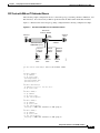
DS3 Trunk with IMA and T1 Subtended Chassis
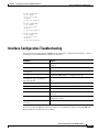
Interface Configuration Troubleshooting
CHAPTER
9
8-17
8-19
Loading System Software Images and Configuration Files
Configuring a Static IP Route
9-1
9-1
Retrieving System Software Images and Configuration Files 9-2
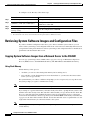
Copying System Software Images from a Network Server to the DSLAM
Using Flash Memory 9-2
Copying from a TFTP Server to Flash or Bootflash Memory 9-3
Copying from an rcp Server to Flash or Bootflash Memory 9-4
Verifying the Image in Flash Memory 9-6
Copying Configuration Files from a Network Server to the DSLAM 9-6
Copying from a TFTP Server to the DSLAM 9-6
Copying from an rcp Server to the DSLAM 9-7
Changing the Buffer Size for Loading Configuration Files 9-8
Displaying System Image and Configuration Information 9-9
9-2
Performing DSLAM Startup Tasks 9-9
Cisco Implementation of Environment Variables 9-9
BOOT Environment Variable 9-10
BOOTLDR Environment Variable 9-10
CONFIG_FILE Environment Variable 9-10
Control Environment Variables 9-10
Formatting Flash Memory 9-11
Recovering from Locked Blocks 9-11
Managing Flash Files 9-12
Setting the System Default Flash Device 9-12
Displaying the Current Default Flash Device 9-12
Showing a List of Files in Embedded Flash 9-13
Deleting Files in Embedded Flash 9-13
Performing General Startup Tasks 9-14
Entering Configuration Mode and Selecting a Configuration Source 9-14
Configuring the DSLAM from the Terminal 9-14
Configuring the DSLAM from Memory 9-15
Configuring the DSLAM from the Network 9-15
Copying a Configuration File Directly to the Startup Configuration 9-16
Configuration Guide for Cisco DSLAMs with NI-2
xii
OL-2074-03
Contents
Modifying the Configuration Register Boot Field 9-16
Using the Boot Field 9-16
Setting the Boot Field 9-17
Performing the Boot Field Modification Tasks 9-18
Specifying the Startup System Image 9-18
Booting from Flash Memory 9-19
Booting from Flash Memory Configuration Tasks 9-20
Loading from a Network Server 9-21
Using a Fault-Tolerant Booting Strategy 9-22
Specifying the Startup Configuration File 9-23
Downloading the Network Configuration File 9-24
Downloading the Host Configuration File 9-25
Setting the CONFIG_FILE Environment Variable 9-26
Clearing the Configuration Information 9-26
Booting the Enhanced OC-3/OC-3 NI-2 Card
9-27
Correcting Bootup Problems 9-27
Running Cisco IOS Release 12.1(7)DA2 to 12.2(10)DA on a New NI-2 Card
Using Rommon to Recover from Corrupted dboot2 Images 9-28
Redundant NI-2 Card Operation
9-28
9-29
Storing System Images and Configuration Files 9-30
Copying System Images from Flash Memory to a Network Server 9-30
Copying from Flash Memory to a TFTP Server 9-30
Copying from Flash Memory to an rcp Server 9-31
Copying Configuration Files from the DSLAM to a Network Server 9-33
Copying from the DSLAM to a TFTP Server 9-33
Copying from the DSLAM to an rcp Server 9-33
Configuring a DSLAM as a TFTP Server 9-35
Designating a DSLAM as a TFTP Server 9-35
Configuring Flash Memory as a TFTP Server 9-36
Performing Prerequisite Tasks 9-36
Configuring the Flash Server 9-37
Configuring the Client DSLAM 9-37
Verifying the Client DSLAM 9-38
Configuring the DSLAM for Other Types of Servers 9-39
Specifying Asynchronous Interface Extended BOOTP Requests
9-39
Configuration Guide for Cisco DSLAMs with NI-2
OL-2074-03
xiii
Contents
Configuring the Remote Shell and Remote Copy Functions 9-40
Cisco Implementation of rsh and rcp Protocols 9-40
Using the rsh Protocol 9-40
Maintaining rsh Security 9-40
Using the rcp Protocol 9-41
Configuring a DSLAM to Support Incoming rcp Requests and rsh Commands 9-41
Configuring the DSLAM to Accept rcp Requests from Remote Users 9-42
Configuring the DSLAM to Allow Remote Users to Execute Commands Using rsh
Turning Off DNS Lookups for rcp and rsh 9-43
Configuring the Remote Username for rcp Requests 9-44
Remotely Executing Commands Using rsh 9-44
Manually Loading a System Image from ROM Monitor
Manually Booting from Flash Memory 9-46
Manually Booting from a Network File 9-47
9-43
9-45
INDEX
Configuration Guide for Cisco DSLAMs with NI-2
xiv
OL-2074-03
F I G U R E S
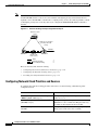
Figure 2-1
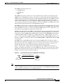
EXEC and Daemon Creation on a Line with No Modem Control
Figure 2-2
EXEC and Daemon Creation on a Line Configured for Incoming and Outgoing Calls
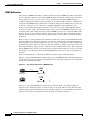
Figure 2-3
EXEC and Daemon Creation on a Line Configured for Continuous CTS
Figure 3-1
Two Methods of Configuring a DSLAM
Figure 3-2
ATM Address Format Defaults
Figure 3-3
Transmit Clock Distribution
Figure 3-4
Transmit Clocking Priority Configuration Example
Figure 3-5
Communication Between an SNMP Agent and Manager
Figure 3-6
Trap Successfully Sent to SNMP Manager
Figure 3-7
Inform Request Successfully Sent to SNMP Manager
Figure 3-8
Trap Unsuccessfully Sent to SNMP Manager
Figure 3-9
Inform Request Unsuccessfully Sent to SNMP Manager
Figure 5-1
PVC Map List Configuration Example
5-6
Figure 5-2
SVC Map List Configuration Example
5-7
Figure 6-1
VPNs with a Service Provider Backbone
Figure 6-2
Simple Hub and Spoke MPLS VPN Network Diagram
Figure 7-1
ATM Route-Bridged Encapsulation
Figure 7-2
DHCP Request for an IP Address from a DHCP Server
Figure 7-3
Network Topology Using ATM RBE and DHCP
Figure 7-4
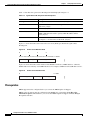
Format of the Agent Remote ID Suboption
Figure 7-5
Format of the NAS Port Field
7-18
Figure 7-6
Format of the Interface Field
7-18
Figure 7-7
PPPoE on ATM Sample Network Topology
Figure 8-1
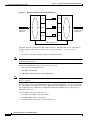
IMA Inverse Multiplexing and Demultiplexing
Figure 8-2
IMA Trunk with IMA Subtended Chassis
Figure 8-3
DS3 Trunk with IMA and T1 Subtended Chassis
2-5
2-6
2-7
3-2
3-7
3-15
3-16
3-25
3-26
3-27
3-27
3-28
6-2
6-14
7-1
7-7
7-17
7-17
7-27
8-8
8-14
8-17
Configuration Guide for Cisco DSLAMs with NI-2
OL-2074-03
xv
Figures
Configuration Guide for Cisco DSLAMs with NI-2
xvi
OL-2074-03
T A B L E S
Table 1
Font Conventions
Table 2
Command Syntax Conventions
Table 1-1
Command Modes
Table 3-1
NI-2 Card and Chassis Compatibility
Table 3-2
NI-2 Port Assignments
3-3
Table 3-3
Subnetting Parameters
3-12
Table 3-4
Redundant NI-2 Cards and Chassis Compatibility
Table 3-5
SNMP Security Models and Levels
Table 4-1
ATU-C CAP and ATU-C Flexi CAP Upstream Baud Rates and Corresponding Bit Rates
Table 4-2
ATU-C CAP and ATU-C Flexi CAP Downstream Baud Rates and Corresponding Bit Rates
Table 4-3
Allowable Ranges and Default Values for DMT Bit Rates
Table 4-4
Achievable Combinations of Interleaving Delay and Symbols per Reed Solomon Codeword for Different Bit Rate
Ranges 4-29
Table 4-5
Downstream Interleaving Delay
Table 4-6
Symbols-per-Codeword Values for Different Bit Rate Ranges
Table 4-7
Achievable Combinations of FEC Check Bytes and Symbols per Reed-Solomon Codeword for Different Bit Rate
Ranges 4-34
Table 6-1
MPLS Terminology
Table 7-1
show vpdn tunnel all Field Descriptions
Table 7-2
VPDN Monitoring and Maintaining Commands
Table 7-3
VPDN Troubleshooting Commands
Table 7-4
DHCP Address Pool Devices
Table 7-5
Agent Remote ID Suboption Field Descriptions
Table 7-6
Agent Remote ID Suboption Field Values
Table 7-7
PPPoE Stage Protocols
Table 8-1
NI-2 Card and DSLAM Chassis Compatibility
Table 8-2
Supported Platforms for T1/E1 Multiplexing over ATM
Table 8-3
Commands for Monitoring and Maintaining IMA
Table 9-1
Configuration Register Bootfield Description
xx
xxi
1-2
3-3
3-21
3-29
4-18
4-18
4-21
4-31
4-33
6-5
7-5
7-5
7-6
7-14
7-18
7-20
7-28
8-1
8-9
8-13
9-17
Configuration Guide for Cisco DSLAMs with NI-2
OL-2074-03
xvii
Tables
Configuration Guide for Cisco DSLAMs with NI-2
xviii
OL-2074-03
About This Guide
This preface tells you who should read this guide, the purpose of the guide, how the guide is organized,
and the document conventions used.
Audience
This guide is written for anyone who installs or operates Cisco digital subscriber line access
multiplexers (DSLAMs) with NI-2 controller cards. This includes the following chassis:
•
Cisco 6015 DSLAM
•
Cisco 6130 DSLAM
•
Cisco 6160 DSLAM
•
Cisco 6260 DSLAM
Purpose
The Configuration Guide for Cisco DSLAMs with NI-2 describes protocols, configuration tasks, and
Cisco IOS software functionality and contains comprehensive configuration examples. After completing
the Cisco IOS configuration procedures covered in this guide, refer to the appropriate related documents.
For additional information on related documentation, see “Related Documentation” later in this preface.
Organization
This guide is organized as follows:
•
Chapter 1, “Cisco DSLAM User Interface,” describes the DSLAM user interface and provides
instructions for using the command-line interface. This chapter describes how to access and list
the commands available in each command mode, and explains the primary uses for each
command mode.
•
Chapter 2, “Configuring Terminal Lines and Modem Support,” explains how to configure lines,
modems, and terminal settings to access the ATM switch for management purposes.
•
Chapter 3, “Initially Configuring the Cisco DSLAM,” describes the initial configuration of the
Cisco DSLAM.
Configuration Guide for Cisco DSLAMs with NI-2
OL-2074-03
xix
•
Chapter 4, “Configuring Digital Subscriber Lines,” describes how to configure the DSLAM for
digital subscriber line (DSL) service.
•
Chapter 5, “Configuring In-Band Management,” describes how to configure in-band management
for the DSLAM.
•
Chapter 6, “Configuring MPLS VPN Mapping,” describes how to configure Cisco Multiprotocol
Label Switching (MPLS) Virtual Private Network (VPN) mapping of RFC 1483 routed sessions.
•
Chapter 7, “Configuring NI-2 IP Services,” describes how to configure Cisco NI-2 IP services.
•
Chapter 8, “Configuring the Trunk and Subtended Interfaces,” describes configuring the trunk and
subtended interfaces on the Cisco DSLAM NI-2 card.
•
Chapter 9, “Loading System Software Images and Configuration Files,” describes how to load and
maintain system software images and configuration files.
•
Index
Other information necessary for ATM configuration tasks available on Cisco DSLAMs is contained in
the ATM Switch Router Software Configuration Guide. Here are chapter locations for subjects treated in
that guide:
•
Chapter 4, “Configuring System Management Functions”
•
Chapter 5, “Configuring ATM Network Interfaces”
•
Chapter 6, “Configuring Virtual Connections”
•
Chapter 7, “Configuring Operation, Administration, and Maintenance”
•
Chapter 8, “Configuring Resource Management”
•
Chapter 9, “Configuring ILMI”
•
Chapter 10, “Configuring ATM Routing and PNNI”
•
Chapter 11, “Using Access Control”
•
Chapter 14, “Configuring ATM Accounting and ATM RMON”
•
Chapter 16, “Configuring Signalling Features”
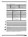
Conventions
This publication uses the document conventions described in this section.
Table 1
Font Conventions
Type Convention
Definition
Sample
Times bold
Used for any argument, command,
keyword, or punctuation that is part of a
command that you enter in text and
command environments.
This is similar to the UNIX
route command.
Also used for names of some GUI elements.
Times italic
Used for publication names and for
emphasis.
See the Cisco 6100 Series User
Guide for further details.
Configuration Guide for Cisco DSLAMs with NI-2
xx
OL-2074-03
Table 1
Font Conventions (continued)
Type Convention
Definition
Sample
Courier
Used for screen displays, prompts,
and scripts.
Are you ready to continue?
Courier bold
Used to indicate what you enter in examples Login: root
of command environments.
Password: <password>
Table 2
[Y]
Command Syntax Conventions
Convention
Definition
Sample
Vertical bar ( | )
Separates alternative, mutually
exclusive elements.
offset-list {in | out} offset
Square brackets ([ ])
Indicate optional elements.
[no] offset-list {in | out}
offset
Braces ({ })
Indicate a required choice.
offset-list {in | out} offset
Braces within square brackets Indicate a required choice within an
([{ }])
optional element.
[{letter\number}Enter]
Boldface
Indicates commands and keywords that [no] offset-list {in | out}
you enter literally as shown.
offset
Italic
Indicates arguments for which you
supply values.
Note
offset-list {in | out} offset
In contexts that do not allow
italics, arguments are enclosed
in angle brackets (< >).
Note
Means reader take note. Notes contain helpful suggestions or references to material not covered in the
manual.
Tip
Means the following information will help you solve a problem. The tips information might not be
troubleshooting or even an action, but could be useful information or information that might save time.
Caution
Warning
Means reader be careful. In this situation, you might do something that could result in equipment
damage or loss of data.
Means danger. You are in a situation that could cause bodily injury. Before you work on any
equipment, you must be aware of the hazards involved with electrical circuitry and be familiar with
standard practices for preventing accidents. To see translated versions of the warning, refer to the
Regulatory Compliance and Safety document that accompanied the device.
Configuration Guide for Cisco DSLAMs with NI-2
OL-2074-03
xxi
Related Documentation
A complete list of DSL hardware documentation is available on the World Wide Web at this URL:
http://www.cisco.com/univercd/cc/td/doc/product/dsl_prod/index.htm
A complete list of all DSL IOS software documentation is available at this URL:
http://www.cisco.com/univercd/cc/td/doc/product/dsl_prod/ios_dsl/index.htm
In the ATM software product related documentation, look for information on the Cisco LightStream 1010
switch, which uses the same software base as the NI-2 DSL systems. The documentation is available at:
http://www.cisco.com/univercd/cc/td/doc/product/atm/index.htm
Obtaining Documentation
These sections explain how to obtain documentation from Cisco Systems.
World Wide Web
You can access the most current Cisco documentation on the World Wide Web at this URL:
http://www.cisco.com
Translated documentation is available at the following URL:
http://www.cisco.com/public/countries_languages.shtml
Documentation CD-ROM
Cisco documentation and additional literature are available in a Cisco Documentation CD-ROM
package, which is shipped with your product. The Documentation CD-ROM is updated monthly and may
be more current than printed documentation. The CD-ROM package is available as a single unit or
through an annual subscription.
Ordering Documentation
You can order Cisco documentation in these ways:
•
Registered Cisco.com users (Cisco direct customers) can order Cisco product documentation from
the Networking Products MarketPlace:
http://www.cisco.com/cgi-bin/order/order_root.pl
•
Registered Cisco.com users can order the Documentation CD-ROM through the online Subscription
Store:
http://www.cisco.com/go/subscription
•
Nonregistered Cisco.com users can order documentation through a local account representative by
calling Cisco Systems Corporate Headquarters (California, U.S.A.) at 408 526-7208 or, elsewhere
in North America, by calling 800 553-NETS (6387).
Configuration Guide for Cisco DSLAMs with NI-2
xxii
OL-2074-03
Documentation Feedback
You can submit comments electronically on Cisco.com. In the Cisco Documentation home page, click
the Fax or Email option in the “Leave Feedback” section at the bottom of the page.
You can e-mail your comments to [email protected].
You can submit your comments by mail to the following address:
Cisco Systems
Attn: Document Resource Connection
170 West Tasman Drive
San Jose, CA 95134-9883
We appreciate your comments.
Obtaining Technical Assistance
Cisco provides Cisco.com as a starting point for all technical assistance. Customers and partners can
obtain documentation, troubleshooting tips, and sample configurations from online tools by using the
Cisco Technical Assistance Center (TAC) Web Site. Cisco.com registered users have complete access
to the technical support resources on the Cisco TAC Web Site.
Cisco.com
Cisco.com is the foundation of a suite of interactive, networked services that provides immediate, open
access to Cisco information, networking solutions, services, programs, and resources at any time, from
anywhere in the world.
Cisco.com is a highly integrated Internet application and a powerful, easy-to-use tool that provides a
broad range of features and services to help you with these tasks:
•
Streamline business processes and improve productivity
•
Resolve technical issues with online support
•
Download and test software packages
•
Order Cisco learning materials and merchandise
•
Register for online skill assessment, training, and certification programs
To obtain customized information and service, you can self-register on Cisco.com. To access Cisco.com,
go to this URL:
http://www.cisco.com
Configuration Guide for Cisco DSLAMs with NI-2
OL-2074-03
xxiii
Technical Assistance Center
The Cisco TAC is available to all customers who need technical assistance with a Cisco product,
technology, or solution. Two types of support are available through the Cisco TAC: the Cisco TAC
Web Site and the Cisco TAC Escalation Center.
Cisco TAC inquiries are categorized according to the urgency of the issue:
•
Priority level 4 (P4)—You need information or assistance concerning Cisco product capabilities,
product installation, or basic product configuration.
•
Priority level 3 (P3)—Your network performance is degraded. Network functionality is noticeably
impaired, but most business operations continue.
•
Priority level 2 (P2)—Your production network is severely degraded, affecting significant aspects
of business operations. No workaround is available.
•
Priority level 1 (P1)—Your production network is down, and a critical impact to business operations
will occur if service is not restored quickly. No workaround is available.
The Cisco TAC resource that you choose is based on the priority of the problem and the conditions of
service contracts, when applicable.
Cisco TAC Web Site
You can use the Cisco TAC Web Site to resolve P3 and P4 issues yourself, saving both cost and time.
The site provides around-the-clock access to online tools, knowledge bases, and software. To access the
Cisco TAC Web Site, go to this URL:
http://www.cisco.com/tac
All customers, partners, and resellers who have a valid Cisco services contract have complete access to
the technical support resources on the Cisco TAC Web Site. The Cisco TAC Web Site requires a
Cisco.com login ID and password. If you have a valid service contract but do not have a login ID or
password, go to this URL to register:
http://www.cisco.com/register/
If you are a Cisco.com registered user, and you cannot resolve your technical issues by using the Cisco
TAC Web Site, you can open a case online by using the TAC Case Open tool at this URL:
http://www.cisco.com/tac/caseopen
If you have Internet access, it is recommended that you open P3 and P4 cases through the Cisco TAC
Web Site.
Cisco TAC Escalation Center
The Cisco TAC Escalation Center addresses priority level 1 or priority level 2 issues. These
classifications are assigned when severe network degradation significantly impacts business operations.
When you contact the TAC Escalation Center with a P1 or P2 problem, a Cisco TAC engineer
automatically opens a case.
To obtain a directory of toll-free Cisco TAC telephone numbers for your country, go to this URL:
http://www.cisco.com/warp/public/687/Directory/DirTAC.shtml
Before you call, check with your network operations center to determine the level of Cisco support
services to which your company is entitled: for example, SMARTnet, SMARTnet Onsite, or Network
Supported Accounts (NSA). When you call the center, have your service agreement number and your
product serial number available.
Configuration Guide for Cisco DSLAMs with NI-2
xxiv
OL-2074-03
C H A P T E R
1
Cisco DSLAM User Interface
This chapter describes the Cisco DSLAM user interface, provides instructions for using the
command-line interface, and describes how to use the help system. The chapter also describes the
command editing and command history features that enable you to recall previous command entries and
edit previously entered commands.
This chapter includes the following sections:
•
Understanding the User Interface, page 1-1
•
Accessing Command Modes, page 1-2
•
Understanding Command Modes, page 1-5
•
Using Context-Sensitive Help, page 1-11
•
Checking Command Syntax, page 1-13
•
Using the Command History Features, page 1-13
•
Using the Editing Features, page 1-15
•
Ending a Session, page 1-19
Understanding the User Interface
The Cisco DSLAM user interface provides access to several different command modes, each with
related commands. For security, the user interface provides three levels of access to commands:
•
User mode—Called user EXEC mode.
•
Privileged mode—The privileged mode is called privileged EXEC mode and requires a password.
Note
Because all commands available in user EXEC mode are also available in privileged EXEC
mode, user EXEC mode is referred to as EXEC mode in this guide.
From the privileged EXEC mode, you can access global configuration mode and three specific
configuration modes:
– Terminal
– Memory
– Network configuration
•
(ROM) monitor mode—This mode accesses a basic system kernel to which the Cisco DSLAM might
default at startup if it does not find a valid system image, or if its configuration file is corrupted.
Configuration Guide for Cisco DSLAMs with NI-2
OL-2074-03
1-1
Chapter 1
Cisco DSLAM User Interface
Accessing Command Modes
You can enter commands in uppercase, lowercase, or both. Only passwords are case sensitive. You can
abbreviate commands and keywords to a unique number of characters. For example, you can abbreviate
the show command as sh. After you enter the command line at the system prompt, press Return to
execute the command.
Most configuration commands have a no form. In general, follow these guidelines:
•
Use the no form of a command to disable a feature or function.
•
Use the command without the no keyword to re-enable a disabled feature or to enable a feature
disabled by default.
The context-sensitive help system allows you to obtain a list of commands available for each command
mode or a list of available options for a specific command by entering a question mark (?).
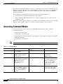
Accessing Command Modes
This section describes how to access the Cisco DSLAM command modes. Table 1-1 lists the
following information:
Note
Table 1-1
•
The command mode names.
•
The method to access that mode.
•
The prompt you see while in that mode. (For the purpose of this guide, the prompts use the default
node name DSLAM.)
•
The method to exit that mode.
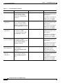
Table 1-1 does not include all of the possible ways to access or exit each command mode.
Command Modes
Command Mode
Access Method
Prompt
Exit Method
EXEC (user)
Log in to the switch or
Cisco DSLAM.
DSLAM>
Use the logout command.
Privileged EXEC
From user EXEC mode, use the
enable command and enter
your password.
DSLAM#
To return to user EXEC
mode, use the
disable command.
ROM monitor
From privileged EXEC mode,
use the reload command. Press
Break during the first
60 seconds while the
system boots.
rommon x>
The x represents the number
of commands that have been
entered at the DSLAM
prompt. To exit to ROM
monitor mode, use the
cont command.
Global configuration
From privileged EXEC mode,
use the configure command.
Use the keyword terminal to
enter commands from your
terminal.
DSLAM(config)#
To exit to privileged EXEC
mode, use the exit or end
command or press Ctrl-Z.
Configuration Guide for Cisco DSLAMs with NI-2
1-2
OL-2074-03
Chapter 1
Cisco DSLAM User Interface
Accessing Command Modes
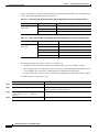
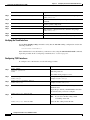
Table 1-1
Command Modes (continued)
Command Mode
Prompt
Exit Method
Interface configuration From global configuration
mode, enter by specifying
an interface with the
interface command.
DSLAM(config-if)#
To exit to global
configuration mode, use the
exit command.
Profile configuration
From global configuration
mode, enter by specifying a
profile with a dsl-profile
command.
DSLAM(cfg-dsl-profile)#
From global configuration
mode, enter by specifying a
management interface with a
line command.
DSLAM(config-line)#
From global configuration
mode, configure the ATM router
configuration with the atm
router pnni command.
DSLAM(config-atm-router)#
From ATM router configuration
mode, configure the PNNI
routing node with the
node command.
DSLAM(config-pnni-node)#
From global configuration
mode, configure redundancy
synchronization features with
the auto-sync command.
DSLAM(config-auto-sync)
From global configuration
mode, configure additional
redundancy options with the
redundancy command.
DSLAM(config-red)
Line configuration
ATM router
configuration
PNNI node
configuration
Auto-sync
configuration
Redundancy
configuration
Access Method
To exit directly to privileged
EXEC mode, use the end
command or press Ctrl-Z.
To exit to global
configuration mode, use the
exit command.
To exit directly to privileged
EXEC mode, use the end
command or press Ctrl-Z.
To exit to global
configuration mode, use the
exit command.
To exit directly to privileged
EXEC mode, use the end
command or press Ctrl-Z.
To exit to global
configuration mode, use the
exit command.
To exit directly to privileged
EXEC mode, use the end
command or press Ctrl-Z.
To exit to ATM router
configuration mode, use the
exit command.
To exit directly to privileged
EXEC mode, use the end
command or press Ctrl-Z.
To exit to global
configuration mode, use the
exit command.
To exit directly to privileged
EXEC mode, use the end
command or press Ctrl-Z.
To exit to global
configuration mode, use the
exit command.
To exit directly to privileged
EXEC mode, use the end
command or press Ctrl-Z.
Configuration Guide for Cisco DSLAMs with NI-2
OL-2074-03
1-3
Chapter 1
Cisco DSLAM User Interface
Accessing Command Modes
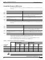
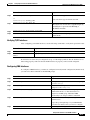
Table 1-1
Command Modes (continued)
Command Mode
Access Method
Prompt
Exit Method
VRF configuration
From global configuration
mode, configure a VPN
routing/forwarding (VRF)
routing table with the ip vrf
command.
DSLAM(config-vrf)
To exit to global
configuration mode, use the
exit command.
From global configuration
mode, configure the DHCP
address pool name and enter
DHCP pool configuration mode,
with the ip dhcp pool command.
DSLAM(dhcp-config)
From global configuration
mode, define an ATM
accounting file with the atm
accounting file command.
DSLAM(config-acct-file)#
DHCP pool
configuration
ATM accounting file
configuration
To exit directly to privileged
EXEC mode, use the end
command or press Ctrl-Z.
To exit to global
configuration mode, use the
exit command.
To exit directly to privileged
EXEC mode, use the end
command or press Ctrl-Z.
To exit to global
configuration mode, use the
exit command.
To exit directly to privileged
EXEC mode, use the end
command or press Ctrl-Z.
ATM accounting
From global configuration
selection configuration mode, define an ATM
accounting selection table entry
with the atm accounting
selection command.
DSLAM(config-acct-sel)#
ATM E.164 translation From global configuration
table configuration
mode, enter the
atm e164 translation-table
command.
DSLAM(config-atm-e164)
To exit to privileged
EXEC mode, use the
exit command, the end
command, or press Ctrl-Z.
ATM signaling
diagnostics
configuration
DSLAM(cfg-atmsig-diag)
To exit to global
configuration mode, use the
exit command.
From global configuration
mode, enter the command
atm signalling diagnostics
index.
To exit to global
configuration mode, use the
exit command.
To exit directly to privileged
EXEC mode, use the end
command or press Ctrl-Z.
To exit directly to privileged
EXEC mode, use the end
command or press Ctrl-Z.
Configuration Guide for Cisco DSLAMs with NI-2
1-4
OL-2074-03
Chapter 1
Cisco DSLAM User Interface
Understanding Command Modes
Understanding Command Modes
This section describes the various command modes and their levels of user access, including:
•
User EXEC Mode, page 1-5
•
Privileged EXEC Mode, page 1-5
•
ROM Monitor Mode, page 1-6
•
Global Configuration Mode, page 1-6
•
Interface Configuration Mode, page 1-7
•
Profile Configuration Mode, page 1-7
•
Line Configuration Mode, page 1-7
•
ATM Router Configuration Mode, page 1-8
•
PNNI Node Configuration Mode, page 1-8
•
Auto-sync Configuration Mode, page 1-8
•
Auto-sync Configuration Mode, page 1-8
•
VRF Configuration Mode, page 1-9
•
DHCP Pool Configuration Mode, page 1-9
•
ATM Accounting File Configuration Mode, page 1-10
•
ATM Accounting Selection Configuration Mode, page 1-10
•
ATM E.164 Translation Table Configuration Mode, page 1-10
•
ATM Signaling Diagnostics Configuration Mode, page 1-11
User EXEC Mode
When you log in to the Cisco DSLAM, you are in user EXEC, or simply EXEC, command mode. The
EXEC mode commands available at the user level are a subset of those available at the privileged level.
The user EXEC mode commands allow you to connect to remote switches, change terminal settings on
a temporary basis, perform basic tests, and list system information.
The user EXEC mode prompt consists of the DSLAM host name followed by the angle bracket (>):
Frodo>
or
DSLAM>
The default host name is DSLAM, unless it has been changed through use of the host name global
configuration command.
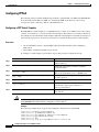
Privileged EXEC Mode
The privileged EXEC mode command set includes all user EXEC mode commands and the configure
command, through which you can access global configuration mode and the remaining configuration
submodes. Privileged EXEC mode also includes high-level testing commands, such as debug, and
commands that display potentially secure information.
Configuration Guide for Cisco DSLAMs with NI-2
OL-2074-03
1-5
Chapter 1
Cisco DSLAM User Interface
Understanding Command Modes
To enter or exit privileged EXEC mode, follow these steps:
Command
Task
Step 1
DSLAM> enable
Password:password
Enter privileged EXEC mode from EXEC mode.1
Step 2
DSLAM#
Enter privileged EXEC commands.
Step 3
DSLAM# disable
DSLAM>
Exit privileged EXEC mode and return to EXEC
mode.2
1.
The prompt changes to the DSLAM host name followed by the pound sign (#).
2.
The prompt changes back to the DSLAM host name followed by the angle bracket (>).
The system administrator uses the enable password global configuration command to set the password,
which is case sensitive. If an enable password was not set, you can access privileged EXEC mode only
from the console.
ROM Monitor Mode
ROM monitor mode provides access to a basic system kernel, from which you can boot the
Cisco DSLAM or perform diagnostic tests. The system can enter ROM mode automatically if the
Cisco DSLAM does not find a valid system image, or if the configuration file is corrupted. The ROM
monitor prompt is rommon x> without the DSLAM host name. The x represents the number of
commands entered into the prompt.
You can also enter ROM monitor mode by interrupting the boot sequence with the Break key during loading.
To return to EXEC mode from ROM monitor mode, use the cont command:
rommon 1> cont
DSLAM>
Global Configuration Mode
Global configuration mode provides access to commands that apply to the entire system. From global
configuration mode you can also enter the other configuration modes described in these sections.
Step 1
Command
Task
DSLAM# configure
Enter global configuration mode from privileged EXEC mode.
or
DSLAM# configure terminal
Step 2
Configuring from terminal, memory,
or network [terminal]? <CR>
This prompt appears only if you use the first option in Step 1. Specify
the source of the configuration commands at the prompt. You can
specify the terminal, NVRAM, or a file stored on a network server as
the source of configuration commands. The default is to enter
commands from the terminal console.
Step 3
DSLAM(config)#
Enter configuration commands.1
Step 4
DSLAM(config)# exit
Exit global configuration mode and return to privileged EXEC mode.
1.
The prompt changes to (config)#.
Configuration Guide for Cisco DSLAMs with NI-2
1-6
OL-2074-03
Chapter 1
Cisco DSLAM User Interface
Understanding Command Modes
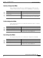
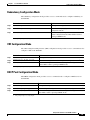
Interface Configuration Mode
Interface configuration mode provides access to commands that apply to an interface. Use these
commands to modify the operation of an interface such as an ATM, Ethernet, or asynchronous port.
Command
Task
Step 1
DSLAM# configure terminal
Go to global configuration mode.
Step 2
DSLAM(config)# interface interface-type
interface-number
Enter interface configuration mode from global configuration
mode.1
Step 3
DSLAM(config-if)# exit
Exit interface configuration mode and return to global
configuration mode. Enter end to return to privileged EXEC
mode.
1.
The prompt changes to (config-if)#.
Profile Configuration Mode
Profile configuration mode provides access to DSL profile commands. (See Chapter 4, “Configuring
Digital Subscriber Lines”.)
Command
Task
Step 1
DSLAM# configure terminal
Go to global configuration mode.
Step 2
DSLAM(config)# dsl-profile profile-name
Enter profile configuration mode and specify a profile.1
Step 3
DSLAM(cfg-dsl-profile)# exit
Exit profile mode and return to global configuration mode.
Enter end to return to privileged EXEC mode.
1.
The prompt changes to (cfg-dsl-profile)#.
Line Configuration Mode
Line configuration mode provides access to commands used to configure lines on the DSLAM.
Command
Task
Step 1
DSLAM# configure terminal
Go to global configuration mode.
Step 2
DSLAM(config)# line line-index
Enter line configuration mode from global configuration mode.1
Step 3
DSLAM(config-line)# exit
Exit profile mode and return to global configuration mode.
Enter end to return to privileged EXEC mode.
1.
The prompt changes to (config-line)#.
Configuration Guide for Cisco DSLAMs with NI-2
OL-2074-03
1-7
Chapter 1
Cisco DSLAM User Interface
Understanding Command Modes
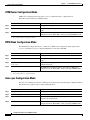
ATM Router Configuration Mode
ATM router configuration mode provides access to commands used to configure Private
Network-to-Network Interface (PNNI) routing.
Command
Task
Step 1
DSLAM# configure terminal
Go to global configuration mode.
Step 2
DSLAM(config)# atm router pnni
Enter ATM router configuration mode from global configuration
mode.1
Step 3
DSLAM(config-atm-router)# exit
Exit ATM router configuration mode and return to global
configuration mode. Enter end to return to privileged EXEC mode.
1.
The prompt changes to (config-atm-router)#.
PNNI Node Configuration Mode
The PNNI node configuration mode is a submode of ATM router configuration mode and provides
access to commands you use to configure PNNI nodes on the Cisco DSLAM.
Command
Task
Step 1
DSLAM# configure terminal
Go to global configuration mode.
Step 2
DSLAM(config)# atm router pnni
Enter ATM router configuration mode from global configuration
mode.1
Step 3
DSLAM(config-atm-router)# node
node-index
Enter PNNI node configuration mode from ATM router
configuration mode.2
Step 4
DSLAM(config-pnni-node)# exit
Exit PNNI node configuration mode and return to ATM router
configuration mode. Enter end to return to privileged EXEC mode.
1.
The prompt changes to (config-atm-router)#.
2.
The prompt changes to (config-pnni-node)#.
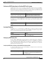
Auto-sync Configuration Mode
The auto-sync configuration mode is a submode for automatically synchronizing the configuration/flash
between the Cisco primary and secondary redundant NI-2s.
Command
Task
Step 1
DSLAM# configure terminal
Go to global configuration mode.
Step 2
DSLAM(config)# auto-sync
Enter auto-sync configuration mode.1
Step 3
DSLAM(config-auto-sync)# file
Enter the configuration or flash file that you want to be
automatically synchronized.
Step 4
DSLAM(config-auto-sync)# exit
Exit auto-sync configuration mode and return to global
configuration mode. Enter end to return to privileged EXEC mode.
1.
The prompt changes to (config-auto-sync)#.
Configuration Guide for Cisco DSLAMs with NI-2
1-8
OL-2074-03
Chapter 1
Cisco DSLAM User Interface
Understanding Command Modes
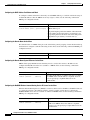
Redundancy Configuration Mode
The redundancy configuration mode provides access to commands used to configure redundancy on
the DSLAM.
Command
Task
Step 1
DSLAM# configure terminal
Go to global configuration mode.
Step 2
DSLAM(config)# redundancy
Enter redundancy configuration mode from global
configuration mode.1
Step 3
DSLAM(config-red)# exit
Exit redundancy configuration mode and return to
global configuration mode. Enter end to return to
privileged EXEC mode.
1.
The prompt changes to (config-red)#.
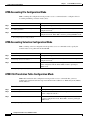
VRF Configuration Mode
The VPN routing/forwarding instance (VRF) configuration mode provides access to commands used to
configure a VRF on the DSLAM.
Command
Task
Step 1
DSLAM# configure terminal
Go to global configuration mode.
Step 2
DSLAM(config)# ip vrf vrf-name
Enter VRF configuration mode from global configuration mode.1
Step 3
DSLAM(config-vrf)# exit
Exit VRF configuration mode and return to global configuration mode.
Enter end to return to privileged EXEC mode.
1.
The prompt changes to (config-vrf)#.
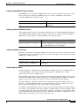
DHCP Pool Configuration Mode
The DHCP configuration mode provides access to commands used to configure a DHCP server on
the DSLAM.
Command
Task
Step 1
DSLAM# configure terminal
Go to global configuration mode.
Step 2
DSLAM(config)# ip dhcp pool name
Enter DHCP pool configuration mode from global configuration mode.1
Step 3
DSLAM(config-dhcp)# exit
Exit DHCP configuration mode and return to global configuration mode.
Enter end to return to privileged EXEC mode.
1.
The prompt changes to (config-dhcp)#.
Configuration Guide for Cisco DSLAMs with NI-2
OL-2074-03
1-9
Chapter 1
Cisco DSLAM User Interface
Understanding Command Modes
ATM Accounting File Configuration Mode
ATM accounting file configuration mode provides access to commands used to configure a file for
accounting and billing of virtual circuits (VCs).
Command
Task
Step 1
DSLAM# configure terminal
Go to global configuration mode.
Step 2
DSLAM(config)# atm accounting file
Enter ATM accounting file configuration mode from global
configuration mode.1
accounting-filename
Step 3
DSLAM(config-acct-file)# exit
1.
Exit ATM accounting file configuration mode and return to global
configuration mode. Enter end to return to privileged EXEC mode.
The prompt changes to (config-acct-file)#.
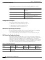
ATM Accounting Selection Configuration Mode
ATM accounting selection configuration mode provides access to commands used to specify the
connection data to be gathered from the DSLAM.
Command
Task
Step 1
DSLAM# configure terminal
Go to global configuration mode.
Step 2
DSLAM(config)# atm accounting selection
accounting-selection-index
Enter ATM accounting selection configuration mode from global
configuration mode.1
Step 3
DSLAM(config-acct-sel)# exit
Exit ATM accounting selection configuration mode and return to
global configuration mode. Enter end to return to privileged
EXEC mode.
1.
The prompt changes to (config-acct-sel)#.
ATM E.164 Translation Table Configuration Mode
ATM E.164 translation table configuration mode provides access to commands that you use to
configure the translation table that maps native E.164 format addresses to ATM end system (AESA)
format addresses.
Command
Task
Step 1
DSLAM# configure terminal
Go to global configuration mode.
Step 2
DSLAM(config)# atm e164 translation-table
Enter ATM E.164 translation table configuration mode from
global configuration mode.1
Step 3
DSLAM(config-atm-e164)# exit
Exit ATM E.164 translation table configuration mode and return
to global configuration mode. Enter end to return to privileged
EXEC mode.
1.
The prompt changes to (config-atm-e164)#.
Configuration Guide for Cisco DSLAMs with NI-2
1-10
OL-2074-03
Chapter 1
Cisco DSLAM User Interface
Using Context-Sensitive Help
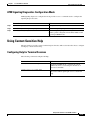
ATM Signaling Diagnostics Configuration Mode
ATM signaling diagnostics configuration mode provides access to commands used to configure the
signaling diagnostics table.
Command
Task
Step 1
DSLAM# configure terminal
Go to global configuration mode.
Step 2
DSLAM(config)# atm signalling diagnostics
Enter ATM signaling diagnostics configuration mode.
Step 3
DSLAM(cfg-atmsig-diag)# exit
Exit ATM signaling diagnostics configuration mode and
return to global configuration mode. Enter end to return
to privileged EXEC mode.
Using Context-Sensitive Help
The user interface provides context-sensitive help in all modes. This section describes how to configure
and display context-sensitive help.
Configuring Help for Terminal Sessions
The following commands configure full help.
Command
Task
DSLAM# terminal full-help
In privileged EXEC mode, configure the current
terminal session to receive help for the full set of
user-level commands.
DSLAM(config-line)# full-help
In line configuration mode, configure a specific line to
allow users without privileged access to obtain full
help.
Configuration Guide for Cisco DSLAMs with NI-2
OL-2074-03
1-11
Chapter 1
Cisco DSLAM User Interface
Using Context-Sensitive Help
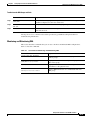
Displaying Context-Sensitive Help
To get help specific to a command mode, a command, a keyword, or an argument, perform one of
these tasks:
Using Word Help
Command
Task
help
Obtain a brief description of the help system in any
command mode.
abbreviated-command-entry?
Obtain a list of commands that begin with a particular
character string.
abbreviated-command-entry<Tab>
Complete a partial command name.
?
List all commands available for a particular command
mode.
command ?
List the associated keywords of a command.
command keyword ?
List the associated arguments of a keyword.
To view a list of commands that begin with a particular character sequence, type those characters
followed immediately by the question mark (?). Do not include a space. This form of help is called word
help, because it completes a word for you.
In this example, the system displays the possible commands in privileged EXEC mode that begin
with “co.”
DSLAM# co?
configure connect
copy
This form helps you determine the minimum subset that you can use to abbreviate a command.
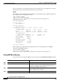
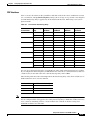
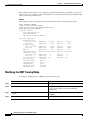
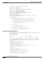
Command Syntax Help
To list keywords or arguments, enter a question mark (?) in place of a keyword or argument. Include a
space before the ?. This form of help is called command syntax help, because it reminds you which
keywords or arguments are applicable based on the command, keywords, and arguments you have
already entered.
This example demonstrates the use of command syntax help to complete the access-list command.
Entering the question mark (?) displays the allowed arguments:
DSLAM(config)# access-list ?
<1-99>
IP standard access list
<100-199> IP extended access list
Enter the access list number, 99, followed by a question mark (?) to display the allowed keywords:
DSLAM(config)# access-list 99 ?
deny
Specify packets to reject
permit Specify packets to forward
Configuration Guide for Cisco DSLAMs with NI-2
1-12
OL-2074-03
Chapter 1
Cisco DSLAM User Interface
Checking Command Syntax
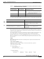
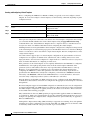
Enter the deny argument followed by a question mark (?) to display the next argument (host name or
IP address) and two keywords:
DSLAM(config)# access-list 99 deny ?
Hostname or A.B.C.D Address to match
any
Any source host
host
A single host address
Enter the IP address followed by a question mark (?) to display a final (optional) argument. The <cr>
indicates that you can press Return to execute the command:
DSLAM(config)# access-list 99 deny 131.108.134.0 ?
A.B.C.D Wildcard bits
<cr>
DSLAM(config)# <cr>
The system adds an entry to access list 99 that denies access to all hosts on subnet 131.108.134.0.
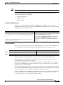
Checking Command Syntax
The user interface provides an error indicator (^) that appears in the command string in which you have
entered an incorrect or incomplete command, keyword, or argument.
This example shows a command entry that is correct up to the last element:
DSLAM# clock set 13:04:30 28 apr 98
^
% Invalid input detected at '^' marker.
The caret symbol (^) and help response indicate the location in which the error occurs. To list the correct
syntax, re-enter the command, substituting a question mark (?) where the error occurred:
DSLAM# clock set 13:32:00 23 February ?
<1993-2035> Year
DSLAM# clock set 13:32:00 23 February
Enter the year, using the correct syntax, and press Enter to execute the command:
DSLAM# clock set 13:32:00 23 February 1993
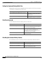
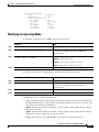
Using the Command History Features
The user interface provides a history or record of commands you enter. You can use the command history
feature for recalling long or complex commands or entries, including access lists. With the command
history feature, you can complete the tasks in the following sections:
•
Setting the Command History Buffer Size, page 1-14
•
Recalling Commands, page 1-14
•
Disabling the Command History Feature, page 1-14
Configuration Guide for Cisco DSLAMs with NI-2
OL-2074-03
1-13
Chapter 1
Cisco DSLAM User Interface
Using the Command History Features
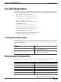
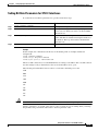
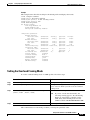
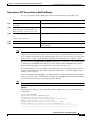
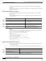
Setting the Command History Buffer Size
By default, the system records ten command lines in its history buffer. Use the following commands to
set the number of command lines the system records:
Command
DSLAM# terminal history
Task
[size
DSLAM(config-line)# history
number-of-lines]
[size
number-of-lines]
In privileged EXEC mode, enable the
command history feature for the current
terminal session.
In line configuration mode, enable the
command history feature for a specific line.
Recalling Commands
To recall commands from the history buffer, perform one of these tasks:
Key Sequence/Command
Press Ctrl-P or the Up Arrow key.
Task
1
Recall commands in the history buffer, beginning with
the most recent command. Repeat the key sequence to
recall successively older commands.
Press Ctrl-N or the Down Arrow key.1
Return to more recent commands in the history buffer
after recalling commands with Ctrl-P or the
Up Arrow key. Repeat the key sequence to recall
successively more recent commands.
DSLAM> show history
While in EXEC mode, list the last several commands
you have just entered.
1. The arrow keys function only on ANSI-compatible terminals such as VT100s.
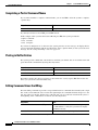
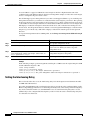
Disabling the Command History Feature
The command history feature is automatically enabled. Use the following commands to disable it:
Command
Task
DSLAM> terminal no history
In EXEC mode, disable the command history feature
for the current terminal session.
DSLAM(config-line)# no history
In line configuration mode, configure the line to
disable the command history feature.
Configuration Guide for Cisco DSLAMs with NI-2
1-14
OL-2074-03
Chapter 1
Cisco DSLAM User Interface
Using the Editing Features
Using the Editing Features
The user interface includes an enhanced editing mode that provides a set of editing functions similar to those
of the Emacs editor. Using the editing features, you can perform the tasks described in the following sections:
•
Enabling Enhanced Editing Mode, page 1-15
•
Moving Around on the Command Line, page 1-15
•
Completing a Partial Command Name, page 1-16
•
Pasting in Buffer Entries, page 1-16
•
Editing Command Lines that Wrap, page 1-16
•
Deleting Entries, page 1-17
•
Scrolling Down a Line or a Screen, page 1-17
•
Redisplaying the Current Command Line, page 1-18
•
Transposing Mistyped Characters, page 1-18
•
Controlling Capitalization, page 1-18
•
Designating a Keystroke as a Command Entry, page 1-18
•
Disabling Enhanced Editing Mode, page 1-19
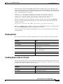
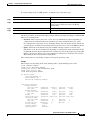
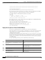
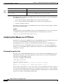
Enabling Enhanced Editing Mode
Although the current software release enables the enhanced editing mode by default, you can disable it
and revert to the editing mode of previous software releases. Use the following commands to re-enable
the enhanced editing mode:
Command
Task
DSLAM> terminal editing
In EXEC mode, enable the enhanced editing features
for the current terminal session.
DSLAM(config-line)# editing
In line configuration mode, enable the enhanced
editing features for a specific line.
Moving Around on the Command Line
Use these keystrokes to move the cursor around on the command line for corrections or changes:
Keystrokes
Press Ctrl-B or press the Left Arrow key.
Task
1
Press Ctrl-F or press the Right Arrow key.
Move the cursor back one character.
1
Move the cursor forward one character.
Press Ctrl-A.
Move the cursor to the beginning of the command line.
Press Ctrl-E.
Move the cursor to the end of the command line.
Press Esc B.
Move the cursor back one word.
Press Esc F.
Move the cursor forward one word.
1. The arrow keys function only on ANSI-compatible terminals such as VT100s.
Configuration Guide for Cisco DSLAMs with NI-2
OL-2074-03
1-15
Chapter 1
Cisco DSLAM User Interface
Using the Editing Features
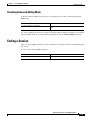
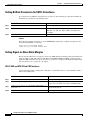
Completing a Partial Command Name
If you cannot remember a complete command name, you can use Tab to allow the system to complete
a partial entry:
Keystrokes
Task
Enter the first few letters and press Tab.
Complete a command name.
If your keyboard does not have Tab, press Ctrl-I instead.
In this example, when you enter the letters conf and press Tab, the system provides the
complete command:
DSLAM# conf<Tab>
DSLAM# configure
If you enter an ambiguous set of characters, the system generates an error message. To display the list
of legal commands beginning with the specified string, enter a question mark (?) after you see the error
message. See the “Using Word Help” section on page 1-12.
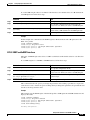
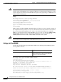
Pasting in Buffer Entries
The system provides a buffer that contains the last ten items you deleted. You can recall these items and
paste them in the command line by using these keystrokes:
Keystrokes
Task
Press Ctrl-Y.
Recall the most recent entry in the buffer.
Press Esc Y.
Recall the next buffer entry.
The buffer contains only the last ten items you have deleted or cut. If you press Esc Y more than 10
times, you cycle back to the first buffer entry.
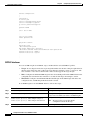
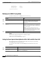
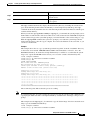
Editing Command Lines that Wrap
The new editing command set provides a wraparound feature for commands that extend beyond a single
line on the screen. When the cursor reaches the right margin, the command line shifts 10 spaces to the
left. You cannot see the first 10 characters of the line, but you can scroll back and check the syntax at
the beginning of the command. To scroll back, use these keystrokes:
Keystrokes
Task
1
Press Ctrl-B or the left arrow key repeatedly. Scroll back one character at a time to the beginning of
a command line to verify that you entered a lengthy
command correctly.
Press Ctrl-A.
Return directly to the beginning of the line.
1. The arrow keys function only on ANSI-compatible terminals such as VT100s.
Configuration Guide for Cisco DSLAMs with NI-2
1-16
OL-2074-03
Chapter 1
Cisco DSLAM User Interface
Using the Editing Features
In the following example, the access-list command entry extends beyond one line. When the cursor
reaches the end of the line, the line is shifted ten spaces to the left and redisplayed. The dollar sign ($)
indicates that the line has been scrolled to the left. Each time the cursor reaches the end of the line, the
line is again shifted ten spaces to the left.
DSLAM(config)#
DSLAM(config)#
DSLAM(config)#
DSLAM(config)#
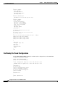
access-list 101 permit tcp 131.108.2.5 255.255.255.0 131.108.1
$ 101 permit tcp 131.108.2.5 255.255.255.0 131.108.1.20 255.25
$t tcp 131.108.2.5 255.255.255.0 131.108.1.20 255.255.255.0 eq
$108.2.5 255.255.255.0 131.108.1.20 255.255.255.0 eq 45
When you complete the entry, press Ctrl-A to check the complete syntax before pressing Return to
execute the command. The dollar sign ($) appears at the end of the line to indicate that the line has
scrolled to the right:
DSLAM(config)# access-list 101 permit tcp 131.108.2.5 255.255.255.0 131.108.1$
The Cisco DSLAM default is a terminal screen that is 80 columns wide. If you have a width other than
that, use the terminal width command to provide the correct width.
Use line wrapping together with the command history feature to recall and modify previous complex
command entries.
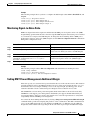
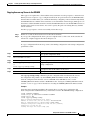
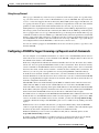
Deleting Entries
Use any of these keystrokes to delete command entries if you make a mistake or change your mind:
Keystrokes
Task
Press Delete or Backspace.
Erase the character to the left of the cursor.
Press Ctrl-D.
Delete the character at the cursor.
Press Ctrl-K.
Delete all characters from the cursor to the end of the
command line.
Press Ctrl-U or Ctrl-X.
Delete all characters from the cursor to the beginning
of the command line.
Press Ctrl-W.
Delete the word to the left of the cursor.
Press Esc D.
Delete from the cursor to the end of the word.
Scrolling Down a Line or a Screen
When you use the help facility to list the commands available in a particular mode, the list is often longer
than the terminal screen can display. In such cases, a More prompt appears at the bottom of the screen.
To respond to the More prompt, use these keystrokes:
Keystrokes
Task
Press Return.
Scroll down one line.
Press Space.
Scroll down one screen.
Press Esc.
Stop scrolling and return to the main prompt.
Configuration Guide for Cisco DSLAMs with NI-2
OL-2074-03
1-17
Chapter 1
Cisco DSLAM User Interface
Using the Editing Features
Redisplaying the Current Command Line
If you enter a command and a message appears on your screen, you can easily recall your current
command line entry. To do so, use these keystrokes:
Keystrokes
Task
Press Ctrl-L or Ctrl-R.
Redisplay the current command line.
Transposing Mistyped Characters
If you have mistyped a command entry, you can transpose the mistyped characters by using
these keystrokes:
Keystrokes
Task
Press Ctrl-T.
Transpose the character to the left of the cursor and the
character located at the cursor.
Controlling Capitalization
You can capitalize or lowercase words or capitalize a set of letters with these keystrokes:
Keystrokes
Task
Press Esc C.
Capitalize at the cursor.
Press Esc L.
Change the word at the cursor to lowercase.
Press Esc U.
Capitalize letters from the cursor to the end of the
word.
Designating a Keystroke as a Command Entry
To use a particular keystroke as an executable command, insert a system code:
Keystrokes
Task
Press Ctrl-V or Esc Q.
Insert a code to indicate to the system that the
keystroke that follows should be treated as a
command entry, not an editing key.
Configuration Guide for Cisco DSLAMs with NI-2
1-18
OL-2074-03
Chapter 1
Cisco DSLAM User Interface
Ending a Session
Disabling Enhanced Editing Mode
To disable enhanced editing mode and revert to the editing mode, use this command in privileged
EXEC mode:
Command
Task
DSLAM# terminal no editing
Disable the enhanced editing features for the local
line.
If you have prebuilt scripts that do not interact well when enhanced editing is enabled, you can disable
enhanced editing mode. To re-enable enhanced editing mode, use the terminal editing command.
Ending a Session
After you use the setup command or another configuration command, exit the Cisco DSLAM and quit
the session.
To end a session, use this EXEC command:
Command
Task
DSLAM> quit
End the session.
Configuration Guide for Cisco DSLAMs with NI-2
OL-2074-03
1-19
Chapter 1
Cisco DSLAM User Interface
Ending a Session
Configuration Guide for Cisco DSLAMs with NI-2
1-20
OL-2074-03
C H A P T E R
2
Configuring Terminal Lines and Modem Support
This chapter describes how to configure lines, modems, and terminal settings to access the ATM switch
for management purposes. The Cisco DSLAM has two types of terminal lines:
•
A console line
•
An auxiliary line
Most line setup is the same for all types of lines, but certain commands, such as those having to do with
modem control, apply only to the auxiliary port.
This chapter includes these sections:
•
Configuring Terminal Lines, page 2-1
•
Setting Up Modem Control on the Auxiliary Port, page 2-4
•
Configuring Terminal Banner Messages, page 2-14
Configuring Terminal Lines
Configuring terminal lines is a two-step process:
Step 1
Set up the lines for the terminals or other asynchronous devices attached to them.
Step 2
Configure the parameters for each line.
The tasks involved in these steps are described in the following sections:
•
Preparing to Configure Lines, page 2-2
•
Setting Communication Parameters, page 2-2
•
Configuring Flow Control for Communication, page 2-3
•
Specifying the Transport Protocol for a Specific Line, page 2-3
•
Establishing Terminal Session Limits, page 2-4
Configuration Guide for Cisco DSLAMs with NI-2
OL-2074-03
2-1
Chapter 2
Configuring Terminal Lines and Modem Support
Configuring Terminal Lines
Preparing to Configure Lines
Use line configuration mode to enter line configuration commands that affect a specified console,
auxiliary, or virtual terminal line. To enter line configuration mode, use this command in global
configuration mode:
Command
DSLAM(config)# line
[aux | console | vty]
Task
line-number
[ending-line-number]
Specify an auxiliary, console, or virtual
terminal line to configure.
The terminal from which you locally configure the system is attached to the console port.
Example
This example specifies the console port and begins line configuration mode:
DSLAM(config)# line con 0
DSLAM(config-line)#
The auxiliary port supports modem connections. See the “Setting Up Modem Control on the Auxiliary
Port” section on page 2-4, to set up modem support on the auxiliary port.
Configuring the console port or virtual terminal lines allows you to specify communication parameters
and automatic baud connections, and configure terminal operating parameters for the terminal you are
using. These tasks are described in the “Defining Terminal Operation Characteristics” section on
page 2-9.
You can also use the line command to create virtual terminal lines. This example shows how to create
and configure the maximum 4 virtual terminal lines with the no login command:
DSLAM(config)# line vty 0 4
DSLAM(config-line)# no login
Setting Communication Parameters
You can change the default parameters for terminal communications to meet the requirements of the
terminal or host to which you are attached. To do so, use one or more of these commands in line
configuration mode:
Command
Task
speed bps
txspeed bps
rxspeed bps
Set the line speed. Choose from line speed,
transmit speed, or receive speed. Speed
applies to the auxiliary port only.
databits {5 | 6 | 7 | 8}
Set the data bits.
stopbits {1 | 1.5 | 2}
Set the stop bits.
parity {none | even | odd | space | mark}
Set the parity bit.
This example shows how to configure the auxiliary line with a speed of 19,200 bps:
DSLAM(config)# line aux 0
DSLAM(config-line)# speed 19200
Configuration Guide for Cisco DSLAMs with NI-2
2-2
OL-2074-03
Chapter 2
Configuring Terminal Lines and Modem Support
Configuring Terminal Lines
Configuring Flow Control for Communication
On the auxiliary port, you can set both hardware and software flow control between the DSLAM and the
devices attached to it.
To configure flow control between the DSLAM and attached device, use one or more of the commands
in line configuration mode:
Command
Task
flowcontrol {none | software
[in | out] | hardware [in | out]}
Set the terminal flow control.
start ascii-number
Set the flow control start character.
stop-character ascii-number
Set the flow control stop character.
Allowable values for the start and stop-character commands are CHAR or 0 through 255.
Both software and hardware flow control are bidirectional. If you do not specify a direction, the DSLAM
enables software flow control in both directions. For information about setting up hardware flow control
on the EIA/TIA-232 line, see the hardware installation and maintenance manual for your product.
Specifying the Transport Protocol for a Specific Line
You can specify the protocols for individual lines by setting the protocol for incoming and outgoing
connections and changing the default (preferred) protocol for a line. The default transport protocol is
Telnet.
To specify transport protocols, use one or more of these commands in line configuration mode:
Command
Task
transport input {all | telnet | none}
Define which protocols can connect to a
specific line of the DSLAM.
transport output {all | telnet | none}
Determine the protocols for outgoing
connections from a line.
transport preferred {all | telnet | none}
Specify the protocol to use if the user did not
specify one.
transport preferred none
Prevent errant connection attempts.
The system accepts a host name entry at the EXEC system prompt as a Telnet command. If you
incorrectly type the host name, the system interprets the entry as an incorrect Telnet command and
displays an error message indicating that the host does not exist. The transport preferred none
command disables this option if you incorrectly type a command at the EXEC prompt, and the system
does not attempt to make a Telnet connection.
Configuration Guide for Cisco DSLAMs with NI-2
OL-2074-03
2-3
Chapter 2
Configuring Terminal Lines and Modem Support
Setting Up Modem Control on the Auxiliary Port
Establishing Terminal Session Limits
You can set a time limit on a terminal session. To limit terminal sessions, use the following command
in line configuration mode:
Command
session-timeout
Task
minutes [output]
Set the idle session timeout interval.
Setting Up Modem Control on the Auxiliary Port
This section describes modem control and how to configure it on the modem port:
•
Modem Control Process, page 2-5
•
Supporting Dial-In and Dial-Out Modems, page 2-5
•
Configuring a Line Timeout Interval, page 2-6
•
Closing Modem Connections, page 2-7
•
Configuring Rotary Groups, page 2-8
•
Configuring High-Speed Modem Support, page 2-8
•
Supporting Reverse TCP Connections, page 2-9
•
Defining Terminal Operation Characteristics, page 2-9
•
Specifying the Terminal Type, page 2-10
•
Setting the Terminal Screen Length and Width, page 2-10
•
Defining the Escape Character, page 2-10
•
Specifying the International Character Display, page 2-11
•
Setting Character Padding, page 2-12
•
Disabling Enhanced Editing Mode, page 2-12
•
Providing Line Connection Information after the Login Prompt, page 2-12
•
Enabling Password Checking at Login, page 2-13
•
Checking Password Examples, page 2-13
Configuration Guide for Cisco DSLAMs with NI-2
2-4
OL-2074-03
Chapter 2
Configuring Terminal Lines and Modem Support
Setting Up Modem Control on the Auxiliary Port
Modem Control Process
Figure 2-1 illustrates how modem control works on the DSLAM auxiliary port.
Figure 2-1
EXEC and Daemon Creation on a Line with No Modem Control
Ready
DTR high
Network
connection
closed
Exit
User-typed
activation
character
DTR high
Create
Ready and active daemon
DTR high
Create
EXEC
Ringing
Ready and active
S1201a
Incoming
network
connection
The figure shows two processes:
•
The create daemon process, used to create a TTY daemon that handles the incoming
network connection
•
The create EXEC process, used to create the process that interprets user commands
In the figure, the current signal state and the signal line are listed inside each box. The state of the line
is listed next to the box. (You can display the current state of a line with the show line command.) Events
that change that state appear in italics along the event path, with the software actions described within
the ovals.
Figure 2-1 illustrates line behavior when no modem control is set. The data terminal ready (DTR) output
is always high, and CTS and RING are ignored. The DSLAM creates an EXEC when the you type an
activation character. Incoming TCP connections occur instantly if the line is not in use and can be closed
only by the remote host.
Supporting Dial-In and Dial-Out Modems
To configure a line for both incoming and outgoing calls, use this command in line configuration mode:
Command
Task
DSLAM (config-line)# modem inout
Configure a line for both incoming and outgoing calls.
Configuration Guide for Cisco DSLAMs with NI-2
OL-2074-03
2-5
Chapter 2
Configuring Terminal Lines and Modem Support
Setting Up Modem Control on the Auxiliary Port
Figure 2-2 illustrates the modem in-out process.
Figure 2-2
EXEC and Daemon Creation on a Line Configured for Incoming and Outgoing Calls
Idle state
DTR high,
watching
ring
RING raised
Close
connection; DTR
low for 5 seconds
Create
EXEC
Incoming
network
connection
Create
daemon
DTR high,
Hang up
DTR going low
watching
ring
Ready
and
active
RING lowered
or exit
DTR high,
ignoring
ring
Ready
and
active
S1931
Network
connection
closed
If the line is activated by:
Note
•
Raising RING, it behaves exactly as a line configured with the modem dialin subcommand.
•
An incoming TCP connection, the line behaves similarly to a nonmodem line.
If your system uses dial-out modems, consider using access lists to prevent unauthorized use.
Configuring a Line Timeout Interval
You can change the interval that the DSLAM waits for CTS after raising DTR in response to RING from
the default of 15 seconds. To do so, use this command in line configuration mode:
Command
modem answer-timeout
Task
seconds
Configure modem line timing.
Configuration Guide for Cisco DSLAMs with NI-2
2-6
OL-2074-03
Chapter 2
Configuring Terminal Lines and Modem Support
Setting Up Modem Control on the Auxiliary Port
Closing Modem Connections
You can configure a line to close all connections from a user terminal when the terminal is turned off,
and prevent inbound connections to devices that are out of service. To do so, use this command in line
configuration mode:
Command
Task
modem printer
Configure a line to close all connections.
Figure 2-3 illustrates the modem printer process requirement for a high CTS throughout the use of
the line.
Figure 2-3
EXEC and Daemon Creation on a Line Configured for Continuous CTS
Idle state
DTR high,
watching
CTS
CTS raised
Close connection,
DTR low for
5 seconds
CTS lowered
DTR going
low
User-typed
activation
character
Ready
and
active
Create
EXEC
DTR high,
watching
CTS
CTS lowered
or exit
DTR high,
watching
CTS
Ready
Incoming network
connection
Create
daemon
DTR high,
watching
CTS
Ready
and
active
CTS lowered or
network
connection
closed
S1004a
Hang up
If CTS is not high, your typed input is ignored and incoming connections are refused (or stepped to the
next line in a rotary group).
A DSLAM can reliably detect a CTS signal change if the signal remains in the new state for at least one
full second.
Configuration Guide for Cisco DSLAMs with NI-2
OL-2074-03
2-7
Chapter 2
Configuring Terminal Lines and Modem Support
Setting Up Modem Control on the Auxiliary Port
Configuring Rotary Groups
You can make connections to the next free line in a group of lines, also called a rotary or hunt group. A
line can be in only one rotary group. A rotary group can consist of a single line or several contiguous
lines. The console line (line 0) cannot be in a rotary group.
If you want to assign the rotary as the single auxiliary port line you can do so because the auxiliary port
is not necessarily the same line number on all hardware. When you assign the line to a rotary group, you
do not have to track the actual line number. Another reason to use a rotary group is that if the device
supports local area transport (LAT), an inbound service can only be bound to a rotary group. It cannot
be bound to a port number.
To configure a rotary group, use this command in line configuration mode:
Command
rotary
Task
group
Add a line to the specified rotary group.
Configuring High-Speed Modem Support
Modems that operate over normal dial-up telephone lines at speeds of 9600 bps and higher do not
guarantee a specific throughput; instead, they operate at a speed that depends on the quality of the line,
the effectiveness of data compression algorithms on the data being transmitted, and other variables.
These modems use hardware flow control to stop the data from reaching the host by toggling an
EIA/TIA-232 signal when they cannot accept any more data.
In addition to hardware flow control, dial-up modems require special software handling. You must
configure the modems to:
•
Create an EXEC when you dial in.
•
Hang up when you exit the EXEC.
•
Close any existing network connections if the telephone line hangs up in the middle of a session.
The DSLAM supports hardware flow control on its CTS input, which is also used by the normal modem
handshake. To configure and use a high-speed modem, perform these tasks, beginning in line
configuration mode:
Command
Task
Step 1
DSLAM(config-line)# flowcontrol
hardware
In line configuration mode, enable outgoing hardware flow control
based on the CTS input.
Step 2
DSLAM(config-line)# end
Enter privileged EXEC command mode.
Step 3
DSLAM# debug modem
Display informational messages on the console terminal about
modem control events, such as signal transitions and automatic baud
progress.
Step 4
DSLAM# show line
Display the status of a line. In the detailed command output, a Status
line of Idle identifies inactive modem dial-in lines and all other
modem lines; a Status line of Ready identifies lines in use.
Configuration Guide for Cisco DSLAMs with NI-2
2-8
OL-2074-03
Chapter 2
Configuring Terminal Lines and Modem Support
Setting Up Modem Control on the Auxiliary Port
Supporting Reverse TCP Connections
The DSLAM can receive incoming connections on the auxiliary port. This capability allows you to
attach serial printers, modems, and other shared peripherals to the DSLAM and drive them remotely
from other systems. The DSLAM supports reverse TCP connections.
Front-Ending
The specific TCP port or socket to which you attach the peripheral device determines the type of service
the DSLAM provides on that line. When you attach the serial lines of a computer system or a data
terminal switch to the auxiliary port of the DSLAM, the DSLAM acts as a network front end for a host
that does not support the TCP/IP protocols. This arrangement is sometimes called front-ending or
reverse connection mode.
To connect the auxiliary port, the remote host or terminal must specify a particular TCP port on the
DSLAM. If Telnet protocols are required, that port is 2000 (decimal) plus the decimal value of the
line number.
TCP Streams
If a raw TCP stream is required, the port is 4000 (decimal) plus the decimal line number. The raw TCP
stream is usually the required mode for sending data to a printer.
The Telnet protocol requires that carriage return characters be translated into carriage return and line
feed character pairs. You can turn this translation off by specifying the Telnet binary mode option. To
specify this option, connect to port 6000 (decimal) plus the decimal line number.
Defining Terminal Operation Characteristics
In line configuration mode, you can set terminal operation characteristics for that line until you change
the line parameters.
You can temporarily change the line settings using the terminal EXEC commands described in
Chapter 1, “Cisco DSLAM User Interface.”
Define the terminal operation characteristics by performing the tasks in the following sections:
•
Specifying the Terminal Type, page 2-10
•
Setting the Terminal Screen Length and Width, page 2-10
•
Defining the Escape Character, page 2-10
•
Specifying the International Character Display, page 2-11
•
Setting Character Padding, page 2-12
•
Disabling Enhanced Editing Mode, page 2-12
•
Providing Line Connection Information after the Login Prompt, page 2-12
•
Enabling Password Checking at Login, page 2-13
•
Checking Password Examples, page 2-13
Configuration Guide for Cisco DSLAMs with NI-2
OL-2074-03
2-9
Chapter 2
Configuring Terminal Lines and Modem Support
Setting Up Modem Control on the Auxiliary Port
Specifying the Terminal Type
You can specify the type of terminal connected to a line. This feature has two benefits: it records the
type of terminal attached to a line, and it can inform the remote host of the terminal type for display
management. To specify the terminal type, use this command in line configuration mode:
Command
Task
terminal-type terminal-name
Specify the terminal type.
Setting the Terminal Screen Length and Width
By default, the DSLAM provides a screen display of 24 lines by 80 characters. You can reconfigure these
values if they do not meet the needs of your terminal by performing the following tasks in line
configuration mode:
Command
Task
Step 1
length screen-length
Set the screen length.
Step 2
width characters
Set the screen width.
The values set can be learned by some host systems that use this type of information in terminal
negotiation. Set a value of 0 for the screen length to disable pausing between windows of output.
Defining the Escape Character
You can define or modify the system escape function with the escape-character command in line
configuration mode:
Note
Command
Task
escape-character ascii-number
Change the system escape sequence. The escape
sequence indicates that the codes that follow have
special meaning. The default sequence is Ctrl-^.
If you are using the autoselect command, do not change the activation character from the default value
of Return. If you change this default, autoselect may not function immediately.
Configuration Guide for Cisco DSLAMs with NI-2
2-10
OL-2074-03
Chapter 2
Configuring Terminal Lines and Modem Support
Setting Up Modem Control on the Auxiliary Port
Specifying the International Character Display
You can use a 7-bit character set (such as ASCII) or you can enable a full 8-bit international character
set (such as ISO 8859) to allow special graphical and international characters for use in banners and
prompts, and to add special characters such as software flow control. You can configure these settings
globally by interface or locally at the user level. Use these criteria for determining the configuration
mode to use when setting up this feature:
Note
•
If a large number of connected terminals support nondefault ASCII bit settings, use the global
configuration commands.
•
If only a few of the connected terminals support nondefault ASCII bit settings, use line
configuration commands or the EXEC local terminal setting commands.
Setting the EXEC character width to 8 bits can cause failures. If you enter the help command on a
terminal that is sending parity, an unrecognized command message appears because the system is
reading all 8 bits, although the eighth bit is not needed for the help command.
To specify a character set on a global basis, use one or both of these commands in global
configuration mode:
Command
Task
default-value exec-character-bits {7 | 8}
Specify the character set used in EXEC and
configuration command characters.
default-value special-character-bits {7 | 8}
Specify the character set used in special characters
such as software flow control, hold, escape, and
disconnect characters.
To specify a character set based on hardware or software, or on a per-line basis, use the appropriate
command in line configuration mode:
Command
Task
databits {5 | 6 | 7 | 8}
Set the number of databits per character that are
generated and interpreted by hardware.
data-character-bits {7 | 8}
Set the number of databits per character that are
generated and interpreted by software.
Configuration Guide for Cisco DSLAMs with NI-2
OL-2074-03
2-11
Chapter 2
Configuring Terminal Lines and Modem Support
Setting Up Modem Control on the Auxiliary Port
Note
Command
Task
exec-character-bits {7 | 8}
Specify the character set used in EXEC and
configuration command characters on a per-line basis.
special-character-bits {7 | 8}
Specify the character set used in special characters
such as software flow control, hold, escape, and
disconnect characters on a per-line basis.
If you are using the autoselect function, set the activation character default to Return, and
exec-character-bits default to 7. If you change these defaults, the application does not recognize the
activation request.
Setting Character Padding
You can change the character padding on a specific output character. Character padding adds a number
of null bytes to the end of the string and can make a string conform to an expected length. To set
character padding, use this command in line configuration mode:
Command
Task
padding ascii-number count
Set padding count, on a specific output character,
ascii-number, for the specified line.
Disabling Enhanced Editing Mode
To disable enhanced editing mode and revert to the editing mode of earlier software releases, use this
command in line configuration mode:
Command
Task
no editing
Disable the enhanced editing features for a particular
line.
You can disable enhanced editing if you have prebuilt scripts that do not interact well when enhanced
editing is enabled. You can re-enable enhanced editing mode using the editing command.
Providing Line Connection Information after the Login Prompt
You can provide the host name, line number, and location each time an EXEC is started or an incoming
connection is made. The line number banner appears immediately after the EXEC banner or incoming
banner. It is useful for tracking problems with modems because it lists the host and line for the modem
connection. Modem information is also included if applicable.
Configuration Guide for Cisco DSLAMs with NI-2
2-12
OL-2074-03
Chapter 2
Configuring Terminal Lines and Modem Support
Setting Up Modem Control on the Auxiliary Port
To provide service line number information, use this command in global configuration mode:
Command
Task
service linenumber
Provide service line number information after the
EXEC or incoming banner.
Enabling Password Checking at Login
You can enable password checking on a particular line so that the user is prompted to enter a password
at the system login screen. You must then also specify a password. To do so, perform these tasks in line
configuration mode:
Command
Task
Step 1
login
Enable password checking on a per-line basis using the password
specified with the password command.
Step 2
password password
Assign a password to a particular line.
You can enable password checking on a per-user basis so that authentication is based on the user name
specified with the username global configuration command. To enable this type of password checking,
use one of these commands in line configuration mode:
Command
Task
login local
Enable password checking on a per-user
basis using the user name and password specified
with the username global configuration
command.
login tacacs
Select the TACACS-style user ID and
password-checking mechanism.
Use the login tacacs command with Terminal Access Controller Access Control System (TACACS) and
extended TACACS Plus.
By default, virtual terminals require passwords. If you do not set a password for a virtual terminal, it
responds to attempted connections by displaying an error message and closing the connection. Use the
no login command to disable this behavior and allow connections without a password.
Checking Password Examples
This example shows password checking enabled for a virtual terminal line 1:
DSLAM(config)# line vty 1
DSLAM(config-line)# login
DSLAM(config-line)# password letmein
This example shows password checking enabled on a per-user basis:
DSLAM(config)# username jksmith password 0 letmein
DSLAM(config)# username lmjones password 0 littlerock
DSLAM(config)# line vty 1
DSLAM(config-line)# login local
Configuration Guide for Cisco DSLAMs with NI-2
OL-2074-03
2-13
Chapter 2
Configuring Terminal Lines and Modem Support
Configuring Terminal Banner Messages
Configuring Terminal Banner Messages
The following sections explain how to configure terminal messages:
•
Configuring a Message-of-the-Day Banner, page 2-14
•
Configuring a Line Activation Message, page 2-14
•
Configuring an Incoming Message Banner, page 2-14
•
Configuring an Idle Terminal Message, page 2-15
•
Enabling or Disabling the Display of Messages, page 2-15
•
Banner Message Example, page 2-15
Configuring a Message-of-the-Day Banner
You can configure a message-of-the-day (MOTD) banner to display on all connected terminals. This
message is displayed at login and is useful for sending messages that affect all network users, such as
impending system shutdowns. To do so, use this command in global configuration mode:
Command
Task
banner motd c message c
Configure a message-of-the-day banner.
Configuring a Line Activation Message
You can configure a line activation message to display when an EXEC process such as line activation
or an incoming connection to a virtual terminal is created. To do so, use this command in global
configuration mode:
Command
Task
banner exec c message c
Configure a message to be displayed on terminals with
an interactive EXEC.
Configuring an Incoming Message Banner
You can configure a message to display on terminals connected to reverse Telnet lines. This message is
useful for providing instructions to users of these types of connections. Reverse Telnet connections are
described in more detail in the “Supporting Reverse TCP Connections” section on page 2-9.
To configure the message that will be sent on incoming connections, use this command in global
configuration mode:
Command
Task
banner incoming c message c
Configure messages to display on terminals connected
to reverse Telnet lines.
Configuration Guide for Cisco DSLAMs with NI-2
2-14
OL-2074-03
Chapter 2
Configuring Terminal Lines and Modem Support
Configuring Terminal Banner Messages
Configuring an Idle Terminal Message
You can configure messages to display on a console or terminal that is not in use. Also called a vacant
message, this message is different from the banner message displayed when an EXEC process is
activated. To configure an idle terminal message, use this command in line configuration mode:
Command
Task
vacant-message c message c
Display an idle terminal message.
Enabling or Disabling the Display of Messages
You can control display of the MOTD and line activation banners. By default, these banners display on
all lines. To suppress or resume these messages, use one of these commands in line configuration mode:
Command
Task
no exec-banner
Suppress banner display.
exec-banner
Resume the display of the EXEC or MOTD banners.
Banner Message Example
This example shows how to use the banner global configuration command and no exec-banner line
configuration command to notify your users that the server will be reloaded with new software:
DSLAM(config)# banner exec /
Enter TEXT message. End with the character '/'.
Unauthorized access prohibited./
DSLAM(config)# banner incoming /
You are connected to a Hayes-compatible modem.
Enter the appropriate AT commands.
Remember to reset anything to change before disconnecting.
/
DSLAM(config)# banner motd /
The switch will go down at 6pm for a software upgrade.
/
DSLAM(config)# line vty 0 4
DSLAM(config-line)# no exec-banner
DSLAM(config-line)#
Configuration Guide for Cisco DSLAMs with NI-2
OL-2074-03
2-15
Chapter 2
Configuring Terminal Lines and Modem Support
Configuring Terminal Banner Messages
Configuration Guide for Cisco DSLAMs with NI-2
2-16
OL-2074-03
C H A P T E R
3
Initially Configuring the Cisco DSLAM
This chapter describes how to initially configure the Cisco DSLAMs, and includes these sections:
•
Methods for Configuring the DSLAM, page 3-1
•
Port and Slot Configuration, page 3-2
•
Configuration Prerequisites, page 3-4
•
Verifying Installed DSLAM Software and Hardware, page 3-4
•
Configuring the BOOTP Server, page 3-5
•
Setting the Subtend Node Identifier, page 3-6
•
Configuring ATM Addressing, page 3-6
•
Modifying the Physical Layer Configuration of the Default ATM Interface, page 3-8
•
Configuring IP Interface Parameters, page 3-11
•
Testing the Ethernet Connection, page 3-14
•
Configuring Network Clocking, page 3-14
•
Configuring the Network Routing, page 3-19
•
Configuring NI-2 Card and APS Link Redundancy, page 3-19
•
Configuring the Time, Date, and System Name, page 3-24
•
Configuring SNMP Management, page 3-24
•
Storing the Configuration, page 3-44
•
Testing the Configuration, page 3-44
Methods for Configuring the DSLAM
The Cisco DSLAM default configuration is suitable for operation with most networks. By using network
management applications and the text-based command-line interface (CLI), you can configure and
customize all aspects of DSLAM operation to suit your needs.
The Cisco DSLAM ships with the ATM address autoconfigured, allowing the DSLAM to accomplish
the following tasks:
•
Automatically configure attached end systems using the Interim Local Management
Interface (ILMI) protocol.
•
Establish itself as a node in a single-level Private Network to Network Interface (PNNI)
routing domain.
Configuration Guide for Cisco DSLAMs with NI-2
OL-2074-03
3-1
Chapter 3
Initially Configuring the Cisco DSLAM
Port and Slot Configuration
The ILMI and PNNI protocols allow the DSLAM to be entirely self-configured when you use these
protocols with an IP address autoconfiguration mechanism such as BOOTP.
You must assign an IP address to allow up to eight simultaneous Telnet sessions to connect to the
DSLAM or to use the Simple Network Management Protocol (SNMP) system for the DSLAM. The
Ethernet IP address is assigned either manually or by a BOOTP server. See the “Configuring IP Interface
Parameters” section on page 3-11.
You can use either of two methods for configuring a DSLAM (see Figure 3-1):
•
From a local console or workstation—Connect to the console port or connect to the Ethernet port of
a DSLAM. This connection allows you to issue CLI commands directly to the DSLAM chassis.
•
From a remote console or workstation—Initiate a Telnet connection to a target DSLAM. Telnet
allows you to remotely issue CLI commands to that chassis.
Figure 3-1
Two Methods of Configuring a DSLAM
Switch
DSLAM
Workstation
Ethernet
port
Remote
console
Telnet
Console
port
Remote
workstation
Telnet
27308
Console
Local console or workstation connection
Remote console or workstation Telnet connection
Port and Slot Configuration
The DSLAM contains an NI-2 card and up to 32 line (modem) cards depending on the DSLAM. The slot
configurations on the different DSLAMs are as follows:
•
Cisco 6015 DSLAM
– Six line card slots
– One NI-2 card slot
•
Cisco 6100 DSLAM
– 32 line card slots
– Two NI-2 card slots (only one slot active)
Configuration Guide for Cisco DSLAMs with NI-2
3-2
OL-2074-03
Chapter 3
Initially Configuring the Cisco DSLAM
Port and Slot Configuration
•
Cisco 6130 DSLAM
– 32 line card slots
– Two NI-2 card slots (to provide redundancy)
•
Cisco 6160 DSLAM
– 32 line card slots
– Two NI-2 card slots (to provide redundancy)
•
Cisco 6260 DSLAM
– 30 line card slots
– Two NI-2 card slots (to provide redundancy)
Table 3-1 lists the NI-2 cards that can be installed in each of the DSLAM chassis, as well as the
associated product numbers.
Table 3-1
NI-2 Card and Chassis Compatibility
NI-2 Card
Product Number
Cisco 6015
Cisco 6100/6130
Cisco 6160
Cisco 6260
DS3+T1/E1 IMA1
NI-2-DS3-T1E1=
Yes
No
Yes2
Yes3
DS3/2DS3
NI-2-DS3-DS3=
No
Yes
Yes
Yes4 5
OC-3c/OC-3c SMF6
NI-2-155SM-155SM=
Yes
Yes
Yes
Yes7
OC-3c/OC-3c MMF8
NI-2-155MM-155MM=
Yes
Yes
Yes
Yes7
OC-3c/2DS3 SMF
NI-2-155SM-DS3=
No
No
Yes
No
OC-3c/2DS3 MMF
NI-2-155MM-DS3=
No
No
Yes
No
1. IMA = inverse multiplexing over ATM.
2. In a Cisco 6160 system, use only with the DS3/2DS3+8xT1 IMA I/O card (part number 6160-1-I/O-2=).
3. In a Cisco 6260 system, use only with the E1 I/O module.
4. When the DS3/2DS3 NI-2 card and the E3 I/O module are installed in the Cisco 6260 chassis, the system assumes E3 functionality.
5. In a Cisco 6260 system, use only with the E3 I/O module.
6. SMF = single-mode fiber.
7. In a Cisco 6260 system, use only with the OC-3c I/O module.
8. MMF = multimode fiber.
Line cards are assigned ports 1 to 4 or 1 to 8 in consecutive slots. Table 3-2 lists NI-2 port assignments.
See the Hardware Installation Guide for your specific DSLAM system for more detailed information
about possible subtending topologies.
Table 3-2
NI-2 Port Assignments
Port Type
OC3xOC3
OC3x2DS3
DS3x2DS3
DS3xE1/T1
Function
Switch,
Ethernet
eth 0/0
eth 0/0
eth 0/0
eth 0/0
The ATM switch or Ethernet CPU port (internal).
Trunk
atm 0/1
atm 0/1
atm 0/1
atm 0/11
The trunk port connects to the network, either
directly or through a subtended port in
another DSLAM.
Configuration Guide for Cisco DSLAMs with NI-2
OL-2074-03
3-3
Chapter 3
Initially Configuring the Cisco DSLAM
Configuration Prerequisites
Table 3-2
NI-2 Port Assignments (continued)
Port Type
OC3xOC3
OC3x2DS3
DS3x2DS3
DS3xE1/T1
Function
Subtend 1
atm 0/2
atm 0/2
atm 0/2
—
A subtended port connects a second DSLAM
to the network through a primary DSLAM. See
the Hardware Installation Guide for your
specific DSLAM.
Subtend 2
—
atm 0/3
atm 0/3
—
The DS3 configuration has a second
subtended port.
T1/E1 1-8
—
—
—
atm 0/2
through
atm 0/9
The DS3+T1/E1 IMA NI-2 card allows you to
configure any WAN interface (the DS3, any T1
link, any E1 link, or any IMA group) as the trunk.
IMA Groups
—
—
—
atm0/ima0
through
atm0/ima3
The eight links on the DS3+T1/E1 IMA NI-2 can
be independent ATM links or can be configured
into one or more IMA groups.
1. E1 does not have an atm 0/1 trunk.
Configuration Prerequisites
Obtain this information before you configure your DSLAM:
•
To configure a BOOTP server to inform the DSLAM of its Ethernet IP address and mask, you need
the Media Access Control (MAC) address of the Ethernet port.
•
To configure a new ATM address for the DSLAM (an autoconfigured ATM address is assigned by
Cisco), you need an ATM address assigned by your system administrator.
•
If you are not using BOOTP, obtain an IP address and a subnet mask.
Verifying Installed DSLAM Software and Hardware
When you first power on your console and DSLAM, a screen similar to the following example appears:
Restricted Rights Legend
Use, duplication, or disclosure by the Government is
subject to restrictions as set forth in subparagraph
(c) of the Commercial Computer Software - Restricted
Rights clause at FAR sec. 52.227-19 and subparagraph
(c) (1) (ii) of the Rights in Technical Data and Computer
Software clause at DFARS sec. 252.227-7013.
Cisco Systems, Inc.
170 West Tasman Drive
San Jose, California 95134-1706
The script then displays the banner information, including the software version, followed by the installed
hardware configuration.
cisco 6015 (NI2) processor with 60416K/5120K bytes of memory.
RC64475 CPU at 100Mhz, Implementation XX, Rev X.X
Bridging software.
1 Ethernet/IEEE 802.3 interface(s)
14 ATM network interface(s)
Configuration Guide for Cisco DSLAMs with NI-2
3-4
OL-2074-03
Chapter 3
Initially Configuring the Cisco DSLAM
Configuring the BOOTP Server
522232 bytes of non-volatile configuration memory.
4096K bytes of Boot Flash (Sector size 128K).
16384K bytes of Flash internal SIMM (Sector size 256K).
Configuring the BOOTP Server
BOOTP automatically assigns an Ethernet IP address by adding the MAC and IP addresses of the
Ethernet port to the BOOTP server configuration file. When the DSLAM boots, it automatically
retrieves the IP address from the BOOTP server.
The DSLAM performs a BOOTP request only if the current IP address is set to 0.0.0.0. (This is the
default for a new DSLAM or a DSLAM that has had its configuration file cleared using the erase
startup-config command.)
To allow the DSLAM to retrieve its IP address from a BOOTP server you must first determine the MAC
address of the DSLAM and then add that MAC address to the BOOTP configuration file on the
BOOTP server.
Complete the following tasks to create a BOOTP server configuration file:
Step 1
Install the BOOTP server code on the workstation, if it is not already installed.
Step 2
Determine the MAC address from the label on the chassis.
Step 3
Add an entry in the BOOTP configuration file (usually /usr/etc/bootptab) for each DSLAM. Press Enter
after each entry to create a blank line between each entry. See the sample BOOTP configuration file that
follows this step list.
Step 4
Restart the DSLAM to automatically request the IP address from the BOOTP server.
Example
This example of a BOOTP configuration file shows the newly added DSLAM entry:
# /etc/bootptab: database for bootp server (/etc/bootpd)
#
# Blank lines and lines beginning with '#' are ignored.
#
# Legend:
#
#
first field -- hostname
#
(may be full domain name)
#
#
hd -- home directory
#
bf -- bootfile
#
cs -- cookie servers
#
ds -- domain name servers
#
gw -- gateways
#
ha -- hardware address
#
ht -- hardware type
#
im -- impress servers
#
ip -- host IP address
#
lg -- log servers
#
lp -- LPR servers
#
ns -- IEN-116 name servers
#
rl -- resource location protocol servers
#
sm -- subnet mask
#
tc -- template host (points to similar host entry)
Configuration Guide for Cisco DSLAMs with NI-2
OL-2074-03
3-5
Chapter 3
Initially Configuring the Cisco DSLAM
Setting the Subtend Node Identifier
#
#
to -- time offset (seconds)
ts -- time servers
<display truncated>
#########################################################################
# Start of individual host entries
#########################################################################
Switch:
tc=netcisco0:
ha=0000.0ca7.ce00:
ip=192.31.7.97:
dross:
tc=netcisco0:
ha=00000c000139:
ip=192.31.7.26:
<information deleted>
Setting the Subtend Node Identifier
In a subtended network configuration, the head node acts as the host node connecting all the nodes to
the network. The head node at the top of the subtend tree—that is, the node that is connected to the
trunk—must have the subtend ID 0. (Subtend ID 0 is the default.)
You identify the node to the network with the subtend-id command. You must assign a unique subtend
ID to each node in a subtend tree so that all subtended nodes have fair access to the trunk port of the
head node.
To set the subtend node identifier, use the following command:
Command
Task
DSLAM(config)# subtend-id node#
Identify node# as the subtend host node.
Example
In this example, the DSL subtend node identifier is set to node 12:
DSLAM# configure terminal
DSLAM(config)# subtend-id 12
Configuring the ATM Address
The DSLAM is autoconfigured with an ATM address that uses a hierarchical addressing model similar
to the OSI Network Service Access Point (NSAP) addresses. PNNI uses this hierarchy to construct
ATM peer groups. ILMI uses the first 13 bytes of this address as the switch prefix that it registers with
end systems.
Note
If you manually change an ATM address, you must maintain the uniqueness of the address across
the network.
Configuring ATM Addressing
This section describes the ATM addressing scheme and tells you how to accomplish the following tasks:
•
Using the ATM Default Addressing Scheme, page 3-7
•
Manually Setting the ATM Address, page 3-8
Configuration Guide for Cisco DSLAMs with NI-2
3-6
OL-2074-03
Chapter 3
Initially Configuring the Cisco DSLAM
Configuring ATM Addressing
Using the ATM Default Addressing Scheme
This section describes the default addressing scheme and the features and implications of using
this scheme.
During the initial startup, the DSLAM generates an ATM address using the defaults shown in Figure 3-2.
Figure 3-2
AFI
ATM Address Format Defaults
Cisco Address type
ICD
(reserved)
47 00 91
81 00 00 00
1 2 bytes 1
byte
byte
3 bytes
Cisco switch
ID
MAC Address
ESI
MAC Address
6 bytes
6 bytes
SEL
00
1 byte
H5904
Default PNNI
peer-group ID
Default ILMI address registration prefix
and default PNNI summary address prefix
The default addressing scheme includes:
•
Authority and format identifier (AFI)—1 byte
•
Cisco-specific International Code Designator (ICD)—2 bytes
•
Cisco-specific information—4 bytes
•
Cisco switch ID—6 bytes (used to distinguish multiple switches). The first 13 bytes of the address
is a switch prefix used by ILMI in assigning addresses to end stations connected to User-Network
Interface (UNI) ports.
•
MAC address of the switch—6 bytes (used to distinguish multiple end system identifier [ESI]
addresses). Both the DSLAM ID and ESI MAC address fields in the ATM address are the same, but
they might not be the same as the address printed on the chassis label. Use the ATM address fields
when you configure the ATM addressing scheme.
•
Selector (SEL) equals 0—1 byte
If you use the default address format, the following features and implications apply:
•
The default address format enables you to manually configure other switches to be used in a
single-level PNNI routing domain consisting primarily of autoconfigured Cisco ATM switches. You
must use a globally unique MAC address to generate the ATM address.
•
You can assign the same MAC address for bytes 8 through 13 and bytes 14 through 19.
•
To achieve scalable ATM routing, you need two addresses when you connect to a large ATM
network with multiple levels of PNNI hierarchy.
•
Do not use summary addresses with fewer than 13 bytes with autoconfigured ATM addresses. Other
switches with autoconfigured ATM addresses that match the DSLAM summary can exist outside of
the default peer group.
Configuration Guide for Cisco DSLAMs with NI-2
OL-2074-03
3-7
Chapter 3
Initially Configuring the Cisco DSLAM
Modifying the Physical Layer Configuration of the Default ATM Interface
Manually Setting the ATM Address
You can configure a new ATM address that replaces the previous ATM address when running
IISP software only, or that replaces the previous ATM address and generates a new PNNI node ID and
peer group ID as follows:
•
To configure a new ATM address that replaces the previous ATM address when running IISP
software only, see the ATM Switch Router Software Configuration Guide, Chapter 10.
http://www.cisco.com/univercd/cc/td/doc/product/atm/c8540/12_1/lhouse/sw_confg/ilmi_cnf.htm
•
To configure a new ATM address that replaces the previous ATM address and generates a new PNNI
node ID and peer group ID, see the ATM Switch Router Software Configuration Guide, Chapter 11.
http://www.cisco.com/univercd/cc/td/doc/product/atm/c8540/12_1/lhouse/sw_confg/access.htm
You can configure multiple addresses for a single switch and use this configuration during ATM address
migration. ILMI registers end systems with multiple prefixes during this period until you remove an old
address. PNNI automatically summarizes all the switch prefixes in its reachable address advertisement.
For operation with ATM addresses other than the autoconfigured ATM address, use the atm address
command to manually assign a 20-byte ATM address to the switch. The atm address command
address_template variable can be a full 20-byte address or a 13-byte prefix followed by ellipses (...).
Entering the ellipses automatically adds one of the 6-byte switch MAC addresses in the ESI portion
and 0 in the selector portion of the address.
Caution
ATM addressing can lead to conflicts if you do not configure it correctly. For example, when configuring
a new ATM address, you must remove the old one from the configuration.
When the switch initially powers on without previous configuration data, the ATM interfaces configure
automatically on the physical ports. The DSLAM uses ILMI and the physical card type to automatically
derive the following information:
•
ATM interface type
•
UNI version
•
Maximum virtual path identifier (VPI) and virtual channel identifier (VCI) bits
•
ATM interface side
•
ATM UNI type
You can accept the default ATM interface configuration or overwrite the default interface configuration
using the CLI commands (see the ATM Switch Router Software Configuration Guide, Chapter 5,
Configuring ATM Network Interfaces).
Modifying the Physical Layer Configuration of the Default
ATM Interface
This section describes how to modify an ATM interface from the default configuration listed in
Chapter 5, “Configuring In-Band Management.” You can accept the ATM interface configuration or
overwrite the default interface configuration using the CLI commands, which are described in ATM
Switch Router Software Configuration Guide, Chapter 6, Configuring Virtual Connections.
Configuration Guide for Cisco DSLAMs with NI-2
3-8
OL-2074-03
Chapter 3
Initially Configuring the Cisco DSLAM
Modifying the Physical Layer Configuration of the Default ATM Interface
Example
This example shows how to modify an OC-3 interface from the default settings to:
•
Disable scrambling cell-payload.
•
Disable scrambling STS-streaming.
•
Change the SONET mode of operation from Synchronous Time Stamp level 3c (STS-3c) mode to
Synchronous Transfer Module level 1 (STM-1).
To change the configuration of an ATM interface, follow these steps:
Command
Task
Step 1
DSLAM# configure terminal
Enter global configuration mode.
Step 2
DSLAM(config)# interface atm slot/port
Select the physical interface to be configured and enter interface
configuration mode.
Step 3
DSLAM(config-if)# no scrambling
cell-payload
Disable cell-payload scrambling.
Step 4
DSLAM(config-if)# no scrambling
sts-stream
Disable STS-stream scrambling.
Step 5
DSLAM(config-if)# sonet {stm-1 |
sts-3c}
Configure SONET mode as SDH/STM-1.
Step 6
DSLAM(config-if)# end
Return to privileged EXEC mode.
Step 7
DSLAM#
—
Example
This example shows how to disable cell-payload scrambling and STS-stream scrambling and changes the
SONET mode of operation to Synchronous Digital Hierarchy/Synchronous Transfer Module 1 (SDH/STM-1)
of OC-3 physical interface 0/0:
DSLAM(config)# interface atm 0/1
DSLAM(config-if)# no scrambling cell-payload
DSLAM(config-if)# no scrambling sts-stream
DSLAM(config-if)# sonet stm-1
DSLAM(config-if)# exit
DSLAM(config)#
To display the physical interface configuration, use these privileged EXEC commands:
Command
Task
DSLAM# show interfaces atm slot/port
Show the physical layer configuration.
DSLAM# show running-config
Show the physical layer configuration.
Example
In this example, the OC-3 physical interface configuration is displayed after you modify the defaults:
DSLAM# show interfaces atm 0/1
ATM0/1 is up, line protocol is up
Hardware is suni_dual
MTU 4470 bytes, sub MTU 4470, BW 155520 Kbit, DLY 100 usec,
reliability 250/255, txload 1/255, rxload 1/255
Encapsulation ATM, loopback not set
Last input 00:00:00, output 00:00:00, output hang never
Configuration Guide for Cisco DSLAMs with NI-2
OL-2074-03
3-9
Chapter 3
Initially Configuring the Cisco DSLAM
Modifying the Physical Layer Configuration of the Default ATM Interface
Last clearing of "show interface" counters 3w1d
Queueing strategy: fifo
Output queue 0/40, 0 drops; input queue 0/75, 0 drops
5 minute input rate 0 bits/sec, 0 packets/sec
5 minute output rate 0 bits/sec, 0 packets/sec
435 packets input, 23055 bytes, 0 no buffer
Received 0 broadcasts, 0 runts, 0 giants, 0 throttles
4220 input errors, 4355 CRC, 0 frame, 0 overrun, 0 ignored, 0 abort
374 packets output, 19822 bytes, 0 underruns
0 output errors, 0 collisions, 0 interface resets
0 output buffer failures, 0 output buffers swapped out
In this example, the OC-3 physical layer configuration is displayed after you modify the defaults:
DSLAM# show running-config
Building configuration...
Current configuration : 3080 bytes
!
version 12.2
no service pad
service timestamps debug uptime
service timestamps log uptime
no service password-encryption
!
hostname ra6260_3
!
boot system tftp://64.101.176.211/test_image
slot 1 ATUC-4FLEXIDMT
slot 2 STUC-4-2B1Q-DIR-1
slot 3 ATUC-4FLEXICAP
slot 4 ATUC-4FLEXIDMT
slot 5 ATUC-1-DMT8
slot 6 ATUC-1-4DMT
slot 10 NI-2-155SM-155SM
slot 18 ATUC-1-4DMT
no logging console
enable password test
!
!
dsl-profile default
!
network-clock-select 1 ATM0/1
redundancy
ip subnet-zero
no ip domain-lookup
!
!
no atm oam intercept end-to-end
atm address 47.0091.8100.0000.0004.6dce.7401.0004.6dce.7401.00
atm router pnni
no aesa embedded-number left-justified
node 1 level 56 lowest
redistribute atm-static
!
!
!
!
interface ATM0/0
no ip address
atm maxvp-number 0
atm maxvc-number 4096
!
interface Ethernet0/0
Configuration Guide for Cisco DSLAMs with NI-2
3-10
OL-2074-03
Chapter 3
Initially Configuring the Cisco DSLAM
Configuring IP Interface Parameters
ip address 10.91.209.71 255.255.255.0
!
interface ATM0/1
no ip address
sonet stm-1
no scrambling sts-stream
no scrambling cell-payload
no atm ilmi-keepalive
!
interface ATM0/2
no ip address
no atm ilmi-keepalive
!
interface ATM1/1
no ip address
no atm ilmi-keepalive
!
interface ATM1/2
no ip address
no atm ilmi-keepalive!
!
ip classless
ip route 0.0.0.0 0.0.0.0 10.91.209.1
no ip http server
ip pim bidir-enable
!
!
!
line con 0
exec-timeout 0 0
line aux 0
line vty 0 4
exec-timeout 0 0
password test
login
!
end
Configuring IP Interface Parameters
This section describes how to configure IP addresses on the DSLAM processor interfaces. You configure
each IP address for one of the following types of connections:
Note
•
Ethernet port—Configure either from the BOOTP server or by using the ip address command in
interface-configuration mode for the Ethernet 0/0 interface.
•
Serial Line Internet Protocol/Point-to-Point Protocol (SLIP/PPP)—See Chapter 2, “Configuring
Terminal Lines and Modem Support.”
These IP connections are used only for network management.
To configure the DSLAM to communicate using the Ethernet interface, provide the IP address and
subnet mask bits for the interface as described in this section.
Configuration Guide for Cisco DSLAMs with NI-2
OL-2074-03
3-11
Chapter 3
Initially Configuring the Cisco DSLAM
Configuring IP Interface Parameters
Defining an IP address
This section provides a summary of IP addressing concepts for those who are familiar with
IP addressing.
Internet addresses are 32-bit values assigned to hosts that use the IP protocols. These addresses are in
dotted decimal format (four decimal numbers separated by periods), such as 192.17.5.100. Each number
is an 8-bit value between 0 and 255.
IP addresses are divided into three classes. These classes differ in the number of bits allocated to the
network and host portions of the address:
•
The Class A Internet address format allocates the highest 8 bits to the network field and sets the
highest-order bit to 0 (zero). The remaining 24 bits form the host field.
•
The Class B Internet address allocates the highest 16 bits to the network field and sets the two
highest-order bits to 1, 0. The remaining 16 bits form the host field.
•
The Class C Internet address allocates the highest 24 bits to the network field and sets the three
highest-order bits to 1, 1, 0. The remaining 8 bits form the host field.
The default IP address is none.
Enter your Internet address in dotted decimal format for each interface you plan to configure.
Defining Subnet Mask Bits
Subnetting is an extension of the Internet addressing scheme that allows multiple physical networks to
exist within a single Class A, B, or C network. The subnet mask determines whether subnetting is in
effect on a network. The usual practice is to use a few of the far-left bits in the host portion of the network
address to assign a subnet field.
Internet addressing conventions allow a total of 24 host bits for Class A addresses, 16 host bits for
Class B addresses, and 8 host bits for Class C addresses. When you are further subdividing your network
(that is, subnetting your network), the number of host addressing bits is divided between subnetting bits
and actual host address bits. You must specify a minimum of two host address bits, or the subnetwork
is not populated by hosts.
Note
Because all zeros in the host field specifies the entire network, subnetting with subnet address 0 is illegal
and is strongly discouraged.
Table 3-3 provides a summary of subnetting parameters.
Table 3-3
First Class
Subnetting Parameters
First Byte
Network Bits
Host Bits
Max Subnet Bits
Min Address Bits
A
1 to 126
8
22
2
B
128 to 191
16
14
2
Configuration Guide for Cisco DSLAMs with NI-2
3-12
OL-2074-03
Chapter 3
Initially Configuring the Cisco DSLAM
Configuring IP Interface Parameters
You define subnet mask bits as a decimal number between:
Note
•
0 and 22 for Class A addresses
•
0 and 14 for Class B addresses
•
0 and 6 for Class C addresses
Do not specify 1 as the number of bits for the subnet field. That specification is reserved by
Internet conventions.
To configure the IP address, perform the following steps, beginning in global configuration mode:
Command
Task
Step 1
DSLAM(config) interface ethernet slot/port
Select the interface to be configured.
Step 2
DSLAM(config) ip address A.B.C.D sub_net_A.B.C.D
Configure the IP and subnetwork address.
Example
This example shows how to configure the Ethernet CPU interface 0/0 with IP address 172.20.40.93 and
subnetwork mask 255.255.255.0, and displays the interface information:
DSLAM# configure terminal
Enter configuration commands, one per line. End with CNTL/Z.
DSLAM(config)# interface ethernet 0/0
DSLAM(config-if)# ip address 172.20.40.93 255.255.255.0
DSLAM(config-if)# end
DSLAM# show interface ethernet 0/0
Ethernet0/0 is up, line protocol is up
Hardware is AmdP2, address is 0001.64ff.a97f (bia 0001.64ff.a97f)
Internet address is 172.21.186.145/24
MTU 1500 bytes, BW 10000 Kbit, DLY 1000 usec,
reliability 255/255, txload 1/255, rxload 1/255
Encapsulation ARPA, loopback not set
Keepalive set (10 sec)
ARP type: ARPA, ARP Timeout 04:00:00
Last input 00:00:00, output 00:00:00, output hang never
Last clearing of "show interface" counters never
Input queue: 0/75/0/0 (size/max/drops/flushes); Total output drops: 0
Queueing strategy: fifo
Output queue :0/40 (size/max)
5 minute input rate 4000 bits/sec, 5 packets/sec
5 minute output rate 2000 bits/sec, 3 packets/sec
906236 packets input, 202482126 bytes, 0 no buffer
Received 889038 broadcasts, 0 runts, 0 giants, 0 throttles
0 input errors, 0 CRC, 0 frame, 0 overrun, 0 ignored
0 input packets with dribble condition detected
163965 packets output, 21172110 bytes, 0 underruns
0 output errors, 9 collisions, 1 interface resets
0 babbles, 0 late collision, 33 deferred
0 lost carrier, 0 no carrier
0 output buffer failures, 0 output buffers swapped out
Configuration Guide for Cisco DSLAMs with NI-2
OL-2074-03
3-13
Chapter 3
Initially Configuring the Cisco DSLAM
Testing the Ethernet Connection
Testing the Ethernet Connection
After you configure the IP addresses for the Ethernet interface, test for connectivity between the
DSLAM and a host. The host can reside anywhere in your network. To test for Ethernet connectivity,
use this command in EXEC mode:
Command
Task
DSLAM# ping ip ip_address
Test the configuration using the ping command. The
ping command sends an echo request to the host
specified in the command line.
For example, to test Ethernet connectivity from the DSLAM to a workstation with an IP address of
172.20.40.201, enter the command ping ip 172.20.40.201. If the DSLAM receives a response, this
message appears:
DSLAM# ping ip 172.20.40.201
Type escape sequence to abort.
Sending 5, 100-byte ICMP Echos to 172.20.40.201, timeout is 2 seconds:
!!!!!
Success rate is 100 percent (5/5), round-trip min/avg/max = 1/202/1000 ms
Configuring Network Clocking
This section describes how to configure network clocking for the DSLAM. Each port has a transmit
clock and derives its receive clock from the receive data. You can configure transmit clocking for each
port in one of these ways:
•
Network derived—Transmit clocking is derived from the highest priority configured source, either
from the internal clock (the default) or the public network.
•
Loop-timed—Transmit clocking is derived from the receive clock source.
The DSLAM receives derived clocking, along with data, from a specified interface. For example, in
Figure 3-3, the DSLAM extracts transmit clocking from the data received at ATM 0/1 and distributes it
as the transmit clock to the rest of the DSLAM. ATM 0/2 then uses network-derived transmit clocking
received from ATM 0/1.
Configuration Guide for Cisco DSLAMs with NI-2
3-14
OL-2074-03
Chapter 3
Initially Configuring the Cisco DSLAM
Configuring Network Clocking
Figure 3-3
Transmit Clock Distribution
Primary NI-2 card
Loop reference clock
Bits input
Internal reference
source
Primary
NTR
reference
IOS
processor
and switch
fabric
Trunk Rx
Trunk TX
Secondary NI-2 card
Loop reference clock
Bits input
Internal reference
source
IOS
processor
and switch
fabric
Trunk Rx
Trunk TX
Secondary
NTR
reference
27152
Clock
detection
Line card
Because the port providing the network clock source could fail, Cisco IOS software provides the ability
to configure additional interfaces as clock sources with priorities 1 to 4.
If the network clock source interface stops responding, the software switches to the next
highest-configured priority network clock source. For example, Figure 3-4 shows:
•
DSLAM number two is configured to use ATM 0/2 as its highest-priority clock source, and an
external reference clock as its second highest-priority clock source.
•
ATM 0/1 uses network-derived transmit clocking.
•
ATM 0/2 fails.
•
The external reference clock becomes the active clock signal and is distributed to the WAN ports
and line cards. ATM 0/1 uses the external reference clock.
•
If the configuration option network-clock-select revertive is set, the DSLAM continuously attempts
to revert to the valid clock source with the highest priority. To be considered valid, a clock source
must remain stable for a least 1 minute.
Configuration Guide for Cisco DSLAMs with NI-2
OL-2074-03
3-15
Chapter 3
Initially Configuring the Cisco DSLAM
Configuring Network Clocking
Note
By default, the network clock is nonrevertive. Nonrevertive means that once a network clock source fails
and the DSLAM switches to the clock source with the next highest priority, manual intervention is
required to force the DSLAM to switch back to a higher-priority clock source. The algorithm to switch
to the highest priority best clock only runs if you configure the network-clock-select command as
revertive.
Figure 3-4
Transmit Clocking Priority Configuration Example
Reference clock
source
Reference clock signal
(Priority 2 TX clock
source)
ATM 0/1
TX
ATM 0/2
(Priority 1TX
clock source)
DSLAM #2
Data
Primary Clocking
Secondary Clocking
27156
DSLAM #1
These sections describe network clocking:
•
Configuring Network Clock Priorities and Sources, page 3-16
•
Configuring the Transmit Clocking Source, page 3-17
•
Providing Clock Synchronization Services, page 3-18
Configuring Network Clock Priorities and Sources
To configure the network clocking priorities and sources, use the following commands in global
configuration mode:
Command
Task
DSLAM(config) network-clock-select priority Configure the priority of a timing source. Priority
{BITS | system | atm slot/port}
values are 1 to 4.
DSLAM(config) network-clock-select BITS
{T1 | E1} margin}
Configure the type and margin, in decibels, of the
BITS line for a T1 or an E1 line. Margin values vary
according to the length of the T1 or E1 line.
DSLAM(config) network-clock-select
revertive
Configure the system to revert to a higher priority
timing source when it becomes available.
Configuration Guide for Cisco DSLAMs with NI-2
3-16
OL-2074-03
Chapter 3
Initially Configuring the Cisco DSLAM
Configuring Network Clocking
Examples
This example sets up the DSLAM building-integrated time source (BITS) interface as the
highest-priority clock source, then configures the BITS interface for T1 at 0.6 dB (0 to 133 feet, or 0
to 40.5 meters).
DSLAM# configure terminal
Enter configuration commands, one per line. End with CNTL/Z.
DSLAM(config)# network-clock-select 1 BITS
DSLAM(config)# network-clock-select BITS T1 0.6db
This example configures ATM 0/1, the trunk, as the second-highest priority timing source.
DSLAM# configure terminal
Enter configuration commands, one per line. End with CNTL/Z.
DSLAM(config)# network-clock-select 2 atm 0/1
This example configures the DSLAM system clock as the third-highest priority timing source.
DSLAM# configure terminal
Enter configuration commands, one per line. End with CNTL/Z.
DSLAM(config)# network-clock-select 3 system
This example shows how to configure the network clock to revert back to the highest priority clock
source after a failure:
DSLAM(config)# network-clock-select revertive
DSLAM(config)#
Configuring the Transmit Clocking Source
To configure the location from which an interface receives its transmit clocking, perform the following
steps, beginning in global configuration mode:
Command
Task
Step 1
DSLAM(config)# interface atm slot/port
Select the interface to be configured.
Step 2
DSLAM(config-if)# clock source {loop-timed | network-derived}
Configure the interface network
clock source.
Note
When an interface has its clock source set to Network-Derived, the interface uses the highest-priority
valid clock source available (assuming that the network clock source is configured to be revertive).
Examples
This example configures ATM 0/1 to receive its transmit clocking from a network-derived source:
DSLAM(config)# interface atm 0/1
DSLAM(config-if)# clock source network-derived
DSLAM(config-if)#
This example displays the network clocking configuration shown in Figure 3-4:
DSLAM# show network-clocks
PLL failed: 58886; PLL Passed: 1082982
FAIL: 0; NCO: F984; REF: F982; ERR: 2; ERR_D: 0; MAG: -1;
clock configuration is NON-Revertive
Priority 1 clock source: BITS clock
Configuration Guide for Cisco DSLAMs with NI-2
OL-2074-03
3-17
Chapter 3
Initially Configuring the Cisco DSLAM
Configuring Network Clocking
Priority
Priority
Priority
Priority
2
3
4
5
clock
clock
clock
clock
source:
source:
source:
source:
No clock
No clock
No clock
System clock
Current clock source:System clock, priority:5
Nettime Config Register Contents:
NDIV:FF SRC:2, SLOCK:0, TLOCK:0, NFAIL:0, E1:0, NSEL:0
Trunk LED Register CLK_SEL:3
BITS Register Contents:
CR1: CB, CR2: 0, CR3: 0, ICR: 0, TSR: C1, PSR: 31, ESR: 77, CR4: 0
BITS Source configured as: T1 Short Haul, 0-133ft/0.6db pulse, 100 ohm cable, 1n
This example displays the clock source configuration of ATM 0/2:
DSLAM# show running-config interface atm 0/2
Building configuration...
Current configuration : 62 bytes
!
interface ATM0/2
no keepalive
atm manual-well-known-vc
atm access-group tod1 in
atm pvc 0 35 rx-cttr 3 tx-cttr 3 interface ATM0/2 0 any-vci encap qsaal
atm route-optimization soft-vc interval 360 time-of-day 18:0 5:0
clock-source network-derived
!
Providing Clock Synchronization Services
Any module in a DSLAM chassis capable of receiving and distributing a network timing signal can
propagate that signal to any similarly capable module in the chassis. These modules are capable of
receiving and distributing a primary reference source (PRS) for the clock:
Note
•
A BITS clock through the I/O card
•
An OC-3 in a DSLAM chassis
•
A quad DS3 module in a DSLAM chassis that derives the clock from the trunk interface
A trunk port can propagate a clocking signal in either direction.
If you issue the network-clock-select command with the appropriate parameters, you can define a
particular port in a DSLAM chassis (subject to the above limitations) to serve as the source of a PRS for
the entire chassis or for other devices in the networking environment. This command is described in the
“Configuring Network Clock Priorities and Sources” section on page 3-16.
You can also use the network-clock-select command to designate a particular port in a DSLAM chassis
to serve as a master clock source for distributing a single clocking signal throughout the chassis or to
other network devices. You can distribute this reference signal in any location the network needs to
globally synchronize the flow of constant bit rate (CBR) data.
Configuration Guide for Cisco DSLAMs with NI-2
3-18
OL-2074-03
Chapter 3
Initially Configuring the Cisco DSLAM
Configuring the Network Routing
Configuring the Network Routing
For network routing, the default software image for the DSLAM contains the PNNI routing protocol.
The PNNI protocol provides the route dissemination mechanism for complete plug-and-play capability.
This section describes modifications you can make to the default PNNI or Interim-Interswitch Signaling
Protocol (IISP) routing configurations.
Use the atm route command to configure a static route. Static route configuration allows ATM call setup
requests to be forwarded on a specific interface if the addresses match a configured address prefix.
Note
An interface must be UNI or IISP if it is configured with a static route. Static routes configured as PNNI
interfaces default as down.
Example
This example shows how to use the atm route command to configure the 13-byte peer group prefix as
47.0091.8100.567.0000.0ca7.ce01 at ATM 0/1:
DSLAM(config)# atm route 47.0091.8100.567.0000.0ca7.ce01 atm 0/1
DSLAM(config)#
Configuring NI-2 Card and APS Link Redundancy
This section describes how to configure redundancy for the NI-2 card and APS link and includes the
following information:
•
NI-2 Card Redundancy Overview, page 3-19
•
Supported Platforms, page 3-21
•
Prerequisites, page 3-21
•
Configuration Tasks, page 3-21
•
Monitoring Redundancy States, page 3-23
•
Configuration Examples, page 3-23
NI-2 Card Redundancy Overview
The NI-2 Card redundancy feature provides redundancy on the Cisco 6130, Cisco 6160, and Cisco 6260
DSLAM systems. This redundancy feature has two main components.
•
Recovery from failure on an NI-2 card lets the standby card take over if the active card fails.
•
Recovery from failure due to a cut fiber or the failure of an optical transmitter or receiver
(SONET APS) lets the active NI-2 switch to the fiber interface on the standby NI-2.
NI-2 Cold Redundancy
On a system with two NI-2 cards of the same interface types (trunk and subtend), the NI-2 cold
redundancy feature allows a standby NI-2 card to assume system operations if the active NI-2 card
completely fails. The NI-2 card in slot 10 is called the primary card and the card in slot 11 is called the
secondary card. Either card can be active or standby.
Configuration Guide for Cisco DSLAMs with NI-2
OL-2074-03
3-19
Chapter 3
Initially Configuring the Cisco DSLAM
Configuring NI-2 Card and APS Link Redundancy
The standby NI-2 begins the boot process but does not process its configuration. While the standby unit
is monitoring the state of the active unit, the active unit synchronizes configuration changes with the
standby unit if it is configured to do so. This allows the standby unit to become active with the most
recent configuration possible following a switchover. Configuration information could be lost during the
switchover if configuration synchronization is disabled.
The switchover from one NI-2 to the other NI-2 does not cause a reset of the line cards. The active unit
communicates line card information to the standby unit to decrease switchover time. When the
switchover is complete, the object database on the newly active unit may not match the objects in the
system, but this situation will correct itself during normal operation as the active unit discovers the new
cards or discovers that cards have been removed.
Automatic Protection Switching
SONET APS provides recovery from a cut fiber or the failure of an optical transmitter or receiver for
OC-3 interfaces on an NI-2 card. APS redundancy is available on OC-3c/2DS3 NI-2 card trunk
interfaces and OC-3c/OC-3c NI-2 card trunk and subtend interfaces. The active interface switches over
when a SONET failure condition (loss of signal or loss of frame) is detected.
When both primary and secondary fiber connections are cabled, the active NI-2 card transmits and
receives identical data signals over both fiber connections and can switch the receive path between the
two upon a fiber or OC-3c port failure.
APS fiber redundancy is nonrevertive. The NI-2 will switch back to the primary fiber only if manually
forced through a CLI command or if a failure condition occurs on the secondary fiber. If both fibers are
failed, the system will switch to the first good fiber that is available.
Restrictions
Cold redundancy is redundancy in which the standby unit does not completely mirror the state of the
active unit. With cold redundancy, the standby unit loses transient state information and must process
its configuration during the switchover, which may lead to a period of data loss.
Cisco recommends testing the redundancy feature in the local test environment before placing the unit
in production.
Configuration Guide for Cisco DSLAMs with NI-2
3-20
OL-2074-03
Chapter 3
Initially Configuring the Cisco DSLAM
Configuring NI-2 Card and APS Link Redundancy
Supported Platforms
Table 3-4 lists the NI-2 cards and compatible chassis that support cold redundancy.
Table 3-4
Redundant NI-2 Cards and Chassis Compatibility
NI-2 Card
Cisco 6130
Cisco 6160
Cisco 6260
DS3/2DS3
Yes
Yes
Yes1
OC-3c/OC-3c SMF2, 3
Yes
Yes
Yes4
OC-3c/OC-3c MMF3, 5
Yes
Yes
Yes
No
Yes
No
No
Yes
OC-3c/2DS3 SMF
2, 6
OC-3c/2DS3 MMF
DS3+T1/E1 IMA
5, 6
7
No
Yes
No
8
No
1. When the DS3/2DS3 NI-2 card and the E3 I/O module are installed in the Cisco 6260
chassis, the system assumes E3 functionality
2. SMF = single-mode fiber
3. APS provides link redundancy on the trunk and subtended interfaces
4. When the OC-3c/OC-3c NI-2 card and the OC-3c I/O module are installed in the
Cisco 6260 chassis, the system assumes OC-3c functionality
5. MMF = multimode fiber
6. APS provides link redundancy only on the OC-3c trunk interface
7. IMA = inverse multiplexing over ATM
8. Use only with the DS3/2DS3+8T1 IMA system I/O card (part number 6160-1-I/O-2=)
Ensure that the following product revisions are installed on your system:
•
Cisco NI-2 card, daughterboard item number 73-3952-05 Rev. AO or later. Use the Cisco IOS
command show hardware slot 10 or show hardware slot 11 to determine the currently installed
NI-2 card daughterboard item number and revision.
•
For the Cisco 6260 chassis, Cisco 6260 backplane item number 73-3999-05 Rev. AO or later. Use
the Cisco IOS command show hardware chassis to determine the Cisco 6260 backplane item
number and revision.
Prerequisites
To properly configure and activate redundancy, ensure that you are running Cisco IOS
Release 12.1(7)DA or a later version of IOS on one of the Supported Platforms. You must install a
second NI-2 card (must be the same type as the primary NI-2 card).
Configuration Tasks
Perform the task in the “Configure the NI-2 Cards for File Synchronization” section on page 3-22 to
configure NI-2 cards and SONET ports.
Configuration Guide for Cisco DSLAMs with NI-2
OL-2074-03
3-21
Chapter 3
Initially Configuring the Cisco DSLAM
Configuring NI-2 Card and APS Link Redundancy
Configure the NI-2 Cards for File Synchronization
NI-2 cold redundancy supports autosynchronization of the primary and secondary NI-2 card file
systems, but you must manually synchronize the flash files and bootflash files before you can
enable autosynchronization.
To manually synchronize the flash and bootflash on the NI-2 cards, complete the following steps:
Command
Purpose
Step 1
DSLAM> enable
Enter privileged EXEC mode.
Step 2
DSLAM# secondary sync flash
Manually synchronize the flash files.
Step 3
DSLAM# secondary sync bootflash
Manually synchronize the bootflash files.
After you manually synchronize the flash and bootflash, configure the NI-2 cards for automatic
synchronization. To enable autosynchronization of the primary and secondary NI-2 cards, complete the
following steps:
Command
Purpose
Step 1
DSLAM# configure terminal
Enter global configuration mode.
Step 2
DSLAM(config)# auto-sync
Enter autosync submode.
Step 3
DSLAM(config-auto-sync)# flash
Autosynchronize the flash files.1
Step 4
DSLAM(config-auto-sync)# bootflash
Autosynchronize the bootflash files.1
Step 5
DSLAM(config-auto-sync)# config
Autosynchronize the startup configuration file (default).
Step 6
DSLAM(config-auto-sync)# running-config
Autosynchronize the running configuration file (default).
Step 7
DSLAM(config-auto-sync)# exit
Exit from autosync submode.
1.
You will not be able to perform this operation until you manually synchronize the file systems.
Verifying File Synchronization
Use the show running-config command to verify that you entered the commands correctly. Use the dir
flash, dir secondary-flash, dir bootflash, and dir secondary-bootflash commands to verify that the
files synchronized properly.
Note
Because the config and running-config synchronizations are enabled by default, they do not show up in
the running configuration.
Troubleshooting Tips
Cisco provides Cisco.com as a starting point for all technical assistance. Customers and partners can
obtain documentation, troubleshooting tips, and sample configurations from online tools.
For Cisco.com registered users, additional troubleshooting tools are available from the TAC website. To
obtain troubleshooting help, go to the Cisco Troubleshooting Assistant web site on Cisco Connection
Online (CCO) at http://www.cisco.com/public/support/tac/troubleshoot.shtml. Also see the “Monitoring
Redundancy States” section on page 3-23.
Configuration Guide for Cisco DSLAMs with NI-2
3-22
OL-2074-03
Chapter 3
Initially Configuring the Cisco DSLAM
Configuring NI-2 Card and APS Link Redundancy
Monitoring Redundancy States
Use the show redundancy states command to display the current redundancy states of the NI-2 cards.
Use the show aps command to display the APS status of each SONET port on both NI-2 cards.
Configuration Examples
This section provides output from the show running-config command.
DSLAM# show running-config
Building configuration...
Current configuration : 1917 bytes
!
version 12.1
no service pad
service timestamps debug uptime
service timestamps log uptime
no service password-encryption
!
hostname DSLAM
!
slot 7 ATUC-4FLEXIDMT
slot 10 NI-2-155MM-155MM
slot 11 NI-2-155MM-155MM
slot 34 ITUC-1-8IDSL
enable password test
!
!dsl-profile default
network-clock-select 1 ATM0/1
redundancy
auto-sync
flash
bootflash
ip subnet-zero
ip host-routing
no ip finger
no ip domain-lookup
ip host spur 123.45.678.91
ip domain-name cisco.com
ip name-server 123.45.678.92
ip name-server 123.45.6.789
!
no atm oam intercept end-to-end
atm address 47.0091.8100.0000.0030.b690.ac01.0030.b690.ac01.00
atm address 47.0091.8100.0000.00b0.c2ff.6001.00b0.c2ff.6001.00
atm router pnni
no aesa embedded-number left-justified
node 1 level 56 lowest
redistribute atm-static
!
icm size 4194304
!
interface ATM0/0
no ip address
atm cac service-category abr deny
atm maxvp-number 0
atm maxvc-number 4096
atm maxvci-bits 12
!interface ATM7/3
Configuration Guide for Cisco DSLAMs with NI-2
OL-2074-03
3-23
Chapter 3
Initially Configuring the Cisco DSLAM
Configuring the Time, Date, and System Name
no ip address
no atm ilmi-keepalive
...
Configuring the Time, Date, and System Name
You can set several system parameters as part of the initial system configuration, but these parameters
are not required. To set the system parameters, perform the following steps, beginning in privileged
EXEC mode:
Command
Task
hh:mm:ss day month year
Step 1
DSLAM> clock set
Step 2
DSLAM> configure terminal
Step 3
DSLAM(config)# hostname
name
Set the internal clock.
Enter global configuration mode from the terminal.
Set the system name.
Examples
This example shows how to configure the time, date, and month using the clock set command:
DSLAM# clock set 15:01:00 17 October 2000
This example shows how to configure the host name using the hostname command:
DSLAM# configure terminal
Enter configuration commands, one per line.
DSLAM(config)# hostname Publications
Publications#
End with CNTL/Z.
This example shows how to confirm the clock setting using the show clock command:
Publications# show clock
*15:03:12.015 UTC Fri Oct 17 2000
Publications#
Configuring SNMP Management
This section describes the Simple Network Management Protocol (SNMP), SNMP MIBs, and how to
configure SNMP on Cisco DSLAMs in the following sections:
•
Understanding SNMP, page 3-24
•
SNMP Configuration Task List, page 3-30
•
SNMP Configuration Examples, page 3-37
•
MIB Features in Cisco IOS Release 12.2DA, page 3-38
Understanding SNMP
SNMP is an application-layer protocol that provides a message format for communication between
SNMP managers and agents. SNMP provides a standardized framework and a common language used
for the monitoring and management of devices in a network.
Configuration Guide for Cisco DSLAMs with NI-2
3-24
OL-2074-03
Chapter 3
Initially Configuring the Cisco DSLAM
Configuring SNMP Management
The SNMP framework has three parts:
•
An SNMP manager
•
An SNMP agent
•
A MIB
The SNMP manager is the system used to control and monitor the activities of network hosts using
SNMP. For Cisco DSLAMS, this system is called the Cisco Digital Subscriber Line (DSL) Manager
(CDM) and its associated framework, the Cisco Element Manager Framework (Cisco EMF). A plug-in
software module, referred to as an element manager, adds custom graphical user interface (GUI)
windows and modeling behavior to the standard Cisco EMF system. Element manager software allows
you to manage specific types of network equipment, such as Cisco DSLAMs. Cisco EMF software is the
framework that supports the functions of the CDM element manager..
The SNMP agent is the software component within the managed device that maintains the data for the
device and reports these data, as needed, to managing systems. The agent and MIB reside on the routing
device (DSLAM, access server, or switch). To enable the SNMP agent on a Cisco routing device, you
must define the relationship between the manager and the agent.
The Management Information Base (MIB) is a virtual information storage area for network management
information, which consists of collections of managed objects. Within the MIB there are collections of
related objects, defined in MIB modules. MIB modules are written in the SNMP MIB module language,
as defined in STD 58, RFC 2578, RFC 2579, and RFC 2580 (see the ““MIBs and RFCs” section on
page 3-28” for an explanation of RFC and STD documents). Note that individual MIB modules are also
referred to as MIBs; for example, the Interfaces Group MIB (IF-MIB) is a MIB module within the MIB
on your system.
The SNMP agent contains MIB variables whose values the SNMP manager can request or change
through Get or Set operations. A manager can get a value from an agent or store a value into that agent.
The agent gathers data from the MIB, the repository for information about device parameters and
network data. The agent can also respond to manager requests to Get or Set data.
Figure 3-5 illustrates the communications relationship between the SNMP manager and agent. A
manager can send the agent requests to get and set MIB values. The agent can respond to these requests.
Independent of this interaction, the agent can send unsolicited notifications (traps or informs) to the
manager to notify the manager of network conditions.
Figure 3-5
Communication Between an SNMP Agent and Manager
S3097
Getting and setting MIB values
SNMP manager
Note
Sending responses and traps
MIB
SNMP agent
This chapter discusses how to enable the SNMP agent on your Cisco device, and how to control the
sending of SNMP notifications from the agent. For information on using SNMP management systems,
see the appropriate documentation for your NMS application.
Configuration Guide for Cisco DSLAMs with NI-2
OL-2074-03
3-25
Chapter 3
Initially Configuring the Cisco DSLAM
Configuring SNMP Management
SNMP Notifications
A key feature of SNMP is the ability to generate notifications from an SNMP agent. These notifications
do not require that requests be sent from the SNMP manager. Unsolicited (asynchronous) notifications
can be generated as traps or inform requests. Traps are messages alerting the SNMP manager to a
condition on the network. Inform requests (informs) are traps that include a request for confirmation of
receipt from the SNMP manager. Notifications can indicate improper user authentication, restarts, the
closing of a connection, loss of connection to a neighbor DSLAM, or other significant events.
Traps are less reliable than informs because the receiver does not send any acknowledgment when it
receives a trap. The sender cannot determine if the trap was received. An SNMP manager that receives
an inform request acknowledges the message with an SNMP response protocol data unit (PDU). If the
manager does not receive an inform request, it does not send a response. If the sender never receives a
response, the inform request can be sent again. Thus, informs are more likely to reach their intended
destination.
However, traps are often preferred because informs consume more resources in the DSLAM and in the
network. Unlike a trap, which is discarded as soon as it is sent, an inform request must be held in memory
until a response is received or the request times out. Also, traps are sent only once, while an inform may
be retried several times. The retries increase traffic and contribute to a higher overhead on the network.
Thus, traps and inform requests provide a trade-off between reliability and resources. If it is important
that the SNMP manager receives every notification, use inform requests. However, if you are concerned
about traffic on your network or memory in the DSLAM and you need not receive every notification,
use traps.
Figure 3-6 through Figure 3-9 illustrate the differences between traps and inform requests.
In Figure 3-6, the agent DSLAM successfully sends a trap to the SNMP manager. Although the manager
receives the trap, it does not send any acknowledgment to the agent. The agent has no way of knowing
that the trap reached its destination.
Figure 3-6
Trap Successfully Sent to SNMP Manager
SNMP agent
SNMP manager
SNMP agent
SNMP manager
S6892
Trap
In Figure 3-7, the agent DSLAM successfully sends an inform request to the manager. When the
manager receives the inform request, it sends a response to the agent. Thus, the agent knows that the
inform request reached its destination. Notice that, in this example, twice as much traffic is generated as
in Figure 3-6; however, the agent knows that the manager received the notification.
Configuration Guide for Cisco DSLAMs with NI-2
3-26
OL-2074-03
Chapter 3
Initially Configuring the Cisco DSLAM
Configuring SNMP Management
Figure 3-7
Inform Request Successfully Sent to SNMP Manager
Inform request
SNMP manager
SNMP agent
SNMP agent
SNMP manager
S6893
Response
In Figure 3-8, the agent sends a trap to the manager, but the trap does not reach the manager. Because
the agent has no way of knowing that the trap did not reach its destination, the trap is not sent again. The
manager never receives the trap.
Figure 3-8
Trap Unsuccessfully Sent to SNMP Manager
SNMP agent
SNMP manager
SNMP agent
SNMP manager
S6894
Trap
In Figure 3-9, the agent sends an inform request to the manager, but the inform request does not reach
the manager. Because the manager did not receive the inform request, it does not send a response. After
a period of time, the agent will resend the inform request. The second time, the manager receives the
inform request and replies with a response. In this example, there is more traffic than in Figure 3-8;
however, the notification reaches the SNMP manager.
Configuration Guide for Cisco DSLAMs with NI-2
OL-2074-03
3-27
Chapter 3
Initially Configuring the Cisco DSLAM
Configuring SNMP Management
Figure 3-9
Inform Request Unsuccessfully Sent to SNMP Manager
Inform request
SNMP agent
SNMP manager
SNMP agent
SNMP manager
Inform request
SNMP agent
SNMP manager
SNMP agent
SNMP manager
S6895
Response
MIBs and RFCs
MIB modules typically are defined in RFC documents submitted to the Internet Engineering Task Force
(IETF), an international standards body. RFCs are written by individuals or groups for consideration by
the Internet Society and the Internet community as a whole, usually with the intention of establishing a
recommended Internet standard. Before being given RFC status, recommendations are published as
Internet Draft (I-D) documents. RFCs that have become recommended standards are also labeled as
standards (STD) documents. You can learn about the standards process and the activities of the IETF at
the Internet Society website at http://www.isoc.org. You can read the full text of all RFCs, I-Ds, and
STDs referenced in Cisco documentation at the IETF website at http://www.ietf.org.
The Cisco implementation of SNMP uses the definitions of MIB II variables described in RFC 1213 and
definitions of SNMP traps described in RFC 1215.
Cisco provides its own private MIB extensions with every system. Cisco enterprise MIBs comply with
the guidelines described in the relevant RFCs unless otherwise noted in the documentation. You can find
the MIB module definition files and list of which MIBs are supported on each Cisco platform on the
Cisco MIB website on Cisco.com.
For a list of MIB-related functionality, see the “MIB Features in Cisco IOS Release 12.2DA” section on
page 3-38”.
Configuration Guide for Cisco DSLAMs with NI-2
3-28
OL-2074-03
Chapter 3
Initially Configuring the Cisco DSLAM
Configuring SNMP Management
SNMP Versions
Cisco IOS software supports the following versions of SNMP:
•
SNMPv1—The Simple Network Management Protocol: A Full Internet Standard, defined in
RFC 1157. (RFC 1157 replaces the earlier versions that were published as RFC 1067 and
RFC 1098.) Security is based on community strings.
•
SNMPv2c—The community-string based Administrative Framework for SNMPv2. SNMPv2c (the
“c” stands for “community”) is an Experimental Internet Protocol defined in RFC 1901, RFC 1905,
and RFC 1906. SNMPv2c is an update of the protocol operations and data types of SNMPv2p
(SNMPv2 Classic), and uses the community-based security model of SNMPv1.
•
SNMPv3—Version 3 of SNMP. SNMPv3 is an interoperable standards-based protocol defined in
RFCs 2273 to 2275. SNMPv3 provides secure access to devices by a combination of authenticating
and encrypting packets over the network.
The security features provided in SNMPv3 are as follows:
– Message integrity—Ensuring that a packet has not been tampered with in transit.
– Authentication—Determining that the message is from a valid source.
– Encryption—Scrambling the contents of a packet prevent it from being learned by an
unauthorized source.
Both SNMPv1 and SNMPv2c use a community-based form of security. The community of managers
able to access the agent MIB is defined by an IP address Access Control List and password.
SNMPv2c support includes a bulk retrieval mechanism and more detailed error message reporting to
management stations. The bulk retrieval mechanism supports the retrieval of tables and large quantities
of information, minimizing the number of round-trips required. The SNMPv2C improved error handling
support includes expanded error codes that distinguish different kinds of error conditions; these
conditions are reported through a single error code in SNMPv1. Error return codes now report the error
type. Three kinds of exceptions are also reported: no such object exceptions, no such instance
exceptions, and end of MIB view exceptions.
SNMPv3 provides for both security models and security levels. A security model is an authentication
strategy that is set up for a user and the group in which the user resides. A security level is the permitted
level of security within a security model. A combination of a security model and a security level will
determine which security mechanism is employed when handling an SNMP packet.
Three security models are available: SNMPv1, SNMPv2c, and SNMPv3. Table 3-5 identifies what the
combinations of security models and levels mean.
Table 3-5
SNMP Security Models and Levels
Model
Level
Authentication
Encryption
What Happens
v1
noAuthNoPriv
Community
String
No
Uses a community string
match for authentication.
v2c
noAuthNoPriv
Community
String
No
Uses a community string
match for authentication.
v3
noAuthNoPriv
Username
No
Uses a username match
for authentication.
Configuration Guide for Cisco DSLAMs with NI-2
OL-2074-03
3-29
Chapter 3
Initially Configuring the Cisco DSLAM
Configuring SNMP Management
Table 3-5
Note
SNMP Security Models and Levels (continued)
Model
Level
Authentication
Encryption
What Happens
v3
authNoPriv
MD5 or SHA
No
Provides authentication
based on the
HMAC-MD5 or
HMAC-SHA algorithms.
v3
authPriv
MD5 or SHA
DES
Provides authentication
based on the
HMAC-MD5 or
HMAC-SHA algorithms.
Provides DES 56-bit
encryption in addition to
authentication based on
the CBC-DES (DES-56)
standard.
SNMPv2p (SNMPv2 Classic) is not supported in any Cisco IOS releases after 11.2.
SNMPv2c replaces the Party-based Administrative and Security Framework of SNMPv2p with a
Community-based Administrative Framework. SNMPv2c retained the bulk retrieval and error handling
capabilities of SNMPv2p.
You must configure the SNMP agent to use the version of SNMP supported by the management station.
An agent can communicate with multiple managers; for this reason, you can configure the Cisco IOS
software to support communications with one management station using the SNMPv1 protocol, one
using the SNMPv2c protocol, and another using SMNPv3.
The SNMPv3 feature supports RFCs 1901 to 1908, 2104, 2206, 2213, 2214, and 2271 to 2275. For
additional information on SNMPv3, refer to RFC 2570, Introduction to Version 3 of the
Internet-standard Network Management Framework (note that this is not a standards document).
SNMP Configuration Task List
There is no specific command that you use to enable SNMP. The first snmp-server command that you
enter enables the supported versions of SNMP.
To configure SNMP support, perform the tasks described in the following sections.
•
Creating or Modifying an SNMP View Record (Optional)
•
Creating or Modifying Access Control for an SNMP Community (Required)
•
Specifying an SNMP-Server Engine Name (ID) (Optional)
•
Specifying SNMP-Server Group Names (Optional)
•
Configuring SNMP-Server Hosts (Required)
•
Configuring SNMP-Server Users (Optional)
•
Setting the Contact, Location, and Serial Number of the SNMP Agent (Optional)
•
Setting the Contact, Location, and Serial Number of the SNMP Agent (Optional)
•
Defining the Maximum SNMP Agent Packet Size (Optional)
Configuration Guide for Cisco DSLAMs with NI-2
3-30
OL-2074-03
Chapter 3
Initially Configuring the Cisco DSLAM
Configuring SNMP Management
•
Limiting the Number of TFTP Servers Used via SNMP (Optional)
•
Monitoring and Troubleshooting SNMP Status (Optional)
•
Disabling the SNMP Agent (Optional)
•
Configuring SNMP Notifications (Required)
•
Configuring the DSLAM as an SNMP Manager (Optional)
Creating or Modifying an SNMP View Record
You can assign views to community strings to limit which MIB objects an SNMP manager can access.
You can use a predefined view, or create your own view. If you are using a predefined view or no view
at all, skip this task.
To create or modify an SNMP view record, use the following command in global configuration mode:
Command
Purpose
DSLAM(config)# snmp-server view view-name oid-tree
{included | excluded}
Creates or modifies a view record.
To remove a view record, use the no snmp-server view command.
You can enter this command multiple times for the same view record. Later lines take precedence when
an object identifier is included in two or more lines.
Creating or Modifying Access Control for an SNMP Community
Use an SNMP community string to define the relationship between the SNMP manager and the agent.
The community string acts like a password to regulate access to the agent on the DSLAM. Optionally,
you can specify one or more of the following characteristics associated with the string:
•
An access list of IP addresses of the SNMP managers that are permitted to use the community string
to gain access to the agent.
•
A MIB view, which defines the subset of all MIB objects accessible to the given community.
•
Read and write or read-only permission for the MIB objects accessible to the community.
To configure a community string, use the following command in global configuration mode:
Command
Purpose
DSLAM(config)# snmp-server community string [view
view-name] [ro | rw] [number]
Defines the community access string.
You can configure one or more community strings. To remove a specific community string, use the no
snmp-server community command.
For an example of configuring a community string, see the “SNMP Configuration Examples” section on
page 3-37.”
Configuration Guide for Cisco DSLAMs with NI-2
OL-2074-03
3-31
Chapter 3
Initially Configuring the Cisco DSLAM
Configuring SNMP Management
Specifying an SNMP-Server Engine Name (ID)
To specify an identification name (ID) for a local SNMP engine, use the following command in global
configuration mode:
Command
Purpose
DSLAM(config)# snmp-server engineID local engineid-string
Specifies the name of the local SNMP engine (or copy
of SNMP).
To specify an ID for a remote SNMP engine, use the following command in global configuration mode:
Command
Purpose
DSLAM(config)# snmp-server engineID remote ip-address
[udp-port port-number] engineid-string
Specifies the name of the remote SNMP engine (or copy
of SNMP).
Specifying SNMP-Server Group Names
To specify a new SNMP group, or a table that maps SNMP users to SNMP views, use the following
command in global configuration mode:
Command
Purpose
DSLAM(config)# snmp-server group [groupname {v1 | v2c | v3
[auth | noauth | priv]}][read readview] [write writeview]
[notify notifyview] [access access-list]
Configures a new SNMP group, or a table that maps
SNMP users to SNMP views.
Configuring SNMP-Server Hosts
To configure the recipient of an SNMP trap operation, use the following command in global
configuration mode:
Command
Purpose
DSLAM(config)# snmp-server host host-id
[traps | informs][version {1 | 2c | 3
[auth | noauth | priv]} ] community-string
[udp-port port-number] [notification-type]
Specifies whether you want the SNMP notifications
sent as traps or informs, the version of SNMP to use, the
security level of the notifications (for SNMPv3), and
the recipient (host) of the notifications.
Configuring SNMP-Server Users
To configure a new user to an SNMP group, use the following command in global configuration mode:
Command
Purpose
DSLAM(config)# snmp-server user username groupname [remote
ip-address [udp-port port]] {v1 | v2c | v3
[encrypted] [auth {md5 | sha} auth-password ]}
[access access-list]
Configures a new user to an SNMP group.
Configuration Guide for Cisco DSLAMs with NI-2
3-32
OL-2074-03
Chapter 3
Initially Configuring the Cisco DSLAM
Configuring SNMP Management
Setting the Contact, Location, and Serial Number of the SNMP Agent
You can set the system contact, location, and serial number of the SNMP agent so that these descriptions
can be accessed through the configuration file. To do so, use the following commands in global
configuration mode, as needed:
Command
Purpose
DSLAM(config)# snmp-server contact text
Sets the system contact string.
DSLAM(config)# snmp-server location text
Sets the system location string.
DSLAM(config)# snmp-server chassis-id number
Sets the system serial number.
Defining the Maximum SNMP Agent Packet Size
You can define the maximum packet size permitted when the SNMP agent is receiving a request or
generating a reply. To do so, use the following command in global configuration mode:
Command
Purpose
DSLAM(config)# snmp-server packetsize byte-count
Establishes the maximum packet size.
Limiting the Number of TFTP Servers Used via SNMP
You can limit the number of TFTP servers used for saving and loading configuration files via SNMP to the
servers specified in an access list. To do so, use the following command in global configuration mode:
Command
Purpose
DSLAM(config)# snmp-server tftp-server-list number
Limits the number of TFTP servers used for
configuration file copies via SNMP to the servers in an
access list.
Monitoring and Troubleshooting SNMP Status
To monitor and troubleshoot SNMP status and information, use the following commands in EXEC
mode, as needed:
Command
Purpose
DSLAM> show snmp
Monitors SNMP status.
DSLAM> show snmp engineID [local | remote]
Displays information about the local SNMP engine and all
remote engines that have been configured on the device.
DSLAM> show snmp groups
Displays information about each SNMP group on the network.
DSLAM> show snmp user
Displays information about each SNMP username in the SNMP
users table.
Configuration Guide for Cisco DSLAMs with NI-2
OL-2074-03
3-33
Chapter 3
Initially Configuring the Cisco DSLAM
Configuring SNMP Management
To monitor SNMP trap activity in real time for the purposes of troubleshooting, use the SNMP debug
commands, including the debug snmp packet EXEC command. For documentation of SNMP debug
commands, see the Cisco IOS Debug Command Reference.
Disabling the SNMP Agent
To disable any version of the SNMP agent, use the following command in global configuration mode:
Command
Purpose
DSLAM(config)# no snmp-server
Disables SNMP agent operation.
Configuring SNMP Notifications
To configure the DSLAM to send SNMP traps or informs, perform the tasks described in the following
sections:
Note
•
Configuring the DSLAM to Send SNMP Notifications (Required)
•
Changing Notification Operation Values (Optional)
•
Controlling Individual RFC 1157 SNMP Traps (Optional)
Most Cisco IOS commands use the word “traps” in their command syntax. Unless there is an option
within the command to specify either traps or informs, the keyword traps should be taken to mean either
traps or informs, or both. Use the snmp-server host command to specify whether you want SNMP
notifications to be sent as traps or informs.
Configuring the DSLAM to Send SNMP Notifications
To configure the DSLAM to send traps or informs to a host, use the following commands in global
configuration mode:
Command
Purpose
Step 1
DSLAM(config)# snmp-server engineID remote
remote-ip-addr remote-engineID
Specifies the engine ID for the remote host.
Step 2
DSLAM(config)# snmp-server user username groupname
[remote host [udp-port port] {v1 | v2c | v3
[encrypted] [auth {md5 | sha} auth-password]} [access
access-list]
Configures an SNMP user to be associated with
the host created in Step 1.
DSLAM(config)# snmp group groupname {v1 | v2 | v3 {auth
| noauth | priv}} [read readview] [write writeview]
[notify notifyview] [access access-list]
Configures an SNMP group.
Step 3
Note
You cannot configure a remote user for an
address without first configuring the
engine ID for that remote host . This is a
restriction imposed in the design of these
commands; if you try to configure the
user before the host, you will receive a
warning message and the command will
not be executed.
Configuration Guide for Cisco DSLAMs with NI-2
3-34
OL-2074-03
Chapter 3
Initially Configuring the Cisco DSLAM
Configuring SNMP Management
Command
Purpose
Step 4
DSLAM(config)# snmp-server host host [traps | informs]
[version {1 | 2c | 3 [auth | noauth | priv]}]
community-string [notification-type]
Specifies whether you want the SNMP
notifications sent as traps or informs, the version
of SNMP to use, the security level of the
notifications (for SNMPv3), and the recipient
(host) of the notifications.
Step 5
DSLAM(config)# snmp-server enable traps
[notification-type] [notification-option]
Enables sending of traps or informs, and specifies
the type of notifications to be sent. To discover
which notifications are available on your system,
enter the snmp-server enable traps ? command.
Step 6
DSLAM(config)# snmp-server manager
Enables the SNMP manager.
The snmp-server host command specifies which hosts will receive SNMP notifications, and whether
you want the notifications sent as traps or inform requests. The snmp-server enable traps command
globally enables the production mechanism for the specified notification types (such as traps, config
traps, entity traps, and so on).
Changing Notification Operation Values
You can specify a value other than the default for the source interface, message (packet) queue length
for each host, or retransmission interval.
To change notification operation values, use the following commands in global configuration mode, as
needed:
Command
Purpose
DSLAM(config)# snmp-server trap-source interface
Specifies a source interface for trap or inform notifications.
DSLAM(config)# snmp-server queue-length length
Establishes the message queue length for each notification.
DSLAM(config)# snmp-server trap-timeout seconds
Defines how often to resend notifications on the
retransmission queue.
For inform requests, you can configure inform-specific operation values in addition to the operation
values mentioned. To change inform operation values, use the following command in global
configuration mode:
Command
Purpose
DSLAM(config)# snmp-server informs [retries retries]
[timeout seconds] [pending pending]
Sets the maximum number of times to resend an inform
request, the number of seconds to wait for an
acknowledgment before resending, and the maximum
number of informs waiting for acknowledgments at any one
time.
Configuration Guide for Cisco DSLAMs with NI-2
OL-2074-03
3-35
Chapter 3
Initially Configuring the Cisco DSLAM
Configuring SNMP Management
Controlling Individual RFC 1157 SNMP Traps
You can globally enable or disable authenticationFailure, linkUp, linkDown, warmStart, and coldStart
notifications (traps or informs) individually. (These traps constitute the “generic traps” defined in RFC
1157.) To enable any of these notification types, use the following command in global configuration mode:
Command
Purpose
DSLAM(config)# snmp-server enable traps snmp
[authentication] [linkup] [linkdown] [warmstart]
[coldstart]
Enables RFC 1157 generic traps. When used without any of
the optional keywords, enables authenticationFailure,
linkUp, linkDown, warmStart, and coldStart traps. When
used with keywords, enables only the trap types specified.
For example, to globally enable only linkUp and linkDown SNMP traps or informs for all interfaces, use
the snmp-server enable traps snmp linkup linkdown form of this command.
Note that linkUp and linkDown notifications are enabled by default on specific interfaces, but will not
be sent unless they are enabled globally. To control (disable or re-enable) the sending of
linkUp/linkDown notifications for specific interfaces, use the no snmp trap link-status command in
interface configuration mode. You can also specify the linkUp and linkDown traps from within a DSL
profile. See the “Enabling and Disabling LinkUp/Down Traps” section on page 4-16 for more
information about enabling and disabling them.
Configuring the DSLAM as an SNMP Manager
The SNMP manager feature allows a DSLAM to serve as an SNMP manager. As an SNMP manager, the
DSLAM can send SNMP requests to agents and receive SNMP responses and notifications from agents.
When the SNMP manager process is enabled, the DSLAM can query other SNMP agents and process
incoming SNMP traps.
Security Considerations
Most network security policies assume that DSLAMs will accept SNMP requests, send SNMP
responses, and send SNMP notifications.
With the SNMP manager functionality enabled, the DSLAM may also send SNMP requests, receive
SNMP responses, and receive SNMP notifications. Your security policy implementation may need to be
updated prior to enabling this feature.
SNMP requests typically are sent to User Datagram Protocol (UDP) port 161. SNMP responses are
typically sent from UDP port 161. SNMP notifications are typically sent to UDP port 162.
SNMP Sessions
Sessions are created when the SNMP manager in the DSLAM sends SNMP requests, such as inform
requests, to a host, or receives SNMP notifications from a host. One session is created for each
destination host. If there is no further communication between the DSLAM and host within the session
timeout period, the session will be deleted.
Configuration Guide for Cisco DSLAMs with NI-2
3-36
OL-2074-03
Chapter 3
Initially Configuring the Cisco DSLAM
Configuring SNMP Management
The DSLAM tracks statistics, such as the average round-trip time required to reach the host, for each
session. Using the statistics for a session, the SNMP manager in the DSLAM can set reasonable timeout
periods for future requests, such as informs, for that host. If the session is deleted, all statistics are lost.
If another session with the same host is later created, the request timeout value for replies will return to
the default value.
Sessions consume memory. A reasonable session timeout value should be large enough that regularly
used sessions are not prematurely deleted, yet small enough such that irregularly used, or one-time
sessions, are purged expeditiously.
Enabling the SNMP Manager
To enable the SNMP manager process and set the session timeout value, use the following commands
in global configuration mode:
Command
Purpose
Step 1
DSLAM(config)# snmp-server manager
Enables the SNMP manager.
Step 2
DSLAM(config)# snmp-server manager session-timeout
seconds
(Optional) Changes the session timeout value.
Monitoring the SNMP Manager
To monitor the SNMP manager process, use the following commands in EXEC mode, as needed:
Command
Purpose
DSLAM> show snmp
Displays global SNMP information.
DSLAM> show snmp sessions [brief]
Displays information about current sessions.
DSLAM> show snmp pending
Displays information about current pending requests.
SNMP Configuration Examples
The following example enables SNMPv1, SNMPv2c, and SNMPv3. The configuration permits any
SNMP manager to access all objects with read-only permissions using the community string named
public. This configuration does not cause the DSLAM to send any traps.
DSLAM(config)# snmp-server community public
The following example permits any SNMP to access all objects with read-only permission using the
community string named public. The DSLAM also will send alarm traps to the hosts 172.16.1.111 and
172.16.1.33 using SNMPv1 and to the host 172.16.1.27 using SNMPv2c. The community string named
public is sent with the traps.
DSLAM(config)#
DSLAM(config)#
DSLAM(config)#
DSLAM(config)#
DSLAM(config)#
snmp-server
snmp-server
snmp-server
snmp-server
snmp-server
community public
enable traps alarms
host 172.16.1.27 version 2c public
host 172.16.1.111 version 1 public
host 172.16.1.33 public
Configuration Guide for Cisco DSLAMs with NI-2
OL-2074-03
3-37
Chapter 3
Initially Configuring the Cisco DSLAM
Configuring SNMP Management
The following example allows read-only access for all objects to members of access list 4 that specify
the comaccess community string. No other SNMP managers have access to any objects. SNMP
Authentication Failure traps are sent by SNMPv2c to the host cisco.com using the community string
named public.
DSLAM(config)# snmp-server community comaccess ro 4
DSLAM(config)# snmp-server enable traps snmp authentication
DSLAM(config)# snmp-server host cisco.com version 2c public
The following example sends Entity MIB inform notifications to the host cisco.com. The community
string is restricted. The first line enables the DSLAM to send Entity MIB notifications in addition to any
traps or informs previously enabled. The second line specifies that the notifications should be sent as
inform requests, specifies the destination of these informs, and overwrites any previous snmp-server
host commands for the host cisco.com.
DSLAM(config)# snmp-server enable traps entity
DSLAM(config)# snmp-server host informs cisco.com restricted entity
The following example enables the DSLAM to send all traps to the host myhost.cisco.com using the
community string public:
DSLAM(config)# snmp-server enable traps
DSLAM(config)# snmp-server host myhost.cisco.com public
The following example will not send traps to any host. The syslog traps are enabled for all hosts, but
only ATM soft traps are enabled to be sent to a host.
DSLAM(config)# snmp-server enable traps syslog
DSLAM(config)# snmp-server host bob public atm-soft
The following example enables the DSLAM to send all inform requests to the host myhost.cisco.com
using the community string named public:
DSLAM(config)# snmp-server enable traps
DSLAM(config)# snmp-server host myhost.cisco.com informs version 2c public
In the following example, the SNMP manager is enabled and the session timeout is set to a larger value
than the default:
DSLAM(config)# snmp-server manager
DSLAM(config)# snmp-server manager session-timeout 1000
MIB Features in Cisco IOS Release 12.2DA
This section describes the MIB features available in Cisco IOS Release 12.2DA. You can download the
SNMP (version2) standard and Cisco enterprise specific MIBs from the following URL:
ftp://ftp.cisco.com/pub/mibs/v2/
Standard MIB Modules
ACCOUNTING-CONTROL-MIB
The MIB module is for managing the collection and storage of accounting information for connections
in a connection-oriented network such as ATM.
Configuration Guide for Cisco DSLAMs with NI-2
3-38
OL-2074-03
Chapter 3
Initially Configuring the Cisco DSLAM
Configuring SNMP Management
ADSL-CAP-LINE-MIB
The MIB module describes managed objects for ADSL CAP line interfaces.
ADSL-DMT-LINE-MIB
The MIB module describes managed objects for ADSL DMT line interfaces. This MIB contains a table
to configure the DSL profile.
ADSL-LINE-MIB
The MIB module defines objects for the management of a pair of ADSL modems at each end of the
ADSL line. This MIB contains a table to configure the DSL profile.
ADSL-TC-MIB
The MIB module which provides an ADSL line coding textual convention to be used by ADSL lines.
ATM-MIB
This is the MIB Module for ATM and AAL5-related objects for managing ATM interfaces, ATM virtual
links, ATM cross-connects, AAL5 entities, and AAL5 connections.
ATM-SOFT-PVC-MIB
Updated version of the Soft PVC MIB released with the PNNI V1.0 Errata and PICS (af-pnni-81.00).
This MIB reflects the characteristics unique to soft PVC.
ENTITY-MIB
The MIB module is for representing physical entities in the system.
IANAifType-MIB
The MIB module defines the IANAifType textual convention, and thus the enumerated values of the
ifType object defined in MIB-II's ifTable.
IF-MIB
The MIB module, derived from RFC-2233, describes generic objects for network interface sub-layers.
This MIB is an updated version of MIB-II's ifTable, and incorporates the extensions defined in
RFC-1229.
IMA-MIB
The MIB module manages Inverse Multiplexing for ATM (IMA) interfaces.
PerfHist-TC-MIB
This MIB module provides textual conventions to be used by systems supporting 15-minute based
performance history counts.
Configuration Guide for Cisco DSLAMs with NI-2
OL-2074-03
3-39
Chapter 3
Initially Configuring the Cisco DSLAM
Configuring SNMP Management
PNNI-MIB
The MIB module manages ATM PNNI routing.
RFC1213-MIB
This MIB module defines the second version of the Management Information Base (MIB-II) for use with
network management protocols in TCP/IP- based internets.
RFC1406-MIB
This MIB module defines objects for managing DS1 interfaces, including T1 and E1.
RFC1407-MIB
This MIB module defines objects for managing DS3 and E3 interfaces.
RFC1595-MIB
The MIB module describes SONET/SDH interfaces objects.
SNMP-FRAMEWORK-MIB
This MIB Module defines the SNMP Management Architecture. See RFC-2271 for a description of this
MIB module.
SNMP-TARGET-MIB
This MIB module defines MIB objects that provide mechanisms to remotely configure the parameters
used by an SNMP entity for the generation of SNMP messages. See RFC-2273 for a description of this
MIB module.
SNMP-USM-MIB
This MIB module contains management information definitions for the SNMP User-based Security
Model. See RFC-2274 for a description of this MIB module.
SNMPv2-CONF
This MIB module is the SNMPv2 conformance MIB. See RFC-1904 for a description of this MIB
module.
SNMPv2-MIB
This MIB module defines all SNMPv2 entities. See RFC-1907, Management Information Base for
Version 2 of the Simple Network Management Protocol, for a description of this MIB module.
SNMPv2-SMI
See RFC-1902, Structure of Management Information for Version 2 of the Simple Network Management
Protocol, for a description of this MIB module.
Configuration Guide for Cisco DSLAMs with NI-2
3-40
OL-2074-03
Chapter 3
Initially Configuring the Cisco DSLAM
Configuring SNMP Management
SNMPv2-TC
See RFC-1903, Textual Conventions for Version 2 of the Simple Network Management Protocol for a
description of this MIB module.
SNMP-VACM-MIB
The management information definitions for the View-based Access Control Model for SNMP. See
RFC-2275 for a description of this MIB module.
Cisco Enterprise MIB Modules
CISCO-ADSL-CAP-LINE-MIB
This MIB module defines managed objects that extend the ADSL-DMT-LINE-MIB. This MIB contains
a table to configure the DSL profile.
CISCO-ADSL-DMT-LINE-MIB
This MIB module defines managed objects that extend the ADSL-DMT-LINE-MIB. This MIB contains
a table to configure the DSL profile.
CISCO-ATM2-MIB
This MIB module extends the capabilities of the ATM-MIB. Specifically, it defines the managed objects
that support signal monitoring and SVC signaling management.
CISCO-ATM-ACCESS-LIST-MIB
This MIB module defines the managed objects that support ATM access control.
CISCO-ATM-CONN-MIB
This MIB module augments the atmVplTable and atmVclTable defined by the ATM-MIB. In addition,
it provides address tables for SVPs and SVCs.
CISCO-ATM-IF-MIB
This MIB module defines the managed objects that support the configuration of ATM interfaces.
CISCO-ATM-IF-PHYS-MIB
A set of managed objects for tracking the status of DS3/E3/DS1/E1 and SONET interfaces.
CISCO-ATM-RM-MIB
This MIB module defines the managed objects that support ATM resource management.
CISCO-ATM-SIG-DIAG-MIB
This MIB module defines the managed objects that facilitate the diagnosis of failures of ATM signaling
requests.
Configuration Guide for Cisco DSLAMs with NI-2
OL-2074-03
3-41
Chapter 3
Initially Configuring the Cisco DSLAM
Configuring SNMP Management
CISCO-ATM-SWITCH-FR-IWF-MIB
This MIB module manages Frame Relay to ATM interworking connections, and Frame Relay to
Frame Relay switched connections via an ATM switching fabric, on a Cisco ATM switch.
CISCO-ATM-SWITCH-FR-RM-MIB
This MIB module describes a set of objects used for switch Resource Management (RM) for
Frame Relay/Frame based User-to-Network (FUNI) to ATM interworking function (IWF) connections.
CISCO-ATM-TRAFFIC-MIB
This MIB module augments the definition of the atmTrafficDescrParamTable defined by the ATM-MIB.
CISCO-BULK-FILE-MIB
This MIB module defines the managed objects that support the creation (and deletion) of bulk files of
SNMP data.
CISCO-CONFIG-COPY-MIB
This MIB facilitates writing of configuration files in the following ways: to and from the net, copying
running configurations to startup configurations and vice-versa, and copying a configuration (running
or startup) to and from the local IOS file system.
CISCO-CONFIG-MAN-MIB
This MIB module defines the managed objects that facilitate the management of configuration files.
CISCO-ENTITY-ALARM-MIB
This MIB module defines the managed objects that support the monitoring of alarms generated by
physical entities contained by the system.
CISCO-ENTITY-ASSET-MIB
This MIB module monitors the asset information of items in the ENTITY-MIB, such as serial numbers,
and software and hardware revision levels.
CISCO-ENTITY-PROVISIONING-MIB
This MIB module defines the objects that support provisioning of “container'” class physical entities.
CISCO-ENTITY-VENDORTYPE-OID-MIB
This MIB module defines the enterprise-specific object identifiers that Cisco products use to populate
the entPhysicalTable of the ENTITY-MIB.
CISCO-FTP-CLIENT-MIB
The MIB module is for invoking Internet File Transfer Protocol (FTP) operations for network
management purposes.
Configuration Guide for Cisco DSLAMs with NI-2
3-42
OL-2074-03
Chapter 3
Initially Configuring the Cisco DSLAM
Configuring SNMP Management
CISCO-IDSL-LINE-MIB
This MIB module describes IDSL (ISDN Digital Line Subscriber) line interfaces. The structure of this
module resembles that of the ADSL-LINE-MIB (RFC-2662).
CISCO-OAM-MIB
The MIB module describes objects for invoking OAM loopback ping on ATM connections.
CISCO-PNNI-MIB
The MIB module defines objects for managing Cisco specific extensions to the PNNI MIB.
CISCO-PRODUCTS-MIB
This MIB module defines the Cisco enterprise-specific object identifiers assigned to platforms. A
platform assigns its corresponding object identifier to the sysObjectID object.
CISCO-SDSL-LINE-MIB
This MIB module describes all variations of the symmetric DSL line interfaces. The structure of this
module resembles and maintains consistency with the ADSL-LINE-MIB, ADSL-DMT-LINE-MIB,
CISCO-ADSL-DMT-LINE-MIB, and CISCO-ADSL-CAP-LINE-MIB.
CISCO-SMI
This MIB module defines the Cisco enterprise-specific structure of management information.
CISCO-SYSLOG-MIB
This MIB module defines the managed objects that support syslog monitoring.
CISCO-SYSTEM-MIB
The systemGroup (see RFC-1907) provides a standard set of basic system information. This MIB
module contains Cisco-defined extensions to the systemGroup
CISCO-TABLE-MODIFICATION-TRACKING-MIB
The MIB module tracks and stores the modifications in data of NMS specified MIB tables implemented
in the SNMP agent.
CISCO-XDSL-LINE-MIB
The MIB module contains a collection of managed objects that are general in nature and apply to
different types of DSL modems. The structure of this module resembles the ADSL-LINE-MIB,
CISCO-SDSL-LINE-MIB, ADSL-DMT-LINE-MIB, and CISCO-ADSL-DMT-LINE-MIB.
Configuration Guide for Cisco DSLAMs with NI-2
OL-2074-03
3-43
Chapter 3
Initially Configuring the Cisco DSLAM
Storing the Configuration
Storing the Configuration
After you complete autoconfiguration and any manual configurations, copy the configuration into
NVRAM. If you power off your DSLAM prior to saving the configuration in NVRAM you lose all
manual configuration changes.
An example of the copy running-config command is:
DSLAM# copy running-config startup-config
Building configuration...
[OK]
Testing the Configuration
After you finish configuring the DSLAM, you can use the commands described in this section to confirm
the hardware, software, and interface configuration:
•
Confirming the Hardware Configuration, page 3-44
•
Confirming the Software Version, page 3-45
•
Confirming the Ethernet Configuration, page 3-45
•
Confirming the ATM Address, page 3-46
•
Testing the Ethernet Connection, page 3-46
•
Confirming the ATM Connections, page 3-47
•
Confirming the ATM Interface Configuration, page 3-47
•
Confirming the Interface Status, page 3-48
•
Confirming Virtual Channel Connections, page 3-48
•
Confirming the Running Configuration, page 3-48
•
Confirming the Saved Configuration, page 3-50
Confirming the Hardware Configuration
Use the show hardware command to confirm the correct hardware installation. For example:
DSLAM# show hardware
Chassis Type: C6260
I/O Card: 6260-E1-IO
Slot
Slot
Slot
Slot
Slot
Slot
Slot
Slot
Slot
Slot
Slot
Slot
Slot
Slot
1 :
2 :
3 :
4 :
5 :
6 :
7 :
8 :
9 :
10:
11:
12:
13:
14:
ATUC-1-4DMT
ATUC-1-4DMT
ATUC-1-4DMT
ATUC-1-4DMT
ATUC-1-4DMT
ATUC-1-4DMT
ATUC-1-4DMT
ATUC-1-4DMT
ATUC-4FLEXIDMT
NI-2-DS3-T1E1
EMPTY
ATUC-1-4DMT
ATUC-4FLEXIDMT
STUC-4-2B1Q-DIR-1
Slot
Slot
Slot
Slot
Slot
Slot
Slot
Slot
Slot
Slot
Slot
Slot
Slot
Slot
17:
18:
19:
20:
21:
22:
23:
24:
25:
26:
27:
28:
29:
30:
STUC-4-2B1Q-DIR-1
ATUC-1-DMT8
ATUC-1-4DMT
ATUC-1-DMT8
ATUC-1-4DMT
ATUC-1-4DMT
ATUC-1-4DMT
ATUC-1-4DMT
ATUC-1-4DMT
ATUC-1-4DMT
ATUC-4FLEXIDMT
ATUC-1-4DMT
ATUC-1-DMT8
ATUC-1-4DMT
Configuration Guide for Cisco DSLAMs with NI-2
3-44
OL-2074-03
Chapter 3
Initially Configuring the Cisco DSLAM
Testing the Configuration
Slot 15: STUC-4-2B1Q-DIR-1
Slot 16: STUC-4-2B1Q-DIR-1
Fan Module 1: Present
Slot 31: STUC-4-2B1Q-DIR-1
Slot 32: ATUC-1-4DMT-I
2: Present
Power Supply Module 1: 6260-PEM-AC
Power Supply Module 2: 6260-PEM-AC
Confirming the Software Version
Use the show version command to confirm that the correct version and type of software are being used
and that the configuration register has been installed. For example:
DSLAM# show version
Cisco Internetwork Operating System Software
IOS (tm) NI2 Software (NI2-DSL-M), Experimental Version 12.1(20010416:212622) []
Copyright (c) 1986-2001 by cisco Systems, Inc.
Compiled Mon 16-Apr-01 17:26 by chrel
Image text-base: 0x800082C0, data-base: 0x8132A000
ROM: System Bootstrap, Version 12.0(5)DA, EARLY DEPLOYMENT RELEASE SOFTWARE (fc)
BOOTFLASH: NI2 Software (NI2-DBOOT-M), Version 12.1(6)DA, EARLY DEPLOYMENT RELE)
6260_E1IMA uptime is 1 week, 6 days, 5 hours, 48 minutes
System returned to ROM by reload
System image file is "flash:ni2-dsl-mz.v121_7_da.20010416"
cisco 6260 (NI2) processor with 60416K/5120K bytes of memory.
RC64475 CPU at 100Mhz, Implementation 48, Rev 0.0
Bridging software.
1 Ethernet/IEEE 802.3 interface(s)
112 DMT DSL Port interface(s)
20 SDSL DSL Port interface(s)
13 ATM network interface(s)
522232 bytes of non-volatile configuration memory.
4096K bytes of Boot Flash (Sector size 128K).
16384K bytes of Flash internal SIMM (Sector size 256K).
Configuration register is 0x2102
Confirming the Ethernet Configuration
Use the show interface ethernet command to confirm that the Ethernet interface is configured correctly.
For example:
DSLAM# show interface ethernet 0/0
Ethernet0/0 is up, line protocol is up
Hardware is AmdP2, address is 0001.64ff.a97f (bia 0001.64ff.a97f)
Internet address is 172.21.186.145/24
MTU 1500 bytes, BW 10000 Kbit, DLY 1000 usec,
reliability 255/255, txload 1/255, rxload 1/255
Encapsulation ARPA, loopback not set
Keepalive set (10 sec)
ARP type: ARPA, ARP Timeout 04:00:00
Last input 00:00:00, output 00:00:00, output hang never
Last clearing of "show interface" counters never
Input queue: 0/75/0/0 (size/max/drops/flushes); Total output drops: 0
Queueing strategy: fifo
Output queue :0/40 (size/max)
5 minute input rate 2000 bits/sec, 3 packets/sec
Configuration Guide for Cisco DSLAMs with NI-2
OL-2074-03
3-45
Chapter 3
Initially Configuring the Cisco DSLAM
Testing the Configuration
5 minute output rate 1000 bits/sec, 2 packets/sec
910869 packets input, 202979554 bytes, 0 no buffer
Received 890807 broadcasts, 0 runts, 0 giants, 0 throttles
0 input errors, 0 CRC, 0 frame, 0 overrun, 0 ignored
0 input packets with dribble condition detected
166029 packets output, 21332341 bytes, 0 underruns
0 output errors, 9 collisions, 1 interface resets
0 babbles, 0 late collision, 33 deferred
0 lost carrier, 0 no carrier
0 output buffer failures, 0 output buffers swapped out
Confirming the ATM Address
Use the show atm addresses command to confirm correct configuration of the ATM address for the
DSLAM. For example:
DSLAM# show atm addresses
Switch Address(es):
47.0091.8100.0000.0001.64ff.a980.0001.64ff.a980.00 active
NOTE: Switch addresses with selector bytes 01 through 7F
are reserved for use by PNNI routing
PNNI Local Node Address(es):
47.0091.8100.0000.0001.64ff.a980.0001.64ff.a980.01 Node 1
Soft VC Address(es):
47.0091.8100.0000.0001.64ff.a980.4000.0c98.0020.00 ATM0/2
47.0091.8100.0000.0001.64ff.a980.4000.0c98.0030.00 ATM0/3
Soft VC Address(es) for Frame Relay Interfaces :
ILMI Switch Prefix(es):
47.0091.8100.0000.0001.64ff.a980
ILMI Configured Interface Prefix(es):
LECS Address(es):
Testing the Ethernet Connection
After you configure the IP addresses for the Ethernet interface, test for connectivity between the
DSLAM and a host. The host can reside in any location on your network. To test for Ethernet
connectivity, use this command:
Command
Task
DSLAM# ping ip ip_address
Test the configuration using the ping
command. The ping command sends an
echo request to the host specified in the
command line.
Configuration Guide for Cisco DSLAMs with NI-2
3-46
OL-2074-03
Chapter 3
Initially Configuring the Cisco DSLAM
Testing the Configuration
For example, to test Ethernet connectivity from the DSLAM to a workstation with an IP address of
172.20.40.201, enter the command ping ip 172.20.40.201. If the DSLAM receives a response, this
message appears:
DSLAM# ping ip 172.20.40.201
Type escape sequence to abort.
Sending 5, 100-byte ICMP Echos to 172.20.40.201, timeout is 2 seconds:
!!!!!
Success rate is 100 percent (5/5), round-trip min/avg/max = 1/202/1000 ms
Confirming the ATM Connections
Use the ping atm command to confirm that the ATM interfaces are configured correctly. For example:
DSLAM# ping atm interface atm 0/1 5 seg-loopback
Type escape sequence to abort.
Sending Seg-Loopback 5, 53-byte OAM Echoes to a neighbour,timeout is 5 seconds:
!!!!!
Success rate is 100 percent (5/5), round-trip min/avg/max = 1/1/4 ms
DSLAM#
Confirming the ATM Interface Configuration
Use the show atm interface command to confirm the ATM interfaces are configured correctly.
For example:
DSLAM# show atm interface
Interface:
ATM0/0
Port-type:
cpu
IF Status:
UP
Admin Status:
UP
Auto-config:
disabled
AutoCfgState:
not applicable
IF-Side:
not applicable IF-type:
not applicable
Uni-type:
not applicable Uni-version:
not applicable
Max-VPI-bits:
4
Max-VCI-bits:
14
Max-VP:
0
Max-VC:
4096
ConfMaxSvpcVpi: 0
CurrMaxSvpcVpi: 0
ConfMaxSvccVpi: 0
CurrMaxSvccVpi: 0
ConfMinSvccVci: 35
CurrMinSvccVci: 35
Configured virtual links:
PVCLs SoftVCLs
SVCLs
TVCLs
PVPLs SoftVPLs
SVPLs Total-Cfgd Inst-Conns
26
0
0
0
0
0
0
26
26
Logical ports(VP-tunnels):
0
Input cells:
106840
Output cells:
0
5 minute input rate:
0 bits/sec,
0 cells/sec
5 minute output rate:
0 bits/sec,
0 cells/sec
Input AAL5 pkts: 0, Output AAL5 pkts: 0, AAL5 crc errors: 0
Interface:
IF Status:
Auto-config:
IF-Side:
Uni-type:
Max-VPI-bits:
Max-VP:
ConfMaxSvpcVpi:
ConfMaxSvccVpi:
ConfMinSvccVci:
ATM0/2
UP
enabled
Network
Private
8
255
255
255
35
Port-type:
Admin Status:
AutoCfgState:
IF-type:
Uni-version:
Max-VCI-bits:
Max-VC:
CurrMaxSvpcVpi:
CurrMaxSvccVpi:
CurrMinSvccVci:
e1_ima_link
UP
waiting for response from peer
UNI
V3.0
14
16383
255
255
35
Configuration Guide for Cisco DSLAMs with NI-2
OL-2074-03
3-47
Chapter 3
Initially Configuring the Cisco DSLAM
Testing the Configuration
Svc Upc Intent: pass
Signalling:
Enabled
ATM Address for Soft VC: 47.0091.8100.0000.0001.64ff.a980.4000.0c98.0020.00
Configured virtual links:
PVCLs SoftVCLs
SVCLs
TVCLs
PVPLs SoftVPLs
SVPLs Total-Cfgd Inst-Conns
2
0
0
0
1
0
0
3
2
Logical ports(VP-tunnels):
0
Input cells:
925
Output cells:
74
5 minute input rate:
0 bits/sec,
0 cells/sec
5 minute output rate:
0 bits/sec,
0 cells/sec
Input AAL5 pkts: 0, Output AAL5 pkts: 0, AAL5 crc errors: 0
[additional interfaces deleted]
Confirming the Interface Status
Use the show atm status command to confirm the status of ATM interfaces. For example:
DSLAM# show atm status
NUMBER OF INSTALLED CONNECTIONS: (P2P=Point to Point, P2MP=Point to MultiPoint,)
Type
P2P
P2MP
MP2P
PVCs SoftPVCs
26
0
0
0
0
0
SVCs
0
0
0
TVCs
PVPs SoftPVPs
SVPs
0
0
0
0
0
0
0
0
0
0
0
0
TOTAL INSTALLED CONNECTIONS =
Total
26
0
0
26
PER-INTERFACE STATUS SUMMARY AT 07:15:04 UTC Wed Oct 18 2000:
Interface
IF
Admin Auto-Cfg
ILMI Addr
SSCOP
Hello
Name
Status
Status
Status
Reg State
State
State
------------- -------- ------------ -------- ------------ --------- -------ATM0/0
UP
up
n/a UpAndNormal
Idle
n/a
ATM0/2
UP
up waiting
Restarting
Idle
n/a
Confirming Virtual Channel Connections
Use the show atm vc command to confirm the status of ATM virtual channels. For example:
DSLAM# show atm vc
Interface
VPI
ATM0/0
0
ATM0/0
0
ATM0/0
0
ATM0/1
0
ATM0/2
0
ATM0/2
0
VCI
36
38
500
500
5
16
Type
PVC
PVC
PVC
PVC
PVC
PVC
X-Interface
ATM0/2
ATM0/2
ATM0/1
ATM0/0
ATM0/0
ATM0/0
X-VPI X-VCI
0
16
0
5
0
500
0
500
0
38
0
36
Encap Status
ILMI
DOWN
QSAAL DOWN
SNAP
UP
SNAP
UP
QSAAL DOWN
ILMI
DOWN
Name
Confirming the Running Configuration
Use the show running-config command to confirm that the configuration being used is configured
correctly. For example:
DSLAM# show running-config
Building configuration...
Current configuration : 12407 bytes
!
version 12.1
no service pad
Configuration Guide for Cisco DSLAMs with NI-2
3-48
OL-2074-03
Chapter 3
Initially Configuring the Cisco DSLAM
Testing the Configuration
service timestamps debug uptime
service timestamps log uptime
no service password-encryption
!
hostname 6260_E1IMA
!
boot system flash:ni2-dsl-mz.v121_7_da.20010416
slot 1 ATUC-1-4DMT
slot 2 ATUC-1-4DMT
slot 3 ATUC-1-4DMT
slot 4 ATUC-1-4DMT
slot 5 ATUC-1-4DMT
slot 6 ATUC-1-4DMT
slot 7 ATUC-1-4DMT
slot 8 ATUC-1-4DMT
slot 9 ATUC-4FLEXIDMT
slot 10 NI-2-DS3-T1E1
slot 12 ATUC-1-4DMT
slot 13 ATUC-4FLEXIDMT
slot 14 STUC-4-2B1Q-DIR-1
slot 15 STUC-4-2B1Q-DIR-1
slot 16 STUC-4-2B1Q-DIR-1
slot 17 STUC-4-2B1Q-DIR-1
slot 18 ATUC-1-DMT8
slot 19 ATUC-1-4DMT
slot 20 ATUC-1-DMT8
slot 21 ATUC-1-4DMT
slot 22 ATUC-1-4DMT
slot 23 ATUC-1-4DMT
slot 24 ATUC-1-4DMT
slot 25 ATUC-1-4DMT
slot 26 ATUC-1-4DMT
slot 27 ATUC-4FLEXIDMT
slot 28 ATUC-1-4DMT
slot 29 ATUC-1-DMT8
slot 30 ATUC-1-4DMT
slot 31 STUC-4-2B1Q-DIR-1
slot 32 ATUC-1-4DMT-I
no logging console
enable password cisco
!
!
!
!
!
!
dsl-profile default
alarms
dmt check-bytes interleaved downstream 4 upstream 6
dmt codeword-size downstream 16 upstream 8
sdsl bitrate 528
!
atm oam max-limit 1600
no atm oam intercept end-to-end
atm address 47.0091.8100.0000.0001.64ff.a980.0001.64ff.a980.00
atm router pnni
no aesa embedded-number left-justified
node 1 level 56 lowest
redistribute atm-static
!
atm ni2-switch trunk ATM0/IMA0
!
icm size 4194304
!
Configuration Guide for Cisco DSLAMs with NI-2
OL-2074-03
3-49
Chapter 3
Initially Configuring the Cisco DSLAM
Testing the Configuration
!
interface ATM0/0
no ip address
atm maxvp-number 0
atm maxvc-number 4096
atm maxvpi-bits 4
!
interface Ethernet0/0
ip address 172.21.186.145 255.255.255.0
!
interface ATM0/2
no ip address
no atm ilmi-keepalive
atm oam 0 5 seg-loopback
atm oam 0 16 seg-loopback
clock source loop-timed
framing crc4
lbo short gain10
ima-group 0
!
ip default-gateway 172.21.186.129
ip classless
ip route 0.0.0.0 0.0.0.0 172.21.186.129
no ip http server
!
atm route 47.0091.8100.5670.0000.ca7c.e01... ATM0/0
snmp-server trap-source ATM0/0
snmp-server enable traps config
snmp-server enable traps alarms
!
!
line con 0
transport input none
line aux 0
line vty 0 4
password cisco
login
!
end
Confirming the Saved Configuration
Use the show startup-config command to confirm that the configuration saved in NVRAM is
configured correctly. For example:
DSLAM# show startup-config
Using 1657 out of 522232 bytes
!
! Last configuration change at 11:35:31 EDT Thu Jun 3 1999
! NVRAM config last updated at 11:40:08 EDT Thu Jun 3 1999
!
version XX.X
no service pad
service timestamps debug uptime
service timestamps log uptime
no service password-encryption
service internal
!
hostname ni2-3
!
enable password lab
!
Configuration Guide for Cisco DSLAMs with NI-2
3-50
OL-2074-03
Chapter 3
Initially Configuring the Cisco DSLAM
Testing the Configuration
!
dmt-profile default
network-clock-select 1 ATM0/1
network-clock-select 2 system
ip subnet-zero
ip host-routing
ip domain-name cisco.com
ip name-server 171.69.204.11
!
atm address 47.0091.8100.0000.007b.f444.7801.007b.f444.7801.00
atm router pnni
no aesa embedded-number left-justified
node 1 level 56 lowest
redistribute atm-static
!
clock timezone EST -5
clock summer-time EDT recurring
!
process-max-time 200
!
interface ATM0/0
ip address 70.0.0.2 255.0.0.0
no ip directed-broadcast
map-group test
atm cac service-category abr deny
atm maxvp-number 0
!
interface Ethernet0/0
ip address 172.27.32.157 255.255.255.0
no ip directed-broadcast
no ip proxy-arp
no keepalive
!
interface ATM0/1
no ip address
no ip directed-broadcast
no atm auto-configuration
no atm ilmi-keepalive
no atm address-registration
no atm ilmi-enable
atm cac service-category abr deny
atm manual-well-known-vc
atm nni
atm pvc 0 500 interface ATM0/0 0 500 encap aal5snap
atm oam 0 500 seg-loopback
!
interface ATM0/2
no ip address
no ip directed-broadcast
no atm ilmi-keepalive
atm cac service-category abr deny
!
ip default-gateway 172.27.144.4
ip classless
!
!
map-list test
ip 70.0.0.1 atm-vc 500
!
line con 0
exec-timeout 0 0
transport input none
line aux 0
line vty 0 4
Configuration Guide for Cisco DSLAMs with NI-2
OL-2074-03
3-51
Chapter 3
Initially Configuring the Cisco DSLAM
Testing the Configuration
exec-timeout 0 0
password lab
login
!
sntp server 171.69.204.139
end
Configuration Guide for Cisco DSLAMs with NI-2
3-52
OL-2074-03
C H A P T E R
4
Configuring Digital Subscriber Lines
This chapter describes how to configure Cisco digital subscriber line access multiplexers (DSLAMs)
with NI-2 for digital subscriber line (DSL) service. The chapter contains the following sections:
•
Configuring Line Card Elements, page 4-1
•
Using DSL Profiles, page 4-9
•
Setting DSL Profile Parameters, page 4-14
•
Enabling and Disabling ATM Local Loopback, page 4-47
•
Displaying DSL and ATM Status, page 4-48
•
Displaying Hardware Information, page 4-49
Configuring Line Card Elements
The following sections discuss configuring ports and slots on line cards:
•
Enabling and Disabling a Port, page 4-1
•
Assigning Port Names, page 4-2
•
Assigning Circuit IDs, page 4-3
•
Displaying Debugging Information for a Port, page 4-3
•
Configuring a Slot, page 4-7
Enabling and Disabling a Port
This section describes how to enable or disable a port.
To enable a port, follow these steps:
Command
Task
Step 1
DSLAM# configure terminal
Go to global configuration mode.
Step 2
DSLAM(config)# interface atm slot/port
Go to interface configuration mode and specify the port you want to
enable.
Step 3
DSLAM(config-if)# no shutdown
Enable the specified port.
Configuration Guide for Cisco DSLAMs with NI-2
OL-2074-03
4-1
Chapter 4
Configuring Digital Subscriber Lines
Configuring Line Card Elements
To disable a port, follow these steps:
Command
Task
Step 1
DSLAM# configure terminal
Go to global configuration mode.
Step 2
DSLAM(config)# interface atm slot/port
Go to interface configuration mode and specify the port you want
to disable.
Step 3
DSLAM(config-if)# shutdown
Disable the specified port.
Example
This example enables port 1 on slot 20 and displays the results:
DSLAM# configure terminal
DSLAM(config)# interface atm 20/1
DSLAM(config-if)# no shutdown
DSLAM(config-if)# end
DSLAM# show dsl interface atm 20/1
Port Status:
Subscriber Name:
Circuit ID:
IOS admin: UP
oper: UP
Card status: Present
Last Change: 36352 days, 13 hrs, 51 min, 47 sec No. of changes: 0
Line Status: TRAINED
Test Mode:
NONE
ADSL Chipset Self-Test: NONE
CO Modem Firmware Version: 0x1319BE02
.
.
.
Note
The admin status is modified by the shutdown and no shutdown commands. The oper (operational)
status is a function of the ATM switch fabric and the DSL line state.
Assigning Port Names
This section describes how to assign a name to a DSL subscriber port. The name can contain up to 64
printable characters. Alphanumerics and most special characters (underscores, hyphens, and
ampersands, for example) are allowed. Spaces and quotes are not allowed.
To assign a name to a DSL subscriber port, follow these steps:
Command
Task
Step 1
DSLAM# configure terminal
Go to global configuration mode.
Step 2
DSLAM(config)# interface atm slot/port
Specify the slot and port.
Step 3
DSLAM(config-if)# dsl subscriber name
Assign name to the port.
Example
In this example, the name “curley” is assigned to slot 9, port 2.
DSLAM# configure terminal
DSLAM(config)# interface atm 9/2
DSLAM(config-if)# dsl subscriber curley
Configuration Guide for Cisco DSLAMs with NI-2
4-2
OL-2074-03
Chapter 4
Configuring Digital Subscriber Lines
Configuring Line Card Elements
Assigning Circuit IDs
This section describes how to assign an identifier to a DSL circuit. The circuit ID may contain up to
32 printable characters. Alphanumerics and most special characters (underscores, hyphens, and
ampersands, for example) are allowed. Spaces and quotes are not allowed.
To assign an identifier to a DSL circuit, follow these steps:
Command
Task
Step 1
DSLAM# configure terminal
Go to global configuration mode.
Step 2
DSLAM(config)# interface atm slot/port
Specify the slot and port.
Step 3
DSLAM(config-if)# dsl circuit circuit-id
Assign circuit-id to the port.
Example
In this example, the circuit ID 341 is assigned to slot 9, port 2.
DSLAM# configure terminal
DSLAM(config)# interface atm 9/2
DSLAM(config-if)# dsl circuit 341
Displaying Debugging Information for a Port
This section describes how to display debugging information for a port.
To display debugging information for a port, follow this step:
Step 1
Command
Task
DSLAM# show controllers atm slot/port
Display debugging information for the selected port.
The output for this command varies with the interface type. It provides low level diagnostic information
specific to the physical layer chipset.
Command output for a DMT interface, for example, includes these items:
•
Absolute signal-to-noise ratio (SNR) for each of the upstream bins.
•
Bit allocation for each of the upstream and downstream bins.
Note
Output items for SDSL and SHDSL ports will display one value for both upstream and
downstream.
•
Downstream transmit power boost (power spectral density mask, config, and actual).
Autoconfigured power boost displays as a whole number of decibels. Actual power boost displays
in decibels to one decimal place (0.1 dB) accuracy.
•
The contents of the configuration management variables (CMV) for 4xDMT line cards:
Configuration Guide for Cisco DSLAMs with NI-2
OL-2074-03
4-3
Chapter 4
Configuring Digital Subscriber Lines
Configuring Line Card Elements
Example
In this example, the command displays debugging information for ATM 0/1 and ATM 5/2:
DSLAM> show controllers atm 0/1
IF Name: ATM0/1
Port type: OC3
Chip Base Address: B3809000
Port rate: 155000 kbps
Port medium: SM Fiber
Alarms:
Source: ATM0/1 working
Severity: CRITICAL Description: 5
Loss of Pointer
local
(working)
ACTIVE
--------------PATH LOP
None
0x8000
network-derived
stm-1
Off
Off
Off
On
Off
peer
(protection)
INACTIVE
--------------Not available
Not available
Not available
Not available
Not available
Not available
Not available
Not available
Not available
Not available
1839247
2024203
1839247
0
9645705
21155177
12760636
0
46129207
35186798
325812
5844870
0
0
0
0
0
0
0
0
0
0
0
0
OC3 errored seconds:
section BIP-8
line BIP-8
path BIP-8
OOCD (not supported)
line FEBE
path FEBE
correctable HEC
uncorrectable HEC
703612
706598
703393
0
1107288
1108785
177587
588255
0
0
0
0
0
0
0
0
OC3 error-free secs:
section BIP-8
line BIP-8
path BIP-8
OOCD (not supported)
line FEBE
path FEBE
correctable HEC
uncorrectable HEC
414959
411973
415178
0
11283
9786
940984
530316
0
0
0
0
0
0
0
0
Port status
Loopback
Flags
TX clock source
Framing mode
Cell payload scrambling
Sts-stream scrambling
TX Led:
RX Led:
TST Led:
OC3 counters:
cells transmitted
cells received
cells sent to peer
cells received from peer
section BIP-8 errors
line BIP-8 errors
path BIP-8 errors
OOCD errors (not supported)
line FEBE errors
path FEBE errors
correctable HEC errors
uncorrectable HEC errors
Configuration Guide for Cisco DSLAMs with NI-2
4-4
OL-2074-03
Chapter 4
Configuring Digital Subscriber Lines
Configuring Line Card Elements
local
----Per chip registers
mr
0x69
mcmr
0x6F
ictl
0x5F
pop0sr
0x3E
pop2sr
0x3E
peer
---0x00
0x00
0x00
0x00
0x00
|
|
|
|
|
mmc
cscsr
opc
pop1sr
pop3sr
local
-----
peer
----
0x6B
0x54
0x00
0x06
0x06
0x00
0x00
0x00
0x00
0x00
Per port registers
mcfgr
0x70
0x00
|
misr
0x21
0x00
mctlr
0x50
0x00
|
crcsr
0x20
0x00
transs
0x00
0x00
|
rsop_cier
0x66
0x00
rsop_sisr
0x58
0x00
|
rsop_bip80r
0x74
0x00
rsop_bip81r
0xBB
0x00
|
tsop_ctlr
0xC0
0x00
tsop_diagr
0xC0
0x00
|
rlop_csr
0x00
0x00
rlop_ieisr
0x04
0x00
|
rlop_bip8_240r 0x76
0x00
rlop_bip8_241r 0x38
0x00
|
rlop_bip8_242r 0x31
0x00
rlop_febe0r
0x00
0x00
|
rlop_febe1r
0x00
0x00
rlop_febe2r
0x00
0x00
|
tlop_ctlr
0x20
0x00
tlop_diagr
0x20
0x00
|
tx_k1
0x00
0x00
tx_k2
0x00
0x00
|
rpop_scr
0x60
0x00
rpop_isr
0x03
0x00
|
rpop_ier
0x00
0x00
rpop_pslr
0xFF
0x00
|
rpop_pbip80r
0x49
0x00
rpop_pbip81r
0x7C
0x00
|
rpop_pfebe0r
0x67
0x00
rpop_pfebe1r
0x48
0x00
|
rpop_pbip8cr
0x00
0x00
tpop_cdr
0x00
0x00
|
tpop_pcr
0x00
0x00
tpop_ap0r
0x00
0x00
|
tpop_ap1r
0x08
0x00
tpop_pslr
0x13
0x00
|
tpop_psr
0x00
0x00
racp_csr
0x86
0x00
|
racp_iesr
0x00
0x00
racp_mhpr
0x00
0x00
|
racp_mhmr
0x00
0x00
racp_checr
0x00
0x00
|
racp_uhecr
0x00
0x00
racp_rcc0r
0x00
0x00
|
racp_rcc1r
0x00
0x00
racp_rcc2r
0x00
0x00
|
racp_cfgr
0xFC
0x00
tacp_csr
0x06
0x00
|
tacp_iuchpr
0x01
0x00
tacp_iucpopr
0x6A
0x00
|
tacp_fctlr
0x10
0x00
tacp_tcc0r
0xAE
0x00
|
tacp_tcc1r
0x63
0x00
tacp_tcc2r
0x65
0x00
|
tacp_cfgr
0x08
0x00
rase_ie
0x06
0x00
|
rase_is
0x00
0x00
rase_cc
0x00
0x00
|
rase_sfap1
0x08
0x00
rase_sfap2
0x00
0x00
|
rase_sfap3
0x00
0x00
rase_sfst1
0xFF
0x00
|
rase_sfst2
0xFF
0x00
rase_sfdt1
0x45
0x00
|
rase_sfdt2
0x42
0x00
rase_sfct1
0x86
0x00
|
rase_sfct2
0x82
0x00
rase_rK1
0xAD
0x00
|
rase_rK2
0x71
0x00
rase_rS1
0x0E
0x00
APS control register:
0x0051 |
0x0000
Local bus timeouts detected:
0
Remote bus timeouts detected:
0
UTOPIA bus parity errors detected: 0
Configuration Guide for Cisco DSLAMs with NI-2
OL-2074-03
4-5
Chapter 4
Configuring Digital Subscriber Lines
Configuring Line Card Elements
DSLAM> show controllers atm 5/2
ATM 5/2
Upstream SNR (in Tenths of dB)
Sub Channel
SNR
Sub Channel
0
0
16
1
0
17
2
0
18
3
0
19
4
0
20
5
0
21
6
0
22
7
0
23
8
0
24
9
0
25
10
0
26
11
282
27
12
271
28
13
278
29
14
258
30
15
262
31
SNR
250
270
269
286
279
307
313
312
328
323
349
349
366
356
349
353
Upstream Bit Allocation
Sub Channel
Bits Allocated
0
0
1
0
2
0
3
0
4
0
5
0
6
0
7
0
8
0
9
0
10
0
11
2
12
2
13
2
14
2
15
2
Sub Channel
16
17
18
19
20
21
22
23
24
25
26
27
28
29
30
31
Upstream TX Gain (in Tenths of dB)
Sub Channel
TX Gain
0
0
1
0
2
0
3
0
4
0
5
0
6
0
7
0
8
0
9
0
10
0
11
0
12
0
13
0
14
0
15
0
Sub Channel
16
17
18
19
20
21
22
23
24
25
26
27
28
29
30
31
Bits Allocated
2
2
2
3
3
3
3
2
2
2
2
3
2
2
2
3
TX Gain
0
0
0
0
0
0
0
0
0
0
0
0
0
0
0
0
Configuration Guide for Cisco DSLAMs with NI-2
4-6
OL-2074-03
Chapter 4
Configuring Digital Subscriber Lines
Configuring Line Card Elements
Downstream Bit Allocation
0
16
32
48
64
80
96 112 128 144 160 176 192 208 224 240
------------------------------------------------------------------------------0
0
0
0
0
2
2
2
2
0
2
0
0
2
0
0
0
0
0
0
0
2
2
2
2
2
0
0
0
2
0
0
0
0
0
0
0
2
2
2
2
0
2
0
0
2
0
0
0
0
0
0
2
2
2
2
0
0
2
0
2
2
0
0
0
0
0
0
0
2
0
2
2
0
2
0
2
0
0
0
0
0
0
0
2
2
2
2
2
0
0
0
0
0
0
0
0
0
0
0
0
2
0
2
0
0
2
0
2
0
0
0
0
0
0
0
2
2
2
2
2
2
2
0
2
0
0
0
0
0
0
0
2
2
0
2
2
2
2
0
0
0
0
0
0
0
0
0
2
2
0
2
0
0
2
0
2
0
0
0
0
0
0
0
2
2
2
2
0
0
0
0
2
0
0
0
0
0
0
0
2
2
2
2
0
0
0
0
2
0
0
0
0
0
0
0
2
2
2
2
0
2
0
2
2
0
0
0
0
0
0
0
2
2
0
2
0
2
2
0
2
0
0
0
0
0
0
0
2
0
2
2
0
2
2
0
2
0
0
0
0
0
0
0
2
2
0
2
0
2
0
0
2
0
0
0
Downstream TX Gain (in Tenths of dB)
0
16
32
48
64
80
96 112 128 144 160 176 192 208 224 240
------------------------------------------------------------------------------0
0
0
0
0
0
0
0
0
0
0
0
0
0
0
0
0
0
0
0
0
0
0
0
0
0
0
0
0
0
0
0
0
0
0
0
0
0
0
0
0
0
0
0
0
0
0
0
0
0
0
0
0
0
0
0
0
0
0
0
0
0
0
0
0
0
0
0
0
0
0
0
0
0
0
0
0
0
0
0
0
0
0
0
0
0
0
0
0
0
0
0
0
0
0
0
0
0
0
0
0
0
0
0
0
0
0
0
0
0
0
0
0
0
0
0
0
0
0
0
0
0
0
0
0
0
0
0
0
0
0
0
0
0
0
0
0
0
0
0
0
0
0
0
0
0
0
0
0
0
0
0
0
0
0
0
0
0
0
0
0
0
0
0
0
0
0
0
0
0
0
0
0
0
0
0
0
0
0
0
0
0
0
0
0
0
0
0
0
0
0
0
0
0
0
0
0
0
0
0
0
0
0
0
0
0
0
0
0
0
0
0
0
0
0
0
0
0
0
0
0
0
0
0
0
0
0
0
0
0
0
0
0
0
0
0
0
0
0
0
0
0
0
0
0
0
0
0
0
0
0
0
0
0
0
0
Configuring a Slot
To configure a slot for a specific card type, use these commands:
Command
Task
Step 1
DSLAM# configure terminal
Go to global configuration mode.
Step 2
DSLAM(config)# slot slot# cardtype
Configure the slot# to the desired cardtype.
The slot number range varies by platform; the maximum range is 1 to 38. These card types are available:
•
ATUC-1-4DMT—4-port DMT card
•
ATUC-1-4DMT-I—4-port DMT over ISDN card
•
ATUC-1-DMT8—8-port DMT card
•
ATUC-1-DMT8-I—8-port DMT over ISDN card
Configuration Guide for Cisco DSLAMs with NI-2
OL-2074-03
4-7
Chapter 4
Configuring Digital Subscriber Lines
Configuring Line Card Elements
Note
•
ATUC-4FLEXICAP—4-port flexi card configured as CAP
•
ATUC-4FLEXIDMT—4-port flexi card configured as DMT
•
ATUC-8-DMT-1-H—8-port DMT OSP card
•
ITUC-1-8IDSL—8-port IDSL card
•
STUC-4-2B1Q-DIR-1—4-port SDSL card
•
STUC-8-TCPAM—8-port G.SHDSL card
Some line cards do not function in all NI-2 DSLAM systems. Consult the hardware documentation for
your DSLAM to determine which line cards it supports.
Example
This example configures slot 12 for a 4-port SDSL card and displays the hardware associated with
the slot.
DSLAM# configure terminal
DSLAM(config)# slot 12 STUC-4-2B1Q-DIR-1
DSLAM(config)# exit
DSLAM# show hardware slot 12
Slot 12: STUC-4-2B1Q-DIR-1
Hardware Revision
Part Number
Board Revision
Deviation Number
Fab Version
PCB Serial Number
RMA Test History
RMA Number
RMA History
CLEI Code
Asset Identifier
Platform features
EEPROM format version 4
EEPROM contents (hex):
0x00: 04 FF 40 01 D6 41
0x10: 42 41 30 80 00 00
0x20: 30 35 36 31 32 32
0x30: C6 8A 56 41 4C 49
0x40: 00 00 00 00 00 00
0x50: 00 00 00 00 00 00
0x60: 48 79 AD 35 56 41
0x70: 7B 12 41 E8 E1 85
:
:
:
:
:
:
:
:
:
:
:
:
2.0
800-07416-02
A0
0-0
02
FX900561224
00
0-0-0-0
00
VALITKFBAC
48 79 AD 35 56 41 4C 49
54 4B 46 42 41 43 BC C1
7B 12 41 E8 E1 85 0C 41
02
00
34
54
00
00
4C
0C
00
00
03
4B
00
00
49
41
C0
02
00
46
00
00
54
FF
46
02
81
42
00
00
4B
FF
03
C1
00
41
00
00
46
FF
20
8B
00
43
00
00
42
FF
00
46
00
CC
00
00
41
FF
1C
58
00
20
00
00
43
FF
F8
39
04
00
00
C9
BC
FF
02
30
00
00
00
18
C1
FF
If the detected card type matches the slot provisioning for ATU-C or STU-C, the respective card type is
displayed. When a provisioned slot is empty or does not match the slot provisioning, the word “Missing”
is displayed.
Note
If you attempt to provision an empty slot, the major alarm “Provisioned slot is empty” is asserted.
Configuration Guide for Cisco DSLAMs with NI-2
4-8
OL-2074-03
Chapter 4
Configuring Digital Subscriber Lines
Using DSL Profiles
Intermixing Line Cards
The line coding used by the 4-port flexi line card is spectrally incompatible with the line coding for both
the 8-port IDSL line card and the 4-port SDSL (STU-C) line card. If you install spectrally incompatible
cards in the same half of the chassis, the lines served by those cards can suffer reduced performance.
The 8xDMT line card is not spectrally compatible with SDSL or IDSL. Place these cards in a separate
chassis half when using them in the same chassis as 8xDMT line cards. For best performance in a chassis
with a mixture of line card types, always install flexi or 8xDMT cards in one half of the chassis and
install IDSL and SDSL cards on the opposite side.
In the Cisco 6160 and Cisco 6260 chassis, you can mix DMT line cards and G.SHDSL line cards by
chassis quadrant instead of chassis half. You can mix the 4xDMT, 4xFlexi DMT, and 8xDMT cards in
the same quadrant. For example, you can install 24 DMT cards in quadrants 1, 2, and 3 and 6 G.SHDSL
cards in quadrant 4.
Note
See the hardware installation guide for your specific DSLAM system for more detailed information
about line card intermixing.
Errors
Card mismatch error conditions occur under the following circumstances:
Note
•
If a line card of a different type is already installed in the named slot
•
If you provision a slot for one type of card and insert another type of card into the named slot
You must provision an ATU-C flexi for CAP or DMT line coding before it will operate.
Using DSL Profiles
The following sections discuss using the DSL profiles:
•
Creating, Modifying, or Deleting a Profile, page 4-10
•
Copying a Profile, page 4-11
•
Attaching or Detaching a Profile, page 4-12
•
Displaying a Profile, page 4-13
With the exception of a few dynamic operational modes, port configuration takes place through a
configuration profile rather than by direct configuration. A profile is a named list of configuration
parameters with a value assigned to each parameter. You can change the value of each parameter in the
profile. To configure a subscriber, you need only attach the desired profile to that subscriber. When you
change a parameter in a profile you change the value of that parameter on all ports using that profile. If
you want to change a single port or a subset of ports, you can copy the profile, change the desired
parameters, and then assign the new profile to the desired ports.
Note
If you modify an existing profile, that change takes effect on every asymmetric digital subscriber line (ADSL)
port linked to that profile.
This profile configuration approach is consistent with ADSL management information base (MIB) standards.
Configuration Guide for Cisco DSLAMs with NI-2
OL-2074-03
4-9
Chapter 4
Configuring Digital Subscriber Lines
Using DSL Profiles
The DSLAM implementation uses the dynamic profile approach as opposed to the static profile
approach. The dynamic profile approach supports a many-to-one correspondence between ports and
profiles; that is, multiple ports can share the same profile but not vice versa. Also, with the dynamic
approach, profiles are created and destroyed dynamically (with the exception of a special profile named
“default”). Direct configuration of port parameters is not allowed.
Note
When you create a profile, it inherits all of the configuration settings of the special profile named
“default” at the time of creation. If you subsequently modify the special profile “default,” the changes
do not propagate to profiles created by the original default profile.
Using profiles introduces a new command mode, profile mode. Use the command dsl-profile to enter
profile mode. When you are in profile mode, changes you make to parameters affect only the profile
you specify.
The following example sets the interleaved forward error correction (FEC) check bytes for a profile
named “test” to 6 upstream and 4 downstream. Other profiles do not change:
DSLAM# configure terminal
DSLAM(config)# dsl-profile test
DSLAM(cfg-dsl-profile)# dmt check-bytes interleaved downstream 4 upstream 6
Creating, Modifying, or Deleting a Profile
This section describes how to create or delete a profile, and how to select a profile for modification.
To create a profile, or to select a profile for modification, follow these steps:
Command
Task
Step 1
DSLAM# configure terminal
Go to global configuration mode.
Step 2
DSLAM(config)# dsl-profile profile-name
Create a profile named profile-name, or select an
existing profile named profile-name for modification.
To delete a profile, follow these steps:
Command
Task
Step 1
DSLAM# configure terminal
Go to global configuration mode.
Step 2
DSLAM(config)# no dsl-profile profile-name
Deleted profile-name.
Examples
The following example creates a DSL profile named “fast2.” After you execute these steps, you can
modify the parameters for this profile:
DSLAM# configure terminal
DSLAM(config)# dsl-profile fast2
DSLAM(cfg-dsl-profile)#
Configuration Guide for Cisco DSLAMs with NI-2
4-10
OL-2074-03
Chapter 4
Configuring Digital Subscriber Lines
Using DSL Profiles
Copying a Profile
To copy a profile to an identical profile with a different name, follow these steps:
Command
Task
Step 1
DSLAM# configure terminal
Go to global configuration mode.
Step 2
DSLAM(config)# dsl-copy-profile [force] source
source-profile destination new-profile
Copy the profile named source-profile to a profile named
new-profile. Force lets you overwrite the destination
profile, if it exists.
If the destination profile indicated in this command does not exist, dsl-copy-profile creates it. The
command then copies all nondefault configurations defined for the source profile to the
destination profile.
Example
This example copies the default profile to a profile named “fast” and displays the results. If “fast” does
not exist, the command creates it. Use the command show dsl profile to confirm the existence and
parameters for the new profile:
DSLAM# configure terminal
DSLAM(config)# dsl-copy-profile force source default destination fast
DSLAM(config)# exit
DSLAM# show dsl profile fast
dsl profile fast:
Link Traps Enabled: NO
Alarms Enabled: NO
ATM Payload Scrambling: Enabled
DMT profile parameters
Maximum Bitrates:
Interleave Path: downstream: 8032/kbs,
upstream:
480/kbs
Fast Path:
downstream:
0 kb/s,
upstream:
0 kb/s
Minimum Bitrates:
Interleave Path:
downstream:
0 kb/s,
upstream:
0 kb/s
Fast Path:
downstream:
0 kb/s,
upstream:
0 kb/s
Margin:
downstream:
6 dB,
upstream:
6 dB
Interleaving Delay:
downstream: 16000 usecs, upstream: 16000 usecs
Check Bytes (FEC):
Interleave Path:
downstream:
16,
upstream:
16
Fast Path:
downstream:
0,
upstream:
0
RS Codeword Size:
downstream: auto,
upstream: auto
Trellis Coding:
Disabled
Overhead Framing:
Mode 3
Operating Mode:
Automatic
Training Mode:
Quick
Minrate blocking:
Disabled
SNR Monitoring:
Disabled
SDSL profile parameters
.
.
.
Configuration Guide for Cisco DSLAMs with NI-2
OL-2074-03
4-11
Chapter 4
Configuring Digital Subscriber Lines
Using DSL Profiles
Attaching or Detaching a Profile
This section describes how to attach a profile to or detach a profile from a slot or port.
To attach a profile from a slot or port, follow these steps:
Command
Task
Step 1
DSLAM# configure terminal
Go to global configuration mode.
Step 2
DSLAM(config)# interface atm slot/port
Go to interface configuration mode and specify the
slot/port to which you want to attach the profile.
Step 3
DSLAM(config-if)# dsl profile profile-name
Attach profile-name to the slot/port.
To detach a profile from a slot or port, follow these steps:
Command
Task
Step 1
DSLAM# configure terminal
Go to global configuration mode.
Step 2
DSLAM(config)# interface atm slot/port
Go to interface configuration mode and specify the
slot/port from which you want to detach the profile.
Step 3
DSLAM(config-if)# no dsl profile profile-name
Detach profile-name from the specified slot/port.
Example
This example attaches the profile “test1” to slot 20, port 1, and displays the results:
DSLAM# configure terminal
DSLAM(config)# interface atm 20/1
DSLAM(config-if)# dsl profile test1
DSLAM(config-if)# exit
DSLAM(config)# exit
DSLAM# show dsl interface atm 20/1
Port Status:
Subscriber Name:
Circuit ID:
IOS admin: UP
oper: UP
Card status: Present
Last Change: 36352 days, 13 hrs, 51 min, 47 sec No. of changes: 0
Line Status: TRAINED
Test Mode:
NONE
ADSL Chipset Self-Test: NONE
CO Modem Firmware Version: O.21
Configured:
DMT Profile Name: fast
Link Traps Enabled: NO
Alarms Enabled: NO
ATM Payload Scrambling: Enabled
.
.
.
Configuration Guide for Cisco DSLAMs with NI-2
4-12
OL-2074-03
Chapter 4
Configuring Digital Subscriber Lines
Using DSL Profiles
Displaying a Profile
To display a profile and all the ports currently connected to it, complete the following task:
Note
Command
Task
DSLAM# show dsl profile profile-name
Display a profile and all the ports
currently connected to it.
If you omit the profile-name argument, this command displays profile information for all existing DSL
profiles.
Example
This example displays the profile “fast”:
DSLAM# show dsl profile fast
dsl profile fast:
Link Traps Enabled: NO
Alarms Enabled: YES
ATM Payload Scrambling: Enabled
DMT profile parameters
Maximum Bitrates:
Interleave Path:
Fast Path:
Minimum Bitrates:
Interleave Path:
Fast Path:
Margin:
Interleaving Delay:
Check Bytes (FEC):
Interleave Path:
Fast Path:
RS Codeword Size:
Trellis Coding:
Overhead Framing:
Operating Mode:
Training Mode:
Minrate blocking:
SNR Monitoring:
downstream:
downstream:
640 kb/s,
0 kb/s,
downstream:
0
downstream:
0
downstream:
6
downstream: 16000
kb/s,
kb/s,
dB,
usecs,
downstream:
16,
downstream:
0,
downstream: auto,
Disabled
Mode 3
Automatic
Quick
Disabled
Disabled
upstream:
upstream:
128 kb/s
0 kb/s
upstream:
0
upstream:
0
upstream:
6
upstream: 16000
kb/s
kb/s
dB
usecs
upstream:
16
upstream:
0
upstream: auto
SDSL profile parameters
.
.
.
Configuration Guide for Cisco DSLAMs with NI-2
OL-2074-03
4-13
Chapter 4
Configuring Digital Subscriber Lines
Setting DSL Profile Parameters
Setting DSL Profile Parameters
The following sections describe the various parameters that can be set within a DSL profile:
•
Enabling and Disabling Alarms, page 4-14
•
Enabling and Disabling LinkUp/Down Traps, page 4-16
•
Enabling and Disabling Payload Scrambling, page 4-17
•
Setting CAP Upstream and Downstream Baud Rate Margins, page 4-17
•
Setting Upstream and Downstream Bit Rates, page 4-19
•
Setting Bit Rate Parameters for STU-C Interfaces, page 4-23
•
Setting Bit Rate Parameters for SHTU-C Interfaces, page 4-24
•
Setting Signal-to-Noise Ratio Margins, page 4-24
•
Setting DMT Power-Management-Additional-Margin, page 4-27
•
Monitoring Signal-to-Noise Ratio, page 4-27
•
Setting the Interleaving Delay, page 4-28
•
Setting the Number of Symbols per Reed-Solomon Codeword, page 4-32
•
Setting FEC Check (Redundancy) Bytes, page 4-34
•
Enabling and Disabling Trellis Coding, page 4-36
•
Setting the Overhead Framing Mode, page 4-37
•
Modifying the Operating Mode, page 4-41
•
Modifying the DMT Training Mode, page 4-42
•
Modifying the G.SHDSL Training Mode, page 4-44
•
Setting the Power Spectral Density Mask for ATU-C CAP and ATU-C flexi CAP, page 4-44
•
Setting the Power Spectral Density Mask for SHTU-C, page 4-45
•
Setting SHTU-C Annex, page 4-46
•
Setting the ATU-C CAP CPE-Signature, page 4-46
Enabling and Disabling Alarms
You can enable and disable alarms for a selected DSL profile using a single command. The alarms apply
to these event classes:
•
Near End LOS (loss of signal)
•
Near End LOCD (loss of cell delineation)
•
Near End LOF (loss of frame)
•
ATU-C DMT port failure
•
Up or downstream bit rate not above minimum bit rate
DSL alarms are disabled by default.
Configuration Guide for Cisco DSLAMs with NI-2
4-14
OL-2074-03
Chapter 4
Configuring Digital Subscriber Lines
Setting DSL Profile Parameters
To enable DSL alarms, follow these steps:
Command
Task
Step 1
DSLAM# configure terminal
Go to global configuration mode.
Step 2
DSLAM(config)# dsl-profile profile-name
Specify a profile.
Step 3
DSLAM(cfg-dsl-profile)# alarms
Enable alarms for that profile.
Step 4
DSLAM(cfg-dsl-profile)# end
Exit from profile configuration mode.
To disable DSL alarms, follow these steps:
Command
Task
Step 1
DSLAM# configure terminal
Go to the global configuration mode.
Step 2
DSLAM(config)# dsl-profile profile-name
Specify a profile.
Step 3
DSLAM(cfg-dsl-profile)# no alarms
Disable alarms for that profile.
Step 4
DSLAM(cfg-dsl-profile)# end
Exit from profile configuration mode.
Example
This example enables alarms for the default profile and displays the results:
DSLAM# configure terminal
DSLAM(config)# dsl-profile default
DSLAM(cfg-dsl-profile)# alarms
DSLAM(cfg-dsl-profile)# end
DSLAM# show dsl profile default
dsl profile default:
Link Traps Enabled: NO
Alarms Enabled: YES
ATM Payload Scrambling: Enabled
DMT profile parameters
Maximum Bitrates:
Interleave Path: downstream:
Minimum Bitrates:
Interleave Path: downstream:
.
.
.
640/kbs,
upstream:
128/kbs
0/kbs,
upstream:
0/kbs
Configuration Guide for Cisco DSLAMs with NI-2
OL-2074-03
4-15
Chapter 4
Configuring Digital Subscriber Lines
Setting DSL Profile Parameters
Enabling and Disabling LinkUp/Down Traps
You can enable and disable linkUp/Down traps for a selected DSL profile using a single command. The
linkUp/Down traps are generated only when the global configuration, the profile configuration and the
interface level configuration are all enabled. The traps are disabled on a profile by default.
To enable the linkUp/Down traps follow these steps:
Command
Task
Step 1
DSLAM# configure terminal
Go to global config mode.
Step 2
DSLAM(config)# dsl-profile profilename
Specify a profile.
Step 3
DSLAM(cfg-dsl-profile)# snmp trap link-status
Enable traps for that profile.
Step 4
DSLAM(cfg-dsl-profile)# end
Exit from profile config mode.
To disable the linkUp/Down traps, follow these steps:
Command
Task
Step 1
DSLAM# configure terminal
Go to global config mode.
Step 2
DSLAM(config)# dsl-profile profilename
Specify a profile.
Step 3
DSLAM(cfg-dsl-profile)# no snmp trap link-status
Enable traps for that profile.
Step 4
DSLAM(cfg-dsl-profile)# end
Exit from profile config mode.
Example
This example enables linkUp/Down traps for the default profile and displays the results:
DSLAM# configure terminal
DSLAM(config)# dsl-profile default
DSLAM(cfg-dsl-profile)# snmp trap link-status
DSLAM(cfg-dsl-profile)# end
DSLAM# show dsl profile default
dsl profile default:
Link Traps Enabled: YES
Alarms Enabled: NO
ATM Payload Scrambling: Enabled
DMT profile parameters
Maximum Bitrates:
Interleave Path:
Fast Path:
Minimum Bitrates:
downstream:
downstream:
640 kb/s,
0 kb/s,
upstream:
upstream:
128 kb/s
0 kb/s
Configuration Guide for Cisco DSLAMs with NI-2
4-16
OL-2074-03
Chapter 4
Configuring Digital Subscriber Lines
Setting DSL Profile Parameters
Enabling and Disabling Payload Scrambling
This section describes how to enable and disable cell payload scrambling on a DMT subscriber port.
Payload scrambling is enabled by default.
To disable payload scrambling, complete the following steps:
Command
Task
Step 1
DSLAM# configure terminal
Go to global configuration mode.
Step 2
DSLAM(config)# dsl-profile profile-name
Specify the profile-name for which you want to
disable payload scrambling.
Step 3
DSLAM(cfg-dsl-profile)# no payload-scrambling
Disable payload scrambling.
Step 4
DSLAM(cfg-dsl-profile)# end
Exit from profile configuration mode.
To enable payload scrambling, complete the following steps:
Command
Task
Step 1
DSLAM# configure terminal
Go to global configuration mode.
Step 2
DSLAM(config)# dsl-profile profile-name
Specify the profile-name for which you want to enable
payload scrambling.
Step 3
DSLAM(cfg-dsl-profile)# payload-scrambling
Enable payload scrambling.
Step 4
DSLAM(cfg-dsl-profile)# end
Exit from profile configuration mode.
The two ends of a connection must have the same payload scrambling value—that is, payload scrambling
must be enabled at both ends or disabled at both ends. Otherwise, the line does not train.
Enabling or disabling payload scrambling does not cause the port to retrain.
Setting CAP Upstream and Downstream Baud Rate Margins
This section describes how to configure upstream and downstream baud rate margins for ATU-C CAP,
and ATU-C flexi CAP interfaces.
Cisco IOS supports provisioning additional baud rates for interface line codes. The following
rules apply:
•
Valid rate, Cisco IOS selects a rate less than or equal to the rate that you specified.
•
Invalid rate, Cisco IOS modifies the rate to the closest available rate that is less than or equal to the
rate that you specified.
In addition to the existing upstream 136 kilobaud rate, Cisco IOS also supports an upstream 17 kilobaud
rate and an upstream 68 kilobaud rate. You can independently enable or disable the new baud rates.
The following list contains the valid upstream/downstream pairs within the available rates:
•
An upstream rate of 17 kilobaud is valid only with a downstream rate of 136 kilobaud.
•
An upstream rate of 68 kilobaud is valid only with a downstream rate of 136 kilobaud or a
downstream rate of 340 kilobaud.
•
All other combinations are valid.
Configuration Guide for Cisco DSLAMs with NI-2
OL-2074-03
4-17
Chapter 4
Configuring Digital Subscriber Lines
Setting DSL Profile Parameters
Table 4-1 and Table 4-2 show the upstream and downstream baud rates and their corresponding bit rates
for the ATU-C CAP and ATU-C flexi CAP interfaces.
Table 4-1
ATU-C CAP and ATU-C Flexi CAP Upstream Baud Rates and Corresponding Bit Rates
Module
Upstream Baud Rate
Upstream Bit Rate (kbps)
ATU-C CAP/ ATU-C
flexi CAP
136 kilobaud
1088, 952, 816, 680, 544, 408, 272 91
68 kilobaud
544, 476, 408, 340, 272, 204, 136, 46
17 kilobaud
136, 119, 102, 85, 68, 51, 34, 12
Table 4-2
ATU-C CAP and ATU-C Flexi CAP Downstream Baud Rates and Corresponding Bit Rates
Module
Downstream Baud Rate
Downstream Bit Rate (kbps)
ATU-C CAP/ ATU-C
flexi CAP
952 kilobaud
7168, 6272, 4480, 2688
680 kilobaud
5120, 4480, 3200, 1920
340 kilobaud
2560, 2240, 1920, 1600, 1280, 960, 640
1
136 kilobaud—RS enabled
1024, 896, 768, 640, 512, 384, 256
136 kilobaud—RS disabled
1088, 952, 816, 680, 544, 408, 272
1. Reed-Solomon coding—long/short interleave
The following information applies to Table 4-1 and Table 4-2:
•
Enabling 17 kilobaud upstream and 68 kilobaud upstream rates are not mutually exclusive.
•
The valid upstream rates are the union of the common rates (136 kilobaud upstream) and the bit rates
corresponding to the new bauds (17 kilobaud upstream and 68 kilobaud upstream).
•
If a given upstream rate appears in more than one selected baud rate list, the higher baud rate applies.
To enable baud rates, follow these steps:
Command
Task
Step 1
DSLAM# configure terminal
Go to global configuration mode.
Step 2
DSLAM(config)# dsl-profile profile-name
Go to profile configuration mode and specify the profile-name for
which you want to enable baud rates.
Step 3
DSLAM(cfg-dsl-profile)# cap baud
{downstream baudrate | upstream
baudrate}
Enable one or more baud rates for the designated CAP profile.
Step 4
DSLAM(cfg-dsl-profile)# end
Exit from profile configuration mode.
Configuration Guide for Cisco DSLAMs with NI-2
4-18
OL-2074-03
Chapter 4
Configuring Digital Subscriber Lines
Setting DSL Profile Parameters
To disable baud rates, follow these steps:
Command
Task
Step 1
DSLAM# configure terminal
Go to global configuration mode.
Step 2
DSLAM(config)# dsl-profile profile-name
Go to profile configuration mode and specify the profile-name for
which you want to disable baud rates.
Step 3
DSLAM(cfg-dsl-profile)# no cap baud
{downstream baudrate | upstream
{baudrate | baudrate }}
Disable one or more baud rates for the specified CAP profile.
Step 4
DSLAM(cfg-dsl-profile)# end
Exit from profile configuration mode.
Setting Upstream and Downstream Bit Rates
This section describes how to configure upstream and downstream bit rates for ATU-C CAP and ATU-C
flexi CAP, DMT, STU-C, and SHTU-C interfaces.
Setting Bit Rate Parameters for ATU-C CAP Interfaces
To set the downstream and upstream minimum or maximum bit rates for a CAP interface, follow
these steps:
Command
Task
Step 1
DSLAM# configure terminal
Go to global configuration mode.
Step 2
DSLAM(config)# dsl-profile profile-name
Go to profile configuration mode and specify the profile-name for
which you want to set the bit rate.
Step 3
DSLAM(cfg-dsl-profile)# cap bitrate
{minimum | maximum} downstream int
upstream int
Set the bit rate for downstream and upstream for the CAP interface
for this profile.
Step 4
DSLAM(cfg-dsl-profile)# end
Exit from profile configuration mode.
To return the downstream and upstream bit rates for a CAP interface to their default values, follow
these steps:
Command
Task
Step 1
DSLAM# configure terminal
Go to global configuration mode.
Step 2
DSLAM(config)# dsl-profile profile-name
Go to profile configuration mode and specify the profile-name for
which you want to set the default bit rate.
Step 3
DSLAM(cfg-dsl-profile)# no cap bitrate
{minimum | maximum } downstream int
upstream int
Set this profile to the default bit rate.
Step 4
DSLAM(cfg-dsl-profile)# end
Exit from profile configuration mode.
Configuration Guide for Cisco DSLAMs with NI-2
OL-2074-03
4-19
Chapter 4
Configuring Digital Subscriber Lines
Setting DSL Profile Parameters
Defaults
The following list shows the defaults for minimum and maximum downstream and upstream bit rates for
the ATU-C CAP interface.
Value Type
Default
Minimum downstream
0 kbps
Minimum upstream
0 kbps
Maximum downstream
640 kbps
Maximum upstream
91 kbps
The alarm subsystem uses the minimum bit rate settings. Cisco IOS software asserts an alarm if the line
card trains at a rate below the configured minimum bit rate.
Examples
In this example, the command sets the maximum downstream and upstream bit rates to 7168 kbps, and
1088 kbps, respectively:
DSLAM# configure terminal
DSLAM(config)# dsl-profile issis
DSLAM(cfg-dsl-profile)# cap bitrate maximum downstream 7168 upstream 1088
DSLAM(cfg-dsl-profile)# end
In this example, the command sets the maximum downstream and upstream bit rates to the default values
for that particular interface. In this case, it is a quad-port ATU-C flexi CAP.
DSLAM# configure terminal
DSLAM(config)# dsl-profile issis
DSLAM(cfg-dsl-profile)# cap bitrate maximum downstream 640 upstream 91
DSLAM(cfg-dsl-profile)# end
Configuration Guide for Cisco DSLAMs with NI-2
4-20
OL-2074-03
Chapter 4
Configuring Digital Subscriber Lines
Setting DSL Profile Parameters
Setting Bit Rate Parameters for DMT Interfaces
To set the maximum allowed bit rate for interleaved-path DMT parameters for a specific profile, follow
these steps:
Command
Task
Step 1
DSLAM# configure terminal
Go to global configuration mode.
Step 2
DSLAM(config)# dsl-profile profile-name
Go to profile configuration mode and specify the profile-name
for which you want to set the maximum allowed bit rate for
interleaved-path DMT profile parameters.
Step 3
DSLAM(cfg-dsl-profile)# dmt bitrate max
interleaved downstream dmt-bitrate upstream
dmt-bitrate
Set the maximum allowed downstream and upstream bit rates
for interleaved-path DMT profile parameters to dmt-bitrate.
Step 4
DSLAM(cfg-dsl-profile)# end
Exit from profile configuration mode.
To set the minimum allowed bit rate for interleaved-path DMT parameters for a specific profile, follow
these steps:
Command
Task
Step 1
DSLAM# configure terminal
Go to global configuration mode.
Step 2
DSLAM(config)# dsl-profile profile-name
Go to profile configuration mode and specify the
profile-name for which you want to set the minimum allowed
bit rate for interleaved-path DMT profile parameters
Step 3
DSLAM(cfg-dsl-profile)# dmt bitrate min
interleaved downstream dmt-bitrate upstream
dmt-bitrate
Set the maximum allowed downstream and upstream bit rates
for interleaved path DMT profile parameters to dmt-bitrate.
Step 4
DSLAM(cfg-dsl-profile)# end
Exit from profile configuration mode.
The Cisco IOS software does not send minimum bit rate settings to the line card. The software uses these
settings locally to determine if a line rate alarm should be set for a port.
Setting the DMT minimum bit rate to 0 disables the associated minimum DMT bit rate alarm.
Table 4-3 lists the allowable ranges and default values for DMT bit rate.
Table 4-3
Allowable Ranges and Default Values for DMT Bit Rates
Downstream Bit Rate
Upstream Bit Rate
Configuration
Parameter
Data
Path
Aggregate
Range
(kbps)
Path
Range
(kbps)
Path
Default
(kbps)
Aggregate
Range
(kbps)
Path
Range
(kbps)
Path
Default
(kbps)
DMT bit rate max
Fast
8064 to 32
8064 to 32
0
1024 to 32
1024 to 0
0
DMT bit rate min
Fast
8064 to 32
8064 to 0
0
1024 to 32
1024 to 0
0
DMT bit rate max
Interleaved
8064 to 32
8064 to 32
640
1024 to 32
1024 to 0
128
DMT bit rate min
Interleaved
8064 to 32
8064 to 0
128
1024 to 0
1024 to 0
0
Caution
The dmt bitrate command causes the port to retrain when you change the value of the bit rate parameter.
Configuration Guide for Cisco DSLAMs with NI-2
OL-2074-03
4-21
Chapter 4
Configuring Digital Subscriber Lines
Setting DSL Profile Parameters
If you set a parameter to its current value, the port does not retrain. If a port is training when you change
the parameter, the port stops training and retrains to the new parameter.
Example
This example sets the maximum interleaved path bit rate of the default profile to 640 kbps downstream
and 128 kbps upstream, and displays the results:
DSLAM# configure terminal
DSLAM(config)# dsl-profile default
DSLAM(cfg-dsl-profile)# dmt bitrate interleaved downstream 640 upstream 128
DSLAM(cfg-dsl-profile)# end
DSLAM# show dsl-profile
dsl profile default:
Alarms Enabled: NO
DMT profile parameters
Maximum Bitrates:
Interleave Path: downstream:
640/kbs,
upstream:
128/kbs
Minimum Bitrates:
Interleave Path: downstream:
0/kbs,
upstream:
0/kbs
Margin:
downstream:
3 db,
upstream:
3 db
Interleave Delay:
downstream: 16000 usecs, upstream: 16000 usecs
FEC Redundancy Bytes:
Interleave Path: downstream:
16,
upstream:
16
RS Codeword Size:
downstream: auto,
upstream: auto
Trellis Coding:
Enabled
Overhead Framing:
Mode 1
Bit-Swap:
Enabled
Bit-Swap From Margin:
3 dB
Bit-Swap To Margin:
3 dB
Operating Mode:
Automatic
Training Mode:
Standard
SDSL profile parameters
In this example, the command sets the maximum fast bit rate of the default profile to 3200 kbps
downstream and 640 kbps upstream:
DSLAM# configure terminal
DSLAM(config)# dsl-profile default
DSLAM(config-dsl-prof)# dmt bitrate maximum fast downstream 3200 upstream 640
Setting DMT Minrate Blocking
To specify the bit rate below which a DMT port does not retrain, use the dmt minrate-blocking command.
Command
Task
Step 1
DSLAM# configure terminal
Go to global configuration mode.
Step 2
DSLAM(config)# dsl-profile
Step 3
DSLAM(cfg-dsl-profile)# dmt minrate-blocking
Force a port not to retrain when actual bit rates fall below the
values configured in the command.
Step 4
DSLAM(cfg-dsl-profile)# end
Exit from profile configuration mode.
profile-name
Go to profile configuration mode and specify the profile-name
for which you want to set the maximum allowed bit rate for
interleaved-path DMT profile parameters.
Configuration Guide for Cisco DSLAMs with NI-2
4-22
OL-2074-03
Chapter 4
Configuring Digital Subscriber Lines
Setting DSL Profile Parameters
Setting Bit Rate Parameters for STU-C Interfaces
To set the bit rate for STU-C parameters for a profile, follow these steps:
Command
Task
Step 1
DSLAM# configure terminal
Go to global configuration mode.
Step 2
DSLAM(config)# dsl-profile profile-name
Go to profile configuration mode, specifying the
profile-name for which you want to set the maximum
allowed bit rate.
Step 3
DSLAM(cfg-dsl-profile)# sdsl bitrate bitrate
Set the downstream and upstream bit rates for the
profile. The STU-C downstream and upstream bit rates
are identical. The loop characteristics determine the
achievable rate.
Step 4
DSLAM(cfg-dsl-profile)# end
Exit from profile configuration mode.
Example
In this example, the command sets the bit rate of the default profile to 528 kbps downstream
and upstream:
DSLAM# configure terminal
DSLAM(config)# dsl-profile default
DSLAM(cfg-dsl-profile)# sdsl bitrate 528
The Cisco IOS software does not send minimum bit rate settings to the STU-C line card. The software
uses the settings locally to determine if a line rate alarm should be set for a port.
The following allowable STU-C bit rate values occur in units of kilobits per second:
2320
2064
1552
1168
1040
784
528
400
272
144
Caution
The sdsl bitrate bitrate command causes the port to retrain when you change the parameter.
Setting a parameter to its current value does not cause a retrain. If a port is training when you change
the parameter, the port untrains and retrains to the new parameter value.
Configuration Guide for Cisco DSLAMs with NI-2
OL-2074-03
4-23
Chapter 4
Configuring Digital Subscriber Lines
Setting DSL Profile Parameters
Setting Bit Rate Parameters for SHTU-C Interfaces
To set the bit rate for SHTU-C parameters for a profile, use the following procedure that modifies the
default bit rate parameters in your DSL profile:
Command
Purpose
Step 1
DSLAM(config)# dsl-profile austin
Enter DSL profile configuration mode.
Step 2
DSLAM(cfg-dsl-profile)# shdsl bitrate rate
Configure a bit rate in kbps. The valid rates are 72, 136,
200, 264, 392, 520, 776, 1032, 1160, 1544, 2056, and
2312 kbps.
Step 3
DSLAM(cfg-dsl-profile)# end
Exit from profile configuration mode.
Example
The following example shows how to use the shdsl bitrate command to configure the upstream and
downstream bandwidth at 2312 kbps:
DSLAM(config)# dsl-profile austin
DSLAM(cfg-dsl-prof)# shdsl bitrate 2312
Setting Signal-to-Noise Ratio Margins
This section describes how to set signal-to-noise ratio (SNR) margins for both downstream and upstream
traffic for ATU-C CAP, ATU-C flexi CAP, ATU-C flexi DMT, 4xDMT, and SHTU-C interfaces. The
higher the SNR margin the more protection there is against data corruption. The higher the SNR margin
the lower the data rate a given loop can support.
ATU-C CAP and ATU-C Flexi CAP Interfaces
Use the following profile configuration commands to set the SNR value for a selected ATU-C CAP or
ATU-C flexi CAP profile:
Command
Task
Step 1
DSLAM# configure terminal
Go to global configuration mode.
Step 2
DSLAM(config)# dsl-profile profile-name
Go to profile configuration mode and specify the
profile-name for which you want to set SNR margins.
Step 3
DSLAM(cfg-dsl-profile)# cap margin downstream 0-12
upstream 0-12
Set the SNR downstream and upstream margins to
integers 0 through 12.
Step 4
DSLAM(cfg-dsl-profile)# end
Exit from profile configuration mode.
Configuration Guide for Cisco DSLAMs with NI-2
4-24
OL-2074-03
Chapter 4
Configuring Digital Subscriber Lines
Setting DSL Profile Parameters
To set the SNR margin values for an ATU-C CAP interface to the default values of 3 dB downstream
and 6 dB upstream, follow these steps:
Command
Task
Step 1
DSLAM# configure terminal
Go to global configuration mode.
Step 2
DSLAM(config)# dsl-profile profile-name
Go to profile configuration mode and specify the
profile-name for which you want to set SNR margins.
Step 3
DSLAM(cfg-dsl-profile)# no cap margin {downstream |
upstream}
Set the SNR downstream or upstream margins to the
default value (3 dB downstream and 6 dB upstream).
Step 4
DSLAM(cfg-dsl-profile)# end
Exit from profile configuration mode.
Example
In this example, the command sets the SNR margin at 8 dB downstream and 5 dB upstream for the
DSL “issis” profile:
DSLAM# configure terminal
DSLAM(config)# dsl-profile issis
DSLAM(cfg-dsl-profile)# cap margin downstream 8 upstream 5
DSLAM(cfg-dsl-profile)# end
ATU-C 4DMT and 8xDMT Interfaces
The range of DMT margin values is 0 to 15 dB in each direction. The default value for each direction
is 6 dB.
To set SNR margins for a 4xDMT or 8xDMT interface, follow these steps:
Command
Task
Step 1
DSLAM# configure terminal
Go to global configuration mode.
Step 2
DSLAM(config)# dsl-profile profile-name
Go to profile configuration mode and specify the
profile-name for which you want to set SNR margins.
Step 3
DSLAM(cfg-dsl-profile)# dmt margin downstream
dmt-margin upstream dmt-margin
Set the SNR downstream and upstream margins
to dmt-margin.
Step 4
DSLAM(cfg-dsl-profile)# end
Exit from profile configuration mode.
This command retrains the port if you change the parameter value. Setting a parameter to its previous
value does not cause a retrain. If a port is training when you change this parameter, the port untrains and
retrains to the new parameter value.
Example
This example sets the SNR margins of the default profile to 6 dB upstream and 6 dB downstream and
displays the results:
DSLAM# configure terminal
DSLAM(config)# dsl-profile default
DSLAM(cfg-dsl-profile)# dmt margin downstream 6 upstream 6
DSLAM(cfg-dsl-profile)# end
DSLAM# show running-config
Building configuration...
Configuration Guide for Cisco DSLAMs with NI-2
OL-2074-03
4-25
Chapter 4
Configuring Digital Subscriber Lines
Setting DSL Profile Parameters
Current configuration:
!
!
version XX.X
no service pad
service timestamps debug uptime
service timestamps log uptime
no service password-encryption
!
hostname DSLAM
!
slot 1 atuc-1-4dmt
.
.
.
slot 32 atuc-1-4dmt
enable password lab
!
!
dsl-profile default
!
dsl-profile fast
dmt training-mode quick
dmt margin downstream 6 upstream 6
dmt bitrate maximum interleaved downstream 8032 upstream 480
network-clock-select 1 ATM0/1
network-clock-select 2 system
.
.
.
SHTU-C Interfaces
You can set SNR margins for minimum, target, and threshold on selected SHTU-C profiles.
•
Target—In rate adaptive mode, the target margin determines the amount of margin required before
the line trains. If the line cannot achieve the target margin it attempts to train at a lower rate. The
line continues to lower the rate until it finds a line rate that supports the target margin.
•
Min—Configures the minimum SNR margin for the selected DSL profile. If the SNR falls below the
configured value after the line has trained for 5 seconds, the line drops and attempts to retrain.
•
Threshold—Configures the minimum SNR threshold margin. If the SNR margin falls below the
configured value, an SNR margin threshold alarm is issued.
To set SNR margins for an 8xG.SHDSL interface, follow these steps:
Command
Task
Step 1
DSLAM# configure terminal
Go to global configuration mode.
Step 2
DSLAM(config)# dsl-profile profile-name
Go to profile configuration mode and specify the
profile-name for which you want to set SNR margins.
Step 3
DSLAM(cfg-dsl-profile)# shdsl margin min 0
DSLAM(cfg-dsl-profile)# shdsl margin target 3
DSLAM(cfg-dsl-profile)# shdsl margin threshold 0
Configure SNR margin values for the DSL profile.
DSLAM(cfg-dsl-profile)# end
Exit from profile configuration mode.
Step 4
Note
We suggest that you use the default
configuration shown in this step.
Configuration Guide for Cisco DSLAMs with NI-2
4-26
OL-2074-03
Chapter 4
Configuring Digital Subscriber Lines
Setting DSL Profile Parameters
Example
The following example shows you how to configure the shdsl margin values min 2, threshold 10, and
target 0:
DSLAM(config)# dsl-profile
DSLAM(cfg-dsl-prof)# shdsl
DSLAM(cfg-dsl-prof)# shdsl
DSLAM(cfg-dsl-prof)# shdsl
austin
margin min 2
margin threshold 10
margin target 0
Monitoring Signal-to-Noise Ratio
DMT rate adaptation monitors upstream and downstream DMT ports for signal-to-noise ratio (SNR)
margins during specified time intervals. If an unacceptable SNR margin is detected, the port is retrained
at a lower bit rate to improve the SNR margins. To change the intervals during which a DMT port is
monitored for signal-to-noise ratio (SNR) margins, use the dmt rate adaptation interval command in
DSL profile configuration mode.
Command
Task
Step 1
DSLAM# configure terminal
Go to global configuration mode.
Step 2
DSLAM(config)# dsl-profile profile-name
Go to profile configuration mode and specify the
profile-name for which you want to set SNR margins.
Step 3
DSLAM(cfg-dsl-profile)# dmt rate-adaptation enable
Enable rate adaptation on a DMT port.
Step 4
DSLAM(cfg-dsl-profile)dmt rate-adaptation interval
{downshift [downstream number-of eoc-updates
upstream seconds]}
Change the intervals during which a DMT port is
monitored for signal-to-noise ratio (SNR) margins.
Step 5
DSLAM(cfg-dsl-profile)# end
Exit from profile configuration mode.
Example
The following example enables dmt rate-adaptation with default interval and margin values:
DSLAM# config terminal
DSLAM(config)# dsl-profile austin
DSLAM(cfg-dsl-profile)# dmt rate-adaptation enable
Setting DMT Power-Management-Additional-Margin
Often, the capacity of a customer line is greater than the data rate of the customer service. This situation
generally manifests itself as an SNR margin that is in excess of the target margin. In such a case, you
should reduce the excess margin and bring it closer to the target margin, by reducing power. Power
cutback is desirable for both a reduction in power dissipation and a reduction in cross talk.
The 8xDMT line card can run in power-management mode in the G.dmt or the T1.413 mode. Only
8xDMT line cards support power management. All CPE may not support the DSL functionality for
power management to function correctly. Check with a Cisco customer representative to verify CPE
compatibility with the 8xDMT power management.
You control the Power Management feature by issuing a dmt power-management-additional-margin
command inside a profile and assigning that profile to a line card interface. This IOS command allows
you to set the additional margin for each channel from 0 dB (off) to 15 dB. This sets the additional
margin that will be added to the target margin. If the sum of the target margin and additional margin
Configuration Guide for Cisco DSLAMs with NI-2
OL-2074-03
4-27
Chapter 4
Configuring Digital Subscriber Lines
Setting DSL Profile Parameters
exceeds 15dB, it is capped at 15dB. If the actual margin of the line is higher than the sum of the
configured target and additional margin, then power management attempts to reduce the actual margin,
and as a consequence the power level as well.
Not all CPE support power management. If you connect an unsupported CPE to a port on which power
management is turned on, you will not see a reduction in the actual margin or power level. The operating
modes supported by power management are T1.413and g-992-1 (g.dmt). A reduction in the power level
occurs if there is excess margin on the line. For the downstream direction, if there is excess margin, then
IOS displays a reduction in margin for the modes listed above, and a reduction in transmit power for
T1.413 mode. For the upstream direction, if there is excess margin, then IOS displays a reduction in the
margin for g-992-1 mode only. IOS will not display a reduction in transmit power for the upstream
direction.
To set power management mode for a DMT profile, use the dmt power-management-additional-margin
command.
Command
Task
Step 1
DSLAM# configure terminal
Go to global configuration mode.
Step 2
DSLAM(config)# dsl-profile profile-name
Go to profile configuration mode and specify the
profile-name for which you want to set power
management mode.
Step 3
DSLAM(cfg-dsl-profile)# dmt
power-management-additional-margin downstream dmt
margin upstream dmt margin
Set the downstream and upstream power
management margins for the profile.
Step 4
DSLAM(cfg-dsl-profile)# end
Exit from profile configuration mode.
Example
In the following example, power management would begin at 9 dB because the original margin is 6 dB
and the additional margin is 3 dB:
DSLAM# config terminal
DSLAM(config)# dsl-profile austin
DSLAM(cfg-dsl-profile)# dmt margin downstream 6 upstream 6
DSLAM(cfg-dsl-profile)# dmt power-management-additional-margin downstream 3 upstream 3
Setting the Interleaving Delay
This section describes how to set the interleaving delay for both the upstream and downstream traffic
for DMT and CAP interfaces.
If possible, the DSLAM sets the actual interleaving delays to match the values configured in the profile.
However, depending upon the bit rate to which the port finally trains, some settings of interleaving delay
may not be achievable. In this case, the DSLAM chooses an actual interleaving delay that is closest
(numerically) to the configured interleaving delay. Table 4-4 lists the values of interleaving delay that
are achievable for all bit rates.
Configuration Guide for Cisco DSLAMs with NI-2
4-28
OL-2074-03
Chapter 4
Configuring Digital Subscriber Lines
Setting DSL Profile Parameters
DMT Interfaces
Interleaving delay helps protect against impulse noise and clipping, but adds delay, which might not be
tolerable for some applications.
The allowable values for configured interleaved delay are 0, 500, 1000, 2000, 4000, 8000, and
16000 microseconds. The default interleaved delay (the value assigned when a DSL profile is created)
is 16000 microseconds for both upstream and downstream directions.
Table 4-4
Achievable Combinations of Interleaving Delay and Symbols per Reed Solomon
Codeword for Different Bit Rate Ranges
Bit Rate Range (kbps)
Symbols per RS
Codeword Allowed
Interleaving Delay Allowed (microseconds)
8032 to 3616
1
0, 500, 1000, 2000, 8000, 16000
3584 to 3168
1 or 2
0, 500, 1000, 2000, 8000, 16000
Note
A value of 500 is allowed only when
symbols per codeword = 1.
3136 to 1760
2
0, 1000, 2000, 8000, 16000
1728 to 1568
2 or 4
0, 1000, 2000, 4000, 8000, 16000
Note
A value 1000 is allowed only when
symbols per codeword = 2. A value of 4000
is allowed only when symbols per
codeword = 4.
1536 to 832
4
0, 2000, 4000, 8000, 16000
800 to 768
4 or 8
0, 2000, 4000, 8000, 16000
Note
A value of 2000 is allowed only when
symbols per codeword = 4.
736 to 384
8
0, 4000, 8000, 16000
352 to 0
16
0, 8000, 16000
To set upstream and downstream interleaving delay for a specific DMT profile, follow these steps:
Command
Task
Step 1
DSLAM# configure terminal
Go to global configuration mode.
Step 2
DSLAM(config)# dsl-profile profile-name
Go to profile configuration mode and specify the
profile-name for which you want to set the
interleaving delay.
Step 3
DSLAM(cfg-dsl-profile)# dmt interleaving-delay
downstream delay-in-usecs upstream delay-in-usecs
Set the downstream and upstream interleaving delay
times as delay-in-usecs.
This command retrains the port if you change the parameter value. Setting a parameter to its previous
value does not cause a retrain. If a port is training when you change this parameter, the port untrains and
retrains to the new parameter value.
Configuration Guide for Cisco DSLAMs with NI-2
OL-2074-03
4-29
Chapter 4
Configuring Digital Subscriber Lines
Setting DSL Profile Parameters
Example
This example sets the interleaving delay of the profile named “fast” to 2000 usec downstream and
4000 usec upstream, and displays the results:
DSLAM# configure terminal
DSLAM(config)# dsl-profile fast
DSLAM(cfg-dsl-profile)# dmt interleaving-delay downstream 2000 upstream 4000
DSLAM(cfg-dsl-profile)# exit
DSLAM(config)# exit
DSLAM# show dsl profile fast
dsl profile fast:
Link Traps Enabled: NO
Alarms Enabled: NO
ATM Payload Scrambling: Enabled
DMT profile parameters
Maximum Bitrates:
Interleave Path:
Fast Path:
Minimum Bitrates:
Interleave Path:
Fast Path:
Margin:
Interleaving Delay:
Check Bytes (FEC):
Interleave Path:
Fast Path:
RS Codeword Size:
Trellis Coding:
Overhead Framing:
Operating Mode:
Training Mode:
Minrate blocking:
SNR Monitoring:
downstream:
downstream:
downstream:
downstream:
downstream:
downstream:
640 kb/s,
0 kb/s,
0
0
6
2000
downstream:
16,
downstream:
0,
downstream: auto,
Disabled
Mode 3
Automatic
Quick
Disabled
Disabled
kb/s,
kb/s,
dB,
usecs,
upstream:
upstream:
upstream:
upstream:
upstream:
upstream:
128 kb/s
0 kb/s
0
0
6
4000
kb/s
kb/s
dB
usecs
upstream:
16
upstream:
0
upstream: auto
.
.
.
Configuration Guide for Cisco DSLAMs with NI-2
4-30
OL-2074-03
Chapter 4
Configuring Digital Subscriber Lines
Setting DSL Profile Parameters
CAP Interfaces
Table 4-5 shows the amount of delay (in milliseconds) that results from various combinations of baud
rate, constellation, and cap interleaving-delay settings (short or long) on a 4-port flexi card configured
for CAP. Interleaving delay is applied only in the downstream direction. Interleaving is not used on
upstream traffic.
Table 4-5
Downstream Interleaving Delay
Constellation
Short or Long
Delay
136 Kbaud
340 Kbaud
680 Kbaud
952 Kbaud
8
short
4.4 ms
4.4 ms
–
–
long
49 ms
49 ms
–
–
short
3.0 ms
3.0 ms
3.0 ms
2.7 ms
long
31 ms
31 ms
16 ms
11 ms
short
2.3 ms
2.3 ms
–
–
long
24 ms
24 ms
–
–
short
1.9 ms
1.9 ms
1.8 ms
1.7 ms
long
19 ms
19 ms
9.6 ms
6.8 ms
short
1.6 ms
1.6 ms
–
–
long
16 ms
16 ms
–
–
short
1.4 ms
1.4 ms
1.4 ms
1.2 ms
long
14 ms
14 ms
6.8 ms
5.0 ms
short
1.3 ms
1.3 ms
1.2 ms
1.0 ms
long
12 ms
12 ms
6.0 ms
4.3 ms
16
32
64
128
256
256 uncorrected
You can choose the interleaving-delay option none only when 136 k downstream baud rate is enabled.
If you configure the interleaving-delay as none but the line card trains at a downstream bit rate that uses
a baud rate that is other than 136 k, the actual interleaving-delay value is short.
The following table shows the relationship between the interleaving-delay value chosen and the state of
the Reed-Solomon error correction function.
Note
Interleave Value
Reed-Solomon Relationship
Short
RS error correction on
Long
RS error correction on
None
RS error correction off
If you set interleaving delay to none, the subscriber line might provide service at a higher bit rate than
the one configured. This can happen because setting interleaving delay to none turns off Reed-Solomon
error correction, and turning off error correction reduces the overhead on the line, leaving more
bandwidth available to the subscriber.
Configuration Guide for Cisco DSLAMs with NI-2
OL-2074-03
4-31
Chapter 4
Configuring Digital Subscriber Lines
Setting DSL Profile Parameters
To set the interleaving delay for a specific CAP profile, follow these steps:
Command
Task
Step 1
DSLAM# configure terminal
Go to global configuration mode.
Step 2
DSLAM(config)# dsl-profile
profile-name
Go to profile configuration mode and specify the profile-name for
which you want to set the interleaving delay.
Step 3
DSLAM(cfg-dsl-profile)# cap
interleaving-delay {short | long |
none}
Set interleaving-delay for a designated CAP profile.
Step 4
DSLAM(cfg-dsl-profile)# end
Return to privileged EXEC mode.
To return the interleaved delay to its default (long) setting, follow these steps:
Command
Task
Step 1
DSLAM# configure terminal
Go to global configuration mode.
Step 2
DSLAM(config)# dsl-profile
profile-name
Go to profile configuration mode and specify the profile-name for
which you want to set the interleaving delay.
Step 3
DSLAM(cfg-dsl-profile)# no cap
interleaving-delay
Set interleaving-delay to the default value (long) for a designated CAP
profile.
Step 4
DSLAM(cfg-dsl-profile)# end
Exit from profile configuration mode.
Examples
This example shows how to set the interleaving-delay value to none for the profile named “issis”:
DSLAM# configure terminal
DSLAM(config)# dsl-profile issis
DSLAM(cfg-dsl-profile)# cap interleaving-delay
DSLAM(cfg-dsl-profile)# end
This example shows how to set the default interleaving delay value for the profile named “issis”.
DSLAM# configure terminal
DSLAM(config)# dsl-profile issis
DSLAM(cfg-dsl-profile)# no cap interleaving-delay none
DSLAM(cfg-dsl-profile)# end
Setting the Number of Symbols per Reed-Solomon Codeword
This section describes how to set the number of symbols per Reed-Solomon codeword. This information
applies to DMT interfaces only.
The allowable values for configured symbols per codeword are 1, 2, 4, 8, 16, or auto. If you select auto
(automatic), the line card chooses the optimum symbols per codeword based upon the bit rate to which
the line trains. The optimum value keeps the ratio of user data to error correction bytes roughly constant.
The default symbols per codeword setting (the value assigned when a DSL profile is created) is auto for
both upstream and downstream directions.
If the symbols per codeword is set explicitly (any value other than auto), the DSLAM attempts to match
the configured symbols per codeword. However, depending upon the bit rate to which the port finally
trains, some settings of symbols per codeword may not be achievable. When this occurs, the DSLAM
Configuration Guide for Cisco DSLAMs with NI-2
4-32
OL-2074-03
Chapter 4
Configuring Digital Subscriber Lines
Setting DSL Profile Parameters
chooses an actual symbols-per-codeword value that is closest (numerically) to the configured symbols
per codeword. Table 4-6 lists the values of symbols per codeword that are allowable for various bit
rate ranges.
Table 4-6
Symbols-per-Codeword Values for Different Bit Rate Ranges
Bit Rate Range (kbps)
Symbols per RS Codeword for Auto
Symbols per RS Codeword Allowed
8032 to 3616
1
1
3584 to 3168
2
1 or 2
3136 to 1760
2
2
1728 to 1568
4
2 or 4
1536 to 832
4
4
800 to 768
8
4 or 8
736 to 384
8
8
352 to 0
16
16
When the training mode is set to quick, the modem DSP automatically chooses the codeword size. The one
exception is that if check bytes is set to 0 and the training mode is quick, the codeword size is always 1.
To set the number of symbols per Reed-Solomon codeword, follow these steps:
Command
Task
Step 1
DSLAM# configure terminal
Go to the global configuration mode.
Step 2
DSLAM(config)# dsl-profile default
Go to the profile mode.
Step 3
DSLAM(cfg-dsl-profile)# dmt codeword-size
downstream { symbols | auto} upstream { symbols |
auto}
Set codeword size. The allowable values for codeword
size (in symbols per RS codeword) are 1, 2, 4, 8, 16,
or auto.
Step 4
DSLAM(cfg-dsl-profile)# end
Exit from profile configuration mode.
If you set the codeword size to auto, the number of symbols per codeword depends upon the actual
DMT bit rate. The default codeword size is auto.
This command retrains the port if you change the parameter value. Setting a parameter to its previous
value does not cause a retrain. If a port is training when you change this parameter, the port untrains and
retrains to the new parameter value.
Example
This example sets the number of symbols per Reed-Solomon codeword to 8 upstream and
16 downstream and displays the results:
DSLAM# configure terminal
DSLAM(config)# dsl-profile default
DSLAM(cfg-dsl-profile)# dmt codeword-size downstream 16 upstream 8
DSLAM(cfg-dsl-profile)# end
DSLAM# show dsl profile default
dsl profile default:
Link Traps Enabled: NO
Alarms Enabled: NO
ATM Payload Scrambling: Enabled
Configuration Guide for Cisco DSLAMs with NI-2
OL-2074-03
4-33
Chapter 4
Configuring Digital Subscriber Lines
Setting DSL Profile Parameters
DMT profile parameters
Maximum Bitrates:
Interleave Path:
Fast Path:
Minimum Bitrates:
Interleave Path:
Fast Path:
Margin:
Interleaving Delay:
Check Bytes (FEC):
Interleave Path:
Fast Path:
RS Codeword Size:
Trellis Coding:
Overhead Framing:
Operating Mode:
Training Mode:
Minrate blocking:
SNR Monitoring:
downstream:
downstream:
640 kb/s,
0 kb/s,
downstream:
0
downstream:
0
downstream:
6
downstream: 16000
downstream:
downstream:
downstream:
Disabled
Mode 3
Automatic
Quick
Disabled
Disabled
upstream:
upstream:
kb/s,
kb/s,
dB,
usecs,
4,
0,
16,
128 kb/s
0 kb/s
upstream:
0
upstream:
0
upstream:
6
upstream: 16000
upstream:
upstream:
upstream:
kb/s
kb/s
dB
usecs
6
0
8
.
.
.
Setting FEC Check (Redundancy) Bytes
This section describes how to set upstream and downstream interleaved FEC check (redundancy) bytes
per Reed-Solomon (RS) codeword for a specific profile for DMT interfaces. The higher the check byte
setting, the better the error correction, but the check bytes subtract from user bytes.
The configured number of FEC check bytes must be an even number in the range 0 to 16. The default
(the value assigned when a DSL profile is created) is 16 check bytes for both the upstream and
downstream directions.
If possible, the DSLAM sets the actual number of FEC check bytes to match the value configured in the
profile. However, depending upon the bit rate to which the port finally trains, some settings of FEC
check bytes may not be achievable. In this case, the DSLAM chooses an actual number of FEC check
bytes that is closest (numerically) to the configured number of FEC check bytes. Table 4-7 lists the
values of FEC check bytes that are achievable for all bit rates.
Table 4-7
Achievable Combinations of FEC Check Bytes and Symbols per Reed-Solomon Codeword
for Different Bit Rate Ranges
Bit Rate Range (kbps)
Symbols per RS
Codeword Allowed
FEC Check Bytes Allowed
8032 to 3616
1
0, 2, 4, 6, 8, 10, 12, 14, 16
3584 to 3168
1 or 2
0, 2, 4, 6, 8, 10, 12, 14, 16
3136 to 1760
2
0, 2, 4, 6, 8, 10, 12, 14, 16
1728 to 1568
2 or 4
0, 2, 4, 6, 8, 10, 12, 14, 16
Note
1536 to 832
4
A value of 2, 6, 10, or 14 is allowed only
when symbols per RS codeword = 2.
0, 4, 8, 12, 16
Configuration Guide for Cisco DSLAMs with NI-2
4-34
OL-2074-03
Chapter 4
Configuring Digital Subscriber Lines
Setting DSL Profile Parameters
Table 4-7
Achievable Combinations of FEC Check Bytes and Symbols per Reed-Solomon Codeword
for Different Bit Rate Ranges (continued)
Bit Rate Range (kbps)
Symbols per RS
Codeword Allowed
FEC Check Bytes Allowed
800 to 768
4 or 8
0, 4, 8, 12, 16
Note
736 to 384
8
0, 8, 16
352 to 0
16
0, 16
A value of 4 or 12 is allowed only when
symbols per RS codeword = 4.
To set upstream and downstream FEC check (redundancy) bytes for a specific profile, follow these steps:
Command
Task
Step 1
DSLAM# configure terminal
Go to global configuration mode.
Step 2
DSLAM(config)# dsl-profile profile-name
Go to profile configuration mode and specify the
profile-name for which you want to set FEC
check bytes.
Step 3
DSLAM(cfg-dsl-profile)# dmt check-bytes {fast |
interleaved} downstream bytes upstream bytes
Set the check bytes on the specified latency path to the
specified number of bytes downstream and
bytes upstream.
This command retrains the port if you change the parameter value. Setting a parameter to its previous
value does not cause a retrain. If a port is training when you change this parameter, the port untrains and
retrains to the new parameter value.
It is normally desirable to keep the ratio of check bytes to user bytes roughly constant regardless of the
bit rate. This requires you to change both the check bytes and the codeword size parameters.
When the training mode is set to quick, the DSLAM automatically chooses the check bytes value.
However, if check bytes is set to zero and the training mode is quick, the system always uses a check
bytes value of 0.
Example
This example sets the FEC check bytes for the default profile to 6 upstream and 4 downstream and
displays the results:
DSLAM# configure terminal
DSLAM(config)# dsl-profile default
DSLAM(cfg-dsl-profile)# dmt check-bytes interleaved downstream 4 upstream 6
DSLAM(cfg-dsl-profile)# end
DSLAM# show dsl profile default
dsl profile default:
Link Traps Enabled: NO
Alarms Enabled: NO
ATM Payload Scrambling: Enabled
DMT profile parameters
Maximum Bitrates:
Interleave Path:
Fast Path:
downstream:
downstream:
640 kb/s,
0 kb/s,
upstream:
upstream:
128 kb/s
0 kb/s
Configuration Guide for Cisco DSLAMs with NI-2
OL-2074-03
4-35
Chapter 4
Configuring Digital Subscriber Lines
Setting DSL Profile Parameters
Minimum Bitrates:
Interleave Path:
Fast Path:
Margin:
Interleaving Delay:
Check Bytes (FEC):
Interleave Path:
Fast Path:
RS Codeword Size:
Trellis Coding:
Overhead Framing:
Operating Mode:
Training Mode:
Minrate blocking:
SNR Monitoring:
downstream:
0
downstream:
0
downstream:
6
downstream: 16000
downstream:
4,
downstream:
0,
downstream: auto,
Disabled
Mode 3
Automatic
Quick
Disabled
Disabled
kb/s,
kb/s,
dB,
usecs,
upstream:
0
upstream:
0
upstream:
6
upstream: 16000
kb/s
kb/s
dB
usecs
upstream:
6
upstream:
0
upstream: auto
.
.
.
Enabling and Disabling Trellis Coding
To enable trellis coding, follow these steps:
Command
Task
Step 1
DSLAM# configure terminal
Go to global configuration mode.
Step 2
DSLAM(config)# dsl-profile profile-name
Specify the profile-name for which you want to enable
trellis coding.
Step 3
DSLAM(cfg-dsl-profile)# dmt encoding trellis
Enable trellis coding.
Step 4
DSLAM(cfg-dsl-profile)# end
Exit from profile configuration mode.
To disable trellis coding, follow these steps:
Command
Task
Step 1
DSLAM# configure terminal
Go to global configuration mode.
Step 2
DSLAM(config)# dsl-profile profile-name
Specify the profile-name for which you want to disable
trellis coding.
Step 3
DSLAM(cfg-dsl-profile)# no dmt encoding trellis
Disable trellis coding.
Step 4
DSLAM(cfg-dsl-profile)# end
Exit from profile configuration mode.
This command retrains the port if you change the parameter value. Setting a parameter to its previous
value does not cause a retrain. If a port is training when you change this parameter, the port untrains and
retrains to the new parameter value.
The system can use trellis coding only if the profile enables it and the CPE supports trellis coding.
Configuration Guide for Cisco DSLAMs with NI-2
4-36
OL-2074-03
Chapter 4
Configuring Digital Subscriber Lines
Setting DSL Profile Parameters
Example
This example turns off trellis encoding for the default profile and displays the results:
DSLAM# configure terminal
DSLAM(config)# dsl-profile default
DSLAM(cfg-dsl-profile)# no dmt encoding trellis
DSLAM(cfg-dsl-profile)# end
DSLAM# show dsl profile
dsl profile default:
Link Traps Enabled: NO
Alarms Enabled: YES
ATM Payload Scrambling: Enabled
DMT profile parameters
Maximum Bitrates:
Interleave Path:
Fast Path:
Minimum Bitrates:
Interleave Path:
Fast Path:
Margin:
Interleaving Delay:
Check Bytes (FEC):
Interleave Path:
Fast Path:
RS Codeword Size:
Trellis Coding:
Overhead Framing:
Operating Mode:
Training Mode:
Minrate blocking:
SNR Monitoring:
downstream:
downstream:
640 kb/s,
0 kb/s,
downstream:
0
downstream:
0
downstream:
6
downstream: 16000
downstream:
downstream:
downstream:
Disabled
Mode 2
Automatic
Quick
Disabled
Disabled
kb/s,
kb/s,
dB,
usecs,
4,
0,
16,
upstream:
upstream:
128 kb/s
0 kb/s
upstream:
0
upstream:
0
upstream:
6
upstream: 16000
upstream:
upstream:
upstream:
kb/s
kb/s
dB
usecs
6
0
8
.
.
.
Setting the Overhead Framing Mode
To set the overhead framing mode of a DMT profile, follow these steps:
Command
Task
Step 1
DSLAM# configure terminal
Go to global configuration mode.
Step 2
DSLAM(config)# dsl-profile profile-name
Go to profile configuration mode and specify the
profile-name for which you want to set the overhead
framing mode.
Step 3
DSLAM(cfg-dsl-profile)# dmt overhead-framing
{mode0 | mode1 | mode2 | mode3}
Set the overhead framing mode.
Note
Step 4
DSLAM(cfg-dsl-profile)# end
If you use a mode other than mode3, the
following warning appears: ”Not all Framing
Modes are supported by each Line Card or
CPE. Verify actual framing mode once the
CPE has trained with show dsl interface atm.
Exit from profile configuration mode.
This command does not retrain the port when you change the parameter value.
Configuration Guide for Cisco DSLAMs with NI-2
OL-2074-03
4-37
Chapter 4
Configuring Digital Subscriber Lines
Setting DSL Profile Parameters
If the actual framing mode used is the mode the ATU-C port requested, or if the ATU-R CPE does not
support the ATU-C choice, then the highest mode the ATU-R does support is used.
Example
This example sets the overhead framing mode in the default profile to mode3 and displays the results:
DSLAM# configure terminal
DSLAM(config)# dsl-profile default
DSLAM(cfg-dsl-profile)# dmt overhead-framing mode3
DSLAM(cfg-dsl-profile)# end
DSLAM# show dsl profile
dsl profile default:
Link Traps Enabled: NO
Alarms Enabled: NO
ATM Payload Scrambling: Enabled
DMT profile parameters
Maximum Bitrates:
Interleave Path:
downstream:
640 kb/s,
Fast Path:
downstream:
0 kb/s,
Minimum Bitrates:
Interleave Path:
downstream:
0 kb/s,
Fast Path:
downstream:
0 kb/s,
Margin:
downstream:
6 dB,
Interleaving Delay:
downstream: 16000 usecs,
Check Bytes (FEC):
Interleave Path:
downstream:
16,
Fast Path:
downstream:
0,
R-S Codeword Size:
downstream: auto,
Trellis Coding:
Disabled
Overhead Framing:
Mode 3
Operating Mode:
Automatic
Training Mode:
Quick
Minrate blocking:
Disabled
SNR Monitoring:
Disabled
upstream:
upstream:
128 kb/s
0 kb/s
upstream:
0
upstream:
0
upstream:
6
upstream: 16000
upstream:
upstream:
upstream:
kb/s
kb/s
dB
usecs
16
0
auto
SDSL profile parameters
Maximum Bitrates: 784 kbps
SHDSL profile parameters
Maximum Bitrates:
SNR margin threshold:
SNR margin target:
SNR margin min:
Masktype:
Annex:
Rate mode:
776 kbps
3 dB
0 dB
0 dB
symmetric
auto
fixed
CAP profile parameters
Maximum Bitrates:
downstream:
640 kb/s,
upstream:
Minimum Bitrates:
downstream:
0 kb/s,
upstream:
Margin:
downstream:
3 dB,
upstream:
PSDM:
downstream:
-40 dBm/Hz, upstream:
Interleaving Delay:
Long (Reed-Solomon enabled)
136K Baud DS Rates:
Enabled
68K Baud US Rates:
Disabled
17K Baud US Rates:
Disabled
CPE Signature:
0
91
0
6
-38
kb/s
kb/s
dB
dBm/Hz
Configuration Guide for Cisco DSLAMs with NI-2
4-38
OL-2074-03
Chapter 4
Configuring Digital Subscriber Lines
Setting DSL Profile Parameters
IDSL profile parameters
Bitrate:
128 kbit/sec
Encapsulation:
llc-ppp
Frame Relay parameters:
UPC intent:
pass
Bc default:
32768 bytes
LMI type:
cisco
lmi-n392dce:
2 events
lmi-n393dce:
2 events
lmi-t392dce:
15 seconds
dsl profile austin:
Link Traps Enabled: NO
Alarms Enabled: NO
ATM Payload Scrambling: Enabled
DMT profile parameters
Maximum Bitrates:
Maximum Bitrates:
Interleave Path:
Fast Path:
Minimum Bitrates:
Interleave Path:
Fast Path:
Margin:
Interleaving Delay:
Check Bytes (FEC):
Interleave Path:
Fast Path:
R-S Codeword Size:
Trellis Coding:
Overhead Framing:
Operating Mode:
Training Mode:
Minrate blocking:
SNR Monitoring:
downstream:
downstream:
640 kb/s,
0 kb/s,
downstream:
0
downstream:
0
downstream:
6
downstream: 16000
downstream:
downstream:
downstream:
Disabled
Mode 3
Automatic
Quick
Disabled
Disabled
kb/s,
kb/s,
dB,
usecs,
16,
0,
auto,
upstream:
upstream:
128 kb/s
0 kb/s
upstream:
0
upstream:
0
upstream:
6
upstream: 16000
upstream:
upstream:
upstream:
16
0
auto
downstream:
640 kb/s,
upstream:
downstream:
0 kb/s,
upstream:
downstream:
3 dB,
upstream:
downstream:
-40 dBm/Hz, upstream:
Long (Reed-Solomon enabled)
Enabled
Disabled
Disabled
0
91
0
6
-38
kb/s
kb/s
dB
usecs
SDSL profile parameters
Maximum Bitrates: 784 kbps
SHDSL profile parameters
Maximum Bitrates:
SNR margin threshold:
SNR margin target:
SNR margin min:
Masktype:
Annex:
Rate mode:
CAP profile parameters
Maximum Bitrates:
Minimum Bitrates:
Margin:
PSDM:
Interleaving Delay:
136K Baud DS Rates:
68K Baud US Rates:
17K Baud US Rates:
CPE Signature:
776 kbps
3 dB
0 dB
0 dB
symmetric
auto
fixed
kb/s
kb/s
dB
dBm/Hz
Configuration Guide for Cisco DSLAMs with NI-2
OL-2074-03
4-39
Chapter 4
Configuring Digital Subscriber Lines
Setting DSL Profile Parameters
IDSL profile parameters
Bitrate:
128 kbit/sec
Encapsulation:
llc-ppp
Frame Relay parameters:
UPC intent:
pass
Bc default:
32768 bytes
LMI type:
cisco
lmi-n392dce:
2 events
lmi-n393dce:
2 events
lmi-t392dce:
15 seconds
dsl profile name:
Link Traps Enabled: NO
Alarms Enabled: NO
ATM Payload Scrambling: Enabled
DMT profile parameters
Maximum Bitrates:
Interleave Path:
downstream:
640 kb/s,
upstream:
128
Fast Path:
downstream:
0 kb/s,
upstream:
0
Minimum Bitrates:
Interleave Path:
downstream:
0 kb/s,
upstream:
0
Fast Path:
downstream:
0 kb/s,
upstream:
0
Margin:
downstream:
6 dB,
upstream:
6
Interleaving Delay:
downstream: 16000 usecs, upstream: 16000
Check Bytes (FEC):
Interleave Path:
downstream:
16,
upstream:
16
Fast Path:
downstream:
0,
upstream:
0
R-S Codeword Size:
downstream: auto,
upstream: auto
Trellis Coding:
Disabled
Overhead Framing:
Mode 3
Operating Mode:
Automatic
Training Mode:
Quick
Minrate blocking:
Disabled
SNR Monitoring:
Disabled
kb/s
kb/s
kb/s
kb/s
dB
usecs
SDSL profile parameters
Maximum Bitrates: 784 kbps
SHDSL profile parameters
Maximum Bitrates:
SNR margin threshold:
SNR margin target:
SNR margin min:
Masktype:
Annex:
Rate mode:
776 kbps
3 dB
0 dB
0 dB
symmetric
auto
fixed
CAP profile parameters
Maximum Bitrates:
downstream:
640 kb/s,
upstream:
91 kb/s
Minimum Bitrates:
downstream:
0 kb/s,
upstream:
0 kb/s
Margin:
downstream:
3 dB,
upstream:
6 dB
PSDM:
downstream:
-40 dBm/Hz, upstream:
-38 dBm/Hz
Interleaving Delay:
Long (Reed-Solomon enabled)
136K Baud DS Rates:
Enabled
68K Baud US Rates:
Disabled
17K Baud US Rates:
Disabled
CPE Signature:
0
Configuration Guide for Cisco DSLAMs with NI-2
4-40
OL-2074-03
Chapter 4
Configuring Digital Subscriber Lines
Setting DSL Profile Parameters
IDSL profile parameters
Bitrate:
128 kbit/sec
Encapsulation:
llc-ppp
Frame Relay parameters:
UPC intent:
pass
Bc default:
32768 bytes
LMI type:
cisco
lmi-n392dce:
2 events
lmi-n393dce:
2 events
lmi-t392dce:
15 seconds
Modifying the Operating Mode
To modify the operating mode of a DMT profile, follow these steps:
Command
Task
Step 1
DSLAM# configure terminal
Go to global configuration mode.
Step 2
DSLAM(config)# dsl-profile profile-name
Go to profile configuration mode and specify the
profile-name for which you want to modify the
operating mode.
Step 3
DSLAM(cfg-dsl-profile)# dmt operating-mode {auto
| g992-1 | g992-2 | t1-413}
Set an operating mode for the selected profile.
4xDMT—g992-1 and t1-413.
8xDMT —auto, g992-1, g992-1, or t1-413.
4xflexi—auto, g992-1, g992-1, or t1-413.
Step 4
DSLAM(cfg-dsl-profile)# end
Exit from profile configuration mode.
To set the operating mode of a DMT profile to the default mode, follow these steps:
Command
Task
Step 1
DSLAM# configure terminal
Go to global configuration mode.
Step 2
DSLAM(config)# dsl-profile profile-name
Go to profile configuration mode and specify the
profile-name for which you want to modify the
operating mode.
Step 3
DSLAM(cfg-dsl-profile)# no dmt operating-mode
Force the operating mode to the default mode, auto.
Step 4
DSLAM(cfg-dsl-profile)# end
Exit from profile configuration mode.
An ADSL line uses one of these operating modes:
•
auto—An ATU-C port that employs this operating mode automatically detects the capabilities of
the ATU-R CPE and uses a startup sequence specified by either G.992.1, G.992.2, or T1.413-1998.
Auto mode is the default for an ADSL line.
•
g992-1—In this mode the line uses the G994.1 startup sequence. After startup, the line complies
with G992.1 operation.
•
g992-2—In this mode the line uses the G994.1 startup sequence. After startup, the line complies
with G992.2 operation. (G992.2 is also known as G.lite.)
•
t1-413—This mode forces the ATU-R CPE to use the T1.413-1998 startup sequence.
Configuration Guide for Cisco DSLAMs with NI-2
OL-2074-03
4-41
Chapter 4
Configuring Digital Subscriber Lines
Setting DSL Profile Parameters
This command retrains the port if you change the parameter value. Setting a parameter to its previous
value does not cause a retrain. If a port is training when you change this parameter, the port untrains and
retrains to the new parameter value.
Example
This example sets the operating mode of the default profile to G992.1 and displays the results:
DSLAM# configure terminal
DSLAM(config)# dsl-profile default
DSLAM(cfg-dsl-profile)# dmt operating-mode G992.1
DSLAM# show dsl profile default
dsl profile default:
Link Traps Enabled: NO
Alarms Enabled: NO
ATM Payload Scrambling: Enabled
DMT profile parameters
Maximum Bitrates:
Interleave Path:
Fast Path:
Minimum Bitrates:
Interleave Path:
Fast Path:
Margin:
Interleaving Delay:
Check Bytes (FEC):
Interleave Path:
Fast Path:
R-S Codeword Size:
Trellis Coding:
Overhead Framing:
Operating Mode:
Training Mode:
Minrate blocking:
SNR Monitoring:
downstream:
downstream:
640 kb/s,
0 kb/s,
downstream:
0
downstream:
0
downstream:
6
downstream: 16000
downstream:
downstream:
downstream:
Disabled
Mode 3
G992-1
Quick
Disabled
Disabled
16,
0,
auto,
kb/s,
kb/s,
dB,
usecs,
upstream:
upstream:
128 kb/s
0 kb/s
upstream:
0
upstream:
0
upstream:
6
upstream: 16000
upstream:
upstream:
upstream:
kb/s
kb/s
dB
usecs
16
0
auto
Modifying the DMT Training Mode
To modify the training mode of a DMT profile, follow these steps:
Command
Task
Step 1
DSLAM# configure terminal
Go to global configuration mode.
Step 2
DSLAM(config)# dsl-profile profile-name
Go to profile configuration mode and specify the
profile-name for which you want to modify the
training mode.
Step 3
DSLAM(cfg-dsl-profile)# dmt training-mode
| quick}
Step 4
DSLAM(cfg-dsl-profile)# end
{standard
Modify the training mode. The choices are standard
and quick.
Exit from profile configuration mode.
Configuration Guide for Cisco DSLAMs with NI-2
4-42
OL-2074-03
Chapter 4
Configuring Digital Subscriber Lines
Setting DSL Profile Parameters
To set the training mode of a DMT profile to its default value, follow these steps:
Command
Task
Step 1
DSLAM# configure terminal
Go to global configuration mode.
Step 2
DSLAM(config)# dsl-profile profile-name
Go to profile configuration mode and specify the
profile-name for which you want to modify the
training mode.
Step 3
DSLAM(cfg-dsl-profile)# no dmt training-mode
Set the training mode to its default value.
Step 4
DSLAM(cfg-dsl-profile)# end
Exit from profile configuration mode.
The above procedures specify the mode employed by the ATU-C port when it is training to an ATU-R CPE.
There are two training modes:
•
Standard—This mode uses the G.994.1 or T1.413-1998 initialization sequence depending on
configuration. In standard training mode the ATU-C port trains with the modem once, and if
the configured rates and settings are not obtainable, the line card reads the line quality and retrains,
selecting the best available rates and settings. This mode allows more control over DMT parameters.
•
Quick—This mode is the default. It uses the extended exchange sequence for T1.413-1998
initialization or the G.994.1 initialization, depending on configuration. In quick training mode the
modem DSP automatically determines the best available rate based on the parameters provided. The
DSP may be forced to change some of the configuration settings based on the line characteristics.
This training mode is faster than the standard mode.
This command does not retrain the port when you change the parameter value.
Example
This example sets the training mode of the default profile to quick and displays the results:
DSLAM# configure terminal
DSLAM(config)# dsl-profile default
DSLAM(cfg-dsl-profile)# dmt training-mode quick
DSLAM(cfg-dsl-profile)# end
DSLAM# show dsl profile default
dsl profile default:
Link Traps Enabled: NO
Alarms Enabled: YES
ATM Payload Scrambling: Enabled
DMT profile parameters
Maximum Bitrates:
Interleave Path:
Fast Path:
Minimum Bitrates:
Interleave Path:
Fast Path:
Margin:
Interleaving Delay:
Check Bytes (FEC):
Interleave Path:
Fast Path:
RS Codeword Size:
Trellis Coding:
Overhead Framing:
Operating Mode:
downstream:
downstream:
640 kb/s,
0 kb/s,
downstream:
0
downstream:
0
downstream:
6
downstream: 16000
downstream:
downstream:
downstream:
Disabled
Mode 2
Automatic
kb/s,
kb/s,
dB,
usecs,
4,
0,
16,
upstream:
upstream:
128 kb/s
0 kb/s
upstream:
0
upstream:
0
upstream:
6
upstream: 16000
upstream:
upstream:
upstream:
kb/s
kb/s
dB
usecs
6
0
8
Configuration Guide for Cisco DSLAMs with NI-2
OL-2074-03
4-43
Chapter 4
Configuring Digital Subscriber Lines
Setting DSL Profile Parameters
Training Mode:
Minrate blocking:
SNR Monitoring:
Quick
Disabled
Disabled
SDSL profile parameters
.
.
.
Modifying the G.SHDSL Training Mode
To modify the training mode of a G.SHDSL profile, follow these steps:
Command
Task
Step 1
DSLAM# configure terminal
Go to global configuration mode.
Step 2
DSLAM(config)# dsl-profile profile-name
Go to profile configuration mode and specify the
profile-name for which you want to modify the
training mode.
Step 3
DSLAM(cfg-dsl-profile)# shdsl; ratemode {fixed |
adaptive}
Fixed—In fixed training mode, no rates are negotiated.
The line rate selected is the line rate to which the port
attempts to train. If the port is unable to attain that line
rate, it does not train.
Adaptive—In adaptive training mode, the rate is
negotiated during training. If the line cannot train at the
selected rate, the line trains at the next best rate. Rates
are negotiated in 64 kbps decrements.
Step 4
Exit from profile configuration mode.
DSLAM(cfg-dsl-profile)# end
Example
In the following example the training mode is configured as adaptive:
DSLAM(config)# dsl-profile austin
DSLAM(cfg-dsl-profile)# shdsl ratemode adaptive
Setting the Power Spectral Density Mask for ATU-C CAP and ATU-C flexi CAP
This section describes how to set the ATU-C CAP and ATU-C flexi CAP power spectral density
mask (PSDM) upstream and downstream values.
To set the ATU-C CAP and ATU-C flexi CAP PSDM upstream and downstream values, follow
these steps:
Command
Task
Step 1
DSLAM# configure terminal
Go to global configuration mode.
Step 2
DSLAM(config)# dsl-profile
profile-name
Go to profile configuration mode, specifying the profile-name for which
you want to set the PSDM value.
Configuration Guide for Cisco DSLAMs with NI-2
4-44
OL-2074-03
Chapter 4
Configuring Digital Subscriber Lines
Setting DSL Profile Parameters
Command
Task
Step 3
DSLAM(cfg-dsl-profile)# cap psdm
downstream psdm upstream psdm
Set the PSDM rate downstream and upstream for this profile.
Step 4
DSLAM(cfg-dsl-profile)# end
Exit from profile configuration mode.
Defaults
The default decibel values for PSDM rates are as follows:
•
–40 dB downstream
•
–38 dB upstream
Examples
In this example, the command sets the CAP PSDM value at –37 dB downstream and –41 dB upstream
for the “issis” profile.
DSLAM# configure terminal
DSLAM(config)# dsl-profile issis
DSLAM(cfg-dsl-profile)# cap psdm downstream -37 upstream -41
DSLAM(cfg-dsl-profile)# end
In this example, the command sets the CAP PSDM value to the default downstream and upstream
settings of –40 dB and –38 dB for the “issis” profile.
DSLAM# configure terminal
DSLAM(config)# dsl-profile issis
DSLAM(cfg-dsl-profile)# no cap psdm downstream -40 upstream -38
DSLAM(cfg-dsl-profile)# end
Setting the Power Spectral Density Mask for SHTU-C
This section describes how to set the SHTU-C power spectral density mask (PSDM).
To set the SHTU-C PSDM, follow these steps:
Command
Task
Step 1
DSLAM# configure terminal
Go to global configuration mode.
Step 2
DSLAM(config)# dsl-profile profile-name
Go to profile configuration mode, specifying the
profile-name for which you want to set the PSDM value.
Step 3
DSLAM(cfg-dsl-profile)# shdsl masktype
symmetric
Set the DSL mask type as symmetric.
Note
Step 4
DSLAM(cfg-dsl-profile)# end
In future software releases, asymmetric masks will
be supported for certain bit rates.
Exit from profile configuration mode.
Example
The following example shows you how to configure a symmetric mask type:
DSLAM(config)# dsl-profile austin
DSLAM(cfg-dsl-prof)# shdsl masktype symmetric
Configuration Guide for Cisco DSLAMs with NI-2
OL-2074-03
4-45
Chapter 4
Configuring Digital Subscriber Lines
Setting DSL Profile Parameters
Setting SHTU-C Annex
You can set the SHTU-C annex type for each configuration profile. Use Annex A in North American
network implementations. Annex B is appropriate for European SHDSL implementations. Use auto to
allow the CO to detect the CPE side annex during training.
To set the annex type for a designated profile, follow these steps:
Command
Task
Step 1
DSLAM# configure terminal
Go to global configuration mode.
Step 2
DSLAM(config)# dsl-profile profile-name
Go to profile configuration mode and specify the
profile-name for which you want to set the CPE signature
value.
Step 3
DSLAM(cfg-dsl-profile)# annex a
Configure SHDSL annex type A.
or
DSLAM(cfg-dsl-profile)# annex b
Configure SHDSL annex type B.
or
Step 4
DSLAM(cfg-dsl-profile)# auto
Allow the CO to detect and then select the CPE side
annex type during training.
DSLAM(cfg-dsl-profile)# end
Exit from profile configuration mode.
Example
The following example shows how to configure SHDSL Annex B:
DSLAM(config)# dsl-profile austin
DSLAM(cfg-dsl-prof)# shdsl annex b
Setting the ATU-C CAP CPE-Signature
You can set the customer premises equipment (CPE) signature for each configuration profile. The CPE
signature indicates the CPE equipment supported feature set. To set the CAP CPE-signature for a
designated profile, follow these steps:
Command
Task
Step 1
DSLAM# configure terminal
Go to global configuration mode.
Step 2
DSLAM(config)# dsl-profile profile-name
Go to profile configuration mode and specify the
profile-name for which you want to set the CPE signature
value.
Step 3
DSLAM(cfg-dsl-profile)# cap cpe-signature 0-127
Set the CPE signature value.
Step 4
DSLAM(cfg-dsl-profile)# end
Exit from profile configuration mode.
Configuration Guide for Cisco DSLAMs with NI-2
4-46
OL-2074-03
Chapter 4
Configuring Digital Subscriber Lines
Enabling and Disabling ATM Local Loopback
Enabling and Disabling ATM Local Loopback
When you enable the loopback functionality, loopback cells are inserted on designated VPCs/VCCs. The
NI-2 notifies you through the management information base (MIB) or Interim Local Management
Interface (ILMI) if loopback cells do not return.
This section describes how to enable and disable ATM local loopback on a port.
To enable ATM local loopback on a port, follow these steps:
Command
Task
Step 1
DSLAM# configure terminal
Go to global configuration mode.
Step 2
DSLAM(config)# interface atm slot/port
Go to interface configuration mode and specify the port
for which you want to enable local loopback.
Step 3
DSLAM(config-if)# loopback diagnostic
Enable the loopback diagnostic for the selected port.
Step 4
DSLAM(config-if)# end
Exit from profile configuration mode.
To disable ATM local loopback on a port, follow these steps:
Command
Task
Step 1
DSLAM# configure terminal
Go to global configuration mode.
Step 2
DSLAM(config)# interface atm slot/port
Go to interface configuration mode and specify the port
for which you want to enable local loopback.
Step 3
DSLAM(config-if)# no loopback diagnostic
Disable the loopback diagnostic for the selected port.
Step 4
DSLAM(config-if)# end
Exit from profile configuration mode.
This command retrains the port if you change the parameter. Setting a parameter to its previous value
does not cause a retrain. If a port is training when you change this parameter, the port untrains and
retrains to the new parameter.
Example
This command disables ATM local loopback for port 1 on slot 1 and displays the results:
DSLAM# configure terminal
DSLAM(config)# interface atm 1/1
DSLAM(config-if)# no loopback diagnostic
DSLAM(config-if)# end
DSLAM# show dsl interface atm 1/1
Port Status:
Subscriber Name:
Circuit ID:
IOS admin: UP
oper: UP
Card status: Present
Last Change: 36352 days, 13 hrs, 51 min, 47 sec No. of changes: 0
Line Status: TRAINED
Test Mode:
NONE
Loopback: NONE
ADSL Chipset Self-Test: NONE
CO Modem Firmware Version: 0x1319BE02
.
.
.
Configuration Guide for Cisco DSLAMs with NI-2
OL-2074-03
4-47
Chapter 4
Configuring Digital Subscriber Lines
Displaying DSL and ATM Status
Displaying DSL and ATM Status
To display DSL status for a line card and ATM status for a port, follow these steps:
Command
Task
Step 1
DSLAM# show dsl status line card type
Display the administrative and operational status of the line card, the
actual line rates, the subscriber name and circuit ID assigned to the
port, and the subtend ID for the specified line card.
Step 2
DSLAM# show dsl interface atm
slot/port
Display the information provided by show dsl status, plus configured
profile parameters and actual parameter values for the
specified slot/port.
Example
This example displays the DSL status for a 4xDMT line card and the ATM status for port 1 in slot 4:
DSLAM# show dsl status dmt
DSLAM# show dsl interface atm 4/1
Port Status:
Subscriber Name:
Circuit ID:
IOS admin: UP
oper: DOWN
Card status: ATUC-1-4DMT
Last Change: 00 days, 00 hrs, 12 min, 33 sec No. of changes: 684
Line Status: NO CPE DETECTED
Test Mode: NONE
ADSL Chipset Self-Test: NONE
CO Modem Firmware Version: 0x30CCBE05
Configured:
DMT Profile Name: default
Link Traps Enabled: NO
Alarms Enabled: NO
ATM Payload Scrambling: Enabled
DMT profile parameters
Maximum Bitrates:
Interleave Path:
downstream:
640 kb/s,
Fast Path:
downstream:
0 kb/s,
Minimum Bitrates:
Interleave Path:
downstream:
0 kb/s,
Fast Path:
downstream:
0 kb/s,
Margin:
downstream:
6 dB,
Interleaving Delay:
downstream: 16000 usecs,
Check Bytes (FEC):
Interleave Path:
downstream:
16,
Fast Path:
downstream:
0,
R-S Codeword Size:
downstream: auto,
Trellis Coding:
Disabled
Overhead Framing:
Mode 3
Operating Mode:
Automatic
Training Mode:
Quick
Minrate blocking:
Disabled
SNR Monitoring:
Disabled
Power Management Additional Margin:
downstream:
2 dB,
upstream:
upstream:
128 kb/s
0 kb/s
upstream:
0
upstream:
0
upstream:
6
upstream: 16000
upstream:
upstream:
upstream:
upstream:
kb/s
kb/s
dB
usecs
16
0
auto
3 dB
Configuration Guide for Cisco DSLAMs with NI-2
4-48
OL-2074-03
Chapter 4
Configuring Digital Subscriber Lines
Displaying Hardware Information
Status:
Bitrates:
Interleave Path:
Fast Path:
Attainable Aggregate
Bitrates:
Margin:
Attenuation:
Interleave Delay:
Check Bytes (FEC):
Interleave Path:
Fast Path:
RS Codeword Size:
Trellis Coding:
Overhead Framing:
Line Fault:
Operating Mode:
Line Type:
Alarms:
status:
downstream:
downstream:
0 kb/s,
0 kb/s,
upstream:
upstream:
0 kb/s
0 kb/s
downstream:
downstream:
downstream:
downstream:
0
0
0
0
upstream:
upstream:
upstream:
upstream:
0
0
0
0
upstream:
upstream:
upstream:
0
0
downstream:
0,
downstream:
0,
downstream:
0,
Not In Use
Mode 0
NONE
Unknown
Fast and Interleaved
kb/s
dB
dB
usecs
0
NONE
ATM Statistics:
Interleaved-Path Counters:
Cells:
downstream:
HEC errors:
downstream:
LOCD events:
near end:
Fast-Path Counters:
Cells:
downstream:
HEC errors:
downstream:
LOCD events:
near end:
DSL Statistics:
Init Events:
341
Transmitted Superframes: near
Received Superframes:
near
Corrected Superframes:
near
Uncorrected Superframes: near
CPE Info
Serial Number:
Vendor ID:
Version Number:
kb/s,
dB,
dB,
usecs,
end:
end:
end:
end:
0
0
0
upstream:
upstream:
far end:
0
0
0
0
0
0
upstream:
upstream:
far end:
0
0
0
0
0
0
0
far
far
far
far
0
0
0
0
end:
end:
end:
end:
00000000
0
0
Displaying Hardware Information
This section describes how to display information about the DSLAM hardware components.
To display a list of the cards in the chassis and the chassis type, and to indicate whether the power supply
and fan interfaces are present, complete the following task:
Command
Task
DSLAM# show hardware
Display the type of card in each slot in the chassis and the
chassis type, and indicate whether the power supply and fan
interfaces are present.
Configuration Guide for Cisco DSLAMs with NI-2
OL-2074-03
4-49
Chapter 4
Configuring Digital Subscriber Lines
Displaying Hardware Information
To display the name of the card in the specified slot, complete the following task:
Command
Task
DSLAM# show hardware slot slot
Display the name of the card in the specified slot.
To display the manufacturing information for the card in the slot, including chassis type, chassis name,
H/W revision, Serial #, Asset ID, Alias, and CLEI code, complete the following task:
Command
Task
DSLAM# show hardware chassis
Display the manufacturing information for the DSLAM:
chassis type, chassis name, H/W revision, Serial #, Asset ID,
Alias, and CLEI code.
To display the online insertion and removal (OIR) status of the line cards, complete the following task:
Command
DSLAM# show oir status
Task
[slot]
Display the line card status and timer running delay.
The show oir status command reports the status of line card slots in the DSLAM chassis. The reported
status is one of the following:
•
Loading—The line card in this slot is loading a new image, which typically takes about 2 minutes.
•
Running—The line card in this slot is operating normally.
•
Keepalive—The NI-2 is unable to communicate with the line card in this slot. The NI-2 keeps the
line card in keepalive state for several seconds. If communication does not resume, the system
assumes the card was removed.
When the NI-2 cannot communicate with a line card, the NI-2 provides no entry for the slot where the
card is located. The show oir status command displays a history of attempts to communicate with the
line card.
Examples
This example displays the physical card in the chassis and the chassis type and indicates if the power
supply and fan interfaces are present:
DSLAM# show hardware
Chassis Type:C6160
Slot
Slot
Slot
Slot
Slot
Slot
Slot
Slot
Slot
Slot
Slot
Slot
1 :EMPTY
2 :EMPTY
3 :EMPTY
4 :EMPTY
5 :EMPTY
6 :EMPTY
7 :EMPTY
8 :EMPTY
9 :EMPTY
10:NI-2-DS3-DS3
11:EMPTY
12:STUC-4-2B1Q-DIR-1
Slot
Slot
Slot
Slot
Slot
Slot
Slot
Slot
Slot
Slot
Slot
Slot
18:EMPTY
19:ATUC-4FLEXICAP
20:EMPTY
21:ATUC-1-4DMT
22:ATUC-4FLEXIDMT
23:EMPTY
24:EMPTY
25:EMPTY
26:EMPTY
27:EMPTY
28:EMPTY
29:EMPTY
Configuration Guide for Cisco DSLAMs with NI-2
4-50
OL-2074-03
Chapter 4
Configuring Digital Subscriber Lines
Displaying Hardware Information
Slot
Slot
Slot
Slot
Slot
13:EMPTY
14:EMPTY
15:EMPTY
16:EMPTY
17:EMPTY
Fan Module 1: Present
Slot
Slot
Slot
Slot
Slot
30:EMPTY
31:EMPTY
32:EMPTY
33:EMPTY
34:EMPTY
2: Present
Power Supply Module 1: 6260-PEM-AC
Power Supply Module 2: 6260-PEM-AC
This example displays information on the cards in slots 20 and 21:
DSLAM# show hardware slot 20
Slot 20:EMPTY
DSLAM# show hardware slot 21
Slot 21: ATUC-1-4DMT
Hardware Revision
: 1.0
Part Number
: 800-05262-03
Board Revision
: A0
Deviation Number
: 0-0
Fab Version
: 03
PCB Serial Number
: SAL04300VR2
RMA Test History
: 00
RMA Number
: 0-0-0-0
RMA History
: 00
CLEI Code
: DML2GGCAAB
Asset Identifier
:
EEPROM format version 4
EEPROM contents (hex):
0x00: 04 FF 40 01 53 41 01 00 C0 46 03
0x10: 42 41 30 80 00 00 00 00 02 03 C1
0x20: 34 33 30 30 56 52 32 03 00 81 00
0x30: C6 8A 44 4D 4C 32 47 47 43 41 41
0x40: 00 00 00 00 00 00 00 00 00 00 00
0x50: 00 00 00 00 00 00 00 00 00 00 00
0x60: FF FF FF FF FF FF FF FF FF FF FF
0x70: FF FF FF FF FF FF FF FF FF FF FF
20
8B
00
42
00
00
FF
FF
00
53
00
CC
00
00
FF
FF
14
41
00
20
00
00
FF
FF
8E
4C
04
00
00
FF
FF
FF
03
30
00
00
00
FF
FF
FF
This example displays the manufacturing information for the DSLAM, including information on the
NI-2 card, backplane, I/O card, and power modules:
DSLAM# show hardware chassis
Chassis Type: C6260
NI2 Daughtercard EEPROM:
Hardware Revision
:
Part Number
:
Board Revision
:
Deviation Number
:
Fab Version
:
PCB Serial Number
:
RMA Test History
:
RMA Number
:
RMA History
:
Unknown Field (type 0086):
EEPROM format version 4
1.0
73-3952-05
A0
0-0
02
00010218817
00
0-0-0-0
00
00 00 00 00
Configuration Guide for Cisco DSLAMs with NI-2
OL-2074-03
4-51
Chapter 4
Configuring Digital Subscriber Lines
Displaying Hardware Information
EEPROM contents (hex):
0x00: 04 FF 40 01 4F
0x10: 80 00 00 00 00
0x20: 38 38 31 37 03
0x30: 00 00 FF FF FF
0x40: FF FF FF FF FF
0x50: FF FF FF FF FF
0x60: FF FF FF FF FF
0x70: FF FF FF FF FF
41
02
00
FF
FF
FF
FF
FF
01
02
81
FF
FF
FF
FF
FF
00
C1
00
FF
FF
FF
FF
FF
82
8B
00
FF
FF
FF
FF
FF
49
30
00
FF
FF
FF
FF
FF
0F
30
00
FF
FF
FF
FF
FF
70
30
04
FF
FF
FF
FF
FF
05
31
00
FF
FF
FF
FF
FF
42
30
86
FF
FF
FF
FF
FF
41
32
00
FF
FF
FF
FF
FF
30
31
00
FF
FF
FF
FF
FF
NI2 Motherboard EEPROM:
Hardware Revision
: 1.0
Part Number
: 800-05631-05
Board Revision
: 01
Deviation Number
: 0-0
Fab Version
: 03
PCB Serial Number
: 00010218817
RMA Test History
: 00
RMA Number
: 0-0-0-0
RMA History
: 00
CLEI Code
: unassigned
Asset Identifier
: 00000000000000000000000000000000
Processor type
: 00
EEPROM format version 4
EEPROM contents (hex):
0x00: 04 FF 40 01 94 41 01 00 C0 46 03 20 00 15 FF 05
0x10: 42 30 31 80 00 00 00 00 02 03 C1 8B 30 30 30 31
0x20: 30 32 31 38 38 31 37 03 00 81 00 00 00 00 04 00
0x30: C6 8A 75 6E 61 73 73 69 67 6E 65 64 CC 20 30 30
0x40: 30 30 30 30 30 30 30 30 30 30 30 30 30 30 30 30
0x50: 30 30 30 30 30 30 30 30 30 30 30 30 30 30 09 00
0x60: FF FF FF FF FF FF FF FF FF FF FF FF FF FF FF FF
0x70: FF FF FF FF FF FF FF FF FF FF FF FF FF FF FF FF
BackPlane EEPROM:
Hardware Revision
: 1.0
Part Number
: 73-3999-05
Board Revision
: A0
Deviation Number
: 0-0
Fab Version
: 04
PCB Serial Number
: SAA04090051
RMA Test History
: 00
RMA Number
: 0-0-0-0
RMA History
: 00
Chassis Serial Number
: SCA041007X7
CLEI Code
: DMM3BH0ERA
Asset Identifier
:
EEPROM format version 4
EEPROM contents (hex):
0x00: 04 FF 41 01 00 82 49 0F 9F 05 42
0x10: 00 00 02 04 C1 8B 53 41 41 30 34
0x20: 31 03 00 81 00 00 00 00 04 00 C2
0x30: 34 31 30 30 37 58 37 C6 8A 44 4D
0x40: 45 52 41 CC 20 00 00 00 00 00 00
0x50: 00 00 00 00 00 00 00 00 00 00 00
0x60: 00 00 00 00 00 FF FF FF FF FF FF
0x70: FF FF FF FF FF FF FF FF FF FF FF
0x80: FF FF FF FF FF FF FF FF FF FF FF
0x90: FF FF FF FF FF FF FF FF FF FF FF
0xA0: FF FF FF FF FF FF FF FF FF FF FF
0xB0: FF FF FF FF FF FF FF FF FF FF FF
0xC0: FF FF FF FF FF FF FF FF FF FF FF
0xD0: FF FF FF FF FF FF FF FF FF FF FF
0xE0: FF FF FF FF FF FF FF FF FF FF FF
0xF0: FF FF FF FF FF FF FF FF FF FF FF
41
30
8B
4D
00
00
FF
FF
FF
FF
FF
FF
FF
FF
FF
FF
30
39
53
33
00
00
FF
FF
FF
FF
FF
FF
FF
FF
FF
FF
80
30
43
42
00
00
FF
FF
FF
FF
FF
FF
FF
FF
FF
FF
00
30
41
48
00
00
FF
FF
FF
FF
FF
FF
FF
FF
FF
FF
00
35
30
30
00
00
FF
FF
FF
FF
FF
FF
FF
FF
FF
FF
Configuration Guide for Cisco DSLAMs with NI-2
4-52
OL-2074-03
Chapter 4
Configuring Digital Subscriber Lines
Displaying Hardware Information
I/O Card EEPROM:
Hardware Revision
: 1.0
Part Number
: 800-08690-01
Board Revision
: 01
Deviation Number
: 0-0
Fab Version
: 01
PCB Serial Number
: SAD04350CBB
RMA Test History
: 00
RMA Number
: 0-0-0-0
RMA History
: 00
Chassis MAC Address
: 0001.64ff.a97f
MAC Address block size
: 1024
CLEI Code
: ABCDEFGHIJ
Asset Identifier
:
EEPROM format version 4
EEPROM contents (hex):
0x00: 04 FF 40 02 43 41 01 00 C0 46 03 20
0x10: 42 30 31 80 00 00 00 00 02 01 C1 8B
0x20: 34 33 35 30 43 42 42 03 00 81 00 00
0x30: C3 06 00 01 64 FF A9 7F 43 04 00 C6
0x40: 44 45 46 47 48 49 4A CC 20 00 00 00
0x50: 00 00 00 00 00 00 00 00 00 00 00 00
0x60: 00 00 00 00 00 00 00 00 00 FF FF FF
0x70: FF FF FF FF FF FF FF FF FF FF FF FF
0x80: FF FF FF FF FF FF FF FF FF FF FF FF
0x90: FF FF FF FF FF FF FF FF FF FF FF FF
0xA0: FF FF FF FF FF FF FF FF FF FF FF FF
0xB0: FF FF FF FF FF FF FF FF FF FF FF FF
0xC0: FF FF FF FF FF FF FF FF FF FF FF FF
0xD0: FF FF FF FF FF FF FF FF FF FF FF FF
0xE0: FF FF FF FF FF FF FF FF FF FF FF FF
0xF0: FF FF FF FF FF FF FF FF FF FF FF FF
00
53
00
8A
00
00
FF
FF
FF
FF
FF
FF
FF
FF
FF
FF
21
41
00
41
00
00
FF
FF
FF
FF
FF
FF
FF
FF
FF
FF
F2
44
04
42
00
00
FF
FF
FF
FF
FF
FF
FF
FF
FF
FF
01
30
00
43
00
00
FF
FF
FF
FF
FF
FF
FF
FF
FF
FF
Slot 1 Power Module EEPROM:
Hardware Revision
: 1.0
Part Number
: 34-1695-01
Deviation Number
: 0-0
RMA Test History
: 00
RMA Number
: 0-0-0-0
RMA History
: 00
Chassis Serial Number
: 00000000562
Power Supply Type
: AC
CLEI Code
:
Asset Identifier
:
EEPROM format version 4
EEPROM contents (hex):
0x00: 04 FF 41 01 00 82 22 06 9F 01 80
0x10: 00 81 00 00 00 00 04 00 C2 8B 30
0x20: 30 30 35 36 32 0B 00 C6 8A 00 00
0x30: 00 00 00 CC 20 00 00 00 00 00 00
0x40: 00 00 00 00 00 00 00 00 00 00 00
0x50: 00 00 00 00 00 FF FF FF FF FF FF
0x60: FF FF FF FF FF FF FF FF FF FF FF
0x70: FF FF FF FF FF FF FF FF FF FF FF
0x80: FF FF FF FF FF FF FF FF FF FF FF
0x90: FF FF FF FF FF FF FF FF FF FF FF
0xA0: FF FF FF FF FF FF FF FF FF FF FF
0xB0: FF FF FF FF FF FF FF FF FF FF FF
0xC0: FF FF FF FF FF FF FF FF FF FF FF
0xD0: FF FF FF FF FF FF FF FF FF FF FF
0xE0: FF FF FF FF FF FF FF FF FF FF FF
0xF0: FF FF FF FF FF FF FF FF FF FF FF
00
30
00
00
00
FF
FF
FF
FF
FF
FF
FF
FF
FF
FF
FF
00
30
00
00
00
FF
FF
FF
FF
FF
FF
FF
FF
FF
FF
FF
00
30
00
00
00
FF
FF
FF
FF
FF
FF
FF
FF
FF
FF
FF
03
30
00
00
00
FF
FF
FF
FF
FF
FF
FF
FF
FF
FF
FF
00
30
00
00
00
FF
FF
FF
FF
FF
FF
FF
FF
FF
FF
FF
Configuration Guide for Cisco DSLAMs with NI-2
OL-2074-03
4-53
Chapter 4
Configuring Digital Subscriber Lines
Displaying Hardware Information
Slot 2 Power Module EEPROM:
Hardware Revision
: 1.0
Part Number
: 34-1695-01
Deviation Number
: 0-0
RMA Test History
: 00
RMA Number
: 0-0-0-0
RMA History
: 00
Chassis Serial Number
: 00000000552
Power Supply Type
: AC
CLEI Code
:
Asset Identifier
:
EEPROM format version 4
EEPROM contents (hex):
0x00: 04 FF 41 01 00 82 22 06 9F 01 80
0x10: 00 81 00 00 00 00 04 00 C2 8B 30
0x20: 30 30 35 35 32 0B 00 C6 8A 00 00
0x30: 00 00 00 CC 20 00 00 00 00 00 00
0x40: 00 00 00 00 00 00 00 00 00 00 00
0x50: 00 00 00 00 00 FF FF FF FF FF FF
0x60: FF FF FF FF FF FF FF FF FF FF FF
0x70: FF FF FF FF FF FF FF FF FF FF FF
0x80: FF FF FF FF FF FF FF FF FF FF FF
0x90: FF FF FF FF FF FF FF FF FF FF FF
0xA0: FF FF FF FF FF FF FF FF FF FF FF
0xB0: FF FF FF FF FF FF FF FF FF FF FF
0xC0: FF FF FF FF FF FF FF FF FF FF FF
0xD0: FF FF FF FF FF FF FF FF FF FF FF
0xE0: FF FF FF FF FF FF FF FF FF FF FF
0xF0: FF FF FF FF FF FF FF FF FF FF FF
00
30
00
00
00
FF
FF
FF
FF
FF
FF
FF
FF
FF
FF
FF
00
30
00
00
00
FF
FF
FF
FF
FF
FF
FF
FF
FF
FF
FF
00
30
00
00
00
FF
FF
FF
FF
FF
FF
FF
FF
FF
FF
FF
00
30
00
00
00
FF
FF
FF
FF
FF
FF
FF
FF
FF
FF
FF
03
30
00
00
00
FF
FF
FF
FF
FF
FF
FF
FF
FF
FF
FF
Configuration Guide for Cisco DSLAMs with NI-2
4-54
OL-2074-03
C H A P T E R
5
Configuring In-Band Management
This chapter describes how to configure in-band management on Cisco DSLAMs with NI-2 cards.
This chapter includes the following sections:
•
Configuring In-Band Management, page 5-1
•
Mapping a Protocol Address to a PVC, page 5-5
Configuring In-Band Management
The DSLAM allows in-band management through the trunk interface. In-band management uses the
IP over ATM protocol. The DSLAM is a client in an IP over ATM environment; it provides none of the
ARP server functions found in the Cisco LightStream 1010 switch. SNMP is used above the IP layer to
provide management functionality. This section describes configuring a port on a switch to allow
in-band management of the switch CPU.
Configuring In-Band Management in an SVC Environment
This section describes in-band management in an SVC environment. In-band management requires
configuring the DSLAM with its own ATM address and that of a single ATM Address Resolution
Protocol (ARP) server.
In-band management in an SVC environment is configured by the DSLAM in the following process:
Note
1.
The initial IP packet sent by client A triggers a request to the ARP server to look up the IP address
and the corresponding ATM address of client B in the ARP server ARP table.
2.
The ARP server sends back a response to client A with the matching ATM address.
3.
Client A uses the ATM address it just obtained from the ARP server to set up an SVC directly to
client B.
4.
When client B replies with an IP packet to client A, it also triggers a query to the ARP server.
When client B receives the ATM address for client A, client B usually discovers it already has a call set
up to the client A ATM address and does not set up another call.
After the connection is known to both clients, they communicate directly over the SVC.
Configuration Guide for Cisco DSLAMs with NI-2
OL-2074-03
5-1
Chapter 5
Configuring In-Band Management
Configuring In-Band Management
The ATM ARP client (the DSLAM) tries to maintain a connection to the ATM ARP server. The ATM
ARP server can remove the connection, but the client attempts once each minute to bring the connection
back up. No error messages are generated for a failed connection, but the client does not route packets
until the ATM ARP server is connected and translates IP network addresses.
For each packet with an unknown IP address, the client (the DSLAM) sends an ATM ARP request to the
ARP server. Until that address is resolved, any IP packet routed to the ATM interface causes the client
to send another ATM ARP request.
Configuring ATM ARP
In an SVC environment, configure the ATM ARP mechanism on the interface by performing these tasks,
beginning in global configuration mode:
Command
Task
Step 1
DSLAM(config)# interface atm
slot/port[.sub_inter#]
Select the interface to be configured.
Step 2
DSLAM(config-if)# atm nsap-address
nsap-address
Specify the NSAP ATM address of the interface.
or
or
DSLAM(config-if)# atm esi-address
esi-address
Specify the end-system-identifier (ESI) address of the interface.
Step 3
DSLAM(config-if)# ip address address mask
Specify the IP address of the interface.
Step 4
DSLAM(config-if)# atm arp-server nsap
nsap-address
Specify the ATM address of the ATM ARP server.
Step 5
DSLAM(config-if)# exit
Exit interface configuration mode.
Step 6
DSLAM(config)# atm route {addr-prefix1}
atm 0/0 internal
Configure a static route through the switch to the CPU interface.
Note
1.
You need to specify only a static route when configuring
an ARP client using a network service access point
(NSAP) address.
First 19 bytes of the NSAP address.
NSAP Address Example
This example shows how to configure CPU interface 0/0 of client A using the NSAP address:
Client
Client
Client
Client
Client
Client
A(config)# interface atm 0/0
A(config-if)# $dress 47.0091.8100.0000.1111.1111.1111.1111.1111.1111.00
A(config-if)# ip address 123.233.45.1 255.255.255.0
A(config-if)# $dress 47.0091.8100.0000.1111.1111.1111.2222.2222.2222.00
A(config-if)# exit
A(config)# $0.0000.1111.1111.1111.1111.1111.1111 atm 0/0 internal
These commands:
•
Identify CPU interface 0/0 for configuration.
•
Configure the interface as an ATM ARP client with NSAP address
47.0091.8100.0000.1111.1111.1111.1111.1111.1111.00.
•
Configure the IP address as 123.233.45.1 with a subnet mask of 255.255.255.0.
Configuration Guide for Cisco DSLAMs with NI-2
5-2
OL-2074-03
Chapter 5
Configuring In-Band Management
Configuring In-Band Management
Note
•
Configure the ARP server NSAP address as
47.0091.8100.0000.1111.1111.1111.2222.2222.2222.00.
•
Exit interface configuration mode.
•
Configure an internal static route with an NSAP address of
47.0091.8100.0000.1111.1111.1111.1111.1111.1111.00 to the interface atm 0/0.
In the preceding example, some of the commands extended beyond the single line of the screen and the
command line shifted ten spaces to the left. The dollar sign ($) indicates this shift.
ESI Example
This example shows how to configure atm 0/0 of client A (Figure 5-2), using the ESI:
Client
Client
Client
Client
Client
A(config)# interface atm 0/0
A(config-if)# atm esi-address 0041.0b0a.1081.40
A(config-if)# ip address 123.233.45.1 255.255.255.0
A(config-if)# $7.0091.8100.0000.1111.1111.1111.2222.2222.2222.00
A(config-if)# exit
These commands:
Note
•
Identify the interface atm 0/0 for configuration.
•
Configure the interface as an ATM ARP client with end-system identifier 0041.0b0a.1081.40.
•
Configure the interface IP address as 123.233.45.1 with a subnet mask of 255.255.255.0.
•
Specify the ARP server NSAP address as 47.0091.8100.0000.1111.1111.1111.2222.2222.2222.00.
In the preceding example, one command extended beyond the single line of the screen and the command
line shifted ten spaces to the left. The dollar sign ($) indicates this shift.
Show ATM ARP Example
In this example, the show atm arp command displays the configuration of ATM 0/0:
Switch# show atm arp
Note that a '*' next to an IP address indicates an active call
IP Address
ATM0/0:
* 10.0.0.5
TTL
ATM Address
19:21
4700918100567000000000112200410b0a108140
Show ATM MAP Example
This example displays the map-list configuration of the switch static map and IP-over-ATM interfaces:
Switch# show atm map
Map list ATM0/0_ATM_ARP : DYNAMIC
arp maps to NSAP 36.0091810000000003D5607900.0003D5607900.00
, connection up, VPI=0 VCI=73, ATM0/0
ip 5.1.1.98 maps to NSAP 36.0091810000000003D5607900.0003D5607900.00
, broadcast, connection up, VPI=0 VCI=77, ATM0/0
Map list ip : PERMANENT
ip 5.1.1.99 maps to VPI=0 VCI=200
Configuration Guide for Cisco DSLAMs with NI-2
OL-2074-03
5-3
Chapter 5
Configuring In-Band Management
Configuring In-Band Management
Configuring In-Band Management in a PVC Environment
This section describes how to configure in-band management in a PVC environment. The ATM Inverse
ARP mechanism is applicable to networks that use PVCs, where connections are established but the
network addresses of the remote ends are not known.
In a PVC environment, configure the ATM Inverse ARP mechanism by performing these tasks:
Command
Task
Step 1
DSLAM(config)# interface atm slot/port
Select the interface to be configured.
Step 2
DSLAM(config-if)# ip address address mask
Specify the IP address of the interface.
Step 3
DSLAM(config-if)# atm pvc vpi vci encap
aal5snap [inarp minutes]
Create a PVC and enable Inverse ARP on it.
Repeat these tasks for each PVC you want to create.
The inarp minutes interval specifies how often Inverse ARP datagrams are sent on this virtual circuit.
The default value is 15 minutes.
Note
The ATM ARP and Inverse ATM ARP mechanisms work with IP only. All other protocols require
map-list command entries to operate.
Example
This example configures an IP-over-ATM interface in a PVC environment and displays the map-list
configuration of the switch static map and in-band management interfaces.
These commands:
•
Identify the interface atm 0/0 for configuration.
•
Configure the IP address on the interface as 11.11.11.11.
•
Create an ATM PVC with AAL5 SNAP encapsulation, inverse ARP set to 10 minutes, on the
interface atm 0/0 VPI = 50 VCI = 100.
•
Display the in-band interface configuration.
DSLAM(config)# interface atm 0/0
DSLAM(config)# ip address 11.11.11.11
DSLAM(config-if)# atm pvc 0 100 encap aal5snap inarp 10 interface atm 0/0 50 100
DSLAM# show atm map
Map list yyy : PERMANENT
ip 1.1.1.2 maps to VPI=0 VCI=200
Map list zzz : PERMANENT
Map list a : PERMANENT
Map list 1 : PERMANENT
Map list ATM0/0_ATM_ARP : DYNAMIC
arp maps to NSAP 47.009181005670000000001122.00410B0A1081.40
, connection up, VPI=0 VCI=85, ATM0/0
ip 10.0.0.5 maps to NSAP 47.009181005670000000001122.00410B0A1081.40
, broadcast, ATM0/0
Configuration Guide for Cisco DSLAMs with NI-2
5-4
OL-2074-03
Chapter 5
Configuring In-Band Management
Mapping a Protocol Address to a PVC
Mapping a Protocol Address to a PVC
The ATM interface supports a static mapping scheme that identifies the ATM address of remote hosts
or switches. This IP address is specified as a PVC or as an NSAP address for SVC operation.
Configurations for both PVC and SVC map lists are described in these sections:
•
Configuring a PVC-Based Map List, page 5-5
•
Configuring an SVC-Based Map List, page 5-6
Configuring a PVC-Based Map List
This section describes how to map a PVC to an address, which is a required task if you are configuring
a PVC.
You can enter mapping commands as groups. To do so, create a map list and then associate the map list
with an interface. Begin with the following steps:
Command
Task
Step 1
DSLAM(config)# ip host-routing
Enable IP host based routing.
Step 2
DSLAM(config)# interface atm
slot/port[.sub_inter#]
Specify an ATM interface and enter interface configuration mode.
Step 3
DSLAM(config-if)# ip address A.B.C.D
mask
Enter the IP address and subnet mask associated with this interface.
Step 4
DSLAM(config-if)# map-group name
Enter the map group name associated with this PVC.
Step 5
DSLAM(config-if)# atm pvc vpi vci
[encap aal5lane aal5mux aal5snap]
[upc upc] [pd pd ] [rx-cttr index]
[tx-cttr index] interface atm
slot/port[.sub_inter#] vpi vci
[upc upc ]
Configure the PVC.
Step 6
DSLAM(config-if)# exit
Exit interface configuration mode.
Step 7
DSLAM(config)# ip route A.B.C.D mask
[A.B.C.D | atm | ethernet | null]
Configure an IP route to the router.
Step 8
DSLAM(config)# map-list name
Create a map list by naming it, and enter map-list configuration mode.
Step 9
DSLAM(config-map-list)# ip A.B.C.D
atm-nsap address | atm-vc vci
{aal5mux encapsulation | broadcast
pseudo-broadcast | class class-name}
Associate a protocol and address to a specific virtual circuit.
You can create multiple map lists, but only one map list can be associated with an interface. Different
map lists can be associated with different interfaces.
Configuration Guide for Cisco DSLAMs with NI-2
OL-2074-03
5-5
Chapter 5
Configuring In-Band Management
Mapping a Protocol Address to a PVC
Example
Figure 5-1 illustrates a connection configured with a PVC map list.
Figure 5-1
PVC Map List Configuration Example
DSLAM
IF# = 0/1
IF# = 1/0
5.5.5.5
1.1.1.2
IP address = 1.1.1.1
VPI = 0, VCI = 200
VPI = 100, VCI = 300
27116
CPU
The commands used to configure the connection in Figure 5-1 are:
DSLAM(config)# ip host-routing
DSLAM(config)# interface atm 0/0
DSLAM(config-if)# ip address 1.1.1.1 255.0.0.0
DSLAM(config-if)# map-group yyy
DSLAM(config-if)# atm pvc 0 200 encap aal5snap interface atm 0/1 100 300
DSLAM(config-if)# exit
DSLAM(config)# ip route 1.1.1.1 255.0.0.0 1.1.1.2
DSLAM(config)# map-list yyy
DSLAM(config-map-list)# ip 1.1.1.2 atm-vc 200
DSLAM(config-map-list)# end
These commands enable IP host-based routing to:
•
Change to interface configuration mode on the interface atm 0/0.
•
Configure the interface with map group name “yyy.”
•
Configure an internal cross-connect PVC from the atm 0/0 to atm 0/1 VPI 100 and VCI 300.
•
Exit interface configuration mode.
•
Configure a static IP route between the DSLAM and the router.
•
Change to map list configuration mode and create a map group with the name “yyy.”
•
Associate the map list to the IP network connection 1.1.1.2 and ATM VC 200 configured on atm 0/1.
Example
This example displays the map-list configuration of the DSLAM at atm 0/0:
DSLAM# show atm map
Map list yyy : PERMANENT
ip 1.1.1.2 maps to VPI=0 VCI=200
Configuring an SVC-Based Map List
This section describes how to map an SVC to an NSAP address. This is a required task if you are
configuring an SVC.
Configuration Guide for Cisco DSLAMs with NI-2
5-6
OL-2074-03
Chapter 5
Configuring In-Band Management
Mapping a Protocol Address to a PVC
You can enter mapping commands as groups. To do so, create a map list and then associate it with the
map list interface. Perform the following steps:
Command
Task
Step 1
DSLAM(config)# ip host-routing
Enable IP host-based routing.
Step 2
DSLAM(config)# interface atm
slot/port[.sub_inter#}
Specify an ATM interface and enter interface configuration mode.
Step 3
DSLAM(config-if)# atm nsap-address
20-octet NSAP address
Configure the interface NSAP address.
Step 4
DSLAM(config-if)# ip address A.B.C.D
mask
Enter the IP address and subnet mask associated with this interface.
Step 5
DSLAM(config-if)# map-group name
Enter the map-group name associated with this PVC.
Step 6
DSLAM(config-if)# exit
Exit interface configuration mode.
Step 7
DSLAM(config)# map-list name
Create a map list by naming it, and enter map-list configuration mode.
Step 8
DSLAM(config-map-list)# ip A.B.C.D
atm-nsap address | atm-vc vci
{aal5mux encapsulation | broadcast
pseudo-broadcast | class class-name}
Associate a protocol and address to a specific virtual circuit.
You can create multiple map lists, but only one map list can be associated with an interface. Different
map lists can be associated with different interfaces.
Examples
Figure 5-2 illustrates an SVC connection configured with a map list.
Figure 5-2
SVC Map List Configuration Example
DSLAM
CPU
IF# = 0/0
1.1.1.2
NSAP address = 47.0091.1111.1111.1111.1111.1111.1111.1111.1111.00
IF# = 1/0
27117
Backbone
NSAP address = ac.1533.2222.2222.2222.2222.2222.2222.2222.2222.00
This example shows the commands used to configure the connection in Figure 5-2:
DSLAM(config)# ip host-routing
DSLAM(config)# interface atm 0/0
DSLAM(config-if)# ip address 1.1.1.1 255.0.0.0
DSLAM(config-if)# map-group zzz
DSLAM(config-if)# atm nsap-address 47.0091.1111.1111.1111.1111.1111.1111.1111.1111.00
DSLAM(config-if)# exit
DSLAM(config)# ip route 1.1.1.1 255.0.0.0 1.1.1.2
DSLAM(config)# map-list zzz
Configuration Guide for Cisco DSLAMs with NI-2
OL-2074-03
5-7
Chapter 5
Configuring In-Band Management
Mapping a Protocol Address to a PVC
DSLAM(config-map-list)# ip 1.1.1.2 atm-nsap
ac.1533.2222.2222.2222.2222.2222.2222.2222.2222.00
DSLAM(config-map-list)# end
These commands:
•
Enable IP host-based routing.
•
Change to interface configuration mode on atm 0/0.
•
Configure the interface with map group name “zzz.”
•
Configure the interface with IP address 1.1.1.1 and a subnet mask.
•
Configure the interface with NSAP address
47.0091.1111.1111.1111.1111.1111.1111.1111.1111.00.
•
Exit interface configuration mode.
•
Configure a static IP route between interface 1.1.1.1 and 1.1.1.2.
•
Switch to map-list configuration mode to map group name “zzz.”
•
Associate the IP interface 1.1.1.2 with NSAP address
ac.1533.2222.2222.2222.2222.2222.2222.2222.2222.2222.00.
Example
This example displays the map-list configuration of the DSLAM at atm 0/0:
DSLAM# show atm map
Map list yyy : PERMANENT
ip 1.1.1.1 maps to VPI=0 VCI=200
ip 1.1.1.2 maps to VPI=0 VCI=200
Map list zzz : PERMANENT
Configuration Guide for Cisco DSLAMs with NI-2
5-8
OL-2074-03
C H A P T E R
6
Configuring MPLS VPN Mapping
This chapter describes the Cisco Multiprotocol Label Switching (MPLS) Virtual Private Network (VPN)
Mapping of Routed Sessions implementation on all Cisco digital subscriber line access
multiplexers (DSLAMs) using the second-generation network interface module (NI-2).
MPLS VPN Overview
The Cisco MPLS VPN mapping of routed sessions implementation enables Cisco DSLAMs with NI-2
controller cards and connected customer premises equipment (CPE) to participate in MPLS VPNs. This
implementation promotes the rapid deployment of secure IP VPNs that enable revenue-generating
services, such as:
•
Intranets
•
Extranets
•
Application and data hosting
•
Network commerce
•
Secure telecommuter access to corporate networks
Figure 6-1 shows an example of an MPLS VPN with a service provider (P) backbone network, service
provider edge routers (PEs), and customer edge routers (CEs).
Configuration Guide for Cisco DSLAMs with NI-2
OL-2074-03
6-1
Chapter 6
Configuring MPLS VPN Mapping
MPLS VPN Overview
Figure 6-1
VPNs with a Service Provider Backbone
VPN 2
VPN 1
Site 1
CE
PE
Service provider
backbone
P
Cisco 677
Site 1
P
CE
PE
Cisco IP
DSL Switch¹
Site 2
P
P
PE
CE
VPN 1
1. The IP DSL Switch is a
DSLAM running MPLS VPN
Mapping of RFC1483
Routed Sessions.
CE
47222
Site 2
Benefits
In LANs, IP-based intranets have had an impact on the way companies conduct business. Companies meet
the needs of their customers, suppliers, and partners by using extranets (an intranet that encompasses
multiple businesses). Using extranets, companies reduce business process costs through supply-chain
automation, electronic data interchange (EDI), and content hosting services. Virtual Private Networks
address these needs by providing secure, private network services over the public Internet.
Cisco provides Layer 2 mechanisms that enable service providers (SPs) to deploy VPNs. To meet the
scalability challenges inherent in provisioning fully-meshed Layer 2 VPNs, SPs must:
•
Scale their networks to support an explosion of broadband subscribers.
•
Quickly deploy value-added services, such as secure telecommuter access and extranets that
differentiate their positions in a competitive marketplace.
MPLS VPN mapping of routed sessions provides a solution to both of these problems:
•
Because MPLS VPNs are created in Layer 3, they are more scalable and easier to configure than
Layer 2 VPNs.
•
MPLS VPNs offer an advanced, revenue-generating service.
The MPLS VPN mapping of routed sessions also:
•
Leverages existing NI-2 based DSLAM hardware in the SP network.
•
Provides a platform for the rapid deployment of managed IP services, including intranets
and extranets.
•
Reduces the cost of connecting branch offices, telecommuters, and mobile users to a
corporate intranet.
•
Provides a more cost-effective solution than private WANs constructed with leased lines.
Configuration Guide for Cisco DSLAMs with NI-2
6-2
OL-2074-03
Chapter 6
Configuring MPLS VPN Mapping
Supported MPLS Features
Comparison of Conventional VPNs and MPLS VPNs
Conventional VPNs
Conventional VPNs do not scale well. Layer 2 VPNs are provisioned by creating and maintaining a full
mesh of tunnels or permanent virtual circuits among all sites belonging to a particular VPN, using:
•
IPSec
•
Layer 2 Tunneling Protocol (L2TP)
•
Layer 2 Forwarding (L2F) Protocol
•
Generic Routing Encapsulation (GRE)
•
Frame Relay
•
ATM protocols
The resources and equipment required to provision and manage connection-based schemes cannot be
supported in an SP network that must support hundreds or thousands of VPNs, each with multiple sites
and thousands or tens of thousands of routes.
MPLS VPNs
MPLS VPNs offer all of the value of traditional VPNs. Furthermore, since MPLS VPNs are created in
Layer 3, they are more scalable, and easier to configure and manage than Layer 2 VPNs.
MPLS VPNs offer
•
Privacy and security equal to that provided by Layer-2 VPNs by limiting the distribution of VPN
routes to only those routers that are members of the VPN
•
Seamless integration with customer intranets
•
Increased scalability over current VPN implementations
•
Easy management of VPN membership and provisioning of new VPNs for rapid deployment
•
Scalable any-to-any connectivity for extended intranets and extranets that encompass
multiple businesses
Supported MPLS Features
The following features are supported for the delivery of MPLS VPN mapping of routed sessions:
•
Routed sessions mapping:
– RFC 1483 routed sessions
– PPPoA routed sessions
– RBE routed sessions
•
IP Routing protocols:
– Static routing
– Routing Information Protocol (RIP)
– Border Gateway Protocol (BGP)
Configuration Guide for Cisco DSLAMs with NI-2
OL-2074-03
6-3
Chapter 6
Configuring MPLS VPN Mapping
Supported MPLS Features
– Open Shortest Path First (OSPF)
– IS-IS
– Enhanced Interior Gateway Routing Protocol (EIGRP)
– Interior Gateway Routing Protocol (IGRP)
•
MPLS Label Edge Router functionality (LER)
•
Routed termination of Multiprotocol Encapsulation over AAL5 (referred to as RFC 1483)
•
Cisco Express Forwarding (CEF)
Restrictions
This section describes restrictions to Cisco MPLS VPN mapping of routed sessions.
Number of Configurable MPLS VPNs Limited to 50
Each IP DSL switch can support up to 50 MPLS VPNs.
Integrated Routing and Bridging Not Supported
MPLS VPN mapping of routed sessions must not be confused with Integrated Routing and
Bridging (IRB). IRB is not supported by MPLS VPN mapping of routed sessions.
VPN Interfaces Restricted to Trunk Interfaces
Do not configure subtended interfaces for MPLS VPN services. Only trunk interfaces support MPLS
VPN mapping of routed sessions.
MPLS ATM-Label Switch Router Functionality Not Supported
IP DSL switches are not meant to be used as MPLS ATM-Label Switch Routers (ATM-LSRs). When
designing your network, keep in mind that IP DSL switches act only as Label Edge Routers (LERs).
Performance Restrictions for MPLS VPN Traffic
MPLS VPN-enabled interfaces do not perform as well as switched VCs.
Restricted Layer 3 Services
The following Layer 3 services are not supported:
•
IP quality of service
•
IP queueing
•
IP multicast
Restricted MPLS Features
The following MPLS-related features are not a part of the MPLS VPN mapping of routed sessions:
•
MPLS Traffic Engineering
•
MPLS multicast
Configuration Guide for Cisco DSLAMs with NI-2
6-4
OL-2074-03
Chapter 6
Configuring MPLS VPN Mapping
New Terminology for MPLS
DSL Interface Limitations
In IP DSL switches, each DSL interface can support multiple permanent virtual circuits (PVCs), but
only one routed MPLS VC.
Configuration of MPLS VPN mapping of routed sessions Not Supported by Cisco DSL Manager
Cisco DSL Manager (CDM) users can provision switched VCs, but CDM does not support configuring
routed termination of RFC 1483 sessions.
MPLS VPN Mapping of Routed Sessions not Supported on the Eight-Port IDSL ITU-C Line Card
Routed termination of IDSL connections is not supported.
Related Documents
•
Cisco IOS IP Configuration Guide, Release 12.2
•
Cisco MPLS Virtual Private Networks Feature Module
•
Cisco MPLS Virtual Private Network Enhancements Feature Module
•
Cisco IOS Switching Services Configuration Guide
New Terminology for MPLS
Table 6-1 lists old tag switching and more current MPLS terms:
Table 6-1
MPLS Terminology
Old Designation
New Designation
Tag Switching
MPLS, Multiprotocol Label Switching.
Tag (short for Tag Switching)
MPLS.
Tag (item or packet)
Label.
TDP (Tag Distribution Protocol)
LDP (Label Distribution Protocol).
Cisco TDP and LDP (MPLS Label Distribution Protocol)
are nearly identical in function, but use incompatible
message formats and some different procedures. Cisco
now implements a standards-compliant LDP.
Tag Switched
Label Switched.
TFIB (Tag Forwarding Information Base)
LFIB (Label Forwarding Information Base).
TSR (Tag Switching Router)
LSR (Label Switching Router).
TSC (Tag Switch Controller)
LSC (Label Switch Controller).
ATM-TSR (ATM Tag Switch Router)
ATM-LSR (ATM Label Switch Router, such as the
Cisco BPX 8650 switch).
TVC (Tag VC, Tag Virtual Circuit)
LVC (Label VC, Label Virtual Circuit).
XTag ATM (extended Tag ATM port)
XmplsATM (extended MPLS ATM port).
Configuration Guide for Cisco DSLAMs with NI-2
OL-2074-03
6-5
Chapter 6
Configuring MPLS VPN Mapping
New Terminology for MPLS VPN mapping of routed sessions
New Terminology for MPLS VPN mapping of routed sessions
DSLAMs running the MPLS VPN mapping of routed sessions feature are referred to as
IP DSL switches.
Configuration Prerequisites
Your network must be running the following services before you configure MPLS VPN mapping of
routed sessions:
•
MPLS in provider backbone routers
•
MPLS with VPN code running in provider edge (PE) routers
•
BGP in all routers providing an MPLS VPN service
•
Cisco Express Forwarding (CEF) in every MPLS-enabled router
•
RFC 1483 encapsulation on any DSL CPE devices participating in an MPLS VPN
•
IOS Release 12.1(4)DA or later on NI-2 based DSLAMs participating in MPLS VPNs
Configuration Tasks
This section describes the configuration tasks to enable MPLS VPN mapping on supported
DSLAM platforms.
Configuring MPLS VPN mapping of routed sessions is similar to configuring MPLS VPNs on other
Cisco MPLS platforms. For general MPLS VPN configuration tasks, examples, and command
references, consult the MPLS Virtual Private Networks and MPLS Virtual Private Network
Enhancements feature modules.
To enable MPLS VPN mapping of routed sessions, perform the following configuration tasks:
•
Installing the Latest Cisco IOS Release, page 6-7
•
Enabling Cisco Express Forwarding, page 6-7
•
Configuring a VPN Forwarding Routing Instance, page 6-7
•
Creating a Loopback Interface and Associating It with a VRF, page 6-8
•
Creating a Loopback Interface to Be Associated with the Uplink Interface, page 6-8
•
Creating Uplink ATM Subinterfaces and Virtual Path Tunnels and Enabling MPLS, page 6-9
•
Configuring the PE-to-CE Interface Using RFC 1483 Routing, page 6-9
•
Configuring the PE-to-CE Interface Using RBE, page 6-10
•
Configuring the PE-to-CE Interface Using PPPoA, page 6-11
•
Configuring Routing Sessions, page 6-11
•
Verifying VPN Operation, page 6-13
Configuration Guide for Cisco DSLAMs with NI-2
6-6
OL-2074-03
Chapter 6
Configuring MPLS VPN Mapping
Configuration Tasks
Installing the Latest Cisco IOS Release
See the software installation documentation for the DSLAM platform on which MPLS VPN mapping of
routed sessions will be installed.
Enabling Cisco Express Forwarding
To enable Cisco Express Forwarding (CEF) on NI-2 based DSLAMs, enter the following command:
Command
Purpose
DSLAM(config)# ip cef
This command enables Cisco Express Forwarding (CEF).
Command Usage Example
DSLAM(config)# ip cef
DSLAM(config)# end
DSLAM#
Configuring a VPN Forwarding Routing Instance
To define VPN forwarding routing instances (VRFs), use the following commands in router
configuration mode on a PE router:
Command
Purpose
Step 1
DSLAM(config)# ip vrf vrf-name
Enters VRF configuration mode and defines the VPN routing
instance by assigning a VRF name.
Step 2
DSLAM(config-vrf)# rd route-distinguisher
Creates routing and forwarding tables.
Step 3
DSLAM(config-vrf)# route-target {import |
export | both} route-target-ext-community
Creates a list of import and export route target communities for
the specified VRF.
Step 4
DSLAM(config-vrf)# import map route-map
(Optional) Associates the specified route map with the VRF.
Command Usage Example
DSLAM(config)# ip vrf vpn1
DSLAM(config-vrf)# rd 100:1
DSLAM(config-vrf)# route-target export 100:1
DSLAM(config-vrf)# route-target import 100:1
DSLAM(config-vrf)# end
DSLAM#
Configuration Guide for Cisco DSLAMs with NI-2
OL-2074-03
6-7
Chapter 6
Configuring MPLS VPN Mapping
Configuration Tasks
Creating a Loopback Interface and Associating It with a VRF
To create a loopback interface and associate it with a VRF, enter the following commands:
Command
Purpose
Step 1
DSLAM(config)# interface loopback
loopback_interface_number
Creates a loopback interface to associate with
the VRF.
Step 2
DSLAM(config-if)# ip vrf forwarding vrf-name
Associates the interface with the VRF.
Step 3
DSLAM(config-if)# ip address ip-address subnet-mask
Assigns an IP address to the loopback interface.
Command Usage Example
DSLAM(config)# interface Loopback1
DSLAM(config-if)# ip vrf forwarding vpn1
DSLAM(config-if)# ip address 6.6.6.6 255.255.255.255
DSLAM(config-if)# end
DSLAM#
Creating a Loopback Interface to Be Associated with the Uplink Interface
You should configure a loopback interface on DSLAMs running MPLS VPN mapping of routed sessions
configured for label switching. This virtual interface is always active.
The IP address you assign to the loopback interface is used as the Label Distribution Protocol (LDP)
identifier for the IP DSL switch.
If a loopback interface:
•
Does not exist—The LDP identifier is associated with the highest IP address configured on the IP
DSL switch.
•
Is administratively shut down—All LDP sessions through the IP DSL switch restart.
Therefore, we recommend that you configure a loopback interface. You must associate the VRF with a
routed interface using the following commands:
Command
Purpose
Step 1
DSLAM(config)# interface loopback loopback_interface_number
Enters interface configuration mode.
Step 2
DSLAM(config-if)# ip address ip-address subnet-mask
Assigns an IP address and subnet mask to
the loopback interface.
Command Usage Example
DSLAM(config)# interface Loopback0
DSLAM(config-if)# ip address 172.16.1.6 255.255.255.255
DSLAM(config-if)# end
DSLAM#
Configuration Guide for Cisco DSLAMs with NI-2
6-8
OL-2074-03
Chapter 6
Configuring MPLS VPN Mapping
Configuration Tasks
Creating Uplink ATM Subinterfaces and Virtual Path Tunnels and Enabling
MPLS
To create a virtual path tunnel from the MPLS uplink port to the service provider network, enter the
following commands:
Command
Purpose
Step 1
DSLAM(config)# interface atm slot/port
Enters interface configuration mode.
Step 2
DSLAM(config-if)# atm pvp vpi
Creates the virtual path tunnel that connecting the uplink
interface to the SP network.
Note
The VPI value created here must match that of the
connected MPLS core router.
Step 3
DSLAM(config-if)# exit
Returns to global configuration mode.
Step 4
DSLAM(config)# interface atm slot/port.vpi
point-to-point
Enters configuration mode for the PVP.
Step 5
DSLAM(config-subif)# ip unnumbered loopback
loopback_interface_number
Enables IP processing for this subinterface.
Note
Step 6
DSLAM(config-subif)# tag-switching ip
Insert the loopback_interface_number parameter that
you configured in Step 1 of the “Creating a Loopback
Interface to Be Associated with the Uplink Interface”
section above.
Enables MPLS for IPv4 packets on this subinterface.
Command Usage Example
DSLAM(config)# interface ATM0/1
DSLAM(config-if)# atm pvp 61
DSLAM(config-if)# exit
DSLAM(config)# interface ATM0/1.61 point-to-point
DSLAM(config-subif)# ip unnumbered Loopback0
DSLAM(config-if)# tag-switching ip
DSLAM(config-subif)# end
DSLAM#
Configuring the PE-to-CE Interface Using RFC 1483 Routing
To create the PE-to-CE DSL interface using RFC 1483 routing and configure it for membership in an
MPLS VPN, enter the following commands:
Command
Purpose
Step 1
DSLAM(config)# interface atm
slot/port
Creates the ATM interface.
Step 2
DSLAM(config-if)# ip vrf forwarding
vrf-name
Associates the DSL interface with the configured VRF.
Step 3
DSLAM(config-if)# ip unnumbered
loopback loopback_interface_number
Enables IP unnumbered on the ATM interface and assigns the
unnumbered interface to the loopback interface that you
have created.
Configuration Guide for Cisco DSLAMs with NI-2
OL-2074-03
6-9
Chapter 6
Configuring MPLS VPN Mapping
Configuration Tasks
Command
Purpose
Step 4
DSLAM(config-if)# pvc vpi/vci
Creates an ATM PVC on the DSL interface.
Step 5
DSLAM(config-if-atm-vc)#
encapsulation encapsulation_type
Configures the required RFC 1483 encapsulation on the DSL-to-IP
DSL switch interface.
Note
The default encapsulation type is aal5snap.
Cisco 600 series CPE devices support only
aal5snap encapsulation. The Cisco 827 CPE supports both
aal5snap and aal5mux ip encapsulation.
Command Usage Example
DSLAM(config)# interface ATM1/2
DSLAM(config-if)# ip vrf forwarding vpn1
DSLAM(config-if)# ip unnumbered Loopback1
DSLAM(config-if)# pvc 1/32
DSLAM(config-if-atm-vc)# encapsulation aal5snap
DSLAM(config-if-atm-vc)# end
DSLAM#
Configuring the PE-to-CE Interface Using RBE
To create the PE-to-CE DSL interface using RBE and configure it for membership in an MPLS VPN,
enter the following commands:
Command
Purpose
Step 1
DSLAM(config)# interface atm slot/port
Creates the ATM interface.
Step 2
DSLAM(config-if)# ip vrf forwarding
vrf-name
Associates the DSL interface with the configured VRF.
Step 3
DSLAM(config-if)# ip unnumbered loopback
loopback_interface_number
Enables IP unnumbered on the ATM interface and assigns the
unnumbered interface to the loopback interface that you
have created.
Step 4
DSLAM(config-if)# atm route-bridged ip
Enables Route 1483 Ethernet-encapsulated packets.
Step 5
DSLAM(config-if)# pvc vpi/vci
Creates an ATM PVC on the DSL interface.
Step 6
DSLAM(config-if-atm-vc)# encapsulation
encapsulation_type
Configures the required encapsulation on the DSL-to-IP DSL
switch interface.
Note
The default encapsulation type is aal5snap.
Cisco 600 series CPE devices support only
aal5snap encapsulation. The Cisco 827 CPE supports
both aal5snap and aal5mux ip encapsulation.
Command Usage Example
DSLAM(config)# interface ATM1/2
DSLAM(config-if)# ip vrf forwarding vpn1
DSLAM(config-if)# ip unnumbered Loopback1
DSLAM(config-if)# atm route-bridged ip
DSLAM(config-if)# pvc 1/32
DSLAM(config-if-atm-vc)# encapsulation aal5snap
DSLAM(config-if-atm-vc)# end
DSLAM#
Configuration Guide for Cisco DSLAMs with NI-2
6-10
OL-2074-03
Chapter 6
Configuring MPLS VPN Mapping
Configuration Tasks
Configuring the PE-to-CE Interface Using PPPoA
To create the PE-to-CE DSL interface using PPPoA and configure it for membership in an MPLS VPN,
enter the following commands:
Command
Purpose
Step 1
DSLAM(config)# interface
virtual-template 1
Creates the virtual-template interface.
Step 2
DSLAM(config-if)# ip vrf forwarding
vrf-name
Associates the virtual-template interface with the configured VRF.
Step 3
DSLAM(config-if)# ip unnumbered
loopback loopback_interface_number
Enables IP unnumbered on the virtual-template interface and assigns
the unnumbered interface to the loopback interface that you have
created.
Step 4
DSLAM(config-if)# ppp authentication
chap
Enables CHAP authentication.
Step 5
DSLAM(config-if)# interface atm
slot/port
Creates the ATM interface.
Step 6
DSLAM(config-if)# pvc vpi/vci
Creates an ATM PVC on the DSL interface.
Step 7
DSLAM(config-if-atm-vc)#
encapsulation encapsulation_type
or, for aaal5snap
DSLAM(config-if-atm-vc)#
encapsulation aaal5snap
DSLAM(config-if-atm-vc)# protocol ppp
Configures the required PPPoA encapsulation on the DSL-to-IP DSL
switch interface.
Note
Encapsulation available on the IP DSL switch interface to
support PPP termination is aal5ciscoppp, aal5ciscomux ppp, or
aal5snap ppp.
Command Usage Example
DSLAM(config)# interface virtual-template 1
DSLAM(config-if)# ip vrf forwarding vpn1
DSLAM(config-if)# ip unnumbered Loopback1
DSLAM(config-if)# ppp authentication chap
DSLAM(config)# interface ATM1/2
DSLAM(config-if)# pvc 1/32
DSLAM(config-if-atm-vc)# encapsulation aal5smux ppp virtual-template 1
DSLAM(config-if-atm-vc)# end
DSLAM(config)# interface atm 1/3
DSLAM(config-if-atm-vc)# encapsulation aal5ciscoppp virtual-template 1
DSLAM(config-if-atm-vc)# end
Configuring Routing Sessions
This section describes the routing protocol configuration tasks necessary to enable MPLS VPNs in
your network.
To configure an operational MPLS VPN, you must complete the following tasks:
•
Configure BGP routing sessions.
•
Configure an MPLS core routing protocol. (OSPF is used in the example in the “Configuring MPLS
Core Routing Protocols” section on page 6-12 section below.)
•
Configure a PE to CE routing instance. (In the example below, RIP is used, but you can configure
static routes or BGP routing sessions.)
Configuration Guide for Cisco DSLAMs with NI-2
OL-2074-03
6-11
Chapter 6
Configuring MPLS VPN Mapping
Configuration Tasks
Configuring BGP Routing Sessions
To configure BGP routing sessions in a provider network, use the following commands in router
configuration mode on the PE router:
Command
Purpose
Step 1
DSLAM(config)# router bgp autonomous_system_number
Configures the BGP routing process with the
autonomous system number passed along to other
BGP routers.
Step 2
DSLAM(config-router)# neighbor
{ip-address | peer-group-name} remote-as number
Specifies a neighbor IP address or BGP peer group,
identifying it to the local autonomous system.
Step 3
DSLAM(config-router)# neighbor ip-address
update-source loopback-interface
Specifies a loopback interface as the source for
routing updates.
Step 4
DSLAM(config-router)# address-family vpnv4 [unicast]
Defines IBGP parameters for VPNv4 Network
Layer Reachability Information (NLRI) exchange.
Step 5
DSLAM(config-router-af)# neighbor address
send-community both
Defines an IBGP session to exchange
VPNv4 NLRIs.
Step 6
DSLAM(config-router-af)# neighbor address activate
Activates the advertisement of the IPv4
address family.
Command Usage Example
DSLAM(config)# router bgp 100
DSLAM(config-router)# neighbor 172.16.0.8 remote-as 100
DSLAM(config-router)# neighbor 172.16.0.8 update-source Loopback0
DSLAM(config-router)# address-family vpnv4
DSLAM(config-router-af)# neighbor 172.16.0.8 send-community both
DSLAM(config-router-af)# neighbor 172.16.0.8 activate
DSLAM(config-router-af)# exit-address-family
Configuring MPLS Core Routing Protocols
Though there are several routing protocols to choose from, the configuration example below uses OSPF
as an IGP:
Command
Purpose
Step 1
DSLAM(config)# router ospf process-id
Creates an OSPF routing process between the
IP DSL switch and the core MPLS routers.
Step 2
DSLAM(config-router)# network ipaddress
wildcard-mask area area-id
Defines an interface on which OSPF runs and also
defines the area ID for that interface.
For information on configuring other routing protocols, consult the Cisco IOS IP Command Reference
for Cisco IOS Release 12.2.
Command Usage Example
DSLAM(config)# router ospf 6
DSLAM(config-router)# network 172.16.0.0 0.0.255.255 area 0
DSLAM(config-router)# end
DSLAM#
Configuration Guide for Cisco DSLAMs with NI-2
6-12
OL-2074-03
Chapter 6
Configuring MPLS VPN Mapping
Configuration Tasks
Configuring RIP PE-to-CE Routing Sessions
To configure BGP PE-to-CE routing sessions, use the following commands in router configuration mode
on the PE router:
Command
Purpose
Step 1
DSLAM(config)# router rip
Enables RIP.
Step 2
DSLAM(config-router)# address-family ipv4 [unicast]
vrf vrf-name
Defines RIP parameters for PE-to-CE
routing sessions.
Note
The default is Off for auto-summary and
synchronization in the VRF address-family
submode.
Step 3
DSLAM(config-router-af)# redistribute bgp
[autonomous-system] [metric metric-value]
transparent
Redistributes VRF BGP routes into the VRF
RIP table.
Step 4
DSLAM(config-router-af)#
Enables RIP on the PE to CE link.
network ip_address_prefix
Command Usage Example
DSLAM(config)# router rip
DSLAM(config-router)# address-family ipv4 vrf vpn1
DSLAM(config-router-af)# redistribute bgp 100 metric transparent
DSLAM(config-router-af)# network 6.0.0.0
DSLAM(config-router-af)# exit-address-family
DSLAM(config-router)# end
DSLAM#
Verifying VPN Operation
To verify the proper operation of an MPLS VPN, use the following commands:
Command
Purpose
Step 1
DSLAM# show ip vrf
Displays the set of defined VRFs and interfaces.
Step 2
DSLAM# show ip vrf [{brief | detail |
interfaces}] vrf-name
Displays information about defined VRFs and
associated interfaces.
Step 3
DSLAM# show ip route vrf vrf-name
Displays the IP routing table for a VRF.
Step 4
DSLAM# show ip protocols vrf vrf-name
Displays the routing protocol information for a VRF.
Step 5
DSLAM# show ip cef vrf vrf-name
Displays the CEF forwarding table associated with a VRF.
Step 6
DSLAM# show ip interface interface-number
Displays the VRF table associated with an interface.
Step 7
DSLAM# show ip bgp vpnv4 all [tags]
Displays information about all BGPs.
Step 8
DSLAM# show tag-switching forwarding vrf
vrf-name [prefix mask/length][detail]
Displays label forwarding entries that correspond to
VRF routes advertised by the DSLAM.
Configuration Guide for Cisco DSLAMs with NI-2
OL-2074-03
6-13
Chapter 6
Configuring MPLS VPN Mapping
Configuration Samples
Configuration Samples
This section provides sample configurations of MPLS VPN mapping of routed sessions.
The configuration samples represent a simple hub-and-spoke network with two adjacent IP DSL
switches. Figure 6-2 illustrates the network topology for the sample configurations below.
Note
Comments are highlighted with two sets of three exclamation points. For example, !!!This
comment.!!! Comments appear before the configurations they describe.
Figure 6-2
is a
Simple Hub and Spoke MPLS VPN Network Diagram
VPN 1
MPLS Core
P Routers
Site 2-PE2
Cisco 6260
47223
Site1-PE1
Cisco 6160
VPN 1
Site 1–PE1 Configuration—Cisco 6160 DSLAM
hostname dsl-6
!
boot system flash:ni2-dslp5-mz.ni2_mpls.20000720
slot 1 ATUC-4FLEXIDMT
!
dsl-profile 4dmt2func
dmt training-mode standard
dmt overhead-framing mode1
dmt bitrate minimum interleaved downstream 8032 upstream 864
dmt bitrate maximum interleaved downstream 8032 upstream 864
network-clock-select 1 system
ip subnet-zero
!
!!!Define and configure the VRF. See the “Configuring a VPN Forwarding Routing Instance”
section on page 6-7.!!!
ip vrf vpn1
rd 100:1
route-target export 100:1
route-target import 100:1
!
!!!The following command enables Cisco Express Forwarding. See the “Enabling Cisco Express
Forwarding” section on page 6-7.!!!
ip cef
!
atm address 47.0091.8100.0000.0010.06ec.9102.0010.06ec.9102.00
atm router pnni
no aesa embedded-number left-justified
node 1 level 56 lowest
redistribute atm-static
!
!!!Create an uplink loopback interface. See the “Creating a Loopback Interface to Be
Associated with the Uplink Interface” section on page 6-8.!!!
!
Configuration Guide for Cisco DSLAMs with NI-2
6-14
OL-2074-03
Chapter 6
Configuring MPLS VPN Mapping
Configuration Samples
interface Loopback0
ip address 172.16.1.6 255.255.255.255
!
!!!Configure a loopback interface and associate it with a VRF. See the “Creating a
Loopback Interface and Associating It with a VRF” section on page 6-8.!!!
interface Loopback1
ip vrf forwarding vpn1
ip address 6.6.6.6 255.255.255.255
interface ATM0/0
no ip address
atm cac service-category abr deny
atm maxvp-number 0
atm maxvc-number 4096
atm maxvci-bits 12
!
interface Ethernet0/0
ip address 10.1.1.56 255.255.255.0
!
interface ATM0/1
no ip address
no atm ilmi-keepalive
atm cac service-category abr deny
!!!Create Uplink ATM Subinterfaces. See the
“Creating Uplink ATM Subinterfaces and Virtual Path Tunnels and Enabling MPLS” section on
page 6-9.!!!
atm pvp 61
atm pvp 62
atm pvp 67
!
!!!Create VP tunnels and enable MPLS. See the “Creating Uplink ATM Subinterfaces and
Virtual Path Tunnels and Enabling MPLS” section on page 6-9.!!!
interface ATM0/1.61 point-to-point
ip unnumbered Loopback0
tag-switching ip
!
!!!Create VP tunnels and enable MPLS. See the “Creating Uplink ATM Subinterfaces and
Virtual Path Tunnels and Enabling MPLS” section on page 6-9.!!!
!
interface ATM0/1.62 point-to-point
ip unnumbered Loopback0
tag-switching ip
!
!!!Create VP tunnels and enable MPLS. See the “Creating Uplink ATM Subinterfaces and
Virtual Path Tunnels and Enabling MPLS” section on page 6-9.!!!
!
interface ATM0/1.67 point-to-point
ip unnumbered Loopback0
tag-switching ip
!
!!!Create a DSL interface and associate it with a VRF. See the “Configuring the PE-to-CE
Interface Using RFC 1483 Routing” section on page 6-9.!!!
!
interface ATM1/2
ip vrf forwarding vpn1
ip unnumbered Loopback1
dsl profile 4dmt2func
no atm ilmi-keepalive
pvc 1/32
!
Configuration Guide for Cisco DSLAMs with NI-2
OL-2074-03
6-15
Chapter 6
Configuring MPLS VPN Mapping
Configuration Samples
!!!Configure OSPF as the MPLS core routing protocol. Configuring MPLS Core Routing
Protocols, page 6-12
router ospf 6
network 172.16.0.0 0.0.255.255 area 0
!
!!!Configure RIP PE to CE routing sessions. See the “Configuring RIP PE-to-CE Routing
Sessions” section on page 6-13.!!!
!
router rip
address-family ipv4 vrf vpn1
redistribute bgp 100 metric transparent
network 6.0.0.0
no auto-summary
exit-address-family
!
!!!Configure BGP. See the “Configuring BGP Routing Sessions” section on page 6-12.!!!
!
router bgp 100
no synchronization
neighbor 172.16.1.7 remote-as 100
neighbor 172.16.1.7 update-source Loopback0
!
address-family ipv4 vrf vpn1
redistribute connected
redistribute static
redistribute rip
no auto-summary
no synchronization
exit-address-family
!
!!!Enable PE to PE routing sessions. See the
“Configuring BGP Routing Sessions” section on page 6-12.!!!
address-family vpnv4
neighbor 172.16.1.7 activate
neighbor 172.16.1.7 send-community both
exit-address-family
!
ip classless
no ip http server
!
!
line con 0
exec-timeout 0 0
privilege level 15
transport input none
line aux 0
line vty 0 4
login
!
end
Configuration Guide for Cisco DSLAMs with NI-2
6-16
OL-2074-03
Chapter 6
Configuring MPLS VPN Mapping
Configuration Samples
Site 2–PE2 Configuration—Cisco 6260 DSLAM
hostname dsl-7
!
boot system flash:ni2-dslp5-mz.ni2_mpls.20000720
slot 1 ATUC-1-4DMT
slot 2 ATUC-1-4DMT
slot 3 ATUC-1-4DMT
slot 4 ATUC-1-4DMT
slot 5 ATUC-1-4DMT
!
dsl-profile 4dmt2func
dmt training-mode standard
dmt overhead-framing mode1
dmt margin downstream 3 upstream 3
dmt bitrate minimum interleaved downstream 8032 upstream 864
dmt bitrate maximum interleaved downstream 8032 upstream 864
network-clock-select 1 system
ip subnet-zero
!
!!!Define and configure the VRF. See the “Configuring a VPN Forwarding Routing Instance”
section on page 6-7.!!!
ip vrf vpn1
rd 100:1
route-target export 100:1
route-target import 100:1
!
!!!The following command enables Cisco Express Forwarding. See the “Enabling Cisco Express
Forwarding” section on page 6-7.!!!
ip cef
!
atm address 47.0091.8100.0000.0010.06ec.8b02.0010.06ec.8b02.00
atm address 47.0091.8100.0000.0030.b688.3801.0030.b688.3801.00
atm address 47.0091.8100.0000.0060.3e0f.0301.0060.3e0f.0301.00
atm address 47.0091.8100.0000.0060.3e0f.2b01.0060.3e0f.2b01.00
atm address 47.0091.8100.0000.0073.9a88.6301.0073.9a88.6301.00
atm router pnni
no aesa embedded-number left-justified
node 1 level 56 lowest
redistribute atm-static
!
!!!Create an uplink loopback interface. See the “Creating a Loopback Interface to Be
Associated with the Uplink Interface” section on page 6-8.!!!
!
interface Loopback0
ip address 172.16.1.7 255.255.255.255
!
!!!Configure a loopback interface and associate it with a VRF. See the “Creating a
Loopback Interface and Associating It with a VRF” section on page 6-8.!!!
!
interface Loopback1
ip vrf forwarding vpn1
ip address 7.7.7.7 255.255.255.255
!
interface ATM0/0
no ip address
atm cac service-category abr deny
atm maxvp-number 0
atm maxvc-number 4096
atm maxvci-bits 12
!
interface Ethernet0/0
ip address 10.1.1.57 255.255.255.0
Configuration Guide for Cisco DSLAMs with NI-2
OL-2074-03
6-17
Chapter 6
Configuring MPLS VPN Mapping
Configuration Samples
!
interface ATM0/1
no ip address
no atm ilmi-keepalive
atm cac service-category abr deny
!!!Create Uplink ATM Subinterfaces. See the
“Creating Uplink ATM Subinterfaces and Virtual Path Tunnels and Enabling MPLS” section on
page 6-9.!!!
atm pvp 67
atm pvp 72
!
!!!Create VP tunnels and enable MPLS. See the “Creating Uplink ATM Subinterfaces and
Virtual Path Tunnels and Enabling MPLS” section on page 6-9.!!!
!
interface ATM0/1.67 point-to-point
ip unnumbered Loopback0
tag-switching ip
!
!!!Create VP tunnels and enable MPLS. See the “Creating Uplink ATM Subinterfaces and
Virtual Path Tunnels and Enabling MPLS” section on page 6-9.!!!
!
interface ATM0/1.72 point-to-point
ip unnumbered Loopback0
tag-switching ip
!
!!!Create a DSL interface and associate it with a VRF. See the “Configuring the PE-to-CE
Interface Using RFC 1483 Routing” section on page 6-9.!!!
!
interface ATM1/1
ip vrf forwarding vpn1
ip unnumbered Loopback1
dsl profile 4dmt2func
no atm ilmi-keepalive
atm cac service-category abr deny
pvc 1/33
!
!!!Configure OSPF as the MPLS core routing protocol. Configuring MPLS Core Routing
Protocols, page 6-12
!
router ospf 7
router-id 172.16.1.7
network 172.16.0.0 0.0.255.255 area 0
!
!!!Configure RIP PE to CE routing sessions. See the “Configuring RIP PE-to-CE Routing
Sessions” section on page 6-13.!!!
!
router rip
address-family ipv4 vrf vpn1
redistribute bgp 100 metric transparent
network 7.0.0.0
no auto-summary
exit-address-family
!
!!!Configure BGP. See the “Configuring BGP Routing Sessions” section on page 6-12.!!!
!
router bgp 100
no synchronization
network 10.1.1.0 mask 255.255.255.0
neighbor 172.16.1.6 remote-as 100
neighbor 172.16.1.6 update-source Loopback0
Configuration Guide for Cisco DSLAMs with NI-2
6-18
OL-2074-03
Chapter 6
Configuring MPLS VPN Mapping
Configuration Samples
address-family ipv4 vrf vpn1
redistribute connected
redistribute static
redistribute rip
no auto-summary
no synchronization
exit-address-family
address-family ipv4 vrf vpn
no auto-summary
no synchronization
exit-address-family
!
!!!Enable PE to PE routing sessions. See the
“Configuring BGP Routing Sessions” section on page 6-12.!!!
!
address-family vpnv4
neighbor 172.16.1.6 activate
neighbor 172.16.1.6 send-community both
exit-address-family
!
ip classless
no ip http server
!
line con 0
transport input none
line aux 0
line vty 0 4
login
!
end
Configuration Guide for Cisco DSLAMs with NI-2
OL-2074-03
6-19
Chapter 6
Configuring MPLS VPN Mapping
Configuration Samples
Configuration Guide for Cisco DSLAMs with NI-2
6-20
OL-2074-03
C H A P T E R
7
Configuring NI-2 IP Services
This chapter describes the Cisco NI-2 IP Services on all DSLAMs using the second-generation network
interface module (NI-2) card. It includes the following sections:
•
Configuring ATM Route-Bridged Encapsulation, page 7-1
•
Configuring Layer 2 Tunnel Protocol, page 7-3
•
Configuring the Cisco IOS DHCP Server, page 7-6
•
Configuring DHCP Relay Support for Unnumbered Interfaces, page 7-16
•
Configuring DHCP Option 82 Support for Route-Bridged Encapsulation, page 7-17
•
Configuring PPP, page 7-21
Configuring ATM Route-Bridged Encapsulation
The ATM route-bridged encapsulation feature on a DSLAM is used to route IP over bridged RFC 1483
Ethernet traffic from a stub-bridged LAN.
Figure 7-1
ATM Route-Bridged Encapsulation
S4763
ATM 4/0.100
172.31.5.9
Ethernet subnet
172.31.5.0
Bridged IP packets received on an ATM interface configured in route-bridged mode are routed by means
of the IP header. Such interfaces take advantage of the characteristics of a stub LAN topology commonly
used for digital subscriber line (DSL) access and offer performance and flexibility superior to those
offered by integrated routing and bridging (IRB).
ATM route-bridged encapsulation reduces the security risk associated with normal bridging or IRB by
reducing the size of the nonsecured network. By using a single virtual circuit (VC) allocated to a subnet
(which could be as small as a single IP address), ATM route-bridged encapsulation limits the “trust
environment” to a single customer premises that uses IP addresses in the subnet.
Configuration Guide for Cisco DSLAMs with NI-2
OL-2074-03
7-1
Chapter 7
Configuring NI-2 IP Services
Configuring ATM Route-Bridged Encapsulation
Restrictions
ATM route-bridged encapsulation does not support MAC-layer access lists. Only IP access lists are
supported.
Configuring ATM Route-Bridged encapsulation
Perform the following tasks to configure ATM route-bridged encapsulation on your DSLAM:
Command
Purpose
Step 1
DSLAM(config)# interface atm slot/port
Specify an ATM interface.
Step 2
DSLAM(config-if)# pvc VPI/VCI
Configure a virtual channel to carry the route-bridged
traffic.
Step 3
DSLAM(config-if)# atm route-bridge ip
Enable ATM route-bridged encapsulation for IP.
Step 4
DSLAM(config-if)# ip address ip-address mask
[secondary]
Provide an IP address on the same subnetwork as the
remote network.
Step 5
DSLAM(config-if)# ^Z
Exit to EXEC mode.
Only the specified network layer (IP) is routed. Any remaining protocols can be passed on to bridging
or other protocols. In this manner, ATM route-bridged encapsulation can be used to route IP while other
protocols (such as IPX) are bridged normally.
Examples
This section provides the following configuration examples:
•
ATM Route-Bridged encapsulation, page 7-2
•
ATM Route-Bridged encapsulation on an Unnumbered Interface, page 7-2
•
Concurrent Bridging and ATM Route-Bridged encapsulation, page 7-3
ATM Route-Bridged encapsulation
The following example shows a typical ATM route-bridged encapsulation configuration (172.69.5.9 is
the address of the ethernet 0/0 interface):
DSLAM(config)# interface atm 1/1
DSLAM(config-if)# ip address 172.69.5.9 255.255.255.0
DSLAM(config-if)# pvc 0/32
DSLAM(config-if)# atm route-bridged ip
ATM Route-Bridged encapsulation on an Unnumbered Interface
The following ATM route-bridged encapsulation example uses a static route to point to an
unnumbered interface:
DSLAM(config)# interface atm 1/1
DSLAM(config-if)# ip unnumbered ethernet 0/0
DSLAM(config-if)# pvc 0/32
DSLAM(config-if)# atm route-bridged ip
DSLAM(config-if)# ip route 172.69.5.9 255.255.255.0 interface atm 1/1
Configuration Guide for Cisco DSLAMs with NI-2
7-2
OL-2074-03
Chapter 7
Configuring NI-2 IP Services
Configuring Layer 2 Tunnel Protocol
Concurrent Bridging and ATM Route-Bridged encapsulation
The following example shows concurrent use of ATM route-bridged encapsulation with normal
bridging. IP datagrams are route-bridged, and other protocols (such as IPX or AppleTalk) are bridged.
DSLAM(config)# radius 1 protocol ieee
DSLAM(config)# interface atm 1/1
DSLAM(config-if)# ip address 172.69.5.9 255.255.255.0
DSLAM(config-if)# pvc 0/32
DSLAM(config-if-atm-vc)# bridge-group 1
DSLAM(config-if-atm-vc)# atm route-bridged ip
Configuring Layer 2 Tunnel Protocol
Defined by RFC 2661, Layer 2 Tunnel Protocol (L2TP) is an emerging Internet Engineering Task
Force (IETF) standard that combines the best features of two existing tunneling protocols: Cisco's
Layer 2 Forwarding (L2F) and Microsoft's Point-to-Point Tunneling Protocol (PPTP). For a description
of L2TP and a summary of its benefits, restrictions, and configuration information, see the Cisco IOS
Release 12.0(1) T Layer 2 Tunnel Protocol feature module and the “Configuring Virtual Private
Networks” chapter of the Cisco IOS Dial Services Configuration Guide: Network Services, Release 12.1.
The “Configuring VPDN on the LAC” section on page 7-3 discusses configuring L2TP.
Configuring VPDN on the LAC
The L2TP access concentrator (LAC) is typically (although not always) located at the service provider
POP. Initial configuration and ongoing management is done by the service provider. Enter the following
commands to enable VPDN on a LAC by using L2TP, beginning in global configuration mode:
Command
Purpose
Step 1
DSLAM(config)# vpdn enable
Enables VPDN and tells the router to look for tunnel
definitions from an LNS.
Step 2
DSLAM(config)# vpdn-group group-number
Defines a local group number identifier for which
other VPDN variables can be assigned. Valid group
numbers are in the range 1 to 3000.
Step 3
DSLAM(config-vpdn)# request-dialin [l2f | l2tp] ip
ip-address {domain domain-name }
Enables the DSLAM to request a dial-in tunnel to
an IP address if the dial-in user belongs to a
specific domain.
Step 4
DSLAM(config-vpdn-req-in)# protocol protocol
Identifies the protocol for the dial-in request.
Step 5
DSLAM(config-vpdn-req-in)# domain domain-name
Identifies the specific domain.
Step 6
DSLAM(config-vpdn-req-in)# initiate to ip ip address
of the LNS
Identifies the IP address of the LNS.
Step 7
DSLAM(config-vpdn-req-in)# local name name
Identifies the name of the IP address.
Configuration Guide for Cisco DSLAMs with NI-2
OL-2074-03
7-3
Chapter 7
Configuring NI-2 IP Services
Configuring Layer 2 Tunnel Protocol
Example
The following example configures VPDN on the LAC. The vpdn-group 1 initiates the outgoing
L2TP sessions to the LNS. The domain is cisco.com. The IP address of the LNS is 172.16.0.2. The
vpdn-group pppoe accepts the incoming PPPoE session on atm 1/1. The PPPoA session is on atm 1/2.
DSLAM(config)# vpdn enable
DSLAM(config)# vpdn-group 1
DSLAM(config-vpdn)# request-dialin
DSLAM(config-vpdn-req-in)# protocol l2tp
DSLAM(config-vpdn-req-in)# domain cisco.com
DSLAM(config-vpdn-req-in)# initiate-to ip 172.16.0.2
DSLAM(config-vpdn-req-in)# local name r1-1
DSLAM(config-vpdn-req-in)# exit
DSLAM(config-vpdn)# exit
!
DSLAM(config)# vpdn-group pppoe
DSLAM(config-vpdn)# accept-dialin
DSLAM(config-vpdn-acc-in)# protocol pppoe
DSLAM(config-vpdn)# virtual-template 1
!
DSLAM(config-vpdn)# interface virtual-template 1
DSLAM(config-if)# ppp authentication chap
DSLAM(config-if)# no peer default ip address
!
DSLAM(config-if)#
DSLAM(config-if)#
DSLAM(config-if)#
DSLAM(config-if)#
interface atm 1/1
pvc 1/1
encapsulation aal5snap
protocol pppoe
DSLAM(config-if)# interface atm1/2 -> configuration for PPPoA session
DSLAM(config-if)# pvc 1/1
DSLAM(config-if)# encapsulation aal5mux ppp virtual-template 1
Monitoring and Troubleshooting VPDN and L2TP
To troubleshoot VPDN and L2TP, enter the privileged EXEC command show vpdn tunnel all, which
contains information for these L2TP scalability enhancements. These fields are described in Table 7-1.
DSLAM# show vpdn tunnel all
L2TP Tunnel Information (Total tunnels=1 sessions=500)
Tunnel id 20 is up, remote id is 12, 500 active sessions
Tunnel state is established, time since change 00:00:33
Remote tunnel name is LAC
Internet Address 10.1.1.1, port 1701
Local tunnel name is LNS
Internet Address 10.1.1.2, port 1701
971 packets sent, 1259 received, 19892 bytes sent, 37787 received
Control Ns 501, Nr 746
Local RWS 3000 (default), Remote RWS 3000 (max)
Retransmission time 4, max 8 seconds
Unsent queuesize 0, max 0
Resend queuesize 251, max 261
Total resends 390, ZLB ACKs 251
Current nosession queue check 0 of 5
Retransmit time distribution: 0 0 0 0 1 0 0 0 1
Sessions disconnected due to lack of resources 0
Configuration Guide for Cisco DSLAMs with NI-2
7-4
OL-2074-03
Chapter 7
Configuring NI-2 IP Services
Configuring Layer 2 Tunnel Protocol
Table 7-1
show vpdn tunnel all Field Descriptions
Field
Description
Retransmission time 4, max 8 seconds
Current retransmit timeout for the tunnel; maximum retransmit
timeout reached by the tunnel.
Unsent queuesize 0, max 0
Number of control packets waiting to be sent to the peer; maximum
number of control packets in the unsent queue.
Resend queuesize 251, max 261
Number of control packets sent but not acknowledged; maximum
number of unacknowledged control packets in the resend queue.
Total resends 390, ZLB ACKs 251
Total number of packets resent; number of zero length body
acknowledgment messages sent.
Current nosession queue check 0 of 5
Number of tunnel timeout periods since the last session ended. Up
to 5 tunnel timeouts are used if there are outstanding control packets
on the unsent or resend queue. Otherwise, the tunnel is dropped
after 1 tunnel timeout.
Retransmit time distribution: 0 0 0 0 1 0 0 0 1
Histogram showing the number of retransmissions at 0, 1, 2, ..., and
8 seconds, respectively.
Sessions disconnected due to lack of resources 0
Number of sessions for which there were no precloned interfaces
available. By default, a request for a new session at an LNS is
refused if a precloned interface is not available.
Table 7-2 describes privileged EXEC commands that help you monitor and maintain VPDNs that use
L2TP tunnels.
Table 7-2
VPDN Monitoring and Maintaining Commands
Command
Purpose
DSLAM# show vpdn tunnel [all | packets | state | summary |
transport]
Displays VPDN tunnel information including
tunnel protocol, ID, packets sent and received,
receive window sizes, retransmission times, and
transport status.
DSLAM# show vpdn session [all [interface | tunnel | username]|
packets | sequence | state | timers | window]
Displays VPDN session information including
interface, tunnel, username, packets, status, and
window statistics.
DSLAM# clear vpdn tunnel l2tp remote-name local-name
Shuts down a specific tunnel and all the sessions
within the tunnel, then restarts the tunnel.
Configuration Guide for Cisco DSLAMs with NI-2
OL-2074-03
7-5
Chapter 7
Configuring NI-2 IP Services
Configuring the Cisco IOS DHCP Server
Troubleshooting components in VPDN is not always straightforward because there are multiple
technologies and OSI layers involved. Table 7-3 describes EXEC commands that help you isolate and
identify problems on VPDNs that use L2TP tunnels.
Table 7-3
VPDN Troubleshooting Commands
Command
Purpose
DSLAM# clear vpdn tunnel [l2f [nas-name | hgw-name] | l2tp
[remote-name | local-name]]
Shuts down a specific tunnel and all the sessions
within the tunnel.
DSLAM# debug ppp negotiation
Displays information about packets transmitted
during PPP start-up and detailed PPP negotiation
options.
DSLAM# debug ppp chap
Displays CHAP packet exchanges.
DSLAM# debug vpdn event [protocol | flow-control]
Displays VPDN errors and basic events within
the protocol (such as L2TP, L2F, PPTP) and
errors associated with flow control. Flow control
is only possible if you are using L2TP and the
remote peer “receive window” is configured for a
value greater than zero.
DSLAM# debug vpdn packet [control | data] [detail]
Displays protocol-specific packet header
information, such as sequence numbers if
present, such as flags and length.
DSLAM# show interface virtual-access number
Displays information about the virtual access
interface, LCP, protocol states, and interface
statistics. The status of the virtual access
interface should be: “Virtual-Access3 is up, line
protocol is up.”
DSLAM# show vpdn session [all [interface | tunnel | username] |
packets | sequence | state | timers | window]
Displays VPDN session information including
interface, tunnel, username, packets, status, and
window statistics.
DSLAM# show vpdn tunnel [all [id | local-name | remote-name] |
packets | state | summary | transport]
Displays VPDN tunnel information including
tunnel protocol, ID, local and remote tunnel
names, packets sent and received, tunnel, and
transport status.
Configuring the Cisco IOS DHCP Server
The Dynamic Host Control Protocol (DHCP) enables you to automatically assign reusable IP addresses
to DHCP clients. The Cisco IOS DHCP Server feature is a full DHCP server implementation that assigns
and manages IP addresses from specified address pools within the DSLAM to DHCP clients. If the
Cisco IOS DHCP Server cannot satisfy a DHCP request from its own database, it can forward the request
to one or more secondary DHCP servers defined by the network administrator.
Figure 7-2 shows the basic steps that occur when a DHCP client requests an IP address from a
DHCP server. The client, host A, sends a DHCPDISCOVER broadcast message to locate a Cisco IOS
DHCP server. A DHCP server offers configuration parameters (such as an IP address, a MAC address,
a domain name, and a lease for the IP address) to the client in a DHSCPOFFER unicast message.
Configuration Guide for Cisco DSLAMs with NI-2
7-6
OL-2074-03
Chapter 7
Configuring NI-2 IP Services
Configuring the Cisco IOS DHCP Server
Figure 7-2
DHCP Request for an IP Address from a DHCP Server
DHCPDISCOVER (broadcast)
Host A
DHCPOFFER (unicast)
Cisco IOS
DHCP server
DHCPREQUEST (broadcast)
Note
32369
DHCPACK (unicast)
A DHCP client might receive offers from multiple DHCP servers and can accept any one of the offers;
however, the client usually accepts the first offer it receives. Additionally, the offer from the
DHCP server is not a guarantee that the IP address will be allocated to the client; however, the server
usually reserves the address until the client has had a chance to formally request the address.
The client returns a formal request for the offered IP address to the DHCP server in a DHCPREQUEST
broadcast message. The DHCP server confirms that the IP address has been allocated to the client by
returning a DHCPACK unicast message to the client.
Note
The formal request for the offered IP address (the DHCPREQUEST message) that is sent by the client
is broadcast so that all other DHCP servers that received the DHCPDISCOVER broadcast message from
the client can reclaim the IP addresses that they offered to the client.
If the configuration parameters sent to the client in the DHCPOFFER unicast message by the
DHCP server are invalid (a misconfiguration error exists), the client returns a DHCPDECLINE
broadcast message to the DHCP server.
The DHCP server will send to the client a DHCPNAK denial broadcast message, which means the
offered configuration parameters have not been assigned, if an error has occurred during the negotiation
of the parameters or the client has been slow in responding to the DHCPOFFER message (the
DHCP server assigned the parameters to another client) of the DHCP server.
The Cisco IOS DHCP Server feature offers the following benefits:
•
Reduced Internet access costs.
•
Using automatic IP address assignment at each remote site substantially reduces Internet access
costs. Static IP addresses are considerably more expensive to purchase than are automatically
allocated IP addresses.
•
Reduced client configuration tasks and costs.
•
Because DHCP is easy to configure, it minimizes operational overhead and costs associated with
device configuration tasks and eases deployment by nontechnical users.
•
Centralized management.
•
Because the DHCP server maintains configurations for several subnets, an administrator . needs to
update only a single, central server when configuration parameters change.
For descriptions of supported MIBs and how to use MIBs, see the Cisco MIB web site on Cisco.com at
http://www.cisco.com/public/sw-center/netmgmt/cmtk/mibs.shtml.
Configuration Guide for Cisco DSLAMs with NI-2
OL-2074-03
7-7
Chapter 7
Configuring NI-2 IP Services
Configuring the Cisco IOS DHCP Server
Prerequisites
Before you configure the Cisco IOS DHCP Server feature, complete the following tasks:
•
Identify an external File Transport Protocol (FTP), Trivial File Transfer Protocol (TFTP), or remote
copy protocol (RCP) server to use to store the DHCP bindings database.
•
Identify the IP addresses that the DHCP server can assign, and the IP addresses to exclude.
•
Identify DHCP options for devices where necessary, including:
– Default boot image name
– Default router(s)
– Domain Name System (DNS) server(s)
– NetBIOS name server
•
Decide on a NetBIOS node type (b, p, m, or h).
•
Decide on a DNS domain name.
DHCP Configuration Task List
The DHCP server database is organized as a tree. The root of the tree is the address pool for natural
networks, branches are subnetwork address pools, and leaves are manual bindings to clients.
Subnetworks inherit network parameters and clients inherit subnetwork parameters. Therefore, common
parameters, such as the domain name, should be configured at the highest (network or subnetwork) level
of the tree.
Note
Inherited parameters can be overridden. For example, if a parameter is defined in both the natural
network and a subnetwork, the definition of the subnetwork is used.
Address leases are not inherited. If a lease is not specified for an IP address, by default, the DHCP server
assigns a one-day lease for the address.
To configure the Cisco IOS DHCP server feature, first configure a database agent or disable conflict
logging, and then configure IP addresses that the DHCP server either should not assign (excluded
addresses) or should assign (a pool of available IP addresses) to requesting clients. These configuration
tasks are explained in the following sections.
•
Configuring a DHCP Database Agent or Disabling DHCP Conflict Logging, page 7-9 (Required)
•
Excluding IP Addresses, page 7-9 (Required)
•
Configuring a DHCP Address Pool, page 7-9 (Required)
•
Configuring Manual Bindings, page 7-11 (Optional)
•
Configuring a DHCP Server Boot File, page 7-12 (Optional)
•
Configuring the Number of Ping Packets, page 7-12 (Optional)
•
Configuring the Timeout Value for Ping Packets, page 7-13 (Optional)
•
Enabling the Cisco IOS DHCP Server Feature, page 7-13 (Optional)
Configuration Guide for Cisco DSLAMs with NI-2
7-8
OL-2074-03
Chapter 7
Configuring NI-2 IP Services
Configuring the Cisco IOS DHCP Server
Configuring a DHCP Database Agent or Disabling DHCP Conflict Logging
A DHCP database agent is any host, for example, an FTP, TFTP, or RCP server that stores the DHCP
bindings database. You can configure multiple DHCP database agents and you can configure the interval
between database updates and transfers for each agent. To configure a database agent and database agent
parameters, use the following command in global configuration mode:
Command
Purpose
DSLAM(config)# ip dhcp database url
[timeout seconds | write-delay seconds]
Configures the database agent and the interval
between database updates and database transfers.
If you choose not to configure a DHCP database agent, disable the recording of DHCP address conflicts
on the DHCP server. To disable DHCP address conflict logging, use the following command in global
configuration mode:
Command
Purpose
DSLAM(config)# no ip dhcp conflict
logging
Disables DHCP address conflict logging.
Excluding IP Addresses
The DHCP server acts as if all IP addresses in a DHCP address pool subnet are available for assigning
to DHCP clients. You must specify the IP addresses that the DHCP server should not assign to clients.
To do so, use the following command in global configuration mode:
Command
Purpose
DSLAM(config)# ip dhcp excluded-address
low-address [high-address]
Specifies the IP addresses that the DHCP server should
not assign to DHCP clients.
Configuring a DHCP Address Pool
You can configure a DHCP address pool with a name that is a symbolic string (such as “engineering”)
or an integer (such as 0). Configuring a DHCP address pool also places you in DHCP pool configuration
mode—identified by the (dhcp-config)# prompt—from which you can configure pool parameters (for
example, the IP subnet number and default router list). To configure a DHCP address pool, complete the
required tasks in the following sections.
Configuring the DHCP Address Pool Name and Entering DHCP Pool Configuration Mode
To configure the DHCP address pool name and enter DHCP pool configuration mode, use the following
command in global configuration mode:
Command
Purpose
DSLAM(config)# ip dhcp pool name
Creates a name for the DHCP server address pool and places
you in DHCP pool configuration mode (identified by the
dhcp-config# prompt).
Configuration Guide for Cisco DSLAMs with NI-2
OL-2074-03
7-9
Chapter 7
Configuring NI-2 IP Services
Configuring the Cisco IOS DHCP Server
Configuring the DHCP Address Pool Subnet and Mask
To configure a subnet and mask for the newly created DHCP address pool, which contains the range of
available IP addresses that the DHCP server may assign to clients, use the following command in
DHCP pool configuration mode:
Command
Purpose
DSLAM(dhcp-config)# network
network-number [mask | /prefix-length]
Specifies the subnet network number and mask of the
DHCP address pool.
The prefix length specifies the number of bits that make
up the address prefix. The prefix is an alternative way
of specifying the network mask of the client. The prefix
length must be preceded by a forward slash (/).
Configuring the Domain Name for the Client
The domain name of a DHCP client places the client in the general grouping of networks that make up
the domain. To configure a domain name string for the client, use the following command in DHCP pool
configuration mode:
Command
Purpose
DSLAM(dhcp-config)# domain-name domain
Specifies the domain name for the client.
Configuring the Domain Name System IP Servers for the Client
DHCP clients query DNS IP servers when they need to correlate host names to IP addresses. To
configure the DNS IP servers that are available to a DHCP client, use the following command in
DHCP pool configuration mode:
Command
Purpose
DSLAM(dhcp-config)# dns-server
address [address2 ... address8]
Specifies the IP address of a DNS server that is available
to a DHCP client. One IP address is required; however,
you can specify up to eight IP addresses in one
command line.
Configuring the NetBIOS Windows Internet Naming Service IP Servers for the Client
Windows Internet Naming Service (WINS) is a name resolution service that Microsoft DHCP clients use
to correlate host names to IP addresses within a general grouping of networks. To configure the
NetBIOS WINS servers that are available to a Microsoft DHCP client, use the following command in
DHCP pool configuration mode:
Command
Purpose
DSLAM(dhcp-config)# netbios-name-server
address [address2 ... address8]
Specifies the NetBIOS WINS server that is available to
a Microsoft DHCP client. One address is required;
however, you can specify up to eight addresses in one
command line.
Configuration Guide for Cisco DSLAMs with NI-2
7-10
OL-2074-03
Chapter 7
Configuring NI-2 IP Services
Configuring the Cisco IOS DHCP Server
Configuring the NetBIOS Node Type for the Client
The NetBIOS node type for Microsoft DHCP clients can be one of four settings: broadcast, peer-to-peer,
mixed, or hybrid. To configure the NetBIOS node type for a Microsoft DHCP, use the following
command in DHCP pool configuration mode:
Command
Purpose
DSLAM(dhcp-config)# netbios-node-type
type
Specifies the NetBIOS node type for a Microsoft
DHCP client.
Configuring the Default DSLAM for the Client
After a DHCP client has booted, the client begins sending packets to its default DSLAM. The IP address
of the default DSLAM should be on the same subnet as the client. To configure a default DSLAM for a
DHCP client, use the following command in DHCP pool configuration mode:
Command
Purpose
DSLAM(dhcp-config)# default-router
address [address2 ... address8]
Specifies the IP address of the default router for a DHCP
client. One IP address is required, although you can specify
up to eight addresses in one command line.
Configuring the Address Lease Time
By default, each IP address assigned by a DHCP server comes with a one-day lease, which is the amount
of time that the address is valid. To change the lease value for an IP address, use the following command
in DHCP pool configuration mode:
Command
Purpose
DSLAM(dhcp-config)# lease {days
[hours][minutes] | infinite}
Specifies the duration of the lease. The default is a a
one-day lease.
Configuring Manual Bindings
An address binding is a mapping between the IP address and Media Access Control (MAC) address of
a client. The IP address of a client can be assigned manually by an administrator or assigned
automatically from a pool by a DHCP server.
Manual bindings are IP addresses that have been manually mapped to the MAC addresses of hosts that
are found in the DHCP database. Manual bindings are stored in NVRAM on the DHCP server. Manual
bindings are just special address pools. There is no limit on the number of manual bindings.
Automatic bindings are IP addresses that have been automatically mapped to the MAC addresses of
hosts that are found in the DHCP database. Automatic bindings are stored on a remote host called a
database agent. The bindings are saved as text records for easy maintenance.
To configure a manual binding, first create a host pool, then specify the IP address and hardware address
of the client or client identifier. The hardware address is the MAC address. The client identifier, which
is required for Microsoft clients (instead of hardware addresses), is formed by concatenating the media
type and the MAC address of the client. Refer to the “Address Resolution Protocol Parameters” section
of RFC 1700, Assigned Numbers, for a list of media type codes.
Configuration Guide for Cisco DSLAMs with NI-2
OL-2074-03
7-11
Chapter 7
Configuring NI-2 IP Services
Configuring the Cisco IOS DHCP Server
To configure manual bindings, use the following commands beginning in global configuration mode:
Command
Purpose
Step 1
DSLAM(config)# ip dhcp pool name
Creates a name for the a DHCP server address pool and places you in
DHCP pool configuration mode—identified by the
(dhcp-config)# prompt.
Step 2
DSLAM(dhcp-config)# host address [mask
| /prefix-length]
Specifies the IP address and subnet mask of the client.
The prefix length specifies the number of bits that comprise the
address prefix. The prefix is an alternative way of specifying the
network mask of the client. The prefix length must be preceded by a
forward slash (/).
Step 3
DSLAM(dhcp-config)# hardware-address
hardware-address type
Specifies a hardware address for the client.
or
DSLAM(dhcp-config)# client-identifier
unique-identifier
Step 4
DSLAM(dhcp-config)# client-name name
Specifies the distinct identification of the client in
dotted-hexadecimal notation, for example, 01b7.0813.8811.66,
where 01 represents the Ethernet media type.
(Optional) Specifies the name of the client using any standard ASCII
character. The client name should not include the domain name. For
example, the name mars should not be specified as mars.cisco.com.
Configuring a DHCP Server Boot File
The boot file is used to store the boot image for the client. The boot image is generally the operating
system the client uses to load. To specify a boot file for the DHCP client, use the following command
in DHCP pool configuration mode:
Command
Purpose
DSLAM(dhcp-config)# bootfile filename
Specifies the name of the file that is used as a boot image.
Configuring the Number of Ping Packets
By default, the DHCP server pings a pool address twice before assigning the address to a requesting
client. If the ping is unanswered, the DHCP server assumes (with a high probability) that the address is
not in use and assigns the address to the requesting client. To change the number of ping packets the
DHCP server should send to the pool address before assigning the address, use the following command
in global configuration mode:
Command
Purpose
DSLAM(config)# ip dhcp ping packets number
Specifies the number of ping packets the DHCP
server sends to a pool address before assigning the
address to a requesting client. The default is
two packets.
Configuration Guide for Cisco DSLAMs with NI-2
7-12
OL-2074-03
Chapter 7
Configuring NI-2 IP Services
Configuring the Cisco IOS DHCP Server
Configuring the Timeout Value for Ping Packets
By default, the DHCP server waits 500 milliseconds before timing out a ping packet. To change the
amount of time the server waits, use the following command in global configuration mode:
Command
Purpose
DSLAM(config)# ip dhcp ping
timeout milliseconds
Specifies the amount of time the DHCP server must wait before
timing out a ping packet. The default is 500 milliseconds.
Enabling the Cisco IOS DHCP Server Feature
By default, the Cisco IOS DHCP Server feature is enabled on your DSLAM. If the feature is disabled,
use the following command in global configuration mode to reenable the Cisco IOS DHCP Server
feature on your DSLAM:
Command
Purpose
DSLAM(config)# service dhcp
Enables the Cisco IOS DHCP Server feature on your DSLAM.
Use the no form of this command to disable the Cisco IOS
DHCP Server feature.
Monitoring and Maintaining the DHCP Server
To clear DHCP server variables, use the following commands in privileged EXEC mode, as needed:
Command
Purpose
DSLAM# clear ip dhcp binding address | *
Deletes an automatic address binding from the DHCP
database. Specifying address clears the automatic
binding for a specific (client) IP address whereas
specifying asterisk (*) clears all automatic bindings.
DSLAM# clear ip dhcp conflict address |
*
Clears an address conflict from the DHCP database.
Specifying address clears the conflict for a specific IP
address whereas specifying an asterisk (*) clears
conflicts for all addresses.
DSLAM# clear ip dhcp server statistics
Resets all DHCP server counters to 0.
To enable DHCP server debugging, use the following command in privileged EXEC mode, as needed:
Command
Purpose
DSLAM# debug ip dhcp server {events |
packets | linkage}
Enables debugging on the DHCP server.
Configuration Guide for Cisco DSLAMs with NI-2
OL-2074-03
7-13
Chapter 7
Configuring NI-2 IP Services
Configuring the Cisco IOS DHCP Server
To display DHCP server information, use the following commands in EXEC mode, as needed:
Command
Purpose
DSLAM> show ip dhcp binding [address]
Displays a list of all bindings created on a specific
DHCP server.
DSLAM> show ip dhcp conflict [address]
Displays a list of all address conflicts recorded by a
specific DHCP server.
DSLAM# show ip dhcp database [url]
Displays recent activity on the DHCP database.
Use this command in privileged EXEC mode.
DSLAM> show ip dhcp server statistics
Displays count information about server statistics and
messages sent and received.
Configuration Examples
This section provides the following configuration examples:
•
DHCP Database Agent Configuration Example, page 7-14
•
DHCP Address Pool Configuration Example, page 7-14
•
Manual Bindings Configuration Example, page 7-15
DHCP Database Agent Configuration Example
The following example stores bindings on host 172.16.4.253. The file transfer protocol is FTP. The
server should wait 2 minutes (120 seconds) before writing database changes.
DSLAM> ip dhcp database ftp://user:[email protected]/router-dhcp write-delay 120
DHCP Address Pool Configuration Example
In the following example, three DHCP address pools are created: one in network 172.16.0.0, one in
subnetwork 172.16.1.0, and one in subnetwork 172.16.2.0. Attributes from network 172.16.0.0, such as
the domain name, DNS server, NetBIOS name server, and NetBIOS node type, are inherited in
subnetworks 172.16.1.0 and 172.16.2.0. In each pool, clients are granted 30-day leases and all addresses
in each subnetwork, except the excluded addresses, are available to the DHCP server for assigning to
clients. Table 7-4 lists the IP addresses for the devices in three DHCP address pools.
Table 7-4
DHCP Address Pool Devices
Pool 0 (Network 172.16.0.0)
Pool 1 (Subnetwork 172.16.1.0)
Pool 2 (Subnetwork 172.16.2.0)
Device
IP Address
Device
IP Address
Device
IP Address
Default routers
—
Default routers
172.16.1.100
172.16.1.101
Default routers
172.16.2.100
172.16.2.101
DNS server
172.16.1.102
172.16.2.102
—
—
—
—
Configuration Guide for Cisco DSLAMs with NI-2
7-14
OL-2074-03
Chapter 7
Configuring NI-2 IP Services
Configuring the Cisco IOS DHCP Server
Table 7-4
DHCP Address Pool Devices (continued)
Pool 0 (Network 172.16.0.0)
Pool 1 (Subnetwork 172.16.1.0)
Pool 2 (Subnetwork 172.16.2.0)
Device
IP Address
Device
Device
NetBIOS name server
172.16.1.103
172.16.2.103
—
—
—
NetBIOS node type
h-node
—
—
—
IP Address
IP Address
—
—
ip dhcp database ftp://user:[email protected]/router-dhcp write-delay 120
ip dhcp excluded-address 172.16.1.100 172.16.1.103
ip dhcp excluded-address 172.16.2.100 172.16.2.103
!
ip dhcp pool 0
network 172.16.0.0 /16
domain-name cisco.com
dns-server 172.16.1.102 172.16.2.102
netbios-name-server 172.16.1.103 172.16.2.103
netbios-node-type h-node
!
ip dhcp pool 1
network 172.16.1.0 /24
default-router 172.16.1.100 172.16.1.101
lease 30
!
ip dhcp pool 2
network 172.16.2.0 /24
default-router 172.16.2.100 172.16.2.101
lease 30
Manual Bindings Configuration Example
The following example creates a manual binding for a client named Mars.cisco.com. The MAC address
of the client is 02c7.f800.0422 and the IP address of the client is 172.16.2.254.
ip dhcp pool Mars
host 172.16.2.254
hardware-address 02c7.f800.0422 ieee802
client-name Mars
Because attributes are inherited, the previous configuration is equivalent to the following:
ip dhcp pool Mars
host 172.16.2.254 mask 255.255.255.0
hardware-address 02c7.f800.0422 ieee802
client-name Mars
default-router 172.16.2.100 172.16.2.101
domain-name cisco.com
dns-server 172.16.1.102 172.16.2.102
netbios-name-server 172.16.1.103 172.16.2.103
netbios-node-type h-node
Configuration Guide for Cisco DSLAMs with NI-2
OL-2074-03
7-15
Chapter 7
Configuring NI-2 IP Services
Configuring DHCP Relay Support for Unnumbered Interfaces
Configuring DHCP Relay Support for Unnumbered Interfaces
RFC 2131 outlines how DHCP should work, but does not account for handling interfaces within routing
devices that are configured as IP unnumbered. Point-to-point connections can be configured as
IP unnumbered. That is, the interface does not have an IP address of its own but shares the IP address of
another interface within the same physical device. This allows you to conserve IP addresses, by
associating one or more IP unnumbered interfaces with a numbered interface.
Cisco has enhanced the DHCP Relay feature within Cisco IOS software so that, in addition to numbered
interfaces, IP unnumbered interfaces can now be supported to send and receive DHCP requests.
The ability to support IP unnumbered interfaces:
•
Allows DHCP clients across multiple IP unnumbered interfaces to share pools (scopes) of
IP addresses, which conserves IP addresses and allows IP addresses to be used more efficiently.
•
Removes the requirement for static host route information—this is handled dynamically by
DHCP Relay.
DHCP Relay keeps track of DHCP "clients" and is able to add and delete routing information
dynamically. Optionally, you can configure DHCP Relay to save client information that is tracked to a
local file (for those devices supporting FlashDisk storage) or remotely to a workstation through TFTP.
This information is read by DHCP Relay at (re)start time.
Benefits
•
The ip dhcp database command has been enhanced for use with the DHCP Relay feature.
•
IP unnumbered interfaces are now supported.
•
Conserves IP addresses.
•
Eases provisioning, by removing the requirement to configure static routes per interface.
Configuration Task
Command
Purpose
Step 1
DSLAM(config)# interface loopback
loopback_interface_number
Creates a loopback interface to associate with the
IP address.
Step 2
DSLAM(config-if)# ip address ip-address subnet-mask
Assigns an IP address to the loopback interface.
Step 3
DSLAM(config)# interface atm slot/port
Enters interface configuration mode.
Step 4
DSLAM(config-if)# atm route-bridged ip
Enables ATM route-bridged encapsulation for IP.
Step 5
DSLAM(config-if)# pvc [name]
Configures a new ATM PVC by assigning a name.
Step 6
DSLAM(config-if)# encapsulation aaal5snap
Configures the ATM adaptation layer (AAL) and
encapsulation type.
Example
DSLAM(config)# int loopback 1
DSLAM(config-if)# ip address 1.1.1.1 255.255.255.255
DSLAM(config-if)# interface atm 1/ ip unnumbered loopback 1
DSLAM(config-if)# atm route-bridged ip
Configuration Guide for Cisco DSLAMs with NI-2
7-16
OL-2074-03
Chapter 7
Configuring NI-2 IP Services
Configuring DHCP Option 82 Support for Route-Bridged Encapsulation
DSLAM(config-if)# pvc 1/1
DSLAM(config-if)# encapsulation aaal5snap
Configuring DHCP Option 82 Support for Route-Bridged
Encapsulation
The DHCP relay agent information option (option 82) enables a Dynamic Host Configuration
Protocol (DHCP) relay agent to include information about itself when forwarding client-originated
DHCP packets to a DHCP server. The DHCP server can use this information to implement IP address or
other parameter-assignment policies.
Service providers are increasingly using ATM route-bridged encapsulation to configure digital
subscriber line (DSL) access. The DHCP Option 82 Support for Route-Bridged Encapsulation feature
enables those service providers to use DHCP to assign IP addresses and DHCP option 82 to implement
security and IP address assignment policies.
DHCP Option 82 Support for Route-Bridged Encapsulation provides support for the DHCP relay agent
information option when ATM route-bridged encapsulation (RBE) is used. Figure 7-3 shows a typical
network topology in which ATM RBE and DHCP are used. The DSLAM that is using ATM RBE is also
serving as the DHCP relay agent.
Network Topology Using ATM RBE and DHCP
DSL
Bridged client
premises equipment
52810
Figure 7-3
IP
DHCP
relay agent
DHCP server
Option 82 communicates information to the DHCP server using a suboption of the DHCP relay agent
information option called agent remote ID. The information sent in the agent remote ID includes an IP
address identifying the relay agent and information about the ATM interface and the PVC over which
the DHCP request came in. The DHCP server can use this information to make IP address assignments
and security policy decisions.
Figure 7-4 shows the format of the agent remote ID suboption.
Figure 7-4
Format of the Agent Remote ID Suboption
12 bytes
Port type
(byte 1)
Version
(byte 2)
Reserved
(bytes 3-4)
NAS IP address
(bytes 5-8)
NAS port
(bytes 9-12)
52811
1
Configuration Guide for Cisco DSLAMs with NI-2
OL-2074-03
7-17
Chapter 7
Configuring NI-2 IP Services
Configuring DHCP Option 82 Support for Route-Bridged Encapsulation
Table 7-5 describes the agent remote ID suboption fields displayed in Figure 7-4.
Table 7-5
Agent Remote ID Suboption Field Descriptions
Field
Description
Port Type
Port type. The value 0x01 indicates RBE. (1 byte)
Version
Option 82 version. The value 0x01 specifies the RBE version of
Option 82. (1 byte)
Reserved
Reserved. (2 bytes)
NAS IP Address
IP address of one of the interfaces on the DHCP relay agent. The rbe
nasip command can be used to specify which IP address will be
used. (4 bytes)
NAS Port
RBE-enabled virtual circuit on which the DHCP request has come in.
See Figure 7-5 for the format of this field. (4 bytes)
Figure 7-5 shows the format of the network access server (NAS) port field in the agent remote
ID suboption.
Figure 7-5
Format of the NAS Port Field
0
1
2
3
Interface (12)
VPI (8)
64497
0 1 2 3 4 5 6 7 0 1 2 3 4 5 6 7 0 1 2 3 4 5 6 7 0 1 2 3 4 5 6 7 = 32 bits
VCI (12)
Figure 7-6 shows the format of the interface field. Module 1 indicates an IMA interface; otherwise,
Module is 0. Port is offset by one for IMA interfaces: for example, atm0/ima4 is Slot 0, Module 1, Port 3.
Figure 7-6
Format of the Interface Field
7 = 8 bits
Slot (6)
Module (1)
Port (5)
64498
0
Prerequisites
DHCP support must be configured before you can use the DHCP Option 82 Support.
DHCP option 82 support must be configured on the DHCP relay agent using the ip dhcp relay
information option command before you can use the DHCP Option 82 Support for Route-Bridged
Encapsulation feature.
Configuration Guide for Cisco DSLAMs with NI-2
7-18
OL-2074-03
Chapter 7
Configuring NI-2 IP Services
Configuring DHCP Option 82 Support for Route-Bridged Encapsulation
Configuration Tasks
See the following sections for configuration tasks for the DHCP Option 82 Support for Route-Bridged
Encapsulation feature.
•
Configuring DHCP Option 82 for RBE (Required)
•
Verifying DHCP Option 82 for RBE Configuration (Optional)
Configuring DHCP Option 82 for RBE
To configure DHCP option 82 support for RBE, use the following commands in global
configuration mode:
Command
Purpose
Step 1
DSLAM(config)# ip dhcp relay information option
Enables the system to insert the DHCP relay agent
information option in forwarded BOOT REQUEST
messages to a Cisco IOS DHCP server.
Step 2
DSLAM(config)# rbe nasip source_interface
Specifies the IP address of an interface on the DHCP relay
agent that is sent to the DHCP server through the Agent
Remote ID suboption.
Verifying DHCP Option 82 for RBE Configuration
To verify that the DHCP Option 82 Support for Route-Bridged Encapsulation feature is configured
correctly, use the following command in privileged EXEC mode:
Command
Purpose
DSLAM# more system:running-config
Displays the running configuration.
DHCP Option 82 for RBE Configuration Example
In the following example, DHCP option 82 support is enabled on the DHCP relay agent using the
ip dhcp relay agent information option command. The rbe nasip command configures the DSLAM
to forward the IP address for Loopback0 to the DHCP server.
!
DSLAM(config)# ip dhcp relay information option
DSLAM(config)# ip dhcp-server 10.0.0.202
> !
DSLAM(config)# rbe nasip Loopback1
> !
DSLAM(config)# interface Loopback1
DSLAM(config-if)# ip address 18.52.86.120 255.255.255.255>
!
DSLAM(config-if)# interface Ethernet0/0
DSLAM(config-if)# ip address 10.0.0.40 255.0.0.0
> !
DSLAM(config-if)# interface atm1/1
DSLAM(config-if)# ip address 11.0.0.1 255.0.0.0
DSLAM(config-if)# ip helper-address 10.0.0.202
DSLAM(config-if)# atm route-bridged ip
DSLAM(config-if)# no atm ilmi-keepalive
Configuration Guide for Cisco DSLAMs with NI-2
OL-2074-03
7-19
Chapter 7
Configuring NI-2 IP Services
Configuring DHCP Option 82 Support for Route-Bridged Encapsulation
DSLAM(config-if)#
DSLAM(config-if)#
> !
DSLAM(config-if)#
DSLAM(config-if)#
DSLAM(config-if)#
DSLAM(config-if)#
DSLAM(config-if)#
DSLAM(config-if)#
DSLAM(config-if)#
> !
pvc 1/1
encapsulation aal5snap
interface ATM1/2
ip address 12.0.0.1 255.0.0.0
ip helper-address 10.0.0.202
atm route-bridged ip
no atm ilmi-keepalive
pvc 1/1
encapsulation aal5snap
For the configuration example above, the value (in hexadecimal) of the agent remote ID suboption
is 01010000123456784101001. Table 7-6 shows the value of each field within the agent remote
ID suboption.
Table 7-6
Agent Remote ID Suboption Field Values
Agent Remote ID Suboption Field
Value
Port Type
0x01
Version
0x01
Reserved
Undefined
NAS IP Address
12345678 (Hexadecimal value of 18.52.86.120)
NAS Port
•
Interface (slot/module/port)
1/0/1
•
VPI
1
•
VCI
1
Configuring VPI/VCI Authentication
NAS-Port Attribute
VPI/VCI authentication is done through the NAS-Port RADIUS attribute. The exact format of this
attribute is not specified by the RADIUS RFC, but some formats are common enough to be well-known.
The Cisco 6400 system uses format D for VPI/VCI authentication, but this format does not allocate
enough bits to uniquely identify the slot and port of a DSLAM.
The NAS-Port attribute is specified, however, not to exceed 32bits in length. To provide the maximum
flexibility, the format E setting was created to allow the user to explicitly specify the assignment of each
bit in the NAS-Port attribute. For a DSLAM, the assignment should have enough bits to uniquely specify
slot and port, even if this limits the range of another field within the attribute (for example, VCI).
The recommended solution is to allocate 6 bits for slot, 1 bit for module (required for IMA), 5 bits for
port, 8 bits for VPI, and 12 bits for VCI. If done in this order (MSB to LSB), this format resembles the
format D NAS-Port attribute as much as possible, without the ambiguity of the format D solution.
Configuration Guide for Cisco DSLAMs with NI-2
7-20
OL-2074-03
Chapter 7
Configuring NI-2 IP Services
Configuring PPP
Cisco Access Registrar Use of NAS-Port
The Cisco Access Registrar performs special processing for devices it is configured to treat as
Cisco NASes (for example, 6400) After the device is identified, the User-Name attribute is replaced with
the pseudo-User-Name. This new value is the concatenation of 6400 <module>/<slot>/<port>
information (treated as if it were sent in format D) and the packet is treated as a regular user
authentication from this point on.
The DSLAM can use this mechanism, but because the format is different, the pseudo-User-Name is not as
straightforward as it is for the Cisco 6400 system. Instead, the name must be synthesized by calculating the
format E NAS-Port value as configured, and then breaking it down into its format D parts.
The format of the new User-Name attribute is the printf of "%s-%d-%d-%d-%d-%d" for the following
values (assuming the recommended format E configuration is used):
•
NAS-IP—Dotted decimal format of the NAS-IP-Address attribute (for example, 10.10.10.10).
•
slot—Apply mask 0xF0000000 on NAS-Port attribute and shift right 28 bits (for example, the
NAS-Port is 0x10000000 and the slot value is 1).
•
module—Apply mask 0x08000000 on NAS-Port attribute and shift right 27 bits (for example, the
NAS-Port is 0x08000000 and the module value is 1).
•
port—Apply mask 0x07000000 on NAS-Port attribute and shift right 24 bits (for example, the
NAS-Port is 0x06000000 and the port value is 6).
•
VPI—Apply mask 0x00FF0000 on NAS-Port attribute and shift right 16 bits (for example, the
NAS-Port is 0x00110000 and the VPI value is 17).
•
VCI—Apply mask 0x0000FFFF on NAS-Port attribute (for example, the NAS-Port is 0x00001001
and the VCI value is 4097).
Configuring VPI/VCI Authentication
To configure the VPI/VCI authentication:
DSLAM(config)#
DSLAM(config)#
DSLAM(config)#
DSLAM(config)#
DSLAM(config)#
Note
aaa new-model
aaa authentication ppp default radius
radius-server host 10.0.0.99 ;ip address of RADIUS server
radius-server attribute nas-port format e SSSSSSAPPPPPIIIIIIIICCCCCCCCCCCC
radius-server key the_secret
Replace the_secret above with your own key.
DSLAM(config)# interface atm1/1
DSLAM(config-if)# pvc encapsulation aal5ciscoppp virtual-template2
DSLAM(config-if)# interface virtual-template2
DSLAM(config-if)# ppp authentication pap
Configuring PPP
The following sections describe the PPP features supported in Cisco IOS Release 12.2:
•
Configuring PPPoA, page 7-22
•
Configuring PPPoE on ATM, page 7-27
Configuration Guide for Cisco DSLAMs with NI-2
OL-2074-03
7-21
Chapter 7
Configuring NI-2 IP Services
Configuring PPP
Configuring PPPoA
The following tasks provide the minimum steps needed to configure PPP over ATM on the DSLAM. For
more information about PPP over ATM, see “Configuring ATM” in the Wide-Area Networking
Configuration Guide of the Cisco IOS 12.1 documentation set.
Configuring a PPP Virtual Template
The DSLAM uses virtual templates to assign PPP features to a PVC. As each PPP session comes online,
a virtual access interface is “cloned” from the virtual template. This virtual-access interface inherits all
the configuration specified in the virtual template. When the virtual template is changed, the changes are
automatically propagated to all virtual-access interfaces cloned from that particular virtual template.
Restrictions
•
We recommend that you use a virtual template rather than a dialer interface when configuring a
PPP session.
•
The number of simultaneous PPP sessions is 256.
To configure a virtual template, perform these steps starting in global configuration mode:
Command
Purpose
Step 1
DSLAM(config)# interface virtual-template number
Associates a virtual template with a virtual
template interface.
Step 2
DSLAM(config-if)# ip unnumbered ethernet 0/0
Enables IP on the interface without assigning a
specific IP address.
Step 3
DSLAM(config-if)# peer default ip address {pool
[poolname] | dhcp }
Specifies a dynamic IP address assignment method,
either from an IP address pool or a DHCP server.
Step 4
DSLAM(config-if)# ppp authentication {pap | chap}
[pap | chap]
Selects the authentication protocol and optional
secondary protocol.
Step 5
DSLAM(config-if)# exit
Returns to global configuration mode.
Step 6
DSLAM(config)# ip local pool poolname low-ip-address
[high-ip-address]
(Optional) Configures a local pool of IP addresses to
be used when a remote peer connects to a
point-to-point interface.
Step 7
DSLAM(config)# ip dhcp-server {ip-address | name}
(Optional) Specifies which DHCP servers to use on
your network.
Caution
Do not use a static IP assignment within a virtual template; routing problems can occur. Always enter
the ip unnumbered command when configuring a virtual template.
Examples
The following example shows a typical virtual template configuration for the DSLAM:
DSLAM(config)# interface virtual-template 1
DSLAM(config-if)# ip unnumbered ethernet 0/0
DSLAM(config-if)# peer default ip address pool telecommuters
DSLAM(config-if)# ppp authentication chap
DSLAM(config-if)# exit
DSLAM(config)# ip local pool telecommuters 10.36.1.1 10.36.1.254
Configuration Guide for Cisco DSLAMs with NI-2
7-22
OL-2074-03
Chapter 7
Configuring NI-2 IP Services
Configuring PPP
In this configuration, it is assumed that all PPP over ATM VCs (users) cloned from virtual template 1
use CHAP authentication and are allocated an IP address from the pool named “telecommuters”
configured on the router. In addition, the local end of the PPP over ATM connection is running without
an IP address (recommended). Instead, the IP address of the Ethernet interface is used for addressability.
To configure a different class of users on the same router, you can provision a separate virtual
template interface. The following shows a DHCP server rather than a local pool and PAP authentication
over CHAP:
DSLAM(config)# interface Virtual-Template 2
DSLAM(config-if)# ip unnumbered ethernet 0/0
DSLAM(config-if)# peer default ip address dhcp
DSLAM(config-if)# ppp authentication pap chap
DSLAM(config-if)# exit
DSLAM(config)# ip dhcp-server 10.5.20.149
You can configure up to 25 virtual templates.
Configuring AAA Authentication
Large-scale deployment of PPP user services requires the use of a central database, such as RADIUS to
ease the configuration burden. RADIUS servers, collectively known as authentication, authorization,
and accounting (AAA) servers for PPP over ATM (and other media), contain the per-user configuration
database, including password authentication and authorization information. For more information about
AAA, see the chapter “Authentication, Authorization, and Accounting (AAA)” in the Cisco IOS Security
Configuration Guide.
To configure the DSLAM to use AAA for PPP authentication only, enter the following
configuration commands:
Command
Description
Step 1
DSLAM(config)# aaa new-model
Enables the AAA access control model.
Step 2
DSLAM(config)# aaa authentication ppp {default |
list-name} method1
[method2...]
Specifies one or more AAA authentication methods
for use on interfaces running PPP.
The list-name option refers to the name of this particular method list (or default, if it is the default list),
and the method option is a list of methods. For example, to configure virtual template 4 to use RADIUS
before local authentication, enter the following commands:
DSLAM(config)# aaa new-model
DSLAM(config)# aaa authentication ppp list2 radius local
DSLAM(config)# interface virtual-template 4
DSLAM(config-if)# ip unnumbered ethernet 0/0
DSLAM(config-if)# ppp authentication chap list2
DSLAM(config-if)# ^z
Using a Local Authentication Database
Enter the aaa authentication ppp command with the method keyword local to specify that the Cisco
router or access server will use the local username database for authentication. The following example
shows how to configure authentication by using the local username database:
DSLAM(config)# aaa new-model
DSLAM(config)# aaa authentication ppp default local
Configuration Guide for Cisco DSLAMs with NI-2
OL-2074-03
7-23
Chapter 7
Configuring NI-2 IP Services
Configuring PPP
Configuring a RADIUS Server
To configure the DSLAM to use a RADIUS server, enter the following commands starting in global
configuration mode:
Command
Purpose
Step 1
DSLAM(config)# aaa new-model
Enables the authentication, authorization, and
accounting (AAA) access control model.
Step 2
DSLAM(config)# radius-server host {hostname |
ip-address}
[auth-port port-number] [acct-port port-number]
Specifies a RADIUS server host.
Step 3
DSLAM(config)# radius-server key key
Sets the encryption key to match that used on the
RADIUS server.
Step 4
DSLAM(config)# radius-server attribute nas-port
format e
Selects the ATM virtual channel extended format (e)
for the NAS port field.
In the following example, a RADIUS server is enabled and identified, and the NAS port field is set to
ATM virtual-channel extended format:
DSLAM(config)# aaa new-model
DSLAM(config)# aaa authentication ppp default radius
DSLAM(config)# radius-server host 172.31.5.96 auth-port 1645 acct-port 1646
DSLAM(config)# radius-server key foo
DSLAM(config)# radius-server attribute nas-port format e
The authentication and accounting port need not be specified, because they default to 1645 and
1646, respectively.
Configuring PVCs
After you have configured a virtual template for PPP over ATM, you must configure the PVCs that carry
traffic from the DSLAM to the ATM interfaces. To configure PPP over ATM on a PVC, enter the
following commands starting in global configuration mode:
Command
Purpose
Step 1
DSLAM(config)# interface atm 1/1
[.subinterface-number
{multipoint | point-to-point} ]
Specifies the ATM interface and optional subinterface.
Step 2
DSLAM(config-if)# atm pvp 1
Create the PVP subinterface if the interface
is multipoint.
Step 3
DSLAM(config-if)# pvc [name] vpi/vci
Configures a new ATM PVC by assigning a name
(optional) and VPI/VCI numbers.
Step 4
DSLAM(config-if)# encapsulation aal5mux ppp
virtual-Template number
Configures the ATM adaptation layer (AAL) and
encapsulation type, and configures a PVC to use a
virtual-template as the default PPP
interface configuration.
Configuration Guide for Cisco DSLAMs with NI-2
7-24
OL-2074-03
Chapter 7
Configuring NI-2 IP Services
Configuring PPP
Example
The following example shows a typical configuration for PPP over ATM, using a RADIUS
authentication server:
DSLAM(config)# interface virtual-template 1
DSLAM(config-if)# ip unnumbered ethernet 0/0
DSLAM(config-if)# peer default ip address pool telecommuters
DSLAM(config-if)# ppp authentication chap
DSLAM(config-if)# exit
DSLAM(config)# ip local pool telecommuters 10.36.1.1 10.36.1.254
DSLAM(config)#
DSLAM(config)#
DSLAM(config)#
DSLAM(config)#
DSLAM(config)#
aaa new-model
aaa authentication ppp default radius
radius-server host 172.31.5.96
radius-server key foo
radius-server attribute nas-port format e
DSLAM(config)# interface atm 1/1
DSLAM(config-if)# atm pvp 1
DSLAM(config-if)# interface atm 1/1.40 multipoint
DSLAM(config-subif)# pvc 0/50
DSLAM(config-if-atm-vc)# encapsulation aal5mux ppp virtual-template 1
DSLAM(config-if-atm-vc)# exit
DSLAM(config-subif)# pvc 0/51
DSLAM(config-if-atm-vc)# encapsulation aal5mux ppp virtual-template 1
DSLAM(config-if-atm-vc)# exit
Configuring an IPCP Subnet Mask
IPCP subnet mask support allows CPE to connect to the DSLAM and obtain IP addresses and subnet
mask ranges that the CPE can use to populate the DHCP server database. The DSLAM brings up
PPP sessions with the CPE and authenticates each CPE as a separate user. An extension of the normal
IPCP negotiations enables the CPE to obtain an IP subnet mask associated with the returned IP address.
The DSLAM adds a static route for the IP address with the subnet mask specified. If the IP and subnet
mask is specified by the Framed-IP-Address and Framed-IP-Netmask attribute in the RADIUS user
profile, the DSLAM passes the subnet mask and IP address to the CPE during IPCP negotiation. The
CPE uses the subnet mask to calculate an IP address pool from which IP addresses are assigned to PCs
using the LAN (Ethernet) connection.
Because the CPE can receive both the IP address and subnet mask during PPP setup negotiation,
DHCP support is no longer required on the client side. Both the Cisco 67x and Cisco 82x CPEs support
the subnet mask delivery.
Restrictions
IPCP subnet mask negotiation is not supported across a MPLS/VPN connection.
Example
DSLAM(config)#
DSLAM(config)#
DSLAM(config)#
DSLAM(config)#
!
DSLAM(config)#
aaa
aaa
aaa
aaa
new-model
authentication ppp ipcp-method group radius <-- This is required
authorization network ipcp-method group radius <-- This is required
accounting network default start-stop group radius <- This is optional
ip cef
DSLAM(config)# interface Loopback1
DSLAM(config-if)# ip address 1.1.1.1 255.255.255.255
!
DSLAM(config-if)# interface Ethernet0/0
Configuration Guide for Cisco DSLAMs with NI-2
OL-2074-03
7-25
Chapter 7
Configuring NI-2 IP Services
Configuring PPP
DSLAM(config-if)# ip address 198.1.2.1 255.255.255.0
!
DSLAM(config-if)# interface atm2/1
DSLAM(config-if)# pvc 100/1
DSLAM(config-if)# encapsulation aal5mux ppp Virtual-Template1
!
DSLAM(config-if)# interface Virtual-Template1
DSLAM(config-if)# ip unnumbered Loopback1
DSLAM(config-if)# ppp authentication chap callin ipcp-method
DSLAM(config-if)# ppp authorization ipcp-method
DSLAM(config-if)# exit
DSLAM(config)# aaa new-model
DSLAM(config)# radius-server host 198.1.2.128 auth-port 1645 acct-port 1646
DSLAM(config)# radius-server key cisco
DSLAM# show ip route
Codes: C - connected, S - static, I - IGRP, R - RIP, M - mobile, B - BGP
D - EIGRP, EX - EIGRP external, O - OSPF, IA - OSPF inter area
N1 - OSPF NSSA external type 1, N2 - OSPF NSSA external type 2
E1 - OSPF external type 1, E2 - OSPF external type 2, E - EGP
i - IS-IS, L1 - IS-IS level-1, L2 - IS-IS level-2, ia - IS-IS inter area
* - candidate default, U - per-user static route, o - ODR
P - periodic downloaded static route
Gateway of last resort is not set
C
U
C
C
1.0.0.0/32 is subnetted, 1 subnets
1.1.1.1 is directly connected, Loopback1
200.1.1.0/25 [1/0] via 200.1.1.1
200.1.1.1/32 is directly connected, Virtual-Access10
198.1.2.0/24 is directly connected, Ethernet0/0
Verifying and Troubleshooting PPPoA
The global configuration command show atm pvc ppp shows the PPP over ATM characteristics of all
PVCs on the ATM interface:
DSLAM# show atm pvc ppp
VCD /
ATM Int.
Name
VPI
2/2.100
167
100
VCI
1
Type
PVC
Peak Avg/Min Burst
VA VASt SC
Kbps Kbps
3 UP UBR
10000
Cells VCSt
ACTIVE
The VA column shows the virtual-access interface used for this particular PPP over ATM session.
A subsequent show interface virtual-access command gives the PPP specific characteristics of
the session:
DSLAM# show interface virtual-access 2
Virtual-Access2 is up, line protocol is up
Hardware is Virtual Access interface
Internet address is 10.123.1.1/24
MTU 1500 bytes, BW 100000 Kbit, DLY 100000 usec, rely 255/255, load 1/255
Encapsulation PPP, loopback not set, keepalive not set
DTR is pulsed for 5 seconds on reset
LCP Open
Open: IPCP
Bound to ATM2.2.100 VCD: 167, VPI: 0, VCI: 34
Cloned from virtual-template: 1
Last input 01:04:26, output never, output hang never
Last clearing of "show interface" counters 5d02h
Queueing strategy: fifo
Output queue 0/40, 0 drops; input queue 0/75, 0 drops
5 minute input rate 0 bits/sec, 0 packets/sec
Configuration Guide for Cisco DSLAMs with NI-2
7-26
OL-2074-03
Chapter 7
Configuring NI-2 IP Services
Configuring PPP
5 minute output rate 0 bits/sec, 0 packets/sec
782 packets input, 30414 bytes, 0 no buffer
Received 3 broadcasts, 0 runts, 0 giants, 0 throttles
0 input errors, 0 CRC, 0 frame, 0 overrun, 0 ignored, 0 abort
395 packets output, 5540 bytes, 0 underruns
0 output errors, 0 collisions, 0 interface resets
0 output buffer failures, 0 output buffers swapped out
0 carrier transitions
The lines included in this example show the Layer 3 protocols enabled on this interface, the VPI and
VCI numbers, and the master virtual template from which this virtual access interface was cloned.
Configuring PPPoE on ATM
PPPoE on ATM provides the ability to connect a network of hosts over a simple bridging-access device
to a remote access concentrator. With this model, each host utilizes its own PPPoE stack and the user is
presented with a familiar user interface. Access control, billing and type of service can be done on a
per-user, rather than a per-site, basis. Before a point-to-point connection over Ethernet can be provided,
each PPP session must learn the Ethernet address of the remote peer and establish a unique session
identifier. A unique session identifier is provided by the PPPoE Discovery Stage protocol.
Figure 7-7 shows a sample network topology using PPPoE on ATM.
Figure 7-7
PPPoE on ATM Sample Network Topology
Workstation
DSL modem
DSL modem
Central or regional site
DSL modem
Remote
branch
offices
LAN
ATM
DSL modem
DSL
access
multiplexer
Configured
for PPPoE
over ATM
File server
DSL modem
38174
DSL link
PPPoE
client
Ethernet
Configuration Guide for Cisco DSLAMs with NI-2
OL-2074-03
7-27
Chapter 7
Configuring NI-2 IP Services
Configuring PPP
PPPoE Stage Protocols
PPPoE has two distinct stage protocols. The stage protocols are summarized in Table 7-7.
Table 7-7
PPPoE Stage Protocols
Stage Protocols
Description
Discovery Stage protocol
Remains stateless until a PPPoE session is established. Once the PPPoE
session is established, both the host and the access concentrator must
allocate the resources for a PPP virtual access interface.
PPP Session Stage protocol
Once the PPPoE session is established, sends PPPoE data as in any other
PPP encapsulation.
There are four steps to the discovery stage:
1.
Host broadcasts a PPPoE Active Discovery Initiation (PADI) packet.
2.
When the access concentrator receives a PADI that it can serve, it replies by sending a PPPoE Active
Discovery Offer (PADO) packet to the host.
3.
Because the PADI was broadcast, the host might receive more than one PADO packet. The host looks
through the PADO packets it receives and chooses one. The choice can be based on the AC name or
the services offered. The host then sends a single PPPoE Active Discovery Request (PADR) packet to
the access concentrator that it has chosen.
4.
When the access concentrator receives a PADR packet, it prepares to begin a PPP session. It
generates a unique SESSION_ID for the PPPoE session and replies to the host with a PPPoE Active
Discovery Session-confirmation (PADS) packet.
When a host wishes to initiate a PPPoE session, it must first perform discovery to identify the Ethernet
MAC address of the peer and establish a PPPOE SESSION_ID. Although PPP defines a peer-to-peer
relationship, discovery is inherently a client/server relationship. In the discovery process, a host (the
client) discovers an access concentrator (the server). Based on the network topology, there may be more
than one access concentrator that the host can communicate with. The Discovery Stage allows the host
to discover all access concentrators and then select one. When discovery is completed, both the host and
the selected access concentrator have the information they will use to build their point-to-point
connection over Ethernet.
Benefits
The PPPoE on ATM provides DSL support. As you begin DSL deployments, two of your most
significant goals are to ease and facilitate consumer end adoption and to preserve as much of the dialup
model as possible. PPPoE serves to advance both of these goals by leveraging Ethernet scale curves and
embedded base (such as ATM NICs) and by preserving the point-to-point session used by internet
service providers (ISPs) in the dialup model.
Using a PPPoE client (available from RouterWare), you can initiate a PPP session on an
Ethernet connected client through a standard DSL modem. The session is transported over the
ATM DSL link through RFC 1483 Ethernet bridged frames and can terminate either in the
LAN emulation client (LEC) central office or the ISP point of presence (POP).
As you deploy asymmetric DSL (ADSL), you will encounter the need to enable users to access
remote-access concentrators over simple bridges connecting Ethernet and ATM networks.
Configuration Guide for Cisco DSLAMs with NI-2
7-28
OL-2074-03
Chapter 7
Configuring NI-2 IP Services
Configuring PPP
Restrictions
The following restrictions apply when PPPoE on ATM is used:
•
PPPoE is not supported on Frame Relay.
•
PPPoE is not supported on actual Ethernet interfaces.
•
PPPoE is not supported on any other LAN interfaces such as FDDI and Token Ring.
•
Fast switching is supported. PPP over Ethernet over RFC 1483 FIB switching is supported for IP.
All other protocols are switched over process switching.
•
Bridging is supported on the ATM permanent virtual connections (PVCs) running PPPoE.
•
PPPoE is supported on ATM PVCs compliant with RFC 1483 only.
•
Only dial-in mode is be supported. Dial-out mode is not supported.
•
Up to 256 simultaneous PPP sessions are supported on the DSLAM.
Prerequisites
Before you can configure PPPoE on ATM, you need to configure a virtual private dial-up
network (VPDN) group using the accept-dialin command, enable PPPoE, and specify a virtual template
for PPPoE sessions.
Configuration Tasks
See the following sections for configuration tasks for the PPPoE on ATM feature:
•
Enabling PPP over ATM in a VPDN Group, page 7-29 (Required)
•
Creating and Configuring a Virtual Template, page 7-30 (Optional)
•
Specifying an ATM Subinterface, page 7-31 (Optional)
•
Creating an ATM PVC, page 7-31 (Required)
•
Enabling PPPoE on an ATM PVC, page 7-32 (Required)
Enabling PPP over ATM in a VPDN Group
After you configure the Cisco router or access server for Ethernet encapsulation, you must configure
the physical interface with the PVC and apply a virtual template with PPP encapsulation to the PVC
that it applies to. To configure the physical interface that will carry the PPPoE session and link it to the
appropriate virtual template interface, use the following commands, beginning in global
configuration mode:
Command
Purpose
Step 1
DSLAM(config)# vpdn enable
Sets up the PPP over Ethernet discovery daemon.
Step 2
DSLAM(config-if)# vpdn-group name
Associates a VPDN group to a customer or VPDN profile.
Step 3
DSLAM(config-vpdn)# accept-dialin
Creates an accept dial-in VPDN group.
Step 4
DSLAM(config-vpdn-acc-in)# protocol pppoe
Specifies the VPDN group used to establish PPPoE sessions.
Step 5
DSLAM(config-vpdn-acc-in)#
virtual-template template-number
Specifies the virtual template that is used to clone virtual access
interfaces.
Configuration Guide for Cisco DSLAMs with NI-2
OL-2074-03
7-29
Chapter 7
Configuring NI-2 IP Services
Configuring PPP
Creating and Configuring a Virtual Template
Prior to configuring the ATM PVC for PPPoE on ATM, you typically create and configure a virtual
template. To create and configure a virtual template, use the following commands, beginning in global
configuration mode:
Command
Purpose
Step 1
DSLAM(config)# interface virtual-template
number
Creates a virtual template, and enters interface
configuration mode.
Step 2
DSLAM(config-if)# encapsulation ppp
Enables PPP encapsulation on the virtual template.
Step 3
DSLAM(config-if)# ip unnumbered ethernet number
Optionally, enables IP without assigning a specific IP
address on the LAN.
Other optional configuration commands can be added to the virtual template configuration. For example,
you can enable the PPP authentication on the virtual template using the ppp authentication chap
command. Refer to the “Virtual Interface Template Service” chapter in the Cisco IOS Dial Solutions
Configuration Guide for additional information about configuring the virtual template.
All PPP parameters are managed within the virtual template configuration. Configuration changes made
to the virtual template are automatically propagated to the individual virtual access interfaces. Multiple
virtual access interfaces can be created from a single virtual template; therefore, multiple PVCs can use
a single virtual template.
Cisco IOS software supports up to 25 virtual template configurations. If greater numbers of tailored
configurations are required, an authentication, authorization, and accounting (AAA) server can be
employed. Refer to the “Per-User Configuration” chapter in the Cisco IOS Dial Solutions Configuration
Guide for further information on configuring an AAA server.
If the parameters of the virtual template are not explicitly defined before the ATM PVC is configured,
the PPP interface is brought up using default values from the virtual template identified. Some
parameters (such as an IP address) take effect only if specified before the PPP interface comes up.
Therefore, we recommend that you explicitly create and configure the virtual template before
configuring the ATM PVC to ensure such parameters take effect. Alternatively, if parameters are
specified after the ATM PVC has already been configured, you should issue a shutdown command
followed by a no shutdown command on the ATM subinterface to restart the interface; this restart
causes the newly configured parameters (such as an IP address) to take effect.
Network addresses for the PPP-over-ATM connections are not configured on the main ATM interface
or subinterface. Instead, these connections are configured on the appropriate virtual template or obtained
through AAA.
The virtual templates support all standard PPP configuration commands; however, not all configurations
are supported by the PPP-over-ATM virtual access interfaces. These restrictions are enforced at the time
the virtual template configuration is applied (cloned) to the virtual access interface. These restrictions
are described in the following paragraphs.
Only standard first-in, first-out (FIFO) queueing is supported when applied to PPP-over-ATM virtual
access interfaces. Other types of queueing that are typically configured on the main interface are not (for
example, fair queueing). If configured, these configuration lines are ignored when they are applied to a
PPP-over-ATM interface.
Although Cisco Express Forwarding (CEF) switching is supported, fast switching, flow, and optimum
switching are not; these configurations are ignored on the PPP-over-ATM virtual access interface. CEF
is enabled by default for IP. All other protocol traffic is processed switched.
Configuration Guide for Cisco DSLAMs with NI-2
7-30
OL-2074-03
Chapter 7
Configuring NI-2 IP Services
Configuring PPP
Note
The PPP reliable link that uses Link Access Procedure, Balanced (LAPB) is not supported.
Because an ATM PVC is configured for this feature, the following standard PPP features are not
applicable and should not be configured:
•
Asynchronous interfaces
•
Dialup connections
•
Callback on PPP
Specifying an ATM Subinterface
After you create a virtual template for PPPoE on ATM, specify a multipoint or point-to-point
subinterface per PVC connection. To specify an ATM multipoint subinterface, use one of the following
commands in global configuration mode:
Command
Purpose
DSLAM(config)# interface atm
slot/port.subinterface-number multipoint
| point-to-point
or
DSLAM(config)# interface atm number.subinterface-number
multipoint | point-to-point
Specifies the ATM subinterface using the appropriate
format of the interface atm command.
We recommend a multipoint subinterface for interface
conservation. A point-to-point subinterface greatly
restricts the total number of active PPPoE sessions you
can have.
Creating an ATM PVC
After you create a virtual template and specify an ATM subinterface, you must create an ATM PVC. To
create an ATM PVC, use the following commands beginning in interface configuration mode:
Command
Purpose
Step 1
DSLAM(config-if)# pvc [ name] vpi/vci
Creates an ATM PVC.
Step 2
DSLAM(config-if-atm-vc)# encapsulation aal5snap
Specifies AAL5 SNAP for ATM encapsulation.
The peak rate value is typically identical to the average rate or some suitable multiple thereof.
Set the average rate value to the line rate available at the remote site, because the remote line rate
typically has the lowest speed of the connection.
For example, if the remote site has a T1 link, set the line rate to 1.536 Mbps. Because the average rate
calculation on the ATM PVC includes the cell headers, a line rate value plus 10 or 15 percent might
result in better remote line utilization.
The burst size depends on the number of cells that can be buffered by the receiving ATM switches and
is coordinated with the ATM network connection provider. If you do not specify this value, the default,
which is the equivalent to one maximum length frame on the interface, is used.
Operations, Administration, and Maintenance (OAM) F5 cell loopback is provided by the remote AXIS
shelf so that OAM can be enabled. However, PPPoE on ATM is not typically an end-to-end ATM
connection; therefore, we do not recommend enabling OAM.
Configuration Guide for Cisco DSLAMs with NI-2
OL-2074-03
7-31
Chapter 7
Configuring NI-2 IP Services
Configuring PPP
Once you configure the router for PPPoE on ATM, the PPP subsystem starts and the router attempts to send
a PPP configure request to the remote peer. If the peer does not respond, the router periodically goes into
a “listen” state and waits for a configuration request from the peer. After a timeout (typically, 45 seconds),
the router again attempts to reach the remote router by sending configuration requests.
Enabling PPPoE on an ATM PVC
To enable PPPoE on an ATM PVC, use the following command in interface configuration mode:
Command
Purpose
DSLAM(config-if)# protocol pppoe
Specifies the VPDN group to be used for establishing PPPoE sessions.
PPPoE on ATM Example
The following example configures PPPoE on ATM to accept dial-in PPPoE sessions. The virtual access
interface for the PPP session is cloned form virtual template interface 1. On subinterface atm 2/0.1,
ATM PVC with VPI 0 and VCI 60 is configured with Logical Link Control (LLC)/Subnetwork Access
Protocol (SNAP) encapsulation and is configured to run PPPoE. Bridged Ethernet protocol data
units (PDUs) with destination MAC address set to the ATM interface MAC address and Ethernet type
set to 0x8863 for that PVC are enqueued to the PPPoE discovery process. All bridged Ethernet PDUs
with destination MAC address set to the ATM interface MAC address and an Ethernet type set to 0x8864
coming in from that PVC are forwarded to the virtual access interface associated with the PPP session.
DSLAM(config)# vpdn enable
DSLAM(config)# vpdn-group 1
DSLAM(config-vpdn)# accept-dialin
DSLAM(config-vpdn-acc-in)# protocol pppoe
DSLAM(config-vpdn-acc-in)# virtual-template 1
DSLAM(config)# interface atm 2/1 point-to-point
DSLAM(config-if)# pvc 0/60
DSLAM(config-if)# encapsulation aal5snap
DSLAM(config-if)# protocol pppoe
DSLAM(config-if)# interface virtual-template 1
DSLAM(config-if)# ip addr 10.0.1.2 255.255.255.0
DSLAM(config-if)# ip mtu 1492
For PPPoE virtual template interfaces, you must configure “ip mtu 1492” because Ethernet has a
maximum payload size of 1500 bytes, the PPPoE header is 6 bytes, and PPP Protocol ID is 2 bytes.
Note
Dial-out mode is not supported.
Configuration Guide for Cisco DSLAMs with NI-2
7-32
OL-2074-03
8
C H A P T E R
Configuring the Trunk and Subtended Interfaces
This chapter describes the steps required to configure the trunk and subtended interfaces on the
Cisco DSLAM NI-2 card. It includes these sections:
•
NI-2 Card and DSLAM Compatibility, page 8-1
•
NI-2 Subtending Support, page 8-2
•
Configuring 155 Mbps OC-3 SM and MM Interfaces, page 8-2
•
Configuring DS3 and E3 Interfaces, page 8-4
•
Configuring T1/E1 Multiplexing over ATM, page 8-7
•
Interface Configuration Troubleshooting, page 8-19
NI-2 Card and DSLAM Compatibility
Table 8-1 shows the NI-2 card and DSLAM chassis compatibility with regard to both trunk and
subtending connections.
Table 8-1
NI-2 Card and DSLAM Chassis Compatibility
NI-2 Card
Cisco 6015
1
Cisco 6100 /
Cisco 6130
Cisco 6160
2
Cisco 6260
Yes3
Yes
No
Yes
No
Yes
Yes
Yes4
OC-3c/OC-3c single-mode fiber (SMF) Yes
Yes
Yes
Yes5
DS3+T1/E1 IMA
•
DS3 trunk
•
T1/E1 trunk and subtending
•
T1/E1 IMA trunk and subtending
DS3/2DS3
•
DS3 trunk
•
Two DS3 subtending ports
•
OC-3c trunk
•
One OC-3c subtending port
Configuration Guide for Cisco DSLAMs with NI-2
OL-2074-03
8-1
Chapter 8
Configuring the Trunk and Subtended Interfaces
NI-2 Subtending Support
Table 8-1
NI-2 Card and DSLAM Chassis Compatibility (continued)
NI-2 Card
Cisco 6015
OC-3c/OC-3c multimode fiber (MMF) Yes
•
OC-3c trunk
•
One OC-3c subtending port
OC-3c/2DS3 single-mode fiber (SMF) No
•
OC-3c trunk
•
Two DS3 subtending ports
OC-3c/2DS3 multimode fiber (MMF)
•
OC-3c trunk
•
Two DS3subending ports
No
Cisco 6100 /
Cisco 6130
Cisco 6160
Cisco 6260
Yes
Yes
Yes4
No
Yes
No
No
Yes
No
1. Inverse multiplexing over ATM.
2. Use only with the DS3/2DS3+8xT1 system I/O card.
3. When the E1 I/O module is installed, the system assumes E1 IMA functionality.
4. When the E3 1/O module is installed, the system assumes E3 funtionality.
5. When the OC-3c I/O module is installed, the system assumes OC-3c functionality.
NI-2 Subtending Support
NI-2 cards offer the same level of service and traffic fairness in subtending Cisco 6015, Cisco 6100,
Cisco 6130, Cisco 6160, and Cisco 6260 DSLAMs. The level of service remains the same for both NI-1
and NI-2 based subtended nodes. (That is, you can mix NI-1 and NI-2 cards in the same subtending
network for the Cisco 6100 and Cisco 6130 DSLAM.)
The following guidelines apply to subtending on an NI-2 supported DSLAM:
•
For Cisco 6100 and Cisco 6130 DSLAMs, the NI-2 card has the same virtual path (VP) and virtual
circuit (VC) constraints as the NI-1.
•
The NI-2 card allows subtending for up to 1664 ports per system.
– The Cisco 6015 has 1 subtend host chassis and up to 7 subtended node chassis for T1 without
using DS3 or E1, 8 for T1 with a DS3 trunk, 12 in daisy-chain subtending.
– The other chassis have 1 subtend host chassis and up to 12 subtended node chassis.
•
The NI-2 card supports tree and daisy-chain subtending.
Configuring 155 Mbps OC-3 SM and MM Interfaces
The NI-2 card supports system controller-type connectors.
Each port can be configured to support these clocking options:
•
Self-timing based on an internal clock.
•
Loop timing from the received data stream—Ideal for public network connections.
Configuration Guide for Cisco DSLAMs with NI-2
8-2
OL-2074-03
Chapter 8
Configuring the Trunk and Subtended Interfaces
Configuring 155 Mbps OC-3 SM and MM Interfaces
•
Timing synchronized to a selected master clock port—Required for distribution of a single clock
across a network.
•
Traffic pacing allows you to set the aggregate output traffic rate on any port to a rate below the line
rate. This feature is useful when you are communicating with a slow receiver or when you are
connected to public networks with peak-rate tariffs.
The plug-and-play mechanisms of the DSLAM allow the interface to launch automatically. You can save
all configuration information between hot swaps and reboots, while interface types are automatically
discovered by the DSLAM, eliminating the need for mandatory manual configuration.
Default 155 Mbps ATM Interface Configuration Without Autoconfiguration
If Integrated Local Management Interface (ILMI) has been disabled or if the connecting end node does
not support ILMI, these defaults are assigned to all 155 Mbps (OC-3c) interfaces:
•
ATM interface type = User Network Interface (UNI)
•
UNI Version = 4.0
•
Maximum virtual path identifier (VPI) bits = 8
•
Maximum virtual channel identifier (VCI) bits = 14
•
ATM interface side = network
•
ATM UNI type = private
•
Framing = sts-3c
•
Clock source = network derived
•
Synchronous Transfer Signal (STS) stream scrambling = enabled
•
Cell payload scrambling = enabled
The default subtend ID for each NI-2 DSLAM is 0 (zero).
Manual 155 Mbps Interface Configuration
To manually change any of the default configuration values, perform these tasks:
Command
Task
Step 1
DSLAM# configure terminal
Go to global configuration mode.
Step 2
DSLAM(config)# subtend-id 0-12
Assign to this node a subtend ID that is unique in the subtend
tree. The node attached to the trunk must have subtend ID 0.
Step 3
DSLAM(config)# interface atm slot/port
Specify an ATM interface and enter interface
configuration mode.
Step 4
DSLAM(config-if)# atm uni [side {network |
user} type {private | public} version {3.0 |
3.1 | 4.0}]
Modify the ATM interface side, type, or version.
Step 5
DSLAM(config-if)# atm maxvpi-bits 0-8
Modify the maximum VPI bits configuration.
Step 6
DSLAM(config-if)# atm maxvci-bits 0-14
Modify the maximum VCI bits configuration.
Step 7
DSLAM(config-if)# sonet {stm-1 | sts-3c}
Modify the framing mode.
Configuration Guide for Cisco DSLAMs with NI-2
OL-2074-03
8-3
Chapter 8
Configuring the Trunk and Subtended Interfaces
Configuring DS3 and E3 Interfaces
Command
Task
Step 8
DSLAM(config-if)# clock source {loop-timed |
network-derived}
Modify the clock source.
Step 9
DSLAM(config-if)# scrambling {cell-payload |
sts-stream}
Modify the scrambling mode.
Step 10
DSLAM(config-if)# exit
Return to global configuration mode.
Step 11
DSLAM(config)# subtend-id 0-12
Assign to this interface a subtend ID that is unique in the
subtend tree. (This subtend ID identifies the subtended node
attached to the interface, in the case where the attached node
does not support the subtend ID feature.)
Note
Note that Steps 2 and 11 are alternatives; do not perform both steps.
Examples
This example shows how to change the default ATM interface type to “private” using the atm uni type
private command.
DSLAM# configure terminal
Enter configuration commands, one per line.
DSLAM(config)# interface atm 0/1
DSLAM(config-if)# atm uni type private
End with CNTL/Z.
This example shows how to change the clock source using the clock source network-derived command.
DSLAM# configure terminal
Enter configuration commands, one per line. End with CNTL/Z.
DSLAM(config)# interface atm 0/1
DSLAM(config-if)# clock source network-derived
Note
See the “Interface Configuration Troubleshooting” section on page 8-19, to confirm your
interface configuration.
Configuring DS3 and E3 Interfaces
Use the 45 Mbps DS3 to accomplish the following tasks:
•
Set up wide-area connections.
•
Link multiple campuses.
•
Connect to public networks.
You can configure the NI-2 ports as redundant links using the switch routing protocols. You can also
configure each port to support these clocking options:
•
Self-timing based on an internal clock.
•
Loop timing from the received data stream—Ideal for public network connections.
•
Timing synchronized to a selected master clock port—Required to distribute a single clock across
a network.
Configuration Guide for Cisco DSLAMs with NI-2
8-4
OL-2074-03
Chapter 8
Configuring the Trunk and Subtended Interfaces
Configuring DS3 and E3 Interfaces
Traffic pacing allows you to set the aggregate output traffic rate on any port to a rate below the line rate.
This feature is useful when you are communicating with a slow receiver or when you are connected to
public networks with peak-rate tariffs.
The plug-and-play mechanisms of the DSLAM allow the interface to launch automatically. You can save
all configuration information between hot swaps and reboots, while interface types are automatically
discovered by the DSLAM, eliminating the need for mandatory manual configuration.
Default DS3 ATM Interface Configuration Without Autoconfiguration
If ILMI has been disabled or if the connecting end node does not support ILMI, these defaults are
assigned to all DS3 interfaces:
•
ATM interface type = UNI
•
UNI Version = 4.0
•
Maximum VPI bits = 8
•
Maximum VCI bits = 14
•
ATM interface side = network
•
ATM UNI type = private
These defaults are assigned to all DS3 interfaces:
•
Framing = cbit-adm
•
Cell payload scrambling = disabled
•
Clock source = network-derived
•
Electrical line build out (LBO) = short
•
Auto-far-end remote failure(ferf) on loss of signal (LOS) = on
•
Auto-ferf on out of frame (OOF) = on
•
Auto-ferf on red = on
•
Auto-ferf on loss of cell delineation (LCD ) = on
•
Auto-ferf on alarm indication signaling (AIS) = on
These defaults are assigned to all E3 interfaces:
•
Framing = G.832 adm
•
Cell payload scrambling = on
•
Clock source = network derived
•
Auto-ferf on LOS = on
•
Auto-ferf on OOF = on
•
Auto-ferf on LCD = on (applicable to non-PLCP mode only)
•
Auto-ferf on AIS = on
The default subtend ID for each NI-2 DSLAM is 0 (zero).
Configuration Guide for Cisco DSLAMs with NI-2
OL-2074-03
8-5
Chapter 8
Configuring the Trunk and Subtended Interfaces
Configuring DS3 and E3 Interfaces
Manual DS3 and E3 Interface Configuration
To manually change any of the DS3 or E3 default configuration values, perform these tasks:
Command
Task
Step 1
DSLAM# configure terminal
Go to global configuration mode.
Step 2
DSLAM(config)# subtend-id 0-12
Assign to this node a subtend ID that is unique in the subtend
tree. The node attached to the trunk must have subtend ID 0.
Step 3
DSLAM(config)# network-clock-select
{1-4_priority | bits | system} atm slot/port
Configure the network-derived clock.
Step 4
DSLAM(config)# interface atm slot/port
Specify an ATM interface and enter interface
configuration mode.
Step 5
DSLAM(config-if)# atm uni [side {network |
user} type { private | public} version { 3.0 |
3.1 | 4.0}]
Modify the ATM interface side, type, or version.
Step 6
DSLAM(config-if)# atm maxvpi-bits 0-8
Modify the maximum VPI bits configuration.
Step 7
DSLAM(config-if)# atm maxvci-bits 0-14
Modify the maximum VCI bits configuration.
Step 8
DSLAM(config-if)# framing
| m23adm | m23plcp}
Step 9
DSLAM(config-if)# scrambling
Step 10
DSLAM(config-if)# clock source { loop-timed |
network-derived}
Modify the clock source.
Step 11
DSLAM(config-if)# lbo {long | short}
Modify the line build-out.
Step 12
DSLAM(config-if)# auto-ferf
| oof | red}
Step 13
DSLAM(config-if)# exit
Return to global configuration mode.
Step 14
DSLAM(config)# subtend-id 0-12
Assign to this interface a subtend ID that is unique in the
subtend tree. (This subtend ID identifies the subtended node
attached to the interface, in the case where the attached node
does not support the subtend ID feature.)
Note
{cbitadm
| cbitplcp
{cell-payload}
{ais
| lcd | los
Modify the framing mode (DS3 shown).
Modify the scrambling mode.
Modify the auto-ferf configuration.
Note that Steps 2 and 14 are alternatives; do not perform both steps.
Examples
This example shows how to change the default ATM interface type to “private” using the atm uni type
private command.
DSLAM# configure terminal
Enter configuration commands, one per line.
DSLAM(config)# interface atm 0/1
DSLAM(config-if)# atm uni type private
End with CNTL/Z.
Configuration Guide for Cisco DSLAMs with NI-2
8-6
OL-2074-03
Chapter 8
Configuring the Trunk and Subtended Interfaces
Configuring T1/E1 Multiplexing over ATM
This example shows how to change the clock source using the clock source network-derived command.
DSLAM# configure terminal
Enter configuration commands, one per line. End with CNTL/Z.
DSLAM(config)# interface atm 0/1
DSLAM(config-if)# clock source network-derived
Note
See the “Interface Configuration Troubleshooting” section on page 8-19, to confirm your
interface configuration.
Configuring T1/E1 Multiplexing over ATM
Cisco IOS Inverse Multiplexing over ATM (IMA) is available for Cisco 6015 and Cisco 6160 DSLAMs
with installed DS3+T1/E1 IMA NI-2 cards.
The T1/E1 inverse multiplexing over ATM uses IMA technology to aggregate multiple low-speed links
(T1/E1) into one or more IMA groups at speeds between 1.5 Mbps and 12 Mbps for T1 and between
2 Mbps and 16 Mbps for E1. IMA breaks up the ATM cell stream and distributes the cells over the
multiple physical links of an IMA group and then recombines the cells into a single stream at the other
end of the connection. The multiple links of an IMA group increase the logical link bandwidth to
approximately the sum of the individual link rates.
The T1/E1 IMA features for the Cisco 6015 and the Cisco 6160 DSLAMs offer the following benefits:
•
High-bandwidth performance at a cost lower than that offered by DS3 transmission facilities
•
Migration path to high bandwidth without the need to change transport facilities
•
Link recovery that passes cells from a failed IMA group link to the other IMA group links
How IMA Works
IMA links transmit IMA control protocol (ICP) cells, which enable the reconstruction of the original
ATM cell stream. ICP cells define and separate IMA frames passing through each physical link in an
IMA group. ICP cells also control the operation of IMA by accounting for cell delay variation (CDV),
which is introduced by ICP cells, and the link differential delays on physical links to ensure the proper
reassembly of IMA frames. If an IMA frame length of 128 cells is used, 1 out of every 128 cells on a
physical link is an ICP cell. In this scenario, a frame containing fewer than 128 cells is injected with
filler cells. The receiving end of an IMA group extracts the ICP and filler cells as the IMA stream is
reconstructed into an ATM cell stream and passed to the ATM layer. IMA operation is transparent to
ATM layer protocols. Therefore, the ATM layer operates as if a single physical interface were
being used.
Figure 8-1 illustrates IMA with three bundled links.
Configuration Guide for Cisco DSLAMs with NI-2
OL-2074-03
8-7
Chapter 8
Configuring the Trunk and Subtended Interfaces
Configuring T1/E1 Multiplexing over ATM
Figure 8-1
IMA Inverse Multiplexing and Demultiplexing
IMA group
IMA group
PHY
Link #1
PHY
Link #2
Single ATM cell
stream from
ATM layer
PHY
PHY
Original cell
stream passed
to ATM layer
PHY
48998
Link #3
PHY
IMA virtual link
Depending upon the installed I/O module (1DS3+8T1 I/O or 8xE1 I/O), IMA can be configured by a
grouping of the following physical links (see the “Supported Platforms” section on page 8-9):
Note
•
T1
•
E1 (Only the Cisco 6015 DSLAM supports the 8xE1 I/O module.)
See the “Supported Platforms” section on page 8-9 for detailed information on platform-specific support
of the network I/O modules.
The DS3+T1/E1 IMA NI-2 supports three modes of operation:
Note
•
DS3 trunk with 8xT1 IMA subtend
•
8xT1 IMA trunk/subtend
•
8xE1 IMA trunk/subtend (Cisco 6015 DSLAM only)
The type of network I/O module (1DS3+8T1 I/O or 8xE1 I/O) detected at system startup determines the
mode of operation.
The eight links on the DS3+T1/E1 IMA NI-2 can be independent ATM links or can be configured into
one or more IMA groups. There are four static IMA groups. Each IMA group can contain from zero to
eight T1/E1 links. Any combination of independent T1/E1 links and IMA groups is allowed, up to
eight T1/E1 links total.
Some examples of allowed combinations are:
•
Two links and one IMA group with six links
•
Four IMA groups with two links in each
•
Four links and two IMA groups with two links in each
Configuration Guide for Cisco DSLAMs with NI-2
8-8
OL-2074-03
Chapter 8
Configuring the Trunk and Subtended Interfaces
Configuring T1/E1 Multiplexing over ATM
Supported Platforms
Table 8-2 show the supported platforms for the IMA feature.
Table 8-2
Supported Platforms for T1/E1 Multiplexing over ATM
NI-2
Chassis
I/O Module
Minimum IOS Release
DS3+T1/E1 IMA
6015
1DS3+8xT1
12.1(4)DA
DS3+T1/E1 IMA
6015
8xE1
12.1(4)DA
DS3+T1/E1 IMA
6160
1DS3+8xT1
12.1(5)DA
DS3+T1/E1 IMA
6260
8xE1
Future
Prerequisites
Before you can configure a Cisco 6015 or Cisco 6160 DSLAM to provide T1/E1 IMA service, you must
perform the following tasks:
•
Install a DS3 + 8xT1/E1 IMA NI-2 card in your DSLAM.
•
Install an 1DS3+8xT1 network I/O module or an 8xE1 network I/O module.
Configuration Tasks
Perform the following tasks to configure ATM interfaces for IMA:
•
Configuring a Trunk Interface, page 8-9 (Required)
•
Configuring T1/E1 Interfaces, page 8-10 (Required)
•
Configuring IMA Interfaces, page 8-11 (Required)
Each link can be used as an independent T1/E1 ATM link with all the properties and functionality of
ATM interfaces. When the link becomes part of an IMA group, its independent ATM functionality
ceases; however, the IMA group can be configured like a single ATM port.
Configuring a Trunk Interface
The DS3+T1/E1 IMA NI-2 card supports the trunk selection feature. This feature allows you to
configure any WAN interface (the DS3, any T1 link, any E1 link, or any IMA group) as the trunk. When
you configure a T1 link or an IMA group as the trunk, the DS3 port is disabled. When you select the
DS3 port as the trunk, the T1 links and IMA groups are all treated as subtended ports.
Step 1
Command
Purpose
DSLAM> enable
Password:<password>
DSLAM#
Enter enable mode.
Enter the password.
The enable mode prompt is DSLAM#.
Step 2
DSLAM# configure terminal
DSLAM(config)#
Enter global configuration mode, which has the prompt
DSLAM(config)#.
Configuration Guide for Cisco DSLAMs with NI-2
OL-2074-03
8-9
Chapter 8
Configuring the Trunk and Subtended Interfaces
Configuring T1/E1 Multiplexing over ATM
Command
Purpose
Step 3
DSLAM(config)# interface atm 0/1
Enter interface configuration mode, which has the prompt
DSLAM(config-if)#.
Step 4
DSLAM(config-if)# shutdown
Disable the individual link by enabling the shutdown
command.
Step 5
DSLAM(config-if)# exit
Return to global config mode.
Step 6
DSLAM(config)# atm ni2-switch trunk atm 0/1
Select the interface to use as the trunk.
Step 7
DSLAM(config)# interface atm 0/1
Enter interface configuration mode, which has the prompt
DSLAM(config-if)#.
Step 8
DSLAM(config-if)# no shutdown
Enable the individual link by canceling the shutdown state.
Step 9
DSLAM(config-if)# end
Return to enable mode when you finish configuring interfaces.
Verifying the Trunk Interface
Use the show running-config command to verify that the DSLAM running configuration contains the
following statement:
atm ni2-switch trunk ATM 0/1
If the trunk interface is not the interface you meant to select, using the atm ni2-switch trunk command,
repeat the procedure in the “Configuring a Trunk Interface” section on page 8-9.
Configuring T1/E1 Interfaces
To configure a T1 or E1 interface, use the following procedure:
Step 1
Command
Purpose
DSLAM> enable
Password: <password>
DSLAM#
Enter enable mode.
Enter the password.
The enable mode prompt is DSLAM#.
Step 2
DSLAM# configure terminal
DSLAM(config)#
Enter global configuration mode, which has a
prompt of DSLAM config)#.
Step 3
DSLAM(config)# interface atm 0/2
DSLAM(config-if)#
Enter interface configuration mode, which has a
prompt of DSLAM(config-if)#.
Step 4
DSLAM(config-if)# no shutdown
Enable the individual link by canceling the
shutdown state.
Repeat Steps 3 and 4 if your DSLAM has more than
one interface that you need to configure.
Step 5
DSLAM(config-if)# linecode ami
Select the line coding for the T1 link.
or
Note
DSLAM(config-if)# linecode hdb3
Select the line coding for the E1 link.
If you select ami linecoding, enable
scrambling on the link.
Configuration Guide for Cisco DSLAMs with NI-2
8-10
OL-2074-03
Chapter 8
Configuring the Trunk and Subtended Interfaces
Configuring T1/E1 Multiplexing over ATM
Step 6
Command
Purpose
DSLAM(config-if)# framing esf
Select the frame type for the T1 data link.
or
DSLAM(config-if)# framing pcm30
Select the frame type for the E1 data link.
Step 7
DSLAM(config-if)# lbo short 133
Specify the line length (short or long), followed by
the length. You can view the acceptable lengths by
including the ? option after the lbo long or
lbo short commands.
Step 8
DSLAM(config-if)# clock source loop-timed
Select the transmit clock source for a link.
Step 9
DSLAM(config-if)# end
When you finish configuring interfaces, return to
enable mode.
Verifying T1/E1 Interfaces
After configuring your T1/E1 interfaces, use the following commands to verify their operational status:
Command
Purpose
Step 1
DSLAM# show interface atm0/2
Displays the interface configuration, status, and statistics of the ATM interface.
Step 2
DSLAM# show controllers
atm0/2
Displays diagnostic information for the specified interface.
If an interface is down and you configured it as up, or if the displays indicate that the hardware is not
functioning properly, make sure that the T1/E1 interface is properly connected and configured.
Configuring IMA Interfaces
To configure an IMA interface, you must use configuration mode (manual configuration). In this mode,
you enter Cisco IOS commands at the DSLAM prompt.
Command
Purpose
Step 1
DSLAM> enable
Enter enable mode.
Step 2
DSLAM# configure terminal
Enter global configuration mode, which has a prompt
of DSLAM(config)#.
Step 3
DSLAM(config)# interface atm 0/2
Enter interface configuration mode, which has a
prompt of DSLAM(config-if)#.
Step 4
DSLAM(config-if)# ima-group 2
Assign the ATM interface to an IMA group
(numbered from 0 to 3). After the interface is
assigned to an IMA group, individual ATM
functionality is no longer available on the link.
Step 5
DSLAM(config-if)# no shutdown
Enable the individual link by canceling the
shutdown state.
Repeat Step 3 through Step 5 if your DSLAM has
more than one interface that you need to configure.
Step 6
DSLAM(config-if)# exit
Return to global configuration interface mode.
Configuration Guide for Cisco DSLAMs with NI-2
OL-2074-03
8-11
Chapter 8
Configuring the Trunk and Subtended Interfaces
Configuring T1/E1 Multiplexing over ATM
Command
Purpose
Step 7
DSLAM(config)# interface atm0/ima2
Begin configuring the IMA interface.
Step 8
DSLAM(config-if)# ima clock-mode independent
Select the transmit clock mode for the selected
IMA group.
Step 9
DSLAM(config-if)# ima differential-delay-maximum 68
Enter the maximum differential delay in milliseconds
for the selected IMA group.
Step 10
DSLAM(config-if)# ima active-links-minimum 2
Enter the minimum number of links that need to be
operational for the selected IMA group.
Step 11
DSLAM(config-if)# no shutdown
Enable the IMA group by canceling the
shutdown state.
Step 12
DSLAM(config-if)# end
When you finish configuring interfaces, return to
enable mode.
Verifying the IMA Configuration
After configuring your IMA interfaces, use the following commands to verify their operational status.
Command
Purpose
Step 1
DSLAM# show interface atm0/ima2
Displays interface configuration, status, and statistics for the IMA interface.
Step 2
DSLAM# show controllers atm0/ima2
Displays diagnostic information for the specified IMA group.
Step 3
DSLAM# show ima interface
atm0/ima2
Displays configuration information and operational status for the specified
IMA group.
Step 4
DSLAM# show ima interface atm 0/2
Displays information for a single link in an IMA group.
If an interface is down and you configured it as up, or if the displays indicate that the hardware is not
functioning properly, make sure that the new interface is properly connected and configured.
Troubleshooting Tips
Use the following general guidelines to troubleshoot IMA groups and the individual links of an
IMA group.
Make Sure T1/E1 Links Are Error Free
Command
Purpose
Step 1
DSLAM# show interface atm 0/2
Use the show interface atm command to verify the status of a T1 or E1 link.
Verify that the administrative status and protocol status are both up. Also, check
for CRC errors and loopback status.
Step 2
DSLAM# show running-config
interface atm 0/2
Verify that the interface is not shut down. Also, compare the interface
configuration with the far end interface to ensure that there are no configuration
mismatches.
Step 3
DSLAM# show controllers
Use the show controllers command to verify the port status and view any active
alarms states.
Configuration Guide for Cisco DSLAMs with NI-2
8-12
OL-2074-03
Chapter 8
Configuring the Trunk and Subtended Interfaces
Configuring T1/E1 Multiplexing over ATM
Troubleshoot the IMA Groups and Links
Command
Purpose
Step 1
DSLAM# show ima interface
atm0/ima0
Verify that the IMA group status is up. Also, use the command output to verify
the IMA configuration at the near and far end.
Step 2
DSLAM# show ima interface
atm 0/2
Verify that the member links of the IMA group are up.
Step 3
DSLAM# show ima counters
The show ima counters command reports IMA statistics in 15-minute intervals
with 24 hour totals.
See http://www.cisco.com/univercd/cc/td/doc/product/dsl_prod/6015/user/hig/index.htm for
troubleshooting information.
Monitoring and Maintaining IMA
This section describes commands that you can use to monitor and maintain IMA configurations.
Table 8-3 lists the commands.
Table 8-3
Commands for Monitoring and Maintaining IMA
Command
Purpose
DSLAM# show ima interface
Displays information about all IMA groups and the links
in those groups.
DSLAM# show ima interface
atm0/imaima-group-number
Displays information about a single IMA group and the
links in that group.
DSLAM# show controllers
Displays information about current settings and
performance at the physical level.
DSLAM# show ima interface
atm 0/atm-interface-number
Displays IMA information for an individual link in an
IMA group.
Configuration Guide for Cisco DSLAMs with NI-2
OL-2074-03
8-13
Chapter 8
Configuring the Trunk and Subtended Interfaces
Configuring T1/E1 Multiplexing over ATM
Configuration Examples
This section contains sample configurations that show how to configure the following trunks:
•
IMA Trunk with IMA Subtended Chassis, page 8-14
•
DS3 Trunk with IMA and T1 Subtended Chassis, page 8-17
IMA Trunk with IMA Subtended Chassis
The following sample configuration shows how to configure the following groups:
•
An IMA group containing four links as a trunk interface
•
Two IMA groups, each containing two links, connecting subtended Cisco 6015 or Cisco 6160 DLSAM
Figure 8-2 illustrates the network topology being configured in the following configuration sample.
Figure 8-2
IMA Trunk with IMA Subtended Chassis
Trunk interface
ATM0/IMA0 (4 T1s)
Subtend
chassis
Note
Subtend interface
ATM0/IMA1 (2 T1s)
6015
DSLAM
Subtend
chassis
49559
Subtended interface
(2 T1s) ATM0/IMA2
Comments are written in boldface type and encapsulated with exclamation points.
...
atm ni2-switch trunk ATM0/IMA0 !Configures interface ATM0/IMA0 as the trunk!
!
!
!
interface ATM0/0
no ip address
no ip route-cache
atm maxvp-number 0
atm maxvc-number 4096
atm maxvci-bits 12
!
interface Ethernet0/0
ip address 192.168.1.1 255.255.255.0
no ip route-cache
!
interface ATM0/1
no ip address
no ip route-cache
shutdown
no atm ilmi-keepalive
!
Configuration Guide for Cisco DSLAMs with NI-2
8-14
OL-2074-03
Chapter 8
Configuring the Trunk and Subtended Interfaces
Configuring T1/E1 Multiplexing over ATM
interface ATM0/2
no ip address
no ip route-cache
no ip mroute-cache
no atm ilmi-keepalive
clock source loop-timed
scrambling cell-payload
linecode ami
lbo short 133
ima-group 0 !Adds this interface
!
interface ATM0/3
no ip address
no ip route-cache
no ip mroute-cache
no atm ilmi-keepalive
clock source loop-timed
scrambling cell-payload
linecode ami
lbo short 133
ima-group 0 !Adds this interface
!
interface ATM0/4
no ip address
no ip route-cache
no ip mroute-cache
no atm ilmi-keepalive
clock source loop-timed
scrambling cell-payload
linecode ami
lbo short 133
ima-group 0 !Adds this interface
!
interface ATM0/5
no ip address
no ip route-cache
no ip mroute-cache
no atm ilmi-keepalive
clock source loop-timed
scrambling cell-payload
linecode ami
lbo short 133
ima-group 0 !Adds this interface
!
interface ATM0/6
no ip address
no ip route-cache
no ip mroute-cache
no atm ilmi-keepalive
clock source loop-timed
scrambling cell-payload
linecode ami
lbo short 133
ima-group 1 !Adds this interface
!
interface ATM0/7
no ip address
no ip route-cache
no ip mroute-cache
no atm ilmi-keepalive
clock source loop-timed
scrambling cell-payload
linecode ami
lbo short 133
ima-group 1 !Adds this interface
to IMA group 0!
to IMA group 0!
to IMA group 0!
to IMA group 0!
to IMA group 1!
to IMA group 1!
Configuration Guide for Cisco DSLAMs with NI-2
OL-2074-03
8-15
Chapter 8
Configuring the Trunk and Subtended Interfaces
Configuring T1/E1 Multiplexing over ATM
!
interface ATM0/8
no ip address
no ip route-cache
no ip mroute-cache
no atm ilmi-keepalive
clock source loop-timed
scrambling cell-payload
linecode ami
lbo short 133
ima-group 2 !Adds this interface to IMA group 2!
!
interface ATM0/9
no ip address
no ip route-cache
no ip mroute-cache
no atm ilmi-keepalive
clock source loop-timed
scrambling cell-payload
linecode ami
lbo short 133
ima-group 2 !Adds this interface to IMA group 2!
!
interface ATM0/IMA0 !IMA group 0 configuration!
no ip address
no ip route-cache
no ip mroute-cache
no atm ilmi-keepalive
ima active-links-minimum 2
ima clock-mode independent
ima differential-delay-maximum 68
!
interface ATM0/IMA1 !IMA group 1 configuration!
no ip address
no ip route-cache
no ip mroute-cache
no atm ilmi-keepalive
ima active-links-minimum 2
ima clock-mode independent
ima differential-delay-maximum 68
!
interface ATM0/IMA2 !IMA group 2 configuration!
no ip address
no ip route-cache
no ip mroute-cache
no atm ilmi-keepalive
ima active-links-minimum 2
ima clock-mode independent
ima differential-delay-maximum 68
!
interface ATM0/IMA3
no ip address
no ip route-cache
shutdown
no atm ilmi-keepalive
...
Configuration Guide for Cisco DSLAMs with NI-2
8-16
OL-2074-03
Chapter 8
Configuring the Trunk and Subtended Interfaces
Configuring T1/E1 Multiplexing over ATM
DS3 Trunk with IMA and T1 Subtended Chassis
The following sample configuration involves a network topology containing a mixture of IMA, T1, and
DS3 interfaces. It is relevant only to IMA on platforms with the 1DS3+8xT1 I/O module installed.
Figure 8-3 illustrates the network topology being configured in the following configuration sample.
Figure 8-3
DS3 Trunk with IMA and T1 Subtended Chassis
DS3 Trunk
interface ATM0/1
Subtend
6015
6160
DSLAM
Subtend interface
ATM0/IMA0 (4 T1s)
Subtend
interface
ATM0/6
Subtend
6015
Subtend interface
ATM0/9
Subtend
interface
ATM0/8
Subtend
6015
Subtend
interface
ATM0/7
Subtend
6015
49802
Subtend
6015
...
atm ni2-switch trunk ATM0/1 !DS3 is the default trunk!
!
!
!
interface ATM0/0
no ip address
no ip route-cache
atm maxvp-number 0
atm maxvc-number 4096
atm maxvci-bits 12
!
interface Ethernet0/0
ip address 192.168.1.1 255.255.255.0
no ip route-cache
!
interface ATM0/1
no ip address
no ip route-cache
no atm ilmi-keepalive
!
interface ATM0/2
no ip address
no ip route-cache
no atm ilmi-keepalive
ima-group 0 !Adds this interface to IMA group 0!
!
interface ATM0/3
no ip address
no ip route-cache
no atm ilmi-keepalive
ima-group 0 !Adds this interface to IMA group 0!
!
Configuration Guide for Cisco DSLAMs with NI-2
OL-2074-03
8-17
Chapter 8
Configuring the Trunk and Subtended Interfaces
Configuring T1/E1 Multiplexing over ATM
interface ATM0/4
no ip address
no ip route-cache
no atm ilmi-keepalive
ima-group 0 !Adds this interface to IMA group 0!
!
interface ATM0/5
no ip address
no ip route-cache
no atm ilmi-keepalive
ima-group 0 !Adds this interface to IMA group 0!
!
interface ATM0/6 !T1 configuration!
no ip address
no ip route-cache
no ip mroute-cache
no atm ilmi-keepalive
clock source loop-timed
scrambling cell-payload
linecode ami
lbo short 133
!
interface ATM0/7 !T1 configuration!
no ip address
no ip route-cache
no ip mroute-cache
no atm ilmi-keepalive
clock source loop-timed
scrambling cell-payload
linecode ami
lbo short 133
!
interface ATM0/8 !T1 configuration!
no ip address
no ip route-cache
no ip mroute-cache
no atm ilmi-keepalive
clock source loop-timed
scrambling cell-payload
linecode ami
lbo short 133
!
interface ATM0/9 !T1 configuration!
no ip address
no ip route-cache
no ip mroute-cache
no atm ilmi-keepalive
clock source loop-timed
scrambling cell-payload
linecode ami
lbo short 133
!
interface ATM0/IMA0 !IMA group 0 configuration!
no ip address
no ip route-cache
no ip mroute-cache
no atm ilmi-keepalive
ima active-links-minimum 4
ima clock-mode independent
ima differential-delay-maximum 68
!
Configuration Guide for Cisco DSLAMs with NI-2
8-18
OL-2074-03
Chapter 8
Configuring the Trunk and Subtended Interfaces
Interface Configuration Troubleshooting
interface ATM0/IMA1
no ip address
no ip route-cache
shutdown
no atm ilmi-keepalive
!
interface ATM0/IMA2
no ip address
no ip route-cache
shutdown
no atm ilmi-keepalive
!
interface ATM0/IMA3
no ip address
no ip route-cache
shutdown
no atm ilmi-keepalive
...
Interface Configuration Troubleshooting
You can use the following privileged EXEC mode commands to confirm that the hardware, software,
and interfaces for the DSLAM are configured as intended.
Command
Purpose
DSLAM# show version
Confirm that software of the correct version and type is
installed.
DSLAM# show hardware
Confirm the type of hardware installed in the system.
DSLAM# show interface ethernet
[slot/port]
Confirm that the Ethernet interface is configured correctly.
DSLAM# show atm addresses
Confirm the ATM address is configured correctly.
DSLAM# ping atm interface atm
[slot/port] [vpi] ip-address
xxx.xxx.xxx.xxx
Test for connectivity between the DSLAM and a host.
DSLAM# show { atm | ces} interface
Confirm that the ATM interfaces are configured correctly.
DSLAM# show atm status
Confirm the status of the ATM interfaces.
DSLAM# show atm vc
Confirm the status of ATM virtual interfaces.
DSLAM# show running-config
Confirm that the configuration being used is configured
correctly.
DSLAM# show startup-config
Confirm that the configuration saved in NVRAM is
configured correctly.
DSLAM# show controllers
ethernet}
{atm
|
Confirm interface controller memory addressing.
You can also view an ATM layer fault state and loss of cell delineation using the CLI and MIB. The
default alarm level for this fault state is Major.
Configuration Guide for Cisco DSLAMs with NI-2
OL-2074-03
8-19
Chapter 8
Configuring the Trunk and Subtended Interfaces
Interface Configuration Troubleshooting
You can use the following privileged EXEC mode commands to initiate line loopbacks.
Command
Purpose
DSLAM# loopback diagnostic
Diagnostic loopback. The outgoing cells are looped back toward the
switch. This command is available on all ports.
DSLAM# loopback line
Line loopback. The incoming line is looped back toward the coax.
This command is available only on trunk and subtending ports.
DSLAM# loopback payload
Payload loopback. The incoming payload is looped back toward the
coax. This command is available only on DS3 trunk and
subtending ports.
Configuration Guide for Cisco DSLAMs with NI-2
8-20
OL-2074-03
C H A P T E R
9
Loading System Software Images and
Configuration Files
This chapter describes how to load and maintain system software images and configuration files for Cisco
digital subscriber line access multiplexers (DSLAMs) with NI-2. The instructions in this chapter assume
that your DSLAM contains a minimal configuration that allows you to interact with the system software.
The tasks in the first four sections are typical tasks for all DSLAMs:
•
Configuring a Static IP Route, page 9-1
•
Retrieving System Software Images and Configuration Files, page 9-2
•
Performing DSLAM Startup Tasks, page 9-9
•
Performing General Startup Tasks, page 9-14
•
Booting from Flash Memory, page 9-19
•
Booting the Enhanced OC-3/OC-3 NI-2 Card, page 9-27
•
Correcting Bootup Problems, page 9-27
•
Redundant NI-2 Card Operation, page 9-29
•
Storing System Images and Configuration Files, page 9-30
•
Configuring a DSLAM as a TFTP Server, page 9-35
•
Configuring the DSLAM for Other Types of Servers, page 9-39
•
Configuring the Remote Shell and Remote Copy Functions, page 9-40
•
Manually Loading a System Image from ROM Monitor, page 9-45
Configuring a Static IP Route
If you are managing the DSLAM through an Ethernet interface or ATM subinterface on the ATM switch
processor (ASP), and your management station or TFTP server is on a subnet different from the one
where the DSLAM is, you must first configure a static IP route.
Caution
If you do not configure a static IP route before you install the new image, you will lose remote
administrative access to the DSLAM. If this happens, you can regain access from a direct console
connection to the DSLAM, but this requires physical access to the console port.
Configuration Guide for Cisco DSLAMs with NI-2
OL-2074-03
9-1
Chapter 9
Loading System Software Images and Configuration Files
Retrieving System Software Images and Configuration Files
To configure a static IP route, follow these steps:
Command
Task
Step 1
DSLAM# configure terminal
Step 2
DSLAM(config)# ip route prefix mask
[ethernet | atm] 0/0[.subinterface ]
Step 3
DSLAM(config)# end
Return to privileged EXEC mode.
Step 4
DSLAM# copy running-config
startup-config
Save the configuration to NVRAM.
1
Go to global configuration mode.
2
Configure a static IP route on the Ethernet interface or ATM
subinterface of the ASP.
1.
The IP route prefix of the remote network in which the management station or TFTP server resides.
2.
The subnet mask of the remote network in which the management station or TFTP server resides.
Retrieving System Software Images and Configuration Files
If you have a minimal configuration that allows you to interact with the system software, you can
retrieve other system images and configuration files from a network server and modify them for use in
your particular routing environment. To retrieve system images and configuration files for modification,
perform the tasks described in this section.
Copying System Software Images from a Network Server to the DSLAM
You can copy system images from a TFTP, remote copy protocol (rcp), or Maintenance Operation
Protocol (MOP) server to the DSLAM flash memory. The DSLAM uses embedded flash memory.
Using Flash Memory
In flash memory, if free space is:
•
Available, you can erase the existing flash memory before writing onto it.
•
Not available, or if the flash memory has never been written to, you must use the format routine
before you can copy new files.
The system informs you of these conditions and prompts you for a response. If you accept the erasure,
the system prompts you again to confirm before erasing.
Note
The flash memory is erased at the factory before shipment.
If you attempt to copy into flash memory a file that already exists there, a prompt informs you that a file
with the same name already exists. The older file is deleted when you copy the new file into flash. The
first copy of the file still resides within flash memory, but it is made unusable in favor of the newer
version, and is listed with the “deleted” tag when you use the show flash command. If you terminate the
copy process, the newer file is marked “deleted” because the entire file was not copied. In this case, the
original file in flash memory is valid and available to the system.
Note
You can copy normal system images or system images compressed with the UNIX compress command
to flash memory.
Configuration Guide for Cisco DSLAMs with NI-2
9-2
OL-2074-03
Chapter 9
Loading System Software Images and Configuration Files
Retrieving System Software Images and Configuration Files
Copying from a TFTP Server to Flash or Bootflash Memory
To copy a system image from a TFTP server to flash or bootflash memory, follow these steps:
Command
Task
Step 1
DSLAM> enable
Password:
Go to privileged EXEC mode.
Step 2
See the instructions in the “Copying
System Images from Flash Memory to a
Network Server” section on page 9-30.
Make a backup copy of the current system software image.
Step 3
DSLAM# copy tftp [flash | bootflash]
Copy a system image to flash or bootflash memory.
or
DSLAM# copy tftp
file_id
Step 4
ip-address or name
If prompted, enter the IP address or domain name of the server.
Step 5
filename
If prompted, enter the filename of the server system image. Filenames
are case sensitive.
Note
Be sure there is ample space available before copying a file to flash memory. Use the dir command and
compare the size of the file you want to copy to the amount of available flash memory shown. If the
space available is less than the space required by the file you want to copy, the copy process aborts. The
failure message “%Error copying tftp://tftpboot/ni2-dsl-mz (Not enough space on device)” appears.
When you issue the copy tftp [flash | bootflash] command, the system prompts you for the IP address
or domain name of the TFTP server. This server can be another switch or DSLAM serving software
images. The system prompts you for the filename of the software image to copy.
If no free flash memory space is available, or if the flash memory has never been written to, the erase
routine is required before new files can be copied. The system informs you of these conditions and
prompts you for a response.
The file_id argument of the copy tftp file_id command specifies a device and filename as the destination
of the copy operation. You can omit the device and enter only copy tftp filename. If you omit the device,
the system uses the current device specified by the cd command.
Note
Use the pwd command to display the current device.
Examples
This example shows how to copy a system image named “6260-wi-m_1.1(1)” into the current flash
configuration:
DSLAM# copy tftp flash
Enter source file name: 6260-wi-m_1.1(1)
Enter destination file name [6260-wi-m_1.1(1)]:
7602048 bytes available on device bootflash, proceed? [confirm] y
Address or name of remote host [dirt.cisco.com]?
Accessing file "6260-wi-m_1.1(1)" on dirt.cisco.com ...FOUND
Loading 6260-wi-m_1.1(1) from 171.69.1.129 (via Ethernet0/0): !!!!!!!!!
!!!!!!!!!!!!!!!!!!!!!!!!!!!!!!!!!!!!!!!!!!!!!!!!!!!!!!!!!!!!!!!!!!!!!!!!!!!!!!!!
!!!!!!!!!!!!!!!!!!!!!!!!!!!!!!!!!!!!!!!!!!!!!!!!!!!!!!!!!!!!!!!!!!!!!!!!!!!!!!!!
Configuration Guide for Cisco DSLAMs with NI-2
OL-2074-03
9-3
Chapter 9
Loading System Software Images and Configuration Files
Retrieving System Software Images and Configuration Files
!!!!!!!!!!!!!!!!!!!!!!!!!!!!!!!!!!!!!!!!!!!!!!!!!!!!!!!!!!!!!!!!!!!!!!!!!!!!!!!!
!!!!!!!!!!!!!!!!!!!!!!!!!!!!!!!!!!!!!!!!!!!!!!!!!!!!!!!!!!!!!!!!!!!!!!!!!!!!!!!!
!!!!!!!!!!!!!!!!!!!!!!!!!!!!!!!!!!!!!!!!!!!!!!!!!!!!!!!!!!!!!!!!!!!!!!!!!!!!!!!!
!!!!!!!!!!!!!!!!!!!!!!!!!!!!!!!
[OK - 2247751/4495360 bytes]
CCCCCCCCCCCCCCCCCCCCCCCCCCCCCCCCCCCCCCCCCCCCCCCCCCCCCCCCCCCCCCCCCCCC
The exclamation points indicate that the process is working. A series of Cs indicates that a checksum
verification of the image is occurring after the image is written to flash memory.
Use the dir command to confirm that the file transfer was successful.
DSLAM# dir
-#- -length- -----date/time------ name
1
2247751 May 03 2000 14:32:10 6260-wi-m_1.1(1)
5354296 bytes available (2247880 bytes used)
This example shows how to copy the “dslam-confg” file from a TFTP server to embedded flash memory.
The copied file has the name “backup-confg”.
DSLAM# copy tftp:dslam-confg bootflash:backup-confg
1244732 bytes available on device slot0, proceed? [confirm] y
Address or name of remote host [dirt.cisco.com]?
Accessing file "dslam-confg" on dirt.cisco.com ...FOUND
Loading dslam-confg from 171.69.1.129 (via Ethernet0/0): !!
[OK - 5204/10240 bytes]
Copying from an rcp Server to Flash or Bootflash Memory
You can copy a system image from an rcp network server to flash or bootflash memory.
For the rcp command to execute successfully, you must define an account on the network server for the
remote username. You can override the default remote username sent on the rcp copy request by
configuring the remote username.
For example, if the system image resides in the home directory of a user on the server, you can specify
that user’s name as the remote username. The rcp protocol implementation copies the system image from
the remote server to the directory of the remote username if the remote server has a directory structure,
as do UNIX systems.
To copy a system image from an rcp server to flash memory, follow these steps:
Command
Tasks
Step 1
See the instructions in the “Copying System Images
from Flash Memory to a Network Server” section on
page 9-30.
Make a backup copy of the current system software
image.
Step 2
DSLAM# configure terminal
Enter global configuration mode from the terminal. This
step is required only if you override the default remote
username (see Step 3).
Step 3
DSLAM(config)# ip rcmd remote-username
Step 4
DSLAM(config)# end
Exit global configuration mode.
Step 5
DSLAM# copy rcp [flash | bootflash]
DSLAM# copy rcp file_id
Copy the system image from an rcp server to flash or
bootflash memory.
username
Specify the remote username.
Configuration Guide for Cisco DSLAMs with NI-2
9-4
OL-2074-03
Chapter 9
Loading System Software Images and Configuration Files
Retrieving System Software Images and Configuration Files
Command
Tasks
Step 6
ip-address or name
If prompted, enter the IP address or domain name of the
network server.
Step 7
filename
If prompted, enter the filename of the server system image
to be copied.
The copy command automatically displays the flash memory directory, including the amount of free
space. If the file being downloaded to flash memory is an uncompressed system image, the copy
command automatically determines the size of the file being downloaded and validates it with the space
available in flash memory.
When you issue the copy rcp [flash | bootflash] or copy rcp file_id command, the system prompts you for
the IP address or domain name of the server. This server can be another switch or DSLAM serving flash
system software images. The system then prompts you for the filename of the software image to copy.
With the copy rcp flash command, the system also prompts you to name the system image file that
resides in flash memory after the copy is complete. You can use the filename of the source file, or you
can choose another name.
Examples
This example shows how to copy a system image named “mysysim1” from the “netadmin1” directory
on the remote server named “SERVER1.CISCO.COM” with an IP address of 171.69.1.129 to the
DSLAM flash memory. To ensure that enough flash memory is available to accommodate the system
image to be copied, the DSLAM software allows you to erase the contents of flash memory first.
DSLAM# configure terminal
DSLAM(config)# ip rcmd remote-username netadmin1
DSLAM(config)# end
DSLAM# copy rcp flash
Enter source file name: 6260-wi-m_1.1(1)
Enter destination file name [6260-wi-m_1.1(1)]:
3498136 bytes available on device slot0, proceed? [confirm] y
Address or name of remote host [server1.cisco.com]?
Connected to 171.69.1.129
Loading 2247751 byte file 6260-wi-m_1.1(1):
Connected to 171.69.1.129
Loading 2247751 byte file 6260-wi-m_1.1(1): !!!!!!!!!!!!!!!!!!!!!!!!!!!!!
!!!!!!!!!!!!!!!!!!!!!!!!!!!!!!!!!!!!!!!!!!!!!!!!!!!!!!!!!!!!!!!!!!!!!!!!!!!!!!!!
!!!!!!!!!!!!!!!!!!!!!!!!!!!!!!!!!!!!!!!!!!!!!!!!!!!!!!!!!!!!!!!!!!!!!!!!!!!!!!!!
!!!!!!!!!!!!!!!!!!!!!!!!!!!!!!!!!!!!!!!!!!!!!!!!!!!!!!!!!!!!!!!!!!!!!!!!!!!!!!!!
!!!!!!!!!!!!!!!!!!!!!!!!!!!!!!!!!!!!!!!!!!!!!!!!!!!!!!!!!!!!!!!!!!!!!!!!!!!!!!!!
!!!!!!!!!!!!!!!!!!!!!!!!!!!!!!!!!!!!!!!!!!!!!!!!!!!!!!!!!!!!!!!!!!!!!!!!!!!!!!!!
!!!!!!!!!!! [OK]
CCCCCCCCCCCCCCCCCCCCCCCCCCCCCCCCCCCCCCCCCCCCCCCCCCCCCCCCCCCCCCCCCCCC
The exclamation points indicate that the process is working.
Note
If you enter n after the “proceed?” prompt, the copy process stops. If you enter y and confirm the copy,
copying begins. Make sure there is enough flash memory available before entering y at the proceed
prompt.
This example uses the copy rcp file_id command to copy the “dslam-image” file from a network server
using rcp to the embedded flash memory:
DSLAM# configure terminal
DSLAM(config)# ip rcmd remote-username netadmin1
Configuration Guide for Cisco DSLAMs with NI-2
OL-2074-03
9-5
Chapter 9
Loading System Software Images and Configuration Files
Retrieving System Software Images and Configuration Files
DSLAM(config)# end
DSLAM# copy rcp bootflash:dslam-image
Verifying the Image in Flash Memory
Before booting from flash memory, verify that the checksum of the image in flash memory matches the
checksum listed in the README file that was distributed with the system software image. When you
issue the copy tftp flash, copy rcp flash, or copy rcp bootflash command, the checksum of the image
in flash memory appears at the bottom of the screen. The README file was copied to the network server
automatically when you installed the system software image on the server.
Caution
If the checksum value does not match the value in the README file, do not reboot the DSLAM. Instead,
issue the copy request and compare the checksums again. If the checksum is repeatedly incorrect, copy
the original system software image back into flash memory before you reboot the DSLAM from flash
memory. If you have a corrupted image in flash memory and you attempt to boot from flash, the system
fails to load the corrupted image and defaults to the boot image stored in bootflash. This image allows
you to copy a valid system image into flash.
Copying Configuration Files from a Network Server to the DSLAM
You can copy configuration files from:
•
A TFTP server or an rcp server to the DSLAM. You might use this process to:
– Restore a configuration file to the DSLAM if you have backed up the file to a server. If you
replace a DSLAM and want to use the configuration file that you created for the original
DSLAM, you can restore that file instead of recreating it.
– Copy to the DSLAM a different configuration, which is stored on a network server.
•
An rcp or TFTP server to either the running configuration or the startup configuration. When you
copy a configuration file to:
– The running configuration, you copy to and run the file from RAM.
– The startup configuration, you copy it to NVRAM or to the location specified by the
CONFIG_FILE environment variable.
Copying from a TFTP Server to the DSLAM
To copy a configuration file from a TFTP server to the DSLAM, complete these tasks:
Command
Task
Step 1
DSLAM> enable
Password:
Go to privileged EXEC mode.
Step 2
DSLAM# copy tftp running-config
Copy a configuration file from a TFTP server to the DSLAM running
or startup configuration.
or
DSLAM# copy tftp startup-config
Step 3
ip-address or name
If prompted, enter the IP address or domain name of the server.
Step 4
filename
If prompted, enter the filename of the server system image.
Configuration Guide for Cisco DSLAMs with NI-2
9-6
OL-2074-03
Chapter 9
Loading System Software Images and Configuration Files
Retrieving System Software Images and Configuration Files
Copying from an rcp Server to the DSLAM
The rcp protocol requires that a client send the remote username on each rcp request to a network server.
When you issue a request to copy a configuration file from an rcp network server, the DSLAM sends a
default remote username unless you override the default by configuring a remote username. By default,
the DSLAM software sends the remote username associated with the current teletype (TTY) process, if
that name is valid. If the TTY username is invalid, the DSLAM software uses the DSLAM host name as
both the remote and local user names. You can also specify the path of an existing directory with the
remote username.
For the rcp copy request to execute successfully, follow these steps:
Step 1
Define an account on the network server for the remote username.
Step 2
If you copy the configuration file from a personal computer used as a file server, make sure that the
remote host computer supports the remote shell protocol.
To copy a configuration file from an rcp server to the running configuration or the startup configuration,
perform these tasks:
Command
Task
Step 1
DSLAM# configure terminal
Go to global configuration mode.
Step 2
DSLAM(config)# ip rcmd
remote-username username
Specify the remote username. This step is optional, but recommended.
Step 3
DSLAM(config)# end
Exit configuration mode.
Step 4
DSLAM# copy rcp running-config
Copy a configuration file from an rcp server to the DSLAM running or
startup configuration.
or
DSLAM# copy rcp startup-config
Step 5
ip-address
If prompted, enter the IP address of the server.
Step 6
filename
If prompted, enter the name of the configuration file.
The copy rcp startup-config command copies the configuration file from the network server to
the configuration file pointed to by the CONFIG_FILE environment variable. If you want to
write the configuration file from the server to NVRAM on the DSLAM, be sure to set the
CONFIG_FILE environment variable to NVRAM. See the “Setting the CONFIG_FILE Environment
Variable” section on page 9-26 for instructions on setting the CONFIG_FILE environment variable.
Examples
Using the remote username netadmin1, this example shows copying a host configuration file
host1-confg from the netadmin1 directory on the remote server to the DSLAM startup configuration:
DSLAM# configure terminal
DSLAM(config)# ip rcmd remote-username netadmin1
DSLAM(config)# end
DSLAM# copy rcp running-config
Host or network configuration file [host]?
Address of remote host [255.255.255.255]? 131.108.101.101
Name of configuration file [dslam-confg]? host1-confg
Configure using host1-confg from 131.108.101.101? [confirm]
Connected to 131.108.101.101
Loading 1112 byte file host1-confg:![OK]
Configuration Guide for Cisco DSLAMs with NI-2
OL-2074-03
9-7
Chapter 9
Loading System Software Images and Configuration Files
Retrieving System Software Images and Configuration Files
DSLAM#
%SYS-5-CONFIG: Configured from host1-config by rcp from 131.108.101.101
Using the remote username netadmin1, this example shows copying the host configuration file
host1-confg from the netadmin1 directory on the remote server to the DSLAM startup configuration:
DSLAM# configure terminal
Enter configuration commands, one per line. End with CNTL/Z.
DSLAM(config)# ip rcmd remote-username netadmin1
DSLAM(config)# end
DSLAM#
%SYS-5-CONFIG_I: Configured from console by console
DSLAM# copy host2-confg rcp
Remote host []? dirt
Name of configuration file to write [dslam-confg]?
Write file dslam-confg on host 171.69.1.129? [confirm]
Writing dslam-confg !! [OK]
DSLAM# copy rcp startup-config
Address of remote host [255.255.255.255]? 171.69.1.129
Name of configuration file [dslam-confg]?
Configure using dslam-confg from 171.69.1.129? [confirm]
Connected to 171.69.1.129
Loading 5393 byte file dslam-confg: !! [OK]
Warning: distilled config is not generated
[OK]
DSLAM#
%SYS-5-CONFIG_NV: Non-volatile store configured from dslam-confg by console rcp
from 171.69.1.129
Changing the Buffer Size for Loading Configuration Files
The buffer that holds the configuration commands is generally the size of NVRAM. Complex
configurations might require a larger configuration file buffer size. To change the buffer size, use this
command in global configuration mode:
Command
DSLAM(config)# boot buffersize
Task
bytes
Change the buffer size to use for booting a
host or network configuration file from a
network server.
Example
In this example, the buffer size is set to 50000 bytes, and the running configuration is saved to the
startup configuration:
DSLAM(config)# boot buffersize 50000
DSLAM(config)# end
DSLAM# copy running-config startup-config
Destination filename [startup-config]? y
Building configuration...
[OK]
Configuration Guide for Cisco DSLAMs with NI-2
9-8
OL-2074-03
Chapter 9
Loading System Software Images and Configuration Files
Performing DSLAM Startup Tasks
Displaying System Image and Configuration Information
To display information about system software, system image files, and configuration files, use these
privileged EXEC commands:
Command
Task
DSLAM# show version
List the system software release version,
configuration register setting, and so on.
DSLAM# show bootvar
List the contents of the BOOT environment
variable, the name of the configuration file
pointed to by the CONFIG_FILE environment
variable, and the contents of the BOOTLDR
environment variable.
DSLAM# show startup-config
List the startup configuration information.
The CONFIG_FILE environment variable
points to the startup configuration.
DSLAM# show file
device:filename
List the configuration information stored in a
specified file.
DSLAM# show running-config
List the configuration information in
running memory.
DSLAM# show flash
List information about flash memory,
including system image filenames and
amounts of memory used and remaining.
You can also use the o command in ROM monitor mode to list the configuration register settings.
Performing DSLAM Startup Tasks
This section describes the DSLAM startup tasks:
•
Cisco Implementation of Environment Variables, page 9-9
•
Formatting Flash Memory, page 9-11
•
Managing Flash Files, page 9-12
Cisco Implementation of Environment Variables
Embedded flash memory can store executable images and configuration files. The DSLAM can now boot
images and load configuration files from embedded flash, NVRAM, or the network.
Because a DSLAM can boot images and load configuration files from several locations, these systems
use special ROM monitor environment variables to specify the location and filename of images and
configuration files that the DSLAM uses for various functions. These special environment variables are
•
BOOT environment
•
BOOTLDR environment
•
CONFIG_FILE environment
•
Control environment
Configuration Guide for Cisco DSLAMs with NI-2
OL-2074-03
9-9
Chapter 9
Loading System Software Images and Configuration Files
Performing DSLAM Startup Tasks
BOOT Environment Variable
The BOOT environment variable specifies a list of bootable images on various devices. Once you save
the BOOT environment variable to your startup configuration, the DSLAM checks the variable upon
startup to determine the device and filename of the image to boot.
The DSLAM tries to boot the first image in the BOOT environment variable list. If the DSLAM cannot
boot that image, it tries to boot the next image specified in the list. The DSLAM tries each image in the
list until it successfully boots. If the DSLAM cannot boot any image in the BOOT environment variable
list, it attempts to boot the boot image.
If an entry in the BOOT environment variable list does not specify a device, the DSLAM acts as if the
device is TFTP. If an entry in the BOOT environment variable list specifies an invalid device, the
DSLAM skips that entry.
BOOTLDR Environment Variable
The BOOTLDR environment specifies the flash device and filename containing the boot image that the
ROM monitor uses.
This environment variable allows you to have several boot images. You can also instruct the ROM
monitor to use a specific boot image. After you save the BOOTLDR environment variable to your startup
configuration, the DSLAM checks the variable upon startup to determine which boot image to use.
CONFIG_FILE Environment Variable
The CONFIG_FILE environment variable specifies the device and filename of the configuration file to
use for initialization (startup). After you save the CONFIG_FILE environment variable to your startup
configuration, the DSLAM checks the variable upon startup to determine the location and filename of
the configuration file to use for initialization.
The DSLAM uses the NVRAM configuration during initialization when the CONFIG_FILE
environment variable does not exist or when it is null (such as at first-time startup). If the DSLAM
detects a problem with NVRAM or the configuration it contains, the DSLAM enters the
autoconfiguration mode. See Chapter 3, “Initially Configuring the Cisco DSLAM.”
Control Environment Variables
Although the ROM monitor controls environment variables, you can create, modify, or view them
with certain system image commands. To create or modify the BOOT, BOOTLDR, and CONFIG_FILE
environment variables, use the boot system, boot bootldr, and boot config system image
commands, respectively.
Note
When you use these three global configuration commands, you affect only the running configuration.
You must save the environment variable settings to your startup configuration to put the information
under ROM monitor control and for the environment variables to function as expected. Use the copy
running-config startup-config command to save the environment variables from your running
configuration to your startup configuration.
You can view the contents of the BOOT, BOOTLDR, and CONFIG_FILE environment variables by
issuing the show bootvar command. This command displays the settings for these variables as they exist
in the startup configuration and in the running configuration if a running configuration setting differs
from a startup configuration setting.
Configuration Guide for Cisco DSLAMs with NI-2
9-10
OL-2074-03
Chapter 9
Loading System Software Images and Configuration Files
Performing DSLAM Startup Tasks
Use the show startup-config command to display the contents of the configuration file pointed to by
the CONFIG_FILE environment variable.
Formatting Flash Memory
You must format embedded flash memory before using it.
You can reserve certain flash memory sectors as spares for use when other sectors fail. Use the format
command to specify between 0 and 16 sectors as spares. If you reserve a small number of spare sectors
for emergencies, you do not waste space because you can use most of flash memory. If you specify
0 spare sectors and some sectors fail, you must reformat flash memory and erase all existing data.
The system requires a monlib file for the format operation. The monlib file is the ROM monitor library.
The ROM monitor uses the monlib file to access files in the flash file system. The system software
contains the monlib file.
Caution
The formatting procedure erases all information in flash memory. To prevent the loss of important data,
proceed carefully.
To format flash memory, use this command in privileged EXEC mode:
Command
Task
DSLAM# format [spare spare-number]
device1: [[device2:][monlib-filename]]
Format flash memory.
Example
This example shows how to use the format command to format embedded flash memory:
DSLAM# format bootflash:
Running config file on this device, proceed? [confirm] y
All sectors will be erased, proceed? [confirm] y
Enter volume id (up to 31 characters):
Formatting sector 1 (erasing)
Format device slot0 completed
When the DSLAM returns you to the EXEC prompt, flash memory is successfully formatted and ready
for use.
Recovering from Locked Blocks
You can also format flash memory to recover from locked blocks. A locked block of flash memory
occurs when power is lost during a write or erase operation. When a block of flash memory is locked, it
cannot be written to or erased, and the operation consistently fails at a particular block location. You can
recover from locked blocks only by reformatting flash memory with the format command.
Caution
Formatting flash memory to recover from locked blocks causes existing data to be lost.
Configuration Guide for Cisco DSLAMs with NI-2
OL-2074-03
9-11
Chapter 9
Loading System Software Images and Configuration Files
Performing DSLAM Startup Tasks
Managing Flash Files
You can manage files in embedded flash memory. This section describes the tasks to help you manage
your files:
•
Setting the System Default Flash Device, page 9-12
•
Displaying the Current Default Flash Device, page 9-12
•
Showing a List of Files in Embedded Flash, page 9-13
•
Deleting Files in Embedded Flash, page 9-13
Setting the System Default Flash Device
You can specify the flash device that the system uses as the default device. Setting the default flash
device allows you to omit an optional device: argument from related commands. For all EXEC
commands that have an optional device: argument, the system uses the device specified by the
cd command when you omit the optional device: argument. For example, the dir command contains an
optional device: argument and displays a list of files on a flash memory device.
The DSLAM requires that the flash device be flash:, for embedded flash. Setting flash: as the default lets
you skip the device: parameter.
To specify a default flash device, use this command in EXEC mode:
Command
DSLAM> cd
Task
device:
Set a default flash memory device.
Example
This example shows how to set the default device to embedded flash (the only option for DSLAM):
DSLAM> cd flash:
Displaying the Current Default Flash Device
You might want to show the current setting of the cd command to see which device is the current default
flash device. To display the current default flash device specified by the cd command, use this command
in privileged EXEC mode:
Command
Task
DSLAM# pwd
Display the current flash memory device.
Examples
This example shows that the present working device specified by the cd command is flash:
DSLAM# pwd
flash:/
This example shows how to use the cd command to change the present working device to bootflash and
then uses the pwd command to display that present working device:
DSLAM# cd bootflash:
DSLAM# pwd
bootflash:/
Configuration Guide for Cisco DSLAMs with NI-2
9-12
OL-2074-03
Chapter 9
Loading System Software Images and Configuration Files
Performing DSLAM Startup Tasks
Showing a List of Files in Embedded Flash
You might want to view a list of the contents of embedded flash before manipulating its contents. For
example, before copying a new configuration file to flash, you might want to verify that the device does
not already contain a configuration file with the same name. Similarly, before copying a flash
configuration file to another location, you might want to verify its filename for use in another command.
You can check the contents of embedded flash with the dir EXEC command.
To show a list of files on a specified flash device, use the EXEC command:
Command
Task
DSLAM> dir [/all]
flash: [filename]
Display a list of files in embedded flash.
Examples
This example shows how to instruct the DSLAM to list undeleted files for the default device specified
by the cd command. Notice that the DSLAM displays the information in short format because no
keywords are used:
Directory of bootflash:/
1
-rw-
3419352
Sep 26 2000 23:59:56
ni2-dboot-mz.121-6.DA
3801088 bytes total (381608 bytes free)
Deleting Files in Embedded Flash
When you no longer need a file in flash, you can delete it.
Caution
Be careful not to delete your only known good boot image. If you have enough available flash memory,
create a backup image. The backup image allows you to revert to a known good boot image if you have
trouble with the new image. If you delete all boot images you can no longer download any images.
To delete a file from embedded flash, use one of these commands in privileged EXEC mode:
Command
Task
DSLAM# delete {bootflash: | flash:} filename Delete a file from embedded flash.
or
DSLAM# erase nvram:filename
If you attempt to delete the configuration file specified by the CONFIG_FILE or BOOTLDR
environment variable, the system prompts you to confirm the deletion. Also, if you attempt to delete the
last valid system image specified in the BOOT environment variable, the system prompts you to confirm
the deletion.
Examples
This example shows how to delete the myconfig file from embedded flash:
DSLAM# delete bootflash:myconfig
Configuration Guide for Cisco DSLAMs with NI-2
OL-2074-03
9-13
Chapter 9
Loading System Software Images and Configuration Files
Performing General Startup Tasks
This example shows how to erase the myconfig file from embedded flash:
DSLAM# erase nvram:myconfig
Performing General Startup Tasks
If you modify your switching environment, you must perform some general startup tasks. For example,
to modify a configuration file, you enter configuration mode. You also modify the configuration register
boot field to tell the DSLAM if and how to load a system image upon startup. Also, instead of using the
default system image and configuration file to start up, you can specify a particular system image and
configuration file for the DSLAM to use to start up.
General startup tasks include:
•
Entering Configuration Mode and Selecting a Configuration Source, page 9-14
•
Modifying the Configuration Register Boot Field, page 9-16
•
Specifying the Startup System Image, page 9-18
•
Specifying the Startup Configuration File, page 9-23
•
Clearing the Configuration Information, page 9-26
Entering Configuration Mode and Selecting a Configuration Source
When you enter configuration mode using the configure privileged EXEC command, you must specify
the source of the configuration as terminal, memory, network, or overwrite-network. Each of these
methods is described in these subsections.
The DSLAM accepts one configuration command per line. You can
•
Enter as many configuration commands as you want.
•
Add comments to a configuration file by placing an exclamation point (!) at the beginning of each
comment line. Comments, as well as default settings, are not stored in NVRAM or in the active copy
of the configuration file and therefore do not appear when you list the active configuration with the
show running-config EXEC command or the startup configuration with the show startup-config
EXEC command (when the startup configuration is stored in NVRAM). However, you can list the
comments in configuration files stored on a TFTP, rcp, or MOP server.
Configuring the DSLAM from the Terminal
When you configure the DSLAM from the terminal, you do so interactively: the DSLAM executes the
commands as you enter them at the system prompts. To configure the DSLAM from the terminal,
complete these tasks:
Command
Task
Step 1
DSLAM# configure terminal
Go to global configuration mode.
Step 2
See the appropriate chapter for specific
configuration commands.
Enter the necessary configuration commands.
Configuration Guide for Cisco DSLAMs with NI-2
9-14
OL-2074-03
Chapter 9
Loading System Software Images and Configuration Files
Performing General Startup Tasks
Command
Task
Step 3
DSLAM(config)# end
Quit configuration mode.
Step 4
DSLAM# copy running-config
startup-config
Save the configuration file to your startup configuration. This step
saves the configuration to the location specified by the CONFIG_FILE
environment variable.
Example
In this example, the DSLAM is configured from the terminal. The hostname command changes the
DSLAM name to dslam2. The end command quits configuration mode, and the copy running-config
startup-config command saves the current configuration to the startup configuration. The next time you
start up the DSLAM the host name will be dslam2.
DSLAM# configure terminal
DSLAM(config)# hostname dslam2
dslam2(config)# end
dslam2# copy running-config startup-config
Configuring the DSLAM from Memory
When you configure the DSLAM from memory, the DSLAM executes the commands in NVRAM, or
the configuration specified by the CONFIG_FILE environment variable. To configure from memory,
use this command in privileged EXEC mode:
Command
Task
DSLAM# configure memory
Configure the DSLAM to execute the
configuration specified by the CONFIG_FILE
environment variable or NVRAM.
For an explanation of the CONFIG_FILE environment variable, see the “Setting the CONFIG_FILE
Environment Variable” section on page 9-26.
Configuring the DSLAM from the Network
To configure the DSLAM by retrieving a configuration file stored on one of your network servers,
perform the following steps, beginning in privileged EXEC mode:
Command
Task
Step 1
DSLAM# configure network
Enter configuration mode with the network option.
Step 2
host
or
network
At the system prompt, select a network or host configuration file. The
network configuration file contains commands that apply to all network
servers and terminal servers on the network. The host configuration file
contains commands that apply to only one network server.
Step 3
ip-address
At the system prompt, enter the optional IP address of the remote host
from which you are retrieving the configuration file.
Step 4
filename
At the system prompt, enter the name of the configuration file or accept
the default name.
Step 5
y
Confirm the configuration filename that the system supplies.
Configuration Guide for Cisco DSLAMs with NI-2
OL-2074-03
9-15
Chapter 9
Loading System Software Images and Configuration Files
Performing General Startup Tasks
Example
In this example, the DSLAM is configured from the file backup-config at IP address 171.69.1.129:
DSLAM# configure network
Host or network configuration file [host]?
Address of remote host [255.255.255.255]? 171.69.1.129
Name of configuration file [dslam-confg]? backup-confg
Configure using backup-confg from 171.69.1.129? [confirm] y
DSLAM#
%SYS-5-CONFIG: Configured from backup-confg by console tftp from 171.69.1.129
Copying a Configuration File Directly to the Startup Configuration
You can copy a configuration file directly to your startup configuration without affecting the running
configuration. This process loads a configuration file directly into NVRAM or into the location specified
by the CONFIG_FILE environment variable without affecting the running configuration.
To copy a configuration file directly to the startup configuration, perform the following steps, beginning
in privileged EXEC mode:
Command
Task
Step 1
DSLAM# configure overwrite-network
Enter configuration mode with the network option.
Step 2
host
or
network
At the system prompt, select a network or host configuration file. The
network configuration file contains commands that apply to all network
servers and terminal servers on the network. The host configuration file
contains commands that apply to only one network server.
Step 3
ip-address
At the system prompt, enter the optional IP address of the remote host
from which you are retrieving the configuration file.
Step 4
filename
At the system prompt, enter the name of the configuration file or accept
the default name.
Step 5
y
Confirm the configuration filename that the system supplies.
Modifying the Configuration Register Boot Field
The configuration register boot field determines whether the DSLAM loads an operating system image,
and if so, where it obtains this system image. This section describes how the DSLAM uses the
configuration register boot field and how to set and modify this field.
Using the Boot Field
The lowest four bits of the 16-bit configuration register (bits 3, 2, 1, and 0) form the boot field. These
boot field values determine if the DSLAM loads an operating system and where the DSLAM obtains the
system image:
•
When the entire boot field equals 0-0-0-0, the DSLAM does not load a system image. Instead, the
DSLAM enters ROM monitor or maintenance mode, from which you can enter ROM monitor
commands to manually load a system image.
•
When the entire boot field equals a value between 0-0-1-0 and 1-1-1-1, the DSLAM loads the system
image specified by boot system commands in the startup configuration file. When the startup
configuration file does not contain boot system commands, the DSLAM loads a default system
image stored on a network server.
Configuration Guide for Cisco DSLAMs with NI-2
9-16
OL-2074-03
Chapter 9
Loading System Software Images and Configuration Files
Performing General Startup Tasks
When you load a default system image from a network server, the DSLAM uses the configuration
register settings to determine the default system image filename for booting from a network server. The
default boot filename starts with the string “cisco”, followed by the octal equivalent of the boot field
number in the configuration register, followed by a hyphen (-) and the processor type name (for example,
“cisco nn-cpu”).
Setting the Boot Field
You must correctly set the configuration register boot field to ensure that your DSLAM loads the
operating system image correctly. See Table 9-1 for boot field descriptions.
Table 9-1
Configuration Register Bootfield Description
Configuration Register
Break
Enabled/Disabled1
Description
0x000
Enabled
Boot manually.
0x001
Enabled
Boot from ROM.
0x002
Enabled
Boot from the default filename specified “nn”
in boot system configuration.
0x100
Disabled
Boot manually.
0x101
Disabled
Boot from ROM.
0x102
Disabled
Boot from the default filename specified “nn”
in boot system configuration.
through
0x00F
through
0x10F
1. Enabled allows a hardware break during the first 30 seconds.
To set the boot field, follow these steps:
Step 1
Obtain the current configuration register setting, a hexadecimal value.
Step 2
Modify the current configuration register setting to reflect how you want the DSLAM to load a system
image. To do so, change the least significant hexadecimal digit to one of these values:
•
0—Loads the system image manually using the boot command in ROM monitor mode.
•
1—Loads the system image from boot ROM.
•
2 to F—Loads the system image from boot system commands in the startup configuration file or
from a default system image stored on a network server.
For example, if the current configuration register setting is 0x101 and you want to load a system image
from boot system commands in the startup configuration file, change the configuration register setting
to 0x102.
Step 3
Reboot the DSLAM to make your changes to the configuration register take effect.
Configuration Guide for Cisco DSLAMs with NI-2
OL-2074-03
9-17
Chapter 9
Loading System Software Images and Configuration Files
Performing General Startup Tasks
Performing the Boot Field Modification Tasks
Use the hardware configuration register to modify the boot field of a DSLAM.
To modify the configuration register boot field, complete the following steps, beginning in privileged
EXEC mode:
Command
Task
Step 1
DSLAM# show version
Obtain the current configuration register setting.
Step 2
DSLAM# configure terminal
Enter global configuration mode, selecting the terminal option.
Step 3
DSLAM(config)# config-register
Step 4
DSLAM(config)# end
Exit configuration mode.
Step 5
DSLAM# reload
Reboot the DSLAM to make your changes take effect.
value
Modify the existing configuration register setting to specify how you
want the DSLAM to load a system image.
In ROM monitor mode, use the o command to list the value of the configuration register boot field.
Example
In this example, the show version command indicates that the current configuration register is set so that
the DSLAM does not automatically load an operating system image. Instead, it enters ROM monitor
mode and waits for user-entered ROM monitor commands. The new setting instructs the DSLAM to load
a system image from commands in the startup configuration file or from a default system image stored
on a network server.
DSLAM# show version
Cisco Internetwork Operating System Software
<information deleted>
8192K bytes of Flash internal SIMM (Sector size 256K).
Configuration register is 0x0
DSLAM# configure terminal
DSLAM(config)# config-register 0x010F
Specifying the Startup System Image
You can enter multiple boot commands in the startup configuration file or in the BOOT environment
variable to provide backup methods for loading a system image onto the DSLAM. There are two ways
to load a system image:
•
From flash memory—Flash memory provides non-volatile storage space for system images on the
NI-2. Booting from flash memory removes the risk of network failures that might occur when
loading system images from servers.
•
From a network server—If flash memory becomes corrupted, specifying a system image to be
loaded from a network server using TFTP, rcp, or MOP provides a backup boot method for the
DSLAM. You can specify a bootstrap image to be loaded from a network server using TFTP or rcp.
You can enter the different types of boot commands in any order in the startup configuration file or in
the BOOT environment variable. If you enter multiple boot commands, the DSLAM tries them in the
order they are entered.
Configuration Guide for Cisco DSLAMs with NI-2
9-18
OL-2074-03
Chapter 9
Loading System Software Images and Configuration Files
Booting from Flash Memory
The DSLAM uses a minimally featured boot image to load the full system image. The boot image
typically resides on its own flash device, although it can also be placed in the main flash device. The
variable BOOTLDR points to the boot image.
Flash Memory Security
Flash memory provides the following security features:
Note
•
Flash memory provides write protection against accidental erasing or reprogramming. You can
remove the write-protect jumper, located next to the flash components, to prevent reprogramming
of embedded flash memory.
•
You can change the system image stored in flash memory only from the privileged EXEC level on
the console terminal.
When no BOOTLDR environment variable exists, the default boot image is the first image file
in bootflash.
Booting from Flash Memory
Use this section to configure your DSLAM to boot from flash memory. Flash memory can reduce the
effects of network failure by reducing dependency on files that can be accessed only over the network.
Note
Booting from flash memory is faster and more reliable than booting from a network server.
Flash Memory
Legacy NI-2 cards have 16 MB of flash memory storage space for system images and 4 MB of bootflash
memory for a dboot image. New NI-2 cards (NI-2-155SM-155SM2 and NI-2-155MM-155MM2) have
16 MB of flash memory and 8 MB of bootflash memory for a dboot2 image.
Flash memory allows you to:
•
Copy the system image to flash memory using TFTP.
•
Copy the system image to flash memory using rcp.
•
Copy a bootstrap image to flash memory using TFTP or rcp.
•
Boot a DSLAM from flash memory either automatically or manually.
•
Copy the flash memory image to a network server using TFTP or rcp.
•
Copy the flash memory bootstrap image to a network server using TFTP or rcp.
Configuration Guide for Cisco DSLAMs with NI-2
OL-2074-03
9-19
Chapter 9
Loading System Software Images and Configuration Files
Booting from Flash Memory
Booting from Flash Memory Configuration Tasks
To configure a DSLAM to automatically boot from an image in flash memory, perform these tasks:
Command
Task
Step 1
Use TFTP, rcp, or FTP to copy a system
image into flash and a dboot or dboot2
image into bootflash.
See Copying System Software Images from a Network Server to the
DSLAM, page 9-2.
Step 2
DSLAM# configure terminal
Go to global configuration mode.
Step 3
DSLAM(config)# boot bootldr [flash |
bootflash] [filename]
Enter the name of a boot image stored in flash memory.
[filename]
Enter the filename of an image stored in flash memory.
Step 4
DSLAM(config)# boot system
or
DSLAM(config)# boot system flash
[filename]
value
Step 5
DSLAM(config)# config-register
Step 6
DSLAM(config)# end
Exit configuration mode.
Step 7
DSLAM# copy running-config
startup-config
Save the configuration file to your startup configuration in the location
specified by the CONFIG_FILE environment variable.
Step 8
DSLAM# show startup-config
Optionally, verify the contents of the startup configuration.
Step 9
DSLAM# reload
Power-cycle and reboot the system to ensure that the system is
functioning properly.
Set the configuration register to enable loading of the system image
from flash memory.
If you enter more than one image filename, the DSLAM tries to recognize the filenames in the order
entered. If a filename already appears in the configuration file and you want to specify a new filename,
remove the existing filename by using the no boot system flash filename command.
Note
The no boot system configuration command disables all boot system configuration commands
regardless of the argument. If you specify the flash keyword or the filename argument using the no boot
system command, this disables only the commands specified by these arguments.
Example
This example shows how to configure the DSLAM to automatically boot from an image in
flash memory:
DSLAM(config)# boot system flash 6260-wi-m_1.058.bin.Z
DSLAM(config)# boot bootldr bootflash ni2-dboot-mz.122-5.DA
DSLAM(config)# config-register 0x1000
DSLAM(config)# end
DSLAM# copy running-config startup-config
[ok]
DSLAM# reload
[confirm] y
%SYS-5-RELOAD: Reload requested
booting /tftpboot/6260-wi-m_1.058.bin.Z 171.69.1.129
CCCCCCCCCCCCCCCCCCCCCCCCCCCCCCCCCCCCCCCCCCCCCCCCCCCCCCCCCCCCCC
Uncompressing file: ###########################################################
Configuration Guide for Cisco DSLAMs with NI-2
9-20
OL-2074-03
Chapter 9
Loading System Software Images and Configuration Files
Booting from Flash Memory
################################################################################
################################################################################
################################################################################
################################################################################
################################################################################
######################################
Loading network-confg from 171.69.1.129 (via Ethernet0/0): !
[OK - 86/128975 bytes]
%SYS-5-CONFIG: Configured from network-confg by console tftp from 171.69.1.129
Loading /tftpboot/dslam-confg from 171.69.1.129 (via Ethernet0/0): !
[OK - 962/128975 bytes]
%SYS-4-CONFIG_NEWER: Configurations from version 11.1 may not be correctly understood.
%SYS-5-CONFIG: Configured from /tftpboot/dslam-confg by console tftp from 171.69.1.129
Loading 6260-wi-m_1.058.bin.Z from 171.69.1.129 (via Ethernet
0/0): !!!!!!!!!!!!!!!!!!!!!!!!!!!!!!!!!!!!!!!!!!!!!!!!!!!!!!!!!!!!!!!!!!!!!!!!
!!!!!!!!!!!!!!!!!!!!!!!!!!!!!!!!!!!!!!!!!!!!!!!!!!!!!!!!!!!!!!!!!!!!!!!!!!!!!!!!
!!!!!!!!!!!!!!!!!!!!!!!!!!!!!!!!!!!!!!!!!!!!!!!!!!!!!!!!!!!!!!!!!!!!!!!!!!!!!!!!
!!!!!!!!!!!!!!!!!!!!!!!!!!!!!!!!!!!!!!!!!!!!!!!!!!!!!!!!!!!!!!!!!!!!!!!!!!!!!!!!
!!!!!!!!!!!!!!!!!!!!!!!!!!!!!!!!!!!!!!!!!!!!!!!!!!!!!!!!!!!!!!!!!!!!!!!!!!!!!!!!
!!!!!!!!!!!!!!!!!!!!!!!!!!!!!!!!!!!!!!
[OK - 2200823/7554184 bytes]
Uncompressing file: ###########################################################
################################################################################
################################################################################
################################################################################
################################################################################
################################################################################
##############################################################################
<information deleted>
%SYS-5-RESTART: System restarted -<information deleted>
After you have successfully configured flash memory, you might want to configure the system with the
no boot system flash command to revert to booting from a network server.
Loading from a Network Server
You can configure the DSLAM to load a system image from a network server using TFTP, rcp, MOP, or
FTP to copy the system image file.
To do so, you must set the configuration register boot field to the correct value. See the “Modifying the
Configuration Register Boot Field” section on page 9-16.
If you do not boot from a network server using MOP and you do not specify TFTP, rcp, or FTP by default,
the system image that you specify is booted from a network server through TFTP.
Note
If you are using a Sun workstation as a network server and TFTP to transfer the file, set up the
workstation to enable verification and generation of User Datagram Protocol (UDP) checksums. See the
Sun documentation for details.
Configuration Guide for Cisco DSLAMs with NI-2
OL-2074-03
9-21
Chapter 9
Loading System Software Images and Configuration Files
Booting from Flash Memory
For increased performance and reliability, use rcp to boot a system image from a network server. The
rcp implementation uses TCP, which ensures reliable data delivery.
You cannot explicitly specify a remote username when you issue the boot command. Instead, the host
name of the DSLAM is used. If the remote server has a directory structure, as do UNIX systems, and
you boot the DSLAM from a network server using rcp, the DSLAM software searches for the system
image on the server relative to the directory of the remote username.
You can also boot from a compressed image on a network server. You can create a compressed software
image on any UNIX platform using the compress command. See the documentation for your UNIX
platform for the exact usage of the compress command.
To specify the loading of a system image from a network server, complete the following steps:
Command
Task
Step 1
DSLAM# configure terminal
Go to global configuration mode.
Step 2
DSLAM(config)# boot system [ rcp | mop
| ftp | tftp] filename [ip-address]
Specify the system image file to be booted from a network server using
rcp, MOP, FTP, or TFTP.
Step 3
DSLAM(config)# config-register
Step 4
DSLAM(config)# end
Exit configuration mode.
Step 5
DSLAM# copy running-config
startup-config
Save the configuration file to your startup configuration in the location
specified by the CONFIG_FILE environment variable.
value
Set the configuration register to enable loading of the system image
from a network server.
Example
In this example, the DSLAM uses rcp to boot from the testme5.tester system image file on a network
server at IP address 131.108.0.1:
DSLAM(config)# boot system rcp testme5.tester 131.108.0.1
DSLAM(config)# config-register 0x010F
DSLAM(config)# end
DSLAM# copy running-config startup-config
Using a Fault-Tolerant Booting Strategy
Occasionally network failures make booting from a network server impossible. To lessen the effects of
network failure, consider this booting strategy. After flash is installed and configured, you configure the
DSLAM to boot in this order:
1.
Boot an image from flash.
2.
Boot an image from a system file on a network server.
3.
Boot from a ROM image.
Note
The ROM image provides limited access to system resources and does not support
subscriber services.
Configuration Guide for Cisco DSLAMs with NI-2
9-22
OL-2074-03
Chapter 9
Loading System Software Images and Configuration Files
Booting from Flash Memory
This boot order provides the most fault-tolerant booting strategy. To allow the DSLAM to boot first from
flash, then from a system file from a network server, and finally from ROM, perform the following steps:
Command
Task
Step 1
DSLAM# configure terminal
Go to global configuration mode.
Step 2
DSLAM(config)# boot system [filename]
DSLAM(config)# boot system flash:
[filename ]
Configure the DSLAM to boot from flash memory.
Step 3
DSLAM(config)# boot system [ rcp | mop
| ftp | tftp] filename [ip-address]
Configure the DSLAM to boot from a system file on a network server.
Step 4
DSLAM(config)# config-register
value
1
Set the configuration register to enable loading of the system image
from a network server or flash.
Step 5
DSLAM(config)# end
Exit configuration mode.
Step 6
DSLAM# copy running-config
startup-config
Save the configuration file to your startup configuration in the location
specified by the CONFIG_FILE environment variable.
1.
See the “Modifying the Configuration Register Boot Field” section on page 9-16 for more information on systems that can use this command
to modify the software configuration register.
Example
This example illustrates the order of the commands needed to implement a fault-tolerant booting
strategy. In the example, the DSLAM is configured to first boot an embedded flash image called gsxx.
If that image fails, the DSLAM boots the configuration file 6260xx from a network server.
DSLAM(config)# boot system flash 6260xx
DSLAM(config)# boot system 6260xx 131.131.101.101
DSLAM(config)# config-register 0x010F
DSLAM(config)# end
DSLAM#
%SYS-5-CONFIG_I: Configured from console by console
DSLAM# copy running-config startup-config
[ok]
If you use this strategy, a DSLAM has three sources from which to boot. These alternative sources help
lessen the negative effects of a failure on the network or file server from which the system image
is copied.
Specifying the Startup Configuration File
Configuration files can be stored on network servers or in local NVRAM on the NI-2. You can configure
the DSLAM to automatically request and receive the following two configuration files from the network
server at startup:
•
Network configuration file
•
Host configuration file
The server first attempts to load the network configuration file. This file contains information that is
shared among several DSLAMs. For example, it can be used to provide mapping between IP addresses
and host names.
The server next attempts to load the host configuration file. This file contains commands that apply to
only one DSLAM. Both the network and host configuration files must be readable and must reside on a
network server reachable using TFTP, rcp, or MOP.
Configuration Guide for Cisco DSLAMs with NI-2
OL-2074-03
9-23
Chapter 9
Loading System Software Images and Configuration Files
Booting from Flash Memory
You can specify an ordered list of network configuration and host configuration filenames. The DSLAM
scans this list until it successfully loads the appropriate network or host configuration file.
In addition to storing configuration files on network servers with the DSLAM, you can store
configuration files in NVRAM and in flash memory. The CONFIG_FILE environment variable specifies
the device and filename of the configuration file to use during initialization. For more information on
environment variables, see the “Cisco Implementation of Environment Variables” section on page 9-9.
You can set the CONFIG_FILE environment variable to specify the startup configuration.
To specify a startup configuration file, perform either the first two tasks or the third task:
Step 1
Download the Network Configuration File.
Step 2
Download the Host Configuration File.
or perform only the following step:
Step 3
Download the CONFIG_FILE Environment Variable Configuration.
Downloading the Network Configuration File
To configure the DSLAM to download a network configuration file from a server at startup, perform the
following steps:
Command
Task
Step 1
DSLAM# configure terminal
Go to global configuration mode.
Step 2
DSLAM(config)# boot network [ tftp
[ip-address]
Step 3
| rcp | mop] filename Enter the network filename to set a file using TFTP,
rcp, or MOP.
DSLAM(config)# service config1
1.
Enable the DSLAM to automatically load the
network file upon restart.
For Step 2, if you do not specify a network configuration filename, the DSLAM uses the default filename network-confg. If you omit the
tftp, rcp, and MOP keywords, the DSLAM acts as if you are using TFTP to transfer the file and the server whose IP address you specify
supports TFTP.
If you configure the DSLAM to download the network configuration file from a network server using
rcp and the server has a directory structure (as do UNIX systems)
•
The DSLAM software searches for the system image on the server relative to the directory of the
remote username. The DSLAM host name is used as the remote username.
•
You can specify more than one network configuration file. The DSLAM uses each file in order until
it loads one successfully. This procedure can be useful if you want to keep files with different
configuration information loaded on a network server.
Configuration Guide for Cisco DSLAMs with NI-2
9-24
OL-2074-03
Chapter 9
Loading System Software Images and Configuration Files
Booting from Flash Memory
Downloading the Host Configuration File
To configure the DSLAM to download a host configuration file from a server at startup, complete the
following steps:
Command
Task
Step 1
DSLAM# configure terminal
Go to global configuration mode.
Step 2
DSLAM(config)# boot host [tftp
mop] filename [ip-address]
Step 3
DSLAM(config)# service config
Enable the DSLAM to automatically load the host file upon restart.
Step 4
DSLAM(config)# end
Exit configuration mode.
Step 5
DSLAM# copy running-config
startup-config
Save the configuration file to your startup configuration in the location
specified by the CONFIG_FILE environment variable.
Step 6
DSLAM# reload
Reset the DSLAM with the new configuration information.
1.
| rcp
|
Optionally, enter the host configuration filename to be downloaded
using TFTP, rcp, or MOP.1
If you do not specify a host configuration filename, the DSLAM uses its own name to form a host configuration filename by converting the
DSLAM name to all lowercase letters, removing all domain information, and appending -confg. If no host name information is available, the
DSLAM uses the default host configuration filename dslam-confg.
You can specify more than one host configuration file. The DSLAM tries the files in order until it loads
one successfully. This procedure can be useful if you want to keep files with different configuration
information loaded on a network server.
Example
In this example, the DSLAM is configured to boot from the host configuration file hostfile1 and from
the network configuration file networkfile1:
DSLAM(config)# boot host hostfile1
DSLAM(config)# boot network networkfile1
DSLAM(config)# service config
DSLAM(config)# end
DSLAM#
%SYS-5-CONFIG_I: Configured from console by console
DSLAM# copy running-config startup-config
If the network server fails to load a configuration file during startup, it tries again every 10 minutes (the
default) until a host provides the requested files. With each failed attempt, the network server displays
a message on the console terminal. If the network server is unable to load the specified file, it displays
the message:
Booting host-confg... [timed out]
The DSLAM uses the NVRAM configuration during initialization when the CONFIG_FILE
environment variable does not exist or when it is null (such as at first-time startup). If the DSLAM
detects a problem with NVRAM or the configuration it contains, the DSLAM enters the
autoconfiguration mode. See Chapter 3, “Initially Configuring the Cisco DSLAM”, for more
information on configuring the DSLAM.
Configuration Guide for Cisco DSLAMs with NI-2
OL-2074-03
9-25
Chapter 9
Loading System Software Images and Configuration Files
Booting from Flash Memory
Setting the CONFIG_FILE Environment Variable
When you load startup configuration files from a server, you can configure the DSLAM to load a startup
configuration file specified by the CONFIG_FILE environment variable. To do so, complete these tasks,
beginning in privileged EXEC mode:
Step 1
Command
Task
DSLAM#
tftp |
nvram]
DSLAM#
tftp |
nvram]
Copy the configuration file to the device from which the DSLAM loads
the file upon restart.
copy running-config [ftp |
rcp | flash | bootflash |
copy startup-config [ftp |
rcp | flash | bootflash |
Step 2
DSLAM# configure terminal
Enter configuration mode from the terminal.
Step 3
DSLAM(config)# boot config
device:filename
Set the CONFIG_FILE environment variable. This step modifies the
runtime CONFIG_FILE environment variable.
Step 4
DSLAM(config)# end
Exit configuration mode.
Step 5
DSLAM# copy running-config
startup-config
Save the runtime CONFIG_FILE environment variable to your
startup configuration.
Step 6
DSLAM# show boot
Optionally, verify the contents of the CONFIG_FILE environment
variable.
When the DSLAM saves the runtime CONFIG_FILE environment variable to the startup configuration,
the DSLAM saves a complete version of the configuration file to the location specified by the
CONFIG_FILE environment variable and saves a distilled version to NVRAM. The distilled version
does not contain access list information. If NVRAM contains
•
A complete configuration file, the DSLAM prompts you to confirm the overwrite of the complete
version with the distilled version.
•
A distilled configuration file, the DSLAM does not prompt you for confirmation and overwrites the
existing distilled configuration file in NVRAM.
Clearing the Configuration Information
To clear the contents of your startup configuration, use this command in privileged EXEC mode:
Command
Task
DSLAM# erase startup-config
Clear the contents of your startup configuration.
This command erases the configuration specified by
the CONFIG_FILE environment variable.
When you use the erase startup-config command, the DSLAM deletes the configuration specified by
the CONFIG_FILE environment variable. If the environment variable specifies or points to:
•
NVRAM, the DSLAM erases NVRAM.
•
A flash memory device and configuration filename, the DSLAM deletes the configuration file.
That is, the DSLAM marks the file as “deleted,” rather than erasing it. This feature allows you to
recover a deleted file. See the “Managing Flash Files” section on page 9-12 for more information
on recovering deleted files.
Configuration Guide for Cisco DSLAMs with NI-2
9-26
OL-2074-03
Chapter 9
Loading System Software Images and Configuration Files
Booting the Enhanced OC-3/OC-3 NI-2 Card
To erase a saved configuration from a specific flash device on a DSLAM, use one of the following
commands in privileged EXEC mode:
Command
DSLAM# erase [devic e:]
Task
filename
or
DSLAM# delete [device :]
Erase or delete a specified configuration file
on a specified flash device.
filename
As with the erase startup-config command, when you erase or delete a specific file, the system marks
the file as deleted, allowing you to later recover it. If you omit the device, the DSLAM uses the default
device specified by the cd command.
If you attempt to erase or delete the configuration file specified by the CONFIG_FILE or BOOTLDR
environment variable, the system prompts you to confirm the deletion. Also, if you attempt to erase or
delete the last valid system image specified in the BOOT environment variable, the system prompts you
to confirm the deletion.
Examples
This example deletes the myconfig file from embedded flash:
DSLAM# delete flash:myconfig
Booting the Enhanced OC-3/OC-3 NI-2 Card
Before attempting to boot the DSLAM, consider the following:
Caution
•
The new NI-2 cards (NI-2-155SM-155SM2 and NI-2-155MM-155MM2) work only with a new
ni2-dboot2-mz image that is shipped preinstalled in the NI-2 bootflash. New NI-2 cards do not run
with an old dboot image.
•
Legacy NI-2 cards require an ni2-dboot-mz image; they do not run with the new dboot2 image.
New NI-2 cards support Cisco IOS Release 12.2(12)DA and later, and Releases 12.1(7)DA2 to
12.2(10)DA. However, to run Releases 12.1(7)DA2 to 12.2(10)DA, you must load the dboot2 image
before you load the Cisco IOS software image. Otherwise, the DSLAM becomes inoperable.
To boot the enhanced Cisco OC-3/OC-3 NI-2 card, follow the instructions in the Configuration Guide
for Cisco DSLAMs with NI-2. See the section “Booting from Flash Memory Configuration Tasks” in
chapter 9, “Loading System Software Images and Configuration Files,” at the following URL:
http://www.cisco.com/univercd/cc/td/doc/product/dsl_prod/ios_dsl/rel122/config/04conf09.htm
Correcting Bootup Problems
If you attempt to run an incorrect dboot or dboot2 image, or you attempt to boot a new NI-2 card with
legacy Cisco IOS software before booting the new dboot2 image, the DSLAM becomes inoperable. If
this occurs, see the following sections for information about how to correct the problem and make the
DSLAM operational.
Configuration Guide for Cisco DSLAMs with NI-2
OL-2074-03
9-27
Chapter 9
Loading System Software Images and Configuration Files
Correcting Bootup Problems
Running Cisco IOS Release 12.1(7)DA2 to 12.2(10)DA on a New NI-2 Card
You can run Cisco IOS Releases 12.1(7)DA2 to 12.2(10)DA on the new NI-2 cards (NI2-155MM-155MM2
and NI2-155SM-155SM2). However, before you attempt to boot the Cisco IOS software from flash, you must
first boot the ni2-dboot2-mz (dboot2) image from bootflash.
Note
To run Cisco IOS releases earlier than Release 12.2(12)DA on a new NI-2 card, do not boot from
flash until you have booted the ni2-dboot2-mz image from bootflash. Otherwise, the DSLAM
becomes inoperable.
If you encounter problems booting Cisco IOS Release 12.1(7)DA2 to 12.2(10)DA on the new NI-2 cards,
perform the following steps to correct the problem and make the DSLAM operational:
Step 1
Issue the following command in to ensure that the correct dboot2 image is loaded in bootflash memory:
DSLAM> show ni2-switch register
Step 2
Check the command output to make sure the FPGA major revision is 3 (see highlighted text below).
This indicates that the dboot2 image is loaded.
Upstream FPGA revision MAJ:3 Minor:0
Step 3
Issue the following command in global-configuration mode to set the configuration register to load the
DSLAM image from the boot system commands in the startup configuration file:
DSLAM(config)# config-register 0x2102
Step 4
Exit configuration mode and reload (reboot) the DSLAM to make the DSLAM operational.
This process loads the images in the correct order: dboot2 and then the legacy Cisco IOS software.
DSLAM(config)# end
DSLAM# reload
Using Rommon to Recover from Corrupted dboot2 Images
This procedure describes how to use ROM monitor (rommon) mode to recover from problems caused
by an invalid or corrupt dboot2 image. This procedure uses the xmodem command to retrieve a valid
dboot2 image from a PC or network server.
Note
The xmodem command used in this procedure is extremely slow. Therefore, only perform this
procedure if all other attempts to obtain a dboot2 image fail. Also note that the command is supported
only on the new NI-2 cards (NI2-155MM-155MM2 and NI2-155SM-155SM2).
Step 1
Log in to the DSLAM through a console port. The rommon prompt (rommon>) should be displayed. If it
is not, get into configuration mode and issue the command config-register 0x0 end write reload.
Step 2
Issue the following command at the rommon prompt.
rommon> config-register 0x2102
Step 3
Issue the following command to manually boot the DSLAM from bootflash.
rommon> boot bootflash: [filename]
Configuration Guide for Cisco DSLAMs with NI-2
9-28
OL-2074-03
Chapter 9
Loading System Software Images and Configuration Files
Redundant NI-2 Card Operation
Step 4
If Step 3 worked, you need not perform the rest of this recovery procedure. Instead, you should boot the
Cisco IOS software and proceed to Step 7.
If Step 3 did not work, the rommon prompt is returned and you must proceed to Step 5 to continue with
the recovery procedure.
Step 5
If the correct dboot2 image is not in bootflash or the image is corrupt, perform the following steps to
use the xmodem command to download a valid dboot2 image to use to boot the DSLAM:
a.
Open a terminal emulation window (such as Hyper Terminal) on a PC that is connected to the
DSLAM through a console port.
b.
Configure the following terminal emulation settings: port = com1 or com2, data rate = 9600, bits = 8,
parity = none, stop bits = 1. You must use these values for the recovery procedure to work.
c.
Make sure that the PC contains a valid dboot2 image or is connected to a network where a dboot2
image is stored on a server.
d.
On the DSLAM, issue the following command to copy the dboot2 image to the specified filename.
The command creates a temporary copy of the dboot2 image on the DSLAM; therefore, you must copy
the image to bootflash or it will be lost when you reload the DSLAM (Step 6).
rommon> xmodem filename
e.
Wait for a prompt indicating that rommon is ready to receive the file.
f.
In the Hyper Terminal window on the PC, click Transfer in the menu bar at the top of the window
and select Send File.
g.
Select Xmodem as the protocol, and specify the name of the dboot2 image to copy to the DSLAM.
h.
Click Send to start the copy.
Note
i.
It may take 1 hour or more for the copy to complete.
When the download completes, the DSLAM boots automatically.
Step 6
To complete the recovery procedure, copy the dboot2 image to bootflash memory (for example,
using TFTP). If you do not perform this step, the dboot2 image will be lost when you reload the DSLAM.
Step 7
To finish booting the DSLAM, issue the following command:
DSLAM> reload
Redundant NI-2 Card Operation
When using NI-2 cards in a redundant fashion, we recommend that you issue the command redundancy
reload-peer on the active NI-2 card after the system has loaded. This causes the redundant NI-2 to reload
and ensures that the redundant configuration is operational.
In rare instances during testing, a redundant NI-2 card sometimes appeared to be functional but was not.
Issuing the redundancy reload-peer command corrected the problem every time.
Configuration Guide for Cisco DSLAMs with NI-2
OL-2074-03
9-29
Chapter 9
Loading System Software Images and Configuration Files
Storing System Images and Configuration Files
Storing System Images and Configuration Files
After modifying and saving your unique configurations, you can store them on a network server. You
can use these network server copies of system images and configuration files as backup copies.
To store system images and configuration files, perform these tasks:
•
Copying System Images from Flash Memory to a Network Server, page 9-30
•
Copying Configuration Files from the DSLAM to a Network Server, page 9-33
Copying System Images from Flash Memory to a Network Server
You can copy system images from flash memory to an FTP server, a TFTP server, or an rcp server. You
can use this server copy of the system image as a backup copy, or you can use it to verify that the copy
in flash is the same as the original file on disk.
Copying from Flash Memory to a TFTP Server
You can copy a system image to a TFTP network server. In some implementations of TFTP, you must
first create a dummy file on the TFTP server and give it read, write, and execute permissions before
copying a file over it. See your TFTP documentation for more information.
To copy a system image to a TFTP network server, perform the following steps in privileged
EXEC mode:
Command
Task
Step 1
DSLAM# show flash all
DSLAM# show flash [device:]
(Optional) Display the name and note the exact spelling of the system
image filename in flash memory.
Step 2
DSLAM# copy flash tftp
Copy the system image from flash memory to a TFTP server.
or
DSLAM# copy
file_id
tftp
Step 3
ip-address or name
At the prompt, enter the IP address or domain name of the TFTP server.
Step 4
filename
At the prompt, enter the filename of the system image in flash memory.
Example
In this example, uses the show flash all command is used to learn the name of the system image file,
and the copy flash tftp command is used to copy the system image to a TFTP server. The name of the
system image file appears in the filename listing at the top of the show flash all output.
DSLAM#
-#- ED
1
..
2
.D
3
.D
4
..
show flash all
--type-- --crc--- -seek-- nlen -length- -----date/time-----image
7B115AB2 8BC974
29 8898804 Oct 05 2000 01:09:14
unknown EE690AA0 8C7AFC
17
45320 Oct 05 2000 01:28:24
unknown 2121A3AD 8D3E3C
17
49856 Oct 15 2000 03:41:26
unknown 2121A3AD 8E017C
17
49856 Oct 18 2000 07:38:33
name
ni2-dsl-mz.6
startup-cibe
startup-cibe
startup-cibe
6946436 bytes available (9044348 bytes used)
-------- F I L E
S Y S T E M
S T A T U S -------Device Number = 1
DEVICE INFO BLOCK: flash
Magic Number
= 6887635
File System Vers = 10000
(1.0)
Configuration Guide for Cisco DSLAMs with NI-2
9-30
OL-2074-03
Chapter 9
Loading System Software Images and Configuration Files
Storing System Images and Configuration Files
Length
=
Programming Algorithm =
File System Offset
=
MONLIB Offset
=
Bad Sector Map Offset =
Squeeze Log Offset
=
Squeeze Buffer Offset =
Num Spare Sectors
=
Spares:
STATUS INFO:
Writable
NO File Open for Write
Complete Stats
No Unrecovered Errors
No Squeeze in progress
USAGE INFO:
Bytes Used
= 8A017C
Bad Sectors
= 0
OK Files
= 2
Deleted Files = 2
Files w/Errors = 0
1000000
6
40000
100
3FFF8
F80000
FC0000
0
Sector
Erased
Length
Length
Length
Length
Length
Size
State
= F40000
= C628
= 8
= 40000
= 40000
= 40000
= FFFFFFFF
Bytes Available = 69FE84
Spared Sectors = 0
Bytes = 888BB4
Bytes = 173C8
Bytes = 0
The following example uses the show flash [device:] command to display the name of the system image
file to copy.
The file to copy is “test”. The example uses the copy file_id tftp command to copy “test” to a
TFTP server.
DSLAM#
-#- ED
1
..
2
..
3
..
4
..
show flash slot0:
--type-- --crc--FFFFFFFF 129EECA3
1
AE9B32B
FFFFFFFF E9D05582
FFFFFFFF E9D05582
-seek-214D4
22A68
247730
46C3F8
nlen
13
14
23
4
-length5204
5393
2247751
2247751
-----date/time-----May 03 1996 14:07:35
May 03 1996 15:32:57
May 04 1996 12:08:51
May 04 1996 13:25:14
name
backup-config
startup-config
6260-wi-m_1.1(1)
test
3488776 bytes available (4506616 bytes used)
DSLAM# copy bootflash:test tftp
Enter destination file name [test]:
CCCCCCCCCCCCCCCCCCCCCCCCCCCCCCCCCCCCCCCCCCCCCCCCCCCCCCCCCCCCCCCCCCCC
Address or name of remote host [dirt.cisco.com]? 171.69.1.129
!
A series of Cs indicates that a checksum verification of the image is occurring, and an exclamation point
indicates that the copy process is occurring. To stop the copy process, press Ctrl-^.
Copying from Flash Memory to an rcp Server
You can copy a system image from flash memory to an rcp network server.
The rcp protocol requires a client to send the remote username on each rcp request to the server. When
you copy an image from flash memory to a network server using rcp, the DSLAM software sends the
remote username associated with the current TTY (terminal) process, if that name is valid. If the TTY
remote username is invalid, the DSLAM software uses the DSLAM host name as both the remote and
local user names.
Note
For Cisco, TTYs are commonly used in communication servers. The concept of TTY originated with
UNIX. For UNIX systems, each physical device is represented in the file system. Terminals are called
TTY devices, which stands for teletype, the original UNIX terminal.
Configuration Guide for Cisco DSLAMs with NI-2
OL-2074-03
9-31
Chapter 9
Loading System Software Images and Configuration Files
Storing System Images and Configuration Files
You can configure a different remote username to be sent to the server. If the network server has a
directory structure, as do UNIX systems, the rcp protocol implementation writes the system image to the
directory associated with the remote username on the network server.
For the rcp command to execute properly, an account must be defined on the destination server for the
remote username.
To stop the copy process, press Ctrl-^.
If you copy the system image to a personal computer used as a file server, the computer must support the
rcp protocol.
To copy the system image from flash memory to a network server, perform the following steps,
beginning in privileged EXEC mode:
Command
Task
Step 1
DSLAM# show flash all
DSLAM# show flash [device: ]
(Optional) If you do not already know it, learn the exact spelling of the
system image filename in flash memory. On the DSLAM, you can
learn the spelling of the system image filename in embedded
flash memory.
Step 2
DSLAM# configure terminal
Enter configuration mode from the terminal. This step is required only
if you are going to override the default remote username in the
next step.
Step 3
DSLAM(config)# ip rcmd
remote-username username
Specify the remote username. This step is optional, but recommended.
Step 4
DSLAM(config)# end
Exit configuration mode.
Step 5
DSLAM# copy flash rcp
DSLAM# copy file_id rcp
Using rcp, copy the system image in flash memory to a network server.
Step 6
ip-address or name
When prompted, enter the IP address or domain name of the rcp server.
Step 7
filename
When prompted, enter the filename of the system image in
flash memory.
Examples
This example shows how to copy the system image file from flash memory to a network server using rcp:
DSLAM# configure terminal
DSLAM(config)# ip rcmd remote-username netadmin2
DSLAM(config)# end
DSLAM#
%SYS-5-CONFIG_I: Configured from console by console
DSLAM# copy flash rcp
Enter source file name: 6260-wi-m_1.1(1)
Enter destination file name [6260-wi-m_1.1(1)]:
CCCCCCCCCCCCCCCCCCCCCCCCCCCCCCCCCCCCCCCCCCCCCCCCCCCCCCCCCCCCCCCCCCCC
Address or name of remote host [dirt.cisco.com]? 171.69.1.129
Writing 6260-wi-m_1.1(1) !!!!!!!!!!!!!!!!!!!!!!!!!!!!!!!!!!!!!!!!!!!!!!!!
!!!!!!!!!!!!!!!!!!!!!!!!!!!!!!!!!!!!!!!!!!!!!!!!!!!!!!!!!!!!!!!!!!!!!!!!!!!!!!!!
!!!!!!!!!!!!!!!!!!!!!!!!!!!!!!!!!!!!!!!!!!!!!!!!!!!!!!!!!!!!!!!!!!!!!!!!!!!!!!!!
!!!!!!!!!!!!!!!!!!!!!!!!!!!!!!!!!!!!!!!!!!!!!!!!!!!!!!!!!!!!!!!!!!!!!!!!!!!!!!!!
!!!!!!!!!!!!!!!!!!!!!!!!!!!!!!!!!!!!!!!!!!!!!!!!!!!!!!!!!!!!!!!!!!!!!!!!!!!!!!!!
!!!!!!!!!!!!!!!!!!!!!!!!!!!!!!!!!!!!!!!!!!!!!!!!!!!!!!!!!!!!!!!!!!!!!!!!
The screen filled with exclamation points indicates that the process is working.
Configuration Guide for Cisco DSLAMs with NI-2
9-32
OL-2074-03
Chapter 9
Loading System Software Images and Configuration Files
Storing System Images and Configuration Files
Copying Configuration Files from the DSLAM to a Network Server
You can copy configuration files from the DSLAM to an FTP server, a TFTP server, or an rcp server.
You might do this task to back up a current configuration file to a server before changing its contents,
thereby allowing you to later restore the original configuration file from the server.
Copying from the DSLAM to a TFTP Server
Usually, the configuration file that you copy to must already exist on the TFTP server and be globally
writable before the TFTP server allows you to write to it.
To store configuration information on a TFTP network server, complete the following steps in privileged
EXEC mode:
Step 1
Command
Task
DSLAM# copy running-config tftp
Specify that the running or startup configuration file will be stored on a
network server.
or
DSLAM# copy startup-config tftp
Step 2
ip-address
Enter the IP address of the network server.
Step 3
filename
Enter the name of the configuration file to store on the server.
Step 4
y
Confirm the entry.
Example
This example shows how to copy a running configuration file from a DSLAM to a TFTP server:
DSLAM# copy running-config tftp
Remote host []? 171.69.1.129
Name of configuration file to write [dslam-confg]? backup-confg
Write file backup-confg on host 171.69.1.129? [confirm] y
Building configuration...
Writing backup-confg !!! [OK]
Copying from the DSLAM to an rcp Server
You can use rcp to copy configuration files from the local DSLAM to a network server. You can copy
a running configuration file or a startup configuration file to the server.
The rcp protocol requires that a client send the remote username on each rcp request to a server. When
you issue a command to copy a configuration file from the DSLAM to a server using rcp, the DSLAM
sends a default remote username unless you override the default by configuring a remote username. By
default, the DSLAM software sends the remote username associated with the current TTY (terminal)
process, if that name is valid.
If the TTY remote username is invalid, the DSLAM software uses the DSLAM host name as both the
remote and local user names. If the server has a directory structure, as do UNIX systems, the rcp protocol
implementation writes the configuration file to the directory associated with the remote username on
the server.
For the rcp copy request to execute successfully, an account must be defined on the network server for
the remote username.
Configuration Guide for Cisco DSLAMs with NI-2
OL-2074-03
9-33
Chapter 9
Loading System Software Images and Configuration Files
Storing System Images and Configuration Files
If you copy the configuration file to a personal computer used as a file server, the computer must
support rcp.
This section describes how to copy a startup configuration file or a running configuration file from the
DSLAM to an rcp server.
Copy a Running Configuration File to an rcp Server
You can copy the running configuration file to an rcp server. The copied file can serve as a backup
configuration file.
To store a running configuration file on a server, complete the following steps, beginning in global
configuration mode:
Command
Task
Step 1
DSLAM# configure terminal
Go to global configuration mode.
Step 2
DSLAM(config)# ip rcmd remote-username
Step 3
DSLAM(config)# end
Exit from global configuration mode.
Step 4
DSLAM# copy running-config rcp
Specify that the DSLAM running configuration file
will be stored on a network server.
Step 5
ip-address
Enter the IP address of the network server.
username
Specify the remote username. This step is optional,
but recommended.
Example
This example shows how to copy the running configuration file named dslam-confg to the netadmin1
directory on the remote host with an IP address of 171.69.1.129:
DSLAM(config)# ip rcmd remote-username netadmin1
DSLAM(config)# end
DSLAM#
%SYS-5-CONFIG_I: Configured from console by console
DSLAM# copy running-config rcp
Remote host []? 171.69.1.129
Name of configuration file to write [dslam-confg]?
Write file dslam-confg on host 171.69.1.129? [confirm] y
Building configuration...
Writing dslam-confg !! [OK]
Copying a Startup Configuration File to an rcp Server
You can copy the contents of the startup configuration file to an rcp server. The copied file can serve as
a backup configuration file.
To copy a startup configuration file to a network server using rcp, complete the following steps:
Command
Task
Step 1
DSLAM# configure terminal
Go to global configuration mode.
Step 2
DSLAM(config)# ip rcmd
remote-username username
Specify the remote username. This step is optional, but recommended.
Step 3
DSLAM(config)# end
Exit from global configuration mode.
Configuration Guide for Cisco DSLAMs with NI-2
9-34
OL-2074-03
Chapter 9
Loading System Software Images and Configuration Files
Configuring a DSLAM as a TFTP Server
Command
Task
Step 4
DSLAM# copy startup-config rcp
Copy the configuration file specified by the CONFIG_FILE
environment variable to an rcp server.
Step 5
ip-address
Enter the IP address of the network server.
Step 6
filename
Enter the name of the configuration file to store on the server.
Step 7
y
Confirm the entry.
Example
This example shows how to store a startup configuration file on a server by using rcp to copy the file:
DSLAM# configure terminal
DSLAM(config)# ip rcmd remote-username netadmin2
DSLAM(config)# end
DSLAM#
%SYS-5-CONFIG_I: Configured from console by console
DSLAM# copy startup-config rcp
Remote host []? 171.69.1.129
Name of configuration file to write [dslam-confg]?
Write file dslam-confg on host 171.69.1.129? [confirm] y
Writing dslam-confg !! [OK]
Configuring a DSLAM as a TFTP Server
It is both costly and inefficient to have a dedicated TFTP server on every network segment. To cut costs
and time delays in your network, you can configure a DSLAM as a TFTP server.
Typically, the DSLAM configured as a server forwards operating system images from its flash memory
to other DSLAMs. You can also configure the DSLAM to respond to other types of service requests,
such as Reverse Address Resolution Protocol (RARP) requests.
To configure the DSLAM as a server, perform either of these tasks. The tasks are not mutually exclusive.
•
Designating a DSLAM as a TFTP Server, page 9-35
•
Configuring Flash Memory as a TFTP Server, page 9-36
Designating a DSLAM as a TFTP Server
As a TFTP server host, the DSLAM responds to TFTP read request messages by sending a copy of
the system image contained in ROM or one of the system images contained in flash memory to the
requesting host. The TFTP read request message must use one of the filenames specified in the
DSLAM configuration.
To specify TFTP server operation for a DSLAM, complete the following steps:
Command
Task
Step 1
DSLAM# configure terminal
Go to global configuration mode.
Step 2
DSLAM(config)# tftp-server rom alias
Specify TFTP server operation.
filename1 [access-list-number]
DSLAM(config)# tftp-server flash
device:filename
Configuration Guide for Cisco DSLAMs with NI-2
OL-2074-03
9-35
Chapter 9
Loading System Software Images and Configuration Files
Configuring a DSLAM as a TFTP Server
Command
Task
Step 3
DSLAM(config)# end
Exit configuration mode.
Step 4
DSLAM# copy running-config
startup-config
Save the running configuration file to the startup configuration location
specified by the CONFIG_FILE environment variable.
The TFTP session can sometimes fail. TFTP generates these special characters to help you determine
why a TFTP session failed:
•
An “E” character indicates that the TFTP server received an erroneous packet.
•
An “O” character indicates that the TFTP server received an out-of-sequence packet.
•
A period (.) indicates a timeout.
The transfer session might still succeed if TFTP generates these characters, but the output is useful for
diagnosing the transfer problem.
Examples
In this example, the system uses TFTP to send a copy of the flash memory file version-1.03 in response
to a TFTP read request for that file. The requesting host is checked against access list 22.
DSLAM(config)# tftp-server flash version-1.03 22
Configuring Flash Memory as a TFTP Server
Flash memory can be used as a TFTP file server for other DSLAMs on the network. This feature allows
you to boot a remote DSLAM with an image that resides in the flash memory.
The DSLAM allows you to specify one of the different flash memory devices as the TFTP server.
In the following sections, one DSLAM is referred to as the Flash server, and all other DSLAMs are
referred to as client DSLAMs. Sample configurations for the flash server and client DSLAMs include
commands, as necessary.
Performing Prerequisite Tasks
The flash server and client DSLAM must be able to reach each other before the TFTP function can be
implemented. Verify this connection by pinging between the flash server and the client DSLAM (in
either direction) with the ping command.
An example of the ping command follows:
DSLAM# ping 131.152.1.129
Type escape sequence to abort.
Sending 5, 100-byte ICMP Echos to 131.152.1.129, timeout is 2 seconds:
!!!!!
Success rate is 100 percent (5/5), round-trip min/avg/max = 1/2/4 ms
In this example, the IP address of 131.152.1.129 belongs to the client DSLAM. Connectivity is indicated
by a series of exclamation points (!), while a series of periods (.) plus “timed out” or “failed” indicates
no connection. If the connection fails, reconfigure the interface, check the physical connection between
the flash server and the client DSLAM, and ping again.
Configuration Guide for Cisco DSLAMs with NI-2
9-36
OL-2074-03
Chapter 9
Loading System Software Images and Configuration Files
Configuring a DSLAM as a TFTP Server
After you verify the connection, ensure that a TFTP-bootable image is present in flash memory. This is
the system software image the client DSLAM boots. Note the name of this software image so you can
verify it after the first client boot.
Note
The filename used must represent a software image that is present in flash memory.
Configuring the Flash Server
To configure the flash server, use this command in global configuration mode:
Command
Task
DSLAM(config)# tftp-server flash
device:filename
Specify the TFTP server operation for
a DSLAM.
Example
This example shows how to configure the flash server. This example gives the filename of the software
image in the flash server and one access list (labeled “1”). The access list must include the network
where the client DSLAM resides. Thus, in the example, the network 131.108.101.0 and any client
DSLAMs on it can access the flash server file 6260-m_1.9.17.
Enter configuration commands, one per line.
Edit with DELETE, CRTL/W, and CRTL/U; end with CTRL/Z
Server(config)# tftp-server flash 6260-m_1.9.17 1
Server(config)# access-list 1 permit 131.108.101.0 0.0.0.255
Server(config)# end
Server# copy running-config startup-config
[ok]
Configuring the Client DSLAM
You can configure the client DSLAM to first load a system image from the flash server, and then, as a
backup, configure the client DSLAM to load its own ROM image if the load from a flash server fails.
To do so, complete the following steps:
Command
Task
Step 1
DSLAM# configure terminal
Go to global configuration mode.
Step 2
DSLAM(config)# no boot system
Remove all previous boot system statements from the
configuration file.
Step 3
DSLAM(config)# boot system
[tftp]
filename [ip-address]
value
Specify that the client DSLAM loads a system image from the
flash server.
Step 4
DSLAM(config)# config-register
Step 5
DSLAM(config)# end
Exit configuration mode.
Step 6
DSLAM# copy running-config
startup-config
Save the running configuration file to the startup configuration location
specified by the CONFIG_FILE environment variable.
Step 7
DSLAM# reload
Reload the DSLAM to make your changes take effect.
Set the configuration register to enable the client DSLAM to load a
system image from a network server.
Configuration Guide for Cisco DSLAMs with NI-2
OL-2074-03
9-37
Chapter 9
Loading System Software Images and Configuration Files
Configuring a DSLAM as a TFTP Server
Caution
Using the no boot system command, as in this example, invalidates all other boot system commands
currently in the client DSLAM system configuration. Before proceeding, determine whether or not the
system configuration stored in the client DSLAM first requires saving (uploading) to a TFTP file server
so that you have a backup copy.
Example
This example shows how to use the preceding commands:
Client(config)# no boot system
Client(config)# boot system 6260-m_1.9.17 131.131.111.111
Client(config)# config-register 0x010F
Client(config)# end
Client# copy running-config startup-config
[ok]
Server# reload
In this example, the no boot system command invalidates all other boot system commands currently in
the configuration memory, and any boot system command entered after this command is executed first.
The second command, boot system filename address, tells the client DSLAM to look for the file
6260-m_1.9.17 in the (flash) server with an IP address of 131.131.111.111. The copy running-config
startup-config command copies the configuration to NVRAM to the location specified by the
CONFIG_FILE environment variable, and the reload command boots the system.
Caution
The system software (6260-m_1.9.17 in the example) to be booted from the flash server
(131.131.111.111 in the example) must reside in flash memory on the server.
Verifying the Client DSLAM
To verify that the software image booted from the flash server is the image in flash memory, use the
following EXEC command.
Command
Task
DSLAM# show version
Verify that the software image booted from
the flash server is the image present in flash
memory of the client DSLAM.
This example shows output of the show version command:
DSLAM# show version
Cisco Internetwork Operating System Software
IOS (tm) NI2 Software (NI2-DSL-M), Experimental Version 12.2(20010716:133437) []
Copyright (c) 1986-2001 by cisco Systems, Inc.
Compiled Mon 16-Jul-01 09:57 by chrel
Image text-base: 0x80008308, data-base: 0x814CC000
ROM: System Bootstrap, Version 12.0(5)DA, EARLY DEPLOYMENT RELEASE SOFTWARE (fc)
BOOTLDR: NI2 Software (NI2-DBOOT-M), Experimental Version 12.2(20010716:133437)]
6160-143 uptime is 2 weeks, 6 days, 21 hours, 7 minutes
System returned to ROM by power-on
System image file is "flash:ni2-dsl-mz.v122_1_da.20010716"
Host configuration file is “tftp://172.21.186.180/6160-143-confg”
Configuration Guide for Cisco DSLAMs with NI-2
9-38
OL-2074-03
Chapter 9
Loading System Software Images and Configuration Files
Configuring the DSLAM for Other Types of Servers
cisco 6160 (NI2) processor with 60416K/5120K bytes of memory.
RC64475 CPU at 100Mhz, Implementation 48, Rev 0.0
Bridging software.
1 Ethernet/IEEE 802.3 interface(s)
36 DMT DSL Port interface(s)
4 ATM network interface(s)
4096K bytes of Boot Flash (Sector size 128K).
16384K bytes of Flash internal SIMM (Sector size 256K).
Configuration register is 0x2102
The important information in this example is contained in the second line “IOS (tm)...,” which shows
the version of the operating system in the client DSLAM RAM.
Verify that the software shown in the first line of the show version output is the software residing in the
flash server memory.
Configuring the DSLAM for Other Types of Servers
You can configure the DSLAM to work with various types of servers. Specifically, you can configure the
DSLAM to forward different types of service requests.
Specifying Asynchronous Interface Extended BOOTP Requests
The Boot Protocol (BOOTP) server for asynchronous interfaces supports the extended BOOTP requests
specified in RFC 1084. This command is helpful in conjunction with using the auxiliary port as an
asynchronous interface.
To configure extended BOOTP requests for asynchronous interfaces, use this command in global
configuration mode:
Command
DSLAM(config)# async-bootp
[:hostname] data
Task
tag
Configure extended BOOTP requests for
asynchronous interfaces.
To display the extended BOOTP requests, use this privileged EXEC command:
Command
Task
DSLAM# show async bootp
Show parameters for BOOTP requests.
Configuration Guide for Cisco DSLAMs with NI-2
OL-2074-03
9-39
Chapter 9
Loading System Software Images and Configuration Files
Configuring the Remote Shell and Remote Copy Functions
Configuring the Remote Shell and Remote Copy Functions
You can optionally configure your DSLAM for remote shell (rsh) and rcp functions. This feature allows
you to execute commands on remote DSLAMs and to remotely copy system images and configuration
files to and from a network server or a DSLAM.
This section provides a description of the Cisco implementation of rsh and rcp and describes the tasks
to configure the DSLAM for rsh and rcp:
•
Cisco Implementation of rsh and rcp Protocols, page 9-40
•
Configuring a DSLAM to Support Incoming rcp Requests and rsh Commands, page 9-41
•
Configuring the Remote Username for rcp Requests, page 9-44
•
Manually Booting from Flash Memory, page 9-46
Cisco Implementation of rsh and rcp Protocols
One of the first attempts to use the network as a resource in the UNIX community resulted in the
design and implementation of the rsh protocol, which included the rsh and rcp functions. Rsh and rcp
give you the ability to execute commands remotely and copy files to and from a file system residing on
a remote host or server on the network. The Cisco implementation of rsh and rcp interoperates with
standard implementations.
Using the rsh Protocol
From the DSLAM, you can use rsh protocol to execute commands on remote systems to which you have
access. When you issue the rsh command, a shell is started on the remote system. The shell allows you
to execute commands on the remote system without having to log in to the target host.
You do not need to connect to the system or DSLAM and then disconnect after you execute a command
when using rsh. For example, you can use rsh to remotely look at the status of other DSLAMs without
connecting to the target DSLAM, executing the command, and then disconnecting from the DSLAM.
This is useful for looking at statistics on many different DSLAMs.
Maintaining rsh Security
To gain access to a remote system running rsh, such as a UNIX host, there must be an entry in the system
.rhosts file or its equivalent to identify you as a trusted user who is authorized to execute commands
remotely on the system. On UNIX systems, the .rhosts file identifies trusted users who can remotely
execute commands on the system.
You can enable rsh support on a Cisco DSLAM to allow users on remote systems to execute commands
on the DSLAM. However, the Cisco implementation of rsh does not support an .rhosts file. Instead, you
configure a local authentication database to control access to the DSLAM by users attempting to execute
commands remotely using rsh. A local authentication database is similar in concept and use to a UNIX
.rhosts file. Each entry that you configure in the authentication database identifies the local user, the
remote host, and the remote user.
Configuration Guide for Cisco DSLAMs with NI-2
9-40
OL-2074-03
Chapter 9
Loading System Software Images and Configuration Files
Configuring the Remote Shell and Remote Copy Functions
Using the rcp Protocol
The rcp copy commands rely on the rsh server (or daemon) on the remote system. To copy files using
rcp, you do not need to create a server for file distribution, as you do with TFTP. You only need to have
access to a server that supports the remote shell (rsh). (Most UNIX systems support rsh.) Because you
are copying a file from one place to another, you must have read permission on the source file and write
permission on the destination file. If the destination file does not exist, rcp creates it for you.
Although the Cisco rcp implementation emulates the behavior of the UNIX rcp implementation (copying
files among systems on the network) the command syntax differs from the UNIX rcp command syntax.
Cisco rcp support offers a set of copy commands that use rcp as the transport mechanism. These rcp copy
commands are similar to the Cisco TFTP copy commands, but they offer faster performance and reliable
delivery of data. These improvements are possible because the rcp transport mechanism is built on and
uses the TCP/IP stack, which is connection oriented. You can use rcp commands to copy system images
and configuration files from the DSLAM to a network server, and vice versa.
You can also enable rcp support on the DSLAM to allow users on remote systems to copy files to and
from the DSLAM.
Configuring a DSLAM to Support Incoming rcp Requests and rsh Commands
You can configure a local authentication database to control access to the DSLAM by remote users. To
allow remote users to execute rcp or rsh commands on the DSLAM, configure entries for those users in
the authentication database of the DSLAM.
Each entry configured in the authentication database identifies the local user, the remote host, and the
remote user. You can specify the DSLAM host name as the local username. To be allowed to remotely
execute commands on the DSLAM, the remote user must specify all three values—the local username,
the remote host name, and the remote username—and must be able to identify the local username. For
rsh users, you can also grant a user permission to execute privileged EXEC commands remotely.
To make the local username available to remote users, you must communicate the username to the
network administrator or the remote user. To allow a remote user to execute a command on the DSLAM,
the Cisco rcp implementation requires that the local username sent by the remote user match the local
username configured in the database entry.
The DSLAM software uses Domain Name System (DNS) to authenticate the remote host name and
address. Because DNS can return several valid IP addresses for a host name, the DSLAM software
checks the address of the requesting client against all IP addresses for the named host returned by DNS.
If the address sent by the requester is invalid because it does not match any address listed with DNS for
the host name, then the DSLAM software rejects the remote command execution request.
If no DNS servers are configured for the DSLAM, then the DSLAM cannot authenticate the host in this
manner. In this case, the DSLAM software sends a broadcast request to attempt to gain access to DNS
services on another server. If DNS services are not available, you must use the no ip domain-lookup
command to disable the attempt of the DSLAM to gain access to a DNS server by sending a broadcast
request.
If DNS services are not available and, therefore, you bypass the DNS security check, the DSLAM
software accepts the request to remotely execute a command only if all three values sent with the request
match exactly the values configured for an entry in the local authentication file.
If DNS is enabled but you do not want to use DNS for rcmd (remote command) queries, use the
no ip rcmd domain-lookup command.
To ensure security, the DSLAM is not enabled to support rcp requests from remote users by default.
When the DSLAM is not enabled to support rcp, the authorization database has no effect.
Configuration Guide for Cisco DSLAMs with NI-2
OL-2074-03
9-41
Chapter 9
Loading System Software Images and Configuration Files
Configuring the Remote Shell and Remote Copy Functions
To configure the DSLAM to allow users on remote systems to copy files to and from the DSLAM and
execute commands on the DSLAM, perform the tasks in either of the first two sections and, optionally,
the task in the third section:
•
Configuring the DSLAM to Accept rcp Requests from Remote Users, page 9-42
•
Configuring the DSLAM to Allow Remote Users to Execute Commands Using rsh, page 9-43
•
Turning Off DNS Lookups for rcp and rsh, page 9-43
Configuring the DSLAM to Accept rcp Requests from Remote Users
To configure the DSLAM to support incoming rcp requests, complete the following steps in global
configuration mode:
Command
Task
Step 1
DSLAM# configure terminal
Go to global configuration mode.
Step 2
DSLAM(config)# ip rcmd remote-host
local-username {ip-address | host}
Create an entry in the local authentication database for each remote
user who is allowed to execute rcp commands on the DSLAM.
remote-username
Step 3
DSLAM(config)# ip rcmd rcp-enable
Enable the DSLAM to support incoming rcp requests.
To prevent the DSLAM from supporting incoming rcp requests, use the
no ip rcmd rcp-enable command.
Note
When the DSLAM support for incoming rcp requests is disabled, you can still use the rcp commands to
copy images from remote servers. The DSLAM support for incoming rcp requests is distinct from its
ability to handle outgoing rcp requests.
Example
This example shows how to add two entries for remote users to the authentication database of the
DSLAM, and then enable the DSLAM to support remote copy requests from remote users. Users
netadmin1 is on the remote host at IP address 131.108.15.55 and user netadmin3 is on the remote host
at IP address 131.108.101.101. Both are allowed to connect to the DSLAM and remotely execute rcp
commands after the DSLAM is enabled to support rcp. Both authentication database entries give the
DSLAM host name DSLAM1 as the local username. The last command enables the DSLAM to support
rcp requests from remote users.
DSLAM(config)# ip rcmd remote-host DSLAM1 131.108.15.55 netadmin1
DSLAM(config)# ip rcmd remote-host DSLAM1 131.108.101.101 netadmin3
DSLAM(config)# ip rcmd rcp-enable
Configuration Guide for Cisco DSLAMs with NI-2
9-42
OL-2074-03
Chapter 9
Loading System Software Images and Configuration Files
Configuring the Remote Shell and Remote Copy Functions
Configuring the DSLAM to Allow Remote Users to Execute Commands Using rsh
To configure the DSLAM as an rsh server, complete the following steps:
Command
Task
Step 1
DSLAM# configure terminal
Go to global configuration mode.
Step 2
DSLAM(config)# ip rcmd remote-host
local-username {ip-address | host}
remote-username [enable]
Create an entry in the local authentication database for each remote
user who is allowed to execute rsh commands on the DSLAM.
Step 3
DSLAM(config)# ip rcmd rsh-enable
Enable the DSLAM to support incoming rsh commands.
To disable the DSLAM from supporting incoming rsh commands, use the
no ip rcmd rsh-enable command.
Note
When the DSLAM is disabled, you can still issue rsh commands to be executed on other DSLAMs that
support the rsh protocol and on UNIX hosts on the network.
Example
This example shows how to add two entries for remote users to the authentication database of the
DSLAM, and enable the DSLAM to support rsh commands from remote users. Users rmtnetad1 and
netadmin4 are both on the remote host at IP address 131.108.101.101. Although both users are on the
same remote host, you must include a unique entry for each user. Both users are allowed to connect to
the DSLAM and remotely execute rsh commands after the DSLAM is enabled for rsh. User netadmin4
is allowed to execute privileged EXEC mode commands on the DSLAM. Both authentication database
entries give the DSLAM host name DSLAM1 as the local username. The last command enables the
DSLAM to support rsh commands issued by remote users.
DSLAM(config)# ip rcmd remote-host DSLAM1 131.108.101.101 rmtnetad1
DSLAM(config)# ip rcmd remote-host DSLAM1 131.108.101.101 netadmin4 enable
DSLAM(config)# ip rcmd rsh-enable
Turning Off DNS Lookups for rcp and rsh
To bypass the DNS security check when DNS services are configured but not available, use this
command in global configuration mode:
Command
Task
DSLAM(config)# no ip rcmd domain-lookup
Bypass the DNS security check.
The DSLAM software accepts the request to remotely execute a command only if all three values sent
with the request match exactly the values configured for an entry in the local authentication file.
Configuration Guide for Cisco DSLAMs with NI-2
OL-2074-03
9-43
Chapter 9
Loading System Software Images and Configuration Files
Configuring the Remote Shell and Remote Copy Functions
Configuring the Remote Username for rcp Requests
From the DSLAM, you can use rcp to remotely copy files to and from network servers and hosts if those
systems support rcp. You do not need to configure the DSLAM to issue rcp requests from the DSLAM
using rcp. However, to prepare to use rcp from the DSLAM for remote copying, you can perform an
optional configuration process to specify the remote username to be sent on each rcp request.
The rcp protocol requires that a client send the remote username on an rcp request. By default, the
DSLAM software sends the remote username associated with the current TTY (terminal) process, if that
name is valid, for rcp commands.
If the username for the current TTY process is not valid, the DSLAM software sends the host name as
the remote username. For boot commands using rcp, the DSLAM software sends the DSLAM host name
by default. You cannot explicitly configure the remote username.
If the remote server has a directory structure, as do UNIX systems, rcp performs its copy operations
as follows:
•
When copying from the remote server, rcp searches for the system image or configuration file to be
copied to the directory of the remote username.
•
When copying to the remote server, rcp writes the system image or configuration file to be copied
to the directory of the remote username.
•
When booting an image, rcp searches the directory of the remote username for the image file on the
remote server.
To override the default remote username sent on rcp requests, use this command in global
configuration mode:
Command
Task
DSLAM(config)# ip rcmd remote-username
Specify the remote username.
username
To remove the remote username and return to the default value, use the
no ip rcmd remote-username command.
Remotely Executing Commands Using rsh
You can use the rsh command to execute commands remotely on network servers that support the remote
shell protocol. For you to use this command, the .rhosts files on the network server must include an entry
that permits you to remotely execute commands on that host.
If the remote server has a directory structure, as do UNIX systems, the rsh command that you issue is
remotely executed from the directory of the account for the remote user that you specify through the
/user username keyword and argument pair.
If you do not specify a username, the DSLAM sends a default remote username. By default, the DSLAM
software sends the remote username associated with the current TTY process, if that name is valid. If
the TTY remote username is invalid, the DSLAM software uses the DSLAM host name as both the
remote and local user names.
Configuration Guide for Cisco DSLAMs with NI-2
9-44
OL-2074-03
Chapter 9
Loading System Software Images and Configuration Files
Manually Loading a System Image from ROM Monitor
To execute a command remotely on a network server using rsh, perform the following steps:
Command
Task
Step 1
DSLAM# enable
Step 2
DSLAM# rsh
[password]
{ip-address | host} [/user
username] remote-command
Enter privileged EXEC mode.
Enter the command to be executed remotely.
Example
This example shows how to execute a command remotely using rsh:
DSLAM> enable
DSLAM# rsh mysys.cisco.com /u sharon ls -a
.
..
.alias
.cshrc
.emacs
.exrc
.history
.login
.mailrc
.newsrc
.oldnewsrc
.rhosts
.twmrc
.xsession
jazz
DSLAM#
Manually Loading a System Image from ROM Monitor
If your DSLAM does not find a valid system image, or if its configuration file is corrupted at startup and
the configuration register is set to enter ROM monitor mode, the system might enter ROM monitor
mode. From this mode, you can manually load a system image from flash memory, from a network server
file, or from ROM. You can also enter ROM monitor mode by restarting the DSLAM and then pressing
the Break key during the first 60 seconds of startup.
These sections describe how to manually load a system image from ROM monitor mode:
•
Manually Booting from Flash Memory, page 9-46
•
Manually Booting from a Network File, page 9-47
Configuration Guide for Cisco DSLAMs with NI-2
OL-2074-03
9-45
Chapter 9
Loading System Software Images and Configuration Files
Manually Loading a System Image from ROM Monitor
Manually Booting from Flash Memory
To manually boot from flash memory, complete these tasks in privileged EXEC mode:
Command
Task
Step 1
DSLAM# reload
Restart the DSLAM.
Step 2
Break
Press the Break key during the first 60 seconds while the
system is starting up.
Step 3
rommon> boot [flash: | bootflash:][filename]
Manually boot the DSLAM from flash.
Examples
In this example, the DSLAM is manually booted from flash memory. Because the optional filename
argument is absent, the first file in flash memory is loaded.
>boot
CCCCCCCCCCCCCCCCCCCCCCCCCCCCCCCCCCCCCCCCCCCCCCCCCCCCCCCCCCCCCCCCCCCC
Uncompressing file: ###########################################################
################################################################################
################################################################################
################################################################################
################################################################################
################################################################################
################################################################################
#########
<information deleted>
%SYS-5-RESTART: System restarted -Cisco Internetwork Operating System Software
<information deleted>
In this example, the boot bootflash command is used with the filename 6260-m_1, the name of the file
that is loaded:
>boot bootflash: 6260-m_1
CCCCCCCCCCCCCCCCCCCCCCCCCCCCCCCCCCCCCCCCCCCCCCCCCCCCCCCCCCCCCCCCCCCC
Uncompressing file: ###########################################################
################################################################################
################################################################################
################################################################################
################################################################################
################################################################################
################################################################################
#########
<information deleted>
%SYS-5-RESTART: System restarted -<information deleted>
Configuration Guide for Cisco DSLAMs with NI-2
9-46
OL-2074-03
Chapter 9
Loading System Software Images and Configuration Files
Manually Loading a System Image from ROM Monitor
Manually Booting from a Network File
To manually boot from a network file, complete these tasks in privileged EXEC mode:
Command
Task
Step 1
DSLAM# reload
Restart the DSLAM.
Step 2
Break
Press the Break key during the first 60 seconds while the system is
starting up.
Step 3
DSLAM# boot
Note
filename [ip-address]
Manually boot the DSLAM from a network file.
The BOOTLDR variable must be configured to bootflash: filename to allow manually booting from a
network file. See the “BOOTLDR Environment Variable” section on page 9-10.
Example
In this example, the DSLAM is manually booted from the network file network1:
>boot network1 172.16.255.255
Configuration Guide for Cisco DSLAMs with NI-2
OL-2074-03
9-47
Chapter 9
Loading System Software Images and Configuration Files
Manually Loading a System Image from ROM Monitor
Configuration Guide for Cisco DSLAMs with NI-2
9-48
OL-2074-03
I N D E X
enabling and disabling
Symbols
4-14
line rate, set by Cisco IOS
# character in a prompt
>
1-6
Near End LOCD alarm
1-6
> character in a prompt
? command
1-12
^ character
1-13
1-5
4-14
Near End LOF alarm
4-14
Near End LOS alarm
4-14
up and/or downstream bitrate alarm
alarms command
ATM
Numerics
7-31
3-8
configuring address
155 Mbps interfaces
3-6
encapsulations, configuring
manually configuring
4-14
4-15
asynchronous interfaces
7-31
inverse ARP, in networks using PVCs
8-3
SM and MM, configuring
5-4
PPPoE for ATM
8-2
4xDMT, setting SNR margins
8-bit character set
4-23
configuration, example)
4-25
7-32
point-to-point subinterface
2-11
7-31
PVCs
PPPoE for ATM
A
virtual templates
aaa authentication ppp command
aaa authorization command
aaa new-model command
accept dialin command
7-29
address classes
ATM accounting file configuration mode
ATM accounting file mode
7-23
1-2
Access Concentrator
PPPoE for ATM, creating and configuring
7-23
7-25
abbreviating commands
atm address command
1-9
1-4
3-8
7-6
administrative interface, configuring
3-24
5-2
5-2
ATM E.164 translation table configuration mode
atm esi-address command
1-4, 1-10
5-2
ATM local loopback
7-17
enabling and disabling
8-5
alarms
ATU-C line card port failure alarm
configuring
atm arp-server nsap command
7-9
address pools, obtaining IP addresses
Agent remote ID suboption
1-10
ATM ARP
3-12
address pool names, creating
1-4
ATM accounting selection mode
7-27, 7-28
7-30
1-10
ATM accounting selection configuration mode
address-family configuration mode
AIS
7-31, 7-32
4-14
4-47
atm maxvci-bits command
8-3, 8-6
atm maxvpi-bits command
8-3, 8-6
Configuration Guide for Cisco DSLAMs with NI-2
OL-2074-03
IN-1
Index
atm ni2-switch trunk atm command
atm nsap-address command
atm pvc command
8-10
C
5-2, 5-7
callbacks on PPP
5-4, 5-5
ATM route-bridged encapsulation
atm route-bridged ip command
atm route command
caution, definition
7-1, 7-2
padding, setting
5-2
set, international
1-3, 1-8
ATM signaling diagnostics configuration mode
1-4, 1-11
ATU-C line card port failure alarm, enabling and
disabling 4-14
xix
2-11
chat scripts for asynchronous lines, configuring
CMVs, contents
4-3
4-3
Cisco IOS DHCP server
7-23
address pool configuration, example
RADIUS
7-24
benefits
auto-ferf command
8-6
2-2
7-14
7-7
boot file, specifying
auxiliary port, configuring
7-12
configuration task list
7-8
database agent configuration, example
enabling
B
7-14
7-13
manual bindings configuration, example
banner command
2-15
banner exec command
monitoring and maintaining
2-14
banner incoming command
banner motd command
banners
overview
2-14
timeout value
2-15
2-14
line number, displaying
message-of-the-day
2-12
2-14
prerequisites
7-12
7-13
7-8
clear ip dhcp binding command
7-13
clear ip dhcp conflict command
7-13
clear ip dhcp server statistics command
2-14
client’s hardware address, specifying
BGP PE to CE routing sessions
configuring
7-13
7-6
number of packets
2-14
incoming message
client-identifier command
6-13
bootfile command
client-name command
7-12
3-5
7-1
loop-timed
7-12
7-12
7-12
3-14
network derived
buffers
3-14
clock source command
editor, pasting from
7-13
clocking
BOOTP server, configuration
bridged IP packets
7-15
ping
2-14
disabling or enabling on a line
MOTD
2-9
circuit IDs
assigning
authentication
local
2-12
chipset
8-3, 8-6
audience, for guide
xxi
character
7-16
ATM router configuration mode
atm uni command
7-31
1-16
CMVs, chipset, contents
Command
8-6, 8-11
4-3
1-2
Configuration Guide for Cisco DSLAMs with NI-2
IN-2
OL-2074-03
Index
command history
disabling
configuring PVCs
connections
1-14
recalling commands using
setting buffer size
using features of
configuring rotary groups
1-14
reverse Telnet
1-14
2-8
2-9
console port, configuring
1-13
command mode
2-2
context-sensitive help
address-family configuration
VRF configuration
displaying
1-9
using
1-9
command modes
accessing
7-24
1-12
1-11
cursor, moving
1-15
1-2
ATM E.164 translation table configuration mode
ATM router configuration
1-10
1-8
ATM signaling diagnostics configuration mode
1-11
D
global configuration
1-6
Daemon Creation on a Line with No Modem Control
(figure) 2-5
interface description
1-7
databits command
line
data-character-bits command
2-15
PNNI node configuration
privileged EXEC
profile
2-2, 2-11
debugging information for a port
1-8
displaying
1-5
4-3
debug ip dhcp server command
1-7
ROM monitor
user EXEC
2-11
debug modem command
1-6
2-8
default router, specifying
1-5
command names, completion help
1-16
7-13
default-router command
7-11
7-11
default-value exec-character-bits command
commands
abbreviating
1-2
default-value special-character-bits command
atm address
3-8
DHCP
atm arp-server nsap
atm route
understanding
5-2
dhcpack
5-2
command syntax checking
command syntax help
communication parameters, terminal
configuration commands, line
2-2
3-11
7-16
DHCP relay support for Unnumbered Interfaces
dhcprequest
dialup connections
7-23
VPDN on the LAC
7-32
7-32
7-31
digital subscriber lines (DSLs)
7-22
PPP virtual template
7-16
7-7
configuration, example
7-3
PPPoA
7-17
dialin PPPoE sessions
configuring
PPP
7-6
DHCP relay feature
3-31
configuration, Ethernet interface
L2TP
dhcpoffer
7-6
DHCP Option 82
community string
defining
2-2
7-6
7-7
dhcpdiscover
1-12
2-11
7-7
dhcpdecline
1-13
2-11
7-22
displaying status
4-48
7-3
Configuration Guide for Cisco DSLAMs with NI-2
OL-2074-03
IN-3
Index
digital subscriber lines (DSLs), configuring
disconnect character, setting
Discovery
4-1
editing command
7-28
Discovery Stage protocol
completing a command
4-35
dmt codeword-size command
4-41
dmt overhead-framing command
dmt training-mode command
7-10
3-4, 8-7, 8-8, 8-9
8-6
1-15
redisplaying a line
scrolling down a display
1-17
transposing characters
1-18
encapsulation command
7-31
example
dsl-profile command
4-10, 4-35
2-10
2-10
5-3
exec-banner command
attaching or detaching
7-30
Ethernet interface configuration
DSL profiles
3-11, 5-1
2-15
exec-character-bits command
4-12
2-12
EXEC command mode
4-11
creating, modifying, or deleting
4-10
privileged
1-5
EXEC commands
4-13
user level
4-9
1-5
exit, ending a session
DSLs
DSLs, configuring
1-18
ESI
4-11
4-12
displaying status
1-16
escape-character command
4-3
dsl profile command
using
1-16
escape character, setting
8-4
dsl-copy-profile command
displaying
1-18
encapsulation ppp command
DS3 and E3 Interfaces
1-18
1-15
pasting from buffer
7-10
DS3 and E3 Interface
copying
1-15
moving the cursor
DS3+T1/E1 IMA NI-2 card
dsl circuit command
enabling enhanced mode
line-wrap feature
domain name for the client, specifying
manually configuring
1-19
keys and functions
4-42
xxii
domain-name command
1-17
disabling enhanced mode
features
4-37
7-10
documentation, related
1-18
designating a keystroke as a command entry
4-29
4-25
dmt operating-mode command
dns-server command
deleting entries
4-36
dmt interleaving-delay command
1-16
controlling capitalization
4-33
dmt encoding-trellis command
dmt margin command
1-15, 2-12
editor
7-28
dmt check-bytes command
configuring
E
2-10
1-19
4-48
4-1
dsl subscriber command
4-2
Configuration Guide for Cisco DSLAMs with NI-2
IN-4
OL-2074-03
Index
F
I
FEC check (redundancy) bytes
ICP cells
setting
FIFO
8-7
idle terminal message
4-34
IMA
7-30
8-7
FIFO, queuing
7-30
IMA groups
first in/first out
7-30
IMA Interface
flow control
2-15
3-4, 8-7
8-11
in-band management
hardware, setting
high-speed modems
software, setting
front-ending
5-1
in-band management in a PVC environment
2-8
configuring
2-3
flowcontrol command
framing command
configuring
2-3
5-4
incoming message banner
2-3, 2-8
2-14
initial IP configuration, testing
8-6
3-14, 3-46
installed software and hardware, verifying
2-9
3-4
interface
troubleshooting
G
8-19
interface atm command
global configuration command mode
global configuration mode
1-6
1-2
7-31
interface configuration command mode
interface configuration mode
1-3
interface loopback command
7-16
interface virtual-template command
H
7-22, 7-30
interleaving delay
hardware-address command
setting
7-12
displaying
hardware flow control, configuring
2-3
address classes
3-12
address for interface
3-4
ip address command
help
command syntax
context-sensitive, using
3-12
5-2, 5-4
IP addresses
1-12
configuring for terminal sessions
1-11
obtaining automatically
static
1-11
7-6
7-7
ip command
1-12
help command
2-11
IP
4-49
hardware verifying
4-28
international character set
hardware components
word
1-7
5-5, 5-7
IP configuration
1-12
high-speed modem, configuring
2-5, 2-8
testing initial
3-46
history size command
1-14
ip dhcp conflict logging command
hold character, setting
2-10
ip dhcp database command
host command
hunt groups
description
7-12
2-8
2-8
7-9
7-9
ip dhcp excluded-address command
ip dhcp ping packets command
7-12
ip dhcp ping timeout command
7-13
7-9
Configuration Guide for Cisco DSLAMs with NI-2
OL-2074-03
IN-5
Index
ip dhcp pool command
ip dhcp-server command
7-22
ip host-routing command
5-5, 5-7
ip local pool command
ip route command
Link Access Procedure, Balanced
1-4, 7-9, 7-12
See LAPB
local authentication
LOCD alarm
7-22
LOF alarm
5-5
ip unnumbered command
4-14
4-14
login command
7-22
ip unnumbered ethernet command
7-23
2-13
login local command
7-30
2-13
login tacacs command
2-13
loopback diagnostic command
L
loop-timed clocking
L2F
LOS alarm
7-3
4-47
3-14
4-14
L2TP
configuring
7-3
monitoring
7-4
overview
M
MAC address
7-3
troubleshooting
7-32
map-group command
7-4
L2TP access concentrator
5-5, 5-7
map list
See LAC
example
LAC, configuring VPDN on
5-6, 5-7
map-list command
7-3
LAPB
5-5, 5-7
message-of-the-day banner
Layer 2 tunnel protocol
lbo command
messages
7-3
idle terminal
8-6
lease, specifying
lease command
2-14
vacant terminal
7-11
2-15
MIB
2-10
RFCs
line
activation message, displaying
auxiliary port, configuring
console port, configuring
defining transport protocol
password, assigning
2-15
line activation
7-13
length command
2-14
3-28
MIB II variables
2-14
3-28
modem
2-2
connections, closing
2-2
2-7
dial-in and dial-out, supporting
2-3
high-speed, configuring
2-13
line card port failure alarm, enabling and disabling
4-14
2-8
line configuration
for continuous CTS (figure)
line cards
displaying status
4-50
linecode command
8-10
line command
2-7
for incoming and outgoing calls (figure)
line timing, configuring
line configuration commands
2-2
line numbers
modem cts-required command
modem in-out command
2-12
modem ri-is-cd command
2-6
2-6
modem answer-timeout command
2-2
banners, displaying
2-5
2-6
2-7
2-5
2-6
Configuration Guide for Cisco DSLAMs with NI-2
IN-6
OL-2074-03
Index
monitoring, VPDN and L2TP
7-4
O
monitoring and maintaining commands
MOTD banner
7-5
OAM
2-14
MPLS VPN Mapping of Routed Sessions
7-31
operating mode
6-1
modifying
Operations, Administration and Maintenance
N
organization, of this guide
7-31
xix
overhead framing mode
names
assigning to ports
NAS IP address
NAS port field
setting
4-2
7-18
P
4-14
Near End LOF alarm
4-14
Near End LOS alarm
4-14
packet size
setting for SNMP
netbios-name-server command
padding command
7-10
NetBIOS name servers available to the client
NetBIOS node type, selecting
netbios-node-type command
network access server
7-11
7-18
network-clock-select command
network command
3-16
8-6
7-28
PADR
7-28
PADS
7-28
parity, configuring for a line
parity command
2-2
2-2
2-13
2-13
2-13
password checking on a line, enabling
1-14
7-23
payload-scrambling command
7-24
NSAP Address
5-2
number of symbols per Reed-Solomoncodeword
4-32
2-13
4-17
peer default ip address pool command
PNNI node configuration mode
7-23
setting
PADO
assigning for a line
1-14
no terminal history size command
example
7-28
assigning, examples
3-19
xxi
NRP authentication
2-12
passwords
3-14
network routing configuration
no history size command
PADI
3-33
password command
7-10
network derived clocking
note, definition
7-10
7-11
network clocking priorities, configuring
RADIUS
4-37
7-18
Near End LOCD alarm
local
4-41
7-22
1-3, 1-8
point-to-point subinterface
PPPoE for ATM
7-31
port
DSL, displaying status
4-48
enabling and disabling
4-1
port numbers, for reverse connections
2-9
Configuration Guide for Cisco DSLAMs with NI-2
OL-2074-03
IN-7
Index
attaching or detaching
ports
assigning circuit IDs
assigning names
copying
4-3
4-11
displaying
4-2
PPP
4-12
4-13
profile command mode
AAA authentication, configuring
configuring RADIUS server
profile configuration mode
creating, modifying, or deleting
7-30
prompts, system
7-22
PPPoA
mapping
7-22
configuring PVCs
example
verifying
7-32
defining transport
7-26
2-3
PVC based map-list
7-22
PPPoE Active Discovery Offer
configuring
7-28
7-28
PPPoE Active Discovery Request
7-28
pvc command
5-5
7-16, 7-31
PVCs
PPPoE Active Discovery Session
ATM
PPPoE over ATM
7-28
PPPoE for ATM
PVCs, enabling
7-28
configuration,example
7-32
configuration task list
7-29
enabling
point-to-point subinterface
7-32
7-32
Q
7-29
PPPoE client
7-29
protocols
7-26
PPPoE Active Discovery Initiation
7-31
quitting a session
1-19
7-28
7-31
supported platforms
PPPOE SESSION_ID
PPP over ATM
R
7-29
VPDN subgroup, enabling
7-29
7-28
7-28
7-22
radius-server host command
7-24
radius-server key command
7-24
related documentation
7-3
7-24
reverse connection mode
1-2, 1-5
7-24
xxii
request-dialin command
xix
privileged EXEC mode
7-24
radius-server attribute nas-port command
PPP virtual template
configuring
RADIUS, configuring NRP to use
RADIUS server, configuring for PPP
7-32
PPP Session Stage protocol
Profile
5-5
protocol pppoe command
virtual template
preface
1-2
protocol command
7-24
7-25
troubleshooting
PPTP
4-10
protocol address to a PVC
configuring
PVCs
1-3
profiles
7-24
ppp authentication chap command
ppp authentication command
7-23
1-7
7-3
2-9
reverse connections, configuring
2-9
4-9
profile
Configuration Guide for Cisco DSLAMs with NI-2
IN-8
OL-2074-03
Index
RFC
show ip dhcp conflict command
1157, SNMPv1
1213
show ip dhcp database command
3-29
7-14
show ip dhcp server statistics command
3-28
1215, SNMP traps
show line command
3-28
1901, SNMPv2C
3-28
7-16
ROM monitor mode
rotary command
1-2, 1-6
2-8
rotary groups
7-14
2-8
show oir status command
3-29
obtaining full text
RFC 2131
7-14
4-50
show rmon command
3-16, 3-46
show snmp command
3-33, 3-37
show snmp pending command
3-37
show snmp sessions command
3-37
show vpdn tunnel all, new field descriptions (table)
configuring
2-8
show vpdn tunnel all command
description
2-8
shutdown command
rxspeed command
7-5
7-4
4-2, 7-30
Simple Network Management Protocol
2-2
See SNMP
slot
S
scrambling, payload
4-17
scrambling command
service dhcp command
4-7
3-37
SNMP
2-13
Agent
disabling
3-36
sessions, limiting number per line
session-timeout command
3-34
Agent, settings
2-4
communities
2-4
show atm addresses command
3-33
3-31
configuration task list
8-19
controlling access to
Show ATM ARP
description
5-3
management, enabling
5-3
show atm pvc ppp command
monitoring status of
7-26
show controller atm command
4-48
RFCs supported
3-30
show dsl profile command
4-13
security models
3-29
show dsl status command
4-48
server groups
show hardware command
4-49
sessions
SNMPv2C
8-12
show interface virtual-access command
show ip dhcp binding command
7-14
3-36
3-24
3-33
7-26
SNMPv3
3-36
3-32
3-36
SNMPv1
1-14
show ima interface command
3-31
notification types, authenticationFailure
4-3
show dsl int atm command
show history command
3-30
3-24
Manage, description
Show ATM MAP
example
slot command
Manager, enabling
7-13
sessions
example
4-7
SNM
8-6
service linenumber command
SNMP
configuring
3-29
3-29
3-29
supported MIBs
3-28
Configuration Guide for Cisco DSLAMs with NI-2
OL-2074-03
IN-9
Index
TFTP servers, limiting
traps, description
traps, sending
view records
subnetting
3-33
mask bits
3-26
3-12
with subnet address zero
3-34
SVC-based map list
3-31
snmp-server chassis-id command
snmp-server contact command
configuring
3-33
snmp-server community command
configuring in-band management in
system prompts
3-35
snmp-server enable traps snmp command
snmp-server group command
snmp-server host command
snmp-server informs command
3-35
T1/E1
snmp-server location command
3-33
T1/E1 interface
snmp-server manager command
3-37
3-37
3-33
snmp-server queue-length command
3-33
3-35
snmp-server trap-timeout command
3-35
3-31
snmp trap link-status command
3-36
4-3
8-10
T1/E1 multiplexing over ATM
8-7
using to recall complete command name
Tab key, using to recall complete command name
4-25
SNR margins, setting
socket numbers
login tacacs command
user ID
2-13
2-13
TCP port numbers for reverse connections
4-24
character padding, setting
disconnect character, setting
displaying version of
flow control, setting
3-4
escape character, setting
2-3
hold character, setting
8-3
2-12
2-2
2-3
2-2
stop-character command
2-10
2-3
2-10
international character set, configuring
special-character-bits command
stopbits command
2-2
2-10
hardware flow control, configuring
3-4
start-character command
2-9
2-12
communication parameters, setting
software
speed command
2-9
terminal
2-9
sonet command
1-12
TACACS
port numbers for reverse connections
setting for 4DMT
1-16
Telnet
SNR margins
verifying
8-11
Tab key
3-35
snmp-server tftp-server-list command
3-4, 8-7
T1/E1 interfaces
snmp-server manager session-timeout command
snmp-server view command
1-2
T
3-35
snmp-server trap-source command
5-1
3-36
3-32
snmp-server packetsize command
5-6
SVC environment
3-31
3-33
snmp-server enable command
SNR, displaying
3-12
2-3
parity, setting
2-2
screen length, setting
2-10
screen width, setting
2-10
session limits, setting
2-4
software flow control, setting
type, setting
2-11
2-3
2-10
Configuration Guide for Cisco DSLAMs with NI-2
IN-10
OL-2074-03
Index
terminal editing command
1-15, 1-19
terminal history size command
terminal no editing command
U
1-14
up and/or downstream bitrate alarm
1-19
user EXEC mode
terminal sessions
configuring help for
terminal-type command
user interface
2-10
testing the configuration
1-2
user ID, TACACS
1-11
2-13
1-1
username command
3-44
4-14
2-13
timeout interval
modem line, setting
session, setting
2-6
V
2-4
timing, configuring for modem line
tip, definition
2-6
2-15
verifying installed software and hardware
modifying
verifying PPPoA
4-42, 4-44
transmit power boost
transport command
7-26
creating and deleting
2-3
7-30, 7-32
virtual-template command
2-3
transport preferred command
3-31
virtual access interfaces
2-3
transport output command
virtual templates
2-3
transport protocol
7-29
7-22, 7-30
PPPoE for ATM
defining for a line
creating and configuring
2-3
transposed characters, correcting
trap operations
1-18
defining for SNMP
3-35
trellis coding
7-30
static IP assignment (caution)
VPDN
7-22
7-3
monitoring
7-4
troubleshooting commands (table)
enabling and disabling
4-36
troubleshooting
8-19
vpdn enable command
using ping command
VPDN and L2TP
3-44
vpdn group command
7-29
vpdn-group command
7-3
7-4
troubleshooting commands
7-6
VPDN monitoring
VPDN on the LAC
7-6
7-3, 7-29
VPDN maintaining commands (table)
7-26
VPDN (table)
3-4
view records
4-3
transport input command
PPPoA
2-15
vacant terminal message
xxi
training mode
interfaces
vacant-message command
7-5
7-5
7-3
VPI/VCI authentication
VRF configuration mode
7-21
1-9, 6-7
trunk and subtended interfaces
configuring
trunk interface
8-1
8-9
txspeed command
2-2
Configuration Guide for Cisco DSLAMs with NI-2
OL-2074-03
IN-11
Index
W
WAN interface
8-9
warning, definition
width command
word help
xxi
2-10
1-12
Configuration Guide for Cisco DSLAMs with NI-2
IN-12
OL-2074-03