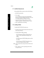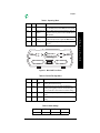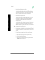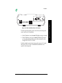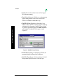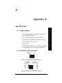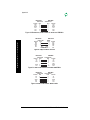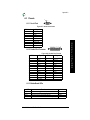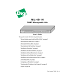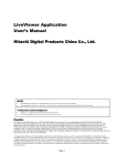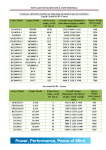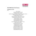
1
MIL-3200X Series of FastPort™
Print Servers
Hardware User’s Guide
with
FastManage™-Specific Information
Sunnyvale, California
Minnetonka, Minnesota
Legal
Trademark Rights
Digi International™, FastPort™, Print Server Software™, and the Digi logo are trademarks of Digi International, Inc. All other brand
and product names are the trademarks of their respective holders.
© Digi International, 1998. All Rights Reserved.
Information in this document is subject to change without notice and does not represent a commitment on the part of Digi
International.
Digi International provides this document “as is,” without warranty of any kind, either expressed or implied, including, but not
limited to, the implied warranty of fitness or merchantability for a particular purpose. Digi International may make improvements
and/or changes in this manual or in the product(s) and/or the program(s) described in this manual at any time.
This document could include technical inaccuracies or typographical errors. Changes are periodically made to the information herein;
these changes may be incorporated in new editions of the publication.
Restricted Rights
For non-U.S. Government use
These programs are supplied under a license. They may be used, disclosed, and/or copied only as permitted under such license
agreement. Any copy must contain the above copyright notice and this restricted rights notice. Use, copying, and/or disclosure of the
programs is strictly prohibited unless otherwise provided in the license agreement.
For U.S. Government use
Use, duplication, or disclosure by the Government is subject to restrictions as set forth in sub-paragraph (c)(1)(ii) of the Rights in
Technical Data and Computer Software clause of DFARS 52.227-7013.
The Digi Five-Year Limited Warranty
Digi International warrants to the original consumer or purchaser that each of its products, and all components thereof, will be free
from defects in material and/or workmanship for a period of five years from the original factory shipment date. Any warranty
hereunder is extended to the original consumer or purchaser and is not assignable.
Digi International makes no express or implied warranties including, but not limited to, any implied warranty of merchantability or
fitness for a particular purpose, except as expressly set forth in this warranty. In no event shall Digi International be liable for incidental
or consequential damages, costs, or expenses arising out of or in connection with the performance of the product delivered hereunder.
Digi International will in no case cover damages arising out of the product being used in a negligent fashion or manner.
Regulatory Approvals
•
•
•
•
•
FCC Class A
UL 1950
CSA 22 No. 950
EN60950
CE
– EN55022 Class B
– EN50082-1
Canadian EMI Notice
This Class A digital apparatus meets all the requirements of the Canadian Interference-Causing Equipment Regulations.
Cet appareil numérique de la classe A respecte toutes les exigences du Règlement sur le matériel brouilleur du Canada.
European Notice
Products with the CE Marking comply with both the EMC Directive (89/336/EEC) and the Low Voltage Directive (73/23/EEC) issued
by the commission of the European Community. Compliance with these directives implies conformity to the following European
Norms:
•
•
•
EN55022 (CISPR 22) - Radio Frequency Interference
EN50082-1 (IEC801-2, IEC801-3, IEC801-4) - Electromagnetic Immunity
EN60950 (IEC950) - Product Safety
To Contact Digi
For prompt response when calling for service information, have the following information ready:
•
•
•
Product serial number
Date of purchase
Vendor or place of purchase
You can reach Digi LAN technical support at 408/744-2751 or "[email protected]"
ii
Doc: # 90000069 Rev. C
Table of Contents
Preface
About this Manual ...............................................................................................
FastPort Documentation .....................................................................................
Contents of this Document.................................................................................
Notation Conventions .........................................................................................
Chapter 1:
P-1
P-1
P-2
P-2
Introduction
Overview of the MIL-3200X ...............................................................................
Versions of the MIL-3200X .................................................................................
Features .................................................................................................................
Shared Printer Features ...............................................................................
Utilities ...........................................................................................................
The Next Step .......................................................................................................
Chapter 2:
T
O
C
1-2
1-2
1-2
1-3
1-3
1-4
FastPort Installation
Installation Requirements................................................................................... 2-2
Installing FastPort................................................................................................ 2-2
Chapter 3:
MIL-4300M Series Micro Modules
Introduction ..........................................................................................................
Configuration .......................................................................................................
Versions of the Micro Modules..........................................................................
Installation ............................................................................................................
Chapter 4:
3-2
3-2
3-2
3-3
FastManage for the MIL-3200X
Overview of FastManage....................................................................................
Starting FastManage............................................................................................
MIL-3200X FastPort Graphical Icon ..................................................................
Configuration Pull-down Menu ........................................................................
Auxiliary Port Sub-Menu ............................................................................
MIL-3200X Series of FastPort Print Servers
4-2
4-2
4-3
4-4
4-4
iii
Table of Contents
Hot Spots............................................................................................................... 4-5
Appendix A:
Specifications
Hardware Features ..............................................................................................
Serial Printer and Terminal Cables ...................................................................
LEDs.......................................................................................................................
MotherBoard LEDs.......................................................................................
Parallel Port Connector................................................................................
Serial Port.......................................................................................................
RJ-45 Connector ............................................................................................
Pin outs: RJ-45 ........................................................................................
Micro Module Specifications .............................................................................
LEDs ...............................................................................................................
Serial Connector............................................................................................
T
O
C
Appendix B:
A-1
A-1
A-3
A-3
A-3
A-4
A-4
A-4
A-5
A-5
A-5
Technical Support Services
World Wide Web Server.....................................................................................
Internet FTP Server..............................................................................................
Contacting Technical Support ...........................................................................
Expediting Technical Support Service..............................................................
Returning Procedures .........................................................................................
B-1
B-1
B-2
B-2
B-2
Index
iv
MIL-3200X Series of FastPort Print Servers
P ref ac e
P.1
About this Manual
This manual has instructions on how to physically install a
MIL-3200X series of FastPort print server. This document also
has specific information on the FastManage™ suite of software
as it applies to the MIL-3200X.
The terms “MIL-3200X,” “FastPort” and “print server” are
used to describe the device throughout the document. This
document assumes that users are familiar with a system
administrator’s tasks.
P.2
FastPort Documentation
There are three separate manuals shipped with FastPort:
• MIL-3XXX FastPort Print Servers Hardware User’s Guide,
with FastManage-Specific Information. This document has the
following information:
– Instructions on how to physically set up FastPort
– Installation information on any “add-on” device
– Information on the FastManage suite of software and
how it may affect a specific FastPort
This document is unique to a specific FastPort print server.
• FastPort User’s Guide: This document has the following
information:
– The latest firmware information
– Software information for MS Windows™, Novell™, etc.
– Configuration and diagnostic information
This document is generic for all FastPorts.
MIL-3200X Series of FastPort Print Servers
P-1
P
R
E
F
A
C
E
Preface
• FastManage User’s Guide: Use this guide to setup the
FastManage software for FastPort.
This document is also generic for all FastPorts.
P.3
P
Contents of this Document
Material covered in this manual includes:
R
E
F
A
C
E
• Chapter 1: Provides an overview of MIL-3200X series
• Chapter 2: Provides instructions for installing FastPort
• Chapter 3: Provides installation information for the micro
modules
• Chapter 4: This section has specific information on
FastManage for the MIL-3200X
• Appendix A: Specifications for MIL-3200X series
• Appendix B: Technical support. How to contact Digi
P.4
Notation Conventions
This document has certain notation conventions that make it
easier to follow instructions and examples. Notation
conventions used in this manual are shown in Table P-1.
Table P-1: Notation Conventions
Conventions
Description
[Enter]
Brackets indicate a key to be pressed.
Courier bold
Courier boldface font indicates a system message, options, or
instructions to be implemented.
“+” sign
The “+” sign is used to indicate holding down one key while
pressing another (e.g., “press [Shift]+[C]”).
Italics
Italics designate variables and titles of other documents.
“Quick Reference”
Quotes refer to important information or titles.
CAPS
Capitalized words are either abbreviations, a specific directory,
or product markings.
P-2
MIL-3200X Series of FastPort Print Servers
Chapter 1
I n t ro du c tio n
Chapter 1 gives an overall description of the MIL-3200X
FastPort print server.
This chapter includes:
– “Overview of the MIL-3200X” on page 1-2
– “Versions of the MIL-3200X” on page 1-2
– “Features” on page 1-2
– “The Next Step” on page 1-4
MIL-3200X Series of FastPort Print Servers
1-1
I
N
T
R
O
D
U
C
T
I
O
N
Chapter 1
1.1 Overview of the MIL-3200X
The MIL-3200X series of FastPort print servers are 10 Mbps,
Ethernet and fiber optic print servers. The MIL-3200X allows
users to directly connect multiple printers on Ethernet
networks using their choice of network media, including:
I
N
T
R
O
D
U
C
T
I
O
N
• 10BASE-T, 10BASE2, and 10BASE5 for Ethernet
• 10BASE-FL for fiber optic media
1.2 Versions of the MIL-3200X
There are three different, pre-configured versions of the MIL3200X series of FastPort, including:
• MIL-3210X, for 10BASE-T connectivity using a MIL-4310M
micro module for its network connection
• MIL-3220X, for 10BASE2 connectivity using a MIL-4320M
micro module for its network connection
• MIL-3230X, for 10BASE-FL connectivity using a MIL4330M micro module for its network connection
Note:
For 10BASE5 connectivity, install a MIL-4340M micro module into any
the MIL-3200X (see to Chap. 3 for more info. on the micro modules)
1.3 Features
The MIL-3200X FastPort offers the following features:
• FastManage SNMP manager for Windows
• On-board diagnostic utilities can also be accessed on-line
• Apple Macintosh users can configure and modify each unit
by downloading configuration files with the supplied
LaserWriter™ utility
• Configuration can also be done manually or with the
supplied installation program
1-2
MIL-3200X Series of FastPort Print Servers
Chapter 1
1.3.1 Shared Printer Features
FastPort give users the widest access to shared printers:
• Windows 95®, Windows NT, and Windows for
Workgroups systems
I
N
T
R
O
D
U
C
T
I
O
N
• PCs networked with Novell® NetWare®
• UNIX® support
• Apple® Macintosh® using EtherTalk®
• OS/2® machines with TCP/IP
• PCs running a TCP/IP protocol stack over Ethernet
networks
• Microsoft LAN Manager® and IBM LAN Server® systems
The MIL-3200X print servers are configured by using an
SNMP management station, such as the FastManage software
(included). The MIL-3200X also supports SNMP MIB-II (RFCs
1213) and parallel and serial MIBs (RFCs 1318 and 1317).
1.3.2 Utilities
To make the units easier to manage, Digi supplies:
• FastManage suite of software, a Windows-based
management package
• Advanced Configuration Tool (ACT), a DOS-based menu
software application
Configuration of devices can be done by using print utilities
on UNIX systems. Firmware upgrades of the flash EPROMs
can be done via network connections. Refer to the FastPort
User’s Guide for more information.
MIL-3200X Series of FastPort Print Servers
1-3
Chapter 1
1.4 The Next Step
Use this guide to physically setup FastPort. Then consult the
FastPort User’s Guide for the latest software/firmware
installation information. Then refer to the FastManage User’s
Guide to configure FastManage for FastPort.
I
N
T
R
O
D
U
C
T
I
O
N
Note:
1-4
Chapter 4 in this document has FastManage information, but only as it
pertains to a specific FastPort. Chapter 4, though, does not have any
specific instructions on the FastManage suite of software.
MIL-3200X Series of FastPort Print Servers
Chapter 2
Fast Po r t In s ta lla tio n
Chapter 2 gives installation information for the FastPort print
server.
This chapter includes:
– “Installation Requirements” on page 2-2
– “Installing FastPort” on page 2-2
MIL-3200X Series of FastPort Print Servers
2-1
I
N
S
T
A
L
L
A
T
I
O
N
Chapter 2
2.1 Installation Requirements
Before installing FastPort, make sure you have the following:
• MIL-3200X series FastPort
• Power supply
Use a switchable power supply, such as the MIL-16DT
desk-top power adapter included with FastPort. Set for 120
VAC in the continental USA (Default is 220 VAC)
I
N
S
T
A
L
L
A
T
I
O
N
• Appropriate Ethernet cabling, which may include Tconnectors, terminators, external transceivers, or MAUs
• Serial or parallel printers with cabling
2.2 Installing FastPort
To install the MIL-3200X FastPort print server.
1. Record the Ethernet address (located on the bottom of the
unit) for future reference
2. Attach the Ethernet cabling, including:
– MIL-3210X supports 10BASE-T cabling directly; use
category 5 (CAT 5) unshielded twisted pair (UTP)
cabling.
– MIL-3220X supports 10BASE2 cabling directly; use thin
net cabling.
– MIL-3230X supports 10BASE-FL cabling directly; use
multi-mode or single-mode fiber cabling.
Note:
Install a micro module for any other type of network connection, refer to
Chapter 3.
3. Refer to Table 2-1 to select an operating mode with the
front panel switches.
2-2
MIL-3200X Series of FastPort Print Servers
Chapter 2
Table 2-1: Operating Mode
D3
D4
Mode
Description
Up
Up
Normal
Does not allow a Telnet session. Users can print to the
unit. The SYS (system) LED and NET (network) LED blink.
Down
Up
Telnet Diagnostic Allows a Telnet session to monitor FastPort or change its
Monitor
parameters. Users can print to the unit. The SYS LED and
NET LED blink.
Down
Down
Serial Diagnostic
Monitor
A terminal can be attached to serial port 2 to run a serial
monitor. Print jobs are not accepted. The NET LED blink.
Up
Down
Test Page
A test page prints on a power cycle. No print jobs are
accepted.
1 SERIAL
PARALLEL
TM
FASTPORT
SERIAL
PARALLEL
2
4 PORT NETWORK PRINT SERVER
MODEL MIL•3200X
S1
P2
S2
1
2
3
4
P1
Figure 2-1. MIL-3200X Front Panel
Table 2-2: Flash and Test Page Select
Switch
D1
Position
Up
Mode
Description
Flash
Bank
Selects bank 0 (upper) to run the 4 Mb Flash EPROMs for
uploading the new firmware image.
Down
D2
Up
Selects bank 1 (lower) to run the 4 Mb Flash EPROMs for
uploading. If the upgrade process fails, use this setting and
power cycle the unit to return FastPort to its default settings.
Test Page
Down
MIL-3200X selects parallel port 2 and serial port 2 for test page
printing.
MIL-3200X selects parallel port 1 and serial port 1 for test page
printing.
Table 2-3: Default Settings
D1
Up
D2
Down
MIL-3200X Series of FastPort Print Servers
D3
Down
D4
Up
2-3
I
N
S
T
A
L
L
A
T
I
O
N
Chapter 2
4. Attach the parallel printer(s) cables.
Attach the parallel cable to the female DB25 parallel port
on the front of the FastPort. Connect the other end of the
cable to a standard, centronics port on the printer.
5. Attach the serial printer cables.
I
N
S
T
A
L
L
A
T
I
O
N
Attach a serial cable to the male DB9 printer port on the
front of the unit. The other end of the cable should be
connected to a female DB9 with the standard serial
interface pinout.
A null modem cable or adapter is necessary if the printer’s
serial port is a DTE device. If the cable will work for an
IBM PC attached to a printer, then it will work for FastPort.
Note:
See Appendix A for serial port pinouts.
6. Set the printer to the defaults for the serial port: 9600 baud,
8 data bits, no parity bits, 1 stop bit, and Xon/Xoff for flow
control.
7. Connect the power supply and verify normal boot-up:
a. Select the proper voltage for the specific country
b. Place the unit near the printer
c. Plug the power connector into the receptacle marked
16VAC on the rear of the unit
2-4
MIL-3200X Series of FastPort Print Servers
Chapter 2
FT
RX
PW
CX
MIL•4320M
16VAC
PWR
SYS NET LNK
UTP
Figure 2-2. MIL-3210X Rear Panel of FastPort
The unit performs POST (power-on self-test) at start-up and
tries to resolve its IP addresses.
• If the IP address is set, the SYS LED blinks once per second.
• If the IP address is not set, the SYS LED blinks five times
per second until the address is set either manually or by
using RARP, BOOTP, or DHCP.
FastPort should now be functioning on the network. Consult
the FastPort User’s Guide to continue the installation on a
specific client computer.
MIL-3200X Series of FastPort Print Servers
2-5
I
N
S
T
A
L
L
A
T
I
O
N
Chapter 2
I
N
S
T
A
L
L
A
T
I
O
N
2-6
MIL-3200X Series of FastPort Print Servers
Chapter 3
M
I
C
R
O
MIL-4300M Series Micro Modules
M
O
D
U
L
E
S
Chapter 3 gives installation information for the MIL-4300M
series of micro modules. For more information on micro
modules, refer to the MIL-4300M Series of Micro Modules
Installation Guide.
The chapter includes:
– “Introduction” on page 3-2
– “Configuration” on page 3-2
– “Versions of the Micro Modules” on page 3-2
– “Installation” on page 3-3
MIL-3200X Series of FastPort Print Servers
3-1
Chapter 3
3.1 Introduction
Each version of the MIL-3200X has its own type of micro
module for its network connection:
• MIL-3210X: Has the MIL-4310M micro module on-board.
The MIL-4310M has an RJ-45 connector (Unshielded
twisted pair).
M
I
C
R
O
• MIL-3220X: Has the MIL-4320M micro module on-board.
The MIL-4320M has a BNC connector (thin COAX).
M
O
D
U
L
E
S
Each micro module can be swapped so that the user can
change the network connection. However, always power
down the device before swapping a micro module. FastPort is
not capable of “hot-swappable” maneuvers.
• MIL-3230X: Has the MIL-4330M micro module on-board.
The MIL-4330M has an ST connector (fiber optic).
3.2 Configuration
The micro modules come with five different type of
connectors: RJ-45, ST, SMA, AUI, and thin COAX (BNC). Refer
to the MIL-4300M Series of Micro Modules Installation Guide for
configuration and specification information.
3.3 Versions of the Micro Modules
Versions of MIL-4300M series of micro modules supported by
the MIL-3200X series, includes:
• MIL-4310M: 10BASE-T, with an RJ-45 connector (versions
C, D and E)
• MIL-4320M: 10BASE2, with a COAX (BNC) connector
(versions A and B)
• MIL-4330M: 10BASE-FL multi-mode, with an ST connector
(versions A and B)
3-2
MIL-3200X Series of FastPort Print Servers
Chapter 3
• MIL-4340M: 10BASE5, with an AUI connector (version B)
• MIL-4350M: 10BASE-FL multi-mode, with an SMA
connector (versions A, B and C)
• MIL-4360M: Single-mode, half-duplex; with an ST
connector (versions A and B)
• MIL-4370M: Single-mode, half- and full-duplex; with an ST
connector (versions A and B)
FT
M
I
C
R
O
RX
Vacant Slot
PW
CX
MIL•4320M
16VAC
M
O
D
U
L
E
S
PWR SYS NET LNK
UTP
FT
RX
LK
CX
Figure 3-1. MIL-4300M Micro Module
3.4 Installation
Do the following to install any of the following micro module:
1. Use a phillips head screwdriver to remove the screws
securing the faceplate of the base unit.
2. Remove the faceplate.
3. Make any configuration changes to the module.
4. Slide the module into the port.
MIL-3200X Series of FastPort Print Servers
3-3
Chapter 3
5. Insert the module into the card-edge connector (port bay).
Make sure it is seated firmly.
6. Secure with the #4-40 X 3/16” phillips-type screws.
With the micro module now installed and ready to use, the
user can install the proper network connection.
M
I
C
R
O
M
O
D
U
L
E
S
3-4
MIL-3200X Series of FastPort Print Servers
Chapter 4
FastManage for the MIL-3200X
Chapter 4 discusses FastManage-specific software; however,
only as it applies to the MIL-3200X series of FastPort print
servers. This chapter does not give detailed instructions on the
software. Refer to the FastManage User’s Guide for installation
and configuration instructions for the FastManage suite of
software.
This chapter includes:
– “Overview of FastManage” on page 4-2
– “Starting FastManage” on page 4-2
– “MIL-3200X FastPort Graphical Icon” on page 4-3
– “Configuration Pull-down Menu” on page 4-4
– “Hot Spots” on page 4-5
MIL-3200X Series of FastPort Print Servers
4-1
F
A
S
T
M
A
N
A
G
E
Chapter 4
4.1
Overview of FastManage
The FastManage suite of software allows configuration and
network management for most SNMP-type devices, including
print servers, fax servers, hubs, and stackable hubs.
When the software is started, an icon appears that represents
each SNMP device. This section discusses the specific icon for
this specific FastPort: the MIL-3200X FastPort print servers.
Note:
F
A
S
T
M
A
N
A
G
E
4.2
This section only has an overview of the software for a specific Digi
SNMP device.
Starting FastManage
There are two ways to start the FastManage suite of software:
• Discover icon:
a. Start by double-clicking on the Discovery icon. The
system “discovers” all of the SNMP manageable
devices on the subnet.
Figure 4-1. FastManage for FastPort
4-2
MIL-3200X Series of FastPort Print Servers
Chapter 4
b. The devices will now appear on Map 1 as “thumbnails,”
which represents each SNMP device.
c. Double-click on a thumbnail to display a full-screen
image of that particular SNMP device (see Figure 4-2).
• FastPort PrintServer Mgr. Icon:
a. Also start the software by double-clicking on the
FastPort PrintServer Mgr. icon.
b. Enter the IP Address of the device.
c. A full-screen image of that device appears (Figure 4-2).
4.3
MIL-3200X FastPort Graphical Icon
The following appears when the MIL-3200X is retrieved:
Pull-Down
Menus
Hot Spot
Figure 4-2. MIL-3200X Graphical Icon
MIL-3200X Series of FastPort Print Servers
4-3
F
A
S
T
M
A
N
A
G
E
Chapter 4
4.4
Configuration Pull-down Menu
There are many different options available from the pull-down
menus, including TCP/IP, Novell, and SMB configurations.
Refer to the FastManage User’s Guide for more information.
4.4.1 Auxiliary Port Sub-Menu
The “Auxiliary Port” sub-menu (Figure 4-3) differs from other
FastPorts, because the MIL-3200X series has two serial and
two parallel ports. To view the “Auxiliary Port” sub-menu
from the “Configuration” pull-down menus, go to:
F
A
S
T
M
A
N
A
G
E
TCP/IP Config.--> fpfilter Configuration-->Auxiliary ports
Figure 4-3. Auxiliary Port Menu
This parameter specifies an auxiliary port for parallel or serial
port printing.
4-4
MIL-3200X Series of FastPort Print Servers
Chapter 4
4.4.2 Parallel/Serial Printer Setup Sub-Menu
Again, both the “Parallel Printer Setup” (Figure 4-4) and the
“Serial Printer Setup” sub-menus differ from other FastPorts,
because the MIL-3200X series has two serial and two parallel
ports. To view these sub-menus from the “Configuration”
pull-down menu, go to:
Ethertalk Config.-->Parallel Printer Setup/Serial Printer Setup
(Figure 4-4)
F
A
S
T
M
A
N
A
G
E
Figure 4-4. Parallel Printer Setup Menu
This parameter sets-up the port for parallel or serial port
printing. Printer 1, Printer 2, Serial 1 and Serial
2 are your choices.
4.5
Hot Spots
Hot spots on the graphical representation of the MIL-3200X
series (Figure 3-2) are used to gain status of the device. Use the
mouse to highlight the selection (a block around the area will
appear), and click on it to obtain the information.
Hot spots function the same way on all FastPorts, even though
they may appear in different locations. The following
describes the hot spots applicable for the MIL-3200X. Refer to
the FastManage User’s Guide for more information.
• Traps: This selection alerts the user to any problem
associated with the device.
MIL-3200X Series of FastPort Print Servers
4-5
Chapter 4
• Uptime: This selection informs the user of how long the
device has been running.
• Reset: When this hot spot is clicked on, a warning message
appears asking whether or not the user want to reset
FastPort. Select Yes to continue, No to stop.
• Digi/MiLAN Logo: Depending on the model of your
FastPort, either a “MiLAN” or a “Digi” appears on the top,
right-hand side of the graphic. When this Logo is clicked
on, FastPort specifications appear. Reset Name, Location,
and Contact. Press Set after the changes are made
(Figure 4-5).
F
A
S
T
M
A
N
A
G
E
Figure 4-5. Digi/MiLAN Logo Message
• Parallel Port: Depending on which button is clicked, this
parameter displays the status of the Parallel port.
• Serial Port: Depending on which mouse button is clicked,
this parameter displays the status of the Serial port.
4-6
MIL-3200X Series of FastPort Print Servers
Appendix A
S p eci fic a tio n s
A.1
Hardware Features
• The 3200X motherboard, with Ethernet controller, serial
port, parallel port interfaces
• CPU: An Intel 80186 processor, with a 16 MHz clock
• Flash: Flash devices are 29F040. Each device are 4 Mbps
and arranged in 2 × 256k × 8 format.
• Memory: 1 MB
• MAC chipsets: Ethernet controller is 10 Mbps, with DRAM
for data buffering, and its own memory management
A.2
Serial Printer and Terminal Cables
Print Server
Side
2
3
5
7
8
PC
3
2
5
8
7
Figure A-1.Common Dumb Terminal Connection
DB9 Female
FastPort Side
Function
Pin #
RXD
2
TXD
3
GRND
5
RTS
7
CTS
8
DTR
4
DB25 Male
Terminal/Printer
Pin #
Function
2
TXD
3
RXD
7
GRND
5
CTS
4
RTS
6
DSR
Figure A-2.Cable for Terminal and Serial Printers
MIL-3200X Series of FastPort Print Servers
A-1
S
P
E
C
I
F
I
C
A
T
I
O
N
S
Appendix A
DB9 Female
FastPort Side
Function Pin #
RXD
2
TXD
3
GRND
5
RTS
7
CTS
8
DTR
4
DB25 Male
Terminal/Printer
Pin #
Function
2
TXD
3
RXD
7
GRND
5
CTS
4
RTS
6
DSR
Figure A-3.DCE Device, Dumb Terminal or Serial Port: DB9 Male
DB9 Female
FastPort Side
Function
Pin #
RXD
2
TXD
3
GRD
5
RTS
7
CTS
8
S
P
E
C
I
F
I
C
A
T
I
O
N
S
DB9 Female
IBM PC
Pin #
2
3
5
7
8
Function
TXD
RXD
GRD
CTS
RTS
Figure A-4.Wyse 60 Dumb Terminal
DB9 Female
FastPort Side
Function
Pin #
RD
2
TD
3
DTR
4
SGND
CTS
5
8
DB25 Male
Terminal/Printer
Pin #
Function
2
TD
3
RD
5
CTS
6
DSR
7
SGND
20
DTR
Figure A-5.DTE Printer/Plotter and PC Null: DB25 Male
DB9 Female
FastPort Side
Function
Pin #
RD
TD
SGND
RTS
CTS
2
3
5
7
8
DB25 Male
Terminal/Printer
Pin #
Function
3
2
7
4
5
TD
RD
SGND
RTS
CTS
Figure A-6.DCE Printer/Plotter: DB25 Female
A-2
MIL-3200X Series of FastPort Print Servers
Appendix A
A.3
Pinouts
1
2 3 4 5
A.3.1 Serial Port
6 7 8 9
Figure A-7.Serial Port Pinouts
PIN Number
1
2
3
4
5
6
7
8
9
Signal
NC
RXD
TXD
DTR/RTS
GND
NC
RTS/DTR
CTS
NC
13 12 11 10 9 8 7 6 5 4 3 2
A.3.2 Parallel Port Connector
S
P
E
C
I
F
I
C
A
T
I
O
N
S
1
25 24 23 22 21 20 19 18 17 16 15 14
Figure A-8. Parallel Port Pinouts
PIN #
1
2
3
4
5
6
7
8
9
10
11
12
13
Signal
PASTB
PAD0
PAD1
PAD2
PAD3
PAD4
PAD5
PAD6
PAD7
ACK
BUSY
PE
ONLINE
PIN #
14
15
16
17
18
19
20
21
22
23
24
25
Signal
AUTO FEED
FAULT
INIT
SLCTIN
GND
GND
GND
GND
GND
GND
GND
GND
A.3.3 MotherBoard LEDs
LED
PWR
SYS
NET
LNK
Functioned
Unit is receiving power
Indicate whether or not the IP address is correct
There is activity on the network port
There is an active connection on the UTP port
MIL-3200X Series of FastPort Print Servers
Color
Green
Green
Yellow
Green
A-3
Appendix A
A.3.4 RJ-45 Connector
• Pin 1: Transmit data +
3 4
1 2
• Pin 2: Transmit data -
5 6 7 8
• Pin 3: Receive data +
• Pin 6: Receive data -
A.4
Micro Module Specifications
A.4.1 LEDs
S
P
E
C
I
F
I
C
A
T
I
O
N
S
The MIL-3200X is shipped standard with the MIL-4340M
micro module. The following are the LEDs and what they
indicate. Consult the MIL-4300M Series of Micro Modules
Installation Guide for the correct LED and other information.
Table A-1: MIL-4340 Indicators
LED
PWR
FT
CX
RX
Functioned
Unit is receiving power
The segment has faulted
Collision is occurring on the network
Unit is receiving packets from the network
Color
Green
Red
Red
Yellow
A.4.2 Serial Connector
PIN Number
1
2
3
4
5
6
7
8
A-4
Signal
M2
CX+
TX+
M2
RX+
GND
M0
M1
PIN Number
9
10
11
12
13
14
15
16
Signal
CDTXCR
RX20V
VCC
LC
LF
MIL-3200X Series of FastPort Print Servers
Appendix B
Tech nic a l Su p p o r t S e r v ic e s
B.1
World Wide Web Server
Product information, manuals, new product announcements,
programs, applications stories and more can be obtained
through the world wide web. Our address is:
http://www.dgii.com
B.2
Internet FTP Server
Digi has set up an anonymous FTP server for those with access
to the internet. The address is ftp.milan.com or
206.40.59.2. Log-in as anonymous, and enter an email
address when asked for a password. Drivers and installation
tips are located in the /pub/fastport/software and /pub/
fastport/faq directories.
Note:
To ensure binary transfer of files, switch to binary mode by entering bin
or binary before downloading.
MIL-3200X Series of FastPort Print Servers
B-1
T
E
C
H
S
U
P
P
O
R
T
Appendix B
B.3
Contacting Technical Support
To contact Digi’s technical support:
B.4
• By Phone:
408/744-2751
• By Fax:
408/744-2771
• By email:
[email protected]
Expediting Technical Support Service
For faster service when calling our technical support
department:
• Be in a position where the computer and the print server
are accessible
T
E
C
H
• Know the type and versions of software you are using.
• Know your hardware specification, including memory and
disk space.
S
U
P
P
O
R
T
• Note any and all error messages.
• Be specific about the problem(s).
B.5
Returning Procedures
To return a unit to Digi:
1. Call technical support at 408/744-2751
2. Technical support engineers will work with users to find
the problem. If technical support determines that the unit is
defective, a return materials authorization (RMA) will be
issued by our RMA administrator who will also provide
shipping instructions.
Note:
B-2
It is required that any return has an RMA number or it will be rejected
and returned to the sender.
MIL-3200X Series of FastPort Print Servers
Index
Numerics
1 stop bit 2-4
10BASE2 1-2, 2-2
10BASE5 1-2
10BASE-FL 1-2, 2-2
10BASE-T 1-2, 2-2
120 VAC 2-2
16 MHz clock A-1
16VAC 2-4
220 VAC 2-2
8 data bits 2-4
9600 baud 2-4
A
Advanced Configuration Tool (ACT) 1-3
F
FastManage 4-1
Overview 4-2
Parallel Port 4-6
Reset 4-6
Serial Port 4-6
Traps 4-5
Uptime 4-6
FastManage User’s Guide P-2, 1-4, 4-1
FastPort Installation 2-1
FastPort User’s Guide P-1, 1-3, 1-4, 2-5
Fiber optic 3-2
Flash Bank 2-3
Flash device A-1
Flash EPROMs 1-3
ftp.milan.com B-1
H
Hardware Features A-1
Hot Spots 4-5
http
//www.dgii.com B-1
B
I
N
D
E
X
I
BNC connector 3-2
C
Configuration options 4-4
Connectors
AUI 3-2
BNC 3-2
RJ-45 3-2
ST (SMA) 3-2
D
DB25 parallel port 2-4
DB9 printer port 2-4
Digi/MILAN Logo 4-6
Discovery 4-2
DRAM A-1
DTE device 2-4
E
Ethernet 1-2, 2-2, A-1
EtherTalk 1-3
MIL-3200X Series of FastPort Print Servers
IBM LAN Server 1-3
Installation
FastPort 2-2
Intel 80186 CPU A-1
Internet access B-1
Internet FTP Server B-1
IP address 2-5
L
LEDs
Micro Modules A-5
Motherboard A-3
M
MAC chipsets A-1
Micro Module 3-1
Installation 3-3
Introduction 3-2
Specifications A-5
Microsoft LAN Manager 1-3
MIL-16DT 2-2
I-1
Index
MIL-3200X 1-1, 2-2, 4-1, 4-2, 4-3
Features 1-2
Front Panel 2-3
Overview 1-2
MIL-4300M
Micro Modules 3-1
MIL-4310M 1-2, 3-2
MIL-4320M 1-2, 3-2
MIL-4330M 1-2, 3-2
MIL-4340M 1-2, 3-3
MIL-4350M 3-3
MIL-4360M 3-3
MIL-4370M 3-3
N
NetWare 1-3
No parity bits 2-4
Notation Conventions P-2
Novell P-1, 1-3, 4-4
Null modem cable 2-4
O
I
N
D
E
X
Operating Mode 2-3
P
Parallel Port Connector A-3
Parallel printer 2-4
Power supply 2-2
ST connector 3-2
[email protected] B-2
T
TCP/IP 1-3, 4-4
TCP/IP Config.
Auxiliary ports 4-4
fpfilter Configuration 4-4
Technical Support B-1, B-2
Telnet Diagnostic Monitor 2-3
Test Page 2-3
Thin COAX 3-2
Thumbnail 4-3
U
UNIX 1-3
Unshielded twisted pair 3-2
Utilities 1-3
W
World Wide Web Server B-1
X
Xon/Xoff 2-4
R
RARP 2-5
Return Materials Authorization (RMA) B-2
RJ-45 3-2, A-4
S
Serial Diagnostic Monitor 2-3
Serial Port A-4
Serial port defaults 2-4
Serial printer 2-4
Serial Terminal Cable A-1
SMA 3-2
SMB 4-4
SNMP 1-2, 1-3, 4-2
Specifications
Hardware Features A-1
I-2
MIL-3200X Series of FastPort Print Servers
1299 Orleans Drive
Sunnyvale, CA 94089
Part Number: 90000069 Rev. C
Printed in the USA