1
530.46-N2Y
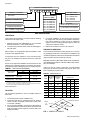
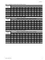
PRODUCT NOMENCLATURE
D
1
E H
0
2
4
A
0
6
PRODUCT CATEGORY
D = Single Package Air Conditioner
(Air Cooled)
VOLTAGE CODE
06 = 208/230-1-60
25 = 208/230-3-60
46 = 460-3-60
58 = 575-3-60
NOMINAL COOLING
CAPACITY (MBH)
018 = 18,000 BTUH
024 = 24,000 BTUH
030 = 30,000 BTUH
036 = 36,000 BTUH
042 = 42,000 BTUH
048 = 48,000 BTUH
060 = 60,000 BTUH
PRODUCT GENERATION
1 = NEW or Current Design
PRODUCT IDENTIFIER
EH = 12 SEER Cooling Models
EM = 13 SEER Cooling Models
FACTORY
INSTALLED ELECTRIC HEAT
A = No Electric Heat Installed
INSTALLATION
LIMITATIONS
These units must be installed in accordance with the following
national and local safety codes.
1. National Electrical Code ANSI/NFPS No. 70 or Canadian
Electrical Code Part 1, C22.1 (latest editions).
2. Local plumbing and waste water codes and other applicable local codes.
Refer to Table 1 for unit application data and to Tables 5 and 6
for electric heat application data.
If components are to be added to a unit to meet local codes,
they are to be installed at the dealer’s and/or the customer’s
expense.
Size of unit for proposed installation should be based on heat
loss/heat gain calculations made in accordance with industry
recognized procedures identified by the Air Conditioning Con-
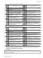
TABLE 1 - UNIT APPLICATION DATA
208/230V3
460V
575V
Wet Bulb Temperature (°F) of Air on
Evaporator Coil,
Min. / Max.
Dry Bulb Temperature (°F) of Air on
Condenser Coil, Min.2 / Max.
Voltage Variation
Min. / Max.1
187 / 2533
414 / 504
518 / 630
57 / 72
45 / 120
1 Rated in accordance with ARI Standard 110, utilization range "A".
2
A low ambient accessory is available for operation down to 0°F
3
“T1" transformer primary tap must be moved from the 230 volt connection to the 208 volt
connection for low voltage applications of 208 volt and below.
tractors of America.
LOCATION
Use the following guidelines to select a suitable location for
these units.
4. For roof top installation, be sure the structure will support
the weight of the unit plus any field installed components.
Unit must be installed on a level roof curb or appropriate
angle iron frame providing adequate support under the
compressor/condenser section.
5. Maintain level tolerance of unit to 1/8" maximum.
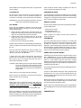
RIGGING OR HANDLING
Care must be exercised when moving the unit. Do not remove
any packaging until the unit is near the place of installation. Rig
unit with slings placed under the unit. Spreader bars of sufficient
length should be used across the top of the unit.
BEFORE LIFTING A UNIT, MAKE SURE THAT ITS WEIGHT
IS DISTRIBUTED EQUALLY ON THE CABLES SO THAT IT
WILL LIFT EVENLY.
Units may also be moved or lifted with a fork-lift. Slotted
openings in the skid are provided for this purpose. Forks must
pass completely through the base.
TABLE 2 - UNITS WEIGHTS
UNIT
SIZE
SHIPPING OPERATING
WEIGHT
WEIGHT
(lbs.)
(lbs.)
3. For ground level installation, a level pad or slab should be
used. The thickness and size of the pad or slab used should
meet local codes and unit weight. Do not tie the slab to the
building foundation.
"A"
"B"
"C"
"D"
018
330
325
89
78
76
86
024
338
333
91
80
78
88
030
340
335
86
83
83
87
036
341
336
92
81
79
89
042
348
343
94
83
80
91
048
376
371
94
89
94
99
060
456
451
127
122
101
106
1. Unit is designed for outdoor installation only.
2. Condenser must have an unlimited supply of air. Where a
choice of location is possible, position unit on either north
or east side of building.
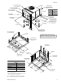
CORNER WEIGHTS
(location, lbs.)
"D"
CENTER OF GRAVITY
FRONT
OF
UNIT
"A"
"C"
"B"
491⁄8
26
231⁄2
471⁄4
FIG. 1 - CENTER OF GRAVITY
2
Unitary Products Group