1
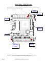
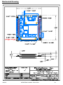
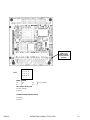
OPERATIONS MANUAL PPM-GX500 NOTE: This manual has been designed and created for use as part of WinSystems Technical Manuals CD and/or the WinSystems website. If this manual or any portion of the manual is downloaded, copied or emailed, the links to additional information (i.e. software, cable drawings) may be inoperable. WinSystems reserves the right to make changes in the circuitry and specifications at any time without notice. Copyright 2008 by WinSystems. All Rights Reserved. REVISION HISTORY P/N 400-0326-000 ECO Number Date Code ORIGINATED 07-144 08-10 08-61 070402 070711 070924 080226 080505 Rev Level Draft A A.1 A.2 A.3 Table of Contents Visual Index – Quick Reference Top View - Connectors Bottom View Top View - LEDs i i ii iii Introduction 1 General Information Features Software Support 1 1 3 Functional Capability System Processor Memory DMA Interrupt Routing Interrupt Status Register Power and Reset Interface Power Fail Reset BIOS Real-Time Clock/Calendar Battery Backup Rotational Disk Support Solid State Disk (SSD) Support Serial Interface Serial Connector Summary (DB9 Pinout) for all four ports Video Interface Ethernet Controller Audio Interface GPS Interface Line Printer Port Keyboard Mouse Interface USB Watchdog Timer Status LED Speaker PC/104 Bus Interface PC/104-Plus Bus Interface PC/104-Plus VIO Voltage 4 4 4 4 4 4 5 5 6 6 6 7 7 7 8 9 10 11 11 12 12 12 12 13 13 13 14 15 15 BIOS Supplemental 16 Serial Console Reference 30 I/O Port Map 35 Interrupt Map 36 Cables 37 Software Drivers & Examples 38 Mechanical Drawing 39 Jumper Reference 40 Specifications 42 WARRANTY REPAIR INFORMATION 43 Visual Index – Quick Reference Top View - Connectors For the convenience of the user, a Visual Index has been provided with direct links to connector and jumper configuration data. J7 POWER CONNECTOR J4, J6 PC/104 CONNECTORS J2 CFLASH SOCKET J8 MULTI I/O CONNECTOR SP1 SPEAKER J1 CMOS; EEROM ACCESS; BATTERY ENABLE; WATCHDOG (JUMPER) J5 PC/104-Plus CONNECTOR NOTE: The reference line to each component part has been drawn to Pin 1, where applicable. Pin 1 is also highlighted with a red square, where applicable. 080505 OPERATIONS MANUAL PPM-GX500 Visual Index – Quick Reference Bottom View For the convenience of the user, a Visual Index has been provided with direct links to connector and jumper configuration data. J106 BACKLIGHT CONNECTOR J101 FLAT PANEL CONNECTOR J109 IDE; FLOPPY CONNECTOR J102 AUDIO CONNECTOR J103 USB CONNECTOR J104 CRT CONNECTOR J105 CRT/FLAT PANEL; FLAT PANEL POWER; CFLASH MASTER (JUMPER) J108 GPS CONNECTOR J107 SODIMM SOCKET NOTE: The reference line to each component part has been drawn to Pin 1, where applicable. Pin 1 is also highlighted with a red square, where applicable. 080505 OPERATIONS MANUAL PPM-GX500 ii Visual Index – Quick Reference Top View - LEDs For the convenience of the user, a Visual Index has been provided with direct links to connector and jumper configuration data. D5 STATUS LED D4 IDE STATUS LED D1 ETHERNET SPEED D2 ETHERNET LINK D3 ETHERNET ACTIVITY NOTE: The reference line to each component part has been drawn to Pin 1, where applicable. Pin 1 is also highlighted with a red square, where applicable. 080505 OPERATIONS MANUAL PPM-GX500 iii Introduction This manual is intended to provide the necessary information regarding configuration and usage of the PPM-GX500 board. WinSystems maintains a Technical Support Group to help answer questions regarding usage or programming of the board. For answers to questions not adequately addressed in this manual, contact Technical Support at (817) 274-7553, Monday through Friday, between 8 AM and 5 PM Central Standard Time (CST). General Information Features Processor • AMD GeodeTM [email protected] Operating Systems Supported • x86 RTOS, XP Embedded, Linux, DOS, Windows CE, XP Memory • Up to 512 MB of 200-pin SODIMM PC2700 DDR SDRAM (Socketed) Video • CRT or Flat Panel operation (simultaneous operation not supported) • Up to 1600x1200 CRT resolution • Up to 1024x768 Flat Panel resolution • Up to 18-bits/pixel color panel support • LVDS Supported Ethernet • Intel 82551ER 10/100 Mbps controller Serial I/O • Four (4) serial ports (2-RS-232, 2-RS-232/422/485) Line Printer Port • EPP/ECP supported USB • Two (2) USB 1.1 ports Interrupts • Two (2) interrupt controllers • Seven (7) DMA channels Watchdog Timer • Up to 300 second reset CompactFlash • Types I & II supported IDE • One (1) Ultra DMA/66 IDE port supports up to two (2) devices 080505 OPERATIONS MANUAL PPM-GX500 Floppy Drive • Two (2) 3.5” drives supported Power • +5V @ 1.5A required Industrial Operating Temperature Range • -40°C to 85°C Form Factor • PC/104-Plus-compliant • 3.60” x 3.80” (90 mm x 96 mm) Additional Specifications • RoHS compliant • PC/104 and PC/104-Plus expansion connectors • AMD XpressROM BIOS • Backlight power supported • Custom splash screen on start up • Real-time clock • Activity status LEDs on-board • AC97 Support • PS/2 Keyboard Supported • PS/2 Mouse Supported 080505 OPERATIONS MANUAL PPM-GX500 The PPM-GX500 is an AMD Geode [email protected], PC/104-Plus single board computer (SBC). AMD Geode processors have extremely low power dissipation which allows fanless operation. The board accepts up to 512 MB of PC2700 DDR SDRAM. Also, a 10/100 Ethernet controller, video with CRT and flat panel interfaces, four serial COM channels, AC97 audio, and the standard AT peripheral feature set are included. It supports two floppy disk drives and two Ultra DMA 33/66 IDE drives. Additionally, the PPM-GX500 has two USB 1.1 channels that support USB keyboard, mouse, floppy and storage devices. Legacy USB operation is supported by the system BIOS. Booting from a USB port is supported. The PPM-GX500 measures 3.60” x 3.80” (90 mm x 96 mm). It offers additional I/O expansion with PC/104 and PC/104-Plus connectors. There is a socket for bootable Type I and II CompactFlash cards. A connector is included to support a remote GPS receiver. The board will operate from -40°C to +85°C , without requiring a fan, for rugged embedded applications. It is ideal for low-power, high-performance, battery powered and portable applications. Software Support The PPM-GX500 is an x86-compatible SBC. It is designed to run both 16-bit and 32-bit x86 instruction set software and is compatible with Microsoft’s Windows CE and XP Embedded (XPe) operating systems as well as the applications that run on them. It also supports Linux, DOS and many other PC-compatible x86 operating systems such as QNX, VxWorks or other real-time executives that require a PC hardware environment. Software Developers Kit -WinSystems offers software developers kits to provide the necessary hardware, software and cables to aid program development with the PPM-GX500 board. The configuration consists of an operating system, DVD-ROM drive, a hard disk, a 3.5” floppy disk, plus required cables and triple output power supply housed in an enclosure. This packaging permits easy access to the board, PC/104 modules and peripherals during program development. 080505 OPERATIONS MANUAL PPM-GX500 Functional Capability System Processor The PPM-GX500 board is based upon an AMD Geode™ GX500 and the CS5535 companion chip. These devices incorporate the CPU, 32 KB of cache, FPU, DDR SDRAM controller, Flash/ROM controller, an integrated display controller, audio controller, PCI controller and the RTC/CMOS RAM. The AMD processor runs at 367 MHz with a typical power consumption of 1.1W, allowing operation in extended temperature environments. AMD Geode Solutions assigns model numbers to better reflect total performance beyond just the clock speed. The Geode GX500 model number reflects performance as a 500 MHz processor. The processor is not user replaceable or upgradeable. Memory The PPM-GX500 can support a maximum of 512 MB of RAM with the SODIMM socket located on the back of the board at J107. Visual Index Qualified SODIMMS are available directly from WinSystems. WinSystems cannot warrant the operation of systems using nonqualified SODIMM modules. The RAM can be user supplied, but must meet the following criteria: 200-Pin SODIMM PC2700 DDR SDRAM with gold fingers (up to 512 MB) Installation is accomplished by inserting the module into the connector at approximately a 30 degree angle. Press firmly to fully seat the module into the connector and then press the module downward to snap it into the retaining clamps. Removal is accomplished by gently pulling outward on the retaining clamps until the module springs up to the appropriate removal angle. DMA DMA is supported. Channel 2 is dedicated to the floppy disk controller. The LPT is plug-and-play configurable. The other 8-bit DMA channels are wired to the PC/104 connector. 16-bit channels 5, 6 and 7 are not supported on the AMD GX500™ processor. Interrupt Routing Two 82C59A-compatible interrupt controllers accept inputs from the on-board peripherals and the PC/104 Bus connectors. The configuration of interrupt inputs is achieved in the BIOS CMOS setup discussed in the BIOS Supplemental later in this manual. Interrupt Status Register One of the unique features of the PPM-GX500 is the Interrupt Status Register located at 1ECH. This read-only register allows some on-board devices to share interrupts and thus free interrupts for other peripherals. It is the same technique used to share interrupts on multiport serial cards. If two devices are configured in the BIOS to use the same interrupt, the Interrupt Status Register can be read to determine which device generates an interrupt. Once a pending interrupt is serviced, the status register should be read again to see if another interrupt is pending before exiting the routine. 080505 OPERATIONS MANUAL PPM-GX500 WinSystems does not provide software support for implementing the Interrupt Status Register to share interrupts. Some operating systems, such as Windows XP and Linux, have support for sharing serial port interrupts and examples are available. The user will need to implement the appropriate software to share interrupts for the other devices. Bit 7 N/A Interrupt Status Register - 1ECH Bit 5 Bit 4 Bit 3 Bit 2 Bit 1 N/A PPS N/A N/A COM4 Bit 6 N/A Bit 0 COM3 Note: A 1 will be read for the device(s) with an interrupt pending. Power and Reset Interface J7 1 2 3 4 The RESET GND GND GND +5V +5V +12V -12V Power is supplied to the PPM-GX500 through the 8-pin Molex connector at J7. definitions for J7 are: Visual Index 5 6 7 8 o o o o o o o o An optional reset button can be connected between pin 8 and ground. Momentary contact between pin 8 and ground will cause the PPM-GX500 to reset. There is also a reset push-button supplied on the CBL-251-1 Multi-I/O cable. Power Fail Reset A precision voltage comparator monitors the +5V status. Upon detection of an out-of-tolerance condition, the board is reset. This action is critically important in the event of brown-out or power fail conditions. The reset circuit also ensures that the power is nominal before executing a power-on reset. This circuit inhibits the processor’s memory write line, preventing invalid data from being written to nonvolatile memory during power fluctuations. 080505 OPERATIONS MANUAL PPM-GX500 BIOS The PPM-GX500 BIOS provides configuration flexibility, performance and AT-compatibility. It includes enhancements required for embedded applications like the ability to boot without a keyboard or video monitor present, and save settings to EEPROM. Configuration options and instructions are discussed in more detail in the BIOS Supplemental later in this manual. Visual Index Saving BIOS Setup The PPM-GX500 provides two methods for saving BIOS setup data: Standard battery backed CMOS RAM and Nonvolatile EEPROM The battery is enabled/disabled using J1 pins 5, 6, 7 and 8. For further details, refer to the Battery Backup section later in this manual. The EEPROM write/read functionality is enabled/disabled at J1, pins 1 and 2. The EEPROM is disabled by installing a jumper on pins 1 and 2 of J1. J1 24 1-2 Disables EEPROM BIOS Settings oo 3 4 not used oo 13 J1 24 1-2 Enables EEPROM BIOS Settings oo 3 4 not used oo 13 Real-Time Clock/Calendar A real-time clock is used as the AT-compatible clock/calendar. It supports a number of features including periodic and alarm interrupt capabilities. In addition to the time and date keeping functions, the system configuration is kept in CMOS RAM contained within the clock section. Battery Backup A 350 mAH battery supplies the PPM-GX500 board with standby power for the real-time clock and CMOS setup RAM. Visual Index A power supervisory circuit contains the voltage sensing circuit and an internal power switch to route the battery or standby voltage to the circuits selected for backup. The battery automatically switches ON when the Vcc of the systems drops below the battery voltage and back OFF again when Vcc returns to normal. Master Battery Enable (J1) 080505 ENABLE (default) 5 6, 7-8 DISABLE 5-6, 7 8 OPERATIONS MANUAL PPM-GX500 Rotational Disk Support An industry standard 16-bit IDE interface is provided to support up to two hard disks. A status LED, D4, provides visual status during IDE data transfers. Note that the CompactFlash is an IDE device. Use of a CompactFlash device therefore reduces the number of available hard disks to one. Up to two, 3.5” floppy disk drives are also supported. The IDE and floppy interface is provided via connector J109, which is an 80-pin high density connector. WinSystems offers the cable CBL-252-1 to simplify the connection. The pinout for the connector and cable is listed in detail in the cable drawing. Solid State Disk (SSD) Support The PPM-GX500 supports solid state CompactFlash storage devices for applications where the environment is too harsh for mechanical hard disks or floppy drives. Visual Index Visual Index The CompactFlash socket at J2 supports modules with TrueIDE support. WinSystems offers industrial grade CompactFlash modules that provide high performance and extended temperature operation (-40ºC to +85ºC). A red IDE activity LED is present at D4. When using a CompactFlash device, Master/Slave selection is made using jumper field J105, located on the back of the board. J105 CFLASH 1oo2 3oo4 7-8 CFLASH Master 5oo6 7 8 CFLASH Slave 7oo8 Optionally, a USB FLASH drive can be connected in addition to, or instead of the CompactFlash device. Legacy USB operation is supported by the system BIOS. Selecting the option CD-ROM Drive from the BIOS boot order configuration also enables boot from a USB device. If a CD-ROM device is already present, the system will attempt boot from the CD-ROM before attempting boot from a USB device. Serial Interface Four independent, full-duplex, RS-232 asynchronous serial channels are on-board. Interface is provided at connector J8, which is an 80-pin high-density connector. WinSystems offers the cable CBL-251-1 to simplify the connection. The pinouts for the connector and cable are listed on the following page, as well as connector variations for RS-232, RS-422 and RS-485. Visual Index All serial channels are configured as Data Terminal Equipment (DTE). Both the send and receive registers of each channel have a 16-byte FIFO. All serial ports have 16C550-compatible UARTs that offer software compatibility with PC-type driver programs. 080505 OPERATIONS MANUAL PPM-GX500 Independent control of transmit, receive, line status and data set interrupts are on all channels. Each channel is setup to provide internal diagnostics such as loopback and echo mode on the data stream. An independent, software programmable baud rate generator is selectable from 50 through 115.2 kbps. Individual modem handshake control signals are supported for all channels. COM1 and COM2 also have BIOS selectable RS-422/485 support. RS-422/485 provides separate balanced transmit and receive signal pairs. For RS-485 multidrop lines, one signal pair can be used for “party line” network structures. RS-232 interface levels are supported on COM3 and COM4. The RS-232 drivers have a charge pump to generate the plus and minus voltages so that the PPM-GX500 only requires +5V to operate. COM1 and COM2 Configuration - Both COM1 and COM2 can be individually configured for any one of the following operating modes in the BIOS. 1. 2. 3. 4. 5. 6. 7. RS-232 RS-422 RS-422 RS-485 RS-485 RS-485 RS-485 Mode Mode Mode Mode Mode Mode Mode with with with with with with RTS transmitter enable auto transmitter enable RTS transmitter enable RTS transmitter enable and echo back auto transmitter enable auto transmitter enable and echo back Modes 2, 4 and 5 require the RTS bit (MCR Bit 1) be set in order to transmit. Mode 4 requires that RTS (MCR Bit 1) be de-asserted in order to receive. Each of the RS-422/RS-485 modes allow for BIOS selection of transmit and/or receive termination resistor(s). This allows the user to select the operating mode and its optional features and termination without the use of jumpers. All termination resistors are 1 KΩ. Serial Connector Summary (DB9 Pinout) for all four ports Visual Index DB9 Male 1 2 3 4 5 RS-232 Mode RS-422 Mode RS-485 Mode o o o o o o o o o 1. DCD 1. N/A 1. N/A 6 7 8 9 2. RX 2. TX+ 2. TX/RX+ 3. TX 3. TX- 3. TX/RX- 4. DTR 4. N/A 4. N/A 5. GND 5. GND 5. GND 6. DSR 6. RX+ 6. N/A 7. RTS 7. RX- 7. N/A 8. CTS 8. N/A 8. N/A 9. RI 9. N/A 9. N/A COM3 and COM4 Configuration COM3 and COM4 support RS-232 only and can be enabled or disabled in the BIOS. Please see the BIOS Supplemental for further details. 080505 OPERATIONS MANUAL PPM-GX500 Video Interface The PPM-GX500 has an integrated display controller that interfaces to both CRT and flat panel displays. The video output mode is selected with pins 5 and 6 of jumper J105. CRT mode is selected by jumpering these pins. If these pins are left open, flat panel mode is selected. Simultaneous CRT and flat panel modes are not supported. The CRT connector is located at J104. The direct digital flat panel interface is located at J101. The PPM-GX500 supports flat panel display resolutions of 640x480, 800x600 and 1024x768. The mode is selected in the BIOS. WinSystems offers a LVDS adapter (Part# ADP-LVDS-T-1) to support LVDS style flat panel displays. The backlight power connector is located at J106. Visual Index Note: J105 must be jumpered specific to a particular display panel and backlight inverter. Extreme care should be exercised to avoid damaging or destroying the display and/or the SBC. More detailed information is located in the Jumper Reference section in the back of this manual. Contact your WinSystems’ Applications Engineer for information about available cable kits and supported panels. This manual does not attempt to provide any information about how to connect to specific LCDs. VCC GND GND GND GND GND 2 4 6 8 10 12 14 o o o o o o o o o o o o o o DDCCLK 11 13 DDCDATA VSYNC 1 3 5 7 9 HSYNC J104 BLUE 1 GND 3 FPHS 5 GND 7 R1 9 R3 11 R5 13 G0 15 G2 17 G4 19 GND 21 B1 23 B3 25 B5 27 FPDE 29 SWVDD 31 S1 GREEN 2 4 6 8 10 12 14 16 18 20 22 24 26 28 30 RED FPCLK FPVS R0 R2 R4 GND G1 G3 G5 B0 B2 B4 GND SWVDD S0 GND J101 Digital Flat Panel Interface J105 J106 1oo2 3oo4 5oo6 7oo8 1o VCC 2o ENABLE (Low) 3o ENABLE (High) 4o GND 5o +12V Panel Power CRT/Panel CFlash 1-2, 3 4 1 2, 3-4 5-6 56 7-8 78 080505 5V 3.3V (default) CRT Panel Master Slave OPERATIONS MANUAL PPM-GX500 Ethernet Controller An Intel 82551ER 32-bit PCI Ethernet controller chip is used for high-speed data transfer. It has auto-negotiation capability for speed, duplex and flow control. It supports IEEE 802.3 10Base-T and 100Base-T in either full- or half-duplex mode at both 10 and 100 Mbps. In full-duplex mode, it adheres to the IEEE 802.x Flow Control Specification. Visual Index Two large 3 KB transmit and receive FIFOs help prevent data underruns and overruns. It has fast, back-to-back transmission support with minimum interframe spacing. It also has improved dynamic transmit chaining with multiple priority transmit queues. The Ethernet interface is provided at Multi-I/O connector J8, which is an 80-pin high density connector. WinSystems offers the cable CBL-251-1 to simplify the connection. The pinout for the connector and cable is listed in detail in the cable drawing. There are three light emitting diodes (LEDs) on the PPM-GX500 to provide a visual indication of the link status, network activity and network speed. The yellow Link Integrity LED is lit when a valid connection is detected. The green Activity LED blinks on and off when activity is detected on the wire. The red LED is on if a 100Base-T link is detected and off if a 10Base-T link is detected. On-board Ethernet activity signals are also provided at connector J8 to allow optional status LEDs to be mounted off-board. The Ethernet activity signals are active low and require an external resistor to limit current to 12-16 mA. J8 D2 LED 0 (YELLOW) LINK INTEGRITY D3 LED1 (GREEN) ACTIVITY D1 LED2 (RED) SPEED The 82551ER chip is very popular both in the commercial and industrial PC-compatible market. This means that most PC-compatible drivers, utilities and 10/100 Ethernet supported operating systems will work directly. The configuration information describing the device’s architecture, address, interrupt, etc. is stored in a serial EEPROM. NOTE: WinSystems cannot provide technical support for direct programming of the 82551ER controller. We suggest utilizing a TCP/IP stack or Network O/S that allows the use of preexisting 82551ER drivers. 080505 OPERATIONS MANUAL PPM-GX500 10 Audio Interface The PPM-GX500 has an audio interface designed to provide high-quality audio reproduction for embedded systems use. The PPM-GX500 provides a 2-channel line level input, 2-channel line level output and microphone input. Visual Index 9 7 J102 OUT_R OUT_L GND LINE_R LINE_L J102 (on the bottom side of the board) provides connection to the audio interface. 5 3 1 o o o o o o o o o o MIC1_PWR MIC1 GND GND GND 10 8 6 4 2 GPS Interface The PPM-GX500 board has provisions for supporting the Lassen® IQ GPS receiver module. The necessary serial interface is terminated to an 8-pin header connector (J108) compatible with the GPS receiver. The receiver module and a sample antenna are available from WinSystems (Part# KIT-GPS-1). Contact your WinSystems’ Applications Engineer for additional information. Visual Index The optional GPS can also provide a pulse per second (PPS) interrupt. The receiver generates a 4 µs wide, positive pulse every second with the leading edge synchronized to UTC time within ±95 ns when valid position fixes are being reported. WinSystems’ on-board implementation degrades this accuracy by buffering the PPS output using a 74HCT14 Schmitt trigger device which also inverts the signal. Since PC interrupts are edge-triggered on the rising edge, the actual interrupt will occur 4 µs plus the inverter propagation time later (typically 17 nS). This added delay is insignificant to any software synchronizing routines as the entire hardware interrupt acknowledgement process will consume many additional microseconds in a best-case scenario. The PPS signal begins immediately at power-up and continues even if the receiver loses GPS lock. The drift of the signal without GPS lock is unspecified. 080505 OPERATIONS MANUAL PPM-GX500 11 Line Printer Port The LPT port is a multimode parallel printer port that supports the PS/2 Standard Bidirectional Parallel Port (SPP), Enhanced Parallel Port (EPP) or Extended Capabilities Port (ECP). The output drivers support 14 mA per line. Visual Index The LPT interface is provided at connector J8, which is an 80-pin high density connector. WinSystems offers the cable CBL-251-1 to simplify the connection. The pinout for the connector and cable is listed in detail in the cable drawing. The printer port can also be used as two additional general-purpose I/O ports if a printer is not required. The first port is configured as eight input or output only lines. The other port is configured as five input and three output lines. Keyboard An integrated 80C42 equivalent keyboard controller supports a PS/2 keyboard which is terminated at connector J8. Optionally, a USB keyboard can be connected in addition to, or instead of the standard PS/2 keyboard. Legacy USB operation is supported by the system BIOS. Mouse Interface A PS/2 mouse port provides connection for a compatible mouse. Optionally, a USB mouse can be connected in addition to, or instead of the standard PS/2 mouse. Legacy USB operation is supported by the system BIOS. Visual Index Visual Index USB Visual Index USBVCC USBGND D1+ D1- The PPM-GX500 provides two channels of USB 1.1 compatible support. These are terminated to an 8-pin, 2 mm connector at J103. An adapter cable CBL-275-1 is available from WinSystems for connection. The pinout for the connector is: 7 5 3 1 J103 o o o o o o o o USBGND D3+ D3USBVCC 8 6 4 2 080505 OPERATIONS MANUAL PPM-GX500 12 Watchdog Timer The PPM-GX500 features a watchdog timer, which can be used to guard against software lockups. When a jumper is placed on pins 3-4 of J1, the watchdog circuit is totally disabled and can never reset the processor. When pins 3 and 4 are left open, the circuit will function as configured from the CMOS setup utility. (See description in BIOS Supplemental.) The selection in the CMOS setting serves as the default timeout value as the processor boots, but can be changed in the application software as shown below. The BIOS option is for enabling the watchdog only during boot. When the watchdog is disabled at boot, it can be re-enabled through application software. The watchdog timer is serviced by writing any value to I/O port 1EFH. If the watchdog is not serviced within the allotted time, the circuit resets the CPU. Visual Index Note: It is recommended that the long timeout (300 seconds) be used with the watchdog enabled when trying to boot any operating system. Watchdog Timer (must be enabled at J1) J1 24 24 oo oo oo oo 13 13 Enabled (default) Disabled Port Address 1EEH 1EFH Value 00h 01h 03h 05h ANY Reset Interval DISABLED 3 SECONDS 30 SECONDS 300 SECONDS RESET TIMER Status LED A red status LED is populated on the board at D5 which can be used for any application specific purpose. The LED can be turned on in software by writing a 1 to I/O port 1EDH. The LED can be turned off by writing a 0 to 1EDH. The signal is also available on J8 as LED 3. Visual Index Speaker An on-board speaker is available for sound generation. A beep code is generated that corresponds to any BIOS error codes (if required) during the power-up or reset sequence. 080505 OPERATIONS MANUAL PPM-GX500 13 PC/104 Bus Interface The PC/104 bus is electrically equivalent to the ISA bus with 16-bit. The standard PC/104 I/O cards can be populated on PPM-GX500’s PC/104 bus, located at J6 and J4. The interface does not support hot swap capability. The PC/104 bus connector pin definitions are provided here for reference. Refer to the PC/104 Bus Specification for specific signal and mechanical specifications. J6 J4 GND D0 o o C0 GND MEMCS16# D1 o o C1 IOCS16# D2 o o C2 IRQ10 IRQ11 IOCHK# A1 o o B1 GND SBHE# SD7 A2 o o B2 RESET LA23 SD6 A3 o o B2 +5V D3 o o C3 LA22 SD5 A4 o o B4 IRQ9 D4 o o C4 LA21 SD4 A5 o o B5 -5V IRQ12 D5 o o C5 LA20 SD3 A6 o o B6 DRQ2 IRQ15 D6 o o C6 LA19 SD2 A7 o o B7 -12V IRQ14 D7 o o C7 LA18 SD1 A8 o o B8 SRDY# DACK0# D8 o o C8 LA17 SD0 A9 o o B9 +12V DRQ0 D9 o o C9 MEMR# IOCHRDY A10 o o B10 MEMW# AEN A11 o o B11 SMEMW# DACK5# D10 o o C10 Visual Index KEY DRQ5 D11 o o C11 SD8 SA19 A12 o o B12 SMEMR# DACK6# D12 o o C12 SD9 SA18 A13 o o B13 IOW# DRQ6 D13 o o C13 SD10 SA17 A14 o o B14 IOR# DACK7# D14 o o C14 SD11 SA16 A15 o o B15 DACK3# DRQ7 D15 o o C15 SD12 SA15 A16 o o B16 DRQ3 +5V D16 o o C16 SD13 SA14 A17 o o B17 DACK1# MASTER# D17 o o C17 SD14 SA13 A18 o o B18 DRQ1 GND D18 o o C18 SD15 SA12 A19 o o B19 REFRESH# GND D19 o o C19 KEY SA11 A20 o o B20 BCLK SA10 A21 o o B21 IRQ7 SA9 A22 o o B22 IRQ6 SA8 A23 o o B23 IRQ5 SA7 A24 o o B24 IRQ4 SA6 A25 o o B25 IRQ3 SA5 A26 o o B26 DACK2# SA4 A27 o o B27 TC SA3 A28 o o B28 BALE SA2 A29 o o B29 +5V SA1 A30 o o B30 OSC SA0 A31 o o B31 GND GND A32 o o B32 GND # = Active Low Signal NOTES: 1. Rows C and D are not required on 8-bit modules. 2. B10 and C19 are key locations. WinSystems uses key pins as connections to GND. 3. Signal timing and function are as specified in ISA specification. 4. Signal source/sink current differ from ISA values. 080505 OPERATIONS MANUAL PPM-GX500 14 PC/104-Plus Bus Interface The PPM-GX500 supports peripheral expansion using the PC/104-Plus connector at J5. Up to three PC/104-Plus modules can be stacked onto the PPM-GX500. PC/104-Plus modules should be attached and configured beginning at slot 1. The PC/104-Plus bus pin definitions are shown here for reference purposes only. Refer to the PC/104-Plus Bus Specification for signal definitions, timing and mechanical details. Pin 1 2 3 4 5 6 7 8 9 10 11 12 13 14 15 16 17 18 19 20 21 22 23 24 25 26 27 28 29 30 A GND VI/O AD05 C/BE0# GND AD11 AD14 +3.3V SERR# GND STOP# +3.3V FRAME# GND AD18 AD21 +3.3V IDSEL0 AD24 GND AD29 +5V REQ0# GND GNT1# +5V CLK2 GND +12V -12V B RESERVED AD02 GND AD07 AD09 VI/O AD13 C/BE1# GND PERR# +3.3V TRDY# GND AD16 +3.3V AD20 AD23 GND C/BE3# AD26 +5V AD30 GND REQ2# VI/O CLK0 +5V INTD# INTA# REQ3# C +5 AD01 AD04 GND AD08 AD10 GND AD15 RESERVED +3.3V LOCK# GND IRDY# +3.3V AD17 GND AD22 IDSEL1 VI/O AD25 AD28 GND REQ1# +5V GNT2# GND CLK3 +5V INTB# GNT3# Visual Index D AD00 +5V AD03 AD06 GND M66EN AD12 +3.3V PAR RESERVED GND DEVSEL# +3.3V C/BE2# GND AD19 +3.3V IDSEL2 IDSEL3 GND AD27 AD31 VI/O GNT0# GND CLK1 GND RST# INTC# GND Note: 1. The shaded area denotes power or ground signals. Visual Index PC/104-Plus VIO Voltage PC/104-Plus VIO voltage is set to +3.3V for the PPM-GX500. 080505 OPERATIONS MANUAL PPM-GX500 15 BIOS Supplemental General Information The PPM-GX500 includes BIOS from Insyde Software, Inc. to assure full compatibility with PC operating systems and software. The basic system configuration is stored in battery backed CMOS RAM within the clock/calendar. As an alternative to operate without a battery, the configuration may be stored in EEPROM for operation without a battery. Access to this setup information is via the Setup Utility in the BIOS. Entering Setup To enter setup, power up the computer and press F1 when either the splash screen is displayed or when the Press F1 for Setup message is displayed. It may take a few seconds before the main setup menu screen is displayed. Navigation of the Menus Use the Up and Down arrow keys to move among the selections and press Enter when a selection is highlighted to enter a sub-menu or to see a list of choices. Pressing the letter corresponding to each menu option is a shortcut that opens the next dialogue box with one key press. Following are images of each menu screen in the default configuration along with a brief description of each option where applicable. Available options are listed in reference tables. Menu values shown in bold typeface are factory defaults. BIOS Configuration Location The PPM-GX500 configuration table (CMOS image) is located in CMOS RAM. The values of this table can be populated from either three (3) locations: (1) CMOS RAM (when battery backed) and is user configurable (2) EEPROM (nonvolatile) and is user configurable (3) FLASH PROM - contains the BIOS and factory default configuration Saving the BIOS Configuration The Real-Time Clock and the CMOS RAM settings can be powered by an optional battery when the board is not powered. The battery can be enabled/disabled using the jumpers at J1. The EEPROM feature allows the user to save BIOS configuration options without requiring a battery or custom BIOS. This feature can be enabled/disabled using pins 1 and 2 of J1. When enabled, the configuration can be saved to EEPROM from the BIOS Main Menu. At system boot, the BIOS first performs a checksum validation on the contents of the CMOS RAM. Upon successful validation, the BIOS continues the process using values stored in CMOS RAM. If a checksum error occurs, the BIOS attempts to load the configuration table from the EEPROM. Checksum errors usually occur due to a low or disabled battery. After a checksum validation, the BIOS configuration is loaded from the EEPROM and the boot process continues. If the EEPROM is disabled or another checksum error occurs, the BIOS loads the minimum configuration from the FLASH PROM and continues the boot sequence. For applications where the battery is enabled, it is recommended to save the BIOS configuration to both the CMOS RAM and the EEPROM. If a battery fails at some later point, the BIOS defaults will be loaded from the EEPROM so operation can continue without user interaction. The disadvantage to saving the CMOS setting to the battery backed CMOS RAM is that all of the custom settings are lost when the battery fails or if the CMOS gets corrupted (CMOS checksum error). 080505 OPERATIONS MANUAL PPM-GX500 16 Resetting to EEPROM defaults To verify the contents of the EEPROM or reset the CMOS RAM to stored values, momentarily move the jumper from J1 (7-8) to J1 (5-6) and then return jumper to (7-8) with the system power off. The next time power is applied to the board, the BIOS configuration that is stored in EEPROM will be loaded to the CMOS RAM. Resetting Factory Defaults The PPM-GX500 can normally be returned to the factory default BIOS configuration by selecting option L. Load Defaults on the BIOS Main Menu. Make sure to save the factory defaults to CMOS RAM and the EEPROM using the options on the BIOS Main Menu. If the console is disabled, the board can be reset to factory defaults as follows: 1) 2) 3) 4) 5) 6) 7) Install a jumper at J1 (1-2). Power on and enter the BIOS Main Menu using the F1 key. Select L. Load Defaults and save values to CMOS RAM. Power off system. Remove jumper at J1 (1-2). Power on and enter the BIOS Main Menu using the F1 key. Save the values to EEPROM. Updating the BIOS FLASH PROM The most recent PPM-GX500 BIOS is available on the WinSystems website, but it is highly recommended that an Applications Engineer be consulted prior to any BIOS FLASH PROM update. If a BIOS update is required, please follow the steps Resetting Factory Defaults above to ensure that the data from a previous version is cleared from EEPROM. 080505 OPERATIONS MANUAL PPM-GX500 17 Main Menu Screen A – Time: sets the time in the RTC (real-time clock) B – Date: sets the calendar to the current month, day and year in the RTC C – Motherboard Device Configuration: configures motherboard devices. This selection opens the following sub-menu. Each available option is described in detail in the following sections. 080505 OPERATIONS MANUAL PPM-GX500 18 A – Drive Configuration: configures hard drive and floppy devices Available Options (Drive Configuration) [Enabled] – must be enabled to boot from IDE devices IDE BIOS Support [Disabled] – disables BIOS support for IDE devices DMA/UDMA support in BIOS [Enabled], [Disabled] – enables/disables BIOS setup of DMA/UDMA timings Max PIO/MDMA/UDMA mode for Drive 1 (Drive 2) [Auto] - Allow BIOS to determine maximum timings for IDE devices [PIO 0] - Override to maximum PIO Mode 0 [PIO 1] - Override to maximum PIO Mode 1 [PIO 2] - Override to maximum PIO Mode 2 [PIO 3] - Override to maximum PIO Mode 3 [PIO 4] - Override to maximum PIO Mode 4 [MDMA 0]-Override to maximum Multi-word DMA 0 [MDMA 1]-Override to maximum Multi-word DMA 1 [MDMA 2]-Override to maximum Multi-word DMA 2 [UDMA 0] - Override to maximum Ultra-DMA 0 [UDMA 1] - Override to maximum Ultra-DMA 1 [UDMA 2] - Override to maximum Ultra-DMA 2 [UDMA 3] - Override to maximum Ultra-DMA 3 [UDMA 4] - Override to maximum Ultra-DMA 4 CD-ROM Boot [Enabled], [Disabled] – enables or disables CD-ROM Boot and USB Boot Boot Order Configuration [None], [Floppy Disk], [Hard Drive #1], [CD-ROM Drive] 080505 OPERATIONS MANUAL PPM-GX500 19 B – I/O Configuration: configures I/O devices Available Options (I/O Configuration) Serial Port 3 [Disabled], [Enabled] Serial Port 3 Base Address [Disabled], [0x03E8] Range Available: (0100h - fff8h); (0x0000 if Serial Port 3 Disabled) Serial Port 3 IRQ Number [Disabled], [3], [4], [5], [6], [7], [9], [10], [11], [12], [14], [15] Serial Port 4 [Disabled], [Enabled] Serial Port 4 Base Address [Disabled], [0x02E8] Range Available: (0100h - fff8h); (0x0000 if Serial Port 4 Disabled) Serial Port 4 IRQ Number [Disabled], [3], [4], [5], [6], [7], [9], [10], [11], [12], [14], [15] Watch Dog Timer [Disabled], [30 Second Timeout], [300 Second Timeout] GPS UART Port [Disabled], [0x3f8 IRQ 4], [0x2f8 IRQ 3], [0x3e8 IRQ 5], [0x2e8 IRQ 9] GPS PPS Interrupt Selection [Disabled], [3], [4], [5], [6], [7], [9], [10], [11], [12], [14], [15] 080505 OPERATIONS MANUAL PPM-GX500 20 C – Super I/O Devices: configures Super I/O devices Available Options (Super I/O devices) Serial Port 1 Base Address/IRQ [Disabled], [0x3f8 IRQ 4], [0x2f8 IRQ 3], [0x3e8 IRQ 5],[0x2e8 IRQ 9], [0x3a8 IRQ 4], [0x2a8 IRQ 3] Serial Port 1 Operating Mode [RS-232], [RS-422 RTS Transmit Enable], [RS-422 Auto Transmit Enable], [RS-485 RTS Transmit Enable] [RS-485 RTS Transmit Enable w/Echo] [RS-485 RTS Auto Transmit Enable] [RS-485 Auto Transmit Enable w/Echo] RS422 Mode RX+/RXTermination [Disabled], [Enabled] RS422 Mode TX+/TXTermination RS485 Mode TR+/TRTermination 080505 [Disabled], [Enabled] [TX+ >Rterm< TX-], [VCC >Rterm< TX+, TX- >Rterm< GND], [VCC >Rterm< TX+ >Rterm< TX- >Rterm< GND] [Disabled], [TR+ >Rterm< TR-], [VCC >Rterm< TR+, TR- >Rterm< GND], [VCC >Rterm< TR+ >Rterm< TR- >Rterm< GND] OPERATIONS MANUAL PPM-GX500 21 Available Options (Super I/O devices) ...continued Serial Port 2 Base Address/IRQ [Disabled], [0x3f8 IRQ 4], [0x2f8 IRQ 3], [0x3e8 IRQ 5],[0x2e8 IRQ 9], [0x3a8 IRQ 4], [0x2a8 IRQ 3] Serial Port 2 Operating Mode [RS-232], [RS-422 RTS Transmit Enable], [RS-422 Auto Transmit Enable], [RS-485 RTS Transmit Enable] [RS-485 RTS Transmit Enable w/Echo] [RS-485 RTS Auto Transmit Enable] [RS-485 Auto Transmit Enable w/Echo] RS422 Mode RX+/RXTermination [Disabled], [Enabled] RS422 Mode TX+/TXTermination [Disabled], [TX+ >Rterm< TX-], [VCC >Rterm< TX+, TX- >Rterm< GND], [VCC >Rterm< TX+ >Rterm< TX- >Rterm< GND] RS485 Mode TR+/TRTermination [Disabled], [TR+ >Rterm< TR-], [VCC >Rterm< TR+, TR- >Rterm< GND], [VCC >Rterm< TR+ >Rterm< TR- >Rterm< GND] Parallel Port Base Address [Disabled],[0x378],[0x278],[0x3BC] Parallel Port IRQ [Disabled], [IRQ 5], [IRQ 7], [IRQ 9], [IRQ 10], [IRQ11] Parallel Port Mode [Compatible], [PS/2 Bi-directional], [EPP 1.7], [EPP 1.9], [ECP] Parallel Port DMA [Disabled], [Channel 3], [Channel 1] Floppy Controller [Disabled], [Enabled] Assign IRQ 12 for Mouse [Disabled], [Enabled] 080505 OPERATIONS MANUAL PPM-GX500 22 F – Video and Flat Panel Configuration: configures video and flat panel Available Options (Video and Flat Panel Configuration) Video Memory [None],[4 MB], [5 MB], [6 MB], [7 MB], [8 MB], [9 MB],[10 MB], [11 MB], [12 MB], [13 MB] [14 MB], [15 MB],[16 MB] GX2 Mode [CRT] ([Flat Panel] Onboard MultiMonitor Mode [Disabled], [Primary Controller], [Secondary Controller] Flat Panel Mfr, Resolution [Board Jumper Setup], [Generic 640x480], [Generic 800x600], [Generic 1024x768], [Sharp 640x480] 080505 if applicable) * OPERATIONS MANUAL PPM-GX500 23 G – PCI Configuration: configures PCI Bus Available Options (PCI IntA, IntB, IntC, IntD) [Disabled], [IRQ 1], [IRQ 3], [IRQ 4], [IRQ 5], [IRQ 6], [IRQ 7], [IRQ 9], [IRQ 10], [IRQ 11], [IRQ 12], [IRQ 14], [IRQ 15] 080505 OPERATIONS MANUAL PPM-GX500 24 D – Memory and Cache Optimization: sets memory controller timings Available Options (Memory and Cache Optimization) Cache Enable [Enabled], [Disabled] Cache Mode [Write-Back], [Write-Through] 080505 OPERATIONS MANUAL PPM-GX500 25 F – Power Management: sets the Power Management options. Below is the sub-menu displayed after selecting the Power Management option. 080505 OPERATIONS MANUAL PPM-GX500 26 Available Options (Power Management Configuration) BIOS PM at Boot [Enabled], [Disabled] – enables or disables APM support at boot-up. This provides some BIOS level APM support for OS that do not support the power management, like DOS. OS that support APM can still use the power management features, once booted. *Note: APM Available must be enabled before BIOS PM at boot will take effect. APM Available [Yes] - Allows APM aware operating systems and applications to control power management features of the PPM-GX500. [No] – completely disables APM support on the PPM-GX500. [Yes] – Enables Advanced Configuration and Power Interface on the PPM-GX500. ACPI establishes industry standard interfaces for OSdirected configuration and power management. ACPI Available [No]– completely disables ACPI support in the BIOS and allows IRQ 9 to be used for other purposes. * Note: Some operating systems, such as Windows XP/XP Embedded, assume IRQ 9 is assigned to ACPI regardless of the hardware settings. [Yes], S1 Clocks OFF [No] – The factory setting should not be changed during normal operation. CPU Clock Gating [Default] – The factory setting should not be changed during normal operation. [Performance], [All Off], [All On] Chipset Clock Gating [Enabled] – The factory setting should not be changed during normal operation. [Disabled] 080505 OPERATIONS MANUAL PPM-GX500 27 H – Miscellaneous Configuration : sets XPress ROM options. This selection opens the following sub-menu: Available Options (Miscellaneous Configuration) Splash Screen Clear Splash Screen Splash Screen Timeout Summary Screen/Aux BIOS Messages Summary Screen Timeout [Enabled], [Disabled] – enables or disables the BIOS Splash Screen [Enabled] – allows Splash screen to be cleared with a key press [Disabled] Range (0 = no wait, 1-65535) [00000] – sets the amount of time the Splash Screen is displayed in milliseconds [Enabled], [Disabled] – hides the BIOS Summary Screen and Press F1 for Setup message. Range (0 = no wait, 1-65535) [00000] - sets the amount of time the BIOS Screen is displayed in milliseconds [Instant Off], Power Button [ACPI Mode] – attempts to power down using ACPI “soft” power down. This option is not typically used for embedded systems. AC Beeper [Enabled], [Disabled] 080505 OPERATIONS MANUAL PPM-GX500 28 J – Serial Console Configuration: displays the sub-menu responsible for configuring BIOS level serial console. The options are described in detail in the following sections. Available Options (Serial Console) [Normal Video/Keyboard] – console acts normally through video and keyboard, [No Console] – console output does not exist, [Serial Console Only] – console output is redirected through the serial port specified, Console Type [Keyboard/Video and Serial] – console is simultaneously directed through the keyboard/vide and serial port. *NOTE: It is still possible to enter the BIOS Setup Screen via COM1 and Wincom when a serial console is not enabled. If Wincom is running and connected to COM1 prior to power-on or reset in these modes, the BIOS will detect the connection and temporarily enable the serial BIOS access at 38400 baud. Console Port [COM1 (3F8 IRQ 4)], [COM2 (2F8 IRQ 3)] Baud Rate [1200], [2400], [4800], [9600], [19200], [38400], [57600], [115200] 080505 OPERATIONS MANUAL PPM-GX500 29 Serial Console Reference Introduction This section documents the usage of the WinSystems Serial Console feature present on the PPM-GX500 board. The serial console consists of special BIOS code and a special terminal program used to communicate with the board. The principal design characteristic for the serial console is the ability to access the Insyde CMOS setup options without the need for a standard keyboard or video adapter and monitor. This allows embedded system designers and technicians access to CMOS setup on the PPM-GX500 using only a laptop computer with a hardware serial port. WINCOM.EXE Serial Console Client WINCOM.EXE is a DOS application that runs on a laptop or other 100% PC-compatible system in accessing the PPM-GX500. The client is started on the DOS command line with: wincom port interrupt baud_rate Argument port is replaced with the I/O port address of the desired COM port in hex (i.e. 3F8 for COM1 and 2F8 for COM2). This allows for the usage of nonstandard addresses for COM ports. Argument interrupt is replaced with the IRQ number assigned to the desired COM port. Typically the values would be 4 for COM1 and 3 for COM2. Argument baud rate is replaced with one of the following values which is the baud rate to use for the connection. 1200 2400 4800 9600 19200 38400 57600 115200 The baud rate MUST be matched to the Console Baud Rate selected in CMOS setup (discussed later) in order for the systems to communicate. The default value is 38400. NOTE: WINCOM runs best in a pure DOS environment. It is possible to use WINCOM in a DOS box under Windows, but there are a number of limitations in doing so and success is not guaranteed due to differences in low-level hardware drivers. It is recommended that a DOS boot disk be made containing Wincom.exe, which can be used when access to the PPM-GX500 is desired. When run in a pure DOS environment, all keys and key combinations are passed directly to the target PPM-GX500. For example, <CTRL><ALT><DEL> will result in the target system performing a warm reboot. There are however, three keystroke combinations reserved by WINCOM. <ALT><END> <ALT><PgUp> <ALT><PgDn> 080505 Exits WINCOM. Prompts for upload filename. (Used in conjunction with scopy.exe) Prompts for download filename. (Used in conjunction with scopy.exe) OPERATIONS MANUAL PPM-GX500 30 Getting Started with the Serial Console The PPM-GX500 defaults to a standard video/keyboard configuration. In order to gain access to the system via the serial console for the first time, the following steps must be followed. 1. Copy WINCOM.EXE onto a DOS boot disk for the client (terminal) machine. 2. Attach a Null-Modem cable between COM1 of the PPM-GX500 and a free COM port on the client machine. 3. Boot up the client machine and run WINCOM.EXE. If attached to COM1 on the client, type: wincom 3f8 4 38400 <Enter>, or if attached to COM2 on the client, type: wincom 2f8 3 38400 <Enter> 4. Wait for WINCOM to finish initializing and the screen to clear. A totally blank screen is perfectly normal at this point. 5. Apply power to the PPM-GX500. The BIOS should sense the WINCOM attachment to its COM1 port and turn on the serial console for that port at the default rate of 38400 baud. 6. The Press F1 for Setup messages should be visible on the WINCOM client screen. Press F1 to access CMOS setup. Several key presses are often necessary. 7. Make whatever changes are required in Setup. If permanent serial console access is desired, select the Serial Console Configuration option and select the desired mode, COM port and baud rate. Refer to the next section for details on selecting these items. 8. Exit CMOS setup, saving the changes as desired. 080505 OPERATIONS MANUAL PPM-GX500 31 Serial Console Setup The Serial Console Configuration section of the CMOS setup contains several options related to using the serial console feature. Each of these options will be discussed in the following paragraphs. Console Type - This selection allows selection of the console type. The available choices are: Console Type Options Normal Video/Keyboard Normal keyboard and video routing Serial Console Only Video and keyboard BIOS calls are routed through the serial routines only Keyboard/Video and Serial Video and keyboard BIOS are routed through the serial routines as well as to their normal locations No Console No console I/O is provided Serial Console Port Selection - This selection allows for the choice of serial port to be used for console I/O. If Normal Video/Keyboard is chosen for the Console Type, this selection has no meaning. The available selections are : COM1 The COM1 port is used 3F8, IRQ4 COM2 The COM2 port is used 2F8, IRQ3 Serial Console Baud Rate - This option allows for selection of the baud rate to be used in connecting with WINCOM on a client PC. The available choices are. 1200 BAUD 2400 BAUD 4800 BAUD 9600 BAUD 19200BAUD 38400 BAUD 57600 BAUD Factory testing shows that the best tradeoff between speed and reliability with most PC clients is 38400 BAUD. Copy File using the Serial Console Besides being useful for accessing the CMOS setup menu, the serial console can be used effectively with nongraphic based DOS applications. Standard file operations including Fdisk, format, copy, etc. can all be accessed through the serial console. The serial console can also be used in conjunction with the SCOPY.EXE utility to provide the ability to serially upload or download applications and/or data from the PPM-GX500 to the client PC and vice versa. To use SCOPY, or any other DOS program, it must already be present on a disk currently accessible to the PPM-GX500. SCOPY is invoked at the DOS command line on the PPM-GX500 with the command : scopy [ com1 | com2 ] [-rq | -sq] file name [-aport_address] [-iirq_num] [-bbaud_rate] 080505 OPERATIONS MANUAL PPM-GX500 32 The first argument must be the COM port in use. This should match the COM port used by the PPM-GX500 for serial console operations (e.g., COM1 or COM2). The next argument is the direction flag -rq , which indicates a desire to have the PPM-GX500 receive a file. A direction flag of -sq indicates that the PPM-GX500 will send a file. The last argument is the name of the file to be sent or the name with which to save the file to be received. Proper usage of SCOPY is illustrated in the following example. Suppose we wish to send our revised application, called APP.EXE, to the PPM-GX500. We are currently connected to the serial console using COM2 on the PPM-GX500. To initiate the reception we type : scopy com2 -rq app.exe The reverse of this would be to retrieve a data file APP.DAT from the PPM-GX500 for analysis. To start the upload we would type : scopy com2 -sq app.dat Once SCOPY has been started on the PPM-GX500, we now need to tell WINCOM to send or receive a file. If we specified -rq to SCOPY, we wanted the PPM-GX500 to receive and WINCOM to send. This is called an upload. To start the upload we press <ALT><PgUp> on the client keyboard and Wincom presents us with a prompt: File to up load : We type in the name of the file we are sending. The file must be in the current directory on the client PC or else a path must be specified. In our previous upload example we type: app.exe WINCOM responds with the message: Sending app.exe And then begins a synchronization process with the PPM-GX500. Once synchronization is complete, wincom presents a tally of records sent so far such as: Sending Record Number 000040 When the file transfer is complete. WINCOM reports: wincom : File Transfer Complete SCOPY then reports on the result: scopy : File transfer complete As long as both parties agree, the file arrived at the destination correctly. If there is a problem, either WINCOM or SCOPY will report that an error has occurred. Downloading a file from the PPM-GX500 to the client PC is done in an identical manner, except that -sq is used with SCOPY and <ALT><PgDn> is used with WINCOM. 080505 OPERATIONS MANUAL PPM-GX500 33 Additional SCOPY Command Arguments SCOPY versions 2.00 and later support additional command line options that were not present in the original version. For compatibility reasons, these options were added on at the end. The new options are: Additional SCOPY Command Arguments Where port_address is a hex value from 100H-3FFH. This overrides the COM1 Aport_address or COM2 option and specifies the I/O address of the COM port. Iirq_num Where irq_num is a decimal value from 3 to 15 indicating the IRQ assigned to the COM port. Bbaud_rate Where baud_rate is the desired communications rate. The values are in decimal and can be any of the following: 2400 4800 9600 19200 38400 57600 115200 When used on a system with an enabled serial console, only the baud rate argument can be used and is only necessary if the console is running at a baud rate other than 38400. An example upload to the PPM-GX500 with a serial console enabled on COM1 at 9600 baud would look like this: scopy COM1 -rq app.exe -B9600 080505 OPERATIONS MANUAL PPM-GX500 34 I/O Port Map Following is a list of PC I/O ports. I/O addresses marked with ‘**’ are generally unused and should be the basis for the first choices in I/O address selection for external I/O boards. NOTE : The PPM-GX500 uses a PnP BIOS resource allocation. Care must be taken to avoid contention with resources allocated by the BIOS. Hex Range 000-00F **010-01F 020-021 **022-03F 040-043 **044-05F 060-06F 070-07F 080-09F 0A0-0BF 0C0-0DF **0E0-0EF 0F0-0F1 **0F2-0F7 0F8-0FF 100-102 **103-11F 120-127 **128-1EA 1E8-1EB 1EC 1ED 1EE-1EF 1F0-1FF **200-277 **278-27F **280-2A7 **2A8-2AF 2B0-2DF **2E0-2E7 2E8-2EF **2F0-2F7 2F8-2FF **300-377 378-37B **37C- 3A7 **3A8- 3AF 3B0-3BB **3BC-3BF 3C0-3DF **3E0-3E7 3E8- 3EF 3F0-3F7 3F8-3FF Usage 8237DMA Controller #1 Free 8259 PIC #1 Free 8254 PIT Free 8042 Keyboard / Mouse Controller CMOS RAM, Clock / Calendar DMA Page Registers 8259 PIC #2 8237 DMA Controller #2 Free Math Co-processor Control Free Math Co-processor Video Controllers Free Free Free Reserved for on-board configuration Interrupt Status Status LED Watchdog Timer Control IDE Controller #1 Free Free (Option for LPT) Free Free (Option for on-board serial ports) Video Controllers Free COM4 – (Default) Free COM2 – (Default) Free LPT (Default) Free Free (Option for on-board serial ports) Video Controllers Free (Option for LPT) Video Controllers Free COM3 – (Default) Floppy Disk Controller #1 COM1 – (Default) 080505 OPERATIONS MANUAL PPM-GX500 35 Interrupt Map Hardware Interrupts (IRQs) are supported for both PC/104 (ISA) and PC/104-Plus (PCI) devices. The user must reserve IRQs in the BIOS CMOS configuration for use by legacy devices. The PCI/PnP BIOS will use unreserved IRQs when allocating resources during the boot process. The table below lists IRQ resources as used by the PPM-GX500. IRQ0 IRQ1 IRQ2 IRQ3 IRQ4 IRQ5 IRQ6 IRQ7 IRQ8 IRQ9 IRQ10 IRQ11 IRQ12 IRQ13 IRQ14 IRQ15 18.2 Hz heartbeat Keyboard Chained to Slave controller (IRQ 9) COM2 * COM1 * COM3 * Floppy Disk LPT * Real Time Clock COM4 *, ** FREE PCI Interrupts Mouse Floating point processor IDE FREE * These IRQ references are default settings that can be changed by the user in the CMOS Settings utility. Reference the PCI Configurations section under Advanced Settings. ** IRQ15 is currently unavailable under the Windows XPe or CE operating systems. IRQ9 is used by ACPI in XP and is unavailable for other uses. Some IRQs can be freed for other uses if the hardware features they are assigned to are not being used. To free an interrupt, use the CMOS setup screens to disable any unused board features or their IRQ assignments. 080505 OPERATIONS MANUAL PPM-GX500 36 Cables Part Number Description CBL-SET-326-1 Various cables for the PPM-GX500 includes: CBL-174-1 18-in., 8-wire power cable CBL-234-1 14-pin ribbon to 15-pin D-sub CRT adapter CBL-251-1 1-ft., Multi-I/O Cable CBL-252-1 1-ft., Multi-Disk Cable CBL-270-1 Audio Access Cable CBL-275-1 2-mm., 8-pin, Dual USB 080505 OPERATIONS MANUAL PPM-GX500 37 Software Drivers & Examples BIOS Driver PPM-GX500 BIOS Driver PPM-GX500_BIOS_Driver.zip Splash Screen Utilities PPM-GX500 Splash Driver gxsplash.zip Video Driver (For Windows) Windows XP/XPe GX2_XP_XPe_Graphics.zip Audio Driver Windows XP/XPe GX2_XP_XPe_WDM_Audio.zip CPU Driver AMD GX500 Specific Linux patches (2.6.11 kernel) GX500.tar.gz Ethernet Driver (Drivers for 82551ER/82559ER 10/100 Ethernet Controller) NDIS 4 (Windows 98) 82559ERWIN98.zip NDIS 4 (Windows NT4/2000) e100ndis4.zip Windows NT Embedded 4.0 e100ent.zip Windows XP/2000 e100exp.zip Windows CE 3.0 e100ce3.zip Windows CE.NET e100ce.zip DOS e100bdos.zip Linux 2.4, 2.6 10/100 Adapter Base Driver e100-3.5.14.tar.gz Linux 2.2, 10/100 Adapter Base Driver e100-2.1.15.tar.gz DOS Packet Drivers packet.zip Examples (For WS16C48 Digital I/O Chip) Reprogramming DOS tick for high resolution timing tickdemo.zip Serial Console Utilities Generic 38400baud Serial console redirect for COM1 scon1.zip Generic 38400baud Serial console redirect for COM2 scon2.zip Generic 9600baud Serial console redirect for COM1 sc19600.zip Generic 9600baud Serial console redirect for COM2 sc29600.zip 080505 OPERATIONS MANUAL PPM-GX500 38 Mechanical Drawing 080505 OPERATIONS MANUAL PPM-GX500 39 Jumper Reference Drawings ONLY - for more detailed information on these parts, refer to the descriptions shown previously in this manual. J1 CMOS; EEROM ACCESS; BATTERY ENABLE; WATCHDOG (JUMPER) 2 4 6 8 o o o o J1 o o o o 1 3 5 7 EEPROM CMOS Restore 1-2 Disabled 1 2 Enabled (default) WATCHDOG 3-4 Disabled 3 4 Enabled BATTERY } 5-6 Disabled 7 8 080505 56 7-8 } Enabled (Default) OPERATIONS MANUAL PPM-GX500 40 J105 CRT/FLAT PANEL; FLAT PANEL POWER; CFLASH MASTER (JUMPER) 7 5 3 1 o o o o J105 o o o o 8 6 4 2 PANEL POWER } 1-2 5V 3 4 12 3-4 } 3.3 V (default) CRT/PANEL SELECTION 5-6 CRT (default) 5 6 Panel COMPACTFLASH MASTER/SLAVE 7-8 Master 7 8 Slave 080505 OPERATIONS MANUAL PPM-GX500 41 Specifications Electrical PPM-GX500 CPU Clock PC/104 Interface PC/104-Plus Interface Ethernet data rate USB Interface Serial Interface CRT Flat Panel Audio LPT Interface IDE Interface Floppy Disk Interface Keyboard Mouse VCC :AMD Geode™ [email protected] :367 MHz :16-bit, stackthrough (optional) :32-bit PCI, stackthrough (optional) :10/100 Mbps :Two (2) USB 1.1-compliant ports :Four (4) Serial channels with RS-232 levels plus RS-422/485 on COM1 and COM2 :Up to 1600x1200 resolution :Up to 1024x768 resolution :AC97 with MIC in, SPKR out and CD line in :Bidirectional LPT with ECP/EPP :Supports two (2) drives (UDMA66) :BIOS supports one (1) or two (2) 360 KB/720 KB/1.2 MB/1.44 MB drives :Standard PS/2 or USB interface :Standard PS/2 or USB interface :+5V ±5% at 1.5A typ. System Memory Capacity Solid State Disk Device :Up to 512 MB 200-pin PC2700 SDRAM SODIMM :One (1), Type I/II CompactFlash card Mechanical Dimensions Weight : 3.6” x 3.8” (90 mm x 96 mm) : 4.4 oz Connectors COM1-4, LPT, Mouse, Keyboard, ENET, Reset Floppy and IDE CRT Flat Panel GPS Option USB Audio PC/104 Bus PC/104-Plus Power :80-pin, 2 mm :80-pin, 2 mm :14-pin on 2 mm grid :31-pin Hirose :8-pin on 0.05” grid :8-pin on 2mm grid :18-pin, 2 mm :64-pin, 0.100” stackthrough :40-pin, 0.100” stackthrough :120-pin (4 x 30, 2 mm) stackthrough with shrouded eader :8-pin inline Molex Environmental Operating Temperature :-40°C to +85°C Noncondensing relative Humidity : 5% to 95% 080505 OPERATIONS MANUAL PPM-GX500 42 WARRANTY REPAIR INFORMATION WARRANTY WinSystems warrants to Customer that for a period of two (2) years from the date of shipment any Products and Software purchased or licensed hereunder which have been developed or manufactured by WinSystems shall be free of any material defects and shall perform substantially in accordance with WinSystems’ specifications therefore. With respect to any Products or Software purchased or licensed hereunder which have been developed or manufactured by others, WinSystems shall transfer and assign to Customer any warranty of such manufacturer or developer held by WinSystems, provided that the warranty, if any, may be assigned. Notwithstanding anything herein to the contrary, this warranty granted by WinSystems to the Customer shall be for the sole benefit of the Customer, and may not be assigned, transferred or conveyed to any third party. The sole obligation of WinSystems for any breach of warranty contained herein shall be, at its option, either (i) to repair or replace at its expense any materially defective Products or Software, or (ii) to take back such Products and Software and refund the Customer the purchase price and any license fees paid for the same. Customer shall pay all freight, duty, broker’s fees, insurance charges for the return of any Products or Software to WinSystems under this warranty. WinSystems shall pay freight and insurance charges for any repaired or replaced Products or Software thereafter delivered to Customer within the United States. All fees and costs for shipment outside of the United States shall be paid by Customer. The foregoing warranty shall not apply to any Products of Software which have been subject to abuse, misuse, vandalism, accidents, alteration, neglect, unauthorized repair or improper installations. THERE ARE NO WARRANTIES BY WINSYSTEMS EXCEPT AS STATED HEREIN, THERE ARE NO OTHER WARRANTIES EXPRESS OR IMPLIED INCLUDING, BUT NOT LIMITED TO, THE IMPLIED WARRANTIES OF MERCHANTABILITY AND FITNESS FOR A PARTICULAR PURPOSE, IN NO EVENT SHALL WINSYSTEMS BE LIABLE FOR CONSEQUENTIAL, INCIDENTIAL OR SPECIAL DAMAGES INCLUDING, BUT NOT LIMITED TO, DAMAGES FOR LOSS OF DATA, PROFITS OR GOODWILL. WINSYSTEMS’ MAXIMUM LIABILITY FOR ANY BREACH OF THIS AGREEMENT OR OTHER CLAIM RELATED TO ANY PRODUCTS, SOFTWARE, OR THE SUBJECT MATTER HEREOF, SHALL NOT EXCEED THE PURCHASE PRICE OR LICENSE FEE PAID BY CUSTOMER TO WINSYSTEMS FOR THE PRODUCTS OR SOFTWARE OR PORTION THEREOF TO WHICH SUCH BREACH OR CLAIM PERTAINS. WARRANTY SERVICE 1. To obtain service under this warranty, obtain a return authorization number. In the United States, contact the WinSystems’ Service Center for a return authorization number. Outside the United States, contact your local sales agent for a return authorization number. 2. You must send the product postage prepaid and insured. You must enclose the products in an anti-static bag to protect from damage by static electricity. WinSystems is not responsible for damage to the product due to static electricity. 080505 OPERATIONS MANUAL PPM-GX500 43