1
′′
!
"#
$
#%$
&%$
'%%$
!
$$
"#
$#
#
(
)
$%
!*%!&$+,%%
-$%
$%
+
(
./001--2'"#
$%
%#%%%!
%%%
-&
-3344
.53%2
-3/464
.32
-16564
.32
-16560
.12
-16565
.32
'!
$%#!%#
+!
%%
.$%%$2
0 //,
67#8'%
'%
%89
.$%2
'%
8994/
%(%*%,
%#!
#
:
Table of Contents
How to Use This Manual
Chapter 1. Introduction
1-1 Check List .............................................................................................. 1-2
1-2 Product Specifications.......................................................................... 1-3
1-3 System Architecture ............................................................................. 1-6
Chapter 2. Hardware Configuration Setting
2-1 Jumpers.................................................................................................. 2-1
2-2 Connectors............................................................................................. 2-4
Chapter 3. System Installation
3-1 Socket 370 Celeron /Pentium-III Processor ...................................... 3-1
3-2 Main Memory ....................................................................................... 3-2
3-3 M-systems Flash Disk .......................................................................... 3-3
3-4 Installing the Single Board Computer ............................................... 3-4
3-4-1 INF Chipset Component Driver............................................... 3-4
3-4-2 Intel 82815 GMCH Graphics Controller.................................. 3-5
3-4-3 Intel 82559 / 82801BA MAC Fast Ethernet Controller.......... 3-6
3-4-4 On-board 68-pin PCI connector .............................................. 3-7
3-5 Clear CMOS Operation ....................................................................... 3-7
3-6 Watch Dog Timer Programming........................................................ 3-8
Chapter 4. BIOS Setup Information
4-1 Entering Setup ..................................................................................... 4-1
4-2 Main Menu........................................................................................... 4-2
4-3 Standard CMOS Setup Menu ............................................................ 4-3
4-4 IDE Adaptors Setup Menu................................................................. 4-4
4-5 Advanced BIOS Features.................................................................... 4-6
4-6 Advanced Chipset Features ............................................................... 4-10
4-7 Integrated Peripherals ........................................................................ 4-14
4-8 Power Management Setup ................................................................. 4-19
4-9 PnP/PCI Configuration Setup........................................................... 4-23
4-10 PC Health Status.................................................................................. 4-25
4-11 Frequency/Voltage Control............................................................... 4-26
4-12 Default Menu ....................................................................................... 4-28
4-13 Supervisor/User Password Setting .................................................. 4-28
4-14 Existing Selection................................................................................. 4-29
4-15 POST Messages.................................................................................... 4-30
4-16 BIOS POST Check Point List.............................................................. 4-35
4-17 BIOS Flash Utility................................................................................ 4-40
Chapter 5. Troubleshooting
5-1 Backplane Setup .................................................................................. 5 – 1
5-2 Onboard hardware Installation ..................................................... 5 – 5
5-3 BIOS setting
..................................................................................... 5 – 6
5-4 OS Diagnostics..................................................................................... 5 – 7
The manual describes how to configure your ROBO-678 system to meet
various operating requirements. It is divided into five chapters, with each
chapter addressing a basic concept and operation of Single Board Computer.
Chapter 1 : Introduction. presents what you have in the inside of box and
give you an overview of the product specifications and basic system
architecture for this model of single board computer.
Chapter 2 : Hardware Configuration Setting. shows the definitions and
locations of Jumpers and Connectors that you can easily configure your
system.
Chapter 3 : System Installation. describes how to properly mount the CPU,
main memory and M-systems flash disk to get a safe installation and give you
a programming guide of Watch Dog Timer function.
Chapter 4 : BIOS Setup Information. specifies the meaning of each setup
parameters and how to get advanced BIOS performance and update new
BIOS. In addition, POST checkpoint list will give you a guide of
trouble-shooting.
Chapter 5 : Troubleshooting. gives you a few reminding hints in building up
a valid and working system with ROBO-678, in terms of hardware and
software perspective. Issues addressed are based on the customer application
history collected throughout the years, and are presented as the most
frequently encountered problems.
The content of this manual and EC declaration document is subject to change
without prior notice. These changes will be incorporated in new editions of
the document. Portwell may make supplement or change in the products
described in this document at any time.
Updates to this manual, technical clarification, and answers to frequently
asked questions will be shown on the following web site :
http://isc.portwell.com.tw
Introduction
The ROBO-678 all-in-one single board computer is designed to fit a high
performance Celeron/Pentium-III based CPU and compatible for high-end
computer system with PCI Local Bus architecture. It is made to meet
today’s demanding pace, and keep complete compatibility with hardware
and software designed for the IBM PC/AT. It's beneficial to build up a
high performance system for VARs, or system integrators. The on-board 3D
Graphics display, and fast Ethernet interface will bring full functionality and
high performance to all segments of the PC market.
This single board computer runs with Intel Celeron/Pentium-III (PPGA370
or FC-PGA370) processor, and support DIMM up to 512 MB SDRAM. The
enhanced on-board PCI IDE interface can support 4 drives up to PIO mode 4
timing and Ultra DMA/33/66/100 synchronous mode feature. The onboard Super I/O Chipset integrates one floppy controller, two serial ports,
one keyboard controller, one hardware monitor, one IrDA port and one
parallel port. Two high performance 16C550-compatible UARTs provide
16-byte transmit/receive FIFOs, and the multi-mode parallel port supports
SPP/EPP/ECP function. Besides, two USB (Universal Serial Bus) ports
provide high-speed data communication between peripherals and PC.
The PICMG standard makes the ROBO-678 work with the legacy ISA,
ISA/PCI or multi-slots PCI-bus backplane. The on-board 32-pin DIP socket
supports M-systems DiskOnChip 2000 product up to 288MB. The WatchDog Timer function can monitor your system status. One 6-pin Mini-DIN
connector (with Y-Cable) is provided to connect PS/2 Mouse and Keyboard.
The on-board Flash ROM is used to make the BIOS update easier. A
standard 5-1/4” drive power connector is reserved to directly get more
power energy for big power applications, and the additional 5-pin shrouded
connector is reserved for connecting Keyboard interface on the backplane.
The high precision Real Time Clock/calendar is built in to support Y2K for
accurate scheduling and storing configuration information. One 4-pin header
is designed to support ATX power function. All of these features make
ROBO-678 excellent in stand-alone applications.
1-1 Check List
The ROBO-678 package should cover the following basic items accompany with this
manual.
• One ROBO-678 single board computer
• One Parallel port cable kit
• One serial port cable to support two interfaces
• One FDC cable
• One IDE cable
• • One Y-Cable cable for PS/2 Keyboard and Mouse
• One 5-pin to 5-pin keyboard cable for backplane connection
• One 4-pin ATX power control cable for backplane connection
• One CD-Title ROBO-678 to support Intel 82815 GMCH VGA display, Intel 82559
and 82801BA MAC 10/100Base-T fast Ethernet driver
If any of these items is damaged or missing, please contact your vendor and keep all
packing materials for future replacement and maintenance.
1-2 Product Specifications
•
!"
!
!"
"
#$
#%
!"
&
"
'
()'
*()'
•
)+
,-&
+.
/,
*+
01
1
)
1
)
•
2+
%
0
"1
3
&04)
5$,
67
8
43
0
&9
•
$%:,
;$
.
$5:,
•
%58
.
•
*+
(
$<
6$
&)9
*
+.
;
,
=$<
6
/
9
•
&
+
.
08
00
>
+.
-
/
0)
,
•
&
*00
+
>
5/?6:1
<$,91
$?
6'$:1
<$,1
<//,1
$<%%,9
"
*00
•
&
+
.3.
55
)42
+.
24
**-
•
&
.
&
+
•
&
+.
&1
8
8
•
&
+
&,
6>
&
,9
.3.
-
.
>
•
!
"
#
$"
&
07
5
.
&$
"
.3.
@
"
•
%&'(
-
/
.
)2A
+
+.
43-
B"-;)7
•
%)!
&
+.1
#
"1
:
"
00
>
;80
•
&
*!
"+&,
&
@$:
4
2
"
+.
"
'
•
-".&
&
$55
>
<5
<<
$5/<5
<<
+
33
•
*//+,
4>
$
"
*.
0"
$%%,
0-&1
B+1
BC51
7269
>
•
/$"01%
%$%5
( 3
3.
+.
/,
•
/$"
%2
&
8.
!
%$55C
*
8.
%$%,)
$
3
;)7
4D/5
,2
•
/$"34/"
&
>
3.
•
5..$
&
/)
.3.
>3
&)
•
)
(
&
5/E
"
>
+
.
+
>3
•
(
1"
-
+
3
3
+.
1
5
•
.
&
+
.
+.
+
•
.
1
3
>31
•
*
&
071
+
&,1
8.
•
"
6
!"
-
0
6;
A
B9
%<5
6<$'E9
A
$<5
6/<'%E9
!"
,
!"
+
4
F5=
G')
6<91
F$=
G$)1
$=
G)
!"
-3
2
H
I
H
6
$H*
I
/H*
9
!"
&3
2
$H
I
%H
!"
4>
5J
C5J1
3
1-3 System Architecture
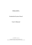
The following illustration of block diagram will show you how ROBO-678
gives you a highly integrated system solution. The most up-to-date system
architecture of ROBO-678 includes two main VLSI chips, 82815 GMCH
(Graphics and Memory Controller Hub) and 82801BA ICH2 (I/O Controller
Hub), to support Celeron/Pentium-III processor, SDRAM, 3D graphic
display, PCI bus interface, APM, ACPI compliant power management, USB
port, SMBus communication, and Ultra DMA/33/66/100 IDE Master. The
on-board super I/O chip, W83627HF, will support PS/2 Keyboard/Mouse,
two UARTs, FDC, Hardware Monitor, Parallel, Watch Dog Timer and
Infrared interface. Besides, two on-board LAN devices will give user more
flexibility and reliability of application in a highly-integrated environment.
The CPU socket adopts the Socket-370 type to support high availability and
reliability, and easy operation in general industry application.
The 82815 Hub provides an integration of memory controller and graphics
capability (AGP). This delivers AGP class graphics performance to PCs at
reduced cost. It dynamically allocates and de-allocates system memory for
complex 3D textures, preserving the benefits of standard AGP add-in
solutions. Its 64-bit AGTL+ based host bus interface, optimized 64-bit DRAM
interface supports two 3.3V DIMMs at the maximum bus frequency of
100/133 MHz. The 32-bit PCI bus interface supports 4 PCI masters for
external backplane support.
The 82801BA Hub employs the Accelerated Controller Hub architecture
which makes a direct connection from the graphics and memory to IDE
controllers. It supports 2-channel dedicated Ultra DMA-33/66/100 IDE
master interfaces, full Plug-and-Play compatibility, APIC (Advanced
Programmable Interrupt Controller) interface, and internal real-time clock
(RTC) to maintain time and date of a system. It also supports 2-port USB
(Universal Serial Bus feature) and PCI 2.1 Compliance operation. It fully
supports Operating System Directed Power Management via the Advanced
Configuration and Power Interface (ACPI) specification. In addition, it is also
linked via Firmware Hub Link bus to 82802AB Firmware Hub to support
BIOS read/write access. Through the PCI bus, PC87200 PCI-to-ISA bridge is
built in as a highly integrated PCI-to-ISA bridge solution for the best
industry application.
The Super I/O chip W83627HF integrates two high-speed serial ports, one
parallel port, SIR interface, Watch Dog Timer (WDT) which is enabled by
jumper setting and triggered by software, H/W monitoring, FDD interface
and 8042 keyboard controller with PS/2 mouse ports. This parallel port
supports one PC-compatible printer port (SPP, bi-direction), Enhanced
Parallel Port (EPP) and Extended Capabilities Port (ECP).
The PCI-to-ISA bridge supports a standard 16-bit ISA bus interface which is
applied for all slower I/O operations. In ROBO-678, it supports DiskOnChip
(DOC) for M-systems Flash disk, and ISA buffer driving for special I/O
applications and multi-ISA slots.
Besides, an advanced feature is used on ROBO-678 to support detecting and
monitoring of system temperature, operating voltage and fan status.
The 82802 Firmware Hub stores system BIOS and video BIOS, eliminating a
redundant, nonvolatile memory component.
There are two on-board PCI Fast Ethernet via RJ-45 Ports to support full
functionality of ROBO-678 AIO SBC (All-In-One Single Board Computer).
The on-board 68-pin PCI connector supports additional daughter board for
further support.
The graphic device is the 815E built-in Graphics Controller to support high
end of graphics accelerator. It is implemented by high performance
SDRAM 4MB to support color depths and high resolution up to 1600 x 1200
with 256 colors.
All of details of operating relations are shown in Figure 1-1 ROBO-678
System Block Diagram.
).+$/'
-
*,
!
"#$
)+&
,*
!"#
$!%&'!(
!"#$$
)**+
Hardware Configuration Setting
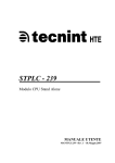
This chapter gives the definitions and shows the positions of jumpers, headers and
connectors. All of the configuration jumpers on ROBO-678 are in the proper
position. The default settings shipped from factory are marked with a star ( ! ).
2-1 Jumpers
In general, jumpers on the single board computer are used to select options for
certain features. Some of the jumpers are designed to be user-configurable, allowing
for system enhancement. The others are for testing purpose only and should not be
altered. To select any option, cover the jumper cap over (Short) or remove (NC) it
from the jumper pins according to the following instructions. Here NC stands for
“Not Connected”. (Figure 2-1)
Figure 2-1 ROBO-678 Jumper Locations
Disk-On-Chip Jumper Setting (JP5)
Memory Address Space
D8000 – D9FFF
DA000 - DBFFF
DC000 - DDFFF
DE000 - DFFFF
RTC CMOS Clear Jumper Setting (JP1)
JP1
1-2
2-3
Function
Normal Operation !
Clear CMOS Contents
AT/ATX Power Selection (JP3)
JP3
Function
3-5, 4-6 Select ATX Power Supply
1-3, 2-4 Select AT Power Supply
!
On-board Ethernet1 (82559) enable/disable (JP6)
JP6
1-2
2-3
JP5
1-2 !
3-4
5-6
7-8
Function
On-board Ethernet1 Enabled !
On-board Ethernet1 Disabled
On-board Ethernet2-PHY (82562ET) enable/disable (JP4)
JP4
1-2
2-3
Function
On-board Ethernet2-PHY Enabled!
On-board Ethernet2-PHY Disabled
Safe Mode Jumper (JP2)
JP2
Short Enabled
NC Disabled
Function
!
Watch Dog Timer Setting Jumper (JP7)
JP7
Short Enabled
NC Disabled
Function
!
2-2 Connectors
I/O peripheral devices and Flash disk are connected to the interface connectors and
DOC socket located on this single board computer (Figure 2-2).
Figure 2-2 ROBO-678 Connector Locations
CONNECTOR
J1
J2
J3
J4
J5
J6
J7
J8
J9
J10
J11
J12
J13
J14
FUNCTION
IDE1 (Primary) interface
Floppy connector
IDE2 (Secondary) interface
Parallel port connector
COM1 serial port
COM2 serial port
IrDA (infrared) port
System reset
External speaker interface
Keyboard lock and power indicator
IDE1/IDE2 active status report
On-board Ethernet ( Intel 82801BA )
interface connector
ATX power button interface
Chassis FAN power connector
REMARK
2 x 5 shrouded header
2 x 5 shrouded header
Reserve 6-pin for SIR
LED indicator
RJ-45
Connect to Chassis
Connect to Chassis
CONNECTOR
J15
J16
J17
J18
J19
J20
J21
J22
J23
U15
U25
DIMM1 – 2
FUNCTION
ATX power control interface
On-board Ethernet ( Intel 82559 )
interface connector
CPU FAN power connector
Two-port USB interface
68 pin PCI Connector
On-board VGA connector
External keyboard interface
Standard 5-1/4” disk drive power
connector
PS/2 keyboard/mouse connector
Socket 370
M-systems Flash Disk
DIMM socket
REMARK
Connect to Backplane
RJ-45
2 x 5 shrouded header
Connect to backplane
4-pin connector
(pitch : 0.2 inch)
6-pin Mini-DIN
Celeron/PIII CPU
DIP 32-pin socket
3.3V SDRAM
Pin Assignments of Connectors
J8: Reset Header
PIN No
1
2
Signal Description
Reset
Ground
J9 : External Speaker Header
PIN No.
1
2
3
4
J10 : Keyboard Lock Header
PIN No.
1
2
3
4
5
Signal Description
Speaker signal
N/C
Ground
+5V
Signal Description
+5V (220 ohm pull-up for power LED)
N/C
Ground
Keyboard inhibit
Ground
J11: IDE1/IDE2 Active LED Header
PIN No.
1
2
Signal Description
+5V (470 ohm pull-up for HDD LED)
HDD Active # (LED cathode terminal)
J5/J6 : Serial Port-1/Port-2 Connector (2 x 5 shrouded header)
PIN No.
Signal Description
1
Data Carrier Detect (DCD)
2
Receive Data (RXD)
3
Transmit Data (TXD)
4
Data Terminal Ready (DTR)
5
Ground (GND)
6
Data Set Ready (DSR)
7
Request to Send (RTS)
8
Clear to Send (CTS)
9
Ring Indicator (RI)
10
N/C
J22 : Standard 5-1/4” disk power connector
PIN No.
1
2
3
4
Signal Description
+12V
GND
GND
+5V
J13 : ATX Power Button Interface
PIN No.
1
2
Signal Description
Pull-high 100 ohm to +5V
Power Button Control Signal
J15 : ATX Power Control Connector
PIN No.
1
2
3
4
Signal Description
ATX Power Good Signal
ATX 5V Stand-by
ATX Power On Control
Ground
J23 : PS/2 Keyboard/Mouse Connector (6-pin Mini-DIN)
PIN No.
1
2
3
4
5
6
Signal Description
Mouse Data
Keyboard Data
GND
+5V
Mouse Clock
Keyboard Clock
J7 : Standard IrDA Header
PIN No.
1
2
3
4
5
6
Signal Description
VCC (+5V)
IOVSB
IRRX
Ground
IRTX
OVCROFF (Over Current Off)
J18 : Two-port USB Interface Connector
PIN No. Signal Description
PIN No.
1
+5V
2
3
USBD0+
4
5
+5V
6
7
USBD1+
8
Signal Description
USBD0USBGND0
USBD1USBGND1
J21 : External Keyboard Connector
PIN No.
Signal Description
1
Keyboard Clock
2
Keyboard Data
3
N/C
4
Ground
5
+5V
J14/J17 : Chassis/CPU Fan Power Connector
PIN No.
1
2
3
Signal Description
Ground
+12V
Pull-up 5V (Reserved for sense signal)
J12/J16 : Ethernet RJ-45 Interface Connector
PIN No.
1
2
3
4
5
6
7
8
Signal Description
TX+
TXRX+
Termination to Ground
Termination to Ground
RXTermination to Ground
Termination to Ground
J20 : On-board VGA Connector (2 x 5 Shrouded Header)
PIN No.
1
2
3
4
5
6
7
8
9
10
Signal Description
J1 /J3: IDE1/IDE2 Interface Connector
PIN No. Signal Description
PIN No.
1
RESET#
2
3
Data 7
4
5
Data 6
6
7
Data 5
8
9
Data 4
10
11
Data 3
12
13
Data 2
14
15
Data 1
16
17
Data 0
18
19
Ground
20
21
DMA REQ
22
23
IOW#
24
25
IOR#
26
27
IOCHRDY
28
29
DMA ACK#
30
31
INT REQ
32
33
SA1
34
35
SA0
36
37
HDC CS0#
38
39
HDD Active#
40
Signal Description
Ground
Data 8
Data 9
Data 10
Data 11
Data 12
Data 13
Data 14
Data 15
N/C
Ground
Ground
Ground
Pull-down
Ground
N/C
CBLID#
SA2
HDC CS1#
Ground
J4: Parallel Port Connector
PIN No. Signal Description
1
Strobe#
2
Data 0
3
Data 1
4
Data 2
5
Data 3
6
Data 4
7
Data 5
8
Data 6
9
Data 7
10
Acknowledge#
11
Busy
12
Paper Empty
13
Printer Select
PIN No.
14
15
16
17
18
19
20
21
22
23
24
25
26
Signal Description
Auto Form Feed#
Error#
Initialization#
Printer Select IN#
Ground
Ground
Ground
Ground
Ground
Ground
Ground
Ground
N/C
J2 : FDC Interface Connector
PIN No. Signal Description
1
Ground
3
Ground
5
Ground
7
Ground
9
Ground
11
Ground
13
Ground
15
Ground
17
Ground
19
Ground
21
Ground
23
Ground
25
Ground
27
Ground
29
Ground
31
Ground
33
Ground
PIN No.
2
4
6
8
10
12
14
16
18
20
22
24
26
28
30
32
34
Signal Description
Density Select 0
N/C
Density Select 1
Index#
Motor ENA#
Drive Select B#
Drive Select A#
Motor ENB#
Direction#
Step#
Write Data#
Write Gate#
Track 0#
Write Protect#
Read Data#
Head Select#
Disk Change#
J19 : 68 pin PCI Connector
PIN No.
Signal Description
1
VCC
3
AD1
5
AD3
7
AD5
9
AD7
11
VCC
13
AD9
15
AD11
17
AD13
19
AD15
21
VCC
23
AD17
25
AD19
27
AD21
29
AD23
31
VCC
33
AD25
35
AD27
37
AD29
39
AD31
41
VCC
43
BE#1
45
BE#3
47
Frame#
49
IRDY#
51
VCC
53
Devsel#
55
SERR#
57
GNT#4
59
Reserved for GNT#3
61
PCI Clock1
63
PCIRST#
65
IRQ#A
67
IRQ#C
PIN No.
2
4
6
8
10
12
14
16
18
20
22
24
26
28
30
32
34
36
38
40
42
44
46
48
50
52
54
56
58
60
62
64
66
68
Signal Description
AD0
AD2
AD4
AD6
GND
AD8
AD10
AD12
AD14
GND
AD16
AD18
AD20
AD22
GND
AD24
AD26
AD28
AD30
GND
BE#0
BE#2
PAR
TRDY#
GND
STOP#
Reserved for PERR#
REQ#4
Reserved for REQ#3
GND
PCI Clock2
LOCK#
IRQ#B
IRQ#D
!
System Installation
This chapter provides you with instructions to set up your system. The
additional information is enclosed to help you install M-systems Flash disk, set
up onboard PCI device and handle WDT operation in software programming
3-1 Socket 370 Celeron/PentiumCeleron/Pentium-III Processor
Installing S370 CPU
1) Lift the handling lever of CPU socket outwards and upwards to the other end.
2) Align the processor pins with pin holes on the socket. Make sure that the
notched corner or dot mark (pin 1) of the CPU corresponds to the socket’s
bevel end. Then press the CPU gently until it fits into place. If this operation
is not easy or smooth, don’t do it forcibly. You need to check and rebuild the
CPU pin uniformly.
3) Push down the lever to lock processor chip into the socket.
4) Follow the installation guide of cooling fan or heat sink to mount it on CPU
surface and lock it on the socket 370.
Removing CPU
1) Unlock the cooling fan first.
2) Lift the lever of CPU socket outwards and upwards to the other end.
3) Carefully lift up the existing CPU to remove it from the socket.
Follow the steps of installing a CPU to change to another one or place
handling bar to close the opened socket.
Configuring System Bus
ROBO-678 will automatically detect system bus based on the CPU used.
However, users may configure CPU core/bus ratio in BIOS setup menu for
engineering sample processor.
3-2 Main Memory
ROBO-678 provides two DIMMs (168-pin Dual In-line Memory Module) to
support 3.3V SDRAM (Synchronized DRAM) as on-board main memory. The
maximum memory size is 512MB. ROBO-678 will automatically detect
memory clock, based on the processor and SDRAM used. Please refer to the
following table as your reference.
ROBO-678 Memory Clock Reference Table
Processor FSB PC-100SDRAM PC-133SDRAM
133MHz
100MHz
133MHz
100MHz
100MHz
100MHz
66MHz
100MHz
100MHz
For system compatibility and stability, don’t use memory module without brand.
You can also use the single or double-side DIMM with ECC feature(2).
Randomly installing DIMM in any DIMM socket is allowed. You can install
different size of DRAM module on DIMM1, DIMM2 or all to boot up system.
Watch out the contact and lock integrity of memory module with socket, it will
impact on the system reliability. Follow normal procedure to install your DRAM
module into memory socket. Before locking, make sure that the module has
been fully inserted into the card slot.
NOTE :
(1) To maintain system stability, don’t change any of DRAM parameters in
BIOS setup to upgrade your system performance without acquiring
technical information.
Due to Intel 82815 chipset limitation, SDRAM with ECC function is not
supported. In the event of ECC SDRAM being adopted, ECC function is
NOT supported while it is still OK to use this type of SDRAM.
Due to Intel 82815 chipset limitation, Buffered (Registered) SDRAM is
not supported. Buffered SDRAM will simply freeze up system.
3-3 MM-systems Flash Disk
ROBO-678 reserves one 32-pin DIP sockets for installing M-systems Flash disk
from 2MB to 288MB. This operation structure is running with pure ISA-bus
without PnP (Plug and Play) function. Before installing, make sure that I/O
address jumper setting is set on right position to prevent unworkable system
due to I/O resource conflict. Do remember to follow DOC (DiskOnChip)
installation procedure. Otherwise, it is possible to burn out the Flash chip due to
incorrect installation.
Installing DOC
Align the DOC with pin holes on the socket. Make sure that the notched corner
or dot mark (pin 1) of DOC corresponds to notched corner of the socket. Then
press the DOC gently until it fits into place. If installation procedure is correct,
the Flash disk can be viewed as a normal hard disk to access read/write data.
WARNING
Please ensure that your DOC is properly inserted. Placing the DOC in
reverse will cause severe damage. Remember, a new DOC chip is always
a formatted disk. You may simply plug the chip on the DOC socket and
read/write through it. If you would like to boot from this Flash disk, it is
necessary to refer to the application note from M-systems. You can easily
get relative information from M-systems shipping package (such as
product manual) or Web-site
http://www.m-sys.com.
3-4 Installing the Single Board Computer
To install your ROBO-678 into standard chassis or proprietary environment,
you need to perform the following :
Step 1 : Check all jumpers setting on proper position
Step 2 : Install and configure CPU and memory module on right position
Step 3 : Place ROBO-678 into the dedicated position in your system
Step 4 : Attach cables to existing peripheral devices and secure it
WARNING
Please ensure that your SBC is properly inserted and fixed by mechanism.
Otherwise, the system might be unstable or do not work due to bad contact of
golden finger and ISA-bus slot. It is recommended to apply 4-pin 5-1/4” IDE
device power connectors from your power supply onto J22 to ensure a
sufficient current supply.
NOTE : Please refer to section 3-4-1 to 3-4-3 to install INF/VGA/LAN drivers.
3- 4- 1
INF Chipset Component Driver
Intel 82815 GMCH chipset is a new chipset that a few old operating systems
might not be able to recognize. To overcome this compatibility issue, for
Windows Operating Systems such as Windows-95/98/98SE/2000, please install
INF Chipset Component driver before any of other Drivers are installed.
You can find very easily the INF chipset component driver in /INF directory of
ROBO-678 CD-title. Please execute “Setup.exe” to start installation.
3- 4- 2
Intel 82815 GMCH Graphics Controller
Intel 82815 GMCH chipset is the result of new design approach to optimize the
shared memory architecture while maintaining the cost benefits of integration
through Direct AGP and Dynamic Video Memory Technology.
With no additional video adaptor, this onboard video will be the system display
output. However, system will automatically switch to off-board video adaptor if
there is any. In this case, onboard 82815 GMCH graphic feature will be disabled.
Drivers Support
Please find Intel 82815 GMCH driver in /Graphics directory of ROBO-678 CDtitle. Drivers support Windows-3.1, Windows-95/98/98SE, Windows-NT
3.51/4.0, Windows-2000, OS2, and Linux.
(1) Windows-95: Please bring up the Display Control Panel and update
graphics driver with .
(2) Windows-98/98SE: Please execute to
start graphics drivers installation, or bring up the Display Control Panel and
update graphics driver with .
(3) Windows-NT 4.0: Please install Windows-NT 4.0 Service Pack 4 or above
first, then execute , or simply bring
up the Display Control Panel and update graphics driver with
.
(4) Windows-2000: Please bring up the Device Manager and update graphics
drivers with !
"""#.
(5) Redhat Linux V6.2: Please refer to the “release_linux.pdf” readme file in
$ directory for graphics drivers installation guide.
3- 4- 3
Intel 82559 / 82801BA MAC Fast Ethernet
Controller
The following table indicates how to enable/disable on-board Intel 82559 /
82801BA MAC Fast Ethernet function by putting jumpers at proper position.
JP6
1-2
2-3
FUNCTION
Enable On-board Intel 82559 Ethernet
Disable On-board Intel 82559 Ethernet
JP4
1-2
2-3
FUNCTION
Enable On-board Intel 82562ET PHY
Disable On-board Intel 82562ET PHY
Drivers Support
Please find 82559 LAN driver in /Ethernet directory of ROBO-678 CD-title. The
drivers support Windows-NT 3.51/4.0, Windows-95/98/98SE, Windows-2000,
Windows-2000, SCO OpenServer 5.0.2, SCO Unixware 7.0, OS2 and Linux.
In Windows environment, Intel 82559 Fast Ethernet should appear as %&'
(&)""*+
,-.
, and Intel 82801BA MAC Fast Ethernet should
appear as %&'(&)""/0!1.
On-board LED Indicator (for LAN status)
ROBO-678 provides six LED indicators to report Intel 82559 / 82801BA MAC
Fast Ethernet interfaces status. Please refer to the table below as a quick
reference guide.
Intel
Intel
82801BA 82559
MAC
Name of LED
Operation of Ethernet Port
ON
Off
D16
D20
LAN Link Integrity LED
D17
D22
LAN active LED
Active
No active
D18
D23
LAN speed LED
100 Mbps
10 Mbps
3- 4- 4
Good link in 10 or 100 Mbps Bad link
OnOn-board 6868-pin PCI connector
ROBO-678 provides one on-board 68-pin PCI connector that allows you to apply
additional PCI devices, such as SCSI or Ethernet. If you have a compatible PCI
device, simply plug it onto the connector and secure it with two retention bars.
3 -5
Clear CMOS Operation
The following table indicates how to enable/disable CMOS Clear Function
hardware circuit by putting jumpers at proper position.
JP1
1-2
2-3
FUNCTION
Normal Operation
Clear CMOS Contents
To correct operate CMOS Clear function, users may turn off the system, move
JP1 jumper to 2-3 position (this will not consume any power). To clear CMOS,
please turn on the power and turn it off again for AT system, or press the toggle
switch a few times for ATX system. Move the JP1 back to 1-2 position (Normal
Operation) and start the system. System will then produce a “CMOS Check Sum
Error” message and hold up. Users may then follow the displayed message to
load in BIOS default setting.
3 -6
Watch
Watc
h Dog Timer Programming
!
"!#$ #!#!#!#
JP7
FUNCTION
Short Enabled
NC Disabled
#!#!!!!!! $ #!%!!&
There is one programming guide (source code in Assembly language) and test
program in ROBO-678 CD-title. Please refer to the programming guide to create
your own Watch Dog Timer application, and feel the Timer by using the demo
program.
!"#
#$%!
&
%
#&$"
% %$$#
'
"
$$ %
# ( &##&
)&
&&* &
"
&$"
$# ' ##% $ % &( '
#
!%$("
&"##
+ ,-"##
"$&"!
!&##
"./0+12$%
+ ,-3
(
02*%##%
"#
$#
"
!$ % ( ! % (
%
#%.'1 3"!%"
4(&5++ 5!6#%
$#. 3
!%
"0'2(02(02*%
#
%$%
*%
"#
%
#!(#
"!
%%"!
*(
-
072+ ,-
#
/1+8
(%&
*%!&
#"
#$%
%
##
#&
%
%
# !
!
%$*%
*$&
ROBO-678 User’s Manual
!
!
$!
%!
#!
*+!
*-!
*.!
*0!
*+2!
"#
#
!
#
#
#
!
#
"#
#
!
#
#
#
!
#
%%&
#
'()
) )
( )
%%#
,
)
!
'()
%
/"()
1
)
'()#
&%',%(%
% & $# ) $&
9&&
,
*%
&#"#
0+2*%&&!"
!#
',%'%":';7<=>???
)'()*
*
5
#36
'
#
/"()*
*%)
#
'
*
(1
"
)
)
)
)
3 '"'
)
7)
'4
)
#9& *+29)
7)
8)
↑↓←→9)
#"
:
;
;4!:
<=
!"
ROBO-678 User’s Manual
"&
#
&#!,
*%
""#
0-",2@0-"20A2@02*%
&)#!%&#
0+2*%&$%
&##*%
'!&"#((#
(
!$%
!"
)'()*
Date:
Time:
Mon, Oct 2 1999
16:51:13
Item Help
____________________________
#"
#"
#"
#"
IDE
IDE
IDE
IDE
Primary Master
Primary Slave
Secondary Master
Secondary Slave
Press Enter None
None
None
None
Drive A
Drive B
1.44M, 3.5 in.
None
Video
Halt On
EGA/VGA
All, But Keyboard
Based Memory
Extended Memory
Total Memory
Menu Level
#
Change the day, month,
year and century
640K
260096K
261120K
↑↓←→
9)
#$3%3 3 96
*+29)
)'9*+9,
4
*-9 6
*.9*%)
*09(1
!" :
" 99
499
(
#
A=A:
" )
(
#
A=A:
")
#
(
#
A=A:
")
#)
(
#
A=A:
ROBO-678 User’s Manual
#
)
= >
?@
##
)
B
C B
C B
C B
C /
/
>
D.2E;-=F-
+=F;-=F-
0F2E;D=-
+=AA;D=-
F=GG;D=-
,36,
',A2
',G2
(>(
>
;E
;!
;!3E
>3
>3
:
>3
6
4(
#
)
#
!
)
#
#
)
# # /"() (): #
#
#
#
+
&+)&
(
&
*)&#)
!#&$"&
*)
!"
'())
H'I+JGA%F222)
" IDE HDD Auto-Detection
Press Enter
IDE Primary Master
Access Mode
Auto
Auto
Cylinder
20491
Cylinder
Head
Precomp
Landing Zone
Sector
39703
16
0
39702
63
Menu Level
##
MB
To auto-detect the HDD’s size, head...
on this channel
↑↓←→
9)
#$3%3 3 96
*+29)
)'9*+9,
4
*-9 6
*.9*%)
*09(1
ROBO-678 User’s Manual
Item Help
____________________________________
!" "4
%
#
>
'#
!
1
#
%
#
4#
=
" # ##
; =
)
#?@
#
=)
#
!=K
:
K
#
#
;
;
#=
>
9 '( L.--D-
>(>M
!
##
=>
1
1
!
!#
#!=
'
##
!
>
/
:
#
?" @
?@
'
L2
)
#
!=
L.--D-
4
L2
)
3
LF--
#
L2
NNNN9)
.--D-
L.--D-
!
1
L2
NNNN
L.--D-
)
#
L2
>
#
#!
LF--
ROBO-678 User’s Manual
" ##
&
%&$"%
%
#$!
&6)
% & %
#B
$ ( ! &( *%!
(
"
&%
!"
'())
H'I+JGAHF222)
#
/"()*
Virus Warning
CPU Internal Cache
External Cache
CPU L2 Cache ECC Checking
Quick Power On Self Test
First Boot device
Second Boot device
Third Boot device
Fourth Boot device
Boot Up NumLock Status
Typematic Rate Setting
Disabled
Enabled
Enabled
Enabled
Enabled
HDD-0
Floppy
CDROM
ZIP100
On
Disabled
X Typematic Rate (Chars/Sec)
X Typematic Delay (Msec)
Security Option
OS Select For DRAM > 64MB
HDD S.M.A.R.T. Capability
Video BIOS Shadow
C8000-CBFFF Shadow
CC000-CFFFF Shadow
D0000-D3FFF Shadow
D4000-D7FFF Shadow
D8000-DBFFF Shadow
DC000-DFFFF Shadow
6
250
Setup
Non-OS2
Disabled
Enabled
Disabled
Disabled
Disabled
Disabled
Disabled
Disabled
Item Help
___________________________________
Menu Level
#
↑↓←→
9)
#$3%3 3 96
*+29)
)'9*+9,
4
*-9 6
*.9*%
*09(1
+!
!
&)
#&% %
# !
&
" "#
"%"#
&&
!
&
*!
4 " #
" %" #
&&
!
&
*!
ROBO-678 User’s Manual
&"
##% &&
/)( '-,@&
"
+!
!
+!&&
!&&
#
%!@
!'-,1>'&+''&&*"
&&C+!@
!
!
&"% - $ :- ; $ % &#$
+!(
*
#&&*#
"
- +!
!
+!&*- 4#- "#!#"$%
#
"
%
#$#)&
&
&
#
'&C%(17>?(D-7??(/('('(14(
!
$&'(
&
$4#1&*
&&C+!@
!
ROBO-678 User’s Manual
!)&(*
E%
*
#!%*%!&!(
%#&%#&%&!
&
&&C+!@
!
!)&(*+,
#!$#
&*%
*%*%
&&C((7?(7>(7F(>?(>=(G?
!)&(%)+-,
% # $ *% !$ !"
*%
*
&&C>F?(F??(F?(7???
)&
&
)%#
%
#!
%
%
%
#!&&
!$
&&
#
%
#!(!&&
!$
&&
#
4C !
&%(
&-+ 4H
%!
*
%%"I
0+2(
!
&%&
&%
!(
%
#
!%&$%
ROBO-678 User’s Manual
"%*.-/01-$
&"
%
#
""=$
%
#
&&C4>(>
2%%3-3.3*3!3&4)
!@
!-'&$$$
)
&&C+!(
!
#$#
&.+!3!
"JH
)G=E
%
#
##%
""
%$#&.
!3"
"$&
&&C+!@
!
#-()+ (##56667%""""890:&
(,
& .+!3 ! " $& $ & ##% "#
.
!3"
"$&
&&C+!@
!
ROBO-678 User’s Manual
!
&
%&$"
%
#!
&$&$
$
>7FH'/&
&
#"
!
&&
%
#
##% &
( & :; 9 && &
&##&
!&)!
-'!
#
!
#
)! $
"
) ! &
!&
% ) !
" &
$ %
%
# %#%#"&
#*"%&"
!$%
&)
!"
"%
%
#
!"
'())
H'I+JGAHF222)
#
'
*
SDRAM CAS Latency Time
SDRAM Cycle Time Tras/Trc
SDRAM RAS-to-CAS Delay
SDRAM RAS Precharge Time
System BIOS Cacheable
Video BIOS Cacheable
Memory Hole AT 15-16M
Delayed Transaction
Display Cache Frequency
System Memory Frequency
On-Chip Video Window Size
3
7/9
3
3
Enabled
Enabled
Disabled
Enabled
100 MHz
Auto
64MB
* Onboard Display Cache Setting *
CAS# Latency
Paging Mode Control
RAS-toCAS Override
RAS# Timing
RAS# Percentage Timing
3
Open
by CAS# LT
Fast
Fast
Item Help
____________________________
#
Menu Level
↑↓←→
9)
#$3%3 3 96
*+29)
)'9*+9,
4
*-9 6
*.9*%)
*09(1
&
"
'-, &&
%#& # &&
##%
:; $ #"
) ! &$% &
% !
$
!"
&
&#"&&$%
%
#
#9 &
" %
#% ! )"%$
##%&
ROBO-678 User’s Manual
%*.-.)!(
&
#!$'1E
!#&##
# !% # H'/ #
&
$#
'&C>(G'1E
%*.-)!(!!
&
#!$&&*
&&
&%&
'&CF@(@<
%*.-*.77.%)
&
#!$'1E
:'&*;$#&)
&## &## $ % %
# " % $
( % & .G '1E
3 ! ! ##%
$#&4#%(!
G'1E
'&C>(G'1E
%*.-*.
!(
&
#! $ '1E
$ K &" $ % %
#
"%$(%&
.G'1E
3!
!##%$#&
'&C>(G'1E
)($4
&"+!
&&"$
%
#????(
"!
%
#$#&/)($%"#
##%(
%
##%
&&C+!@
!
ROBO-678 User’s Manual
#$4
&.+!3!&&"JH1>&&""
%
$#&.
!3"
&&"$&
&&C+!@
!
-()2.9;790-
#) $#&( & & ##% ) $ &
##%#
!###%
&!7
'&C+!@
!
%)!
&.+!3!%
& &$#&$
#
!$$-'!
'&C+!@
!
%&)"<)
&$" % && $&% $
"
7??/L
'&C7??/L@7GG/L
)(-()"<)
&$"
%
###%$&% $
"
'&C7??/L(7GG/L
7&##=
%
&
L$###%$H-"&
'&C=@
!
ROBO-678 User’s Manual
.>)
&
$&##%&&*
'&C>(G'1E
-#
&
H'/##%&
)"
"
&
'&C@'
*.77.#
&
$ % && &&* &
K'K%
'&C!%'K1 @):>;
*.>!(
&
K&)&"($
K&)%
'&C
@
*.>
!(
&
K&"&##%&&*
'&C
@
ROBO-678 User’s Manual
"#
!$
!"
'())
H'I+JGAHF222)
"
On-Chip Primary PCI IDE
On-Chip Secondary PCI IDE
IDE Primary Master PIO
IDE Primary Salve PIO
IDE Secondary Master PIO
IDE Secondary Salve PIO
IDE Primary Master UDMA
IDE Primary Salve UDMA
IDE Secondary Master UDMA
IDE Secondary Salve UDMA
USB Controller
USB Keyboard Support
Init Display First
IDE HDD Block Mode
POWER ON Function
KB Power On Password
Hot Key Power On
Onboard FDC Controller
Onboard Serial Port 1
Onboard Serial Port 2
UART Mode Select
RxD , TxD Active
IR Transmission Delay
UR2 Duplex Mode
Onboard Parallel Port
Parallel Port Mode
EPP Mode Select
ECP Mode Use DMA
Restore After AC Power Loss
Enabled
Enabled
Auto
Auto
Auto
Auto
Auto
Auto
Auto
Auto
Enabled
Disabled
PCI Slot
Enabled
BUTTON ONLY
Enter
Ctrl-F1
Enabled
3F8/IRQ4
2F8/IRQ3
Normal
Hi,Lo
Enabled
Half
378/IRQ7
SPP
EPP1.7
3
off
Item Help
Menu Level
#
↑↓←→
9)
#$3%3 3 96
*+29)
)'9*+9,
4
*-9 6
*.9*%)
*09(1
&()#)%
&
&
-'+$&
$+&
&
+!&)#%+$&&
!&)
$&
&&C+!@
!
ROBO-678 User’s Manual
%()#)-
$+-:-"##@;$
%
-#:?=;
$&$$+)&
!+$&
?
"=)
&&
)%&
$#&#(
%
#
#&%#
!
#$&)&
&&C(?(7(>(G(=
%()#)-%-.
, @GG@@7?? ## ! % $ % + )
" )# &
) :
<F
>%+!
#
);$%)%
%
#
$!
,@GG@@7??(
&!
'&C(
!
$
#
%!@
!,:,)
;$&
&&C+!@
!
$:)4#&&
#
%!,*%!$&- (
#((
4 ,)
&&C+!@
!
%&)"
#
%
&$
%!L
&&C-':$$!);(!@H-
ROBO-678 User’s Manual
%2%%$-#
#
%!@
!+/&* $&
&& !% !" ) # %
#
!$$$$ & ! $
#
&
%
#$#&
&&C+!@
!
"
#
%
&$$
&#
" 8
%
!
&'(
%
)
*
+
,
-!%
-!%*%!<
-
"&
#L
"
-
"
&&
#L*%
-
"#
$&&*
-
"#
"&&*
-
"%*%!*%
:)4##
)$.-&3!"&$"
.-
3(
#
! ! $ " -
.+3 *% &
#L ( &$#"!"
*&
&$#
#&&$"(#
"$.-
!M-
%*%
&N3!#
2:)
)$.-&3!"&$"
./E%3(
#
!!$"
&&C'7'7>
ROBO-678 User’s Manual
4#"%
#
%!@
!!%
*&
&&C+!@
!
4#9
&
&
"$$
&
&&CG@O=(>+@OG(G+@O=(>@OG(
!(
.*!-#
#
&$
#
#
#,
,+
!$$&
&#
#
&E#
#
$
#
$&
!
>('>
!
!
*%8!%.
#
&$"$
#
)!C
)-)
)-*
*-)
*-*
/"$&)"@/"$
#"
/"$&)"@1$
#"
1$&)"@/"$
#"
1$&)"@1$
#"
4#
#
%&$"@
$!
'&
C
!(G@O(>@OF(G'@O
ROBO-678 User’s Manual
-#
$$$#
$!C
%%
%%
%
%.%%
&--#
&+--#
&+'-#
&+'-A+--#
-#
&$$)
$+--#
&&
C+--7@+--7<
-#%-.
&&$+'-#
&&
CG@7
*. .
#
&$"
$
" 8
%
$
&&
%
##&%
!&*
%
#
%
M$$
%
#
!&*)
:$$;
/
ROBO-678 User’s Manual
%#&'
- "# % &$" % %
# #
$$&)%
)"%"#&
%
%
$&#
!"
'())
H'I+JGAHF222)
)
ACPI function
Enabled
ACPI Suspend Type
S1(POS)
Power Management
User Define
Video Off Method
DPMS
Video Off In Suspend
Yes
Suspend Type
Stop Grant
Suspend Mode
Disabled
HDD Power Down
Disabled
Soft-Off by PWR-BTTN
Instant-Off
Resume On Ring
Enabled
CPU THRM-Throttling
50.0%
Resume by Alarm
Disabled
Date(of Month) Alarm
0
Time(hh:mm:ss) Alarm
0 0 0
** Reload Global Timer Events **
Primary IDE 0
Disabled
Primary IDE 1
Disabled
Secondary IDE 0
Disabled
Secondary IDE 1
Disabled
FDD,COM,LPT Port
Disabled
Item Help
_____________________________
#
Menu Level
↑↓←→
9)
#$3%3 3 96
*+29)
)'9*+9,
4
*-9 6
*.9*%)
*09(1
."
# % !@
! )& '$" -
"#:'-;
&&
C+!@
!
-
(
&"% % & % : "; $ )" &%./-3(.
3
&
$-"#($&)$9#
"
ROBO-678 User’s Manual
## #"# P 7 (
/-P7F#
0"%
9###"#
P7#(
/-P7#
% & # )% 1#
!(
"
$#7#7
/-"
$#7#7F#
"%
# -#
#
#&#
!*
$2)3.!4
!4
#% &&
%
#$$)&
L %&L !*
)!$$
%
!*
)!$$
%#"#
""
# &#
!@
!)$$
&&
C6
@4
&#!)&
)!CH-
&#-#
!$
#$
%
#&)%()&
9&
'-,!
$$
2%%%
!$
#$
%
#&)%(
*)!
)&
#&)
ROBO-678 User’s Manual
7 4)*7$!!'
#
##)$!
&&
C
$$@%=&
*(*
& .+!3( %
# $$$ # ! *1*#
"
&&
C+!@
!
!(7!
# % &$" '-, *" % &%& " #
&&
C7>FQ(>F?Q(GFQ(F??Q(>FQ(F?Q(FQ
*(4).(
# !@
! # !% # $& .+!3
&(
%
#
" 8
%&!$
&
#L#%
&
%+ -,.(
.
#!%#3
!(
#&
&$"
#$#"&
%
#
&&
C?RG7
!(+?((?,.(
.
#!%#3
!(
#&
&$"
##$#"&
%
#
&&
C:?R>G;(##:?RF<;(
:?RF<;
ROBO-678 User’s Manual
()#)%69
# &$" + )&
!" # !% %
# *
%
#$
#$
&)&
!
%
&&
C+!@
!
"%%8-8!
# &$" $% )&( ' ( !"
#!%
%
#
*
%
#$
#$
&
)&
!
%
&&
C+!@
!
ROBO-678 User’s Manual
(##)#*
&
&!
&$""-'!
%
#-'(
#
&&(
%
#&
@)&
"
'-,
$
&##&"
&&#
&&)
#)%&&#
"%&##
%9&
#*%&"
$
"
!"
'())
H'I+JGA%F222)
3 '"'
Reset Configuration Data
Resources Controlled By
#" IRQ Resources
#" DMA Resources
PCI/VGA Palette Snoop
Disabled
Auto(ESCD)
Press Enter
Press Enter
Disabled
Item Help
------------------------#
Menu Level
BIOS can automatically
configure all the
boot and Plug and Play
compatible devices.
If you choose Auto,
you cannot select IRQ
DMA and memory base
address fields, since
BIOS automatically
assigns them
↑↓←→
9)
#$3%3 3 96
*+29)
)'9*+9,
4
*-9 6
*.9*%)
*09(1
* %
4#%(%)
$
!&+!
+9%
#
'$":+';%9$%)
& %
# &$" &
& &$& "
%
#&!
&&C+!(
!
ROBO-678 User’s Manual
*#4)
-"-%
&&%#&%&$"$
!-"-%&#!)&
/)(
&!%#
!
%"
%
"-"-%"
%
#
&
<F$%
$.#3&
&$&
&
!%""
&$
!#$
$:
!#
&!%.#3;
&&C:+';(
**
&
& #%( " & %
# %(
"%$)&
"
%#
O
"!
)!%-'
1"&%$
)&
&# " -' !
&$&( -'@ -- $
)&
&#-"-%
"$-'
!
&&
'&C1"&%3.-'@--3
%-.*
&
&#%(
"&
%
#&%(
"%$)&
"&1"&%$)&
&# " -' !
&$&( -'@ -- $ )&
&#-"-%
"$-'!
&&
'&C1"&%3.-'@--3
@.&
1)
$
!
&&
C+!@
!
ROBO-678 User’s Manual
+#,$!
!"
'())
H'I+JGA%F222)
*
5
#36
'
Current System Temperature
Current CPU Temperature
System Fan(J14)Speed
CPU Fan(J17)Speed
Vcore
Vcc1.8
Vcc3.3
+ 5 V
+12 V
-12 V
- 5 V
VBAT(V)
5VSB(V)
0
5314
1.63
1.85
3.31
4.94
11.97
12.36
5.04
3.15
4.87
RPM
RPM
V
V
V
V
V
V
V
V
V
Item Help
----------------------#
Menu Level
↑↓←→
9)
#$3%3 3 96
*+29)
)'9*+9,
4
*-9 6
*.9*%)
*09(1
ROBO-678 User’s Manual
38/100
43/109
-.)/$$
!"
'())
H'I+JGA%F222)
*
5
#36
'
Auto Detect DIMM CLK
System Spectrum
CPU HOST/PCI Clock/PC133
CPU Clock Ratio
Enabled
Disabled
Default
x 5
Item Help
----------------------#
Menu Level
↑↓←→
9)
#$3%3 3 96
*+29)
)'9*+9,
4
*-9 6
*.9*%)
*09(1
.%%--:
#
%!@
!&'&*
&&
C+!(
!
&#&(
#
%!@
!
&##
&&
C+!(
!
2!9AA
#
%
&'-,/
&
"-''&*&
'-, /
-'7GG ! #&% &( $$ &#!
$
'-,&$$!-
$$"
!
&*$&"
$&
($
)$'-,/
!#&%&
/L(7??/L7GG/L
-''&*$
%
GG/L,
'-,/
-' '&* $# $ @7??/L( 7??@GG/L 7GG@GG/L( G@=>/L(77F@G/L7@=>/L,
-'7GG7GG/L
&
##(-'7GG%
!.43
&%-'7GG
7GG/L&
!!
7GG/L##%&&*
%&54&"
ROBO-678 User’s Manual
%1)2%42%677
88 )9%
--H'
'-H'
6:: )9%
-FF?+R-F?+
677 )9%
-+R-<GG+
4-'7GG
-'7GG
!
"#$"%
&##%""'
S%+""#-&
!&$"$$
%
#&&*
*
#
%
&'-,&@!
&&
CGR
ROBO-678 User’s Manual
*$
&" .$
3 $# # # % & &!!
*/#
% 0+2 # % " &$# " !9 #
"
#C
1$$
:6@4;T4
-
" U6B $ )
$ #
!(
##$#&
%
#
*9#
% 0+2 # % " &$# " !9 #
"
#C
1#L$
:6@4;T4
-
" U6B $ )
$&% "
$ #
$#&
%
#
)0#&
6&
)
(!$ $$&
!C
&&"
$
#
CI
&%!)"&"
$ #
% & $&( $" #
" &$
&
%&"
'!*.*%
% ( " &&
"( 0+2 % & % )
% $# '
##%6!
*&$#
%
"
0+26#%
0+
&2!
&
ROBO-678 User’s Manual
! ( I
0+2 % # #
" &$# ! ! & !(
%
#!%&$%
.*%%.$%
!!(%!#)%#%
% )
L
$#&""%$
%
%
#&$"
%(
!(%&
)%#%
%
#
! )L
$%&#
6 # &% :
& G; $ &% .%
#3(
!!!%$
.3(#"%&&
%"
1
$
B&
-
"0+2
#
*
$&$#C
;<32=>6
-
".63
&
##
'M
&
&
$##%
%
$%%
%
#$$ 9#%!%
&#( &$"
% %
# &&" &
'$
)")
%
#
"
-
"0+2
#
*
$&$#C
?
<32=>6
%9
"'%&" )
&
#$$& 9
%
%&#
ROBO-678 User’s Manual
#2
"-$ :- ;($&
"%
#"$9(
!&
%#
"$
#
"
%(!&&#!%C
-+7 '4 4,+(' 11 +'+1 +4 ++ ,-
'%*
$!&
&&
)
&&&L)
&
%
%$# !&&
$
""!$
!%
!
&&
%
&&
!&&
$
""!%
#$$"#
"
#%!
%$&
"- &
#
"
$!+
!,+3),,*#
'()
#="
#
=
)1 +++
'
#!'()#
#=:##
'()
#
#=:
#
!
='
#!
#
#
=
#!,*1+-+3 #,#%++
>
#
=:#
#
#
="
!
9
B
C="
; !
#
#
##
#
=
!
#
=
:
=
##+$+3% ,)+++/+11%
ROBO-678 User’s Manual
:
!
'()
=)
#
#
#=
#%*,3@)++*3
#
#
#
#=:#
#
#
)
=
#
#
#;
#
O
; )
#
6"(
#=
#%*,33%),),A#*,!
)#
;
#
=P#
=
,4%*,+1,
A1+,1*3
:
")%
#
#!#
###
#
")=:#
#
")%
#
#
#
#
#=
#
=
,
%*,+1,A1+,1*3
:
#
")%
#
=
>
98
;
")
;#
")'=
+++1+#,*BA),+##+$
4 # 1
= /
#
# #
#
##
=
#
#
#
)
=
+++,*BA),+##+**+
'1
#
=!
##
#
=/
#
#
#
)
=#
#!
O
#
#
=
*%%3#+*++++++*+%+
'1
#
=!
#
#
#
="
;
!
#)
>(>=
ROBO-678 User’s Manual
,
%*,+1,A1+,1*3
:
%
#")#
#
#
#
#=
%")##
#
=
>(:98
;
")
;#
")'=
3!,+#++++3!,+#%+
'1
!
=!
!
#
#
#!
=
"
#
!
;
#)
4:(>;/:EP/(=:#
/"()
!
#
=
,"""
"#
###=P#
#
#
#=
"""
"#
###=P#
#
#
#=
+3B),),A#*,!
#
="")
'
#
#="")
)
1
=
$"""
"#
=
#
Q
#
#=
#A,##+1#
:
#O#
"3('4>>'4'E ":P(
#
#
=
#AA :
#O#
"3('4>>'4'E ":P(
#
=
ROBO-678 User’s Manual
%+,3+!
:
#
##
5
= !
=
%+6#,!* -C+!
8
/"()
#>%!
"
#;
>"#
;#
>"
=
+, %,+3+++/)A+A """
"#
##
=
!!,!
%*,+1,A1+,1*3
"#
"=
>(:R8
;
")
;#
")'=
)
,!!
%*,+1,A1+,1*3
:
" 5
; " #
=
>(:9 8
;
")
;#
")'=
"#
") ' # # =
>(:98
;
")
;#
")'=
3 ),*#-<+*/,*/#*=+!"""
"#
= '::!
=
@!
%*,+1,A1+,1*3
ROBO-678 User’s Manual
:
"
#
"
")%
=
>(:98
;
")
;#
")'=
*%%3#<=<(:=→
→1&&"
*%%3#<=<D:=→
→"
)#4<=<(:=→
→)##
)#4<=<D:=→
→)##"
)#4<=<C:=→
→)##9"
)#4<=<6:=→
→1&&04"
)#4<=<:(=→
→$"
&4/144"
&4&"
'1
!
=!
!
#
#
#!
=
!+ 4/"
:
#
#!(
*22224%*****4=
"
/"()
=
ROBO-678 User’s Manual
#2!3#
4
)
-$ :- ;
&- - '-,
"
&
- &&* &
&&
! ) $&" -:@?;
) &)! &&
" - ( %
# % #
" &!" #
" 9" !# !#&!&&
"- (
"
&&*!%
"&@
?/ &&!
!
$
9&"
&
&%!"$# !
$%
%
#!
$&
#&(- &
#
%&&*&?/$
%
#"
!$&
#()?/!
$#
&
(#&!
%
&
$"- &&*&
)$ &
&$?@7F@<F)
>:+&;
#
'*
'2
'+
'D
'-
2+
2F
2D
2A
2-
2.
20
:
'()38#=
#
19
%
%
F##
#!
0
% ##
#
%%
#1
;
''=
%%
#F##
#!
0
#
/"()#
'#
!#/"()#!2227*222
=
S#
##
+22292
")
TT"#=
+=/!#
F='
'()
+='
G2AF
#
F="1
G2AF
%
ROBO-678 User’s Manual
2G
2J
2
2/
2'
2
2
2*
+2
++
+F
+D
+A
+-
+.
+0
+G
+J
+
+/
+'
+
+
+*
F2
F+
FF
FD
ROBO-678 User’s Manual
#
+= :
#!
#
8J00
)
"3(#=
F= !
#
=
)3F
#
=
#!
7
7
#
=
!
8J00
)
"3(#=
:
*222
38%
="
;!
!
=
#
38#
*222)'7"=
!+@#
#!
#
'()##=
%
##!
;
#
#!
=
#
#
='
(/">
(#
=
"T"T(T,
#=
#' #;)"
'"
' -G..G.=
"
#
="
#
#
;438
#
) "()T">:T47)38
) "()TT4=
"PT T">":#=
!
!
4 1
!
+= '
#!:'
9
==
-
:'
=
F= '()
/"()#!="'()#
#!;
=
D= /"()
#
'"7 =")';
!
#
)'@
#=
A= (##!
1=
#
##!
#
'"7"=
-= '"19
%
'"
%
7"3(
#
%)
#6,
#
76,/"();
'22292=
FA
F-
F.
F0
FG
FJ
F
F/
F'
F
F
F*
D2
D+
DF
DD
DA
D-
D.
D0
DG
DJ
D
D/
D'
D
D
D*
A2
A+
AF
AD
AA
A-
A.
A0
AG
AJ
A
A/
A'
A
A
ROBO-678 User’s Manual
#
"1
">:2J
' : .7 ""2%.A2E
="1
"' # ' = #
## '() =
9"#
=
' ="!
/"()=
"1
%
= #
;#
;
' ;' <=
!
#
8J00
)
"3(#=
:
GF-A
:
GF-J
!#
+=
:
GF-J
!#
F=
:
GF-J#=
"1
")
+= '#
#
.AE
=
F= #E-' =
+= :+' F= "1
F##
.#' 7' ##
=
A*
-2
-+
-F
-D
-A
--
-.
-0
-G
-J
-
-/
-'
-
-
-*
.2
.+
.F
.D
.A
.-
..
.0
.G
.J
.
./
.'
.
.
.*
02
0+
0F
ROBO-678 User’s Manual
#
D= "1
"' .#' =
A= ( ;O
##
#
##
#' #=
"1
)/
:
#
2
#
%#
+= F= ") 1
%')>
") #
=
"1
#
:
%6#
=
(*
)
8*)4=S*
+= "1
"T(T)
T"(#=
F= "1
"T(T"(#=
(!
)
R=
= ():
#
'()
=
"1
)3F
1
##9
">:+-LGF2
:F##
#
##
#
)
7
%#
=
+= #
") #
=
F= '(
#
)
U:(V=
+= "1
#
F= )
A29
=
0D
0A
0-
0.
00
0G
0J
0
0/
0'
0
0
0*
G2
G+
GF
GD
GA
G-
G.
G0
GG
GJ
J2
J+
JF
JD
JA
ROBO-678 User’s Manual
#
(*
8*)4=S9
%8*)4
=
%:$*F
#7"
#
94;)+F2;W" ;'(<==
#
7
=
#7#%#
+= )##!
#
=
%"
##;
7!
%"
##*+!
#
9
$'
#1=
+= '#
!=
F= #
#
D= "
;!=
)
#!#!'()
"1
") #
+= )/"1
F= >: '9/)P)"#
D= )##
#!
A= )
' "
=
-= "!
")
(
.= "& '"
#
0= "1
G= '
"&=
4
#:
%6#
+= F##
F= D= '
1=
A= 1
-= '
#
7
.= E.
#
0= .#
#
J-
J.
**
#
+= F= !
7
#
+= / F= /7
)'
D= )
'()#
F2+J
A= '()
()
#!
-= /)"&
=
/
">:+J
"$!0
$
.
,L
"##"%!$
$)
-
&&%&&"
%$
&
%
4 + C #* % #% "# ,% :
& /+6(+G+8+(O++8+(N(&;'4H6$
!$"
"##"%
ROBO-678 User’s Manual
Troubleshooting
This chapter provides you a few useful tips to quickly get your ROBO-678
running with no failure. As basic hardware installation has been addressed in
Chapter 3, this chapter will basically focus on system integration issues, in terms
of backplane setup, BIOS setting, and OS diagnostics.
5-1 Backplane Setup
Backplane
ROBO-678 is a full-sized SBC, and therefore is able to run on any PICMG
backplane, active or passive.
ATX power
ROBO-678 is designed to support ATX powering. Please refer to the following
instruction to apply ATX power on your ROBO-678 and backplane.
Demonstration model: Backplane - PBP-14P4 / ROBO-678
Step1: Remove the jumper on pin3 and pin4 of CN4 ATX P/S CONTROL
CONNECTOR, 4-pin) connector (see the Figure below). CN4 connector
is on the lower-left side of the CN7 (ATX POWER CONNECTOR) on the
backplane.
Step2: Connect 20-pin power cable of the ATX POWER with the CN7 (ATX
POWER CONNECTOR,20-pin) connector on the backplane. The CN7 is
located on the upper-right side of the backplane with white color.
Step3: Use a 4-pin power cable to connect the CN4 (ATX P/S CONTROL
CONNECTOR,4-pin) connector on the backplane.
Step4: Please find the J15 4-pin header on the center part of ROBO-678 in white
color. You will also see a mark with “J15” at the left bottom corner of J15
header. Connect the 4-pin power control cable with this J15 header.
Step5: Connect TOGGLE SWITCH with J13 connector on ROBO-678. J13
connector (2-pin) is located just on the upper side of JP3 jumper of
ROBO-678.
Step6: The figure below is the TOGGLE SWITCH which is used to switch the
ATX Power on/off for SBC. Usually the TOGGLE SWITCH is located on
the chassis front panel. Press the switch button once will turn power on,
and press again to turn it off.
Q : In addition to the above description, is there anything to do to finish up
an ATX system ??
A : Yes. ROBO-678 needs to be configured to support ATX function for the
above cabling. Please move jumper JP3 to 3-5 short and 4-6 short (support ATX
function).
Q : How can I build up an AT system using ATX power supply
A : Do not forget to move JP3 of ROBO-678 back to 1-3 short and 2-4 short
(support AT function).
If the ATX power supply has a switch, such as ORION-300ATX, leave the
jumper of backplane connector (CN4) in step 1 and use the power supply switch
as the system power on switch.
In all cases, users may apply a 2-pin AT (on/off) switch over pin-3 and pin-4 of
the backplane connector (CN4) in step 1. However, power supply switch needs
to be moved to “on”, if there is one.
5-2 Onboard hardware installation
Q: How do I connect my keyboard and mouse ??
A: Users may always adopt PS/2 keyboard and mouse over the PS/2 interface
(through Y-cable), J23, on ROBO-678.
However, it is also fine to adopt a standard keyboard over the standard
keyboard connector on backplane, if provided. In this way, users need to adopt
a 5-pin keyboard connection cable to line-up, external keyboard interface, J21 on
ROBO-678 with the 5-pin keyboard connector on backplane.
Q: OK. I have finished up hardware installation, but I got nothing when I
power on the system. Why ??
A: There are thousands of different reasons to produce this power on failure.
1.
2.
3.
Check ROBO-678 jumper JP3. For AT power supply or ATX power supply
used for AT system, JP3 needs to be at 1-3 and 2-4. Otherwise, it needs to be
at 3-5 and 4-6. Incorrect power setting will not allow you to power on the
system.
Double check if every connector is attached with the correct cable.
If you have changed processor with different system clock, please move JP1
(CMOS clear Jumper) to 2-3, power on the system to clear CMOS, power off
the system, move JP1 back to 1-2, and power on again.
Q: I power on the system, but the CPU speed is not correct. Why ??
A: This applies to Engineering Sample processor ONLY. If you have ever
loaded the BIOS optimal default, thank you for doing so. However, this will
force the BIOS to pick up the default CPU core/bus ratio as well. It needs to be
emphasized again that ROBO-678 does not have switch or jumper to configure
CPU core/bus ratio. This is done through BIOS setting. Please check in the
“Frequency/Voltage Control” section of Chapter 4 (4-11) to adjust this core/bus
ratio. System default setting is “x5”, and hence you should always get a speed
of 333 (66MHz FSB), 500 (100MHz FSB) or 667 (133MHz FSB) at boot up after
load in the BIOS optimal default.
Q : I connect two IDE devices over one IDE flat cable, but the system either
does not start or hangs from time to time. Why ??
A : Make sure that you have configured the two IDE devices as master and slave,
respectively.
Q : I am using an ATA-66 hard drive, how can I know that ATA-66 function is
started ??
A : You need to use the 80-pin ATA-66 IDE flat cable to have this function ready.
During POST, you can see ATA-66 message while hard drive is being detected.
5-3 BIOS Setting
It is assumed that users have correctly adopted modules and connected all the
device cables required before turning on AT power. CPU, CPU fan, CPU fan
power cable, 168-pin SDRAM, keyboard, mouse, floppy drive, IDE hard disk,
printer, VGA connector, device power cables, ATX accessories or P8/P9 power
cable are good examples that deserve attention. With no assurance of properly
and correctly accommodating these modules and devices, it is very possible to
encounter system failures that result in malfunction of any device.
To make sure that you have a successful start with ROBO-678, it is
recommended, when going with the boot-up sequence, to hit “DEL” key and
enter the BIOS setup menu to tune up a stable BIOS configuration so that you
can wake up your system far well.
Loading the default optimal setting
!"
#$
% !"
&'(
%&#
%'
%
&
!" & )
&% # * !"
&%
%
'
'
'
+
#
Auto Detect Hard Disks
!" ,- " ./!" ( % )%0"
% /
0"1
2 # "
2
*#$
%
%
(
2
1
'
&
%
'
#
Improper disable operation
There are too many occasions where users disable, in BIOS setup, a certain
device/feature in one application, but do not enable it before manipulating with
another application where the disabled device is needed. Certainly, users fail to
detect this device/feature and end up with system failure.
Please check in the BIOS setting that the devices or ports that you need are not
disabled. These include the floppy drive, COM1/COM2 ports, parallel port,
USB ports, external cache, on-board VGA and Ethernet.
It is also very common that users would like to disable a certain device/port to
release IRQ resource. A few good examples are
disable COM1 serial port to release IRQ #4
disable COM2 serial port to release IRQ #3
disable parallel port to release IRQ #7
disable PS/2 mouse to release IRQ #12,
…, etc.
A quick review of the basic IRQ mapping is given below for your reference.
IRQ#
IRQ #0
IRQ #1
IRQ #2
IRQ #3
IRQ #4
IRQ #5
IRQ #6
IRQ #7
IRQ #8
IRQ #9
IRQ #10
IRQ #11
IRQ #12
IRQ #13
IRQ #14
IRQ #15
Description
System Counter
Keyboard
Programmed Controller
COM2
COM1
Nothing
Floppy Disk Controller
Printer Port (Parallel Port)
CMOS Clock
Nothing
USB interface
Nothing
PS/2 mouse
Data Processor
Primary IDE Controller
Secondary IDE Controller
It is then very easy to find out which IRQ resource is ready for additional
peripherals. If IRQ resource is not enough, please disable some devices listed
above to release more.
5-4 OS Diagnostics
What will be presented here is a brief guide to properly house-in the driver for
any Microsoft Windows-95/98/NT device. For other operating systems, please
refer to OS manual/guidebook.
3
Booting
Users may find quite a lot that Windows-95/98 hangs in loading sequence.
Windows logo stays with no progress, or simply no display is given. Please
restart your system and hit “F5” when loading the Windows system and enter
“Safe mode”. Users will always be allowed to enter “Safe mode” with success to
remove devices that are not properly running or installed. Please proceed to do
so and restart your Windows. Removed devices will be automatically detected
again and drivers will be loaded in if drivers have been copied in the system
database, or you will be asked to provide driver source for installation.
For Windows-NT 4.0 users, it is always not recommended to change your
hardware configuration after your first installation. However, if such a change
is needed, please note that sometimes Windows-NT 4.0 will stop loading and
prompt you with a whole page of error messages. Please note that reinstallation
of this NT hard disk is inevitable. You have to backup your data stored in this
hard disk because it is almost impossible to switch back this system unless
booting up with another hard disk. If this NT hard disk is installed with FAT16
disk format, please boot up your system with any Windows OS. You will then
be able to see this NT hard disk and retrieve any data you have interest in.
However, if this NT hard disk is installed with NTFS disk format, there is only
NTFS that allows you to retrieve this NT hard disk again.
Display setup
By default, any Windows OS starts with 640 x 480 by 16 colors display. Please
load in the display driver provided in ROBO-678 product CDROM to maximize
the VGA performance. If you are using a monitor that Windows cannot identify,
you will also need to set, in the display setup menu, a system monitor to
correctly retrieve display output. For Windows-NT 4.0 users, as ROBO-678
provides Direct AGP on-board display feature, Service Pack 3.0 or above is
required to activate this display feature.
Network setup
Windows-95/98 users.
1.
2.
3.
4.
5.
Please apply an ISA/PCI network card over ISA/PCI slot.
Start Windows-95/98 and let Window-95/98 automatically detect your
network adapter.
Provide the driver and complete installation.
Restart your windows system is required.
After you come back to windows, please go to Control Panel -> System ->
Device Manager and see if your network adapter has been installed
properly. A warning sign will be prompted if the network adaptor is not
properly installed.
4
6.
7.
Please remove this network device from system setup menu and restart
windows to re-detect your network adapter again.
After you are sure that hardware installation is completed, please go to
Control Panel -> Network to set up your networking configuration. This
includes DNS, IP, Gateway. Appropriate protocols are required to carry
your networking activities. Please refer to your system administrator for
additional assistance.
Windows-NT 4.0 users.
1.
2.
3.
4.
5.
6.
7.
Please install your network adapter manually in Control Panel -> Network
-> Adapter. Drivers are required at this stage.
Proceed “Binding” after you load in the driver.
Change to Protocol label and load in the protocols that you have interest
(generally, TCP/IP). Configuring IP, gateway and DNS is required for
TCP/IP protocol.
Proceed again “Binding” after you complete the protocol loading.
Restart your system.
There is also situation that your installed network adapter is not working
anymore for you, or old network driver stays in the system after you
change your network card. Please remove then all the network adapters
and protocols from network setup menu and redo the loading of driver and
protocols again.
Network setup within Windows-NT 4.0 is not as easy as within Windows95/98. Special familiarity and care are required to come out with a
successful installation.
Note
Please visit our technical web-site at
http://www.portwell.com.tw
for additional technical information that is not covered in this manual.
5