1
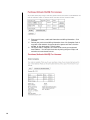
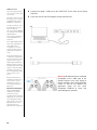
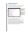
Audyssey MultEQ Pro
User Guide
for the Audyssey Sound Equalizer
Audyssey Laboratories, Inc, 350 South Figueroa Street, Suite 233, Los Angeles, CA 90071 www.audyssey.com
Table of Contents
Introduction ..................................................................................................................... 1
MultEQ Pro Setup Guide ............................................................................................................................. 1
License Keys ............................................................................................................................................... 1
Important Safety Precautions ...................................................................................................................... 1
The Audyssey Installer Kit ............................................................................................. 2
Setup Before Customer Installation .............................................................................. 4
MultEQ Pro Main Setup ............................................................................................................................... 4
Installing Microsoft .NET Framework 2.0 .................................................................................................... 4
Installing MultEQ Pro ................................................................................................................................... 4
Uninstalling MultEQ Pro .............................................................................................................................. 5
Viewing the Setup Guide ............................................................................................................................. 5
Add Microphone File to MultEQ Pro ............................................................................................................ 5
USB to RS232 Driver Installation ................................................................................................................ 5
Register on the Audyssey Installer Website ................................................................................................ 6
Audyssey Registered Installer ..................................................................................................................... 8
Purchasing and Activating MultEQ Pro Licenses ........................................................................................ 9
Custom Rackmount and Clamps ............................................................................................................... 12
Setup at Customer Installation Site............................................................................. 13
Preamplifier/Processor Connections to the Sound Equalizer ................................................................... 13
Amplifier Connections to the Sound Equalizer .......................................................................................... 14
Connecting Installer Kit Components ........................................................................................................ 14
Configuring the Preamplifier/Processor ..................................................................................................... 17
Before the MultEQ Pro Calibration......................................................................................................... 17
During the MultEQ Pro Calibration......................................................................................................... 17
The MultEQ Pro Application ........................................................................................ 18
Overview and Screen Sequence ............................................................................................................... 18
Welcome .................................................................................................................................................... 19
Product Selection....................................................................................................................................... 19
Job Information .......................................................................................................................................... 20
Options ...................................................................................................................................................... 20
Zone Configuration .................................................................................................................................... 21
Select a Zone............................................................................................................................................. 22
Room Dimensions ..................................................................................................................................... 22
Equipment Info........................................................................................................................................... 23
Measurement ............................................................................................................................................. 24
Before Measurements ............................................................................................................................ 24
Position 1 Measurement ........................................................................................................................ 25
Additional Position Measurements......................................................................................................... 26
Save and Load Measurements .............................................................................................................. 26
Detection Results....................................................................................................................................... 27
Table of Contents
Target Sound Options ............................................................................................................................... 28
Target Curve Designer & Target Curve Editor .......................................................................................... 29
The Target Curve Designer ................................................................................................................... 29
Using the Target Curve Editor ............................................................................................................... 30
Save Results ............................................................................................................................................. 33
Transfer the MultEQ XT Filters .............................................................................................................. 33
MultEQ XT On/Off demo ....................................................................................................................... 33
Change the MultEQ XT Filters............................................................................................................... 34
View Results – The Customer Certificate.............................................................................................. 34
Permanently Save the MultEQ XT Filters .............................................................................................. 34
Upload the MultEQ Pro Results............................................................................................................. 35
Appendix ........................................................................................................................ 36
Audyssey Recommended Demos ............................................................................................................. 36
Error Messages ......................................................................................................................................... 37
Device Not Detected .............................................................................................................................. 37
Input Signal Too Low ............................................................................................................................. 37
USB Connection Failure ........................................................................................................................ 37
Polarity Errors ........................................................................................................................................ 37
Disconnect Microphone ......................................................................................................................... 38
Warranties ................................................................................................................................................. 39
Audyssey Installer Kit ............................................................................................................................ 39
Audyssey Sound Equalizer.................................................................................................................... 39
Technical Support ..................................................................................................................................... 40
Notes ......................................................................................................................................................... 41
© 2008 Audyssey Laboratories, Inc.
Introduction
TM
The Audyssey Sound Equalizer is a stand-alone hardware platform for custom installers to implement
®
Audyssey MultEQ XT sound equalization technology in high-quality listening rooms using separate
amplifiers and preamplifiers.
The Sound Equalizer removes linear distortion (frequency response anomalies) caused by the interaction
of sound from loudspeakers within the room. This results in the playback of sound as it was intended,
without coloration, not just in one seat, but over a large listening area.
®
The installation of every Sound Equalizer requires professional calibration using the MultEQ Pro PC
application and the Audyssey Installer Kit. Installers take the Installer Kit and a laptop to an installation site,
run the MultEQ Pro application, perform measurements, and transfer MultEQ XT filters from the laptop to
the Sound Equalizer. The steps for completing this installation are described in detail in this User Guide.
This MultEQ Pro User Guide will help explain all of the capabilities of the Sound Equalizer. The User
Guide has been designed to alternate between instructions that are of primary importance and information
that provides additional detail in smaller type.
The latest MultEQ Pro User Guides for the Sound Equalizer and other Audyssey Installer-Ready products
are available to registered Audyssey Installers through the Audyssey Installer Website,
http://www.audyssey.com/InstallerWeb. After signing in, click on Downloads in the left pane to view
available documentation and software from the Audyssey Website.
MultEQ Pro Setup Guide
The MultEQ Pro Setup Guide is included in the Installer Kit package. This guide
provides simple instructions for the installation and activation of the MultEQ Pro
application. Be sure to review this guide prior to installing MultEQ Pro on a laptop or
PC.
License Keys
The MultEQ Pro application is used to calibrate the Audyssey Sound
Equalizer, and other Audyssey Installer-Ready products.
Although the Audyssey Sound Equalizer does not require a License Key to
calibrate using MultEQ Pro, other Audyssey Installer-Ready products may.
Consult your product’s user guide for more information.
License Keys may be purchased and generated by registered Audyssey
installers and are valid for a limited time after purchase through the Audyssey
Installer Website.
Important Safety Precautions
Every precaution has been taken in the design of Audyssey MultEQ Pro and the Audyssey Sound
Equalizer to ensure they are as safe as possible. Please review the following safety information before
attempting to calibrate an Audyssey Sound Equalizer.
•
Do not connect the Sound Equalizer to a power outlet that does not match the voltage input.
Verify the correct voltage level has been set by looking on the back of the unit above the power
connector. The marked square next to the voltage is the correct voltage. This voltage can be changed
if needed inside the box by changing switches on the DAE7-EQ PS board.
1
•
Do not exceed the limits of MultEQ Pro and the Sound Equalizer as given in the
specifications and other warnings provided in this manual.
•
Do not cascade other devices into the calibrated microphone-to-calibrated preamplifier-toSound Equalizer path. Serious damage could occur to each piece of equipment.
•
Do not connect the calibrated microphone to the 1/Mic input of the Sound Equalizer until
instructed to do so.
Doing so before completing the Product Selection screen as part of the MultEQ Pro application (see
Product Selection, page 19) will cause microphone feedback at levels that could damage the
speakers.
•
Do not connect a source, such as a DVD player, directly to the Sound Equalizer.
There are several reasons for this, but the primary reason is the difference in voltage levels. Most
sources provide 2 V RMS line-level output, and the Sound Equalizer has a maximum allowable input
level of 1.5 V RMS as is typical for high quality preamplifiers and processors. Connecting a source
directly may cause some material to clip the input of the Sound Equalizer. Additionally, you will not
have volume control, bass management, delay correction, or level correction. Therefore, to have
these features and achieve the correct input levels you should always use a pre-amp/processor
between the source and the Sound Equalizer.
The Audyssey Installer Kit
Every Audyssey Installer is required to purchase an Audyssey Installer Kit. More than one kit may be
ordered. The Audyssey Installer Kit contains the necessary equipment for calibrating an Audyssey Sound
Equalizer or Audyssey Installer-Ready products.
The Installer Kit contains several components that have been designed specifically for the Sound
Equalizer and are enclosed in a durable carrying bag.
Audyssey Installer Kit Contents:
2
•
MultEQ Pro Application Setup CD and Setup Guide
•
Calibrated ACP2 Preamplifier
•
Calibrated APM1 Microphone
•
Microphone Stand
•
Mini-XLR to RCA Adapter
•
Two Mini-XLR Cables (25 ft. and 50 ft.)
•
USB to RS232 Serial Cable
•
10 ft. USB Cable
Calibrated Microphone and
Microphone Stand
Each Audyssey microphone is
calibrated by Audyssey and comes
with a custom calibration curve that
matches the microphone to a highprecision, ¼” reference microphone.
The calibration curve for your
microphone is stored on your
MultEQ Pro application CD. The
absolute sensitivity, including the
exact gain of each individually
calibrated preamplifier, is included in
the correction curve, ensuring that
the trims reported by MultEQ Pro
will result in reference SPL playback
level.
Calibrated Preamplifier
This microphone preamplifier provides
phantom power to the microphone and
applies fixed gain amplification to the
microphone signal. It has no external
controls, making installation.
The microphone connects to the Mic In
mini-XLR jack. The Line Out mini-XLR
output connects to the back panel of
the Sound Equalizer 1/Mic input via
the mini-XLR-to-RCA Adapter. Use the
enclosed mini-XLR microphone cables
for both the Mic In and Line Out
connections to this preamp.
The laptop running the MultEQ Pro
application connects to the Sound
Equalizer via the 10 ft. USB cable.
The MultEQ Pro Application
and User Guide may be found
on the enclosed CD. A printed
Setup Guide is included in the
Installer Kit. The application
must be installed on your
laptop.
Warning: Only use the supplied Audyssey
calibrated preamplifier. Do not use any
other microphone preamplifier.
RCA to Mini-XLR Adapter
Warning: Only use the supplied
Audyssey Calibrated Microphone. Do not
plug in other microphones.
10 ft. USB Cable
MultEQ Pro Application
CD and Setup Guide
Use this adapter to connect the
Line Out of the mic preamplifier
mini-XLR cable to the 1/Mic
Input on the back of the Sound
Equalizer.
Microphone Mini-XLR Cables
The Installer Kit contains three 25 ft.
mini-XLR cables. The cables are used
to connect the microphone preamp
(from the Line Out interface) to the
Audyssey Installer-Ready device. The
cables can be linked together to
provide up to 75 feet of length for large
rooms or multi-room installations.
Warning: Do not connect the mic
preamplifier to the 1/Mic of the
Sound
Equalizer
until
the
instructed time (see Measurement,
page 24).
USB to RS232 Serial
Cable
Previous Installer Kits
This cable connects certain
Audyssey Installer-Ready
products to a laptop running
the MultEQ Pro application.
Items from previous versions of the
Audyssey Installer Kit (such as the
Audyssey
MM01
professional
calibration microphone) can still be
used for calibration with MultEQ Pro
v2.5 or later as long as the
microphone calibration file is copied
into the new Audyssey directory.
3
Setup Before Customer Installation
MultEQ Pro Main Setup
Insert the MultEQ Pro CD included in your Audyssey Installer Kit into your PC’s
CD-ROM drive.
Install Microsoft .NET
There are four possible options to choose from in the MultEQ Pro Main Setup
window (depending on the status of necessary installations). You will click on the
text itself to begin the operation desired.
•
Install Microsoft .NET
•
Install MultEQ Pro
•
Uninstall MultEQ Pro
•
View Setup Guide
•
Add Microphone File to MultEQ Pro
The options to Install MultEQ Pro will not appear unless Microsoft .NET 2.0 is
already installed.
Install MultEQ Pro
Installing Microsoft .NET Framework 2.0
Microsoft .NET 2.0 Framework must be installed before installing, uninstalling, or
running the MultEQ Pro software. The Microsoft .NET Framework is a software
component that can be added to the Microsoft Windows operating system.
The .NET 2.0 installation can be found on the MultEQ Pro CD. After inserting the
CD into your laptop, the ‘autorun’ function should launch the MultEQ Pro Main
Setup Window (see next page). If it does not automatically run, you can double-click
the disc (typically the D: drive) in the My Computer folder.
Accept the EULA
In the window above (Install Microsoft .NET), the option to install the MultEQ Pro
application is not available because Microsoft .NET (v2.0) is not installed.
Therefore, left-click on the Install Microsoft .NET option to begin the installation.
Note that during the installation process, highlighted items are shown with green
font. You must accept the End-User License Agreement (or “EULA”) to install the
.NET software.
It is highly recommended that the Windows Update is run after installation of .NET
Framework 2.0 in order to receive the latest service packs and security updates
from Microsoft. This is typically found by clicking the Start button and looking in All
Programs.
The option to install MultEQ Pro will only become available once .NET 2.0
Framework has been installed.
Installing MultEQ Pro
Select Installation Folder
Click Install MultEQ Pro to begin the installation wizard. The software installation
program will guide you through the MultEQ Pro application setup. You must accept
the Audyssey End-User License Agreement (or EULA) to continue the installation
the MultEQ Pro application. Select the location you would like to install the
application to or install to the default location.
Once the MultEQ Pro installation is complete, the software application will appear
in the “Audyssey Labs” folder in the Start menu (unless other location was
specifically specified by you). Repeat the above MultEQ Pro install for each laptop
your company will use for installations.
4
Uninstalling MultEQ Pro
A dialog with a progress bar will appear as the MultEQ Pro application is
uninstalled. The dialog will disappear once the uninstallation is complete.
Copied one file successfully
Viewing the Setup Guide
An electronic version of the MultEQ Pro Setup Guide is available to view at any
time during the setup.
Add Microphone File to MultEQ Pro
If your company has purchased more than one installer kit, it is highly
recommended you save the microphone calibration file from each of your MultEQ
Pro CDs on each company laptop used for installation. This allows measurement
microphones to be shared and used with any of your laptops.
After installing .NET & MultEQ Pro
The “Copied One File” window will be displayed after each microphone calibration
file is successfully copied to your laptop.
It is important to have the correct microphone calibration file with the corresponding
microphone and preamp marked with the matching 5-digit serial number. Each
microphone and preamplifier set is measured by Audyssey and the unique mic
calibration file is stored on the installation CD of the installer kit.
Locate and install driver software
Registered Installers may conveniently retrieve lost calibration files through the
Audyssey Installer Website.
USB to RS232 Driver Installation
Some Audyssey Installer-Ready products require the laptop running the MultEQ
Pro application connect to using the USB to RS232 connector provided in the
Audyssey Installer Kit.
In MultEQ Pro 3.0, and later, the driver to allow you to use the RS232 connector is
located on the MultEQ Pro Installation disc. Microsoft XP or Vista will prompt you if
needed to locate the driver. See Found New Hardware image.
Insert the MultEQ Pro setup disc
Select the option: Locate and install driver software (recommended).
A new window will launch asking you to insert the disc that came with your USB
Serial Controller. Insert the MultEQ Pro CD. It is advised to not search online for
the driver as it is included on the MultEQ Pro CD and the result may differ greatly.
If a Windows Security warning appears stating that it cannot verify the publisher,
select to, “Install this driver software anyway”.
Search online for driver?
Once the installation is complete, you will be able to use MultEQ Pro with the
RS232 connection. It is only necessary to perform this procedure once on a PC.
Windows Security
Install this driver anyway
5
Register on the Audyssey Installer Website
Before installing Audyssey products at a customer’s home, be sure to visit the
Audyssey Installer Website (A) at www.audyssey.com/InstallerWeb to register
your personal account.
A
B
You must register on the Audyssey Installer Website in order to:
6
•
Purchase and activate product licenses
•
Upload installation results and store customer certificates (B) (page 34).
•
Download updates for the MultEQ Pro software
•
Download user guides, manuals, and marketing materials
Enter your Username (typically your email address) and Password to enter the site.
If you have not yet registered on the site, and therefore do not have a Username &
Password, click the Register button and follow the instructions. Upon completion of
the registration process, you’ll be taken back to the Sign In page.
To register, you must already be an Audyssey installer with an Audyssey Installer
Kit. Each Installer Kit has an assigned 5-digit serial number, located in three places:
1. the lower right corner of the outer box the Installer Kit is shipped
2. front of the Audyssey Calibrated Microphone
3. back of the Audyssey Calibrated Preamplifier
After entering the serial number of the Installer Kit, click the Create New Account
button.
Enter the required information and click the Submit button. The Sign-In page will
follow.
7
Audyssey Registered Installer
After signing in, the Welcome screen gives a brief overview of the Installer Website.
Use the links in the left-hand column to navigate the site’s functions.
Certificate Overview
This page explains the details of the Customer Certificate.
Create Customer Certificate
Upload MultEQ Pro calibrations results to generate a Customer Certificate. At
completion of the intuitive process, certificates can be printed.
View Customer Certificates
View archived MultEQ Pro calibration results by clicking the View Customer Certificate
link next to the name assigned to each job (see Job Information, page 20).
Purchase/Activate MultEQ Pro Licenses
Purchase and manage your MultEQ Pro Licenses and License Keys.
Download Microphone Calibration Files
Retrieve lost Audyssey Microphone Calibration files using the 5-digit serial number
labeled on the mic.
Edit Account Settings
Change account settings such as Username, Password, Company Name, Address, etc.
Contact /Tech Support
Contact Audyssey with questions or comments.
Downloads
Download Audyssey support materials.
Privacy
Audyssey does not sell, license, or rent personal information gathered from this
Installer Website.
Sign Out
Sign out of the Audyssey Installer Website.
8
Purchasing and Activating MultEQ Pro Licenses
To perform a MultEQ Pro calibration for any Audyssey Installer-Ready product, you
must purchase a license and generate a license key for each unit you plan to install.
Sound Equalizer installations do not require a license key.
Audyssey Sound Equalizer installations do not require a license key.
Step 1 allows you to purchase a MultEQ Pro license. Step 2 assigns this license to
the specific serial or MAC number of the product you are calibrating, and creates
the license key for you to use at your customer installation.
Log on to the Audyssey Installer website at http://audyssey.com/InstallerWeb. Once
logged in, click Purchase/Activate Licenses on the left menu bar.
You may purchase licenses, view previously purchased licenses, and generate
license keys for installations all from this screen.
Step 1: Purchase New MultEQ Pro Licenses
1. The table below shows your previously purchased license keys and
displays (1) what model the key is for; (2) how many purchased keys you
have remaining that need to be activated.
2. Click Purchase New MultEQ Pro Licenses to make a purchase.
3. Choose the license type and quantity you wish to purchase. To purchase
multiple license types, click Add Row to add another line item to your order.
Once you have all the license types and quantities selected, click
Recalculate Totals to verify your total. Then click Continue.
9
4. Enter your full name, credit card information and billing information. Click
Continue.
5. Review your purchase and billing information, then click Complete Order. It
may take a few moments for your order to be processed. Don’t close the
window, or click the browser’s “Back” button.
6. Once your order is complete, an invoice will be sent to your registered
email address. You will have the choice of printing out your receipt, and
activating your purchased licenses.
10
Change License Types
You can convert any license type to any other Installer-Ready product from the
same manufacturer. You must do this before activating a purchased key (see Step
2).
1. Underneath the “Purchased Licenses” table, click on Change
License Types.
2. Use the drop down menu to choose to which model number you
would like your license transferred.
Step 2: Create a Key
Activating a purchased license will generate a license key. These keys are tied to
each unique Installer-Ready product, and must be input every time a MultEQ Pro
calibration is performed on that product. License keys have unlimited use and do
not require you to repurchase if you recalibrate. However, these keys do expire in
30 days and can be regenerated free of charge.
Key Expiration& Regeneration
Keys expire after a period of 30 days. The license however, never expires. If a key
expires, you can generate a new key at the Audyssey Installer website.
11
1. Depending on the manufacturer, you must enter the serial number
or MAC address for the unit. If you do not enter the correct number,
an incorrect license key will be generated. Serial numbers and
MAC addresses are case sensitive, and be careful not to enter
extra spaces.
Custom Rackmount and Clamps
Middle Atlantic Products carries a custom rackmount with clamps for the Audyssey
Sound Equalizer.
If you are a Middle Atlantic Products dealer, contact your account representative.
To become a Middle Atlantic Products dealer, please visit their website at:
www.middleatlantic.com
12
Setup at Customer Installation Site
Preamplifier/Processor Connections to the Sound Equalizer
Before proceeding, the Sound Equalizer, amplifier(s) and preamplifier/processor
should be powered off.
The Sound Equalizer 1/Mic
Input has two functions:
Make the necessary audio connections between the outputs of the
preamplifier/processor and the ANALOG INPUT channels of the Sound Equalizer.
1 It is the input for the
calibrated microphone
during calibration
Warning: Do not connect the calibrated microphone to the 1/Mic input of the
Sound Equalizer at this time. Doing so before you complete the Product Selection
screen as part of the MultEQ Pro application (page 19) will cause microphone
feedback at levels that could damage the speakers.
2 It is the channel 1 audio
input that connects to
the line-level audio
output of the
preamplifier/processor
(usually the left channel)
1/Mic
ANALOG INPUT
1/Mic
3
5
7
13
Mini-XLR cables
The Installer Kit contains
two mini-XLR cables. One
mini-XLR cable is used to
connect the microphone
preamplifier to the Sound
Equalizer and the other is
used to connect the mic
preamp to the Sound
Equalizer.
The length of cable
needed depends on the
size of the customer’s
room and/or the number
of zones being installed.
Additional mini-XLR
cables may be purchased
separately for a longerlength connection
(See Zone Configuration,
page 21).
Amplifier Connections to the Sound Equalizer
Make sure that the Sound Equalizer, amplifier(s) and preamplifier/processor are
powered off before continuing.
Make the necessary audio connections between the ANALOG OUTPUT channels
of the Sound Equalizer and the inputs of the amplifier.
The Sound Equalizer has eight input and output channels that can be assigned in
any way you choose. To simplify keeping track of the assignments, Audyssey
recommends the standard SMPTE channel layout:
1: L
3: C
5: LS
7: LBack
2: R
4: Sub
6: RS
8: RBack
If installing multiple systems for different zones, the necessary connections should
be made to all amplifiers and speakers for each zone at this time. When you begin
using the MultEQ Pro application, you will be asked to select which channels are
assigned to the assignable inputs and outputs of the Sound Equalizer (see Zone
Configuration, page 21).
Each zone is calibrated separately using the MultEQ Pro application (see Select a
Zone, page 22)
ANALOG OUTPUT
1
3
5
7
Connecting Installer Kit Components
See connection diagram on next page.
14
A
Connect one of the mini-XLR cables to the microphone.
B
Place the microphone stand upright and extend the boom arm. Attach the
microphone holder to the end of the boom arm. Insert the microphone in a
vertical position in the holder so that it is pointed to the ceiling.
C
Connect the mini-XLR cable from the microphone to the microphone MIC
IN input on the preamplifier.
Microphone Position
Place the microphone in a
vertical position with the
capsule pointing directly at
the ceiling for all room
measurements. Make sure
there are no nearby
obstructions or large
reflecting surfaces.
Make sure that the first
microphone position is
located at the main
listening seat. This is
where the delays and trims
will be calculated.
Connection Diagram
15
USB Connection
Any of the laptop’s USB
ports may be used for this
connection.
The USB connection gives
the laptop control over the
Sound Equalizer during
MultEQ Pro calibration.
Provide enough slack for
the USB cable so that it
will not suddenly
disconnect during MultEQ
Pro calibration. Accidental
USB disruption/
disconnection will likely
require MultEQ Pro be
restarted.
D
Connect the laptop’s USB port to the USB PORT on the back of the Sound
Equalizer
E
Leave the mini-XLR-to-RCA adapter disconnected for now.
D
The supplied USB cable is
10 ft. long. Substitution of
other USB cable is
acceptable for a longer
connection (the longest
USB cables available are
15 ft).
If performing multi-room
or multi-floor installations,
an active extension or hub
may be used to extend
USB length. An Ethernet
Extender may be used as
a bridge between two USB
cables so that the laptop
maintains connection to
the Sound Equalizer while
moving from room to
room.
Ethernet extenders are
available in lengths up to
150 ft. Please contact
Audyssey for a list of
recommended Ethernet
Extenders.
Mini-XLR-to-RCA Adapter
During the MultEQ Pro
calibration you will be
required to use the
included mini-XLR-to-RCA
adapter (E) to connect the
mic preamplifier’s LINE
OUT output to the Sound
Equalizer for the room
measurements (see
Measurement on page 24).
16
E
Warning: Do not connect the calibrated
microphone to the 1/Mic input of the
Sound Equalizer at this time. Doing so
before completing the Product Selection
screen as part of the MultEQ Pro
application (page 19) will cause
microphone feedback at levels that
could damage the speakers
Configuring the Preamplifier/Processor
The MultEQ Pro application is responsible for measuring the room response and
computing the complex equalization filters for the room. The speaker type,
crossover frequency, level, and trim settings reported by the application must be
entered manually in the preamplifier/processor.
Before the MultEQ Pro Calibration
If the subwoofer has a built-in lowpass filter it should be bypassed, or set to the
THX setting. Sometimes there is an input called “LFE” that has the lowpass filter
already bypassed. This must be done before MultEQ Pro measurements are made.
If the subwoofer lowpass filter cannot be defeated, set it to its maximum frequency.
Any subwoofer gain controls should be set to their nominal settings, such as at the
THX position, or at 12 o’clock on a conventional level control. Phase controls, if
they exist, should be set to 0°.
If the subwoofer has any sort of “Auto”, “Standby”, or “Sleep” mode that turns the
power to the subwoofer off after it does not receive any signal for some period of
time, disable this mode. This will ensure that the subwoofer is always on and ready
to output the MultEQ test signal. Failure to disable this mode could chop off the start
of the test signal and this would result in inaccurate subwoofer measurements.
During the MultEQ Pro Calibration
The Audyssey Sound Equalizer not only performs room equalization, it also
measures various parameters that must be set within the preamplifier/processor so
that the playback system is calibrated. MultEQ Pro measures the distance from
each loudspeaker to the primary microphone location (or position 1), the
recommended optimum crossover frequency for each channel to the subwoofer, the
level trim for each loudspeaker channel, and the absolute polarity of each
loudspeaker.
Defeating the lowpass filter
in the subwoofer ensures
that the MultEQ Pro
software has the best
possible chance of
producing the smoothest
response through the
crossover region because
the only filter to be applied
is the one in the bass
management system of the
pre/pro.
The crossover frequency in
surround controllers often
defaults to 80 Hz. MultEQ
Pro examines solutions
across a range of
frequencies to optimize the
match between subwoofer
and satellites both in
magnitude and in phase.
This often results in a
different recommendation,
but results in a smoother
amplitude and phase
crossover blend.
Consult the manufacturer’s documentation of the preamplifier/processor on how to
manually set the parameters reported by the MultEQ Pro application in the
Detection Results Page (page 27)
17
The MultEQ Pro Application
Overview and Screen Sequence
The MultEQ Pro application consists of a series of screens which leads
installers through the calibration process. Each screen of the application is
listed in the left column of the application (B) to help track progress.
A
Product Selection
D
Job Information
Options
Zone Configuration
B
Room Dimensions
Equipment Info
Measurement
Detection Results
Target Sound Options
Save Results
C
The MultEQ Pro version number is listed at the top right of the screen (A)
The current screen is highlighted in bold within the list (B).
Move forward and backwards through the application’s screens by clicking
the back (◄) and forward (►) buttons on each screen (C).
While the mouse cursor is over the forward and back buttons (C), black ◄ /
► buttons indicate available back and forward functionality, while light grey◄
and ► buttons indicate that forward or back are currently unavailable.
Product Selection, Job Information, Options, and Zone Configuration (D) are
encountered only once during a session. The remaining screens (E) are
encountered once for each zone that requires calibration.
18
E
Welcome
Introduction to the MultEQ Pro application.
Product Selection
Choose Audyssey Sound Equalizer from the list of Audyssey products and press
the ► button.
Product Selection
MultEQ Pro supports
multiple products from
various manufacturers.
The MultEQ Pro
application screens that
follow are common to
most Audyssey InstallerReady products. Some
functions may vary so it
is important to review
the product’s specific
User Guide.
19
Job Information
This information is used
to manage customer
calibration results on the
Audyssey Installer
Website (page 6).
Calibration results and
customer certificates are
listed on the Audyssey
Installer Website by the
customer or job name
entered at the Job
Information screen.
Options
The importance of
microphone calibration
is often overlooked.
Even the highest quality
micro-phones often
contain small variations
that cause measurement
artifacts. As part of
preparing the Installer
Kit, Audyssey measures
each microphone
individually and stores a
unique calibration file on
each MultEQ Pro
application CD. This file
ensures that the MultEQ
Pro room correction
filters take into account
the frequency response
variations of each
individual microphone
used for calibration.
In the case that multiple
Installer Kits are
available (more than one
micro-phone), it is
important to choose the
correct serial number for
the microphone in use
during installation.
If the serial number
listed in the menu does
not match the serial
number on the
microphone you are
using, contact Audyssey
technical support (p. 40).
If you have more than
one Installer Kit, it is
highly recommended
that you install the mic
calibration curve file
from each Kit’s MultEQ
Pro Installation CD on
each of your laptops.
This way everyone at
your company can share
Installer Kits.
20
Job Information
Enter the customer or job name in the Customer or Job Name fields.
Enter your name in the Technician’s Name field
Options
Choose which microphone you are using from the menu under the
Microphone heading. Select the microphone that has the serial number
matching the serial number on the microphone you are using.
Zone Configuration
The Sound Equalizer performs equalization for up to eight audio channels. These
eight channels can be assigned to zones.
Multiple Subwoofers
The Sound Equalizer
supports multiple
subwoofers. In fact, all
eight channels can be
used for subwoofer
correction if so desired.
Use of multiple subwoofers operating from
various positions in the
room can smooth the bass
response.
There are two ways to
connect multiple
subwoofers.
Use the Channel grid to select which channels you are assigning to each zone.
Each column represents a possible zone. For example, if you are calibrating a 7.1
system, then all eight radio buttons in the first column should be selected and each
channel should be assigned from the drop-down menu.
If calibrating two zones (one with a 5.1 system and one with a 2.0 system), then you
should select the first 5 buttons in the first column, and the last two buttons in the
second column. The channels in the second column should be named Left Front
and Right Front.
Finally, if you are calibrating four two-channel stereo systems in different rooms,
select two radio buttons in each of the first four columns.
If the pre/pro has an
advanced bass
management system that
directs bass from different
channels to a separate
subwoofer, then each
subwoofer output should
be connected to a separate
Sound Equalizer channel.
In such systems, the delay
and trims calculated by
MultEQ Pro can be entered
in each individual
subwoofer setting in the
pre/pro.
The most common
configuration for
preamplifier/processors
that provide multiple
(usually two) subwoofer
output connectors is to
have them internally
connected in parallel (ycord). In such cases, it is
not possible to enter
separate delays and trims
for each subwoofer. In
this case, connect ONE of
the subwoofer outputs
from the pre/pro to ONE
input channel of the Sound
Equalizer and then attach a
Y-cord to the
corresponding output
channel to feed the signal
to each subwoofer. In this
situation, it is best to place
the subwoofers in
symmetrical locations at
equal distance from the
main listening position
If the subwoofers can not
be placed in symmetric
locations, Audyssey
recommends using a delay
that is the average of the
distances from the
subwoofers to the
principal listening location.
21
Select a Zone
Note: The Select a Zone screen only appears if you have assigned more than one
zone to the Sound Equalizer at the Zone Configuration screen, page 21.
The numbers in the Channel column correspond to the channel numbering for the
Sound Equalizer. This may be different than the numbering on the back of the
pre/pro. The information in the Speakers column corresponds to the type of speaker
assigned to each Sound Equalizer channel on the Zone Configuration screen.
Confirm that this information is correct before continuing.
Decide which zone to calibrate by selecting the button next to the Zone. Zones may
be calibrated in any order.
After finishing the calibration for a zone, click the ◄ arrow to return to this screen to
calibrate any remaining zones. See Save Results, page 33.
Room Dimensions
It should be explained to
customers that if the
layout of the room
changes, a recalibration
will be necessary to
create MultEQ XT filters
that match the room’s
new configuration. This
is because the room’s
configuration influences
the performance of loudspeakers and therefore,
the frequency response
throughout the room.
Surfaces such as walls,
the ceiling, the floor, and
furniture distort sound
playback throughout the
room.
Room Dimensions
Input the dimensions of the customer’s room by clicking the up/down arrows next to
each data field. Select from English or Metric units (feet or meters).
Note
This screen will need to be completed for each of the zones.
If desired, manually calculate and write down the volume of the room (Area x
Height) to help select an Audyssey target curve later. See Target Sound Options,
page 28).
The information entered at this screen may be stored on the Audyssey Installer
Website account and will not affect filters created or saved to the Sound Equalizer.
22
Equipment Info
Enter information about the customer’s audio equipment.
Note: Enter this information for each zone.
The information entered at this screen is stored on the Audyssey Installer Website
account (see page 6) and will not affect filters created or saved to the Sound
Equalizer.
Equipment Info
High-quality loudspeakers
are spectrally matched at
the factory, meaning they
have very close to the
same frequency
response.
However, each
manufacturer has
different tolerances and
standards when
spectrally matching their
speakers. Besides room
equalization, one of the
main improvements of
MultEQ Pro is equalizing
the frequency response of
speakers so that they are
spectrally matched. This
is why it is important to
recalibrate your
customer’s system even if
they replace one of their
speakers with one of the
same model.
Why is it important to
have spectrally matched
speakers? The ability for
us to create sound
images in our brain and
perceive sound coming
from places in the room
where the speakers aren’t
located, depends on the
spectral information
coming to our ears in a
symmetrical way.
By equalizing speakers
that aren’t exactly
spectrally matched, you
are improving imaging
and soundstage.
23
Before Measurements:
The microphone should
be positioned as far out
from the stand as possible
to minimize the effect of
stand reflections. The
microphone has been
calibrated at grazing
incidence and should
point to the ceiling.
Measurement
Incorrect
Correct
Before Measurements
Review the following guidelines:
The room measurement
process plays a series of
full-bandwidth test signals
through each channel to
measure the room’s
response. Audyssey has
designed the test signals so
that several thousand
measurement samples are
collected.
During room measurement,
some channels may repeat
the series of test signals at
a louder volume. This is
done to overcome
background noise problems
and achieve the required
signal-to-noise ratio for
creating precise room
correction filters. The level
trim calculation is not
influenced by the increase
in test signal level.
24
1
Some subwoofers have a standby mode. Be sure to turn this
function off before measuring (see Before the MultEQ Pro
Calibration, page 17)
2
The microphone should be placed in a vertical position (grazing
incidence) for all measurements.
3
Connect the mini-XLR cable from the microphone preamp LINE
OUT to the 1/Mic input of the Sound Equalizer using the mini-XLRto-RCA Adapter
4
Quiet the room as much as possible. Background noise can disrupt
the room measurements. Close windows, silence cell phones,
televisions, radios, air conditioners, fluorescent lights, home
appliances, light dimmers, or other devices.
5
Refrain from talking during measurements. Do not sit or stand
directly between any of the speakers and the microphone during
the room measurements. Each speaker emits a series of test
signals during the measurements. Obstacles between speakers
and the microphone, and background noise can disrupt the
microphone’s ability to record the room response to the test signals.
The room measurement
process plays a series of
full-bandwidth test signals
through each channel to
measure the room’s
response. Audyssey has
designed the test signals so
that several thousand
measurement samples are
collected.
Position 1 Measurement
For the Position 1 Measurement, place the microphone at the
primary (or most center) listening location. The microphone
should be positioned at ear height of a sitting listener. It is
important to have the microphone in the primary listening
position for the first measurement so that delays are
calculated correctly (see Detection Results, page 27)
Press the Measure button. The Audyssey test signal will play
a series of ten chirps through each channel. The text under
the status bar indicates which channel is currently being
measured.
Note: The microphone tip should always point directly to the ceiling.
After the test signal is finished playing, the application will transfer each
channel’s measurement from the DSP in the Sound Equalizer to the
computer for further processing. This takes several seconds.
Click Undo Last to erase the previous measurement.
Click Clear All to erase all of the previous position’s measurements and start
over at Position 1. The following window will appear if you click the Clear All
button.
During room measurement,
some channels may repeat
the series of test signals at a
louder volume. This is done
to overcome background
noise problems and achieve
the required signal-to-noise
ratio for creating precise
room correction filters. The
level trim calculation is not
influenced by the increase in
test signal level.
The Position 1 measurement
is different from the other
position measurements that
follow. Every position
measurement measures the
room’s frequency and time
response at that particular
position. But Position 1 also
detects the absolute polarity
of each speaker, calculates
the exact acoustical
distances (within half an
inch) for setting delays, and
determines levels (within
half a dB) for each
loudspeaker. The polarity,
distance, and level from the
Position 1 Measurement are
displayed later on the
Detection Results screen
where you will manually
input the data into the
preamplifier/processor (see
page 27).
Audyssey calculates the
optimum bass crossover
frequency for each speaker.
These are often different
from the spec provided by
the manufacturer. MultEQ
Pro calculates the optimal
frequency based on all of
your position measurements
and displays it on the
Detection Results screen.
The most accurate method
of determining the correct
crossover frequency is
through room measurement.
This is because room
acoustics significantly affect
the low frequency
characteristics of
loudspeakers.
25
Audyssey has a crossoverfinding method that is based
on the measurement of each
satellite and subwoofer in the
system at multiple seats in
the room. The frequency that
best optimizes the blend
between the satellite and
subwoofer is selected based
on complex addition
(amplitude and phase). The
crossover calculation takes
into account the capabilities
of the speaker to make sure it
isn’t overdriven. This
frequency can be different for
each channel if each speaker
is driving the room from a
different location.
If the loudspeakers are set up
as dipoles for playback, then
they MUST be calibrated in
dipole mode. Calibrating a
loudspeaker as a direct
radiator and then setting it to
dipole mode will give
incorrect results.
Most home systems use a
single loudspeaker per
surround channel. If more
speakers are desired to
increase the coverage in a
large room, it is best to use a
fairly large number. Simply
having two speakers per
channel leads to audible
comb filtering.
AAA or AA batteries can be
used to test the polarity of a
speaker. Simply connect the
negative end of the battery to
the negative speaker lead
(with the amplifier
disconnected), and tap the
positive speaker lead to the
positive end of the battery. If
the woofer moves out of the
speaker cabinet, then the
polarity of the speaker cable
is correct. If the woofer pulls
into the speaker cabinet, the
speaker cable polarity is
reversed. You should only be
touching the woofer, never
the tweeters.
If you ignore the speaker
polarity error message and
continue with the application,
then you must rerun the
application and recalibrate the
system if you change the
speaker polarity after MultEQ
is finished.
26
Additional Position Measurements
Move the microphone to another listening position and press the Measure button.
Repeat the process for several positions in the main listening area of the room. It is
required to measure a minimum of three positions before continuing. Audyssey
strongly recommends measuring at least 8 positions for average-sized rooms.
Stagger the height of the microphone by a few inches from one measurement
position to the next to account for the varying heights of listeners.
The larger the room, the more positions should be measured up to a maximum of
32 positions. Be sure to measure only in locations within the main listening area, but
try to avoid extreme off-axis positions. Measuring in a distant corner of the room will
not be beneficial and will detract from the overall benefit within the main listening
area.
Audyssey MultEQ Pro measures the absolute polarity of each individual
loudspeaker. If any of the speakers are wired out of polarity, the application will
display an error window that explains which loudspeaker(s) to check. You may then
verify the polarity problem before continuing with the application. This is especially
useful when you are installing in-wall speakers. It is recommended that you check
for polarity problems by examining the wire connections at the amplifier, speakers
and in-wall splices.
Click the ► button to complete the measurement process. The window below
appears after clicking the ► button.
Note: You can always return to the Measurement screen and measure additional
positions by clicking the ◄ arrow (the application will remember the last measured
position).
Save and Load Measurements
After the first successful measurement is obtained, the Save Measurements button
becomes available. You may save your current progress by pressing the Save
Measurements button. The “Save As” Window is launched
The default directory, “My Documents\Audyssey\Measurements” is used to save
and load measurement files with the file extension, “.amd”.
When saving measurements, it can be helpful to enter a name for the file that will
help you find the file for future use.
Load Measurements at any time while at the Measurement screen. Simply press
Load Measurements and open the file that you wish to load.
Important Note!
Use measurement files from the same device as you are loading to. Also it is
important make a note of the Zone Configuration settings used when the saved
measurement file was created.
Be sure to enter the same Zone Configuration settings as used in creating the
measurement file you are about to load. Otherwise, the final results will be
inaccurate.
MultEQ Pro will provide a warning message if these settings do not match.
Detection Results
This screen displays the speaker Distance and Trim results derived from the
Position 1 measurement, and the recommended crossover derived from all
measurements. MultEQ Pro lists individual, suggested speaker crossovers in
decreasing order of performance.
Note: You must manually
enter the information on
this screen into the
preamplifier/processor’s
settings.
Speaker Type indicates whether the detected loudspeaker is a satellite or subwoofer.
Distance may be displayed in either English (feet) or Metric (meters) units by clicking the
“Dist” heading (in blue). By default, the values are shown in feet, and must be used to
manually set the distance (delay) in the pre/pro. When entered, the settings shown will timealign all satellite speakers and subwoofers to the same point (Position 1).
Trim is displayed in dB. This number is not a dB SPL number; it is a relative Trim. The Trim
information must used to configure the level trims in the pre/pro. Using the exact numbers
shown will ensure that playback with the volume knob at “0” on the pre/pro will be at
reference level. If the values shown are out of the adjustment range provided by the pre/pro
you can subtract a fixed number from each one of them and enter the resulting values.
Reference level playback may not be possible in this case, but most consumers listen at 10
dB (or more) below reference so this will not be a problem.
The Sound Equalizer expects the connected source to be 1.5 V reference level. If connected
to a 2 V reference source, lower the trims entered into your processor by 2.5 dB.
Crossover is displayed in Hz. Use these numbers to enter the crossover frequency for each
of your speakers. The Sound Equalizer does not apply crossovers. It suggests what value to
use for each channel in the bass management system of the preamplifier/processor. The
crossover recommendations are derived from the room measurements and are optimized for
the in-room response of the speakers. They are listed from top to bottom of the drop-down
menu. The top-listed number is the highest recommended crossover setting. Other values
below it are also possibilities, but have lower recommendation scores. Depending on your
pre/pro, follow one of the following three steps:
1.
If your preamplifier/processor allows for individual speaker crossover settings, input
the first crossover listed for each speaker.
2.
If your preamplifier/processor pairs the crossover settings for your front and
surround speakers, find the best recommended crossover shared by your Left Front
and Right Front speakers using the drop-down menus in MultEQ Pro. Input that
crossover as your “Front” speaker crossover setting on the preamplifier/processor.
Use the same method for your surround speakers.
3.
If the preamplifier/processor only allows one crossover setting for the entire system,
use the first crossover number MultEQ Pro lists for the center channel.
Note: The Audyssey filter calculation is optimized based on your selected crossover
frequency setting in the “Crossover” drop-down menus. Make sure you select the same
crossover frequency as what you enter into the preamplifier/processor. If you do not, then the
subwoofer to satellite “splice” or transition region will not be optimally flat. Namely, there may
be frequency response peaks and dips that will negatively affect the sound quality.
The “Large” setting should only be used if there is no subwoofer detected or if the low
frequency capability of a speaker extends below 40 Hz.
Detection Results
In some cases there may be
excessive low frequency
noise in the room not
necessarily audible to the
human ear, but picked up by
the microphone. This may be
due to rumble from the
street or HVAC equipment
that generates structureborne noise in the building.
This may cause the
subwoofer, and possibly
other loudspeakers, to be
detected at an incorrect
distance. If this happens,
and the low frequency noise
cannot be reduced, the only
option is to use a tape
measure to measure the
distances.
Occasionally the subwoofer
distance will be found to be
greater than the actual
measured distance. This is
due to the delay that the
subwoofer low-pass filtering
circuitry introduces.
Although the physical
distance may be shorter, the
MultEQ Pro-measured
distance is in fact correct.
If you have connected the
Sound Equalizer output to
another digital signal
processor that adds delay to
the signal, the distances
measured by MultEQ Pro
may be greater than the
actual distance. If the
distances are off by only a
few feet, you may still use
the distance measured by
MultEQ Pro. If they are
excessively off (5’ or more),
you may need to bypass the
device causing the delay, or
determine if there is a
setting that can reduce the
delay caused by the other
component.
Crossover
You may select your own
crossover values for each
speaker in the pre/pro.
However, Audyssey
recommends using the
displayed crossovers on this
screen. This is because the
most accurate method of
determining the correct
crossover frequency is by
room measurement. Room
acoustics affect how far the
speaker can actually play in
the room.
27
Target Sound Options
To cover a wide range of
room types, MultEQ Pro
currently provides a
selection of four target
curves.
Target Sound Options
Choose which Audyssey target curve you want to use by selecting from the Target
Sound Options menu.
Flat curve creates
equalization filters that
correct the response to
flat, from the low frequency
cutoff point that MultEQ
Pro has determined, to the
upper frequency limit of the
tweeters. This setting must
be used in a THX system in
order to allow THX reequalization to operate as
it was intended. It is also
recommended for very
small or highly treated
rooms in which the listener
is seated close to the
loudspeakers.
High Frequency Roll Off 1
curve introduces a slight
roll off at high frequencies
that accounts for the
balance between direct and
reflected sound for small to
medium size rooms (room
volume less than 2500 cu.
ft.)
High Frequency Roll Off 2
curve introduces a
slightly greater roll off at
high frequencies,
restoring balance
between direct and
reflected sound for
medium to large size
rooms (room volume
between 2500 and 5000
cu. ft.)
SMPTE 202M curve is an
international standard for
the high frequency roll-off
applied in a typical 500seat movie theater. It is
appropriate for
professional mixing spaces
and dubbing stages that
must be calibrated for film
sound postproduction. It
can also be used in
extremely large playback
spaces (room volume
greater than 5000 cu. ft.)
28
Midrange Compensation
It is recommended that you engage the Midrange Compensation option for your first
listening test (this is selected by default). Midrange compensation is sometimes
necessary to correct for the directivity differences that often occur in that frequency
range due to the crossover circuitry or horn-loaded speakers. You can later return
to this screen and disengage this option if you prefer.
Design
Press the Design button to launch the Target Curve Designer feature.
Click the ► button to calculate your correction filters when you are ready to proceed
to the next screen.
Disconnect the Microphone Preamplifier
After the ► button is pressed, a warning will appear to check that the Microphone
preamplifier mini-XLR cable has been removed from the 1/Mic input of the Sound
Equalizer.
Warning: You must remove the
calibrated preamplifier’s mini-XLR-toRCA connection from the 1/Mic input
of the Sound Equalizer before
continuing. Leaving the microphone
connected will cause feedback at
levels that could damage the speakers.
Target Curve Designer & Target Curve Editor
Channels
Edits
Grips
Cursor Location
The Target Curve Designer is launched by pressing the Design button of the
Target Sound Options screen (page 28). Be sure to click the radio button of the
target curve selection you want to edit, as that is the target curve you will see
when editing.
Edits applied to one or more channels affect all target sound options shown on
the Target Sound Options screen.
The Target Curve Designer
After pressing Design, a window labeled Target Curve Designer appears. Press
the Add New button at the lower left corner of the window. The first edit will
appear as “filter1.csv”. Click the Edit button (to the right of, “filter1.csv” below) to
begin editing
The Target Curve Designer Window
29
Using the Target Curve Editor
A new window is launched called the Target Curve Editor that shows the selected
target curve from the Target Sound Options screen. In this image, the High
Frequency Roll Off 1 target curve is shown without Midrange Compensation selected
(see Target Sound Options, page 28).
The blue line represents your current edits. The red line shows how the target curve is
affected by the current edits.
Placing and Adjusting Grips
Grips allow installers to adjust target curves as they see fit. They appear as blue
squares on the blue line, or green when highlighted.
There are two methods for adding grips. The first is using your mouse. The second is
by manually typing in where you want to place a grip using the text entry boxes at the
bottom left corner of the Target Curve Editor window.
To add a grip by manually typing it in, left click in either of the two cells (frequency or
gain) and type the values to enter a grip in. Press enter when you have entered both
values. The grip then appears in the graph above
Two grips are already present at each side of the graph by default. These two grips
can never be moved horizontally, or deleted. However, they can be raised and
lowered.
Additional grips can be placed along the blue line by simply left clicking on, above, or
below the blue line. Grips can be placed within the graph from +3 dB to -3 dB from 0.
This area is highlighted below. If you place the grip outside of this range, it will be
created at the nearest allowed range at the frequency in line with where your cursor is
located.
Valid Range for placing Grips
30
Once a grip has been placed, it can be moved by left clicking and holding the mouse button
while dragging with your cursor. The grip may be moved in any direction. This edit
immediately affects the blue and red lines. Grips cannot be moves outside of the valid range
shown on page 40, and cannot be placed too close to another grip.
Spend some time working on placing grips and moving them to get a sense of how to best
build your edit. Create several grips and move them in relation to each other, avoiding sharp
peaks.
Working with Grips
A grip is selected by simply left-clicking on the grip. It will turn green to show it is the selected
(highlighted) grip. With the left mouse button held, you can drag the highlighted grip in any
direction. While holding the CTRL key, you can highlight multiple grips and move them as
one group.
To delete a grip, right click on the highlighted grip or group and select the option to Delete
Points.
To adjust a grip through text entry, right click on the grip and select Enter Point Values. The
frequency cell at the left bottom of the screen becomes highlighted and is ready for you to
manually type in the exact desired frequency you wish the grip to be located at. Press the tab
key to highlight the next cell on the right (or left-click in that cell). Enter the gain you wish to
use (+3.0 dB to -3.0 dB) and press Enter. The grip will move to the new location you entered.
To complete your edit, click the OK key at the bottom right corner of the window. Or to delete
your edits, press the Cancel button adjacent. The Target Curve Editor window will close.
31
Saving Your Work
If you have accepted the edits by previously pressing the OK button, you may now
assign them to one or more channels using the radio buttons to the right of the edit
you created (radio buttons 1-8). Each channel here corresponds to the channels
you selected at the Zone Configuration screen. Be sure to be aware which edits you
assign to which channels.
The Save button becomes available after accepting edits. Click the Save button
(alongside the latest accepted Edit) to save this edit as a .csv file.
The Save As window launches. The save location defaults to the “My
Documents\Audyssey\Measurements” folder of your computer. However, you
may save the files wherever you like as shown above. It is advisable to change the
name of the file so that you will remember the purpose of your edit.
You may load any saved csv file while viewing the Target Curve Designer window
and pressing the “Load…” button. This same folder will be launched.
32
Save Results
Once the room
measurements are
completed, MultEQ Pro
calculates an equalization
filter for each loudspeaker
channel, including the
subwoofer. These filters
achieve a particular
frequency response within
the entire listening area for
each loudspeaker. This
target frequency response is
determined based on several
acoustical and program
material considerations and
is called a target or
calibration curve.
Before proceeding, connect the correct preamp/processor output to the 1/Mic INPUT of the
Sound Equalizer as shown below.
1/Mic
3
ANALOG INPUT
5
7
Transfer the MultEQ XT Filters
Transfer the correction filters you have calculated to the Sound Equalizer by
clicking the Transfer to Sound EQ button. This process only temporarily stores
the filters in the Sound Equalizer so you can listen to them before deciding to
permanently save them. Previously saved filters will not be erased until you click
the Save Permanently to Sound EQ button. The Sound Equalizer can only store
one set of filters at a time.
The Transfer to Sound EQ process may take several minutes depending on how
many channels and how many positions were measured. The download status
bar will indicate the progress of the transfer.
MultEQ XT On/Off demo
After the results are transferred to the Sound Equalizer, the Turn MultEQ On
and Turn MultEQ Off buttons will become available. You can use these buttons
to demo the MultEQ XT filters before deciding to save them permanently to the
Sound Equalizer.
Contrary to popular belief, a
target curve that is flat from
20 Hz to 20 kHz is not always
the one that will produce the
correct sound. There are
several reasons for this
including the fact that
loudspeakers are much more
directional at high
frequencies than they are at
low frequencies. This means
that the balance of direct and
room sound is very different
at the high and low ends of
the frequency spectrum.
MultEQ XT uses a
proprietary clustering
method to combine room
measurements, allowing for
more precise measurements
over previous room
correction methods. This
clustering approach allows
the MultEQ XT filters to
perform the most
appropriate correction for all
listening positions. MultEQ
XT looks at the room
responses at each
measurement position and
clusters them into groups
based on the similarity of
their patterns and the
severity of their acoustic
problems. This clustering is
not exclusive, each response
can belong to more than one
cluster with a certain
probability. From the
responses in each cluster, a
representative response is
created. From the group of
representative responses, a
“master” response is
created, representing each
“constituent” response in
the best possible way.
33
MultEQ XT On/Off Demo
If a customer is present
during the MultEQ On/Off
demo, have them sit
within the room area
measured earlier. If they
are not positioned inside
this area, it is less likely
that they will hear the full
effect of the MultEQ XT
filters.
Audyssey recommends
using the demo material
detailed on page 36 for
MultEQ XT demonstration
to customers.
The Customer Certificate
Until the filters are
permanently committed
to the Sound Equalizer,
only a draft version of the
Customer Certificate is
available to view. This is
clearly shown by the text
“DRAFT” over the
certificate.
Note: The red EQ button on the front of the Sound Equalizer can be used to
turn MultEQ on and off. A Green light on the front panel indicates that the
MultEQ XT filters are engaged and a red light indicates that MultEQ XT is
bypassed.
It is highly recommended that you follow the Audyssey instructions for
demonstrating MultEQ XT to customers (see page 36).
Change the MultEQ XT Filters
There are two options for making adjustments to the MultEQ XT filters:
1
Add more measurement positions or redo your measurements. Click the ◄
button until you return to the Measurement screen.
2
Calculate the MultEQ XT filters with a different target curve. Click the ◄
button until you return to the Target Sound Options screen and select a
new target curve.
View Results – The Customer Certificate
Click the View Results button to view a graphical display
of the frequency response correction for each channel.
The default HTML browser should automatically open a
window displaying a Customer Certificate titled,
“Audyssey MultEQ XT Room Correction Results”. After
permanently saving your results (see section E), you can
print out this certificate immediately or print later from the
Audyssey Installer Website (see page 6).
Permanently Save the MultEQ XT Filters
If you are satisfied with the MultEQ XT
filters, click the Save Permanently to
Sound EQ button. This action will take
several seconds. The status bar will
indicate the saving progress.
If there are still remaining zones needing calibration, click the ◄ button a few
times until you return to the Select a Zone screen.
If installing only one zone, or all zones are now complete, you may proceed to
the Calibration Complete screen.
A message will appear indicating the customer’s Sound Equalizer is now
MultEQ Pro calibrated!
34
Upload the MultEQ Pro Results
After the Sound Equalizer installation is complete, upload the MultEQ Pro
calibration results to the Audyssey Installer Website. This allows for:
•
Storing and printing customer certificates
•
Storing the installation speaker delays, levels, subwoofer crossovers, and
equipment information
To register, please visit www.audyssey.com/InstallerWeb
See page 6 for detailed instructions on using the Audyssey Installer Website
If the customer is present,
you may want to click the
“View Results” window to
show the Customer
Certificate. You can print
out the certificate (see
instructions below) while
pointing out the peaks
and dips in the “Before
MultEQ XT” graphs, which
represent the frequency
response distortion
before the MultEQ XT
filters were applied.
Emphasize the smooth,
consistent response in
the “After MultEQ XT”
graphs.
Printing the Customer
Certificate
To correctly print
customer certificates, set
the printing margins to
their minimum values
within the page setup of
the browser. From this
browser menu, open the
File menu and select Page
Setup. Enter 0 for all 4
margins and your browser
will automatically adjust
them to their minimum
values. You may print out
this certificate later using
the Audyssey Installer
Website which stores all
of your certificates (F).
35
Appendix
Audyssey Recommended Demos
Open Range
Scene 7: “A Storm is Brewin’”
Instructions: This demo track often illustrates improved timbre matching of speakers and
overall improvement in envelopment. Wait approximately one minute into this scene, until
right after the first thunder clap when the rainfall intensifies. Leave MultEQ on for about 5-10
seconds. Then, turn MultEQ off and on a few times, alternating every 5-10 seconds. In many
rooms the soundstage for the rain falls dramatically toward the front speakers, and the
individual sounds of the rain droplets are much less detailed when MultEQ is turned off
Almost Famous
Scene 7: “Fever Dog”
Instructions: This demo illustrates the improvement MultEQ makes with the wide bandwidth
sound of a concert. Wait until the band gets on the stage and begins to perform. Then switch
MultEQ on and off every 10 seconds or so. In many rooms, you will notice that the lead
singer’s voice clarity and the background instruments imaging are dramatically improved. In
many rooms, the sound of the crowd cheering in the background is more realistic and audible
with MultEQ on.
The Patriot
Scene 2: “We Are At War”
Instructions: This demo often illustrates the improvement MultEQ achieves in dialogue
intelligibility, a common problem (especially with older listeners). Wait until the general starts
his speech. He’ll start by saying, “You all know why I’m here.” Then prepare to turn MultEQ
off. After a very brief pause, he’ll then say, “I’m not an orator, and I would not try to convince
you of the worthiness of our cause.” Turn MultEQ off once he begins speaking after the word
“orator”. In many rooms you’ll notice that the clarity of the general’s voice is greatly improved
with MultEQ turned on.
Standing in the Shadows of Motown
Scene 2: “Gerald Levert: Reach Out (I’ll Be There”)
Scene 4: “Joan Osborne: (Love Is Like A) Heat Wave”
Instructions: These demos often illustrate both high and low frequency correction. Let the
music play for 20 or 30 seconds to let the customer get used to the equalized sound before
turning MultEQ off. The sound of the instruments and the clarity of the singers’ voices often
show dramatic improvement with MultEQ On. The MultEQ correction of the higher
frequencies results in improved imaging and better-matched instruments. The MultEQ
powerful low frequency correction results in livelier and clearer bass/mid-bass in these
musical tracks.
Shrek
Scene 19: “I’m a Believer”
Instructions: This track often provides a good demonstration of the improvement achieved
by MultEQ in the lower frequencies as well as with mid-range vocal content. The scene
immediately begins with the musical track. Let the music play for about 15-20 seconds in
order to get used to the MultEQ-corrected sound. Then switch off MultEQ while the singer is
in the middle of some lyrics. Switch MultEQ on and off a few times for the remainder of the
track. The clarity of the singer’s voice and the depth of the instruments playing in the
bass/mid-bass range of the track often show dramatic improvement with MultEQ turned on.
In many rooms, the soundstage for this entire track is much more dynamic and enveloping
with MultEQ turned on.
36
Error Messages
The error windows in this section may appear while using MultEQ Pro. Please
contact Audyssey Technical Support if you request additional troubleshooting
assistance (page 40).
Device Not Detected
This window appears when MultEQ Pro does not detect a connection between the
Sound Equalizer and your laptop. Make sure the USB cable is securely connected.
Input Signal Too Low
This window appears when MultEQ Pro does not detect a strong enough input
signal to record a measurement. Check that the microphone is connected to the
selected input. The preamp gain of the most recent installer kits are fixed and
never require adjustment.
USB Connection Failure
This window appears when MultEQ Pro does not detect a connection to the Sound
Equalizer. Check the USB connection and try again.
Polarity Errors
You may continue with the MultEQ Pro application by clicking “No”, but it is highly
recommended that you check the validity of each warning before continuing.
Correcting for these problems later is not recommended.
37
Disconnect Microphone
This window will appear if you try to exit the MultEQ Pro before disconnecting the
microphone from the Sound Equalizer. Leaving the microphone connected will
cause feedback at levels that could damage the speakers.
38
Warranties
Audyssey Installer Kit
Audyssey Laboratories warrants that all the accessories in each Audyssey Installer
Kit are free from defects in workmanship and materials and will perform in
accordance with their published specifications for a period of one year from the date
of purchase. Any necessary adjustments or repairs will be provided at no cost to the
purchaser. The warranty covers parts, labor, shipping cost from the service center
to the purchaser, and if necessary, packing materials. The warranty is not
transferable. The purchaser’s responsibilities are to use the accessories in the
Installer Kit in accordance with its written instructions and to activate the warranty
by registering on the Audyssey Installer Website (see page Error! Bookmark not
defined.).
Audyssey Sound Equalizer
Audyssey Laboratories warrants that each Audyssey Sound Equalizer is free from
defects in workmanship and materials and will perform in accordance with its
published specifications for a period of three years from the date of purchase. Any
necessary adjustments or repairs will be provided at no cost to the purchaser. The
warranty covers parts, labor, shipping cost from the service center to the purchaser,
and if necessary, packing materials. The warranty is not transferable. The installer’s
and purchaser’s responsibilities are to use the Sound Equalizer in accordance with
its written instructions.
Note: Save the Sound Equalizer box and packing material for re-use, should you
ever need to ship one to Audyssey for service.
39
Technical Support
Audyssey Laboratories, Inc
Audyssey provides free technical support to Audyssey Installers. Technical support
by phone is available from 9:00 A.M. to 5:00 P.M. (Pacific Standard Time).
Audyssey Installer Technical Support
Tel: (213) 625-4300
Fax: (213) 625-4383
E-mail: [email protected]
Manufacturers Representatives
Your Audyssey Installer-Ready product manufacturer’s representative also provides
technical support.
40
Notes
41
Notes
User Guide v3.0 (10/24/08)
42