1
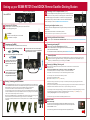
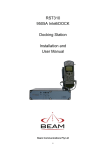
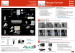
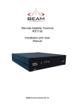
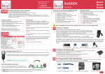
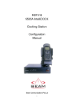
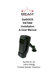
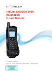
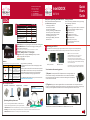
Beam Communications Pty Ltd 8 Anzed Court, Mulgrave Victoria, Australia, 3170 IntelliDOCK T: +61 3 8851 0400 F: +61 3 9560 9055 E: [email protected] W: www.beamcommunications.com SatDOCK Front of SatDOCK State Charge LED Mute LED (Off) Handset is fully charged (Solid) Handset is charging * (Solid) Charging Error (Solid) (Flashing - Slow) Handset absent (Solid) Mute Mode (Flashing - Slow) Privacy Mode Incompatible handset / (Flashing - Fast) Connection Error (Off) Normal Handsfree Mode USRQSG001602 LEDs RST310 Thank you for purchasing the BEAM RST310 Package Contents This QuickStart Guide lists the steps to install your BEAM Satellite equipment: Before commencing installation ensure your package has the following components: 1. Mounting your RST310 2. Connect AC / DC Power 3. Connecting your SatDOCK 4. Docking / Undocking your 9505A handset 5. Connecting an RJ11 telephone handset 6. Installing your external Iridium antenna 7. Connecting your Laptop / PC 8. Powering Up & Making / Receive calls 9. Mute Function RST310 *Eg. Unsafe ambient temperature for charging Front of RST310 Power LED: flashes during self-diagnosis then illuminates a steady green. Vmail/SMS LEDs: flashes to indicate message(s) are waiting in your voice mailbox to be retrieved. * This service is subject to network support and not available from all providers. Call LED: Varies with status of call, which can be: “In Call”, “Waiting to connect”, or “Incoming call” Signal LED: indicates strength of Iridium signal at your location. RED= no signal/PIN code required ORANGE= low signal GREEN = Good signal 1 RST310 Signal LED Flashing Red LED Flashing Red LED Constant LED Handset tone Distinctive dial tone: two tones of equal length Distinctive dial tone: high tone is longer than low tone Action required Enter four digit SIM PIN and await a change of tone (up to 10 seconds), then hang up. When successful the phone will register and proceed with normal use Enter the PUK code, await a change of tone (up to ten seconds) and hang up. When successful the phone will register and proceed with normal use Normal dial tone No action required If any problems, try the following: 1. Repeat these instructions to ensure everything has been completed. 2. Is there power to the unit? Check all connections and fuses. 3. Is the SIM card active? If not, refer to your Service Provider 4. If the antenna signal is not strong try moving antenna location to achieve better coverage/signal and re-test. For additional troubleshooting refer to your manual or visit us: www.beamcommunications.com RST310 options include: POTS Handset 910 Iridium Helix 1 x RST310 unit 1 x universal plug-pack power adapter, 110-240V AC 1 x 9-pin-to-9-pin RS-232 cable (Male to Female) 1 x Printed user manual 1 x SatDOCK Cradle 1 x SatDOCK Interface Cable 1 x RAM Bracket / 2 x M4 Screws 2 x Mounting Brackets 1 x Mounting Screws (packet) 1 x “Installing Iridium Antennas” Guide 1 x Beam Starter CD Mounting your RST310 The RST310 comes with two (2) right angle brackets that allow mounting for mobile and fixed positioning. Carefully slide the RST310 between the two mounting brackets and secure with the retaining screws. Note: To ensure a secure installation: 1. Mount the RST310 on a clean, even surface. 2. Clean the mount surface of the RST310. 3. Use the correct type of screws (as supplied) 4. If mounting on wood, ensure wood is structurally sound. 5. Leave enough room around the RST310 to allow easy access to the rear panel. PIN Code To make and receive calls, you may need to enter a PIN code. Quick Start Guide A: Drop-in mount B: Flush mount Do not install the unit in a permanently concealed area. Access must be possible in the event of future service. Your handset cradle mounting options: 1) Separate: Carefully slot the RST310 between the two mounting brackets and secure with the retaining screws. Mount the Ram-mount cradle for the 9505A in the desired location ensuring that there is sufficient cable length for the handset to connect to the main terminal. 2) Together: Using the brackets supplied the Ram-mount handset holder can be firmly attached to the Intelligent Handset Fax Adapter More info @ www.beamcommunications.com terminal as pictured below, follow the above instructions for mounting the terminal, however using the longer mounting screws supplied affix the additional ram-mount holding bracket to the side of the unit. Optimising Iridium performance Iridium is a line-of-sight Satellite network, conditions that can compromise the quality of the service you may receive include: 1. 2. 3. 1 & 2: Connect bracket to RST310 3 & 4: Secure RAM-mount on top of unit. 1. Obstructions: Provide the best satellite view for your antenna by removing all obstructions where possible 2. Cabling: Use the shortest cable length and the fewest number of connectors on all Iridium certified antenna cable runs 3. RF Interference: Install antenna as far away from other transmitters as possible. 4. Setting up your BEAM RST310 IntelliDOCK Remote Satellite Docking Station Handset Line iHandset COMM port 5 Connect a telephone handset, answering machine or cordless phone into the Line or Accessory socket. This socket supports a standard RJ11 plug. Facsimile Messaging via a standard RJ11 connection is not supported on the Iridium Network see your Service Provider to discuss the dedicated FX2600 Iridium Fax Adapter or visit us at www.beamcommunications.com Rear of RST310 SatDOCK 2 A. LOG port Connect the AC/DC Power Connecting an Intelligent handset (optional) With LIVE power turned OFF, connect power jack to rear of RST310. Secure cable by tightening collar ! 3 Power Connect to the Iridium Intelligent Handset, if supplied, directly to the Handset socket of the RST310. Only use the extension cables for this handset provided. CAUTION: DO NOT connect LIVE power to the unit until the installation is complete. Cables up to 30 metres in length are available from your Service Provider. 6 7 Connecting your SatDOCK To connect your SatDOCK to the IntelliDOCK, follow the below steps. Locate the supplied SMA / TNC Antenna Adapter. E. Connect the other end of the interface cable to the Interface port on the rear of the IntelliDOCK. Tighten both screws to secure. B. Fasten the Antenna Adapter to the Antenna cable. ! To Antenna the Antenna cable to the C. Connect SMA socket on the rear of the SatDOCK Cradle and screw to tighten. 8 the SatDOCK interface D. Connect cable to theinterface port on the rear of the SatDOCK Cradle and tighten both thumb screws. 4 Connecting an RJ11 telephone handset (optional) Installing your External Iridium Antenna See the specific “Iridium Antenna Installation Guide” manual or visit us @ www.beamcommunications.com Connecting your Laptop/PC Plug the serial cable into the Comm Port of the RST310. For more information on how to configure and access data services, please refer to the Beam Data Guide. For information on Iridium’s Data Services, please visit www.iridium.com Antenna Operation Please note that earlier firmware versions of the 9505A handset may display a message prompting the user to rotate the antenna. To toggle between enabling / disabling this Antenna Alert when in the SatDOCK, using the keypad on your 9505A handset, type in the following code : *#92# Powering Up & Making/Receiving calls When all previous 1-6 steps have been completed, confirm that the antenna is connected and the power loom active. Ensure that the 9505A handset is powered off and seated in the SatDOCK cradle. The handset will power on automatically once power is connected to the RST310. Once power is connected, allow up to 3 mins for the LEDs to register with network. To successfully make a call on the Iridium network, you need: 1) Dial tone on the telephone handset 2) Call LED must shine green or orange continuously. Docking / Undocking your 9505A handset th To dock the 9505A handset, firstly ensure you remove the rotating antenna from the handset. Place theied wi dset pl an Antenna Cable base of the 9505A handset into the seat of the SatDOCK ensuring that the pins on the bottom of the Sup 05A H 9505A handset line up with that on the seat of the SatDOCK cradle as illustrated below. 95 Push down on the handset to seat the handset base firmly in the SatDOCK cradle. To clip the handset into place, press and hold the button on top of the 9505A handset whilst pushing it back into the SatDOCK until it clips into place. Release the button on top. Gently pull on the handset to confirm that it is docked correctly and won’t come loose. When removing 9505A Handset from the SatDOCK cradle, reverse the above steps, ensuring you hold down the button on top of the handset before trying to remove it from the SatDOCK. The handset can now be powered on for normal mobile operation - refer to 9505A manual for further information. Continue to make your phone call as you normally use a traditional phone, noting any dialling prefix instructions advised by your service provider. Once you have entered the phone number you will hear progress pips from the Iridium network. It can take up to 30 seconds for the Iridium network to connect a call, so a pause at this stage is not unusual. You will shortly hear the called party end ringing, or hear a busy tone and voice message indicating why your call was not possible. When the other party answers the Call LED will change from steady orange to flashing orange, indicating 'call in progress'. This is a normal operating procedure. To end the call, hang up the handset. The Call LED light will then turn off. 9 Mute Function Mute Functionality To mute all audio to the handset whilst docked to the SatDOCK cradle, simply press the mute button once. A red light will illuminate on the mute button to visually confirm that the SatDOCK is muted. To un-mute, simply press the mute button again, and the mute light will extinguish. Stage 1 Stage 2 Stage 3 Stage 4 Stage 5