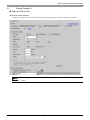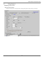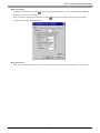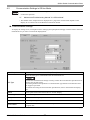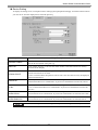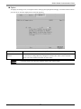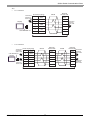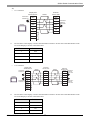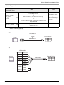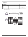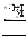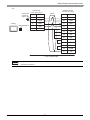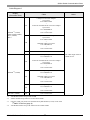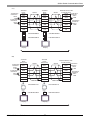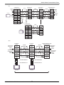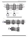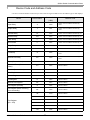
1
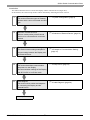
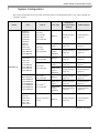
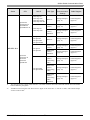
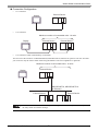
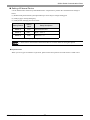
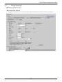
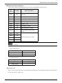
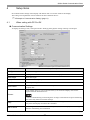
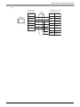
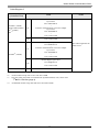
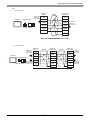
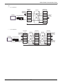
Mitsubishi Electric Corporation Q/QnA Serial Communication Driver 1 System Configuration....................................................................................................... 3 2 Selection of External Device .......................................................................................... 10 3 Example of Communication Setting ............................................................................... 11 4 Setup Items .................................................................................................................... 32 5 Cable Diagram ............................................................................................................... 39 6 Range of Supported Device Address............................................................................. 60 7 Device Code and Address Code.................................................................................... 64 8 Error Messages.............................................................................................................. 65 1 Q/QnA Serial Communication Driver Introduction This manual describes how to connect the Display and the External Device (target PLC). In this manual, the connection procedure will be described by following the below sections: 1 System Configuration This section shows the types of External Devices which can be connected and SIO type. )"1 System Configuration" (page 3) 2 Selection of External Device Select a model (series) of the External Device to be connected and connection method. )"2 Selection of External Device" (page 10) 3 Example of Communication Settings This section shows setting examples for communicating between the Display and the External Device. )"3 Example of Communication Setting" 4 Setup Items This section describes communication setup items on the Display. Set communication settings of the Display with GP-Pro EX or in off-line mode. )"4 Setup Items" (page 32) 5 Cable Diagram This section shows cables and adapters for connecting the Display and the External Device. )"5 Cable Diagram" (page 39) Operation GP-Pro EX Device/PLC Connection Manual 2 (page 11) Q/QnA Serial Communication Driver 1 System Configuration The system configuration in the case when the External Device of Mitsubishi Electric Corp. and the Display are connected is shown. Series CPU Q02CPU Q02HCPU Q06HCPU Q12HCPU Q25HCPU Q00JCPU Q00CPU Q01CPU Q02UCPU Q03UDCPU Q04UDHCPU Q06UDHCPU MELSEC Q Q00UJCPU Q00UCPU Q01UCPU Q10UDHCPU Q13UDHCPU Q20UDHCPU Q26UDHCPU Q03UDECPU Q04UDEHCPU Q06UDEHCPU Q10UDEHCPU Q13UDEHCPU Q20UDEHCPU Q26UDEHCPU Q00CPU Q01CPU Q00UJCPU Q00UCPU Q01UCPU Q02UCPU*2 Link I/F Example of Communication Settings Cable Diagram RS232C Setting Example 3 (page 17) Cable Diagram 1 (page 39) RS422/485 (4wire) Setting Example 4 (page 20) Cable Diagram 2 (page 41) RS422/485 (4wire) Multilink Setting Example 6 (page 26) Cable Diagram 6 (page 55) RS232C Setting Example 3 (page 17) Cable Diagram 1 (page 39) RS422/485 (4wire) Setting Example 4 (page 20) Cable Diagram 2 (page 41) RS422/485 (4wire) Multilink Setting Example 6 (page 26) Cable Diagram 6 (page 55) RS232C Setting Example 3 (page 17) Cable Diagram 1 (page 39) RS422/485 (4wire) Setting Example 4 (page 20) Cable Diagram 2 (page 41) RS422/485 (4wire) Multilink Setting Example 6 (page 26) Cable Diagram 6 (page 55) RS232C Setting Example 5 (page 23) Cable Diagram 3 (page 47) SIO Type QJ71C24 QJ71C24-R2 QJ71C24N QJ71C24N-R2 QJ71C24 QJ71C24N QJ71C24N-R4 QJ71C24N QJ71C24N-R2 QJ71C24N QJ71C24N-R4 QJ71C24N*1 QJ71C24N-R2*1 QJ71C24N*1 QJ71C24N-R4*1 RS232C connector on CPU continued to next page GP-Pro EX Device/PLC Connection Manual 3 Q/QnA Serial Communication Driver Series CPU Q2ASCPU Q2ASCPU-S1 Q2ASHCPU Q2ASHCPU-S1 Link I/F A1SJ71QC24 A1SJ71QC24N A1SJ71QC24-R2 A1SJ71QC24N-R2 A1SJ71QC24 A1SJ71QC24N AJ71QC24 AJ71QC24N AJ71QC24-R2 AJ71QC24N-R2 AJ71QC24 AJ71QC24N MELSEC QnA Example of Communication Settings Cable Diagram RS232C Setting Example 1 (page 11) Cable Diagram 1 (page 39) RS422/485 (4wire) Setting Example 2 (page 14) Cable Diagram 2 (page 41) RS422/485 (4wire) Multilink Setting Example 7 (page 29) Cable Diagram 6 (page 55) RS232C Setting Example 1 (page 11) Cable Diagram 4 (page 48) RS422/485 (4wire) Setting Example 2 (page 14) Cable Diagram 2 (page 41) RS422/485 (4wire) Multilink Setting Example 7 (page 29) Cable Diagram 6 (page 55) RS422/485 (4wire) (when using CH1) Setting Example 2 (page 14) Cable Diagram 5 (page 50) RS422/485 (4wire) (when using CH2) Setting Example 2 (page 14) Cable Diagram 2 (page 41) RS422/485 (4wire) (when using CH2) Multilink Setting Example 7 (page 29) Cable Diagram 6 (page 55) SIO Type Q2ACPU Q2ACPU-S1 Q3ACPU Q4ACPU Q4ARCPU AJ71QC24-R4 AJ71QC24N-R4 *1 The unit whose first 5 digits of the serial No. is less than "10042" cannot be connected with the universal model built-in Ethernet port QCPU. *2 Available when using the unit whose first 5 digits of the serial No. is "10102" or later, and GX Developer version 8.76E or later. GP-Pro EX Device/PLC Connection Manual 4 Q/QnA Serial Communication Driver Connection Configuration • 1:1 Connection External Device Display • 1:n Connection Maximum number of connectable units : 16 units External Device Display • External Device 1:n Connection (when communicating via network) You can access other stations via MELSECNET/H, MELSECNET/10, Ethernet or Q Series C24 unit. Note that you can access only the source station when using the RS232C connector on Q00CPU or Q01CPU. Maximum number of connectable units : 16 units Display External Device (MELSECNET/H, MELSECNET/10 or Ethernet) External Device External Device • In case of communication via network,please set larger value than the response monitoring time of the relay station for timeout setteings. GP-Pro EX Device/PLC Connection Manual 5 Q/QnA Serial Communication Driver Setting examples for access beyond the network are shown below. Check the details of the setup items in "Setup Item." )"4 Setup Items" (page 32) External Device1 Display (Station No.5) Network No.1 (MELSECNET/H) External Device11 External Device12 Network No.2 (MELSECNET/10) (PC No.6) External Device22 External Device21 (PC No.8) Serial Communication (I/O No.32) (Station No.15) External Device to be Port No. Station No. Network No. PC No. Request Request destination destination module module I/O No. Station No. Accessed External Device 1 1025 5 0 255 1023 0 External Device 11 1026 5 1 6 1023 0 External Device 22 1027 5 2 8 32 15 GP-Pro EX Device/PLC Connection Manual 6 Q/QnA Serial Communication Driver • n:1 Connection (Multilink connection) Maximum number of connectable units: 16 units Display Display Display External Device • The maximum number of connectable Displays is 16 units. However, keeping performance in consideration, the number of Displays that can be substantially used is up to 4. • n:m Connection (Multilink connection) Maximum number of connectable units: 16 units Display Display Display External Device External Device Maximum number of connectable units: 16 units per Display • The maximum number of connectable Displays is 16 units. However, keeping performance in consideration, the number of Displays that can be substantially used is up to 4. GP-Pro EX Device/PLC Connection Manual 7 Q/QnA Serial Communication Driver IPC COM Port When connecting IPC with an External Device, the COM port used depends on the series and SIO type. Please refer to the IPC manual for details. Usable port Usable Port Series RS-232C RS-422/485(4 wire) RS-422/485(2 wire) *1 PS-2000B COM1 , COM2, COM3*1, COM4 - - PS-3450A, PS-3451A, PS3000-BA, PS3001-BD COM1, COM2*1*2 COM2*1*2 COM2*1*2 PS-3650A, PS-3651A COM1*1 - - PS-3700A (Pentium®4-M) PS-3710A COM1*1, COM2*1, COM3*2 , COM4 COM3*2 COM3*2 PS-3711A COM1*1, COM2*2 COM2*2 COM2*2 PL-3000B, PL-3600T, PL-3600K, PL-3700T, PL-3700K, PL-3900T COM1*1*2, COM2*1, COM3, COM4 COM1*1*2 COM1*1*2 *1 The RI/5V can be switched. Use the IPC’s switch to change if necessary. *2 Set up the SIO type with the DIP switch. Please set up as follows according to SIO type to be used. DIP switch setting: RS-232C DIP switch 1 Setting *1 OFF Description Reserved (always OFF) 2 OFF 3 OFF 4 OFF Output mode of SD (TXD) data: Always output 5 OFF Terminal resistance (220Ω) insertion to SD (TXD): None 6 OFF Terminal resistance (220Ω) insertion to RD (RXD): None 7 OFF Short-circuit of SDA (TXA) and RDA (RXA): Not available 8 OFF Short-circuit of SDB (TXB) and RDB (RXB): Not available 9 OFF 10 OFF SIO type: RS-232C RS (RTS) Auto control mode: Disabled *1 When using PS-3450A, PS-3451A, PS3000-BA and PS3001-BD, turn ON the set value. GP-Pro EX Device/PLC Connection Manual 8 Q/QnA Serial Communication Driver DIP switch setting: RS-422/485 (4 wire) DIP switch Setting Description 1 OFF 2 ON 3 ON 4 OFF Output mode of SD (TXD) data: Always output 5 OFF Terminal resistance (220Ω) insertion to SD (TXD): None 6 OFF Terminal resistance (220Ω) insertion to RD (RXD): None 7 OFF Short-circuit of SDA (TXA) and RDA (RXA): Not available 8 OFF Short-circuit of SDB (TXB) and RDB (RXB): Not available Reserved (always OFF) SIO type: RS-422/485 *1 *1 9 OFF 10 OFF*1 RS (RTS) Auto control mode: Disabled When the connection configuration are the n:1 and n:m connections (both Multilink connections), turn ON the set value. DIP switch setting: RS-422/485 (2 wire) DIP switch Setting Description 1 OFF 2 ON 3 ON 4 OFF Output mode of SD (TXD) data: Always output 5 OFF Terminal resistance (220Ω) insertion to SD (TXD): None 6 OFF Terminal resistance (220Ω) insertion to RD (RXD): None 7 ON Short-circuit of SDA (TXA) and RDA (RXA): Available 8 ON Short-circuit of SDB (TXB) and RDB (RXB): Available 9 ON 10 ON Reserved (always OFF) SIO type: RS-422/485 RS (RTS) Auto control mode: Enabled GP-Pro EX Device/PLC Connection Manual 9 Q/QnA Serial Communication Driver 2 Selection of External Device Select the External Device to be connected to the Display. Setup Items Setup Description Number of Devices/ PLCs Enter an integer from 1 to 4 for the number of series to set. Manufacturer Select the manufacturer of the External Device to be connected. Select "Mitsubishi Electric Corporation". Series Select a model (series) of the External Device to be connected and connection method. Select "Q/QnA Serial Communication". Check the External Device which can be connected in "Q/QnA Serial Communication" in system configuration. "1 System Configuration" (page 3) ) Port Select the Display port to be connected to the External Device. Use System Area Check this option to synchronize the system data area of the Display and the device (memory) of the External Device. When synchronized, you can use the ladder program of the External Device to switch the display or display the window on the Display. Cf. GP-Pro EX Reference Manual "Appendix 1.4 LS Area (Direct Access Method)" This can be also set with GP-Pro EX or in the Display's off-line mode. Cf. GP-Pro EX Reference Manual "5.17.6 [System Settings] Setting Guide, [Display Unit] Settings Guide, System Area Settings" Cf. Maintenance/Troubleshooting Manual "2.15.1 Settings common to all Display models, [Main Unit Settings] Settings Guide, System Area Settings" GP-Pro EX Device/PLC Connection Manual 10 Q/QnA Serial Communication Driver 3 Example of Communication Setting Examples of communication settings of the Display and the External Device, recommended by Pro-face, are shown. 3.1 Setting Example 1 Setting of GP-Pro EX Communication Settings To display the setting screen, select [Device/PLC Settings ] from [System setting window] in workspace. • When using A1SJ71QC24N, A1SJ71QC24N-R2, AJ71QC24N or AJ71QC24N-R2, you can set the "Speed" up to 115200. GP-Pro EX Device/PLC Connection Manual 11 Q/QnA Serial Communication Driver Device Setting To display the setting screen, click ([Setting]) of External Device you want to set from [Device-Specific Settings] of [Device/PLC Settings]. When you connect multiple External Device, click from [Device-Specific Settings] of [Device/PLC Settings] to add another External Device. Important Item When you use 2 types of interface in A1SJ71QC24N, A1SJ71QC24N-R2, AJ71QC24N or AJ71QC24N-R2, please set the total speed of CH1 and CH2 to 115200 or less. GP-Pro EX Device/PLC Connection Manual 12 Q/QnA Serial Communication Driver Setting of External Device Use the front switch of the computer link unit to set the communication settings as below. DIP Switch Settings SW1 OFF Operation Setting = Independent Operation SW2 ON Data Length = 8 bits SW3 ON With/Without Parity = With SW4 OFF Parity = Odd parity SW5 OFF Stop Bit = 1 bit SW6 ON Sum Check = Enable SW7 ON Write during RUN = Enable SW8 ON Setting change Enable/Disable = Enable SW9 OFF SW10 ON SW11 ON SW12 OFF Setup Description Transmission Speed = 19200 • When using A1SJ71QC24N, A1SJ71QC24N-R2, AJ71QC24N or AJ71QC24N-R2, you can set the "Speed" up to 115200. • • *1 Station Setting Switch Setting Switch Settings x 10 0 x1 0 Mode Setting Switch Setting Switch Settings MODE (CH1) 5*1 MODE (CH2) 5*1 Set the value according to [Format] to be used. Important Item When you use 2 types of interface in A1SJ71QC24N, A1SJ71QC24N-R2, AJ71QC24N or AJ71QC24N-R2, please set the total speed of CH1 and CH2 to 115200 or less. GP-Pro EX Device/PLC Connection Manual 13 Q/QnA Serial Communication Driver 3.2 Setting Example 2 Setting of GP-Pro EX Communication Settings To display the setting screen, select [Device/PLC Settings] from [System setting window] in workspace. • When using A1SJ71QC24N, AJ71QC24N or AJ71QC24N-R4, you can set the "Speed" up to 115200. GP-Pro EX Device/PLC Connection Manual 14 Q/QnA Serial Communication Driver Device Setting To display the setting screen, click ([Setting]) of External Device you want to set from [Device-Specific Settings] of [Device/PLC Settings]. When you connect multiple External Device, click from [Device-Specific Settings] of [Device/PLC Settings] to add another External Device. Important Item When you use 2 types of interface in A1SJ71QC24N, AJ71QC24N or AJ71QC24N-R4, please set the total speed of CH1 and CH2 to 115200 or less. GP-Pro EX Device/PLC Connection Manual 15 Q/QnA Serial Communication Driver Setting of External Device Use the front switch of the computer link unit to set the communication settings as below. DIP Switch Settings SW1 OFF Operation Setting = Independent Operation SW2 ON Data Length = 8 bits SW3 ON With/Without Parity = With SW4 OFF Parity = Odd parity SW5 OFF Stop Bit = 1 bit SW6 ON Sum Check = Enable SW7 ON Write during RUN = Enable SW8 ON Setting change Enable/Disable = Enable SW9 OFF SW10 ON SW11 ON SW12 OFF Setup Description Transmission Speed = 19200 • When using A1SJ71QC24N, AJ71QC24N or AJ71QC24N-R4, you can set the "Speed" up to 115200. • • *1 Station Setting Switch Setting Switch Settings x 10 0 x1 0 Mode Setting Switch Setting Switch Settings MODE (CH1) 5*1 MODE (CH2) 5*1 Set the value according to [Format] to be used. Important Item When you use 2 types of interface in A1SJ71QC24N, AJ71QC24N or AJ71QC24N-R4, please set the total speed of CH1 and CH2 to 115200 or less. GP-Pro EX Device/PLC Connection Manual 16 Q/QnA Serial Communication Driver 3.3 Setting Example 3 Setting of GP-Pro EX Communication Settings To display the setting screen, select [Device/PLC Settings] from [System setting window] in workspace. GP-Pro EX Device/PLC Connection Manual 17 Q/QnA Serial Communication Driver Device Setting To display the setting screen, click ([Setting]) of External Device you want to set from [Device-Specific Settings] of [Device/PLC Settings]. When you connect multiple External Device, click from [Device-Specific Settings] of [Device/PLC Settings] to add another External Device. Important Item When you use 2 types of interface in QJ71C24 or QJ71C24-R2, please set the total speed of CH1 and CH2 to 115200 or less. GP-Pro EX Device/PLC Connection Manual 18 Q/QnA Serial Communication Driver Setting of External Device Use the GPP function software by Mitsubishi Electric Corporation to perform the communication settings as below. (1) Double-click [PC Parameter] from [Parameter] to select the [I/O Assign Setting] tab. (2) Click [Type] to select [Intelligent]. (3) Click [Switch Settings] and set as below. Setting Switch Setting Value Switch 1 07E6 Switch 2 0005*1 Mode = Form 5 Switch 5 0000 Station No. = 0 *1 Setup Description 19200/8/With/Odd/1 Set the value according to [Format] to be used. • Please refer to the manual of the External Device for more detail on setting description. Important Item When you use 2 types of interface in QJ71C24 or QJ71C24-R2, please set the total speed of CH1 and CH2 to 115200 or less. GP-Pro EX Device/PLC Connection Manual 19 Q/QnA Serial Communication Driver 3.4 Setting Example 4 Setting of GP-Pro EX Communication Settings To display the setting screen, select [Device/PLC Settings] from [System setting window] in workspace. GP-Pro EX Device/PLC Connection Manual 20 Q/QnA Serial Communication Driver Device Setting To display the setting screen, click ([Setting]) of External Device you want to set from [Device-Specific Settings] of [Device/PLC Settings]. When you connect multiple External Device, click from [Device-Specific Settings] of [Device/PLC Settings] to add another External Device. Important Item When you use 2 types of interface in QJ71C24, please set the total speed of CH1 and CH2 to 115200 or less. GP-Pro EX Device/PLC Connection Manual 21 Q/QnA Serial Communication Driver Setting of External Device Use the GPP function software by Mitsubishi Electric Corporation to perform the communication settings as below. (1) Double-click [PC Parameter] from [Parameter] to select the [I/O Assign Setting] tab. (2) Click [Type] to select [Intelligent]. (3) Click [Switch Settings] and set as below. Setting Switch Setting Value Switch 3 07E6 Switch 4 0005*1 Mode = Form 5 Switch 5 0000 Station No. = 0 *1 Setup Description 19200/8/With/Odd/1 Set the value according to [Format] to be used. • Please refer to the manual of the External Device for more detail on setting description. Important Item When you use 2 types of interface in QJ71C24, please set the total speed of CH1 and CH2 to 115200 or less. GP-Pro EX Device/PLC Connection Manual 22 Q/QnA Serial Communication Driver 3.5 Setting Example 5 Setting of GP-Pro EX Communication Settings To display the setting screen, select [Device/PLC Settings] from [System setting window] in workspace. GP-Pro EX Device/PLC Connection Manual 23 Q/QnA Serial Communication Driver Device Setting To display the setting screen, click ([Setting]) of External Device you want to set from [Device-Specific Settings] of [Device/PLC Settings]. When you connect multiple External Device, click from [Device-Specific Settings] of [Device/PLC Settings] to add another External Device. GP-Pro EX Device/PLC Connection Manual 24 Q/QnA Serial Communication Driver Setting of External Device Use the GPP function software by Mitsubishi Electric Corporation to perform the communication settings as below. (1) Double-click [PC Parameter] from [Parameter] to select [Serial Communication Settings]. (2) Set as below. *1 Setup Items Settings Use Serial Communication Function*1 Use Baud Rate 19.2Kbps Sum Check Enable Transmission Wait Time No Wait Write Setting during RUN Enable Check the checkbox to make other setting items become available to set. GP-Pro EX Device/PLC Connection Manual 25 Q/QnA Serial Communication Driver 3.6 Setting Example 6 Setting of GP-Pro EX Communication Settings To display the setting screen, select [Device/PLC Settings] from [System setting window] in workspace. • When simultaneously using GP2000 Series during multilink connection, select "QnA Comp. 3C Frame: Format 4" from the "Format". GP-Pro EX Device/PLC Connection Manual 26 Q/QnA Serial Communication Driver Device Setting To display the setting screen, click ([Setting]) of External Device you want to set from [Device-Specific Settings] of [Device/PLC Settings]. When you connect multiple External Device, click from [Device-Specific Settings] of [Device/PLC Settings] to add another External Device. Important Item When you use 2 types of interface in QJ71C24, please set the total speed of CH1 and CH2 to 115200 or less. GP-Pro EX Device/PLC Connection Manual 27 Q/QnA Serial Communication Driver Setting of External Device Use the GPP function software by Mitsubishi Electric Corporation to perform the communication settings as below. (1) Double-click [PC Parameter] from [Parameter] to select the [I/O Assign Setting] tab. (2) Click [Type] to select [Intelligent]. (3) Click [Switch Settings] and set as below. Setting Switch Setting Value Switch 3 07E6 Switch 4 0005*1 Mode = Form 5 Switch 5 0000 Station No. = 0 *1 Setup Description 19200/8/With/Odd/1 Set the value according to [Format] to be used. • Please refer to the manual of the External Device for more detail on setting description. Important Item When you use 2 types of interface in QJ71C24, please set the total speed of CH1 and CH2 to 115200 or less. GP-Pro EX Device/PLC Connection Manual 28 Q/QnA Serial Communication Driver 3.7 Setting Example 7 Setting of GP-Pro EX Communication Settings To display the setting screen, select [Device/PLC Settings] from [System setting window] in workspace. • When using A1SJ71QC24N, AJ71QC24N or AJ71QC24N-R4, you can set the "Speed" up to 115200. • When simultaneously using GP2000 Series during multilink connection, select "QnA Comp. 3C Frame: Format 4" from the "Format". GP-Pro EX Device/PLC Connection Manual 29 Q/QnA Serial Communication Driver Device Setting To display the setting screen, click ([Setting]) of External Device you want to set from [Device-Specific Settings] of [Device/PLC Settings]. When you connect multiple External Device, click from [Device-Specific Settings] of [Device/PLC Settings] to add another External Device. Important Item When you use 2 types of interface in A1SJ71QC24N, AJ71QC24N or AJ71QC24N-R4, please set the total speed of CH1 and CH2 to 115200 or less. GP-Pro EX Device/PLC Connection Manual 30 Q/QnA Serial Communication Driver Setting of External Device Use the front switch of the computer link unit to set the communication settings as below. DIP Switch Settings SW1 OFF Operation Setting = Independent Operation SW2 ON Data Length = 8 bits SW3 ON With/Without Parity = With SW4 OFF Parity = Odd parity SW5 OFF Stop Bit = 1 bit SW6 ON Sum Check = Enable SW7 ON Write during RUN = Enable SW8 ON Setting change Enable/Disable = Enable SW9 OFF SW10 ON SW11 ON SW12 OFF Setup Description Transmission Speed = 19200 • When using A1SJ71QC24N, AJ71QC24N or AJ71QC24N-R4, you can set the "Speed" up to 115200. • • *1 Station Setting Switch Setting Switch Settings x 10 0 x1 0 Mode Setting Switch Setting Switch Settings MODE (CH1) 5*1 MODE (CH2) 5*1 Set the value according to [Format] to be used. Important Item When you use 2 types of interface in A1SJ71QC24N, AJ71QC24N or AJ71QC24N-R4, please set the total speed of CH1 and CH2 to 115200 or less. GP-Pro EX Device/PLC Connection Manual 31 Q/QnA Serial Communication Driver 4 Setup Items Set communication settings of the Display with GP-Pro EX or in off-line mode of the Display. The setting of each parameter must be identical to that of External Device. )"3 Example of Communication Setting" (page 11) 4.1 When setting with GP-Pro EX Communication Settings To display the setting screen, select [Device/PLC Settings] from [System setting window] in workspace. Setup Items Setup Description SIO Type Select the SIO type to communicate with the External Device. Speed Select speed between the External Device and the Display. Data Length Select data length. Parity Select how to check parity. Stop Bit Select stop bit length. Flow Control Select the communication control method to prevent overflow of transmission and reception data. Use an integer from 1 to 127 to enter the time (s) for which the Display waits for the response from the External Device. Timeout In case of communicating via network,please set larger value than the response monitoring time of the relay station for timeout settings. Retry In case of no response from the External Device, use an integer from 0 to 255 to enter how many times the Display retransmits the command. Wait To Send Use an integer from 0 to 255 to enter standby time (ms) for the Display from receiving packets to transmitting next commands. continued to next page GP-Pro EX Device/PLC Connection Manual 32 Q/QnA Serial Communication Driver Setup Items Setup Description Select the communication frame for the use of MELSEC communication protocol, from "QnA Comp. 3C Frame: Format 4" or "QnA Comp. 4C Frame: Format 5". Format When simultaneously using GP2000 Series during multilink connection, select "QnA Comp. 3C Frame: Format 4" RI/VCC You can switch RI/VCC of the 9th pin when you select RS232C for SIO type. It is necessary to change RI/5V by changeover switch of IPC when connect with IPC. Please refer to the manual of the IPC for more detail. GP-Pro EX Device/PLC Connection Manual 33 Q/QnA Serial Communication Driver Device Setting To display the setting screen, click ([Setting]) of External Device you want to set from [Device-Specific Settings] of [Device/PLC Settings]. When [Allowable No. of Device/PLCs] is multiple, click from [Device-Specific Settings] of [Device/PLC Settings] to add another External Device. Setup Items Setup Description Station No. Use an integer from 0 to 31 to enter the station number of the External Device directly connected to the Display. Connected to Q Series C24 I/F Module Check this checkbox only when the Q Series C24 I/F unit is used. If this is checked when the Q Series C24 I/F unit is not used, the error may be displayed on the External Device. Network No. Set when you communicate via network. Use an integer from 0 to 239 to enter network No. of the External Device to communicate. If you do not communicate via network, enter 0. PC No. Set when you communicate via network. Use an integer from 0 to 64 or 125 to 126 to enter PC No. of the External Device to communicate. If you do not communicate via network, enter 255. Request destination module I/O No. Set when you communicate via network. Use an integer from 0 to 511 to enter I/O No. of the External Device to communicate. If you do not communicate via network, enter 1023. Request destination module Station No. Set when you communicate via network. Use an integer from 0 to 31 to enter station No. of the External Device to communicate. If you do not communicate via network, enter 0. GP-Pro EX Device/PLC Connection Manual 34 Q/QnA Serial Communication Driver 4.2 Communication Settings in Off-line Mode • Refer to the Maintenance/Troubleshooting manual for information on how to enter off-line mode or about the operation. Cf. Maintenance/Troubleshooting Manual "2.2 Off-line Mode" • The number of the setup items to be displayed for 1 page in the off-line mode depends on the Display in use. Please refer to the Reference manual for details. Communication Settings To display the setting screen, touch [Device/PLC Settings] from [Peripheral Settings] in off-line mode. Touch the External Device you want to set from the displayed list. Setup Items Setup Description Select the SIO type to communicate with the External Device. SIO Type To make the communication settings correctly, confirm the serial interface specifications of Display unit for [SIO Type]. We cannot guarantee the operation if a communication type that the serial interface does not support is specified. For details concerning the serial interface specifications, refer to the manual for Display unit. Speed Select speed between the External Device and the Display. Data Length Select data length. Parity Select how to check parity. Stop Bit Select stop bit length. Flow Control Select the communication control method to prevent overflow of transmission and reception data. continued to next page GP-Pro EX Device/PLC Connection Manual 35 Q/QnA Serial Communication Driver Setup Items Setup Description Use an integer from 1 to 127 to enter the time (sec) for which the Display waits for the response from the External Device. Timeout In case of communicating via network,please set larger value than the response monitoring time of the relay station for timeout settings. Retry In case of no response from the External Device, use an integer from 0 to 255 to enter how many times the Display retransmits the command. Wait To Send Use an integer from 0 to 255 to enter standby time (ms) for the Display from receiving packets to transmitting next commands. Select the communication frame for the use of MELSEC communication protocol, from "QnA Comp. 3C Frame: Format 4" or "QnA Comp. 4C Frame: Format 5". Format When simultaneously using GP2000 Series during multilink connection, select "QnA Comp. 3C Frame: Format 4" GP-Pro EX Device/PLC Connection Manual 36 Q/QnA Serial Communication Driver Device Setting To display the setting screen, touch [Device/PLC Settings] from [Peripheral Settings]. Touch the External Device you want to set from the displayed list, and touch [Device]. Setup Items Setup Description Device/PLC Name Select the External Device for device setting. Device name is a title of External Device set with GP-Pro EX.(Initial value [PLC1]) Station No. Use an integer from 0 to 31 to enter the station number of the External Device directly connected to the Display. Q Series C24 I/F Select “ON” and “OFF” respectively when the Q Series C24 I/F unit is used and when the Q Series C24 I/F unit is not used. If “ON” is selected when the Q Series C24 I/F unit is not used, the error may be displayed on the External Device. Network No. Set when you communicate via network. Use an integer from 0 to 239 to enter network No. of the External Device to communicate. If you do not communicate via network, enter 0. PC No. Set when you communicate via network. Use an integer from 0 to 64 or 125 to 126 to enter PC No. of the External Device to communicate. If you do not communicate via network, enter 255. Request destination module I/O No. Set when you communicate via network. Use an integer from 0 to 511 to enter I/O No. of the External Device to communicate. If you do not communicate via network, enter 1023. Request destination module Station No. Set when you communicate via network. Use an integer from 0 to 31 to enter station No. of the External Device to communicate. If you do not communicate via network, enter 0. • Do not set the duplicate device settings in multiple devices. Illegal address may be read. GP-Pro EX Device/PLC Connection Manual 37 Q/QnA Serial Communication Driver Option To display the setting screen, touch [Device/PLC Settings] from [Peripheral Settings]. Touch the External Device you want to set from the displayed list, and touch [Option]. Setup Items RI/VCC Setup Description You can switch RI/VCC of the 9th pin when you select RS232C for SIO type. It is necessary to change RI/5V by changeover switch of IPC when connect with IPC. Please refer to the manual of the IPC for more detail. • GP-4100 series do not have the [Option] setting in the off-line mode. GP-Pro EX Device/PLC Connection Manual 38 Q/QnA Serial Communication Driver 5 Cable Diagram The cable diagram shown below may be different from the cable diagram recommended by Mitsubishi Electric Corp. Please be assured there is no operational problem in applying the cable diagram shown in this manual. • The FG pin of the External Device body must be D-class grounded. Please refer to the manual of the External • SG and FG are connected inside the Display. When connecting SG to the External Device, design the system Device for more details. not to form short-circuit loop. • Connect the isolation unit, when communication is not stabilized under the influence of a noise etc.. Cable Diagram 1 Display (Connection Port) GP3000 (COM1) ST (COM1) IPC*1 PC/AT GP-4105 (COM1) *1 Cable Notes 1A Mitsubishi Q link cable by Pro-face CA3-CBLLNKMQ-01 1B User-created cable 1C User-created cable The cable length must be 15m or less. Only the COM port which can communicate by RS-232C can be used. IPC COM Port (page 8) ) 1A) CA3-CBLLNKMQ-01 Display External Device 1B) Display side D-sub 9 pin (socket) Display Shield External Device side D-sub 9 pin (plug) Pin Signal name Pin Signal name 2 RD(RXD) 3 SD(TXD) 3 SD(TXD) 2 RD(RDX) 4 ER(DTR) 6 DSR(DR) 5 SG 5 SG 7 RS(RTS) 1 CD 8 CS(CTS) 4 DTR(ER) 8 CS(CTS) Shell FG GP-Pro EX Device/PLC Connection Manual 39 Q/QnA Serial Communication Driver 1C) Display side Terminal block Display Shield External Device side D-sub 9 pin (plug) Signal name Pin Signal name RD(RXD) 3 SD(TXD) SD(TXD) 2 RD(RDX) ER(DTR) 6 DSR(DR) SG 5 SG RS(RTS) 1 CD CS(CTS) 4 DTR(ER) 8 CS(CTS) Shell FG GP-Pro EX Device/PLC Connection Manual 40 Q/QnA Serial Communication Driver Cable Diagram 2 Display (Connection Port) GP3000*1 (COM1) AGP-3302B (COM2) ST*2 (COM2) IPC*3 Cable 2A COM port conversion adapter by Pro-face CA3-ADPCOM-01 + Connector terminal block conversion adapter by Pro-face CA3-ADPTRM-01 + User-created cable 2B User-created cable 2C Online adapter by Pro-face CA4-ADPONL-01 + Connector terminal block conversion adapter by Pro-face CA3-ADPTRM-01 + User-created cable 2D Online adapter by Pro-face CA4-ADPONL-01 + User-created cable 2E User-created cable GP3000*4 (COM2) GP-4106 (COM1) *1 All GP3000 models except AGP-3302B *2 All ST models except AST-3211A and AST-3302B *3 Only the COM port which can communicate by RS-422/485 (4 wire) can be used. IPC COM Port (page 8) *4 All GP3000 models except GP-3200 series and AGP-3302B ) GP-Pro EX Device/PLC Connection Manual 41 Notes The cable length must be 500m or less. Q/QnA Serial Communication Driver 2A) • 1:1 Connection Sdqlhm`k aknbj Chrok`x B@2,@COBNL,/0 Sdqlhm`shnm qdrhrs`mbd 22/Ω0.3V B@2,@COSQL,/0 Dwsdqm`k Cduhbdrhcd Rghdkc Rhfm`k m`ld Rhfm`k m`ld QC@ RC@ QCA RCA RC@ QC@ RCA QCA RF RF Sdqlhm`shnm qdrhrs`mbd 22/Ω0.3V EF Trdq,bqd`sdcb`akd • 1:n Connection Sdqlhm`shnm qdrhrs`mbd 22/Ω0.3V Chrok`x B@2,@COBNL,/0 B@2,@COSQL,/0 Sdqlhm`shnm qdrhrs`mbd 22/Ω0.3V Sdqlhm`k aknbj Rghdkc Dwsdqm`k Cduhbdrhcd Rghdkc Dwsdqm`k Cduhbdrhcd Rhfm`k m`ld Rhfm`k m`ld Rhfm`k m`ld QC@ RC@ RC@ QCA RCA RCA RC@ QC@ QC@ RCA QCA QCA RF RF RF EF EF Trdq,bqd`sdcb`akd GP-Pro EX Device/PLC Connection Manual 42 Sdqlhm`shnm qdrhrs`mbd 22/Ω0.3V Sdqlhm`shnm qdrhrs`mbd 22/Ω0.3V Q/QnA Serial Communication Driver 2B) • 1:1 Connection Chrok`xrhcd C,rta8ohm'rnbjds( Sdqlhm`shnm qdrhrs`mbd 22/Ω0.3V Chrok`x • Rghdkc Dwsdqm`k Cduhbdrhcd Ohm Rhfm`k m`ld Rhfm`k m`ld 0 QC@ RC@ 1 QCA RCA 2 RC@ QC@ 6 RCA QCA 4 RF RF 3 DQ@ EF 7 BR@ 8 DQA 5 BRA Rgdkk EF Sdqlhm`shnm qdrhrs`mbd 22/Ω0.3V 1:n Connection Chrok`xrhcd C,rta8ohm'rnbjds( Sdqlhm`shnm qdrhrs`mbd 22/Ω0.3V Chrok`x Sdqlhm`shnm qdrhrs`mbd 22/Ω0.3V Rghdkc Dwsdqm`k Cduhbdrhcd Rghdkc Dwsdqm`k Cduhbdrhcd Ohm Rhfm`k m`ld Rhfm`k m`ld 0 QC@ RC@ 1 QCA RCA RCA 2 RC@ QC@ QC@ 6 RCA QCA QCA 4 RF RF RF 3 DQ@ EF EF 7 BR@ 8 DQA 5 BRA GP-Pro EX Device/PLC Connection Manual 43 Rhfm`k m`ld RC@ Sdqlhm`shnm qdrhrs`mbd 22/Ω0.3V Sdqlhm`shnm qdrhrs`mbd 22/Ω0.3V Q/QnA Serial Communication Driver 2C) • 1:1 Connection Sdqlhm`k aknbj Sdqlhm`shnm qdrhrs`mbd 22/Ω0.3V Chrok`x B@3,@CONMK,/0 B@2,@COSQL,/0 Rghdkc Rhfm`k m`ld Dwsdqm`k Cduhbdrhcd Rhfm`k m`ld QC@ RC@ QCA RCA RC@ QC@ RCA QCA RF RF Sdqlhm`shnm qdrhrs`mbd 22/Ω0.3V EF Trdq,bqd`sdcb`akd • 1:n Connection Sdqlhm`k aknbj Sdqlhm`shnm qdrhrs`mbd 22/Ω0.3V Chrok`x B@3,@CONMK,/0 Sdqlhm`shnm qdrhrs`mbd B@2,@COSQL,/0 22/Ω0.3V Rghdkc Dwsdqm`k Cduhbdrhcd Rghdkc Dwsdqm`k Cduhbdrhcd Rhfm`k m`ld Rhfm`k m`ld Rhfm`k m`ld QC@ RC@ RC@ QCA RCA RCA RC@ QC@ QC@ RCA QCA QCA RF RF RF EF EF Trdq,bqd`sdcb`akd GP-Pro EX Device/PLC Connection Manual 44 Sdqlhm`shnm qdrhrs`mbd 22/Ω0.3V Sdqlhm`shnm qdrhrs`mbd 22/Ω0.3V Q/QnA Serial Communication Driver 2D) • 1:1 Connection C,rta8ohm'oktf( Sdqlhm`shnm qdrhrs`mbd 22/Ω0.3V Dwsdqm`k Cduhbdrhcd Ohm Rhfm`k m`ld Rhfm`k m`ld 1 QC@ RC@ 6 QCA RCA 2 RC@ QC@ 7 RCA QCA 4 RF RF Rgdkk EF EF Chrok`x B@3,@CONMK,/0 Rghdkc Sdqlhm`shnm qdrhrs`mbd 22/Ω0.3V Trdq,bqd`sdcb`akd • 1:n Connection C,rta8ohm'oktf( Sdqlhm`shnm qdrhrs`mbd 22/Ω0.3V B@3,@CONMK,/0 Chrok`x Sdqlhm`shnm qdrhrs`mbd 22/Ω0.3V Rghdkc Dwsdqm`k Cduhbdrhcd Rhfm`k m`ld RC@ Rghdkc Dwsdqm`k Cduhbdrhcd Ohm Rhfm`k m`ld 1 QC@ 6 QCA RCA RCA 2 RC@ QC@ QC@ 7 RCA QCA QCA 4 RF RF RF Rgdkk EF EF EF Trdq,bqd`sdcb`akd GP-Pro EX Device/PLC Connection Manual 45 Rhfm`k m`ld RC@ Sdqlhm`shnm qdrhrs`mbd 22/Ω0.3V Sdqlhm`shnm qdrhrs`mbd 22/Ω0.3V Q/QnA Serial Communication Driver 2E) • 1:1 Connection Display side Terminal block Termination resistance*1 Display Shield External Device side Signal name Signal name RDA SDA RDB SDB SDA RDA SDB RDB SG SG ERA FG Termination resistance 330Ω 1/4W CSA ERB CSB *1 The resistance in the Display is used as the termination resistance. Set the value of the DIP Switch on the rear of the Display as shown in the table below. • DIP Switch No. Set Value 1 OFF 2 OFF 3 ON 4 OFF 1:n Connection Display side Terminal block Termination resistance*2 Display Termination resistance*2 Shield External Device side Signal name Signal name RDA SDA Shield External Device side Signal name SDA RDB SDB SDB SDA RDA RDA SDB RDB RDB SG SG SG ERA FG FG Termination resistance 330Ω 1/4W Termination resistance 330Ω 1/4W CSA ERB CSB *2 The resistance in the Display is used as the termination resistance. Set the value of the DIP Switch on the rear of the Display as shown in the table below. DIP Switch No. Set Value 1 ON 2 OFF 3 ON 4 OFF GP-Pro EX Device/PLC Connection Manual 46 Q/QnA Serial Communication Driver Cable Diagram 3 Display (Connection Port) Cable Notes GP3000 (COM1) ST (COM1) IPC*1 PC/AT 3A Mitsubishi Q connection cable by Pro-face CA3-CBLQ-01 (5m) or RS-232C cable by Mitsubishi Electric Corp. QC30R2 (3m) or RS-232C cable for QCPU connection by Diatrend Corp. DQCABR2V-H GP-4105 (COM1) 3B Mitsubishi PLC Q Series CPU I/F Cable by Pro-face ZC9CBQ31(3m) *1 Available to order the length of DQCABR2V-H by Diatrend Corp. up to 15m. Only the COM port which can communicate by RS-232C can be used. IPC COM Port (page 8) ) 3A) CA3-CBLQ-01 or QC30R2 or DQCABR2V-H Display External Device 3B) Display side Terminal block Signal name Cable color Display RD(RXD) Green SD(TXD) Brown ER(DTR) Yellow External Device SG ZC9CBQ31 Red Orange DR(DSR) Blue Blue CS(CTS) Blue GP-Pro EX Device/PLC Connection Manual 47 Q/QnA Serial Communication Driver Cable Diagram 4 Display (Connection Port) GP3000 (COM1) ST (COM1) IPC*1 PC/AT GP-4105 (COM1) *1 Cable Notes 4A RS-232C cable by Pro-face CA3-CBL232/5M-01 (5m) 4B User-created cable 4C User-created cable The cable length must be 15m or less. Only the COM port which can communicate by RS-232C can be used. IPC COM Port (page 8) ) 4A) Display External Device CA3-CBL232/5M-01 4B) Display side D-sub 9 pin (socket) Display External Device side D-sub 25 pin (plug) Shield Pin Signal name RD(RXD) 2 SD(TXD) 3 SD(TXD) 3 RD(RXD) 4 ER(DTR) 6 DSR(DR) 5 SG 7 SG 7 RS(RTS) 8 CD 8 CS(CTS) 20 DTR(ER) 5 CS(CTS) 1 FG Pin Signal name 2 GP-Pro EX Device/PLC Connection Manual 48 Q/QnA Serial Communication Driver 4C) External Device side D-sub 25 pin (plug) Display side Terminal block Display Shield Pin Signal name RD(RXD) 2 SD(TXD) SD(TXD) 3 RD(RXD) ER(DTR) 6 DSR(DR) SG 7 SG RS(RTS) 8 CD CS(CTS) 20 DTR(ER) 5 CS(CTS) 1 FG Signal name GP-Pro EX Device/PLC Connection Manual 49 Q/QnA Serial Communication Driver Cable Diagram 5 Display (Connection Port) GP3000*1 (COM1) AGP-3302B (COM2) ST*2 (COM2) IPC*3 Cable 5A COM port conversion adapter by Pro-face CA3-ADPCOM-01 + Connector terminal block conversion adapter by Pro-face CA3-ADPTRM-01 + User-created cable 5B User-created cable 5C Online adapter by Pro-face CA4-ADPONL-01 + Connector terminal block conversion adapter by Pro-face CA3-ADPTRM-01 + User-created cable 5D Online adapter by Pro-face CA4-ADPONL-01 + User-created cable 5E User-created cable GP3000*4 (COM2) GP-4106 (COM1) *1 All GP3000 models except AGP-3302B *2 All ST models except AST-3211A and AST-3302B *3 Only the COM port which can communicate by RS-422/485 (4 wire) can be used. IPC COM Port (page 8) *4 All GP3000 models except GP-3200 series and AGP-3302B ) GP-Pro EX Device/PLC Connection Manual 50 Notes The cable length must be 500m or less. Q/QnA Serial Communication Driver 5A) Sdqlhm`shnm qdrhrs`mbd 22/Ω0.3V Dwsdqm`kCduhbdrhcd C,rta14ohm'oktf( Sdqlhm`k aknbj Chrok`x B@2,@COBNL,/0 B@2,@COSQL,/0 Rghdkc Rhfm`k m`ld Ohm Rhfm`k m`ld QC@ 2 RC@ QCA 05 RCA RC@ 1 QC@ RCA 04 QCA RF 6 RF RF 7 RF 1/ RF 10 RF 3 CRQ@ 4 CSQ@ 06 CRQA 07 CSQA 0 EF Trdq,bqd`sdcb`akd • As the External Device has the termination resistance built-in, you do not need to connect the termination resistance. 5B) Chrok`xrhcd C,rta8ohm'rnbjds( Sdqlhm`shnm qdrhrs`mbd 22/Ω0.3V Chrok`x Dwsdqm`kCduhbdrhcd C,rta14ohm'oktf( Rghdkc Ohm Rhfm`k m`ld QC@ 2 RC@ 1 QCA 05 RCA 2 RC@ 1 QC@ 6 RCA 04 QCA 4 RF 6 RF 3 DQ@ 7 RF 7 BR@ 1/ RF 8 DQA 10 RF 5 BRA 3 CRQ@ 4 CSQ@ 06 CRQA 07 CSQA 0 EF Ohm Rhfm`k m`ld 0 • As the External Device has the termination resistance built-in, you do not need to connect the termination resistance. GP-Pro EX Device/PLC Connection Manual 51 Q/QnA Serial Communication Driver 5C) Dwsdqm`kCduhbdrhcd C,rta14ohm'oktf( Sdqlhm`k aknbj Sdqlhm`shnm qdrhrs`mbd Rhfm`km`ld 22/Ω0.3V Rghdkc Ohm Rhfm`k m`ld QC@ 2 RC@ QCA 05 RCA RC@ 1 QC@ RCA 04 QCA RF 6 RF RF 7 RF 1/ RF 10 RF 3 CRQ@ 4 CSQ@ 06 CRQA 07 CSQA 0 EF Chrok`x B@3,@COBNL,/0 B@2,@COSQL,/0 Trdq,bqd`sdcb`akd • As the External Device has the termination resistance built-in, you do not need to connect the termination resistance. GP-Pro EX Device/PLC Connection Manual 52 Q/QnA Serial Communication Driver 5D) External Device D-sub 25 pin (plug) Display side D-sub 9 pin (plug) Termination resistance 330Ω 1/4W Display CA4-ADPONL-01 Pin Signl name 2 Shield Pin Signl name RDA 3 SDA 7 RDB 16 SDB 3 SDA 2 RDA 8 SDB 15 RDB 5 SG 7 SG 8 SG 20 SG 21 SG 4 DSRA 5 DTRA 17 DSRB 18 DTRB 1 FG User-created cable • As the External Device has the termination resistance built-in, you do not need to connect the termination resistance. GP-Pro EX Device/PLC Connection Manual 53 Q/QnA Serial Communication Driver 5E) External Device side D-sub 25 pin (plug) Display side Terminal block Termination resistance*1 Display Shield Pin Signal name RDA 3 SDA RDB 16 SDB SDA 2 RDA SDB 15 RDB SG 7 SG ERA 8 SG CSA 20 SG ERB 21 SG CSB 4 DSRA 5 DTRA Signal name 17 DSRB 18 DTRB 1 FG • As the External Device has the termination resistance built-in, you do not need to connect the termination resistance. *1 The resistance in the Display is used as the termination resistance. Set the value of the DIP Switch on the rear of the Display as shown in the table below. DIP Switch No. Set Value 1 OFF 2 OFF 3 ON 4 OFF GP-Pro EX Device/PLC Connection Manual 54 Q/QnA Serial Communication Driver Cable Diagram 6 Display (Connection Port) Cable 6A COM port conversion adapter by Pro-face CA3-ADPCOM-01 + Connector terminal block conversion adapter by Pro-face CA3-ADPTRM-01 + User-created cable 6B COM port conversion adapter by Pro-face CA3-ADPCOM-01 + Multilink cable by Pro-face CA3-CBLMLT-01 + User-created cable 6C User-created cable 6D Online adapter by Pro-face CA4-ADPONL-01 + Connector terminal block conversion adapter by Pro-face CA3-ADPTRM-01 + User-created cable 6E Online adapter by Pro-face CA4-ADPONL-01 + Multilink cable by Pro-face CA3-CBLMLT-01 + User-created cable 6F Online adapter by Pro-face CA4-ADPONL-01 + User-created cable 6G User-created cable GP3000*1 (COM1) AGP-3302B (COM2) ST*2 (COM2) IPC*3 GP3000*4 (COM2) GP-4106 (COM1) *1 All GP3000 models except AGP-3302B *2 All ST models except AST-3211A and AST-3302B *3 Only the COM port which can communicate by RS-422/485 (4 wire) can be used. IPC COM Port (page 8) *4 All GP3000 models except GP-3200 series and AGP-3302B ) GP-Pro EX Device/PLC Connection Manual 55 Notes The cable length must be 1200m or less. Q/QnA Serial Communication Driver 6A) Terminal block Termination resistance 330 Ω 1/4W Termination resistance 330 Ω 1/4W Terminal block Shield External Device side Terminal block Termination Signal resistance name 330 Ω SDA 1/4W Shield Signal name Signal name RDA RDA RDB RDB SDB SDA SDA RDA SDB SDB RDB SG SG SG TRM FG FG CA3-ADPTRM-01 CA3-ADPTRM-01 CA3-ADPCOM-01 CA3-ADPCOM-01 Display Termination resistance 330 Ω 1/4W Display User-created cable 6B) Sdqlhm`k aknbj 'L2rbqdv( Sdqlhm`shnm qdrhrs`mbd 22/ Ω 0.3V Sdqlhm`shnm qdrhrs`mbd 22/ Ω 0.3V Rhfm`k m`ld Sdqlhm`k aknbj 'L2rbqdv( Rghdkc Rghdkc Rhfm`k m`ld Dwsdqm`kCduhbdrhcd Sdqlhm`kaknbj Sdqlhm`shnm Rhfm`k qdrhrs`mbd m`ld 22/ Ω RC@ 0.3V QC@ QC@ QCA QCA RCA RC@ RC@ QC@ RCA RCA QCA RF RF RF EF EF EF B@2,BAKLKS,/0 B@2,BAKLKS,/0 B@2,@COBNL,/0 B@2,@COBNL,/0 Chrok`x Chrok`x Trdq,bqd`sdcb`akd GP-Pro EX Device/PLC Connection Manual 56 Sdqlhm`shnm qdrhrs`mbd 22/ Ω 0.3V Q/QnA Serial Communication Driver 6C) Sdqlhm`k qdrhrs`mbd 22/ Ω 0.3V Chrok`xrhcd C,rta8ohm'rnbjds( Chrok`x Sdqlhm`k qdrhrs`mbd 22/ Ω 0.3V Sdqlhm`kaknbj 'L2rbqdv( Rghdkc Rghdkc Sdqlhm`kaknbj 'L2rbqdv( Rghdkc Dwsdqm`kCduhbdrhcd Sdqlhm`kaknbj Sdqlhm`k Ohm Rhfm`km`ld Rhfm`km`ld Rhfm`km`ld 0 QC@ QC@ QC@ 1 QCA QCA QCA 2 RC@ RC@ RC@ QC@ Rhfm`km`ld qdrhrs`mbd 22/ Ω RC@ 0.3V RCA 6 RCA RCA RCA QCA 4 RF RF RF RF 3 DQ@ EF EF EF 7 BR@ 8 DQA 5 BRA Rgdkk EF Chrok`xrhcd C,rta8ohm'rnbjds( Chrok`x Sdqlhm`k qdrhrs`mbd 22/ Ω 0.3V Rghdkc Ohm Rhfm`km`ld Rhfm`km`ld 0 QC@ QC@ 1 QCA QCA 2 RC@ RC@ 6 RCA RCA 4 RF RF 3 DQ@ EF 7 BR@ 8 DQA 5 BRA 6D) Terminal block Termination resistance 330 Ω 1/4W Termination resistance 330 Ω 1/4W Signal name Terminal block Shield Shield Signal name External Device side Terminal block Termination Signal resistance name 330 Ω SDA 1/4W RDA RDA RDB RDB SDB SDA SDA RDA SDB SDB RDB SG SG SG TRM FG FG CA3-ADPTRM-01 CA3-ADPTRM-01 CA4-ADPONL-01 CA3-ADPONL-01 Display Display User-created cable GP-Pro EX Device/PLC Connection Manual 57 Termination resistance 330 Ω 1/4W Q/QnA Serial Communication Driver 6E) Sdqlhm`k aknbj 'L2rbqdv( Sdqlhm`shnm qdrhrs`mbd 22/ Ω 0.3V Sdqlhm`shnm qdrhrs`mbd 22/ Ω 0.3V Sdqlhm`k aknbj 'L2rbqdv( Rghdkc Rhfm`k m`ld Rghdkc Rhfm`k m`ld Dwsdqm`kCduhbdrhcd Sdqlhm`kaknbj Sdqlhm`shnm Rhfm`k qdrhrs`mbd m`ld 22/ Ω RC@ 0.3V QC@ QC@ QCA QCA RCA RC@ RC@ QC@ RCA RCA QCA RF RF RF EF EF EF B@2,BAKLKS,/0 B@2,BAKLKS,/0 B@3,@CONMK,/0 B@3,@CONMK,/0 Chrok`x Sdqlhm`shnm qdrhrs`mbd 22/ Ω 0.3V Chrok`x Trdq,bqd`sdcb`akd 6F) Chrok`x Sdqlhm`k qdrhrs`mbd 22/ Ω 0.3V Sdqlhm`k B@3,@CONMK,/0 qdrhrs`mbd 22/ Ω 0.3V C,rta8ohm'oktf( Sdqlhm`kaknbj 'L2rbqdv( Rghdkc Rghdkc Sdqlhm`kaknbj 'L2rbqdv( Rghdkc Dwsdqm`kCduhbdrhcd Sdqlhm`kaknbj Sdqlhm`k Ohm Rhfm`km`ld Rhfm`km`ld Rhfm`km`ld 1 QC@ QC@ QC@ 6 QCA QCA QCA 2 RC@ RC@ RC@ QC@ Rhfm`km`ld qdrhrs`mbd 22/ Ω RC@ 0.3V RCA 7 RCA RCA RCA QCA 4 RF RF RF RF Rgdkk EF EF EF EF C,rta8ohm'oktf( Chrok`x B@3,@CONMK,/0 Rghdkc Ohm Rhfm`km`ld Rhfm`km`ld 1 QC@ QC@ 6 QCA QCA 2 RC@ RC@ 7 RCA RCA 4 RF RF EF GP-Pro EX Device/PLC Connection Manual 58 Sdqlhm`k qdrhrs`mbd 22/ Ω 0.3V Q/QnA Serial Communication Driver 6G) Display side Terminal block Terminal resistance*1 Terminal resistance*1 *1 Shield Display side Terminal block Shield External Device side Terminal block Terminal Signal name Signal name RDA RDA RDB RDB SDA SDA RDA SDB SDB RDB SG SG SG ERA ERA FG CSA CSA ERB ERB CSB CSB Display Display Signal name resistance 330 Ω SDA 1/4W SDB Terminal resistance 330 Ω 1/4W The resistance in the Display is used as the termination resistance. Set the value of the DIP Switch on the rear of the Display as shown in the table below. DIP Switch No. Set Value 1 ON 2 OFF 3 ON 4 OFF For the Displays other than that used as the terminal, set the DIP Switch 1-4 on the rear of the Display to OFF in the n:1 connection. GP-Pro EX Device/PLC Connection Manual 59 Q/QnA Serial Communication Driver 6 Range of Supported Device Address Range of supported device address is shown in the table below. Please note that the actually supported range of the devices varies depending on the External Device to be used. Please check the actual range in the manual of your External Device. MELSEC Q (High performance model, Basic model) / MELSEC QnA Series This address can be specified as system data area. Device Bit Address Word Address Input Relay X0000-X1FFF X0000-X1FF0 Output Relay Y0000-Y1FFF Y0000-Y1FF0 Internal Relay M00000-M32767 M00000-M32752 Special Relay SM0000-SM2047 SM0000-SM2032 Latch Relay L00000-L32767 L00000-L32752 Annunciator F00000-F32767 F00000-F32752 Edge Relay V00000-V32767 V00000-V32752 Step Relay S0000-S8191 S0000-S8176 Link Relay B0000-B7FFF B0000-B7FF0 Special Link Relay SB000 - SB7FF SB000 - SB7F0 Timer (Contact) TS00000-TS23087 - Timer (Coil) TC00000-TC23087 - Retentive Timer (Contact) SS00000-SS23087 - Retentive Timer (Coil) SC00000-SC23087 - Counter (Contact) CS00000-CS23087 - Counter (Coil) CC00000-CC23087 - Timer (Current Value) - TN00000-TN23087 Retentive Timer (Current Value) - SN00000-SN23087 Counter (Current Value) - CN00000-CN23087 Data Register - D00000-D25983 Special Register - SD0000-SD2047 Link Register - W0000-W657F Special Link Register - SW000-SW7FF File Register (Normal) - R00000-R32767 *1 File Register (Block switching is not necessary) - ZR0000000-ZR1042431 *1 GP-Pro EX Device/PLC Connection Manual 60 32bits Notes Q/QnA Serial Communication Driver Device File Register (0R - 31R) *2 Bit Address Word Address - 0R0000-0R32767 - 1R0000-1R32767 - 2R0000-2R32767 : : - 30R0000-30R32767 - 31R0000-31R26623 32bits Notes *1 *1 It is different by the memory card which uses the range of file register. *2 Set the block No. on the head of device name. This is the device name for conversion with GP-Pro/PB III for Windows. When you newly specify the device, we recommend that you should use the file register (Block switching is not necessary). • Please refer to the GP-Pro EX Reference Manual for system data area. Cf. GP-Pro EX Reference Manual "Appendix 1.4 LS Area (Direct Access Method)" • Please refer to the precautions on manual notation for icons in the table. ) "Manual Symbols and Terminology" GP-Pro EX Device/PLC Connection Manual 61 Q/QnA Serial Communication Driver MELSEC Q (Universal model) Series This address can be specified as system data area. Device First 5 digits of the serial No. in the CPU unit: Less than 10042 First 5 digits of the serial No. in the CPU unit: 10042 or later Bit Address Word Address Bit Address Word Address Input Relay X0000-X1FFF X0000-X1FF0 X0000-X1FFF X0000-X1FF0 Output Relay Y0000-Y1FFF Y0000-Y1FF0 Y0000-Y1FFF Y0000-Y1FF0 Internal Relay M00000M32767 M00000M32752 M00000M61439 M00000M61424 Special Relay SM0000SM2047 SM0000SM2032 SM0000SM2047 SM0000SM2032 Latch Relay L00000L32767 L00000L32752 L00000L32767 L00000L32752 Annunciator F00000F32767 F00000F32752 F00000F32767 F00000F32752 Edge Relay V00000V32767 V00000V32752 V00000V32767 V00000V32752 Step Relay S0000-S8191 S0000-S8176 S0000-S8191 S0000-S8176 Link Relay B0000-B7FFF B0000-B7FF0 B0000-BEFFF B0000-BEFF0 Special Link Relay SB0000 SB7FFF SB0000 SB7FF0 SB0000 SB7FFF SB0000 SB7FF0 Timer (Contact) TS00000TS25023 - TS00000TS25471 - Timer (Coil) TC00000TC25023 - TC00000TC25471 - Retentive Timer (Contact) SS00000SS25023 - SS00000SS25471 - Retentive Timer (Coil) SC00000SC25023 - SC00000SC25471 - Counter (Contact) CS00000CS25023 - CS00000CS25471 - Counter (Coil) CC00000CC25023 - CC00000CC25471 - Timer (Current Value) - TN00000TN25023 - TN00000TN25471 32bits Notes continued to next page GP-Pro EX Device/PLC Connection Manual 62 Q/QnA Serial Communication Driver First 5 digits of the serial No. in the CPU unit: Less than 10042 Device First 5 digits of the serial No. in the CPU unit: 10042 or later 32bits Notes Bit Address Word Address Bit Address Word Address Retentive Timer (Current Value) - SN00000SN25023 - SN00000SN25471 Counter (Current Value) - CN00000CN25023 - CN00000CN25471 Data Register - D00000D28159 - D0000000D0065535 Special Register - SD0000SD2047 - SD0000SD2047 Link Register - W0000W6DEF - W000000W00FFFF Special Link Register - SW0000SW6DFF - SW0000SW6FFF File Register (Normal) - R00000R32767 - R00000R32767 *1 File Register (Block switching is not necessary) - ZR0000000ZR4184063 - ZR0000000ZR4184063 *1 - 0R00000R32767 - 0R00000R32767 - 1R00001R32767 - 1R00001R32767 - 2R00002R32767 - 2R00002R32767 : : : : - 30R000030R32767 - 30R000030R32767 - 31R000031R26623 - 31R000031R26623 File Register (0R - 31R) *2 *1 *1 It is different by the memory card which uses the range of file register. *2 Set the block No. on the head of device name. This is the device name for conversion with GP-Pro/PB III for Windows. When you newly specify the device, we recommend that you should use the file register (Block switching is not necessary). • Please refer to the GP-Pro EX Reference Manual for system data area. Cf. GP-Pro EX Reference Manual "Appendix 1.4 LS Area (Direct Access Method)" • Please refer to the precautions on manual notation for icons in the table. ) "Manual Symbols and Terminology" GP-Pro EX Device/PLC Connection Manual 63 Q/QnA Serial Communication Driver 7 Device Code and Address Code Use device code and address code when you select "Device Type & Address" for the address type in data displays. Device Name Device Code (HEX) Input Relay X 0080 Value of word address divided by 0x10 Output Relay Y 0081 Value of word address divided by 0x10 Internal Relay M 0082 Value of word address divided by 16 Special Relay SM 0083 Value of word address divided by 16 Latch Relay L 0084 Value of word address divided by 16 Annunciator F 0085 Value of word address divided by 16 Edge Relay V 0086 Value of word address divided by 16 Step Relay S 0087 Value of word address divided by 16 Link Relay B 0088 Value of word address divided by 0x10 Special Link Relay SB 0089 Value of word address divided by 0x10 Timer (Current Value) TN 0060 Word Address Retentive Timer (Current Value) SN 0062 Word Address Counter (Current Value) CN 0061 Word Address Data Register D 0000 Word Address Special Register SD 0001 Word Address Link Register W 0002 Word Address Special Link Register SW 0003 Word Address File Register (Normal) R 000F Word Address ZR 000E Word Address 0R 0010 Word Address 1R 0011 Word Address 2R 0012 Word Address : : 30R 002E Word Address 31R 002F Word Address Device File Register (Block switching is not necessary) File Register (0R - 31R) GP-Pro EX Device/PLC Connection Manual 64 Address Code : Q/QnA Serial Communication Driver 8 Error Messages Error messages are displayed on the Display screen as follows: "No.: Device Name: Error Message (Error Occurrence Area)". Each description is shown below. Item Description No. Error No. Device Name Name of the External Device where error occurs. Device name is a title of the External Device set with GP-Pro EX. (Initial value [PLC1]) Error Message Displays messages related to the error which occurs. Displays IP address or device address of the External Device where error occurs, or error codes received from the External Device. Error Occurrence Area • IP address is displayed such as "IP address(Decimal): MAC address( Hex)". • Device address is diplayed such as "Address: Device address". • Received error codes are displayed such as "Decimal[Hex]". Display Examples of Error Messages "RHAA035: PLC1: Error has been responded for device write command (Error Code: 2 [02H])" • Refer to your External Device manual for details on received error codes. • Refer to "When an error is displayed (Error Code List)" in "Maintenance/Troubleshooting Manual" for details on the error messages common to the driver. GP-Pro EX Device/PLC Connection Manual 65 Q/QnA Serial Communication Driver GP-Pro EX Device/PLC Connection Manual 66