1
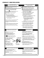
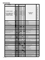
Model and Manufacturing
numbers listed on pages
4 - 14.
Service
Instructions
40" 80% and 90% Gas Furnaces & Accessories
GUIA, GCIA, GUIB, GCIB, GUIC, GCIC, GUID,
GUIS, GCIS, GUIV, GUCA, GCCA, GUVA, GUSA
DESIGN
CE RT I F I E D
CE
This manual replaces RS6600001 Rev. 0 April 2000.
R TIFIE D
REV. 1 - New models added to manual.
Heating&Air Conditioning
®
This manual is to be used by qualified HVAC technicians only. Amana
does not assume any responsibility for property damage or personal injury
due to improper service procedures performed by an unqualified person.
RS6600001
Revision 1
October 2000
INDEX
Important Safety Information ................................................................................... 2-3
Product Identification ................................................................................................ 4-20
Accessories ............................................................................................................. 21-32
Product Design ........................................................................................................ 33-74
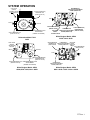
System Operation .................................................................................................... 75-117
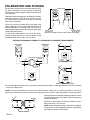
Polarization and Phasing ......................................................................................... 118
Maintenance ............................................................................................................ 119-121
Servicing .................................................................................................................. 122-146
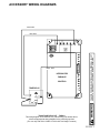
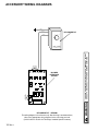
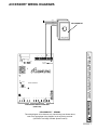
Accessory Wiring Diagrams .................................................................................... 147-153
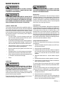
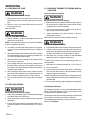
IMPORTANT INFORMATION
Pride and workmanship go into every product to provide our customers with quality products. It is possible, however,
that during its lifetime a product may require service. Products should be serviced only by a qualified service technician
who is familiar with the safety procedures required in the repair and who is equipped with the proper tools, parts, testing
instruments and the appropriate service manual. REVIEW ALL SERVICE INFORMATION IN THE APPROPRIATE
SERVICE MANUAL BEFORE BEGINNING REPAIRS.
IMPORTANT NOTICES FOR CONSUMERS AND SERVICERS
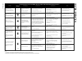
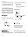
RECOGNIZE SAFETY SYMBOLS, WORDS AND LABELS
DANGER
DANGER - Immediate hazards which WILL result in
severe personal injury or death.
WARNING
WARNING - Hazards or unsafe practices which COULD
result in severe personal injury or death.
CAUTION
CAUTION - Hazards or unsafe practices which COULD
result in minor personal injury or product or property damage.
2 Rev. 1
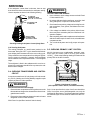
IMPORTANT INFORMATION
WARNING
IF REPAIRS ARE ATTEMPTED BY UNQUALIFIED PERSONS, DANGEROUS CONDITIONS (SUCH AS EXPOSURE TO ELECTRICAL SHOCK)
MAY RESULT. THIS MAY CAUSE SERIOUS INJURY OR DEATH.
AMANA WILL NOT BE RESPONSIBLE FOR ANY INJURY OR PROPERTY
CAUTION DAMAGE ARISING FROM IMPROPER SERVICE OR SERVICE PROCEDURES. IF YOU PERFORM SERVICE ON YOUR OWN PRODUCT, YOU
ASSUME RESPONSIBILITY FOR ANY PERSONAL INJURY OR PROPERTY DAMAGE WHICH
MAY RESULT.
To locate an authorized servicer, please consult your telephone book or the dealer from whom you purchased this
product. For further assistance, please contact:
CONSUMER AFFAIRS DEPT.
AMANA HEATING & AIR CONDITIONING
FAYETTEVILLE, TN 37334
OR
CALL
1-877-254-4729
and ask for
Consumer Affairs
3 Rev. 1
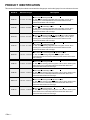
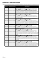
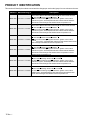
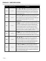
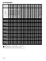
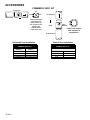
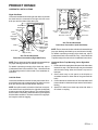
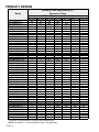
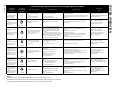
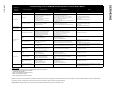
PRODUCT IDENTIFICATION
This section will identify the models covered and the changes per each model group from one release to the next.
Model #
Manufacturing #
GUIA***A**
P1177301F- P1177308F
GUIA***B**
P1206601F- P1206608F
GUIA***CA**
P1207201F- P1207208F
GCIA***A**
P1177401F- P1177408F
GCIA***CX**
P1207301F - P1207308F
GUIB***A**
P1186401F- P1186408F
GUIB***B**
P1206801F - P1206807F
GUIB***CX**
P1207701F - P1207707F
GCIB***A**
P1186501F - P1186508F
4 Rev. 1
Description
Gas Furnace Upflow/Horizontal Induced Draft A Air Command 80 SSE
Furnace "A" Initial Design Series.
40" 80% furnace featuring integrated electronic ignition control, silicon
carbide ignitor, electrodepositioned textured steel cabinet and 409
stainless steel tubular heat exchanger.
Gas Furnace Upflow/Horizontal Induced Draft A Air Command 80 SSE
Furnace "B" Second Design Series.
40" 80% furnace featuring integrated electronic ignition control, silicon
carbide ignitor, electrodepositioned textured steel cabinet and 409
stainless steel tubular heat exchanger.
Gas Furnace Upflow/Horizontal Induced Draft A Air Command 80 SSE
Furnace "C" Third Design Series "A" Standard Unit (not NOx certified).
40" 80% furnace featuring integrated electronic ignition control, silicon
carbide ignitor, electrodepositioned textured steel cabinet and 409
stainless steel tubular heat exchanger.
Gas Furnace Counterflow/Horizontal Induced Draft A Air Command 80
SSE Furnace "A" Initial Design Series.
40" 80% furnace featuring integrated electronic ignition control, silicon
carbide ignitor, electrodepositioned textured steel cabinet and 409
stainless steel tubular heat exchanger.
Gas Furnace Counterflow/Horizontal Induced Draft A Air Command 80
SSE Furnace "C" Third Design Series "X" NOx Certified.
40" 80% furnace featuring integrated electronic ignition control,
electrodepositioned textured steel cabinet and 409 stainless steel tubular
heat exchanger.
Gas Furnace Upflow/Horizontal Induced Draft B Air Command 80 SV
Furnace "A" Initial Design Series.
40" 80% furnace featuring electronic ignition control, silicon carbide ignitor,
radiant flame sensor, electrodepositioned textured steel cabinet and
aluminized steel tubular heat exchanger.
Gas Furnace Upflow/Horizontal Induced Draft B Air Command 80 SV
Furnace "B" Second Design Series.
40" 80% furnace featuring electronic ignition control, silicon carbide ignitor,
radiant flame sensor, electrodepositioned textured steel cabinet and
aluminized steel tubular heat exchanger.
Gas Furnace Upflow/Horizontal Induced Draft B Air Command 80 SV
Furnace "C" Third Design Series "X" NOx Certified.
40" 80% furnace featuring electronic ignition control, silicon carbide ignitor,
radiant flame sensor, electrodepositioned textured steel cabinet and
aluminized steel tubular heat exchanger.
Gas Furnace Counterflow/Horizontal Induced Draft B Air Command 80 SV
Furnace "A" Initial Design Series.
40" 80% furnace featuring electronic ignition control, silicon carbide ignitor,
radiant flame sensor, electrodepositioned textured steel cabinet and
aluminized steel tubular heat exchanger.
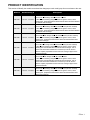
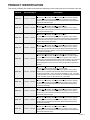
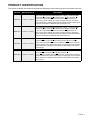
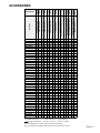
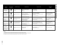
PRODUCT IDENTIFICATION
This section will identify the models covered and the changes per each model group from one release to the next.
Model #
Manufacturing #
GUIC***CX**
P1207401F - P1207408F
GUIC***CA**
P1207601F - P1207608F
GUIC***DA**
P1222501F - P1222508F
GUIC***DA**
P1226601F - P1226608F
GUIC***DX**
P1226701F - P1226708F
GUIC***CA**
P1229001F - P1229008F
Description
Gas Furnace Upflow/Horizontal Induced Draft C Air Command 80 SSE
Furnace "C" Third Design Series "X" NOx Certified.
40" 80% furnace featuring integrated electronic ignition control, silicon
carbide ignitor, electrodepositioned textured steel cabinet and 409 stainless
steel tubular heat exchanger.
Gas Furnace Upflow/Horizontal Induced Draft C Air Command 80 SSE
Furnace "C" Third Design Series "A" Standard Unit (not NOx certified).
40" 80% furnace featuring integrated electronic ignition control, silicon
carbide ignitor, electrodepositioned textured steel cabinet and 409 stainless
steel tubular heat exchanger.
Gas Furnace Upflow/Horizontal Induced Draft C Air Command 80 SSE
Furnace "D" Fourth Design Series "A" Standard Unit (not NOx certified).
40" 80% furnace featuring integrated electronic ignition control, silicon
carbide ignitor, prepainted textured steel cabinet and 409 stainless steel
tubular heat exchanger.
Gas Furnace Upflow/Horizontal Induced Draft C Air Command 80 SSE
Furnace D Fourth Design Series "A" Standard Unit (not NOx certified).
40" 80% furnace featuring integrated electronic ignition control, silicon
carbide ignitor and 409 stainless steel tubular heat exchanger. Use of
smooth cold rolled steel substrate and a smooth top coat for furnace
cabinet to replace prepainted furnaces until new coating is approved for
prepainted material.
Gas Furnace Upflow/Horizontal Induced Draft C Air Command 80 SSE
Furnace "D" Fourth Design Series "X" NOx Certified.
40" 80% furnace featuring integrated electronic ignition control, silicon
carbide ignitor and 409 stainless steel tubular heat exchanger. Use of
smooth cold rolled steel substrate and a smooth top coat for furnace
cabinet to replace prepainted furnaces until new coating is approved for
prepainted material.
Gas Furnace Upflow/Horizontal Induced Draft C Air Command 80 SSE
Furnace "C" Third Design Series "A" Standard Unit (not NOx certified).
40" 80% furnace featuring integrated electronic ignition control, silicon
carbide ignitor, prepainted textured steel cabinet and 409 stainless steel
tubular heat exchanger.
5 Rev. 1
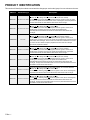
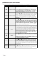
PRODUCT IDENTIFICATION
This section will identify the models covered and the changes per each model group from one release to the next.
Model #
Manufacturing #
GUIC***CA**
Gas Furnace Upflow/Horizontal Induced Draft C Air Command 80 SSE
Furnace "C" Third Design Series "A" Standard Unit (not NOx certified).
40" 80% furnace featuring integrated electronic ignition control, silicon
P1229101F - P1229108F
carbide ignitor, electrodepositioned textured steel cabinet, 409 stainless
steel tubular heat exchanger. Change from embossed bottom knock-out to
perforated bottom knock-out and addition of internal side filter retention.
GUIC***CX**
Gas Furnace Upflow/Horizontal Induced Draft C Air Command 80 SSE
Furnace "C" Third Design Series "X" NOx Certified.
P1229201F - P1229208F 40" 80% furnace featuring integrated electronic ignition control, silicon
carbide ignitor, prepainted textured steel cabinet and 409 stainless steel
tubular heat exchanger.
GUIC***CX**
Gas Furnace Upflow/Horizontal Induced Draft C Air Command 80 SSE
Furnace "C" Third Design Series "X" NOx Certified.
40" 80% furnace featuring integrated electronic ignition control, silicon
P1229301F - P1229308F
carbide ignitor, electrodepositioned textured steel cabinet and 409 stainless
steel tubular heat exchanger. Change from embossed bottom knock-out to
perforated bottom knock-out and addition of internal side filter retention .
GCIC***CX**
GCIC***DX**
GCIC***CX**
GCIC***CX**
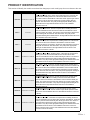
6 Rev. 1
Description
Gas Furnace Counterflow/Horizontal Induced Draft C Air Command 80 SSE
Furnace "C" Third Design Series "X" NOx Certified.
P1207501F - P1207508F 40" 80% furnace featuring integrated electronic ignition control, silicon
carbide ignitor, electrodepositioned textured steel cabinet and 409 stainless
steel tubular heat exchanger.
Gas Furnace Counterflow/Horizontal Induced Draft C Air Command 80 SSE
Furnace "D" Fourth Design Series "X" NOx Certified.
40" 80% furnace featuring integrated electronic ignition control, silicon
P1226801F - P1226807F carbide ignitor and 409 stainless steel tubular heat exchanger. Use of
smooth cold rolled steel substrate and a smooth top coat for furnace cabinet
to replace prepainted furnaces until new coating is approved for prepainted
material.
Gas Furnace Counterflow/Horizontal Induced Draft C Air Command 80 SSE
Furnace "C" Third Design Series "X" NOx Certified.
40" 80% furnace featuring integrated electronic ignition control, silicon
P1230401F - P1230408F
carbide ignitor and 409 stainless steel tubular heat exchanger. Release of
prepainted G30 galvanized steel cabinet parts to replace post painted parts
on furnace.
Gas Furnace Counterflow/Horizontal Induced Draft C Air Command 80 SSE
Furnace "C" Third Design Series "X" NOx Certified.
40" 80% furnace featuring integrated electronic ignition control, silicon
P1230501F - P1230508F
carbide ignitor, electrodepositioned textured steel cabinet and 409 stainless
steel tubular heat exchanger. Change from embossed bottom knock-out to
perforated bottom knock-out and addition of internal side filter retention.
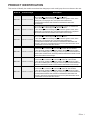
PRODUCT IDENTIFICATION
This section will identify the models covered and the changes per each model group from one release to the next.
Model #
Manufacturing #
Description
Gas Furnace Upflow/Horizontal Induced Draft D Air Command 80 SV
Furnace "C" Third Design Series "A" Standard Unit (not NOx certified).
40" 80% furnace featuring integrated electronic ignition control, silicon
carbide ignitor, electrodepositioned textured steel cabinet and aluminized
steel tubular heat exchanger.
Gas Furnace Upflow/Horizontal Induced Draft D Air Command 80 SV
Furnace "C" Third Design Series "X" NOx Certified.
40" 80% furnace featuring integrated electronic ignition control, silicon
carbide ignitor, electrodepositioned textured steel cabinet and aluminized
steel tubular heat exchanger.
Gas Furnace Upflow/Horizontal Induced Draft D Air Command 80 SV
Furnace "C" Third Design Series "X" NOx Certified.
40" 80% furnace featuring integrated electronic ignition control, silicon
carbide ignitor, electrodepositioned textured steel cabinet and aluminized
steel tubular heat exchanger. Release of Fasco induced draft blower to
replace Jakel induced draft blower.
Gas Furnace Upflow/Horizontal Induced Draft D Air Command 80 SV
Furnace "C" Third Design Series "A" Standard Unit (not NOx certified).
40" 80% furnace featuring integrated electronic ignition control, silicon
carbide ignitor, prepainted textured steel cabinet and aluminized steel
tubular heat exchanger. Release of Fasco induced draft blower to replace
Jakel induced draft blower.
GUID***CA**
P1212401F - P1212407F
GUID***CX**
P1212501F - P1212507F
GUID***CX**
P1220501F - P1220507F
GUID***CA**
P1220601F - P1220607F
GUID***DA**
Gas Furnace Upflow/Horizontal Induced Draft D Air Command 80 SV
Furnace "D" Fourth Design Series "A" Standard Unit (not NOx certified).
40" 80% furnace featuring integrated electronic ignition control, silicon
P1226901F - P1226911F carbide ignitor and aluminized steel tubular heat exchanger. Use of smooth
cold rolled steel substrate and a smooth top coat for furnace cabinet to
replace prepainted furnaces until new coating is approved for prepainted
material.
GUID***DX**
Gas Furnace Upflow/Horizontal Induced Draft D Air Command 80 SV
Furnace "D" Fourth Design Series "X" NOx Certified.
40" 80% furnace featuring integrated electronic ignition control, silicon
P1227001F - P1227009F carbide ignitor, prepainted textured steel cabinet and aluminized steel
tubular heat exchanger. Use of 10x8 blower assembly on 070__40 model
to upgrade airflow to a full 4 tons of air for air conditioning and also release
of new circulation motor on 090,115 and 140__50 models.
GUID***CA**
P1229401F - P1229407F
GUID***CA**
P1229501F - P1229507F
GUID***CX**
P1229601F - P1229607F
GUID***CX**
P1229701F - P1229705F
Gas Furnace Upflow/Horizontal Induced Draft D Air Command 80 SV
Furnace "C" Third Design Series "A" Standard Unit (not NOx certified).
40" 80% furnace featuring integrated electronic ignition control, silicon
carbide ignitor, prepainted textured steel cabinet and aluminized steel
tubular heat exchanger.
Gas Furnace Upflow/Horizontal Induced Draft D Air Command 80 SV
Furnace "C" Third Design Series "A" Standard Unit (not NOx certified).
40" 80% furnace featuring integrated electronic ignition control, silicon
carbide ignitor, electrodepositioned textured steel cabinet and aluminized
steel tubular heat exchanger.
Gas Furnace Upflow/Horizontal Induced Draft D Air Command 80 SV
Furnace "C" Third Design Series "A" Standard Unit (not NOx certified).
40" 80% furnace featuring integrated electronic ignition control, silicon
carbide ignitor, prepainted textured steel cabinet and aluminized steel
tubular heat exchanger.
Gas Furnace Upflow/Horizontal Induced Draft D Air Command 80 SV
Furnace "C" Third Design Series "X" NOx Certified.
40" 80% furnace featuring integrated electronic ignition control, silicon
carbide ignitor, electrodepositioned textured steel cabinet and aluminized
steel tubular heat exchanger.
7 Rev. 1
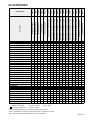
PRODUCT IDENTIFICATION
This section will identify the models covered and the changes per each model group from one release to the next.
Model #
Manufacturing #
GUIS***CA**
Gas Furnace Upflow/Horizontal Induced Draft S 2-Stage, Air Command 80 SSE II
Furnace "C" Third Design Series "A" Standard Unit (not NOx certified).
P1211003F - P1211008F 40" 80% two-stage furnace featuring integrated electronic ignition control, two-stage
gas valve, two-speed induced draft blower, silicon carbide ignitor, electrodepositioned
textured steel cabinet and 409 stainless steel tubular heat exchanger.
GUIS***CX**
Gas Furnace Upflow/Horizontal Induced Draft S 2-Stage, Air Command 80 SSE II
Furnace "C" Third Design Series "X" NOx Certified.
40" 80% two-stage furnace featuring integrated electronic ignition control, silicon
P1211103F - P1211107F
carbide ignitor, two-stage gas valve, two-speed induced draft blower,
electrodepositioned textured steel cabinet and 409 stainless steel tubular heat
exchanger.
GUIS070DA35
P1227103F
Description
Gas Furnace Upflow/Horizontal Induced Draft S 2-Stage, Air Command 80 SSE II
Furnace "D" Fourth Design Series "A" Standard Unit (not NOx certified).
40" 80% two-stage furnace featuring integrated electronic ignition control, silicon
carbide ignitor, two-stage gas valve, two-speed induced draft blower and 409 stainless
steel tubular heat exchanger. Use of smooth cold rolled steel substrate and a smooth
top coat for furnace cabinet to replace prepainted furnaces until new coating is
approved for prepainted material.
GUIS***CA**
Gas Furnace Upflow/Horizontal Induced Draft S 2-Stage, Air Command 80 SSE II
Furnace "C" Third Design Series "A" Standard Unit (not NOx certified).
P1229803F - P1229808F 40" 80% two-stage furnace featuring integrated electronic ignition control, silicon
carbide ignitor, two-stage gas valve, two-speed induced draft blower, prepainted
textured steel cabinet and 409 stainless steel tubular heat exchanger.
GUIS***CA**
Gas Furnace Upflow/Horizontal Induced Draft S 2-Stage, Air Command 80 SSE II
Furnace "C" Third Design Series "A" Standard Unit (not NOx certified).
40" 80% two-stage furnace featuring integrated electronic ignition control, silicon
P1229903F - P1229907F carbide ignitor, two-stage gas valve, two-speed induced draft blower,
electrodepositioned textured steel cabinet and 409 stainless steel tubular heat
exchanger. Change from embossed bottom knock-out to perforated bottom knock-out
and addition of internal side filter retention.
GUIS***CX**
Gas Furnace Upflow/Horizontal Induced Draft S 2-Stage, Air Command 80 SSE II
Furnace "C" Third Design Series "X" NOx Certified.
P1230003F - P1230007F
40" 80% furnace featuring integrated electronic ignition control, silicon carbide ignitor,
prepainted textured steel cabinet and 409 stainless steel tubular heat exchanger.
GUIS***CX**
Gas Furnace Upflow/Horizontal Induced Draft S 2-Stage, Air Command 80 SSE II
Furnace "C" Third Design Series "X" NOx Certified.
40" 80% furnace featuring integrated electronic ignition control, silicon carbide ignitor,
P1230103F - P1230107F
electrodepositioned textured steel cabinet and 409 stainless steel tubular heat
exchanger. Change from embossed bottom knock-out to perforated bottom knock-out
and addition of internal side filter retention.
8 Rev. 1
PRODUCT IDENTIFICATION
This section will identify the models covered and the changes per each model group from one release to the next.
Model #
Manufacturing #
Description
GCIS***CX**
Gas Furnace Counterflow/Horizontal Induced Draft S 2-Stage, Air Command 80
SSE II Furnace "C" Third Design Series "X" NOx Certified.
40" 80% two-stage furnace featuring integrated electronic ignition control, silicon
P1211203F - P1211205F
carbide ignitor, two-stage gas valve, two-speed induced draft blower,
electrodepositioned textured steel cabinet and 409 stainless steel tubular
heat exchanger.
GCIS***CX**
Gas Furnace Counterflow/Horizontal Induced Draft S 2-Stage, Air Command 80
SSE II Furnace "C" Third Design Series "X" NOx Certified.
P1230603F - P1230605F 40" 80% two-stage furnace featuring integrated electronic ignition control, silicon
carbide ignitor, two-stage gas valve, two-speed induced draft blower, prepainted
textured steel cabinet and 409 stainless steel tubular heat exchanger.
GCIS***CX**
Gas Furnace Counterflow/Horizontal Induced Draft S 2-Stage, Air Command 80
SSE II Furnace "C" Third Design Series "X" NOx Certified.
40" 80% two-stage furnace featuring integrated electronic ignition control, silicon
P1230703F - P1230705F carbide ignitor, two-stage gas valve, two-speed induced draft blower,
electrodepositioned textured steel cabinet and 409 stainless steel tubular heat
exchanger. Change from embossed bottom knock-out to perforated bottom knockout and addition of internal side filter retention.
GUIV***DX**
Gas Furnace Upflow/Horizontal Induced Draft Variable Speed, 2-Stage, Air
Command 80 SSE II Q Furnace "D" Fourth Design Series "X" NOx Certified.
40" 80% two-stage variable speed furnace featuring integrated electronic ignition
P1227403F - P1227408F
control, silicon carbide ignitor, two-stage gas valve, two-speed induced draft blower,
variable speed circualtor blower, electrodepositioned textured steel cabinet and 409
stainless steel tubular heat exchanger.
GUIV***CX**
Gas Furnace Upflow/Horizontal Induced Draft Variable Speed, 2-Stage, Air
Command 80 SSE II Q Furnace "C" Third Design Series "X" NOx Certified.
P1230203F - P1230208F 40" 80% two-stage variable speed furnace featuring integrated electronic ignition
control, silicon carbide ignitor, two-stage gas valve, two-speed induced draft blower,
prepainted textured steel cabinet and 409 stainless steel tubular heat exchanger.
GUIV***CX**
Gas Furnace Upflow/Horizontal Induced Draft Variable Speed, 2-Stage, Air
Command 80 SSE II Q Furnace "C" Third Design Series "X" NOx Certified.
40" 80% two-stage variable speed furnace featuring integrated electronic ignition
P1230303F - P1230308F control, silicon carbide ignitor, two-stage gas valve, two-speed induced draft blower,
electrodepositioned textured steel cabinet and 409 stainless steel tubular heat
exchanger. Change from embossed bottom knock-out to perforated bottom knockout and addition of internal side filter retention.
9 Rev. 1
PRODUCT IDENTIFICATION
This section will identify the models covered and the changes per each model group from one release to the next.
Model #
Manufacturing #
Description
GUCA***AX**
Gas Furnace Upflow/Horizontal Condensing A Air Command 90 Furnace
"A" First Design Series "X" NOx Certified.
P1219301F - P1219306F 40" 90% furnace featuring integrated electronic ignition control, silicon
carbide mini ignitor, electrodepositioned steel cabinet and 409 stainless
steel tubular heat exchanger and stainless steel recouperative coil.
GUCA***AX**
Gas Furnace Upflow/Horizontal Condensing A Air Command 90 Furnace
"A" First Design Series "X" NOx Certified.
P1227501F - P1227506F 40" 90% furnace featuring integrated electronic ignition control, silicon
carbide mini ignitor, electrodepositioned steel cabinet and 409 stainless
steel tubular heat exchanger and stainless steel recouperative coil.
GUCA***AX**
Gas Furnace Upflow/Horizontal Condensing A Air Command 90 Furnace.
"A" First Design Series "X" NOx Certified.
P1228801F - P1228806F 40" 90% furnace featuring integrated electronic ignition control, silicon
carbide mini ignitor, prepainted steel cabinet and 409 stainless steel tubular
heat exchanger and stainless steel recouperative coil.
GUCA***AX**
Gas Furnace Upflow/Horizontal Condensing A Air Command 90 Furnace
"A" First Design Series "X" NOx Certified.
40" 90% furnace featuring integrated electronic ignition control, silicon
P1228901F - P1228906F
carbide mini ignitor, electrodepositioned steel cabinet and 409 stainless
steel tubular heat exchanger and stainless steel recouperative coil and
stainless steel recouperative coil.
GCCA***AX**
Gas Furnace Counterflow/Horizontal Condensing A Air Command 90
Furnace "A" First Design Series "X" NOx Certified.
P1227601F - P1227606F 40" 90% furnace featuring integrated electronic ignition control, silicon
carbide mini ignitor, electrodepositioned steel cabinet and 409 stainless
steel tubular heat exchanger and stainless steel recouperative coil.
GCCA***AX**
Gas Furnace Counterflow/Horizontal Condensing A Air Command 90
Furnace "A" First Design Series "X" NOx Certified.
P1232401F - P1232406F 40" 90% furnace featuring integrated electronic ignition control, silicon
carbide ignitor, electrodepositioned steel cabinet and 409 stainless steel
tubular heat exchanger and stainless steel recouperative coil.
10 Rev. 1
PRODUCT IDENTIFICATION
This section will identify the models covered and the changes per each model group from one release to the next.
Model #
Manufacturing #
Description
GUVA***AX**
Gas Furnace Upflow/Horizontal Variable Speed, 2-Stage, Condensing A Air
Command 95 II Q Furnace "A" First Design Series "X" NOx Certified.
40" 95% two-stage variable speed furnace featuring integrated electronic
P1228301F - P1228306F
ignition control, silicon carbide mini ignitor, two-stage gas valve, two-speed
induced draft blower, electrodepositioned steel cabinet and 409 stainless steel
tubular heat exchanger and stainless steel recouperative coil.
GUVA***AX**
Gas Furnace Upflow/Horizontal Variable Speed, 2-Stage, Condensing A Air
Command 95 II Q Furnace "A" First Design Series "X" NOx Certified.
40" 95% two-stage variable speed furnace featuring integrated electronic
P1232501F - P1232506F
ignition control, silicon carbide mini ignitor, two-stage gas valve, two-speed
induced draft blower, electrodepositioned steel cabinet and 409 stainless steel
tubular heat exchanger and stainless steel recouperative coil.
GUVA***BX**
Gas Furnace Upflow/Horizontal Variable Speed, 2-Stage, Condensing A Air
Command 95 II Q Furnace "B" Second Design Series "X" NOx Certified.
40" 95% two-stage variable speed furnace featuring "intell-ignition" integrated
P1234701F - P1234706F
electronic ignition control, silicon nitride ignitor, two-stage gas valve, two-speed
induced draft blower, prepainted steel cabinet and 409 stainless steel tubular
heat exchanger.
GUSA***BX**
Gas Furnace Upflow/Horizontal S 2-Stage, Condensing A Air Command 90
Furnace "B" Second Design Series "X" NOx Certified.
40" 90% two-stage variable speed furnace featuring "intell-ignition" integrated
P1233902F - P1233906F
electronic ignition control, silicon nitride ignitor, two-stage gas valve, two-speed
induced draft blower, prepainted steel cabinet and 409 stainless steel tubular
heat exchanger.
11 Rev. 1
PRODUCT IDENTIFICATION
This section will identify the models covered and the changes per each model group from one release to the next.
Model #
Manufacturing #
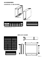
ASB01
P1200201F - P1200202F
CFB16-24
P1228001F - P1228003F
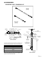
CVK4-7
DEHUM1
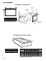
EFR01
FTK03A
HAC1PS1-14
12 Rev. 1
P1210001F- P1210004F
Description
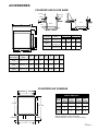
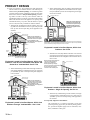
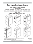
Adjustable Subbase Kit. For use with Amana furnace models GCIA, GCIB,
GCIC and GCIS: Must be used to prevent excessive temperature from
reaching combustible materials, if the furnace is installed on a combustible
floor. This subbase effectively separated the furnace base and plenum
from combustible materials. To ensure safe installation, do not install the
counterflow floor base directly on carpeting, tile, or other combustible
material other than wood flooring.
Counterflow Floor Base Kit. For use with Amana furnace models GCCA:
Must be used to prevent excessive temperature from reaching combustible
materials, if the furnace is installed on a combustible floor. This subbase
effectively separated the furnace base and plenum from combustible
materials. To ensure safe installation, do not install the counterflow floor
base directly on carpeting, tile, or other combustible material other than
wood flooring.
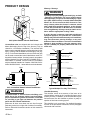
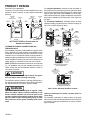
Common Vent Kit. For use with Amana 80% furnace models GUIA, GUIB,
GUIC, GUID, GCIA, GCIB and GCIC. Must be used on each furnace that
is common vented into type B-1 vent system. Only Amana Air Command
SSE and SV models listed can be common vented with this kit and may not
be common vented with any other type furnaces. The common vent kit is
not intended for use on other appliances. When the correct venting system
has been designed for the installation, a Common Vent Kit is selected.
These kits come in 4, 5, 6 and 7 inch versions.
Dehumidistat. For use with Amana two-stage variable speed furnace
models GUIV and GUVA. Wall mounted, 24 volt humidity control available
as a Dehumidistat used to reduce the airflow in the air conditioning mode
when necessary to lower the humidity in an occupied home to prevent dew
P1227801F
build-up associated with high humidity levels. This control features a
moisture-sensitive nylon element and also provides positive ON-OFF
settings for manual operation. The control is a normally closed switch that
opens on humidity rise causing the blower to switch to a lower speed to
control the humidity within the structure.
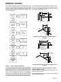
External Filter Rack Kit. For use with Amana upflow furnace models GUIA,
GUIB, GUIC, GUID, GUIS, GUCA, GUVA and GUSA. This kit is intended
to provide a location, external to the furnace casing, for installation of a
P1221001F
permanent filter. The rack is mounted over the indoor air blower
compartment area of either side panel, and provide filter retention as well
as a location for attaching return air ductwork.
Furnace Twinning Kit. This kit allows two Amana Air Command gas
furnaces containing an Integrated Ignition control to operate at the same
time from a single thermostat. The two furnaces to be "twinned" must be
P1171303F - P1171305F the exact same model with their circulating air blowers set to deliver the
same air flow at the same time. The furnaces may deliver different CFM's
in the cooling mode, if applicable. This kit cannot be used to control more
than two furnaces.
High Altitude Pressure Switch Kit. For use with Amana furnace models
GUIA, GUIB, GUIC, GUID, GCIA, GCIB and GCIC . These kits contain a
P1204211F - P1204226F
high altitude Category I pressure switch that must be used at altitudes
above the rated altitudes because of reduced air density.
PRODUCT IDENTIFICATION
This section will identify the models covered and the changes per each model group from one release to the next.
Model #
HALP05-09
HALP10
HALP11
HANG07
Manufacturing #
Description
High Altitude Propane Gas Conversion Kit. For use with Amana furnace
models GUIA, GUIB, GUIC, GUID, GCIA, GCIB and GCIC. These kits are
required when installing Amana Air Command 80 SSE and SV furnaces
above their maximum rated altitude. These kits contain propane gas orifices.
P1129105F - P1129111F
The orifices in the kit have been selected as a result of testing with the
American Gas Association. They will provide appropriate derating at the
altitude listed in the High Altitude Charts as shown in the installation
instructions of the kit.
High Altitude Propane Gas Conversion Kit. For use with Amana furnace
models GUCA and GCCA. This kit is required when installing Amana Air
Command 90 SSE furnaces above their maximum rated altitude. This kit
P1129112F
contains propane gas orifices. The orifices in the kit have been selected as a
result of testing with the American Gas Association. They will provide
appropriate derating at the altitude listed in the High Altitude Charts as shown
in the installation instructions of the kit.
High Altitude Propane Gas Conversion Kit. For use with Amana furnace
models GUVA. This kit is required when installing Amana Air Command 95
SSE furnaces above their maximum rated altitude. These kits contain
P1129113F
propane gas orifices. The orifices in the kit have been selected as a result of
testing with the American Gas Association. They will provide appropriate
derating at the altitude listed in the High Altitude Charts as shown in the
installation instructions of the kit.
P1129007F - P1129010F
High Altitude Natural Gas Kit. For use with Amana furnace models GUIA,
GUIB, GUIC, GUID, GCIA, GCIB and GCIC. These kits are required when
installing Amana Air Command 80 SSE and SV furnaces above their
maximum rated altitude. This kit contains natural gas orifices. The orifices in
the kit have been selected as a result of testing with the American Gas
Association. They will provide appropriate derating at the altitude listed in the
High Altitude Charts as shown in the installation instructions of the kit.
High Altitude Natural Gas Kit. For use with Amana furnace models GUCA
and GCCA. These kits are required when installing Amana Air Command 90
SSE furnaces above their maximum rated altitude. This kit contains natural
gas orifices. The orifices in the kit have been selected as a result of testing
with the American Gas Association. They will provide appropriate derating at
the altitude listed in the High Altitude Charts as shown in the installation
instructions of the kit.
High Altitude Natural Gas Kit. For use with Amana furnace models GUVA.
These kits are required when installing Amana Air Command 95 SSE
furnaces above their maximum rated altitude. This kit contains natural gas
orifices. The orifices in the kit have been selected as a result of testing with
the American Gas Association. They will provide appropriate derating at the
altitude listed in the High Altitude Charts as shown in the installation
instructions of the kit.
High Altitude Pressure Switch Kit. For use with Amana furnace models
GUCA, GCCA and GUVA. This kit contains a high altitude pressure switch
that must be used at altitudes above the rated altitudes because of reduced
air density.
HANG11-12
P1210305F - P1210306F
HANG13-14
P1210307F - P1210308F
HAPS27-29
P1210518F - P1210520F
HATS01-09
High Altitude Two-Stage Conversion Kit. For use with Amana furnace models
GUIS, GCIS and GUIV. These kits are required when installing Amana Air
Command 80 SSE II furnaces above their maximum rated altitude. These kits
contain a pressure switch assembly and natural gas orifices. The orifices in
P1220406F - P1220414F the kit have been selected as a result of testing with the American Gas
Association. They will provide appropriate derating at the altitude listed in the
High Altitude Charts as shown in the installation instructions of the kit. A
different pressure switch must be used at altitudes above the rated altitudes
because of reduced air density.
13 Rev. 1
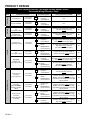
PRODUCT IDENTIFICATION
This section will identify the models covered and the changes per each model group from one release to the next.
Model #
Manufacturing #
HCVK
P1211401F
LPTK09
P1200108F
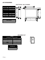
MAC1
MAF1
TSRK01
VCVK
14 Rev. 1
Description
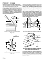
Horizontal Concentric Vent Kit. For use with Amana furnace models GUCA,
GCCA, GUVA and GUSA. This kit is designed to allow terminations of a
direct vent furnace to be "concentrically" vented through a wall. This kit allows
a single penetration to support terminations for both the vent/flue and the
combustion air intake pipe. Horizontal concentric vent kits can be installed
through walls having a minimum thickness of 3/4 inch to a maximum of 133/4 inches thickness. This kit is not certified for, and must not be applied to
any furnace not listed above.
Propane Conversion Kit. For use with Amana Air Command furnace models
GUIA, GUIB, GUIC, GUID, GCIA, GCIB, GCIC, GUIS, GCIS, GUIV, GUCA,
GCCA, GUVA and GUSA. This kit converts Amana gas fired units from
natural to propane gas. The conversion from natural gas (as shipped from the
factory) to propane gas requires: replacing the burner orifices, replacing gas
valve regulator spring (all single stage units), removing NOx
screens/turbulators (screens/turbulators not used on all units) and applying
identification labels.
P1221801F
Media Air Cleaner. For use with all Amana furnace models. The Amana
Media Air Cleaner (Air Bear ) is a high efficiency air filtration device designed
to remove dirt, dust, pollen and other microscopic particles from the air
passing through it. Flexible performance range up to 2,000 CFM capacity.
The air cleaner should be installed in the system so that all the system air is
circulated through the air cleaner. The air cleaner will only remove the
airborne contaminants delivered to it. Maximum performance is obtained
when the system blower is set for continuous operation. Note: The Amana
Media series of air cleaners can easily be upgraded to a highly efficient EAC5
Electronic Air Cleaner with a permanent washable collecting cell.
P1221901F
Media Air Filter. The filter in the Amana Media Air Cleaner (MAC1) must be
replaced periodically. The filter cartridges should be replaced with a Trion Air
Bear filter cartridge. These come from Amana in cartons of three. The
frequency of filter replacement if best determined by visual examination. With
typical residential use the approximate replacement period is 9 - 12 months.
P1232601F
Two-Stage Relay Kit. For use with Amana two-stage furnace models GUIS,
GCIS, GUIV and GUVA-AX. This kit enables the use of a single stage
thermostat with any Amana two-stage furnace. The time delay activates the
second stage of heat after the furnace has run a set period of time
(adjustable) on low stage heat. The time delay is adjustable from 6 to 20
minutes. The time delay starts the moment the thermostat initially calls for
heat. Longer time delays will be more energy efficient, while shorter time
delays will heat the home faster when the heating demand is high.
P1211402F
Vertical Concentric Vent Kit. For use with Amana furnace models GUCA,
GCCA, GUVA and GUSA. This kit is designed to allow terminations of a
direct vent furnace to be "concentrically" vented through the roof. This kit
allows a single penetration to support terminations for both the vent/flue and
the combustion air intake pipe. Vertical concentric vent kits can be installed
through roof penetrations having a minimum of 3/4 inch to a maximum of 22
inches thickness.This kit is not certified for, and must not be applied to any
furnace not listed above. Note: This kit is not certified for, and must not be
applied to any furnace not listed above.
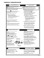
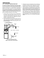
PRODUCT IDENTIFICATION
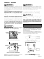
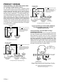
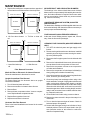
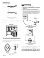
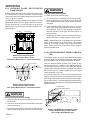
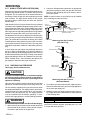
FOR YOUR SAFETY
READ BEFORE OPERATING
WARNING: If you do not follow these instructions
explosion may result causing property damage,
personal injury or loss of life.
A. This appliance does not have a pilot. It is equipped
with an ignition device which automatically lights
the burner. Do not try to light the burner by hand.
B. BEFORE OPERATING smell all around the appliance
area for gas. Be sure to smell next to the floor
because some gas is heavier than air and will
settle on the floor.
WHAT TO DO IF YOU SMELL GAS
Do not try to light any appliance.
Do not touch any electric switch;
do not use any phone in your building.
Immediately call your gas supplier from a neighbor's
phone. Follow the gas supplier's instructions.
If you cannot reach your gas supplier,
call the fire department.
C. Use only your hand to turn the gas control knob.
Never use tools. If the knob will not turn by
hand, don't try to repair it, call a qualified service
technician. Force or attempted repair may result in a fire
or explosion.
D. Do not use this appliance if any part has been underwater.
Immediately call a qualified service technician to inspect
the appliance and to replace any part of the control
system and any gas control which has been underwater.
LIRE AVANT DE METTRE
EN MARCHELIRE
AVERTISSEMENT: Quiconque ne respecte pas á
la lettre les instructions dans le présent manuel
risque de déclecher un incendie ou une explosion
entraînant des dammages matériels, des lésions
corporelles ou la perte de vies humaines.
A.
Cet appareil ne comporte pas de veilleuse. Il est
muni d'un dispositif d'allumage qui allume
automatiquement le brûleur. Ne pas tenter
d'allumer le brûleur manuellement.
B. AVANT DE LE FAIRE FONCTIONNER,
renifler tout autour de l'appariel pour déceler
une odeur de gaz. Renifler près du plancher, car
certains gaz sont plus lourds que l'air et
peuvent s'accumuler au niveau du so.l
QUE FAIRE S'IL Y A UNE ODEUR DE GAZ
Ne pas tenter d'allumer l'appariel
Ne toucher aucun interrupteur électrique;
n'utiliser aucun téléphone dans le bâtiment.
Appeler immédiatement le fournisseur de gaz
en employant le téléphone dún voisin.
Respecter à la lettre les instructions du
fournisseur de gaz.
Si personne ne répond, appeler le service des
incendies.
C. Ne pousser ou tourner le robinet d'admission du gaz
qu'à la main; ne jamais emploer d'outil à cet effet.
Si la manette reste coincée, ne pas tenter de la
réparer; appeler un technicien qualifié. Quiconque
tente de forcer la manette ou de la reparer peut
déclencher une explosion ou un incendie.
D. Ne pas se servir de cet appareil s'il a été plongé
dans l'eau, complètement ou en partie. Appeler un
technicien qualifié pour inspecter l'appareil et
remplacer tout partie du système de contrôle et
toute commande qui ont été plongés dans l'eau.
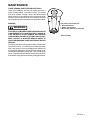
MISE EN MARCHE
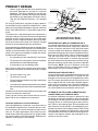
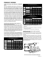
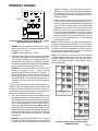
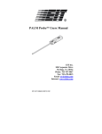
OPERATING INSTRUCTIONS
1. STOP! Read the safety information above on
this label.
2. Set the thermostat to lowest setting.
3. Turn off all power to the appliance.
4. This appliance is equipped with an ignition.
device which automatically lights the burner.
Do not try to light the burner by hand.
5. Turn the gas control knob clockwise
to
"OFF" Position. Do not force.
6. Wait five (5) minutes to clear out any gas. Then
smell for gas, including near the floor. If you
then smell gas, STOP! Follow "B" in the safety
information above on this Label.
ROBINET A GAZ
MANUEL, EN POS
If you don't smell gas, go to
"ON/MARCHE"
next step.
7. Turn gas control knob
GAS
counterclockwise
to "ON".
INLET
8. Replace access panel.
9. Turn on all electric
power to the appliance.
ARRIVEE
10.Set thermostat to desired setting.
DU GAZ
11.If the appliance will not operate,
follow the instructions "To Turn
Off Gas To Appliance" and call your
MANUAL GAS
service technician or gas company.
1. ARRETÊR! Lisez les instructions de sécurité sur
la portion supérieure de cette étiquette.
. 2. Régler le thermostat à la température la plus basse
3. Couper l'alimentation électrique de l'appareil.
4. Cet appareil ménager étant doté d'un système
d'allumage automatique, ne pas essayer à
allumer le brûleur manuellement.
5. Torner le robinet a gaz dans le sens des aigilles
d'une montre
en position "OFF/ARRET"
6. Attendre cinq (5) minutes pour laisser echapper tout le
gaz. Renifler tout autour de l'appareil, y compris près du
plancher, pour déceler une odeur de gaz. Si c'est le cas,
ARRETER! Passer à l'étape B des instructions de sécuritié
sur la portion supérieure de cette étiquette.
S'il n'y a pas d'odeur de gaz, passer à l'étape suivanté.
7. T ourner le robinet a gaz dans le sens inverse des
aigilles d'ne montre
en pos "ON/MARCHE".
8. Remettre en place le panneau d'accés.
9. Mettre l'appareil sous tension.
10. Régler le thermostat à la température desirée.
11. Si l'appareil ne se met pas en marche, suiyre les
instructions intitulées. Comment coupler l'admission
de gaz de l'appereil et appeler un technicien
qualifié ou le fourrnisseur de gaz.
OFF
ON
Hone ywe ll
KNOB SHOWN
IN "ON" POSITION
TO TURN OFF GAS TO APPLIANCE
1. Set the thermostat to lowest setting.
2. Turn off all electric power to the appliance
if service is to be performed.
3. Turn the gas control knob clockwise
to
"OFF" Position. Do not force.
4. Replace control access panel.
POUR COUPER L'ADMISSION
DE GAZ DE L'APPAREIL
1. Régler le thermostat à la température la plus basse.
2. Couper l'alimentation électrique de l'appareil s'il
faut procéder à des opérations d'entretien.
3. Torner le robinet a gaz dans le sens des aigilles
d'une montre
en position "OFF/ARRET".
Ne pas forcer.
4. Remettre en place le panneau d'accès.
11072702
15 Rev. 1
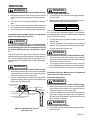
PRODUCT IDENTIFICATION
FOR YOUR SAFETY
READ BEFORE OPERATING
WARNING: If you do not follow these instructions
LIRE AVANT DE METTRE
EN MARCHELIRE
AVERTISSEMENT: Quiconque ne respecte pas á
explosion may result causing property damage,
personal injury or loss of life.
la lettre les instructions dans le présent manuel
risque de déclecher un incendie ou une explosion
entraînant des dammages matériels, des lésions
corporelles ou la perte de vies humaines.
A. This appliance does not have a pilot. It is equipped
with an ignition device which automatically lights
the burner. Do not try to light the burner by hand.
A.
B. BEFORE OPERATING smell all around the appliance
area for gas. Be sure to smell next to the floor
because some gas is heavier than air and will
settle on the floor.
Cet appareil ne comporte pas de veilleuse. Il est
muni d'un dispositif d'allumage qui allume
automatiquement le brûleur. Ne pas tenter
d'allumer le brûleur manuellement.
B. AVANT DE LE FAIRE FONCTIONNER,
renifler tout autour de l'appariel pour déceler
une odeur de gaz. Renifler près du plancher, car
certains gaz sont plus lourds que l'air et
peuvent s'accumuler au niveau du so.l
WHAT TO DO IF YOU SMELL GAS
Do not try to light any appliance.
Do not touch any electric switch;
do not use any phone in your building.
Immediately call your gas supplier from a neighbor's
phone. Follow the gas supplier's instructions.
If you cannot reach your gas supplier,
call the fire department.
QUE FAIRE S'IL Y A UNE ODEUR DE GAZ
Ne pas tenter d'allumer l'appariel
Ne toucher aucun interrupteur électrique;
n'utiliser aucun téléphone dans le bâtiment.
Appeler immédiatement le fournisseur de gaz
en employant le téléphone dún voisin.
Respecter à la lettre les instructions du
fournisseur de gaz.
Si personne ne répond, appeler le service des
incendies.
C. Ne pousser ou tourner le robinet d'admission du gaz
qu'à la main; ne jamais emploer d'outil à cet effet.
Si la manette reste coincée, ne pas tenter de la
réparer; appeler un technicien qualifié. Quiconque
tente de forcer la manette ou de la reparer peut
déclencher une explosion ou un incendie.
C. Use only your hand to turn the gas control knob.
Never use tools. If the knob will not turn by
hand, don't try to repair it, call a qualified service
technician. Force or attempted repair may result in a fire
or explosion.
D. Do not use this appliance if any part has been underwater.
Immediately call a qualified service technician to inspect
the appliance and to replace any part of the control
system and any gas control which has been underwater.
D. Ne pas se servir de cet appareil s'il a été plongé
dans l'eau, complètement ou en partie. Appeler un
technicien qualifié pour inspecter l'appareil et
remplacer tout partie du système de contrôle et
toute commande qui ont été plongés dans l'eau.
MISE EN MARCHE
OPERATING INSTRUCTIONS
1. ARRETÊR! Lisez les instructions de sécurité sur
la portion supérieure de cette étiquette.
. 2. Régler le thermostat à la température la plus basse
3. Couper l'alimentation électrique de l'appareil.
4. Cet appareil ménager étant doté d'un système
d'allumage automatique, ne pas essayer à
allumer le brûleur manuellement.
5. Torner le robinet a gaz dans le sens des aigilles
d'une montre
ROBINET A GAZ
MANUEL, EN POS
"ON/MARCHE"
PILOT A DJ
ON
ARRIVEE
DU GAZ
MANUAL GAS
KNOB SHOWN
IN "ON" POSITION
TO TURN OFF GAS TO APPLIANCE
1. Set the thermostat to lowest setting.
2. Turn off all electric power to the appliance
if service is to be performed.
3. Turn the gas control knob clockwise
to
"OFF" Position. Do not force.
4. Replace control access panel.
GAS
INLET
en position "OFF/ARRET"
6. Attendre cinq (5) minutes pour laisser echapper tout le
gaz. Renifler tout autour de l'appareil, y compris près du
plancher, pour déceler une odeur de gaz. Si c'est le cas,
ARRETER! Passer à l'étape B des instructions de sécuritié
sur la portion supérieure de cette étiquette.
S'il n'y a pas d'odeur de gaz, passer à l'étape suivanté.
7. T ourner le robinet a gaz dans le sens inverse des
aigilles d'ne montre
OFF
1. STOP! Read the safety information above on
this label.
2. Set the thermostat to lowest setting.
3. Turn off all power to the appliance.
4. This appliance is equipped with an ignition.
device which automatically lights the burner.
Do not try to light the burner by hand.
5. Turn the gas control knob clockwise
to
"OFF" Position. Do not force.
6. Wait five (5) minutes to clear out any gas. Then
smell for gas, including near the floor. If you
then smell gas, STOP! Follow "B" in the safety
information above on this Label.
If you don't smell gas, go to
next step.
7. Turn gas control knob
counterclockwise
to "ON".
8. Replace access panel.
9. Turn on all electric
power to the appliance.
10.Set thermostat to desired setting.
11.If the appliance will not operate,
follow the instructions "To Turn
Off Gas To Appliance" and call your
service technician or gas company.
en pos "ON/MARCHE".
8. Remettre en place le panneau d'accés.
9. Mettre l'appareil sous tension.
10. Régler le thermostat à la température desirée.
11. Si l'appareil ne se met pas en marche, suiyre les
instructions intitulées. Comment coupler l'admission
de gaz de l'appereil et appeler un technicien
qualifié ou le fourrnisseur de gaz.
POUR COUPER L'ADMISSION
DE GAZ DE L'APPAREIL
1. Régler le thermostat à la température la plus basse.
2. Couper l'alimentation électrique de l'appareil s'il
faut procéder à des opérations d'entretien.
3. Torner le robinet a gaz dans le sens des aigilles
d'une montre
en position "OFF/ARRET".
Ne pas forcer.
4. Remettre en place le panneau d'accès.
11072703
16 Rev. 1
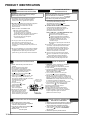
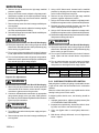
PRODUCT IDENTIFICATION
FOR YOUR SAFETY
READ BEFORE OPERATING
WARNING: If you do not follow these instructions
LIRE AVANT DE METTRE
EN MARCHELIRE
AVERTISSEMENT: Quiconque ne respecte pas á
explosion may result causing property damage,
personal injury or loss of life.
la lettre les instructions dans le présent manuel
risque de déclecher un incendie ou une explosion
entraînant des dammages matériels, des lésions
corporelles ou la perte de vies humaines.
A. This appliance does not have a pilot. It is equipped
with an ignition device which automatically lights
the burner. Do not try to light the burner by hand.
A.
B. BEFORE OPERATING smell all around the appliance
area for gas. Be sure to smell next to the floor
because some gas is heavier than air and will
settle on the floor.
Cet appareil ne comporte pas de veilleuse. Il est
muni d'un dispositif d'allumage qui allume
automatiquement le brûleur. Ne pas tenter
d'allumer le brûleur manuellement.
B. AVANT DE LE FAIRE FONCTIONNER,
renifler tout autour de l'appariel pour déceler
une odeur de gaz. Renifler près du plancher, car
certains gaz sont plus lourds que l'air et
peuvent s'accumuler au niveau du so.l
WHAT TO DO IF YOU SMELL GAS
Do not try to light any appliance.
Do not touch any electric switch;
do not use any phone in your building.
Immediately call your gas supplier from a neighbor's
phone. Follow the gas supplier's instructions.
If you cannot reach your gas supplier,
call the fire department.
QUE FAIRE S'IL Y A UNE ODEUR DE GAZ
Ne pas tenter d'allumer l'appariel
Ne toucher aucun interrupteur électrique;
n'utiliser aucun téléphone dans le bâtiment.
Appeler immédiatement le fournisseur de gaz
en employant le téléphone dún voisin.
Respecter à la lettre les instructions du
fournisseur de gaz.
Si personne ne répond, appeler le service des
incendies.
C. Ne pousser ou tourner le robinet d'admission du gaz
qu'à la main; ne jamais emploer d'outil à cet effet.
Si la manette reste coincée, ne pas tenter de la
réparer; appeler un technicien qualifié. Quiconque
tente de forcer la manette ou de la reparer peut
déclencher une explosion ou un incendie.
C. Use only your hand to turn the gas control knob.
Never use tools. If the knob will not turn by
hand, don't try to repair it, call a qualified service
technician. Force or attempted repair may result in a fire
or explosion.
D. Do not use this appliance if any part has been underwater.
Immediately call a qualified service technician to inspect
the appliance and to replace any part of the control
system and any gas control which has been underwater.
D. Ne pas se servir de cet appareil s'il a été plongé
dans l'eau, complètement ou en partie. Appeler un
technicien qualifié pour inspecter l'appareil et
remplacer tout partie du système de contrôle et
toute commande qui ont été plongés dans l'eau.
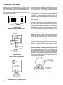
MISE EN MARCHE
OPERATING INSTRUCTIONS
1. STOP! Read the safety information above on
this label.
2. Set the thermostat to lowest setting.
3. Turn off all power to the appliance.
4. This appliance is equipped with an ignition.
device which automatically lights the burner.
Do not try to light the burner by hand.
5. Turn the gas control lever clockwise
to
"OFF" Position. Do not force.
6. Wait five (5) minutes to clear out any gas. Then
smell for gas, including near the floor. If you
then smell gas, STOP! Follow "B" in the safety
information above on this Label.
If you don't smell gas, go to
next step.
7. Turn gas control lever
counterclockwise
to "ON".
8. Replace access panel.
9. Turn on all electric
power to the appliance.
10.Set thermostat to desired setting.
11.If the appliance will not operate,
follow the instructions "To Turn
Off Gas To Appliance" and call your
service technician or gas company.
LEVIER A GAZ
MANUEL, EN POS
"ON/MARCHE"
GAS
INLET
ARRIVEE
DU GAZ
aigilles d'ne montre
en pos "ON/MARCHE".
8. Remettre en place le panneau d'accés.
9. Mettre l'appareil sous tension.
10. Régler le thermostat à la température desirée.
11. Si l'appareil ne se met pas en marche, suiyre les
instructions intitulées. Comment coupler l'admission
de gaz de l'appereil et appeler un technicien
qualifié ou le fourrnisseur de gaz.
MANUAL GAS
LEVER SHOWN
IN "ON" POSITION
TO TURN OFF GAS TO APPLIANCE
1. Set the thermostat to lowest setting.
2. Turn off all electric power to the appliance
if service is to be performed.
3. Turn the gas control lever clockwise
to
"OFF" Position. Do not force.
4. Replace control access panel.
1. ARRETÊR! Lisez les instructions de sécurité sur
la portion supérieure de cette étiquette.
. 2. Régler le thermostat à la température la plus basse
3. Couper l'alimentation électrique de l'appareil.
4. Cet appareil ménager étant doté d'un système
d'allumage automatique, ne pas essayer à
allumer le brûleur manuellement.
5. Torner le levier a gaz dans le sens des aigilles
d'une montre
en position "OFF/ARRET"
6. Attendre cinq (5) minutes pour laisser echapper tout le
gaz. Renifler tout autour de l'appareil, y compris près du
plancher, pour déceler une odeur de gaz. Si c'est le cas,
ARRETER! Passer à l'étape B des instructions de sécuritié
sur la portion supérieure de cette étiquette.
S'il n'y a pas d'odeur de gaz, passer à l'étape suivanté.
7. Tourner le levier a gaz dans le sens inverse des
POUR COUPER L'ADMISSION
DE GAZ DE L'APPAREIL
1. Régler le thermostat à la température la plus basse.
2. Couper l'alimentation électrique de l'appareil s'il
faut procéder à des opérations d'entretien.
3. Torner le levier a gaz dans le sens des aigilles
d'une montre
en position "OFF/ARRET".
Ne pas forcer.
4. Remettre en place le panneau d'accès.
11072706
17 Rev. 1
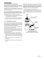
PRODUCT IDENTIFICATION
FOR YOUR SAFETY
READ BEFORE OPERATING
WARNING: If you do not follow these instructions
LIRE AVANT DE METTRE
EN MARCHELIRE
AVERTISSEMENT: Quiconque ne respecte pas á
explosion may result causing property damage,
personal injury or loss of life.
la lettre les instructions dans le présent manuel
risque de déclecher un incendie ou une explosion
entraînant des dammages matériels, des lésions
corporelles ou la perte de vies humaines.
A. This appliance does not have a pilot. It is equipped
with an ignition device which automatically lights
the burner. Do not try to light the burner by hand.
A.
B. BEFORE OPERATING smell all around the appliance
area for gas. Be sure to smell next to the floor
because some gas is heavier than air and will
settle on the floor.
Cet appareil ne comporte pas de veilleuse. Il est
muni d'un dispositif d'allumage qui allume
automatiquement le brûleur. Ne pas tenter
d'allumer le brûleur manuellement.
B. AVANT DE LE FAIRE FONCTIONNER,
renifler tout autour de l'appariel pour déceler
une odeur de gaz. Renifler près du plancher, car
certains gaz sont plus lourds que l'air et
peuvent s'accumuler au niveau du so.l
WHAT TO DO IF YOU SMELL GAS
Do not try to light any appliance.
Do not touch any electric switch;
do not use any phone in your building.
Immediately call your gas supplier from a neighbor's
phone. Follow the gas supplier's instructions.
If you cannot reach your gas supplier,
call the fire department.
QUE FAIRE S'IL Y A UNE ODEUR DE GAZ
Ne pas tenter d'allumer l'appariel
Ne toucher aucun interrupteur électrique;
n'utiliser aucun téléphone dans le bâtiment.
Appeler immédiatement le fournisseur de gaz
en employant le téléphone dún voisin.
Respecter à la lettre les instructions du
fournisseur de gaz.
Si personne ne répond, appeler le service des
incendies.
C. Ne pousser ou tourner le levier d'admission du gaz
qu'à la main; ne jamais emploer d'outil à cet effet.
Si la manette reste coincée, ne pas tenter de la
réparer; appeler un technicien qualifié. Quiconque
tente de forcer la manette ou de la reparer peut
déclencher une explosion ou un incendie.
C. Use only your hand to push in or turn the gas control lever.
Never use tools. If the lever will not push in or turn by
hand, don't try to repair it, call a qualified service
technician. Force or attempted repair may result in a fire
or explosion.
D. Do not use this appliance if any part has been underwater.
Immediately call a qualified service technician to inspect
the appliance and to replace any part of the control
system and any gas control which has been underwater.
D. Ne pas se servir de cet appareil s'il a été plongé
dans l'eau, complètement ou en partie. Appeler un
technicien qualifié pour inspecter l'appareil et
remplacer tout partie du système de contrôle et
toute commande qui ont été plongés dans l'eau.
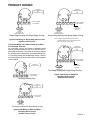
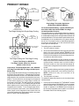
MISE EN MARCHE
OPERATING INSTRUCTIONS
1. STOP! Read the safety information above on
this label.
2. Set the thermostat to lowest setting.
3. Turn off all power to the appliance.
4. This appliance is equipped with an ignition.
device which automatically lights the burner.
Do not try to light the burner by hand.
5. Push the gas control lever to "OFF" Position.
Do not force.
6. Wait five (5) minutes to clear out any gas. Then
smell for gas, including near the floor. If you
LEVIER A GAZ
then smell gas, STOP! Follow "B"
MANUEL, EN POS
in the safety. Information above
"ON/MARCHE"
on this label if you don't smell
GAS
gas, go to next step.
INLET
7. Push gas control lever
to "ON".
8. Replace access panel.
ARRIVEE
9. Turn on all electric
DU GAZ
power to the appliance.
10.Set thermostat to desired setting.
MANUAL GAS
11.If the appliance will not operate,
LEVER SHOWN
follow the instructions "To Turn
IN ON POSITION
Off Gas To Appliance" and call your
service technician or gas company.
*
*
O
F
F
*
M
1
P
3
*
2
C
ON
*
*
TO TURN OFF GAS TO APPLIANCE
1. Set the thermostat to lowest setting.
2. Turn off all electric power to the appliance
if service is to be performed.
3. Push the gas control lever to "OFF" Position.
Do not force.
4. Replace control access panel.
*
1. ARRETÊR! Lisez les instructions de sécurité sur
la portion supérieure de cette étiquette.
. 2. Régler le thermostat à la température la plus basse
3. Couper l'alimentation électrique de l'appareil.
4. Cet appareil ménager étant doté d'un système
d'allumage automatique, ne pas essayer à
allumer le brûleur manuellement.
5. Pousse le levier du contrôle du gaz à "OFF/ ARRET"
position.
6. Attendre cinq (5) minutes pour laisser echapper tout le
gaz. Renifler tout autour de l'appareil, y compris près du
plancher, pour déceler une odeur de gaz. Si c'est le cas,
ARRETER! Passer à l'étape B des instructions de sécuritié
sur la portion supérieure de cette étiquette.
S'il n'y a pas d'odeur de gaz, passer à l'étape suivanté.
7. Pousse le levier du contrôle du gaz à "ON/MARCHE"
position.
8. Remettre en place le panneau d'accés.
9. Mettre l'appareil sous tension.
10. Régler le thermostat à la température desirée.
11. Si l'appareil ne se met pas en marche, suiyre les
instructions intitulées. Comment coupler l'admission
de gaz de l'appereil et appeler un technicien
qualifié ou le fourrnisseur de gaz.
POUR COUPER L'ADMISSION
DE GAZ DE L'APPAREIL
1. Régler le thermostat à la température la plus basse.
2. Couper l'alimentation électrique de l'appareil s'il
faut procéder à des opérations d'entretien.
3. Pousse le levier du contrôle du gaz à "OFF / ARRET"
position.
Ne pas forcer.
4. Remettre en place le panneau d'accès.
11072707
18 Rev. 1
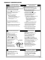
PRODUCT IDENTIFICATION
FOR YOUR SAFETY
READ BEFORE OPERATING
WARNING: If you do not follow these instructions
LIRE AVANT DE METTRE
EN MARCHELIRE
AVERTISSEMENT: Quiconque ne respecte pas á
explosion may result causing property damage,
personal injury or loss of life.
la lettre les instructions dans le présent manuel
risque de déclecher un incendie ou une explosion
entraînant des dammages matériels, des lésions
corporelles ou la perte de vies humaines.
A. This appliance does not have a pilot. It is equipped
with an ignition device which automatically lights
the burner. Do not try to light the burner by hand.
A.
B. BEFORE OPERATING smell all around the appliance
area for gas. Be sure to smell next to the floor
because some gas is heavier than air and will
settle on the floor.
Cet appareil ne comporte pas de veilleuse. Il est
muni d'un dispositif d'allumage qui allume
automatiquement le brûleur. Ne pas tenter
d'allumer le brûleur manuellement.
B. AVANT DE LE FAIRE FONCTIONNER,
renifler tout autour de l'appariel pour déceler
une odeur de gaz. Renifler près du plancher, car
certains gaz sont plus lourds que l'air et
peuvent s'accumuler au niveau du so.l
WHAT TO DO IF YOU SMELL GAS
Do not try to light any appliance.
Do not touch any electric switch;
do not use any phone in your building.
Immediately call your gas supplier from a neighbor's
phone. Follow the gas supplier's instructions.
If you cannot reach your gas supplier,
call the fire department.
QUE FAIRE S'IL Y A UNE ODEUR DE GAZ
Ne pas tenter d'allumer l'appariel
Ne toucher aucun interrupteur électrique;
n'utiliser aucun téléphone dans le bâtiment.
Appeler immédiatement le fournisseur de gaz
en employant le téléphone dún voisin.
Respecter à la lettre les instructions du
fournisseur de gaz.
Si personne ne répond, appeler le service des
incendies.
C. Ne pousser ou tourner le robinet d'admission du gaz
qu'à la main; ne jamais emploer d'outil à cet effet.
Si la manette reste coincée, ne pas tenter de la
réparer; appeler un technicien qualifié. Quiconque
tente de forcer la manette ou de la reparer peut
déclencher une explosion ou un incendie.
C. Use only your hand to turn the gas control knob.
Never use tools. If the knob will not turn by
hand, don't try to repair it, call a qualified service
technician. Force or attempted repair may result in a fire
or explosion.
D. Do not use this appliance if any part has been underwater.
Immediately call a qualified service technician to inspect
the appliance and to replace any part of the control
system and any gas control which has been underwater.
D. Ne pas se servir de cet appareil s'il a été plongé
dans l'eau, complètement ou en partie. Appeler un
technicien qualifié pour inspecter l'appareil et
remplacer tout partie du système de contrôle et
toute commande qui ont été plongés dans l'eau.
MISE EN MARCHE
OPERATING INSTRUCTIONS
1. ARRETÊR! Lisez les instructions de sécurité sur
1. STOP! Read the safety information above on
la portion supérieure de cette étiquette.
this label.
2. Set the thermostat to lowest setting.
. 2. Régler le thermostat à la température la plus basse
3. Couper l'alimentation électrique de l'appareil.
3. Turn off all power to the appliance.
4. Cet appareil ménager étant doté d'un système
4. This appliance is equipped with an ignition.
d'allumage automatique, ne pas essayer à
device which automatically lights the burner.
allumer le brûleur manuellement.
Do not try to light the burner by hand.
5. Torner le robinet a gaz dans le sens des aigilles
5. Turn the gas control knob clockwise
to
d'une montre
en position "OFF/ARRET"
"OFF" Position. Do not force.
6. Attendre cinq (5) minutes pour laisser echapper tout le
6. Wait five (5) minutes to clear out any gas. Then
gaz. Renifler tout autour de l'appareil, y compris près du
ROBINET A GAZ
smell for gas, including near the floor. If you
plancher, pour déceler une odeur de gaz. Si c'est le cas,
MANUEL, EN POS
then smell gas, STOP! Follow "B" in the safety
ARRETER! Passer à l'étape B des instructions de sécuritié
"ON/MARCHE"
information above on this Label.
sur la portion supérieure de cette étiquette.
If you don't smell gas, go to
S'il n'y a pas d'odeur de gaz, passer à l'étape suivanté.
next step.
GAS
7. T ourner le robinet a gaz dans le sens inverse des
7. Turn gas control knob
INLET
aigilles d'ne montre
en pos "ON/MARCHE".
counterclockwise
to "ON".
8. Remettre en place le panneau d'accés.
8. Replace access panel.
9. Mettre l'appareil sous tension.
9. Turn on all electric
ARRIVEE 10. Régler le thermostat à la température desirée.
power to the appliance.
DU GAZ 11. Si l'appareil ne se met pas en marche, suiyre les
10.Set thermostat to desired setting.
instructions intitulées. Comment coupler l'admission
MANUAL GAS
11.If the appliance will not operate,
de gaz de l'appereil et appeler un technicien
KNOB SHOWN
follow the instructions "To Turn
qualifié ou le fourrnisseur de gaz.
IN "ON" POSITION
Off Gas To Appliance" and call your
service technician or gas company.
*
*
PILOT ADJ
ON
*
*
OFF
*
*
*
1. Set the thermostat to lowest setting.
2. Turn off all electric power to the appliance
if service is to be performed.
3. Turn the gas control knob clockwise
to
"OFF" Position. Do not force.
4. Replace control access panel.
*
*
TO TURN OFF GAS TO APPLIANCE
POUR COUPER L'ADMISSION
DE GAZ DE L'APPAREIL
1. Régler le thermostat à la température la plus basse.
2. Couper l'alimentation électrique de l'appareil s'il
faut procéder à des opérations d'entretien.
3. Torner le robinet a gaz dans le sens des aigilles
d'une montre
en position "OFF/ARRET".
Ne pas forcer.
4. Remettre en place le panneau d'accès.
11072708
19 Rev. 1
PRODUCT IDENTIFICATION
FOR YOUR SAFETY
READ BEFORE OPERATING
WARNING: If you do not follow these instructions
explosion may result causing property damage,
personal injury or loss of life.
A. This appliance does not have a pilot. It is equipped
with an ignition device which automatically lights
the burner. Do not try to light the burner by hand.
B. BEFORE OPERATING smell all around the appliance
area for gas. Be sure to smell next to the floor
because some gas is heavier than air and will
settle on the floor.
WHAT TO DO IF YOU SMELL GAS
Do not try to light any appliance.
Do not touch any electric switch;
do not use any phone in your building.
Immediately call your gas supplier from a neighbor's
phone. Follow the gas supplier's instructions.
If you cannot reach your gas supplier,
call the fire department.
C. Use only your hand to push in or turn the gas control lever.
Never use tools. If the lever will not push in or turn by
hand, don't try to repair it, call a qualified service
technician. Force or attempted repair may result in a fire
or explosion.
D. Do not use this appliance if any part has been underwater.
Immediately call a qualified service technician to inspect
the appliance and to replace any part of the control
system and any gas control which has been underwater.
LIRE AVANT DE METTRE
EN MARCHELIRE
AVERTISSEMENT: Quiconque ne respecte pas á
la lettre les instructions dans le présent manuel
risque de déclecher un incendie ou une explosion
entraînant des dammages matériels, des lésions
corporelles ou la perte de vies humaines.
A.
Cet appareil ne comporte pas de veilleuse. Il est
muni d'un dispositif d'allumage qui allume
automatiquement le brûleur. Ne pas tenter
d'allumer le brûleur manuellement.
B. AVANT DE LE FAIRE FONCTIONNER,
renifler tout autour de l'appariel pour déceler
une odeur de gaz. Renifler près du plancher, car
certains gaz sont plus lourds que l'air et
peuvent s'accumuler au niveau du so.l
QUE FAIRE S'IL Y A UNE ODEUR DE GAZ
Ne pas tenter d'allumer l'appariel
Ne toucher aucun interrupteur électrique;
n'utiliser aucun téléphone dans le bâtiment.
Appeler immédiatement le fournisseur de gaz
en employant le téléphone dún voisin.
Respecter à la lettre les instructions du
fournisseur de gaz.
Si personne ne répond, appeler le service des
incendies.
C. Ne pousser ou tourner le levier d'admission du gaz
qu'à la main; ne jamais emploer d'outil à cet effet.
Si la manette reste coincée, ne pas tenter de la
réparer; appeler un technicien qualifié. Quiconque
tente de forcer la manette ou de la reparer peut
déclencher une explosion ou un incendie.
D. Ne pas se servir de cet appareil s'il a été plongé
dans l'eau, complètement ou en partie. Appeler un
technicien qualifié pour inspecter l'appareil et
remplacer tout partie du système de contrôle et
toute commande qui ont été plongés dans l'eau.
OPERATING INSTRUCTIONS
MISE EN MARCHE
1. ARRETÊR! Lisez les instructions de sécurité sur
1. STOP! Read the safety information above on
la portion supérieure de cette étiquette.
this label.
2. Set the thermostat to lowest setting.
. 2. Régler le thermostat à la température la plus basse
3. Couper l'alimentation électrique de l'appareil.
3. Turn off all power to the appliance.
4. Cet appareil ménager étant doté d'un système
4. This appliance is equipped with an ignition.
d'allumage automatique, ne pas essayer à
device which automatically lights the burner.
allumer le brûleur manuellement.
Do not try to light the burner by hand.
5. Pousse le levier du contrôle du gaz à "OFF/ ARRET"
5. Push the gas control lever to "OFF" Position.
position.
Do not force.
6. Attendre cinq (5) minutes pour laisser echapper tout le
6. Wait five (5) minutes to clear out any gas. Then
gaz. Renifler tout autour de l'appareil, y compris près du
LEVIER A GAZ
smell for gas, including near the floor. If you
plancher, pour déceler une odeur de gaz. Si c'est le cas,
MANUEL, EN POS
then smell gas, STOP! Follow "B"
ARRETER! Passer à l'étape B des instructions de sécuritié
"ON/MARCHE"
in the safety. Information above
sur la portion supérieure de cette étiquette.
on this label if you don't smell
S'il
n'y a pas d'odeur de gaz, passer à l'étape suivanté.
GAS
gas, go to next step.
INLET
7. Pousse le levier du contrôle du gaz à "ON/MARCHE"
7. Push gas control lever
position.
to "ON".
8. Remettre en place le panneau d'accés.
8. Replace access panel.
9. Mettre l'appareil sous tension.
9. Turn on all electric
ARRIVEE
10. Régler le thermostat à la température desirée.
power to the appliance.
DU GAZ
11.
Si l'appareil ne se met pas en marche, suiyre les
10.Set thermostat to desired setting.
instructions intitulées. Comment coupler l'admission
11.If the appliance will not operate,
MANUAL GAS
de gaz de l'appereil et appeler un technicien
follow the instructions "To Turn
LEVER
SHOWN
qualifié ou le fourrnisseur de gaz.
Off Gas To Appliance" and call your
IN ON POSITION
service technician or gas company.
TO TURN OFF GAS TO APPLIANCE
1. Set the thermostat to lowest setting.
2. Turn off all electric power to the appliance
if service is to be performed.
3. Push the gas control lever to "OFF" Position.
Do not force.
4. Replace control access panel.
POUR COUPER L'ADMISSION
DE GAZ DE L'APPAREIL
1. Régler le thermostat à la température la plus basse.
2. Couper l'alimentation électrique de l'appareil s'il
faut procéder à des opérations d'entretien.
3. Pousse le levier du contrôle du gaz à "OFF / ARRET"
position.
Ne pas forcer.
4. Remettre en place le panneau d'accès.
11072710
20 Rev. 1
X - Available for this model.
Not used in this application.
HAC1PS14
High Altitude Pressure Switch Kit
(2)
(2)
(2)
(2)
(2)
(1) 7,501 to 9,500 ft.
(3) 0 to 7,500 ft.
(2) 7,501 to 11,000 ft.
(4) 9,501 to 11,000 ft.
(2)
(1)
(1)
(4)
(4)
(1)
(1)
(1)
(1)
(4)
(4)
(4)
(1)
(4)
(4)
MAC1
HAC1PS13
High Altitude Pressure Switch Kit
(2)
Media Air Cleaner
HAC1PS10
High Altitude Pressure Switch Kit
(4)
(4)
(4)
LPTK09
HAC1PS09
High Altitude Pressure Switch Kit
(1)
(1)
(1)
(4)
(4)
(4)
(4)
(4)
(4)
Propane Gas Conversion Kit
HAC1PS08
High Altitude Pressure Switch Kit
(1)
(1)
(1)
(1)
(1)
(1)
HANG07
HAC1PS07
High Altitude Pressure Switch Kit
(2)
(2)
(2)
(2)
(2)
High Altitude Natural Gas Kit
HAC1PS06
High Altitude Pressure Switch Kit
(2)
(2)
(2)
(2)
(2)
(2)
(2)
HALP09
HAC1PS05
High Altitude Pressure Switch Kit
(2)
(2)
High Altitude Propane Gas Kit
HAC1PS04
High Altitude Pressure Switch Kit
X
X
X
X
X
X
X
X
X
X
X
X
X
X
HAC1PS03
X
X
X
X
X
X
X
X
X
X
X
X
X
X
High Altitude Pressure Switch Kit
X
X
X
X
X
X
X
X
X
X
X
X
X
X
HAC1PS02
X
X
X
X
X
X
X
X
X
X
X
X
X
X
X
X
X
X
X
X
X
X
X
X
X
X
X
X
X
X
X
X
X
X
X
X
X
High Altitude Pressure Switch Kit
X
X
X
X
X
X
X
X
X
X
X
X
X
X
X
X
X
X
X
X
X
X
X
X
X
X
X
X
X
X
X
X
X
X
X
X
X
HAC1PS01
X
X
X
X
X
X
X
X
X
X
X
X
X
X
X
X
X
X
X
X
X
X
X
X
X
X
X
X
X
X
X
X
X
X
X
X
X
High Altitude Pressure Switch Kit
X
X
X
X
X
X
X
X
X
X
X
X
X
X
FTK03A
X
X
X
X
X
X
X
X
X
X
X
X
X
X
X
X
X
X
X
X
X
X
X
Furnace Twinning Kit
X
X
X
X
X
X
X
X
X
X
X
X
X
X
X
X
X
X
X
X
X
X
X
FFK03A
EAC5
Electronic Air Cleaner
X
X
X
X
X
X
X
X
X
X
X
X
X
X
X
X
X
X
X
X
X
X
X
Fossil Fuel Kit
CVK7
Common Vent Kit
X
X
X
X
X
X
X
X
X
X
X
X
X
X
X
X
X
X
X
X
X
X
X
EFR01
CVK6
Common Vent Kit
X
X
X
X
X
X
X
X
X
X
X
X
X
X
X
X
X
X
X
X
X
X
X
External Filter Rack
CVK5
Common Vent Kit
X
X
X
X
X
X
X
X
X
X
X
X
X
X
CVK4
ASB01A
Adjustable Subbase
GUIA045A30
GUIA045B30
GUIA045CA30
GUIA070A30
GUIA070B30
GUIA070CA30
GUIA070A40
GUIA070B40
GUIA070CA40
GUIA090A30
GUIA090B30
GUIA090CA30
GUIA090B50
GUIA090CA50
GUIA115A40
GUIA115B40
GUIA115CA40
GUIA115A50
GUIA115B50
GUIA115CA50
GUIA140A50
GUIA140B50
GUIA140CA50
GCIA045A30
GCIA045CX30
GCIA070A30
GCIA070CX30
GCIA070A40
GCIA070CX40
GCIA090A30
GCIA090CX30
GCIA090CX50
GCIA115A40
GCIA115CX40
GCIA115CX50
GCIA140A50
GCIA140CX50
Common Vent Kit
Model Number
Description
ACCESSORIES
(2)
(2)
(2)
(2)
(2)
(2)
(2)
(2)
(2)
(2)
(2)
(2)
(2)
(2)
(2)
(2)
(2)
(2)
(2)
(2)
(2)
(2)
(2)
(2)
(2)
(2)
(2)
(2)
(2)
(2)
(2)
(2)
(2)
(2)
(2)
(2)
(2)
(2)
(2)
(2)
(2)
(2)
(2)
(2)
(2)
(2)
(2)
(2)
(2)
(2)
(2)
(2)
(2)
(2)
(2)
(2)
(2)
(2)
(2)
(2)
(2)
(2)
(2)
(2)
(2)
(2)
(2)
(2)
(2)
(2)
(2)
(2)
(2)
(2)
(3)
(3)
(3)
(3)
(3)
(3)
(3)
(3)
(3)
(3)
(3)
(3)
(3)
(3)
(3)
(3)
(3)
(3)
(3)
(3)
(3)
(3)
(3)
(3)
(3)
(3)
(3)
(3)
(3)
(3)
(3)
(3)
(3)
(3)
(3)
(3)
(3)
X
X
X
X
X
X
X
X
X
X
X
X
X
X
X
X
X
X
X
X
X
X
X
X
X
X
X
X
X
X
X
X
X
X
X
X
X
Note: All installations above 7,500 ft. require a pressure switch change.
Note: For installations in Canada the Amana 80% furnace is certified only to 4,500 ft.
21 Rev. 1
X - Available for this model.
Not used in this application.
HAC1PS14
High Altitude Pressure Switch Kit
(3) 0 to 7,500 ft.
(4) 9,501 to 11,000 ft.
Note: For installations in Canada the Amana 80% furnace is certified only to 4,500 ft.
(4)
(4)
(1)
(1)
(4)
(4)
(1)
(4)
MAC1
HAC1PS13
High Altitude Pressure Switch Kit
(1) 7,501 to 9,500 ft.
(2) 7,501 to 11,000 ft.
(1)
(1)
Media Air Cleaner
HAC1PS10
High Altitude Pressure Switch Kit
(2)
(2)
(2)
Note: All installations above 7,500 ft. require a pressure switch change.
22 Rev. 1
(4)
LPTK09
HAC1PS09
High Altitude Pressure Switch Kit
(1)
(4)
(4)
(4)
(4)
(4)
Propane Gas Conversion Kit
HAC1PS08
High Altitude Pressure Switch Kit
(1)
(1)
(1)
(1)
(1)
HANG07
HAC1PS07
High Altitude Pressure Switch Kit
(2)
(2)
(2)
(2)
(2)
(2)
High Altitude Natural Gas Kit
HAC1PS06
High Altitude Pressure Switch Kit
(2)
(2)
(2)
(2)
(2)
(2)
(2)
HALP09
HAC1PS05
High Altitude Pressure Switch Kit
(2)
(2)
High Altitude Propane Gas Kit
HAC1PS04
High Altitude Pressure Switch Kit
X
X
X
X
X
X
X
X
HAC1PS03
X
X
X
X
X
X
X
X
High Altitude Pressure Switch Kit
X
X
X
X
X
X
X
X
HAC1PS02
X
X
X
X
X
X
X
X
X
X
X
X
X
X
X
X
X
X
X
X
X
X
X
X
X
X
X
X
X
High Altitude Pressure Switch Kit
X
X
X
X
X
X
X
X
X
X
X
X
X
X
X
X
X
X
X
X
X
X
X
X
X
X
X
X
X
HAC1PS01
X
X
X
X
X
X
X
X
X
X
X
X
X
X
X
X
X
X
X
X
X
X
X
X
X
X
X
X
X
High Altitude Pressure Switch Kit
X
X
X
X
X
X
X
X
FTK03A
X
X
X
X
X
X
X
X
X
X
X
X
X
X
X
X
X
X
X
X
X
Furnace Twinning Kit
X
X
X
X
X
X
X
X
X
X
X
X
X
X
X
X
X
X
X
X
X
FFK03A
EAC5
Electronic Air Cleaner
X
X
X
X
X
X
X
X
X
X
X
X
X
X
X
X
X
X
X
X
X
Fossil Fuel Kit
CVK7
Common Vent Kit
X
X
X
X
X
X
X
X
X
X
X
X
X
X
X
X
X
X
X
X
X
EFR01
CVK6
Common Vent Kit
X
X
X
X
X
X
X
X
X
X
X
X
X
X
X
X
X
X
X
X
X
External Filter Rack
CVK5
Common Vent Kit
X
X
X
X
X
X
X
X
CVK4
ASB01A
Adjustable Subbase
GUIB045A30
GUIB045B30
GUIB045CX30
GUIB070A30
GUIB070B30
GUIB070CX30
GUIB070A40
GUIB070B40
GUIB070CX40
GUIB090A30
GUIB090B30
GUIB090CX30
GUIB090A50
GUIB090B50
GUIB090CX50
GUIB115A40
GUIB115CX40
GUIB115A50
GUIB115B50
GUIB115CX50
GUIB140A50
GCIB045A30
GCIB070A30
GCIB070A40
GCIB090A30
GCIB090A50
GCIB115A40
GCIB115A50
GCIB140A50
Common Vent Kit
Model Number
Description
ACCESSORIES
(2)
(2)
(2)
(2)
(2)
(2)
(2)
(2)
(2)
(2)
(2)
(2)
(2)
(2)
(2)
(2)
(2)
(2)
(2)
(2)
(2)
(2)
(2)
(2)
(2)
(2)
(2)
(2)
(2)
(2)
(2)
(2)
(2)
(2)
(2)
(2)
(2)
(2)
(2)
(2)
(2)
(2)
(2)
(2)
(2)
(2)
(2)
(2)
(2)
(2)
(2)
(2)
(2)
(2)
(2)
(2)
(2)
(2)
(3)
(3)
(3)
(3)
(3)
(3)
(3)
(3)
(3)
(3)
(3)
(3)
(3)
(3)
(3)
(3)
(3)
(3)
(3)
(3)
(3)
(3)
(3)
(3)
(3)
(3)
(3)
(3)
(3)
X
X
X
X
X
X
X
X
X
X
X
X
X
X
X
X
X
X
X
X
X
X
X
X
X
X
X
X
X
X - Available for this model.
Not used in this application.
HANG07
LPTK09
MAC1
High Altitude Natural Gas Kit
Propane Gas Conversion Kit
Media Air Cleaner
HALP09
High Altitude Propane Gas Kit
X
X
X
X
X
X
X
X
X
X
X
HAC1PS12
X
X
X
X
X
X
X
X
X
X
X
High Altitude Pressure Switch Kit
X
X
X
X
X
X
X
X
X
X
X
HAC1PS11
X
X
X
X
X
X
X
X
X
X
X
High Altitude Pressure Switch Kit
X
X
X
X
X
X
X
X
X
X
X
FTK03A
X
X
X
X
X
X
X
X
X
X
X
X
X
X
X
X
X
X
X
X
X
X
X
X
X
X
X
X
X
X
X
X
Furnace Twinning Kit
X
X
X
X
X
X
X
X
X
X
X
X
X
X
X
X
X
X
X
X
X
X
X
X
X
X
X
X
X
X
X
X
FFK03A
EAC5
Electronic Air Cleaner
X
X
X
X
X
X
X
X
X
X
X
X
X
X
X
X
X
X
X
X
X
X
X
X
X
X
X
X
X
X
X
X
Fossil Fuel Kit
CVK7
Common Vent Kit
X
X
X
X
X
X
X
X
X
X
X
X
X
X
X
X
X
X
X
X
X
X
X
X
X
X
X
X
X
X
X
X
EFR01
CVK6
Common Vent Kit
X
X
X
X
X
X
X
X
X
X
X
X
X
X
X
X
X
X
X
X
X
X
X
X
X
X
X
X
X
X
X
X
External Filter Rack
CVK5
Common Vent Kit
X
X
X
X
X
X
X
X
X
X
X
CVK4
ASB01A
Adjustable Subbase
GUIC045CA30
GUIC045CX30
GUIC045DA30
GUIC045DX30
GUIC070CA30
GUIC070CX30
GUIC070DA30
GUIC070DX30
GUIC070CA40
GUIC070DA40
GUIC070CX40
GUIC070DX40
GUIC090CA30
GUIC090CX30
GUIC090DA30
GUIC090DX30
GUIC090CA50
GUIC090CX50
GUIC090DA50
GUIC090DX50
GUIC115CA40
GUIC115CX40
GUIC115DA40
GUIC115DX40
GUIC115CA50
GUIC115CX50
GUIC115DA50
GUIC115DX50
GUIC140CA50
GUIC140CX50
GUIC140DA50
GUIC140DX50
GCIC045CX30
GCIC070CX30
GCIC070DX30
GCIC070CX40
GCIC070DX40
GCIC090CX30
GCIC090CX50
GCIC090DA50
GCIC115CX40
GCIC115CX50
GCIC140CX50
Common Vent Kit
Model Number
Description
ACCESSORIES
X
X
X
X
X
X
X
X
X
X
X
X
X
X
X
X
X
X
X
X
X
X
X
X
X
X
X
X
X
X
X
X
X
X
X
X
X
X
X
X
X
X
X
X
X
X
X
X
X
X
X
X
X
X
X
X
X
X
X
X
X
X
X
X
X
X
X
X
X
X
X
X
X
X
X
X
X
X
X
X
X
X
X
X
X
X
X
X
X
X
X
X
X
X
X
X
(1)
(1)
(1)
(1)
(1)
(1)
(1)
(1)
(1)
(1)
(1)
(1)
(1)
(1)
(1)
(1)
(1)
(1)
(1)
(1)
(1)
(1)
(1)
(1)
(1)
(1)
(1)
(1)
(1)
(1)
(1)
(1)
(4)
(4)
(4)
(4)
(4)
(4)
(4)
(4)
(4)
(4)
(4)
(4)
(4)
(4)
(4)
(4)
(4)
(4)
(4)
(4)
(4)
(4)
(4)
(4)
(4)
(4)
(4)
(4)
(4)
(4)
(4)
(4)
(2)
(2)
(2)
(2)
(2)
(2)
(2)
(2)
(2)
(2)
(2)
(2)
(2)
(2)
(2)
(2)
(2)
(2)
(2)
(2)
(2)
(2)
(2)
(2)
(2)
(2)
(2)
(2)
(2)
(2)
(2)
(2)
(2)
(2)
(2)
(2)
(2)
(2)
(2)
(2)
(2)
(2)
(2)
(2)
(2)
(2)
(2)
(2)
(2)
(2)
(2)
(2)
(2)
(2)
(2)
(2)
(2)
(2)
(2)
(2)
(2)
(2)
(2)
(2)
(3)
(3)
(3)
(3)
(3)
(3)
(3)
(3)
(3)
(3)
(3)
(3)
(3)
(3)
(3)
(3)
(3)
(3)
(3)
(3)
(3)
(3)
(3)
(3)
(3)
(3)
(3)
(3)
(3)
(3)
(3)
(3)
X
X
X
X
X
X
X
X
X
X
X
X
X
X
X
X
X
X
X
X
X
X
X
X
X
X
X
X
X
X
X
X
X
X
X
X
X
X
X
X
X
X
X
X
X
X
X
X
X
X
X
X
X
X
(1)
(1)
(1)
(1)
(1)
(1)
(1)
(1)
(1)
(1)
(1)
(4)
(4)
(4)
(4)
(4)
(4)
(4)
(4)
(4)
(4)
(4)
(2)
(2)
(2)
(2)
(2)
(2)
(2)
(2)
(2)
(2)
(2)
(2)
(2)
(2)
(2)
(2)
(2)
(2)
(2)
(2)
(2)
(2)
(3)
(3)
(3)
(3)
(3)
(3)
(3)
(3)
(3)
(3)
(3)
X
X
X
X
X
X
X
X
X
X
X
(1) 6,001 to 8,500 ft.
(2) 6,001 to 11,000 ft.
(3) 0 to 6,000 ft.
(4) 8,501 to 11,000 ft.
Note: All installations above 6,000 ft. require a pressure switch change.
Note: For installations in Canada the Amana 80% furnace is certified only to 4,500 ft.
23 Rev. 1
X - Available for this model.
Not used in this application.
(1) 6,001 to 8,500 ft.
(2) 6,001 to 11,000 ft.
(4)
(4)
(4)
(4)
(4)
(4)
(4)
(4)
(4)
(4)
(4)
(4)
(4)
(4)
(4)
(4)
(4)
(4)
(4)
(4)
(4)
(4)
(4)
(4)
MAC1
(1)
(1)
(1)
(1)
(1)
(1)
(1)
(1)
(1)
(1)
(1)
(1)
(1)
(1)
(1)
(1)
(1)
(1)
(1)
(1)
(1)
(1)
(1)
(1)
Media Air Cleaner
FTK03A
Furnace Twinning Kit
X
X
X
X
X
X
X
X
X
X
X
X
X
X
X
X
X
X
X
X
X
X
X
X
LPTK09
FFK03A
Fossil Fuel Kit
X
X
X
X
X
X
X
X
X
X
X
X
X
X
X
X
X
X
X
X
X
X
X
X
Propane Gas Conversion Kit
EFR01
External Filter Rack
X
X
X
X
X
X
X
X
X
X
X
X
X
X
X
X
X
X
X
X
X
X
X
X
HANG07
EAC5
Electronic Air Cleaner
X
X
X
X
X
X
X
X
X
X
X
X
X
X
X
X
X
X
X
X
X
X
X
X
High Altitude Natural Gas Kit
CVK7
Common Vent Kit
X
X
X
X
X
X
X
X
X
X
X
X
X
X
X
X
X
X
X
X
X
X
X
X
HALP07
CVK6
Common Vent Kit
X
X
X
X
X
X
X
X
X
X
X
X
X
X
X
X
X
X
X
X
X
X
X
X
High Altitude Propane Gas Kit
CVK5
Common Vent Kit
X
X
X
X
X
X
X
X
X
X
X
X
X
X
X
X
X
X
X
X
X
X
X
X
High Altitude Pressure Switch Kit HAC1PS12
CVK4
Common Vent Kit
X
X
X
X
X
X
X
X
X
X
X
X
X
X
X
X
X
X
X
X
X
X
X
X
GUID045CA30
GUID045CX30
GUID045DA30
GUID045DX30
GUID070CA30
GUID070CX30
GUID070DA30
GUID070DX30
GUID070CA40
GUID070CX40
GUID070DA40
GUID070DX40
GUID090CA30
GUID090CX30
GUID090DA30
GUID090DX30
GUID090CA50
GUID090CX50
GUID090DA50
GUID090DX50
GUID115CA50
GUID115CX50
GUID115DA50
GUID115DX50
High Altitude Pressure Switch Kit HAC1PS11
Model Number
Description
ACCESSORIES
(2)
(2)
(2)
(2)
(2)
(2)
(2)
(2)
(2)
(2)
(2)
(2)
(2)
(2)
(2)
(2)
(2)
(2)
(2)
(2)
(2)
(2)
(2)
(2)
(2)
(2)
(2)
(2)
(2)
(2)
(2)
(2)
(2)
(2)
(2)
(2)
(2)
(2)
(2)
(2)
(2)
(2)
(2)
(2)
(2)
(2)
(2)
(2)
(3)
(3)
(3)
(3)
(3)
(3)
(3)
(3)
(3)
(3)
(3)
(3)
(3)
(3)
(3)
(3)
(3)
(3)
(3)
(3)
(3)
(3)
(3)
(3)
X
X
X
X
X
X
X
X
X
X
X
X
X
X
X
X
X
X
X
X
X
X
X
X
(3) 0 to 6,000 ft.
(4) 8,501 to 11,000 ft.
Note: All installations above 6,000 ft. require a pressure switch change.
Note: For installations in Canada the Amana 80% furnace is certified only to 4,500 ft.
24 Rev. 1
LPTK09
MAC1
High Altitude Two-Stage Conversion Kit
Propane Gas Conversion Kit
Media Air Cleaner
HATS09
HATS05
High Altitude Two-Stage Conversion Kit
High Altitude Two-Stage Conversion Kit
HATS04
High Altitude Two-Stage Conversion Kit
HATS08
HATS03
High Altitude Two-Stage Conversion Kit
High Altitude Two-Stage Conversion Kit
HATS02
High Altitude Two-Stage Conversion Kit
HATS07
HATS01
High Altitude Propane Gas Kit
High Altitude Two-Stage Conversion Kit
FTK03A
Furnace Twinning Kit
HATS06
FFK03A
Fossil Fuel Kit
High Altitude Two-Stage Conversion Kit
EFR01
External Filter Rack
GUIS070CX30
X
X
X
X
(2)
(1)
(2)
(3)
X
GUIS070CA35
X
X
X
X
(2)
(1)
(2)
(3)
X
GUIS070CX35
X
X
X
X
(2)
(1)
(2)
(3)
X
GUIS070DA35
X
X
X
X
(2)
(1)
(2)
(3)
X
GUIS070DX35
X
X
X
X
(2)
(1)
(2)
(3)
X
GUIS090CA30
X
X
X
X
(2)
(1)
(2)
(3)
X
GUIS090CX30
X
X
X
X
(2)
(1)
(2)
(3)
X
GUIS090DA30
X
X
X
X
(2)
(1)
(2)
(3)
X
GUIS090DX30
X
X
X
X
(2)
(1)
(2)
(3)
X
GUIS090CA50
X
X
X
X
(2)
(1)
(2)
(3)
X
GUIS090CX50
X
X
X
X
(2)
(1)
(2)
(3)
X
GUIS090DA50
X
X
X
X
(2)
(1)
(2)
(3)
X
GUIS090DX50
X
X
X
X
(2)
(1)
(2)
(3)
X
GUIS115CA50
X
X
X
X
(2)
(1)
(2)
(3)
X
GUIS115CX50
X
X
X
X
(2)
(1)
(2)
(3)
X
GUIS115DA50
X
X
X
X
(2)
(1)
(2)
(3)
X
GUIS115DX50
X
X
X
X
(2)
(1)
(2)
(3)
X
GUIS140CA50
X
X
X
X
(2)
(1)
(2)
(3)
X
GUIS140CX50
X
X
X
X
X
X
X
X
(2)
(2)
(1)
(1)
(2)
(2)
(3)
(3)
X
X
GUIS140DA50
HALP09
EAC5
ASB01A
Adjustable Subbase
Electronic Air Cleaner
Model Number
Description
ACCESSORIES
GCIS070CX35
X
X
X
X
(2)
(1)
(2)
(3)
X
GCIS070DX35
X
X
X
X
(2)
(1)
(2)
(3)
X
GCIS090CX50
X
X
X
X
X
X
X
X
(2)
(2)
(1)
(1)
(2)
(2)
(3)
(3)
X
X
(3)
X
GCIS090DX50
GUIV070CX40
X
X
X
X
(2)
(1)
GUIV070DX40
X
X
X
X
(2)
(1)
GUIV090CX50
X
X
X
X
(2)
(1)
GUIV090DX50
X
X
X
X
(2)
(1)
GUIV115CX50
X
X
X
X
(2)
(1)
(2)
GUIV115DX50
X
X
X
X
(2)
(1)
(2)
(3)
X
GUIV140CX50
X
X
X
X
X
X
X
X
(2)
(2)
(3)
(3)
X
X
GUIV140DX50
X - Available for this model.
Not used in this application.
(1) 3,001 to 7,000 ft.
(2)
(2)
(3)
X
(2)
(3)
X
(3)
X
(3)
X
(2)
(1)
(1)
(2)
(2)
(3) 0 to 7,000 ft.
(2) 7,001 to 8,500 ft.
Note: All installations above 6,000 ft. require a pressure switch change.
Note: For installations in Canada the Amana 80% furnace is certified only to 4,500 ft.
Note: High Altitude Natural Gas Orifices are included in all HATS kits.
25 Rev. 1
(2)
X
GUCA070AX30
(4)
(2)
X
GUCA070AX40
X
X
X
X
(3)
X
(2)
(1)
(4)
(2)
X
GUCA090AX40
X
X
X
X
(3)
X
(2)
(1)
(4)
(2)
X
GUCA090AX50
X
X
X
X
(3)
X
(2)
(1)
(4)
(2)
X
GUCA115AX50
X
X
X
X
(3)
X
(2)
(1)
(4)
(2)
X
GCCA045AX30
X
X
X
X
X
(3)
X
(2)
(1)
(4)
(2)
X
GCCA070AX30
X
X
X
X
X
(3)
X
(2)
(1)
(4)
(2)
X
GCCA070AX40
X
X
X
X
X
(3)
X
(2)
(1)
(4)
(2)
X
GCCA090AX40
X
X
X
X
X
(3)
X
(2)
(1)
(4)
(2)
X
GCCA090AX50
X
X
X
X
X
(3)
X
(2)
(1)
(4)
(2)
X
GCCA115AX50
X
X
X
X
X
(3)
X
(2)
(1)
(4)
(2)
GUVA045AX30
X
X
X
X
X
(3)
X
(2)
(1)
(4)
(2)
GUVA070AX40
X
X
X
X
X
(3)
X
(2)
(1)
(4)
(2)
GUVA090AX50
X
X
X
X
X
(3)
X
(2)
(1)
(4)
(2)
GUVA115AX50
X
X
X
X
X
(3)
X
(2)
(1)
(4)
(2)
GUVA045BX30
X
X
X
X
X
(3)
X
(2)
(1)
(4)
(2)
GUVA070BX40
X
X
X
X
X
(3)
X
(2)
(1)
(4)
(2)
GUVA090BX50
X
X
X
X
X
(3)
X
(2)
(1)
(4)
(2)
X
GUVA115BX50
X
X
X
X
X
(3)
X
(2)
(1)
(4)
(2)
X
GUSA070BX35
X
X
X
X
X
(3)
X
X
GUSA090BX40
X
X
X
X
X
(3)
X
X
GUSA090BX50
X
X
X
X
X
(3)
X
X
GUSA115BX50
X
X
X
X
X
(3)
X
X
Not used in this application.
(1) 7,001 to 9,000 ft.
(3) 0 to 7,000 ft.
(2) 7,001 to 11,000 ft.
(4) 9,001 to 11,000 ft.
Note: All installations above 7,000 ft. require a pressure switch change.
Note: For installations in Canada the Amana 90% furnace is certified only to 4,500 ft.
Note: The GUSA High Altitude Kits have not been determined to date. Information will be provided when received.
26 Rev. 1
VCVK
(4)
(1)
Vertical Concentric Vent Kit
High Altitude Natural Gas Kit
(1)
(2)
TSRK01
HANG14
High Altitude Natural Gas Kit
(2)
X
Two-Stage Relay Kit
HANG13
High Altitude Natural Gas Kit
X
(3)
HAPS29
HANG12
High Altitude Natural Gas Kit
(3)
X
High Altitude Pressure Switch Kit
HALP11
High Altitude Propane Gas Kit
X
X
HAPS28
HALP10
High Altitude Propane Gas Kit
X
X
High Altitude Pressure Switch Kit
MAC1
Media Air Cleaner
X
X
HAPS27
LPTK09
Propane Gas Conversion Kit
X
High Altitude Pressure Switch Kit
HCVK
Horizontal Concentric Vent Kit
GUCA045AX30
X - Available for this model
HANG11
FFK03A
Fossil Fuel Kit
DEHUM1
Dehumidistat
EFR01
CFB24
Counterflow Floor Base
External Filter Rack
CFB20
Counterflow Floor Base
EAC5
CFB16
Counterflow Floor Base
Electronic Air Cleaner
Model Number
Description
ACCESSORIES
X
X
X
X
X
X
X
X
X
X
X
ACCESSORIES
Furnace
Furnace Front
COUNTERFLOW FLOOR BASE
Floor Base
Gasket
Floor
1" Min.
D
2"
3/4"
C
B
Plenum
Plenum
Duct
F
E
Front View
3/4"
B
Side View
Floor Base
Part Numbers
Used On
Models
CFB16
A
3/4"
A
4-7/16"
Floor Opening
H
J
Plenum Size
K
L
GCCA045__30
GCCA070__30
16-1/2
23-3/4
15
18-9/16
CFB20
GCCA070__40
GCCA090__40
20-1/2
23-3/4
19
18-9/16
CFB24
GCCA090__50
GCCA115__50
24-1/2
23-3/4
23
18-9/16
F
All dimension are in inches.
G
E
Floor Base
Part Numbers
Used On
Models
A
B
C
D
E
F
G
CFB16
GCCA045__30
GCCA070__30
18-9/16
23-3/4
29
17-1/2
16-1/2
15
1-11/32
CFB20
GCCA070__40
GCCA090__40
18-9/16
23-3/4
29
21-1/2
20-1/2
19
1-11/32
CFB24
GCCA090__50
GCCA115__50
18-9/16
23-3/4
29
25-1/2
24-1/2
23
1-11/32
All dimension are in inches.
COUNTERFLOW SUBBASE
"A"
"B"
Furnace
Model
"D"
21 1/8
ASB01 or 01A
SUBBASE DIMENSIONS
Dim. "A" Dim. "B" Dim. "C"
Floor
Subbase Plenum
Chamber Opening
Width
Dim. "D"
Floor
Opening
GCI_070
17
15
16-1/8
21-1/4
GCI_090
21
19
20-1/8
21-1/4
GCI_115
GCI_140
25
23
24-1/8
21-1/4
28 1/4
6 15/32
6 21/32
All dimensions given in inches.
Subbase adjustable to fit all 3 cabinet sizes.
Detailed installation instructions ship with the subbase.
"C"
27 Rev. 1
ACCESSORIES
EXTERNAL FILTER RACK KIT
23.567
SLOTS IN FILTER
CLEAR SCREWS
ON UNIT
INTERNAL FILTER
RETAINER SCREWS
(80% MODELS ONLY)
BLOWER DECK
SCREWS
14.500
UNIT SIDE
PANEL
EFR01 EXTERNAL FILTER RACK KIT
Used on Models
80% Upflow Model Furnaces
90% Upflow Model Furnaces
FRONT
OF UNIT
INTERNAL
FILTER
RETAINERS
(80% MODELS
ONLY)
FILTER RACK ASSEMBLY
(FACE FILTER OPENING
TOWARDS FRONT
OF UNIT)
BASE
OF UNIT
RETURN AIR
CUTOUT AREA
LOWER EDGE
SCREW
ACCOMODATOR FILTER HOUSING
A
B
C
D
E
F
G
ACG1625-3/6, ACG2025-3/6 & ACG2424-3/6
ACCOMODATOR FILTER HOUSING
Used on Models
80% Furnaces
90% Furnaces
Model
Number
ACG1625-3
ACG1625-6
ACG2025-3
ACG2025-6
ACG2424-3
ACG2424-6
ACCOMODATOR FILTER HOUSING DIMENSIONS
Overall
Opening
Top
A
B
C
D
E
F
G
17-3/8 28-3/8 3-3/4 14-7/8
26
1-1/2
1
17-3/8 28-3/8 5-3/4 14-7/8
26
1-1/2
1
21-3/8 28-3/8 3-3/4 18-7/8
26
1-1/2
1
21-3/8 28-3/8 5-3/4 18-7/8
26
1-1/2
1
25-3/8 28-3/8 3-3/4 18-7/8
26
1-1/2
1
25-3/8 28-3/8 5-3/4 18-7/8
26
1-1/2
1
All dimensions given in inches.
Short base handles 1" & 2" filters. Height 3-3/4".
Tall base handles 1", 2" & 4" filters. Height 5-3/4".
28 Rev. 1
Filter
Size
16x25
16x25
20x25
20x25
24x24
24x24
ACCESSORIES
HORIZONTAL FILTER HOUSING
D
C
C
E
B
A
MODEL HR
B
A
MODEL HRB
HR20 & HR25
HORIZONTAL FILTER HOUSING
Used on Models
80% Upflow Furnaces
90% Upflow Furnaces
HORIZONTAL FILTER HOUSING DIMENSIONS
Model
Overall
Duct Opening Filter
Number
Size
A
B
C
D
E
HR20
6-5/8 25-1/2 22 19-3/4 19
20x25
HR25
6-5/8 20-1/2 27 19-3/4 19
20x25
All dimensions given in inches.
Uses Standard Filter Sizes: 1", 2" or 4".
MEDIA AIR CLEANER
MAC1 SPECIFICATIONS
600-2000CFM
CAPACITY
MEDIA SERVICE LIFE 12 MO.NOMINAL
UL CLASS 2
MEDIA LISTING
DIMENSIONS
7-1/4
A
B
25
22-1/8
C
22-5/8
D
17-11/16
E
RESISTANCE
CFM
INCHES W.C.
.04
600
.05
800
.09
1000
.12
1200
1400
.15
.18
1600
.22
1800
.27
2000
A
B
C
E
All dimensions are in inches.
MEDIA AIR CLEANER
Used On Models
80% Furnaces
90% Furnaces
D
29 Rev. 1
ACCESSORIES
ELECTRONIC AIR CLEANER
EAC5 SPECIFICATIONS
3
RATED CAPACITY
2000 CFM (3400 M /HR)
.13 in. w.g. @ 2000 CFM
MAX. PRESSURE
(2) 12 lbs. each
CELL WEIGHT
46 lbs.
UNIT WEIGHT
48 watts maximum
POWER
120 V , 60 HZ, 1 PH
ELECTRICAL INPUT
3.2 MA @ 6200 VDC
ELECTRICAL
DIMENSIONS
4-1/2
A
24-7/16
B
7-3/16
C
25
D
20-5/16
E
20-3/4
F
22-1/2
G
17-3/4
H
A
30°
H
3-1/2"
2-1/8"
B
G
All dimensions are in inches.
C
EAC5 ELECTRONIC AIR CLEANER
Used on Models
80% Furnaces
90% Furnaces
E
D
DEHUMIDISTAT
DEHUM1
DEHUMIDISTAT SPECIFICATIONS
Model Number
2274W-21
Setpoint - Humidity Range
30% to 80% RH
Operating Ambient
10° to 40° C (50° to 104° F)
Differential
5%
Volts
120
Amps
1
HZ
60
DEHUM1
DEHUMIDISTAT
Used on Models
GUIV
GUVA
30 Rev. 1
70
80
OFF
60
50
40
ON
30
WHITE - RODGERS
DE-HUMIDISTAT %RH
F
ACCESSORIES
CONCENTRIC VENT CONVERSION KIT
Vertical
(VCVK)
Horizontal
(HCVK)
Combustion
Air Intake Pipe
Outside
Connection for
Fresh Air Intake
Pipe to Furnace
Vent/Flue Termination
with Tee
Vent/Flue
Termination
(Tee, Pipe, & 2" to 4" Reducer)
Combustion Air
Intake Pipe
Tee
Seal Penetration
with Caulking
12" Minimum Above
Roof or Highest
Anticipated Snow Level
12" Minimum Above
Grade or Highest
Anticipated Snow Level
Inside
Connection for
Vent/Flue Pipe
from Furnace
Pipe to Furnace
Outside
Wall Thickness
3/4" Minimum
13 3/4" Maximum
HVCK Installation
Concentric Vents Kits HVCK and VCVK are suitable for use
with the following Amana 90% efficient furnace products:
CONCENTRIC VENT KIT
Used On Models
GUCA
GCCA
GUVA
GUSA
This kit is not certified for, and must not be applied to any
furnace not listed in the above table.
Seal Penetration
with Flashing
and Caulking
Inside
Roof Thickness
3/4" Minimum
22" Maximum
Interior Section
of Concentric Vent Assembly
Must Be Adequately
Secured and Supported
Sanitary Tee
Connection for
Fresh Air Intake
Pipe to Furnace
Connection for
Vent/ Flue Pipe
From Furnace
VCVK Installation
31 Rev. 1
ACCESSORIES
COMMMON VENT KIT
Vent Damper
NO
YES
From furnace
Flow
To Chimney
YES
To Chimney
NO
Install vent damper
with actuator to
sides of vent only.
Do not mount vent
damper with
actuator above
or below the vent.
Vent
Damper
Flow
Install vent damper
with actuator in
any position.
From furnace
Horizontal Vent Installation
CVK4-7
COMMON VENT KITS
Kit Model
Vent Diameter
Numbers
Inches
CVK 4
4
CVK 5
5
CVK 6
6
CVK 7
7
32 Rev. 1
Vertical Vent Installation
CVK4-7
COMMON VENT KITS
Used on Models
GUIA
GUIB
GUIC
GUID
GCIA
GCIB
GCIC
PRODUCT DESIGN
Safety
Please adhere to the following warnings and cautions when
installing, adjusting, altering, servicing, or operating the furnace.
WARNING
To prevent personal injury or death due to improper
installation, adjustment, alteration, service or maintenance, refer to this manual. For additional assistance
or information, consult a qualified installer, service
agency or the gas supplier.
WARNING
This product contains or produces a chemical or chemicals which may cause serious illness or death and
which are known to the State of California to cause
cancer, birth defects or other reproductive harm.
WARNING
To prevent possible death, personal injury or property
damage due to electrical shock, the furnace must be
located to protect the electrical components from water.
CAUTION
This unit must not be used as a “construction heater”
during the finishing phases of construction on a new
structure. This type of use may result in premature failure of the unit due to extremely low return air temperatures and exposure to corrosive or very dirty atmospheres.
ELECTROSTATIC DISCHARGE (ESD) PRECAUTIONS
NOTE: Discharge body’s static electricity before touching
unit. An electrostatic discharge can adversely affect electrical components.
Use the following precautions during furnace installation
and servicing to protect the integrated control module from
damage. By putting the furnace, the control, and the person at the same electrostatic potential, these steps will help
avoid exposing the integrated control module to electrostatic discharge. This procedure is applicable to both installed and uninstalled (ungrounded) furnaces.
1. Disconnect all power to the furnace. Do not touch the
integrated control module or any wire connected to the
control prior to discharging your body’s electrostatic
charge to ground.
2. Firmly touch a clean, unpainted, metal surface of the
furnace near the control. Any tools held in a person’s
hand during grounding will be discharged.
3. Service integrated control module or connecting wiring
following the discharge process in Step 2. Use caution
not to recharge your body with static electricity; (i.e., do
not move or shuffle your feet, do not touch ungrounded
objects, etc.). If you come in contact with an ungrounded
object, repeat Step 2 before touching control or wires.
4. Discharge any static electricity from your body to ground
before removing a new control from its container. Follow
Steps 1 through 3 if installing the control on a furnace.
Return any old or new controls to their containers before
touching any ungrounded object.
Product Application
This product is designed for use as a residential home gas
furnace. It is not designed or certified for use in mobile home,
trailer, recreational vehicle, or commercial applications.
The 80% and 90% furnaces are CSA certified appliances
and are appropriate for use with natural or propane gas.
(NOTE: If using propane gas, a propane conversion kit is
required).
One important difference between the 80% and 90%
furance is that the 90% furnace is a dual certified appliance.
Dual certification means that the combustion air inlet pipe
is optional and the furnace can be vented as a:
Non-direct vent (single pipe) central forced air furnace in which combustion air is taken from the installation area or from air ducted from the outside or,
Direct vent (dual pipe) central forced air furnace in
which all combustion air supplied directly to the furnace burners through a special air intake system
outlined in this manual and the installation instructions.
IMPORTANT NOTE: The 80% furnace cannot be installed as a direct vent (i.e.., sealed combustion) furnace. The burner box is present only to help reduce
sound transmission from the burners to the occupied
space.
To ensure proper installation, operation and servicing, thoroughly read the installation and service manuals for specifics pertaining to the installation, servicing and application of
this product.
WARNING
Possible death, personal injury or property damage
due to fire, explosion, smoke, soot, condensation, electrical shock or carbon monoxide may result from improper installation, repair, operation, or maintenance
of this product.
33 Rev. 1
PRODUCT DESIGN
•
Centrally locate the furnace with respect to the proposed or existing air distribution system.
To prevent death, personal injury or property damage
due to fire, do not install this furnace in a mobile home,
trailer, or recreational vehicle.
•
Ensure the temperature of the return air entering the
furnace is between 55°F and 100°F when the furnace
is heating.
To ensure proper furnace operation, install, operate, maintain and service the furnace in accordance with the installation, operation and service instructions, all local building
codes and ordinances. In their absence, follow the latest
edition of the National Fuel Gas Code (NFPA 54/ANSI
Z223.1), and/or CAN/CGA B149 Installation Codes, local
plumbing or waste water codes, and other applicable codes.
•
Provide provisions for venting combustion products
outdoors through a proper venting system. Special
consideration should be given to vent/flue pipe routing
and combustion air intake pipe when applicable.
WARNING
80% Furnaces: All installations must be vented in
accordance with National Fuel Gas Code, NFPA 54/
ANSI Z223.1 - lateset edition. In Canada the furnaces
must be vented in accordance with the National Standard of Canada, CAN/CGA B149. NOTE: Also for
the installers use, Amana ships a Category I Two
Stage Venting Manual with each two-stage 80% furnace.
A copy of the National Fuel Gas Code (NFPA 54/ANSI
Z223.1) can be obtained from any of the following:
American National Standards Institute
1430 Broadway
New York, NY 10018
90% Furnaces: Refer to the Vent/Flue Pipe and
Combustion Air Pipe -Termination Locations section
in this manual or the installation instructions for appropriate termination locations. Also for 90% furnaces, refer to the Vent/Flue Pipe and Combustion
Air Pipe -Termination Locations section in this manual
or the installation instructions to determine if the piping system from furnace to termination can be accomplished within the guidelines given. NOTE: The
length of flue and/or combustion air piping can be a
limiting factor in the location of the furnace.
National Fire Protection Association
1 Batterymarch Park
Quincy, MA 02269
CSA International
8501 East Pleasant Valley
Cleveland, OH 44131
•
Locate the 90% furnace so that the condensate can
be piped at a downward slope away from the furnace
to the drain. Do not locate the furnace or its condensate drainage system in any area subject to below
freezing temperatures without proper freeze protection. Refer to the Condensate Drain Lines and Trap
section in this manual or the installations instructions
for further details.
•
Set the 90% furnace on a level floor to enable proper
condensate drainage. If the floor becomes wet or damp
at times, place the furnace above the floor on a concrete base sized approximately 1-1/2" larger than the
base of the furnace. Refer to the Horizontal Applications and Considerations section in this manual or
the installation instructions for leveling of horizontal
furnaces.
•
Ensure upflow or horizontal furnaces are not installed
directly on carpeting, or any other combustible material. The only combustible material allowed is wood.
•
A special accessory subbase must be used for upright counterflow unit installations over any combustible material (including wood). Refer to subbase instructions for installation details. (NOTE: A subbase
will not be required if an air conditioning coil is located beneath the furnace between the supply air
opening and the combustible floor.
A copy of the CAN/CGA B149 Installation Codes can be
obtained from:
CSA International
178 Rexdale Boulevard
Etobicoke, Ontario, Canada M9W, 1R3
The rated heating capacity of the furnace should be greater
than or equal to the total heat loss of the area to be heated.
The total heat loss should be calculated by an approved
method or in accordance with “ASHRAE Guide” or “Manual
J-Load Calculations” published by the Air Conditioning Contractors of America.
Location Requirements and Considerations
WARNING
To prevent possible death, personal injury, equipment
damage, or property damage the following bullet
points must be observed when installing the unit.
Follow the instructions listed below when selecting a furnace location. Refer also to the guidelines provided in the
Combustion and Ventilation Air Requirements section in this
manual or the installation instructions for details.
34 Rev. 1
PRODUCT DESIGN
•
Exposure to contaminated combustion air will result
in safety and performance-related problems. Do not
install the furnace where the combustion air is exposed to the following substances:
chlorinated waxes or cleaners
chlorine-based swimming pool chemicals
water softening chemicals
deicing salts or chemicals
carbon tetrachloride
halogen type refrigerants
cleaning solutions (such as perchloroethylene)
printing inks
paint removers
varnishes
hydrochloric acid
cements and glues
antistatic fabric softeners for clothes dryers
and masonry acid washing materials
•
•
•
•
Seal off a non-direct vent furnace if it is installed near
an area frequently contaminated by any of the above
substances. This protects the non-direct vent furnace
from airborne contaminants. To ensure that the enclosed non-direct vent furnace has an adequate supply of combustion air, vent from a nearby uncontaminated room or from outdoors. Refer to the Combustion and Ventilation Air Requirements section in this
manual or the installation instructions for details.
If the furnace is used in connection with a cooling
unit, install the furnace upstream or in parallel with
the cooling unit coil. Premature heat exchanger failure will result if the cooling unit coil is placed ahead of
the furnace.
If the furnace is installed in a residential garage, position the furnace so that the burners and ignition source
are located not less than 18 inches (457 mm) above
the floor. Protect the furnace from physical damage
by vehicles.
If the furnace is installed horizontally, the furnace access doors must be vertical so that the burners fire
horizontally into the heat exchanger. Do not install
the unit with the access doors on the “up/top” or “down/
bottom” side of the furnace.
CLEARANCES AND ACCESSIBILITY
Installations must adhere to the clearances to combustible
materials which this furnace has been design certified to.
The minimum clearance information for this furnace is provided on the unit’s clearance label. These clearances must
be permanently maintained. Refer to Specification Sheet
for minimum clearances to combustible materials. Clearances must also accommodate an installation’s gas, elec-
trical, and drain trap and drain line connections. If the alternate combustion air intake or vent/flue connections are used
on a 90% furnace, additional clearances must be provided
to accommodate these connections. Refer to Vent Flue Pipe
and Combustion Air Pipe section in this manual or the installation instructions for details. NOTE: In addition to the
required clearances to combustible materials, a minimum
of 36 inches service clearance must be available in front of
the unit.
A furnace installed in a confined space (i.e., a closet or
utility room) must have two ventilation openings with a total
minimum free area of 0.25 square inches per 1,000 BTU/hr
of furnace input rating. One of the ventilation openings must
be within 12 inches of the top; the other opening must be
within 12 inches of the bottom of the confined space. In a
typical construction, the clearance between the door and
door frame is usually adequate to satisfy this ventilation
requirement.
FURNACE SUSPENSION
If suspending the furnace from rafters or joist, use 3/8"
threaded rod and 2”x2”x1/8” angle iron as shown in the following figure. If the furnace is installed in a crawl space it
must also be suspended from the floor joist or supported by
a concrete pad. Never install the furnace on the ground or
allow it to be exposed to water. The length of rod will depend
on the application and the clearances necessary.
PROVIDE 8" MINIMUM CLEARANCE BETWEEN
CENTER ROD AND FURNACE CABINET
TO ALLOW FOR CIRCULATOR BLOWER REMOVAL.
3/8" DIAMETER
ALTERNATE
THREADED ROD
GAS PIPING
ASSURE FURNACE IS LEVEL FROM
END TO END.
ON 90% FURNACES MAKE SURE
(6 PLACES)
THE UNIT HAS A SLIGHT
FORWARD TILT WITH THE FRONT
OF THE FURNACE 0"-3/4"
HOLD DOWN
BELOW THE BACK OF THE FURNACE.
NUTS
SUPPORT
NUTS
CONDENSATE
DRAIN
GAS PIPING
2"X2"X1/8" ANGLE IRON
(3 PLACES)
TILT OUTWARD TO ALLOW FOR
POSITION AS CLOSE AS POSSIBLE
DOOR AND CIRCULATOR BLOWER
TO BLOWER DECK TO ALLOW FOR
REMOVAL.
CIRCULATOR BLOWER REMOVAL.
90% Suspended Furnace Shown
(80% Furnace Similar)
EXISTING FURNACE REMOVAL
NOTE: When an existing furnace is removed from a venting system serving other appliances, the venting system
may be too large to properly vent the remaining attached
appliances.
The following vent testing procedure is reproduced from the
American National Standard/National Standard of Canada
for Gas-Fired Central Furnaces ANSI Z21.47-1998,
CAN/CGA-2.3-M98 Section 1.23.1.
35 Rev. 1
PRODUCT DESIGN
The following steps shall be followed with each appliance connected to
the venting system placed in operation, while any other appliances connected to the venting system are not in operation:
a. Seal any unused openings in the venting system;
b. Inspect the venting system for proper size and horizontal pitch,
as required by the National Fuel Gas Code, ANSI Z223.1 or the
CAN/CGA B149 Installation Codes and these instructions.
Determine that there is no blockage or restriction, leakage, corrosion and other deficiencies which could cause an unsafe condition;
c. In so far as practical, close all building doors and windows and all
doors between the space in which the appliance(s) connected to
the venting system are located and other spaces of the building.
Turn on clothes dryers and any appliance not connected to the
venting system. Turn on any exhaust fans, such as range hoods
and bathroom exhausts, so they shall operate at maximum speed.
Do not operate a summer exhaust fan. Close fireplace dampers;
d. Follow the lighting instructions. Place the appliance being inspected in operation. Adjust thermostat so appliance shall operate continuously;
e. Test for draft hood equipped appliance spillage at the draft hood
relief opening after 5 minutes of main burner operation. Use the
flame of a match or candle;
f. After it has been determined that each appliance connected to the
venting system properly vents when tested as outlined above,
return doors, windows, exhaust fans, fireplace dampers and any
other gas burning appliance to their previous conditions of use;
g. If improper venting is observed during any of the above tests, the
common venting system must be corrected.
Corrections must be in accordance with the latest edition of
the National Fuel Gas Code NFPA 54/ANSI Z223.1 and/or
CAN/CGA B149 Installation Codes.
If resizing is required on any portion of the venting system,
use the appropriate table in Appendix G in the latest edition
of the National Fuel Gas Code ANSI Z223.1 and/or
CAN/CGA B149 Installation Codes.
THERMOSTAT REQUIREMENTS
A single-stage furnace requires a single-stage thermostat
while the two-stage furnace requires a two-stage thermostat
for proper operation. The single-stage thermostat provides
"W1" for only one stage of heat while the two-stage thermostat provides "W1" and a "W2" terminals for control of
low stage and high stage heat. Refer to Electrical Connections - 24 Volt Thermostat Wiring section in this manual or
the installation instructions for correct installation procedure
for these thermostats.
NOTE: A single-stage thermostat can be used with the
two-stage furnace models GUIS,GCIS, GUIV and GUVAAX, if a Two-Stage Relay Kit (TSRK01) is installed. The
TSRK01 does not offer “true” thermostat-driven two-stage
operation. It does, however, provides a timed transition from
low to high fire. For complete details on the TSRK01 refer
to installation instructions provided with the kit.
NOTE: The GUVA-BX and GUSA-BX model furnaces do
not require the use of the Two-Stage Relay Kit (TSRK01)
for use with a single stage thermostat. These units have a
thermostat jumper pin selector on the control board for selecting the use of either a single stage or two stage thermostat.
DEHUMIDISTAT REQUIREMENTS
A dehumidistat can be used in conjunction with either the
two-stage 80% or 90% furnace to lower the humidity in the
conditioned space. The dehumidistat will improve dehumidification of the conditioned air by prompting the furnace to
reduce the speed of the circulator blower during operation in
the cooling mode. To be compatible with these furnaces, a
dehumidistat must operate on 24 VAC and utilize a switch
which opens on humidity rise. Refer to Electrical Connections - 24 Volt Dehumidistat Wiring section in this manual
or the installation instructions for correct installation procedure.
THERMOSTAT AND DEHUMIDISTAT LOCATION
In an area having good air circulation, locate the thermostat and dehumidistat (if applicable) about five feet high on
a vibration-free inside wall. Do not install the thermostat or
dehumidistat where it may be influenced by any of the following:
•
Drafts, or dead spots behind doors, in corners, or under cabinets.
•
Hot or cold air from registers.
•
Radiant heat from the sun.
•
Light fixtures or other appliances.
•
Radiant heat from a fireplace.
•
Concealed hot or cold water pipes, or chimneys.
•
Unconditioned areas behind the thermostat and
dehumidistat, such as an outside wall.
DRAFTS OR DEAD SPOTS
-BEHIND DOORS
-IN CORNERS
-UNDER CABINETS
HOT
COLD
Thermostat Influences
Consult the instructions packaged with the thermostat and
dehumidistat for mounting instructions and further precautions.
36 Rev. 1
PRODUCT DESIGN
Combustion and Ventilation Air Requirements
WARNING
Possible death, personal injury or property damage may
occur if the furnace is not provided with enough fresh
air for proper combustion and ventilation of flue gases.
Most homes require outside air to be supplied to the
furnace area.
Improved construction and additional insulation in buildings
have reduced heat loss by reducing air infiltration and escape around doors and windows. These changes have helped
in reducing heating/cooling costs but have created a problem supplying combustion and ventilation air for gas fired
and other fuel burning appliances. Appliances that pull air
out of the house (clothes dryers, exhaust fans, fireplaces,
etc.) increase the problem by starving appliances for air.
If this furnace is to be installed in the same space with other
gas appliances, such as a water heater, ensure there is an
adequate supply of combustion and ventilation air for the
other appliances. Refer to the latest edition of the National
Fuel Gas Code NFPA 54/ANSI Z223.1 (Section 5.3), or CAN/
CGA B149 Installation Codes (Sections 7.2, 7.3, or 7.4), or
applicable provisions of the local building codes for determining the combustion air requirements for the appliances.
Most homes will require outside air be supplied to the furnace area by means of ventilation grilles or ducts connecting directly to the outdoors or spaces open to the outdoors
such as attics or crawl spaces.
The following information on air for combustion and ventilation
is reproduced from the National Fuel Gas Code NFPA 54/ANSI
Z223.1 Section 5.3.
5.3.1 General:
(a) The provisions of 5.3 apply to gas utilization equipment installed
in buildings and which require air for combustion, ventilation and
dilution of flue gases from within the building. They do not apply
to (1) direct vent equipment which is constructed and installed so
that all air for combustion is obtained from the outside atmosphere
and all flue gases are discharged to the outside atmosphere, or (2)
enclosed furnaces which incorporate an integral total enclosure
and use only outside air for combustion and dilution of flue gases.
(b) Equipment shall be installed in a location in which the facilities for
ventilation permit satisfactory combustion of gas, proper venting
and the maintenance of ambient temperature at safe limits under
normal conditions of use. Equipment shall be located so as not to
interfere with proper circulation of air. When normal infiltration
does not provide the necessary air, outside air shall be introduced.
(c) In addition to air needed for combustion, process air shall be
provided as required for: cooling of equipment or material,
controlling dew point, heating, drying, oxidation or dilution,
safety exhaust, odor control, and air for compressors.
(d) In addition to air needed for combustion, air shall be supplied for
ventilation, including all air required for comfort and proper
working conditions for personnel.
(e) A draft hood or a barometric draft regulator shall be installed in
the same room as the equipment served so as to prevent any
difference in pressure between the hood or regulator and the
combustion air supply.
(f) While all forms of building construction cannot be covered in
detail, air for combustion, ventilation and dilution of flue gases for
gas utilization equipment vented by natural draft normally may
be obtained by application of one of the methods covered in 5.3.3
and 5.3.4.
(g) Air requirements for the operation of exhaust fans, kitchen
ventilation systems, clothes dryers, and fireplaces shall be considered in determining the adequacy of a space to provide
combustion air requirements.
5.3.2 Equipment Located in Unconfined Spaces:
In unconfined spaces (see definition below) in buildings, infiltration may be adequate to provide air for combustion ventila
tion and dilution of flue gases. However, in buildings of tight
construction (for example, weather stripping, heavily insul
ated, caulked, vapor barrier, etc.), additional air may need to
beprovided using the methods described in 5.3.3-b or 5.3.4.
Space, Unconfined.
For purposes of this Code, a space whose volume is not less than
50 cubic feet per 1,000 BTU per hour of the aggregate input rating
of all appliances installed in that space. Rooms communicating
directly with the space in which the appliances are installed
through openings not furnished with doors, are considered a part
of the unconfined space.
5.3.3 Equipment Located in Confined Spaces:
(a) All Air from Inside the Building: The confined space shall be
provided with two permanent openings communicating directly
with other spaces of sufficient volume so that the combined
volume of all spaces meets the criteria for an unconfined space.
The total input of all gas utilization equipment installed in the
combined space shall be used to determine the required minimum
volume. Each opening shall have a minimum free area of 1 square
inch per 1,000 BTU per hour of the total input rating of all gas
utilization equipment in the confined space, but not less than 100
square inches. One opening shall be within 12 inches of the top
and one within 12 inches of the bottom of the enclosure. The
minimum dimension of air openings shall not be less than 3 inches.
Chimney or Gas Vent
NOTE: Each opening must have
a free area of not less than one
square inch per 1000 BTU of
the total input rating of all equipment in the enclosure, but not
less than 100 square inches.
Opening
Furnace
Water
Heater
Opening
Equipment Located in Confined Spaces; All Air
from Inside Building. See 5.3.3-a.
37 Rev. 1
PRODUCT DESIGN
(b) All Air from Outdoors: The confined space shall communicate
with the outdoors in accordance with one of the following two
methods: Two permanent openings, one commencing within
12 inches of the top and one commencing within 12 inches of the
bottom of the enclosure or One permanent opening, commencing within 12 inches of the top of the enclosure where the
equipment has clearances of at least 1 inch from the sides and back
and 6 inches from the front of the appliance. The openings shall
communicate directly, or by ducts, with the outdoors or spaces
(crawl or attic) that freely communicate with the outdoors.
3. When communicating with the outdoors through horizontal
ducts, each opening shall have a minimum free area of 1 square
inch per 2,000 BTU per hour of total input rating of all equipment in the enclosure.
Chimney or Gas Vent
1. When directly communicating with the outdoors, each open
ing shall have a minimum free area of 1 square inch per 4,000
BTU per hour of total input rating of all equipment in the
enclosure.
Chimney or Gas Vent
Furnace
Ventilation louvers
(each end of attic)
NOTE: The inlet and outlet air
openings must each have a free
area of not less than one square
inch per 4000 BTU of the
total input rating of all equipment
in the enclosure.
Outlet Air
Furnace
Outlet air duct
Water
Heater
Inlet Air
NOTE: The air duct openings
must have a free area of not
less than one square inch per
2000 BTU of the total input
rating of all equipment in the
enclosure*.
Water
Heater
Inlet air duct
*If the appliance room is located against an outside wall and the air openings communicate directly
with the outdoors, each opening shall have a free area of not less than one square inch per 4,000 BTU
per hour of the total input rating of all appliances in the enclosure.
Equipment Located in Confined Spaces; All Air from
Outdoors. See 5.3.3-b
Alternate
air inlet
4. When ducts are used, they shall be of the same cross-sectional
area as the free area of the openings to which they connect. The
minimum dimension of rectangular air ducts shall not be less
than 3 inches.
Ventilation louvers for
unheated crawl space
Equipment Located in Confined Spaces; All Air from
Outdoors—Inlet Air from Ventilated Crawl Space and
Outlet Air to Ventilated Attic. See 5.3.3-b
NOTE: The single opening must have
a free area of not less than one
square inch per 3000 BTU of
the total input rating of all equipment in the enclosure, but not less than
the sum of the areas of all vent
connectors in the confined space.
Chimney or Gas Vent
2. When communicating with the outdoors through vertical ducts,
each opening shall have a minimum free area of 1 square inch
per 4,000 BTU per hour of total input rating of all equipment
in the enclosure.
Opening
Chimney or Gas Vent
Ventilation louvers
(each end of attic)
Furnace
Water
Heater
Alternate
Opening
Location
NOTE: The inlet and outlet air
openings must each have a free
area of not less than one square
inch per 4000 BTU of the
total input rating of all equipment
in the enclosure.
Outlet Air
Furnace
Water
Heater
Inlet air duct
[ends 1 ft (300 mm)
above floor]
Equipment Located in Confined Spaces; All Air from
Outdoors - Single Air Opening. See 5.3.3-b
5. When directly communicating with the outdoors, the single
opening shall have a minimum free area of 1 square inch per
3,000 BTU per hour of total input rating of all equipment in
the enclosure.
5.3.4 Specially Engineered Installations:
Equipment Located in Confined Spaces; All Air from
Outdoors Through Ventilated Attic. See 5.3.3-b.
38 Rev. 1
The requirements of 5.3.3 shall not necessarily govern when
special engineering, approved by the authority having jurisdiction, provides an adequate supply of air for combustion, ventilation, and dilution of flue gases.
PRODUCT DESIGN
5.3.5 Louvers and Grilles:
In calculating free area in 5.3.3, consideration shall be given to
the blocking effect of louvers, grilles or screens protecting
openings. Screens used shall not be smaller than 1/4 inch mesh.
If the area through a design of louver or grille is known, it should
be used in calculating the size of opening required to provide the
free area specified. If the design and free area is not known, it may
be assumed that wood louvers will have 20-25 percent free area
and metal louvers and grilles will have 60-75 percent free area.
Louvers and grilles shall be fixed in the open position or
interlocked with the equipment so that they are opened automatically during equipment operation.
5.3.6 Special Conditions Created by Mechanical Exhausting or Fireplaces:
Operation of exhaust fans, ventilation systems, clothes dryers, or
fireplaces may create conditions requiring special attention to
avoid unsatisfactory operation of installed gas utilization equipment. Air from Inside Building. See 5.3.3-a.
Category I Venting (Vertical Venting)
(80% Furnaces Only)
WARNING
To prevent possible death or personal injury due to
asphyxiation, Amana Non-Condensing Gas Fired Warm
Air Furnaces must be Category I vented. Do not vent
any of these furnaces using Category III venting.
Category I Venting is venting at a non-positive pressure. A
furnace vented as Category I is considered a fan-assisted
appliance and does not have to be "gas tight." NOTE:
Single-Stage and Two-Stage gas furnaces with induced
draft blowers draw products of combustion through a heat
exchanger allowing in some instances common venting with
natural draft appliances (i.e. water heaters).
All installations must be vented in accordance with National
Fuel Gas Code NFPA 54/ANSI Z223.1 - latest edition. In
Canada, the furnaces must be vented in accordance with
the National Standard of Canada, CAN/CGA B149.1 and
CAN/CGA B149.2 - latest editions and amendments.
NOTE: The vertical height of the Category I venting system must be at least as great as the horizontal length of the
venting system.
WARNING
To prevent possible death or personal injury due to
asphyxiation, common venting with other
manufacturer’s induced draft appliances is not allowed.
Common venting two 80% furances is allowed only with
Amana Category I 80% Single-Stage furnaces with the addition of a common vent kit (CVK) for each appliance. Refer
to the 80% furnace Accessory Charts in this manual for a
tabular listing of appropriate manufacturer’s kits.
The minimum vent diameter for the Category I venting system is as shown in the following chart:
MINIMUM VENT DIAMETER
MODEL
GUI*
GCI*
45
3 Inch
4 Inch
70
4 Inch
4 Inch
90
4 Inch
4 Inch
115
5 Inch
5 Inch
140
5 Inch
5 Inch
Under some conditions, larger vents than those shown
above may be required or allowed.
When an existing furnace is removed from a venting system serving other appliances, the venting system may be
too large to properly vent the remaining attached appliances.
For complete details refer to Exisiting Furnace Removal
section of this manual.
When resizing any portion of the common venting system,
use the appropriate table in Appendix G in the latest edition
of the National Fuel Gas Code NFPA 54/ANSI Z223.1.
Upflow or Horizontal units are shipped with the induced
draft blower discharging from the top of the furnace ("Top"
is as viewed for an upflow installation). The induced draft
blower can be rotated 90 degrees counterclockwise for Category I venting, with the airflow horizontal left to right. Refer
to the following figure. For horizontal installations, a four
inch single wall pipe can be used to extend the induced
draft blower outlet 1/2” beyond the furnace cabinet. Vent
the furnace in accordance with the National Fuel Gas Code
NFPA 54/ANSI Z223.1 - latest edition. In Canada, vent the
furnace in accordance with the National Standard of
Canada, CAN/CGA B149.1 and CAN/CGA B149.2 - latest
editions and amendments.
39 Rev. 1
PRODUCT DESIGN
Masonry Chimneys
WARNING
Possibility of property damage, personal injury, or death
- Damaging condensation can occur inside masonry
chimneys when a single fan assisted Category I appliance (80% AFUE furnace) is vented without adequate
dilution air. Do not connect an 80% furnace to a masonry chimney unless the furnace is common vented
with a draft hood equipped appliance, or the chimney
is lined with a metal liner or B metal vent. All installations using Masonry chimneys must be sized in accordance with the appropriate Venting Tables.
Supply
Air
80% Upflow Rotated Induced Draft Blower
Counterflow units are shipped with the induced draft
blower discharging from the top of the furnace ("Top" as
viewed for a counterflow installation). The induced draft
blower can be rotated 90 degrees counterclockwise for Category I venting, with the airflow horizontal right to left (Figure 6). For horizontal installations, a three inch B vent pipe
can be used to extend the induced draft blower outlet 1/2”
beyond the furnace cabinet. Vent the furnace in accordance
with the National Fuel Gas Code NFPA 54/ANSI Z223.1 latest edition. In Canada, vent the furnace in accordance
with the National Standard of Canada, CAN/CGA B149.1
AND CAN/CGA B149.2 - latest editions and amendments.
If an 80% furnace is common vented with a draft hood
equipped appliance, the potential for condensation
damage may still exist with extremely cold conditions,
long vent connectors, exterior chimneys, or any combination of these conditions. The risk of condensation
damage is best avoided by using the masonry chimney as a pathway for properly sized metal liner or B
metal vent.
Crown
Wash
Roof Line
Clay Tile Size Generally
12" x 12" (24" Length)
Clay Tile Size: 8" x 8" x12"
(Each x 24" Length)
Attic Floor
1/2" to 1" Air Space
Vent
Second Floor
Throat
Damper
First Floor
Supply
Air
Return
Air
Breech
Clean Out
F.A.F. Vent
Connector
Fan Assisted
Forced Air
Furnace
Water Heater
Vent Connector
Natural Draft
Water Heater
Basement Floor
80% Counterflow Rotated Induced Draft Blower
WARNING
To prevent death or serious illness to building occupants due to flue products leaking into the building,
proper installation of gaskets and screws is essential
for providing a gas tight seal between the partition
panel and the induced draft blower.
Make sure all wires are at least one inch from flue pipe.
Relocate junction box to right side of cabinet if necessary.
Refer to Electrical Connections section of this manual for
instructions.
40 Rev. 1
Typical Multiple Flue Clay Tile Chimney
Checklist Summary
This checklist serves as a summary of the items to be
checked before venting an Air Command 80 furnace into a
masonry chimney. In addition, we recommend that a qualified serviceman use this checklist to perform a yearly inspection of the furnace venting system.
This checklist is only a summary. For detailed information
on each of the procedures mentioned, see the paragraph
referenced with each item.
PRODUCT DESIGN
This inspection is based upon a draft topical report, "Masonry Chimney Inspection and Relining", issued by the Gas
Research Institute. While not yet finalized, we believe this
report represents the best information on this subject which
is currently available.
If the chimney does not meet these termination requirements, but all other requirements in the checklist can be
met, it may be possible for a mason to extend the chimney.
If this will not be practical, see Fix 1.
10' or Less
2' Min.
Proper Chimney
Termination?
(Check 1)
No
Line, terminate with
listed vent cap
(Fix 1)
2' Min.
3' Min.
Wall or
Parapet
Yes
Chimney
Chimney channel
free of solid and
liquid fuel
appliances?
(Check 2)
No
Change venting
arrangements
(Fix 2)
10' or Less
2' Min.
Yes
Crown in good
condition
(Check 3)
Ridge
No
Rebuild crown
(Fix 3)
and/or Reline
(Fix 4)
3' Min.
Chimney
Yes
Termination 10 Feet Or Less From Ridge, Wall or
Parapet
Cleanout free of
debris?
(Check 4)
No
Reline
(Fix 4)
More than 10'
Yes
Liner in good
condition?
(Check 5)
3' Min.
No
Reline
(Fix 4)
Wall or
Parapet
Yes
Dilution air
available?
(Check 6)
No
Ridge
Chimney
Height above any
roof surface within
10 feet horizontally.
More than 10'
Reline
(Fix 4)
Yes
NOTE: No Height
above parapet
required when distance
from walls or parapet is
more than 10 feet.
10'
2' Min.
3' Min.
Complete the
installation.
(Check 7)
Check 1 - Proper chimney termination.
A masonry chimney used as a vent for gas fired equipment
must extend at least three feet above the highest point where
it passes through the roof. It must extend at least two feet
higher than any portion of a building within a horizontal distance of 10 feet. In addition, the chimney must terminate at
least 3 feet above any forced air inlet located within 10 feet.
The chimney must extend at least five feet above the highest connected equipment draft hood outlet or flue collar.
Chimney
Termination More Than 10 Feet From Ridge, Wall or
Parapet
Check 2 - Any solid or liquid fuel appliances vented
into this chimney channel.
Solid fuel appliances include fireplaces, wood stoves, coal
furnaces, and incinerators.
Liquid fuel appliances include oil furnaces, oil-fired boilers
and oil-fired water heaters.
41 Rev. 1
PRODUCT DESIGN
Appliances which burn propane (sometimes referred to as
LP (liquefied petroleum)) gas are considered gas-fired appliances.
Remember that all appliances must be vented inside the
liner. Venting one appliance inside the liner and another
appliance outside the liner is not acceptable.
Check 3 - Chimney Crown Condition.
Damage from condensate usually shows up first in the
crown. If any of the following trouble signs are present, the
condition of the crown is not satisfactory:
Next, use a flashlight and small mirror to sight up the liner.
B vent must be supported so as to not come into direct
contact with the chimney walls or tile liner. If it is not, it can
probably be rehung so as to be acceptable. A thimble or fire
stop may be helpful here.
a) Crown leaning
b) Bricks missing
c) Mortar missing
d) Tile liner cracked
e) No tile liner
f) Salt staining at mortar joints. (White stains, and mortar becomes sandy and/or erodes.)
For problems a, b, or c, see Fix 3. If problems d, e, or f are
present, see Fix 4. IMPORTANT: It may be necessary to
follow both Fix 3 and Fix 4.
Check 4 - Debris in Cleanout
A cleanout (dropleg) must be present such that the upper
edge of the cleanout cover is at least 12 inches below the
lower edge of the lowest chimney inlet opening.
A chimney without a cleanout could become partially blocked
by debris. If no cleanout is present, the chimney must be
refined (Fix 4).
Remove the cleanout cover, and examine the cleanout for
debris. If significant amounts of any of the following are found:
•
Fuel oil residue
•
Bricks
•
Mortar or sand
•
Pieces of the tile liner
•
Rusted pieces of the metallic liner
reline the chimney (Fix 4).
Check 5 - Liner Condition.
If a metal liner is present, it must be checked. It cannot be
assumed that all existing metal liners are correctly installed
and in good condition.
Remove the lowest existing vent connector, and examine
the inside of the elbow or tee at the base of the liner. A
small amount of soot may be considered acceptable, provided the installer vacuums it away. If rusted pieces of the
liner have collected here, the metal liner must be removed
and replaced (Fix 4).
Next, gently tap the inside of the liner with a Phillips screwdriver. If the screwdriver perforates the liner, or if the tapping does not sound like metal hitting metal, the liner must
be removed and replaced (Fix 4).
42 Rev. 1
Flexible liners should be hung straight or nearly straight. If it
is spiraled in the chimney and in good condition, it should
be rehung. To do this, break the top seal; pull up and cut off
the excess liner length, and refit the top seal. Use caution
when doing this, as the cut edges of flexible liners may be
sharp.
The surfaces of the liner must be physically sound. If gaps
or holes are present, the metal liner must be removed and
replaced (Fix 4).
Finally, confirm that the metal liner is the correct size for the
appliances to be installed. Use the GAMA tables and rules.
If a metal liner is not present, a clay tile liner must be present,
or the chimney must be lined (Fix 4).
Use a flashlight and small mirror at the cleanout or vent
connector to inspect the clay tile liner. If any of the following
problems are present:
•
Tile sections misaligned
•
Tile sections missing
•
Gaps between tile sections
•
Signs of condensate drainage at the cleanout or vent
connectors
•
Mortar protruding from between tile sections
•
Use of sewer pipe or drainage pipe rather than an approved fire clay tile
reline the chimney (Fix 4).
Next, measure the size of the liner. It may be possible to do
this from the cleanout. The liner must be at least as large as
the minimum size established by the tables in National Fuel
Gas Code NFPA 54/ANSI Z223.1 - latest edition and in the
National Standard of Canada, CAN/CGA B149.1 and CAN/
CGA B149.2 - latest editions and amendments. If the liner
is too small or too large, then the chimney must be relined
(Fix 4).
Check 6 - Dilution Air.
If gas-fired appliances are to be vented into a clay tile liner,
a source of dilution air is required.
Dilution air cannot be obtained through:
•
Induced draft appliances
•
Natural draft appliances with vent dampers
Sufficient dilution air can ordinarily be obtained through the
draft hood of a natural draft appliance only if the appliance’s
vent connector does not include a vent damper.
PRODUCT DESIGN
If dilution air will not be available, the chimney must be relined (Fix 4).
Check 7 - Complete the Installation.
If Checks 1 through 6 have been satisfactory, and the liner
is an acceptable size as determined by the tables in National Fuel Gas Code NFPA 54/ANSI Z223.1 - latest edition
and in the National Standard of Canada, CAN/CGA B149.1
and CAN/CGA B149.2 - latest editions and amendments,
then the clay tile liner can probably be used as a vent for the
gas appliances. However, the installer must keep in mind
the following factors which may render the tile liner unsuitable for use as a vent:
•
Extremely cold weather
•
Long vent connectors
•
Masonry chimneys with no air gap between the liner
and the bricks. (In practice, this can be difficult to
detect.)
•
Exterior chimneys (The tables in National Fuel Gas
Code NFPA 54/ANSI Z223.1 - latest edition and in
the National Standard of Canada, CAN/CGA B149.1
and CAN/CGA B149.2 - latest editions and amendments assume interior chimneys.)
If, in the judgment of the local gas utility, installer, and/or
local codes; one or more of the above factors is likely to
present a problem, the chimney must be relined (Fix 4).
Fix 1 - Liner Termination.
Any cap or roof assembly used with a liner must be approved by the liner manufacturer for such use. The liner and
cap/roof assembly must then terminate above the roof in
accordance with the manufacturer’s instructions.
In some cases, a shorter extension above the roof may be
possible with a liner than would be required with a masonry
chimney.
For further information on relining, see Fix 4.
Fix 2 - Change Venting Arrangements
If the masonry chimney has more than one channel, it may
be possible to vent the gas appliances into one channel and
vent the solid or liquid fuel appliance(s) into another
channel(s). Do not vent an Air Command 80 inside of a metal
liner with other appliances vented outside the liner.
Alternatively, the homeowner may agree to discontinue use
of the fireplace (solid fuel appliance). If so, the tile liner
must be cleaned to remove creosote buildup. The fireplace
opening must then be permanently sealed.
If oil-fired appliance(s) are being replaced by gas-fired
appliance(s), the tile liner must first be cleaned to remove
the fuel oil residue.
Under some conditions an Air Command 90 or 95 could be
installed rather than an Air Command 80. The Air Command 90 or 95 can be vented horizontally or vertically
through PVC pipe.
Fix 3 - Rebuild the Crown.
If the chimney crown is damaged, a qualified mason must
repair it in accordance with nationally recognized building
codes or standards. One such standard which may be referenced is the Standard for Chimneys, Fireplaces, Vents, and
Solid Fuel Burning Appliances, ANSI/NFPA 211.
Fix 4 - Relining.
Relining options include B vent and flexible liners.
If the chimney has diagonal offsets, B vent probably cannot
be used.
If B vent is to be used, it must be supported adequately.
Supports (such as fire stops or thimbles) must be used to
prevent the B vent from coming into direct contact with the
tile liner or chimney walls. Direct contact would result in
higher heat loss, with an increased possibility of poor venting system performance.
It is not acceptable to vent one appliance inside the B vent
and other appliances outside. The excess space between
the B vent and the chimney walls must be covered at the top
of the chimney by a weatherproof, corrosion resistant flashing.
The B vent should then be topped with a listed vent cap. The
listed vent cap will, when installed per the manufacturer’s
instructions, prevent problems due to rain, birds, or wind
effects.
A B vent installed as described in this section is considered
to be an enclosed vent system, and the sizing tables in
National Fuel Gas Code NFPA 54/ANSI Z223.1 - latest edition and in the National Standard of Canada, CAN/CGA
B149.1 and CAN/CGA B149.2 - latest editions and amendments may be used.
If a flexible liner is to be used, it must be made of the proper
materials:
•
For most residential applications, an aluminum liner
should be acceptable.
•
If the combustion air supplied to the furnace will be
contaminated with compounds containing chlorine or
fluorine, a liner of AL294C stainless steel should be
used. Common sources of chlorine and fluorine compounds include indoor swimming pools and chlorine
bleaches, paint strippers, adhesives, paints, varnishes,
sealers, waxes (which are not yet dried) and solvents
used during construction and remodeling. Various
commercial and industrial processes may also be
sources of chlorine/fluorine compounds.
If none of the above options are practical, the Air Command 80 may need to be vented vertically with B vent.
43 Rev. 1
PRODUCT DESIGN
•
Heavier gauge 300 and 400 series stainless steel
liners were developed for use with oil or solid fuel
appliances. They are not suitable for use with gasfired appliances. Flexible liners specifically intended
and tested for gas applications are listed in the UL
"Gas and Oil Equipment Directory". (UL Standard
1777).
For sizing of flexible liners, see Note 22 and the tables in
the National Fuel Gas Code NFPA 54/ANSI Z223.1 - latest
edition and in the National Standard of Canada, CAN/CGA
B149.1 and CAN/CGA B149.2 - latest editions and amendments.
To install the liner, read and follow the liner manufacturer’s
instructions and your local codes. Excess liner length should
be pulled out of the chimney and cut off. Use caution when
doing this, as the cut edges of flexible liners may be sharp.
Do not spiral excess liner inside of the chimney. Support
the liner as recommended by the liner manufacturer.
Some manufacturers of flexible liners offer an insulation sleeve
designed to be added to the liner before it is installed in the
chimney. (Poured insulation, either vermiculite or other materials, is no longer recommended.) Insulation will need to
be added to the flexible liner if:
•
It is required by the liner manufacturer’s instructions.
•
The previous liner was properly sized and installed,
and suffered from condensation damage.
•
It is required by your local building codes.
Even if none of those three conditions exist which require
additional liner insulation, the installer may wish to consider
it if:
•
The local climate is very cold.
•
The chimney is very tall.
•
The vent connectors used are very long or have a large
number of elbows.
•
Local experience indicates that flexible liners installed
without insulation are likely to have condensation problems.
Insulation must be selected and installed in accordance with
the liner manufacturer’s instructions.
Finally, cap the chimney and terminate the liner in accordance with the liner manufacturer’s instructions.
Horizontal Applications and Considerations
Horizontal applications, in particular, may dictate many of
the installation’s specifics such as airflow direction, ductwork connections, flue and/or combustion air pipe connections, etc. The basic application of this furnace as a horizontal furnace differs only slightly from an upright installation. When installing a furnace horizontally, additional consideration must be given to the following:
44 Rev. 1
FURNACE MUST BE LEVEL
(90% Furnaces Only)
FROM END TO END
ALTERNATE VENT/FLUE
(90% Furnaces Only)
AND COMBUSTION AIR
FURNACE MUST BE LEVEL
INTAKE LOCATIONS
OR SLIGHTLY TILTED FORWARD
WITH THE DOORS 0" - 3/4"
BELOW THE BACK PANEL
(90% Furnaces Only)
4 3/4" MINIMUM
DRAIN TRAP
CLEARANCE
GAS LINE WITH
DRIP LEG (3" MINIMUM)
(90% Furnaces Only)
(90% Furnaces Only)
DRAIN LINE WITH 1/4" PER FOOT
DRAIN PAN
DOWNWARD SLOPE
FURNACE MUST BE SUPPORTED
36" MINIMUM SERVICE
AT BOTH ENDS AND MIDDLE
CLEARANCE REQUIRED
90% Horizontal Furnace Shown
(80% Horizontal Furnace Similar)
DRAIN TRAP AND LINES (90% FURNACES ONLY)
In horizontal applications the condensate drain trap is secured to the furnace side panel, suspending it below the
furnace. A minimum clearance of 4 3/4" below the furnace
must be provided for the drain trap. Additionally, the appropriate downward piping slope must be maintained from the
drain trap to the drain location. Refer to Condensate Drain
Trap and Lines section in this manual or the installation
instructions for further details. If the drain trap and drain
line will be exposed to temperatures near or below freezing,
adequate measures must be taken to prevent condensate
from freezing. NOTE: The use of insulation and/or heat
tape is recommended. Failure to provide proper condensate drainage can result in property damage.
LEVELING (90% FURNACES ONLY)
Leveling ensures proper condensate drainage from the heat
exchanger and induced draft blower. For proper flue pipe
drainage, the furnace must be level lengthwise from end to
end. The furnace should also be level from back to front or
have a slight tilt with the access doors downhill (approximately 3/4") from the back panel. The slight tilt allows the
heat exchanger condensate, generated in the recuperator
coil, to flow forward to the recuperator coil front cover.
ALTERNATE VENT/FLUE AND COMBUSTION AIR
CONNECTIONS (90% FURNACES ONLY)
In horizontal installations provisions for alternate flue and
combustion air piping are available for upflow furnaces with
left discharge. In these positions the flue and combustion
air piping can be run vertically through the side of the furnace. Refer to the following figure "Recommended Installation Positions" for further detail. The standard piping connections may also be used in these positions. Refer to Vent/
Flue Pipe and Combustion Air Pipe section in this manual
or the installation instructions for details concerning the conversion to the alternate vent/flue and combustion air connections on the 90% furnace.
PRODUCT DESIGN
AIR
DISCHARGE
ALTERNATE FLUE AND
COMBUSTION AIR PIPE
LOCATIONS
Side
Return
Duct
Connection
Bottom
Return
Duct
Connection
COUNTERFLOW
UPRIGHT
ALTERNATE FLUE AND
COMBUSTION AIR PIPE
LOCATIONS
Bottom
Return
Duct
Connection
UPFLOW HORIZONTAL
LEFT AIR DISCHARGE
Bottom
Return
Duct
Connection
Possible death, personal injury or property damage may
occur if the correct conversion kits are not installed.
The appropriate kits must be applied to insure safe and
proper furnace operation. All conversions must be performed by a qualified installer or service agency.
AIR
DISCHARGE
UPFLOW
UPRIGHT
AIR
DISCHARGE
UPFLOW HORIZONTAL
RIGHT AIR DISCHARGE
ALTERNATE FLUE AND
COMBUSTION AIR PIPE
LOCATIONS
Bottom
Return
Duct
Connection
AIR
DISCHARGE
COUNTERFLOW HORIZONTAL
RIGHT AIR DISCHARGE
AIR
DISCHARGE
Propane Gas and/or High Altitude Installations
WARNING
Side
Return
Duct
Connection
Bottom
Return
Duct
Connection
AIR
DISCHARGE
ALTERNATE FLUE AND
COMBUSTION AIR PIPE
LOCATIONS
Bottom
Return
Duct
Connection
COUNTERFLOW HORIZONTAL
LEFT AIR DISCHARGE
90% Furnace Recommended Installation Positions
NOTE: Alternate "vertical" piping connections can not be
used when an upflow 90% furnace is installed with supply
air discharging to the right or left. In this case, use the standard flue and combustion air piping connections
ALTERNATE ELECTRICAL AND GAS LINE
CONNECTIONS
The 80% & 90% furnaces have provisions allowing for electrical and gas line connections through either side panel. In
horizontal applications the connections can be made either
through the “top” or “bottom” of the furnace.
DRAIN PAN (90% FURNACES ONLY)
A drain pan must be provided if the furnace is installed above
a conditioned area. The drain pan must cover the entire area
under the furnace (and air conditioning coil if applicable).
FREEZE PROTECTION (90% FURNACES ONLY)
If the drain trap and drain line will be exposed to temperatures near or below freezing, adequate measures must be
taken to prevent condensate from freezing. NOTE: The use
of insulation and/or heat tape is recommended. Failure to
provide proper condensate drainage can result in property
damage.
This furnace is shipped from the factory configured for natural gas at standard altitude. Propane gas installations require an orifice change to compensate for the energy content difference between natural and propane gas.
High altitude installations may require both a pressure switch
and an orifice change. These changes are necessary to compensate for the natural reduction in the density of both the
gas fuel and the combustion air at higher altitude.
Refer to the Accessories Charts in this manual or product
Specification Sheet for a tabular listing of appropriate
manufacturer’s kits for propane gas and/or high altitude installations. The indicated kits must be used to insure safe
and proper furnace operation. All conversions must be performed by a qualified installer, or service agency.
Vent/Flue Pipe and Combustion Air Pipe (90%
Furnaces Only)
WARNING
Failure to follow these instructions can result in bodily
injury or death. Carefully read and follow all instructions given in this section.
WARNING
Upon completion of the furnace installation, carefully
inspect the entire flue system both inside and outside
the furnace to assure it is properly sealed. Leaks in the
flue system can result in serious personal injury or
death due to exposure to flue products, including carbon monoxide.
A condensing gas furnace achieves its high level of efficiency
by extracting almost all of the heat from the products of
combustion and cooling them to the point where condensation takes place. Because of the relatively low flue gas temperature and water condensation requirements, PVC pipe is
used as venting material.
This furnace must not be connected to Type B, BW, or L
vent or vent connector, and must not be vented into any
portion of a factory built or masonry chimney except when
used as a pathway for PVC as described later in this section. Never common vent this appliance with another appliance or use a vent which is used by a solid fuel appliance.
Do not use commercially available “no hub connectors”
other than those shipped with this product.
45 Rev. 1
PRODUCT DESIGN
It is the responsibility of the installer to follow the manufacturers’ recommendations and to verify that all vent/flue piping and connectors are compatible with furnace flue products. Additionally, it is the responsibility of the installer to
ensure that all piping and connections possess adequate
structural integrity and support to prevent flue pipe separation, shifting, or sagging during furnace operation.
PROPER VENT/FLUE AND COMBUSTION AIR PIPING
PRACTICES (90% FURNACES ONLY)
Adhere to these instructions to ensure safe and proper furnace performance. The length, diameter, and number of
elbows of the vent/flue pipe and combustion air pipe (when
applicable) affects the performance of the furnace and must
be carefully sized. All piping must be installed in accordance
with local codes and these instructions.
DUAL CERTIFICATION: NON-DIRECT/DIRECT VENT
(90% FURNACES ONLY)
The 90% furnace is dual certified and may be installed as a
non-direct vent (single pipe) or direct vent (dual pipe) appliance. A non-direct vent installation requires only a vent/flue
pipe, while a direct vent installation requires both a vent/flue
pipe and a combustion air intake pipe. Refer to the appropriate section for details concerning piping size, length, number of elbows, furnace connections, and terminations.
Piping must be adequately secured and supported to prohibit sagging, joint separation, and/or detachment from the
furnace. Horizontal runs of vent/flue piping must be supported
every three feet and must maintain a 1/4 inch per foot downward slope, back towards the furnace, to properly return
condensate to the furnace’s drain system. Allowances should
be made for minor expansion and contraction due to temperature variations. For this reason, particular care must be
taken to secure piping when a long run is followed by a short
offset of less than 40 inches.
MATERIALS AND JOINING METHODS (90%
FURNACES ONLY)
WARNING
To avoid fire, explosion, or bodily injury, solvent cements must be kept away from all ignition sources (i.e.,
sparks, open flames, and excessive heat) as they are
combustible liquids. Avoid breathing cement vapors
or contact with skin and/or eyes.
Two or three inch nominal diameter PVC Schedule 40 pipe
meeting ASTM D1785, PVC primer meeting ASTM F656,
and PVC solvent cement meeting ASTM D2564 specifications must be used. Fittings must be DWV type fittings meeting ASTM D2665 and ASTM D3311. Carefully follow the
manufacturer’s instructions for cutting, cleaning, and solvent cementing of PVC.
As an alternative to PVC pipe, primer, solvent cement, and
fittings, ABS materials which are in compliance with the
following specifications may be used. Two or three inch
ABS Schedule 40 pipe must meet ASTM D1527 and, if
used in Canada, must be CSA listed. Solvent cement for
ABS to ABS joints must meet ASTM D2235 and, if used in
Canada, must be CSA listed. The solvent cement for the
PVC to ABS transition joint must meet ASTM D3138. Fittings must be DWV type fittings meeting ASTM D2661 and
ASTM D3311 and, if used in Canada, must be CSA listed.
Carefully follow the manufacturers’ instructions for cutting,
cleaning, and solvent cementing PVC and/or ABS.
All 90° elbows must be medium radius (1/4 bend DWV) or
long radius (Long sweep 1/4 bend DWV) types conforming
to ASTM D3311. A medium radius (1/4 bend DWV) elbow
measures 3 1/16" minimum from the plane of one opening
to the centerline of the other opening for 2" diameter pipe,
and 4 9/16" minimum for 3" pipe.
46 Rev. 1
Precautions should be taken to prevent condensate from
freezing inside the vent/flue pipe and/or at the vent/flue pipe
termination. All vent/flue piping exposed to freezing
termperatures below 35° F for extended periods of time must
be insulated with 1/2" thick closed cell foam. Also all vent/
flue piping exposed outdoors in excess of the terminations
shown in this manual (or in unheated areas) must be insulated with 1/2" thick closed cell foam such as "Armaflex" or
"Insultube". Inspect piping for leaks prior to installing insulation.
TERMINATION LOCATIONS (90% FURNACES ONLY)
NOTES: Refer to Location Requirements and Considerations section of this manual or the installation instructions
for combustion air contaminant restrictions.
The following bullets and diagram describe the restrictions
concerning the appropriate location of vent/flue pipe and combustion air intake pipe (when applicable) terminations. Refer to Non-Direct Vent (Single Pipe) Piping and Direct Vent
(Dual Pipe) Piping sections located in this manual or the
installation instructions for specific details on termination
construction.
•
All terminations must be located at least 12 inches
above ground level or the anticipated snow level.
•
Vent terminations must terminate at least 3 feet above
any forced air inlet located within 10 feet.
NOTE: This provision does not apply to the combustion air intake termination of a direct vent application.
•
The vent termination of a non-direct vent application
must terminate at least 4 feet below, 4 feet horizontally from, or 1 foot above any door, window, or gravity
air inlet into any building.
•
The vent termination of a direct vent application must
terminate at least 12 inches from any opening through
which flue gases may enter a building (door, window,
or gravity air inlet).
PRODUCT DESIGN
•
•
•
The vent termination of vent pipe run vertically through
a roof must terminate at least 12 inches above the
roof line (or the anticipated snow level) and be at least
12 inches from any vertical wall (including any anticipated snow build up).
A vent termination shall not terminate over public
walkways or over an area where condensate or vapor could create a nuisance or hazard or could be
detrimental to the operation of regulators, relief
valves, or other equipment.
The combustion air intake termination of a direct vent
application should not terminate in an area which is
frequently dusty or dirty.
NOTE: In Canada, the Canadian Fuel Gas Code takes precedence over the preceding termination restrictions.
OTHER THAN
COMBUSTION AIR
TERMINATION INTAKE
•
Less than 72 inches from the combustion air intake
of another appliance.
•
Directly above a gas utility meter or service regulator.
•
Over a walkway unless located 84 inches above
grade.
STANDARD FURNACE CONNECTIONS (90%
FURNACES ONLY)
It is the responsibility of the installer to ensure that the piping connections to the furnace are secure, airtight, and adequately supported.
As shipped, attachment "couplings" for vent/flue and combustion air intake pipe connections are provided on the
furnace’s top cover (upflow). To use the standard connections, field supplied vent/flue pipe and combustion air intake
pipe (when applicable) should be secured directly to the furnace at these locations.
NON-DIRECT VENT
VENT/FLUE TERMINATION
Vent/Flue Pipe (90% Furnaces Only)
NO TERMINATIONS
ABOVE WALKWAY
10'
4'
12"
3"
4'
12"
GRADE OR HIGHEST
ANTICIPATED
SNOW LEVEL
12"
12"
FORCED AIR
INLET
DIRECT VENT
VENT/FLUE TERMINATION
NON-DIRECT VENT
VENT/FLUE TERMINATION
90% Furnace Vent Termination Clearances
CANADIAN VENTING REQUIREMENTS (90%
FURNACES ONLY)
In Canada, venting must conform to the requirements of the
current CAN/CGA-B149 Installation Code. Use only CSA
listed two or three inch diameter PVC or ABS pipe, solvent
cement, and fittings throughout. Carefully follow the manufacturers’ instructions for cutting, cleaning, and solvent cementing PVC and/or ABS.
The vent can be run through an existing unused chimney
provided the space between the vent pipe and the chimney
is insulated and closed with a weather-tight, corrosion-resistant flashing.
The vent shall not be located:
•
Less than 12 inches above the finished grade line.
•
Less than 36 inches from any building opening or
any gas service regulator. For gas service regulators
in the Province of Ontario, 72 inches.
Vent/flue pipe can be secured to the vent/flue coupling using the rubber coupling and worm gear hose clamps provided with this furnace. Torque hose clamps to 20 inch-lbs
(see "Standard Connections" figure). The rubber coupling
allows separation of the vent/flue pipe from the furnace
during servicing. NOTE: Do not use other commercially
available "no hub connectors" due to possible material conflicts. The vent/flue pipe can also be secured using a PVC
or ABS elbow or coupling using the appropriate glue (see
Materials and Joining Methods section in this manual or
the installation instructions for further details).
NOTE: For non-direct vent installations, a minimum of one
90° elbow must be installed on the combustion air intake
coupling to guard against inadvertent blockage.
Combustion Air Pipe (90% Furnaces Only)
Direct Vent Installations
On upflow units secure the combustion air intake pipe directly to the air intake coupling. On counterflow units secure the combustion air intake pipe to the air intake coupling using the rubber coupling and worm gear hose clamps
provided with the unit. The counterflow rubber coupling allows service removal of air intake piping internal to the furnace blower compartment. NOTE: Because of probable
material conflicts, do not use other commercially available
“no hub connectors”. The combustion air intake pipe can
also be secured directly to the counterflow unit air intake
pipe coupling.
47 Rev. 1
PRODUCT DESIGN
3
REMOVE
PIPE
*
*
5
REMOVE
AND RELOCATE
3
*
C
2
*
*
COUNTERFLOW
2
DETACH RUBBER
ELBOW FROM
ID BLOWER AND
VENT/FLUE
PIPE
90% Furnace Vent/Flue & Combustion Air
Standard Connections
ON
2
C
3
P
1
O
F
F
M
2
DETATCH RUBBER
ELBOW FROM
ID BLOWER AND
VENT/FLUE
PIPE
5
ADDITIONAL PLUG
FROM DRAIN KIT
7
EXTERNALLY
MOUNT
RUBBER ELBOW
*
*
ON
2
C
O
F
3
P
*
1
F
M
*
*
CAUTION
5
REMOVE
AND RELOCATE
COUNTERFLOW
*
NOTE: Standard and alternate locations can be combined
(i.e., an installation may use the standard combustion air
intake location but use the alternate vent/flue location or
vice versa), if needed.
UPFLOW
*
ALTERNATE FURNACE CONNECTIONS (90%
FURNACES ONLY)
If the standard locations are undesirable for a specific installation, alternate side panel locations are available for both
combustion air inlet and vent/flue pipe connections. These
locations may be of particular benefit to upright upflow installations requiring additional access to an A coil or to horizontal installations desiring vent/flue (and combustion air
intake) piping run vertically from the side of the cabinet.
1
REMOVE
3 SCREWS
1
P
O N
UPFLOW
3
REMOVE
PIPE
*
M
O
F
F
*
1.
REMOVE
4 SCREWS
1
REMOVE
4 SCREWS
*
OR
OR
For horizontal installations, externally secure the fieldsupplied vent/flue pipe directly to the vent/flue coupling using a PVC or ABS coupling or elbow.
*
RUBBER
COUPLINGS
WITH WORM
GEAR CLAMPS
*
90 PVC
ELBOW
(NON-DIRECT VENT)
*
RUBBER
COUPLING
WITH WORM
GEAR CLAMPS
VENT/FLUE
PIPE
*
90 PVC
ELBOW
(NON-DIRECT VENT)
COMBUSTION
AIR PIPE
(DIRECT VENT ONLY)
VENT/FLUE
PIPE
*
COMBUSTION
AIR PIPE
(DIRECT VENT ONLY)
For upright installations, externally mount the rubber elbow to the vent/flue coupling using a worm gear hose clamp.
Secure field supplied vent/flue piping to the rubber elbow
using a worm gear hose clamp. NOTE: Use of the alternate vent/flue location for upright installations, requires the
drain trap be installed on the same side of the unit as the
flue pipe.
*
Non-Direct Vent Installations
A minimum of one 90° elbow must be installed on the combustion air intake “coupling” to guard against inadvertent
blockage.
6
SECURE TO
ID BLOWER WITH
RUBBER COUPLING
AND HOSE
CLAMPS
COUNTERFLOW/UPRIGHT
(UPFLOW SIMILAR)
6
SECURE TO
ID BLOWER WITH
RUBBER COUPLING
AND HOSE
CLAMPS
6
SECURE TO
CABINET WITH
SCREWS
WARNING
The rubber elbow is not designed to support a load.
When the rubber elbow is mounted externally to the
furnace cabinet, extreme care must be taken to adequately support field-supplied vent/flue piping. Damage can result in leaks causing bodily injury or death
due to exposure to flue gases, including carbon monoxide.
48 Rev. 1
*
*
3
P
2
*
*
1
M
C
O N
O
F
F
*
*
The alternate vent/flue location is the large hole directly in
line with the induced draft blower outlet. Refer to the following “Alternate Vent/Flue Location” figure for details.
*
Edges of sheet metal holes may be sharp. Use gloves
as a precaution when removing hole plugs.
UPFLOW/HORIZONTAL
(COUNTERFLOW SIMILAR)
90% Furnace Alternate Vent/Flue Location
Alternate Combustion Air Intake Location (90% Furnaces Only)
The alternate combustion air intake location is the large
hole not in line with the induced draft blower outlet. Refer to
the following "Alternate Combustion Air Intake Location”
figure for details.
PRODUCT DESIGN
CAUTION
Be sure not to damage internal wiring or other components, when reinstalling coupling and screws.
For non-direct vent installations installed horizontally, a
minimum of one 90° elbow must be installed on the combustion air intake coupling to guard against inadvertent
blockage. No elbow is required on the alternate combustion air intake of upright installations, however, a minimum
clearance of 2 inches is required to assure proper air supply.
For direct vent installations, secure field-supplied combustion air intake pipe directly to the air intake coupling.
1
REMOVE
4 SCREWS
2
REMOVE
2
REMOVE
AND CUT
1
3
REMOVE
REMOVE 3 SCREWS
AND
3
RELOCATE
ADDITIONAL
PLUG FROM
DRAIN KIT
UPFLOW
4
SECURE
TO CABINET
1
REMOVE
4 SCREWS
5
2" CLEARANCE
REQUIRED
(NON-DIRECT
VENT)
upright installation uses the standard intake location, or a
horizontal installation uses the alternate air intake location.
This elbow will guard against inadvertent blockage of the
air intake.
Vent/Flue Pipe Lengths and Diameters (90% Furnaces
Only)
Refer to the following tables for applicable length, elbows,
and pipe diameter for construction of the vent/flue pipe system of a non-direct vent installation. In addition to the vent/
flue pipe, a single 90° elbow must be secured to the combustion air intake to prevent inadvertent blockage. The tee
or elbows used in the vent/flue termination must be included
when determining the number of elbows in the piping system.
GUCA & GCCA Model Furnaces
Non-Direct Vent (Single Pipe) Venting Table
(1) (2)
3.
REMOVE
AND
RELOCATE
COUNTERFLOW
5
Maximum Allowable Length of Vent/Flue Pipe (ft)
(4)
Pipe
Unit Input
(3)
Size
Number of Elbows
(BTU)
(inch)
2
3
4
5
6
7
45,000
2
68
65
62
59
56
53
70,000
2
68
65
62
59
56
53
90,000
2
60
57
55
52
50
47
115,000
2
45
42
40
37
35
32
[0 - 4,500 ft]
3
111 107 104 100 97
93
115,000
2
25
22
20
17
15
12
[4,500 - 11,000 ft]
3
58
55
52
49
46
43
8
50
50
45
30
90
10
40
GUVA Model Furnaces
Non-Direct Vent (Single Pipe) Venting Table
UPFLOW/HORIZONTAL SHOWN
(COUNTERFLOW SIMILAR)
90% Furnace Alternate Combustion
Air Intake Location
(4)
Unit Input
(Btu)
45,000
NON-DIRECT VENT (SINGLE PIPE) PIPING (90%
FURNACES ONLY)
Non-direct vent installations require only a vent/flue pipe.
The vent pipe can be run horizontally with an exit through
the side of the building or run vertically with an exit through
the roof of the building. The vent can also be run through
an existing unused chimney; however, it must extend a minimum of 12 inches above the top of the chimney. The space
between the vent pipe and the chimney must be closed
with a weather-tight, corrosion-resistant flashing. For details concerning connection of the vent/flue pipe to the furnace, refer to Vent/Flue Pipe and Combustion Air Pipe Standard Furnace Connections or Alternate Furnace Connections section in this manual or the installation instructions for specific details. Refer to the following Non-Direct
Vent (Single Pipe) Piping - Vent/Flue Pipe Terminations
section in this manual or the installation instructions for specific details on termination construction.
Although non-direct vent installations do not require a combustion air intake pipe, a minimum of one 90° elbow must
be attached to the furnace’s combustion air intake if, an
(1) (2)
Maximum Allowable Length of Vent/Flue Pipe (ft)
70,000
90,000
115,000
Pipe
Size
(inch)
2
2
3
3
3
Number of Elbows
1
71
49
71
71
49
2
68
46
68
68
46
3
65
43
65
65
43
4
62
40
62
62
40
5
59
37
59
59
37
(3)
6
56
34
56
56
34
7
53
31
53
53
31
8
50
28
50
50
28
GUSA Model Furnaces
Non-Direct Vent (Single Pipe) Venting Table
Maximum Allowable Length of Vent/Flue Pipe (ft)
(1) (2)
(4)
Unit Input
(BTU)
70,000
90,000
115,000
Pipe
Size
(inch)
1
2
Number of Elbows
3
4
5
6
7
8
2
2
3
3
71
61
71
71
68
58
68
68
65
55
65
65
53
43
53
53
50
40
50
50
(3)
62
52
62
62
59
49
59
59
56
46
56
56
(1) One 90° elbow must be secured to the combustion air intake connection.
(2) Minimum vent length is five feet and one elbow/tee.
(3) Tee or elbows used in the vent/flue termination must be included
when determining the number of elbows in the piping system.
(4) 3" diameter pipe can be used in place of 2" diameter pipe.
49 Rev. 1
PRODUCT DESIGN
Vent/Flue Pipe Terminations (90% Furnaces Only)
The vent/flue pipe may terminate vertically, as through a
roof, or horizontally, as through an outside wall.
Vertical vent/flue pipe termination should be as shown in
the following figures. Refer to Vent/Flue Pipe and Combustion Air Pipe - Termination Locations section in this manual
or the installation instructions for details concerning location restrictions. The penetration of the vent through the
roof must be sealed tight with proper flashing such as is
used with a plastic plumbing vent.
TEE
Horizontal vent/flue pipe terminations should be as shown
in the following figure. Refer to Vent/Flue Pipe and Combustion Air Pipe - Termination Locations section in this
manual or the installation instructions for details concerning location restrictions. A 2 3/8" diameter wall penetration
is required for 2" diameter pipe while a 3 1/2" diameter hole
is required for 3" diameter pipe. To secure the pipe passing through the wall and prohibit damage to piping connections, a coupling should be installed on either side of the
wall and solvent cemented to a length of pipe connecting
the two couplings. The length of pipe should be the wall
thickness plus the depth of the socket fittings to be installed
on the inside and outside of the wall. The wall penetration
should be sealed with silicone caulking material.
WALL
12 " MINIMUM TO
ROOF OR
HIGHEST ANTICIPATED
SNOW LEVEL
INSIDE
OUTSIDE
TEE
or
ELBOW
TURNED
DOWN
COUPLING
MINIMUM
12"
FROM
WALL
ELBOW OR
COUPLING
90% Furnace Standard Vertical Termination
(Single Pipe)
90º
MEDIUM RADIUS
ELBOW
12"
TO GROUND OR
HIGHEST ANTICIPATED
SNOW LEVEL
90% Furnace Horizontal Termination (Single Pipe)
12" MINIMUM
VENT/FLUE TEE
OR
90° ELBOW TURNED
DOWN
12" MINIMUM ABOVE
HIGHEST ANTICIPATED
SNOW LEVEL
12" MINIMUM
90% Furnace Horizontal Termination (Single Pipe)
Above Highest Anticipated Snow Level
90% Furnace Alternate Vertical Termination
(Single Pipe)
50 Rev. 1
In a basement installation, the vent/flue pipe can be run between joist spaces. If the vent pipe must go below a joist
and then up into the last joist space to penetrate the header,
two 45° elbows should be used to reach the header rather
than two 90° elbows.
PRODUCT DESIGN
DIRECT VENT (DUAL PIPE) PIPING (90% FURNACES
ONLY)
Direct vent installations require both a combustion air intake and a vent/flue pipe. The pipes may be run horizontally and exit through the side of the building or run vertically and exit through the roof of the building. The pipes
may be run through an existing unused chimney; however,
they must extend a minimum of 12 inches above the top of
the chimney. The space between the pipes and the chimney must be closed with a weather tight, corrosion resistant flashing. Both the combustion air intake and a vent/
flue pipe terminations must be in the same atmospheric
pressure zone. Refer to Vent/Flue and Combustion Air Pipe
- Termination Locations or Concentric Vent Termination
section in this manual or the installation instructions for specific details on termination construction. For details concerning connection of pipes to the furnace, refer to the Vent/
Flue Pipe and Combustion Pipe - Standard Furnace Connections or Alternate Furnace Connections section in this
manual or the installation instructions.
Vent/Flue and Combustion Air Pipe Lengths and
Diameters (90% Furnaces Only)
Refer to the following tables for applicable length, elbows,
and pipe diameter for construction of the vent/flue and combustion air intake pipe systems of a direct vent (dual pipe)
installation. The number of elbows tabulated represents the
number of elbows and/or tees in each (Vent/Flue & Combustion Air Intake) pipe. Elbows and/or tees used in the
terminations must be included when determining the number of elbows in the piping systems.
If the combustion air intake pipe is to be installed above a
finished ceiling or other area where dripping of condensate
will be objectionable, insulation of the combustion air pipe
may be required. Use 1/2" thick closed cell foam insulation
such as "Armaflex" or "Insultube" where required.
GUCA & GCCA Model Furnaces
Direct Vent (Dual Pipe) Venting Table
Maximum Allowable Length of Vent/Flue & Combustion
Air Intake Pipe (ft)
(4)
Unit Input
(Btu)
45,000
70,000
90,000
115,000
115,000
Termination
Style
Standard
Alternate
Standard
Alternate
Standard
Alternate
Standard
Alternate
Standard
Alternate
Pipe
Size
(inch)
2
2
2
2
2
2
2
2
3
3
Number of Elbows
2
3
4
68
55
68
5
55
42
26
7
88
74
65
52
65
52
52
39
23
10
87
70
62
49
62
49
49
36
20
5
(1) (2) (3)
6
7
GUVA Model Furnaces
Direct Vent (Dual Pipe) Venting Table
Maximum Allowable Length of Vent/Flue Pipe & Combustion
Air Intake Pipe (ft)
(4)
Unit Input
(Btu)
Termination
Style
45,000
Standard
Alternate
Standard
70,000
Alternate
90,000
115,000
Standard
Alternate
Standard
Alternate
Pipe
Size
(inch)
2
2
2
3
2
3
3
3
3
3
Number of Elbows (1) (2) (3)
1
71
58
49
71
36
57
71
57
49
35
2
68
55
46
68
33
54
68
54
46
32
3
65
52
43
65
30
51
65
51
43
29
4
62
49
40
62
27
48
62
48
40
26
5
59
46
37
59
24
45
59
45
37
23
6
56
43
34
56
21
42
56
42
34
20
7
53
40
31
53
18
39
53
39
31
17
8
50
37
28
50
15
36
50
36
28
14
GUSA Model Furnaces
Direct Vent (Dual Pipe) Venting Table
Maximum Allowable Length of Vent/Flue & Combustion
Air Intake Pipe (ft)
Unit Input
(Btu)
70,000
90,000
115,000
Termination
Style
Pipe (4)
Size
(inch)
1
2
3
4
5
6
7
8
Standard
Alternate
Standard
Alternate
Standard
Alternate
2
2
2
2
2
2
71
57
61
47
71
57
68
54
58
44
68
54
65
51
55
41
65
51
62
48
52
28
62
48
59
45
49
35
59
45
56
42
46
32
56
42
53
39
43
29
53
39
50
36
40
26
50
36
Number of Elbows (1) (2) (3)
(1)
Elbows and/or Tees used in the terminations must be included when
determining the number of elbows in the piping system.
(2)
Number of elbows tabulated are for each (Vent/Flue & Combustion air
intake) pipe.
(3)
Minimum length of each Vent/Flue & Combustion Air Intake pipe is
five feet and one elbow/tee.
(4)
3" diameter pipe can be used in place of 2" diameter pipe.
Vent/Flue and Combustion Air Pipe Terminations
(90% Furnaces Only)
The vent/flue and combustion air pipes may terminate vertically, as through a roof, or horizontally, as through an outside wall.
Vertical pipe terminations should be as shown in the following figure. Refer to Vent/Flue Pipe and Combustion Pipe Termination Locations section in this manual or the installation instructions. The penetrations through the roof must
be sealed tight with proper flashing such as is used with a
plastic plumbing vent.
8
59
56
53
50
46
43
40
37
59
56
53
50
46
43
40
37
46
43
40
37
33
30
27
24
Not Recommended
Not Recommended
80
76
72
68
64
66
62
58
54
50
TEE
COMBUSTION
AIR INTAKE
12" MINIMUM
12" MINIMUM
TO ROOF OR
HIGHEST
ANTICIPATED
SNOW LEVEL
VENT/FLUE
90º
MEDIUM RADIUS
ELBOWS
SCREEN
24" MAXIMUM
3" MINIMUM
90% Furnace Vertical Terminations (Dual Pipe)
51 Rev. 1
PRODUCT DESIGN
Horizontal terminations should be as shown in the following figure. Refer to Vent/Flue Pipe and Combustion Pipe Termination Location section in this manual or the installation instructions for location restrictions. A 2 3/8" diameter
wall penetration is required for 2" diameter pipe while a
3 1/2" diameter hole is required for 3" diameter pipe. To
secure the pipe passing through the wall and prohibit damage to piping connections, a coupling should be installed
on either side of the wall and solvent cemented to a pipe
connecting the two couplings. The pipe length should be
the wall thickness plus the depth of the socket fittings to be
installed on the inside and outside of the wall. The wall penetration should be sealed with silicone caulking material.
12" MINIMUM
12" MINIMUM
3" MINIMUM
24" MAXIMUM
VENT/FLUE
TEE
SUPPORT
STRAPS
COMBUSTION
AIR INTAKE
90°
SCREEN MEDIUM
RADIUS
ELBOWS
12" MINIMUM ABOVE
HIGHEST ANTICIPATED
12" MINIMUM ABOVE
SNOW LEVEL
HIGHEST ANTICIPATED
SNOW LEVEL
90% Furnace Standard Horizontal Terminations
Above Anticipated Snow Level
(Dual Pipe)
3" MINIMUM
24" MAXIMUM
VENT/FLUE
TEE
3" MINIMUM
24" MAXIMUM
90°
MEDIUM RADIUS
ELBOWS
COMBUSTION
AIR INTAKE
90°
MEDIUM RADIUS
ELBOW
VENT
12" MINIMUM
12" MINIMUM
12" MINIMUM
SCREEN
SCREEN
24" MAXIMUM
24" MAXIMUM
3" MINIMUM
AIR INTAKE
90% Furnace Standard Horizontal Terminations
(Dual Pipe)
VENT
90°
MEDIUM
RADIUS
ELBOW
12" MINIMUM
12" MINIMUM ABOVE
HIGHEST ANTICIPATED
SNOW LEVEL
90% Furnace Alternate Horizontal Terminations
Above Anticipated Snow Level
(Dual Pipe)
24" MAXIMUM
24" MAXIMUM
3" MINIMUM
AIR
INTAKE
SCREEN
12" MINIMUM
90% Furnace Alternate Horizontal Vent Termination
(Dual Pipe)
52 Rev. 1
In a basement installation, the pipes may be run between
the joist spaces. If the pipes must go below the joist and
then up into the last joist space to penetrate the header, two
45° elbows should be used to reach the header rather than
two 90° elbows.
Vent/Intake Terminations for Installation of Multiple
Direct Vent Furnaces (90% Furnaces Only)
If more than one direct vent furnace is to be installed vertically through a common roof top, maintain the same minimum clearances between the exhaust vent and air intake
terminations of adjacent units as with the exhaust vent and
air intake terminations of a single unit.
PRODUCT DESIGN
If more than one direct vent furnace is to be installed horizontally through a common side wall, use the alternate termination style and maintain the clearances as shown in the
following horizontal venting of multiple units. Always terminate all exhaust vent outlets at the same elevations and
always terminate all air intakes at the same elevation.
12" MIN
3" MIN
24" MAX
3" MIN
24" MAX
3" MIN
24" MAX
AIR
INTAKES
A condensing gas furnace achieves its high level of efficiency by extracting almost all of the heat from the products of combustion and cooling them to the point where
condensation takes place. The condensate which is generated must be piped to an appropriate drain location.
In upright installations, the furnace’s drain hoses may exit
either the right or left side of the furnace. NOTE: If the alternate vent/flue outlet is utilized in an upright installation,
the drain trap and drain connections must be located on
the same side as the alternate vent/flue outlet.
VENTS
90°
MEDIUM
RADIUS
ELBOWS
Condensate Drain Lines and Drain Trap (90% Furnaces
Only)
In horizontal installations, the drain hoses will exit through
the bottom (down side) of the unit with the drain trap suspended beneath the furnace. The field-supplied drain system must be in accordance with all local codes and the
instructions in the following sections.
WARNING
SCREEN
12" MIN
90% Furnace Horizontal Venting of Multiple Units
(Dual Pipe)
CONCENTRIC VENT TERMINATION (90% FURNACES
ONLY)
The Concentric Vent Kits HCVK and VCVK are designed to
allow the terminations of a direct vent furnace to be "concentrically" vented through a wall (HCVK) or roof (VCVK).
These kits allow a single penetration to support terminations for both the vent/flue pipe and the combustion air intake pipe. HCVK is designed for horizontal, through the wall
terminations, while the VCVK is designed for vertical, through
the roof terminations. The appropriate kit must be used for a
given termination placement (horizontal or vertical).
In upright installations, the drain must not be mounted
directly above the electrical junction box. This will reduce the risk of water reaching the junction box in the
event of a blocked drain condition. Failure to follow
these instructions can result in possible death, personal
injury, or property damage due to electrical shock.
Follow the bullets listed below when installing the drain system. Refer to the following sections for specific details concerning furnace drain trap installation and drain hose hook
ups.
•
The drain trap supplied with the furnace must be
used.
•
The drain line between furnace and drain location
must be constructed of 3/4" PVC or CPVC.
•
The drain line between furnace and drain location
must maintain a 1/4" per foot downward slope
toward the drain.
•
Do not trap the drain line in any other location than
at the drain trap supplied with the furnace.
•
Do not route the drain line outside where it may
freeze.
•
If the drain line is routed through an area which may
see temperatures near or below freezing, precautions must be taken to prevent condensate from
freezing within the drain line.
•
If an air conditioning coil is installed with the
furnace, a common drain may be used. An open
tee must be installed in the drain line, near the
cooling coil, to relieve positive air pressure from the
coil’s plenum. This is necessary to prohibit any
interference with the function of the furnace’s drain
trap.
Concentric Vent Kits HVCK and VCVK are suitable for use
with the following Amana 90% efficient furnaces:
CONCENTRIC VENT KIT
Used On Models
GUCA
GCCA
GUVA
GUSA
NOTE: This kit is not certified for, and must not be applied
to any furnace not listed in the above table.
Refer to the directions provided with the concentric vent kit
for installation specifications.
53 Rev. 1
PRODUCT DESIGN
UPRIGHT INSTALLATIONS
In an upright installation drain hoses are connected to drain
ports on the rubber elbow and the recouperator coil front
cover. The drain lines are then routed through the right or left
side panel and into the drain trap secured to the outside of
the cabinet.
NOTE: Refer to Condensate Drain Lines and Drain Trap Alternate Vent/Flue Hose Connections section in this
manual or the installation instructions for upright installations using an alternate vent/flue outlet.
Alternate Vent/Flue Drain Hose Connections
Upright installations using the alternate vent/flue outlet will
require "right-side only" drain hoses to be connected as
shown in the following figure. Refer to Vent/Flue Pipe and
Combustion Air Pipe section in this manual or the installation instructions for details on alternate vent/flue pipe connection.
RUBBER ELBOW
(EXTERNALLY
MOUNTED)
RUBBER
ELBOW
DRAIN PORT
Standard Right or Left Side Drain Hose Connections
Upright installations using the standard vent/flue outlet require drain hoses to be connected as shown in the following
figures.
NOTE: For left side drainage, grommets will have to be
relocated to left side panel.
RIGHT SIDE
PANEL
RUBBER
ELBOW
RUBBER ELBOW
DRAIN PORT
RED HOSE CLAMP
HOSE
B
TUBE 1
HOSE
CLAMPS
(5 PLACES)
HOSE B
SIDE PANEL
GROMMET
HOLES
FRONT COVER HOSE A
DRAIN PORT
TUBE(S) 2
DRAIN TRAP
90% Furnace Upright “Alternate”
Drain Hose Connections (Right Side Only)
TUBE 1
NOTE: Ensure hoses and tubes maintain a downward slope
for proper drainage and are not kinked or binding.
SIDE PANEL
GROMMET
HOLES
For details concerning mounting of the drain trap, refer to
the following section.
TUBE(S) 2
FRONT COVER
DRAIN PORT
RED HOSE
CLAMP
HOSE
A GREEN
HOSE
CLAMPS
(3 PLACES)
DRAIN
TRAP
90% Furnace Upright “Standard”
Drain Hose Connections (Right Side)
LEFT
SIDE PANEL
FRONT COVER
DRAIN PORT
RUBBER
ELBOW
RED HOSE
CLAMP
RUBBER
ELBOW
DRAIN PORT
HOSE A
RED HOSE
CLAMP
SIDE PANEL
GROMMET
HOLES
TUBE 1
TUBE(S) 2
DRAIN
TRAP
GREEN HOSE
CLAMPS
(3 PLACES)
HOSE B
90% Furnace Upright “Standard”
Drain Hose Connections (Left Side)
NOTE: Ensure hoses and tubes maintain a downward slope
for proper drainage and that they are not kinked or binding.
54 Rev. 1
Upright Drain Trap Mounting (Left or Right Side Panel)
1. Insert drain tubes into drain trap and position the drain
trap against the side panel. NOTE: Drain tubes must
reach the bottom of the drain trap.
2. Secure drain trap to side panel at the mounting holes
located below the grommet drain holes.
3. Attach PVC drain line to drain trap outlet with either a
90° elbow or coupling.
NOTE: Ensure hoses and tubes maintain a downward slope
for proper drainage and that they are not kinked or binding.
PRODUCT DESIGN
HORIZONTAL INSTALLATIONS
INDUCED
DRAFT BLOWER
DRAIN PORT
Right Side Down
Horizontal installations with the right side down require that
the drain hoses be connected to the right side front cover
drain port and the rubber elbow drain port.
HOSE B
FRONT
COVER
PRESSURE
TAP
HOSE A
GREEN HOSE
CLAMPS
(3 PLACES)
FRONT COVER
DRAIN PORT
HOSE A
RED HOSE
CLAMP
HOSE B
SIDE PANEL
GROMMET
HOLES
LEFT SIDE
PANEL
FRONT
COVER
PRESSURE
TAP
DRAIN TRAP
GREEN
HOSE TUBE 1
CLAMP
(3 PLACES)
DRAIN TRAP
RED HOSE CLAMP
RUBBER
ELBOW
RIGHT
SIDE
PANEL
TUBES 2
TUBE(S) 2
FRONT COVER
DRAIN PORT
RUBBER ELBOW
DRAIN PORT
RED HOSE
CLAMP
90% Furnace Horizontal
Drain Hose Connections (Right Side Down)
NOTE: Ensure hoses and tubes maintain a downward slope
for proper drainage and are not kinked or bound.
SIDE PANEL
GROMMET
HOLES
90% Furnace Horizontal
Drain Hose Connections (Left Side Down)
NOTE: Ensure hoses and tubes maintain a downward slope
for proper drainage and that they are not kinked or binding.
For details concerning mounting of the drain trap, refer to
Condensate Drain Lines and Drain Trap - Horizontal Drain
Trap Mounting in this manual or the installation instructions.
For details concerning mounting of the drain trap, refer to
Condensate Drain Lines and Drain Trap - Horizontal Drain
Trap Mounting section in this manual or the installation instructions.
Horizontal Drain Trap Mounting (Left or Right Side
Panel)
1. Position the drain trap against side panel with drain tubes
inserted into trap. Note that the trap may be orientated
with the outlet facing either the furnace’s top cover or
base pan.
Left Side Down
2. Secure drain trap to side panel at the dimples or
crosshairs located on either side of the grommet drain
holes.
Horizontal installations with the left side panel down will require drain hoses to be connected to the left side front cover
drain port and the induced draft blower drain port.
3. Confirm that tubes reach bottom of drain trap and that all
hoses maintain a downward slope and are not kinked or
binding.
NOTE: On upflow models, relocation of the front cover pressure switch hose is required from the right side (as shipped)
pressure tap to the left (down) side tap. The pressure switch
hose must be connected to the down side to guard against
blocked drain conditions. The hose must be cut to appropriate length to minimize sagging.
4. Attach PVC drain line to drain trap outlet with either a
90° elbow or coupling.
55 Rev. 1
PRODUCT DESIGN
Gas Supply and Piping
The furnace rating plate includes the approved furnace gas
input rating and gas types. The furnace must be equipped to
operate on the type of gas applied. This includes any conversion kits required for alternate fuels and/or high altitude.
CAUTION
To prevent unreliable operation or equipment damage, the inlet gas supply pressure must be as specified
on the unit rating plate with all other household gas
fired appliances operating.
Inlet gas supply pressures must be maintained within the
ranges specified below. The supply pressure must be constant and available with all other household gas fired appliances operating. The minimum gas supply pressure must
be maintained to prevent unreliable ignition. The maximum
must not be exceeded to prevent unit overfiring.
Natural Gas
Propane Gas
Inlet Gas Supply Pressure
Minimum: 5.0" W.C. Maximum :10.0" W.C.
Minimum:11.0" W.C. Maximum :13.0" W.C.
Propane Gas Conversion
WARNING
Possible death, personal injury or property damage
may occur if the correct conversion kits are not installed.
The appropriate kits must be applied to insure safe
and proper furnace operation. All conversions must be
performed by a qualified installer or service agency.
This unit is configured for natural gas. The appropriate
manufacturer’s propane gas conversion kit, must be applied
for propane gas installations. Refer to the “propane gas and/
or High Altitude Installations” section for details.
Gas Valve
This unit is equipped with a 24 volt gas valve controlled during furnace operation by the integrated control module. As
shipped, the valve is configured for natural gas. The valve is
field convertible for use with propane gas by using the appropriate propane gas conversion kit. Taps for measuring
the gas supply pressure and manifold pressure are provided
on the valve.
HIGH ALTITUDE DERATE
When this furnace is installed at high altitude, the appropriate High Altitude orifice kit must be applied. This is required
due to the natural reduction in the density of both the gas
fuel and combustion air as altitude increases. The kit will
provide the proper design certified input rate within the specified altitude range.
The gas valve has a manual ON/OFF control located on the
valve itself. This control may be set only to the “ON” or “OFF”
position. Refer to the Lighting Instructions Label or the “Putting the Furnace Into Operation” section of this manual or
the installation instructions for use of this control during start
up and shut down periods.
High altitude kits are purchased according to the installation altitude and usage of either natural or propane gas. Refer
to the product Specification Sheet or Technical Manual for a
tabular listing of appropriate altitude ranges and corresponding manufacturer’s high altitude (Natural, Propane gas, and/
or Pressure Switch) kits.
GAS PIPING CONNECTIONS
Do not derate the furnace by adjusting the manifold pressure to a lower pressure than specified on the furnace rating
plate. The combination of the lower air density and a lower
manifold pressure will prohibit the burner orifice from drawing the proper amount of air into the burner. This may cause
incomplete combustion, flashback, and possible yellow tipping.
In some areas the gas supplier may artificially derate the
gas in an effort to compensate for the effects of altitude. If
the gas is artificially derated, the appropriate orifice size
must be determined based upon the BTU/ft3 content of the
derated gas and the altitude. Refer to the National Fuel Gas
Code, NFPA 54/ANSI Z223.1, and information provided by
the gas supplier to determine the proper orifice size.
A different pressure switch may be required at high altitude
regardless of the BTU/ft3 content of the fuel used. Refer to
the product Specification Sheet or Technical Manual for a
tabular listing of appropriate altitude ranges and corresponding manufacturer’s pressure switch kits.
56 Rev. 1
CAUTION
To avoid possible unsatisfactory operation or equipment damage due to underfiring of equipment, use
the proper size of natural/propane gas piping needed
when running pipe from the meter/tank to the furnace.
When sizing a trunk line, be sure to include all appliances
which will operate simultaneously when sizing a trunk line.
The gas piping supplying the furnace must be properly sized
based on the gas flow required, specific gravity of the gas,
and length of the run. The gas line installation must comply
with local codes, or in their absence, with the latest edition
of the National Fuel Gas Code, NFPA 54/ANSI Z223.1.
PRODUCT DESIGN
Length of
Pipe in Feet
10
20
30
40
50
60
70
80
90
100
Natural Gas Capacity of Pipe
In Cubic Feet of Gas Per Hour (CFH)
Nominal Black Pipe Size
1/2"
3/4"
1"
1 1/4"
132
278
520
1050
92
190
350
730
73
152
285
590
63
130
245
500
56
115
215
440
50
105
195
400
46
96
180
370
43
90
170
350
40
84
160
320
38
79
150
305
– Rigid metallic pipe and fittings.
1 1/2"
1600
1100
980
760
670
610
560
530
490
460
(Pressure 0.5 psig or less and pressure drop of 0.3" W.C.; Based on 0.60 Specific
Gravity Gas)
CFH = BTUH Furnace Input
Heating Value of Gas (BTU/Cubic Foot)
To connect the furnace to the building’s gas piping, the installer must supply a ground joint union, drip leg, manual
shutoff valve, and line and fittings to connect to gas valve.
In some cases, the installer may also need to supply a transition piece from 1/2" pipe to a larger pipe size.
The following stipulations apply when connecting gas piping. Refer to the following figures for typical gas line connections to the furnace.
1. Use black iron or steel pipe and fittings for the building
piping.
2. Use pipe joint compound on male threads only. Pipe
joint compound must be resistant to the action of the
fuel used.
3. Use ground joint unions.
4. Install a drip leg to trap dirt and moisture before it can
enter the gas valve. The drip leg must be a minimum of
three inches long.
5. Install a 1/8" NPT pipe plug fitting, accessible for test
gage connection, immediately upstream of the gas supply connection to the furnace.
6. Use two pipe wrenches when making connection to the
gas valve to keep it from turning. The orientation of the
gas valve on the manifold must be maintained as
shipped from the factory.
7. Install a manual shutoff valve between the gas meter
and unit within six feet of the unit. If a union is installed,
the union must be downstream of the manual shutoff
valve, between the shutoff valve and the furnace.
8. Tighten all joints securely.
9. Connect the furnace to the building piping by one of the
following methods:
– Semi-rigid metallic tubing and metallic fittings. Alu
minum alloy tubing must not be used in exterior
locations. In order to seal the grommet cabinet
penetration, rigid pipe must be used to reach the
outside of the cabinet. A semi-rigid connector to
the gas piping may be used from there.
10. Use listed gas appliance connectors in accordance with
their instructions. Connectors must be fully in the same
room as the furnace.
11. Protect connectors and semi-rigid tubing against physical and thermal damage when installed. Ensure aluminum-alloy tubing and connectors are coated to protect
against external corrosion when in contact with masonry,
plaster, or insulation, or subjected to repeated wetting
by liquids such as water (except rain water), detergents,
or sewage.
CAUTION
Edges of sheet metal holes may be sharp. Use gloves
as a precaution when removing hole plugs.
Direct/Standard Inlet Piping
When gas piping enters directly to the gas valve through
the standard inlet hole (upflow through the right side panel),
the installer must supply straight pipe with a ground joint
union to reach the exterior of the furnace. NOTE: The rigid
pipe must be long enough to reach the outside of the cabinet to seal the grommet cabinet penetration on the 90% &
95% furnaces. A semi-rigid connector to the gas piping can
be used outside the cabinet per local codes.
Indirect/Alternate Inlet Piping
When gas piping enters indirectly to the gas valve through
the alternate gas inlet hole the installer must supply the
following fittings (starting from the gas valve) to reach the
outside of the cabinet (NOTE: On the 90% & 95% furnaces
the installer must swap the alternate inlet hole plug with the
standard inlet grommet in order to seal the cabinet):
•
Coupling.
•
90 degree elbow.
•
2 inch close nipple.
•
90 degree elbow.
•
Straight pipe, with a ground joint union, to reach the
exterior of the furnace. NOTE: The rigid pipe must
be long enough to reach the outside of the cabinet
so as to seal the grommet cabinet penetration on the
90% & 95% furnaces. A semi-rigid connector to the
gas piping can be used outside the cabinet per local
codes.
57 Rev. 1
PRODUCT DESIGN
MANUAL
SHUT OFF VALVE
(UPSTREAM FROM
GROUND JOINT
PIPE UNION)
GAS VALVE
MANUAL
SHUT OFF VALVE
(UPSTREAM FROM
GROUND JOINT
PIPE UNION)
*
*
*
GROMMET
IN STANDARD
GAS LINE HOLE
*
*
*
GROUND JOINT
PIPE UNION
* *
PLUG IN
ALTERNATE
GAS LINE
HOLE
HEIGHT REQUIRED
BY LOCAL CODE
*
HEIGHT REQUIRED
BY LOCAL CODE
ALTERNATE
GAS LINE
LOCATION
*
BURNERS
*
MANIFOLD
GAS VALVE
GROMMET
IN STANDARD
GAS LINE HOLE
MANIFOLD
DRIP LEG
DRIP LEG
COUNTERFLOW
UPFLOW
MANUAL SHUT-OFF VALVE
(UPSTREAM FROM GROUND
JOINT PIPE UNION)
GROUND JOINT
PIPE UNION
GROUND JOINT
PIPE UNION
DRIP LEG
GAS VALVE
BURNERS
GROUND JOINT
PIPE UNION
MANUAL SHUT-OFF VALVE
(UPSTREAM FROM GROUND
JOINT PIPE UNION)
DRIP LEG
GAS VALVE
GROMMET IN STANDARD
GAS LINE HOLE
BURNERS
GROMMET IN STANDARD
GAS LINE HOLE
BURNERS
DRAIN TRAP
DRAIN TRAP
MANIFOLD
MANIFOLD
ALTERNATE GAS
LINE LOCATION
ALTERNATE
GAS LINE LOCATION
PLUG IN ALTERNATE
GAS LINE HOLE
HORIZONTAL(UPFLOW MODEL)
HORIZONTAL(COUNTERFLOW)
NOTES: 1. WHEN GAS LINE IS IN THE ALTERNATE
LOCATION, SWAP THE POSITION OF
THE PLUG AND GROMMET.
2. DRIP LEG MAY TERMINATE WITH
A 1/2" X 1/8" PIPE PLUG TO
ACCOMMODATE LINE GAS
PRESSURE MEASUREMENT.
Gas Piping Connections
(90% Furnace Shown, 80% Furnace Similar)
58 Rev. 1
PLUG IN ALTERNATE
GAS LINE HOLE
PRODUCT DESIGN
Gas Piping Checks
Before placing unit in operation, leak test the unit and gas
connections.
WARNING
To avoid the possibility of explosion or fire, never use
a match or open flame to test for leaks.
Check for leaks using an approved chloride-free soap and
water solution, an electronic combustible gas detector, or
other approved testing methods.
NOTE: Never exceed specified pressures for testing. Higher
pressure may damage the gas valve and cause subsequent
overfiring, resulting in heat exchanger failure. Disconnect this
unit and shutoff valve from the gas supply piping system
before pressure testing the supply piping system with pressures in excess of 1/2 psig (3.48 kPa). Isolate this unit from
the gas supply piping system by closing its external manual
gas shutoff valve before pressure testing supply piping system with test pressures equal to or less than 1/2 psig (3.48
kPa).
3. Pressure drop in lines between regulators, and between
second stage regulator and the appliance. Pipe size will
depend on length of pipe run and total load of all appliances.
Complete information regarding tank sizing for vaporization, recommended regulator settings, and pipe sizing is
available from most regulator manufacturers and propane
gas suppliers.
Since propane gas will quickly dissolve white lead and most
standard commercial compounds, special pipe dope must
be used. Shellac-based compounds resistant to the actions
of liquefied petroleum gases such as Gasolac®, Stalactic®,
Clyde’s® or John Crane® are satisfactory.
Refer to the following illustration for typical propane gas installations and piping.
5 to 15 PSIG
(20 PSIG Max.)
First Stage
Regulator
200 PSIG
Maximum
Continuous
11" W.C.
Second Stage
Regulator
Propane Gas Tanks and Piping
WARNING
Propane gas is heavier than air and any leaking gas
can settle in any low areas or confined spaces. To prevent death, personal injury, or property damage due
to fire or explosion caused by a propane gas leak, install a gas detection warning device.
A gas detecting warning system is the only reliable way to
detect a propane gas leak. Iron oxide (rust) can reduce the
level of odorant in propane gas. Do not rely on your sense of
smell. Contact a local propane gas supplier about installing
a gas detecting warning system. If the presence of gas is
suspected, follow the instructions on Pages 14-19 of this
manual.
All propane gas equipment must conform to the safety standards of the National Board of Fire Underwriters, NBFU
Manual 58.
For satisfactory operation, propane gas pressure must be
11 inch WC at the furnace manifold with all gas appliances
in operation. Maintaining proper gas pressure depends on
three main factors:
1. Vaporization rate, depending on temperature of the liquid, and “wetted surface” area of the container or containers.
Typical Propane Gas Installation
WARNING
If your propane gas furnace is installed in a basement,
an excavated area or a confined space, we strongly
recommend that you contact your propane supplier
about installing a warning device that would alert you
to a gas leak.
. . . Propane gas is heavier than air and any leaking
gas can settle in any low areas or confined spaces.
. . . Propane gas odorant may fade, making the gas
undetectable except with a warning device.
An undetected gas leak would create a danger of explosion or fire. If you suspect the presence of gas, follow the instructions below. Failure to do so could result in SERIOUS PERSONAL INJURY OR DEATH.
2. Proper pressure regulation. (Two-stage regulation is recommended for both cost and efficiency).
59 Rev. 1
PRODUCT DESIGN
WARNING
If the information in these instructions is not followed
exactly, a fire or explosion may result causing property damage, personal injury or loss of life.
- Do not store or use gasoline or other flammable vapors and liquids in the vicinity of this or any other appliance.
household use. Typically, a 500 gallon tank is ample for an
average four-bedroom home. However, it is best to consult
your local propane supplier to ensure the proper sizing for
propane storage requirements. Determining the correct tank
size for each household is a function of demand, economy,
efficiency and convenience. It is a process that requires
cooperation between the propane supplier and customer.
Electrical Connections
- WHAT TO DO IF YOU SMELL GAS
• Do not try to light any appliance.
WARNING
• Do not touch any electrical switch; do not use any
phone in your building.
• Immediately call your gas supplier from a neighbor’s
phone. Follow the gas supplier’s instructions.
• If you cannot reach your gas supplier, call the fire
department.
- Installation and service must be performed by a qualified installer, service agency or the gas supplier.
Sizing Between First and Second Stage Regulator*
Maximum Propane Capacities listed are based on 2 psig pressure drop at 10 psig setting.
Capacities in 1,000 BTU/hour.
Pipe or
Tubing
Length,
Feet
10
20
30
40
50
60
80
100
125
150
175
200
Nominal Pipe Size
Schedule 40
Tubing Size, O.D. Type L
3/8"
1/2"
5/8"
3/4"
7/8"
1/2"
3/4"
730
500
400
370
330
300
260
220
200
190
170
160
1,700
1,100
920
850
770
700
610
540
490
430
400
380
3,200
2,200
2,000
1,700
1,500
1,300
1,200
1,000
900
830
780
730
5,300
3,700
2,900
2,700
2,400
2,200
1,900
1,700
1,400
1,300
1,200
1,100
8,300
5,800
4,700
4,100
3,700
3,300
2,900
2,600
2,300
2,100
1,900
1,800
3,200
2,200
1,800
1,600
1,500
1,300
1,200
1,000
900
830
770
720
7,500
4,200
4,000
3,700
3,400
3,100
2,600
2,300
2,100
1,900
1,700
1,500
To convert to capacities at 15 psig settings - multiply by 1.130
To convert to capacities at 5 psig settings - multiply by 0.879
To avoid the risk of electrical shock, wiring to the unit
must be properly polarized and grounded.
WARNING
To avoid electrical shock, injury or death, disconnect
electrical power before servicing or changing any electrical wiring.
CAUTION
Label all wires prior to disconnection when servicing
controls. Wiring errors can cause improper and dangerous operation. Verify proper operation after servicing.
WIRING HARNESS
The wiring harness is an integral part of this furnace. Field
alteration to comply with electrical codes should not be required. Wires are color and number coded for identification
purposes. Refer to the wiring diagram for wire routings. If
any of the original wire as supplied with the furnace must be
replaced, it must be replaced with wiring material having a
temperature rating of at least 105° C. Any replacement wiring must be copper conductor.
Sizing Between Single or Second Stage Regulator and Appliance*
Maximum Propane Capacities Listed are Based on 1/2" W.C. pressure drop at 11" W.C. setting.
Capacities in 1,000 BTU/hour.
Pipe or
Tubing
Length,
Feet
10
20
30
40
50
60
80
100
125
150
200
250
Nominal Pipe Size
Schedule 40
Tubing Size, O.D. Type L
3/8"
1/2"
5/8"
3/4"
7/8"
1-1/8"
1/2"
3/4"
1"
39
26
21
19
18
16
13
11
10
9
8
8
92
62
50
41
37
35
29
26
24
21
19
17
199
131
107
90
79
72
62
55
48
43
39
36
329
216
181
145
131
121
104
90
81
72
66
60
501
346
277
233
198
187
155
138
122
109
100
93
935
630
500
427
376
340
289
255
224
202
187
172
275
189
152
129
114
103
89
78
69
63
54
48
567
393
315
267
237
217
185
162
146
132
112
100
1,071
732
590
504
448
409
346
307
275
252
209
185
1-1/4" 1-1/2"
2,205
1,496
1,212
1,039
913
834
724
630
567
511
439
390
3,307
2,299
1,858
1,559
1,417
1,275
1,066
976
866
787
665
590
*Data in accordance with NFPA pamphlet NO. 54
Propane Gas Piping Charts
When installing a propane storage tank, the contractor must
consider proper tank sizing, safety, efficiency, ground characteristics and aesthetics. For a residential customer, the
size may range from 100-1,000 gallons, depending on
60 Rev. 1
115 VOLT LINE CONNECTIONS
Before proceeding with electrical connections, ensure that
the supply voltage, frequency, and phase correspond to that
specified on the unit rating plate. Power supply to the furnace must be N.E.C. Class 1, and must comply with all
applicable codes. The furnace must be electrically grounded
in accordance with local codes or, in their absence, with the
latest edition of The National Electric Code, ANSI NFPA 70
and/or The Canadian Electric Code CSA C22.1.
Use a separate fused branch electrical circuit containing
properly sized wire, and fuse or circuit breaker. The fuse or
circuit breaker must be sized in accordance with the maximum overcurrent protection specified on the unit rating plate.
An electrical disconnect must be provided at the furnace
location.
NOTE: Line polarity must be observed when making field
connections.
PRODUCT DESIGN
WARNING
WARNING
In 90% furnace upright upflow installations, the drain
trap must be mounted on the opposite side of the unit
from the junction box. This will reduce the risk of water reaching the junction box in the event of a blocked
drain condition.
Connect hot, neutral, and ground wires as shown in the
wiring diagram located on the unit’s blower door. Line polarity must be observed when making field connections. Line
voltage connections can be made through either the right
or left side panel.
The 80% and 90% furnaces are shipped configured for a
left side electrical connection with the junction box located
inside the burner compartment on 80% furnaces and inside the blower compartment on 90% furnaces. To make
electrical connections through the opposite side of the furnace, the junction box must be relocated to the other side
of the burner compartment on 80% furnaces and to the
other side of the blower compartment on 90% furnaces prior
to making electrical connections, refer to the following figures.
CAUTION
Edges of sheet metal holes may be sharp. Use gloves
as a precaution when removing hole plugs.
STANDARD
JUNCTION BOX
LOCATION
ALTERNATE
JUNCTION BOX
LOCATION
To avoid the risk of electrical shock, injury, or death,
the furnace must be electrically grounded in accordance with local codes or, in their absence, with the
latest edition of the National Electric Code.
115 VOLT LINE CONNECTION OF ACCESSORIES
(HUMIDIFIER AND ELECTRONIC AIR CLEANER)
WARNING
To avoid electrical shock, injury or death, disconnect
electrical power before servicing, or changing any electrical wiring.
All 80% & 90% furnaces, except the 80% GUIB & GCIB
model furnaces, have an integrated ignition control that is
equipped with line voltage accessory terminals for controlling power to an optional field-supplied humidifier and/or electronic air cleaner.
Accessory Load Specifications
Humidifier
1.0 Amp maximum at 120 VAC
Electronic Air Cleaner 1.0 Amp maximum at 120 VAC
Turn OFF power to the furnace before installing any accessories. Follow the humidifier or air cleaner manufacturers’
instructions for locating, mounting, grounding, and controlling these accessories.
Refer to the following two figures for installation of either an
Electronic Air Cleaner or Humidifier on GUIB or GCIB model
furnaces that have a WR50A52 ignition control.
FLO W AC TU A TE D
S W IT C H
L1
E L E C T R O N IC
A IR C L E A N E R
N
80% Furnace Junction Box Relocation
Electronic Air Cleaner Wiring
(GUIB/GCIB with WR50A52 Ignition Control)
INTEGRATED CONTROL MODULE
HOT 120 VAC
STANDARD
JUNCTION BOX
LOCATION
ALTERNATE
JUNCTION BOX
LOCATION
H
E
A
T
NEUTRAL 120 VAC
L
I
N
E
L
I
N
E
•
120V
• •
•
•
•
•
H U M ID IF IE R
RELAY
90% Furnace Junction Box Relocation
NOTE: Wire routing must not interfere with circulator blower
operation, filter removal, or routine maintenance.
T O IN D O O R B L O W E R
H E A T IN G S P E E D
Humidifier Wiring
(GUIB/GCIB with WR50A52 Ignition Control)
61 Rev. 1
PRODUCT DESIGN
On all other 80% & 90% furnaces, accessory wiring connections are to be made through the 1/4" quick connect
terminals provided on the furnace integrated control module. The Humidifier and Electronic Air Cleaner hot and neutral terminals are identified as HUM and EAC. All field wiring must conform to applicable codes. Connections should
be made as shown below.
Control Module
Neutral 120 VAC
Optional
Accessories
{
Line
Transformer
Circulator
EAC
Hum
Cool
Heat Lo
Heat Hi
Line
Transformer
Circ Input
EAC
Hum
Hot 120 VAC
Air Cleaner
Humidifier
Accessory Wiring
(WR50A51 Ignition Control Shown,
WR50A50 & HSI 1-1A Ignition Controls Similar)
ELECTRONIC
AIR CLEANER
HUM-H
HUMIDIFIER
EAC-H
The integrated control module humidifier terminals (HUM)
are energized with 115 volts whenever the induced draft blower
is energized. The integrated control module electronic air
cleaner terminals (EAC) are energized with 115 volts whenever the circulator blower is energized on all single stage
ignition controls.
NOTE: The EAC (Electronic Air Cleaner) terminals on the
two-stage variable speed integrated control module (50A51225 used on GUIV-CA/DX models & 50A51-235 used on
GUVA-AX models) will not energize when "G" from the thermostat is connected to "G" on the Air Circulator Motor Interface Board. To energize the EAC terminals, the "G" wire
from the thermostat must be connected directly to the "G"
terminal on the two-stage integrated control module.
24 VOLT THERMOSTAT WIRING
NOTE: Low voltage connections can be made through either the right or left side panel. Wire routing must not interfere with circulator blower operation, filter removal, or routine maintenance.
OPTIONAL
ACCESSORIES
120 VAC
HOT AND
PARK
TERMINALS
If it is necessary for the installer to supply additional line
voltage wiring to the inside of the furnace, the wiring must
conform to all local codes, and have a minimum temperature rating of 105°C. All line voltage wire splices must be
made inside the furnace junction box.
A 40 V.A. transformer and an integrated electronic control
are built into the furnace to allow use with most cooling equipment. Consult the wiring diagram, located in the Technical
Manual or on the blower door for further details of 115 Volt
and 24 Volt wiring.
HUM-N
EAC-N
INTEGRATED
CONTROL
MODULE
120 VAC
NEUTRAL
TERMINALS
12 PIN
CONNECTOR
Accessory Wiring
(WR50A55 Ignition Control Shown,
HSI-2 Ignition Control Similar)
Thermostat Wiring - 80% & 90% Single-Stage Furnaces
The single stage furnace will have a "W1" terminal and will
use a single stage thermostat. The following drawing illustrates the typical field wiring for a heat only single stage
system and a single stage heating/single stage cooling system. Refer to the following figures for proper connections to
the integrated control module.
(
)
Thermostat
Single-Stage Heating
12 CIRCUIT
CONNECTOR
W
INTEGRATED
CONTROL MODULE
C
R
G
R
W
Furnace Integrated
Control Module
EAC-N
HUM-N
HUM-H
EAC-H
Y
G
Single-Stage Heating Only
HUMIDIFIER
ELECTRONIC
AIR CLEANER
OPTIONAL ACCESSORIES
Accessory Wiring
(WR50M-61 & 50V-61 Ignition Control)
62 Rev. 1
PRODUCT DESIGN
(
)
Thermostat
Single-Stage Heating
with
Single-Stage Cooling
Y
W
Thermostat
Single-Stage Heating
with
Single-Stage Cooling
W
Y
(
)
C
Y
C
Y
C
G
R
G
R
Furnace Integrated
Control Module
W
Remote
Condensing Unit
(Single-Stage Cooling)
Typical Field Wiring for Single-Stage Gas Furnaces
(24 VAC Control Circuit)
Thermostat Wiring - 80% GUIS, GCIS & 90% GUSABX Two-Stage Furnaces
As a two-stage furnace, the furnace’s integrated control
module provides terminals for both "W1" and "W2" and "Y"
thermostat connections. This allows the furnace to support
the following system applications: ‘Two-Stage Heating Only'
or 'Two-Stage Heating with Single-Stage Cooling’. Refer to
the following figures for proper connections to the integrated
control module.
(
W2
)
Thermostat
Two-Stage Heating
W1
C
Y
C
R
G
R
W1
W2
W1
Y
Y
C
C
R
W1
W2
DEHUM
TWIN
Furnace Integrated
Control Module
Twinning
Communication
[Optional]
Single-Stage Heating with Single-Stage Cooling
NOTE: To apply a single-stage heating thermostat, the
thermostat selector jumper on the integrated control
module must be set on single stage.
W2
W1
Y
Y
B/C
Y
C
G
R
G
R
Remote
Condensing Unit
(
)
Thermostat
Two-Stage Heating
with
Single-Stage Cooling
W1
W2
DEHUM
TWIN
Furnace Integrated
Control Module
Twinning
Communication
[Optional]
Typical Field Wiring for GUSA-BX
Two-Stage Gas Furnaces
(24VAC Control CIrcuit)
Furnace Integrated
Control Module
W2
C
Y
G
Two-Stage Heating with Single-Stage Cooling
Two-Stage Heating Only
Y
B/C
R
Remote
Condensing Unit
(Single-Stage Cooling)
Single-Stage Heating with Single-Stage Cooling
G
Y
G
G
R
G
R
W1
(
)
Thermostat
Two-Stage Heating
with
Single-Stage Cooling
W2
Furnace Integrated
Control Module
Remote
Condensing Unit
Two-Stage Heating with Single-Stage Cooling
Typical Field Wiring for GUIS and GCIS
Two-Stage Gas Furnaces
(24 VAC Control Circuit)
63 Rev. 1
PRODUCT DESIGN
Thermostat Wiring - 80% GUIV-CA/DX & 90% GUVAAX Two-Stage Variable Speed Furnaces
As a two-stage furnace, the furnace’s integrated control
module and/or circulator blower interface board provide terminals for both "W1" and "W2", and "Y1" and "Y/Y2" thermostat connections. This allows the furnace to support the
following system applications: ‘Two-Stage Heating Only’,
‘Two-Stage Heating with Single-Stage Cooling’, and ‘TwoStage Heating with Two-Stage Cooling’. Refer to the following figures and also the table on the following page for
proper connections to the integrated control module and/or
circulator blower interface board. Options applicable to the
connection of “Y” and “G” from the thermostat are discussed
in Circulator Blower Timings and Continuous Fan Operation section of this manual.
Two-Stage Heating
Thermostat
NOTES:
G
(Ge)
(Ga)
B/C
(Gd)
R
G
R
Y
W2
W1
W2
W1
Y/Y2
Two-Stage Integrated
Control Module
(Furnace)
(Gb)
Y1
G
R1
(G*)
Indicate connection options.
Refer to Circulator Blower Timings and
Speeds Cooling Operation, and
Continuous Fan Operation Section
for details concerning "G" and "Y"
connection options.
DE
Circulator Blower
Interface Board
(Furnace)
Two-Stage Heating Only Application
Two-Stage Heating/
Single-Stage Cooling
Thermostat
NOTES:
G
(Ga)
(Gc)
R
(Gb)
Y
W2
W1
Two-Stage Heating/
Two-Stage Cooling
Thermostat
(G*)
NOTES: (Y ) Indicate connection options.
*
R
(Gb)
Y1
Y/Y2
W2
W1
(Ye)
(Yd)
B/C
G
R
Y
W2
W1
Y/Y2
G
R
Y
W2
Y1
G
R1
DE
Two-Stage Integrated
Control Module
(Furnace)
Y1
Y2
C
(Yb)
(Ye)
(Yd)
Circulator Blower
Interface Board
(Furnace)
Two-Stage
Condensing Unit
Two-Stage Heating with Two-Stage Cooling
Typical Field Wiring for GUIV-CA/DX & GUVA-AX
Two-Stage Variable Speed Gas Furnaces
(24VAC Control Circuit)
Thermostat Wiring - 90% GUVA-BX Two-Stage
Variable Speed Furnaces
As a two-stage furnace, the furnace’s integrated control module and/or circulator blower interface board provide terminals for both "W1" and "W2", and "YLO" and "Y" thermostat
connections. This allows the furnace to support the following system applications: ‘Two-Stage Heating Only’, ‘TwoStage Heating with Single-Stage Cooling’, and ‘Two-Stage
Heating with Two-Stage Cooling’. Refer to the following figures for proper connections to the integrated control module and/or circulator blower interface board.
(G*)
Indicate connection options
(Y*)
(
)
Thermostat
Single-Stage Heating
with
Single-Stage Cooling
Refer to Circulator Blower Timings
and Speeds Cooling Operation and
Continuous Fan Operation Section
for details concerning "G" and "Y"
connection options.
W
Y
(Yb)
(Ya)
B/C
Refer to Circulator Blower Timings and
Speeds Cooling Operation and
Continuous Fan Operation Section for
details concerning "G" and "Y"
connection options.
G
(Ga)
W1
Y/Y2
(Ya)
Y1
G
R1
DE
Y
G
R
G
R
C
(Yb)
O
YLO
Y
B/C
W1
W2
DEHUM
TWIN
Furnace Integrated
Control Module
NEU
Two-Stage Integrated
Control Module
(Furnace)
Circulator Blower
Single-Stage
Interface Board Remote Condensing
(Furnace)
Unit
Two-Stage Heating with Single-Stage Cooling
Y
C
HOT
Dehumidistat
[Optional]
Remote
Condensing Unit
(Single-Stage Cooling)
Single-Stage Heating with Single-Stage Cooling
NOTE: To apply a single-stage heating thermostat, the
thermostat selector jumper on the integrated Control
module must be set on single stage.
64 Rev. 1
PRODUCT DESIGN
W2
Thermostat
Two-Stage Heating
with
Single-Stage Cooling
O
Y
YLO
(
W1
Y
B/C
G
R
G
R
)
W1
W2
DEHUM
TWIN
Furnace Integrated
Control Module
Remote
Condensing Unit
(Single-Stage Cooling)
Two-Stage Heating with Single-Stage Cooling
O
YLO
Y
Thermostat
Two-Stage Heating
with
Two-Stage Cooling
(
W2
W1
Y
B/C
G
R
G
R
W1
W2
DEHUM
TWIN
)
Furnace Integrated
Control Module
NEU
YLO
Y
C
S
I
N
G
L
E
ON
3
2
T
W
O
TSTAT
S
I
N
G
L
E
OFF
3
2
HOT
DIP switch position 3: ON
Delay Period: 10 minutes.
1
DIP switch position 3: OFF
Delay Period: 5 minutes.
Single-Stage Thermostat Application
(GUSA-BX and GUVA-BX Models)
HOT
C
YLO
TSTAT
T-Stat selection jumper in
single-stage thermostat
position.
1
NEU
Y
T
W
O
Dehumidistat
[Optional]
Remote
Condensing Unit
(Two-Stage Cooling)
Two-Stage Heating with Two-Stage Cooling
Typical Field Wiring for GUVA-BX
Two-Stage Variable Speed Gas Furnaces
(24VAC Control Circuit)
Single-Stage Thermostat Application - 90% GUSA-BX
Two-Stage and GUVA-BX Two-Stage Variable Speed
Models Only
A single-stage thermostat with only one heating stage can
be used to control this furnace. The application of a singlestage thermostat does not offer “true” thermostat-driven twostage operation, but provides a timed transition from low to
high fire. The furnace will run on low stage for a fixed period
of time before stepping up to high stage to satisfy the
thermostat’s call for heat. The delay period prior to stepping
up can be set at either 5 or 10 minutes through the DIP
switch adjacent to the Heat Off delay DIP switches on the
integrated control module. To use a single-stage thermostat, turn off power to the furnace, move the thermostat selection jumper on the integrated control module from the
“two-stage” position to the “single-stage” position, turn power
back on. Refer to the following figures.
24 Volt Dehumidistat Wiring - Typical Field Wiring for
80% GUIV-CA/DX & 90% GUVA-AX/BX Two-Stage
Variable Speed Gas Furnaces
The optional usage of a dehumidistat allows the furnace’s
circulator blower to operate at a slightly lower speed during
a combined thermostat call for cooling and dehumidistat call
for dehumidification. This lower blower speed enhances dehumidification of the conditioned air as it passes through
the AC coil. For proper function, a dehumidistat applied to
this furnace must operate on 24 VAC and utilize a switch
which opens on humidity rise.
To install/connect a dehumidistat:
1. Turn OFF power to furnace.
2. Secure the dehumidistat neutral wire (typically the white
lead) to the screw terminal marked "DEHUM" on the
furnace’s circulator blower interface board on GUIV-CA/
DX & GUVA-AX models or the furnace's integrated control module on GUVA-BX models.
3. Secure the dehumidistat hot wire (typically the black
lead) to the screw terminal marked "R1" on the furnace
circulator blower interface board on GUIV-CA/DX &
GUVA-AX models or to the screw terminal marked "R"
on the furnace's integrated control module on GUVA-BX
models.
4. Secure the dehumidistat ground wire (typically the green
lead) to the ground screw on the furnace junction box.
NOTE: Ground wire may not be present on all
dehumidistats.
5. Turn ON power to furnace.
To enable the dehumidify function on the circulator blower
interface board:
1. Cut the jumper wire labeled "CUT TO ENABLE" located
within the box labeled "DEHUMIDIFY" on the circulator
blower interface board on GUIV-CA/DX & GUVA-AX
models or adjacent to the DEHUM screw terminal on
the furnace's integrated control module on the GUVABX models. Refer to the following figures.
65 Rev. 1
PRODUCT DESIGN
GUIV-CA/DX & GUVA-AX Two-Stage Variable Speed Furnace
Thermostat Wiring Reference Chart
Thermostat Connection
HEATING
GENERAL
Mode
Connection Options
On Two-Stage
Integrated
Control Module
N/A
---
C
On Two-Stage
Integrated
Control Module
N/A
---
To W1
On Two-Stage
Integrated
Control Module
Circulator blower will operate on selected
Low Stage Heating speed tap
Wa
To W2
On Two-Stage
Integrated
Control Module
Circulator blower will operate on selected
High Stage Heating speed tap
Wb
On Two-Stage
Integrated
Control Module
Circulator blower will operate on selected
High Stage Cooling speed tap (5 second "ON"
delay and 45 second "OFF" delay)
Ya
On Circulator
Blower
Y/Y2
Interface Board
(Screw Terminal)
Circulator blower will operate on selected
High Stage Cooling speed tap
(No "ON" delay or "OFF" delays)
Yb
Y1
On Circulator
Blower
Interface Board
(Screw Terminal)
Circulator blower will operate at 65% of
selected High Stage Cooling speed tap
Yc
Y
On Two-Stage
Integrated
Control Module
Circulator blower will operate on selected
High Stage Cooling speed tap (5 second "ON"
delay and 45 second "OFF" delay)
Yd
Circulator blower will operate on selected
High Stage Cooling speed tap
(No "ON" delay or "OFF" delays)
Ye
R
From Room
Thermostat
To
24 Volts COMMON
C
From Room
Thermostat
To
High Stage
Connection For
"Two-Stage" Heating
W2
From Room
Thermostat
To
COOLING
Connection For
"Single-Stage" Cooling
Y
From Room
Thermostat
Low Stage Connection
From Room
For
Y1
Thermostat
"Two-Stage" Cooling
To
To
To
High Stage
Connection For
"Two-Stage" Cooling
Y2
From Room
Thermostat
To
CONTINUOUS FAN
Contiuous Fan
Connection
[HEAT W/ SINGLE
STAGE COOLING
ONLY]
Continuous Fan
Connection
[HEAT ONLY/NO
COOLING]
G
Circulator blower will operate on selected
Low Stage Heating speed tap
Ga
G
On Circulator
Blower
Interface Board
(Screw Terminal)
Circulator blower will operate at 75% of
selected High Stage Cooling speed tap
NOTE: EAC terminals on the two-stage
Integrated Control Module will not energize
with this method.
Gb
To Y1
On Circulator
Blower
Interface Board
(Screw Terminal)
Circulator blower will operate at 65% of
selected High Stage Cooling speed tap
NOTE: EAC terminals on the two-stage
Integrated Control Module will not energize
with this method.
Gc
To Y1
On Circulator
Blower
Interface Board
(Screw Terminal)
Circulator blower will operate at 65% of
selected High Stage Cooling speed tap
NOTE: EAC terminals on the two-stage
Integrated Control Module will not energize
with this method.
Gd
On Two-Stage
Integrated
Control Module
Circulator blower will operate on selected
High Stage Cooling speed tap
Ge
From Room
Thermostat
From Room
Thermostat
From Room
G
Thermostat
To
66 Rev. 1
On Circulator
Blower
Y/Y2
Interface Board
(Screw Terminal)
On Two-Stage
Integrated
Control Module
To
G
Y
G
To
Continuous Fan
Connection
[Any Application]
Option
Ref.
R
24 Volts HOT
Low Stage Connection
From Room
W1
For
Thermostat
"Two-Stage" Heating
Furnace Circulator Blower Operation
During Call From Thermostat
Y
PRODUCT DESIGN
COOL
ADJUST
DEHUMIDIFICATION
LED (GREEN)
HEAT
A
B
C
D
NORM
(+)
(-)
TEST
A
B
C
D
Space provisions on the control panel have been made to
fasten the Amana FFK03A Fossil Fuel Control Board on the
GUIV-CA/DX or GUVA-AX Two-Stage Variable Speed Furnace Models only. Refer to the following FFK03A Fossil Fuel
Mounting Kit Location figure.
CUT TO
ENABLE
DEHUMIDIFICATION
JUMPER WIRE
(CUT TO ENABLE)
furnace control board and must wire to the “FURNACE”
terminal strip on the fossil fuel control board.
DEHUMIDIFY
Air Circulating
Motor Interface
Board
Air Circulating Motor Interface Board
(GUIV-CA/DX & GUVA-AX Models)
0
YL0
Y
B/C
G
R
W1 W2
DEHUM
TWIN
TP1
R
W1 W2
FFK03A
Fossil Fuel Kit
Mounting
Location
W14
R128
DS3
R84
R22
DS4
DS5
CUT FOR
DEHUM
W3
G
R85
B/C
R191
Y
DS7
YL0
DEHUMIDIFICATION
LED (YELLOW)
TP2
0
Integrated
Furnace
Control
DEHUMIDIFICATION
JUMPER WIRE
(CUT TO ENABLE)
R122
CR35
50V61 Integrated Ignition Control Module
(GUVA-BX Models)
Amana FFK03A Fossil Fuel Kit Mounting Location
(GUIV-CA/DX & GUVA-AX Models Only)
CONTINUOUS FAN OPERATION
Once the jumper wire is cut, the dehumidify function is enabled during a combination call for cooling (T-Stat) and dehumidification (Dehum-Stat). The green LED Located within
the box labeled "DEHUMIDIFY" on the circulator blower
interface board on GUIV-CA/DX & GUVA-AX models or
the yellow LED adjacent to the "DEHUM" screw terminal
on GUVA-BX models will be illuminated during dehumidification.
Fossil Fuel Applications
The 80% & 90% Single-Stage and Two-Stage furnaces can
be used in conjunction with a heat pump in a fossil fuel
application. A fossil fuel application is where an outdoor temperature sensor determines the most cost efficient means
of heating (heat pump, gas furnace, or both).
A heat pump thermostat with two stages of heat is required
to properly use the single-stage furnace with a heat pump
while a heat pump thermostat with three stages of heat is
required to properly use the two-stage furnace with a heat
pump. Refer to the fossil fuel kit installation manual for additional thermostat requirements.
To install, strictly follow the wiring guidelines in the fossil
fuel kit installation. Do not connect the "O" and "EM" lines
from the heat pump or thermostat directly to the "O" and
"EM/W2" terminals on the air circulating motor interface
board on GUIV-CA/DX or GUVA-AX models. All connections to the furnace must be to the two-stage integrated
80% & 90% Single Stage Furnaces
The single stage furnace control will energize the cooling
circulator fan speed when the fan switch on the thermostat
is turned to the "ON" position.
80% Two Stage Furnaces
The two stage furnace control will energize the low heat
circulator fan speed when the fan switch on the thermostat
is turned to the "ON" position. This fan speed will provide
circulation with less electricity than conventional single stage
equipment.
NOTE: For two stage heat only (no cooling) applications,
the continuous fan speed may be increased by jumpering
"Y" to "G". Thermostat must have a "G" terminal to make
use of this feature.
80% GUIV-CA/DX & 90% GUVA-AX Two-Stage
Variable Speed Furnaces
"G" from the thermostat can be connected to: "G" on the
furnace two-stage integrated control module, "G" on the
circulator blower interface board, “Y1” on the circulator
blower interface board (single-stage cooling or no cooling),
or "Y" on the furnace tow-stage integrated control module
(no cooling). In CONTINUOUS FAN mode, the circulator
blower speed will differ depending on which connection is
used.
67 Rev. 1
PRODUCT DESIGN
If "G" from the thermostat is connected to "G" on the
furnace two-stage integrated control module, then the
continuous fan blower speed will be the same as the
selected low stage heating speed tap.
Connect the correct motor leads to the COOL, LO HEAT,
HI HEAT, and PARK terminals. If high heating speed equals
cooling speed, use the jumper wire provided. All unused motor
leads that are not connected to "PARK" terminals on the
control must be taped to prevent shorts.
If "G" from the thermostat is connected to "G" on the
circulator blower interface board, then the continuous
fan blower speed will be 75% of the selected high stage
cooling speed tap.
All 80% & 90% Two-Stage Variable Speed furnaces are
shipped with heating speed set at “B” and cooling speed set
at “D”. Use the following procedure to select the heating and
cooling speed needed for your unit.
NOTE: The EAC (Electronic Air Cleaner) terminals on
the two-stage integrated control module will not energize using this method. To energize the EAC terminals,
the "G" wire from the thermostat must be connected
directly to the "G" terminal on the two-stage integrated
control module.
To verify airflow quantity use the "RED" CFM LED on the
circulator blower interface board on GUIV/CA/DX & GUVAAX models or "GREEN" CFM LED adjacent to the integrated
control module fuse on GUVA-BX models to verify airflow
quantity. The red or green CFM LED blinks once for each
100 CFM of airflow.
2. In two-stage heating/single-stage (or no) cooling applications:
1. Determine the tonnage of the cooling system installed
with the furnace. If the cooling capacity is in BTU/hr divide it by 12,000 to convert capacity to TONs.
1. In any application:
If "G" from the thermostat is connected to "Y1" on the
circulator blower interface board, then the continuous
fan blower speed will be 65% of the selected high-stage
cooling speed tap.
NOTE: The EAC (Electronic Air Cleaner) terminals on
the two-stage integrated control module will not energize using this method. To energize the EAC terminals,
the "G" wire from the thermostat must be connected
directly to the "G" terminal on the two-stage integrated
control module.
3. In two-stage heating only/no cooling applications:
If "G" from the thermostat is connected to "Y" on the
furnace two-stage integrated control module, then the
Continuous Fan blower speed will be the same as the
selected high stage cooling speed tap.
Depending on the heating input of the furnace and the capacity of the accompanying cooling system, one continuous fan speed may be preferable to another. The lower the
continuous fan speed, the lower the electrical consumption.
When using an electronic air cleaner, make sure the continuous fan speed's CFM is within the CFM range listed for
the electronic air cleaner. Refer to Fan Speed Charts in the
furnace Technical Manual or the product Specification Sheet
for proper blower speed pin selection.
CIRCULATOR BLOWER SPEED ADJUSTMENT
WARNING
To avoid death or personal injury due to electrical
shock, turn off power to the furnace before changing
speed taps.
All 80% & 90% single-stage and two-stage furnaces ship at
high speed for cooling and the speeds listed in the Specification Sheet for heating. These speeds should be adjusted
by the installer to match the job requirements. See Specification Sheet or Technical Manual for details.
68 Rev. 1
EXAMPLE: Cooling Capacity of 30,000 BTU/hr.
30,000/12,000 = 2.5 Tons
2. Determine the proper air flow for the cooling system.
Most cooling systems are designed to work with air flows
between 350 and 450 CFM per ton. Most manufacturers
recommend an air flow of about 400 CFM per ton.
EXAMPLE: 2.5 tons X 400 CFM per ton = 1000 CFM
The cooling system manufacturer’s instructions must
be checked for required air flow. Any electronic air cleaners or other devices may require specific air flows, consult installation instructions of those devices for requirements.
3. Knowing the furnace model, locate the high stage cooling air flow charts in the specification sheet. Look up the
cooling air flow determined in step 2 and find the required cooling speed and adjustment setting.
EXAMPLE: A GUVA070AX40 furnace installed with a
2.5 ton air conditioning system. The air flow needed is
1000 CFM. Looking at the cooling speed chart for
GUVA070AX40, find the air flow closest to 1000 CFM.
A cooling airflow of 990 CFM may be attained by setting the cooling speed to “C” and the adjustment to “-”
(minus).
4. Locate the circulator blower interface board on the control panel in the blower compartment. On the circulator
blower interface board, find the "COOL" speed tap selector pin and move it to the proper speed. Next find the
"ADJUST" tap selector pin and move it to the proper
adjust level. Verify CFM by counting blinks of the "RED"
CFM LED. Refer to the following figure.
PRODUCT DESIGN
CFM LED (RED)
CFM
JW03
VSPD
CIRCULATOR BLOWER
SPEED TAP
SELECTOR PINS
ADJUST
NORM
(+)
(-)
TEST
COOL
A
B
C
D
HEAT
A
B
C
D
CUT TO
ENABLE
DEHUMIDIFY
Circulator Blower Speed Tap Selector Pin Location
(GUIV-CA/DX & GUVA-AX Models)
EXAMPLE: On the example used, move the "COOL"
speed tap selector pin to "C" and move the "ADJUST"
tap selector to "-" (minus).
Do NOT move the Adjust pin to "TEST".
5. Select the heating speed from the heating speed chart
in the specification sheet for your model. The adjust setting (already established by the cooling speed selection) will determine which set of speeds are available.
The selected speed must provide a temperature rise within
the rise range listed with the particular model.
EXAMPLE: The GUVA070AX40 is set for 990 CFM on
cooling, the “ADJUST” is set to “-” (minus). The four
heating speeds available are "A Minus", "B Minus", "C
Minus", and "D Minus". "A Minus" has a rise of 56°F for
both stages which is within the 30-60°F rise range for
the GUVA070AX40. This setting will keep electrical consumption to a minimum. Move the "Heat" speed pin selector to "A".
In general lower heating speeds will: reduce electrical consumption, lower operating sound levels of the blower, and
increase the outlet air temperature delivered to the home.
The speeds available allow the blower performance to be
optimized for the particular homeowner’s needs.
6. The continuous fan speed may be selected from one of
three speeds. Knowing the heating speed selection, look
up the heating-based continuous fan air flow (see Specification Sheet). Knowing the cooling speed selection,
look up the cooling-based continuous fan air flows options A & B (see Specification Sheet). NOTE: Option B
is NOT applicable if a two-stage cooling system is used.
Knowing the three possible continuous fan speeds, select the speed that better fits the application. The lower
CFM will use less electricity and minimize operating
sound levels.
EXAMPLE: With the GUVA070AX40 set to "A Minus"
on heating, the heating-based continuous fan speed will
be 756 CFM (refer to specification sheet or technical
manual for airflows). The cooling speed was set to "C
Minus" so the cooling-based continuous fan speeds are
743 CFM (Option A) or 644 CFM (Option B). Because,
the cooling-based continuous fan speed is lower, it
should be selected.
7. Knowing the continuous fan speed desired, the unit
should be wired to accommodate this speed. If the continuous fan speed desired is based on the heating speed,
connect "G" from the thermostat to "G" on the two-stage
integrated control module. If the continuous fan speed
desired is based on the cooling speed option A, connect "G" from the thermostat to "G" on the air circulating blower interface board. If the continuous fan speed
desired is based on the cooling speed Option B, connect "G" from the thermostat to "Y1" on the circulator
board interface board.
NOTE: The EAC (Electronic Air Cleaner) terminals on the
two-stage integrated control module on the GUIV-CA/DX
& GUVA-AX models will not energize using this method.
To energize the EAC terminals, the "G" wire from the thermostat must be connected directly to the "G" terminal on
the two-stage integrated control module.
NOTE: The GUVA-BX models do not use a separate
circluator blower interface board. The circulator blower
speeds are adjusted by speed selection DIP switches located on the integrated ignition control module. Refer to
the following figure.
8 7
Cooling
Speed
Tap A
Normal
8 7
Cooling
Speed
Tap B
O
F
F
4 3 2
8 7
4 3 2 1
8 7
O
F
F
4
8 7
O O
F N
F
4 3 2 1
*
O
F
F
1
O
F
F
3 2 1
+ (Plus)
Adjust
8 7
Cooling
Speed
Tap C
Cooling
Speed
Tap D
4 3 2 1
O O
F N
F
4 3 2 1
- (Minus)
Adjust
*
8 7
O O
N F
F
4 3 2 1
Cooling Speed Taps
(* indicates factory setting)
O O
N F
F
Adjust Taps
O O
N N
(* indicates factory setting)
Heating
Speed
Tap A
Heating
Speed
Tap B
Heating
Speed
Tap C
Heating
Speed
Tap D
8 7
4 3 2 1
O
F
F
8
O
F
F
7
4 3 2 1
O O
F N
F
8 7
4 3 2 1
O O
N F
F
8 7
4 3 2 1
*
O O
N N
Heating Speed Taps
(* indicates factory setting)
Circulator Blower Speed Tap DIP Swithces
(GUVA-BX Models)
69 Rev. 1
PRODUCT DESIGN
CIRCULATOR BLOWER TIMINGS
Single Stage 80% & 90% Furnaces and 80% Two
Stage Furnaces
All items in this section refer to the air circulation blower,
not to the induced draft blower. The timing sequence for the
induced draft blower is not adjustable.
When a call for cooling occurs, the circulation fan will come
on. It will remain on for 45 seconds after the call for cooling
ends. This fan timing is not adjustable.
Blower Heat Off Delay Timing
The integrated control module provides a selectable heat off
delay function. The heat off delay period may be set to 60,
90, 120, 180 seconds using the DIP switches or jumper
provided on the control module. The delay is factory shipped
at 90 seconds but may be changed to suit the installation
requirements and/or homeowner preference. Refer to the following figures for switch positions and corresponding delay
times.
Style B
OFF
ON
1 2
50 %
Cooling
Speed
0
Call
For
Cool
OFF
B3
OFF
B3
B2
50 %
Heating
Speed
0 30
Call
For
Heat
Cooling Fan Timing
The cooling system may be attached in one of two ways.
The following will explain the two possible operations:
If "Y" from the thermostat is connected to "Y" on the Twostage Integrated Furnace Control, then the following on and
off sequences will occur.
Air Circulator Blower Operation
100 %
50 %
Cooling
Speed
35
X
Call
Satisfied
X+
60
90
120
180
X+ Time
90
120 (sec)
150
210
DUCTWORK - AIR FLOW
B4
0 5
Call
For Cool
60
CIRCULATING AIR AND FILTERS
B3
80% & 90% Two-Stage Variable Speed Furnaces
All items in this section refer to the air circulation blower not
to the induced draft blower. The timing sequence for the
induced draft blower is not adjustable.
Cooling On Delay:
5 seconds
Cooling On Ramp Up:
30 seconds
Cooling Off Delay:
45 seconds
Cooling Off Ramp Down: 30 seconds
X Time
+30 (sec)
Heating Fan Timing
The heating fan timing has a fixed on sequence with an
adjustable delay off timing. The delay timing may be adjusted using the switches near the low voltage terminal strip
(see the previous switch position figure). For heating operation "W1" from the thermostat must be connected to
"W1" on the two-stage integrated furnace control. "W2" from
the thermostat must be connected to "W2" on the two-stage
integrated furnace control. The thermostat connections have
no bearing on the operational sequence timings of the circulator blower durign heating. The following on and off sequences of the air circulating blower fan will occur:
B4
B1
X
Call
Satisfied
NOTE: This option of no cooling "ON" or "OFF" air circulator blower delay is only available on GUIV-CA/DX & GUVAAX models.
Heating On Delay:
30 seconds
Heating On Ramp Up:
30 seconds
Heating Off Delay: 60, 90, 120, or 180
seconds (Adjustable)
Heating Off Ramp Down: 30 seconds
B2
B1
30
Air Circulator Blower Operation
Heat Off Delay Adjustments
70 Rev. 1
Cooling On Delay:
0 seconds
Cooling On Ramp Up:
30 seconds
Cooling Off Delay:
0 seconds
Cooling Off Ramp Down: 30 seconds
100 %
B4
1 2
ON
B1
OFF
180
Second
Delay
B3
B4
Air Circulator Blower Operation
100 %
B2
ON
120
Second
Delay
B1
1 2
90
Second
Delay
B2
ON
60
Second
Delay
1 2
Style A
If “Y” from the thermostat is connected to "Y/Y2" on the air
circulation motor interface board, then the following on and
off sequences will occur.
X
X
Call
+45
Satisfied
X Time
+75 (sec)
Duct systems and register sizes must be properly designed
for the C.F.M. and external static pressure rating of the furnace. Ductwork should be designed in accordance with the
recommended methods of "Air Conditioning Contractors
of America" manual D.
A duct system should be installed in accordance with Standards of the National Board of Fire Underwriters for the Installation of Air Conditioning, Warm Air Heating and Ventilating Systems, Pamphlets No. 90A and 90B.
A return air filter is not supplied with the furnace. The installer must supply a means of filtering all of the return air.
Filter(s) shall comply with UL900 or CAN/ULC-S111 Standards. If the furnace is installed without filters, the warranty
will be voided.
The following two charts show the bottom and side return
filter sizes available for each size furnace. Larger sizes are
also acceptable.
PRODUCT DESIGN
BOTTOM RETURN AIR FILTER SIZES
Cabinet Width
Filter Size (Inches)
Filter Area (in2)
16 1/2
14 X 25 X 1
350
20 1/2
24 1/2
16 X 25 X 1
20 X 25 X 1
400
500
SIDE RETURN AIR FILTER SIZE
2
Filter Area (in )
Cabinet Width
Filter Size (Inches)
All Widths
16 x 25 x 1
400
FURNACE FRONT
The sketch below shows how the filter is retained over the
bottom return air opening.
CAPTIVE LANCES
IN BACK PANEL
FILTER
RETAINER
FILTER
FURNACE BOTTOM
Bottom Return Filter Retention
One inch throwaway filters should be sized for a face velocity of 300 feet per minute or less (14x25x1 throwaway = 730
CFM maximum, 16x25x1 throwaway = 830 CFM maximum,
18x25x1 throwaway = 940 CFM maximum, 20x25x1 throwaway = 1040 CFM maximum) All other filters should be sized
according to their manufacturer's instructions.
To find the miminum filter requirement (in2) for either permanent or disposable filters multiply the required airflow (CFM)
by 144ft2 and then divide this number by rated velocity of the
filter, either 300ft/min for disposable filter or 600ft/min for
permanent filter.
EXAMPLE:
Filter Size (in ) =
Required Airflow (CFM) x 144ft2
300 (Disposable) or 600 (Permanent)
Filter Size (in2) =
1400 CFM x 144ft2
300 (Disposable) or 600 (Permanent)
2
2
Filter Size = 672in Disposable
Guide dimples locate the side and bottom return cutout locations. Use a straight edge to scribe lines connecting the
dimples. Cut out the opening on these lines. An undersized
opening will cause reduced airflow. For bottom return connection, remove the bottom of the cabinet before setting the
furnace on the raised platform or return air duct.
A closed return duct system must be used, with the return
duct connected to the furnace. NOTE: Ductwork must never
be attached to the back of the furnace. Supply and return
connections to the furnace may be made with flexible joints
to reduce noise transmission, if desired. If a central return
is used, a connecting duct must be installed between the
unit and the utility room wall so the blower will not interfere
with combustion air or draft. The room, closet, or alcove
must not be used as a return air chamber.
When the furnace is used in connection with a cooling unit,
the furnace should be installed in parallel with or on the upstream side of the cooling unit to avoid condensation in the
heating element. With a parallel flow arrangement, the dampers or other means used to control the flow of air must be
adequate to prevent chilled air from entering the furnace and,
if manually operated, must be equipped with means to prevent operation of either unit unless the damper is in the full
heat or cool position.
When the furnace is heating, the temperature of the return
air entering the furnace must be between 55°F and 100°F.
Upright Installations
Depending on the installation and/or customer preference,
differing filter arrangements can be applied. Filters can be
installed in the central return register, the bottom of the blower
compartment (upflows), a side panel external filter rack kit
(upflows), or inside the side panel (upflows), or the ductwork
above a counterflow furnace. As an alternative a media air
filter or electronic air cleaner can be used as the requested
filter. Refer to the following minimum filter requirement charts
for determination of the minimum filter area to ensure proper
unit performance. The following figures show possible filter
locations. NOTE: A ductwork access door must be used in
counterflow applications to allow filter removal. If the filter
rack is used, the side of the plenum must be at least as tall
as dimension "A" shown in the following illustration. For
dimension of "A" refer to the following chart.
COUNTERFLOW TOP RETURN AIR FILTER SIZES
Cabinet Width QTY Filter Size (Inches) Filter Area (in2) Dimension "A"
16 1/2
2
15 X 20 X 1
600
14.2
20 1/2
24 1/2
16 1/2
2
2
2
15 X 20 X 1
15 X 20 X 1
20 X 20 X 1
600
600
800
13
11.3
19.7
For air delivery of less than 1800 CFM:
20 1/2
24 1/2
2
2
20 X 20 X 1
20 X 20 X 1
800
800
18.8
17.7
Use one side return or one bottom return ductwork connection.
16 1/2
20 1/2
24 1/2
2
2
2
25 X 20 X 1
25 X 20 X 1
25 X 20 X 1
1000
1000
1000
25.0
24.3
23.4
2
Filter Size = 336in Permanent
For air delivery of 1800 CFM or higher:
Use two side returns or one side return and one bottom
return connection.
71 Rev. 1
PRODUCT DESIGN
Minimum Filter Requirement (in2)
Permanent Filters
Model
Airflow Requirements (Nominal)
G(C/U)CA045--30
G(C/U)CA070--30
G(C/U)CA070--40
G(C/U)CA090--40
G(C/U)CA090--50
G(C/U)CA115--50
600 CFM
188 *
----------------
800 CFM 1000 CFM 1200 CFM 1400 CFM 1600 CFM 2000 CFM
192
240
288
---------282 *
282 *
282 *
336
---------260 *
260 *
336
384
------376 *
376 *
376 *
384
---------376 *
376 *
384
480
------470 *
470 *
470 *
480
GUVA045--30
GUVA070--40
GUVA090--50
GUVA115--50
209 *
----------
209 *
----------
240
313 *
-------
288
313 *
418 *
470 *
---336
418 *
470 *
---384
418 *
470 *
------480
480
GUSA070--35
GUSA090--40
GUSA090--50
GUSA115--50
-------------
282 *
----------
282 *
376 *
-------
282 *
376 *
376 *
470 *
336
376 *
376 *
470 *
---384
384
470 *
------480
480
GUI(A/B/C/D)045--30
GUI(A/B/C/D)070--30
GUI(A/B/C/D)070--40
GUI(A/B/C/D)090--30
GUI(A/B/C/D)090--50
GUI(A/B/C/D)115--40
GUI(A/B/C/D)115--50
GUI(A/B/C/D)140--50
168 *
251 *
---305 *
-------------
192
251 *
---305 *
-------------
240
251 *
251 *
305 *
---381 *
-------
288
288
288
305 *
305 *
381 *
381 *
419 *
------336
---336
381 *
381 *
419 *
------384
---384
384
384
419 *
------------480
---480
480
GUIS070--35
GUIS090--30
GUIS090--50
GUIS115--40
GUIS115--50
GUIS140--50
---305 *
-------------
---305 *
-------------
251 *
305 *
---381 *
-------
288
305 *
305 *
381 *
381 *
419 *
336
---336
381 *
381 *
419 *
------384
384
384
419 *
------480
---480
480
GUIV070--40
GUIV090--50
GUIV115--50
GUIV140--50
279*
----------
279*
----------
279 *
335*
419*
419*
288
335*
419 *
419 *
336
336
419 *
419 *
384
384
419 *
419 *
---480
480
480
GCI(A/B/C)045--30
GCI(A/B/C)070--30
GCI(A/B/C)070--40
GCI(A/B/C)090--30
GCI(A/B/C)090--50
GCI(A/B/C)115--40
GCI(A/B/C)115--50
GCI(A/B/C)140--50
168 *
210 *
---279 *
-------------
192
210 *
---279 *
-------------
240
240
240
279 *
---349 *
-------
288
288
288
288
288
349 *
349 *
419 *
------336
---336
349 *
349 *
419 *
------384
---384
384
384
419 *
------------480
---480
480
-------
251 *
----
251 *
----
288
288
336
336
---384
---480
GCIS070--35
GCIS090--50
* Mimimum Filter Area Based on Heating Airflow Requirement
NOTE: The dashed (----) areas indicate not used in this application.
72 Rev. 1
PRODUCT DESIGN
Minimum Filter Requirement (in2)
Disposable Filters
Airflow Requirements (Nominal)
Model
G(C/U)CA045--30
G(C/U)CA070--30
G(C/U)CA070--40
G(C/U)CA090--40
G(C/U)CA090--50
G(C/U)CA115--50
600 CFM
376 *
----------------
800 CFM 1000 CFM 1200 CFM 1400 CFM 1600 CFM 2000 CFM
384
480
576
---------564 *
564 *
564 *
672
---------564 *
564 *
672
768
------752 *
752 *
752 *
768
---------752 *
752 *
768
960
------940 *
940 *
940 *
960
GUVA045--30
GUVA070--40
GUVA090--50
GUVA115--50
376 *
----------
384
----------
480
627*
-------
576
627 *
836 *
940 *
---672
836 *
940 *
---768
836 *
940 *
------960
960
GUSA070--35
GUSA090--40
GUSA090--50
GUSA115--50
376 *
----------
384
----------
480
627 *
-------
576
627 *
836 *
940 *
---672
836 *
940 *
---768
836 *
940 *
------960
960
GUI(A/B/C/D)045--30
GUI(A/B/C/D)070--30
GUI(A/B/C/D)070--40
GUI(A/B/C/D)090--30
GUI(A/B/C/D)090--50
GUI(A/B/C/D)115--40
GUI(A/B/C/D)115--50
GUI(A/B/C/D)140--50
335 *
503 *
---610 *
-------------
384
503 *
---610 *
-------------
480
503 *
503 *
610 *
---762 *
-------
576
576
576
610 *
610 *
762 *
762 *
838 *
------672
---672
762 *
762 *
838 *
------768
---768
768
768
838 *
------------960
---960
960
GUIS070--35
GUIS090--30
GUIS090--50
GUIS115--40
GUIS115--50
GUIS140--50
---610 *
-------------
---610 *
-------------
503 *
610 *
---762 *
-------
576
610 *
610 *
762 *
762 *
838 *
672
---672
762 *
762 *
838 *
------768
768
768
838 *
------960
---960
960
GUIV070--40
GUIV090--50
GUIV115--50
GUIV140--50
559*
----------
559*
----------
559 *
671*
-------
576
671 *
838 *
838 *
672
672
838 *
838 *
768
768
838 *
838 *
---960
960
960
GCI(A/B/C)045--30
GCI(A/B/C)070--30
GCI(A/B/C)070--40
GCI(A/B/C)090--30
GCI(A/B/C)090--50
GCI(A/B/C)115--40
GCI(A/B/C)115--50
GCI(A/B/C)140--50
335 *
419 *
---559 *
-------------
384
419 *
---559 *
-------------
480
480
480
559 *
---699 *
-------
576
576
576
576
576
699 *
699 *
838 *
------672
---672
699 *
699 *
838 *
------768
---768
768
768
838 *
------------960
---960
960
-------
503 *
----
503 *
----
576
576
672
672
---768
---960
GCIS070--35
GCIS090--50
* Mimimum Filter Area Based on Heating Airflow Requirement
NOTE: The dashed (----) areas indicate not used in this application.
73 Rev. 1
PRODUCT DESIGN
ADDITIONAL FILTERING ACCESSORIES
AIR FLOW
FILTER
CENTRAL
RETURN
GRILLE
FILTER
EXTERNAL
FILTER
RACK KIT
External Filter Rack Kit (EFR01)
The external filter rack kit is intended to provide a location
external to the furnace casing, for installation of a permanent filter on upflow model furnaces. The rack is designed to
mount over the indoor blower compartment area of either
side panel, and provide filter retention as well as a location
for attaching return air ductwork.
FILTER
BOTTOM
RETURN
POSSIBLE UPRIGHT UPFLOW
FILTER LOCATIONS
FILTER
OPTIONAL
FILTER
ACCESS
DOOR
FI
ER
LT
E
R
LT
FI
"A"
Min
CENTRAL
RETURN
GRILLE
RETURN
DUCT
JUNCTION
BOX
AIR FLOW
POSSIBLE UPRIGHT COUNTERFLOW
FILTER LOCATIONS
(90% Furnace Shown, 80% Similar)
Horizontal Installations
Filter(s) must be installed external to the furnace casing for
horizontal installations. For most installations it is preferable to use a central return with filters installed in the duct
behind the return air grill. In this way filter replacement is
relatively simple by merely removing the grille, rather than
going into the attic or crawl space.
Refer to the previous Upflow/Horizontal Filter Size charts on
Recommended Minimum Filter Sizes.
74 Rev. 1
Electronic Air Cleaner (EAC5) or Media Air Cleaner
(MAC1)
The electronic air cleaner and media air cleaner are multipositional high efficiency air filtration devices that can be
installed in any position, except with the access door facing
down. The best location for the air cleaner is in the return air
duct next to the blower compartment. Before installing the
air cleaner, consider the application. The electronic air cleaner
must be readily accessible for periodic inspection and cleaning of the pre-filters and electronic cells while the media air
cleaner must be readily accessible for periodic inspection
and replacement of the media cartridge (MAF), to maintain
maximum efficiency and trouble-free operation.
Accomodator Filter Housing (ACG1625-3/6, ACG20253/6 and ACG2424-3/6)
The Accomodator ia a filter cabinet that provides a location
external to the furnace casing for installation of a filter on
upflow model furnaces using bottom return. The
Accomodater gives the homeowner the option of using
many choices of filter types and sizes. The filter sizes that
may be used are 1", 2" and 4".
Horizontal Filter Housing (HR20 & HR25)
The Horizontal Filter Housing provides a location external
to the furnace casing for installation of a filter(s) on upflow
model furnaces using side air return(s). The Horizontal Filter Housing gives the homeowner the option of using many
choices of filter types and sizes. The filter sizes that may
be used are 1", 2" or 4".
NOTE: For complete details on each of the additional filtering accessories, refer to the instructions provided with each
accessory.
SYSTEM OPERATION
NORMAL SEQUENCE OF OPERATION
(80% or 90% Models with White-Rodgers 50A50 or
Heatcraft HSI 1-1A Integrated Ignition Control)
Power Up
The normal power up sequence is as follows:
Cooling Mode
The normal operational sequence in cooling mode is as
follows:
1. R and Y thermostat contacts close, initiating a call for
cool.
2. Integrated control module performs safety circuit checks.
1. 115 VAC power applied to furnace.
3. Outdoor fan and compressor are energized.
2. Integrated control module performs internal checks.
4. Circulator blower is energized on cool speed following a
fixed five second on delay. Electronic air cleaner terminals are energized with circulator blower.
3. Integrated control module flashes LED one time.
4. Integrated control module monitors safety circuits continuously.
5. Furnace awaits call from thermostat.
Heating Mode
The normal operational sequence in heating mode is as follows:
1. R and W thermostat contacts close, initiating a call for
heat.
2. Integrated control module performs safety circuit checks.
3. Induced draft blower is energized causing pressure switch
contacts to close. Humidifier terminals are energized with
induced draft blower.
4. Ignitor warm up begins upon close of pressure switch
contacts.
5. Gas valve opens at end of ignitor warm up period, delivering gas to burners and establishing flame.
6. Integrated control module monitors flame presence. Gas
valve will remain open only if flame is sensed.
7. Circulator blower is energized on heat speed following a
fixed thirty second blower on delay. Electronic air cleaner
terminals are energized with circulator blower.
5. Furnace circulator blower and outdoor cooling unit run,
integrated control module monitors safety circuits continuously.
6. R and Y thermostat contacts open, completing the call
for cool.
7. Outdoor fan and compressor are de-energized.
8. Circulator blower is de-energized following a fixed forty
five second cool off delay period. Electronic air cleaner
terminals are de-energized.
9. Furnace awaits next call from thermostat.
Fan Only Mode
The normal operational sequence in fan only mode is as
follows:
1. R and G thermostat contacts close, initiating a call for
fan.
2. Integrated control module performs safety circuit checks.
3. Circulator blower is energized on cool speed. Electronic
air cleaner terminals are energized.
4. Circulator blower runs, integrated control module monitors safety circuits continuously.
8. Furnace runs, integrated control module monitors safety
circuits continuously.
5. R and G thermostat contacts open, completing the call
for fan.
9. R and W thermostat contacts open, completing the call
for heat.
6. Circulator blower is de-energized. Electronic air cleaner
terminals are de-energized.
10. Gas valve closes, extinguishing flame.
7. Furnace awaits next call from thermostat.
11. Induced draft blower is de-energized following a fifteen
second post purge. Humidifier terminals are de-energized.
12. Circulator blower is de-energized following a selectable
heat off delay period (60, 90, 120, or 180 seconds). Electronic air cleaner terminals are de-energized.
13. Furnace awaits next call from thermostat.
75 Rev. 1
SYSTEM OPERATION
HEATING TIMING CHART FOR WHITE-RODGERS 50A50 AND HEATCRAFT HSI 1-1A
INTEGRATED IGNITION CONTROL OPERATION
ON
OFF
Air Circulator Blower
OPEN
CLOSED
Gas Valve
ON
OFF
Ignitor
0
15
90
Air Circulator
Blower Off
54
End of Post Purge
17 21 24
Thermostat Off
0
Air Circulator
Blower ON
Seconds
Gas Valve Would
Close if Flame is
Not Proven
ON
OFF
End of Trial
for Ignition
Thermostat
(Call for Heat)
Ignitor Off
ON
OFF
Gas Valve
Induced Draft Blower
Thermostat
CLOSED
OPEN
Pressure Switch
COOLING TIMING CHART FOR WHITE-RODGERS 50A50 AND HEATCRAFT HSI 1-1A
INTEGRATED IGNITION CONTROL OPERATION
Indoor Fan
ON
OFF
Outdoor Fan
and
Compressor
Thermostat
(Call for Cool)
ON
OFF
ON
OFF
Seconds
76 Rev. 1
0
5
0
45
SYSTEM OPERATION
ABNORMAL OPERATION
(80% or 90% Models with White-Rodgers 50A50 or
Heatcraft HSI 1-1A Integrated Ignition Control)
The following presents the probable causes of questionable
furnace operation and how to fix them. Look through the
observation window in the blower access door and make a
note of the number of flashes in sequence between pauses.
Next, refer to the Diagnostic Signal Chart below for an interpretation of the LED signals and to the information in this
section for a description of the problem.
1. Internal Control Failure with Integrated Ignition Control. If the control determines it has an internal fault, it
enters a locked-out state, and the diagnostic light will
light continuously with no flashes. The control should
be replaced.
2. System Lockout. If a flame is not sensed during the
first seven (7) seconds after the gas valve is energized,
the control turns off the gas. There will then be a 60
second delay while the induced draft blower is energized to purge the heat exchanger. The ignitor will next
be energized and preheated for 27 seconds. The gas
valve will then be energized. If flame is not sensed in
seven (7) seconds the gas valve will be de-energized
and another purge will occur. The control will cycle the
gas valve a total of three (3) times before it determines
it cannot establish measurable combustion and enters
a locked out state. If flame is sensed but lost after ten
(10) seconds, the control will recycle this series of three
tries four (4) more times before locking out. The diagnostic light code for this problem is one short flash
followed by a longer pause. The control can be reset
and brought out of lockout mode by turning the thermostat off and then back on. It can also be reset by turning
off the electrical disconnect switch to the furnace for 30
seconds.
3. Pressure Switch Stuck Closed. If the control senses
the pressure switch is closed when the induced draft
blower is off, it waits until the fault is corrected. The diagnostic light code for this problem is two short flashes
followed by a longer pause. The probable cause is either
a faulty pressure switch or wiring.
4. Pressure Switch Stuck Open. If, after the induced draft
blower is energized, the pressure switch does not close,
the control will keep the blower on and wait for the switch
to close. The diagnostic light code for this problem is
three short flashes followed by a pause. The probable
cause is either disconnected hose to the pressure
switch, faulty pressure switch or wiring, or restricted air
intake or flue piping.
5. Open Limit Control. If the limit control opens, the air
circulator and induced draft blower will be turned on
until the limit closes. The diagnostic light code for this
problem is four short flashes followed by a pause. The
probable cause is either low conditioned air flow due to
dirty filter or resistance in duct work, faulty limit, faulty
blower, or blower speed set to low.
6. Open Rollout Control. If the rollout control opens, the
air circulator blower and induced draft blower will be
energized all the time. The diagnostic light code for this
problem is five flashes followed by a pause. The probable cause is either restricted flue piping or improper
air requirements.
7. Flame Sensed with No Call for Heat. If the control
senses a flame when the gas valve is de-energized, it
will run the air circulator blower and the induced draft
blower continuously. The diagnostic light code for this
problem is continuous light flashing. The probable
causes are either a short to ground in flame sense circuit, miswiring, lingering burner flame or a slow closing
gas valve.
NOTE: The control board will automatically reset one hour
after lockout occurs. If the furnace frequently has to be reset, it means that a problem exists that should be corrected.
50A50 or HSI 1-1A INTEGRATED IGNITION CONTROL
DIAGNOSTIC SIGNAL CHART
LIGHT SIGNAL
Continuous Light
1 Flash
2 Flashes
3 Flashes
4 Flashes
5 Flashes
Continuous Flashing
FOR CORRECTIVE ACTION REFER TO
ABNORMAL OPERATION NUMBER
1. Internal Control Failure
2. System Lockout
3. Pressure Switch Stuck Closed
4. Pressure Switch Stuck Open
5. Open Limit Control
6. Open Rollout Control
7. Flame Sensed No Call For Heat
77 Rev. 1
SYSTEM OPERATION
NORMAL SEQUENCE OF OPERATION
(80% or 90% Models with White-Rodgers 50A55 or
Heatcraft HSI-2 Integrated Ignition Control)
Power Up
The normal power up sequence is as follows:
Cooling Mode
The normal operational sequence in cooling mode is as
follows:
1. R and Y thermostat contacts close, initiating a call for
cool.
2. Integrated control module performs safety circuit checks.
1. 115 VAC power applied to furnace.
3. Outdoor fan and compressor are energized.
2. Integrated control module performs internal checks.
4. Circulator blower is energized on cool speed following a
fixed five second on delay. Electronic air cleaner terminals are energized with circulator blower.
3. Integrated control module flashes LED one time.
4. Integrated control module monitors safety circuits continuously.
5. Furnace awaits call from thermostat.
Heating Mode
The normal operational sequence in heating mode is as follows:
1. R and W thermostat contacts close, initiating a call for
heat.
2. Integrated control module performs safety circuit checks.
3. Induced draft blower is energized causing pressure
switch contacts to close. Humidifier terminals are energized with induced draft blower.
4. Ignitor warm up begins upon close of pressure switch
contacts. Note: Heatcraft HSI-2 ignition control has a
fixed standard seven-second ignitor warm-up period and
the White-Rodgers 50A55 ignition control has a variable
standard ignitor warm up period between a 17-second
maximum and a five-second minimum.
5. Gas valve opens at end of ignitor warm up period, delivering gas to burners and establishing flame.
6. Integrated control module monitors flame presence.
Gas valve will remain open only if flame is sensed.
7. Circulator blower is energized on heat speed following
a fixed thirty second blower on delay. Electronic air
cleaner terminals are energized with circulator blower.
8. Furnace runs, integrated control module monitors safety
circuits continuously.
9. R and W thermostat contacts open, completing the call
for heat.
10. Gas valve closes, extinguishing flame.
11. Induced draft blower is de-energized following a fifteen
second post purge. Humidifier terminals are de-energized.
12. Circulator blower is de-energized following a selectable
heat off delay period (60, 90, 120, or 180 seconds). Electronic air cleaner terminals are de-energized.
13. Furnace awaits next call from thermostat.
78 Rev. 1
5. Furnace circulator blower and outdoor cooling unit run,
integrated control module monitors safety circuits continuously.
6. R and Y thermostat contacts open, completing the call
for cool.
7. Outdoor fan and compressor are de-energized.
8. Circulator blower is de-energized following a fixed forty
five second cool off delay period. Electronic air cleaner
terminals are de-energized.
9. Furnace awaits next call from thermostat.
Fan Only Mode
The normal operational sequence in fan only mode is as
follows:
1. R and G thermostat contacts close, initiating a call for
fan.
2. Integrated control module performs safety circuit checks.
3. Circulator blower is energized on cool speed. Electronic
air cleaner terminals are energized.
4. Circulator blower runs, integrated control module monitors safety circuits continuously.
5. R and G thermostat contacts open, completing the call
for fan.
6. Circulator blower is de-energized. Electronic air cleaner
terminals are de-energized.
7. Furnace awaits next call from thermostat.
SYSTEM OPERATION
HEATING TIMING CHART FOR WHITE-RODGERS 50A55 AND HEATCRAFT HSI-2
INTEGRATED IGNITION CONTROL OPERATION
Air Circulator Blower
ON
OFF
OPEN
CLOSED
Gas Valve
ON
OFF
Ignitor
Pressure Switch
CLOSED
OPEN
Induced Draft Blower
ON
OFF
Thermostat
(Call for Heat)
ON
OFF
Seconds
t ign
0
Ignitor
Warm Up Period
(see note)
t circ
0
15
Fixed eEat
on Delay:
30 Seconds
60,90,
120 or
180
NOTE: HEATCRAFT INTEGRATED CONTROL MODULE HAS A FIXED
STANDARD SEVEN-SECOND IGNITER WARM UP PERIOD
(MINI IGNITER).
WHITE-RODGERS INTEGRATED CONTROL MODULE HAS A
VARIABLE STANDARD IGNITER WARM UP PERIOD BETWEEN
A 17-SECOND MAXIMUM AND A FIVE-SECOND MINIMUM.
COOLING TIMING CHART FOR WHITE-RODGERS 50A55 AND HEATCRAFT HSI-2
INTEGRATED IGNITION CONTROL OPERATION
Indoor Fan
ON
OFF
Outdoor Fan
and
Compressor
ON
OFF
Thermostat
ON
OFF
Seconds
0
5
0
45
79 Rev. 1
SYSTEM OPERATION
ABNORMAL OPERATION
(80% or 90% Models with White-Rodgers 50A55 or
Heatcraft HSI-2 Integrated Ignition Control)
The following presents the probable causes of questionable
furnace operation and how to fix them. Look through the
observation window in the blower access door and make a
note of the number of flashes in sequence between pauses.
Next, refer to the Troubleshooting Chart on the following
pages for an interpretation of the LED signals and to the
information in this section for a description of the problem.
1. Internal Control Failure with Integrated Ignition
Control. If the control determines it has an internal fault,
it enters a locked-out state, and the diagnostic light will
light continuously with no flashes. The control should
be replaced.
2. System Lockout. If a flame is not sensed during the
first seven (7) seconds after the gas valve is energized,
the control turns off the gas. There will then be a 60
second delay while the induced draft blower is energized
to purge the heat exchanger. The ignitor will next be
energized and preheated for 27 seconds. The gas valve
will then be energized. If flame is not sensed in seven (7)
seconds the gas valve will be de-energized and another
purge will occur. The control will cycle the gas valve a
total of three (3) times before it determines it cannot
establish measurable combustion and enters a locked
out state. If flame is sensed but lost after ten (10) seconds, the control will recycle this series of three tries
four (4) more times before locking out. The diagnostic
light code for this problem is one short flash followed
by a longer pause. The control can be reset and brought
out of lockout mode by turning the thermostat off and
then back on. It can also be reset by turning off the electrical disconnect switch to the furnace for 30 seconds.
NOTE: The control board will automatically reset one hour
after lockout occurs. If the furnace frequently has to be reset, it means that a problem exists that should be corrected.
Refer to Troubleshooting Chart on the following pages for
aid in determining the cause.
3. Pressure Switch Stuck Closed. If the control senses
the pressure switch is closed when the induced draft
blower is off, it waits until the fault is corrected. The diagnostic light code for this problem is two short flashes
followed by a longer pause. The probable cause is either
a faulty pressure switch or wiring.
80 Rev. 1
4. Pressure Switch Stuck Open. If, after the induced draft
blower is energized, the pressure switch does not close,
the control will keep the induced draft blower on and wait
for the switch to close. The diagnostic light code for this
problem is three short flashes followed by a pause.
The probable causes are either disconnected hose to
the pressure switch, faulty pressure switch or wiring, or
restricted air intake or flue piping.
5. Open Primary or Auxiliary Limit. If the limit control
opens, the air circulator blower and induced draft blower
will be turned on until the limit closes. The diagnostic
light code for this problem is four short flashes followed by a pause. The probable cause is either low
conditioned air flow due to dirty filter or resistance in
duct work, faulty limit, faulty blower, or blower speed
set to low.
6. Open Rollout Limit. If the rollout control opens, the air
circulator blower will be energized all the time. The diagnostic light code for this problem is five flashes followed by a pause. The probable cause is either restricted
flue piping or improper air requirements.
7. Reversed Polarity. If the 115V or 24V AC power leads
are reversed, the furnace will fail to operate. The diagnostic light code for this problem is six flashes followed
by a pause. The probable cause is either the 115V AC
power to furnace or integrated control module is reversed,
the 24V AC orange and gray wires to transformer are
reversed, or poor unit ground.
8. Low Flame Sense Signal. (White-Rodgers 50A55 Control Only). If the furnace continues to operate and the
micro-amp signal from the flame sensor falls below specified level. The diagnostic light code for this problem is
seven flashes followed by a pause. The probable cause
is either a coated/oxidized sensor, incorrectly positioned
senser in burner flame or lazy burner flame due to improper gas pressure or combustion air.
9. Pressure Switch Opened Five Times During A Single
Call for Heat. If the furnace fails to operate due to pressure switch opening five times during a single call for
heat. The diagnostic light code for this problem is eight
flashes followed by a pause. The probable cause is
either the pressure switch hose is blocked, pinched, or
misconnected, blocked flue or drain system, weak induced draft blower, incorrect pressure switch set point
or faulty pressure switch, or loose or misconnected wiring.
SYSTEM OPERATION
NOTE: There is a twenty minute lockout if the pressure
switch has tripped five times during a single call for heat.
10. Primary or Auxiliary Limit Opened Five Times During a Single Call for Heat. (Heatcraft HSI-2 Control
Only). If the furnace fails to operate due to primary or
auxiliary limit opening five times during a single call for
heat, the control will run the air circulation blower continuously with no further furnace operation. The diagnostic light code for this problem is nine flashes followed
by a pause. The probable cause is either low conditioned air flow due to dirty filter(s) or resistance in duct
work, faulty limit, faulty blower, or blower speed set to
low.
NOTE: There is a one hour lockout if either the primary or
auxiliary limit has tripped five times during a single call for
heat.
11. Flame Sensed with No Call for Heat. If the control
senses a flame when the gas valve is de-energized, it
will run the air circulation blower and the induced draft
blower continuously with no further furnace operation.
The diagnostic flash code for this is a continuous flash.
The probable causes are either a short to ground in flame
sense circuit, miswiring, lingering burner flame or a slow
closing gas valve.
81 Rev. 1
Symptoms of
Abnormal
Operation
- Furnace fails to operate.
and
- Integrated control module
RED diagnostic LED
provides no signal.
- Furnace fails to operate.
and
- Integrated control module
RED diagnostic LED is lit
continuously.
Associated
Red LED Code
(See Note 2)
None
ON
Fault Description(s)
Possible Causes
Corrective Action
- No 115 V power to furnace, or no
24 V power to integrated control
module.
- Blown fuse, or circuit breaker.
- No signal from thermostat.
- Manual disconnect switch OFF, door
switch open, or 24 V wires miswired or
loose.
- Blown fuse, or circuit breaker.
- Improper thermostat connection or setting.
- Assure 115 V and 24 V power to furnace and
integrated control module.
- Check integrated control module fuse (3 A). Replace if necessary.
- Check for possible shorts in 115 V and 24 V circuits. Repair as
necessary.
- Integrated control module has an
internal fault.
- Integrated control module has an internal
fault.
- Replace bad integrated control module with known good
control module.
- Furnace lockout due to an excessive
number of ignition "retries" (3 total
attempts), or "recycles" (5 total
recycles). See note 1.
- Failure to establish flame. Cause may be no gas
to burners, front cover pressure switch stuck
open, bad ignitor or ignitor alignment, improper
orifices, or coated/ oxidized or misconnected
flame sensor.
- Loss of flame after establishment. Cause may be
interrupted gas supply, lazy burner flames (improper
gas pressure or restriction in flue and/or combustion
air piping, front cover pressure switch opening, or
improper induced draft blower performance.
- Locate and correct gas interruption.
- Check front cover pressure switch operation (hose, wiring,
contact
operation). Correct if necessary.
- Replace or realign ignitor.
- Check flame sense signal. Sand sensor if coated/oxidized.
- Check flue piping for blockage, proper length, elbows, and
termination.
- Verify proper induced draft blower performance.
- Pressure switch circuit is closed
even though induced draft blower
is not operating.
- Induced draft blower pressure switch
contacts sticking.
- Shorts in pressure switch circuit.
Cautions and
Notes
- Turn power OFF prior to repair.
- Replace integrated control module fuse with
3 A automotive style fuse.
- Turn power OFF prior to repair.
- Read precautions in "Electrostatic
Discharge" section of manual.
Continuous On
- Furnace is not operating
and
- Integrated control module
RED diagnostic LED is
flashing one flash.
1
1 Flash
- Furnace fails to operate.
and
- Integrated control module
RED diagnostic LED is
flashing two flashes.
2
- Replace induced draft blower pressure switch if bad.
- Turn power OFF prior to repair.
- Ignitor is fragile, handle with care.
- Sand flame sensor with steel wool.
- See "Flue and Combustion Air Pipe"
section for piping details.
- Turn power OFF prior to repair.
- Check for and correct shorted wiring.
- Replace pressure switch with proper
replacement part.
- Pressure switch circuit does not
close in response to induced draft
blower operation.
- Pressure switch hose blocked, pinched, or
misconnected.
- Blocked flue and/or inlet air pipe, blocked
drain system, or weak induced draft
blower.
- Incorrect pressure switch set point or
malfunctioning switch contacts.
- Loose or incorrect wiring.
- Check and correct pressure switch hose.
- Check flue and/or inlet air piping for blockage, proper length,
elbows and termination. Check drain system.
- Verify proper pressure switch set point and contact motion.
- Check and correct wiring.
- Turn power OFF prior to repair.
- See "Flue and Combustion Air Pipe"
section for piping details.
- Replace pressure switch with proper
replacement part.
- Primary limit circuit is open.
(Primary or auxiliary limit).
- Insufficient conditioned air over the heat
exchanger.
- Cause may be blocked filters, restrictive
ductwork, improper circulator blower
speed, or failed circulator blower.
- Loose or misconnected wiring.
- Check filters and ductwork for blockage. Clean filters or remove
obstruction.
- Check for proper circulator blower speed and performance.
Correct speed or replace blower if necessary.
- Check and correct wiring.
- Rollout limit circuit is open.
- Rollout limit(s) is(are) open due to flame
rollout.
Cause may be misaligned burners, blocked
flue and/or air inlet pipe, or failed induced
draft blower.
- Loose or misconnected wiring.
- Check burners for proper alignment.
- Check flue and/or air inlet piping for blockage, proper length,
elbows, and termination.
- Check induced draft blower for proper performance. Replace if
necessary.
- Check and correct wiring.
2 Flashes
- Induced draft blower runs
continuously with no
further furnace operation.
and
- Integrated control module
RED diagnostic LED is
flashing three flashes.
3
3 Flashes
- Circulator blower runs
continuously with no
further furnace operation.
and
- Integrated control module
RED diagnostic LED is
flashing four flashes.
- Circulator blower runs
continuously with no
further furnace operation.
and
- Integrated control module
RED diagnostic LED is
flashing five flashes.
4
4 Flashes
55
5 Flashes
NOTES:
1) Integrated control module will automatically attempt to reset from lock out after one hour.
2) LED flash code will cease if power to the control module is interrupted through the disconnect or door switch.
3) Integrated control module will automatically attempt to reset from lock out after 20 minutes.
- Turn power OFF prior to repair.
- See Specification Sheet for allowable rise
range and proper circulator blower speed.
- Turn power OFF prior to repair.
- See "Flue and Combustion Air Pipe"
section for piping details.
- Replace induced draft blower with proper
replacement part.
SYSTEM OPERATION
82 Rev. 1
Troubleshooting Chart for 50A55 & HSI-2 Integrated Ignition Controls
Symptoms of
Abnormal
Operation
- Furnace fails to operate.
and
- Integrated control module
red diagnostic LED is
flashing six flashes.
- Normal furnace operation.
but
- Interated control module
red diagnostic LED is
flashing seven flashes.
- Furnace is not operating
and
- Integrated control module
diagnostic LED is flashing
eight flashes.
Associated
Red LED Code
(See Note 2)
6
Fault Description(s)
7 Flashes
White-Rodgers 50A55
Control Only
8
- Induced draft and
circulator blower run
continuously with no
further furnace operation.
and
- Integrated control module
red diagnostic LED is
flashing continuously.
9
9 Flashes
Heatcraft HSI-2 Control
Only
Cautions and
Notes
- Polarity of 115 V AC power to furnace or
integrated control module is reversed.
- Orange and gray wires to transformer are
reversed.
- Poor unit ground.
- Review wiring diagram.
- Verify proper grounding.
- Check and correct wiring.
- Turn power OFF prior to repair.
- Flame sense micro-amp signal
is low.
- Flame sensor is coated/oxidized.
- Flame sensor incorrectly positioned in burner flame.
- Lazy burner flame due to improper gas
pressure, or combustion air.
- Clean flame sensor if coated/oxidized.
- Inspect for proper sensor alignment.
- Check inlet air piping for blockage, proper length, elbows,
and termination.
- Check for proper gas pressures.
- Turn power OFF prior to repair.
- Sand flame sensor with emery cloth.
- See "Flue and Combustion Air Pipe"
section for piping details.
- See rating plate for proper gas pressures.
- Pressure switch circuit has opened
five times during a single call for
heat. See note 3.
- Pressure switch hose blocked, pinched,
or misconnected.
- Blocked flue and/or inlet air pipe, blocked
drain system, or weak induced draft blower.
- Incorrect pressure switch set point or
malfunctioning switch contacts.
- Loose or misconnected wiring.
- Check and correct pressure switch hose.
- Check flue and/or inlet air piping for blockage, proper
length, elbows and termination. Check drain system.
- Verify proper pressure switch set point and contact motion.
- Check and correct wiring.
- Turn power OFF prior to repair.
- See "Flue and Combustion Air Pipe"
section for piping details.
- Replace pressure switch with proper
replacement part.
- Limit circuit (primary or auxiliary)
has opened five times during a
single call for heat. See note 1.
- Insufficient conditioned air over the heat
exchanger.
- Cause may be blocked filters, restrictive
ductwork, improper circulator blower speed,
or failed circulator blower.
- Loose or misconnected wiring.
- Check and correct pressure switch hose.
- Check flue and/or inlet air piping for blockage, proper
length, elbows and termination. Check drain system.
- Verify proper pressure switch set point and contact motion.
- Check and correct wiring.
- Turn power OFF prior to repair.
- See "Flue and Combustion Air Pipe"
section for piping details.
- Replace pressure switch with proper
replacement part.
- Flame has been sensed with no call
for heat.
- Short to ground in flame sense circuit.
- Lingering burner flame.
- Slow closing gas valve.
- Correct short at flame sensor or in flame sensor wiring.
- Check for lingering flame.
- Verify proper operation of gas valve.
- Turn power OFF prior to repair.
8 Flashes
- Circulator blower runing
continuously with no
further furnace operation
and
- Integrated control module
diagnostic LED is flashing
nine flashes.
Corrective Action
- Polarity of 115 V or 24 V AC power
is reversed.
6 Flashes
7
Possible Causes
C
Continuous
Flashing
NOTES:
1) Integrated control module will automatically attempt to reset from lock out after one hour.
2) LED flash code will cease if power to the control module is interrupted through the disconnect or door switch.
3) Integrated control module will automatically attempt to reset from lock out after 20 minutes.
SYSTEM OPERATION
Troubleshooting Chart for 50A55 & HSI-2 Integrated Ignition Controls
83 Rev. 1
SYSTEM OPERATION
NORMAL SEQUENCE OF OPERATION
(80% Models with White-Rodgers 50A52 Radiant Sense
Ignition Control)
Power Up
The normal power up sequence is as follows:
Cooling Mode
The normal operational sequence in cooling mode is as
follows:
1. R and Y thermostat contacts close, initiating a call for
cool.
2. Integrated control module performs safety circuit checks.
1. 115 VAC power applied to furnace.
3. Outdoor fan and compressor are energized.
2. Integrated control module performs internal checks.
4. Circulator blower is energized on cool speed following
a fixed five second on delay.
3. Integrated control module monitors safety circuits continuously.
4. Furnace awaits call from thermostat.
5. Furnace circulator blower and outdoor cooling unit run,
integrated control module monitors safety circuits continuously.
Heating Mode
The normal operational sequence in heating mode is as follows:
6. R and Y thermostat contacts open, completing the call
for cool.
1. R and W thermostat contacts close, initiating a call for
heat.
8. Circulator blower is de-energized following a fixed forty
five second cool off delay period.
2. Integrated control module performs safety circuit checks.
9. Furnace awaits next call from thermostat.
3. Induced draft blower is energized causing pressure switch
contacts to close. Humidifier terminals are energized with
induced draft blower.
4. Ignitor warm up begins upon close of pressure switch
contacts. It will heat for at least 17 seconds, and will
continue to heat until the radiant sensor determines the
ignitor is hot enough (i.e., until a heat signal is produced).
5. Gas valve opens at end of ignitor warm up period, delivering gas to burners and establishing flame. One second after the gas valve opens, the ignitor is de-energized.
6. The radiant sensor monitors the flame. As long as flame
is present and the call for heat continues, the gas valve
will remain open. Either a hot ignitor or a flame can produce a heat signal. Gas valve will remain open only if
flame is sensed.
7. Circulator blower is energized on heat speed 45 seconds after the gas valve opens.
8. Furnace runs, integrated control module monitors safety
circuits continuously.
9. R and W thermostat contacts open, completing the call
for heat.
10. Gas valve closes, extinguishing flame and the induced
draft blower is de-energized.
11. Circulator blower is de-energized 90 seconds after the
gas valve closes.
12. Furnace awaits next call from thermostat.
84 Rev. 1
7. Outdoor fan and compressor are de-energized.
Fan Only Mode
The normal operational sequence in fan only mode is as
follows:
1. R and G thermostat contacts close, initiating a call for
fan.
2. Integrated control module performs safety circuit checks.
3. Circulator blower is energized on cool speed.
4. Circulator blower runs, integrated control module monitors safety circuits continuously.
5. R and G thermostat contacts open, completing the call
for fan.
6. Circulator blower is de-energized.
7. Furnace awaits next call from thermostat.
SYSTEM OPERATION
HEATING TIMING CHART FOR WHITE-RODGERS 50A52
RADIANT SENSE IGNITION CONTROL
ON
OFF
Air Circulator Blower
OPEN
CLOSED
Gas Valve
ON
OFF
Ignitor
OPEN
CLOSED
Pressure Switch
Induced Draft Blower
ON
OFF
Thermostat
(Call for Heat)
ON
OFF
0
T
T+1
T+45
0
90
T = 17 Seconds (Minimum) - 90 Seconds (Maximum)
Normal Operation, T = 17 Seconds or Slightly Longer
COOLING TIMING CHART FOR WHITE-RODGERS 50A52
RADIANT SENSE IGNITION CONTROL
Indoor Fan
ON
OFF
Outdoor Fan
and
Compressor
ON
OFF
Thermostat
ON
OFF
Seconds
0
5
0
45
85 Rev. 1
SYSTEM OPERATION
ABNORMAL OPERATION
(80% Models with White-Rodgers 50A52 Radiant Sense
Ignition Control)
1. Internal Control Failure. The system will lockout
2. Pressure Switch Stuck Closed. If the control senses
that the pressure switch is closed while the induced draft
blower is off, it waits until the switch opens—until then,
no heating components are energized. The probable
cause is either bad pressure switch or miswiring.
3. Pressure Switch Stuck Open. If the induced draft
blower is energized and the pressure switch does not
close, the control will keep the induced draft blower running until the switch closes—until then, no other heating components will be energized. The probable cause
is either disconnected hose to pressure switch, restricted
vent system, bad pressure switch or miswiring.
4. Ignitor failure. If the ignitor will not produce a heat signal within 90 seconds, the control will hold the gas valve
closed and the system will lockout. The probable cause
is either cracked ignitor, miswiring, or faulty radiant sensor.
5. Flame lost within 90 seconds. If the heat signal is lost
(while the call for heat continues) from 0 to 90 seconds
after the gas valve opens, the system will retry once.
The probable cause is either the gas valve manually
closed, air in gas line, incorrect gas pressures, incorrect burner alignment, incorrect burner gap, faulty gas
valve, or faulty radiant sensor.
During a retry, the gas valve closes, and the induced
draft blower runs for 60 seconds. After the 60 seconds
are up, a new ignition sequence begins. The system will
only retry once. If the retry does not produce a flame
that lasts for at least 90 seconds, the furnace will lockout.
6. Flame lost later than 90 seconds. If the heat signal is
lost (while the call for heat continues) more than 90 seconds after the gas valve opens, the system will recycle.
During a recycle, the gas valve closes, and a new ignition sequence begins. No matter how many recycles
may occur, this alone will not cause the furnace to lockout.
7. Trip on High Limit or Auxiliary Limit. If the high limit
or auxiliary limit control opens during a heating cycle,
the gas valve closes. The induced draft blower runs, and
the air circulator blower runs at "Heating" speed. This
continues until the limit closes (Note: Auxiliary limit is
manual reset, so it will never close on its own.). When
the limit closes, the induced draft blower shuts off immediately, but the air circulator blower continues to run
for 90 seconds. After this 90 second cooldown is completed, a normal heating sequence can begin. The probable cause is either low airflow due to dirty filter, dirty
coil, or restricted ductwork or blower speed set too low,
gas input set too high, faulty limit or faulty blower.
86 Rev. 1
8. Interruption of Power Supply. If the line voltage power
is interrupted, the gas valve closes. It will remain closed
until line voltage power is restored and a low voltage call
for heat occurs at the room thermostat. At that time, a
new ignition sequence will begin.
9. Open Rollout Thermostat. If the rollout thermostat
opens during a heating cycle, the gas valve closes. The
induced draft blower runs, and the air circulator blower
runs at "Heating" speed (same symptoms as trip on high
limit). This will continue until the rollout thermostat is
manually reset. The probable cause is either incorrect
gas pressures, improper burner alignment, faulty orifice(s),
or restricted crossover gap(s).
OTHER ITEMS
A. Lockout (see previous Numbers 1, 4, 5). The gas valve,
ignitor, and induced draft blower are de-energized immediately (Exception: If a trip on high/auxiliary/rollout limit
is combined with a lockout, the induced blower will remain energized until the limit closes.). The air circulator
blower runs for 90 seconds, and then shuts off.
To manually end a lockout, interrupt the call for heat for
at least 1 second, but not more than 20 seconds.
To automatically end a lockout, wait three hours. The
control will automatically reset itself and try again.
B. Constant Fan. During normal operation, the air circulation blower will continually run at "Cooling" speed as
long as power is present at terminal G. If a call for heat
occurs, the blower will continue to run at cooling speed
throughout the heating cycle.
If a trip on high/auxiliary/rollout limit occurs, the air circulation blower will run at "Heating" speed. Even if power
is present at the G terminal the blower will run at heating speed until the limit closes.
C. Cooling Operation. With the thermostat in the COOL;
FAN-AUTO position, the air circulator blower will start
and stop at the same time as the compressor. No fan
time delay will occur.
D. Fan On/Off Timings are as described above. They are
not adjustable.
IMPORTANT: If the furnace frequently has to be reset, it
means that a problem exists that should be corrected.
SYSTEM OPERATION
NORMAL SEQUENCE OF OPERATION
(80% Two-Stage Models with White-Rodgers 50A51-215
Integrated Ignition Control)
Power Up
The normal power up sequence is as follows:
1. 115 VAC power applied to furnace.
2. Integrated control module performs internal checks.
3. Integrated control module flashes LED one time.
4. Integrated control module monitors safety circuits continuously.
5. Furnace awaits call from thermostat.
Heating Mode
The normal operational sequence in heating mode is as follows:
1. R and W1 (or R and W1 and W2) thermostat contacts
close, initiating a call for heat.
2. The induced draft blower is energized on high speed for
a 10 second prepurge. Humidifier terminals are energized
with induced draft blower.
3. The induced draft blower steps to low speed following
prepurge. Low stage pressure switch contacts are closed.
4. The ignitor is energized and is allowed to preheat for 17
seconds.
5. The gas valve is energized delivering gas to the burners
at the low stage heat flow rate.
6. The control checks for a signal from the flame sensor
within seven seconds after the gas valve is energized
(opens). Gas will only continue to flow if a signal is
present.
7. The control checks the thermostat to see whether the
call for heat is for low stage heat or high stage heat. If
the call is for high stage heat, the induced draft blower
is switched to high speed and the gas valve is energized on high flow rate.
8. The control waits 30 seconds and turns on the air circulator blower to the appropriate speed (high heat speed
for high heat or low heat speed for low heat). Electronic
air cleaner terminals are energized with the circulator
blower.
9. The furnace is now operating on the specified stage called
out by the two stage thermostat.
10. If the two stage thermostat changes the call from low
heat to high heat, the control will immediately switch the
vent blower motor, gas valve, and air circulating speed to
their high stage setting.
11. If the two stage thermostat changes the call from high
heat to low heat, the control will immediately switch the
induced draft blower motor to low speed and switch the
flow rate on the gas valve to low. The air circulator blower
will remain on high heating speed for thirty seconds before switching to the low heat circulating speed. The 30
second delay feature on the circulator speed eliminates
the possibility of tripping the high (primary) limit when
the high stage flue products are traveling through the
heat exchanger upon a call for low stage heat.
12. R and W1 (or R and W1 and W2) thermostat contacts
open, completing the call for heat.
13. The control turns the gas valve off, extingushing flame.
14. After a five second delay while flue products are purged
from the heat exchanger, the induced draft blower motor
is turned off (the induced draft blower is on low speed
during the five second post purge.) Humidifier terminals are de-energized.
15. The air circulator blower has an adjustable delay-off timing of 60, 90, 120, or 180 seconds (starting from the
time the gas valve closes). The speed(s) run during this
period depend on the last heat call seen by the thermostat.
If the last call for heat was a call for low heat, the air
circulator blower will run on the low heat speed for the
duration of the adjusted delay-off timing (60, 90, 120, or
180 seconds).
If the last call for heat was a call for high heat, the air
circulating blower run on the high heating speed for thirty
seconds and then switch to the low heating speed for
the balance of the adjusted delay-off timing (30, 60,
90, or 150 seconds).
16. Electronic air cleaner terminals are de-energized.
17. Furnace awaits next call from thermostat.
On some Amana models, the high heat air circulator
speed may be the same as the low heat circulator speed.
These models are factory shipped to be within the rise
range on both stages with the same air circulator speed.
87 Rev. 1
SYSTEM OPERATION
Cooling Mode
The normal operational sequence in cooling mode is as
follows:
Fan Only Mode
The normal operational sequence in fan only mode is as
follows:
1. R and Y thermostat contacts close, initiating a call for
cool.
1
2. Integrated control module performs safety circuit checks.
2. Integrated control module performs safety circuit checks.
3. Outdoor fan and compressor are energized.
3. Circulator blower is energized on low heat speed. Electronic air cleaner terminals are energized.
4. Circulator blower is energized following a fixed five second on delay. Electronic air cleaner terminals are energized with circulator blower.
5. Furnace circulator blower and outdoor cooling unit run
and integrated control module monitors safety circuits
continuously.
6. R and Y thermostat contacts open, completing the call
for cool.
7. Outdoor fan and compressor are de-energized. Electronic
air cleaner terminals are de-energized.
8. Circulator blower is de-energized following a fixed forty
five second cool off delay period.
9. Furnace awaits next call from thermostat.
88 Rev. 1
R and G thermostat contacts close, initiating a call for
fan.
3. Circulator blower runs, integrated control module monitors safety circuits continuously.
4. R and G thermostat contacts open, completing the call
for fan.
5. Circulator blower is de-energized. Electronic air cleaner
terminals are de-energized.
6. Furnace awaits next call from thermostat.
SYSTEM OPERATION
HEATING TIMING CHARTS FOR WHITE-RODGERS 50A51-215
TWO-STAGE INTEGRATED IGNITION CONTROL OPERATION
GUIS/GCIS Example 1: Continuous Call For Low Stage Heat Only
Air
Circulator
Blower
High
Low
Off
Gas Valve
On
Off
Ignitor
Pressure
Switches
Induced Draft
Blower
Thermostat
On
Off
PS2 Closed
PS1 Closed
Open
High
Low
Off
High
Low
Off
0
10
27
31
34
64
0
5
30
60, 90
120, or 180
GUIS/GCIS Example 2: Continuous Call For High Stage Heat Only
Air
Circulator
Blower
High
Low
Off
Gas Valve
High
Low
Off
Ignitor
Pressure
Switches
Induced Draft
Blower
Thermostat
On
Off
PS2 Closed
PS1 Closed
Open
High
Low
Off
High
Low
Off
0
10
27
31
34
64
0
5
30
60, 90
120, or 180
89 Rev. 1
SYSTEM OPERATION
HEATING TIMING CHARTS FOR WHITE-RODGERS 50A51-215
TWO-STAGE INTEGRATED IGNITION CONTROL OPERATION
GUIS/GCIS Example 3: Initial Call For Low Heat, Change In Call To High Heat
Call Change to High Heat
Air
Circulator
Blower
High
Low
Off
Gas Valve
On
Off
Ignitor
On
Off
Pressure
Switches
Induced Draft
Blower
Thermostat
PS2 Closed
PS1 Closed
Open
High
Low
Off
High
Low
Off
0
10
27
31
34
64
0
5
30
60, 90
120, or 190
GUIS/GCIS Example 4: Initial Call For High Heat, Subsequent Call To Low Heat
Call Change to Low Heat
30 Seconds After Call Change to Low Heat
Air
Circulator
Blower
High
Low
Off
Gas Valve
High
Low
Off
Ignitor
Pressure
Switches
Induced Draft
Blower
Thermostat
On
Off
PS2 Closed
PS1 Closed
Open
High
Low
Off
High
Low
Off
0
90 Rev. 1
10
27
31
34
64
0
5
30
60, 90
120, or 190
SYSTEM OPERATION
COOLING TIMING CHART FOR WHITE-RODGERS 50A51-215
TWO-STAGE INTEGRATED IGNITION CONTROL OPERATION
Indoor Fan
ON
OFF
Outdoor Fan
and
Compressor
ON
OFF
Thermostat
ON
OFF
Seconds
0
5
0
45
91 Rev. 1
SYSTEM OPERATION
ABNORMAL OPERATION
(80% Two Stage Models with White-Rodgers 50A51-215
Integrated Ignition Control)
The following presents the probable causes of questionable
furnace operation and how to fix them. Look through the
observation window in the blower access door and make a
note of the number of flashes in sequence between pauses.
Next, refer to the Diagnostic Signal Chart below for an interpretation of the LED signals and to the information in this
section for a description of the problem.
1. Internal Lockout. If, during a self test cycle, the control determines an internal fault, the control stops and
the diagnostic light will light continuously. The control
should be replaced.
2. External Lockout. If flame was not sensed during the
first 7 seconds after the gas valve was energized, the
control turns off the gas. There will be a 120 second
delay with the induced draft blower motor energized to
purge the heat exchanger. The ignitor will then be energized for 27 seconds. The gas valve will be energized
on low stage flow rate. If flame is not sensed in 7 seconds the gas valve will be de-energized and another
purge will occur. The control will cycle the gas valve a
total of three tries before it determines it cannot establish measurable combustion and enters a locked out
state. If flame is sensed but lost after 10 seconds, the
control will recycle this series of three tries four more
times before locking out. The diagnostic light code for
this problem is one short flash followed by a longer
pause. The control can be reset and brought out of lockout mode by turning the thermostat off and then back
on. It can also be reset by turning off the electrical disconnect switch to the furnace for 30 seconds.
NOTE: The control board will automatically reset two hours
after the lockout occurs. If the furnace frequently has to be
reset, it means that a problem exists that should be corrected.
3. Pressure Switch Stuck Closed. If the control senses
that either pressure switch is closed when the induced
draft blower is off, it waits until the fault is corrected. The
diagnostic light code for this problem is two short flashes
followed by a longer pause. The probable cause is either
a faulty pressure switch or miswiring.
4. Pressure Switch Stuck Open. If, after the induced draft
blower is energized, the appropriate pressure switch
checked does not close, the control will keep the blower
on and wait for the switch to close. The diagnostic light
code for this problem is three short flashes followed
by a longer pause. The probable cause is either a restricted air intake, restricted flue piping, disconnected
hose to pressure switches, miswiring, or faulty pressure switch.
5. Open Thermal Protection Device. If the primary (high)
limit, auxiliary limit, or rollout limit control opens, the
gas valve is de-energized. Both the induced draft blower
motor and air circulator blower are energized on low
heat speed. The diagnostic light code for this problem
is four short flashes followed by a longer pause.
If the primary or auxiliary limit is open, the probable
cause is either: low conditioned air flow due to dirty filter or high resistance in duct work, faulty limit, faulty
blower, or blower speed set too low. The primary limit
will automatically reset, while the auxiliary limit control
must be manually reset.
If the rollout limit control is open, the probable cause is
insufficient combustion air, restricted flue passage, or
restricted heat exchanger. The rollout limit control must
be manually reset.
6. Flame Sensed with No Call for Heat. If the control
senses a flame when the gas valve is de-energized it will
run the induced draft blower and air circulator blower continuously on the low heat speed for each. The diagnostic
light code for this problem is continuous flashing. The
probable causes are either a short to ground in flame
sense circuit, miswiring, lingering burner flame or a slow
closing gas valve.
50A51 INTEGRATED IGNITION CONTROL
DIAGNOSTIC SIGNAL CHART
LIGHT SIGNAL
Continuous Light
1 Flash
2 Flashes
3 Flashes
4 Flashes
Continuous Flashing
92 Rev. 1
FOR CORRECTIVE ACTION REFER TO
ABNORMAL OPERATION NUMBER
1. Internal Control Failure
2.
3.
4.
5.
6.
System Lockout
Pressure Switch Stuck Closed
Pressure Switch Stuck Open
Thermal Protection Device Open
Flame Sensed No Call For Heat
Stat Recovery (1/4 Second on, 1/4 Second Off)
SYSTEM OPERATION
NORMAL SEQUENCE OF OPERATION
(80% Two-Stage Variable Speed Models with WhiteRodgers 50A51-225 Integrated Ignition Control)
(90% Two-Stage Variable Speed Models with WhiteRodgers 50A51-235 Integrated Ignition Control)
Power Up
The normal power up sequence is as follows:
1. 115 VAC power applied to furnace.
11. If the two-stage thermostat changes the call from high
heat to low heat, the control will immediately switch the
induced draft blower motor to low speed and switch the
flow rate on the gas valve to low. The air circulator blower
will remain on high heating speed for thirty seconds before switching to the low heat circulating speed. The 30
second delay feature on the circulator speed eliminates
the possibility of tripping the high (primary) limit when
the high stage flue products are traveling through the
heat exchanger upon a call for low stage heat.
2. Integrated control module performs internal checks.
12. R and W1 (or R and W1 and W2) thermostat contacts
open, completing the call for heat.
3. Integrated control module flashes LED one time.
13. The control turns the gas valve off, extingushing flame.
4. Integrated control module monitors safety circuits continuously.
14. After a five second delay while flue products are purged
from the heat exchanger, the induced draft blower motor
is turned off (the induced blower is on low speed during
the five second post purge). Humidifier terminals are
de-energized.
5. Furnace awaits call from thermostat.
Heating Mode
The normal operational sequence in heating mode is as
follows:
1. R and W1 (or R and W1 and W2) thermostat contacts
close, initiating a call for heat.
2. The induced draft blower is energized on high speed for
a 10 second prepurge. Humidifier terminals are energized
with induced draft blower.
3. The induce draft blower steps down to low speed following prepurge.
4. The ignitor is energized and is allowed to preheat for 17
seconds.
5. The gas valve is energized delivering gas to the burners
at the low stage heat flow rate.
6. The control checks for a signal from the flame sensor
within seven seconds after the gas valve is energized
(opens). Gas will only continue to flow if a signal is
present.
7. The control checks the thermostat to see whether the
call for heat is for low stage heat or high stage heat. If
the call is for high stage heat, the induced blower is
switched to high speed and the gas valve is energized
on high flow rate.
8. The control waits 30 seconds and turns on the air circulator blower to the appropriate speed (high heat speed
for high heat or low heat speed for low heat). The circulator blower will take 30 seconds to ramp up to full speed.
Electronic air cleaner terminals are energized with the
circulator blower.
9. The furnace is now operating on the specified stage
called out by the two-stage thermostat.
15. The air circulator blower fan has an adjustable delayoff timing of 60, 90, 120, or 180 seconds (starting from
the time the gas valve closes). The speeds run during
this period depend on the last heat call seen by the thermostat.
If the last call for heat was a call for low heat, the air
circulator blower will run on the low heat speed for the
duration of the adjusted delay-off timing (60, 90, 120, or
180 seconds).
If the last call for heat was a call for high heat, the air
circulator blower run on the high heating speed for thirty
seconds and then switch to the low heating speed for
the balance of the adjusted delay-off timing (30, 60,
90, or 150 seconds).
Example: A GUIV090DX50 has the heating blower off
delay set to 120 seconds by the installer. When the
thermostat is satisfied after a call for high heat, the air
circulator blower will run on high speed for 30 seconds
and then switch to low circulator speed for 120 - 30 =
90 seconds.
The adjustable delay-off timing allows for more heat transferred to the conditioned space from the furnace. After
the delay time has elapsed, the air circulator blower is
de-energized. The adjustable delay-off timing feature
allows the installer to customize the comfort level based
on the predominant staging requirements of the living
space.
16. The air circulator blower will ramp down for another 30
seconds and shut down.
17. Electronic air cleaner terminals are de-energized.
18. Furnace awaits next call from thermostat.
10. If the two-stage thermostat changes the call from low
heat to high heat, the control will immediately switch
the induced draft blower motor, gas valve, and air circulating speed to their high stage setting.
93 Rev. 1
SYSTEM OPERATION
Cooling Mode
The normal operational sequence in cooling mode is as
follows:
Fan Only Mode
The normal operational sequence in fan only mode is as
follows:
1. R and Y thermostat contacts close, initiating a call for
cool.
1
2. Integrated control module performs safety circuit checks.
2. Integrated control module performs safety circuit checks.
3. Outdoor fan and compressor are energized.
3. Circulator blower is energized on low heat speed. Electronic air cleaner terminals are energized.
4. Circulator blower is energized following a fixed five second on delay. The circulator blower will take 30 seconds to ramp up to full speed. Electronic air cleaner
terminals are energized with circulator blower.
5. Furnace circulator blower and outdoor cooling unit run
and integrated control module monitors safety circuits
continuously.
6. R and Y thermostat contacts open, completing the call
for cool.
7. Outdoor fan and compressor are de-energized. Electronic
air cleaner terminals are de-energized.
8. Circulator blower is de-energized following a fixed forty
five second cool off delay period. The air circulator
blower will ramp down for another 30 seconds and shut
down.
9. Furnace awaits next call from thermostat.
94 Rev. 1
R and G thermostat contacts close, initiating a call for
fan.
3. Circulator blower runs, integrated control module monitors safety circuits continuously.
4. R and G thermostat contacts open, completing the call
for fan.
5. Circulator blower is de-energized. Electronic air cleaner
terminals are de-energized. The air circulator blower
will ramp down for another 30 seconds and shut down.
6. Furnace awaits next call from thermostat.
SYSTEM OPERATION
HEATING TIMING CHARTS FOR WHITE-RODGERS 50A51-225
TWO-STAGE INTEGRATED IGNITION CONTROL OPERATION
Example 1: Continuous Call For Low Stage Heat Only
Air
Circulator
Blower
High
Low
Off
Gas Valve
On
Off
Ignitor
Pressure
Switches
Induced
Draft
Blower
Thermostat
On
Off
PS2 Closed
PS1 Closed
Open
High
Low
Off
High
Low
Off
0
10
27
31
34
64 94
0
5
30
60, 90
120, or
180
90, 120,
150, or
210
30
60, 90
120, or
180
90, 120,
150, or
210
Example 2: Continuous Call For High Stage Heat Only
Air
Circulator
Blower
High
Low
Off
Gas Valve
High
Low
Off
Ignitor
Pressure
Switches
On
Off
PS2 Closed
PS1 Closed
Open
Induced
Draft
Blower
High
Low
Off
Thermostat
High
Low
Off
0
10
27
31
34
64 94
0
5
95 Rev. 1
SYSTEM OPERATION
HEATING TIMING CHARTS FOR WHITE-RODGERS 50A51-225
TWO-STAGE INTEGRATED IGNITION CONTROL OPERATION
Example 3: Initial Call For Low Heat, Change In Call To High Heat
Call Change to High Heat
Air
Circulator
Blower
High
Low
Off
Gas Valve
On
Off
Ignitor
On
Off
Pressure
Switches
PS2 Closed
PS1 Closed
Open
Induced
Draft
Blower
High
Low
Off
Thermostat
High
Low
Off
0
10
27
31
34
64 94
0
5
30
60, 90
120, or
180
90, 120,
150, or
210
Example 4: Initial Call For High Heat, Subsequent Call To Low Heat
Call Change to Low Heat
30 Seconds After Call Change to Low Heat
Air
Circulator
Blower
High
Low
Off
Gas Valve
High
Low
Off
Ignitor
Pressure
Switches
On
Off
PS2 Closed
PS1 Closed
Open
Induced
Draft
Blower
High
Low
Off
Thermostat
High
Low
Off
0
96 Rev. 1
10
27
31
34
64 94
0
5
30
60, 90 90, 120,
120, or 150, or
180
210
SYSTEM OPERATION
HEATING TIMING CHARTS FOR WHITE-RODGERS 50A51-235
TWO-STAGE INTEGRATED IGNITION CONTROL OPERATION
Example 1: Continuous Call For Low Stage Heat Only
Air
Circulator
Blower
High
Low
Off
Gas Valve
On
Off
Igniter
On
Off
Pressure
Switches
PS2 Closed
PS1 Closed
Open
Induced Draft
Blower
High
Low
Off
Thermostat
High
Low
Off
0
10
27
28
31
61 91
0
15
30
60, 90
120, or
180
90, 120,
150, or
210
30
60, 90
120, or
180
90, 120,
150, or
210
Time (sec)
Example 2: Continuous Call For High Stage Heat Only
Air
Circulator
Blower
Gas Valve
Igniter
Pressure
Switches
Induced Draft
Blower
Thermostat
High
Low
Off
High
Low
Off
On
Off
PS2 Closed
PS1 Closed
Open
High
Low
Off
High
Low
Off
0
10
27
28
31
61 91
Time (sec)
0
15
97 Rev. 1
SYSTEM OPERATION
HEATING TIMING CHARTS FOR WHITE-RODGERS 50A51-235
TWO-STAGE INTEGRATED IGNITION CONTROL OPERATION
Example 3: Initial Call For Low Heat, Change In Call To High Heat
Call Change to High Heat
Air
Circulator
Blower
High
Low
Off
Gas Valve
On
Off
Igniter
On
Off
Pressure
Switches
PS2 Closed
PS1 Closed
Open
Induced Draft
Blower
High
Low
Off
Thermostat
High
Low
Off
0
10
27
28
31
61 91
0
15
30
Time (sec)
60, 90
120, or
180
90, 120,
150, or
210
Example 4: Initial Call For High Heat, Subsequent Call To Low Heat
Call Change to Low Heat
30 Seconds After Call Change to Low Heat
Air
Circulator
Blower
High
Low
Off
Gas Valve
High
Low
Off
Igniter
Pressure
Switches
Induced Draft
Blower
Thermostat
On
Off
PS2 Closed
PS1 Closed
Open
High
Low
Off
High
Low
Off
0
10
27
28
31
61 91
Time (sec)
98 Rev. 1
0
15
30
60, 90 90, 120,
120, or 150, or
180
210
SYSTEM OPERATION
COOLING TIMING CHART FOR WHITE-RODGERS
50A51-225 & 50A51-235 TWO-STAGE VARIABLE SPEED
INTEGRATED IGNITION CONTROL OPERATION
(With "Y" from the Thermostat Connected to "Y" on Integrated Ignition Control)
Indoor Fan
On
Off
Outdoor Fan
And
Compressor
On
Off
Thermostat
On
Off
0
5
35
Time (sec)
0
45
75
(With "Y" from the Thermostat Connected to "Y/Y2" on Circulator Blower Interface Board)
Indoor Fan
On
Off
Outdoor Fan
And
Compressor
On
Off
Thermostat
On
Off
0
30
Time (sec)
0
30
99 Rev. 1
SYSTEM OPERATION
Abnormal Operation
(80% Two-Stage Variable Speed Models with WhiteRodgers 50A51-225 Ignition Control)
(90% Two-Stage Variable Speed Models with WhiteRodgers 50A51-235 Ignition Control)
The following presents the probable causes of questionable
furnace operation and how to fix them. Look through the
observation window in the blower access door and make a
note of the number of flashes in sequence between pauses.
Next, refer to the Troubleshooting Chart on the following
page for an interpretation of the LED signals and to the information in this section for a description of the problem.
1. Internal Control Failure with Integrated Ignition
Control. If the control determines it has an internal fault,
it enters a locked-out state, and the diagnostic light will
light continuously with no flashes. The control should
be replaced.
2. External Lockout. An external lockout occurs when the
integrated ignition control determines that a measurable
combustion cannot be established or maintained after
three consecutive tries (four, if flame is established then
lost) to turn on the furnace.
If a flame is not sensed during the first seven seconds
after a gas valve has been energized, the ignition control will internally turn off the gas. After 120 seconds for
50A51-225 and after 60 seconds for 50A51-235, during which time the induced draft blower purges the heat
exchanger, the ignitor will reenergize and preheat for
27 seconds. The gas valve is then reenergized. If a flame
is not sensed again in seven seconds, the gas valve
will de-energize and another purge is performed. The
ignition control will cycle the gas valve three times before it determines it cannot establish measurable combustion and enter a lockout state. If a flame is sensed
but lost after 10 seconds, the control will cycle four more
times before locking out. A lockout stops ignition attempts and causes the air blower to run continuously.
The diagnostic light code for either problem is one short
flash followed by a longer pause. The control can be
reset and brought out of lockout mode by turning the
thermostat off and then back on. It can also reset by
turning off the electrical disconnect switch to the furnace for 30 seconds. The 50A51-225 control will reset
after two hours and the 50A51-235 will reset after one
hour.
IMPORTANT: If you have to frequently reset your furnace,
it means that a problem exists that should be corrected.
Contact a qualified servicer for further information.
100 Rev. 1
3. Pressure Switch Stuck Closed. A sticking pressure
switch can be caused by either a faulty pressure switch,
faulty wiring, a disconnected hose, or a restricted intake
or flue piping. In the case of a pressure switch sticking
closed, the probable cause is a faulty pressure switch
or wiring.
If the ignition control senses that the pressure switch is
closed and the induced draft blower is off, it will shut
down the unit until the fault is corrected. The light code
for this problem is two short flashes followed by a longer
pause.
4. Pressure Switch Stuck Open. A sticking open pressure switch can be caused by a faulty pressure switch,
a blocked, pinched or disconnected hose to the pressure switch, a restricted air intake or flue piping, or faulty
wiring.
If the ignition control senses that the induced draft blower
is energized, but the pressure switch is not closed, the
control will keep the blower on and wait for the switch to
close. The diagnostic light code for this problem is three
short flashes followed by a pause.
5. Open Thermal Protection Device. If the primary (high)
limit, auxiliary limit, or rollout limit control opens, the
gas valve is de-energized. Both the induced draft blower
motor and air circulator blower are energized on low
heat speed. The diagnostic light code for this problem
is four short flashes followed by a longer pause.
If the primary or auxiliary limit is open, the probable
cause is either: low conditioned air flow due to dirty filter or high resistance in duct work, faulty limit, faulty
blower, or blower speed set too low. The primary limit
will automatically reset, while the auxiliary limit control
must be manually reset.
If the rollout limit control is open, the probable cause is
insufficient combustion air, restricted flue passage, or
restricted heat exchanger. The rollout limit control must
be manually reset.
6. Flame Sensed with No Call for Heat. If the control
senses a flame when the gas valve is de-energized it will
run the induced draft blower and air circulator blower
continuously on the low heat speed for each. The diagnostic light code for this problem is continuous
flashing.The probable causes are either a short to
ground in flame sense circuit, miswiring, lingering burner
flame or a slow closing gas valve.
- Furnace fails to operate.
and
- Integrated control module
RED diagnostic LED provides
no signal.
- Furnace fails to operate.
and
- Integrated control module
RED diagnostic LED is lit
continuously.
- Furnace is not operating
and
- Integrated control module
RED diagnostic LED is flashing
one flash.
Associated
Red LED Code
(See Note 2)
None
Fault Description(s)
- Induced draft blower runs
continuously with no
further furnace operation.
and
- Integrated control module
RED diagnostic LED is flashing
three flashes.
- Circulator blower runs
continuously with no
further furnace operation.
and
- Integrated control module
RED diagnostic LED is flashing
four flashes.
- Manual disconnect switch OFF, door switch open,
or 24 V wires miswired or loose.
- Blown fuse, or circuit breaker.
- Improper thermostat connection or setting.
- Assure 115 V and 24 V power to furnace and
integrated control module.
- Check integrated control module fuse (3 A). Replace if necessary.
- Check for possible shorts in 115 V and 24 V circuits.
Repair as necessary.
- Integrated control module has an
internal fault.
- Integrated control module has an internal fault.
- Replace bad integrated control module with known good
control module.
- Furnace lockout due to an excessive
number of ignition "retries" (3 total
attempts), or "recycles" (5 total
recycles). See note 1 & 2.
- Failure to establish flame. Cause may be no gas
to burners, front cover pressure switch stuck
open, bad ignitor or ignitor alignment, improper
orifices, or coated/ oxidized or misconnected
flame sensor.
- Loss of flame after establishment. Cause may be
interrupted gas supply, lazy burner flames (improper
gas pressure or restriction in flue and/or combustion
air piping, front cover pressure switch opening, or
improper induced draft blower performance.
- Locate and correct gas interruption.
- Check front cover pressure switch operation (hose, wiring,
contact operation). Correct if necessary.
- Replace or realign igniter.
- Check flame sense signal. Sand sensor if coated/oxidized.
- Check flue piping for blockage, proper length, elbows, and
termination.
- Verify proper induced draft blower performance.
- Pressure switch circuit is closed
even though induced draft blower
is not operating.
- Induced draft blower pressure switch
contacts sticking.
- Shorts in pressure switch circuit.
Cautions and
Notes
- Turn power OFF prior to repair.
- Replace integrated control module fuse with
3 A automotive style fuse.
- Turn power OFF prior to repair.
ON
Continuous On
1
2
- Replace induced draft blower pressure switch if bad.
3
- Turn power OFF prior to repair.
- Ignitor is fragile, handle with care.
- Sand flame sensor with steel wool.
- See "Flue and Combustion Air Pipe"
section for piping details.
- Turn power OFF prior to repair.
- Replace pressure switch with proper
replacement part.
- Pressure switch circuit does not
close in response to induced draft
blower operation.
- Pressure switch hose blocked, pinched, or
misconnected.
- Blocked flue and/or inlet air pipe, blocked drain
system, or weak induced draft blower.
- Incorrect pressure switch set point or malfunctioning
switch contacts.
- Loose or incorrect wiring.
- Check and correct pressure switch hose.
- Check flue and/or inlet air piping for blockage, proper length,
elbows and termination. Check drain system.
- Verify proper pressure switch set point and contact motion.
- Check and correct wiring.
- Turn power OFF prior to repair.
- See "Flue and Combustion Air Pipe"
section for piping details.
- Replace pressure switch with proper
replacement part.
- Primary limit circuit is open.
(Primary or auxiliary limit).
- Insufficient conditioned air over the heat exchanger.
- Cause may be blocked filters, restrictive ductwork,
improper circulator blower speed, or failed circulator
blower.
- Loose or misconnected wiring.
- Check filters and ductwork for blockage.
Clean filters or remove obstruction.
- Check for proper circulator blower speed and performance.
Correct speed or replace blower if necessary.
- Check and correct wiring.
- Rollout limit circuit is open.
- Rollout limit(s) is(are) open due to flame rollout.
Cause may be misaligned burners, blocked flue
and/or air inlet pipe, or failed induced draft blower.
- Loose or misconnected wiring.
- Check burners for proper alignment.
- Check flue and/or air inlet piping for blockage, proper length,
elbows, and termination.
- Check induced draft blower for proper performance.
Replace if necessary.
- Check and correct wiring.
- Turn power OFF prior to repair.
- See "Flue and Combustion Air Pipe"
section for piping details.
- Replace induced draft blower with proper
replacement part.
- Flame has been sensed with no
call for heat.
- Short to ground in flame sense circuit.
- Lingering burner flame.
- Slow closing gas valve.
- Correct short at flame sensor or in flame sensor wiring.
- Check for lingering flame.
- Verify proper operation of gas valve.
- Turn power OFF prior to repair.
3 Flashes
4
C
- Read precautions in "Electrostatic
Discharge" section of manual.
- Check for and correct shorted wiring.
2 Flashes
4 Flashes
- Induced draft and
circulator blower run
continuously with no
further furnace operation.
and
- Integrated control module
RED diagnostic LED is flashing
continuously.
Corrective Action
- No 115 V power to furnace, or no 24 V
power to integrated control module.
- Blown fuse, or circuit breaker.
- No signal from thermostat.
1 Flash
- Furnace fails to operate.
and
- Integrated control module
RED diagnostic LED is flashing
two flashes.
Possible Causes
Continuous
Flashing
101 Rev. 1
NOTES:
1) 50A51-235 Integrated control module will automatically attempt to reset from lock out after one hour.
2) 50A51-225 Integrated control module will automatically attempt to reset from lock out after two hours.
3) LED flash code will cease if power to the control module is interrupted through the disconnect or door switch.
- Turn power OFF prior to repair.
- See Specification Sheet for allowable rise
range and proper circulator blower speed.
SYSTEM OPERATION
Troubleshooting Chart for 50A51-225 & 50A51-235 Integrated Ignition Controls
Symptoms of
Abnormal
Operation
SYSTEM OPERATION
NORMAL SEQUENCE OF OPERATION
(90% Two-Stage Models with White- Rodgers 50M61288 Integrated Ignition Control)
9. Circulator blower is energized on the appropriate heat
speed following a fixed thirty second blower on delay.
Electronic air cleaner terminals are energized with circulator blower.
Power Up
The normal power up sequence is as follows:
10. Furnace is now operating on the specified stage called
for by the two-stage thermostat.
1. 115 VAC power applied to furnace.
11. Furnace runs, integrated control module monitors safety
circuits continuously.
2. Integrated control module performs internal checks.
3. Integrated control module flashes LED one time.
4. Integrated control module monitors safety circuits continuously.
5. Furnace awaits call from thermostat.
Heating Mode
The normal operational sequence in heating mode is as follows:
1. R and W1 (or R and W1 and W2) thermostat contacts
close, initiating a call for heat.
2. Integrated control module performs safety circuit checks.
12. If the two-stage thermostat changes the call from low
heat to high heat, the integrated control module will immediately switch the induced draft blower, gas valve, and
circulator blower to their high stage settings.
13. If the two-stage thermostat changes the call from high
heat to low heat, the control will immediately switch the
induced draft blower and gas valve to their low stage
settings. The circulator blower will remain on high heating speed for thirty seconds before switching to the low
heat circulating speed.
14. R and W1 (or R and W1 and W2) thermostat contacts
open, completing the call for heat.
15. Gas valve closes, extinguishing flame.
3. Induced draft blower is energized on high speed for a 10second prepurge. Humidifier terminals are energized with
induced draft blower.
16. Induced draft blower is de-energized following a fifteen
second post purge. Humidifier terminals are de-energized.
4. Induced draft blower steps to low speed following
prepurge. Low stage pressure switch contacts are
closed.
17. Circulator blower continues running for the selected heat
off delay period (60, 90, 120, or 180 seconds). The speed
run during this period depends on the last heat call provided by the thermostat.
5. Ignitor warm up (20 seconds) begins upon step to low
speed and presence of closed low stage pressure switch
contacts.
6. After 20-second ignitor warm up period, low stage gas
valve is energized (4-second ignition trial) delivering gas
to burners and establishing flame. Ignitor remains on for
3 seconds after gas valve is opened (ignition activation
period).
7. Integrated control module monitors flame presence and
control begins timing 30-second heat on delay. Gas valve
will remain open only if flame is sensed.
8. If the thermostat call is for low heat, gas valve and induced draft blower will continue on low stage. If the call
is for high heat, the gas valve and induced draft blower
will change to high stage .
102 Rev. 1
If the last call for heat was a call for low heat, the air
circulator blower will run on the low heat speed for the
duration of the heat off delay period (60, 90, 120, or 180
seconds).
If the last call for heat was a call for high heat, the air
circulator blower will run on the high heating speed for
thirty seconds and then switch to the low heating speed
for the balance of the heat off delay period (30, 60, 90,
or 150 seconds).
18. Circulator blower and electronic air cleaner terminals
are de-energized
19. Furnace awaits next call from thermostat.
SYSTEM OPERATION
Cooling Mode
The normal operational sequence in cooling mode is as
follows:
Fan Only Mode
The normal operational sequence in fan only mode is as
follows:
1. R and Y thermostat contacts close, initiating a call for
cool.
1
2. Integrated control module performs safety circuit checks.
2. Integrated control module performs safety circuit checks.
3. Outdoor fan and compressor are energized.
3. Circulator blower is energized on low heat speed. Electronic air cleaner terminals are energized.
4. Circulator blower is energized following a fixed five second on delay. Electronic air cleaner terminals are energized with circulator blower.
5. Furnace circulator blower and outdoor cooling unit run
and integrated control module monitors safety circuits
continuously.
6. R and Y thermostat contacts open, completing the call
for cool.
R and G thermostat contacts close, initiating a call for
fan.
3. Circulator blower runs, integrated control module monitors safety circuits continuously.
4. R and G thermostat contacts open, completing the call
for fan.
5. Circulator blower is de-energized. Electronic air cleaner
terminals are de-energized.
6. Furnace awaits next call from thermostat.
7. Outdoor fan and compressor are de-energized. Electronic air cleaner terminals are de-energized.
8. Circulator blower is de-energized following a fixed forty
five second cool off delay period.
9. Furnace awaits next call from thermostat.
103 Rev. 1
SYSTEM OPERATION
HEATING TIMING CHARTS FOR WHITE-RODGERS 50M61-288
TWO-STAGE INTEGRATED IGNITION CONTROL OPERATION
Example 1: Continuous Call For Low Stage Heat Only
Gas Valve
Igniter
Pressure
Switches
High
Low
Off
High
Low
Off
On
Off
PS2 Closed
PS1 Closed
Open
Induced Draft
Blower
High
Low
Off
Thermostat
(Call for Heat)
High
Low
Off
0
10
30
33
34
{
Air
Circulator
Blower
4-second
maximum trial
for ignition
period
64
0
15
30
60, 90
120, or
180
30
60, 90
120, or
180
Time (sec)
Example 2: Continuous Call For High Stage Heat Only
Air
Circulator
Blower
High
Low
Off
Gas Valve
High
Low
Off
Pressure
Switches
On
Off
PS2 Closed
PS1 Closed
Open
Induced Draft
Blower
High
Low
Off
Thermostat
(Call for Heat)
High
Low
Off
0
10
30
33
34
{
Igniter
4-second
maximum trial
for ignition
period
104 Rev. 1
64
Time (sec)
0
15
SYSTEM OPERATION
HEATING TIMING CHARTS FOR WHITE-RODGERS 50M61-288
TWO-STAGE INTEGRATED IGNITION CONTROL OPERATION
Example 3: Initial Call For Low Heat, Change To High Heat
Call Change to High Heat
Gas Valve
Igniter
Pressure
Switches
High
Low
Off
High
Low
Off
On
Off
PS2 Closed
PS1 Closed
Open
Induced Draft
Blower
High
Low
Off
Thermostat
(Call for Heat)
High
Low
Off
0
10
30
33
34
{
Air
Circulator
Blower
4-second
maximum trial
for ignition
period
64
0
15
30
Time (sec)
60, 90
120, or
180
Example 4: Initial Call For High Heat, Subsequent Call To Low Heat
Call Change to Low Heat
30 Seconds After Call Change to Low Heat
Air
Circulator
Blower
High
Low
Off
Gas Valve
High
Low
Off
Pressure
Switches
On
Off
PS2 Closed
PS1 Closed
Open
Induced Draft
Blower
High
Low
Off
Thermostat
(Call for Heat)
High
Low
Off
0
10
30
33
34
{
Igniter
4-second
maximum trial
for ignition
period
64
Time (sec)
0
15
60, 90
120, or
180
105 Rev. 1
SYSTEM OPERATION
COOLING TIMING CHART FOR WHITE-RODGERS 50M61-288
TWO-STAGE INTEGRATED IGNITION CONTROL OPERATION
Circulator
Blower
On
Off
Outdoor Fan
And
Compressor
On
Off
Thermostat
(Call For Cool)
On
Off
0
5
Time (sec)
0
45
TIMING CHART FOR NORMAL FAN OPERATION
Circulator
Blower
Thermostat
(Call For Fan)
On
Off
On
Off
0
106 Rev. 1
Time (sec)
0
SYSTEM OPERATION
Abnormal Operation
(90% Two-Stage Models with White- Rodgers 50M61288 Ignition Control)
The following presents the probable causes of questionable
furnace operation and how to fix them. Look through the
observation window in the blower access door and make a
note of the number of flashes in sequence between pauses.
Next, refer to the Troubleshooting Chart on the following
page for an interpretation of the LED signals and to the
information in this section for a description of the problem.
1. Internal Control Failure with Integrated Ignition
Control. If the control determines it has an internal fault,
it enters a locked-out state, and the diagnostic light will
light continuously with no flashes. The control should
be replaced.
2. System Lockout. If a flame is not sensed during the
first seven (7) seconds after the gas valve is energized,
the control turns off the gas. There will then be a 60
second delay while the induced draft blower is energized
to purge the heat exchanger. The ignitor will next be
energized and preheated for 20 seconds. The gas valve
will then be energized. If flame is not sensed in seven (7)
seconds the gas valve will be de-energized and another
purge will occur. The control will cycle the gas valve a
total of three (3) times before it determines it cannot
establish measurable combustion and enters a locked
out state. If flame is sensed but lost after ten (10) seconds, the control will recycle this series of three tries
five (5) more times before locking out. The diagnostic
light code for this problem is one short flash followed
by a longer pause. The control can be reset and brought
out of lockout mode by turning the thermostat off and
then back on. It can also be reset by turning off the electrical disconnect switch to the furnace for 30 seconds.
NOTE: The control board will automatically reset one hour
after lockout occurs. If the furnace frequently has to be reset, it means that a problem exists that should be corrected.
Refer to Troubleshooting Chart on the following pages for
aid in determining the cause.
3. Pressure Switch Stuck Closed. If the control senses
the pressure switch is closed when the induced draft
blower is off, it waits until the fault is corrected. The diagnostic light code for this problem is two short flashes
followed by a longer pause. The probable cause is either
a faulty pressure switch or wiring.
4. Pressure Switch Stuck Open. If, after the induced draft
blower is energized, the pressure switch does not close,
the control will keep the induced draft blower on and
wait for the switch to close. The diagnostic light code
for this problem is three short flashes followed by a
pause. The probable causes are either a blocked,
pinched or disconnected hose to the pressure switch,
faulty pressure switch or loosse or misconnected wiring, restricted air intake or flue piping, blocked drain
system or weak induced draft blower.
5. Open Primary, Auxiliary or Rollout Limit. If the limit
control opens, the air circulator blower will be turned on
until the limit closes. The diagnostic light code for this
problem is four short flashes followed by a pause. The
probable cause for either an open primary or auxiliary
limit is low conditioned air flow due to dirty filter or resistance in duct work, faulty limit, faulty blower, blower
speed set to low or loose or misconnected wiring. The
rollout limit(s) is(are) open due to flame rollout. The probable cause for an open rollout limit is misaligned burners, blocked flue and/or air inlet pipe, failed induced draft
blower or loose or misconnected wiring.
6. Reversed Polarity. If the 115V or 24V AC power leads
are reversed, the furnace will fail to operate. The diagnostic light code for this problem is six flashes followed
by a pause. The probable cause is either the 115V AC
power to furnace or integrated control module is reversed,
the 24V AC orange and gray wires to transformer are
reversed, or poor unit ground.
7. Low Flame Sense Signal. If the furnace continues to
operate and the micro-amp signal from the flame sensor
falls below specified level. The diagnostic light code for
this problem is seven flashes followed by a pause. The
probable cause is either a coated/oxidized sensor, incorrectly positioned senser in burner flame or lazy burner
flame due to improper gas pressure or combustion air.
8. Ignitor Circuit Problem. If the furnace fails to operate
due to a problem with the ignitor. The diagnostic code
for this problem is eight flashes followed by a pause.
The probable cause is either loose or misconnected wiring or a bad ignitor.
9. Furnace Operating on Low Stage Gas with High
Stage Induced Draft Blower and High Stage Circulator Blower. If the furnaces high stage pressure switch
circuit fails to close in rspone to hihg stage induced draft
blower operation. The diagnostic light code for this problem is nine flashes followed by a pause. The probable
causes are either a blocked, pinched or disconnected
hose to the pressure switch, faulty pressure switch or
loose of misconnected wiring, restricted air intake or flue
piping, blocked drain system or weak induced draft
blower.
10. Flame Sensed with No Call for Heat. If the control
senses a flame when the gas valve is de-energized, it
will run the air circulator blower and the induced draft
blower continuously with no further furnace operation.
The diagnostic flash code for this is a continuous flash.
The probable causes are either a short to ground in
flame sense circuit, miswiring, lingering burner flame
or a slow closing gas valve.
107 Rev. 1
SYSTEM OPERATION
NORMAL SEQUENCE OF OPERATION
(90% Two-Stage Variable Speed Models with WhiteRodgers 50V61-288 Integrated Ignition Control)
Power Up
The normal power up sequence is as follows:
1. 115 VAC power applied to furnace.
2. Integrated control module performs internal checks.
3. Integrated control module flashes LED one time.
4. Integrated control module monitors safety circuits continuously.
5. Furnace awaits call from thermostat.
Heating Mode
The normal operational sequence in heating mode is as
follows:
1. R and W1 (or R and W1 and W2) thermostat contacts
close, initiating a call for heat.
2. Integrated control module performs safety circuit checks.
3. Induced draft blower is energized on high speed for a 10second prepurge. Humidifier terminals are energized with
induced draft blower.
4. Induced draft blower steps to low speed following
prepurge. Low stage pressure switch contacts are closed.
5. Ignitor warm up (20 seconds) begins upon step to low
speed and presence of closed low stage pressure switch
contacts.
6. After 20-second ignitor warm up period, low stage gas
valve is energized (4-second ignition trial) delivering gas
to burners and establishing flame. Ignitor remains on for
3 seconds after gas valve is opened (ignition activation
period).
7. Integrated control module monitors flame presence and
control begins timing 30-second heat on delay. Gas valve
will remain open only if flame is sensed.
8. If the thermostat call is for low heat, gas valve and induced draft blower will continue on low stage. If the call
is for high heat, the gas valve and induced draft blower
will change to high stage .
9. Circulator blower is energized on the appropriate heat
speed following a fixed thirty second blower on delay.
The circulator blower requires 30 seconds to ramp up to
full speed. Electronic air cleaner terminals are energized
with circulator blower.
10. Furnace is now operating on the specified stage called
for by the two-stage thermostat.
11. Furnace runs, integrated control module monitors safety
circuits continuously.
12. If the two-stage thermostat changes the call from low
heat to high heat, the integrated control module will immediately switch the induced draft blower, gas valve, and
circulator blower to their high stage settings.
13. If the two-stage thermostat changes the call from high
heat to low heat, the control will immediately switch the
induced draft blower and gas valve to their low stage
settings. The circulator blower will remain on high heating speed for thirty seconds before switching to the low
heat circulating speed.
14. R and W1 (or R and W1 and W2) thermostat contacts
open, completing the call for heat.
15. Gas valve closes, extinguishing flame.
16. Induced draft blower is de-energized following a fifteen
second post purge. Humidifier terminals are de-energized.
17. Circulator blower continues running for the selected heat
off delay period (60, 90, 120, or 180 seconds). The speed
run during this period depends on the last heat call provided by the thermostat.
If the last call for heat was a call for low heat, the air
circulator blower will run on low heat speed for the duration of the heat off delay period (60, 90, 120, or 180
seconds).
If the last call for heat was a call for high heat, the air
circulating blower will run on the high heating speed for
thirty seconds and then switch to the low heating speed
for the balance of the heat off delay period (30, 60, 90,
or 150 seconds).
18. Circulator blower and electronic air cleaner terminals
are de-energized
19. Circulator blower ramps down to OFF during the 30 seconds following the heat off delay period.
20. Furnace awaits next call from thermostat.
108 Rev. 1
SYSTEM OPERATION
Cooling Mode
The normal operational sequence in cooling mode is as
follows:
Fan Only Mode
The normal operational sequence in fan only mode is as
follows:
1. R and YLO or Y thermostat contacts close, initiating a
call for cool.
1. R and G thermostat contacts close, initiating a call for
fan.
2. Integrated control module performs safety circuit checks.
2. Integrated control module performs safety circuit checks.
3. Outdoor fan and compressor are energized to their appropriate speed.
3. Circulator blower is energized on continuous fan speed
(56% of high stage cooling) following a five (5) second
delay. Electronic air cleaner terminals are energized.
4. Circulator blower is energized on the appropriate cool
speed following a fixed five second on delay. The circulator blower requires 30 seconds to ramp up to full speed.
Electronic air cleaner terminals are energized with circulator blower.
5. Furnace circulator blower and outdoor cooling unit run
their appropriate speed, integrated control module monitors safety circuits continuously.
6. R and YLO or Y thermostat contacts open, completing
the call for cool.
4. Circulator blower runs, integrated control module monitors safety circuits continuously.
5. R and G thermostat contacts open, completing the call
for fan.
6. Circulator blower is de-energized. Electronic air cleaner
terminals are de-energized.
7. Furnace awaits next call from thermostat.
7. Outdoor fan and compressor are de-energized.
8. Circulator blower continues running for a fixed 45-second cool off delay period. The speed run during this period depends on the last cooling call from the thermostat. If the call was for low cool, the blower will operate
at 88% of low cool speed. If call was for high cool, blower
operate at 88% of high cool speed.
9. Electronic air cleaner terminals and circulator blower
are de-energized.
10. Furnace awaits next call from thermostat.
109 Rev. 1
SYSTEM OPERATION
HEATING TIMING CHARTS FOR WHITE-RODGERS 50V61-288
TWO-STAGE INTEGRATED IGNITION CONTROL OPERATION
Example 1: Continuous Call For Low Stage Heat Only
Air
Circulator
Blower
High
Low
Off
Gas Valve
On
Off
Igniter
On
Off
PS2 Closed
PS1 Closed
Open
Induced Draft
Blower
High
Low
Off
Thermostat
(Call for Heat)
High
Low
Off
0
10
30
33
34
{
Pressure
Switches
4-second
maximum trial
for ignition
period
64
94
0
15
30
60, 90
120, or
180
90, 120,
150, or
210
30
60, 90
120, or
180
90, 120,
150, or
210
Time (sec)
Example 2: Continuous Call For High Stage Heat Only
Air
Circulator
Blower
High
Low
Off
Gas Valve
High
Low
Off
Pressure
Switches
On
Off
PS2 Closed
PS1 Closed
Open
Induced Draft
Blower
High
Low
Off
Thermostat
(Call for Heat)
High
Low
Off
0
10
30
33
34
{
Igniter
4-second
maximum trial
for ignition
period
110 Rev. 1
64 94
Time (sec)
0
15
SYSTEM OPERATION
HEATING TIMING CHARTS FOR WHITE-RODGERS 50M61-288
TWO-STAGE INTEGRATED IGNITION CONTROL OPERATION
Example 3: Initial Call For Low Heat, Change To High Heat
Call Change to High Heat
Air
Circulator
Blower
High
Low
Off
Gas Valve
High
Low
Off
Pressure
Switches
On
Off
PS2 Closed
PS1 Closed
Open
Induced Draft
Blower
High
Low
Off
Thermostat
(Call for Heat)
High
Low
Off
0
10
30
33
34
{
Igniter
4-second
maximum trial
for ignition
period
64
0
15
30
Time (sec)
60, 90
120, or
180
Example 4: Initial Call For High Heat, Subsequent Call To Low Heat
Call Change to Low Heat
30 Seconds After Call Change to Low Heat
Air
Circulator
Blower
High
Low
Off
Gas Valve
High
Low
Off
Pressure
Switches
On
Off
PS2 Closed
PS1 Closed
Open
Induced Draft
Blower
High
Low
Off
Thermostat
(Call for Heat)
High
Low
Off
0
10
30
33
34
{
Igniter
4-second
maximum trial
for ignition
period
64
Time (sec)
0
15
60, 90
120, or
180
111 Rev. 1
SYSTEM OPERATION
COOLING TIMING CHARTS FOR WHITE-RODGERS 50V61-288
TWO-STAGE VARIABLE SPEED INTEGRATED IGNITION CONTROL OPERATION
Example 1: Continuous Call for Low Stage Cooling Only
Air
Circulator
Blower
High
Low
Off
Outdoor Fan
And
Compressor
High
Low
Off
Thermostat
(Call for Cool)
High
Low
Off
(88% of Low)
0
5
35
Time (sec)
0
45
Example 2: Continuous Call For High Stage Cooling Only
Air
Circulator
Blower
High
Low
Off
Outdoor Fan
And
Compressor
High
Low
Off
Thermostat
(Call for Cool)
High
Low
Off
(88% of High)
0
5
35
Time (sec)
0
45
CONTINUOUS FAN TIMING CHART FOR WHITE-RODGERS 50V61-288
TWO-STAGE VARIABLE SPEED INTEGRATED IGNITION CONTROL OPERATION
Air
Circulator
Blower
Thermostat
(Call For Fan)
On
Off
On
Off
0
112 Rev. 1
5
Time (sec)
0
SYSTEM OPERATION
Abnormal Operation
(90% Two-Stage Variable Speed Models with WhiteRodgers 50V61-228 Ignition Control)
The following presents the probable causes of questionable
furnace operation and how to fix them. Look through the
observation window in the blower access door and make a
note of the number of flashes in sequence between pauses.
Next, refer to the Troubleshooting Chart on the following
page for an interpretation of the LED signals and to the
information in this section for a description of the problem.
1. Internal Control Failure with Integrated Ignition
Control. If the control determines it has an internal fault,
it enters a locked-out state, and the diagnostic light will
light continuously with no flashes. The control should
be replaced.
2. System Lockout. If a flame is not sensed during the
first seven (7) seconds after the gas valve is energized,
the control turns off the gas. There will then be a 60
second delay while the induced draft blower is energized
to purge the heat exchanger. The ignitor will next be
energized and preheated for 20 seconds. The gas valve
will then be energized. If flame is not sensed in seven (7)
seconds the gas valve will be de-energized and another
purge will occur. The control will cycle the gas valve a
total of three (3) times before it determines it cannot
establish measurable combustion and enters a locked
out state. If flame is sensed but lost after ten (10) seconds, the control will recycle this series of three tries
five (5) more times before locking out. The diagnostic
light code for this problem is one short flash followed
by a longer pause. The control can be reset and brought
out of lockout mode by turning the thermostat off and
then back on. It can also be reset by turning off the electrical disconnect switch to the furnace for 30 seconds.
NOTE: The control board will automatically reset one hour
after lockout occurs. If the furnace frequently has to be reset, it means that a problem exists that should be corrected.
Refer to Troubleshooting Chart on the following pages for
aid in determining the cause.
3. Pressure Switch Stuck Closed. If the control senses
the pressure switch is closed when the induced draft
blower is off, it waits until the fault is corrected. The diagnostic light code for this problem is two short flashes
followed by a longer pause. The probable cause is either
a faulty pressure switch or wiring.
4. Pressure Switch Stuck Open. If, after the induced draft
blower is energized, the pressure switch does not close,
the control will keep the induced draft blower on and
wait for the switch to close. The diagnostic light code
for this problem is three short flashes followed by a
pause. The probable causes are either a blocked,
pinched or disconnected hose to the pressure switch,
faulty pressure switch or loosse or misconnected wiring, restricted air intake or flue piping, blocked drain
system or weak induced draft blower.
5. Open Primary, Auxiliary or Rollout Limit. If the limit
control opens, the air circulator blower will be turned on
until the limit closes. The diagnostic light code for this
problem is four short flashes followed by a pause. The
probable cause for either an open primary or auxiliary
limit is low conditioned air flow due to dirty filter or resistance in duct work, faulty limit, faulty blower, blower
speed set to low or loose or misconnected wiring. The
rollout limit(s) is(are) open due to flame rollout. The probable cause for an open rollout limit is misaligned burners, blocked flue and/or air inlet pipe, failed induced draft
blower or loose or misconnected wiring.
6. Reversed Polarity. If the 115V or 24V AC power leads
are reversed, the furnace will fail to operate. The diagnostic light code for this problem is six flashes followed
by a pause. The probable cause is either the 115V AC
power to furnace or integrated control module is reversed,
the 24V AC orange and gray wires to transformer are
reversed, or poor unit ground.
7. Low Flame Sense Signal. If the furnace continues to
operate and the micro-amp signal from the flame sensor
falls below specified level. The diagnostic light code for
this problem is seven flashes followed by a pause. The
probable cause is either a coated/oxidized sensor, incorrectly positioned senser in burner flame or lazy burner
flame due to improper gas pressure or combustion air.
8. Ignitor Circuit Problem. If the furnace fails to operate
due to a problem with the ignitor. The diagnostic code
for this problem is eight flashes followed by a pause.
The probable cause is either loose or misconnected wiring or a bad ignitor.
9. Furnace Operating on Low Stage Gas with High
Stage Induced Draft Blower and High Stage Circulator Blower. If the furnaces high stage pressure switch
circuit fails to close in rspone to hihg stage induced draft
blower operation. The diagnostic light code for this problem is nine flashes followed by a pause. The probable
causes are either a blocked, pinched or disconnected
hose to the pressure switch, faulty pressure switch or
loose of misconnected wiring, restricted air intake or flue
piping, blocked drain system or weak induced draft
blower.
10. Flame Sensed with No Call for Heat. If the control
senses a flame when the gas valve is de-energized, it
will run the air circulation blower and the induced draft
blower continuously with no further furnace operation.
The diagnostic flash code for this is a continuous flash.
The probable causes are either a short to ground in
flame sense circuit, miswiring, lingering burner flame
or a slow closing gas valve.
113 Rev. 1
- Furnace fails to operate
and
- Integrated control module RED
diagnostic LED provides no signal.
Associated
RED LED Code
(See Note 2)
Fault Descriptions
- No 115 V power to furnace, or no
24 V power to integrated control
module.
None
- Blown fuse or circuit breaker.
- No signal from thermostat.
- Furnace fails to operate
and
- Integrated control module RED
diagnostic LED is lit continuously.
ON
Possible Causes
- Manual disconnect switch OFF, door switch open,
or 24 V wires miswired, loose or misconnected.
- Blown fuse or circuit breaker.
Corrective Action
Cautions and
Notes
- Assure 115 V and 24 V power to furnace and integrated
control module.
- Turn power OFF prior to repair.
- Check integrated control module fuse (3 A).
Replace if necessary.
- Improper thermostat connection or setting.
- Check for possible shorts in 115 V and 24 V
circuits. Repair as necessary.
- Integrated control module has
an internal fault.
- Replace bad integrated control module with known
good control module.
- Replace integrated control module fuse
with 3 A automotive style fuse.
- Turn power OFF prior to repair.
- Integrated control module has
an internal fault.
- Read precautions in "Electrostatic Discharge"
section of manual.
Continuous On
- Locate and correct gas interruption.
- Furnace is not operating
and
- Integrated control module RED
diagnostic LED is flashing one flash.
1
- Furnace lockout due to an
excessive number of ignition
"retries" (three total attempts)
or "recycles" (five total recycles).
See Note 1.
- Failure to establish flame Cause may be no gas
to burners, front cover pressure switch stuck open,
bad igniter or igniter alignment, improper orifices,
or coated/oxidized or misconnected flame sensor.
- Induced draft blower cycles ON for
one minute and OFF for three
minutes with no further furnace
operation.
and
- Integrated control module RED
diagnostic LED is flashing three
flashes.
2
- Pressure switch circuit is
closed even though induced draft
blower is not operating.
2 Flashes
3
- Low stage pressure switch circuit
does not close in response to
induced draft blower operation.
- Loss of flame after establishment. Cause may be
interrupted gas supply, lazy burner flames (improper
gas pressure or restriction in flue and/or combustion
air switch, or improper induced draft blower
performance.
- Primary limit circuit is open.
(Primary or auxiliary limit).
- Circulator blower runs continuously
with no further furnace operation.
and
- Integrated control module RED
diagnostic LED is flashing four
flashes.
- Igniter is fragile, handle with care.
- Sand flame sensor with steel wool.
- Check flame sense signal. Sand sensor if
coated/oxidized.
- Replace induced draft blower pressure switch if
bad.
- Shorts in pressure switch circuit.
- Check for and correct shorted wiring.
- Pressure switch hose blocked, pinched, or
misconnected.
- Check and correct pressure switch hose.
- Blocked flue and/or inlet air pipe, blocked drain
system, or weak induced draft blower.
- Check flue and/or inlet air piping for blockage,
proper length, elbows and termination. Check drain
system.
- Incorrect low stage pressure switch set point or
malfunctioning switch contacts.
- Verify proper low stage pressure switch set point
and contact motion.
- Insufficient conditioned air over the heat exchanger.
Cause may be blocked filters, restrictive ductwork,
improper circulator blower speed, or failed
circulator blower.
- See "Flue and Combustion Air Pipe"
section for piping details.
- Check flue piping for blockage, proper length,
elbows, and termination.
- Induced draft blower pressure switch contacts
sticking.
- Loose or misconnected wiring.
3 Flashes
- Turn power OFF prior to repair.
- Replace or realign ignitor.
1 Flash
- Furnace fails to operate
and
- Integrated control module RED
diagnostic LED is flashing two
flashes.
- Check front cover pressure switch operation (hose,
wiring, contact operation). Correct if necessary.
- Turn power OFF prior to repair.
- Replace pressure switch with proper
replacement part.
- Turn power OFF prior to repair.
- See "Flue and Combustion Air Pipe" section
for piping details.
- Replace pressure switch with proper
replacement part.
- Check and correct wiring.
- Check filters and ductwork for blockage. Clean
filters or remove obstruction.
- Turn power OFF prior to repair.
- Check for proper circulator blower speed and
performance. Correct speed or replace blower
if necessary.
- See Specification Sheet for allowable rise
range and proper circulator blower speed.
- Loose or misconnected wiring.
- Check and correct wiring.
- Check burners for proper alignment.
4
- Rollout limit circuit is open.
4 Flashes
- Rollout limit(s) is(are) open due to flame
rollout. Cause may be misaligned burners, blocked
flue and/or air inlet pipe, or failed induced draft
blower.
- Loose or misconnected wiring.
- Turn power OFF prior to repair.
- Check flue and/or air inlet piping for blockage,
proper length, elbows, and termination.
- Check induced draft blower for proper
performance. Replace if necessary.
- Check and correct wiring.
Notes:
1) Integrated control module will automatically attempt to reset from lock out after one hour.
2) LED flash code will cease if power to the control module is interrupted through the disconnect or door switch.
- See "Flue and Combustion Air Pipe"
section for piping details.
- Replace induced draft blower with proper
replacement part.
SYSTEM OPERATION
114 Rev. 1
Troubleshooting Chart for 50M61-288 and 50V61-288 Integrated Ignition Controls
Symptoms of Abnormal
Operation
Symptoms of Abnormal
Operation
- Furnace fails to operate.
and
- Integrated control module RED
diagnostic LED is flashing six
flashes.
- Normal furnace operation.
but
- Integrated control module RED
diagnostic LED is flashing seven
flashes.
Associated
RED LED Code
(See Note 2)
6
Fault Descriptions
- Polarity of 115 V power is
reversed.
Possible Causes
- Polarity of 115 VAC power to furnace or
integrated control module is reversed.
- Poor unit ground.
6 Flashes
- Flame sensor is coated/oxidized.
7
- Flame sense micro-amp signal is
low.
- Flame sensor incorrectly positioned in burner flame.
- Lazy burner flame due to improper gas pressure, or
combustion air.
Corrective Action
- Review wiring diagram.
- Verify proper grounding.
- Furnace operating on low stage gas
with high stage induced draft
blower and high stage circulator
blower (temperature, of conditioned
air, lower than typical)
and
- Integrated control module RED
diagnostic LED is flashing nine
flashes.
- Induced draft and circulator blower
run continuously with no further
furnace operation.
and
- Integrated control module RED
diagnostic LED is flashing
continuously.
- Misconnected ignitor.
8
- Problem with ignitor circuit.
- Bad ignitor.
- Poor unit ground.
8 Flashes
- Pressure switch hose blocked, pinched, or
misconnected.
9
- High stage pressure switch circuit
does not close in response to
high stage induced draft blower
operation.
9 Flashes
- Blocked flue and/or inlet air pipe, blocked drain system,
or weak induced draft blower.
- Incorrect high stage pressure switch set point or
malfunctioning switch contacts.
- Loose or misconnected wiring.
- Short to ground in flame sense circuit.
C
Continuous
Flashing
- Flame has been sensed with no
call for heat.
- Lingering burner flame.
- Slow closing gas valve.
NOTES:
1) Integrated control module will automatically attempt to reset from lock out after one hour.
2) LED flash code will cease if power to the control module is interrupted through the disconnect or door switch.
- Turn power OFF prior to repair.
- Check and correct wiring.
- Sand flame sensor if coated/oxidized. Inspect for
proper sensor alignment.
- Check inlet air piping for blockage, proper length,
elbows, and termination.
- Check for proper gas pressures.
7 Flashes
- Furnace is not operating.
and
- Integrated control module RED
diagnostic LED is flashing eight
flashes.
Cautions and
Notes
- Check and correct wiring from integrated control
module to ignitor.
- Replace bad ignitor.
- Turn power OFF prior to repair.
- Sand flame sensor with steel wool.
- See "Flue and Combustion Air Pipe"
section or piping details.
- See rating plate for proper gas pressures.
- Turn power OFF prior to repair.
- Replace ignitor with proper silicon nitride
replacement part.
- Check and correct wiring.
- Check and correct pressure switch hose.
- Turn power OFF prior to repair.
- Check flue and/or inlet piping for blockage, proper
length, elbows, and termination. Check drain system.
- Verify proper high stage pressure switch set point
and contact motion.
- See "Flue and Combustion Air Pipe"
section or piping details.
- Replace pressure switch with proper
replacement part.
- Check and correct wiring.
- Correct short at flame sensor or in flame sensor
wiring.
- Check for lingering flame.
- Verify proper operation of gas valve.
- Turn power OFF prior to repair.
SYSTEM OPERATION
Troubleshooting Chart for 50M61-288 and 50V61-288 Integrated Ignition Controls
115 Rev. 1
SYSTEM OPERATION
OPERATING INSTRUCTIONS
1. Close the manual gas valve external to the furnace.
PRESSURE REGULATOR
ADJUSTMENT
(UNDER CAP SCREW
2. Turn off the electrical power supply to the furnace.
OUTLET (MANIFOLD)
PRESSURE TAP
Honeywell
3. Set room thermostat to lowest possible setting.
4. Remove the door on the front of the furnace.
6. Turn the gas control valve clockwise
to the "Off"
position for either the Honeywell VR-8205 gas valve or
the White Rodgers 36E35,36E36 and 36E96 gas valves.
The knob should turn easily. Do not use excessive force.
For the Robertshaw 7222 gas valve, push in and slide
the valve lever on the lefthand side of the valve to the
"Off" position and for the White Rodgers 36E22 and
36E54 gas valve slide the switch on top of the valve to
the "Off" position. Do not force.
7. Wait five (5) minutes to clear out any gas, then smell for
gas, including near the floor.
8. If you smell gas following the five (5) minute waiting period in Step 7, follow the instructions on Pages 8 and 9.
If you do not smell gas, then turn the gas control knob
counterclockwise
to the "On" position for either the
Honeywell VR-8205 gas valve or the White Rodgers
36E35, 36E36 and 36E96 gas valves. The knob should
turn easily. Do not use excessive force. For the
Robertshaw 7222 gas valve push in and slide the valve
lever on the lefthand side of the valve to the "On" position
and for the White Rodgers 36E22 and 36E54 gas valve
push the selector switch on top of the valve to the "On"
position.
INLET
OUTLET
ON
OFF
INLET PRESSURE TAP
GAS VALVE
ON/OFF
CONTROL KNOB
Honeywell Model: VR-8205
GUIA,GCIA / GUIC,GCIC
GAS VALVE
ON/OFF
CONTROL KNOB
OUTLET
INLET
ON
5. This furnace is equipped with an ignition device which
automatically lights the burner. Do not try to light burner
by hand.
OFF
PILOT ADJ
PRESSURE REGULATOR OUTLET (MANIFOLD)
PRESSURE TAP
ADJUSTMENT
(UNDER CAP SCREW)
INLET PRESSURE TAP
(SIDE OF VALVE)
White-Rodgers Model: 36E36 Type 230
GUIA,GCIA / GUIC,GCIC
9. Replace the door on the front of the furnace.
10. Open the manual gas valve external to the furnace.
11. Turn on the electrical power supply to the furnace.
GAS VALVE
ON/OFF
CONTROL KNOB
WR
12. Set the room thermostat to the desired temperature.
INLET
OUTLET
ON
NOTE: There is approximately 20 second delay between
thermostat energizing and burner firing.
OFF
PILOT ADJ
INLET PRESSURE TAP PRESSURE REGULATOR
ADJUSTMENT
(SIDE OF VALVE)
OUTLET (MANIFOLD)
PRESSURE TAP
(UNDER CAP SCREW)
White-Rodgers Model: 36E35 Type 205
GUIB / GCIB
116 Rev. 1
SYSTEM OPERATION
GAS VALVE
ON/OFF
CONTROL LEVER
IN ON POSITION
HIGH MANIFOLD
REGULATOR ADJUSTMENT
SCREW (UNDER CAP)
OUTLET (MANIFOLD)
PRESSURE TAP
(SIDE OF VALVE)
PM
C
HI
Inlet
Outlet
OFF
INLET
OUTLET
ON
INLET PRESSURE TAP
(SIDE OF VALVE)
PRESSURE REGULATOR
ADJUSTMENT
(UNDER CAP SCREW)
INLET PRESSURE TAP
(SIDE OF VALVE)
GAS VALVE
ON/OFF
CONTROL KNOB
White-Rodgers Model: 36E96
GUIS / GCIS / GUIV
Robertshaw Model: 7222
GUID
GAS VALVE
ON/OFF
SELECTOR
SWITCH
INLET
O
F
F
M
1
P
3
C
2
OUTLET (MANIFOLD)
LOW MANIFOLD
PRESSURE TAP
REGULATOR ADJUSTMENT (SIDE OF VALVE)
SCREW (UNDER CAP)
GAS VALVE
LOW MANIFOLD
OUTLET (MANIFOLD)
PRESSURE TAP REGULATOR ADJUSTMENT ON/OFF
SELECTOR
SCREW (UNDER CAP)
(SIDE OF VALVE)
SWITCH
INLET PRESSURE TAP
(SIDE OF VALVE)
OUTLET
ON
Outlet
OUTLET(MANIFOLD)
PRESSURE TAP
(SIDE OF VALVE)
INLET PRESSURE TAP PRESSUER REGULATOR
(SIDE OF VALVE)
ADJUSTMENT
(UNDER CAP SCREW)
White-Rodgers Model: 36E22
GUIA,GCIA / GUIC,GCIC / GUID
Inlet
HIGH MANIFOLD
REGULATOR ADJUSTMENT
SCREW (UNDER CAP)
White-Rodgers Model: 36E54
GUIS / GCIS / GUIV / GUSA / GUVA
117 Rev. 1
POLARIZATION AND PHASING
As more and more electronic's are introduced to the Heating Trade, Polarization of incoming power and phasing
of primary to secondary voltage on transformers becomes
more important.
INCOMING POWER
METER READS
METER READS
120 VOLTS
0 VOLTS
Polarization has been apparent in the Appliance industry
since the introduction of the three prong plug, however,
the Heating Industry does not use a plug for incoming
power, but is hard wired.
VOLT / OHM
METER
VOLT / OHM
METER
GND
GND
Some of the electronic boards being used today, with
flame rectification, will not function properly and/or at all
without polarization of incoming power. Some also require phasing between the primary and secondary sides
of step-down transformers.
THIS IS THE COMMON
OR NEUTRAL LEG
THIS IS L1 OR THE
HOT POWER LEG
These then should be wired to the furnace accordingly.
To instill new working habits for our trade, we recommend that these two items be checked during normal
installation and/or service calls. See as follows:
CHECKING FOR PHASING - PRIMARY TO SECONDARY OF UNMARKED TRANSFORMERS*
METER READS
120 VOLTS
METER READS
24 VOLTS
.
.
.
.
.
C
N
G
D
N
R
L1
.
VO LT / O HM
M E TE R
VO LT / O HM
M E TE R
TRANSFORMER
R
LINE VOLTAGE
(NEUTRAL)
PRIMARY
SECONDARY
C
ND
G
LINE VOLTAGE
L1 (HOT)
VO LT / O HM
M E TE R
READS 96 VOLTS - IN PHASE
C
ND
G
N
L1
R
VO L T / O HM
M E TE R
VO L T / O HM
M E TE R
READS 144 VOLTS - OUT OF PHASE
If meter reads approximately 96 volts - the primary to secondary are in phase - if reads approximately 144 volts out of phase
- reverse low voltage wires.
*NOTE: For flame rectification the common side of the secondary voltage (24 V) is cabinet grounded. If you were to
bench test a transformer the primary neutral and secondary common must be connected together for testing purposes.
C
ND
G
24 V
NEUTRAL
L1
PHASING SYMBOL
118 Rev. 1
Checking for polarization and phasing should become a
habit in servicing. Let's start now.
120 V
R
Some transformers will display phasing symbols as shown
in the illustration to the left to assist in determining proper
transformer phasing.
NOTE: Newer integrated ignition controls have a diagnostic flash code for reversed polarity (Refer to Troubleshooting-Diagnostic Chart for LED Codes).
MAINTENANCE
WARNING
TO AVOID ELECTRICAL SHOCK, INJURY OR DEATH,
DISCONNECT ELECTRICAL POWER BEFORE PERFORMING ANY MAINTENANCE.
CAUTION
IF YOU MUST HANDLE THE IGNITOR, HANDLE WITH
CARE. TOUCHING THE IGNITOR BODY WITH BARE FINGERS, ROUGH HANDLING, OR VIBRATION COULD RESULT IN EARLY IGNITOR FAILURE. ONLY A QUALIFIED
SERVICER SHOULD EVER HANDLE THE IGNITOR.
ANNUAL INSPECTION
The furnace should be inspected by a qualified installer, or
service agency at least once per year. This check should be
performed at the beginning of the heating season. This will
ensure that all furnace components are in proper working
order and that the heating system functions appropriately.
Pay particular attention to the following items. Repair or
service as necessary.
WARNING
DISCONNECT THE ELECTRICAL POWER TO THE FURNACE BEFORE REMOVING THE FILTER OR PERFORMING ANY OTHER MAINTENANCE.
Maintenance
Improper filter maintenance is the most common cause of
inadequate heating or cooling performance. Filters should
be cleaned (permanent) or replaced (disposable) every two
months or as required. It is the owner's responsibility to keep
air filters clean. When replacing a filter, it must be replaced
with a filter of the same type and size.
Filter Removal
Depending on the installation, differing filter arrangements
can be applied. Filters can be installed in the central return
register, the bottom of the blower compartment (upflow only),
a side panel external filter rack kit (upflow only), or the
ductwork above a counterflow furnace. A media air filter or
electronic air cleaner can be used as an alternate filter. The
filter sizes given in the Product Design section of this manual
or the product Specification Sheet must be followed to ensure proper unit performance. Refer to the following information for removal and installation of filters.
•
Flue pipe system. Check for blockage and/or leakage. Check the outside termination and the connections at and internal to the furnace.
•
Combustion air intake pipe system (where applicable).
Check for blockage and/or leakage. Check the outside termination and the connection at the furnace.
Upright Upflow Filter Removal
To remove an internal filter from the bottom of the blower
compartment:
•
Heat exchanger. Check for corrosion and/or buildup
within the heat exchanger passageways.
1. Set the thermostat to the OFF position or turn OFF electrical power to furnace.
•
Burners. Check for proper ignition, burner flame, and
flame sense.
2. Remove blower compartment door.
•
Drainage system. Check for blockage and/or leakage.
Check hose connections at and internal to furnace.
•
Wiring. Check electrical connections for tightness and/
or corrosion. Check wires for damage.
•
Filters.
3. Push back and up on the wire filter retainer to release it
from under the front lip of the furnace basepan. Do not
remove. To access the filter, tilt the wire filter retainer
upwards.
4. Slide filter forward and out. Vacuum blower compartment.
5. Replace filter and secure retainer opposite of removal.
AIR FILTER
WARNING
NEVER OPERATE FURNACE WITHOUT A FILTER INSTALLED AS DUST AND LINT WILL BUILD UP ON INTERNAL PARTS RESULTING IN LOSS OF EFFICIENCY,
EQUIPMENT DAMAGE, AND POSSIBLE FIRE.
Filters must be used with this furnace. Filters do not ship
with these furnaces but must be provided by the installer for
proper furnace for proper operation.
Remember that dirty filters are the most common cause of
inadequate heating or cooling performance.
6. Replace blower compartment door and turn ON thermostat or electrical power to furnace.
To remove filters from an external filter rack in an upright
upflow installation, follow the directions provided with external filter rack kit.
To remove internal filter(s) from the retaining rails on the
side(s) of the blower compartment in an upright installation:
1. Set the thermostat to the OFF position or turn OFF electrical power to furnace.
2. Remove the blower compartment door.
3. Grasping the lower portion of the filter, disengage the
filter from the lower railing by lifting it up and toward the
blower. Lower the filter down and pull outward.
119 Rev. 1
MAINTENANCE
4. Replace filter and blower compartment door opposite of
removal and turn ON thermostat or electrical power.
FRONT OF FURNACE
BLOWER
BLOWER
FILTER
FRONT OF FURNACE
GRAB HERE
AND LIFT
INDUCED DRAFT AND CIRCULATION BLOWERS
The bearings in the induced draft blower and circulator
blower motors are permanently lubricated by the manufacturer. No further lubrication is required. Check motor windings for accumulation of dust which may cause overheating. Clean as necessary.
CONDENSATE DRAINAGE SYSTEM (QUALIFIED
SERVICER ONLY)
The drain tubes, standpipe, and field supplied drain line must
be checked annually and cleaned as often as necessary to
ensure proper condensate drainage.
FLUE PASSAGES (QUALIFIED SERVICER ONLY)
a. Lift filter above bottom
rail
b. Tilt filter to clear rail.
FRONT OF FURNACE
FRONT OF FURNACE
BLOWER
BLOWER
At the start of each heating season, inspect and, if necessary, clean the furnace flue passages.
CLEANING FLUE PASSAGES (QUALIFIED SERVICER
ONLY)
1. Turn OFF the electrical power and gas supply to the
furnace.
2. Disconnect the gas line and remove the burner/ manifold
assembly by removing the screws securing the assembly to the partition panel.
3. Disconnect the flue pipe system from the induced draft
blower.
c. Lower filter below top
rail.
d. Slide filter out.
Filter Removal Procedure
Media Air Filter or Electronic Air Cleaner Removal
Follow the manufacturer’s directions for service.
Upright Counterflow Filter Removal
To remove filters from the ductwork above an upright
counterflow installation:
1. Turn off electrical power to furnace.
2. Remove access door in ductwork above furnace.
3. Remove filters
4. Remove blower compartment door. Vacuum compartment. Replace blower compartment door.
5. Replace filters opposite of removal.
6. Replace access door in ductwork.
Horizontal Unit Filter Removal
Filters in horizontal installations are located in the central
return register.
120 Rev. 1
4. Remove the induced draft blower and, drain and pressure tap hoses from the recuperator coil front cover.
5. Remove the recuperator coil front cover to expose the
coil tubes and turbulators.
6. Remove the recuperator coil turbulators individually by
slowly pulling each turbulator forward firmly.
7. Clean the recuperator coil tubes using a long handle wire
brush, such as a gun cleaning brush.
8. Clean the primary heat exchanger tubes using a wire
brush attached to a length of high grade stainless steel
cable, such as drain cleanout cable. Attach a variable
speed reversible drill to the other end of the cable. Slowly
rotate the cable with the drill and insert it into one of the
heat exchanger tubes. While reversing the drill, work the
cable in and out several times to obtain sufficient cleaning. Repeat for each tube.
9. Clean residue from furnace using a vacuum cleaner.
10. Replace the parts removed in the previous steps in reverse order.
11. Turn on electrical power and gas to furnace. Check for
leaks and proper unit operation.
12. Severe heat exchanger fouling is an indication of an operational problem. Perform the steps listed in the System Operation section of this manual to reduce the
chances of repeated fouling.
MAINTENANCE
FLAME SENSOR (QUALIFIED SERVICER ONLY)
Under some conditions, the fuel or air supply can create a
nearly invisible coating on the flame sensor. This coating
acts as an insulator, causing a drop in the flame sensing
signal. If this occurs, a qualified servicer must carefully clean
the flame sensor with steel wool. After cleaning, the flame
sensor output should be as listed on the specification sheet.
BURNERS
WARNING
ELECTRICAL COMPONENTS ARE CONTAINED IN BOTH
COMPARTMENTS. TO AVOID ELECTRICAL SHOCK, INJURY OR DEATH, DO NOT REMOVE ANY INTERNAL
COMPARTMENT COVERS OR ATTEMPT ANY ADJUSTMENT. CONTACT A QUALIFIED SERVICE AGENT AT
ONCE IF AN ABNORMAL FLAME APPEARANCE SHOULD
DEVELOP.
Check the burner flames for:
1. Good adjustment
2. Stable, soft and blue
3. Not curling, floating, or lifting off.
Burner Flame
Periodically during the heating season make a visual check
of the burner flames. Turn the furnace on at the thermostat.
Wait a few minutes, since any dislodged dust will alter the
normal flames appearance. Flames should be stable, quiet,
soft and blue with slightly orange tips. They should not be
yellow. They should extend directly outward from the burner
ports without curling downward, floating or lifting off the ports.
121 Rev. 1
SERVICING
TEST EQUIPMENT
EXAMPLE:
Proper test equipment for accurate diagnosis is as essential as regulator hand tools.
INPUT: 92,000 BTU/HR
The following is a must for every service technician and
service shop.
Should the figure you calculated not fall within five (5) percent of the nameplate rating of the unit, adjust the gas valve
pressure regulator or resize orifices.
1. Dial type thermometers or thermocouple meter (optional) - to measure dry bulb temperature.
2. Amprobe - to measure amperage and voltage.
3. Volt-Ohm Meter - testing continuity, capacitors, and motor windings.
GUCA090AX40
OUTPUT CAP: 84,000
CAUTION
5. Water Manometer (12") - to test gas inlet and manifold
pressure.
ALWAYS CONNECT A MANOMETER TO THE 1/8" PIPE
TAP AT THE GAS VALVE BEFORE ADJUSTING THE
PRESSURE REGULATOR. IN NO CASE SHOULD THE
FINAL MANIFOLD PRESSURE VARY MORE THAN PLUS
OR MINUS .3 INCHES WATER COLUMN FROM 3.5
INCHES WATER COLUMN FOR NATURAL GAS OR 10
INCHES WATER COLUMN FOR PROPANE GAS.
Other recording type instruments can be essential in solving abnormal problems, however, in many instances they
may be rented from local sources.
To adjust the pressure regulator on the gas valve, turn down
(clockwise) to increase pressure and input, and out (counterclockwise) to decrease pressure and input.
Proper equipment promotes faster, more efficient service and
accurate repairs resulting in fewer call backs.
Since normally propane gas is not installed with a gas meter,
clocking will be virtually impossible. The gas orifices used
with propane are calculated for 2500 BTU gas and with proper
inlet pressures and correct piping size, full capacity will be
obtained.
4. Inclined Manometer - to measure static pressure, pressure drop across coils, filters, and draft.
HEATING PERFORMANCE TEST
Before attempting to diagnose an operating fault, run a heating performance test and apply the results to the Service
Problem Analysis Guide.
To conduct a heating performance test, the BTU input to the
furnace must be calculated.
After the heating cycle has been in operation for at least
fifteen minutes and with all other gas appliances turned off,
the gas meter should be clocked.
To find the BTU input, multiply the number of cubic feet of
gas consumed per hour by the heating value of the gas being used. (The calorific value of the gas being used is found
by contacting your local utility.)
EXAMPLE: It is found by the gas meter, that it takes forty
(40) seconds for the hand on the cubic foot dial to make
one complete revolution, with all appliances off, except the
furnace. Take this information and locate it on the gas rate
chart. Observe the forty (40) seconds, locate and read
across to the one (1) cubic foot dial column. There we find
the number 90, which shows that ninety (90) cubic feet of
gas will be consumed in one (1) hour.
Let's assume the local gas utility has stated that the calorific value of the gas is 1025 BTU.
Multiplying the ninety (90) cubic feet by 1025 BTU gives us
an input of 92,250 BTUH.
Checking the BTU input on the rating plate of the furnace
being tested.
122 Rev. 1
With propane gas, no unit gas valve regulator is used; however, the second stage supply line pressure regulator should
be adjusted to give 11" water column with all other gas consuming appliances running.
The dissipation of the heat transferred to the heat exchanger
is now controlled by the amount of air circulated over its
surface.
The amount (CFM) of air circulated is governed by the external static pressure in inches of water column of duct work,
cooling coil, registers and etc., applied externally to the unit
versus the motor speed tap (direct drive) or pulley adjustments of the motor and blower (belt drive).
A properly operating unit must have the BTU input and CFM
of air, within the limits shown to prevent short cycling of the
equipment. As the external static pressure goes up, the
temperature rise will also increase. Consult the proper tables
for temperature rise limitation.
SERVICING
1
0
9
2
9
8
3
1
1
8
2
5
1 Million
Quarter
Foot
6
9
9
8
2
3 3
7 7
4
0
6
5
4
100 Thousand
1
8
2
3
7 7
4
5
6
10 Thousand
6
5
4
1 Thousand
CUBIC
FEET
One
Foot
GAS RATE -- CUBIC FEET PER HOUR
Seconds for
One
Revolution
1/4
cu/ft
10
11
12
13
14
15
16
17
18
19
20
21
22
23
24
25
26
27
28
29
30
31
32
33
34
35
90
82
75
69
64
60
56
53
50
47
45
43
41
39
37
36
34
33
32
31
30
-28
-26
--
Size of Test Dial
1/2
1
2
cu/ft
cu/ft
cu/ft
5
cu/ft
180
164
150
138
129
120
113
106
100
95
90
86
82
78
75
72
69
67
64
62
60
-56
-53
--
1800
1636
1500
1385
1286
1200
1125
1059
1000
947
900
857
818
783
750
720
692
667
643
621
600
581
563
545
529
514
360
327
300
277
257
240
225
212
200
189
180
171
164
157
150
144
138
133
129
124
120
116
113
109
106
103
720
655
600
555
514
480
450
424
400
379
360
343
327
313
300
288
277
265
257
248
240
232
225
218
212
206
Seconds for
One
Revolution
1/4
cu/ft
36
37
38
39
40
41
42
43
44
45
46
47
48
49
50
51
52
53
54
55
56
57
58
59
60
25
-23
-22
-21
--20
-19
--18
--17
--16
---15
Size of Test Dial
1/2
1
2
cu/ft
cu/ft
cu/ft
50
-47
-45
-43
-41
40
-38
--36
--34
--32
-31
-30
100
97
95
92
90
-86
-82
80
78
76
75
-72
-69
-67
-64
-62
-60
200
195
189
185
180
176
172
167
164
160
157
153
150
147
144
141
138
136
133
131
129
126
124
122
120
5
cu/ft
500
486
474
462
450
439
429
419
409
400
391
383
375
367
360
355
346
340
333
327
321
316
310
305
300
123 Rev. 1
SERVICING
Power Failure
Blown Fuse
Loose Connection
Shorted or Broken Wires
No Low Voltage
Faulty Thermostat
Faulty Transformer
•
•
•
•
•
•
•
•
Improper Heat Anticipator Setting
Faulty Limit or Roll Out Switch
Faulty Flame Sensor
Faulty Ignition Control
Gas Valve or Gas Supply Shut Off
Faulty Induced Draft Blower
Broken or Shorted Ignitor
Dirty Flame Sensor, Low uA
Flame Sensor not in Flame, Low uA
Faulty Gas Valve
Open Auxiliary Limit
Improper Air Flow or Distribution
Cycling on Limit
•
•
Flashback
Gas Pressure
Cracked Heat Exchanger
Stuck Gas Valve
Furnace Undersized
Faulty Pressure Switch
Blocked or Restricted Flue
Open Roll Out Switch
Bouncing On Pressure Switch
124 Rev. 1
•
•
• • •
• •
•
• •
• •
Test Method
Remedy
Test Voltage
S-1
Test Voltage
S-4
Check Wiring
S-2
Check Wiring
S-3
Check Transformer
S-4
Check Thermostat
S-3
Check Transformer
S-4
Measure Ground Resistance
S-13
Adjust Heat Anticipator Setting
S-3
Relocate Thermostat
Test Control
Test Flame Sensor
•
•
•
•
•
•
•
•
•
•
•
•
• •
• •
•
•
See Service Procedure Reference
Not Enough Heat
Too Much Heat
Soot and /or Fumes
•
• •
• •
•
• •
•
•
•
•
•
•
• •
•
• •
Delayed Ignition
Orifice Size
Long Cycles
• •
Poor or High Resistance Ground
Improper Thermostat Location
Short Cycles
Unsatisfactory Heat
Burner Shuts Off prior to T'Stat being Satisfied
Burner Ignites-Locks Out
DOTS IN ANALYSIS
GUIDE INDICATE
"POSSIBLE CAUSE"
SYMPTOM
POSSIBLE CAUSE
Burner Won't Ignite
No Heat
System Will Not Start
Complaint
S-5 & 7
S-14
Test Control
S-13
Turn Valves to On Position
S-11
Test Blower
S-9
Test Ignitor
S-12
Clean Flame Sensor
S-14
Test/Adjust Position of Flame Sensor
S-14
Replace Gas Valve
S-11
Reset Control
S-6
Check Duct Static
S-21
Check Controls & Temperature Rise
S-5 & 22
Test for Delayed Ignition
S-19
Test for Flashback
S-20
Check Orifices
S-16
Check Gas Pressure
S-18
Check Burner Flames
S-15
Replace Gas Valve
S-11
Replace with Proper Size Furnace
Test Pressure Switch
S-8
Check Flue/Drawdown Pressure
S-8
Test Control
S-7
Test Negative Pressure
S-8
SERVICING
SERVICING SECTION INDEX
S-1 Checking Voltage
126
S-2 Checking Wiring
126
S-3 Checking Thermostat, Wiring, and Anticipator
126-127
S-4 Checking Transformer and Control Circuit
127
S-5 Checking Primary Limit Control
127-128
S-6 Checking Auxiliary Limit Control
129-130
S-7 Checking Flame Rollout Control
130-131
S-8 Checking Pressure Control
131-132
S-9 Checking Air Circulator Blower Motor
or Induced Draft Blower Motor
132
S-9A Checking Variable Speed Air Circulator Blower Motor
132-136
S-10 Checking Capacitor
136
S-10A Resistance Check
136
S-10B Capacitance Check
136
S-11 Checking Gas Valve
136-137
S-12 Checking Hot Surface Ignitor
137
S-13 Checking White-Rodgers 50A50, 50A51, 50M61 & 50V61
and Heatcraft HSI 1-1A or HSI-2 Ignition Controls
137-139
S-13A Checking White-Rodgers 50A52 Ignition Control
139
S-14 Checking Flame Rectification Flame Sensor
140
S-14A Checking Radiant Flame Sensor
140-141
S-15 Checking Main Burners
141
S-16 Checking Orifices
141
S-17 High Altitude Application (USA)
142
S-18 Checking Gas Pressure
142-144
S-19 Checking for Delayed Ignition
144
S-20 Checking for Flashback
145
S-21 Checking Duct Static
145
S-22 Checking Temperature Rise
146
125 Rev. 1
SERVICING
S-1 CHECKING VOLTAGE
WARNING
Disconnect Electrical Power Supply:
1. Remove the burner door on 80% furnace or blower compartment door on 90% furnace to gain entry to Junction
Box.
2. Remove cover from Junction Box and gain access to
incoming power lines.
With Power ON:
WARNING
LINE VOLTAGE NOW PRESENT.
3. Using a voltmeter, measure the voltage across the hot
and neutral connections.
NOTE: To energize the furnace, the Door Interlock Switch
must be engaged at this point.
4. No reading - indicates open wiring, open fuse, no power,
or etc. from unit to fused disconnect service. Repair as
needed.
5. With ample voltage at line voltage connectors, energize
the furnace blower motor by jumpering terminals R to
G on the integrated ignition control.
6. With the blower motor in operation, the voltage should
be 115 volts ± 10 percent.
7. If the reading falls below the minimum voltage, check
the line wire size. Long runs of undersized wire can cause
low voltage. If wire size is adequate, notify the local power
company of the condition.
8. After completing check and/or repair, replace Junction
Box cover and reinstall burner compartment door on
80% or blower compartment door on 90% furnace.
9. Turn on electrical power and verify proper unit operation.
S-3 CHECKING THERMOSTAT, WIRING AND ANTICIPATOR
S-3A Thermostat and Wiring
WARNING
Disconnect Electrical Power Supply:
1. Remove the blower compartment door to gain access to
the thermostat low voltage wires located at the furnace
integrated control module terminals.
2. Remove the thermostat low voltage wires at the furnace control panel terminal board.
3. Jumper terminals R to W (W1 and W2) on the integrated ignition control.
With Power On (and Door Interlock Switch closed):
WARNING
LINE VOLTAGE NOW PRESENT.
4. Induced Draft Motor must run and pull in pressure switch.
5. If the hot surface ignitor heats and at the end of the this
ignitor warm-up period the gas valve opens and the burners ignite, the trouble is in the thermostat or wiring.
6. With power off, check the continuity of the thermostat
and wiring. Repair or replace as necessary.
If checking the furnace in the air conditioning mode, proceed as follows.
7. With power off, Jumper terminals R to Y (Y1 or Y2) to G.
8. Turn on the power.
9. If the furnace blower motor starts and the condensing
unit runs, then the trouble is in the thermostat or wiring.
Repair or replace as necessary.
10. After completing check and/or repair of wiring and check
and/or replacement of thermostat, reinstall blower compartment door.
11. Turn on electrical power and verify proper unit operation.
S-2 CHECKING WIRING
S-3B Heating Anticipator
WARNING
Disconnect Electrical Power Supply:
1. Check wiring visually for signs of overheating, damaged
insulations and loose connections.
2. Using an ohmmeter to check continuity of any suspected
open wires.
3. If any wires must be replaced, replace with AWM, 105°C.
4/64 thick insulation of the same gauge or its equivalent.
126 Rev. 1
The heating anticipator is a wire wound adjustable heater
which is energized during the "ON" cycle to help prevent
overheating of the conditioned space.
The anticipator is a part of the thermostat and if it should fail
for any reason, the thermostat must be replaced.
The heating anticipator setting for furnaces covered in this
manual is 0.70 Amps.
SERVICING
If the anticipator current draw is unknown, then an amp
draw should be taken to determine the anticipator setting.
Use an amprobe as shown in the following drawing.
10 TURNS OF
THERMOSTAT WIRE
(From "W" on thermostat)
STATIONARY JAW
OF AMPROBE
WARNING
LINE VOLTAGE NOW PRESENT.
3. Use a voltmeter, check voltage across terminals R and
C. Must read 24 VAC.
4. No voltage indicates faulty transformer, open fuse, bad
wiring, bad splice, or open door interlock switch.
5. Check transformer primary voltage at incoming line voltage connections, fuse, splices, and blower door interlock switch.
6. If line voltage is available to the primary side of transformer and not at secondary side, the transformer is inoperative. Replace.
READS 4 AMPS
CURRENT DRAW
WOULD BE .4 AMPS
Checking Heating Anticipator Current (Amp) Draw
7. After completing check and/or replacement of transformer
and check and/or repair of control circuit, reinstall blower
compartment door.
8. Turn on electrical power and verify proper unit operation.
S-3C Cooling Anticipator
The cooling anticipator is a small heater (resistor) in the
thermostat. During the "OFF" cycle it heats the bimetal element helping the thermostat call for the next cooling cycle.
This prevents the room temperature from rising too high before the system is restarted. A properly sized anticipator
should maintain room temperature within 1 1/2 to 2 degrees
range.
The anticipator is fixed in the subbase and is not to be replaced. If the anticipator should fail for any reason, the subbase must be changed.
S-5 CHECKING PRIMARY LIMIT CONTROL
All 80% furnaces use a nonadjustable, automatic reset,
Klixon type limit control (stat on a stick), part number
107283_ _. Refer to the following drawing for location of the
primary limit on the 80% furnaces.
PRIMARY LIMIT
CONTROL
S-4 CHECKING TRANSFORMER AND CONTROL
CIRCUIT
A step-down transformer 120 volt primary to 24 volt secondary, 40 VA (Heating and Cooling Models) supplies ample
capacity of power for either operation.
WARNING
Primary Limit Control Location
(80% Upflow Furnace Shown, Counterflow Similar)
Disconnect Electrical Power Supply:
1. Remove blower compartment door to gain access to the
thermostat low voltage wires located at the furnace integrated control module.
2. Remove the thermostat low voltage wires at the furnace
integrated control module terminals.
Style 1 is an open face limit, styles 2 and 3 are closed face
limits. Limit styles are not interchangeable, use only the
limit listed for that furnace. The following drawing illustrates
the different styles of limit switches used on the 80% furnaces.
With Power On (and Door Interlock Switch closed):
127 Rev. 1
SERVICING
WARNING
Disconnect Electrical Power Supply:
1. Remove burner compartment door to gain access to the
primary limit.
STYLE 1 & 3
2. Remove low voltage wires at limit control terminals.
3. With an ohmmeter, test between these two terminals
as shown in the following drawing. Should read continuous unless heat exchanger temperature is above limit
control setting. If not as above, replace the control.
STYLE 2
Primary Limit Control Styles
(80% Furnaces)
COLOR
IDENTIFYING
SLEEVES
Volt / Ohm
Meter
All 90% furnaces use a nonadjustable, automatic reset,
Klixon type limit control part number 201629_ _. Refer to
the following drawing for location of the primary limit on the
90% furnaces.
PRIMARY LIMIT
CONTROL
Testing Primary Limit Control
(80% Furnaces)
*
*
*
*
2
*
*
*
VOLT / OHM
METER
Primary Limit Control Location
(90% Upflow Furnace Shown, Counterflow Similar)
The following drawing illustrates the style of limit switches
used on the 90% furnaces.
ENCLOSED DISK
COLOR
IDENTIFYING
TAB
Testing Primary Limit Control
(90% Furnaces)
4. After completing check and/or replacement of primary
limit control, reinstall burner compartment door.
5. Turn on electrical power and verify proper unit operation.
To aid in identifying these controls, refer to the T.O.D. Primary Limit Charts in furnace Technical Manual for style number, temperature setting and sleeve color(s) code.
FRONT VIEW
SIDE VIEW
Primary Limit Control Style
(90% Furnaces)
128 Rev. 1
SERVICING
S-6 CHECKING AUXILIARY LIMIT CONTROL
All the 80% and 90% furnaces use an additional limit switch
required for safety control of high temperature within the furnace or duct work. This control is preset, nonadjustable and
must be manually reset. The control is located in the blower
compartment of the furnace either on the blower deck or
blower housing.
The auxiliary manual reset limit is located on the lower side
of the blower deck, near the center, on all 80% furnaces and
on the 90% GUCA and GUSA furnaces, as shown in the
following illustration.
If this limit control opens, the air circulation blower and induced draft blower will run continuously on models with WhiteRodgers 50A50, 50A51 or Heatcraft HSI 1-1A ignition control. On models with the White-Rodgers 50A55, 50M61,
50V61 or Heatcraft HSI-2 ignition control, "only" the air
circualtion blower will run continuously. The diagnostic light
will flash four times. These symptoms are identical to a trip
of the primary limit control.
The auxiliary limit control is designed to prevent furnace
operation in case of main blower failure on horizontal or
counterflow installations. It may also open if the power supply is interrupted while the furnace is firing.
The auxiliary limit control is suitable for both horizontal right
and horizontal left installations. Regardless of airflow direction, it does not need to be relocated.
AUXILIARY LIMIT
CONTROL
WARNING
Disconnect Electrical Power Supply
BLOWER DECK
1. Remove blower compartment door to gain access to the
auxiliary limit control which is located on the lower side
of the blower deck on all 80% furnaces and on 90% GUCA
and GUSA furnaces, or on the blower housing on 90%
GCCA and GUVA furnaces.
Auxiliary Limit Control Location
(All 80% Furnaces & 90% GUCA Furnace)
2. Remove the wires from the auxiliary limit control terminals.
The auxiliary manual reset limits (Qty 2) are located on the
blower housing (one on each side) on 90% GCCA and GUVA
furnaces, as shown in the following illustration.
3. Use an ohmmeter, test for continuity across the two terminals (refer to the following auxiliary limit control figure). No reading indicates the control is open. Push red
reset button, test again - if still open, replace the control.
AUXILIARY LIMIT
CONTROL
VOLT / OHM
METER
BLOWER HOUSING
AUXILIARY LIMIT
CONTROL
Auxiliary Limit Control Location
(90% GCCA & GUVA Furnaces)
RED
RESET
BUTTON
COLOR
IDENTIFYING
TAB
Testing Auxiliary Limit Control
(80% & 90% Furnaces)
The auxiliary limit control is connected in series with the
primary limit control wiring to the integrated ignition control.
If its temperature should be exceeded, it will open, interrupting the voltage to the gas valve causing it to close.
129 Rev. 1
SERVICING
WARNING
To avoid possible fire, only reset the auxiliary limit
control once. If it should open a second time, a qualified servicer must determine why the auxiliary limit
opened before resetting again.
NOTE: If it becomes necessary to slide the blower assembly out of any of the 80% furnaces or the 90% GUCA or
GUSA furnace, the auxiliary limit control must be removed
from the blower deck before the blower assembly can be
removed. After the blower assembly is reinstalled, the auxiliary limit must be reinstalled.
To aid in identifying these controls, color coded labels are
attached to the back of the controls. Refer to the Auxiliary
Limit Charts in furnace Technical Manual for color codes
and temperature settings.
S-7 CHECKING FLAME ROLLOUT CONTROL
A temperature activated manual reset control is mounted
to the manifold assembly on 80% & 90% furnaces, as shown
in the following illustrations.
The control is designed to open should a flame roll out occur. An over firing condition or flame impingement on the
heat shield may also cause the control to open. If the rollout
control opens, the air circulation blower and vent blower will
run continuously. On models with the White-Rodgers
50A51, 50M61 and 50V61 or Heatcraft HSI 1-1A ignition
controls the diagnostic light will flash four times. These
symptoms are identical to a trip of the primary limit control.
On models with the White-Rodgers 50A50, 50A55 or
Heatcraft HSI-2 ignition control the diagnostic light will flash
five times indicating a trip of the rollout switch.
To aid in identifying these controls, color coded labels have
been affixed to the back of these controls. Refer to the Rollout
Limit Charts in furnace Technical Manual for temperature
settings and color codes.
If the rollout control has opened the circuit between the ignition control and gas valve will be interrupted.
WARNING
LINE VOLTAGE NOW PRESENT.
1. Remove the burner compartment door to gain access to
the rollout switch(es) mounted to burner bracket.
The servicer should reset the ignition control by opening and
closing the thermostat circuit. Then look for the ignitor glowing which indicates there is power to the ignition control.
Measure the voltage between each side of the rollout control
and ground while the ignition control tries to power the gas
valve.
FLAME
ROLLOUT
SWITCH
2. Measure the voltage between each side of the rollout
control and ground during the ignition attempt. Refer to
the following figure.
Flame Rollout Switch Location
(80% Upflow Furnace Shown, Counterflow Similar)
VOLT / OHM
METER
RED
RESET
BUTTON
*
*
D
N
G
FLAME
ROLLOUT
SWITCHES
*
*
2
*
*
*
COLOR
IDENTIFYING
TAB
Checking Flame Rollout Switch
(80% & 90% Furnaces)
a. If no voltage is measured on either side of control it
indicates ignition control or wiring to control problem.
Flame Rollout Switch Location
(90% Upflow Furnace Shown, Counterflow Similar)
130 Rev. 1
b. If voltage is measured on one side of the control and
not the other it indicates the control is open.
SERVICING
c. If voltage is measured on both sides of the control
the wiring to gas valve or valve is a fault.
INDUCED DRAFT BLOWER
PRESSURE SWITCH
3. After check and/or replacement of rollout switch, reinstall burner compartment door and verify proper unit operation.
PRESSURE SWITCH
HOSE
OPEN TO
*
*
ATMOSPHERE
*
M
1
P
3
O
F
F
*
C
2
ON
*
*
*
1/4" TEE
COIL COVER
PRESSURE SWITCH
S-8 CHECKING PRESSURE CONTROL
The pressure control is a safety device to prevent the combustion cycle from occurring with inadequate venting caused
by a restricted or blocked vent pipe on the 80% and 90%
furnaces. Also on the 90% furnaces there is a pressure control that will prevent the combustion cycle from occuring with
inadequate condensate drainage due to a partial or blocked
recouperator coil or drain.
INCLINED MANOMETER
INDUCED
DRAFT
BLOWER
HOSE TO INDUCED
DRAFT BLOWER TAP
ID Blower Pressure Switch
Negative Pressure Measurement
(90% Upflow Furnace Shown, Counterflow Similar)
INDUCED DRAFT BLOWER
PRESSURE SWITCH
WARNING
Disconnect Electrical Power Supply:
1. Remove burner compartment door to gain access to pressure switch(es).
2. Remove wires from the pressure switch(es) electrical terminals.
4. Remove the pressure control hose from the control and
interconnect with an inclined manometer as shown in
the following figures.
INDUCED DRAFT BLOWER
PRESSURE SWITCH
PRESSURE SWITCH
HOSE
OPEN TO
ATMOSPHERE
1/4" TEE
INCLINED MANOMETER
HOSE TO INDUCED
DRAFT BLOWER TAP
INDUCED
DRAFT
BLOWER
ID Blower Pressure Switch
Negative Pressure Measurement
(80% Upflow Furnace Shown, Counterflow Similar)
OPEN TO
ATMOSPHERE
*
M
1
P
3
O
F
F
*
C
2
ON
*
*
*
COIL COVER
PRESSURE SWITCH
PRESSURE SWITCH
HOSE
INDUCED
DRAFT
BLOWER
3. Using a VOM check from common terminal to NC (Normally Closed) - should read closed. Check from Common to NO (Normally Open) - should read open.
If switch reads as above proceed to Step 4, otherwise replace control.
*
*
1/4" TEE
INCLINED MANOMETER
HOSE TO COIL
COVER TAP
Coil Cover Pressure Switch
Negative Pressure Measurement
(90% Upflow Furnace Shown, Counterflow Similar)
Reconnect pressure switch electrical wires.
!
WARNING
LINE VOLTAGE NOW PRESENT.
4. Energize furnace for heating cycle. The induced draft
blower motor will begin to run. The inclined manometer
should read approximately the negative pressure shown
in the Pressure Switch Trip Points and Usage Chart.
These charts can be found in furnace Technical Manual
for each model furnace.
NOTE: GUIA/B and GCIA/B furnaces can pull negative
pressures in excess of -3.0" WC. Use appropriate manometer for measuring negative pressure. Refer to the Pressure Switch Trip Points and Usage Charts in furnace Technical Manual for pressure switch usage and trip points.
5. Remove and check the two electrical wires and using
the VOM check from Common to NC (Normally Closed)
- should read open. Check from Common to NO (Normally Open) - should read closed. If not as above, replace control.
6. Reconnect wires to the control and place in a heating
cycle.
131 Rev. 1
SERVICING
7. Begin to restrict the flue outlet until the pressure control
trips - cycling OFF the burner. Also a blocked drain test
will need to be performed until the coil cover pressure
control trips - cycling OFF the burner. The trip points
should be as shown in the Pressure Switch Trip Points
and Usage Charts in furnace Technical Manual.
8. If not as listed, replace control.
9. After completing check and/or repair of pressure switch,
reinstall burner compartment door.
10. Turn on electrical power and verify proper unit operation.
The pressure readings listed in the Pressure Switch Trip
Points and Usage Charts in furnace Technical Manual must
be adhered to for proper operation.
S-9 CHECKING AIR CIRCULATOR BLOWER MOTOR OR INDUCED DRAFT BLOWER MOTOR
WARNING
Disconnect Electrical Power Supply
1. Remove blower compartment door to gain access to the
circulator blower motor and induced draft blower motor
wire leads connected at integrated ignition control.
2. Disconnect the motor wire leads from its connection point
at integrated ignition control module and capacitor if applicable.
3. Using and ohmmeter, test for continuity between each
of the motor leads.
4. Touch one probe of the ohmmeter to the motor frame
(ground) and the other probe in turn to each lead.
If the windings do not test continuous or a reading is obtained to ground, replace the motor.
5. After completing check and/or replacement of circulator
blower motor or induced draft blower motor, reinstall
blower compartment door.
6. Turn on electrical power and verify proper unit operation.
S-9A CHECKING VARIABLE SPEED AIR CIRCULATOR BLOWER MOTOR
The 80% and 90% Two-Stage Variable Speed furnaces
incorporate the GE© ICM or variable speed blower motors
for greater efficiency. ECM/ICM motors vary the motor
RPMs to provide a set volume of air over a wide range of
conditions. These motors use an electronic control module
attached to the motors end bell to control motor operation.
Some unique features of these motors are:
1. Constant Airflow. These motors will maintain constant
airflow in excess of .80 static. In other words, as the
static increases so does the motors RPM so that a constant CFM is maintained.
132 Rev. 1
NOTE: The motor in these units will move more air under
higher static conditions than a similar sized unit using a
PSC motor. Because this motor does not load up and reduce airflow like a PSC motor, in some undersized duct
installations this may cause noise or high airflow complaints.
2. Ramp-up/Ramp-down feature. These motors ramp up
and down at the beginning or end of a cycle to reduce air
rush noise.
3. High voltage is present at these motors all the time.
Motor operation is controlled through the low voltage
motor interface board.
On GUIV-CA/DX and GUVA-AX models, a motor interface
board mounted on the control bracket is used to control
blower operation in 3 modes of operation. Fan only, cooling
speed and heating speed. Refer to the Airflow Charts in furnace Technical Manuals for details.
The cooling and heating speeds are adjusted by relocating
the jumper pins on the motor interface board.
There is a LED, located on the blower interface board on
GUIV-CA/DX and GUVA-AX models or on the integrated ignition control on GUVA-BX models, that serves to indicate
the airflow that the motor is supposed to be delivering, depending upon the positioning of the pin selectors on the interface board on the GUIV-CA/DX and GUVA-AX models or
on the DIP switches on the integrated ignition control on the
GUVA-BX models. The number of blinks multiplied by 100
yields the programmed CFM (Example: 10 Blinks x 100 =
1000 CFM). The indicated CFM may vary, depending on the
mode of operation and the signals being sent to the control
board at the time.
ECM/ICM Control Connections
Control functions (G, Y, YI, Y2, W, W1, W2) may be active
at less than 1/2 control voltage. (i.e. 12 volts). Relay contacts on control functions must reliably switch low currents
(less than 5 MA). Some thermostats (with triac switches)
and Solid State Relays may allow enough "leakage" current
to turn on "G". Thermostats that "steal" power thru "Y" or
other functions are not compatible.
The ECM control interface can be as simple as a direct
connection to the thermostat. For example: "R" to "G" will
cause the fan to come at "Fan-Only" CFM, "R" to "G" to "Y"
will cause the fan to come on at Cooling speed and R to G
to W will cause the fan to come on at heating speed. The
ECM/ICM control requires a common connection from the
transformer (transformer common to C1, C2 on control). In
typical applications C1 and C2 will be tied together. Additional features can be utilized through the motor interface
control board, these features include; 2 Cool CFMs, 2 Dehumidification CFMs, 2 Heat CFMs, separate Fan-Only
CFM, and feed back information (CFM demand).
SERVICING
Power
Conditioning
HVAC System Control
INPUTS
24 Volts A/C
Compressor
On/Hi/Low
Fan On
Reversing Valve
Aux./Emergency Heat
Capacity Select
AC to DC
Conversion
ECM
Blower
Motor
Inverter
Motor
Control
Outputs
CFM Demand
ECM/ICM CONTROL FLOW CHART
NOTE: An inductor (Power Correction Factor Choke) is required when powering the 3/4 and 1 horsepower motors
with 115 volts. The operation of this inductor is to reduce
the line current by storing the electrical energy in a magnetic field, such that the voltage AC waveform leads the
current AC waveform. In other words, the inductor reduces
line current which extends the life of the 3/4 and 1 horsepower motors. The furnaces requiring an inductor are shown
in the following chart.
80% Models
GUIV090**50
GUIV115**50
90% Models
GUVA070**40
GUVA090**50
GUVA115**50
IMPORTANT: If the inductor fails, there will be no motor
operation since this is the "LINE" power supply, black wire
(BK-6), from the integrated ignition control to the motor. To
determine if the inductor is at fault, you can bypass by the
inductor by disconnecting the black wire (BK-6) wire from
the inductor and connecting it directly to the motor. If the
motor operates then the inductor will need to be replaced.
Checking ECM/ICM Motors
ECM/ICM motors connect directly to the AC Line Voltage.
DO NOT insert contactors in series with the ECM/ICM Motor AC Line. The control is powered continuously to insure
reliable start-up. The connector plug is polarized, verify and
reverify correct connector orientation before applying power.
DO NOT force plug into motor and make sure power is off
before inserting power connector. DO NOT apply voltage to
terminals 1 or 2.
WARNING
LINE VOLTAGE NOW PRESENT
Check for line voltage on terminals 4 and 5. Verify terminal 3
is ground. terminals. Terminals 1 and 2 are jumpered in the
harness for 120VAC operation.
5
AC Line Hot Connection
4
AC Line Neutral Connection
3
Gnd
2
1
}
Lines 1 and 2 will be connected
for 120VAC Power Connector
applications only
POWER CONNECTOR
(1/2 HP MOTORS)
"Motor Half“
(Viewed from Plug End)
inductor
AC Line Hot Connection
5
4
AC Line Neutral Connection
3
Gnd
2
1
}
Lines 1 and 2 will be connected
for 120VAC Power Connector
applications only
POWER CONNECTOR
(3/4 & 1 HP MOTORS)
"Motor Half“
(Viewed from Plug End)
133 Rev. 1
- Motor rocks slightly
when starting.
Fault Description(s)
- This is normal start-up for
variable speed motor.
- Motor starts, but runs
erratically.
- Excessive noise.
- Evidence of Moisture.
Corrective Action
Cautions and
Notes
----
----
----
- No movement.
- Manual disconnect switch off or door switch open.
- Blown fuse or circuit breaker.
- 24 Vac wires miswired.
- Unseated pins in wiring harness connectors.
- Bad motor/control module.
- Moisture present in motor or control module.
- Check 115 Vac power at motor.
- Check low voltage (24 Vac R to C) at motor.
- Check low voltage connections (G, Y, W, R, C) at motor.
- Check for unseated pins in connectors on motor harness.
- Test with a temporary jumper between R - G.
- Check motor for tight shaft.
- Perform motor/control replacement check, ICM-2 motors only.
- Run Moisture Check.*
- Turn power OFF prior to repair. Wait 5
minutes after disconnecting power before
opening motor.
- Handle electronic motor/control with care.
- Motor rocks, but won't start.
- Loose motor mount.
- Blower wheel not tight on motor shaft.
- Bad motor/control module.
- Check for loose motor mount.
- Make sure blower wheel is tight on shaft.
- Perform motor/control replacement check, ICM-2 motors only.
- Turn power OFF prior to repair. Wait 5
minutes after disconnecting power before
opening motor.
- Handle electronic motor/control with care.
- Motor won't start.
- Motor oscillates up &
down while being
tested off of blower.
Possible Causes
- It is normal for motor to oscillate
with no load on shaft.
----
----
----
- Varies up and down or intermittent.
- Variation in 115 Vac to motor.
- Unseated pins in wiring harness connectors.
- Erratic CFM command from "BK" terminal.
- Improper thermostat connection or setting.
- Moisture present in motor/control module.
- Check line voltage for variation or "sag".
- Check low voltage connections (G, Y, W, R, C) at
motor, unseated pins in motor harness connectors.
- Check-out system controls - Thermostat.
- Perform Moisture Check.*
- Turn power OFF prior to repair.
- "Hunts" or "puffs" at high CFM
(speed).
- Incorrect or dirty filter(s).
- Incorrect supply or return ductwork.
- Incorrect blower speed setting.
- Does removing panel or filter reduce "puffing"?
- Check/replace filter.
- Check/correct duct restrictions.
- Adjust to correct blower speed setting.
- Turn power OFF prior to repair.
- Stays at low CFM despite system
call for cool or heat CFM.
- 24 Vac wires miswired or loose.
- "R" missing/not connected at motor.
- Fan is delay mode.
- Check low voltage (Thermostat) wires and connections.
- Verify fan is not in delay mode - wait until delay complete.
- Perform motor/control replacement check, ICM-2 motors only.
- Turn power OFF prior to repair. Wait 5
minutes after disconnecting power before
opening motor.
- Handle electronic motor/control with care.
- Stays at high CFM.
- "R" missing/not connected at motor.
- Fan is delay mode.
- Is fan in delay mode? - wait until delay time complete.
- Perform motor/control replacement check, ICM-2 motors only.
- Turn power OFF prior to repair. Wait 5 minutes after disconnecting power
before opening motor.
- Handle electronic motor/control with care.
- Blower won't shut off.
- Current leakage from controls into G, Y, or W.
- Check for Triac switched t'stat or solid state relay.
- Turn power OFF prior to repair.
- Air noise.
- High static creating high blower speed.
- Incorrect supply or return ductwork.
- Incorrect or dirty filter(s).
- Incorrect blower speed setting.
- Check/replace filter.
- Check/correct duct restrictions.
- Adjust to correct blower speed setting.
- Turn power OFF prior to repair.
- Noisy blower or cabinet.
- Loose blower housing, panels, etc.
- High static creating high blower speed.
- Air leaks in ductwork, cabinets, or panels.
- Check for loose blower housing, panels, etc.
- Check for air whistling thru seams in ducts, cabinets or
panels.
- Check for cabinet/duct deformation.
- Turn power OFF prior to repair.
- "Hunts" or "puffs" at high CFM
(speed).
- High static creating high blower speed.
- Incorrect or dirty filter(s).
- Incorrect supply or return ductwork.
- Incorrect blower speed setting.
- Does removing panel or filter reduce "puffing"?
- Check/replace filter.
- Check/correct duct restrictions.
- Adjust to correct blower speed setting.
- Turn power OFF prior to repair.
- Motor failure or malfunction has
occurred and moisture is
present.
- Moisture in motor/control module.
- Replace motor and perform Moisture Check.*
- Turn power OFF prior to repair. Wait 5 minutes after disconnecting power
before opening motor.
- Handle electronic motor/control with care.
*Moisture Check
- Connectors are oriented "down" (or as recommended by equipment manufacturer).
- Arrange harnesses with "drip loop" under motor.
- Is condensate drain plugged?
- Check for low airflow (too much latent capacity).
- Check for undercharged condition.
- Check and plug leaks in return ducts, cabinet.
Note: You must use the correct replacement control/motor module since they are factory programmed for specific operating modes. Even though they look alike, different modules may have completely different
functionality. The ICM-2 variable speed motors are currently the only motors that can have the motor/control module replaced.
Important Note: Using the wrong motor/control module voids all product warranties and may produce unexpected results.
SERVICING
134 Rev. 1
Troubleshooting Chart for ECM/ICM Variable Speed Air Circulator Blower Motors
Symptoms of
Abnormal
Operation
SERVICING
OUT -
8
16
OUT +
ADJUST +/-
7
15
G (fan)
Y1
6
14
Y/Y2
COOL
5
13
EM HT/W2
DELAY
4
12
24VAC (R)
COMMON 2
3
11
HEAT
W/W1
2
10
BK/Pwm (Speed)
COMMON 1
1
9
O (Rev Valve)
CONTROL CONNECTOR
"Motor Half“
(Viewed from connector end)
CAUTION
High Voltage on Control Pins will Destroy Motor
Do not apply 24 volts to terminals "Out +" or "Out -".
Make sure connector is fully seated.
Make sure pins are fully seated in connector housing.
Verify C1 and C2 are connected to transformer common.
Verify "R" is connected to transformer hot.
After verifying above connections, motor can be tested by
applying 24 volts to control pins. Example: R to G will cause
the fan to come at "Fan-Only" CFM, R to G to Y will cause
the fan to come on at cooling speed and R to G to W will
cause the fan to come on at heating speed.
If motor does not respond as noted, ICM control unit is bad
and should be replaced.
Replacing ICM Control Module
4. Observe the flat end of the motor control module casting and located the two standard ¼" hex head bolts.
Remove these bolts from the motor while holding the
control module. Do not remove the two torx head
screws.
5. The control module is now free of the motor but still attacked by a plug and cable. Carefully rotate the control
so as to gain access to the plug on the end of the cable.
Squeeze the release latch and gently pull the plug out of
the control module. Do not pull on the wires. Grip the
plug only.
6. The control module is now completely detached from the
motor. Verify with a standard ohmmeter that the resistance from each motor lead (in the motor plug just removed) to the motor shell is greater than 100k ohms.
(Measure resistance to unpainted motor end plate). If
any motor lead fails this test do not proceed to install
the control module. The motor is defective and must be
replaced. Installing the new control module will cause it
to fail also.
7. Verify that the replacement control module is correct for
your application. If so, orient the new module next to the
motor arid carefully insert the plug removed in step 5. Be
sure the plug latches. It will click when properly inserted.
8. Install the new control module back on the motor being
careful to engage the locating pin into the appropriate
mating motor hole. Replace the two 1/4" hex head bolts.
Tighten the bolts snugly. It is not necessary to overtighten.
Note: Before replacing the blower/motor assembly, it is important to look at the installation to see if some application
fault has caused the motor to fail.
Is there any evidence of water damage to the failed control?
(Corrosion on the inside or outside of the casting.) If yes, do
moisture check.
9. Re-install the blower/motor assembly into the furnace.
Use the following steps to replace the control module for the
GE© variable speed indoor blower motor.
10. Plug the 16-pin control plug into the motor. The plug is
keyed. Make sure the connector is properly seated and
latched.
1. You must have the correct replacement module. The
controls are factory programmed for specific operating
modes. Even though they look alike, different modules
may have completely different functionality. Using the
wrong control module voids all product warranties and
may produce unexpected results.
11. Plug the 5 pin power connector into the motor even though
the plug is keyed, observe the proper orientation. Do not
force the connector. It plugs in very easily when properly
oriented. Reversing this plug will cause immediate
failure of the control module.
2. Remove all power from the unit being serviced. Do not
work on the motor with power applied. Wait at least 5
minutes after disconnecting power from the equipment
before opening the motor.
3. It is usually not necessary to remove the motor from
the blower assembly. However it is recommended that
the whole blower assembly, with the motor, be removed.
Unplug the two cable connectors to the motor. There
are latches on each connector. Do not pull on the wires.
The plugs remove easily when properly released.
12. Final installation check. Make sure the motor is installed
as follows:
a. As far into the blower housing as possible.
b. Belly bands not covering vent holes or on the control
module.
c. Motor connectors should oriented as to prevent the
accumulation of moisture in the control.
d. Use wire ties to create a drip loop in the motor cables.
135 Rev. 1
SERVICING
13. The installation is now complete. Reapply power to the
furnace and verify that the new motor control module is
working properly.
3. Set an ohmmeter on its highest ohm scale and connect
the leads to the capacitor.
a.
For complete troubleshooting information on the variable
speed air circulator blower motors, refer to the Troubleshooting Chart for ECM/ICM Variable Speed Air Circulator Blower
Motors in this manual.
Good Condition - indicator swings to zero and
slowly returns toward infinity.
b.
Shorted - indicator swings to zero and stops there
- replace.
c.
Open - no reading - replace. Reverse leads. Check
again no reading - replace.
S-10 CHECKING CAPACITOR
d.
Reverse leads and recheck.
The direct drive motors are of the permanent split capacitor
design. A run capacitor is wired across the auxiliary and a
portion of the main windings. The capacitors primary function is to reduce the line current while greatly improving the
torque characteristics of a motor. This is accomplished by
using the 90° phase relationship between the capacitor current and voltage in conjunction with the motor windings so
that the motor will give two phase operation when connected
to a single phase circuit. The capacitor also reduces the
line current to the motor by improving the power factor to the
load.
S-10B Capacitance Check
VOLT / OHM
METER
WARNING
15 AMP FUSE
DISCHARGE CAPACITOR THROUGH A 20 TO 30 OHM
RESISTOR BEFORE HANDLING
Two quick ways to test a capacitor are a resistance and a
capacitance check. Refer to the next two figures for proper
meter connections for the resistance and capacitance testing of the capacitor.
AMMETER
Testing Capacitance
S-10A Resistance Check
With power On (and Door Interlock Switch closed):
WARNING
LINE VOLTAGE NOW PRESENT.
VOLT / OHM
METER
Using a hookup as shown above, take the amperage and
voltage readings and use them in the formula:
4. After completing check and/or replacement of capacitor, reinstall blower compartment door.
C
AP
AC
IT
O
R
Capacitance (MFD)= 2650 x Amperage/Voltage
5. Turn on electrical power and verify proper unit operation.
Testing Capacitor Resistance
WARNING
S-11 CHECKING GAS VALVE (Redundant)
Disconnect Electrical Power Supply:
A combination redundant operator type gas valve which provides all manual and automatic control functions required for
gas fired heating equipment is used.
1. Remove blower compartment door to gain access to capacitor.
The valve provides control of main burner gas flow, pressure
regulation, and 100 percent safety shut-off.
2. Discharge capacitor and remove wire leads.
136 Rev. 1
SERVICING
80% Furnaces: Should read between 50 to 200 ohms.
WARNING
Disconnect Electrical Power Supply:
1. Remove wire connections from gas valve terminals.
2. Using an ohmmeter, test across the gas valve coil terminals, both the redundant and the main valve.
3. Should read approximately 130 Ohms for the Robertshaw main valve operator coils and 100 Ohms for
Honeywell. The redundant coil will vary somewhat as
well.
4. Reverse leads Some redundant coils have (dividers) diodes.
Resistance of the redundant and 2nd stage coils on WhiteRodgers 36E series gas valves can't be measured at the
valve terminals with an ohmmeter because of diodes. The
on/off switch may efffect the resistance measurement.
1. Remove the switch panel and measure the coils directly.
2. Using an ohmmeter, test across the coils. A coil's resistance increases with increasing temperature.
Nominal Coil Resistance:
Main = 95 ohms
Redundant = 98 ohms
2nd Stage = 180 ohms
3. Allow at least 20% tolerance for temperature and meter
variation. Most of the time coils will fail as open circuit.
If not as above, replace the entire valve.
S-12 CHECKING HOT SURFACE IGNITOR
The 80% furnaces use a 120V silicone carbide resistive
element ignitor for ignition. The normal operating temperature is approximately 2550°F. The 90% GUCA, GCCA and
GUVA-AX model furnaces use a 120V ceramic/metallic
composite mini-ignitor for ignition. The normal operating
temperature is approximately 2192° - 2642°F. The 90%
GUSA-BX and GUVA-BX model furnaces use a 120V Silicon Nitride (SiNi) ignitor for ignition. The nominal operating
temperature is approximately 2174°F. NOTE: The Silicon
Nitride Ignitor is not interchangeable with carbide ignition
controls.
WARNING
Disconnect Electrical Power Supply:
1. Remove burner compartment door to gain access to the
ignitor.
2. Ignitor cool - approximately 70 - 77°F.
3. Disconnect the ignitor from the Ignition Control.
4. Using an ohmmeter measure the resistance of the ignitor:
90% GUCA,GCCA and GUVA-AX Model Furnaces:
Should read between 50 to 300 ohms for mini ignitor part
number 20165701, used in initial production of GUCA
and GCCA models.
90% GUCA, GCCA and GUVA-AX Model Furnaces:
Should read between 30 to 175 ohms for mini ignitor part
number 20165702, used in later production of GUCA,
GCCA and also used on GUVA models.
90% GUSA-BX and GUVA-BX Model Furnaces: Should
read between a minimum of 10.9 to a maximum of 19.7
ohms.
5. Reconnect ignitor.
WARNING
LINE VOLTAGE NOW PRESENT.
6. Place unit in heating cycle, measure current draw of ignitor during preheat cycle.
80% Furnaces: Should read approximately 4 to 5 amps.
90% GUCA, GCCA and GUVA-AX Model Furnaces:
Should read approximately 1 amp maximum. The steady
state current at 120V is a nominal of .7 plus or minus .3
amps.
90% GUSA-BX and GUVA-BX Model Furnaces: Should
read approximately 1 to 3 amps. NOTE: Due to the
"Adaptive Ignitor Modulation Routine" of the 50M/V61
integrated ignition controls, the amp reading will fluctuate when reading with standard amp meter.
7. After check and/or replacement of hot surface ignitor,
reinstall burner compartment door and verify proper unit
operation.
S-13 CHECKING WHITE-RODGERS 50A50,
50A51, 50M61 or 50V61 AND HEATCRAFT
HSI 1-1A OR HSI-2 INTEGRATED IGNITION
CONTROLS
NOTE: Failure to earth ground the furnace, reversing the
neutral and hot wire connection to the line (polarity), or a
high resistance connection in the neutral line may cause
the control to lockout due to failure to sense flame.
CAUTION
To avoid the risk of electrical shock, wiring to the unit
must be properly polarized and grounded. Disconnect
power before performing service listed below.
The ground wire must run from the furnace all the way back
to the electrical panel. Proper grounding can be confirmed
by disconnecting the electrical power and measuring resistance between the neutral (white) connection and the burner
closest to the flame sensor. Resistance should be less than
10 ohms.
137 Rev. 1
SERVICING
The ignition control is a combination electronic and electromechanical device and is not field repairable. Complete unit
must be replaced.
BK-3 wire on GUCA and GCCA models, or RD-15 and
BK-3 wires on GUVA and GUSA models) and neutral.
No voltage - replace ignition control.
The White-Rodgers 50A50 or 50A51 and the Heatcraft HSI
1-1A or HSI-2 ignition controls, control all furnace operations including blower operation in air conditioning. Blower
time delays are controlled by the ignition control, see Circulator Blower Timings section in this manual for blower delay
information.
4. If voltage is present in Steps 1 through 3 and the induced draft blower is operating, check for 120 volts to
the ignitor during the preheat cycle. Measure voltage
between terminals IGN (RD-22 wire on GUIA, GCIA,
GUIC, GCIC, GUID, GUIS, GCIS and GUIV models, or
RD-2 wire on GUCA, GCCA, GUVA and GUSA models) and neutral. No voltage - check pressure switch.
WARNING
LINE VOLTAGE NOW PRESENT.
These tests must be completed within a given time frame
due to the operation of the ignition control. Refer to Sequence
of Operation section of this manual for corresponding timing
charts.
The ignition control is capable of diagnosing many furnace
failures to speed troubleshooting. A flashing red or green
diagnostic indicator light on the control flashes a code for
any discovered failures.
When the control is powered up normally the light will flash
once for about one second. This can be used to test for 120
volts and 24 volts to the control since both must be present
for the light to flash. If this step fails, check for 120 volts to
the control and check the transformer and its associated
wiring. If this step is successful give the control a call for
heat and wait five (5) seconds or until the furnace goes into
lockout. If the control detects a failure it will now be shown
on the diagnostic indicator light. Refer to the Abnormal Operation section in the Sequence of Operation section of this
manual for more detail on failure codes.
The indicator light may be viewed by looking through the
sight glass in the blower compartment door. If the blower
compartment door is removed, failure to hold the door switch
closed while removing the blower compartment door will result in the loss of the stored failure code. In most cases
recycling the ignition control will result in the same failure
code originally displayed.
1. Check for 120 volts from Line 1 (BK-6 wire on GUIA,
GCIA, GUIC, GCIC, GUID, GUIS, GCIS and GUIV models or BK-4 wire on GUCA, GCCA, GUVA and GUSA
models) to line 2 neutral (WH-33 wire on GUIA, GCIA,
GUIC, GCIC, GUID, GUIS, GCIS and GUIV models or
WH-5 wire on GUCA, GCCA, GUVA and GUSA models) at the ignition control. No voltage - check the door
switch connections and wire harness for continuity.
2. Check for 24 volts from W to C at the thermostat connections on the ignition control. No voltage - check transformer, room thermostat, and wiring.
3. Check for 120 volts to the induced draft blower by measuring voltage between terminals IND (VT-55 wire on
GUIA, GCIA, GUIC, GCIC and GUID models, or BK
and RD wires on GUIS, GCIS and GUIV models, or
138 Rev. 1
5. After the ignitor warmup time (see notes below), begin
checking for 24 volts to the gas valve. Voltage will be
present for seven seconds only if proof of flame has
been established.
a. On GUIA, GCIA, GUIC, GCIC and GUID models:
Measure voltage from Pin 9 MV/M1 terminal (GY-47
wire) to Pin 12 C/C2 terminal (BR-21 wire) on the
ignition control 12 Pin connector. No voltage - replace
ignition control.
b. On GUIS, GCIS and GUIV models: Measure voltage
from either Pin 7 PM terminal (GY-47 wire) or Pin 1
HI terminal (YL-11 wire) to Pin 8 C terminal (BR-21
wire) on the ignition control 12 Pin connector. No voltage - replace ignition control.
c. On GUCA and GCCA models: Measure voltage from
Pin 9 C2 terminal (BR-13 wire) to Pin 12 M1 terminal
(GY-12 wire) on the ignition control 12 Pin connector. No voltage - replace ignition control.
d. On GUVA and GUSA models: Measure voltage from
either Pin 7 PM terminal (GY-12 wire) or Pin 2 HI
terminal (YL-20 wire) to Pin 8 C terminal (BR-13 wire)
on the ignition control 12 Pin connector. no voltage replace ignition control.
IMPORTANT: The GUCA, GCCA, GUSA and GUVA model
furnaces have a "Coil Cover Pressure Switch" in series with
the M1 side of the gas valve.
NOTE: The White-Rodgers 50A55 control has an adaptive alogrithm that adjusts the duration of ignitor warmup
for the purpose of extending igniter life. Following application of power, the warmup time will be 17 seconds for the
first 64 successful ignitions. Each subsequent warmup time
will be decreased by 1 second until flame fails to be achieved
(resulting in a retry) or until the minimum of 5 seconds is
achieved.
NOTE: The Heatrcraft HSI-2 ignition control has an initial
ignitor warmup time of 7 seconds. In the event of a retry,
the warmup time will be increased by two seconds and that
duration will remain effective until another retry. In which case,
the warmup time is again increased by two seconds but
never more than 11 seconds. At the end of the heat cycle,
the warmup time is reset back to the minimum time setting.
NOTE: The White-Rodgers 50M61 and 50V61 ignition
controls have an initial ignitor warmup time of 20 seconds.
These controls have a built-in learning routine that gradu-
SERVICING
ally reduces the "ON" time of the ignitor. The effect is that
the ignitor operates at a cooler temperature. The learning
routine will eventually reduce the ignitor "ON" time to a point
at which the ignitor is too cold to ignite the gas. The control
will then increase the "ON" time and initiate an ignition retry. The furnace will light. The control will remain at this
point for 256 thermostat cycles, after which it will re-enter
the learning routine. IMPORTANT: The "ONLY" way to determine if the ignitor "ON" time is changing is to view the
ignitor voltage wave form with an oscilliscope.
6. If proof of flame was established voltage will be provided to the air circulation blower following the heat on
delay period.
a. Check for 120 volts from the CIR terminal (WH wire
on GUIA, GCIA, GUIC, GCIC, GUID, GUCA, GCCA
and GUSA models, or WH-33 wire on GUIS and GCIS
models) to the heat terminal (Heat terminal on GUIA,
GCIA, GUIC, GCIC, GUID, GUCA, GCCA and GUSA
models, or Heat-High and Heat-Low terminals on
GUIS, GCIS and GUSA models) on the ignition control. No voltage - replace ignition control.
b. On the 80% GUIV and 90% GUVA two-stage variable speed furnaces, 120 Volts will be present at the
motor at all times (WH-33 and BK-6 wires on GUIV
and WH-45 and BK-37 wires on GUVA), even without a call for cooling or heating. These motors receive their operational signals (24 Volts) through the
16-pin wiring harness (connected between the motor and interface board on GUIV-CA/DX models and
GUVA-AX models or connected between the motor
and ignition control on GUVA-BX models). NOTE:
For complete troubleshooting information on units
using the ECM/ICM blower motors, refer to the servicing section - Checking Air Circulator Blowers (S9A ECM/ICM) in this service manual.
NOTE: Accessory Electronic Air Cleaners and Humidifiers
powered through the ignition control accessory terminals,
under some circumstances can create interference with the
ignition control causing intermittent lockouts. If the source
of the lockouts cannot be otherwise determined, it is recommended that these accessories be disconnected from
the ignition control and powered through alternate means.
S-13A CHECKING WR50A52 INTEGRATED IGNITION CONTROL (RADIANT SENSE)
NOTE: Failure to earth ground the furnace, reversing the
neutral and hot wire connection to the line (polarity), or a
high resistance connection in the neutral line may cause
the control to lockout due to failure to sense flame.
CAUTION
To avoid the risk of electrical shock, wiring to the unit
must be properly polarized and grounded. Disconnect
power before performing the following service.
The ground wire must run from the furnace all the way back
to the electrical panel. Proper grounding can be confirmed
by disconnecting the electrical power and measuring resistance between the neutral (white) connection and the burner
closest to the flame sensor. Resistance should be less than
10 ohms.
The ignition control module is a combination electronic and
electromechanical device and is not field repairable. Complete unit must be replaced.
The WR50A52 ignition control, controls all furnace operations including blower operation in air conditioning. Blower
time delays are controlled by the ignition control and are
nonadjustable, see the specification section for blower delay information.
WARNING
LINE VOLTAGE NOW PRESENT.
These tests must be completed within a given time frame
due to the operation of the ignition control. See "Sequence
of Operation" section for timing chart.
1. Check for 120 volts from Line 1 (BK6 wire) to line 2
neutral (WH-33 wire) at the ignition control. No voltage
- check the door switch connections and wire harness
for continuity.
2. Check for 24 volts from W to C at the thermostat connections on the ignition control. No voltage - check transformer, room thermostat, and wiring.
3. Check for 120 volts to the induced draft blower by measuring voltage between IND (VT-55) and neutral. No
voltage - check for pressure switch stuck closed. If pressure switch in N.O. position replace ignition control.
4. If voltage is present in Steps 1 through 3 and the induced draft blower is operating, check for 120 volts to
the ignitor during the 17 second preheat cycle. If the
flame switch has not transferred, the control will continue to power the ignitor until the flame switch transfers, or for 90 seconds. Voltage will be present for one
second after the gas valve has opened. Measure voltage between terminals IGN (RD-22) and neutral. No
voltage - check pressure switch.
5. Seventeen seconds after a call for heat begin checking
for 24 volts to the gas valve. Measure voltage from terminal 5 (YL-8 wire) to terminal 3 (RD-5) on the gas valve.
No voltage - check flame switch and ignitor position.
6. If proof of flame was established 120 volts will be provided to the air circulation blower 45 seconds after the
gas valve opens. Check for 120 volts from the CIR terminal (WH) wire to the heat terminal on the ignition control. No voltage - replace ignition control.
NOTE: If cycling the ignition control during testing, the flame
switch must be allow to cool and switch back to the N.C.
position before the next ignition attempt.
139 Rev. 1
SERVICING
S-14 CHECKING FLAME
FLAME SENSOR
RECTIFICATION
A flame sensing device is used in conjunction with the ignition control module to prove combustion. If proof of flame
is not present the control will de-energize the gas valve and
"retry" for ignition or lockout.
The following drawings illustrate from a bottom view, the
approximate distances for the ignitor and flame sensor to
the gas inshot burner. You will note they are in the main
burner stream, not in the carry over ports as shown in the
following figure.
IGNITOR
FLAME SENSOR
3/8" ± .1/16"
1/4
± .1/16
WARNING
LINE VOLTAGE NOW PRESENT.
4. Place the unit into a heating cycle.
5. As soon as flame is established a micro-amp reading
should be evident once proof of flame (micro-amp reading) is established, the hot surface ignitor will be deenergized.
6. The Integrated Ignition controls will have 1 to 4 microamps. If the micro-amp reading is less than the minimum specified, check for high resistance wiring connections, sensor to burner gap, dirty flame sensor, or
poor grounding.
7. If absolutely no reading, check for continuity on all components and if good - replace ignition control module.
NOTE: Contaminated fuel or combustion air can create a
nearly invisible coating on the flame sensor. This coating
works as an insulator causing a loss in the flame sense
signal. If this situation occurs the flame sensor must be
cleaned with steel wool.
Models with Integrated Ignition
Control & Flame Sensor Probe
(80% Upflow Model Shown, Counterflow Similar)
IGNITOR
FLAME SENSOR
3/16" + 1/16"
DISTANCE OF
IGNITOR TO BURNER
23/64" + 1/64"
DISTANCE OF
SENSOR TO BURNER
BURNERS
Models with Integrated Ignition
Control & Flame Sensor Probe
(90% Upflow Model Shown, Counterflow SImilar)
S-14A CHECKING RADIANT SENSE FLAME SENSOR
The Radiant Sensor is a single pole double throw switch
that is activated by a combination of the heat radiating from
the burner flame, and the reflected heat from the ignitor.
Once the pressure switch contacts close, power is supplied through the N.C. contacts of the Radiant Sensor to
the gas valves terminal 4 (GN-7 wire). When the Radiant
Sensor senses sufficient heat from the ignitor, the sensor
will switch to the N.O. position suppling 24V. to the gas
valves terminal 5 (YL-8 wire).
If you should experience a flame sense problem with the
GUIB or GCIB series furnace, it is important to verify correct
positioning and alignment of the components before replacing the flame sensor. The following drawing illustrates the
proper positioning and alignment of the ignitor, radiant shield,
and flame sensor.
FLAME SWITCH
(RADIANT SENSE MODELS)
WARNING
Disconnect Electrical Power Supply:
1. Disconnect the flame sensor BU-36 wire from the sensor terminal.
2. Connect a micro-amp meter in series with this wire and
the sensor terminal.
3. Be sure the negative side of the meter is to BU-36 wire
and the positive side of the meter is to sensor terminal.
140 Rev. 1
37°
IGNITOR
5/16"
Models with WER50A52 Integrated Ignition
Control & Radiant Sense Flame Sensor
(80% GUIB & GCIB Models Only)
SERVICING
NOTE: Any bending, twisting, or distortion of the electrical
tabs on the sensor will adversely affect the calibration of
the switch and result in unacceptable performance of the
sensor.
Refer to the Radiant Sense System Wiring Diagram in
GUIB/GCIB Technical Manual for details.
WARNING
Disconnect Gas and Electrical Power Supply:
In checking main burners, look for signs of rust, oversized
and undersized carry over ports restricted with foreign material, etc, refer to previous drawing.
WARNING
Disconnect Electrical Power Supply:
1
Remove burner compartment door to gain access to
the radiant flame sensor.
2. Disconnect the wires from the Radiant Sensor.
3. Using a VOM check from common terminal to NC (Normally Closed) - should read closed. Check from Common to NO (Normally Open) - should read open.
WARNING
LINE VOLTAGE NOW PRESENT.
4. Place unit into a heating cycle.
5. Using a VOM check from chassis ground, to pin 8 FSO
(GR-9 wire) on ignition control. No power check pressure switch and ignition control.
6. Within the ignitor preheat period, check from chassis
ground, to pin 12 FSI (BR-10 wire) on ignition control.
No power check BR-10 wire.
6. When the Radiant Sensor senses sufficient heat it will
close the N.O. contacts. Power should now be read at
pin 4 MV FS (VT-12 wire). No power check VT-12 wire,
replace Radiant Sensor if necessary.
7. After check and/or replacement of radiant flame sensor,
reinstall burner compartment door and verify proper unit
operation.
S-15 CHECKING MAIN BURNERS
S-16 CHECKING ORIFICES
A predetermined fixed gas orifice is used in all of these
furnaces. That is an orifice which has a fixed bore and position as shown in the following drawing.
No resizing should be attempted until all factors are taken
into consideration such as inlet an manifold gas pressure,
alignment, and positioning, specific gravity and BTU content of the gas being consumed.
The only time resizing is required is when a reduction in
firing rate is required for an increase in altitude.
Orifices should be treated with care in order to prevent damage. They should be removed and installed with a box-end
wrench in order to prevent distortion. In no instance should
an orifice be peened over and redrilled. This will change the
angle or deflection of the vacuum effect or entraining of primary air, which will make it difficult to adjust the flame properly. This same problem can occur if an orifice spud of a
different length is substituted.
WARNING
Disconnect Gas and Electrical Power Supply:
1. Check orifice visually for distortion and/or burrs.
2. Check orifice size with orifice sizing drills.
3. If resizing is required, a new orifice of the same physical size and angle with proper drill size opening should
be installed.
A
The main burners are used to provide complete combustion of various fuels in a limited space, and transfer this
heat of the burning process to the heat exchanger.
Proper ignition, combustion, and extinction are primarily due
to burner design, orifice sizing, gas pressure, primary and
secondary air, vent and proper seating of burners.
GAS
STREAM B
The length of Dimension "A" determines the angle of Gas
Stream "B".
DENT OR
BURR
GAS
STREAM B
.023" - .027"
Beckett Burner
A dent or burr will cause a severe deflection of the gas
stream.
141 Rev. 1
SERVICING
S-17 HIGH ALTITUDE APPLICATION (USA)
When these furnaces are installed at high altitude, the appropriate High Altitude Orifice or Pressure Switch Kit must
be applied. This is required due to the natural reduction in
the density of both the gas fuel and combustion air as altitude increases. The High Altitude Orifice Kit will provide
the proper design certified input rate within the specified
altitude range.
High Altitude Orifice or Pressure Switch Kits are purchased
according to the installation altitude and usage of either natural or propane gas. Refer to the Technical Manual or product
Specification Sheet for a tabular listing of appropriate altitude ranges and corresponding manufacturer's high altitude
(Natural or Propane Gas) orifice or pressure switch kits.
Do not derate the furnace by adjusting the manifold pressure to a lower pressure than specified on the furnace rating
plate. The combination of the lower air densiry and a lower
manifold pressure will prohibit the burner orifice from drawing the proper amount of air into the burner. This may cause
incomplete combustion, flashback, and possible yellow tipping.
In some areas the gas supplier may artificially derate the
gas in an effort to compensate for te effects of altitude. If
the gas is artificially derated the appropriate orfice size must
be determined based on the BTU/ft3 content of the derated
gas and the altitude. Refer to th e National Fuel Gas Code,
NFPA 54/ANSI Z223.1, and information provided by the
gas supplier to determine the proper orifice size.
3. Connect a calibrated water manometer (or appropriate
gas pressure gauge) at either the gas valve inlet pressure tap or the gas piping drip leg as shown in the following two figures.
NOTE: At either location, a hose fitting must be installed
prior to making the hose connection.
GAS VALVE CONTROL
ON/Off SWITCH
INLET
OPEN TO
ATMOSPHERE
WR
O
F
F
M
1
P
3
C
2
ON
INLET PRESSURE TAP
SIDE OF VALVE)
OUTLET
OUTLET (MANIFOLD) PRESSURE TAP
(SIDE OF VALVE)
MANOMETER HOSE PRESSURE REGULATOR ADJUSTMENT
(UNDER CAP SCREW)
MANOMETER
Measuring Inlet Gas Pressure
(Gas Valve Tap)
GAS LINE
GAS SHUTOFF VALVE
GAS LINE
TO FURNACE
OPEN TO
ATMOSPHERE
S-18 CHECKING GAS PRESSURE
Gas Supply Pressure Measurement
DRIP LEG CAP
WITH FITTING
MANOMETER HOSE
CAUTION
To prevent unreliable operation or equipment damage,
the inlet gas supply pressure must be as specified on
the unit rating plate with all other household gas fired
appliances operating.
Gas inlet and manifold pressures should be checked and
adjusted in accordance to the type of fuel being consumed.
The line pressure supplied to the gas valve must be within
the range specified below. The supply pressure can be measured at the gas valve inlet pressure tap or at a hose fitting
installed in the gas piping drip leg. The supply pressure
must be measured with the burners operating. To measure the gas supply pressure, use the following procedure.
WARNING
Disconnect Electrical Power and Shut Off Gas Supply:
1. After turning off gas to furnace at the manual gas shutoff
valve external to the furnace, remove burner compartment door to gain access to the gas valve.
142 Rev. 1
MANOMETER
Measuring Inlet Gas Pressure
(Alternate Method)
4. Turn ON the gas and electrical power supply and operate the furnace and all other gas consuming appliances
on the same gas supply line.
5. Measure furnace gas supply pressure with burners firing. Supply pressure must be within the range specified
in the following table.
Natural Gas
Propane Gas
Inlet Gas Supply Pressure
Minimum: 5.0" W.C. Maximum :10.0" W.C.
Minimum:11.0" W.C. Maximum :13.0" W.C.
If supply pressure differs from above, make necessary adjustments to pressure regulator, gas piping size, etc., and/
or consult with local gas utility.
SERVICING
WARNING
WARNING
Disconnect Electrical Power and Shut Off Gas Supply:
LINE VOLTAGE NOW PRESENT.
6. Disconnect manometer after turning off gas at manual
shutoff valve. Reinstall plug before turning on gas to furnace.
3. Turn ON the gas and electrical power supply and operate the furnace.
7. Turn OFF any unnecessary gas appliances started in
step 3.
8. Turn on gas to furnace and check for leaks. If leaks are
found, repair and then reinstall burner compartment door.
9. Turn on electrical power and verify proper unit operation.
Gas Manifold Pressure Measurement and Adjustment
(80% & 90% Single-Stage Furnaces)
4. Measure gas manifold pressure with burners firing. Adjust manifold pressure using the table below.
Manifold Gas Pressure
Natural Gas
3.5" w.c.
Propane Gas
10.0" w.c.
The final manifold pressure must not vary more than ± 0.3 “
w.c. from the above specified pressures. Any necessary
major changes in gas flow rate should be made by changing
the size of the burner orifice.
5. To adjust the gas valve pressure regulator, remove the
regulator cap.
CAUTION
To prevent unreliable operation or equipment damage, the gas manifold pressure must be as specified
on the unit rating plate. Only minor adjustments should
be made by adjusting the gas valve pressure regulator.
6. Turn the adjustment screw clockwise to increase the
pressure, or counterclockwise to decrease the pressure.
Only small variations in gas pressure should be made by
adjusting the gas valve pressure regulator. The manifold pressure must be measured with the burners operating. To measure and adjust the manifold pressure, use the following procedure.
Disconnect Electrical Power and Shut Off Gas Supply:
7. Securely replace the regulator cap.
WARNING
8. Disconnect manometer after turning off gas at manual
shutoff valve. Reinstall gas valve outlet pressure tap plug
before turning on gas to furnace.
9. Turn on gas to furnace and check for leaks. If leaks are
found, repair and then reinstall burner compartment door.
WARNING
10. Turn on electrical power and verify proper unit operation.
Disconnect Electrical Power and Shut Off Gas Supply:
1. After turning off gas to furnace at the manual gas shutoff
valve external to the furnace, remove burner compartment door to gain access to the gas valve.
2. Connect a calibrated water manometer (or appropriate
gas pressure gauge) at the gas valve outlet pressure tap
as shown in the following figure.
WARNING
WR
O
M
1
P
3
C
2
F
F
ON
OUTLET
MANOMETER HOSE
OPEN TO
ATMOSPHERE
INLET PRESSURE TAP
(SIDE OF VALVE)
Natural Gas Adjustments
Disconnect Electrical Power and Shut Off Gas Supply:
GAS VALVE CONTROL
ON/Off SWITCH
INLET
Gas Manifold Pressure Measurement and Adjustment
(80% & 90% Two-Stage Furnaces)
OUTLET(MANIFOLD) PRESSURE TAP
(SIDE OF VALVE)
PRESSURE REGULATOR ADJUSTMENT
(UNDER CAP SCREW)
1. After turning off gas to furnace at the manual gas shutoff
valve external to the furnace, remove burner compartment door to gain access to the gas valve.
2. Connect a calibrated water manometer (or appropriate
gas pressure gauge) at the gas valve outlet pressure
tap. Refer to previous Measuring Manifold Gas Pressure
figure for proper connection.
WARNING
MANOMETER
Measuring Manifold Gas Pressure
(Gas Valve Tap)
LINE VOLTAGE NOW PRESENT.
3. Turn ON the gas and electrical power supply and operate the furnace.
143 Rev. 1
SERVICING
4. Remove the cap screw from the high stage manifold
pressure regulator.
5. Using a 3/32" Allen wrench, adjust the high stage manifold pressue regulator to the required pressure setting.
6. Reinstall high stage cap screw and recheck manifold
pressure setting with cap on.
7. Remove the cap screw from the low stage manifold pressure regulator.
8. Using a 3/32" Allen wrench, adjust the low stage regulator to the required pressure setting.
9. Reinstall low stage cap screw and recheck manifold pressure setting with cap on.
WARNING
Disconnect Electrical Power and Shut Off Gas Supply:
10. Disconnect manometer after turning off gas at manual
shutoff valve. Reinstall gas valve outlet pressure tap plug
before turning on gas to furnace.
11. Turn on gas to furnace and check for leaks. If leaks are
found, repair and then reinstall burner compartment door.
12. Turn on electrical power and verify proper unit operation.
Make sure furnace operates at the proper manifold pressure at both high and low stage outputs.
Manifold Gas Pressure
Rate
Range
High Stage 3.0 to 3.6" w.c.
Natural Gas
Low Stage 1.6 to 2.2" w.c.
Gas
Nominal
3.5" w.c.
1.9" w.c.
Propane Gas Adjustments
WARNING
Disconnect Electrical Power and Shut Off Gas Supply:
1. After turning off gas to furnace at the manual gas shutoff
valve external to the furnace, remove burner compartment door to gain access to the gas valve.
2. Connect a calibrated water manometer (or appropriate
gas pressure gauge) at the gas valve outlet pressure
tap. Refer to previous Measuring Manifold Gas Pressure
figure for proper connection.
WARNING
LINE VOLTAGE NOW PRESENT.
3. Turn ON the gas and electrical power supply and operate the furnace.
4. Remove the cap screw from the low stage manifold pressure regulator.
144 Rev. 1
5. Using a 3/32" Allen wrench, increase low fire manifold
pressure by adjusting the low stage manifold regulator
so the furnace will light and carryover.
6. Remove the cap screw from the high stage manifold
pressure regulator adjustment location.
7. Using a 3/32" Allen wrench, adjust the high stage manifold pressure regulator to the required manifold pressure.
8. Reinstall high stage manifold regulator cap screw. Recheck manifold pressure setting with cap on.
9. Using a 3/32" Allen wrench, adjust the low stage manifold pressure regulator to the required manifold pressure.
10. Reinstall low stage manifold cap screw and recheck manifold pressure setting with cap on.
WARNING
Disconnect Electrical Power and Shut Off Gas Supply:
11. Disconnect manometer after turning off gas at manual
shutoff valve. Reinstall gas valve outlet pressure tap plug
before turning on gas to furnace.
12. Turn on gas to furnace and check for leaks. If leaks are
found, repair and then reinstall burner compartment
door.
13. Turn on electrical power and verify proper unit operation. Make sure furnace operates at the proper manifold pressure at both high and low stage outputs.
Manifold Gas Pressure
Rate
Range
Nominal
High Stage 9.7 to 10.3" w.c. 10.0" w.c.
Propane Gas
Low Stage 5.7 to 6.3" w.c. 6.0" w.c.
Gas
S-19 CHECKING FOR DELAYED IGNITION
Delayed ignition is a delay in lighting a combustible mixture
of gas and air which has accumulated in the combustion
chamber.
When the mixture does ignite, it may explode and/or rollout
causing burning in the burner venturi.
If delayed ignition should occur, the following should be
checked:
1. Improper gas pressure - adjust to proper pressure (See
S-18 CHECKING GAS PRESSURE).
2. Improper burner positioning - burners should be in locating slots, level front to rear and left to right.
3. Carry over (lighter tube or cross lighter) obstructed clean.
4. Main burner orifice(s) deformed, or out of alignment to
burner - replace.
SERVICING
S-20 CHECKING FOR FLASHBACK
Flashback will also cause burning in the burner venturi, but
is caused by the burning speed being greater than the gasair flow velocity coming from a burner port.
Flashback may occur at the moment of ignition, after a
burner heats up or when the burner turns off. The latter is
known as extinction pop.
Since the end results of flashback and delayed ignition can
be the same (burning in the burner venturi) a definite attempt should be made to determine which has occurred.
If flashback should occur, check for the following:
1. Improper gas pressure - adjust to proper pressure (See
S-18 CHECKING GAS PRESSURE)..
NOTE: Both readings may be taken simultaneously and
read directly on the manometer if so desired. If an air conditioning coil or Electronic Air Cleaner is used in conjunction with the furnace, the readings must also include these
components, as shown in the following drawing.
4. Consult proper tables for the quantity of air.
If the total external static pressure exceeds the minimum
or maximum allowable statics, check for closed dampers,
registers, undersized and/or oversized poorly laid out duct
work.
SUPPLY
AIR
CUTAWAY OF DUCTWORK
TO EXPOSE COIL
2. Check burner for proper alignment and/or replace burner.
3. Improper orifice size - check orifice for obstruction.
S-21 CHECKING DUCT STATIC
The maximum and minimum allowable external static pressures are found in the specification section. These tables
also show the amount of air being delivered at a given static
by a given motor speed or pulley adjustment.
INCLINED
MANOMETER
AIR COMMAND
HI EFFICIENCY 80 GAS FURNACE
Amana
Elect ronic Air Cl eaner
The furnace motor cannot deliver proper air quantities (CFM)
against statics other than those listed.
Too great of an external static pressure will result in insufficient air that can cause excessive temperature rise, resulting in limit tripping, etc. Whereas not enough static may
result in motor overloading.
To determine proper air movement, proceed as follows:
Caution
High Vo lta ge
To avoid personalinjury,wait 15
seconds after de- energizingunit
before touching unit interior .
RETURN
AIR
Checking Static Pressure
(80% Furnace Shown, 90% Similar)
1. With clean filters in the furnace, use a draft gauge (inclined manometer) to measure the static pressure of the
return duct at the inlet of the furnace. (Negative Pressure)
2. Measure the static pressure of the supply duct. (Positive Pressure)
3. Add the two (2) readings together for total external static
pressure.
145 Rev. 1
SERVICING
S-22 CHECKING TEMPERATURE RISE
The more air (CFM) being delivered through a given furnace,
the less the rise will be; so the less air (CFM) being delivered, the greater the rise. The temperature rise should be
adjusted in accordance to a given furnace specifications
and its external static pressure. An incorrect temperature
rise may result in condensing in or overheating of the heat
exchanger. An airflow and temperature rise table is provided in the blower performance specification section. Determine and adjust temperature rise as follows:
1. Operate furnace with burners firing for approximately
ten minutes. Check BTU input to furnace - do not exceed input rating stamped on rating plate. Ensure all
registers are open and all duct dampers are in their final (fully or partially open) position.
2. Place thermometers in the return and supply ducts as
close to the furnace as possible. Thermometers must
not be influenced by radiant heat by being able to “see”
the heat exchanger.
HEAT EXCHANGER
RADIATION "LINE OF SIGHT"
SUPPLY
AIR
TSUPPLY
RISE = TSUPPLY - TRETURN
AIR COMMAND
HI EFFICIENCY 80 GASFURNACE
TRETURN
RETURN
AIR
Checking Temperature Rise
(80% Furnace Shown, 90% Similar)
146 Rev. 1
3. Subtract the return air temperature from the supply air
temperature to determine the air temperature rise. Allow
adequate time for thermometer readings to stabilize.
4. Adjust temperature rise by adjusting the circulator blower
speed. Increase blower speed to reduce temperature rise.
Decrease blower speed to increase temperature rise.
Refer to Circulator Blower Speed section in the Product
Design section of this manual for speed changing details. Temperature rise is related to the BTUH output of
the furnace and the amount of air (CFM) circulated over
the heat exchanger. Take motor amperage draw to determine that the motor is not overloaded during adjustments.
C
R
COOL
HE AT
CIRCULATOR BLOWER
PARK
HOT 120VAC
-NOT FIE LD REP AI RABLE
RE PLACE ONLY WI TH
EXA CT MO DEL NUMB ER.
E XP LO SI ON AND SE RIOUS
INJ URY CO ULD RE SULT
DIS CONNECT PO WE R
B EFORE SE RVICING
X FM R
EAC
TP
156-2817B
LINE
IMPORTANT
R
ON
OFF
1
2
210-2
CONTROL WILL LOCK OUT IF 120
VOLT SERVICE WIRING IS REVERSED
2
CTS
30
IND
REPLACE CONTROL
LOCKOUT - CHECK FURNACE
PRESSURESWITCHSTUCK CLOSED
PRESSURESWITCHSTUCK OPEN
OPENLIMITSWITCH
OPENROOL- OUTSWITCH
FLAME - NOCALL FOR HEAT
NEUTRAL 120VAC
CONTINUOUSLIGHT
1 FLASH
2 FLASHES
3 FLASHES
4 FLASHES
5 FLASHES
CONTINUOUSFLASHING
IGN
MV ROS PS
MV GND HL1
TR RO1
TH FP HLO
DIAGNOSITC INDICATOR
SW1 SW2 TIME
ON ON 60
OFF ON 90**
ON OFF 120
OFF OFF 180
** FACTORY SETTING
HEAT "OFF" DELAY(SEC.)
1
OR
04
R1
2
1
2
1
5
3
5
3
YL
07
WH
33
VT 02
VT
01
VT
55
R2 4
4
YL
07
LINE
VT
03
BK
R1
250
SW
BU
08
T1
BK
09
OR
05
BU
09
2
1
3
VT
03
K1
N.O.
NORMAL
SERVICE
MOTOR
YL
06
WH
33
C
N.O.
S1
N.O.
C
N.C.
C
N.C.
T2
VENT DAMPER
LOAD
HIGH
VOLTAGE
JUNCTION
BOX
WH
COMBUSTION
BLOWER
Point to Point Wiring
FURNACE COMMON VENT KIT- CVK4-7
(80% Furnaces with White-Rodgers 50A50 Integrated Ignition Control)
This wiring diagram is for reference only. Not all wiring is as shown above,
TO AVOID POSSIBLE ELECTRICAL SHOCK, PERSONAL INJURY,
OR DEATH, DISCONNECT THE POWER BEFORE SERVICING.
PARK
WARNING
HUM
ON
CIR
FOR USE WITH ALL GASES
EAC
Model 50A50-288
LINE
INPUT: 25VAC, 60HZ.
XFMR SEC. CURRENT: 350mA + MV
10207710
IGN. OUTPUT: 6.0A @ 120VAC; MV OUTPUT 1.5A @ 24VAC
IND. OUTPUT: 2.2FLA, 3.5LRA @ 120VAC
CIR. BLOWER OUTPUT: 14.5 FLA, 25.0 LRA @ 120VAC
TRIAL FOR IGNITION: 6 SEC.; IAP: 3SEC.
CA
PREPURGE: 0 SEC.; POSTPURGE: 5 SEC.
RETRIES: 2; ATTEMPTS: 3; RECYCLES: 4
IGNITOR WARMUP: 17 SEC. ON RETRY: 27 SEC.
CIR. BLOWER ON DELAY: HEAT 30 SEC., COOL 5 SEC.
CIR BLOWER OFF DELAY: COOL 45 SEC.
X FM R
C
G
R
W
Y
WHITE - RODGERSEmerson Electric Co.
YL
06
! WARNING
WR
ACCESSORY WIRING DIAGRAMS
OR
05
BK
09
HUM
4
N.C.
K1
S2
refer to the appropriate wiring diagram for the unit being serviced.
(For use only with 80% Single-Stage Furnaces)
147 Rev. 1
ACCESSORY WIRING DIAGRAMS
OR
05
BK
09
PARK
COOL-H
E17
P ARK
LINE -H
E2 8
HE AT-H
EAC-H
E1 6
E1 8
E1 3
E2 7
X FMR-H
HUM-H
E2 0
E1 4
E7
LINE-N
IND IGN
E8
4
EAC- N
E9
YL
07
R1
XFMR -N
E1 0
2
1
CIR- N
E1 1
WR
5
3
BK
09
OR
05
BU
09
2
1
3
WH
33
A
C
C
R
1
2
50A55-288
ON
WHITE - RODGERS DIV.
EMERSON ELECTRIC CO.
FOR USE WITH ALL GASES
INPUT: 25V. 60(50)Hz.
M.V. OUTPUT: 1.5A @ 25V.
IGN. OUTPUT: 6.0A @ 120VAC
IND. OUTPUT: 2.2 FLA. 3.5 LRA @ 120 VAC
EAC AND HUM. OUTPUT: 1.0A @ 120 VAC
CIRC. OUTPUT: 14.5 FLA. 25 LRA @ 120 VAC
TRAIL FOR IGNITION: 4 SEC.
PREPURGE: 0 SEC. : POSTPURGE: 15 SEC.
RETRIES: 2 ATTEMPTS: 3
CIRC. ON DELAY: HEAT 30 SEC.: COOL 5 SEC.
COOL OFF DELAY: 45 SEC.
OF F
HIM- N
E4
R
E1
MV ROS PS
WARNING
MV GND HL1
DISCO NNECT POWER
BEFORE SERVICING
156-4063B
R2 4
2
1
Y
W R
G
C
5
3
VT
03
N.C.
K1
N.O.
NORMAL
SERVICE
BU
08
N.O.
MOTOR
YL
06
OR
04
K1
C
YL
07
T1
C
N.C.
S1
N.O.
S2
C
N.C.
T2
VENT DAMPER
LOAD
LINE
HIGH
VOLTAGE
JUNCTION
BOX
WH
33
WH
VT
03
BK
COMBUSTION
BLOWER
Point to Point Wiring
FURNACE COMMON VENT KIT- CVK4-7
(80% Furnaces with White-Rodgers 50A55 Integrated Ignition Control)
This wiring diagram is for reference only. Not all wiring is as shown above,
refer to the appropriate wiring diagram for the unit being serviced.
(For use only with 80% Single-Stage Furnaces)
148 Rev. 1
TO AVOID POSSIBLE ELECTRICAL SHOCK, PERSONAL INJURY,
OR DEATH, DISCONNECT THE POWER BEFORE SERVICING.
TH FP HLO
-NOT FIELD REPAIRABLE
REPLA CE ONL Y WITH
EXACT MODEL NUMBER .
EXPL OSION A ND SERIOUS
INJU RY COU LD RESULT
R1
250
SW
TR RO1
!
4
VT
55
! WARNING
ON
OFF
**FACTORY SETTING
D iag nostic Indicato r
Refer to Service Instructio ns
for More In formation
HEAT OFF DELAY
S1
S2
ON
ON 60
OFF ON 90**
ON
OFF 120
OFF OF F 180
VT
01
VT 02
ACCESSORY WIRING DIAGRAMS
WHT (with terminal) *
WHT (without terminal) *
BLK
Fan/LED
Sensor
BLK
Twinning Control
T'Stat Connections
G
Y
W
R
RED
BLK
WHT
C
FAULT
SIGNAL
RED
BLK
WHT
FLASH 1 = FURNACE 1
FLASH 2 = FURNACE 2
FLASH 3 = BOTH
FAN/LED
SENSOR
INPUTS
C (COM)
FURNACE
R (24V)
W (HEAT) T'STAT
Y (COOL) INPUTS
G (FAN)
G (FAN)
Y (COOL) FURNACE
W (HEAT) T'STAT
INPUTS
R (24V)
C (COM)
G
Y
W
R
C
T'Stat Connections
Furnace 1
WHT
BLK
RED
Cool
Speed
Heat
Speed
BLK
BLK
WHT
BLK
RED
Fan/LED
Sensor
(+)
(-)
FAN/LED
SENSOR
INPUTS
REMOTE FAULT
SIGNAL OUTPUT
SEE INSTRUCTIONS FOR ELECTRICAL
SPECIFICATIONS OF REMOTE DEVICE.
F
U
R
N
A
C
E
2
F
U
R
N
A
C
E
1
Y88FA-3
TWINNING
CONTROL
THERMOSTAT
CONNECTIONS
W1
(1STSTAGEHEAT) W1
(2NDSTAGEHEAT) W2
(1STSTAGECOOL) Y1
(2ND STAGECOOL) Y2
(FAN) G
(SUPPLY) R
(COMMON) C
W2
Y1
Y2
G
R
C
FOR SINGLE STAGE OPERATION:
HEATING : JUM PER W 1-W 2
CO OLING: JU MPER Y1-Y2
INPUT: 24VAC , 50/60 Hz
(FRO M FURN ACE 1X FM R)
OU TPUTS: 2 A MAX . (EAC H FUNCT.)
Remote LED
(Optional)
T'STAT AN TICIPATION SETTIN G: 0.16 A
JOHNS
SON R
CONTRO
OLS
PA TE NTS PE NDING
twin-2
WHT (with terminal) *
WHT (without terminal) *
FURNACE TWINING KIT - FTK03A
This wiring diagram is for reference only. Not all wiring is as shown above,
refer to the appropriate wiring diagram for the unit being serviced.
(For use only with 80% or 90% Single-Stage Furnaces)
TO AVOID POSSIBLE ELECTRICAL SHOCK, PERSONAL INJURY,
OR DEATH, DISCONNECT THE POWER BEFORE SERVICING.
Furnace 2
! WARNING
Heat
Speed
Cool
Speed
149 Rev. 1
ACCESSORY WIRING DIAGRAMS
BU6
OUTDOOR
THERMOSTAT
BU6
SEE NOTE 1 (RESISTOR)
DUAL FUEL
ROOM
THERMOSTAT
OD
STA
O
Y
W
R
C
RELAY
#2
E
L
O
Y
W OR W2
G
C/X
R
B
W3
O
Y
W
G
C
R
FURNACE
1 2 R WG C Y
SEE NOTE 2
(JUMPER)
SEE NOTE 3
(JUMPER)
R W G C Y W2 GAS FURNACE THERMOSTAT
CONNECTIONS,
OR OR
SINGLE AND TWO STAGE
W1 B
FURNACE
1 2 R C G WY
FIELD
SUPPLIED
RELAY
TYPICAL
OIL
FURNACE
RCGT T
Notes:
1. Resistor must be installed between "W" and "C" if an electronic room thermostat is used.
TO AVOID POSSIBLE ELECTRICAL SHOCK, PERSONAL INJURY,
OR DEATH, DISCONNECT THE POWER BEFORE SERVICING.
OUTDOOR UNIT
HEAT PUMP
THERMOSTAT
CONNECTIONS
E
O
Y
W
R
C/X
THERMOSTAT
RELAY
#1
3. Intall jumper from "1" to "2" for air tempering during defrost.
FOSSIL FUEL KIT - FFK03A
This wiring diagram is for reference only. Not all wiring is as shown above,
refer to the appropriate wiring diagram for the unit being serviced.
(For use with Amana Heat Pumps in conjunction with 80% or 90%
Single-Stage or Two-Stage Furnaces)
150 Rev. 1
! WARNING
2. Some room thermostats will require a jumper between "E" and "W" in order to energize furanace in emergency heat mode.
ACCESSORY WIRING DIAGRAMS
White Wire
Blue Wire
G
R
Y
W2
W1
Black Wire
INTEGRATED
FURNACE
CONTROL
TIME DELAY
2
NO
1
C
TWO-STAGE RELAY KIT - TSRK01
This wiring diagram is for reference only. Not all wiring is as shown above,
refer to the appropriate wiring diagram for the unit being serviced.
(For use only with GUIV-CA/DX or GUVA-AX Two-Stage Furnaces)
! WARNING
NC
TO AVOID POSSIBLE ELECTRICAL SHOCK, PERSONAL INJURY,
OR DEATH, DISCONNECT THE POWER BEFORE SERVICING.
B/C
151 Rev. 1
ACCESSORY WIRING DIAGRAMS
GREEN
BLACK
DE-HUMIDISTAT
WHITE
70
80
OFF
60
50
40
ON
30
WHITE - RODGERS
Thermostat
Connections
{
Y/Y2
Y/Y2
G
C2
Y1
G
C1
R3
R1 DEHUM
R2
BLOWER
INTERFACE
BOARD
O EM/W2 W1
CFM
JW03
VSPD
{
HEAT
COOL
A
B
C
D
A
B
C
D
CUT TO
ENABLE
DEHUMIDIFY
DE-HUMIDISTAT - DEHUM1
This wiring diagram is for reference only. Not all wiring is as shown above,
refer to the appropriate wiring diagram for the unit being serviced.
(GUIV-CA/DX or GUVA-AX Two-Stage Variable Speed Furnaces)
152 Rev. 1
! WARNING
Dehumidify
Enable Jumper
ADJUST
NORM
(+)
(-)
TEST
TO AVOID POSSIBLE ELECTRICAL SHOCK, PERSONAL INJURY,
OR DEATH, DISCONNECT THE POWER BEFORE SERVICING.
DE-HUMIDISTAT %RH
ACCESSORY WIRING DIAGRAMS
GREEN
BLACK
DE-HUMIDISTAT
WHITE
70
80
OFF
60
50
40
ON
30
WHITE - RODGERS
87
S4
87
YLO
Y
B/C
G
R
W1
W2
0
YLO
Y
B/C
G
R
W1
W2
DEHUM
TWIN
4 3 21
OFF
ON
4 3 21 S3
CUT FOR
DEHUM
3
TWO
TSTAT
SINGLE
WHITE RODGERS
3
2
1
ON
S1
OFF
C
C
US
LO HEAT
HI HEAT
LO HEAT HI HEAT
EAC
EAC
COOL
PARK
LINE
XFMR
HUM
HUM
CIRC EAC
COOL
PARK
HOT
LINE
XFMR
HUM
HUM
CIRC
XFMR
EAC XFMR
NEUTRAL
1
2
3
4
5
LINE
LINE
INTEGRATED IGNITION CONTROL
(50V61-288)
DE-HUMIDISTAT - DEHUM1
This wiring diagram is for reference only. Not all wiring is as shown above,
refer to the appropriate wiring diagram for the unit being serviced.
(GUVA-BX Two-Stage Variable Speed Furnace)
! WARNING
CFM
0
TO AVOID POSSIBLE ELECTRICAL SHOCK, PERSONAL INJURY,
OR DEATH, DISCONNECT THE POWER BEFORE SERVICING.
DE-HUMIDISTAT %RH
153 Rev. 1