1
SILENT KNIGHT
MODEL 9500
Installation Manual
Desktop Digital
Alarm Receiver
Part Number 151059F, 01/03
Content
Section 1
System Overview
1.1
1.2
1.3
1.4
1.5
1.6
1.7
1.8
.............................................................................................................................. 1-1
Features .................................................................................................................................................... 1-1
Hardware: ...................................................................................................................................... 1-1
Software: ....................................................................................................................................... 1-2
Optional Accessories ................................................................................................................................ 1-2
Formats Compatible with the 9500 .......................................................................................................... 1-3
9500 Supported SIA Digital I-III Levels ................................................................................................. 1-4
How to Use this Manual ........................................................................................................................... 1-5
Terminology ............................................................................................................................................. 1-5
What’s in the Box .................................................................................................................................... 1-6
How to Contact Silent Knight .................................................................................................................. 1-6
Section 2
Agency Requirements
2.1
2.2
2.3
............................................................................................................... 2-1
Telephone Requirements .......................................................................................................................... 2-1
FCC Warning ........................................................................................................................................... 2-1
UL Requirements ..................................................................................................................................... 2-2
2.3.1 Hardware Requirements ................................................................................................................... 2-2
2.3.2 Operational Requirements ................................................................................................................ 2-2
2.3.3 Programming Requirements ............................................................................................................. 2-2
Section 3
Installation
................................................................................................................................................. 3-1
3.1
3.2
3.3
3.4
3.5
3.6
3.7
Environmental specifications ................................................................................................................... 3-1
Electrical Specifications ........................................................................................................................... 3-1
Overview .................................................................................................................................................. 3-2
Line Card Installation ............................................................................................................................... 3-4
Removing Line Cards .............................................................................................................................. 3-5
Telephone Line Connection ..................................................................................................................... 3-6
Parallel Printer Connection ...................................................................................................................... 3-7
3.7.1 Printer Cable Pin-Outs ...................................................................................................................... 3-8
3.7.2 Com Ports 1 & 2 ............................................................................................................................... 3-8
3.7.3 Remote Alert Output ......................................................................................................................... 3-9
3.8 AC Power Cord Connection .................................................................................................................. 3-10
3.8.1 Using Standard Power Cord ........................................................................................................... 3-10
3.8.2 Using UL Listed AC Power Connection ........................................................................................ 3-10
3.8.3 Switching to a 230 VAC Power Supply ......................................................................................... 3-12
3.8.4 How to Verify Earth Ground .......................................................................................................... 3-13
3.9 Battery Connection ................................................................................................................................ 3-14
3.10 Automation Computer Connection ........................................................................................................ 3-16
3.10.1 Computer Port Baud Rate Selection ............................................................................................... 3-16
151059
i
Model 9500 Central Station Receiver Installation/Operation Manual
Section 4
Operation
4.1
4.2
4.3
4.4
4.5
4.6
4.7
4.8
ii
..................................................................................................................................................... 4-1
Touchpad Function Buttons ..................................................................................................................... 4-1
Displays .................................................................................................................................................... 4-3
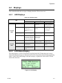
4.2.1 LED Displays .................................................................................................................................... 4-3
4.2.2 LCD Status Display .......................................................................................................................... 4-3
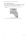
4.2.2.1 Adjusting LCD Contrast ........................................................................................................ 4-4
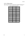
4.2.2.2 LCD Abbreviations ................................................................................................................ 4-5
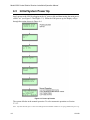
Initial System Power Up .......................................................................................................................... 4-6
Log On / Log Off ..................................................................................................................................... 4-7
4.4.1 Installer Profile ................................................................................................................................. 4-7
4.4.2 Operator Profile ................................................................................................................................ 4-7
4.4.3 Default User Codes ........................................................................................................................... 4-8
4.4.4 How to log on the system. ................................................................................................................ 4-8
4.4.5 How to log off the system. ................................................................................................................ 4-9
Modes of Operation ............................................................................................................................... 4-10
4.5.1 Normal Mode .................................................................................................................................. 4-10
4.5.1.1 Manual Operation ................................................................................................................ 4-10
How to Manually Acknowledge Calls: ....................................................................................... 4-10
4.5.1.2 Automatic Operation ............................................................................................................ 4-10
4.5.1.3 Log Only .............................................................................................................................. 4-10
4.5.2 Program Mode ................................................................................................................................ 4-10
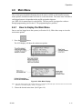
Main Menu ............................................................................................................................................. 4-11
4.6.1 How to display the Main Menu ...................................................................................................... 4-11
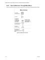
4.6.2 How to Maneuver Through Main Menu ......................................................................................... 4-12
4.6.3 Call History ..................................................................................................................................... 4-13
4.6.4 System History ................................................................................................................................ 4-13
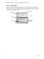
4.6.5 System Info ..................................................................................................................................... 4-14
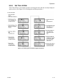
4.6.6 Set Time & Date ............................................................................................................................ 4-15
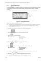
4.6.7 System Restart ................................................................................................................................ 4-16
4.6.8 Printer Menu ................................................................................................................................... 4-17
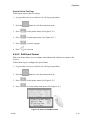
4.6.8.1 Print Report .......................................................................................................................... 4-18
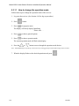
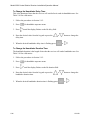
How to Print Call History ............................................................................................................ 4-18
How to Print System History ...................................................................................................... 4-19
How to Print System Configuration ............................................................................................ 4-20
How to Print a Test Page ............................................................................................................. 4-21
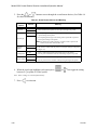
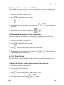
4.6.8.2 Edit Event Format ................................................................................................................ 4-21
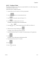
4.6.8.3 Configure Printer .................................................................................................................. 4-23
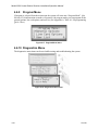
4.6.9 Program Menu ................................................................................................................................ 4-24
4.6.10 Diagnostics Menu ........................................................................................................................... 4-24
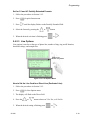
4.6.10.1 Phantom Menu ..................................................................................................................... 4-25
4.6.10.2 Message Que ........................................................................................................................ 4-26
4.6.10.3 Event Log ............................................................................................................................. 4-26
4.6.10.4 Format .................................................................................................................................. 4-27
4.6.10.5 LC Debug Mode ................................................................................................................... 4-27
4.6.10.6 LC Statistics ......................................................................................................................... 4-28
4.6.10.7 Port Status ............................................................................................................................ 4-29
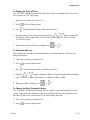
Listen-In and Hang Up ........................................................................................................................... 4-30
4.7.1 Extend (Common) Listen-In Operation .......................................................................................... 4-30
4.7.2 PBX Operation ................................................................................................................................ 4-31
Testing the System ................................................................................................................................. 4-31
151059
Content
Section 5
Programming
......................................................................................................................................... 5-1
5.1
How to Enter Program Mode ................................................................................................................... 5-1
5.1.1 Programming Fields .......................................................................................................................... 5-1
5.1.2 How to Maneuver Around in Program Mode ................................................................................... 5-2
5.2 Programming Choices .............................................................................................................................. 5-2
5.3 General Options ....................................................................................................................................... 5-3
5.3.1 Operation Mode ................................................................................................................................ 5-7
5.3.1.1 How to change the operation mode ........................................................................................ 5-8
5.3.2 Display Options ................................................................................................................................ 5-9
5.3.2.1 How to Change Language Display ...................................................................................... 5-10
5.3.2.2 How to Change Time Format Display ................................................................................. 5-11
5.3.2.3 How to Change Date Format Display .................................................................................. 5-11
5.3.2.4 How to Turn “On” or “Off” Daylight Savings. ................................................................... 5-11
5.3.2.5 How to Edit ITI Options ...................................................................................................... 5-12
5.3.2.6 How to Edit Format (FMT) Options .................................................................................... 5-13
5.3.2.7 How to Set Hold Last Event ................................................................................................ 5-13
5.3.3 Communications ............................................................................................................................. 5-14
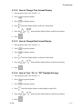
5.3.3.1 How to Set Up Port Function ............................................................................................... 5-18
5.3.3.2 How to set Com Port 1 Parameters ...................................................................................... 5-18
5.3.3.3 How to Set Com Port 2 Parameters ..................................................................................... 5-19
5.3.3.4 How to Edit Init String (Par Port) ........................................................................................ 5-20
To clear an init string: ................................................................................................................. 5-21
5.3.3.5 How to Set Automation Communication ............................................................................. 5-21
How to Set the Format ................................................................................................................ 5-21
How Enable or Disable Hex Mode ............................................................................................. 5-22
How Enable or Disable Heartbeat ............................................................................................... 5-22
Time (Period of Heartbeat) ......................................................................................................... 5-23
Ack Time (Acknowledge Time) ................................................................................................. 5-24
ITI Options (Only Visible if ITI Gen or ITIComp Formats are Chosen) ................................... 5-25
Log Recs (For ITI Formats): ....................................................................................................... 5-26
XID (Extended ID for ITI Panels): ............................................................................................. 5-26
SupCh (Supervisory Character): ................................................................................................. 5-26
NoData (No Data Character for Log Record): ............................................................................ 5-26
5.3.3.6 How to Configure the On-board Annunciator Outputs ........................................................ 5-27
5.3.3.7 How to Configure the Auxiliary Relay Outputs .................................................................. 5-28
5.3.4 System Options ............................................................................................................................... 5-29
5.3.4.1 How to Change Backup Battery Setting .............................................................................. 5-30
To Exit: ........................................................................................................................................ 5-30
5.3.4.2 How to Set the Receiver ID Number ................................................................................... 5-30
To Exit: ........................................................................................................................................ 5-30
5.3.4.3 How to Configure Output for Bad Data Blocks ................................................................... 5-31
To Exit: ........................................................................................................................................ 5-31
5.3.4.4 How to Set the Normal State of the Auxiliary Relay Contact ............................................. 5-32
5.3.4.5 Select the Receivers Clock Source ....................................................................................... 5-32
5.3.5 Message Queue Options ................................................................................................................. 5-33
5.3.5.1 Set the Message Queue Warning On level ........................................................................... 5-33
5.3.5.2 Set the Message Queue Warning Off Level ......................................................................... 5-34
5.3.5.3 Set the maximum Buffer Limit ............................................................................................ 5-34
5.4 Line Card Menu ..................................................................................................................................... 5-35
5.4.1 Add Line Card ................................................................................................................................ 5-40
151059
iii
Model 9500 Central Station Receiver Installation/Operation Manual
5.4.2 Edit Line Card ................................................................................................................................. 5-40
5.4.2.1 Handshake Sequence ............................................................................................................ 5-42
To Change the Handshake Sequence Number: ........................................................................... 5-43
To Change the Format Group: .................................................................................................... 5-43
To Change the Handshake Delay Time: ..................................................................................... 5-44
To Change the Handshake Duration Time: ................................................................................. 5-44
To Change the Maximum Handshake Wait Time: ...................................................................... 5-45
To Change the Acknowledgment Tone Duration Time: ............................................................. 5-45
5.4.2.2 Pulse Format ........................................................................................................................ 5-45
To Select Which Format a 5-digit Pulse Format will be received as: ......................................... 5-45
To Select Which Format a 6-digit Pulse Format will be received as: ......................................... 5-46
To Select the Inter-Digit: ............................................................................................................. 5-46
Set for 2300 and 1400 formats that require Acknowledges on Even Rounds: ........................... 5-46
Set for 3/1 and 4/1 Partially Extended Formats: ......................................................................... 5-47
5.4.2.3 Line Options ......................................................................................................................... 5-47
How to Set the Line Card for a Direct Line (Dedicated Line): ................................................... 5-47
To Change the Number of Rings Follow These Steps: ............................................................... 5-49
To Change the Ring On Time: .................................................................................................... 5-49
To Change the Ring Off Time: ................................................................................................... 5-50
To Select the dB Level: ............................................................................................................... 5-50
To Change the Ring Threshold Voltage: ..................................................................................... 5-50
To Change the Phone Line Sample Rate: .................................................................................... 5-51
5.4.2.4 Listen-In ............................................................................................................................... 5-52
To Change the Listen Mode: ....................................................................................................... 5-52
To Change the PBX String: ......................................................................................................... 5-53
To Change the Listen-In Timeout: .............................................................................................. 5-54
To Edit the Listen-In accounts Lists: .......................................................................................... 5-54
To Add a Listen In Account ........................................................................................................ 5-55
To Edit a Listen In Account ........................................................................................................ 5-55
To Clear a Listen In Account ...................................................................................................... 5-55
5.4.2.5 Trap List ............................................................................................................................... 5-56
To Add a Trap Account ............................................................................................................... 5-56
To Edit a Trap Account ............................................................................................................... 5-56
To Clear a Trap Account ............................................................................................................. 5-57
5.4.2.6 Misc. Line Opt. .................................................................................................................... 5-58
To Change the Echo Suppress Setting: ....................................................................................... 5-58
How to Set Caller ID ................................................................................................................... 5-59
To Change the Billing Delay Setting: ......................................................................................... 5-59
To Change the Hunt Group: ........................................................................................................ 5-60
5.4.2.7 Ademco Auto Opt ................................................................................................................ 5-60
5.4.2.8 ITI Options Menu ................................................................................................................. 5-61
ITI SCode Menu: ......................................................................................................................... 5-63
To Set Date/Time Flag: ............................................................................................................... 5-65
To Enable or Disable ITI 300 Baud Negotiation: ....................................................................... 5-65
Set the Type of Listen-In Used for ITI Controls: ........................................................................ 5-65
5.4.3 Copy Devices .................................................................................................................................. 5-66
5.4.3.1 To Program the Default Settings Into a Line Card .............................................................. 5-66
5.4.3.2 Copy the Programming of an Existing Line Card to Another ............................................. 5-66
5.4.4 Clear Device ................................................................................................................................... 5-67
To Clear or Delete a Line Card Form the Receiver Follow These Steps: ................................... 5-68
5.4.5 View Device ................................................................................................................................... 5-68
5.4.6 Rollins ............................................................................................................................................. 5-69
5.5 User List ................................................................................................................................................. 5-70
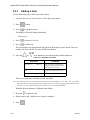
5.5.1 Adding a User ................................................................................................................................. 5-71
iv
151059
Content
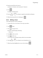
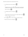
5.5.2 Editing a User ................................................................................................................................. 5-72
5.5.3 Clearing a User Out of the Receiver ............................................................................................... 5-74
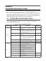
Section 6
Compatible Reporting Formats
6.1
6.2
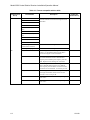
Formats By Communication Group. ........................................................................................................ 6-1
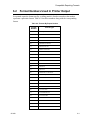
Format Numbers Used In Printer Output ................................................................................................. 6-3
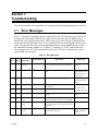
Section 7
Troubleshooting
7.1
7.2
7.3
7.4
..................................................................................... 6-1
................................................................................................................................ 7-1
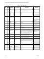
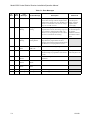
Error Messages ......................................................................................................................................... 7-1
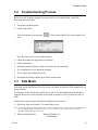
Troubleshooting Process .......................................................................................................................... 7-5
Safe Mode ................................................................................................................................................ 7-5
Updating the Receiver Software .............................................................................................................. 7-6
Section 8
Automation Communication Formats
.................................................................. 8-1
8.1
Introduction .............................................................................................................................................. 8-1
8.1.1 Conventions Observed In This Section ............................................................................................ 8-1
8.2 Silent Knight 9000 Protocol ..................................................................................................................... 8-2
8.2.1 Data String Description And Special Characters .............................................................................. 8-2
8.2.2 Calls From Panels ............................................................................................................................. 8-4
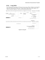
8.2.3 Long Calls ......................................................................................................................................... 8-5
8.2.4 Bad Data ........................................................................................................................................... 8-5
8.2.5 Good Data with Bad Data ................................................................................................................. 8-5
8.2.6 Validation Byte (V-Byte) .................................................................................................................. 8-6
8.2.7 System Messages .............................................................................................................................. 8-6
8.2.8 Communication from a Computer to the 9500 ................................................................................. 8-7
8.2.8.1 ACKing And NACKing Data ................................................................................................ 8-7
8.2.8.2 Link Test ................................................................................................................................ 8-8
8.3 SIA CIS (Computer Interface Standard) .................................................................................................. 8-9
8.3.1 Data String Description And Special Characters .............................................................................. 8-9
8.3.2 Basic Message Format .................................................................................................................... 8-11
8.3.3 Modifier Codes ............................................................................................................................... 8-12
8.3.4 Long Calls ....................................................................................................................................... 8-13
8.3.5 System Status Messages ................................................................................................................. 8-14
8.3.6 Heart Beat ....................................................................................................................................... 8-15
8.3.7 Communication from a Computer to the 9500 ............................................................................... 8-16
8.3.7.1 ACKing and NACKing Data ............................................................................................... 8-16
8.3.7.2 Link Test .............................................................................................................................. 8-17
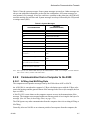
8.4 ITI Generic Computer Format ............................................................................................................... 8-18
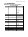
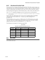
8.4.1 Convention Used In This Section ................................................................................................... 8-18
8.4.2 Report Record ................................................................................................................................. 8-18
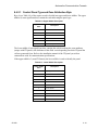
8.4.2.1 Control Panel Type and Zone Attribution Byte ................................................................... 8-19
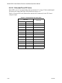
8.4.2.2 Extended Panel ID Codes .................................................................................................... 8-20
8.4.2.3 Alarm Codes ........................................................................................................................ 8-21
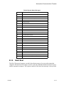
8.4.3 Log Record ..................................................................................................................................... 8-22
151059
v
Model 9500 Central Station Receiver Installation/Operation Manual
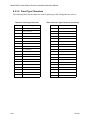
8.4.4 Test Record ..................................................................................................................................... 8-22
8.4.5 OKAY Record ................................................................................................................................ 8-23
8.4.6 ACKing and NACKing Data .......................................................................................................... 8-23
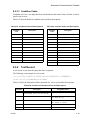
8.5 ITI Computer Interface Format .............................................................................................................. 8-24
8.5.1 Convention Used In This Section ................................................................................................... 8-24
8.5.2 General Record Structure ................................................................................................................ 8-24
8.5.3 Report Record ................................................................................................................................. 8-25
8.5.3.1 Information Field Identifiers ................................................................................................ 8-27
8.5.3.2 Panel Type Characters ......................................................................................................... 8-28
8.5.3.3 Condition Codes ................................................................................................................... 8-29
8.5.4 Test Record ..................................................................................................................................... 8-29
8.5.5 Supervisory Record ......................................................................................................................... 8-30
8.5.6 Log Records .................................................................................................................................... 8-30
8.5.7 Checksum/Control Field ................................................................................................................. 8-31
8.6 SIA 2000 ................................................................................................................................................ 8-31
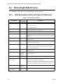
8.7 SK EXP (Silent Knight Expanded) ........................................................................................................ 8-32
8.7.1 SKE Header Block .......................................................................................................................... 8-32
Example: ...................................................................................................................................... 8-32
8.7.2 Call Message Block ........................................................................................................................ 8-33
Example: ...................................................................................................................................... 8-33
8.7.2.1 Dialer Format ....................................................................................................................... 8-34
8.7.2.2 Panel Data ............................................................................................................................ 8-35
Example: ...................................................................................................................................... 8-36
8.7.2.3 Listen-in Indicator ................................................................................................................ 8-37
Example: ...................................................................................................................................... 8-37
8.7.2.4 Trap Account Indicator ........................................................................................................ 8-38
Example: ...................................................................................................................................... 8-38
8.7.2.5 Long Call Indicator .............................................................................................................. 8-38
8.7.2.6 Bad Data Field Indicator ...................................................................................................... 8-39
Example: ...................................................................................................................................... 8-39
8.7.3 System Message Block ................................................................................................................... 8-39
Example: ...................................................................................................................................... 8-39
8.7.3.1 System Messages ................................................................................................................. 8-41
8.7.4 Heart Beat Message Block .............................................................................................................. 8-42
Example: ...................................................................................................................................... 8-42
8.7.5 Validation Byte (V-Byte) ................................................................................................................ 8-42
8.7.6 ACKing and NACKing Data .......................................................................................................... 8-43
8.7.7 Commands Initiated by the Automation Computer ........................................................................ 8-44
8.7.7.1 Remote Log-on/Log-off ....................................................................................................... 8-45
To Log-in: ................................................................................................................................... 8-45
To Log-off: .................................................................................................................................. 8-46
8.7.7.2 Force Hang-up Request ........................................................................................................ 8-46
To Force Hang-up: ...................................................................................................................... 8-46
8.7.7.3 Add or Delete a Listen-in Account ...................................................................................... 8-47
To Add a Listen-in Account: ....................................................................................................... 8-47
To Delete a Listen-in Account: ................................................................................................... 8-47
8.7.7.4 Common Listen-in Extend/End Request .............................................................................. 8-48
To Extend Listen-in: .................................................................................................................... 8-48
To End a Listen-in Session: ........................................................................................................ 8-48
8.7.7.5 PBX Listen-in String ............................................................................................................ 8-49
To Create or Edit PBX String: .................................................................................................... 8-49
8.7.7.6 Add or Delete a Trap Account ............................................................................................. 8-50
To Add a Trap Account: .............................................................................................................. 8-50
To Delete a Trap Account: .......................................................................................................... 8-50
vi
151059
Content
8.7.7.7 Link Test Request ................................................................................................................ 8-50
ADEMCO 685 Automation Protocol ..................................................................................................... 8-51
8.8.1 Low Speed 3x1, 4x1, and 4x1 Express Protocols ........................................................................... 8-51
8.8.2 Low Speed 4x2 and 4x2 Express Protocols .................................................................................... 8-51
8.8.3 Ademco High Speed Automation Protocols ................................................................................... 8-52
8.8.4 685 Contact ID ................................................................................................................................ 8-52
8.9 FBII CP-220 Automation Protocol ........................................................................................................ 8-53
8.9.1 3x1, 4x1, and 4x2 Automation Protocol ......................................................................................... 8-53
8.9.2 Acron 11 Digit with Zero or Space ................................................................................................. 8-53
8.9.3 FBII Superfast ................................................................................................................................. 8-54
8.9.4 CP-220 Contact ID® ....................................................................................................................... 8-54
8.9.5 CP-220 Silent Knight FSK Formats ............................................................................................... 8-55
8.9.5.1 Format 0 ............................................................................................................................... 8-55
8.9.5.2 Format 1 (FSK 1) ................................................................................................................. 8-55
8.9.5.3 Format 6 (FSK 2) ................................................................................................................. 8-55
8.10 US ASCII Character Code ..................................................................................................................... 8-56
8.8
151059
vii
Model 9500 Central Station Receiver Installation/Operation Manual
viii
151059
Section 1
System Overview
This manual describes installation, operation, and programming of the Model 9500 Central
Station Receiver. The 9500 is a dual line desk-top receiver. This section will list features,
optional accessories, compatible formats, and SIA options supported. This section also
contains conventions held throughout the manual, terminology relevant to this product, and
other information.
1.1
Features
Hardware:
• Supports both 120 and 240 VAC installations at 60 and 50Hz operation.
•
External annunciation with auxiliary Form C dry contact relay. (Programmable)
•
On-board PZT alert. (Programmable.)
•
1 parallel port.
•
2 serial ports.
•
2 rear SBUS connectors.
•
Modular configuration for easy replacement and repair.
•
4 line LCD Display with 20 characters for each line.
•
On-board touchpad for manual operation and programming.
•
LEDs to indicate system operations.
•
One line card will communicate with all supported formats.
•
Supports up to 2 line cards which operate independent of each other.
•
Line card parameters are stored on the MCPU for faster removal and replacement.
•
Line cards support Caller ID and Caller Name Delivery.
•
Line cards are individually programmable for format priority and ring parameters.
•
Line cards support direct connect phone line monitoring.
151059
1-1
Model 9500 Central Station Receiver Installation/Operation Manual
Software:
• Programmable display options for time and date information.
•
View or print the history information by priority or by call or by event.
•
Two user profiles to control user access to the receiver.
•
Supports up to 40 users.
•
Listen-in and trap accounts support wild card variables. Up to 20 accounts available per
line card. (20 for listen-in and 20 for trap accounts.)
•
Listen-in selectable for direct, hook flash, or PBX phone system.
•
Programmable port configuration for automation, printer and backup support.
•
500 event history buffer.
•
English or Spanish language display.
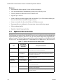
1.2
Optional Accessories
The following accessories for the Model 9500 receiver are available from Silent Knight Sales
Department unless otherwise indicated. You can contact Silent Knight Sales Department by
phone or by mail. The Sales Department’s toll free and local numbers are 800-446-6444 and
612-493-6435. Our mailing address is 7550 Meridian Circle, Maple Grove, MN 55369-4927.
Table 1-1: Optional Accessories for the 9500 receiver
Item
Description/Comments
Line card
9810
The line card monitors the phone line, detects ring and processes
the message from the communicating panel.
Backup battery
6712 (See Section 3.9
for installation.)
A 12VDC 7ah battery which will provide a minimum 4 hours of
backup power during an AC power loss. (See Section 2.3.2 for UL
backup power requirements.)
Printer cable
Not available from
Silent Knight
A standard 25-pin cable used to connect the 9500 receiver to an
external parallel printer.
UL Conduit
Connector Kit
9512 (See Section
3.8.2 for installation.)
Required to meet UL requirements for NFPA 72 Central Station
Service.
9540
Dispatcher, alarm monitoring software with report generation
(250 accounts Maximum).
9541
Dispatcher Plus, alarm monitoring software with report
generation (no account limit).
9542
Reporter, unmonitored event capture, storage and report
generation software.
Automation Software
1-2
Silent Knight
Model Number (if
applicable)
151059
System Overview
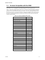
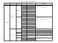
1.3
Formats Compatible with the 9500
The 9500 receiver is compatible with all Silent Knight UL listed communicators.
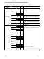
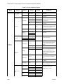
Table 1-2 shows the formats that the 9500 receiver can decode and the handshake frequency
groups which accommodate that format (see Section 5.4 for line card programming). Each
line card can decode every format listed below. Setting the handshake order only prioritizes
the type of communication done by each line card. Section 6 of this manual describes the
formats in greater detail.
Table 1-2: Formats compatible with the 9500
Format Name
BFSK
151059
Handshake
1400 or 2300 Hz
SK FSK, FSK 0, FSK 80
1400 or 2300 Hz
SK FSK 1, FSK 1, FSK 81
1400 or 2300 Hz
FSK II, FSK 86
1400 Hz
SK 4+2
1400 Hz
SK 3+1/3+1 Extended
1400 or 2300 Hz
Sescoa 3+1/Franklin 3+1
2300 Hz
Radionics 3+1 Checksum
1400 or 2300 Hz
4+1 Extended
1400 or 2300 Hz
FBI 4+3+1
1400 or 2300 Hz
SX-III, SX-IVA
2225 Hz
SX-IVB
2225 Hz
ITI SX-V
2225 Hz
ITI Commander
2225 Hz
ITI RF Commander, Harbor Gard
2225 Hz
ITI Commander 2000, LifeGard
2225 Hz
ITI CareTaker+, SecurityPro 4000
2225 Hz
ITI UltraGard
2225 Hz
SIA DCS
2225 Hz
SIA 2000 (pending approval)
2225 Hz
Ademco Contact ID
1400 and 2300 Hz
Ademco Super Fast
1400 and 2300 Hz
Acron Touch Tone
1400 and 2300 Hz
Ademco Express
1400 and 2300 Hz
DTMF 4+2
1400 and 2300 Hz
Westec
Westec
Modem II
Modem II
Modem IIe
Modem IIe
1-3
Model 9500 Central Station Receiver Installation/Operation Manual
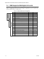
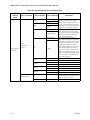
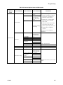
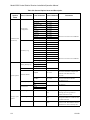
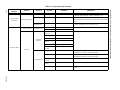
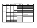
1.4
9500 Supported SIA Digital I-III Levels
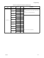
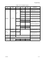
Table 1-3 compares the 9500 receiver to SIA Digital Compatibility Levels I, II, and III and
indicates which of them we comply with.
Table 1-3: 9500 and SIA Levels I-III comparison
Level III
Level II
Level I
9500
1-4
Function/Capability
Transmitter
Receiver
4
Support Tonal Acknowledgments
required
required
4
Support N blocks with Zone Numbers Only
required
required
4
Support single Account Block per Call
required
required
4
Support O Blocks
(optional)
required
4
Support X Blocks
(optional)
required
4
Support 300 Baud (Fast)
(optional)
required
Support Configuration Block
required
required
Support Data Acknowledgments
required
required
4
Support Modifier codes id, da and ti.
(optional)
required
4
Support Multiple Account Blocks per Call
(optional)
required
4
Support E Blocks
(optional)
required
4
Support Data Codes with Units Numbers
(optional)
required
Support RECEIVER call out and Access Passcode
required
required
Support Reverse Channel C Blocks
required
required
Support Reverse Channel P Blocks
required
(optional)
Support Reverse Channel A Blocks
(optional)
required
Support Dynamic block and Group Sizes
(optional)
required
4
Support Listen-in
(optional)
required
4
Support A Blocks to RECEIVER
(optional)
required
Support V-Channel communication
(optional)
(optional)
151059
System Overview
1.5
How to Use this Manual
This manual contains information on how to install, operate and program the 9500 receiver.
Silent Knight strongly suggests that the manual be reviewed in its entirety to become familiar
with procedures and parameters of the product. Once you are familiar with the product, the
manual can be used as a reference document.
The manual uses the following conventions:
•
A small graphic of each touchpad button is used to represent which touchpad key is to be
pressed for a given operation. For example, an up-arrow would be shown as:
•
LCD display
This typeface represents messages that appear on the LCD.
•
2225Hz
This typeface represents an editable field that appears on the LCD.
•
Pages of the manual are numbered by section. For example, a page numbered as “5-1” is
Page 1 of Section 5.
•
When this manual refers to default settings, it means programmable options set at the factory. Any programming after the receiver is powered up will change these setting.
1.6
Terminology
This section lists terminology that is specific to this product and their meaning.
Term
151059
Meaning
Communication Group
Silent Knight has separated the different types of communication by
handshake type. These handshake types can be assigned in a numbered order.
(See Section 6 for more details.)
Listen-in
Listen-in is the ability to listen in to what is happening real-time from the
central station to a remote location. This can help the central station operator
determine if he or she should dispatch for a particular alarm situation.
PZT
PZT is an abbreviation for a piezo alert sounder.
PIN
An abbreviation for Personal Identification Number. PINs are used to log in
and out of the receiver.
SBUS
Serial Bus interface to connect a 9500 receiver to 9510 Line cards and the
LCD display.
MCPU
Master Central Processing Unit.
Main Menu
The main menu will be displayed as either <Installer Menu> or <Operator
Menu> . However, this manual will refer to them as the main menu.
ACK
Stands for acknowledgment.
NACK
Stands for no acknowledgment.
1-5
Model 9500 Central Station Receiver Installation/Operation Manual
1.7
What’s in the Box
This section contains a list of the parts that are shipped with the 9500 receiver and a brief
description of their intended use.
Item
Quantity
P/N
Description
1
130393
Wiring harness used to connect the 9500 receiver to a
backup battery. It also provides a normally open or
normally closed output for an alert sounder.
9500 Installation &
Operation Manual
1
151059
A manual covering installation and operation
information related to the 9500 receiver.
Central Station Receiver
1
9500
The central station receiver assembly.
Line Card
1
9810
Line card for land lines.
1
120101
Tie wrap used as a strain relief on the phone cord. See
Figure 3-3 for location of strain relief tabs.
1
130071
A 7 foot long telephone cable with RJ-11 connectors.
1
119229
AC power cable used to connect the 9500 receiver to
an AC wall plug.
Alert Relay Wiring Harness
Strain Relief Tie Wrap
Telephone Cord
Power Cable
1.8
How to Contact Silent Knight
If you have a question or encounter a problem not covered in this manual, contact Silent
Knight Technical Support at 800-328-0103 (or 763-493-6455). To order parts, contact Silent
Knight Sales at 800-446-6444 (or 763-493-6435).
1-6
151059
Section 2
Agency Requirements
2.1
Telephone Requirements
If requested by the telephone company, the following information must be provided before
connecting this device to the phone lines:
A.
Manufacturer:
Silent Knight
B.
Model Number:
9500
C.
FCC Registration Number:
AC6USA-31519-AL-E
D.
Type of jack (to be installed by the telephone company):
RJ31X
Ringer equivalence:
0.1B
This device may not be connected directly to coin telephones or party line services.
This device cannot be adjusted or repaired in the field. In case of trouble with the device,
notify the installing company or Silent Knight for an RMA and then return it to:
Silent Knight Security Systems
7550 Meridian Circle
Maple Grove, MN 55369-4927
800-328-0103 or 763-493-6455
The telephone company may make changes in its facilities, equipment, or procedures that
could affect the operation of the equipment. If this happens, the telephone company will
provide advance notice to allow you to make the necessary modifications to maintain
uninterrupted service.
2.2
FCC Warning
This device complies with FCC Rules Part 68.
This device has been verified to comply with FCC Rules Part 15. Operation is subject to the
two following conditions: (1) This device may not cause radio interference, and (2) This
device must accept any interference received including interference that may cause undesired
operation.
151059
2-1
Model 9500 Central Station Receiver Installation/Operation Manual
2.3
UL Requirements
Follow the procedures outlined in the sections below for listing as an NFPA 72 Central Station
Service installation. The 9500 is also suitable for household and commercial burglary service.
Note: Installation regulations are subject to the jurisdiction of the local authority.
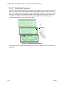
2.3.1
Hardware Requirements
1. A second 9500 must be installed as a backup in case the primary 9500 fails. The backup
system must be able to take over within 30 seconds. (Note: This requirement does not
apply to burglary-only installations.)
2. AC power must run in conduit and be attached to the 9512 conduit connector kit. See
Section 3.8.2.
2.3.2
Operational Requirements
1. The transmitters reporting to the 9500 must be UL Listed DACTs (digital alarm communicator transmitters).
2. The central station must provide a minimum of 24 hours of backup power within 30
seconds of a AC power loss. The backup must either be in the form of a UL listed UPS or
electrical generator.
3. If the 9500 is not automated, the central station operator must check for the 24 hour test
signals from the communicators. (Note: This requirement does not apply to burglary-only
installations.)
4. The connection between the 9500 and the UL listed computer should be according to the
pin configuration for Com port 1 as shown in Section 3.10, Figure 3-14 and Figure 3-15,
of this manual.
5. If a computer is used, the computer and its accessories must be installed in the same room
as the receiver.
6. The listen-in feature is intended for burglary applications only and may not be used if the
receiver will be accepting commercial fire signals.
2.3.3
Programming Requirements
In a UL listed installation, the Model 9500 receiver must be programmed according to the
following procedure:
•
•
2-2
Do NOT use the alarm output relay in UL installations.
Each log-on code must have at least four digits.
151059
Section 3
Installation
This section contains information necessary to install a 9500 Central Station Receiver.
IMPORTANT!
Do not connect power to the system until you have read these instructions carefully.
3.1
Environmental specifications
•
Temperature range is 32º to 120º F.
•
Indoor use only.
•
85 percent non-condensing humidity.
•
Non-corrosive environment.
3.2
Electrical Specifications
Line Voltage:
Fuse:
Backup Battery Connection:
Note: A 12 VDC battery
does not provide standby
time required by UL and
NFPA standards. A UPS
(listed for Protective
Signaling Use) must be
utilized when standby power
is required. See 5.3.4 for
details on backup battery
configuration.
Auxiliary Relay:
151059
120VAC ± 10%
60Hz, 100VA
240VAC ± 10%
50Hz, 100VA
2.5A Slow Blow
Input
12 VDC Nominal
3 Amp Max.
Output
13.65 VDC
1 Amp charging current
2.5 Amp @ 48VDC
Resistive
Power Limited
2.5 Amp @ 48VAC
Resistive
Power Limited
3-1
Model 9500 Central Station Receiver Installation/Operation Manual
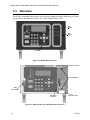
3.3
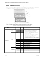
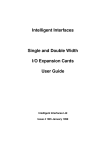
Overview
The 9500 is assembled at the factory. One line card is shipped with the 9500 receiver. Follow
the procedures described in Section 3.4 to install additional line cards.
LCD
Display
LED
Display
Touchpad
Figure 3-1 Model 9500 Front View
Inserted Line Card
Line Card Guides
Main
Power Switch
Phone Line
Connector
Phone Line Slots
Figure 3-2 Model 9500 Front View Without the Cover On
3-2
151059
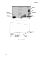
Installation
AC Power
Cord Connector
Fuse
Remote Relay
Connector
Phone Line
Strain Relief
Tie Wrap Holders
Parallel
Printer Port
Phone Line
Slot
Serial
Ports
Figure 3-3 Model 9500 Rear View
Cover Screws
(Two on each
side)
Flip Leg Down to
Raise Up Front
Figure 3-4 Side View
151059
3-3
Model 9500 Central Station Receiver Installation/Operation Manual
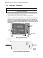
3.4
Line Card Installation
Caution:
To reduce the risk of electrical shock and damage to the receiver, follow these steps
in the order they are listed here.
1. Remove the 9500’s cover by unscrewing the four cover screws located on both sides of the
receiver. (See Figure 3-4 for the cover screw locations.)
2. Turn off the 9500’s power switch (see Figure 3-5 for power switch location).
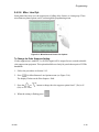
3. When the cover is removed, you will see that there are 2 slots for line cards. The receiver
recognizes each slot by number 1 and 2 (slot one is closest to the keypad and display). It is
not necessary to put line cards in numbered order because the receiver continually polls
each slot to see if existing line cards are functioning and if it is still in its slot. The receiver
also looks to see if a new line card has been added. Figure 3-5 shows where each line card
should be placed.
Line Card
Guides
On
Power
Switch
Off
Phone Line Slots
Phone Line
Connector
Figure 3-5 Line Card Locations
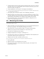
4. Position the line card as shown in Figure 3-6.
Top of Linecard
Insert From
Front of Receiver
In This Direction
Line Card
Display LEDs
Phone Line
Connector
Figure 3-6 Line Card Position and Components
3-4
151059
Installation
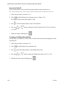
5. Carefully slide the card into its guides (both top and bottom) until it fits into its connector
at the back of the receiver. Gently push the card as far into the connector as you can. The
card is now in place. See Figure 3-5.
6. Connect telephone line. (See Section 3.6 for telephone line installation.)
Note: Use the tie wrap (P/N 120101 provided with each line card) on the tie wrap holder to add strain relief to
the telephone lines. See Figure 3-3.
7. Power up the 9500. See Section 3.8 and 3.9 for AC and battery connections.
8. Replace the 9500’s cover and screw in the cover screws to hold the cover in place. If you
are simply replacing a line card with another card of the same type and are using the same
format settings, your installation is now complete. If not continue to the next step.
9. Enter programming mode to select the appropriate handshake configuration. (Go to
Section 5.4 for programming procedure.)
3.5
Removing Line Cards
If you need to remove a card:
1. Remove the 9500’s cover by unscrewing the four cover screws located on both the sides of
the receiver. (See Figure 3-4 for front plate retaining screw locations.)
2. Turn off the 9500’s AC power switch (see Figure 3-2 for power switch location).
With the cover removed you will see that there are 2 slots for line cards.
3. Locate the Line Card that you wish to remove.
4. Unplug the telephone line. (See Figure 3-5 and Figure 3-6.)
5. From the front side of the receiver pull the line card straight back. This will pull the card
free from the connector at the rear of the receiver.
6. When the card is free, slide it carefully out of the receiver.
Note: If replacing a line card with a new one see Section 3.4 to install the new line card.
7. Power up the 9500.
8. Replace the 9500's cover and replace the cover screws.
9. Enter programming mode to clear the linecard from the system. (See Section 5.4 for
programming procedure.)
151059
3-5
Model 9500 Central Station Receiver Installation/Operation Manual
3.6
Telephone Line Connection
See Figure 3-3 for the location of the phone line inputs. Connections to the 9810 phone jacks
are made with a standard 7-foot phone cord (provided with each line card).
Use the following procedure to connect phone lines to the 9810 line cards:
1. Remove the cover of the 9500 receiver by loosening cover screws. (See Figure 3-4 for
cover screws locations.)
2. From the back side of the receiver insert the telephone line through the corresponding slot
for the desired line card. (See Figure 3-5 and Figure 3-6 for phone line slot locations.)
3. Gently push it all the way through to the front side of the receiver.
4. Plug the RJ-11 phone connector into the connector on the 9810 line card. (See Figure 3-5
and Figure 3-6.)
Note: Use the tie wrap (P/N 120101 provided with each line card) on the tie wrap holder to add strain relief to
the telephone lines. See Figure 3-3.
5. Replace the cover of the 9500 receiver. (See Figure 3-4 for cover screws locations.)
3-6
151059
Installation
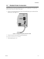
3.7
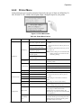
Parallel Printer Connection
The 9500 Receiver connects to model SK320 printer for UL applications. To connect the
SK320 to the 9500 receiver follow these steps:
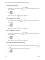
1. Connect the standard parallel printer cable to the parallel printer port on the back of the
9500 receiver. (See Figure 3-7.)
To Printer
Figure 3-7 Parallel Printer Cable Connection to 9500
2. Connect the other end to the SK320 parallel printer port.
Note: Make sure that printer power is turned off.
3. Turn the printer power “on”.
151059
3-7
Model 9500 Central Station Receiver Installation/Operation Manual
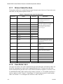
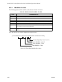
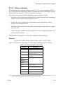
3.7.1
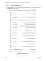
Printer Cable Pin-Outs
25 pin printer cables are a standard items at most electronic stores, however, if you create your
own cable, use the pin description in Table 3-1.
Table 3-1: External Printer Cable Pin Description
9500 Pin #
Signal
Direction
Description
1
Data Strobe (Low)
Out
A low strobe pulse to read data in the
pulse width is greater than 0.5
microseconds.
2
Data Bit 1
Out
3
Data Bit 2
Out
4
Data Bit 3
Out
These signals represent information
of the first to eighth bits of parallel
data. Each signal is at high level
when the data is logic 1 and low
when it is logic 0.
5
Data Bit 4
Out
6
Data Bit 5
Out
7
Data Bit 6
Out
8
Data Bit 7
Out
9
Data Bit 8
Out
10
/AckNlg
In
A low pulse from the printer signals
the control that the printer is ready for
additional data.
11
Busy
In
A high level indicates that the printer
is busy.
12
Paper Empty
In
A high level indicates that the printer
is out of paper.
13
Select
In
A low level indicates the printer is
offline or in an error condition.
14
Not used
-
-
15
Not used
-
-
16
Logic ground
-
Logic ground for printer
17
Not used
-
-
18 to 25
Logic Ground
-
Ground return for data lines.
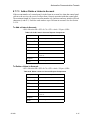
3.7.2
Com Ports 1 & 2
Com ports one and two are serial communication ports that (through a null modem cable) can
be used to communicate to other serial communication devices. Com port one is the only
serial communications port that can be used with the automation computer (see Section 3.10).
A standard null modem cable can be used to connect com port 1 or 2 to another serial device
such as a printer or a PC. Figure 3-14 and Figure 3-15 shown the pin-outs for a null modem
cable. See Section 5.3.3 to configure the Com Port 1 and Com Port 2.
3-8
151059
Installation
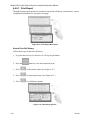
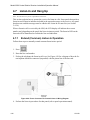
3.7.3
Remote Alert Output
1. Plug the Relay wiring harness onto the connector on the back of the 9500 receiver. (See
Figure 3-8.)
Note: The remote alert output is a form C relay with a normally open or a normally closed wire.
Figure 3-8 9500 Remote Alert Output/External Backup Battery Connection
2. Connect the white wire to common.
3. Use the Yellow wire for a normally closed circuit
Or
Use the Brown wire for a normally open circuit.
151059
3-9
Model 9500 Central Station Receiver Installation/Operation Manual
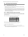
3.8
3.8.1
AC Power Cord Connection
Using Standard Power Cord
1. Before the AC power cord is connected, make sure that the power switch is in the OFF
(down) position. See Figure 3-2 and Figure 3-10.
2. Connect the appropriate end of the power cord into its receptacle on the back of the 9500.
3. Plug the three-pronged end of the power cord into a 120 VAC 60 Hz outlet (three-prong
type only). The outlet should be unswitched, so that power remains on 24 hours a day. The
outlet must also be earth grounded. Follow the directions in Section 3.8.4 if you need to
measure for proper earth grounding.
3.8.2
Using UL Listed AC Power Connection
To meet UL requirements for Central Station Service, the AC power must be run in conduit
into a single gang junction box. Use UL listed Model 9512 Conduit Connector Kit to attach
conduit to the receiver.
Table 3-2 lists the items contained in the 9512 Conduit Connector Kit.
Table 3-2: 9512 Conduit Connector Kit
Item
Quantity
Single Gang Electrical Box
1
Receiver Chassis Mounting Screws
2
AC Pigtailed Power Cable
1
Follow these steps to properly connect the AC and the 9512 connector kit:
Note: It may be necessary to have a licensed electrician make the AC connections.
1. Run AC wire in conduit to the receiver.
Warning!
To avoid electrical shock, make sure that AC power on the this circuit is turned off.
2. Feed AC wire through the conduit opening in the back (or the opening that best fits your
conduit configuration) of the single gang electrical box.
3-10
151059
Installation
3. Connect the AC wire to the Receiver AC pigtailed power cable. See Figure 3-9.
Pigtailed
Power Cable
Return
(Neutral)
Wires
Line (Hot)
Wires
Ground
Wires
AC Wire
Figure 3-9 AC Wire Connection To Receiver Pigtail
4. Plug the wired pigtail into the AC receptacle on the back of the receiver. See Figure 3-3.
5. Secure the electrical box to the back of the receiver with the two receiver chassis
mounting screws.
Receiver
Chassis
Mounting
Screw
Conduit
Coupler
Conduit
6. Connect the conduit to the electrical box using the appropriate conduit coupler.
7. Turn on AC power to this circuit.
151059
3-11
Model 9500 Central Station Receiver Installation/Operation Manual
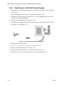
3.8.3
Switching to a 230 VAC Power Supply
1. Remove the cover by unscrewing the four cover screws. (See Figure 3-4 for locations of
cover screws.)
2. Turn the main power switch to the “off” position. (See Figure 3-10.)
3. Disconnect AC power cable. See Sections 3.8.1 or 3.8.2 depending on the type of AC
connection used in this installation.
4. Disconnect the backup battery. (See Figure 3-13.)
5. Switch the power supply select switch to the up position. The switch will show 230VAC.
(See Figure 3-10 and Figure 3-12.)
On
Off
Figure 3-10 Side View of Power Supply Assembly
6. Reconnect the AC power cable.
Note: Make sure to plug the AC power cable into a grounded 240VAC outlet.
7. Reconnect the back-up battery. (See Figure 3-13.)
8. Turn the main power switch to the “on” position. (See Figure 3-10.)
9. Replace the cover by screwing in the four cover screws. (See Figure 3-4.)
3-12
151059
Installation
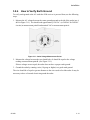
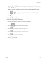
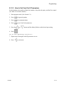
3.8.4
How to Verify Earth Ground
To verify earth ground at the AC outlet the 9500 receiver is powered from, use the following
steps:
1. Measure the AC voltage between the center ground post and each side of the outlet (see A
& B in Figure 3-11). You should read approximately 120 VAC (or 240VAC for 240VAC
circuits) at measurement point B and nominal VAC at measurement point A.
Figure 3-11 Outlet Voltage Measurement Points
2. Measure the voltage between the two slotted holes. It should be equal to the voltage
reading at measurement point B. (See Figure 3-11.)
If these voltages are not equal, the outlet does not have a proper earth ground.
3. Ground the outlet by running a wire (18 gauge or higher) to a good earth ground.
The wire should be of equal or greater diameter to the wires used to feed the outlet. It may be
necessary to have a licensed electrician ground the outlet.
151059
3-13
Model 9500 Central Station Receiver Installation/Operation Manual
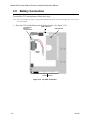
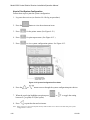
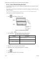
3.9
Battery Connection
To install the 6712 backup battery follow these steps:
Note: The 6712 (12VDC 7ah battery) will provide a minimum of 4 hours of battery backup power. (See 2.3.2 for
UL requirements.)
1. Place the 6712 backup battery into the battery bucket. (See Figure 3-12.)
Back of Receiver
Power Supply
230/115 V
Selector Switch
Battery Bucket
Battery
Leads
-
+
Front of Receiver
Figure 3-12 Top View of Receiver
3-14
151059
Installation
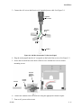
2. Connect the RED terminal to the positive (+) side of the battery.
Figure 3-13 Battery Connections
3. Connect the BLACK terminal to the negative (-) side of the battery.
Note: Incorrect polarity can damage the battery and the 9500.
151059
3-15
Model 9500 Central Station Receiver Installation/Operation Manual
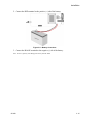
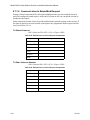
3.10 Automation Computer Connection
An automation computer can be connected to Com Port 1 on the 9500 receiver. Com Port 1 is
a 9-pin DTE port. Refer to Section 8 for details on automation communication protocols. The
diagrams below describe some of the cable options.
Figure 3-14 25-Pin Null Modem Cable Connection
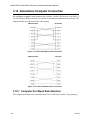
Figure 3-15 9-Pin Null Modem Cable Connection
3.10.1 Computer Port Baud Rate Selection
The computer port baud rate is selectable from 110 to 19200 (See Section 5 Programming).
3-16
151059
Section 4
Operation
This section covers information on how to operate the 9500 Receiver.
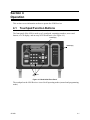
4.1
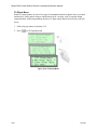
Touchpad Function Buttons
The front panel of the 9500 is made up of; a touchpad, containing numbers, arrows and
buttons; a LCD display; and an array of LED indicators. (See Figure 4-1.)
LCD Display
LED Display
Touchpad
Keys
Figure 4-1 Model 9500 Front Panel
The touchpad on the 9500 Receiver is used in all operating modes (normal and programming
mode).
151059
4-1
Model 9500 Central Station Receiver Installation/Operation Manual
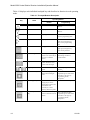
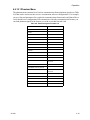
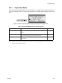
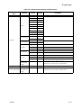
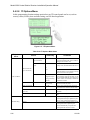
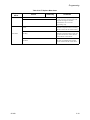
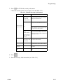
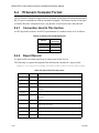
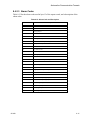
Table 4-1 displays each individual touchpad key and describes its function in each operating
mode.
Table 4-1: Touchpad Buttons Description
Operating Modes
Key
Name
Normal
Up Arrow
Display previous event.
Go back to previous choice or
character.
Down Arrow
Display next event.
Move to next choice or
character.
Left Arrow
Display previous call.
Exit the current menu. Move to
previous programming field.
Right Arrow
Display next call.
Select menu item indicated by
equal sign (see Figure 4-5).
Move to next programming
field.
Enter/Menu Button
Bring up Main Menu.
Select menu item indicated by
equal sign (see Figure 4-5).
Enter chosen parameter.
Acknowledge Button
Manually Acknowledge a
call or event. (Used only if
receiver is in manual
mode.)
Used in log mode to
acknowledge and silence
system troubles.
Log Button
Pressed to log on or off the
system. Pressed to view
system status messages.
N/A
Digit Keys
Used to enter numeric
inputs.
Numeric input, option
selection.
Star or Home Key
Will return display to the
oldest unacknowledged
event.
Enters a * Character when
programming in an “Edit” field.
See Table 5-1 for Types of
Programming Fields,
descriptions.
0 or Hangup key
In manual mode the 0/
hangup key is used to
hangup line card when the
listen feature was
activated, or to end a
runaway call from a panel.
Used to enter numeric inputs.
Pound Key or Listen
Key
In manual mode this key is
used to initiate the listen in
feature.
Enters a # Character when
programming in an “Edit” field.
See Table 5-1 for Types of
Programming Fields,
descriptions.
-
4-2
Programming
151059
Operation
4.2
Displays
This section describes the two types of displays that the 9500 receiver uses.
4.2.1
LED Displays
Table 4-2: LED Description
Meaning
LED
On
AC Power
System Fault
Touchpad
LEDs
Operator Logged In
AC power is on.
No AC or DC power to
the Receiver
No AC power and the
system is operating on
the backup battery.
A fault condition exists
that has been
acknowledged but not
cleared.
The system is operating
normally.
A fault condition exists
that has not been
acknowledged.
An operator is logged on. No operator is logged
on.
No calls pending or all
calls have been
acknowledged.
Calls pending.
N/A
The line card is
operating normally.
Trouble or fault
condition exists.
Active (Green)
The line card is in active
communication.
No Activity.
Indicates the line is
ringing.
Listen (Amber)
Comes on when operator
acknowledges the listenin call.
No listen-in occurring.
N/A
Fault (Red)
4.2.2
Flashing
The acknowledge key
was pressed at least once,
but not all the events in a
call were acknowledged.
Call Pending
Line Card
LEDs
Off
LCD Status Display
The status display is a 4-line 20 character (each line) back-lit LCD that shows the various
alarm and function messages. It functions in all modes of operation (normal and programming
mode). As the 9500 acknowledges calls and messages, it updates the calls on the LCD and
silences the alert tone.
Figure 4-2 LCD Display
151059
4-3
Model 9500 Central Station Receiver Installation/Operation Manual
4.2.2.1 Adjusting LCD Contrast
The LCD is factory set at the highest contrast level and for most installations will not need to
be adjusted. Use these steps to change the LCD contrast if the brightness of the room or the
location in which the receiver is located should require a contrast change:
1. Press and hold both the up arrow and the left arrow keys at the same time. (See
Figure 4-3.)
Figure 4-3 Contrast Adjustment
2. Release the up and left arrow keys when you reach the desired contrast level.
4-4
151059
Operation
4.2.2.2 LCD Abbreviations
Many of the words used on the LCD are abbreviated to accommodate 20 characters per line.
Table 4-3 compares the event that is reported to how it is output to the LCD and printer.
Table 4-3: LCD and Printer Abbreviations
Event
151059
LCD
Printer
Alarm
Alrm
Alarm
Trouble
Trbl
Trouble
Restore
Rstr
Restore
Supervisory
Sprv
Superv
Opening
Open
Opening
Closing
Clos
Close
Remote
Rmot
Remote
Disable
Dsbl
Disable
Bypass
Byps
Bypass
Unbypass
Ubyp
Unbypass
Test
Test
Test
Listen-in
Lstn
Listen
System
Sytm
System
Access
Accs
Access
Report
Rprt
Report
Cancel
Cncl
Cancel
Zone Number
Z#
Zone
Door Number
D#
Door
User Number
Us#
User
Area Number
A#
Area
4-5
Model 9500 Central Station Receiver Installation/Operation Manual
4.3
Initial System Power Up
Apply power to the 9500 by plugging in the AC power cable and then turning the main power
switch “on” (see Figure 3-2 and Figure 3-3). When the 9500 powers up, the display will go
through the routine shown in Figure 4-4.
Figure 4-4 Power-up Routine
The system defaults in the manual operation. To select automatic operation see Section
5.3.1.1.
Note: Any time the main power switch is turned off the time and date will have to be reprogrammed on power-up.
4-6
151059
Operation
4.4
Log On / Log Off
Persons operating the 9500 must log on and off the system. This is a way of keeping track of
whom is operating the system at any given time.You can program a total of 40 codes. Each
code will be assigned to one of two user profiles (Installer profile or Operator profile). (See
Section 4.4.3 for default user codes.)
4.4.1
Installer Profile
The Installer profile will have access to all options on the main menu (see Table 4-4 for “Main
Menu” options).
4.4.2
Operator Profile
The Operator profile has access to fewer main menu options than the Installer profile (see
Table 4-4). These options allow the operator to perform basic operation of the 9500. Both
profiles can acknowledge all calls and events.
Table 4-4: Main Menu Option Items by Profile
Installer
Profile
Operator
Profile
4
4
Call History
4
4
System History
4
4
System Info
4
4
Set Time & Date
4
4
System Restart
Menu Options
4
Printer Menu
4
Program Menu
4
Diagnostics
Note: See Section 4.6 for detailed information on the main menu options.
You must have at least one Installer Profile Code programmed in the system at all times.
151059
4-7
Model 9500 Central Station Receiver Installation/Operation Manual
4.4.3
Default User Codes
At initial power up, the system provides two default user codes. User code 1 defaults with an
Installer profile and user code 2 defaults with an Operator profile. Table 4-5 shows the default
codes and their profiles.
Table 4-5: Default User Codes
User Number
Default Code
(PIN)
*1
9500
Installer
2
1111
Operator
Default Profile
* Note: User code 1 can be changed but not deleted. User code 1’s profile will always remain as “installer”.
4.4.4
How to log on the system.
Follows these steps to properly log on to the system:
1. Press the
button.
The LCD will display Enter Log In Code:
[]
2. Enter your PIN code. (See Table 4-5 for default codes.)
Note: This screen will time out after 15 seconds.
3. Press the
button.
If the correct PIN is entered the LCD will display Installer # XX
User Name.
The “Operator Logged In” LED will also turn on.
If an invalid code is entered the LCD will display Access code not verified.
Note: If the previous user has not logged off, a new user can still log on by entering a PIN code. This will
automatically log off the previous user and log in the new user.
4-8
151059
Operation
4.4.5
How to log off the system.
Follows these steps to properly log off the system:
1. Press the
button.
The LCD will display
#nn User Name
Log Out
[]
Note: This screen will time out after 15 seconds.
2. Enter your PIN code. (See Table 4-5 for default codes.)
3. Press the
button.
If the correct PIN is entered the LCD will display User Name Logged out . The “Operator
Logged In” LED will also turn off.
If an invalid code is entered the LCD will display Access code not verified.
151059
4-9
Model 9500 Central Station Receiver Installation/Operation Manual
4.5
Modes of Operation
This section describes the different modes of operation for the 9500 Receiver (normal mode
and programming mode) and the options available in them.
4.5.1
Normal Mode
Normal mode consists of three options, one if the receiver is intended to be used with a
automation system, one for manual operation, and one to just log the events without manual
acknowledgments or automation communication.
4.5.1.1 Manual Operation
Requires a manual acknowledgment of each call or event from an operator.
How to Manually Acknowledge Calls:
When a the call pending LED is flashing and the on-board annunciator is beeping:
1. Press the
button to acknowledge the call.
2. Repeat step 1 until all calls are acknowledged and the display shows No More Data.
4.5.1.2 Automatic Operation
Event information is sent directly to the automation computer.
Note: If the automation system fails, the receiver will automatically switch to manual mode in less than 30
seconds. The switching time is twice the value set in Ack Timeout (See Table 5-5). The receiver will return
to automatic mode after communication to the automation computer is restored.
4.5.1.3 Log Only
Log only mode will log event data without manual acknowledgments or communications with
the automation computer. All event information is intended for printer output.
Note: On initial power-up the receiver will default in manual operation. The receiver can be set to automatic or
log only operation in program mode (see Section 5.3.1).
4.5.2
Program Mode
In program mode all general, line card, and user profile options can be changed. See Section 5
Programming for more detailed information on programming the receiver or refer to the
Quick Chart (, Table A-1) for programming overview.
4-10
151059
Operation
4.6
Main Menu
This section gives detailed information about the items available in the Installer/operator
menu options, which this manual will refer to as the main menu. The menu items available to
each logged on user is dependent on the profile assigned to that user
(see Table 4-4 for menu items for each profile). The user profile is assigned to each user
through programming (see Section 5.5 for programming user profiles).
4.6.1
How to display the Main Menu
Once a user has logged on to the system (see Section 4.4.4), follow these steps to view the
main menu options:
1. Press the
button.
The LCD display will show the main menu options.
Figure 4-5 Main Menu Display
Note: The main menu display will remain visible for 15 minutes of idle time after which it will revert back to the
manual or automatic display window. See Figure 4-2.
2. Choose the desired menu item. (See Figure 4-6.)
151059
4-11
Model 9500 Central Station Receiver Installation/Operation Manual
4.6.2
How to Maneuver Through Main Menu
Figure 4-6 indicates what keys on the touchpad are used to maneuver through the Main Menu.
Figure 4-6 Main Menu Controls
4-12
151059
Operation
4.6.3
Call History
Call history displays the calls that are in the history buffer.
Line Card No.
Event Reference
No. (0001-9999)
Account Number
(Up to Eight Digits)
Reason for Call
Number and order
of events for this
report
Zone Number
Month &
Day
Time
Star indicates that
the call was acknowledged
Figure 4-7 View of a Call History Screen
Note: The Letter preceding the linecard number may appear as a “G” if the linecard the call came in on is
programmed for a hunt group. See “Misc. Line Opt.” in Section 5.4.2.6.
To display a specific event enter the reference number then press the
to go to most recent call. See Table 4-3 for display abbreviations.
4.6.4
. Press the
System History
System history displays any events that are stored in the history buffer. System events are any
events related to the receiver operation such as line card faults, low backup battery, AC power
loss, log in, log out, system program change, communication failure to a printer or automation
system, etc.
Event Number
View after
2 pressed
Up arrow
displays previous
event
Figure 4-8 System History Display Sequence
Note: Up arrow moves back to the previous event that occurred.
To display a specific event enter the event number (see Figure 4-8) then press the
the
151059
. Press
to go to most recent call.
4-13
Model 9500 Central Station Receiver Installation/Operation Manual
4.6.5
System Info
System Info is a non-editable screen that displays the model number, the software revision,
software date code, receiver ID number. If a down arrow is pressed, the display will show the
line card firmware information, which includes the model number, the software revision, the
software date code, and letter revision.
Version Number
Model Number
Date Code
Firmware
Part Number
Letter Rev.
Figure 4-9 System Information Display
4-14
151059
Operation
4.6.6
Set Time & Date
If Set Time & Date, is selected the operator can change the time and date currently displayed
on the receiver. (See Figure 4-10 for setting time and date procedure.)
Figure 4-10 Setting Time and Date Program Sequence
151059
4-15
Model 9500 Central Station Receiver Installation/Operation Manual
4.6.7
System Restart
System restart allows the operator or installer to restart the receiver. An installer has the option
to set the receiver back to factory default settings, while an operator can only restart the
receiver.
Note: The time and date set in the receiver will be saved. However, all of the call history will be lost
Figure 4-11 System Restart Display
Follow These Steps to restart the receiver:
Note: All messages must be acknowledged before a system restart procedure can be performed. If all messages
are not acknowledged, cycle the receiver’s power to restart the system. If the power is cycled all
unacknowledged messages will be lost.
1. Log on to the receiver (see Section 4.4.4 for log on procedure).
2. Press the
3. Press
button to view the main menu items.
5
for System Restart.
The display reads
4. Press the
5. Press
or
Do you wish to
shutdown & restart
system?No
button to toggle No to Yes.
. Users with an operator profile are done at this point.
The display reads
Do you wish to set
to factory default
settings?No
Note: This display will only appear if the logged on User has an Installer Profile (see section 4.4.1).
6. Press the
or
button to toggle between No and Yes.
Note: If you choose Yes all linecard and user custom programming will be lost.
4-16
151059
Operation
4.6.8
Printer Menu
In the print menu you can print customized reports by the type of alarm (as defined by UL
864, Section 72.15F), edit the desired print output, configure output for your printer.
Figure 4-12 Print Menu Items
Table 4-6: Printer Menu Choices
Printer Menu
Choice 1
Choice 2
Comments
Priority 1
Y
(Life safety signals-Fire, Duress)
Call History
Priority 2
(Property safety signals-Burg.)
N
Priority 3
(Supervisory signals)
The call History print will execute once you exit
from “Choice 2”.
Priority 4
(Trouble signals)
Print Report
System Config
Note: Choice 2 settings are not retained in flash
memory and have to be chosen for each
call history printing.
This option prints all the system events in the
event history buffer.
Print All
Print all of the receiver and line card data.
Program Data
Print just the systems programmed data.
Line Card #
Print line card configurations per line card.
Test Page
Print a test page.
Date
Y or N
Y
Indicates that this item will print on a report.
Format Type
Y or N
N
Ref Number
Y or N
Indicates that this item will not print on a
report.
Call Sep
Y or N
Default setting is Y for all edit event format
options.
Device Num
Y or N
These settings are saved to flash memory.
Line
Terminator
CR or CRLF
CR = Carriage return.
CRLF = Carriage return and Line feed.
0 - 60 seconds
Offline time is how long the receiver will wait
before giving a trouble indication after
communication is lost with the printer. The
default setting is 2 seconds. (30 second maximum
for UL applications.)
0 - 60 seconds
Switch delay time is the duration the receiver will
wait before switching to the backup printer after
communication is lost with the primary printer.
The default setting is 20 seconds.
Offline Time
Config Printer
Switch Delay
Time
151059
Indicates that this item will not print on this
report.
Priority 5
(All other signals)
System History
Edit Evnt Format
Indicates that this item will print on this
report.
4-17
Model 9500 Central Station Receiver Installation/Operation Manual
4.6.8.1 Print Report
Through the print report option you can choose to print the call history, system history, system
configuration information, or just print a test page.
Figure 4-13 Print Report Menu Items
How to Print Call History
Follow these steps to print the call history:
1. Log on to the receiver (see Section 4.4.4 for log on procedure).
2. Press the
button to view the main menu items.
3. Press
6
for the printer menu. (See Figure 4-12.)
4. Press
1
for print report menu. (See Figure 4-13.)
5. Press
1
for call history options.
Figure 4-14 Call History Options
4-18
151059
Operation
6. Press the
4-14.
or
button to move through the call history menu choices. See Figure
7. When the equal sign highlights the call history items you desire to print for this report
press
or
8. Press
to toggle the setting between Y (yes print) or N (don’t print).
to exit menu.
How to Print System History
Follow these steps to print the system history:
1. Log on to the receiver (see Section 4.4.4 for log on procedure).
2. Press the
button to view the main menu items.
3. Press
6
for the printer menu. (See Figure 4-12.)
4. Press
1
for print report menu. (See Figure 4-13.)
5. Press
2
to print the system history.
6. Press
151059
to exit menu.
4-19
Model 9500 Central Station Receiver Installation/Operation Manual
How to Print System Configuration
Follow these steps to print the system configuration:
1. Log on to the receiver (see Section 4.4.4 for log on procedure).
2. Press the
button to view the main menu items.
3. Press
6
for the printer menu. (See Figure 4-12.)
4. Press
1
for print report menu. (See Figure 4-13.)
5. Press
3
to view system configuration options. See Figure 4-15.
Figure 4-15 System Configuration Print Items
6. Press the
or
button to move through the system configuration print choices.
7. When the equal sign highlights an option press
between Y (yes print) or N (don’t print).
8. Press
or
to toggle the setting
to print the data and exit menu.
Note: These choices are not saved to flash memory and will have to be chosen each time that print system
configuration is entered.
4-20
151059
Operation
How to Print a Test Page
Follow these steps to print a test page:
1. Log on to the receiver (see Section 4.4.4 for log on procedure).
2. Press the
button to view the main menu items.
3. Press
6
for the printer menu. (See Figure 4-12.)
4. Press
1
for print report menu. (See Figure 4-13.)
5. Press
4
to print a test page.
6. Press
to exit menu.
4.6.8.2 Edit Event Format
Edit event format allows you to configure what information will print on reports to the
receiver.
Follow these steps to configure the report format:
1. Log on to the receiver (see Section 4.4.4 for log on procedure).
2. Press the
button to view the main menu items.
3. Press
6
for the printer menu. (See Figure 4-12.)
4. Press
2
for event format menu items. (See Figure 4-16.)
Figure 4-16 Event Format Menu Items
151059
4-21
Model 9500 Central Station Receiver Installation/Operation Manual
5. Press the
or
for choice definitions)
button to move through the event format choices. (See Table 4-6
Table 4-7: Event Format Choices and Meaning
Event Format
Options
Choices
Y (Yes)
Date/Time
N (No)
Y (Yes)
N (No)
Meaning
Y = date and time will print for each report message to the printer.
N = Date and time will not print for each report message to the printer.
Y = The reporting format type of the calling control panel will print for each
report message to the printer.
N = The reporting format type of the calling control panel will not print for
each report message to the printer.
Format Type
Note: The Format Type will be listed as a number, which represents the
format used for that communication. See
Reference
Number
Call Separator
Device Number
Y (Yes)
N (No)
Y (Yes)
N (No)
Y = The reference number will print for each report message to the printer.
N = the reference number will not print for each report message to the printer.
(See Figure 4-7)
Y = Print a dashed-line between each message report to the printer.
N = Do not print a dashed-line between each message report to the printer.
Y (Yes)
Y = Print the device number of the reporting message to the printer.
N (No)
N = Do not print the device number of the reporting message to the printer.
6. When the equal sign highlights each option press
between Y (yes print) or N (don’t print).
or
to toggle the setting
Note: These settings are saved to flash memory.
7. Press
4-22
to exit menu.
151059
Operation
4.6.8.3 Configure Printer
Depending on the printer you are using it may require that this be set to either carriage return
or carriage return with a line feed.
Follow these steps to configure the printer:
1. Log on to the receiver (see Section 4.4.4 for log on procedure).
2. Press the
button to view the main menu items.
3. Press
6
for the printer menu. (See Figure 4-12.)
4. Press
3
for configure printer menu items.
The display will be flashing on the line terminator field.
5. Press the
or
button to toggle between CR or CRLF. (See Table 4-6.)
6. When the desired setting is flashing press
.
The display will now flash on the offline time field.
7. Enter the desired time (from 01-99 seconds), 30 second maximum in UL applications.
8. Press
.
The display will now flash on the switch delay time field.
9. Enter the desired time (from 01-99 seconds).
10. Press
11. Press
151059
.
to exit menu.
4-23
Model 9500 Central Station Receiver Installation/Operation Manual
4.6.9
Program Menu
If program is selected from the main menu the system will enter into “Program Mode”. (See
Section 4.5 for information on modes of operation.) In program mode you can program all the
general options, line card options, and user list. (See Appendix A, Table A-1 for programming
Quick Chart.)
Figure 4-17 Program Menu Items
4.6.10 Diagnostics Menu
The diagnostics menu items can be used while testing and troubleshooting the system.
Figure 4-18 Diagnostics Menu Items
4-24
151059
Operation
4.6.10.1 Phantom Menu
The phantom menu contains list of various communication format phantom signals (see Table
4-8) that can be used to test the receiver or automation software configurations. For example,
you set a linecard parameters for a particular communications format and would know like to
verify that this new configuration will communicate with other communication formats, you
can send phantom signals in the formats you wish to test that linecard with.
Table 4-8: Phantom Signals Formats List
Choice
151059
Format
01 DCS
DCS
02 CID
Contact ID
03 ITI
ITI format
04 BFSK
BFSK
05 A31 Task 1
3/1 format
06 A31 Checksum
3/1 format w/checksum
07 A41
4/1 format
08 A42
4/2 format
09 FSK0
FSK0
10 FSK1
FSK1
11 FSK2
FSK2
12 SIA D1
SIA D1
13 ADM42 Checksum
Ademco 4/2 format w/
checksum
14 SIA D1 Checksum
SIA D1 w/checksum
15 ACRON TOUCH TONE
Acron Touch Tone
16 ADM41 Checksum
Ademco 4/1 format w/
checksum
17 FBI 4+3+1
FBI 4+3+1
18 MeterMinder
ITI MeterMinder format
19 Modem IIE
Modem IIe format
20 SIA-2000
SIA 2000 format
21 VEMS
VEMS format
4-25
Model 9500 Central Station Receiver Installation/Operation Manual
4.6.10.2 Message Que
Message Que gives a visual indication of how full is the message queue. It does this with both
a percentage indication and a bar graph (made of *’s). Each * is approximately 5%.
Figure 4-19 Message Queue Level
4.6.10.3 Event Log
Event Log allows you to print out a certain range of reference numbers to the port designated
to diagnostics. This can be used to as a troubleshooting tool while correlating alarm messages
from the receiver to the automation computer.
Enter the reference
number you wish to
start at here.
And the range of
event here.
Figure 4-20 Event Log Display
For example, if the automation computer indicated a report that you are not familiar with, you
would enter the reference number for that report in the event log and the raw data would be
output to the diagnostic port. From the raw data you could determine what the signal was and
make adjustment to the automation computer for future signals like that one.
4-26
151059
Operation
4.6.10.4 Format
Format designates the type of output you wish for the Event Log report. The output format can
be in raw ASCII, a printer format, or one of the receivers automation communication formats
(see Section 8 for automation protocols).
Information after the dash
indicated the format
presently chosen.
Figure 4-21 Diagnostic Formats
4.6.10.5 LC Debug Mode
LC debug enables the receiver to generate detailed history of handshake sequences to the call
buffer. This information can be used for troubleshooting.
Select Line Card
Numbers
Figure 4-22 Select LC Debug Mode by Line Card
Use the
Press
151059
right arrow or
to toggle the line card selection between “Yes” or “No”.
to exit and “Yes” to save changes.
4-27
Model 9500 Central Station Receiver Installation/Operation Manual
4.6.10.6 LC Statistics
LC (Line Card) statistics allows you to view the call statistics of a specific line card in
comparison to the total number of call received.
Figure 4-23 Line Card Statistics Display
To view a line cards call statistics, follow these steps:
1. From the installer menu (See Section 4.4) press
2. Select
6
8
for Diagnostic menu.
for LC Statistics. See Figure 4-23.
3. Select the number of the line card you wish to view. See Figure 4-23.
4. Press
4-28
left arrow to exit.
151059
Operation
4.6.10.7 Port Status
Port status allows you to view the current status of any of the communication ports.
To view the status of one of the communication ports, follow these steps:
1. From the installer menu (See Section 4.4) press
2. Select
7
8
for Diagnostic menu.
for Port Status..
Figure 4-24 Port Status View of Serial Port
3. Select the communication port you wish to view. See Figure 4-24 and Figure 4-25.
Figure 4-25 Parallel Port Status View
Table 4-9: Abbreviation Display Character Meanings/High Low Status
Abbreviated Character
Meaning
↑ (Bit High)
↓ (Bit Low)
Serial Port (Com 1 & Com 2)
DSR
Data Set Ready
Ready
Not Ready
DTR
Data Terminal Ready
Ready
Not Ready
CTS
Clear to Send
Ready
Not Ready
RTS
Request to Send
Ready
Not Ready
B
Receive Break
Received Break
Ready
F
Framing Error
Framing Error
Ready
P
Parity Error
Parity Error
Ready
O
Overrun Error
Overrun Error
Ready
printer on-line status.
Printer On-line
Printer Off-line
READY
Printer ready status
Printer ready
Printer not ready
PAPER
Paper status
Paper status OK
Out of paper
Parallel Port
LINE
4. Press
151059
left arrow to exit.
4-29
Model 9500 Central Station Receiver Installation/Operation Manual
4.7
Listen-In and Hang Up
Note: See Section 2.3.2 for UL requirement on listen-in.
This section explains how to operate the receiver for listen-in calls. Some panels that perform
listen-in send a listen-in indicator included in the reported message to the receiver. Any panel
that does not send this message must be added to the Listen-In Account List (see Section
5.4.2.4).
When a listen-in call is received by the 9500, the LCD display will indicate the account
number and (depending on the panel) the listen-in timeout period. The listen-in LED on the
linecard will be illuminated to confirm the line card indication.
4.7.1
Extend (Common) Listen-In Operation
Follow these steps to manually extend common listen-in time period:
1. Press
.
2. Enter the line card number.
3. Pick up the telephone the listen-in call is on. See Figure 4-26 for a diagram of how the listen-in phone should be connected (in parallel) with the phone line of the line card.
Figure 4-26 Phone Connector Pin-Out and Listen-in Wiring Diagram
4. Perform the listen-in procedures for that panel (refer to panel operation manual).
4-30
151059
Operation
4.7.2
PBX Operation
Prior to performing listen-in functions on a PBX phone line system the receiver must be set up
with the proper listen-in mode and PBX string. Refer to Sections 5.1 and 5.4.2.4 to properly
program the receiver to handle PBX listen-in calls.
4.8
Testing the System
IMPORTANT:
The 9500 should be tested regularly to ensure complete and proper operation.
Because there are so many variations in dialer parameters and phone line conditions, the only
way to be absolutely certain that all subscribers can communicate with the 9500 is to test
every subscriber’s dialer individually. Subscribers must test their communicators every 30
days to make sure the 9500 receives the information.
When you install a new 9500, test every manufacturers’ panels for each format. This is
necessary because different manufacturers’ panels may operate differently even if all panels
use the same format.
151059
4-31
Model 9500 Central Station Receiver Installation/Operation Manual
4-32
151059
Section 5
Programming
This section lists the programmable features in programming mode and the procedures for
each of them. The options available are general options, line card options, and user options.
5.1
How to Enter Program Mode
Follow these steps to enter into program mode:
1. Log on to the receiver (see Section 4.4.4 for log on procedure).
2. Press the
3. Press the
button.
7
button.
The display will briefly displayInitializing
Please wait . . .
4. Select the option you wish to program. (See Section 5.2 for options.)
5.1.1
Programming Fields
In program mode there are three types of programming fields that data can be entered into.
Table 5-1 list the three types of fields and the various parameters associated with them.
Table 5-1: Types of Programming Fields
Type of Field
Control Keys
Comments
These fields require a numeric entry
only.
through
Numeric
or
List
keys
keys
Enter a number from the numeric
keypad or enter any special characters
by pressing the up or down arrow keys.
through
Edit
or
151059
Predefined choices are put in a list and
can be selected by pressing the up or
down arrow keys.
keys
5-1
Model 9500 Central Station Receiver Installation/Operation Manual
5.1.2
How to Maneuver Around in Program Mode
Figure 5-1 shows what keys on the touchpad are used to maneuver in program mode.
Figure 5-1 Programming Controls
5.2
Programming Choices
In programming mode your first set of choices are general options, line card options, and user
list. (Each of these choices will be described in greater detail in the following sections.) Figure
5-2 shows what the display will look like before and after the down arrow is pressed.
Figure 5-2 Program Menu Choices
5-2
151059
Programming
5.3
General Options
The features available for programming under general options are operation mode, display
options, communications, and system options.
Figure 5-3 General Options Display
Table 5-2 list the available choices under General Options and gives a description of those
choices.
Table 5-2: General Options Items and Description
General
Options
Items
Operation Mode
Level 1 Choices
Level 2 Choices
Level 3 Choices
Manual
Automatic
Log Only
Language
See Section 5.3.1 for additional
information on Operation Modes.
English
español
AM/PM
See 5.3.2.1.
AM/PM is used for 12 hour time clock
displays. See 5.3.2.2.
Time Format
Date Format
Daylight Savings
Display Options
24 Hour
M/D/Y
D·M·Y
Y-M-D
Yes
No
Attempts
CPU Time
ITI (Edit Options)
CPU Type
Panel Rev
Arming Level
151059
Comments
M = month, D = day, and Y = year.
See 5.3.2.3.
See 5.3.2.4.
Yes
No
Yes
No
Yes
No
Yes
No
Yes
No
Affects printer output for ITI calls
only.
5-3
Model 9500 Central Station Receiver Installation/Operation Manual
Table 5-2: General Options Items and Description
General
Options
Items
Level 1 Choices
Level 2 Choices
FSK1
BFSK
Level 3 Choices
Code
English (default)
Code
English
Code
SIA
English (default)
Code (default)
Display Options
(continued)
FMT
(Edit Format
options)
CID
PULSE
SK9000
ACRON
HIPSEED
Hold Last Event
Yes
English
Comments
If “English” is selected then the printer
and LCD output for calls of these
formats will be text descriptions. If
“Code” is selected then the printer and
LCD output for calls of these formats
will be the Code and Zone numbers.
If “English” is selected, the printer and
LCD output will be text. If “Code” is
selected then the printer and LCD will
display the SIA codes followed by
zone or other information.
This option only affects the SK
Expanded automation protocol output.
If “English” is selected each event will
be sent to the automation as two SIA
events; the first with the two digit
Group number and the second with the
three digit ID number. If “Code” is
selected, each event is sent as eleven
digits; two digits Message type, onedigit Event Qualifier, three-digit Event
Code, two-digit Group Number, and
three-digit ID number.
0 .. 9
0 .. F
Packed
Unpacked
Zero
Space
SIA
HiSpeed
LCD will display the last or oldest
unacknowledged event instead of the
date/time display. See 5.3.2.7.
No
5-4
151059
Programming
Table 5-2: General Options Items and Description
General
Options
Items
Level 1 Choices
Level 2 Choices
Com1
Com2
Par
Port Functions
Level 3 Choices
Unused/Automation/ Rules for Port Configuration:
Printer/
1. Functions in Brackets [ ] will not
Unused/[Auto Bkp]/
appear unless “Automation” is
[Auto Bkp Prn]/
selected for Com1 function.
{Print Bkp}/Diag/
2. Functions in { } will not appear
Printer
unless “Printer” is selected in
Com1 or Par.
Unused/[Auto Bkp]/
Printer/Diag
Baud Rate
Communication
Com Port 1
D (# Data Bits)
S (# Stop Bits)
P (Parity)
Port Monitor
Com Port 2
Par Port
Automation Config
F (Flow Control)
Init String
Same as Com Port 1
Init String
Format
151059
38400/19200/9600/
7200/4800/2400/
1200/600/300/110
7, 8
1, 2
Even, Odd, No
Yes
No
Hdwr, Sfwr, None
SIA CIS, SIA 2000,
SK 9000, SK EXP,
ITI Gen, ITIComp
Hex (only visible if SK Y = Enabled
9000 format is
N = Disabled
selected)
Heart Beat
Y = Enabled
N = Disabled
Time (of Heartbeat)
10-600 Seconds
Ack timeout
Comments
3. A function may be selected only
once in the 3 ports (only one
printer, only one Diag, and so on).
4. All ports may be configured
“Unused”.
See Section 5.3.3 for additional
information.
See Section 5.3.3.2.
None = no supervision
See Section 5.3.3.4.
See Section 5.3.3.3.
See Section 5.3.3.4.
See 5.3.3.5.
Heartbeat must be set to yes to set this
option.
0-120 Seconds
5-5
Model 9500 Central Station Receiver Installation/Operation Manual
Table 5-2: General Options Items and Description
General
Options
Items
Level 1 Choices
Annunciator
Configuration
Communication
(Continued)
Aux Relay Cfg
Battery Backup Cfg
Receiver ID No.
System Options
Level 2 Choices
Printer
Bkp Printer
Auto Comp
Bkp Auto Comp
Battery
Device
Line Fault
AC Power
Buffer Full
Listen In
Call Pending
Printer
Bkp Printer
Auto Comp
Bkp Auto Comp
Battery
Device
Line Fault
AC Power
Buffer Full
Listen In
Call Pending
No Battery Bkp
Battery Bkp
DC Bkp
01-99
Level 3 Choices
Yes or No
Yes or No
Yes or No
Yes or No
Yes or No
Yes or No
Yes or No
Yes or No
Yes or No
Yes or No
Yes or No
Yes or No
Yes or No
Yes or No
Yes or No
Yes or No
Yes or No
Yes or No
Yes or No
Yes or No
Yes or No
Yes or No
Clock Source
% Warning Lvl On
Strip Bad
Yes or No
Send Bad
Yes or No
On
Off
60Hz
Internal
50Hz
10 to 99 %
% Warning Lvl Off
01 to 90%
50%
Max Buf Limit
500 to 5000
1000
5-6
Must be set to No for UL installations.
See Section 5.3.3.7.
Must be set to No for UL installations.
If this is selected an indicator will be
sent to the automation computer that
indicates a bad data block was
received.
Same as Strip Data except the bad data
block is sent with the indicator.
See Section 5.3.4.
See Section ^.
75%
Message Queue
Options
See Section 5.3.3.6.
See Section 5.3.4.
Bad Data Blocks
Auxiliary Relay
Comments
The percentage of how full the
message queue can get before a
trouble indication occurs.
What percentage the message queue
must go back down to in order to clear
a trouble indication.
Used to set the maximum number of
bytes in a call. This number is used to
determine if a call is a runaway call.
151059
Programming
5.3.1
Operation Mode
Operation mode chooses how the receiver will operate in normal mode (manual, automatic or
log only operation). Table 5-3 breaks down the choices available under operation mode menu
item.
In normal operating
mode the display indicates
the current operation mode
Figure 5-4 Normal Operating Mode Display Indicating Manual Operation
Table 5-3: Operation Mode Choices and Descriptions
Choices
Description
Manual
Requires manual acknowledgments of each call or event from an
operator.
Automatic
All event information is sent directly to the automation computer
and must be acknowledged by the automation software.
Log Only
All event information is internally acknowledged and put into event
history buffer.
Default
4
Note: Defaults refer to settings from the factory. Once the receiver is programmed, the system will power up in
the programmed operation mode.
151059
5-7
Model 9500 Central Station Receiver Installation/Operation Manual
5.3.1.1 How to change the operation mode
Follow these steps to change the operation mode of the receiver:
1. Log on to the receiver. (See Section 4.4.4 for log on procedure.)
2. Press
3. Press
button.
7
for program menu.
The display will briefly display Initializing
Please wait . . .
4. Press
1
to choose general options.
5. Press
1
to choose operation mode.
The current operation mode will flash in the display.
6. Press the
or
button to move through the operation mode choices.
Note: Each additional press of the up or down arrow key will toggle the operation mode setting to the next choice.
7. When the display flashes on the desired operation mode press
5-8
.
151059
Programming
5.3.2
Display Options
Display options lets you customize the visual outputs of the receiver. These items include
language formats, the time display, how events are sorted to the LCD display, or whether or
not to hold unacknowledged events. Table 5-4 lists the available choices and gives a
description of those choices.
Figure 5-5 View of Display Options
Table 5-4: Display Options and Descriptions
Display Menu
Items
Language
Choices
English
Default
4
See Section 5.3.2.1 for step-by-step instructions.
4
AM/PM is used for 12 hour time clock displays. See Section 5.3.2.2 for
step-by-step instructions.
4
m = month, d = day, and y = year.
español
AM/PM
Time Format
24 hour
m/d/y
Date Format
Comments
Military time standard. See Section 5.3.2.2 for step-by-step instructions.
See Section 5.3.2.3 for step-by-step instructions.
d·m·y
y-m-d
Daylight Savings
Edit ITI Options
151059
Yes
4
See Section 5.3.2.4 for step-by-step instructions.
Attempts
No
See Section 5.3.2.5 for step-by-step instructions.
CPU Time
No
CPU Type
No
Panel Rev
No
Arming Level
No
No
5-9
Model 9500 Central Station Receiver Installation/Operation Manual
Table 5-4: Display Options and Descriptions
Display Menu
Items
Choices
Default
Comments
FSK1
English
BFSK
Code
If “English” is selected then the printer and LCD output for calls of these
formats will be text descriptions. If “Code” is selected then the printer
and LCD output for calls of these formats will be the Code and Zone
numbers. See Section 5.3.2.6 for step-by-step instructions.
SIA
English
If “English” is selected, the printer and LCD output will be text. If
“Code” is selected then the printer and LCD will display the SIA codes
followed by zone or other information. See Section 5.3.2.6 for step-bystep instructions.
CID
Code
This option only affects the SK Expanded automation protocol output. If
“English” is selected each event will be sent to the automation as two
SIA events; the first with the two digit Group number and the second
with the three digit ID number. If “Code” is selected, each event is sent
as eleven digits; two digits Message type, one-digit Event Qualifier,
three-digit Event Code, two-digit Group Number, and three-digit ID
number. See Section 5.3.2.6 for step-by-step instructions.
PULSE
0 .. 9
If “ 0 .. 9” is selected hexadecimal digits B through F are forced to 0 as in
the way the 9000 receiver does it, or if “0 .. F” is selected digits are sent
as is.
FMT
(Edit Format
Options)
Unpacked
SK9000
Packed
Zero
ACRON
Space
HISPEED
SIA
HiSpeed
If set to Space then zero characters are translated as a space, if set to Zero
then a zero is sent as a zero.
If set to SIA then an event is translated to SIA format when sent to the
automation computer.
LCD will display the last acknowledged event instead of the date/time
display in the auto mode. In manual mode the display will show the
oldest unacknowledged event.
Yes
Hold Last Event
Each data packet to the automation contains a single (unpacked) or
multiple (packed) events.
No
4
5.3.2.1 How to Change Language Display
1. Enter program mode. (See Section 5.1.)
2. Press
1
for general options.
3. Press
2
for display options.
4. Press
until the display flashes on the language format field.
5. Press the
6. Press
5-10
or
button until the display flashes on the desired setting.
.
151059
Programming
5.3.2.2 How to Change Time Format Display
1. Enter program mode. (See Section 5.1.)
2. Press
1
for general options.
3. Press
2
for display options.
4. Press
until the display flashes on the time format field.
5. Press the
6. Press
or
button until the display flashes on the desired setting.
.
5.3.2.3 How to Change Date Format Display
1. Enter program mode. (See Section 5.1.)
2. Press
1
for general options.
3. Press
2
for display options.
4. Press
until the display flashes on the date format field.
5. Press the
6. Press
or
button until the display flashes on the desired setting.
.
5.3.2.4 How to Turn “On” or “Off” Daylight Savings.
1. Enter program mode. (See Section 5.1.)
2. Press
1
for general options.
3. Press
2
for display options.
4. Press
until the display flashes on the daylight savings field.
5. Press the
6. Press
151059
or
button until the display flashes on the desired setting.
.
5-11
Model 9500 Central Station Receiver Installation/Operation Manual
5.3.2.5 How to Edit ITI Options
If one of the following ITI options is turned on (set to Yes) then the LCD and printer outputs
will include that information.
•
•
Attempts
CPU Time
•
•
•
CPU Type
Panel Rev
Arming Level
To set these display options follow these steps:
1. Enter program mode. (See Section 5.1.)
2. Press
1
for general options.
3. Press
2
for display options.
4. Press
5. Press
6. Press the
7. Press
until the display flashes on the <ITI> savings field.
.
or
button until the equal sign is on the desired option.
to change the setting of that option.
Note: Additional presses of the enter button will toggle the setting between Yes and No.
8. Repeat steps 6 and 7 for any other ITI display options you wish to edit.
5-12
151059
Programming
5.3.2.6 How to Edit Format (FMT) Options
1. Enter program mode. (See Section 5.1.)
2. Press
1
for general options.
3. Press
2
for display options.
4. Press
until the display flashes on the FMT field.
5. Press
.
6. Press the
7. Press
or
or
button until the display hilights on the desired format.
to select the desired setting for that format.
8. repeat steps 6 and 7 as needed for each format.
5.3.2.7 How to Set Hold Last Event
1. Enter program mode. (See Section 5.1.)
2. Press
1
for general options.
3. Press
2
for display options.
4. Press
until the display flashes on the hold last event field.
5. Press the
6. Press
151059
or
button until the display flashes on the desired setting.
.
5-13
Model 9500 Central Station Receiver Installation/Operation Manual
5.3.3
Communications
In the communication option the installer can configure the communication ports, automation
configuration, annunciator configurations, and the auxiliary relay configurations.
Figure 5-6 Communications Options Menu
Table 5-5 list the available choices and gives a description of those choices.
Table 5-5: Communications Options and Description
Communications
Menu
Choices
Options
Unused
Com1
Default
4
Automation
Rules for Port Functions:
1. Functions in Brackets [ ] will not appear unless
“Automation” is selected for Com1 function.
Printer
Unused
Comments
4
2. Functions in { } will not appear unless “Printer” is
selected in Com1 or Par.
3. A function may be selected only once in the 3 ports
(only one printer, only one Diag, and so on).
4. All ports may be configured “Unused”.
5. Only Com port 1 can be set as the primary automation
port.
Com2
Port Functions
Diagnostics
Would output raw Hex-ASCII code.
Printer
English output to a printer.
[Auto Bkp]
Would act as a backup automation port if a fault occurred
with the primary automation port.
[Auto Bkp Prn]
Would act as a backup print output port if a fault occurred
with the automation port.
{Print Bkp}
Would act as a backup printer port if a fault occurred with
the primary printer port.
Unused
Par (Parallel)
5-14
4
Diagnostics
Would output raw Hex-ASCII code.
Printer
English output to a printer.
[Auto Bkp Prn]
Would act as a backup print output port if a fault occurred
with the automation port.
151059
Programming
Table 5-5: Communications Options and Description
Communications
Menu
Choices
Options
Default
Comments
38400
19200
4
9600
7200
Baud
4800
2400
1200
600
300
110
D (# Data Bits)
Com Port 1
S (# Stop Bits)
7
8
4
1
4
2
Even
P (Parity)
Port Monitor
Odd
None
4
Yes
4
No
Hdwr
F (Flow)
Sfwr
4
Unidirectional communication
Bi-Direction communication
None
Init Str
(Initialization
String)
Two 20 character ESC command sequences.
See Section 5.3.3.4 for step-by -step instructions.
Com Port 2
Same as Com Port 1
Init Str
Par Port (Parallel Port) (Initialization
String)
Two 20 character ESC command sequences.
151059
See Section 5.3.3.4 for step-by -step instructions.
5-15
Model 9500 Central Station Receiver Installation/Operation Manual
Table 5-5: Communications Options and Description
Communications
Menu
Choices
Format
Options
Default
Comments
SIA CIS
See Section 5.3.3.5 for programming steps.
SIA 2000
SIA 2000 output same as SIA CIS output.
SK 9000
4
See Section 8 for more information on automation formats.
4
When Hex Mode is enabled, any call data that is determined
to be bad data will be output in Hex format. This option is
only visible when SK 9000 format is selected.
SK EXP
ITI Gen
ITIComp
Y = Enabled
Automation Cfg
Hex
Heartbeat
Time (of
Heartbeat)
Ack Timeout
Printer
Bkp Printer
Auto Comp
Bkp Auto
Comp
Battery
Annunciator Cfg
Device
Line Fault
AC Power
Buffer Full
Listen In
Call Pending
5-16
N = Disabled
Y = Enabled
N = Disabled
See Section 5.3.3.5 for programming steps.
4
10-600 seconds
0 sec
How often a supervisory signal (a heartbeat) is sent to the
automation computer. See Section 5.3.3.5 for programming
steps.
0-600 seconds
10 sec
15 seconds or less in UL applications. See Section 5.3.3.5
for programming steps.
Yes
4
No
Yes
4
No
Yes
Yes = will annunciate if an event, trouble or fault condition
occurs.
No = no annunciation if an event, trouble or fault condition
occurs.
See Section5.3.3.6 for programming steps.
4
No
Yes
4
No
Yes
4
No
Yes
4
No
Yes
4
No
Yes
4
No
Yes
4
No
Yes
4
No
Yes
Must be set to No for UL installations.
4
No
151059
Programming
Table 5-5: Communications Options and Description
Communications
Menu
Choices
Printer
Bkp Printer
Auto Comp
Bkp Auto
Comp
Battery
Aux Relay Cfg
Device
Line Fault
AC Power
Buffer Full
Listen In
Call Pending
151059
Options
Yes
Default
Comments
4
Yes = will annunciate if an event, trouble or fault condition
occurs.
No
Yes
4
No
Yes
No = no annunciation if an event, trouble or fault condition
occurs.
See Section 5.3.3.7 for programming steps.
4
No
Yes
4
No
Yes
4
No
Yes
4
No
Yes
4
No
Yes
4
No
Yes
4
No
Yes
4
No
Yes
Must be set to No for UL installations.
4
No
5-17
Model 9500 Central Station Receiver Installation/Operation Manual
5.3.3.1 How to Set Up Port Function
Port functions set up how each of the communication ports will be used. Before you start to
set up the port functions review the rules for port functions in Table 5-5.
1. Enter program mode. (See Section 5.1.)
2. Press
1
for general options.
3. Press
3
for communications.
4. Press
1
to set port functions.
5. Press the
6. Press
or
button until the display flashes on the desired port setting.
.
7. Repeat steps 5 through 6 until all port functions are set.
8. Press
to exit menu.
5.3.3.2 How to set Com Port 1 Parameters
Set the baud rate, the number of data bits, number of stop bits, the parity, and the flow control
(see Table 5-5 for choice details).
1. Enter program mode. (See Section 5.1.)
2. Press
1
for general options.
3. Press
3
for communications.
4. Press
2
to set Com Port1 parameters.
5. Press the
6. Press
or
button until the display flashes on the desired port setting.
.
Note: See “How to Edit Init String” in Section 5.3.3.4.
7. Repeat steps 5 through 6 until all parameters are set.
8. Press
5-18
to exit menu.
151059
Programming
5.3.3.3 How to Set Com Port 2 Parameters
Set the baud rate, the number of data bits, number of stop bits, the parity, and the flow control
(see Table 5-5 for choice details).
1. Enter program mode. (See Section 5.1.)
2. Press
1
for general options.
3. Press
3
for communications.
4. Press
3
to set Com Port2 parameters.
5. Press the
6. Press
or
button until the display flashes on the desired port setting.
.
Note: See “How to Edit Init String” in Section 5.3.3.4.
7. Repeat steps 5 through 6 until all parameters are set.
8. Press
151059
to exit menu.
5-19
Model 9500 Central Station Receiver Installation/Operation Manual
5.3.3.4 How to Edit Init String (Par Port)
An initialization string can be used to customize the output to the device connected to a port
on the receiver.
For example, you can skip over perforations, set proportional spacing, or condense the print
output to a printer.
Note: Refer to the user manual, of the device connected to the receiver, for special command sequences.
Follow these step to insert an initialization string:
1. Press
at the flashing <Init Str> field.
Figure 5-7 Initialization String Display
2. Press the
or
button until the desire character flashes.
Table 5-6: Initialization String Characters
Character
Description
0-9
Numeric characters, which can be entered from the
touchpad or up/down arrows.
a-z and A-Z
Alpha characters entered with the up/down arrows.
: _ - . , & * # ? EC and space
Special Characters entered with the up/down arrows.
bar.
3. Press
, the next character position will flash.
4. Repeat steps 2 and 3 until the desired sequence is complete.
5. Press
.
6. Repeat steps 2 through 5 for the second string.
5-20
151059
Programming
To clear an init string:
1. At the Clear String=N field, press
See Figure 5-7.
2. Press
until the desired option flashes.
.
3. Press
to exit menu.
5.3.3.5 How to Set Automation Communication
Through this option the automation communication format and parameters can be set up. (See
Table 5-5 for format choices.)
How to Set the Format
Follow these steps to set the automation communication format.
1. Enter program mode. (See Section 5.1.)
2. Press
1
for general options.
3. Press
3
for communications.
4. Press
5
to setup automation configuration.
5. Press the
6. Press
7. Press
151059
or
button until the display flashes on the desired port setting.
.
if you wish to exit menu or continue with heartbeat.
5-21
Model 9500 Central Station Receiver Installation/Operation Manual
How Enable or Disable Hex Mode
When Hex Mode is enabled, any call data that is determined to be bad will output in a Hex
format. This feature is only available if SK 9000 automation protocol is selected.
Note: This feature should be disabled if the automation software package that you are using does not recognize
Hex data.
Follow these steps to enable or disable heartbeat:
1. Enter program mode. (See Section 5.1.)
2. Press
1
for general options.
3. Press
3
for communications.
4. Press
5
to set up automation configuration.
5. Press
until the heartbeat field is flashing.
6. Press the
7. Press
or
button until the display flashes on the desired setting.
.
8. If you wish to exit, press
until you exit this menu.
How Enable or Disable Heartbeat
A heartbeat is a supervisory signal continually test the communication link between the
automation computer and the receiver.
Follow these steps to enable or disable heartbeat:
1. Enter program mode. (See Section 5.1.)
2. Press
1
for general options.
3. Press
3
for communications.
4. Press
5
to set up automation configuration.
5. Press
6. Press the
5-22
until the heartbeat field is flashing.
or
button until the display flashes on the desired setting.
151059
Programming
7. Press
.
8. If you wish to exit, press
until you exit this menu.
Time (Period of Heartbeat)
This option determines how often the heartbeat is sent to the automation computer. For
example, if the time is set to 60 seconds (default setting) then a heartbeat will be sent every 60
seconds.
Follow these steps to set the time period or the heartbeat:
1. Enter program mode. (See Section 5.1.)
2. Press
1
for general options.
3. Press
3
for communications.
4. Press
5
to set up automation configuration.
5. Press
until the time field is flashing.
6. From the number keypad enter the desired number or press the
the display flashes on the desired setting.
7. Press
button until
.
8. If you wish to exit, press
151059
or
until you exit this menu.
5-23
Model 9500 Central Station Receiver Installation/Operation Manual
Ack Time (Acknowledge Time)
The acknowledge time is the duration that the receiver will wait for a response from the
automation computer after a data packet has been sent. Data packets include all reports and
heartbeats.
Follow these steps to set the time period or the heartbeat:
1. Enter program mode. (See Section 5.1.)
2. Press
1
for general options.
3. Press
3
for communications.
4. Press
5
to set up automation configuration.
5. Press
until the ack time field is flashing.
6. From the number keypad enter the desired number or press the
the display flashes on the desired setting.
7. Press
button until
.
8. If you wish to exit, press
5-24
or
until you exit this menu.
151059
Programming
ITI Options (Only Visible if ITI Gen or ITIComp Formats are Chosen)
These are options particular to the ITI automation format and can only be edited if one of
these formats is used to communicate with the automation computer. See Sections 8.4 and 8.5.
Follow these steps to set the ITI options:
1. Enter program mode. (See Section 5.1.)
2. Press
1
for general options.
3. Press
3
for communications.
4. Press
5
to set up automation configuration.
5. Press
6. Press
until the ack <ITI> field is flashing.
.
Table 5-7: ITI Automation Format Options
Option
Log Recs
Choices
Default
Y (Yes)
N
N (No)
XID
Y (Yes)
Meaning
Comments
Log records identify the time and date of a
incoming report.
Extended panel Identification code.
See 8.4.2.2.
N
N (No)
SupCh
No Data
s
Supervisory Character is sent from the
automation computer. The receiver will
respond with an OKAY or supervisory
record. See Sections 8.4.5 and 8.5.5.
0
Identifies the no data character in the log
record.
Generic Revision
Note: ITI automation formats are covered in greater detail in Sections 8.4 and 8.5.
151059
5-25
Model 9500 Central Station Receiver Installation/Operation Manual
Log Recs (For ITI Formats):
1. At the flashing Log Recs field press the
the desired setting.
2. Press
or
button until the display flashes on
.
3. If you wish to exit, press
until you exit this menu.
XID (Extended ID for ITI Panels):
1. At the flashing XID field press the
desired setting.
2. Press
or
button until the display flashes on the
.
3. If you wish to exit, press
until you exit this menu.
SupCh (Supervisory Character):
1. At the flashing SupCh[s] field press the
the desired setting.
2. Press
or
button until the display flashes on
.
3. If you wish to exit, press
until you exit this menu.
NoData (No Data Character for Log Record):
1. At the flashing NoData[0] field enter a digit from 0-9 from the touchpad or press the
or
2. Press
5-26
button until the display flashes on the desired setting.
.
151059
Programming
3. If you wish to exit, press
151059
until you exit this menu.
5-27
Model 9500 Central Station Receiver Installation/Operation Manual
5.3.3.6 How to Configure the On-board Annunciator Outputs
Program what will give a trouble annunciation or what will not annunciate from the on-board
annunciator.
1. Enter program mode. (See Section 5.1.)
2. Press
1
for general options.
3. Press
3
for communications.
4. Press
6
to set annunciator configuration.
A list of the annunciator output options appears.
5. Press the
or
button to move through the annunciator output options.
6. When the equal sign highlights the option you wish to change, press
.
Note: Additional presses of the enter button toggle the setting between “yes” or “no”. See Table 5-8.
7. Repeat steps 5 through 6 for all annunciator options you wish to change. See Table 5-8 for
list of additional options.
5-28
151059
Programming
Table 5-8: On-board Annunciator and Auxiliary Relay Options
Option
Printer
Bkp Printer
Auto Comp
Bkp Auto Comp
Battery
Device
Line Fault
AC Power
Buffer Full
Listen In
Call Pending
151059
Choices
Comments
Y (Yes)
Y = The on-board annunciator will beep if there is an error condition.
N (No)
N = No on-board annunciation if an error condition exist.
Y (Yes)
N (No)
Y (Yes)
N (No)
Y (Yes)
N (No)
Y (Yes)
N (No)
Y (Yes)
N (No)
Y (Yes)
N (No)
Y (Yes)
N (No)
Y (Yes)
N (No)
Y (Yes)
N (No)
Y (Yes)
N (No)
5-29
Model 9500 Central Station Receiver Installation/Operation Manual
5.3.3.7 How to Configure the Auxiliary Relay Outputs
Program what will give a trouble output to the auxiliary relay contact. (To program the normal
state of the auxiliary relay see Section 5.3.4.)
1. Enter program mode. (See Section 5.1.)
2. Press
1
for general options.
3. Press
3
for communications.
4. Press
7
to set relay configuration.
A list of the relay output options appears.
5. Press the
or
button to move through the relay output options.
6. When the equal sign highlights the option you wish to change, press
.
Note: Additional presses of the enter button toggle the setting between “yes” or “no”. See Table 5-8.
7. Repeat steps 5 through 6 for all relay options you wish to change. See Table 5-8 for list of
additional options.
5-30
151059
Programming
5.3.4
System Options
In system options you can configure the backup battery configuration, the receiver ID number,
and the normal state of the auxiliary relay.
Figure 5-8 System Options Display
Table 5-9 list the available choices and gives a description of those choices.
Table 5-9: System Options
System Options
Menu
Choices
No Battery Bkp
Battery Backup Cfg
Receiver ID
Default
4
Charging current applied to battery circuit.
DC Bkp
No charging current applied to battery circuit.
Typically used for systems that use a UPS
(uninterrupted power supply) for backup battery
power.
01-99
01
Strip Data
4
Send Data
Off
151059
If this is selected an indicator will be sent to the
automation computer that indicates a bad data block
was received.
Same as Strip Data except the bad data block is sent
with the indicator.
4
See Section 5.3.4.4 for auxiliary relay output options.
On
60Hz
Clock Source (CLK)
No charging current applied to battery circuit.
Receiver will not test battery output or give trouble
annunciations.
Battery Bkp
Bad Data Blocks
Aux Relay Normal
State
Comments
4
Receiver clock runs on 60Hz AC power input.
50Hz
Receiver clock runs on 50Hz AC power input.
Int
Receiver clock runs on internal crystal. This option
would be used in areas where the AC line frequency is
not dependable.
5-31
Model 9500 Central Station Receiver Installation/Operation Manual
5.3.4.1 How to Change Backup Battery Setting
Through system options the backup battery can be configured for the type of backup battery
your installation site requires.
1. Enter program mode. (See Section 5.1.)
2. Press
1
for general options.
3. Press
4
for system options.
4. Press the
or
5. Press
button until the display flashes on the desired setting.
.
To Exit:
Press
until you return to the main menu.
5.3.4.2 How to Set the Receiver ID Number
In large central stations where calls may be coming in on several receivers at once, the
automation software will need to identify which receiver it received a call from. This will help
in troubleshooting if a problem occurred with the automation system or receiver.
1. Enter program mode. (See Section 5.1.)
2. Press
1
for general options.
3. Press
4
for system options.
4. Press
.
The display will flash on the receiver ID number: Rcvr ID=01
5. Enter the desired receiver ID number (a number from 01 to 99).
6. Press
.
To Exit:
Press
5-32
until you return to the main menu.
151059
Programming
5.3.4.3 How to Configure Output for Bad Data Blocks
This feature selects how bad data blocks will be sent from the receiver to the automation
computer. If Strip Bad is selected then an indicator will be sent to the automation computer
when a bad data block is received, but the actual bad data block will not be sent. If Send Bad
is selected an indicator will be sent to the automation computer along with the bad data block.
1. Enter program mode. (See Section 5.1.)
2. Press
1
for general options.
3. Press
4
for system options.
4. Press
.
The display will flash on the Bad Data Blocks: Strip_Bad
5. Press the
6. Press
or
button until the display flashes on the desired setting.
.
To Exit:
Press
151059
until you return to the main menu.
5-33
Model 9500 Central Station Receiver Installation/Operation Manual
5.3.4.4 How to Set the Normal State of the Auxiliary Relay Contact
The auxiliary relay contact is a Form C relay. This feature allows you to set the state of the
auxiliary relay normally open contact when power is applied to the receiver.
1. Enter program mode. (See Section 5.1.)
2. Press
1
for general options.
3. Press
4
for system options.
4. Press
.
The display will flash on the auxiliary relay setting: Aux Relay=Off
5. Press the
or
6. Press
button until the display flashes on the desired setting.
.
To exit press
until you return to the main menu.
5.3.4.5 Select the Receivers Clock Source
The receiver can us 50 Hz, 60 Hz, or an internal crystal to calculate time. The Internal setting
would be selected for areas where the AC line frequency is not depandable and you wish to
have the receiver calculate the time using an internal crystal. The internal crystal is not as
accurate as the AC power source and 60 Hz or 50 Hz should normally be selected.
1. Enter program mode. (See Section 5.1.)
2. Press
1
for general options.
3. Press
4
for system options.
4. Press
until display will flash on the auxiliary relay setting: Clk=60Hz
5. Press the
6. Press
To exit press
5-34
or
button until the display flashes on the desired setting.
.
until you return to the main menu.
151059
Programming
5.3.5
Message Queue Options
Set the percentage of how full the message queue must be before a “Message Queue Warning'
and “Message Queue Warning Restore” occur. See Section 7 for trouble messages.
Figure 5-9 Message Queue Display
Note: The “Warning On” can be set from 10% to 99%, the “Warning Off” can be set from 1% to 90%. A minimum separation of 5% will be set between the On % and the Off %. For example, if the “Warning On” is
set to 82% the “Warning Off” maximum setting can be 77%.
5.3.5.1 Set the Message Queue Warning On level
Set the percentage of how full the message queue can get before the receiver indicates a
“Message Queue Warning” condition.
1. Enter program mode. (See Section 5.1.)
2. Press
1
for general options.
3. Press
5
for message queue options.
4. Enter the level (in %) you wish the receiver message queue to get before it will indicate a
message queue warning.
5. Press
To Exit press
151059
.
until you return to the main menu.
5-35
Model 9500 Central Station Receiver Installation/Operation Manual
5.3.5.2 Set the Message Queue Warning Off Level
Set the percentage level where the receiver will indicate a restore condition for a “Message
Queue Warning”.
1. Enter program mode. (See Section 5.1.)
2. Press
1
for general options.
3. Press
5
for message queue options.
4. Press
until the display flashes on the Off field.
5. Enter the level (in %) you wish the receiver message queue to get before it will indicate a
message queue warning restore.
6. Press
.
To Exit press
until you return to the main menu.
5.3.5.3 Set the maximum Buffer Limit
Used to set the maximum number of bytes in a call. This number is used to determine if a call
is a runaway call.
1. Enter program mode. (See Section 5.1.)
2. Press
1
for general options.
3. Press
5
for message queue options.
4. Press
until the display flashes on the Max Buf Limit field.
5. Press
To Exit press
5-36
.
until you return to the main menu.
151059
Programming
5.4
Line Card Menu
Through the line card menu you can add a new line card, edit, clear, or view existing line
cards.
Figure 5-10 Choosing Line Card Menu and Line Card Program Menu Items
151059
5-37
Model 9500 Central Station Receiver Installation/Operation Manual
Table 5-10 lists the menu options available under line card menu.
Table 5-10: Line Card Menu Options
Line Card
Menu
Add Line card
Choice
Line card #
Choice
Choice
Default
Comments
See the
corresponding
numbers below.
The order in which the line card will
output different handshakes.
Use Defaults
Copy Existing
1
2
Sequence
Number
3
For more information see
page 5-45.
4
5
6
Format Group
Edit Device
Handshake
Sequence
2225Hz
1
Number in default column indicate
the defaults per handshake sequence
number.
2300Hz
3
For more information see
page 5-45
1400Hz
4
1400_2300Hz
2
Westec
5
Modem II
6
Modem IIe
Not Used
1. 010 (500ms) For more information see
2. 002 (100ms) page 5-46
Handshake
Delay
0-255 In 50ms
periods
3. 002 (100ms)
4. 002 (100ms)
5. 002 (100ms)
6. 002 (100ms)
1. 090 (900ms) For more information see
2. 010 (100ms) page 5-46
Handshake
Duration
0-255 In 10ms
periods
3. 100 (1 sec)
4. 100 (1 sec)
5. 100 (1 sec)
6. 100 (1 sec)
5-38
151059
Programming
Table 5-10: Line Card Menu Options
Line Card
Menu
Choice
Choice
Choice
Default
Comments
1. 064 (3.2 sec) For more information see
2. 010 (500ms) page 5-47
Handshake Wait
0-255 In 50ms
periods
3. 064 (3.2 sec)
4. 064 (3.2 sec)
5. 064 (3.2 sec)
6. 064 (3.2 sec)
Handshake
Sequence
(Continued)
1. 075 (750ms) For more information see
page 5-47
Handshake
Acknowledge
Duration
2. 055 (550ms)
0-255 In 10ms
periods
3. 100 (1 sec)
4. 100 (1 sec)
5. 100 (1 sec)
6. 100 (1 sec)
4/1
4
If a pulse comes in a 5-digit format
then the data will then be treated as
the selected format.
4
If a pulse comes in a 6-digit format
then the data will then be treated as
the selected format.
5-digit Format
3/2
3/1CS
4/2
3 by 1 w/Check sum
6-digit Format
Edit Device
(Continued)
Pulse Format
Timeout (Interdigit Tm [ms])
3/2CS
3 by 2 w/Check sum
4/1CS
4 by 1 w/Check sum
300 ms to 2 Sec.
This feature selects the time period
between data blocks. If 0000 is
selected then the receiver will use
an automatic algorithm.
Yes
Ack/Even (Ack
on Even Round) No
Part (Partially
Extended)
4
Select this option if the 1400 or
2300 Hz format requires a Ack tone
on even rounds.
4
Select this option if you have
multiple extended data blocks for 3/
1 or 4/1 formats.
Yes
No
Y (Yes)
4
Direct
000-255
On time
Off time
Line Options
002
If caller ID is turned on (see Section
5.4.2.6), rings should be set to 2.
1-255 in 50ms
periods
010 (500ms)
See page 5-50 for more
information.
1-255 in 50ms
periods
010 (500ms)
See page 5-51 for more
information.
Lo (Low)
dB Level
151059
N = used for standard phone lines.
See page 5-49 for more
information.
No (No)
Number of
Rings
Y = dedicated or direct connect
phone line.
Hi (High)
4
Select the db level of the handshake
and acknowledge tones.
5-39
Model 9500 Central Station Receiver Installation/Operation Manual
Table 5-10: Line Card Menu Options
Line Card
Menu
Choice
Line Options
(Continued)
Choice
Choice
Threshold
1-15 in 2.0
VDC steps
Sample Time
0-255 seconds
Default
08 (16.0VDC)
See page 5-51 for more
information.
020 (20 Sec)
See page 5-52 for more
information.
Not Used
Listen Mode
4
Common
PBX
Timeout
0-255
Add Account
Listen In
account edit
See page 5-53 for more
information. Must not be used in
UL installations.
PBX String edit
See page 5-54 for more
information.
None
See page 5-54 for more
information. Only available if PBX
is selected in Listen Mode.
PBX String Edit
Listen In
Comments
0
See page 5-55 for more
information.
None
See page 5-55 for more
information.
Edit Account
Clear Account
Trap List
Add Account
Enter Account # None
Edit Account
Choose Account
Clear Account
Choose Account
Echo Suppress
Edit Device
(Continued)
Caller ID
Misc. Line
Options
See page 5-57 through page 5-58
for more information.
Outputs a 2 second 2025Hz tone to
disable echo suppression equipment
that may interfere with modem
formats.
Y (Yes)
N (No)
4
Yes
4
No
Initiates a 2 second delay at the start
of each call before the handshake
delay.
Y (Yes)
Billing Delay
4
N (No)
Hunt Group
BFSK AutoOut
3/1 Restore Out
Ademco Auto
Opt.
Pulse
FBI Printer out
5-40
00-99
H/S
4/2
3/1
The Caller ID information will only
be sent on incoming call messages
that contain no data. If the call
message contains any data (valid or
invalid) no Caller Id information
will be output.
00
See page 5-60 for more
information.
Allows multiple line cards to report
under the same group number to the
automation software.
Used to setup communication with
a automation system using
ADEMCO 685 or CAPS.
H/S
H/S
Nor
S/Fast
151059
Programming
Table 5-10: Line Card Menu Options
Line Card
Menu
Choice
Choice
ITI SCode
Menu
Edit Device
(Continued)
ITI Options Menu
Date/Time Flag
Choice
Default
Add Acct/
SCode
None
Edit Acct/
SCode
None
Clear Acct/
SCode
None
Add SCode
Table
None
Clear SCode
Table
None
Requested
See Section 5.3.2.5.
See Section 5.3.2.5.
See Section 5.3.2.5.
See Section 5.3.2.5.
See Section 5.3.2.5.
4
Always
Yes
ITI 300 Baud
4
No
Instant
Audio Mode
Comments
If enabled, the receiver will attempt
to negotiate 300 baud
communication with ITI panels that
support 300 baud communication.
See 5.4.2.6 for programming steps.
Select the type of listen in that will
be performed for ITI control panels.
One Ring
Dial Back
Use Defaults
Copy
Device(s)
Copy Existing
Clear Device
Choose Line
card(s) #
Choose Line card(s) # that you wish
to be programmed to factory
defaults.
Choose Line
card # of Source
& target Line
Card
Copy the programming of one line
card (source) and paste it into one or
several (target) line cards.
Deletes a line card from the
receiver.
Choose line card #
View Device
Rollins
151059
Views what line cards are installed.
Select Device #
Yes
4
No
5-41
Model 9500 Central Station Receiver Installation/Operation Manual
5.4.1
Add Line Card
To program in a new line card follow these steps:
1. Install the new line card. (See Section 3.4.)
2. Log on to the receiver. (See Section 4.4.4 for log on procedure.)
3. Press
button.
7
4. Press
for program menu.
The display will briefly display Initializing
Please wait . . .
5. Press
2
to choose line card menu.
6. Press
1
to add a new line card.
The Display will show <Add Line Card> _ _
Enter Line card #:
7. Enter the slot number of the line card being added (1-2).
8. Press
button.
1
9. Choose
to use line Card defaults.
or
10. Press
2
5.4.2
Edit Line Card
to use the programming of another line card.
To edit an existing line card follow these steps:
1. Log on to the receiver. (See Section 4.4.4 for log on procedure.)
2. Press
3. Press
button.
7
for program menu.
The display will briefly display Initializing
Please wait . . .
4. Press
5-42
2
to choose line card menu.
151059
Programming
5. Press
2
to edit line card.
The display will show a list of the existing line cards.
6. Press the
or
arrow buttons to move through the available list.
7. When the equal sign highlights the line card you wish to edit:
Press
.
The display will show a list of choices. Table 5-11 lists these choices and a brief description.
Table 5-11: Edit Line Card List Items and Description
Edit Line Card List
151059
Description
1 Handshake Seq
This function is used to program the handshake order and parameters
for this line card.
2 Line Options
Used to set number of rings, ring on/off duration, threshold voltage,
and sample time.
3 Listen In
Used to program the parameters for the listen in (two-way voice
communication) feature if used. Must not be used in UL installations.
4 Trap List
Used to set up accounts that need to be trapped such as panel which
must be sent to a down loading computer for programming or updating.
5 Misc. Line Opt.
Used to program hunt group number, enable or disable echo
suppression and billing delay.
5-43
Model 9500 Central Station Receiver Installation/Operation Manual
5.4.2.1 Handshake Sequence
Each line card is intelligent enough to determine what format is being sent from a reporting
panel. You only need to program the handshake order and parameters for each line card. A
line card will initiate up to four different types of handshake tone groups. The order in which
the receiver sends out these handshake signals can be changed in this program location for
each line card. Table 6-1 in Section 6 lists the proper handshake to use for the type of
communication format you are using with a panel.
Line Card
Number (1-2)
Figure 5-11 Handshake Sequence Menu
Follow these steps to change the handshake order and or the parameters associated with the
handshake.
5-44
151059
Programming
To Change the Handshake Sequence Number:
Handshake sequence sets the order in which the receiver will send out handshakes.
1. Follow the procedures in Section 5.4.2.
2. Press
1
for handshake sequence menu.
When display flashes on the Seq# (see Figure 5-11).
3. Press the
or
button to change the ordered handshake number.
1 = the first handshake tone sent 2 = the second handshake tone to be sent and so on.
Figure 5-12 Handshake Order Number
4. When the desired order number is flashing press
or
.
The display will start flashing the format group field.
To Change the Format Group:
1. Follow the procedures in Section 5.4.2.
2. Press
3. Press
entries.
1
for handshake sequence menu.
until the display flashes on the Format Group field. See Table 5-10 for valid
4. Press the
or
button to change the format group. See Table 6-1 in Section 6 for
your communication format.
5. When the desired format group is flashing press
151059
or
.
5-45
Model 9500 Central Station Receiver Installation/Operation Manual
To Change the Handshake Delay Time:
This is the duration of time that the receiver will wait before it sends its handshake tone. See
Table 5-10 for valid entries.
1. Follow the procedures in Section 5.4.2.
2. Press
1
3. Press
for handshake sequence menu.
until the display flashes on the Hs delay field.
4. Enter the desired value from the keypad or press the
delay time.
or
5. When the desired handshake delay time is flashing press
button to change the
or
.
To Change the Handshake Duration Time:
The handshake duration is the length of time that the receiver will send a handshake tone. See
Table 5-10 for valid entries.
1. Follow the procedures in Section 5.4.2.
2. Press
3. Press
1
for handshake sequence menu.
until the display flashes on the Hs duration field.
4. Enter the desired value from the keypad or press the
handshake duration time.
or
5. When the desired handshake duration time is flashing press
5-46
button to change the
or
.
151059
Programming
To Change the Maximum Handshake Wait Time:
The wait time is the amount of time the receiver will wait for data from the reporting panel
before outputting the next handshake sequence. See Table 5-10 for valid entries.
1. Follow the procedures in Section 5.4.2.
2. Press
1
3. Press
for handshake sequence menu.
until the display flashes on the Max Wait field.
4. Enter the desired value from the keypad or press the
wait time.
5. When the desired wait time is flashing press
or
or
button to change the
.
To Change the Acknowledgment Tone Duration Time:
The acknowledgment tone duration time is the amount of time the receiver will send an
acknowledgment tone to the reporting panel. See Table 5-10 for valid entries.
1. Follow the procedures in Section 5.4.2.
2. Press
1
3. Press
for handshake sequence menu.
until the display flashes on the Ack duration field.
4. Enter the desired value from the keypad or press the
acknowledgment tone duration time.
or
button to change the
5.4.2.2 Pulse Format
Select how this line card will handle pulse formats that are outside the standards for pulse
format protocol.
To Select Which Format a 5-digit Pulse Format will be received as:
1. Follow the procedures in Section 5.4.2.
2. Press
3. Press
2
for pulse format menu.
until the display flashes on the 5-digit Fmt field.
4. Select the format by pressing the
151059
or
button.
5-47
Model 9500 Central Station Receiver Installation/Operation Manual
5. When the desired wait time is flashing press
or
.
To Select Which Format a 6-digit Pulse Format will be received as:
1. Follow the procedures in Section 5.4.2.
2. Press
2
3. Press
for pulse format menu.
until the display flashes on the 6-digit Pulse Fmt field.
4. Select the format by pressing the
or
button.
5. When the desired wait time is flashing press
or
.
To Select the Inter-Digit:
This option adjust the time period between data blocks that the receiver will tolerate.
1. Follow the procedures in Section 5.4.2.
2. Press
2
3. Press
for pulse format menu.
until the display flashes on the Inter-digit field.
4. Enter the desired value from the keypad or press the
5. When the desired wait time is flashing press
or
or
button.
.
Set for 2300 and 1400 formats that require Acknowledges on Even Rounds:
1. Follow the procedures in Section 5.4.2.
2. Press
3. Press
2
for pulse format menu.
until the display flashes on the Ack on Even Round field.
4. Select the format by pressing the
or
5. When the desired wait time is flashing press
5-48
button.
or
.
151059
Programming
Set for 3/1 and 4/1 Partially Extended Formats:
1. Follow the procedures in Section 5.4.2.
2. Press
2
3. Press
for pulse format menu.
until the display flashes on the Partially Extended field.
4. Select the format by pressing the
or
button.
5. When the desired wait time is flashing press
or
.
5.4.2.3 Line Options
Line options is used to set the type of phone line, number of ring, ring on/off duration,
threshold voltage, and sample time.
XX=Line Card
Number being Edited
Figure 5-13 Line Options Menu
How to Set the Line Card for a Direct Line (Dedicated Line):
1. Follow the procedures in Section 5.4.2.
2. Press
3
for Line Options menu.
3. The display will flash on the Direct field.
4. Press the
or
button to between Y for Yes, or N for No.
5. When the desired setting is flashing press
151059
or
.
5-49
Model 9500 Central Station Receiver Installation/Operation Manual
To Change the Number of Rings Follow These Steps:
This controls the number of rings the receiver needs to see before it will answer the call.
1. Follow the procedures in Section 5.4.2.
2. Press
3
for Line Options menu.
3. The display will flash on the Num Rings field.
4. Enter the desired value from the keypad (0-255) or press the
change the number of rings before the receiver will answer.
or
5. When the desired number of rings is flashing press
.
or
button to
Note: If Caller ID (see Section 5.4.2.6) is turned on the number of rings must be set to 2.
To Change the Ring On Time:
The “On” field controls the ring on time. The ring on time is the length of time the receiver
will listen to a ring prior to recognizing it as a ring.
1. Follow the procedures in Section 5.4.2.
2. Press
3. Press
3
for Line Options menu.
until the display flashes on the On Time field.
4. Enter the desired value from the keypad or press the
or
button to change the
ring on time. Values range from 0 to 255 in increments of 50ms (1=50ms, 2=100ms,
3=150ms and so on).
5. When the desired ring on time is flashing press
5-50
or
.
151059
Programming
To Change the Ring Off Time:
The “Off” field controls the ring off time. The ring off time is the length of time the receiver
will recognize an “Off” ring voltage.
1. Follow the procedures in Section 5.4.2.
2. Press
3 for Line Options menu.
3. Press
until the display flashes on the Off Time field.
4. Enter the desired value from the keypad or press the
or
button to change the
ring off time. Values range from 0 to 255 in increments of 50ms (1=50ms, 2=100ms,
3=150ms and so on).
5. When the desired ring off time is flashing press
or
.
To Select the dB Level:
This options selects the dB level of the handshake and acknowledge tone of the line card
being programmed.
1. Follow the procedures in Section 5.4.2.
2. Press
3
3. Press
for Line Options menu.
until the display flashes on the dB Level field.
4. Press the
or
button to change the dB level of the handshake and acknowledge
tone. Lo (Low) = 11dBm, Md (Medium) = 10dBm, Hi (High) = 9dBm.
5. When the setting is flashing press
or
.
To Change the Ring Threshold Voltage:
The “Threshold” field controls the phone line low voltage/Line Fault threshold level. If the
voltage on the phone line connected to the line card drops below this set threshold level for
that line card, the receiver will indicate a Line Fault on that phone line.
1. Follow the procedures in Section 5.4.2.
2. Press
151059
3
for Line Options menu.
5-51
Model 9500 Central Station Receiver Installation/Operation Manual
3. Press
until the display flashes on the Threshold field.
4. Enter the desired value from the keypad or press the
or
button to change the
Line fault threshold level. Values range from 1 to 15 volts in 2.0 VDC increments (0=line
monitor disabled. 1=2.0VDC, 2=4.0VDC, 3=6.0VDC and so on).
5. When the desired line fault threshold is flashing press
or
.
To Change the Phone Line Sample Rate:
The sample time field controls how often the receiver will sample the phone line to verify that
it is above the set threshold level of that line card. This is how often the receiver verifies the
integrity of the phone line.
1. Follow the procedures in Section 5.4.2.
2. Press
3. Press
3
for Line Options menu.
until the display flashes on the Sample Time field.
4. Enter the desired value from the keypad or press the
or
button to change the
line sample rate. Values range from 0 to 255 in 1 second increments (1=1 second, 2=2
seconds, 3=3 seconds and so on). The receiver will make two to three samples before
generating a trouble condition on a faulty line.
5. When the desired sample time is flashing press
6. Press
5-52
or
.
to exit this menu.
151059
Programming
5.4.2.4 Listen-In
Note: See Section 2.3.2 for UL requirement on listen-in.
The listen in feature is used to perform two-way voice alarm verification between the central
station and the alarm installation site.
Figure 5-14 Listen Mode Menu Display
To Change the Listen Mode:
1. Follow the procedures in Section 5.4.2.
1. Press
4
for the listen in options menu.
2. When the display shows the listen in options menu (see Figure 5-14):
Press the
or
button to change the listen mode setting.
3. When the desired setting is flashing press
151059
.
5-53
Model 9500 Central Station Receiver Installation/Operation Manual
To Change the PBX String:
This option is only available if PBX format is selected in Listen Mode (see Section 5.4.2.4).
1. Follow the procedures in Section 5.4.2.
2. Press
4
for Listen In options menu.
3. Press
until the display flashes on the <Str> field.
4. Press
.
5. Enter the desired numeric value from the keypad or press the
enter any special characters.
or
button to
Table 5-12: Valid Programmable String Characters
Character
6. Press
Description
F
Flash hook.
P
Delay 500ms
,
Delay 2 seconds
H
Force a hang up of the line.
@
Detect dial tone.
t
Check to see if the line is busy by looking for a busy tone.
0-9, *, #, A, B, C, D
DTMF digits.
to move to the next character.
or
7. Press
to enter the PBX string.
8. Select Y or N by pressing the
or
arrows.
Y = Yes, erase or clear the PBX string. N = No, do not clear the PBX string, save the
entered value.
Note: If Yes is selected the PBX string will be cleared and the “Clear String” option will revert to N (No).
5-54
151059
Programming
To Change the Listen-In Timeout:
Timeout is the amount of time Listen-in will remain active before timing out.
1. Follow the procedures in Section 5.4.2.
2. Press
4
3. Press
for Listen In options menu.
until the display flashes on the <Timeout> field.
4. Enter the desired value from the keypad or press the
or
button to change the
timeout setting. Values range from 0 to 255 in 1 second increments.
5. When the desired value is flashing press
.
To Edit the Listen-In accounts Lists:
1. Follow the procedures in Section 5.4.2.
2. Press
3. Press
4. Press
4
for Listen In options menu.
until the display flashes on the <Account List> field.
.
The Figure 5-15 shows the next display.
Figure 5-15 Listen In Accounts Menu
151059
5-55
Model 9500 Central Station Receiver Installation/Operation Manual
To Add a Listen In Account
5. Press
1 .
The display briefly shows the number (indicated by XX) of the lowest available listen in
account number slot (20 total listen in account numbers). Adding # XX
6. Enter the account number you wish to add to the listen in account list.
7. When the desired account number is flashing press
.
Table 5-13: Account Characters
Characters
Description
0-9
Numeric entries
A-Z
Alpha entries
*
Alpha-numeric wild card entry. Example: 123* = any account starting with 123.
#
Numeric wild card entry. Example: # = 0 to 9. Example: 12345# = 123450 to 123459.
To Edit a Listen In Account
8. Press
2 .
9. Press the
equal sign.
10. Press
or
button until the desired listen in account is highlighted by the
.
11. Enter the revised account number you wish to the account list. See Table 5-13.
12. Press
.
Note: When editing an existing account it must be completely re-entered.
To Clear a Listen In Account
13. Press
3 .
14. Press the
equal sign.
15. Press
or
button until the desired listen in account is highlighted by the
.
The Display will read:
< WARNING! >
Delete Record No
5-56
151059
Programming
16. Press the
or
button to toggle to Yes.
Note: Additional presses of the up or down arrow will toggle the choice between “yes” and “No”.
17. Press
.
5.4.2.5 Trap List
The trap list is used to trap an account that you wish to route to a downloading computer for
initial or additional programming.
To Add a Trap Account
1. Follow the procedures in Section 5.4.2.
2. Press
5
3. Press
1 .
for Trap List menu.
The display briefly shows the number (indicated by XX) of the lowest available trap
account number slot (20 total trap account numbers). Adding # XX
4. Enter the account number you wish to add to the trap account list. See Table 5-13.
5. When the desired account number is flashing press
.
To Edit a Trap Account
1. Follow the procedures in Section 5.4.2.
2. Press
5
3. Press
2 .
for Trap Lists menu.
4. Press the
sign.
5. Press
or
button until the desired trap account is highlighted by the equal
.
6. Enter the account number you wish to add to the trap account list. See Table 5-13.
7. Press
151059
.
5-57
Model 9500 Central Station Receiver Installation/Operation Manual
To Clear a Trap Account
1. Follow the procedures in Section 5.4.2.
2. Press
5
3. Press
3 .
for Trap List menu.
4. Press the
equal sign.
5. Press
or
button until the desired listen in account is highlighted by the
.
The Display will read:
< WARNING! >
Delete Record No
6. Press the
or
button to toggle to Yes.
Note: Additional presses of the up or down arrow will toggle the choice between “yes” and “No”.
7. Press
5-58
.
151059
Programming
5.4.2.6 Misc. Line Opt.
Some phone lines may use echo suppression, a billing delay feature, or a hunt group. These
miscellaneous phone options can be set through this programming menu.
Figure 5-16 Miscellaneous Phone Line Options
To Change the Echo Suppress Setting:
If echo suppression is enabled (Y) a 2025Hz signal will be output for two seconds to disable
echo suppression equipment. This option should be used only for panels that require a 2225Hz
handshake.
1. Follow the procedures in Section 5.4.2.
2. Press
6
for Miscellaneous Line Options menu (see Figure 5-16).
The display Flashes on the Echo Supress= field.
3. Press the
or
(No) or vice versa.
button to change the echo suppress option from Y (Yes) to N
4. When the setting is flashing press
151059
.
5-59
Model 9500 Central Station Receiver Installation/Operation Manual
How to Set Caller ID
Caller Id information is only sent if the incoming call has no data contained in it.
Note: If the incoming message contains any data (valid or invalid) no Caller ID information will be sent.
1. Follow the procedures in Section 5.4.2.
2. Press
6
for Miscellaneous Line Options menu (see Figure 5-16).
The display Flashes on the Echo Supress= field.
3. Press
until the display flashes on the Caller ID field.
4. Press the
vice versa.
or
button to change the caller ID option from Y (Yes) to N (No) or
5. When the setting is flashing press
.
To Change the Billing Delay Setting:
If billing delay is enabled (Y), a delay of two seconds will be inserted at the beginning of each
incoming call.
1. Follow the procedures in Section 5.4.2.
2. Press
6
3. Press
4. Press the
for Miscellaneous Line Options menu.
until the display flashes on the Billing Delay field.
or
button to toggle the billing delay between “Yes” or “No”.
5. When the desired setting is flashing press
5-60
.
151059
Programming
To Change the Hunt Group:
1. Follow the procedures in Section 5.4.2.
2. Press
6
3. Press
for Miscellaneous Line Options menu.
until the display flashes on the HntGrp field.
4. Enter the desired value from the keypad or press the
hunt group number.
5. When the desired hunt group is flashing press
6. To exit press
or
button to change the
.
.
5.4.2.7 Ademco Auto Opt
Used to seup communication with a automation system using Ademco automation protocols.
1. Follow the procedures in Section 5.4.2.
2. Press
3. Press
7
for Ademco Automation Options menu.
until the display flashes on the desired field.
4. Enter the desired value from the keypad or press the
option to the desired setting.
5. Press
or
button to change the
.
6. Repeat steps 3 and 4 for each option.
7. To exit press
151059
.
5-61
Model 9500 Central Station Receiver Installation/Operation Manual
5.4.2.8 ITI Options Menu
In this programming location settings particular to an ITI control panel can be set, such as
security codes (SCode), date and time setting, and 300 baud negotiation.
Figure 5-17 ITI Options Menu
Table 5-14: ITI Options Menu Items
ITI Options
Menu
Choice
Valid Entry
Enter control panel 5- 00000 to 99999
digit account No.
Set or Clear Security
Code.
or
Set
Add Acct/SCode
(up to 20 entries)
Security Code
ITI SCode Menu
Edit Acct/SCode
Clear Acct/SCode
Add SCode Table
(up to 20)
Clear Scode Table
Requested
Date/Time Flag
5-62
Always
Clear
1 to 20
00000 to 99999
(Appears only if
Set is previously
chosen)
Same as Add
Acct/SCode
1 to 20
00000 to 99999
1 to 20
Comments
Enter the 5-digit account number of the
ITI control panel that the receiver will be
looking for on this line card.
Clear old security code and set to default
security code. (See Default SCode above.)
If set is chosen an additional menu will
appear that allows you to enter the security
code you wish to set the panel to.
Note: If the security code entered here
is not presently in the SCode table (see below), it will automatically be entered once
the line card has successfully communicated with that account.
Edit an account previously programmed
into Add Acct/SCode table.
Remove an account that was previously
programmed into Add Acct/SCode table.
Adds a new security code to the security
code table.
Removes an security code from the SCode
table.
The date and time programmed into an ITI
control panel will only be updated by the
receiver if the control panel requests it.
The date and time programmed into an ITI
control panel will be updated by the
receiver automatically every time the
control panel calls into the receiver.
151059
Programming
Table 5-14: ITI Options Menu Items
ITI Options
Menu
ITI 300 Baud
Choice
Yes
No
Instant
Audio Mode
One Ring
Dial Back
151059
Valid Entry
Comments
If enabled, the receiver will attempt to
negotiate 300 baud communication with
ITI panels that support 300 baud
communication. See 5.4.2.6 for
programming steps.
ITI controls that that have listen in
initialized will preform listen in instantly
when the control calls the central station.
ITI controls that that have listen in
initialized will preform listen in after one
ring when the control is called, after the
control calls the central station.
ITI controls that have listen in initialized
will call a programmed phone number
after the control calls the central station.
5-63
Model 9500 Central Station Receiver Installation/Operation Manual
ITI SCode Menu:
Some ITI control panels use one of two types of communication locks (phone lock or a central
station lock). On the panels using a central station lock, a security code is required during
communication. In this programming location a 5-digit central station lock security code can
be set.
1. Follow the procedures in Section 5.4.2.
2. Press
7
for ITI options menu.
Figure 5-18 ITI SCode Menu
5-64
151059
Programming
3. Press
1
for ITI SCode (security code) menu.
Choose the desired option (refer to Figure 5-18 and Table 5-15).
Table 5-15: ITI SCode (Security Code) Options
Choice
Enter
Enter control
panel 5-digit
account No.
Comments
Enter the 5-digit account number of the
ITI control panel that the receiver will be
looking for on this line card.
00000 to 99999
Clear
Clear old security code and set to default
security code. (See Default SCode above.)
or
Add Acct/SCode
Set
If set is chosen an additional menu will
appear that allows you to enter the security
code you wish to set the panel to.
Enter Security
Code
Note: If the security code entered here
is not presently in the SCode table (see below), it will automatically be entered once
the line card has successfully communicated with that account.
(up to 20 entries)
00000 to 99999
(Appears only if
Set is previously
chosen)
Edit Acct/SCode
4. Press
1 to 20
Edit an account previously programmed
Edit same as Add into Add Acct/SCode table.
Acct/SCode
Clear Acct/SCode 1 to 20
Remove an account that was previously
programmed into Add Acct/SCode table.
Add SCode Table
(up to 20)
00000 to 99999
Adds a new security code to the security
code table.
Clear Scode
Table
1 to 20
Removes an security code from the SCode
table.
.
5. Enter the necessary field information (see Table 5-15).
151059
5-65
Model 9500 Central Station Receiver Installation/Operation Manual
To Set Date/Time Flag:
1. Follow the procedures in Section 5.4.2.
2. Press
6
for ITI options menu.
3. Press
2
for date/time flag menu.
4. Press the
or
for description.
button to toggle between Requested or Always. See Table 5-14
5. When the desired setting is flashing press
. To exit press
.
To Enable or Disable ITI 300 Baud Negotiation:
1. Follow the procedures in Section 5.4.2.
2. Press
6
for ITI options menu.
3. Press
3
for ITI options menu.
4. Press the
tion.
or
button to toggle between Yes or No. See Table 5-14 for descrip-
5. When the desired setting is flashing press
. To exit press
.
Set the Type of Listen-In Used for ITI Controls:
1. Follow the procedures in Section 5.4.2.
2. Press
7
for ITI options menu.
3. Press
4
for Audio Mode menu.
4. Press the
tion.
or
button to select the desired setting. See Table 5-14 for descrip-
5. When the desired setting is flashing press
5-66
. To exit press
.
151059
Programming
5.4.3
Copy Devices
Copy line cards allows you to either program a line card to defaults or copy the programming
of an existing line card.
5.4.3.1 To Program the Default Settings Into a Line Card
1. Enter Program Mode (see section 5.1).
2. Press
2
for Line Card menu.
3. Press
3
for copy line card menu.
4. Press the
or
button until the equal sign is adjacent the Use Defaults option.
See Table 5-10 for description.
5. Press
.
6. Press the
number.
or
7. Press the
or
button until the equal sign highlights the desired line card
button to toggle between Y (yes) or N (no). Yes means you wish
to program this line card back to default.
When all the line card numbers (of the line card you wish to program to factory defaults)
are chosen.
8. Press
.
Warning: This cannot be undone.
5.4.3.2 Copy the Programming of an Existing Line Card to Another
1. Enter Program Mode (see section 5.1).
2. Press
2
for Line Card menu.
3. Press
3
for copy line card menu.
4. Press the
or
button until the equal sign is adjacent the Copy Existing option.
See Table 5-10 for description.
151059
5-67
Model 9500 Central Station Receiver Installation/Operation Manual
5. Press
.
6. Press the
number.
or
button until the equal sign highlights the desired Source line card
8. Press the
number.
or
button until the equal sign highlights the desired Target line card
9. Press the
or
button to toggle between Y (yes) or N (no). Yes means you wish
7. Press
.
to program this line card with the programming of the line card chosen as the source.
10. Repeat steps 8 & 9 until all the line card numbers (of the line card you wish to program to
factory defaults) are chosen.
11. Press
.
Warning: This cannot be undone.
5.4.4
Clear Device
Figure 5-19 Visual Steps to Clear a Line Card From the Receiver
5-68
151059
Programming
To Clear or Delete a Line Card Form the Receiver Follow These Steps:
1. Follow the procedures in Section 5.4.2.
2. Press
3
to clear a line card.
3. When display shows the list of line cards (see Figure 5-19) press the
desired line card is highlighted with an equal sign.
4. Press
until the
.
The display will read <Warning!>
LC01 9810 Linecard
Delete Record No
5. Press the
until Yes is flashing.
6. Press
.
7. To exit press
5.4.5
.
View Device
To view all the line cards in the receiver follow these steps:
1. Follow the procedures in Section 5.4.2.
2. Press
4
to view line cards.
3. When display shows the list of line cards (see Figure 5-19) press the
through the list of line cards.
4. To exit press
151059
to scroll
.
5-69
Model 9500 Central Station Receiver Installation/Operation Manual
5.4.6
Rollins
To set this line card to receive Rollins control panels.
1. Follow the procedures in Section 5.4.2.
2. Press
4
to select Rollins menu.
3. The display shows the list of line cards, select Yes for the line cards you wish to receive
Rollins control panels.
4. To exit press
5-70
.
151059
Programming
5.5
User List
User List is used to program and store the information on the various installers and operators
who will operate and maintain the receiver. Through this program menu item you can add,
edit or clear (delete) an operator/installer (up to 40 users). The user is identified by name, then
assigned a PIN (personal identification number) and a profile.
Figure 5-20 User List Menu Items
Table 5-16 lists the available choices under User List and provides a matrix of choices.
Table 5-16: User List Menu Items and Steps
Choice
Add User
Step 1
Step 2
Enter user name:
Enter PIN code:
1. Use the up or down arrow to move
through characters.
4 digits minimum
9 digits maximum
2. Press the right arrow to move to
next character slot.
Step 3
Choose profile
level:
Operator or
Installer
Comments
Add user is used to add a
new user to the system and
enter the user’s PIN and
profile information.
3. Press enter key to move to next
step.
Edit User
When “Choose User” list appears:
1. Press the down arrow key until the
desired user is highlighted with the
equal sign.
Repeat Steps 1-3
under Add User.
Edit user is used to change
an existing users profile.
2. Press enter to move to next step.
Clear User
When “Choose User” list appears:
1. Press the down arrow key until the
desired user is highlighted with the
equal sign.
Clear user is used to delete
a user from the receiver’s
memory.
2. Press enter to move to clear user
from profile list.
151059
5-71
Model 9500 Central Station Receiver Installation/Operation Manual
5.5.1
Adding a User
Use the following steps to add a user to the system:
1. Log on to the receiver. (See Section 4.4.4 for log on procedure.)
2. Press
3. Press
button.
7
for program menu.
The display will briefly display Initializing
Please wait . . .
4. Press
3
to choose User List.
5. Press
1
to add a user.
The user number to be programmed will appear in the display for one second. This user
number will always be the lowest available user number.
6. Press the
or
arrow buttons to move through the available characters.
Table 5-17: Available Characters
Characters
Comments
Space, 0-9, :, -, _, ., ,, &, *, #
The word “Space” indicates that a
physical space would be inserted if
this character were chosen.
A-Z
Upper case alphabetical characters
a-z
Lower case alphabetical characters
There are 16 characters available for each user name.
Note: If no characters are entered in the name field, the user name will default to “User #XX”. XX = the number
location of the user being programmed. For example, if user 12 location is being programmed and no name
characters are entered in the name field, then that user will be named User #12.
When the desired character is flashing in the display:
7. Press the
right arrow key.
8. Repeat steps 6 and 7 until the user’s name is complete.
9. Press
5-72
.
151059
Programming
10. Enter the desired PIN code for the user.
A minimum of 4 character and a maximum of 9 characters.
11. Press
.
The display will flash Operator.
12. Press the
or
arrow buttons to toggle between Installer and Operator.
13. When the desired profile level is flashing press
5.5.2
.
Editing a User
Use the following steps to edit an existing user:
1. Log on to the receiver. (See Section 4.4.4 for log on procedure.)
2. Press
3. Press
button.
7
for program menu.
the display will briefly display Initializing
Please wait . . .
4. Press
3
to choose user list.
5. Press
2
to edit a user.
A list of all the users will appear starting with the lowest user number.
6. Press the
or
arrow buttons to move through the user list.
7. When the equal sign highlights the user you wish to edit press
151059
.
5-73
Model 9500 Central Station Receiver Installation/Operation Manual
8. If you do not want the user name changed, press
.
Or
To change the user name, press the
or
arrow buttons to move through the
available characters. (See Table 5-17 for list of available characters.) When the name
change is complete press
.
9. If you do not want the PIN code changed, press
.
Or
To change the PIN code enter the desired code (4 to 9 digits in length), then press
.
The display will flash the current profile level.
10. Press the
or
arrow buttons to toggle between Installer and Operator.
11. When the desired profile level is flashing press
5-74
.
151059
Programming
5.5.3
Clearing a User Out of the Receiver
Use the following steps to clear or delete a user from the system:
1. Log on to the receiver. (See Section 4.4.4 for log on procedure.)
2. Press
3. Press
button.
7
for program menu.
The display will briefly display Initializing
Please wait . . .
4. Press
3
to choose user list.
5. Press
3
to clear (delete) a user.
A list of all the users will appear starting with the lowest user number.
6. Press the
or
arrow buttons to move through the user list.
7. When the equal sign highlights the user you wish to clear press
.
The display shows < WARNING ! >
Delete Record No
8. Press the
9. Press
151059
or
arrow button to toggle the flashing display to Yes.
.
5-75
Model 9500 Central Station Receiver Installation/Operation Manual
5-76
151059
Section 6
Compatible Reporting Formats
This section lists all the reporting formats that are compatible with the 9500 receiver.
Table 6-1 shows the formats that the 9500 receiver can decode, handshake frequency format
group which accommodates that format (see Section 5.4 for line card programming). Each
line card can decode every format listed below, however, a line card can be programmed to
prioritize the handshake order in which that line card will communicate.
6.1
Formats By Communication Group.
Table 6-1 shows which formats fit under the general communication groups and the
corresponding handshake frequency.
Table 6-1: Formats compatible with the 9500
Communication
Group
Tone Burst
DTMF
151059
Format Name
Description
Handshake
Format Group
SK 4+2
Sends a 4-digit account and a 2-digit alarm code up to 1400 Hz
four rounds.
Sescoa 3+1/Franklin 3+1
Sends a 3-digit account and a 1-digit alarm code up to 2300 Hz
four rounds in a tone burst format. Each digit can be
programmed from (0-9). Because there is no standard,
this format reports in codes only.
Radionics 3+1 Checksum
Sends a 3-digit account and a 1-digit alarm code and a 1400 or 2300 Hz
checksum.
SK 3+1/3+1 Extended
Sends a 3-digit account and a 1-digit alarm code up to 1400 or 2300 Hz
four rounds (10-40pps). Each block of data (2 rounds).
If a second block of data is sent, it will contain the
extended information. The account number cannot
have repetitive digits (333, 888, etc.).
4+1/4+1 Extended
Sends a 4-digit account code and a 1-digit alarm code 4/1 1400 or
up to four rounds in a pulse format (10-40pps).
4/1 2300 Hz
Pulse 4+2
sends a 4-digit account code and a 2-digit alarm code. 1400 or 2300 Hz
Ademco Contact ID
Dual Tone Multiple Frequency. The data is decoded
into English account information.
Ademco Super Fast,
Sends a 4-digit account code and a 2-digit alarm code
up to 9 events per call.
Acron Touch Tone
Sends a 4-digit account code and a 1-digit alarm code.
Will send a maximum of 8 events per call.
Ademco Express
Sends a 4-digit account code and a 2-digit alarm code
with a checksum.
DTMF 4+2
Sends a 4-digit account code and a 2-digit alarm code
with a checksum.
FBI 4+3+1
Sends a 4-digit account code, a 3-digit zone code and
a 1-digit event code.
1400 or 2300 Hz
Westec
Sends a 4-digit account code, a 3-digit Dealer code
followed by the event code.
Westec
1400_2300 Hz
6-1
Model 9500 Central Station Receiver Installation/Operation Manual
Table 6-1: Formats compatible with the 9500
Communication
Group
Format Name
SX-III, SX-IVA
SX-IVB
ITI SX-V
Description
Handshake
Format Group
Sends a 5-digit account code in a Bell 103 format with 2225 Hz
checksum. The data is decoded into English account
information.
ITI Commander
ITI RF Commander, Harbor
Guard
ITI Commander 2000, LifeGard
ITI CareTaker+, SecurityPro
4000
ITI MeterMinder
ITI FonSafe, PhoneWatch
ITI UltraGard
FSK
6-2
SIA DCS (Digital
Communication Standard)
The data is decoded into English account information.
SIA 2000 (pending approval)
The data is decoded into English account information.
BFSK
Sends a 3-digit account and a 1-digit alarm code,
similar to 3+1 Extended format except the data is
decoded into English account information.
1400 or 2300 Hz
SK FSK, FSK 0, FSK 80
Send s a 4-digit account code and a 1 byte (8 bit) of
zone status information. Sends a 2225 Hz mark
Frequency and a 2025 Hz space frequency from the
dialer. Repeats the data message for verification.
1400 or 2300 Hz
SKFSK I, FSK I, FSK 81
Send s a 4-digit account code and a 2-digit alarm code. 1400 or 2300 Hz
Sends a 2225 Hz mark Frequency and a 2025 Hz
space frequency from the dialer. verification is done
with check xor and checksum. 1 to 8 events per call.
FSK II, FSK 86
Sends a 6-digit account code with a 2-digit alarm type 1400 Hz
and 2-digit zone number. Sends a check xor and
checksum. 1 to 8 events per call.
Modem II
Sends a 4-digit account code with multiple 2-digit
event codes.
Modem II
Modem IIe
Sends a 4-digit account code with multiple 2-digit
event codes.
Modem IIe
151059
Compatible Reporting Formats
6.2
Format Numbers Used In Printer Output
In a printed report the format used by a calling panels is listed as a number, that number
represents a particular format. Table 6-2 lists these numbers along with the corresponding
format.
Table 6-2: Formats By Report Number
Format
Number
151059
Format Type
0
No Response
3
SIA 2000
4
SIA DCS
9
ITI
10
ITI SX-III or SX-IVA
11
ITI Pin Piont 128
12
ITI RF Commander
13
ITI Protection One/UltraGard
14
ITI CareTaker Plus
15
ITI SX-V
16
ITI Commander 2000
17
ITI Harbor Guard
18
ITI Simon
19
ITI Vector
20
ITI Hardwire Commander
21
ITI SX-V Special/Rollins
22
ITI Marsden
23
ITI Network Security
24
ITI Nutone
25
ITI SX-IVB
30
3/1 Pulse Tone
31
3/1 Franklin/Sescoa
32
3/1 Ademco/SK
33
3/1 Extended
35
4/1 Pulse Tone
36
4/1 Franklin/Sescoa
37
4/1 Ademco/SK
6-3
Model 9500 Central Station Receiver Installation/Operation Manual
Table 6-2: Formats By Report Number
Format
Number
6-4
Format Type
38
4/1 Extended
40
Unknown Pulse
41
4/2 Ademco/SK
43
4/2 Extended
46
3/1 Radionics
47
3/1 Radionics with checksum
48
4/2 Radionics with checksum
50
Ademco Contact ID
51
Ademco Touch Tone
52
Acron Touch Tone 3-digit account
53
Westec Touch Tone
54
Ademco Express
55
SIA D1
56
SIA D1 with checksum
57
Ademco DTMF 4/2 with checksum
58
Ademco DTMF 4/1 with checksum
59
Acron Touch Tone 4 digit account.
60
BFSK
61
FSK0/FSK80
62
FSK1/FSK81
63
FSK2/FSK86
64
FBI 4/3/1 with checksum
65
FBI 4/3/1
71
Westec W970
72
Westec W1000, W2000, W3000
74
Modem II
75
Modem IIe
151059
Compatible Reporting Formats
!WARNING!
If you are receiving Contact ID format on your 9800/9500 receiver you must use SK
Expanded automation protocol. The 9000 automation protocol does not support Contact ID
reporting format.
Important!
Due to the increasing number of formats a single line can accept and the wide variety of
manufacturer’s specifications for handshake/acknowledgement tones required for their
digital dialers to communicate, Silent Knight strongly recommends the following for
handshake tone order.
1. Some SIA DCS communicators respond to the 2300Hz handshake. Always place the
2225Hz handshake tone first for line cards accepting SIA DCS format.
2. Some Contact ID communicators respond to the 1400Hz handshake followed by the
2300Hz handshake instead of the dual tone 1400-2300Hz handshake (NAPCO Gemini
communicators have been known to do this). Line cards accepting Contact ID should not
have the 1400Hz followed by the 2300Hz before the dual tone 1400-2300Hz handshake.
3. SIA DCS communicators will respond to the Modem II and IIe handshakes. If a line card
is to accept both SIA DCS and Modem II or IIe, the 2225Hz handshake must come before
the Modem II and Modem IIe handshakes.
4. Some Westec panels will respond to the Modem II handshake. If a line card is to accept
both Westec and Modem II formats, the Westec handshake must come before the Modem
II handshake.
5. Some of ITI panels don’t respond to the default 2225Hz handshake. They need a lot longer
handshake duration than what we have in the 9800/9500 receiver. You don’t want to
change the default 2225Hz handshake (1st handshake group) because it’s optimized for
SIA panels. What you should do is to program the 2nd 2225Hz handshake group with a
long handshake duration (say 2550 ms). This way, a SIA panel responds to the 1st 2225Hz
handshake and ITI panels respond to the 2nd 2225Hz handshake.
6. 4/1 pulse format and 3/1 with check sum pulse format are look exactly alike to the
receiver. Both respond to the 1400Hz or 2300Hz handshake and both contain 5 pulses.
You cannot send both signals to the same line card. To process data correctly, you must
specify in the line card handshake option which format you are expecting to receive. To
receive 4/1 pulse format, you must program one of the six handshake groups of the line
card to be 4/1 1400Hz and/or 4/1 2300Hz (This is the default setting). If you want to handle 3/1 with check sum, program the line card with 1400Hz and/or 2300Hz. If both
2300Hz and 4/1 2300Hz are programmed in a line card, 4/1 is assumed regardless of what
order you program handshake groups. If your customer must handle both 4/1 and 3/1 with
check sum formats, he or she must send the signals to separate line cards.
151059
6-5
Model 9500 Central Station Receiver Installation/Operation Manual
6-6
151059
Section 7
Troubleshooting
This section contains a list of possible error messages and a troubleshooting process for each.
7.1
Error Messages
Table 7-1 lists the error messages that are displayed on the LCD of the receiver as well as the
message sent to the printer. There are two types of error messages that are displayed and
printed, line card communication errors, and system event errors. Line card communication
errors relate specifically to how the receiver communicated to an incoming call. System event
errors relate specifically to the system and the performance of its peripheral devices such as
the automation software, printers, etc. In Table 7-1, heading “LC Error” indicates that the
error message was a line card communication error and “SYS Error” indicates any system
event related error messages.
Table 7-1: Error Messages
LC
Error
Sys
Error
LCD
Messages
Printer Message
On an incoming call no data was sent to the
receiver after the receiver gave its handshake
tones.
What to Do
Usually a wrong
number.
4
No Data
Received
4
0 Length Block 0 Length Blk
One of the message blocks received contained no Possibly a call with
data.
caller ID information
but no data from a
control panel.
4
No Ack
No Ack
Receiver was unable to acknowledge the call.
Check the line card
setup and retest the
panel.
4
Time Out
Time Out
The incoming call timed out and the phone line
was released.
1. Retest Panel.
4
Corrupted Data
Corrupted Data
Bad or corrupted data was sent to the receiver.
3. Replace line card.
4
Illegal Specifier Illegal Specifier
An error occurred in the look-up table for this call Call Technical
message.
Support.
4
Undefined
Event
Undefined Event
The panel communicating to the receiver sent an
event code that the receiver does not recognize.
4
Unsupported
Event
Unsupported Event
The panel communicating to the receiver sent an
event code that the receiver recognized but does
not support.
4
Unsupported
Format
Unsupported Fmt
The calling panel communicated in a format not
supported by the receiver.
151059
No Data Received
Description
2. Replace panel.
Program the panel to a
different reporting
format.
7-1
Model 9500 Central Station Receiver Installation/Operation Manual
Table 7-1: Error Messages
LC
Error
Sys
Error
LCD
Messages
Printer Message
Description
What to Do
4
Communication Communication
Error
Error, Panel
Requested Re-send
There was a communication error between the
panel and the receiver and the receiver asked the
panel to re-send the message.
If it continues test the
panel.
4
Possible
Incomplete
Possible Incomplete
Call
The receiver missed information in the call
sequence.
Retest the panel.
4
System Power
Up
System Power Up
Indicated that the receiver powered up.
4
Expander
Trouble
Expander Trouble
Trouble with a device connected to the SBUS.
4
Expander Trbl
Rst
Expander Trouble
Restore
The trouble condition of a SBUS device was
corrected.
4
AC Trouble
AC Trouble
AC power failure.
4
AC Trouble Rst AC Trouble Restore
AC power was restored.
4
Battery Low
Restore
Battery Low Restore
The backup battery power supply trouble has
been corrected.
Restores at 12VDC
after a low battery
condition.
4
Battery Low
Battery Low
The backup battery is checked continually every
second. This message would be displayed if the
backup battery were set to “Battery Bkp”. See
Section 5.3.4. Indicates a low battery when the
voltage drops to 10.2 VDC or lower.
Check battery cables.
If they are OK replace
backup battery.
4
Local Program
Begin
Local Program Begin This message indicates the time a system
User #
“installer” entered program mode.
4
Local Program
End
Local Program End
User #
This message indicates the time a system
“installer” exited program mode.
4
Local Program
Fail
Local Program Fail
User #
The receiver will stay in program mode for 15
minutes without any activity, then it will time out
and go back to normal mode. This message
indicates that an installer entered programming
and did not exit programming before it timed out.
4
Listen-in End
Listen-in End
A listen-in session completed
4
Listen-in Begin Listen-in Begin
A listen-in session started.
4
System Date
Changed
System Date
Changed User #
An installer changed the system date.
4
System Time
Changed
System Time
Changed User #
An installer changed the system time.
7-2
Check the connection
of that device on the
SBUS. If connection
OK replace SBUS
device (line cards and
touchpads).
Check AC outlet and
AC power cord.
151059
Troubleshooting
Table 7-1: Error Messages
LC
Error
Sys
Error
151059
LCD
Messages
Printer Message
Description
What to Do
Verify that messages
are acknowledged to
any printers,
automation software,
and while in manual
mode.
4
Msg Queue Full Message Queue Full
Messages can be sent to automation computer, a
printer or can be manually acknowledged. If one
or more of these devices does not respond to
messages being sent or manually acknowledged,
the message queue will fill up. When the message
queue is full the receiver will no longer accept
incoming calls.
4
Msg Queue Full Message Queue Full
restore
restore
Indicates that the message queue full error has
been corrected.
4
Main Computer Main Computer
Trbl
Trouble
A communication problem exists between the
automation software and the receiver.
4
Main Computer Main Computer
Rst
Restore
The communication error between the receiver
and the automation software has been corrected.
4
Bkup Computer Bkup Computer
Trbl
Trouble
A communication problem exists between the
backup automation software and the receiver.
4
Bkup Computer Bkup Computer
Rst
Restore
The communication error between the receiver
and the backup automation software has been
corrected.
4
Main Prn Off
Trbl
4
Main Prn Paper Main Printer Paper
Out
Out
The port programmed as the primary printer port Replace paper in
is out of paper.
printer.
4
Main Prn
Restore
Main Printer Restore
The error on the primary printer has been
corrected.
4
Bkup Prn Off
Trbl
Bkup Printer Off Line The port programmed as the backup printer port
is off line.
4
Bkup Prn Paper Bkup Printer Paper
Out
Out
The port programmed as the backup printer port
is out of paper.
4
Bkup Prn
Restore
Bkup Printer Restore
The error on the backup printer has been
corrected.
4
DC Input Low
Rst
DC Input Low
Restore
The backup DC power supply trouble has been
corrected.
Check cable
connections. Verify
that the port is
configured properly.
Check cable
connections. Verify
that the port is
configured properly.
Main Printer Off Line The port programmed as the primary printer port Check cable
is off line.
connections. Verify
that the port is
configured properly.
Check power to
printer.
Check cable
connections. Verify
that the port is
configured properly.
Check power to
printer.
Replace paper in
printer.
Restores at 12VDC
after a low battery
condition.
7-3
Model 9500 Central Station Receiver Installation/Operation Manual
Table 7-1: Error Messages
LC
Error
7-4
Sys
Error
LCD
Messages
Printer Message
Description
What to Do
4
DC Input Low
DC Input Low
The backup battery is checked continually every
second. This message would be displayed if the
backup battery setting were set to “DC Bkp”. See
Section 5.3.4. Indicates a low when the voltage
drops to 10.2 VDC or lower.
Check the connection
to the DC power
supply. Verify the
output from DC
power supply.
4
Msg Que >
Warning
Message Queue
Warning
When the message queue reaches the
programmed level mark, this message is given as
a pre-warning to “Message Queue Full”. See
Section 5.3.5.1 to program the % level at which
the receiver will indicate the warning.
Verify that messages
are acknowledged to
any printers,
automation software,
and while in manual
mode.
4
Msg Que <
Warning
Message Queue
Warning Restore
This message is given when the message queue
drops below the programmed level after a
message queue warning indication has displayed.
See Section 5.3.5.2 to program the % level.
4
LC Run in
ROM
Linecard Running
ROM Code
The line card is not running the application code. Replace the line card.
4
Line Fault
Line Fault
The phone line voltage has dropped below the
threshold voltage as programmed. (See Section
5.4.2.3.)
4
Line Fault
Restore
Line Fault Restore
Phone line voltage has been restored to normal
parameters.
4
Line Card
Deleted
Line Card Record
Deleted
A line card has been deleted.
4
Line Card
Added
Line Card Record
Added
A line card has been added.
4
User Log In
User Log In: User #
A user has logged on to the receiver.
4
User Log Out
User Log Out: User # A user has logged off of the receiver.
Check phone line
outlet and phone cord.
151059
Troubleshooting
7.2
Troubleshooting Process
Before you call Technical Support you may be able to solve the problem yourself by
following these procedures.
1. Verify that a problem exists.
2. Check Fault Status.
This can be done by pressing the
read:
. If the system fault LED in on the display will
Press the down arrow to view fault messages.
3. Check the manual for suggestions or solutions.
4. Check connections.
5. Isolate the problem. Remove other devices that may be interfering.
6. Try swapping devices to isolate the problem.
7. Try to replace the problematic device.
8. Document the failures and the steps used to resolve them.
7.3
Safe Mode
Safe mode can be used to reset User #01 access code back to default of 9500 regardless of its
present setting.
For Example, if the code for the installer (User #01) is lost and additional programming is
required the receiver can be restarted in safe mode to return User #01 to an access code of
9500.
Follow these steps to initiate Safe Mode and default User code #01:
1. Follow the steps in Section 4.6.7 to restart the receiver.
Note: All messages must be acknowledged before a system restart procedure can be performed. If all messages
are not acknowledged, cycle the receiver’s power to restart the system. If the power is cycled all
unacknowledged messages will be lost.
2. When the display Shows
151059
Model 9500 Receiver
Silent Knight
7-5
Model 9500 Central Station Receiver Installation/Operation Manual
3. Press the
button, then the
The display will read
4. Press
button.
Safe Mode Activated
.
5. Enter the default Installer code or 9500.
7.4
Updating the Receiver Software
Silent Knight will continue to test reporting formats with the 9500 receiver. As additional
reporting formats become available it may be necessary to update your receiver. This can be
done from your own PC, using a null modem cable (see Figure 3-14 and Figure 3-15). Any
software upgrades will be sent to you on a 3.5 inch floppy disk and will come with downloading instructions.
7-6
151059
Section 8
Automation Communication Formats
8.1
Introduction
The receiver supports several automation communication formats which are used to
communicate with an automation computer. The supported formats are Silent Knight’s
proprietary protocol and the SIA (Security Industry Association) CIS (Computer Interface
Standard). The Silent Knight protocol is described in Section 8.2. The SIA protocol is
described in Section 8.3.
8.1.1
Conventions Observed In This Section
This manual uses the term “automation computer” to refer to a computer that receives data
from the 9500 and interprets it through software that automates the central station.
For the purposes of this manual, a “message” is any data the 9500 is passing to an automation
computer. We’ll reserve the term message for discussions of the string as a whole.
The term “call from panel” will refer to the complete data stream from a panel to the 9500.
The term “event data” will refer to the actual data, (that is, alarms, troubles, and so on), that
are part of a call from a panel. (In the SIA protocol, the event data is the part of the message
that is contained within brackets [ ].)
The term “system message” will refer to messages the 9500 sends to an automation computer
about its internal status.
Another convention of this manual is to use hexadecimal values to refer to data (rather than
the ASCII characters that represent the values). Hexadecimal numbers will be represented
with a $ symbol in front of them as in “$0A”.
151059
8-1
Model 9500 Central Station Receiver Installation/Operation Manual
8.2
Silent Knight 9000 Protocol
The following sections describe the Silent Knight computer protocol.
8.2.1
Data String Description And Special Characters
Table 8-1: Data String Description
Byte(s)
Occupied
Data Element
Identifier
1
Description
The first byte of a message is the identifier. This byte is always $01 or
$27.
$01 = a system message
$27 = a call from a panel
Date
2-7
The next 6 bytes are the date in MMDDYY format, where each byte
contains the ASCII code for the digits 0-9.
Separator
8
The byte after the date is a separator. It will always be $22.
Time
9-12
The time, in the 24-hour military format, at which the 9500 receives the
message occupies bytes 9-12. Each byte contains the ASCII code for the
digits 0-9.
Separator
13
The separator $22 occupies byte 13. The actual call or message data
follows this byte.
Format number
14
In a call, byte 14 is the format number, which indicates the format of the
line card the call was received in.
Line card number
15
Byte 15 is the line card hunt group number. In some cases you may need
to decode the hunt group number. If the hunt group is set to 00 then the
number sent in byte 15 is equal to the line card number. (See section
5.4.2.6 for more information.)
Separator
16
Byte 16 is a separator that precedes the actual call or message data. The
data will be $05.
Account #
Variable,
beginning at
position 17.
Can be 1-8 bytes long. ASCII codes for the digits 0-9 and characters A-Z
are acceptable data.
Separator
Variable
The separator $22 separates the account number from the first event.
Event Data (Alarms and
System Messages)
Variable
Alarms can be up to 11 characters. Multiple alarms are separated by $22
(ASCII code for the double quotation mark).
System messages, (indicated when the first byte of the message is $01),
are always sent separately. For example, if two line cards have a problem
at the same time, the 9500 will send one message for each line card.
8-2
Validation Byte (V-Byte)
1 byte. Follows
event data.
Error-check byte. (See section 8.2.6 for more information.)
End of Message Indicator
(carriage return)
1 byte. Last byte
in call.
This byte is always $0D and indicates the end of the message.
151059
Automation Communication Formats
Table 8-2: Special Characters Used in the Protocol
Hex Value
Meaning
$27
If this character is the first byte in a string, the data that follows is an actual call from a
subscriber (rather than a system message).
$01
If this character is the first byte in a string, the data that follows is a system message
(rather than a call from a panel).
$22
Separator. Separates the date from the time; separates the time from the data that
follows; separates multiple events occurring in the same message.
$05
Separates header information from account # in messages from subscribers.
$23
Bad data. This marks a block of questionable data.
$21
Bad data mixed with good data in the same call. This marks a block of good data that
follows a block of questionable data.
$2C
Long call; more data to come for this call in next block.
$0D
Indicates end of message.
$2A
Listen in begins.
151059
8-3
Model 9500 Central Station Receiver Installation/Operation Manual
8.2.2
Calls From Panels
The basic format of a message is shown in the example below. For a complete description of
each data element, see Table 8-1.
Figure 8-1 Example Message
8-4
151059
Automation Communication Formats
8.2.3
Long Calls
The 9500 can send up to 70 bytes per message to an automation computer. When event data is
more than 70 bytes, the 9500 breaks up the data into 70-byte chunks ending in a separator
$2C, a V-Byte, and the end of message indicator $0D.
Figure 8-2 Long Event Data
8.2.4
Bad Data
When the 9500 receives data it cannot interpret, it precedes the data with $23. The 9500
accepts 20 characters of bad data. This allows operators to determine, if possible, the account
number of the panel sending the bad data for troubleshooting purposes. Causes for bad data
include: Noise on the telephone line and non-matching first and second rounds of data.
A single message could include more than one string of bad data, indicating, for example, that
the first and second rounds of data did not match each other.
8.2.5
Good Data with Bad Data
Good data can be mixed with bad data in one call. $21 indicates good data after bad. Good
data always starts with an account number.
Note: That this would be the case even if the account number had already been passed before the bad data occurred.
151059
8-5
Model 9500 Central Station Receiver Installation/Operation Manual
8.2.6
Validation Byte (V-Byte)
The V-Byte always precedes the end of message character. Each data string has this byte as
the second to the last byte. The V-Byte is the only error-checking of data the SK 9000 protocol
performs. The V-Byte calculation is shown below. The result of the calculation should equal
the transmitted V-Byte value.
1. Set the V-Byte comparison byte to zero.
2. Add the first (or next) byte of the message to the V-Byte comparison byte.
3. Clear bit 7 of the V-Byte comparison byte.
4. Set bit 6 of the V-Byte comparison byte.
5. Repeat steps 2, 3, and 4 until the last byte of event data (that is, up to and including the
byte preceding the V-Byte). The range of the V-Byte is $40 to $7F.
8.2.7
System Messages
The character $01 at the beginning of a data string indicates that the 9500 is reporting its
internal status. A sample system message is shown in Figure 8-3. Table 8-3 lists the possible
system messages and what format the data can take.
Figure 8-3 System Message
8-6
151059
Automation Communication Formats
Table 8-3 lists the system messages. Some system messages are one byte. Other messages are
always sent with other information, such as the line card number. All system messages are
sent separately. For example, if two line cards have a problem at the same time, the 9500 will
send one message for each line card. System messages are always followed by the V-Byte and
a carriage return ($0D).
Table 8-3: System Messages
MEANING
(PRINTED MESSAGE)
SYSTEM MESSAGE
$77
AC LOST
$78
AC RESTORE
$7B
COMPUTER TROUBLE
$7D
COMPUTER RESTORE
$70 + 2 bytes for line card number
LINE CARD TROUBLE
$72 + 2 bytes for line card number
LINE CARD TRBL RSTR
$71 + 2 bytes for line card number
PHONE LINE TROUBLE
$73 + 2 bytes for line card number
PHONE LINE RESTORE
$79 + 4 bytes indicating model 9500. (See BATTERY TROUBLE
Note below.)
9500
$7A + 4 bytes indicating model 9500.
BATTERY RESTORE
9500
$7F + 2 bytes indicating the number of the LOG ON OPERATOR
log on code (not the code itself).
$7E + 2 bytes indicating the number of the LOG OFF OPERATOR
log off code (not the code itself).
Note: The 4 bytes are the ASCII coded values for the model numbers “9500”. For example, “$79 $39 $38 $30
$30” means “battery trouble with model 9500”.
8.2.8
Communication from a Computer to the 9500
8.2.8.1 ACKing And NACKing Data
The computer must respond to messages sent by the 9500 with an ACK or NACK.
An ACK ($06) is sent when the computer’s V-Byte calculation agrees with the V-Byte value
sent in the message and the general format of the message looks correct (for example, the last
byte was $0D).
A NACK ($15) is sent whenever the computer suspects an error in the transmission of the
message. The computer must respond within one timeout period of receiving the last byte of a
message. (See Ack Time (Acknowledge Time) on page 5-24)
The 9500 ignores any other communication from the computer when it is awaiting ACKing or
NACKing.
Generally, after two NACKs or two timeout periods of no response from the computer, the
151059
8-7
Model 9500 Central Station Receiver Installation/Operation Manual
9500 generates a “computer trouble” message.
•
If the computer ACKs the data, the 9500 will send any additional data in its buffer.
•
If the computer NACKs the data, the 9500 will immediately re-send the data.
•
If the computer NACKs a second time, the 9500 will generate a computer trouble message.
•
If the computer does not respond the second time the 9500 sends the data, the 9500 will
generate a computer trouble message.
•
If a backup automation device (printer or secondary automation system) is configured, the
unacknowledged message will be sent to the device.
8.2.8.2 Link Test
The automation computer may send a Link Test request to the 9500 receiver to verify the
communication link between the receiver and the automation computer. the 9500 receiver will
respond to each Link Test ($00) request with a NACK.
8-8
151059
Automation Communication Formats
8.3
SIA CIS (Computer Interface Standard)
The receivers CIS automation configuration follows the standards set forth in the SIA
Computer Interface Standard. This section of the manual provides an overview of Silent
Knight’s implementation of the CIS standard.
For more information about SIA standards, consult the publications, Computer Interface
Standard, June 1990 and Digital Communication Standard, February 1993 Revision. (Both
documents are published by and available from the Security Industry Association.)
8.3.1
Data String Description And Special Characters
Table 8-4: Data String Description
Byte
Positions
Occupied
Data
Element
Data Description
Identifier
1
$0A indicates the beginning of a new message.
CRC
2-7
Bytes 2-7 are the cyclic redundancy check and the length of the entire message. (If you need to know
how the CRC is calculated, refer to the publication, Computer Interface Standard, June 1990
Revision, published by and available from the Security Industry Association.)
Separator
8
$09 separates the CRC from the next field which is the sequence number.
Sequence
number
9-12
Four bytes. The sequence number of the message. Valid numbers are 0001-9999. Sequence numbers
repeat after 9999.
(includes total
length of
message)
Note:
A sequence # of "0000" is used for link test messages.
Receiver ID
number
13-14
Two bytes indicating the ID number of the receiver that is sending the message. Valid numbers are
01-99.
Line card
number
15-16
Two bytes indicating a line card number (01-12).
Note:
If the message is a system message (rather than a call from a panel) the data in this field will
be “$00”.
Open bracket
17
$5B indicates the beginning of event data.
Event Data
Variable,
beginning at
position 18.
Account numbers, alarms, modifiers codes, system status messages, and so on. The 9500 can send up
to 128 bytes of data per message to the automation computer. The data is a call from a panel if it has
an account number and a system status message if it does not. The data field contains event data if the
message is a call from a panel and system data if the message is a 9500 system message.
The data is a link test if there is no data between the delimiting brackets ($5B and $5D) and the
sequence number is "0000".
If a message is a call from a panel, the first bytes after the open bracket will be $23 (ASCII “#”)
followed by a 4-8 digit account. A field separator, $7C (ASCII “”) will separate the account number
from the first events.
If there is more than one event, each event is separated by $2F (ASCII “/”) or by $7C (ASCII “/”).
Refer to SIA publication Digital Communication Standard, February 1995 Revision, for message
syntax.
Listen-in And Hang Up Requests
Requests originating from the panel:
In data sent to the 9500 by the panel, the event code “LF” indicates the beginning of a listen-in
session. “LE” indicates the end of listen-in. See Section 2.3.2 for UL requirement on listen-in.
151059
8-9
Model 9500 Central Station Receiver Installation/Operation Manual
Table 8-4: Data String Description
Byte
Positions
Occupied
Data
Element
Close bracket Variable,
Data Description
$5D indicates end of event data.
1 byte long
Variable,
$0D is always the last character in a message. Even if the data is too large to be sent in one message,
1 byte in long the end of message indicator appears at the end of the partial message.
calls
If the message is to long to be contained in one line, a $7C (ASCII "|") will precede the end of
message indicator. In this case the header of the current message will be repeated in the second line
with the remaining data.
End of
message
indicator
Table 8-5: Special Characters
Hex Value
8-10
Meaning
$7C
Field separator. Separates account number from what follows. Also indicates more data to
come for messages that exceed 70 bytes.
$23
Precedes an account number.
$5B
Beginning of event data.
$4E
New event.
$4F
Old, or previously reported, event.
$5D
End of event data.
$0A
Beginning of message identifier.
$0D
End of message indicator.
$2F
Event separator.
$09
Tab character, separates CRC from sequence number.
151059
Automation Communication Formats
8.3.2
Basic Message Format
The basic format for any message coming from the 9500 to an automation computer is shown
in Figure 8-4.
Figure 8-4 Example Message
Note: Figure 8-4 is a sample only. sizes of data fields may vary in actual use.
151059
8-11
Model 9500 Central Station Receiver Installation/Operation Manual
8.3.3
Modifier Codes
The 9500 supports the SIA modifier codes shown in Table 8-6 below.
Table 8-6: Modifier Codes Used With The 9500
CODE
MEANING AND USE
da
Date modifier. Followed by MM-DD-YY as in da04-01-94.
ti
Time modifier. Followed by HH:MM:SS, (:SS is optional), as in ti05:45:52.
ri
Area modifier. Followed by an area number (0000-9999, leading 0’s not required).
id
Subscriber modifier. Used to identify the user causing the actions or events. (0000 - 9999)
pi
Peripheral ID modifier. Used to identify the device causing the action or event. (0000-9999)
ai
Automated ID modifier. Used to identify the logical function or timer causing the action or event
and is included in the current block. (0000-9999)
ph
Telephone ID modifier. Identifies the index of the telephone service number used when the events
occurred.
Note: SIA codes are case-sensitive; modifiers are always lowercase
[#1234/Nda04-01-94/ti05:43/ri1/OP1/da04-01-94/ti05:44/ri2/OP2]
Event (Opened by User Code 1)
Area Modifier + Area #
Time Modifier + Time
Date Modifier + Date
Figure 8-5 Event Data With Modifier Codes
8-12
151059
Automation Communication Formats
8.3.4
Long Calls
The 9500 can send a maximum of 128 bytes in one message. When call data is more than 128
bytes, the 9500 breaks up the data into 128-byte chunks followed by a field separator, $7C,
(ASCII vertical bar character, |) and an end of message indicator, $0D.
Figure 8-6 Long Call
151059
8-13
Model 9500 Central Station Receiver Installation/Operation Manual
8.3.5
System Status Messages
The 9500 can send 20 status messages. Status messages are a type of event data. They are
differentiated from calls from panels because the first bytes after the open bracket are not an
account number.
Figure 8-7 System Status Message
8-14
151059
Automation Communication Formats
Table 8-7System Status Messages
CODE
8.3.6
PRINT-OUT
AT
SYSTEM AC LOST
AR
SYSTEM AC RESTORE
CL
LOG ON OPERATOR (close report)
LB
LOCAL PROGRAM BEGIN
LE
LISTEN-IN END
LF
LISTEN-IN BEGIN
LR
LINE RESTORE L.C.#
LS
LOCAL PROGRAM END
LT
LINE FAULT L.C.#
LU
LOCAL PROGRAM FAIL
JD
SYSTEM DATE CHANGE
JT
SYSTEM TIME CHANGE
OP
LOG OFF OPERATOR (open report)
RR
SYSTEM POWER UP
RT
DATA LOST
VO
PAPER OUT (on-board printer)
VR
PRINTER RESTORE (for external printer)
VZ
PRINTER OFF-LINE
YC
COMPUTER TROUBLE
YD
TROUBLE L.C.#
YE
LINE CARD TROUBLE RESTORE
YK
COMPUTER TROUBLE RESTORE
YR
BATTERY RESTORE (system battery restore)
YT
BATTERY TROUBLE (system battery trouble)
Heart Beat
The SIA CIS protocol supports a periodic heart beat message to be sent to the automation
computer. The heart beat is message is used to verify the communication between the receiver
and the automation computer. The sequence number of the heart beat message is always 0000.
151059
8-15
Model 9500 Central Station Receiver Installation/Operation Manual
8.3.7
Communication from a Computer to the 9500
8.3.7.1 ACKing and NACKing Data
The computer must respond to messages sent by the 9500 with an response packet.
The computer must ACK a received block by responding with the acknowledge packet (see
Figure 8-8).
Figure 8-8 Sample ACK Message
The computer must NACK a received block by sending as ambiguous null response packet
(see Figure 8-9).
Figure 8-9 Sample NACK Message
Note: If the computer fails to respond to the receiver’s transmission within the timeout period, the packet will be
considered to be NACKED, and the NACK logic on next page.
A specific null response is sent when the computer’s CRC agrees with the CRC sent in the
message and the general format of the message appears to be correct (for example, the last
byte is $0D).
An ambiguous null response is sent whenever the computer suspects an error in the
transmission of the message.
Note: Refer to SIA CIS documentation for their format information.
8-16
151059
Automation Communication Formats
The 9500 ignores any other communication from the computer when it is awaiting ACKing or
NACKing.
Generally, after two ambiguous null responses or two timeout periods of no response from the
computer, the 9500 generates a “computer trouble” message.
•
If the computer sends a specific null response, the 9500 will send any additional data in its
buffer.
•
If the computer sends an ambiguous null response, the 9500 will immediately re-send the
data.
•
If the computer sends an ambiguous null response or 2 timeout periods a second time, the
9500 will generate a computer trouble message and begin periodically sending the "Link
Test" message to test the channel for recovery.
8.3.7.2 Link Test
An ambiguous null response may be used to cause the receiver to send a link test to the
automation computer. The receiver normally treats the ambiguous null response as an
immediate time-out on any delay and transmits the next unacknowledged message. If the
receiver has no unacknowledged message to transmit, the receiver will respond to the
ambiguous null response with a link test message.
151059
8-17
Model 9500 Central Station Receiver Installation/Operation Manual
8.4
ITI Generic Computer Format
The ITI Generic Computer Output Format is designed to pass reported information through a
RS-232 port to communicate with an automation computer. This format consist of four types
of Generic Records--a Report Record, a Log Record, a Test Record, and a Okay Record.
8.4.1
Convention Used In This Section
An ITI digit in this section is an ASCII representation of a number from 0 to 61 as follows:
Table 8-8: Number and ITI Digit Equivalent
8.4.2
Number
Represented
by ITI Digit
0-9
0-9
10 - 35
A-Z
36 - 61
a-z
Report Record
A report record is an alarm report from a control panel to the receiver.
The following is a general description of the information contained in a report record:
<$0A><"1"><"B"><"1"><$6A><"2345"><"8"><"b"><"45"><"A"><$0D>
Table 8-9: Report Record Components
8-18
Character
Byte
Description
<$0A>
0
ASCII (0A hex) line feed character that marks the beginning of a record.
<"1">
1
Receiver ID digit. See Table 8-8 for value range.
<"B">
2
Phone line number digit. See Table 8-8 for value range.
<"1">
3
Most significant digit of account number. For example, A in account
AB-CDE.
<$6A>
4
Control panel type/zone attribute code. See 8.4.2.1 for more information.
<"2345">
5-8
<"8">
9
Group number. See Table 8-8 for value range.
<"b">
10
User ID number. will report 0 when a user number is not applicable. See
Table 8-8 for value range.
<"45">
11-12
<"A">
13
Alarm condition. See Table 8-13 for alarm codes and descriptions.
<$0D>
14
ASCII (0D hex) carriage return marking the end of the record.
Lower 4 digits of the account number. For example, B-CDE in account
AB-CDE.
Zone number. Two ASCII digits 00 - 99, A = 100, C = 110
151059
Automation Communication Formats
8.4.2.1 Control Panel Type and Zone Attribution Byte
Byte 4 (see Table 8-9) of the report record is divided into upper and lower nibbles. The upper
nibbles (4 most significant bits) contain the code indicating the panel type.
Table 8-10: Upper Nibble Description
Upper Nibble
Value
Description
2
Unknown Control Panel.
3
Non-ITI format
4
SX-III or SX-IVa
5
SX-IVb
6
SX-V
7
All other ITI panels.
The lower nibble (4 least significant bits) contains the code describing the zone attributes
(unique with ITI panels). the definition of this field varies depending on which ITI panel the
call was generated from. Refer to the installation manual of the ITI panel you wish to
communicate with for communication specifications.
If the upper nibble is 3 (non-ITI format), the lower nibble is used to identify the panel.
Table 8-11: Lower Nibble Description
Lower Nibble
Value
0
Anything not listed below
1
Slow 3/1 format
2
Fast 3/1 format
3
Slow 3/1 extended format
4
Fast 3/1 extended format
5
Slow 4/1 format
6
Fast 4/1 format
7
Slow 4/2 format
8
Fast 4/2 format
9
Radionics 3/1 hex format
$A
151059
Description
Radionics BFSK
8-19
Model 9500 Central Station Receiver Installation/Operation Manual
8.4.2.2 Extended Panel ID Codes
When XID is set to Y in programming mode (see Section 5.3.3.5 page 25) the extended panel
ID replaces the control panel type as described in Section 8.4.2.1.
Table 8-12 list the XID codes (both the Hex and the ASCII character) for the ITI Generic
computer output.
Table 8-12: Extended Panel ID Codes (XID)
XID Code
Panel Type
8-20
Hex Character
ASCII Character
$40
@
SX-III
$50
P
SX-IVb
$60
‘
SX-V
$70
p
Other ITI panel
$72
r
SX-V Special
$73
s
Commander
$74
t
RF Commander
$75
u
CareTaker +
$77
w
Commander 2000
$78
x
Security Pro 4000
$79
y
UltraGard
$7A
z
European Commander
$7B
{
Simon
$7E
~
New Panels
151059
Automation Communication Formats
8.4.2.3 Alarm Codes
Table 8-13 list the alarm codes used in byte 13 of the report record, and a description of the
alarm codes.
Table 8-13: Alarm Code and Description
Alarm Codes
151059
Description
A
Alarm
B
Bypass
C
Closing Report
D
Dial out audio alarm
E
Exit fault
G
One-ring audio report
H
AC restore (non-ITI panels only)
I
Improper security code
J
Trouble
K
Key-chain access
L
Low battery
O
Opening report
P
Phone test
Q
AC failure (non-ITI panels only)
R
Cancel
S
Supervisory
T
Tamper alarm
U
Burglary (non-ITI panels only)
V
Instant audio alarm
W
Restoral
X
Medical/auxiliary emergency (FonSafe)
x
Medical/auxiliary emergency with audio verification (FonSafe)
Y
Police emergency (FonSafe)
y
Police emergency with audio verification (FonSafe)
Z
Fire emergency (FonSafe)
z
Fire emergency with audio verification (FonSafe)
8-21
Model 9500 Central Station Receiver Installation/Operation Manual
8.4.3
Log Record
If Log Record (Log Rec) is enabled (see Section 5.3.3.5 page 26.), a pair of phone log records
surrounds all report records generated by the reporting panel. The unused data field of the log
record is filled with six "NoData" characters (see Section 5.3.3.5 page 26).
The following is an example of how a log record surrounds a report record:
<$0A><"1"><"1"><"0100"><"000000"><"N"><$0D>
<Report Record>
<Report Record>
<$0A><"1"><"1"><"0100"><"000000"><"F"><$0D>
New Log Record
Report Record
Report Record
Final Log Record
Table 8-14 list the components of a log record and their description.
Table 8-14: Log Record Components and Description
Character
Description
<$0A>
Start or record indicator (line feed).
<"1">
Receiver ID number.
<"1">
Phone line number.
Reference number, equals four ASCII bytes ranging from
0001-9999. Reference number 100 show.
<"0100">
<"000000">
Six No Data characters. Valid characters are: 0-9, A-Z, a-
z, Space, :, -, _, ., ,, &, *, #, ?, Ec.
See Section 5.3.3.5 page 26.
8.4.4
<"N">
New or start of log record.
<"F">
Final or end of log record.
<$0D>
End of record indicator (carriage return).
Test Record
A test record is sent when panel date/time is updated.
The following is an example of a test record:
<$0A><"IT IRCV 234A"><$0D>
Table 8-15: Test Record Components and Description
Character
8-22
Description
<$0A>
Start of record (line feed).
<"IT IRCV 234A">
Predefined test record string. The predefined test string is automatically set
when ITI Generic format is chosen to communicate with automation computer.
<$0D>
End of record indicator (carriage return).
151059
Automation Communication Formats
8.4.5
OKAY Record
When the automation computer sends a supervisory character to the 9500 receiver, the
receiver will return with an OKAY record. An OKAY record (heartbeat) is sent periodically to
the automation computer. How often the OKAY record is sent is set through programming
(see Section 5.3.3.5 page 22).
Note: The supervisory character is programmable. See Section 5.3.3.5 page 26.
The following is an example of an Okay record:
<$0A><"00 OKAY @"><$0D>
Table 8-16: Okay Record Components and Description
Character
Description
<$0A>
Start of record (line feed).
<"00 OKAY @">
Predefined okay record string. The predefined okay record string is
automatically set when ITI Generic format is chosen to communicate with
automation computer.
<$0D>
End of record indicator (carriage return).
8.4.6
ACKing and NACKing Data
After the end of message byte (<0Dh>) is sent by the receiver, the automation computer will
respond with an ACK (<$06>) or NACK (<$15>). This response can be delayed between 1
byte time (depending on the baud rate) and the ACK timeout period. See Section 5.3.3.5
page 24.
If the receiver doesn’t get a ACK within the ACK timeout period or receive a NACK from the
automation computer, it will re-transmit the data.
After two NACKs or two ACK timeout the receiver will generate a Computer Trouble
message. When a computer trouble message is generated, the receiver will continually send a
heartbeat until it receives an ACK from the automation computer. When communication is
restored, a Computer Trouble Restore message will be generated.
151059
8-23
Model 9500 Central Station Receiver Installation/Operation Manual
8.5
ITI Computer Interface Format
ITI Computer Interface format consists of four types of records; report record, test record
supervisory record, and log record (see Table 8-18).
8.5.1
Convention Used In This Section
An ITI digit in this section is an ASCII representation of a number from 0 to 61 as follows:
Table 8-17: Number and ITI Digit Equivalent
8.5.2
Number
Represented
by ITI Digit
0-9
0-9
10 - 35
A-Z
36 - 61
a-z
General Record Structure
Each record begins with <"|["><Record Type> field (see Table 8-18 for record identifiers) and
end with a <"]|"><Cksum/Ctrl> field. Any fields within a record may be included in an
individual record as needed.
A record is made up of field of data (in varying lengths), and each field within a record begins
with a <"|"> character. The <"|"> is followed by a field identifying character. Individual field
identifiers are unique to the specific record where they are contained. For example, a |L field
in a report record has a different meaning than an |L field of a test record and so on. There is
no specific order to the fields of a record, with the exception that it will begin with the record
type and end with a checksum/control field.
After the checksum/control field each record is terminated with a carriage return (<$0D>).
Table 8-18: Type of Record Identifiers
Field Identifier
8-24
Definition
[R
Report record
[T
Test record
[S
Supervisory record
[L
Log record
151059
Automation Communication Formats
The following is an generic example of a transmitted message record:
<"|["><Record Type><Info fields...><"|]"><Cksum/Ctrl><$0D>
Table 8-19: Record Components
Character
<"|[">
Start of record indicator.
<Record Type>
Record type. See table Table 8-18.
<|Info fields...>
Information fields. See Table 8-21.
<"|]">
End of information fields indicator.
<Cksum/Ctrl>
<$0D>
8.5.3
Description
Checksum/control field. See Section 8.5.7.
End of record indicator.
Report Record
A report record is generated when a control panel calls into the receiver for any reason.
The following is an example report record (see also Table 8-20):
<"|["><"R"><"|IA1"><"|LB"><"|A123456"><"|V55600"><"|D0514"><"|
T1019"><"N0005"><"|Z1"><"|CA"><"|]"><Cksum/Ctrl><$0D>
151059
8-25
Model 9500 Central Station Receiver Installation/Operation Manual
Table 8-20 list the components of a report record and their description.
Table 8-20: Report Record Components and Description
Character
<"|[">
Start of record indicator.
<R>
Report record identifier.
<"|IA1">
<"|LB">
<"|A123456">
<"|V55600">
Unit ID = A, followed by receiver ID = 1.
Line Card #, B = 11. Acceptable values are 0-9, A (= 10), B (=11), C
(=12).
Account Number.
Panel (see Table 8-22) and revision number. In this example the panel =
SX-V and the revision is 5600.
<"|D0514">
Date of the report in mmdd format. mm = Month, dd = Day
<"|T1019">
Time of report in hhmm format. hh = Hour, mm = Minutes
<"N0005">
Reference number. See Section 4.6.3. 0001-9999
<"|Z1">
Zone number. One to four alphanumeric characters are acceptable values.
<"|CA">
Condition code indicating the nature of the reported message.
See Table 8-23.
<"|]">
<Cksum/Ctrl>
<$0D>
8-26
Description
End of information fields indicator.
Checksum/control field. See Section 8.5.7.
End of record indicator.
151059
Automation Communication Formats
8.5.3.1 Information Field Identifiers
The following characters signify which data is contained in a information field:
Table 8-21: Information Field Identifiers
Field Identifier
Description
Acceptable Values
I
System identifier. A unit ID (always an A) and
the receiver ID digit. See 5.3.4.2 to set receiver
ID.
"A" followed by 0-9.
O
Communication Lock (Comm-Lock) usage.
0 = Not Supported (4)
1 = Phone lock
2 = Central Station Lock
3 = No lock used
M
Audio (Listen-in) usage.
0 = Not Used (4)
1 = Instant mode
2 = Dial out mode
3 = One ring mode
151059
L
Line Card number.
See Table 8-17 for acceptable values.
A
Account number.
Three to six alphanumeric characters. If
the account is more than 6 characters
the account will be truncated to the last
six characters.
P
Protection level of panel.
Two bytes, the first indicates the
previous protection level and the second
indicates the current protection level.
V
Panel type and revision.
One panel type code byte followed by a
4-digit revision number.
See Table 8-22.
G
Group and attribute information.
Contact ITI for group and attribute
information.
D
Date of report.
In mmdd format, where mm = month,
and dd = day.
T
Time of report
In hhmm format, where hh = hour, and
mm = minutes.
N
Reference number.
0001-9999. See also Section 4.6.3.
Z
Zone number.
One to four alphanumeric characters.
U
User number.
See Table 8-17 for acceptable values.
K
Dealer key numbers. For Commander 2000 only. Values from 00-99.
S
CPU sub-unit number
Values from 0-9
C
Condition code indicating the nature of the
reported message. See Table 8-23.
See Table 8-23 for condition code
values.
8-27
Model 9500 Central Station Receiver Installation/Operation Manual
8.5.3.2 Panel Type Characters
The following table lists the characters used for panel types and which panel they refer to:
Table 8-22: Panel Type Characters
Character
8-28
Table 8-22: Panel Type Characters (Continued)
Panel Type
0
Unknown type
Z
Nutone
3
SX-III or SX-IVA
a
3/1
4
SX-IVB
e
3/1 extended
5
SX-V
i
4/1
9
FonSafe
m
4/2
A
Commander
r
Radionics BFSK
B
SX-V Special
s
SIA DSC
C
Magnetic card reader
t
Contact ID
D
Euro Commander
u
SIA 2000
E
Security Pro 4000
v
Ademco Touch Tone
K
HaborGard
w
Acron Touch Tone
M
UltraGard
x
Westec Touch Tone
N
Network Security
y
Ademco DTMF 4/2
P
Pin Point
z
Ademco DTMF 4/1
R
RF Commander
#
SIA D1
S
Commander 2000 or LifeGard
$
FSK 0
T
CareTaker +
%
FSK 1
U
MeterMinder
&
FSK 2
V
Protector
(
FBI 4/3/1
151059
Automation Communication Formats
8.5.3.3 Condition Codes
Condition codes are a one-digit character which indicates the nature of the call from a control
panel to the receiver.
Table 8-23 lists the different condition codes and their descriptions:
Table 8-23: Condition Codes and Descriptions
Condition
Code
Description
Table 8-23: Condition Codes and Descriptions
Condition
Code
Description
A
Alarm
N
Fire Emergency
B
Bypass
O
Opening Report
C
Closing Report
P
Power Failure (non-ITI panels only)
E
Exit Fault
Q
Police Emergency
F
Force Arm
R
Restoral
G
Burglary (non-ITI panels only)
S
Supervisory
H
AC Restore (non-ITI panels only)
T
Tamper
I
Improper Security Code
U
Status Report (non-ITI panels only)
J
Trouble
X
Cancel
L
Low battery
Z
Phone Test
M
Medical/Auxiliary Emergency
c
Key Access Closing Report
o
Key Access Opening Report
8.5.4
Test Record
A test record is sent when the panel date/time is updated.
The following is an example of a test record:
<"|["><"T"><"|IA1"><"|D970514"><"|T145056"><"|V042097">
<"|L6.1"><"|]"><Cksum/Ctrl><$0D>
Table 8-24 lists the information fields contained in a test record and their descriptions:
Table 8-24: Test Record Information Fields and Descriptions
Character
151059
Description
Acceptable Values
I
System identifier. A unit ID (always an A) and the "A" followed by 0-9.
receiver ID digit. See 5.3.4.2 to set receiver ID.
D
Date
Current date in yymmdd format yy = year,
mm = month, dd = day.
T
Time
Current time in hhmmss format hh = hours,
mm = minutes, ss = seconds.
V
Software version
In date format.
L
ITIcomp revision level.
Two digits separated by a decimal point.
8-29
Model 9500 Central Station Receiver Installation/Operation Manual
8.5.5
Supervisory Record
When the automation computer sends a supervisory character to the receiver, the receiver will
answer with a supervisory record. An supervisory record (heartbeat) is sent periodically to the
automation computer. How often the supervisory record is sent is set through programming
(see Section 5.3.3.5 page 22).
The following is an example of a supervisory record:
<"|["><"S"><"|IA1"><"|D970514"><"|T145056"><"|V042097">
<"|L6.1"><"|]"><Cksum/Ctrl><$0D>
Table 8-24 lists the information fields contained in a test record and their descriptions.
8.5.6
Log Records
If Log Record (Log Rec) is enabled (see Section 5.3.3.5 page 26.), a pair of phone log records
surrounds all report records generated by the reporting panel. The unused data field of the log
record is filled with six "NoData" characters (see Section 5.3.3.5 page 26).
The following is an example of how a log record surrounds a report record:
Start Log Rec
<Report Record>
Report Rec
<Report Record>
Report Rec
<"|["><"L"><"|IA1"><"|L1"><"|Nooo1"><"|E970425080110"><"|]"><Cksum/Ctrl><$0D> End Log Rec
<"|["><"L"><"|IA1"><"|L1"><"|Nooo1"><"|S970425080020"><"|]"><Cksum/Ctrl><$0D>
Table 8-25 lists the information fields contained in a log record and their descriptions.
Table 8-25: Log Record Information Fields And Descriptions
Character
8-30
Description
Acceptable Values
I
System identifier. A unit ID (always an A) and the "A" followed by 0-9.
receiver ID digit. See 5.3.4.2 to set receiver ID.
L
Line Card number.
See Table 8-17 for accepted values.
N
Reference number.
0001-9999
S
Date and time.
YYMMDDhhmmss format where YY =
Year, MM = Month, DD = Day, hh = hour,
mm = minutes, dd = seconds.
E
Date and time.
YYMMDDhhmmss format where YY =
Year, MM = Month, DD = Day, hh = hour,
mm = minutes, dd = seconds.
151059
Automation Communication Formats
8.5.7
Checksum/Control Field
The last field of every record is the checksum/control field. This field contains an upper case
letter followed by four ASCII hexadecimal digits. Contained in these five characters are three
controls to help guarantee data integrity between the receiver and the automation computer.
The first control is the Sequence Control Character (SCC). This is a letter code which cycles
from "A" to "Z" continually, changing successively with each new record transmitted.
Note: If the receiver has to repeat a record in response to a NACK from the automation computer, the same SCC
is sent both times.
The first digits sent (following the SCC) are the two least significant digits of an additive
checksum for the record from the first "|" character up to and including the SCC.
See Table 8-26.
The last two digits in the record are an XOR checksum. The XOR checksum starts with a
value FFh. This value is XORed against the first byte in the record. The result is XORed
against the next byte and so on, up through the SCC. See Table 8-26.
The following is an example of a checksum/control field:
|[X|]A49E0
Table 8-26: Checksum Verification Process
8.6
Character
ASCII Code
Additive Checksum
XOR Checksum
|
7C
00 + 7C = 7C
FF ^ 7C = 83
[
5B
7C + 5B = D7
83 ^ 5B = D8
X
58
D7 + 58 = 12F
D8 ^ 58 = 80
|
7C
12F + 7C = 1AB
80 ^ 7C = FC
]
5D
1AB + 5D = 208
FC ^ 5D = A1
A
41
208 + 41 = 249
A1 ^ 41 = E0
SIA 2000
Not available at this time.
151059
8-31
Model 9500 Central Station Receiver Installation/Operation Manual
8.7
SK EXP (Silent Knight Expanded)
Because of the additional features and program capabilities of the 9500 receiver over its
predecessor the 9000 receiver, it was necessary to develop a new "Expanded" automation
protocol.
Silent Knight Expanded (SK EXP) protocol addresses these needs. The following sections
describes the three different types of data blocks (system message, heart beat message, and
call message) that the SK EXP will send to the automation computer, and the components of
these data blocks.
Each of these types of data blocks are preceded with a SKE header block. At the end of each
message is an "End of message indicator" (<$0D> or carriage return) preceded by a
Validation Byte (or V-Byte used for error-checking). See Section 8.7.5.
Note: Contact ID information can be passed as raw data or as two SIA events by selecting “English” or “Code”.
See Section 5.3.2.6 for details.
8.7.1
SKE Header Block
The header block consists of 18 bytes of data and precedes all of the data blocks.
The following is an example of an SKE header.
Example:
<Identifier><Date><$22><Time><$22><Rec#><$22><Ref#><$22>
Table 8-27 describes the components of an SKE header block.
Table 8-27: SKE Header Block Components Description
Character
8-32
Description
Acceptable Values
<Identifier>
Message type identifier.
$02 System Message
$03 Heart Beat Message
$26 Call Message
<Date>
Date information, consisting of six ASCII bytes.
MMDDYY format where
MM = Month, DD = Day,
YY = Year.
<$22>
<Time>
Separator
N/A
Time information, consisting of six ASCII bytes
HHMMSS format, where
HH = Hour, MM = Minutes,
SS = Seconds.
<$22>
<Rec#>
<$22>
<Ref#>
Separator
N/A
Receiver ID number.
01-99
Reference number, consisting of four ASCII
bytes.
0001-9999
(0000 is reserved for link tests.)
<$22>
Separator
N/A
151059
Automation Communication Formats
8.7.2
Call Message Block
A call message is generated any time a control panel calls into the receiver. This type of report
will be the most frequent message block received by the automation computer from the
receiver.
Embedded in this message are the account number, time/date stamp, specific event
information, along with any other miscellaneous information such as, caller Id, listen-in, etc.
The following is a generic example of a call message block:
Example:
<SKE header><Fmt#><LC#><Panel Data><V-byte><$0D>
Table 8-27 describes the components of a call message block.
Table 8-28: Call Message Components and Description
Character
<SKE header>
<Fmt#>
<LC#>
<Panel Data>
<V-byte>
<$0D>
151059
Description
Acceptable Values
SKE header block of data.
See Section 8.7.1.
Dialer format number containing three ASCII
digits.
See 8.7.2.1.
Line Card number containing two ASCII digits.
00-99
Contains account number, time/date stamp, caller See 8.7.2.2.
ID information, listen-in, reason for call, zone
number, etc..
Validation byte.
See Section 8.7.5.
End of message indicator (carriage return).
N/A
8-33
Model 9500 Central Station Receiver Installation/Operation Manual
8.7.2.1 Dialer Format
The Silent Knight Expanded format takes advantage of additional format numbers and outputs
information with greater detail about the dialer format.
Table 8-29 list the dialer format code and indicates the type of dialer associated with that
number.
Table 8-29: Dialer Format Types By Code
Code
8-34
Dialer Type
Code
Dialer Type
003
SIA-2000
037
Ademco/Silent Knight 4/1
004
SIA DCS
038
Extended 4/1
010
ITI SX-IVA
040
Pulse Tone 4/2
011
ITI PinPoint
041
Ademco/Silent Knight 4/2
012
ITI RF Commander
042
FBI 4/2
013
ITI UltraGard/Pro 1
043
Extended 4/2
014
ITI CareTaker +
046
Radionics 3/1
015
ITI SX-V
047
Radionics 3/1 with Checksum
016
ITI Commander 2000
048
Radionics 4/2 with Checksum
017
ITI HarborGard
049
Sescoa Superspeed
018
ITI Reserved
050
Contact ID
019
ITI Vector
051
Ademco Touch tone
020
ITI Hardwire Commander
052
Acron Touch Tone
021
ITI SX-V Special
053
Westec Touch Tone
022
ITI Marsden
054
Ademco Express
023
ITI Network Sec
055
SIA D1
024
ITI Nutone
060
BFSK
025
ITI SX-IVB
061
Silent Knight FSK0/FSK80
030
Pulse Tone 3/1
062
Silent Knight FSK1/FSK81
031
Sescoa Franklin 3/1
063
Silent Knight FSK2/FSK86
032
Ademco/Silent Knight 3/1
071
Westec W970
033
Extended 3/1
072
Westec W1000, W2000, W3000
035
Pulse tone 4/1
074
Modem II
036
Sescoa Franklin 4/1
075
Modem IIe
151059
Automation Communication Formats
8.7.2.2 Panel Data
Panel data contains all the data that pertains to the control panel that dialed into the receiver,
such as the account number, what kind of alarm, the zone number, caller ID information, etc.
Each record contains an identifier byte followed by data.
Table 8-30 lists the characters used as identifiers and a description of each.
Table 8-30: Panel Data Identifiers and Descriptions
Character
Description
$05
Account number field
11h
Caller ID name
12h
Caller ID phone number
13h
Caller ID, others
$22
Event field (Good Data)
$23
Event field (Bad data sent as hex-ASCII dump). See Section
8.10
$2A
Listen-in call indicator. See Section 8.7.2.3.
$2B
Trap call indicator. See Section 8.7.2.4
$2C
Long call indicator. See Section 8.7.2.5.
Note: Caller ID information is only sent from the receiver if the incoming call has no data contained in it. If the
incoming message contains any data (valid or invalid) no Caller ID information will be sent
151059
8-35
Model 9500 Central Station Receiver Installation/Operation Manual
Example:
<$26><“051697”><$22><“081356”><$22><“01”><$22><“0001”><$22><“004”><“01”>
<12h><“1-800-328-0103”><11h><“Silent Knight”><$05><“123456”><$22><“BA01”>
<$22><“DC2”><$22><“RP”><V-byteV-byte><$0D>
Table 8-31 describes what each component of the call message means.
Table 8-31: Call Message Components
Component
<$26>
<“051697”>
<$22>
<“081356”>
Description
Call message indicator.
Date-May 16th, 1997
Separator
Time-8:13:56 am
<$22>
Separator
<“01”>
Receiver number-1.
<$22>
Separator
<“0001”>
<$22>
<“004”>
Reference number-0001
Separator
Expanded dialer format -SIA DCS
<“01”>
Line Card number-01
<12h>
Caller ID phone number indicator
<“1-800-328-0103”>
<11h>
<“Silent Knight”>
<$05>
Caller ID phone number
Caller ID name field indicator
Caller ID name
Account number field indicator
<“123456”>
Account number-123456
<$22>
Good data field indicator.
*<“BA01”>
<$22>
*<“DC2”>
<$22>
Call event code-Burglary alarm, Zone 01.
Good data field indicator.
Call event code-Access Closed, Door 2
Good data field indicator.
*<“RP”>
Call event code-Automatic Test
<V-byte>
Validation Byte (V-byte). See Section 8.7.5.
<$0D>
End of message indicator
* Note: Refer to SIA publication “Digital Communication Standard, February 1995 Revision”,or later for message syntax.
8-36
151059
Automation Communication Formats
8.7.2.3 Listen-in Indicator
If message sent to the automation computer contains a <$2A> (Listen-In indicator) followed
the 3-ASCII digits, the control panel calling is requesting the receiver put the phone line into
listen-in mode. See Section 2.3.2 for UL requirement on listen-in.
The 9500 receiver uses the following standards to identify a listen-in account:
•
First, the receiver searches for an embedded listen-in event in the panel data, depending on
whether or not the reporting format supports listen-in.
•
Second, the receiver compares the account number to those stored in the “listen-in
accounts” list. See Section 5.4.2.4.
•
Third, the receiver scans the line card flash record to determine if the listen-in is enabled
for the line card.
•
Fourth, if the above standards have been satisfied, the receiver sends the automation computer the listen-in indicator.
The following is an example of a call message containing a listen-in indicator:
Example:
<FMT#><LC#><$05><123456><BA01><$2A><“060”><V-byte><$0D>
Table 8-32 describes the components of a call message containing a listen-in indicator.
Table 8-32: Call Message With Listen-in Data
Character
Description
<SKE header>
SKE header block of data. See Section
8.7.1.
<FMT#>
Dialer format number containing three
ASCII digits. See 8.7.2.1
<LC#>
Line Card number containing two
ASCII digits.
<$05>
Panel Data. See 8.7.2.2.
<123456>
<BA01>
<$2A>
Listen-in indicator.
<“060”>
Listen-in time period in seconds.
Three ASCII characters- 60 seconds.
<V-byte>
Validation byte. See Section 8.7.5.
<$0D>
End of message indicator.
Note: If the control panel calling does not include the listen-in period in the reporting message, the receiver uses
the listen-in timeout programmed in the line card. See Section 5.4.2.4.
151059
8-37
Model 9500 Central Station Receiver Installation/Operation Manual
8.7.2.4 Trap Account Indicator
If the call message being transmitted to the automation computer contains a <$2B> preceding
the V-byte, then the call has been trapped. See Section 5.4.2.5 for trap account information.
The following example shows the call message data after the SKE header and the panel data:
Example:
....<$2A><“020”><$2B><V-byte><$0D>
Table 8-33 describes the components of a trap account indicator string.
Table 8-33: Trap Account Indicator Components
Character
Description
<$2A>
Listen-in indicator.
<“020”>
Listen-in period-20 seconds.
<$2B>
Trap account indicator.
<V-byte>
Validation Byte. See Section 8.7.5.
<$0D>
End of message indicator.
8.7.2.5 Long Call Indicator
The maximum number of bytes the SK Expanded protocol can send to the automation
computer in a single packet is 128. If a panel sends more than 128 bytes, the receiver will
break the panel information data down into groups of 128 bytes or less. To alert the
automation computer that this is being done, a long call indicator (<$2C>) will be added
before the V-byte to indicates more data is to follow.
The entire data string in a long call contains the same values in the header block. The last data
string of the long call will not contain a long call indicator prior to the V-byte.
The example below shows the long call data excluding the SKE header and the panel data.
....<$2C><V-byte><$0D>
Note: Some panels are capable of transmitting multiple account information in a single call. The 9500 receiver
will treat a call with multiple accounts as multiple calls with a single account and will divide the call into
multiple data blocks. However, to distinguish them from a call with a single account, each data block of a
call with multiple accounts will contain the same reference number and a long call indicator with the exception of the last block of data.
8-38
151059
Automation Communication Formats
8.7.2.6 Bad Data Field Indicator
If the data received by the 9500 is garbled or parts are missing the receiver will send a bad
data indicator (<$23> used in the event block as a separator) before the block of corrupted
data. A bad data block will contain a hex-ASCII dump of the data in ASCII form.
The example below shows a bad data field indicator excluding the SKE header and some of
the panel data.
Example:
<$23><aaaaaaaa><$23><bbbbb><$05><“123456”><$22><“BA01”><V-byte><$0D>
Table 8-34 shows the character in the above example and gives a description for each.
Table 8-34: Bad Data Field Indicator Components
Character
8.7.3
Description
<$23>
Bad data indicator
<aaaaaaaa>
Bad data ASCII hex data dump.
<$23>
Bad data indicator
<bbbbb>
Bad data ASCII hex data dump.
<$05>
Account number field indicator
<“123456”>
Account number.
<$22>
Separator - Good data.
<“BA01”>
Panel Data. See 8.7.2.2
<V-byte>
Validation Byte. See Section 8.7.5.
<$0D>
End of message indicator.
System Message Block
System messages originate from the receiver and are sent to the automation computer. The
length of the message is dependent on its function of the message. All system messages are
sent separately from one another and from other types of messages.
A typical system message looks like this:
<SKE header><System><V-byte><$0D>
Example:
<$02><“051697”><$22><“124039”><$22><“02”><$22><“0001”><$22><70h><“01”>
<V-byte><$0D>
151059
8-39
Model 9500 Central Station Receiver Installation/Operation Manual
Table 8-35 lists the components of the system message block example and gives a description
for each of them.
Table 8-35: System Message Components
character
8-40
Description
<$02>
Message type identifier.
<“051697”>
Date information, consisting of six ASCII bytes.
<$22>
Separator
<“124039”>
Time information, consisting of six ASCII bytes
<$22>
Separator
<“02”>
Receiver number
<$22>
Separator
<“0001”>
Reference number, consisting of four ASCII
bytes.
<$22>
Separator
<$70>
System event - line card trouble. See 8.7.3.1 for
list of system messages.
<“01”>
Line Card number - 01.
<V-byte>
Validation Byte (V-byte). See Section 8.7.5.
<$0D>
End of message indicator.
151059
Automation Communication Formats
8.7.3.1 System Messages
Table 8-36 lists all the system messages that the receiver can send to the automation computer.
Table 8-36: System Messages
System Message
151059
Description
<$41><2 ASCII Byte LC #>
Common Listen-in Begin, followed by the line card number.
<$42><2 ASCII Byte LC #>
Common Listen-in End, followed by the line card number.
<$43><2 ASCII Byte LC #>
Common Listen-in Extended, followed by the line card number.
<$44><2 ASCII Byte LC #>
PBX Listen-in Begin, followed by the line card number.
<$45><2 ASCII Byte LC #>
PBX Listen-in Busy, followed by the line card Line card
number.
<$46><2 ASCII Byte LC #>
Manually Aborted Call, followed by the line card number.
<$61>
System Power Up
<$62><2 ASCII Byte User #>
Local Program Begin, followed by the user number.
<$63><2 ASCII Byte User #>
Local Program End, followed by the user number.
<$64><2 ASCII Byte User #>
Local Program Fail, followed by the user number.
<$65><2 ASCII Byte User #>
System Date Change, followed by the user number.
<$66><2 ASCII Byte User #>
System Time Change, followed by the user number.
<$67>
Message Queue Above Warning
<$68>
Message Queue Below Warning
<$69>
Message Queue Full
<$6A>
Message Queue Full Restore
<$6B>
Printer Off Line
<$6C>
Printer Paper Out
<$6D>
Printer Restore
<$6E><2 ASCII byte LC #>
Line Card Added
<$6F><2 ASCII byte LC #>
Line Card Deleted
<$70><2 ASCII byte LC #>
Line Card Trouble
<$71><2 ASCII byte LC #>
Phone Line trouble
<$72><2 ASCII byte LC #>
Line Card Trouble Restore
<$73><2 ASCII byte LC #>
Phone Line Restore
<$77>
AC Lost
<$78>
AC Restore
<$79><4 ASCII byte Receiver Model #>
Battery/DC Trouble
<$7A><2 ASCII byte Receiver Model #>
Battery/DC Trouble Restore
<$7B>
Computer Trouble
<$7D>
Computer Restore
<$7E><2 ASCII byte User #>
Log Off Operator
<$7F><2 ASCII byte User #>
Log On Operator
8-41
Model 9500 Central Station Receiver Installation/Operation Manual
8.7.4
Heart Beat Message Block
A heartbeat is a message sent to the to the automation computer which is used to supervise the
communication link between the receiver and the automation computer. A heart beat can be
identified by the reference number used in the SKE header which will always be 0000. How
often the heart beat message is sent to the automation computer is a programmable option in
the receiver. (See Section 5.3.3.5.)
A typical heart beat message looks like this:
Example:
<$03><“051997”><$22><“074905”><$22><“01”><$22><“0000”><$22><V-byte><$0D>
Table 8-37 list the components shown in the above example and gives a description for each
of them.
Table 8-37: Link Test Components
Component
8.7.5
Description
<$03>
Message type identifier.
<“051997”>
Date information, consisting of six ASCII bytes.
<$22>
Separator
<“074905”>
Time information, consisting of six ASCII bytes
<$22>
Separator
<“01”>
Receiver number
<$22>
Separator
<“0000”>
Reference number, consisting of four ASCII bytes.
<$22>
Separator
<V-byte>
Validation Byte (V-byte). See Section 8.7.5.
<$0D>
End of message indicator.
Validation Byte (V-Byte)
A V-byte always precedes the end of message indicator and is the only error checking used by
the SK EXP communication format.
The following equations are used to calculate the V-byte:
1. Add the 1st byte of the message to the 2nd byte.
2. Clear bit 7 of the result.
3. Set bit 6 of the result.
8-42
151059
Automation Communication Formats
4. Add this result to the next byte of the message.
5. Repeat steps 2 through 4 until the last byte of the event data. (Up to and including the byte
preceding the validation byte.) The range of the sum is from $40 to $7F.
8.7.6
ACKing and NACKing Data
After the end of message byte (<$0D>) is sent by the receiver, the automation computer will
respond with an ACK (<$06>) or NACK (<$15>). This response can be delayed between 1
byte time (depending on the baud rate) and the ACK timeout period. See Section 5.3.3.5
page 24.
If the receiver doesn’t get a response within the ACK timeout period or receive a NACK from
the automation computer, it will retransmit the data.
After two NACKs or two ACKs timeout, the receiver will generate a Computer Trouble
message. When a computer trouble message is generated, then the receiver will continually
send a heartbeat until it receives an ACK from the automation computer. When
communication is restored, a Computer Trouble Restore message will be generated.
151059
8-43
Model 9500 Central Station Receiver Installation/Operation Manual
8.7.7
Commands Initiated by the Automation Computer
Typically all communications are initiated by the receiver, however, there are several
commands available to the automation computer to control or request information from the
receiver. The automation computer may send these requests only when the receiver is not
transmitting data to the automaton computer.
The following sub-sections show the message format that must be sent from the automation
computer to the receiver in order that these command requests function properly.
The receiver will respond to these requests from the automation computer with one of the
following messages:
Table 8-38: Response Messages by the 9500 Receiver
ASCII Hex
Character
Description
$06
ACK
The request is granted.
$15
NACK
The request is unrecognized because of one of the
following reasons:
$1B
8-44
Character Name
ESC (Escape)
•
Checksum error
•
Invalid request code/format
The request is refused because of one of the following:
•
Unauthorized access
•
Invalid receiver/line card number
•
Receiver/line card is busy
•
Invalid PBX string
•
Account list full
•
Account number not found in the account list
151059
Automation Communication Formats
Table 8-39 lists which request can be made from the automation computer by request
identifiers.
Table 8-39: Command Requests by Identifiers
Command
Request Identifier
Description
$4A
Log-on request
$4B
Log-off request
$05
Hang up request
$04
Add a listen-in account. (This adds an account
number to the listen-in account list.)
$03
Delete a listen-in account. (This deletes an account
number from the listen-in account list.)
$4C
Listen-in extend request.
$48
Listen-in end request.
$49
PBX string request.
$02
Add a trap account. (This adds an account number to
the trap account list.)
$01
Delete a trap account. (This deletes an account
number from the trap account list.)
$0D
Link test request.
8.7.7.1 Remote Log-on/Log-off
You must log-on to the receiver before you can change any system program options. Remote
log-in and log-off commands can be sent from the automation computer to the receiver.
To Log-in:
<$4A><Receiver ID><$22><User PIN><V-byte><$0D>
Table 8-40: Log-in Request Components
Component
151059
Description
<$4A>
Command request identifier. See Table 8-39.
<Receiver ID>
Receiver ID number. 1 or 2 ASCII digits.
<$22>
Separator
<User PIN>
The users PIN code.
<V-byte>
Validation Byte (V-byte). See 8.7.5.
<$0D>
End of message indicator.
8-45
Model 9500 Central Station Receiver Installation/Operation Manual
To Log-off:
<$4B><Receiver ID><$22><User PIN><V-byte><$0D>
Table 8-41: Log-off Request Components
Component
Description
<$4B>
Command request identifier. See Table 8-39.
<Receiver ID>
Receiver ID number. 1 or 2 ASCII digits.
<$22>
Separator
<User PIN>
The user’s PIN code.
<V-byte>
Validation Byte (V-byte). See 8.7.5.
<$0D>
End of message indicator.
8.7.7.2 Force Hang-up Request
This command is used to immediately hang up the phone line regardless of the state of the line
card.
To Force Hang-up:
<$05><Receiver ID><$22><LC#><V-byte><$0D>
Table 8-42: Force Hang-Up Request Components
Component
8-46
Description
<$05>
Command request identifier. See Table 8-39.
<Receiver ID>
Receiver ID number. 1 or 2 ASCII digits.
<$22>
Separator
<LC#>
The line card number.
<V-byte>
Validation Byte (V-byte). See 8.7.5.
<$0D>
End of message indicator.
151059
Automation Communication Formats
8.7.7.3 Add or Delete a Listen-in Account
If the account number of a control panel is in the listen-in account list, when that control panel
calls in to the receiver, the receiver will preform a listen-in operation with that control panel.
The maximum length of a listen-in account number is 8 characters and may include wild card
characters (# and or *). Each line card can have up to 20 listen-in accounts. See also Section
5.4.2.4.
To Add a Listen-in Account:
<$04><Receiver ID><$22><LC#><$22><Act#><V-byte><$0D>
Table 8-43: Add Listen-in Account Request Components
Component
Description
<$04>
Command request identifier. See Table 8-39.
<Receiver ID>
Receiver ID number. 1 or 2 ASCII digits.
<$22>
Separator
<LC#>
The line card number.
<$22>
Separator
<Act#>
Account number to be added to the listen-in
account list.
<V-byte>
Validation Byte (V-byte). See 8.7.5.
<$0D>
End of message indicator.
To Delete a Listen-in Account:
<$03><Receiver ID><$22><LC#><$22><Act#><V-byte><$0D>
Table 8-44: Delete a Listen-in Account Request Components
Component
151059
Description
<$03>
Command request identifier. See Table 8-39.
<Receiver ID>
Receiver ID number. 1 or 2 ASCII digits.
<$22>
Separator
<LC#>
The line card number.
<$22>
Separator
<Act#>
Account number to be deleted from the listen-in
account list.
<V-byte>
Validation Byte (V-byte). See 8.7.5.
<$0D>
End of message indicator.
8-47
Model 9500 Central Station Receiver Installation/Operation Manual
8.7.7.4 Common Listen-in Extend/End Request
During a listen-in operation if the call requires additional time you can extend the listen-in
period by sending an extend request. At the end of a listen-in call you can end the session by
sending an end request.
Some control panels send a listen-in period included in the reported message to the receiver. If
the listen-in period is not sent from the control panel, the programmed listen-in period will be
used. See Section 5.4.2.4.
To Extend Listen-in:
<$4C><Receiver ID><$22><LC#><V-byte><$0D>
Table 8-45: Extend Listen-in Period Request Components
Component
Description
<$4C>
Command request identifier. See Table 8-39.
<Receiver ID>
Receiver ID number. 1 or 2 ASCII digits.
<$22>
Separator
<LC#>
The line card number.
<V-byte>
Validation Byte (V-byte). See 8.7.5.
<$0D>
End of message indicator.
To End a Listen-in Session:
<$48><Receiver ID><$22><LC#><V-byte><$0D>
Table 8-46: Extend Listen-in Period Request Components
Component
8-48
Description
<$48>
Command request identifier. See Table 8-39.
<Receiver ID>
Receiver ID number. 1 or 2 ASCII digits.
<$22>
Separator
<LC#>
The line card number.
<V-byte>
Validation Byte (V-byte). See 8.7.5.
<$0D>
End of message indicator.
151059
Automation Communication Formats
8.7.7.5 PBX Listen-in String
When PBX listen-in mode is selected (see Section 5.4.2.4), the receiver will transfer the call
to the extension X string. The PBX string can also be programmed in to the receiver from the
automation computer.
To Create or Edit PBX String:
<$49><Receiver ID><$22><LC#><$22><PBX String><V-byte><$0D>
Table 8-47: Delete a Listen-in Account Request Components
Component
151059
Description
<$49>
Command request identifier. See Table 8-39.
<Receiver ID>
Receiver ID number. 1 or 2 ASCII digits.
<$22>
Separator
<LC#>
The line card number.
<$22>
Separator
<PBX String>
PBX string to transfer a call to a specified
extension. See Table 5-12 for valid string
characters.
<V-byte>
Validation Byte (V-byte). See 8.7.5.
<$0D>
End of message indicator.
8-49
Model 9500 Central Station Receiver Installation/Operation Manual
8.7.7.6 Add or Delete a Trap Account
The receiver provides a trapping feature that allows the automation computer to trap certain
account numbers when these account numbers are identified in the trap account list. Trapping
is typically done to panels that are to be sent to an up-load/down-load computer for
programming.
To Add a Trap Account:
<$02><Receiver ID><$22><LC#><$22><Act#><V-byte><$0D>
Table 8-48: Add Listen-in Account Request Components
Component
<$02>
<Receiver ID>
<$22>
<LC#>
<$22>
<Act#>
<V-byte>
<$0D>
Description
Command request identifier. See Table 8-39.
Receiver ID number. 1 or 2 ASCII digits.
Separator
The line card number.
Separator
Trap account number to be added to the trap
account list.
Validation Byte (V-byte). See 8.7.5.
End of message indicator.
To Delete a Trap Account:
<$01><Receiver ID><$22><LC#><$22><Act#><V-byte><$0D>
Table 8-49: Delete a Listen-in Account Request Components
Component
<$01>
<Receiver ID>
<$22>
<LC#>
<$22>
<Act#>
<V-byte>
<$0D>
Description
Command request identifier. See Table 8-39.
Receiver ID number. 1 or 2 ASCII digits.
Separator
The line card number.
Separator
Trap account number to be deleted from the trap
account list.
Validation Byte (V-byte). See 8.7.5.
End of message indicator.
8.7.7.7 Link Test Request
The automation computer can send a link test request to the 9500 receiver to test the
communication link between the receiver and the automation computer. The automation
computer simply sends a <$0D> and the 9500 receiver will respond.
8-50
151059
Automation Communication Formats
8.8
8.8.1
ADEMCO 685 Automation Protocol
Low Speed 3x1, 4x1, and 4x1 Express Protocols
When the 9800 receiver is operating in the ADEMCO 685 mode and receives a 3x1, 4x1, and
4x1 Express transmission, the output protocol to the computer is as shown in Figure 8-10.
Note that when a 3x1 transmission is received, the account number will be padded to 4
characters by the addition of a leading 0 to the account number.
Figure 8-10 Ademco 685 3x1, 4x1, 4x1 Express Protocol
8.8.2
Low Speed 4x2 and 4x2 Express Protocols
When the 9800 receiver is operating in the ADEMCO 685 mode and receives a 4x2 or 4x2
Express transmission, the output protocol to the computer is as shown in ^.
Figure 8-11 Ademco 685 4x2 and 4x2 Express Protocol
151059
8-51
Model 9500 Central Station Receiver Installation/Operation Manual
8.8.3
Ademco High Speed Automation Protocols
When the 9800 receiver is operating in the ADEMCO 685 mode and receives an ADEMCO
High Speed transmission, the output protocol to the computer is as shown in Figure 8-12.
Figure 8-12 Ademco High Speed Protocol
8.8.4
685 Contact ID
When the 9800 receives a Contact ID® transmission while operating in the 685 mode, the
output protocol to the computer is as shown in Figure 8-13.
Figure 8-13 685 Contact ID Protocol
ADEMCO DTMF formats will not transmit a true TouchTone “0” therefore, all “A”s are
converted to 0 (zero) prior to output. The code string contains spaces at the points shown in
Figure 8-13.
8-52
151059
Automation Communication Formats
8.9
8.9.1
FBII CP-220 Automation Protocol
3x1, 4x1, and 4x2 Automation Protocol
When the 9800 receives a 3x1, 4x1, and 4x2 transmission operating in the CP-220 mode, the
output protocol to the computer is as shown in Figure 8-14. Note that when a 3x1 transmission
is received, the account number will be padded to 4 characters by adding a leading 0 (zero) to
the account number.
Figure 8-14 CP-220 3x1, 4x1 and 4x2 Protocol
8.9.2
Acron 11 Digit with Zero or Space
When the 9800 receives an Acron fast transmission while operating in the CP-220 mode, the
output protocol to the computer is as shown in Figure 8-15.
Figure 8-15 CP-220 Acron 11 Digit Protocol
When a 3-Digit account number is received, the 9800 receiver will send a zero or a space in
place of the first digit of the account number, depending on the setting programmed into the
receiver (see Table 5-4 and Section 5.3.2.6).
When in Radiaonics or ADEMCO modes, the 9800 receiver will send an illegal format
message to the computer since it does not accept this format when in these modes.
151059
8-53
Model 9500 Central Station Receiver Installation/Operation Manual
8.9.3
FBII Superfast
When the 9800 receives an FBII Superfast transmission while operating in the CP-220 mode,
the output protocol to the computer is as shown in Figure 8-16.
Figure 8-16 CP-220 FBII Superfast Protocol
A space will be sent as the zone digit any time that the 9800 receives a zero or letter for in the
zone digit.
8.9.4
CP-220 Contact ID®
When the 9800 receives a Contact ID transmission while operating in the CP-220 mode, the
ouput protocol to the computer is as shown in Figure 8-17.
Figure 8-17 CP-220 Contact ID Protocol
ADEMCO DTMF formats will not transmit a true TouchTone “o” therefore, all “A”
characters are converted to 0 (zero) prior to output. The code string contains spaces at the
points shown in Figure 8-17.
8-54
151059
Automation Communication Formats
8.9.5
CP-220 Silent Knight FSK Formats
When the 9800 receives Silent Knight FSK formats when operating in the CP-220 mode, the
output protocol are as discussed in the following sections.
8.9.5.1 Format 0
When the 9800 receives a FSK Format o transmission, the output to the computer is as shown
in Figure 8-18.
Figure 8-18 CP-220 FSK Format 0
8.9.5.2 Format 1 (FSK 1)
When the 9800 receives a FSK Format 1 (FSK1) transmission, the output protocol to the
computer is as shown in Figure 8-19.
Figure 8-19 CP-220 FSK Format 1 (FSK 1)
A space will be sent as the zone digit any time that the 9800 receives a zero or letter for the
zone digit.
8.9.5.3 Format 6 (FSK 2)
When the 9800 receives a FSK Format 6 (FSK 2) transmission, the output protocol to the
computer is as shown in Figure 8-20.
Figure 8-20 CP-220 FSK Format 6 (FSK 2)
151059
8-55
Model 9500 Central Station Receiver Installation/Operation Manual
8.10 US ASCII Character Code
The following table displays the US ASCII character its hexadecimal code equivalent.
Table 8-50: US ASCII Character Code
Character
Hex
Character
Hex
Character
Hex
Character
Hex
Character
Hex
NUL
00
DC4
14
(
28
<
3C
Q/q
51/71
SOH
01
NACK
15
)
29
=
3D
R/r
52/72
STX
02
SYN
16
*
2A
>
3E
S/s
53/73
ETX
03
ETB
17
+
2B
?
3F
T/t
54/74
EOT
04
CAN
18
’
2C
@
40
U/u
55/75
ENQ
05
EM
19
-
2D
A/a
41/61
V/v
56/76
ACK
06
SUB
1A
.
2E
B/b
42/62
W/w
57/77
BEL
07
ESC
1B
/
2F
C/c
43/63
X/x
58/78
BS
08
FS
1C
0
30
D/d
44/64
Y/y
59/79
HT
09
GS
1D
1
31
E/e
45/65
Z/z
5A/7A
LF
0A
RS
1E
2
32
F/f
46/66
[
5B
VT
0B
US
1F
3
33
G/g
47/67
\
5C
FF
0C
SPACE
20
4
34
H/h
48/68
]
5D
CR
0D
!
21
5
35
I/i
49/69
/
5E
S0
0E
“
22
6
36
J/j
4A/6A
—
5F
S1
0F
#
23
7
37
K/k
4B/6B
‘
60
DLE
10
$
24
8
38
L/l
4C/6C
{
7B
DC1
11
%
25
9
39
M/m
4D/6D
|
7C
DC2
12
&
26
:
3A
N/n
4E/6E
}
7D
DC3
13
‘
27
;
3B
O/o
4F/6F
~
7E
P/p
50/70
DEL
7F
8-56
151059
Appendix A
151059
Programming Quick Chart
Table A-1: Programming Quick Chart
Program Mode
Options
Choices
Choices
Choices
Choices
Manual
Operation Mode
Comments
See Section 4.5 for description of modes of operation. See also
Section 5.3.1.
Automatic
Log Only
Language
Time Format
Date Format
English
See Section 5.3.2 for details.
español
Not available at this time.
AMPM
12 hour clock. See Section 5.3.2.2 for details.
24Hr
24 hour clock. See Section 5.3.2.2 for details.
M\D\Y
See Section 5.3.2.3 for details.
D·M·Y
M = month, D = day, Y = year.
Y-M-D
Day light Savings
General Options
Display Options
ITI Options
FMT
(Edit Format
Options)
A-1
Hold last event
See Section 5.3.2.4 for details.
Yes
No
Attempts
Yes or No
See Section 5.3.2.5
CPU Time
Yes or No
Affects printer and LCD output only.
CPU Type
Yes or No
Panel Rev
Yes or No
Arming Level
Yes or No
MeterAcnt 5
Yes or No
MeterAcnt 12
Yes or No
FSK1
English or Code
BFSK
English or Code
SIA
English or Code
CID
English or Code
Pulse
0..9, 0..F
SK9000
Packed, Unpacked
Yes
No
See Section 5.3.2.6.
See Section 5.3.2.7.
Table A-1: Programming Quick Chart
Choices
Choices
Port Functions
Choices
Choices
Comments
Com1
Unused/Automation/Printer/
Rules for Port Configuration:
Com2
Unused/[Auto Bkp]/[Auto Bkp
Prn]/{Print Bkp}/Diag/Printer
1. Functions in Brackets [ ] will not appear unless “Automation”
is selected for Com1 function.
Par (Parallel)
Unused/[Auto Bkp]/Printer/Diag 2. Functions in { } will not appear unless “Printer” is selected in
Com1 or Par.
3. A function may be selected only once in the 3 ports (only one
printer, only one Diag, and so on).
4. All ports may be configured “Unused”.
Com Port1
General Options
(Continued)
Communication
Baud
38400, 19200, 9600, 7200,4800,
2400, 1200, 600, 300, 110
D (# Data Bits)
8, 7
S (# Stop bits)
1 or 2
P (Parity)
Even, Odd, No,
Port Monitor
Yes, No
F (Flow Control)
Hdwr, Sftwr, None
Enter ASCII characters for the Escape command sequence
desired. For example: Set the page size or number of lines per
page for a serial printer.
Init Str
(Initialization
String)
Com Port2
See Section 5.3.3.2 for details.
Same as Com1
Edit Init String
Enter or edit an Escape command sequence. For example: Set the
page size or number of lines per page for a printer.
Par Port
Clear Init String
Format
Hex
Automation Cfg.
Heartbeat
SIA CIS, SK 9000, ITI Gen,
ITIComp, SK EXP, SIA2000,
ADEM 685, FBII220, CAPS
See Section 5.3.3.5 for details.
Y (yes)
This feature is only available if SK 9000 automation protocol is
selected.
N (no)
Y (yes)
N (no)
151059
Time
(of heartbeat)
10-600 seconds
Ack timeout
10-600 seconds
Model 9500 Centrl Station Receiver Installation/Operation Manual
A-2
Program Mode
Options
Table A-1: Programming Quick Chart
Program Mode
Options
Choices
Choices
Choices
151059
Printer
Annunciator
Configuration
Communications
(Continued)
General Options
(Continued)
Aux Relay Cfg
Choices
Yes or No
See Section 5.3.3.6 for details.
Bkp Printer
Yes or No
Yes = alert on trouble indication
Auto Comp
Yes or No
See Section 2.3.2 for UL requirements on listen-in.
Bkp Auto Comp
Yes or No
Battery
Yes or No
Line Card
Yes or No
Line Fault
Yes or No
AC Power
Yes or No
Buffer Full
Yes or No
Listen In
Yes or No
Call Pending
Yes or No
Printer
Yes or No
See Section 5.3.3.7 for details.
Bkp Printer
Yes or No
Yes = alert on trouble indication
Auto Comp
Yes or No
See Section 2.3.2 for UL requirements on listen-in.
Bkp Auto Comp
Yes or No
Battery
Yes or No
Line Card
Yes or No
Line Fault
Yes or No
AC Power
Yes or No
Buffer Full
Yes or No
Listen In
Yes or No
Call Pending
Yes or No
No Battery Bkp
See Section 5.3.4.1 for details.
Battery Backup Cfg Battery Bkp
See Section 5.3.4.1 for details.
DC Bkp
Receiver ID
System Options
Bad Block
Auxiliary Relay
A-3
Clock Source
Comments
No charging current. See Section 5.3.4.1 for details.
See Section 5.3.4.2 for details.
01-99
Strip Bad
Yes or No
Send Bad
Yes or No
DeEnergize
See Section 5.3.4.4 for details.
Energize
60Hz
50Hz
Internal
See Section for details.
Table A-1: Programming Quick Chart
Choices
Choices
On
General Options
(Continued)
Off
Choices
Choices
10 to 99%
Set the percentage of how full the message queue must be before
a “Message Queue Warning' will occur. Default = 75%.
01 to 90 %
What percentage the queue must go back down to before
“Message Queue Warning Restore” message will be sent. Default
= 50%.
Message Queue Opt.
Max Buf Limit
Add Line Card
Enter Device #
Comments
500 to 5000
1000
Use Defaults
Used to set the maximum number of bytes in a call. This number
is used to determine if a call is a runaway call.
See Section 5.4.1 for details.
Copy Existing
Handshake
Sequence
1 through 6
See Section 5.4.2.1 for details.
Handshake Group See Section 5.4.2.
Handshake
Sequence
Line Device Menu
Edit Line
Pulse Format
Handshake Delay 0-255 in 50ms periods
Handshake
Duration
0-255 in 10ms periods
Handshake Wait
0-255 in 50ms periods
Handshake Ack
Duration
0-255 in 10ms periods
5-Digit Format
Select Format
CS = Check Sum. If a pulse comes in a 5-digit format then the
data will then be treated as the selected format.
6-Digit Pulse
Select Format
CS = Check Sum. If a pulse comes in a 6-digit format then the
data will then be treated as the selected format.
Inter-digit
Tm(ms)
300 ms to 2 Sec.
This feature selects the time period between data blocks.
Ack on Even
Round
Yes or No
If “Yes” Acknowledge only on even rounds.
Partially Extended Yes or No
If “Yes” you have multiple extended data blocks for 3/1 or 4/1
foramt.
Model 9500 Centrl Station Receiver Installation/Operation Manual
A-4
Program Mode
Options
151059
Program Mode
Options
Choices
Choices
Choices
Direct
Choices
Y (yes)
Y = dedicated or direct connect phone line.
N (no)
N = used for standard phone lines.
Number of Rings 0-255
On Time
Line Options
Off Time
See Section 5.4.2.3 for details.
0-255 in 50ms periods
0-255 in 50ms periods
Lo (Low)
dB Level
Comments
Select the dB level of the Handshakes and Acknowledge tone.
Md (Mediun)
Hi (High)
Line Device Menu
(Continued)
Edit Line
(Continued)
Listen In
Threshold
0-15 in 1.64 VDC steps
Sample Time
0-255 seconds.
Listen In Mode
Common, PBX, Not Used
See Section 5.4.2.4 for details.
PBX string edit
screen
Up to 20 characters.
See Section 2.3.2 for UL requirements on listen-in.
Timeout
0-255 seconds?
Listen In account Add, Edit, or Clear Account (up
edit screen
to 20 accounts).
Add Account
Trap List
Up to 20 accounts.
Edit Account
Clear Account
BFSK
3/1 rstr
Ademco Auto Opt.
Pulse
151059
FBI
Highlight with equal sign and
press enter.
H/S
4/2
3/1
H/S
H/S
Normal
S/Fast
LAR300
See Section 5.4.2.5 for details.
Model 9500 Centrl Station Receiver Installation/Operation Manual
A-5
Table A-1: Programming Quick Chart
Program Mode
Options
Choices
Choices
Choices
ITI SCode Menu
Choices
Add Acct/SCode
Comments
Used for ITI panels with Central Station Lock initialized.
Edit Acct/SCode
Clear Acct/SCode
Add SCode Table
Edit Line
(Continued)
ITI Options
Clear SCode Table
Date/Time Flag
Requested or Always
ITI 300 Baud
Yes or No
Instant
Line Device Menu
Audio Mode
(Continued)
One Ring
Dial Back
Copy Line Card(s)
Clear Line Card
View Line Cards
Use Defaults
Choose Line
card(s) #
Choose Line card(s) # that you wish to be programmed to factory
defaults.
Copy Existing
Choose Line card Choose the target line card(s) #.
# of Source Line
Card
Copy the programming of one line card (source) and paste it into
one or several (target) line cards.
Line Card #
See Section 5.4.4 for details.
Line Card #
See Section 5.4.5 for details.
Rollins
Add User
User List
Edit User
Clear User
User Name
Up to 16
characters.
User Code
4-9 digits
User Profile
Installer/Operator
List of users
User name, code
and profile
List of users
See Section 5.5 for details.
Model 9500 Centrl Station Receiver Installation/Operation Manual
A-6
Table A-1: Programming Quick Chart
151059
IMPORTANT: Silent Knight products should be tested weekly to insure complete and
proper operation and proper input and output connections.
LIMITED WARRANTY
Silent Knight warrants that the central station receiver products of its manufacture shall be
free from defects in materials or workmanship for five years from the date on the date code
label, located on the printed circuit board, if such goods have been properly installed, are
subject to normal proper use, and have not been modified in any manner whatsoever. Upon
return of the defective product to Silent Knight, Silent Knight will, at its sole discretion, either
repair or replace, at no cost, such goods as may be of defective material or workmanship.
Customers outside the United States are to return products to their distributor for repair.
SILENT KNIGHT SHALL NOT UNDER ANY CIRCUMSTANCES BE LIABLE FOR
ANY INCIDENTAL OR CONSEQUENTIAL DAMAGES ARISING FROM LOSS OF
PROPERTY OR OTHER DAMAGE OR LOSSES OWING TO THE FAILURE OF SILENT
KNIGHT SECURITY SYSTEMS PRODUCTS BEYOND THE COST OF REPAIR OR
REPLACEMENT OF ANY DEFECTIVE PRODUCTS.
SILENT KNIGHT MAKES NO WARRANTY OF FITNESS OR MERCHANTABILITY
AND NO OTHER WARRANTY, ORAL OR WRITTEN, EXPRESS OR IMPLIED,
BEYOND THE FIVE YEAR WARRANTY EXPRESSLY SPECIFIED HEREIN.
151059
Model 9500 Central Station Receiver Installation/Operation Manual
151059
7550 Meridian Circle
Maple Grove, MN 55369-4927
763-493-6455
1-800-328-0103
Fax: 763-493-6475
© 2002 Silent Knight
Part Number 151059F, 01/03