1
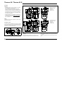
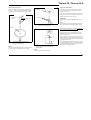
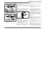
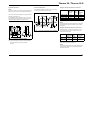
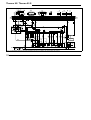
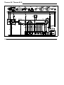
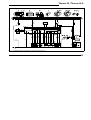
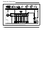
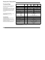
Thermo 90 / Thermo 90 S
Installation
Thermo 90
5
3
CAUTION:
- The legal provisions on page 1, relating to the installation of the heater, must be observed
- When installing the Thermo 90-TRS in vehicles designed for the transport of hazardous materials the requirements laid down in TRS 002 and TRS 003 (Technical Guidelines relating to the ordinance of transporting
hazardous goods on the road) must be fulfilled in addition to those of the StVZO.
Combustion air inlet
Exhaust gas outlet
Fuel inlet
Coolant inlet
Coolant outlet
1
2
3
4
5
Combustion air inlet
Exhaust gas outlet
Fuel inlet
Coolant inlet
Coolant outlet
4
- If the water heater is to be operated in a separately installed heating system, it is mandatory that the installation drawing be submitted to Webasto for approval
prior to installation.
NOTE:
The different vehicle-specific installation conditions should
be taken into account.
1
2
3
4
5
2
1
Thermo 90 S
5
3
Installation Location
The heater should be installed at a level as low as possible
so as to ensure automatic venting of the heater and the circulating pump. This is of special importance as the circulating pump is not of the self-priming type.
4
1
Fig. 2:
2
Dimensions of the Heater
Type Plate
Fig. 1:
2
Installation Position T90 / T90S
The type plate must be located in a place where it is protected against damage and be easily accessible once the
heater has been installed (or else, a type plate duplicate is
to be used).
The years not applicable are to be removed from the type
plate.