1
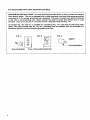
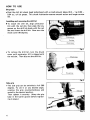
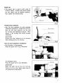
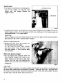
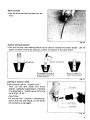
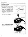
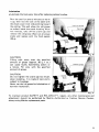
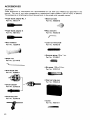
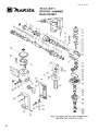
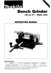
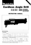
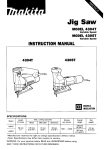
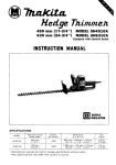
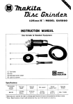
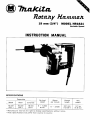
19 mm (3/4") MODEL HR1821
Variable Speed
INSTRUCTION MANUAL
Capacities
Wood
Steel
15"
(518")
10"
(3/8")
Concrete
19"
(314"
No load
speed
0 A
/; O
:i, O
Blows
per minute
0
-
3,500
Overall
length
Net
weight
321 mm
(12-518")
3.1 kg
(6.8 Ibs)
IMPORTANT
SAFETY INSTRUCTIONS
(For All Tools)
WARNING: WHEN USING ELECTRIC TOOLS, BASIC SAFETY PRECAUTIONS SHOULD ALWAYS BE FOLLOWED TO
REDUCE THE RISK OF FIRE, ELECTRIC SHOCK, AND PERSONAL INJURY, INCLUDING THE FOLLOWING:
READ ALL INSTRUCTIONS.
1. KEEP WORK AREA CLEAN. Cluttered areas and benches invite injuries.
2. CONSIDER WORK AREA ENVIRONMENT. Don’t use power tools in damp
3.
4.
5.
6.
7.
8.
9.
IO.
11.
12.
13.
or wet locations. Keep work area well lit. Don‘t expose power tools t o rain.
Don‘t use tool in presence of flammable liquids or gases.
KEEP CHILDREN AWAY. All visitors should be kept away from work area.
Don’t let visitors contact tool or extension cord.
STORE IDLE TOOLS. When not in use, tools should be stored in dry, and
high or locked-up place - out of reach of children.
DON’T FORCE TOOL. It will do the job better and safer at the rate for which
it was intended.
USE RIGHT TOOL. Don’t force small tool or attachment to do the job of
a heavy-duty tool. Don’t use tool for purpose not intended.
DRESS PROPERLY. Don’t wear loose clothing or jewelry. They can be caught
in moving parts. Rubber gloves and non-skid footwear are recommended
when working outdoors. Wear protective hair covering t o contain long hair.
USE SAFETY GLASSES. Also use face or dust mask if cutting operation
is dusty.
DON’T ABUSE CORD. Never carry tool by cord or yank it to disconnect from
receptacle. Keep cord from heat, oil, and sharp edges.
SECURE WORK. Use clamps or a vise t o hold work. It’s safer than using
your hand and it frees both hands t o operate tool.
DON’T OVERREACH. Keep proper footing and balance at all times.
MAINTAIN TOOLS WITH CARE. Keep tools sharp and clean for better and
safer performance. Follow instructions for lubricating and changing accessories. Inspect tool cords periodically and if damaged, have repaired by
authorized service facility. Inspect extension cords periodically and replace
if damaged. Keep handles dry, clean, and free from oil and grease.
DISCONNECT TOOLS. When not in use, before servicing, and when changing accessories, such as blades, bits, cutters.
14. REMOVE ADJUSTING KEYS AND WRENCHES. Form habit of checking t o
15.
16.
17.
18.
19.
20.
21.
see that keys and adjusting wrenches are removed from tool before turning it on.
AVOID UNINTENTIONAL STARTING. Don't carry plugged-in tool with finger
on switch. Be sure switch is OFF when plugging in.
OUTDOOR USE EXTENSION CORDS. When tool is used outdoors, use only
extension cords intended for use outdoors and so marked.
STAY ALERT. Watch what you are doing, use common sense. Don't operate tool when you are tired.
CHECK DAMAGED PARTS. Before further use of the tool, a guard or other
part that is damaged should be carefully checked t o determine that it will
operate properly and perform its intended function. Check for alignment
of moving parts, binding of moving parts, breakage of parts, mounting, and
any other conditions that may affect its operation. A guard or other part
that is damaged should be properly repaired or replaced by an authorized
service center unless otherwise indicated elsewhere in this instruction manual. Have defective switches replaced by authorized service center. Don't
use tool if switch does not turn it on and off.
GUARD AGAINST ELECTRIC SHOCK. Prevent body contact with grounded
surfaces. For example; pipes, radiators, ranges, refrigerator enclosures.
PROPER GROUNDING. This tool should be grounded while in use t o protect the operator from electric shock.
EXTENSION CORDS: Use only three-wire extension cords which have threeprong grounding-type plugs and three-pole receptacles which accept the
tool's plug. Replace or repair damaged or worn cord immediately.
VOLTAGE WARNING: Before connecting the tool t o a power source (receptacle,
outlet, etc.) be sure the voltage supplied is the same as that specified on the
nameplate of the tool. A power source with voltage greater than that specified
for the tool can result in SERIOUS INJURY t o the user - as well as damage t o
the tool. If in doubt, DO NOT PLUG IN THE TOOL. Using a power source with
voltage less than the nameplate rating is harmful t o the motor.
3
For all grounded tools with American type plug.
GROUNDING INSTRUCTIONS: This tool should begrounded while in use to protect the operator
from electric shock. The tool is equipped with a three-conductor cord and three-prong groundingtype plug t o f i t the proper grounding-type receptacle. The green (or green and yellow) conductor
in the cord is the grounding wire. Never connect the green (or green and yellow) wire to a live
terminal. Your unit is for use on 115 volts and has a plug that looks like,Fig. "A".
An adapter Fig. "B" and "C" is available for connecting Fig. "A" type plugs t o two-prong recap
tacles. The green-colored rigid ear, lug, etc., extending from the adapter must be connected to a
permanent ground, such as a properly grounded outlet box.
FIG. A
FIG. 0
FIG. C
Adapter
Grounding Blade
4
Cover of Grounded Outlet Box
ADDITIONAL SAFETY RULES
1. Wear a hard hat (safety helmet) and an ear protector if necessary.
2. Be sure the drill bit is secured in place before operation.
3. Under normal operation, the tool is designed t o produce vibration. The
screws can come loose easily, causing a breakdown or accident. Check
tightness of screws carefully before operation.
4. In cold weather or when the tool has not been used for a long time, let the
tool warm up for several minutes by operating it under no load. This will
loosen up the lubrication. Without proper warm-up hammering operation
is difficult.
5 . Always be sure you have a firm footing.
Be sure no one is below when using the tool in high locations.
6 . Hold the tool firmly with both hands. Always use the side grip.
7 . Keep hands away from rotating parts.
8 . Do not leave the tool running. Operate the tool only when hand-held.
9. Do not point the tool at any one in the area when operating. The drill bit
could fly out and injure someone seriously.
IO. When drilling into walls, floors or wherever ”live” electrical wires may be
encountered, DO NOT TOUCH ANY METAL PARTS OF THE TOOL!
Hold the tool only by the plastic handle or the side grip t o prevent electric
shock if you drill into a “live” wire.
11. Do not touch the drill bit or parts close t o the drill bit immediately after operation; they may be extremely hot and could burn your skin.
SAVE THESE INSTRUCTIONS.
5
HOW TO USE
Bit grease
Coat the drill bit shank head beforehand with a small amount (about 0.5 - 1 g; 0.02 0.04 02.) of bit grease. This chuck lubrication assures smooth action and longer service
life.
0
Installing and removing the drill bit
To install the drill bit, align protrusion
(A) with the red dot, then align the key
groove on the drill bit shank with the red
dot and insert the drill bit. Now turn the
chuck cover 90 degrees.
I
I
Fig. 1
* T o remove the drill bit, turn the chuck
cover until protrusion (A) i s aligned with
the red dot. Then slip out the drill bit.
II
Key-groove
I
Fig. 2
Side grip
0The side grip can be swivelled a full 360
degrees. To set it a t any desired angle,
unscrew the grip counterclockwise and
swivel to the desired position.
Then tighten it securely. (Keep the grip
base in the barrel groove before tightening in place.)
Fig. 3
6
Depth rod
.The depth rod i s used to drill holes of
uniform depth. Loosen the thumb screw
set the depth rod to desired position,
then tighten the thumb screw.
Fig. 4
Handling dust collector
Use the dust collector for safe, sanitary
overhead operations. Install the drill bit,
then fix the dust collector on the end
by turning and applying pressure. Then
secure it by turning the metal retainer
clockwise.
0
Dust collector
CAUTION:
Empty the dust collector of i t s contents
after drilling every 2 or 3 holes.
Fig. !
How to work switchover mechanism
For Rotation + Hammering:
Press the push rod indCDodirection.
0
For Rotation only:
Press the Dush rod in &+direction.
Lb-
Push rod
CAUTION:
Press the push rod as far as it will go.
Failure to do so can cause rapid wear of
the switchover mechanism.
Fig. 7
Switch action
Tool speed is increased by increasing pressure on the trigger. To start the tool,
simply pull the trigger. Release the
trigger to stop.
,
Speed control screw
Fig. t
.A speed control screw is provided so that tool speed (RPM) can be changed a t the fullypulled trigger position. Turn the speed control screw clockwise (+) for higher speed and
counterclockwise (-) for lower speed.
CAUTION:
Before plugging in the tool, always check to see that the trigger switch actuates properly
and returns to the "OFF" position when released.
Hammer drilling operation
.Position the drill bit a t the location for
the hole, then pull the trigger.
Do not force the tool. Light pressure
gives best results. Keep the tool in position and prevent it from slipping away
from the hole.
When holes become clogged
.Do not apply more pressure when the
hole becomes clogged with chips or particles. Instead, run the tool a t idle, then
remove from the hole. By repeating this
several times, the hole will be cleaned out
completely.
Fig. 9
CAUTION:
When drilling in concrete, it is quite possible that the drill bit could hit a reinforcing rod
or some other object that could cause a kickback. Although this tool is equipped with
the torque limiter, protect yourself by holding the tool firmly with both hands. (Be sure
the side grip is secured tightly before operation.)
8
Blow-out bulb
0 Use the blow-out bulb to clean out the
hole.
Fig. 10
Anchor setting procedure
0 The drill bit has a red marking which can be used to indicate the anchor length. Use the
depth rod when drilling for setting a number of anchors a t the same depth.
ed marking
chor setting tool
Put a plug in the tip of
an anchor and hammer
it into concrete.
Screw in a bolt for
fastening equipment.
Fig.
fi
Drilling in wood or metal
Set the push rod for “rotation only.”
Then use the drill chuck and chuck
adapter (optional equipment), installing
it as described in “Installing and removing
the drill bit (P.6).”
CAUTION:
DO not perform “rotation + hammering“
action with the drill chuck, or the chuck
will probably be damaged.
I
\
Drill chuck
d
Fig. 12
9
MAINTENANCE
CAUTION:
Always be sure that the tool is switched off and unplugged before attempting to perform
inspection and maintenance.
Replacing carbon brushes
0
77
Both carbon brushes should be replaced
after about 150 hours of use. When the
resin insulating tip inside the carbon
brush is exposed to contact the commutator, it will automatically shut off
the motor. I f carbon brushes wear out
too quickly, ask Makita Authorized or
Factory Service Centers to determine
the cause before replacing them. Use
only Makita carbon brushes.
Insulating tip
Fig. 1
*Use the screwdriver to remove the brush
holder cap as shown in the figure.
Fig. 14
Take out the worn brush, insert the new
one and secure the brush holder cap.
I
I
Fig. 15
10
Lubrication
Lubricate t h e tool every time after replacing carbon brushes.
0
Run the tool for several minutes to warm
it up, then rest the tool on the table with
the chuck cover (bit) end pointing toward
the ceiling. This will allow the old grease
to collect inside the crank housing. After
five minutes, take off the crank cap and
remove the old grease. Wipe out all grease
inside and replace with the fresh supply
(309).
Fig. 16
CAUTION:
Filling with more than the specified
amount of grease (approx. 30 g; 1 02.)
can cause faulty hammering action or
a failure. Fill only with the specified
amount of grease.
CAUTION:
Do not tighten the crank cap too much,
when installing. It i s made of resin and i s
subject to breakage.
Never use the bit grease for lubrication of
hammer mechanism.
To maintain product SAFETY and RELIABILITY, repairs, any other maintenance and
adjustment should be performed by Makita Authorized or Factory Service Centers,
always using Makita replacement parts.
11
ACC ESSOR IES
CAUTION:
These accessories or attachments are recommended for use with your Makita tool specified in this
manual. The use of any other accessories or attachments might present a risk of injury to persons.
The accessories or attachments should be used only in the proper and intended manner.
0
0
Taper shank adapter No. 1
0
Part No. 7650096
Taper shank adapter A
Hex wrench 5
Part No. 7832038
Part No. 798176-2
0
Dust collector
0
Lock nut wrench 28
Part No. 782402-9
0
Hammer grease 30 g; 1 02.
Part No. 181490-7
Part No. 122290-6
0
Blowout bulb
Part No. 798131-4
Depth rod
Part No. 321 144-6
*Bit grease 100 g; 3.5 oz.
Part No. 181573-3
0
Drill chuck S10
Part No. 763056-1
1
0
Chuck adapter
Part No. 321832-5
0
t
0 Steel
carrying case
Part No. 155826-6
Chuck key S10
Part No. 7634038
0
Cotter
Part No. 765010-1
12
0
Anchor setting rod (Manual setting)
Tungsten-carbide tip bits
765014 3
No 2 5
Part No
Blt
diameter
Max drilling
depth
765015 1
Makita anchor only
Overall
lenath
Anchor settinq rod
1
0
0
Anchor setting rod for interior applications
Anchors (30 sets per pkg)
(Set by tool)
I
Anchor
N~
No.2
NO 2
1 I 11 I
outer
d y z e r
1 1 17/16")
5 12 Ill2")
Overall
leegmf:
Thread
30 ( 1 3/16") W 114''
Plug
Thread
k3;g_f;
Part NO.
10 1318")
798054-6
35 11-318") W 5/16" 13 1112")
798056-2
NO 3
14.3 19/16") 40 I 1 518") W 318''
15 1518")
N0.4
17.5l11/16"~50
12")
2 0 (13/16") 798060-1
0
Anchor setting tool
Part No. 765012-7
W 112"
Anchor setting rod
for interior applications
798058-8
(Manual setting)
Plug
Anchor setting rod
for interior aoolications
13
Seo.--19-'84
@ma
-
US
19 mm (3/4")
ROTARY HAMMER
Model HR1821
Note: The switch and other part configurations
may differ from country to country.
14
MODEL HR1821
'ikM
,!D
Sep-19-'84
,!:,
DESCRIPTION
US
DESCRIPTION
MACHINE
~
7
8
9
10
11
12
13
14
15
16
17
18
19
20
21
22
23
24
25
26
27
28
29
30
31
32
33
34
35
36
37
38
39
3
1
1
1
1
1
1
1
1
1
1
1
1
4
4
1
1
1
1
1
1
1
2
1
1
1
1
1
1
1
1
1
1
1
1
1
1
1
1
40
41
42
43
44
45
1
1
1
1
1
1
1
2
3
4
5
6
Steel Ball 6 4
Key 4
Cylinder Liner 20
Ball Bearing 3007
Nut M 3 0 3 - 3 6
Barrel
0 Ring 4 0
Flat Washer 30
Spiral Bevel Gear 26
Striker
0 Ring 16
0 Ring 16
Piston
Spring Washer 6
Hex Socket Head Bolt M6x50
Pl" 5
Makita Label
Crank Cap
0 Ring 3 5
Rod
Needle Bearing 8 1 0
Crank Shaft
Steel Ball 5 6
Compression Spring 6
Change Pin 8
Crank Housing
0 Ring 32
Ball Bearing 6002
Helical Gear 29
Flat Washer 1 5
Torque Limiter
Flat Washer 6
0 Ring 6 5
ea, tiouslng
Ball Bearing 6200
0 Ring 3 0
0
1
1 Seal 13
Fan 67
ARMATURE ASSEMBLY
iAssembled Items 38 - 40 & Item 4 2 )
Insulatnm Washer
Rubber Pin 4
Ball Bearing 608LB
011 Sea1 21
Felt Ring 2 0
0 Ring 4 0
46
47
48
49
50
51
52
53
54
55
56
57
58
59
60
61
62
63
64
65
66
67
68
69
70
71
72
73
74
75
76
77
78
1
3
1
1
1
1
2
1
1
1
1
1
1
1
1
1
1
1
2
2
1
4
1
2
2
1
2
3
1
2
2
1
1
79
82
83
85
86
87
88
89
90
91
92
93
1
1
1
1
1
1
1
1
1
1
1
1
- -
Seal Holder
Steel Ball 6 4
Impact Bolt
0 Ring 10
0 Ring 10
Drill Holder
Key 4
0 Ring 10
0 Ring 10
0 Ring 19
Change Ring
Steel Ball 4 fl
Leaf sprrng
0 Ring 19
Flat Washer 20
Spiro Lock Washer 20
Chuck Cover
Fan Gwde
Hex Bolt M5x40 lWith Washer)
Rivet 0-5
Name Plate
Hex Nut M 6
Label
Brush Holder Cap
Carbon Brush
Motor Housing
Pan Head Screw M6x16 IWith Washer)
Pan Head Screw M5x22 IWith Washer)
Handle Set lWith Item 851
Pan Head Screw M6x25 lWith Washer)
Pan Head Screw M4x18 (With Washer1
Strain Relief
CORD ASSEMBLY
IWith Cord Plug E Item 791
Cord Guard
Dust Cover
Switch
Handle Set IWith Item 741
Grip 37
Cap Square Neck Bolt MBx35
Belt
Grip Base
Rubber Washer 4 5
Thumb Screw M5x15
FIELD ASSEMBLY
Pan Head Screw M4x8 IWith Washer)
Note The switch and other part specifications may differ from country to country
15
MAKITA LIMITED ONE YEAR WARRANTY
Warranty Policy
Every Makita tool is thoroughly inspected and tested before leaving the factory. It is warranted to
be free of defects from workmanship and materials for the period of ONE YEAR from the date of
original purchase. Should any trouble develop during this one-year period, return the COMPLETE
tool, freight prepaid, to one of Makita’s Factory or Authorized Service Centers. If inspection shows
the trouble is caused by defective workmanship or material, Makita will repair (or at our option,
replace) without charge.
This Warranty dses not apply where:
repairs have been made or attempted by others:
repairs are required because of normal wear and tear:
The tool has been abused, misused or improperly maintained;
alterations have been made to the tool.
IN NO EVENT SHALL MAKITA BE LIABLE FOR ANY INDIRECT, INCIDENTAL OR CONSEQUENTIAL DAMAGES FROM THE SALE OR USE OF THE PRODUCT. THIS DISCLAIMER
APPLIES BOTH DURING AND AFTER THE TERM OF THIS WARRANTY.
MAKITA DISCLAIMS LIABILITY FOR ANY IMPLIED WARRANTIES, INCLUDING IMPLIED
WARRANTIES OF “MERCHANTABILITY” AND “FITNESS FOR A SPECIFIC PURPOSE,”
AFTER THE ONE-YEAR TERM OF THIS WARRANTY.
This Warranty gives you specific legal rights, and you may also have other rights which vary from
state to state. Some states do not allow the exclusion or limitation of incidental or consequential
damages, so the above limitation or exclusion may not apply to you. Some states do not allow
limitation on how long an implied warranty lasts, so the above limitation may not apply to you.
~
~
.
L
t
d
11-8,J-chome. Sumiyorhi-cho, Anjo, Aichi 446, Japan
8834808065
PRINTED IN JAPAN
1986-2-N
.