1
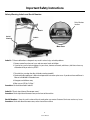
®
®
Bowflex® Series 3, 5 & 7 Treadmill
Service Manual
Nautilus® 001-7100-082510C
Bowflex® Schwinn® Fitness Universal®
Important -- Please Read
If you are a consumer and require technical support to resolve a problem with your Bowflex® 3, 5 or 7 Series
Treadmill, please call Nautilus Customer Service at 800-605-3369 (USA) or +01-360-859-5180 (International).
Voltages inside the Bowflex ® 3, 5 or 7 Series Treadmill are dangerous. Servicing by people other than
Authorized Nautilus® Service personnel may result in electrical shock or other injury.
Table of Contents
Important Safety Warnings - - - - - - - - - - - - - - - - - - - - - - - - - - - - - - - - - - - - - - - - - - - - - - - 1
Grounding Instructions - - - - - - - - - - - - - - - - - - - - - - - - - - - - - - - - - - - - - - - - - - - - - - - 2
Safety Warning Labels and Serial Number - - - - - - - - - - - - - - - - - - - - - - - - - - - - - - - - - 3
Emergency Stop Procedures - - - - - - - - - - - - - - - - - - - - - - - - - - - - - - - - - - - - - - - - - - - 4
Folding, Transporting & Unfolding your Treadmill - - - - - - - - - - - - - - - - - - - - - - - - - - - - - 5
Treadmill Specifications - - - - - - - - - - - - - - - - - - - - - - - - - - - - - - - - - - - - - - - - - - - - - - - - 6
Electrical Layout - - - - - - - - - - - - - - - - - - - - - - - - - - - - - - - - - - - - - - - - - - - - - - - - - - - - - - 8
Common Service Procedures - - - - - - - - - - - - - - - - - - - - - - - - - - - - - - - - - - - - - - - - - - - - - 9
Calibration---- - - - - - - - - - - - - - - - - - - - - - - - - - - - - - - - - - - - - - - - - - - - - - - - - - - - - - 9
Walking Belt Tension - - - - - - - - - - - - - - - - - - - - - - - - - - - - - - - - - - - - - - - - - - - - - - - 10
Walking Belt Centering - - - - - - - - - - - - - - - - - - - - - - - - - - - - - - - - - - - - - - - - - - - - - - 10
Troubleshooting Procedures - - - - - - - - - - - - - - - - - - - - - - - - - - - - - - - - - - - - - - - - - - - - - 11
General Power Source and Electrical Plug Set Up - - - - - - - - - - - - - - - - - - - - - - - - - - - 11
No Power to the Unit - - - - - - - - - - - - - - - - - - - - - - - - - - - - - - - - - - - - - - - - - - - - - - - 11
Console Error Codes - - - - - - - - - - - - - - - - - - - - - - - - - - - - - - - - - - - - - - - - - - - - - - - - 12
Elevation Problems - - - - - - - - - - - - - - - - - - - - - - - - - - - - - - - - - - - - - - - - - - - - - - - - - 14
Replacing Parts - - - - - - - - - - - - - - - - - - - - - - - - - - - - - - - - - - - - - - - - - - - - - - - - - - - - - 15
Walking Belt Replacement - - - - - - - - - - - - - - - - - - - - - - - - - - - - - - - - - - - - - - - - - - - 15
Important Safety Instructions
This icon means a potentially hazardous situation which, if not avoided, could result in death or serious injury.
Obey the following warnings:
R
ead and understand the Service Manual before working on the machine. Failure to obey the instructions and
safety warnings could cause injury to the service technician or bystanders.
•
Keep children away from the product being serviced at all times..
•Make sure that the repair is done in an appropriate work space away from foot traffic and exposure to bystanders.
•
Disconnect all power and allow to sit for 5 min. before you service this machine.
•
Some components of the equipment can be heavy or awkward. Enlist the service of a second person when you do
maintenance steps involving these components. Do not try to do heavy or awkward steps on your own.
•
Use only genuine Nautilus supplied or approved replacement parts and hardware. Failure to use genuine
replacement parts can adversely effect the safety and functionality of the equipment creating a risk to users.
•
Be sure that all warning stickers and instructional placards applied to the product stay present and in good condition
when doing maintenance or replacing components. If necessary request replacement warning stickers or placards
from Nautilus customer service.
•
Do not try to change the design or functionality of the machine being serviced as this can adversely effect user
safety.
•
Do not use the machine until all shrouds, instructions, warning labels and correct functionality have been verified
and tested for correct performance.
Grounding Instructions
This product must be grounded. If it should malfunction or break down, grounding provides a path of least resistance for
electric current, reducing the risk of electric shock. The power cord is equipped with an equipment-grounding conductor
and a grounding plug. Keep this plug in an appropriate outlet that is properly installed and grounded in accordance with
all local codes and ordinances.
Nautilus, Inc., (800) NAUTILUS / (800) 628-8458, www.NautilusInc.com - Customer Service: North America (800) 605-3369 | Outside the US +01-360-859-5180 | ©2010. Nautilus, Inc. All rights
reserved. Nautilus, Inc. (www.NautilusInc.com) trademarks include NAUTILUS®, BOWFLEX®, SCHWINN® and UNIVERSAL® and respective logos. Other trademarks are the property of their
respective owners.
1
Service Manual
Important Safety Instructions
Safety Warning Labels and Serial Number
Serial Number
location
Label 1
Serial
Number
Label 2
Motor Cover
Label 1: "Failure to follow these safeguards may result in serious injury or health problems.
1. Remove control key when not in use and store out of reach of children.
2. If you feel any unusual pain or tightness in your chest, shortness of breath, or dizziness, feel faint or have any
discomfort while you exercise, STOP!
1. To avoid injury, stand on the side rails before starting treadmill.
2. Read and understand Owner's Manual and operation instructions prior to use. If you do not have and Owner's
Manual call 800-864-1270 to obtain one.
3. Keep pets and children away.
4. Max user wt. 275 lbs / 125 kgs. "
Location: On the inside of both handrails. Label 2: "Electric shock hazard. Do not open cover."
Location: On the right side of the motor cover, on the front of the machine.
Serial Number: Have the serial number of the unit ready when you contact Customer Service to resolve any issues.
Location: On the left side of the motor cover, on the front of the machine.
2
Service Manual
Important Safety Instructions
Emergency Stop Procedures
Your treadmill comes equipped with a SAFETY KEY that can protect you from serious injury. The safety key
uses a magnetic key to hold it in the proper position. Insert the safety key fully into the safety keyhole.
Always clip the Safety Key Clip to your clothing during your workout. Unless there is
an emergency, do not remove the safety key when standing on the walking belt while in
motion.
Magnetic Stop Key
The treadmill stops immediately if the safety key is removed from the treadmill while in use. This feature
prevents serious harm and, when used properly, can be an excellent way to protect your safety during a
workout.
NOTICE: For an immediate stop, press the POWER button, the STOP button, or remove the safety pull
pin. CAUTION – THE BELT STOPS ABRUPTLY.
3
Service Manual
Important Safety Instructions
Folding, Transporting & Unfolding the Treadmill
This treadmill comes with a folding mechanism. You must
stop operation before folding and transporting the machine.
Make sure the power is off and the power cord is removed
and unplugged before folding and transporting the treadmill.
Folding the treadmill:
1. Stop the treadmill belt.
2. Bring Elevation to zero.
3. Turn off power.
4. Squeeze the release mechanism, then lift the deck
to fold up the treadmill. Make sure the pin clicks into
position and the deck is secure before moving the
treadmill.
Transporting the treadmill:
1. Make sure deck is locked/engaged in the up position
after folding.
2. Remove Power cord.
3. Hold the top of the deck and pull backwards until the
wheels move smoothly.
Unfolding the treadmill:
Squeeze the release mechanism down and gently lower the
deck until it sits on level ground.
Do not use the uprights, arms, or console to lift or move the Bowflex ® Treadmill. Doing so causes physical
injury to you, and can cause damage or destroy the Bowflex ® Treadmill.
4
Service Manual
Specifications
The dimensions and general specifications for the Bowflex® 3, 5, or 7 Series Treadmill include:
Product Weight
Series 3
Series 5
Series 7
298 lbs. / 135 kg
298 lbs. / 135 kg
298 lbs. / 135 kg
Maximum User
Weight
Series 3
Series 5
Series 7
275 lbs. / 125 kg.
275 lbs. / 125 kg.
300 lbs. / 136 kg.
Motor Size
Series 3
Series 5
Series 7
1.75 Horsepower
2.5 Horsepower
3.0 Horsepower
Speed
Series 3
Series 5
Series 7
.5 - 10 mph
.5 - 10 mph
.5 - 11 mph
Incline Range
Series 3
Series 5
Series 7
Range - 0-12%
Range - 0-12%
Range - 0-12%
Walking Surface
Series 3
Series 5
Series 7
20” x 54” / 51 x 137 cm
20” x 60” / 51 x 152 cm
20” x 60” / 51 x 152 cm
Belt
Series 3
Series 5
Series 7
1 - ply
1 - ply
2 - ply
Warranty
See Warranty card for detailed warranty information
5
Service Manual
Electrical Layout
1.
2.
3.
4.
5.
6.
7.
8.
Top Black cable (speed sensor)
Middle Red wire (up elevation)
Middle Black wire (down elevation)
Middle White wire (elevation Com)
Blue wire (N/L2)
Brown Wire (AC/L1)
Bottom Left Black wire (A2 Motor)
Bottom Right Red wire (A1 Motor)
Lights next to Middle Red wire
1. Left (elevation up)
2. Right (elevation down)
Fuses
1. Middle Left ( 0.5 amp main board)
2. Middle Right ( 1. 5 amp AC – incline)
3. Gray Fuse under Blue and Brown wire
(15 amp DC power)
Lights
1. Top Left (PWM)
2. Top Middle (speed sensor)
3. Top Right (V_Console)
Plug and Switch configuration
Plug and switch wiring
configuration
1. Connects with N/(L2) On control board
2. Connects with AC/(L1) On control board
6
Service Manual
Common Service Procedures
Calibration
Calibrate the Treadmill after replacing a component, like
a belt or motor, and after a power outage. Calibrating
the Treadmill is an important part of troubleshooting and
maintenance.
Do not stand on the walking belt during the entire
calibration process. Stand on the side foot support
platforms or rubber mat only.
1. Plug power cord into wall outlet and turn on power
switch.
2. Stand on the side foot support platforms or rubber
floor mat. DO NOT STAND ON THE WALKING
BELTS.
3. Insert the Safety Key.
Note: The Bowflex® Treadmill does not power up
if the Safety Key is not fully inserted into the safety
keyhole.
4. Press and hold hold “ENTER” and “POWER” for 3
seconds while the Console is dormant. The word
“CAL” shows on the display.
5. Press “START”. This enables display of maximum
speed (with unit of measure) and maximum incline.
6. Verify correct units of measure (English imperial/
metric). Press “START” to change from one type
to another. Press “ENTER” one time to set the
measurement unit.
7. Press “START”.
8. Press “POWER” again to save and exit, once
calibration is complete.
7
Service Manual
Common Service Procedures
Walking Belt Tension The walking belt tends to stretch slightly with use, thus it may
need to be tightened. If the walking belt is too loose, the belt
may stop during operation (running or walking).
DO NOT OVERTIGHTEN BELT. Too much tension on the belt
causes unnecessary friction and wears the belt, motor,
rollers and electronics. To make sure the belt tension is
correct, put three fingers under the edge of the stationary
walking belt. You should be able to lift the side of the belt
approximately 2-3 inches (5-7 centimeters).
Adjustment screws
To Tighten Belt
1. Use the hex key provided with the treadmill. Place
the hex key in the hole in left end cap and into the
socket of the adjustment screw.
2. Turn key one full turn clockwise.
3. Place hex key in hole in right end cap and turn key
one full turn clockwise.
4. Check the tension of the belt.
5. Continue adjusting each side if the belt, back and
forth, until belt tension is correct.
6. Make sure to adjust both sides equally to keep the
belt correctly aligned.
Close up of an adjustment screw hole
Walking Belt Centering
The walking belt may need to occasionally be centered.
First, check the belt tension. It must be correctly adjusted.
Run the treadmill at about 3.5 mph (6km/h). Place the hex key
through the hole in the left end cap and into the socket of the
adjustment screw.
If Belt Moves to the Right
1. Turn the right adjustment screw 1/2 turn clockwise,
then turn the left adjustment screw 1/2 turn
counterclockwise.
2. If belt does not move, repeat until belt is centered.
3. Recheck the tension of the belt (see above).
If Belt Moves to the Left
1. Turn the right adjustment screw 1/2 turn
counterclockwise, then turn the left adjustment
screw 1/2 turn clockwise.
2. If belt does not move, repeat until belt is centered.
3. Recheck the tension of the belt (see above).
8
Service Manual
Troubleshooting Procedures
General Power Source and Electrical Plug Set Up
Plug the treadmill into its dedicated outlet. If possible, use
a surge protector. Treadmill does not operate correctly on a
GFI basement or garage outlet.
No Power to the Unit
1. Check power to the outlet.
2. Check plug at unit and AC inlet receptacle for
damage
3. Check circuit breaker (red pin by on/off switch). If it
is tripped, it will be popped out and you will need to
click it back in. If it is not tripped, it will not move.
4. Remove the motor cover to see if any LED light are
lit on the lower control board.
5.
5. Use a multi-meter to verify if voltage is getting past
the circuit breaker, if you do not see any LED lights
lit on the power supply. Replace the circuit breaker
if no voltage shows.
6. If the LED lights are on (indicating current past
the circuit breaker) then check if the safety key is
functioning by removing and replacing it. When this
is done you should get a beep and the software
version shows on the Display.
7. If the LED lights are on and the safety key is not
functioning (and no power to upper board), use a
multi-meter to test if DC voltage goes to the upper
electronics. On a unit with the telco style cables,
you should check the 8 PIN cable on the #2 and #5
pins, getting a reading between 2 and 12 DC volts.
If it is the I/O cables with the white ends, it would
be the #4 PIN (yellow wire) and #6 PIN (blue wire).
If you are not getting any reading, then check the
connections and replace if necessary.
8. Replace the limit switch if there is no reading and
the safety key does not respond.
9. Replace the upper electronics if you have checked
all the above and they are functioning properly and
you still have no power.
9
Service Manual
Troubleshooting Procedures
Console Error Codes
ENGINEERING MODE
1. “rdir”: This error code means elevation direction is
reversed. Refer to elevation problems section.
2. “Rg_S”: This error means the target speed cannot
be maintained. Refer to Speed Errors section.
3. “St_E”: This error code means an elevation stall
happpened (elevation is commanded to move but
nothing happens). Refer to Elevation Problems
section.
4. “LS_E”: This error means that an elevation range
error (elevation position is out of range). Refer to
Elevation Problems section.
5. “LS”: This error message means a speed stall (belt
is commanded to move but no feedback from the
speed sensor). Refer to Speed Errors section.
6. “OS”: This error message means an over speed or
runaway error (speed is over the maximum). Refer
to Speed Errors section.
7. “Lub bELt”: The lubricate belt message shows
every 250 miles of belt travel. The message “Lub
bELt” shows on the left and right displays upon
waking up from sleep mode. This message remains
there until any key is pressed. Once any key is
pressed, the weight menu is activated.
To enter Engineering Mode: Press and hold down the
enter and power keys until “CAL” shows in the upper right
window. The Display must be in the “sleep” screen mode in
order for this to work.
ROLLER DIAMETER
1. Enter engineering mode.
2. Press start once. Max speed and units shows
(“E”= ENGLISH, “n”= METRIC).
3. Press the enter key once. After a slight delay, a
beep sounds and “CAL” shows in the upper right
window.
4. Use the up/down keys to scroll until “roLL” shows
in the upper right window.
The belt will start moving.
5. Press the start key. The roller diameter shows in
the upper left display, actual speed in the upper
right display and current PWM show in the lower
right display.
6. Adjust the roller diameter until the speed in the
Display matches the actual speed of the belt.
Speed Errors
7. Press enter to save, or power to exit without
saving.
Note: Speed sensor adjustment and/or calibration usually
fixes any speed errors.
a. Check distance of speed sensor to magnet on roller AUTO CALIBRATION
pulley wheel. It should be 1/8”.
1. Enter engineering mode.
b. With the power to the unit on, check to see if speed
2. Press start once. Max speed and units shows
sensor light is flashing each time magnet passes
(“E”= ENGLISH, “n”= METRIC).
speed sensor by moving walking belt with your hand
or foot.
3. Press the enter key once. After a slight delay a
beep sounds and “CAL” appears in the upper right
c. Check speed sensor wire from speed sensor to
window.
lower board for breakes or cuts. Replace speed
sensor if light still does not respond.
4. Press the start key. The system enters the auto
calibration mode. When auto calibration is
d. Calibrate unit if speed sensor works. If calibration
complete, the system shows the results.
fails, check the maximum PWM output during the
calibration. If it does not achieve between 170 and
5. Press power to exit the Auto Calibration mode.
200, replace the lower control board. Also check
the voltage output on the A1 and A2 terminals. You
MANUAL CALIBRATION
should briefly get a reading of 15 or more DC volts
1. Enter engineering mode.
when pressing START as if engaging the unit for belt
movement.
2. Press start once. Max speed and units shows
(“E”= ENGLISH, “n”= METRIC).
10
Service Manual
Troubleshooting Procedures
3. Press the enter key once. After a slight delay, a
beep sounds and “CAL” appears in the upper right
window.
4. Press the start key. The system enters the auto
calibration mode.
5. Press the start/stop key to pause auto calibration.
6. Press the enter key to manually toggle through
the calibration points while and save your current
values. Press the scan keys to toggle through
without saving. The order is: MIN PWM, ½ PWM,
MAX PWM, ELEVATION UPPER LIMIT, ELEVATION
LOWER LIMIT.
On the belt calibration screens, the actual speed shows
in the upper left window, the current PWM shows
in the upper right window and the target calibration
speed shows in the lower right window.
On the elevation calibration screens, the input volts
shows in the upper left, the a/d ticks shows in the
upper right and the mode shows in the lower right.
HARDWARE TEST
1. Enter engineering mode.
2. Press start once. Max speed and units shows (“E”=
ENGLISH, “n”= METRIC).
3. Press the enter key once. After a slight delay, a
beep sounds and “CAL” appears in the upper right
window.
4. Use the up/down keys to scroll until “tESt” shows in
the upper right window.
5. Press the start key.
The elevation keys directly control the elevation, the
speed keys directly control the belt PWM, and the scan
keys manually ramp up and down the fan PWM. The
fan keys are also enabled.
DISPLAYS
•
•
•
•
Upper Left = Actual HR
Upper Right = Actual Speed
Lower Left = Elevation A/D counts
Lower Right = Belt PWM
11
Service Manual
Troubleshooting Procedures
Elevation Problems
If you have elevation problems, follow these steps to diagnose and repair the problem(s):
1. Calibrate the unit. Calibration will correct the
problem or diagnose the cause. While the unit is
in calibration, the potentiometer reading should
decrease when going up and increase while going
down. The elevation numbers increase as the
platform rises and decreases as it goes down.
2. If the problem continues, do the following:
a. With the power ON, press the START and
INCLINE UP buttons. The INCLINE UP light
should come on, indicating the command was
received at the lower board. If the light does not
come on: check the connections of the 8 PIN
cables to the upper and lower boards. Replace
the cables if the light on the lower board still
does not respond to the command.
Note: The down light does not respond unless
the machine has elevation.
b. If the UP ELEVATION light comes on, and the
machine does not elevate: disconnect the white
wire (elevation common), black wire (flat unit),
and red wire (folding unit) from the lower board.
Press POWER and START, then push the UP
ELEVATION button. Check the voltage from each
terminal, with a multi-meter. The tool should read
220 to 230 A/C volts.
c. If you do not get a reading of 220 to 230 A/C volts,
but the light responds: change the lower control
board.
d. If you get a voltage reading from these ports
without pressing the UP ELEVATION button,
or the UP light is stuck on: the machine has
a bad overlay or a stuck button on the upper
electronics board. Replace the overlay and the
button.
d. If you get a reading of 220 to 230 A/C volts
when pressing the UP ELEVATION button and
the machine does not elevate: check for an
OHMS reading on the red and black wire of
the potentimeter. Replace the potentiometer if
you do not get an OHM reading. Replace the
elevation motor if you do get readings.
3. Swap the up and down wires to return the machine
to a zero elevation if the unit gets stuck at an
incline. Calibrate the unit. If it does not correct the
elevation problem, follow above steps to diagnose.
12
Service Manual
Replacing Parts
Walking Belt Replacement
Troubleshooting Symptom: Cracked rubber on walking belt.
User feels static electricity or small shocks while running or
walking.
Disconnect all power and allow to sit for 5 min. before you
service this machine
Note: Set the hardware safely aside as you disassemble
components. Identify the correct size hardware for
each step to assemble the machine again.
1. Remove the motor cover (Figure 1).
Figure 1
2. Remove the plastic side step cover (Figure 2).
Figure 2
13
Service Manual
Replacing Parts
Walking Belt Replacement (cont.)
Motor Tension Bolt
3. Loosen the motor mounts. Release motor belt tension
by loosening the motor tension bolt. (See Figure 3.)
Motor Mounts
Figure 3
4. Remove motor drive belt from the motor pulley
(Figure 4). Slowly turn the motor pulley to help
“walk” the belt off the pulley.
Motor
Pulley
Figure 4
14
Service Manual
Replacing Parts
Walking Belt Replacement (cont.)
5. Remove the rear roller adjustment screws (Figure
5). You must loosen the screws equally to prevent
binding.
6. Remove rear roller.
Figure 5
7. Remove front roller bolts from the front roller axle
(Figure 6).
8. Remove front roller.
9. Lift deck into storage position. Refer to the
“Folding the Treadmill” section in this manual.
Figure 6
15
Service Manual
Replacing Parts
Walking Belt Replacement (cont.)
10. Remove rear wheels from their brackets.
11. Carefully peel back the side decal and remove
hardware as shown (Figure 7). Remove the plastic
bottom cover.
Figure 7
12. Remove 4 nuts from below the deck (Figure 8).
13. Unfold the deck. Refer to the “Unfolding the
Treadmill” section in this manual.
14. Remove the 8 hex screws on the top surface of the
deck.
Figure 8
16
Service Manual
Replacing Parts
Walking Belt Replacement (cont.)
15. Carefully remove the 4 plastic spacers between
the deck and frame mounts (Figure 9). Set aside for
reinstallation.
Figure 9
16. Lift and tilt the deck with belt from the frame, and
remove the old belt. (See Figure 10.)
17. Clean deck with damp rag. Clean and remove any
debris from below the deck.
Figure 10
17
Service Manual
Replacing Parts
Walking Belt Replacement (cont.)
18. Reverse the operation to install the replacement
belt and assemble the treadmill.
Note: When you install the roller bolts into the front
and rear roller axles (see Steps 7 and 5), it may
be easier if you use a tool to align the bolt holes
on one side (Figure 11) while you install the
other side.
Figure 11 – Align bolt holes (rear axle shown)
Note: When you put the rear roller back on the frame
(reverse of Steps 6 and 5), it may be necessary
to use a lever against the frame to install the
roller (Figure 12) due to the tightness of the new
walking belt.
Note: When you tighten the motor tension bolt (see
Step 3), adjust the tension until you can push
down the top surface of the motor drive belt
approximately 0.25” (0.64 cm).
19. Spray silicon lubricant between the new walking
belt and the deck.
Figure 12
18
Service Manual
Replacing Parts
Replacing the Upper Console
Please refer to the Assembly Manual.
19
Service Manual
Nautilus® Bowflex® Schwinn® Fitness Universal®