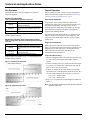
1
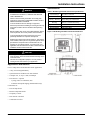
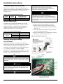
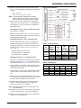
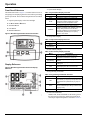
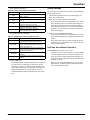
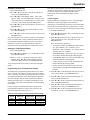
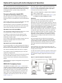
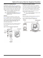
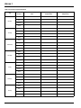
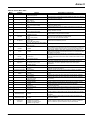
Installation and Maintenance Manual
IM 1019
Group: Fan Coil
Part Number: IM 1019
Date: October 2011
MT 180 Programmable Thermostat
© 2011 Daikin
Installation Instructions . . . . . . . . . . . . . . . . . . . . . . . 3
Applications and features . . . . . . . . . . . . . . . . . . . . . 3
Specifications . . . . . . . . . . . . . . . . . . . . . . . . . . . . . . 3
Thermostat Model and Part Number . . . . . . . . . . . . . 4
Optional Sensors/Kits . . . . . . . . . . . . . . . . . . . . . . . . 4
Installing, Mounting and Wiring the Thermostat . . . . 4
Operation . . . . . . . . . . . . . . . . . . . . . . . . . . . . . . . . . . . 6
Front Panel Reference . . . . . . . . . . . . . . . . . . . . . . . 6
Display Reference . . . . . . . . . . . . . . . . . . . . . . . . . . . 6
Saving Changes . . . . . . . . . . . . . . . . . . . . . . . . . . . . 7
Up/Down Arrow Button Operation . . . . . . . . . . . . . . . 7
System Button Operation . . . . . . . . . . . . . . . . . . . . . 8
Fan Button Operation . . . . . . . . . . . . . . . . . . . . . . . . 8
Program Button Operation . . . . . . . . . . . . . . . . . . . . 8
Function Overview . . . . . . . . . . . . . . . . . . . . . . . . 8
Setting the Clock & Day . . . . . . . . . . . . . . . . . . . . 9
Setting the Temperature Display . . . . . . . . . . . . . 9
Programming Time & Temperature Settings . . . . 9
Overriding the Program . . . . . . . . . . . . . . . . . . . . 10
System Check-out . . . . . . . . . . . . . . . . . . . . . . . . . . 11
Condensate Overflow Interrupt . . . . . . . . . . . . . . . . 11
Thermostat configuration/ Service Menu . . . . . . . . 11
Technical and Application Notes . . . . . . . . . . . . . .
Fan Operation . . . . . . . . . . . . . . . . . . . . . . . . . . . .
Standard Fan Operation . . . . . . . . . . . . . . . . . .
Staged Fan Operation with
Temperature Demand . . . . . . . . . . . . . . . . . . . .
Fancoil Operation . . . . . . . . . . . . . . . . . . . . . . . . . .
Pipe Sensor Operation . . . . . . . . . . . . . . . . . . .
Purge Cycle Operation . . . . . . . . . . . . . . . . . . .
HVACSetback Systems . . . . . . . . . . . . . . . . . . . . .
Setback Operation - Remove JP3 . . . . . . . . . . .
Door Switch Only Operation - Install JP3 . . . . .
12
12
12
12
12
12
12
13
13
13
Optional Occupancy Detection
Equipment Operation . . . . . . . . . . . . . . . . . . . . . . . .
Occupancy Operation (Install JP3) . . . . . . . . . . . .
Operation From an Occupied Mode . . . . . . . . .
Operation From an Unoccupied Mode . . . . . . . .
SB200-001 Occupancy Sensor . . . . . . . . . . . . . . .
Operation . . . . . . . . . . . . . . . . . . . . . . . . . . . . . .
SD200-001 Occupancy Sensor . . . . . . . . . . . . . . .
Operation . . . . . . . . . . . . . . . . . . . . . . . . . . . . . .
SD200-002 Occupancy Sensor . . . . . . . . . . . . . . .
Operation . . . . . . . . . . . . . . . . . . . . . . . . . . . . . .
14
14
14
14
14
14
15
15
15
15
Annex I . . . . . . . . . . . . . . . . . . . . . . . . . . . . . . . . . . . 16
Annex II . . . . . . . . . . . . . . . . . . . . . . . . . . . . . . . . . . . 17
2
Daikin IM 1019
Installation Instructions
Installation Instructions
Specifications
WARNING
• READ THESE INSTRUCTIONS CAREFULLY BEFORE
ATTEMPTING TO INSTALL, OPERATE OR SERVICE
THIS THERMOSTAT.
• Failure to observe safety information and comply with
instructions could result in PERSONAL INJURY, DEATH
AND/OR PROPERTY DAMAGE.
• To avoid electrical shock or damage to equipment,
disconnect power before installing or servicing and use only
wiring with insulation rated for full thermostat operating
voltage.
• Before installing this control, the Voltage Selection Switch
must be placed in the correct position. See instructions.
Table 1: MT180 Programmable Thermostat Specifications
Temperature
Set Point Range
Differential
Memory – Back-Up
Mounting
Physical Dimensions
Agency Approvals
Electrical Ratings
50 to 90°F / 10 to 32°C
1°
EEPROM, No batteries required,
Stores settings for unlimited time
Installs on standard 4" x 4" device box
with a 2" x 4" horizontal mud ring
4.4"H x 5.8"W x 1.1"D
UL, UL Canada
(see Ratings table)
Figure 1: MT180 Programmable Thermostat Dimensions
• To avoid potential fire and/or explosion do not use in
potentially flammable or explosive atmospheres.
• Retain these instructions for future reference. This product,
when installed, will be part of an engineered system whose
specifications and performance characteristics are not
designed or controlled by PECO. You must review your
application and national and local codes to assure that your
installation will be functional and safe.
CAUTION
• Use copper wire only, insulate or wire nut all unused leads.
• Care should be used to avoid electrostatic discharge to the
T180 thermostat.
• This unit has configuration jumpers. You may need to
reconfigure this thermostat for your application
Applications and features
For 2 or 4 Pipe Fan Coil and On/Off Control Applications
• 7 Day, 4 Event Programmability
• System Selection: Off-Heat-Cool-Auto-Setback
• 6 Outputs: 1H, 1C, Up to 3 Fan, OA Damper
• Fan Control: 1-3 Speeds
- Cycling (Auto) or Continuous (On)
- Automatic Fan Speed Staging (TB180 models only)
Connections for:
• Fan Coil Pipe Sensor
• Remote Temperature Probe
• Occupancy Control
• Door Switch or Setback
• Condensate Overflow
Daikin IM 1019
3
Installation Instructions
Thermostat Model and Part Number
Daikin offers two different 7-Day Programmable Digital
Heating/Cooling Thermostat with constant fan or Fan cycled,
On/Off Valve Control depending on the fan speed control
used (See Table 2).
.
Table 2: Thermostat Model and Part Number
Model
Number
Part
Number
Fan Speed Control
TA180-001
TB180-001
910119110
910119111
3-speed fan control
Staged fan control
• Use copper wire only. Insulate or wire nut all unused leads.
• Avoid electrostatic discharge to the thermostat.
• Failure to do so can cause thermostat malfunction or
permanently damage the thermostat.
DANGER
Hazardous voltage. Combined load current is not to exceed 20
amps. Mount only to a grounded metallic box.
Low voltage wiring is Class 2. To avoid electrical shock or
Damage to equipment, disconnect power before installing or
servicing. Failure to follow these instructions will result in death
or serious injury
Optional Sensors/Kits
In addition to the T180 thermostat, Daikin offers optional
sensors for occupancy detection (page 14 and page 15) and
10K pipe sensor page 12) that can be ordered and used in
conjunction with the thermostat. Use the associated kit
number(s) provided in Table 3 when ordering.
1 Disconnect power before installing or servicing.
2 Run line voltage wiring (and low voltage wiring if
applicable) into the field provided outlet box and mud
ring (Figure 2).
3 Locate all connections within the mud ring/connection
box and wire nut all unused wires.
Table 3: Sensor Model and Kit Numbers
Sensor Model Number
Daikin Part Number
SB200-001
SD200-001
SD200-002
10K Pipe Sensor
Occupancy
Detection
Sensor
6677877311
6677877411
6677877511
107201601
4 Remove the thermostat cover assembly from its base to
gain access to the circuit board (Figure 3).
Figure 2: Mounting the Thermostat
Installing, Mounting and Wiring
the Thermostat
The thermostat should be used indoors only. It should be
mounted on an inner wall in a location with freely circulating
air, and where it will be responsive to changes in room
temperature. Avoid mounting near heat generating appliances
(i.e. TV, heater, refrigerator), or in direct sunlight.
The thermostat base mounts to a field provided 4" × 4" outlet
box with a 2" × 4" horizontal mud ring. The thermostat cover
assembly mounts to the thermostat base.
.
CAUTION
Before applying power, the voltage selection switch must be in
the appropriate position. Failure to select the correct voltage
can cause thermostat malfunction or permanently damage the
thermostat.
Figure 3: Circuit Board
CAUTION
To use a remote sensor on units with local sensing capability,
remove jumper JP1 to disable local sensing. Failure to remove
JP1 can cause improper operation of the thermostat with a
remote probe installed.
CAUTION
4
Daikin IM 1019
Installation Instructions
5 On the circuit board, set the voltage selection switch
Figure 4: Wiring Diagram
(Figure 3) to the appropriate position prior to application
of power.
•
24V = 24 VAC
•
110-277 V = 120, 240 or 277 VAC
Note: The circuit board is shipped with the voltage
selection switch in the 110-227 V position. For 24
VAC use, the switch must be in the 24 V position
6 The circuit board is also equipped with configuration
jumpers (JP1, JP3, and JP4 in Figure 3). Depending on
the application, it may be necessary to reconfigure the
following jumpers:
JP1 Jumper Selection – Remote Temperature Sensor
Local Sensing – Install JP1
Remote Sensing – Remove JP1 – Accessory sensors are
available in standard 60" lengths but can be extended to
meet application requirements.
JP3 Jumper Selection – HVAC Setback Systems
The JP3 jumper allows the T180 to be configured for
Setback, Occupancy Detection or Door Switch Only
Occupancy Operations. For further descriptions of these
conditions please see the Technical and Application
Notes‚ page 12.
Table 4: Jumper Activation
JP4
Section
• Setback Operation - Remove JP3
• Occupancy Detection - Install JP3
• Door Switch Only - Install JP3
JP4 Jumper Selection – 2 or 4 Pipe Operation
Connection of a pipe sensor will change the operation of
the outputs as shown in Table 4. (See Technical Notes for
further information on Pipe Sensor Operation‚ page 12)
• 2-Pipe Operation - Install JP4 - The thermostat will permanently disable the Secondary Output and disables system and fan invalid modes.
• 4-Pipe Operation - Remove JP4 - Both the Main Output
(COOL) and Secondary Output (HEAT) will be available.
7 Connect the color coded thermostat wires (Figure 4) to
2-Pipe
JP4-ON
2-Pipe
JP4-OFF
Note:
Pipe
Sensor
Water
Temp
Aqua
Stat
Cold
Open
Hot
Cold
Hot
Closed
Open
Closed
Main
Output
(Blue Wire)
Secondary
Output
(Red wire)
Cooling
Only
Heating Only
Cooling
Heating Only
Disabled
Disabled
Heating
Disabled
*Fan will not cycle on for disabled modes.
Table 5: Output Ratings
Output Ratings
RES
PILOT
AMPS
DUTY
24 VAC
NA
NA
NA
24 VA
120 VAC
5.8
34.8
6.0
125 VA
240 VAC
2.9
17.4
5.0
125 VA
277 VAC
2.4
14.4
4.2
125 VA
Combined Load Current Not to Exceed 20 Amps
Voltage
FLA
LRA
HP
NA
¼
¼
¼
the line voltage wires located in the mud ring/connection
box and secure the connections with wire nuts.
8 Install the thermostat base to the mud ring/outlet box
using two furnished mounting screws. Tighten the
screws evenly but do not over tighten.
Note: An output ratings chart (Table 5) is located on the
inside of the base.
9 With the base now secured, verify that the circuit board
is firmly snapped into the cover and is not dislodged.
10 Install the cover assembly to the base, pressing firmly to
engage the cover locking snaps.
Daikin IM 1019
5
Operation
Operation
Front Panel Reference
The thermostat interface (Figure 5) contains buttons for use in
navigating to accompanying menus/screens and for performing
specific operations. These buttons and operations are described
below.
1 Liquid Crystal Display with a blue backlight
2 UP ▲and DOWN ▼Buttons
1 System Mode Display
Table 6: System Mode Display Overview
Menu
Description
HEAT
COOL
Indicates the system is in heating mode
Indicates the system is in cooling mode
Indicates the system will automatically
changeover between heating and cooling
modes as the room temperature varies
Turns off the entire system
Indicates the heating or cooling system is
operating in setback mode. Setback mode is an
energy saving feature that can be either
manually activated by the thermostat’s user, or
automatically activated by an occupancy
sensor or door switch
AUTO
OFF
3 SYSTEM Button
4 FAN Button
5 PROGRAM Button.
SETBACK
Figure 5: MT180 Programmable Thermostat Interface
2 Temperature Display
Table 7: Temperature Display Overview
Menu
Default display
During
programming
Description
Digits display the current room temperature
Digits are used to set the desired temperatures
3 Time and Day Display
Table 8: Time and Day Display Overview
Menu
Default display
During
programming
Display Reference
Figure 6: MT180 Programmable Thermostat Display
Reference
CLOCK
24Hr
AM / PM
Description
Digits indicate the current time, and day
abbreviations indicate the current day
Digits and days are used to program time
periods
Lights up during programming when the clock
is being set
Lights up during programming to indicate time
will be displayed in 24-hour clock format
Indicates 12-hour clock format
4 Programming Commands
Table 9: Programming Commands Overview
Menu
SET
COPY
DFLT
Description
Enters thermostat into custom program mode
which allows you to specify a unique times and
temperatures for a particular day or group of
days
Simplifies programming by allowing you to copy
all of an individual day’s settings to another day
or group of day
Restores the thermostat to the factory program
5 Time Period Indicators
WAKE, DAY, EVE, and SLEEP are the names given to
the four time periods per day. Each time period has its
own unique setpoint temperatures as shown in Table 15.
6
Daikin IM 1019
Operation
Saving Changes
6 Fan Operation Indicators
Table 10: Fan Operation Indicators Overview
Menu
FAN
ON
AUTO
HI
M
LO
Description
“FAN” will be always be lit in conjunction with
“ON” or “AUTO”
Indicates constant, continuous fan operation
Indicates fan is only on with heating or cooling
demand
Indicates high speed fan; always lit in
conjunction with “ON” or “AUTO”
Indicates medium speed fan; always lit in
conjunction with “ON” or “AUTO”
Indicates low speed fan; always lit in
conjunction with “ON” or “AUTO”
7 Program Override Commands
Table 11: Program Override Commands Overview
Menu
HOLD
HOLD HRS
HOLD DAYS
HOLD ON
OFF
Description
Indicates thermostat is in manual operation.
(Programmed settings are off, but not lost)
During programming, lights up in conjunction
with clock digits; allows program to be put on
hold for up to 24 hours
During programming, lights up in conjunction
with the clock digits; allows program to be put
on hold for up to 99 days
Indicates thermostat is in permanent manual
operation
Turns off the hold and resumes programmed
settings
8 Service Indicator
The wrench symbol is displayed when there is a temperature sensor error or condensate overflow error. It indicates there is an open or a short connection to the sensor
switch. When this occurs, the thermostat will disable all
outputs and illuminate the wrench symbol. A service
technician should be called to determine the cause of the
error.
Daikin IM 1019
As you navigate your thermostat, be aware of the thermostat’s
save and exit protocol:
• The thermostat automatically saves all the changes you
make, as you make them.
• When you are in the SYSTEM or FAN menus:
– If you push a button that is not applicable to the current
menu, all changes are saved and the thermostat goes to
the menu associated with the button that was pushed.
– If the thermostat is idle for five seconds, the thermostat
times out, saves all changes, and returns to the thermostat’s default display.
• When you are in the PROGRAM menu:
– If you push a button that is not applicable to the current
menu, nothing happens (your programming is not interrupted).
– If the thermostat is idle for fifteen seconds, the thermostat times out, saves all changes, and returns to the thermostat’s default display.
Up/Down Arrow Button Operation
The ▲and ▼buttons function in two ways:
• When you are in the default display, you can press ▲to
increase, or ▼to decrease, the current temperature setpoint. This will override programmed temperature settings until the next programmed time period (Wake, Day,
Evening, or Sleep).
• When you are in the PROGRAM menu, you can press
▲to scroll up, or ▼to scroll down, through the menu,
time, and temperature options.
7
Operation
System Button Operation
Fan Button Operation
Pressing SYSTEM will light up the five system mode options
described below. Press SYSTEM to scroll through the options.
As you scroll, the current option will be blinking. To select the
blinking option, wait for the five-second timeout, which saves
your option and returns you to the thermostat’s default display.
Pressing FAN will light up the six fan mode options described
below. Press FAN to scroll through the options. As you scroll,
the current option will be blinking. To select the blinking
option, wait for the five-second timeout, which saves your
option and returns you to the thermostat’s default display.
Table 12: System Button Operation Overview
Table 13: Fan Button Operation Overview
Menu
HEAT
COOL
AUTO
OFF
SET BACK
Description
The thermostat operates as a Heating Only
thermostat
The thermostat operates as a Cooling Only
thermostat
The thermostat automatically selects the
appropriate Heat or Cool mode depending
upon the setpoint (desired temperature) and
zone temperature (actual temperature)
Turns the system off by disabling all thermostat
outputs
Setback mode is an energy saving feature that
minimizes the heating and cooling when the
room is not occupied. Setback mode overrides
the programmed time and temperature settings
by telling the thermostat to instead use the
setback setpoint for heating and cooling. The
setback setpoint temperatures are factory
default or installer-selected during installation.
During setback mode, when a demand for
heating or cooling exists, the fan will run at the
lowest speed.
• Automatic setback mode: If your
thermostat is connected to an occupancy
sensor or door switch, setback mode is
automatically turned on and off by the
sensor or door switch.
• Manual setback mode: Select SETBACK
in the SYSTEM menu. Setback
temperature settings will remain in effect
until you manually turn off setback mode.
Selecting HEAT, COOL, or AUTO in the
SYSTEM menu will turn off setback and
resume your programmed time and
temperature settings.
Note:
SETBACK appears on your menu only if
the thermostat’s installer enabled this
feature.
Menu
ON HI
ON M
ON LO
AUTO HI
AUTO M
AUTO LO
Program Button Operation
Function Overview
Pressing PROGRAM lights up five program mode options,
described below. Press ▲or ▼buttons to scroll through the
options. As you scroll, the current option will be blinking. To
select the blinking option, press PROGRAM again and you
will be taken to the menu associated with that option.
Table 14: Program Button Operation Overview
Menu
Description
CLOCK
Sets the current time and day.
Use this option to change the temperature
display to Fahrenheit or Celsius. Your
thermostat’s default temperature display setting
is Fahrenheit.
Use to specify the time and temperature
programming for a particular day or group of
days. Also allows you to reset the thermostat to
the factory default ENERGY STAR program.
Simplifies programming by allowing you to
copy a particular day’s program to another day
or group of days.
Puts the thermostat in manual operation for a
permanent or temporary time period. Overrides
your programmed settings, but does not lose
them.
°F / °C
SET
COPY
HOLD
8
Description
High speed fan is on continuously, even if no
demand for heating or cooling exists
Medium speed fan is on continuously, even if
no demand for heating or cooling exists
Low speed fan is on continuously, even if no
demand for heating or cooling exists
High speed fan cycles with active demand for
heating and cooling
Medium speed fan cycles with active demand
for heating and cooling
Low speed fan cycles with active demand for
heating and cooling
Daikin IM 1019
Operation
Setting the Clock & Day
1 Press PROGRAM once.
2 Press ▲or ▼to scroll until “CLOCK” is blinking. To
select, press PROGRAM once.
3 Press ▲or ▼to scroll through “24Hr”, “AM”, “PM”
options. “24Hr” sets your thermostat to a 24-hour clock.
“AM” and “PM” sets your thermostat to a 12-hour clock.
To select your preference, press PROGRAM once.
4 Press ▲or ▼to scroll to the current hour. To select, press
PROGRAM once.
5 Press ▲or ▼to scroll to the current minute. To select,
If the factory program meets your needs, simply follow the
“Setting the Clock & Day” instructions and you’re done. If
you want to change the preprogrammed times and/or
temperatures, follow the instructions under “Custom
Program”.
Custom Program
Begin by planning your program. Use the “Custom Program
Worksheet” to plan your program time periods and
temperatures you want during each period. You must program
four periods for each day. Fill in the complete table, as it will
serve as a record of your programs, then follow this procedure:
1 Press PROGRAM once.
press PROGRAM once.
6 Press ▲or ▼to scroll to the current day. To select, press
2 Press ▲or ▼to scroll until “SET” is blinking. To select,
press PROGRAM once.
PROGRAM once.
Your selections have been saved and you have exited program
mode. Your thermostat is ready to function with the factory
preprogrammed ENERGY STAR® program. If you want to
change the program for your particular needs, follow the
instructions in the “Programming Your Thermostat” section.
Setting the Temperature Display
1 Press PROGRAM once.
2 Press ▲or ▼to scroll until “°F °C” is blinking. To select,
press PROGRAM once.
3 Both “°F” and “°C” will be lit, but only one will be
blinking. Press ▲or ▼to scroll so that the preferred
option is blinking. To select, press PROGRAM once.
Your selection has been saved and you have exited program
mode.
Programming Time & Temperature Settings
Your thermostat’s programming feature allows you to divide
up a 24-hour day into four time periods (referred to as “Wake”,
“Day”, “Evening”, and “Sleep”), and give each time period its
own setpoint temperatures. Your “Heat Setpoint temperature”
tells your heating system the room temperature to maintain
during cold weather. The “Cool Setpoint Temperature” tells
your cooling system the room temperature to maintain during
hot weather.
Factory Program: Your thermostat comes from the factory
preprogrammed with all seven days of the week set to the
times and temperatures shown in Table 15.
3 Press ▲or ▼to scroll to the day or group of days you
want to program. To select your preference, press
PROGRAM once.
Day / Group of Days options are:
• To program each day individually, the abbreviations
are: “M” is Monday, “TU” is Tuesday, “W” is
Wednesday, “TH” is Thursday, “F” is Friday, “SA” is
Saturday, and “SU” is Sunday.
• “MTUWTHFSASU” allows you to give all 7 days of
the week the identical heating & cooling program.
• “MTUWTHF” allows you to give all 5 weekdays the
identical heating & cooling program.
• “SASU” allows you to give both weekend days the
identical heating & cooling program.
• “DFLT” restores all seven days of the week to the
original factory preprogrammed ENERGY STAR
program.
4 Press ▲ or ▼to scroll through the four time periods. To
select your preference, press PROGRAM once.
5 Press ▲ or ▼to scroll to the desired starting hour. To
select, press PROGRAM once.
6 Press ▲ or ▼to scroll to the desired starting minute. To
select, press PROGRAM once.
7 Press ▲ or ▼to scroll to the desired HEAT setpoint
temperature. To select, press PROGRAM once.
8 Press ▲ or ▼to scroll to the desired COOL setpoint
temperature. To select, press PROGRAM once.
Table 15: Factory Set-Up of Time & Temperature Settings
Time
Period
Start Time
Heat Setpoint
Temperature
Cool Setpoint
Temperature
Wake
Day
Evening
Sleep
6:00 am
8:00 am
6:00 pm
10:00 pm
70° F (21.0° C)
62° F (16.5° C)
70° F (21.0° C)
62° F (16.5° C)
78° F (25.5° C)
85° F (29.5° C)
78° F (25.5° C)
72° F (22.0° C)
Daikin IM 1019
9
Operation
Copy Feature
1 Press PROGRAM once.
2 Press ▲or ▼to scroll until “COPY” is blinking. To
select, press PROGRAM once.
3 Press ▲ or ▼to scroll to the individual day you want to
copy from. “DFLT” (the default Factory Program) is also
a copy option. To select your preference, press
PROGRAM once.
4 Press ▲ or ▼to scroll to the day or group of days you
want to copy to. To select, press PROGRAM once.
Overriding the Program
Your thermostat’s HOLD feature allows you to put the
thermostat in manual operation for either a specified or
indefinite length of time. HOLD will override your
programmed settings, but does not lose them.
Setting up a Temporary Hold
You may set up a temporary hold by hours and/or days.
1 Press PROGRAM once.
2 Press ▲or ▼to scroll until “HOLD” is blinking. To
select, press PROGRAM once.
Your selection has been saved and you have exited program
mode.
Time & Temperature Programming Example
In this example, the thermostat user wants to program the
weekend with a different schedule from the Factory Program.
The user wants the Saturday and Sunday program to be
identical.
1 Press PROGRAM once.
2 Press ▲or ▼to scroll until “SET” is blinking. To select,
press PROGRAM once.
3 Press ▲or ▼to scroll until “SASU” is blinking. To
select, press PROGRAM once.
4 Press ▲or ▼to scroll until “WAKE” is blinking. To
select, press PROGRAM once.
5 Press ▲or ▼to scroll hours to “8: ”. To select, press
3 3.Press ▲or ▼to scroll through options. “DAYS” allows
you to specify 0-99 days hold; “HRS” allows you to
specify 0-24 hours hold. To select your preference, press
PROGRAM once.
4 Press ▲or ▼to scroll to the desired length of time. To
select, press PROGRAM once.
The thermostat is now on hold for the time period you
selected, unless you decide to turn it off earlier. (See Turning
off a Hold.)
Setting up a Permanent Hold
1 Press PROGRAM once.
2 Press ▲or ▼to scroll until “HOLD” is blinking. To
select, press PROGRAM once.
3 Press ▲or ▼to scroll to “ON”. To select, press
PROGRAM once.
PROGRAM once.
6 Press ▲or ▼to scroll minutes to “ :30”. To select, press
PROGRAM once.
7 User wants to keep same HEAT setpoint temperature. To
keep unchanged, press PROGRAM once.
8 User wants to keep same COOL setpoint temperature. To
keep unchanged, press PROGRAM once.
Now you’re done setting up the Wake period, and ready to set
up the other three time periods for Saturday and Sunday:
The thermostat is now on hold until you manually turn off the
hold. (See Turning off a Hold.)
Turning off a Hold
1 Press PROGRAM once.
2 Press ▲or ▼to scroll until “HOLD” is blinking. To
select, press PROGRAM once.
3 Press ▲or ▼to scroll to “OFF”. To select, press
PROGRAM once.
• Program the Day period for SASU by repeating steps 1
through 8, but in Step 4, select “DAY”.
The thermostat will now resume your programmed time and
temperature settings.
• Program the Evening period for SASU by repeating steps 1
through 8, but in Step 4, select “EVE”.
For an easy planning refer to the Custom Program Worksheet
(Annex I‚ page 16).
• Program the Sleep period for SASU by repeating steps 1
through 8, but in Step 4, select “SLEEP”.
Now you’re done setting up all four time periods for SASU.
10
Daikin IM 1019
Operation
System Check-out
To verify thermostat operation after mounting and wiring it,
perform the following:
Figure 8: Local sensor installation
1 Energize the system.
2 Set fan to ON. Select each fan speed (TA180 Models) to
verify operation.
3 Set the System button to AUTO, or available selection.
4 Using the UP arrow, adjust temperature more than 5°F
above the room temperature to cycle on heating.
5 Using the DOWN arrow adjust the temperature to 5°F
below room temperature to cycle on cooling.
Note: If the thermostat is set to utilize a time-based purge
cycle (Service menu 16), the thermostat will conduct
a 3-min purge on initial start-up if a pipe sensor is
connected.
Condensate Overflow Interrupt
The remote probe input can be used with a condensate
overflow interrupt switch (CO), either in conjunction with a
remote probe (normally closed CO switch) or with local
sensing (normally open CO switch). When the condensate
switch activates, the T180 will display the service wrench and
disable all outputs.
Thermostat configuration/ Service Menu
To enter the Service Menu press the UP and DOWN arrows
simultaneously for five (5) seconds. The current display icon
will be turned off.
Service menu number 1 will appear. Push the SYSTEM button
to move to the next Service Menu number. The UP and
DOWN arrow keys will scroll through your range of options
for each feature. All changes to the Service Menu are
automatically saved when the system times out. Please refer to
the service menu table (Annex II‚ page 17).
Figure 7: Remote probe installation
Daikin IM 1019
11
Technical and Application Notes
Technical and Application Notes
Fan Operation
Fancoil Operation
The thermostat may be factory configured for standard or
staged fan operation.
Fancoil operation is either a 2-pipe or 4-pipe configuration
which is determined by jumper selection JP4 (see Installing,
Mounting and Wiring the Thermostat‚ page 4).
Standard Fan Operation
Table 16: Standard Fan Operation Overview
Menu
FAN ON
FAN AUTO
FAN SPEED
Description
Fan is on continuously and is not dependant on
a heat or cool demand
Fan cycles on with a heat or cool temperature
demand and cycles off with the heat or cool
output
High, medium, or low is selected by the user
Single setpoint represented in Figure 9. Programming mode
includes multiple setpoints.
Staged Fan Operation with Temperature Demand
Table 17: Staged Fan Operation with Temperature Demand
Overview
Menu
FAN ON
FAN AUTO
FAN SPEED
Description
Fan stages from high to medium to low and
stays continuously on in the lowest available
speed
Fan stages from high to medium to low and
cycles off at set point
selected by the thermostat program
Single setpoint represented in Figure 10. Programming mode
includes multiple setpoints.
Figure 9: Standard Fan Operation
Pipe Sensor Operation
A pipe sensor can be connected when the thermostat is
configured for either 2-pipe or 4-pipe fan coil operation (see
JP4 jumper configuration). The Pipe sensor is used to
determine the water temperature in the Main Coil. The Pipe
Sensor should be mounted on the Main Coil supply and
wrapped with insulating material.
Pipe Sensor Input: 10K Remote Probe or a standard On-Off
Aqua-stat can be used for summer/winter changeover. ON
(closed) is winter heating mode and OFF (open) is summer
cooling mode.
Purge Cycle Operation
With a pipe sensor connected, this thermostat will initiate a
purge cycle if the sensed water temperature is ambiguous (not
adequately hot or cold). The purge cycle algorithm can be
either temperature or time based, depending on the
configuration of Service Menu 16.
Temperature-Based Purge
• When an Ambiguous mode is detected and a demand exists,
a 3 minute purge timer begins and the Main Output is
opened.
• After the 3 minute purge cycle, the thermostat checks again
to see if the water temperature is more than 15°F from set
point, or above 80°F or below 60°F.
• If Winter or Summer mode is determined, normal HVAC
operation occurs. If still ambiguous, the thermostat checks to
see if the COIL temperature is below 60°F or above 80°.
Coil < 60°F = Summer Mode.
Coil > 80°F = Winter mode.
• Purge Cycle is repeated until a non-ambiguous condition is
sensed.
Figure 10: Staged Fan Operation
12
Note: If at any time the demand goes away, the thermostat will
abort the purge cycle.
Daikin IM 1019
Technical and Application Notes
Time-Based Purge (Default)
1 The time-based purge cycle will start a 3-min purge
cycle and enable the Main Output if any of the following
conditions occur: transition from OFF to AUTO mode,
Reset event, power cycle, and/or 1-hour timer expires.
2 After the 3 min purge cycle, a pipe sensor reading says:
Pipe is 15°F+ below the zone temp = Summer mode
Pipe is 15°F+ above the zone temp = Winter mode
Pipe is within 15°F of zone temp = still Ambiguous
3 If a Winter or Summer mode is determined, the
appropriate heating/cooling occurs. The thermostat will
purge and check pipe temperatures again after 1-hour.
• If step 2 is still ambiguous, all thermostat outputs are
disabled for 1 hour.
• After 1 hour, the purge cycle resumes at step 1.
Daikin IM 1019
HVACSetback Systems
Setback Operation - Remove JP3
This is a low level input that is normally open. When switch is
closed, the T180 heating and cooling setback limits are used as
temperature control points. Fan operation in setback is cycled
with demand. Pressing any button will override setback for 1
hour. Setback will override any user setting unless control is
turned to OFF.
Intelligent Occupancy Sensors like the SD200-001 and
SD200-002 can be used with this input to set the HVAC
system to control at setback limits.
Door Switch Only Operation - Install JP3
A stand alone door or window switch can be connected to the
T180 to disable the HVAC system (outputs) if a door or
window is left open for more than 2 minutes. A one-time ten
minute override can be initiated by pressing any thermostat
key pad.
13
Optional Occupancy Detection Equipment Operation
Optional Occupancy Detection Equipment Operation
The T180 thermostat can be used with optional S200 series
occupancy detection equipment. Purchasing and installing this
equipment to compliment the thermostat adds energy savings
by setting back HVAC operation during occupied and
unoccupied times.
The sensor switch is open in occupied mode and closed in
unoccupied mode. An optional door and/or window switch
(Figure 11) is open when the door/window is open and is
closed when the door/window is closed.
Occupancy Operation (Install JP3)
JP3 to allow occupancy input.
The T180 can be used with PECO S200 series occupancy
detection equipment. The occupancy and switch inputs are
designed to connect to the SB200 slave sensor and SE200 door
switch.
The Occupancy Sensor is a low-level switch that is open when
there is occupancy and closed when unoccupied.
The Door Switch is a low-level switch that is open when the
door is open and closed when the door is closed. This system
requires both an Occupancy Sensor and a Door Switch.
Operation From an Occupied Mode
The T180 operates normally and looks for a door close. A door
close signal initiates occupancy status detection.
If occupancy is detected, the T180 will maintain normal
HVAC control. It then waits for a door open signal before
determining occupancy again.
If no occupancy signal is detected within 2 minutes, the T180
changes to unoccupied mode and controls at setback
temperature values.
Operation From an Unoccupied Mode
In an Unoccupied State, the T180 sets heating and cooling set
points to setback values, as determined in the service menu. In
this mode, the fan is automatically set to cycle with demand.
The T180 will continually monitor the room for occupancy.
Any occupancy detection, including door open, will set the
operation to occupied mode.
In either mode, if the door is left open for more than 2 minutes
the T180 will disable the HVAC system. A one-time ten
minutes override can be initiated by pressing any thermostat
keypad.
Note: To use this configuration, a jumper must be installed to
Note: An optional door and/or window switch (Figure 11) can
be added for use with the SB200-001 sensor.
Operation
In an occupied mode, the thermostat operates normally and
looks for a door open signal. When the door opens, the
thermostat waits for a door close signal. If the door is open for
more than two minutes, the thermostat turns the HVAC system
outputs to OFF. During this two minute period, if any button is
pressed on the keypad, the time delay is extended to ten
minutes. The time delay can only be extended once. Once the
HVAC outputs transition to OFF, a door closure is required to
re-enable the outputs. When the door closes, the thermostat
starts a two minute timer and tries to detect occupancy. If the
timer expires and no occupancy is detected, the thermostat
transitions to an unoccupied state. If occupancy is detected
while the timer is running, the thermostat will remain in the
occupied mode.
In an unoccupied mode, the thermostat sets heating and
cooling set points to setback values as determined by factory
or user settings. The fan is automatically set to cycle with
demand. The thermostat continually monitors the occupancy
sensor and will enter into occupied mode if occupancy is
detected.
If the installation is only using a door/window switch, the
thermostat will disable the HVAC outputs if this output is open
for longer than two minutes.
To enable door/window switch only operation, install a jumper
to JP3 (see Installing, Mounting and Wiring the Thermostat‚
page 4) and the occupancy input must be shorted to circuit
common.
Figure 11: Optional equipment configuration #1
Optional detection equipment configurations and operation are
described below.
SB200-001 Occupancy Sensor
The SB200-001 occupancy sensor (Figure 11) serves as an
occupancy sensor for automatic control of a guest room HVAC
system. It incorporates an innovative dual delay processor
which allows the sensor to verify the nature of occupancies,
and is capable of eliminating unnecessary actuations of the
HVAC device due to unintentional passages or short time
occupancies. The sensor may also serve as a slave sensor
(Figure 12, page 15).
14
Daikin IM 1019
Optional Occupancy Detection Equipment Operation
SD200-001 Occupancy Sensor
SD200-002 Occupancy Sensor
The SD200-001 occupancy sensor (Figure 12) serves as a
master sensor for a guest room HVAC management system.
The sensor provides HVAC operation according to occupancy
status, as well as door/window switch monitoring, selectable
high/low temperature setback, form-C output, slave sensor
connectivity, and a five minute door open HVAC shut-off.
The SD200-002 occupancy sensor serves as a stand alone
master sensor for a guest room HVAC management system.
Note: To use this configuration, the jumper to JP3 is
removed to allow setback input.
Note: An optional door and/or window switch (Figure 12)
and slave sensor can be added for use with the
SD200-001 sensor.
The sensor provides HVAC operation according to occupancy
status, as well as selectable high/low temperature setback,
form-C output, and a five minute door open HVAC shut-off.
This system provides basic room setback and is ideal for
control of HVAC in commercial spaces.
Note: Note – To use this configuration, the jumper to JP3 is
removed to allow setback input.
Operation
Operation
In an occupied mode, the SD200-001 occupancy sensor
(Figure 12) and door switch use advanced microprocessor
logic to determine occupancy. A door open signal will initiate
occupancy status detection. If the sensor determines that a
room is occupied, it will allow normal HVAC control. The
sensor will wait for another door open signal before
determining occupancy again.
With each occupancy detection, an OFF delay is started and
can be set to delay for up to 30 minutes (Figure 13).
Figure 13: Optional equipment configuration #3
In an unoccupied mode, the sensor continually monitors the
room. Any occupancy detection will set the operation to
occupied mode.
Figure 12: Optional equipment configuration #2
Daikin IM 1019
15
Annex I
Annex I
Table 18: Custom Program Worksheet
Day
Time
Period
Start
Time
Heat Setpoint
Temperature
Cool Setpoint
Temperature
Wake
Day
Monday
Evening
Sleep
Wake
Day
Tuesday
Evening
Sleep
Wake
Day
Wednesday
Evening
Sleep
Wake
Day
Thursday
Evening
Sleep
Wake
Day
Friday
Evening
Sleep
Wake
Day
Saturday
Evening
Sleep
Wake
Day
Sunday
Evening
Sleep
16
Daikin IM 1019
Annex II
Annex II
Table 19: Service Menu Table
Menu
Feature
1
F° or C°
3
Fan Off Delay
4
Range Low
5
Range High
Range
Description / Comments
0- Celsius
1- Fahrenheit (Default)
Determines temperature displays in Fahrenheit or Celsius
0-99 Seconds (0- Default)
The amount of time (in seconds) the lowest available fan speed will run after the
thermostat outputs are disabled.
50-90°F, 10-32°C
(50°F- Default)
50-90°F, 10-32°C
(90°F- Default)
0- OFF
82°F, 11-27°C (55°F- Default)
0- OFF
50-90°F, 11-32°C (90°F- Default)
The lowest selectable temperature setpoint value.
The highest selectable temperature setpoint value.
50-
The temperature setpoint value you want the thermostat to Heat to when the
T180 is in the Setback mode.
The temperature setpoint value you want the thermostat to Cool to when the
T180 is in the Setback mode.
Zone Temperature offset adjusts the sensed Zone Temperature displayed,
allowing calibration in the field.
6
Setback Low
7
Setback High
8
Zone Temp Offset
9
Keypad Lockout
10
Fan Mode
11
Fan Speeds
12
System Mode
13
Controlled Off or Off
Override
0- Disable (Default)
1- Enable
14
Front Panel Setback
Control
0- Disable (Default)
1- Enable
15
Cycled Outside Air
Damper
0- Cycles (Default)
1- Continuous
16
Temperature Based
Purge Cycle
0- Time Based (Default)
1- Temperature Based
Determines if the Purge Cycle will be Temperature or Time Based.
17
Minimum Dead Band
Adjustment
3°F (Default) 3-10°F, 1.5-5°C
A changeover deadband value prevents short cycling between Heating and
Cooling modes. The value is adjustable to meet various HVAC system
requirements.
18
Factory Default Reset
25
Pre-Occupancy Purge
30
32
Cycles Per Hour (CPH)
Cooling
Cycles Per Hour (CPH)
Heating
+/- 9°F or +/- 4.5°C (0°F- Default)
0- No keypad lockout (Default)
1- Disables System/Fan/Program
2- Disables all buttons
1- ON
2- Auto
3- ON or Auto (Default)
1- High
2- Low, High
3- Low, Med, High (Default)
OFF, Auto OFF, Heat, Cool, Auto (Default)
OFF, Heat, Cool
Heat, Cool, Auto
0- Disable (Default)
1- Enable
0 Hours (Default)
0-3 Hours
3 CPH (Default)
0-6 CPH
5 CPH (Default)
0-12 CPH
5°F/Hr (Default)
0-18°F/Hr 0-10°C/Hr
5°F/Hr (Default)
0-18°F/Hr 0-10°C/Hr
4 Minutes (Default)
1-10 Minutes
0- Disable (Default)
1- Enable
5 Minutes (Default)
1-60 Minutes
25 Minutes (Default)
0-60 Minutes
35
Heat Recovery Rate
36
Cool Recovery Rate
40
Minimum Off Time
45
Intermittent Fan
46
Intermittent Fan-On Time
47
Intermittent Fan-Off Time
71
Revision
80
System Test
Main Output (Cool)
0- Disable (Default)
1- Enable
81
System Test
Main Output (Heat)
0- Disable (Default)
1- Enable
82
System Test
Fan Output
Daikin IM 1019
This function blocks access to certain features of the device. The Service Menu
is still available if the keypad lockout is enabled.
ON- Fan is always on, regardless of demand.
Auto- Fan is only on with heating or cooling demand.
ON or Auto- User can choose either selection.
Speeds which are selectable by the user.
Sets the system modes the occupant is able to select.
When enabled, the unit will control to the Setback setpoints. This function will
also override the user mode setting of OFF if the room temperature is equal to or
above the Cool Setback setpoint or equal to or below the Heat Setback setpoint.
When enabled, Setback is shown as an available system mode selection. If
Setback mode is selected, the thermostat will control to the current Setback Heat
and Setback Cool setpoints.
The Outside Air output will cycle with heat or cool demand if Cycles mode is
chosen. The Outside Air output is active anytime the thermostat is out of the OFF
mode when Continuous mode is chosen. When in Setback the Outside Air output
will turn off.
Toggles between OFF and DFLT. When factory default is desired, select DFLT.
Energizes Fan Low for selected number of hours (0-3) prior to events Wake
(Occupied 1) and Day (Occupied 2)
Defines the number of cycles per hour for cooling. A selection of 0 disables
cycling.
Defines the number of cycles per hour for heating. A selection of 0 disables
cycling.
Defines the rate in which the device achieves the comfort setpoint. 0 disables
ramp recovery.
Defines the rate in which the device achieves the comfort setpoint. 0 disables
ramp recovery.
Sets the minimum off time for both heat and cool output
If enable is selected, the intermittent fan will operate during setback operation.
(Default values will be used unless menu 46 and 47 are adjusted.)
Defines the duration in which fan low will be on. Fan On will be activated after
Fan Off time has passed.
Defines the duration in which fan low will be off. Fan Off will be activated after
Fan On time has passed. A selection of 0 will result in continuous Fan.
Upon menu selection, the firmware and configuration revision will be displayed.
0- Disable (Default)
1- Enable Fan Low Output
2- Enable Fan Medium Output
3- Enable Fan High Output
If enable is selected, it will activate the main output (cool output) for 10 minutes.
Fan High will automatically turn on. If a different menu is selected the output will
be disabled.
If enable is selected, it will activate the secondary output (heat output) for 10
minutes. Fan High will automatically turn on. If a different menu is selected the
output will be disabled.
If enable is selected, it will activate the fan output for 10 minutes. If a different
menu or a different fan speed is selected the output will be disabled.
17
Daikin Training and Development
Now that you have made an investment in modern, efficient Daikin equipment, its care should be a high priority.
For training information on all Daikin HVAC products, please visit us at www.DaikinApplied.com and click on
training, or call 540-248-9646 and ask for the Training Department.
Warranty
All Daikin equipment is sold pursuant to its standard terms and conditions of sale, including Limited Product
Warranty. Consult your local Daikin Representative for warranty details. Refer to Form 933-430285Y. To find
your local Daikin Representative, go to www.DaikinApplied.com.
This document contains the most current product information as of this printing. For the most up-to-date product
information, please go to www.DaikinApplied.com.
Daikin Applied
800.432.1342
www.DaikinApplied.com
© 2011 Daikin
10/11