1
User’s Guide
AHA-2940UW/OF and
AHA-2944UW/OF
PCI to UltraSCSI Host Adapters for Open
Firmware Systems
R
R
Adaptec, Inc.
691 South Milpitas Boulevard
Milpitas, CA 95035
© 1998 Adaptec, Inc.
All rights reserved. Adaptec, and the Adaptec logo are
trademarks of Adaptec, Inc. which may be registered in
some jurisdictions.
Printed in Singapore
STOCK NO.: 511612-00, Rev. A KL 3/98
▼ ▼ ▼ ▼
AHA-2940UW/OF and
AHA-2944UW/OF
Open Firmware
User’s Guide
R
Copyright
© 1998 Adaptec, Inc. All rights reserved. No part of this publication may be
reproduced, stored in a retrieval system, or transmitted in any form or by any means,
electronic, mechanical, photocopying, recording or otherwise, without the prior
written consent of Adaptec, Inc., 691 South Milpitas Blvd., Milpitas, CA 95035.
Trademarks
Adaptec, the Adaptec logo, AHA, PowerDomain, and SCSISelect are trademarks of
Adaptec, Inc. which may be registered in some jurisdictions.
All other trademarks are owned by their respective owners.
Changes
The material in this document is for information only and is subject to change
without notice. While reasonable efforts have been made in the preparation of this
document to assure its accuracy, Adaptec, Inc. assumes no liability resulting from
errors or omissions in this document, or from the use of the information contained
herein.
Adaptec reserves the right to make changes in the product design without reservation
and without notification to its users.
Adaptec Technical Support and Services
If you have questions about installing or using your Adaptec product, check this
user’s guide first—you will find answers to most of your questions here. If you need
further assistance, please contact us. We offer the following support and information
services:
Electronic Support
Technical information, including product literature, answers to commonly asked
questions, information on software upgrades and other topics is available
electronically through the following:
■
Adaptec World Wide Web (WWW) site at http://www.adaptec.com.
■
File Transfer Protocol (FTP) server at ftp.adaptec.com.
■
Adaptec USA Bulletin Board Service (BBS) at 408-945-7727; supports up to 28,800
bps (bits per second), 8 data bits, 1 stop bit, no parity. No product literature is
available on the Adaptec BBS.
■
Interactive Fax System at 303-684-3400; available 24 hours a day.
Technical and Product Support
■
For technical support and information about many of Adaptec’s electronic
support services, call 800-959-7274 or 408-945-2550, 24 hours a day, 7 days a week.
■
To use the Adaptec Interactive Support System, call 800-959-7274 or 408-945-2550,
24 hours a day, 7 days a week. The system prompts you with questions regarding
your problem and then provides step-by-step troubleshooting instructions.
■
To speak with a product support representative, call 408-934-7274, M– F, 6:00 A.M.
to 5:00 P.M., Pacific Time. After hours, on weekends, and on holidays, product
support is also available for a fee at 800-416-8066.
ii
Sales and Ordering Information
■
For sales information, call 800-959-7274 or 408-945-2550, M– F, 6:00 A.M. to 5:00
P.M., Pacific Time.
■
To order Adaptec software and SCSI cables, call 800-442-7274 or 408-957-7274,
M– F, 6:00 A.M. to 5:00 P.M., Pacific Time.
■
To request additional documentation for Adaptec products, call 800-934-2766 or
510-732-3829, M–F, 6:00 A.M . to 5:00 P.M., Pacific Time.
Federal Communications Commission Radio Frequency Interference Statement
WARNING: Changes or modifications to this unit not expressly approved by the party responsible for compliance could void the user’s authority to operate the equipment.
This equipment has been tested and found to comply with the limits for a Class B digital device,
pursuant to Part 15 of the FCC rules. These limits are designed to provide reasonable protection
against harmful interference in a residential installation. This equipment generates, uses, and can
radiate radio frequency energy, and if not installed and used in accordance with the instruction
manual, may cause harmful interference to radio communications. However, there is no guarantee that interference will not occur in a particular installation. However, if this equipment does
cause interference to radio or television equipment reception, which can be determined by turning the equipment off and on, the user is encouraged to try to correct the interference by one or
more of the following measures:
• Reorient or relocate the receiving antenna.
• Increase the separation between equipment and receiver.
• Connect the equipment to an outlet on a circuit different from that to which the receiver is connected.
• Consult the dealer or an experienced radio/television technician for help.
Use a shielded and properly grounded I/O cable and power cable to ensure compliance of this
unit to the specified limits of the rules.
This device complies with part 15 of the FCC rules. Operation is subject to the following two conditions: (1) this device may not cause harmful interference and (2) this device must accept any
interference received, including interference that may cause undesired operation.
Canadian Compliance Statement
This Class B digital apparatus meets all requirements of the Canadian Interference-Causing
Equipment Regulations.
Cet appareil numérique de la classe B respecte toutes les exigences du Règlement sur le matérial
brouilleur du Canada.
iii
▼ ▼ ▼ ▼
1
Contents
Getting Started
Supported Platforms 1-1
Audience 1-1
Document Overview 1-2
Organization 1-2
Conventions 1-2
Notes, Cautions, and Warnings 1-3
2
Installation
Board Layout 2-2
Inserting the Host Adapter 2-3
Installing SCSI Devices 2-4
Internal SCSI Devices 2-5
External SCSI Devices 2-8
Installing the Device Driver (Version 2.0 or Later) for
Solaris/SPARC 2.5.1 or 2.6 2-9
Installation from a Floppy Disk 2-9
Installation from the Adaptec Web Site 2-10
Configuring SCSI Devices 2-11
Troubleshooting Checklist 2-12
3
Using SCSISelect
Selecting a Single-Chip Host Adapter with the P1275 User
Interface 3-1
Executing the SCSISelect Utility 3-2
Using the Configure/View Host Adapter Settings 3-3
Configuring SCSI Channel Interface Definitions 3-6
SCSI Device Configuration 3-8
Advanced Configuration 3-9
v
AHA-2940UW/OF and AHA-2944UW/OF User’s Guide
Using the SCSI Disk Utilities 3-10
Using the Verify SCSI Disk Media Utility 3-12
Using the Format SCSI Disk Utility 3-13
A
Default Device Configuration Data Settings
Initial Program Load Data File (ipldata.fc) A-1
Initial Program Load Data Settings A-1
SCSI ID Configuration Flags A-1
BIOS Control A-2
Host Adapter Control A-3
Host Adapter SCSI ID A-3
Bus Release Time A-3
Maximum # of Devices A-3
Reset Initialization Default Data Adjustments A-4
SCSI ID Configuration Flags A-4
Host Adapter Control A-4
Maximum # of Devices A-5
Adjusted Default Data Settings A-5
AHA-2940UW A-5
AHA-294XUW A-5
Index
vi
▼ ▼ ▼ ▼
1
Getting Started
The AHA® -2940UW/OF and AHA-2944UW/OF Open Firmware
host adapters provide powerful features to your
Solaris/UltraSPARC workstation. Your new SCSI (Small Computer
System Interface) host adapter features
■
Fast, reliable data transfer among the SCSI devices connected
to it
■
A configurable control utility that enables you to easily change
SCSI-related settings directly from your desktop
The AHA-2940UW/OF supports single-ended SCSI devices; the
AHA-2944UW/OF supports differential SCSI devices.
Supported Platforms
The AHA-2940UW/OF and AHA-2944UW/OF host adapters are
designed for UltraSPARC workstations and servers with PCI which
support the IEEE 1275 Open Firmware standard.
Audience
This publication is written for IS Managers and experienced users
who are familiar with SCSI device configuration and who have a
general understanding of Solaris/UltraSPARC workstations with
PCI.
1-1
AHA-2940UW/OF and AHA-2944UW/OF User’s Guide
Document Overview
This section covers the structure of this users guide, typographical
conventions, and notes, cautions, and warnings.
Organization
This chapter provides an overview of this user’s guide and explains
the typographical conventions and symbols used.
Chapter 2, Installation, describes how to install the
AHA-2940UW/OF and AHA-2944UW/OF host adapters, SCSI
devices, and device drivers.
Chapter 3, Using SCSISelect®, contains instructions for using the
SCSISelect utility.
Appendix A, Default Device Configuration Data Settings provides
device configuration settings.
Conventions
The following typographic conventions are used in this user’s
guide:
bold
Used for keystrokes (press the Enter key) and for
options you are directed to select from a menu or
list (select Refresh Display from the Controller
menu).
Helvetica
Used for commands (container break) and system
messages (Controller I/O has been paused...).
1-2
Getting Started
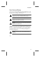
Notes, Cautions, and Warnings
Always use care when handling any electrical equipment. To avoid
injury to people or damage to equipment and data, be sure to follow
the cautions and warnings in this document.
Note: Notes are reminders, tips, or suggestions that may
simplify the procedures included in this document.
!
Caution: Cautions alert you to actions that could cause
damage to your system or your data.
WARNING: Warnings alert you to actions that could cause
injury to you or someone else.
Adaptec does not claim to have included in this document every
condition or situation that may require a caution or warning notice.
Be sure to consult the documentation for your computer and any
connected equipment when you are installing the equipment or
changing its configuration.
WARNING: Always use caution when handling electrical
equipment!
❒
1-3
▼ ▼ ▼ ▼
2
Installation
This chapter explains how to install AHA-2940UW/OF and
AHA-2944UW/OF hardware and device drivers.
WARNING: Before you begin installation, turn OFF power to
the computer and peripheral devices and disconnect the
power cords.
2-1
AHA-2940UW/OF and AHA-2944UW/OF User’s Guide
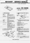
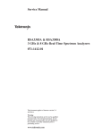
Board Layout
The AHA-2940UW/OF host adapter supports single-ended SCSI
devices. The AHA-2944UW/OF host adapter supports differential
SCSI devices. The diagrams below identify the SCSI connectors on
each host adapter.
16-bit (68-pin) Wide
Internal Connector
8-bit (50-pin) Narrow
Internal Connector
16-bit (68-pin)
Wide External Connector
AHA-2940UW/OF
16-bit (68-pin) Wide
Internal Connector
8-bit (50-pin) Narrow
Internal Connector
16-bit (68-pin)
Wide External Connector
AHA-2944UW/OF
Figure 2-1. AHA-2940UW/OF and AHA-2944UW/OF Board Locations
Note: For detailed information on mixing wide and narrow
SCSI devices, refer to the Adaptec web site Connecting 8-Bit
and 16-Bit Devices to an Adaptec Wide Host Adapter at
http://www.adaptec.com/cables/
2-2
Installation
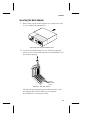
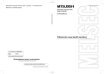
Inserting the Host Adapter
1
Remove the cover from the computer case. (If necessary, refer
to your computer documentation.)
Figure 2-2. Removing the Chassis Cover
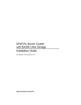
2
Locate an unused PCI expansion slot. (This slot is typically
white or ivory.) Unscrew the expansion slot bracket that covers
the card-slot opening.
PCI Slots
(usually white
or ivory)
Figure 2-3. PCI Slot Location
The PCI slot must support bus master data transfers, or the
host adapter will not work. Refer to your computer
documentation or contact your vendor.
2-3
AHA-2940UW/OF and AHA-2944UW/OF User’s Guide
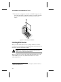
3
Insert the host adapter in a 32-bit or 64-bit PCI expansion slot.
Press it down firmly so that the contacts are securely seated in
the slot and secure it with the screw that you removed in
Step 2.
Figure 2-4. Host Adapter Installation
Installing SCSI Devices
Make sure that all SCSI devices have unique SCSI ID’s. (Refer to
your device documentation for SCSI ID settings and instructions on
manually changing the default settings.1)
Note: If your computer comes with preterminated SCSI
cables, leave all devices unterminated.
Make sure that you connect only single-ended SCSI devices to the
AHA-2940UW/OF and only differential SCSI devices to the
AHA-2944UW/OF.
1
When narrow 50 pin SCSI devices are connected, the SCSI ID of the host
adapter should be set to 7.
2-4
Installation
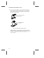
Internal SCSI Devices
1
Install or enable terminators on the device that you plan to
install at the end of the internal cable. Then remove or disable
terminators on all remaining devices.
On most internal SCSI devices, you control termination by
setting a jumper or a switch, or by physically removing or
installing a resistor module(s). Refer to the device’s
documentation to determine how to enable or disable
termination on your particular device.
This Device
Terminated
Figure 2-5. Installing Internal SCSI Devices
2
Install and mount each internal SCSI device inside your
computer. (Refer to your computer and device documentation
for instructions.)
2-5
AHA-2940UW/OF and AHA-2944UW/OF User’s Guide
3
Plug one end of the 50-pin or 68-pin internal SCSI cable into
the host adapter’s internal SCSI connector. Use a SCSI cable
with enough connectors to accommodate all of the internal
devices you want to attach.
50-pin Narrow Internal
Connection
Pin 1
68-pin Wide Internal
Connection
Pin 1
Figure 2-6. Internal Ribbon Cable Connection
Make sure that the colored stripe on one side of the cable is
aligned with pin-1 of the host adapter’s connector. Pin-1 of the
connector is usually designated by a small triangle (▲), or a “1”
on the connector.
2-6
Installation
4
Plug the other end of the internal SCSI cable into the connector
on the last internal SCSI device in the chain. This device must
be terminated. Make sure the colored stripe on the side of the
cable is aligned with pin-1 of the SCSI device’s connector.
Pin 1
Figure 2-7. SCSI Cable Connector Location
5
Plug the remaining cable connectors into any remaining
internal devices. These devices must not be terminated.
6
Connect a DC power cable from your computer’s power
supply to the power connector on the SCSI device(s).
Figure 2-8. Power Cable Connection
7
Replace the computer chassis cover.
2-7
AHA-2940UW/OF and AHA-2944UW/OF User’s Guide
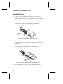
External SCSI Devices
1
Plug one end of a 68-pin external SCSI cable into the host
adapter’s external SCSI connector. Plug the other end of the
external SCSI cable into one of the connectors on the external
SCSI device.
If you are installing only one external device, enable the device
termination or attach a terminating plug to the device.
Terminating
Plug
Figure 2-9. External SCSI Device Connection
2
To connect additional external SCSI devices, daisy-chain each
device to the previous device until all devices are connected to
each other.
Terminate the device at the end of the chain by attaching a
terminating plug or enabling the onboard terminator.
Terminating
Plug
Figure 2-10. Daisy-chain Connection of External Devices
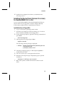
3
2-8
Reconnect the power cables to your computer and SCSI
devices. Turn the SCSI devices on, then turn the computer on.
Installation
4
Install the host adapter device driver, as described in the
following section.
Installing the Device Driver (Version 2.0 or Later)
for Solaris/SPARC 2.5.1 or 2.6
You can install AHA-2940UW/OF and AHA-2944UW/OF device
drivers either from a floppy disk or from the Adaptec Web Site.
Follow the procedures below to install the device drivers.
Installation from a Floppy Disk
1
1
Log on to the Solaris operating system as root.
2
At the superuser prompt (#), type the following command and
press Enter:
Insert the 7800 Family Open Firmware Manager Set, v2.0 device
driver installation diskette into the floppy drive.
/etc/init.d/volmgt stop
3
Then type the following and press Enter:
pkgadd -d /dev/fd0
The following software package is displayed:
1 ADPadp
Adaptec 294X(U)W/394X(U)W/4944(U)W SCSI
Host Adapter Driver
(UltraSparc) release v2.00
4
Select the package by typing 1 or all and pressing Enter to
install the device driver.
5
6
Press Y to answer yes to each question that follows.
When the following message is displayed, type q to quit the
installation:
Installation of <ADPadp> was successful.
7
Reboot the system to enable the new device driver to take
effect.
2-9
AHA-2940UW/OF and AHA-2944UW/OF User’s Guide
Installation from the Adaptec Web Site
1
2
3
4
Visit the Adaptec web sit at http://www.adaptec.com
5
6
If you are not logged on at root, re-log on as root.
Select the Products link.
Select the Sun/UltraSparc Solutions link.
Follow the links and download the latest driver onto your
system.
At the superuser prompt (#), type the following command and
press Enter:
pkgadd -d / dirname /driver.img
(where dirname is the location of the downloaded driver.img
file)
The following software package is displayed:
1 ADPadp
Adaptec 294X(U)W/394X(U)W/4944(U)W SCSI
Host Adapter Driver
(UltraSparc) release v2.00
7
Select the package by typing 1 or all and pressing Enter to
install the device driver.
8
9
Press Y to answer yes to each question that follows.
When the following message is displayed, type q to quit the
installation:
Installation of <ADPadp> was successful.
10
2-10
Reboot the system to enable the new device driver to take
effect.
Installation
Configuring SCSI Devices
Your host adapters can transfer data up to 40 MBytes per second on
each SCSI channel when connected to devices on a wide bus that
support UltraSCSI. UltraSCSI and non-UltraSCSI devices can coexist
on the same cable, and each device can transfer data at its own
negotiated or assigned transfer rate. However, to reliably transfer
data at the higher transfer rate of UltraSCSI, the following
requirements must be met:
■
Internal and external cables must be terminated with active
teminators, either provided by the SCSI device at the end of the
cable or by a separate terminating plug. The terminators on the
AHA-2940UW/OF and AHA-2944UW/OF are active
terminators.
■
For all SCSI devices connected to the host adapter, make sure
you use high-quality SCSI cables to ensure reliable data
transfer.
■
When four or more UltraSCSI devices are connected to the host
adapter, the combined length of all cables (internal and
external) must not exceed 1.5 meters for single-ended devices
or 25 meters for differential devices to ensure reliable
operation.
If fewer than four UltraSCSI devices are used the combined
cable length must not exceed 3.0 meters for single-ended
devices or 25 meters for differential devices.
2-11
AHA-2940UW/OF and AHA-2944UW/OF User’s Guide
Troubleshooting Checklist
If you have any problems during the installation, check the
following items first:
■
Are the power cables and SCSI cables properly connected?
■
Is the host adapter firmly seated and secured in the PCI
expansion card slot?
■
Does each SCSI device including the host adapter, have a
unique SCSI ID?
■
Is SCSI termination set correctly?
If you still haven’t resolved your problem, read on.
If your computer hangs or the host adapter cannot always find the
SCSI devices
■
Be sure SCSI termination is set correctly.
■
Check cable length and integrity.
■
After a hang, turn OFF your computer and any devices
connected to it, and then turn the devices and computer ON
again to reset the SCSI bus.
■
Try another PCI slot.
❒
2-12
▼ ▼ ▼ ▼
3
Using SCSISelect
The SCSISelect utility enables you to change host adapter and SCSI
configuration settings directly from your computer’s desktop.
SCSISelect also contains utilities that allow you to low-level format
or verify the disk media of your SCSI hard disk drives.
You can use SCSISelect directly from the P1275 User Interface.
Selecting a Single-Chip Host Adapter with the
P1275 User Interface
To select a single-chip host adapter with the P1275 User Interface:
1
2
Enter the system’s Forth evaluator.
To display a list of attached devices, type the following
command at the ok prompt (also known as the Forth prompt,
Forth evaluator, or ROM monitor):
show-devs
3
From the ok prompt, select the Adaptec single-chip host
adapter to be configured. The word select is used to establish a
device instance for the adapter. For example, to select a singlechip host adapter, type the following command:
select /pci/pci@2/scsi@4
Some systems may allow abbreviated forms of the device path
name for selection, for example:
select /pci/@2/@4
3-1
AHA-2940UW/OF and AHA-2944UW/OF User’s Guide
4
To verify the selection, type the following command at the ok
prompt:
pwd
5
To view the configuration properties of any selected singlechip host adapter, type the following command at the ok
prompt:
.properties
6
To obtain firmware release and copyright information, type the
following at the ok prompt:
release
copyright
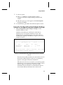
Executing the SCSISelect Utility
At the ok prompt enter the following command:
scsiselect
The first screen is the SCSISelect Options screen which displays
options, one line at a time. Two options are available to you:
■
Configure/View Host Adapter Settings
■
SCSI Disk Utilities
To select an option, use the ↑ and ↓ keys or Spacebar to display
the option, then press Enter. To exit SCSISelect, press Esc.
A screen similar to the one in Figure 3-1 appears:
AHA-294XU/UW/D
SCSISelect(R) Utility
v1.06
Copyright(c) 1996-1998 Adaptec, Inc. All rights reserved
------------------[
SCSISelect Options
]------------------
Do you wish to configure the host adapter or run the SCSI disk
utilities?
{<Space> to select option
<Enter> to accept option
<Esc> to exit}
Select Option: [Configure/View Host Adapter Settings]
Figure 3-1. SCSISelect Options Screen
3-2
Using SCSISelect
1
To select an option
■
■
2
Press ↑, ↓, or Space to scroll through the options:
Configure/View Host Adapter Settings and SCSI Disk
Utilities.
When the option you want appears at the Select Option
prompt, press Enter.
To exit SCSISelect, press Esc in the SCSISelect Options screen.
Using the Configure/View Host Adapter Settings
1
Select Configure/View Host Adapter Settings from the
SCSISelect Options screen.
SCSISelect scans the device’s PCI bus for other devices
identical to the one selected. If SCSISelect locates other
identical devices, the utility displays a list of these devices,
including the originally selected device. Figure 3-2 shows an
example of this list.
-------------[ Configure/View Host Adapter Settings ]-------------------------[ AHA-294XU/UW/D - Bus
Name
AHA-294XU/UW/D
pci9004,8178
Model
ADPT,AIC-7881
ADPT,AIC-7881
{<Space> to select device
1 - Device 4 ]-------------
Bus
1
1
Device
4 (active)
5
<Enter> to accept device
<Esc> to exit}
Select Host Adapter to Configure: [Device 4]
Figure 3-2. Configure/View Host Adapter Settings Screen for Identical
Devices
The device from which SCSISelect was activated is shown in
the header. Additionally, the word active, in parenthesis,
appears to the right of the device information.
When the active device is reset (which occurs during system
initialization), various device configuration settings, such as
initiator support for Wide SCSI or automatic cable
termination, may be altered to accommodate the device’s
environment. Because SCSISelect does not know the
3-3
AHA-2940UW/OF and AHA-2944UW/OF User’s Guide
environment of the other devices, the utility must make
assumptions for configuration settings based on the active
device.
To select a device
■
Press ↑, ↓, or Space to scroll among the list of devices.
■
When the device you want to configure appears at the
Select Host Adapter to Configure prompt, press Enter.
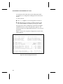
The top portion of the configuration screen (Host Adapter
SCSI ID and above) for the selected device appears. The
remaining options are displayed line-by-line as you set each
parameter.
Figure 3-3 shows the complete configuration screen for the
selected device.
--------------[AHA-294XU/UW/D - Bus
{<Space> to select settings
{<Enter> to accept setting
{!=select default setting
{@=select saved setting
{#=select previous setting
1 - Device 4]--------------
<Tab> to select device
<Esc> to abort configuration
F6=restore all default settings
F7=restore all saved settings
F8=restore all previous settings
Host Adapter SCSI ID .......................... [
7
SCSI Parity Checking ..................... [
ENABLED
Support for Ultra SCSI Speed.............. [
ENABLED
Host Adapter SCSI Termination ............ [ AUTOMATIC
Initiate Sync Negotiation -- SCSI ID [
0] [
YES
Maximum Sync Transfer Rate - SCSI ID [
0] [
40.0
Enable Disconnection ------- SCSI ID [
0] [
YES
Initiate Wide Negotiation -- SCSI ID [
0] [
YES
Reset SCSI Bus at Host Adapter Initialization [
YES
]
]
]
]
]
]
]
]
]
}
}
}
}
}
(default)
(default)
(default)
(default)
(default)
(default)
(default)
(default)
(default)
*Do you wish to save your settings? .... [ YES ] ..settings saved
Do you wish to reboot the system? ..... [ NO ]
Do you wish to reinitialize the device? [ YES ] . device reinitialized
Figure 3-3. Device Configuration Screen
3-4
Using SCSISelect
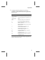
2
Use the keys listed in the table below for the device
configuration screen. Alternate keys, where possible, are
provided for terminal emulators that do not support certain
keyboard inputs.
Key
Function
↑ or ↓
Alternate: Space
← or →
Alternate: Tab
Scrolls through the settings of an option.
Enter
Accepts the setting for the selected device.
?
For some fields, displays a help screen.
Esc
Returns to the SCSISelect Options menu or
aborts an operation.
!
Restores the default setting for the currently
displayed option.
@
Restores the last-saved setting for the
currently displayed option.
#
Restores the previous setting for the
currently displayed option.
F61
Restores all default settings on the device
configuration screen.
F71
Restores all last-saved settings on the device
configuration screen.
F81
Restores all previous settings on the device
configuration screen.
Scrolls through the devices (SCSI IDs) of an
option.
1 If
your keyboard does not support F6, F7, and F8, use !, @, and # to restore
settings. To restore settings for an option you set previously, press Esc and
begin the configuration process again.
3-5
AHA-2940UW/OF and AHA-2944UW/OF User’s Guide
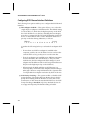
Configuring SCSI Channel Interface Definitions
The following four options enable you to configure the SCSI channel
interface:
■
Host Adapter SCSI ID— This option allows you to select the
single-chip host adapter’s SCSI Initiator ID. The default setting
for all models is 7, which has the highest priority on the SCSI
bus. Each SCSI device on the bus, including the host adapter,
must have a unique SCSI ID. The SCSI ID identifies each SCSI
device on the SCSI bus and is used to determine the device’s
priority on the bus during arbitration, as follows:
Highest
Lowest
7 6 5 4 3 2 1 0 15 14 13 12 11 10 9 8
Consider the following before you select the host adapter SCSI
ID:
– If more than one SCSI host adapter is installed in the
computer, each has its own SCSI bus. Devices can have the
same SCSI IDs as long as they are not on the same bus.
– If two host adapters are installed in two different computers
and are attached to the same SCSI bus so they can share
SCSI devices, the Host Adapter SCSI ID settings for each
adapter must be different. (IDs 6 and 7 are preferred because
they have the highest priority on the SCSI bus.)
– When using both Wide and Narrow SCSI devices, it is
necessary that you limit the Host Adapter SCSI ID setting to
0 through 7 because using SCSI Initiator IDs of greater than
7 will preclude host adapter reselection by Narrow devices.
■
3-6
SCSI Parity Checking— This option enables or disables SCSI
parity checking. The single-chip host adapter always checks
parity when reading from the SCSI bus to verify the correct
transmission of data from the attached SCSI devices. Set SCSI
Parity Checking to Disabled only if any attached devices do
not support SCSI parity. The default setting is Enabled.
Using SCSISelect
■
Support for UltraSCSI Speed— This option determines
whether the single-chip host adapter negotiates for doublespeed synchronous transfer rates in support of UltraSCSI
devices on the selected SCSI bus. The setting of this option
affects the values displayed for the Maximum Sync Transfer
Rate option available for each SCSI device on the SCSI bus.
■
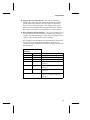
Host Adapter SCSI Termination— This option enables you to
configure the SCSI cable termination on the single-chip host
adapter. The default setting for single-chip host adapters that
support cable-sensing termination is Automatic.
Host Adapter SCSI Termination is determined by which SCSI
connectors on the single-chip host adapter have devices
attached to them. The Manual termination settings are listed in
the table below:
Single-Chip Host Adapter
Termination
LOW
HIGH
Devices Attached To…
ON
ON
68-pin internal connector only
ON
ON
68-pin external connector only
ON
ON
50-pin internal connector only
OFF
OFF
68-pin internal and 68-pin external
connectors
OFF
ON
50-pin and 68-pin internal
connectors
OFF
ON
50-pin internal and 68-pin external
connectors
INVALID
1 You cannot connect devices to
50-pin and 68-pin internal
connectors and 68-pin external
connector1
all three connectors at the same time.
3-7
AHA-2940UW/OF and AHA-2944UW/OF User’s Guide
SCSI Device Configuration
The next four options allow you to configure certain parameters for
each SCSI device on the SCSI bus. The settings apply to all SCSI IDs,
even if they have not been assigned to a device. If you are
configuring the active device, use the SCSI Disk Utilities option,
which is explained on page 3-10, to determine which SCSI IDs are
assigned to which devices.
■
Initiate Sync Negotiation— This option determines if the
single-chip host adapter initiates synchronous negotiation
with each SCSI device. When Initiate Sync Negotiation is set to
Yes, the single-chip host adapter initiates synchronous
negotiation with the SCSI device. When the option is set to No,
the single-chip host adapter does not initiate synchronous
negotiation. The default setting is Yes for all SCSI devices
because most SCSI devices support synchronous negotiation
and because a Yes setting may allow faster data throughput.
The single-chip host adapter always responds to synchronous
negotiation if the SCSI device initiates it; however, data is
transferred in asynchronous mode if neither the single-chip
host adapter nor the SCSI peripheral negotiates for
synchronous data transfers.
Note: Some older SCSI-1 devices do not support
synchronous negotiation while Initiate Sync Negotiation is
set to Yes, causing the computer to operate erratically or
hang. If you use these devices, set Initiate Sync Negotiation
to No.
■
Maximum Sync Transfer Rate— This option determines the
maximum synchronous data transfer rate that the single-chip
host adapter can support for a given device. The single-chip
host adapter supports rates up to the UltraSCSI maximum of
20.0 MB/sec. UltraSCSI host adapters attached to a Wide SCSI
bus support an effective maximum synchronous transfer rate
of 40.0 MB/sec. The default setting is the maximum rate
supported by the single-chip adapter:
– 40.0 MB/sec for Wide UltraSCSI
– 20.0 MB/sec for Narrow UltraSCSI or Wide SCSI
3-8
Using SCSISelect
– 10.0 MB/sec for Narrow SCSI
If the single-chip host adapter is configured so it will not
initiate synchronous data transfers (Initiate Sync Negotiation is
set to No), the maximum synchronous transfer rate is the
maximum rate the single-chip host adapter accepts from the
device during negotiation.
■
Enable Disconnection— This option determines whether the
single-chip host adapter will allow the SCSI device to
disconnect from the SCSI bus. When Enable Disconnection is
set to Yes, the single-chip host adapter can perform other
operations on the SCSI bus while the SCSI device is
temporarily disconnected. The default setting is Yes.
■
Initiate Wide Negotiation— This option determines whether
the single-chip host adapter attempts 16-bit data transfers
(Wide Negotiation) instead of 8-bit data transfers. The default
setting is Yes. (The Initiate Wide Negotiation option is only
displayed if the single-chip host adapter is connected to a Wide
SCSI bus.)
When Initiate Wide Negotiation is set to Yes, the single-chip
host adapter attempts 16-bit data transfers with the device.
When the option is set to No, the single-chip host adapter
performs 8-bit data transfers unless the SCSI device itself
requests Wide Negotiation.
Note: If you use 8-bit SCSI devices that have trouble
handling Wide Negotiation while Initiate Wide
Negotiation is set to Yes, the computer may operate
erratically or hang. If you use these devices, set Initiate
Wide Negotiation to No.
Advanced Configuration
■
Reset SCSI Bus at Host Adapter Initialization— This option
allows you to enable or disable SCSI bus resets generated by
the single-chip host adapter during power-on initialization
and after a hard reset. The default setting is Yes. In most cases,
Reset SCSI Bus at Host Adapter Initialization should be set to
Yes.
3-9
AHA-2940UW/OF and AHA-2944UW/OF User’s Guide
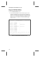
Using the SCSI Disk Utilities
To use the SCSI Disk Utilities option
1
Select SCSI Disk Utilities from the SCSISelect Options screen.
SCSISelect immediately scans the active device’s SCSI bus for
all devices connected to the single-chip host adapter. SCSISelect
displays a list of all SCSI IDs and the devices assigned to them.
Figure 3-4 shows an example of a SCSI Disk Utilities target
selection screen.
-------------[
SCSI
SCSI
SCSI
SCSI
SCSI
SCSI
SCSI
SCSI
SCSI
SCSI
SCSI
SCSI
SCSI
SCSI
SCSI
SCSI
ID:
ID:
ID:
ID:
ID:
ID:
ID:
ID:
ID:
ID:
ID:
ID:
ID:
ID:
ID:
ID:
0
1
2
3
4
5
6
7
8
9
10
11
12
13
14
15
-
SCSI Disk Utilities
No Device
No Device
No Device
No Device
Disk
No Device
No Device
Host Bus Adapter
No Device
No Device
No Device
No Device
No Device
No Device
No Device
No Device
{<Space> to select device
Select Target: [SCSI ID:
]--------------
-CONNER CFP1060W
-AHA-294XU/UW/D
-
<Enter> to accept device
0-No Device
<Esc> to exit}
]
Figure 3-4. SCSI Disk Utilities Target Selection Screen
3-10
Using SCSISelect
2
3
Use the keys listed in the table below for the SCSI Disk Utilities
target selection screen as follows. Alternate keys, where
possible, are provided for terminal emulators that do not
support certain keyboard inputs:
Key
Function
↑ or ↓
Alternate: Space
Scrolls through the list of SCSI IDs.
Enter
Accepts the setting for the selected device.
Esc
Returns to the SCSISelect Options screen,
returns to the Target Selection screen, or
aborts an operation.
?
For some fields, displays a Help screen.
To select a device
a Press ↑, ↓, or Space to scroll through the list of devices.
b When the device you want appears at the Select Target
prompt, press Enter.
If you select an invalid entry, a message appears advising you
of the problem.
– Press Esc to return to the SCSISelect Options screen
or
– Press any other key to return to the SCSI Disk Utilities
Target Selection screen
Once a valid device is selected and accepted, SCSISelect
displays the selection and asks if you want to format or verify
the device, as in Figure 3-5.
SCSI ID:
4 UNIT:
0-Disk
-CONNER CFP1060W
Do you wish to format or verify the device? [VERIFY]
Figure 3-5. Format or Verify Device Screen
3-11
AHA-2940UW/OF and AHA-2944UW/OF User’s Guide
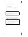
4
Select Verify or Format.
These options are explained in the following sections.
Using the Verify SCSI Disk Media Utility
To use the Verify [SCSI disk media] utility
1
Select Verify.
A safety prompt appears to verify the selection (Figure 3-6).
-----------------------------Verify----------------------------This drive will be scanned for media defects. All recoverable defects
will be remapped. Once started, media verification may be aborted at
any time by pressing the <Esc> key.
Press <Enter> to initiate; <Esc> to abort
Figure 3-6. Verify Message Screen—Executing the Utility
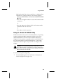
2
To execute the utility, press Enter; to discontinue, press Esc.
The Verify utility sequentially scans the selected device’s
media for defects. A screen similar to the one in Figure 3-7
appears.
-----------------------------Verify----------------------------This drive will be scanned for media defects. All recoverable defects
will be remapped. Once started, media verification may be aborted at
any time by pressing the <Esc> key.
SCSI ID: 4 UNIT: 0-Disk
-CONNER CFP1060W
Capacity: 2074880 blocks-Block Size: 512 bytes
Verifying...20% complete-block 417792
Figure 3-7. Verify Message Screen— Defect Scanning in Progress
3-12
Using SCSISelect
If the Verify utility finds a Recovered Error or a Medium Error
on the device, a message similar to the following appears:
Verifying...ERROR-sector 417792 has a defect-REASSIGN
BLOCK?
– Press Y to reassign the defective sector and continue media
verification
or
– Press N to ignore the defective block and continue media
verification with the next sector
or
– Press Esc to abort the operation
Using the Format SCSI Disk Utility
Fixed data media must be low-level formatted before an operating
system’s partitioning and file preparation utilities can be used.
(Most SCSI disk drives are low-level formatted at the factory.)
Adaptec’s Format utility is compatible with most SCSI disk drives.
Use the Format utility to format hard disk drives or removablemedia drives that were previously used with non-Adaptec host
adapters.
!
Caution: Low-level formatting destroys all the data on a disk
drive. Be sure to back up any data you want to keep before
you low-level format your drive. Once started, a low-level
disk format cannot be aborted.
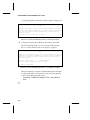
To use the Format [SCSI disk] utility
1
Select the Format option from the Format or Verify Device
screen (see Figure 3-5 on page 3-11).
3-13
AHA-2940UW/OF and AHA-2944UW/OF User’s Guide
A safety prompt that verifies the selection appears (Figure 3-8).
------------------------------Format------------------------------
WARNING!!! This drive is about to be low-level formatted. All data on
the disk will be erased. Depending on your disk capacity, formatting
may take from several seconds to several hours, and once started,
cannot be aborted.
Press <Enter> to initiate; <Esc> to abort
Figure 3-8. Format Utility Message Screen— Executing the Utility
2
To begin formatting, press Enter; to discontinue, press Esc.
The Format utility begins to low-level format the hard disk
drive. A screen similar to the one in Figure 3-9 appears.
------------------------------Format------------------------------
WARNING!!! This drive is about to be low-level formatted. All data on
the disk will be erased. Depending on your disk capacity, formatting
may take from several seconds to several hours, and once started,
cannot be aborted.
SCSI ID: 4 UNIT: 0-Disk
-CONNER CFP1060W
Capacity: 2074880 blocks-Block Size: 512 bytes
Formatting...Please Wait
Figure 3-9. Format Utility Message Screen— Formatting in Progress
When formatting is complete, all intermediate keyboard inputs
are discarded and a message similar to the following appears
in the Format utility message screen:
Formatting...COMPLETE-Elapsed Time: 1 Hrs 6 Mins 53
Secs
❒
3-14
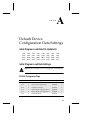
A
▼ ▼ ▼ ▼
Default Device
Configuration Data Settings
Initial Program Load Data File (ipldata.fc)
1802
3802
B618
FFFF
1802
3802
5C00
FFFF
1802
3802
0728
FFFF
1802
3802
0800
FFFF
1802
3802
00FF
FFFF
1802
3802
FFFF
FFFF
1802
3802
FFFF
FF00
1802
3802
FFFF
9763
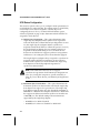
Initial Program Load Data Settings
Note: Fields in shaded rows are configurable via SCSISelect.
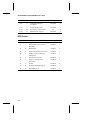
SCSI ID Configuration Flags
Offset
Bits
Title
Setting
Value
0–15
0–2
Transfer Rate
10 MHz
000
0–15
3
Synchronous Negotiation
Enabled
1
0–15
4
SCSI Disconnection
Enabled
1
0–7
5
Initiate Wide SCSI Negotiation
Disabled
0
8–15
5
Initiate Wide SCSI Negotiation
Enabled
1
0–15
6
UltraSCSI Mode
Disabled
0
A-1
AHA-2940UW/OF and AHA-2944UW/OF User’s Guide
Offset
Bits
Title
Setting
Value
0–15
8
Send Start Unit SCSI
Command
Disabled
0
0–15
9
Include In BIOS Scan
Disabled
1
0–15
10
Report Even If Not Found
0–15
11
Multiple LUN Support
No
0
Disabled
0
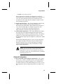
BIOS Control
Offset
A-2
Bits
Title
Setting
Value
16
0
Support All Removable Drives
Disabled
0
16
1
Support Removable Drive for
Boot Only
Enabled
1
16
2
BIOS Enable
Enabled
1
16
4
Support More Than Two Drives
Enabled
1
16
5
Display <Ctrl-A> Message
During Boot
Enabled
1
16
6
Virtual DMA Services
Disabled
0
16
7
Support >1 GByte Drive
Translation
Enabled
1
16
8
SCAM
Disabled
0
16
11
Bootable CD-ROM Support
Enabled
1
16
12
INT13 Extensions
Enabled
1
Default Device Configuration Data Settings
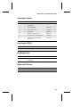
Host Adapter Control
Offset
Bits
Setting
Value
17
0
Automatic Cable Sensing
Termination
Title
Disabled
0
17
1
UltraSCSI Mode
Disabled
0
17
2–3
SCSI Termination
Enabled
11
17
4
SCSI Parity
Enabled
1
17
5
Multiple LUN Support
Disabled
0
17
6
Reset SCSI Bus at Initialization
Enabled
1
17
7
Automatic Current Sensing
Termination
Disabled
0
Setting
Value
7
0111
Host Adapter SCSI ID
Offset
Bits
Title
18
0–3
Host Adapter SCSI ID
Bus Release Time
Offset
Bits
Title
18
8–15
Bus Release Time After
Preempt
Setting
Value
40
00101000
Setting
Value
8
00001000
Maximum # of Devices
Offset
Bits
Title
19
0–7
Maximum # of Devices
A-3
AHA-2940UW/OF and AHA-2944UW/OF User’s Guide
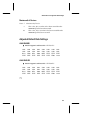
Reset Initialization Default Data Adjustments
SCSI ID Configuration Flags
Wide
Bit 5
Initiate Wide SCSI Negotiation
0
This bit is cleared (DISABLED) for SCSI IDs 0 through
7 when it has been sensed that the WIDEPS# input has
been deasserted.
1
This bit is set (ENABLED) for all SCSI IDs when it has
been sensed that the WIDEPS# input has been asserted.
Host Adapter Control
Fast-20
Bit 1
UltraSCSI Mode
0
This bit is cleared (DISABLED) when the GND/REXT
pin is sensed as being tied to ground.
1
This bit is set (ENABLED) when the GND/REXT pin is
sensed as having an external precision resistor
present.
Autotermination
Bit 0
Bit 7
Automatic Cable-Sensing Termination
0
This bit is cleared (DISABLED) for products that do
not support automatic cable-sensing termination.
1
This bit is set (ENABLED) for products that support
automatic cable-sensing termination.
Automatic Current-Sensing Termination
0
A-4
This bit is always cleared (DISABLED).
Default Device Configuration Data Settings
Maximum # of Devices
Bits 0– 7
Maximum # of Devices
8
This value, 8, is set when it has been sensed that the
WIDEPS# input has been deasserted.
10
This value, 16, is set when it has been sensed that the
input has been asserted.
WIDEPS#
Adjusted Default Data Settings
AHA-2940UW
■
Initial Program Load Data File—IPL7881.FC
3802
3802
B618
FFFF
3802
3802
5F00
FFFF
3802
3802
0728
FFFF
3802
3802
1000
FFFF
3802
3802
00FF
FFFF
3802
3802
FFFF
FFFF
3802
3802
FFFF
FF00
3802
3802
FFFF
A264
AHA-294XUW
■
Initial Program Load Data File—IPL7884.FC
3802
3802
B618
FFFF
3802
3802
5F00
FFFF
3802
3802
0728
FFFF
3802
3802
1000
FFFF
3802
3802
00FF
FFFF
3802
3802
FFFF
FFFF
3802
3802
FFFF
FF00
3802
3802
FFFF
A264
❒
A-5
▼ ▼ ▼ ▼
A
Advanced configuration 3-9
AHA-2940UW/OF and
AHA-2944UW/OF
illustrated 2-2
Autotermination settings A-4
Index
Device configuration 3-8
screen illustration 3-4
Device Driver
installation 2-9
E
B
Enable disconnection option 3-9
BIOS control settings A-2
Bus release time settings A-3
F
Fast-20 settings A-4
C
Caution notice, explanation of 1-3
Command
properties 3-2
pwd 3-2
select 3-1
show-devs 3-1
Configuration
advanced 3-9
SCSI channel interface 3-6
Configuring SCSI devices 2-11
Conventions 1-2
Copyright information for
device 3-2
D
Default settings
initial program load data A-1
initial program load data file
(ipldata.fc) A-1
reset initialization default data
adjustments A-4
Format disk utility
low-level format destroys data
and cannot be aborted 3-13
Format SCSI disk utility 3-13
Forth evaluator, See OK prompt
Forth prompt, See OK prompt
G
gnd/rext pin A-4
H
Host adapter
autotermination A-4
control settings A-3, A-4
Fast-20 A-4
SCSI ID 3-6
SCSI ID settings A-3
SCSI termination 3-7
single-chip with the P1275 user
interface 3-1
Index-1
AHA-2940UW/OF and AHA-2944UW/OF User’s Guide
I
R
Initial program load data
ipldata.fc A-1
Initial program load data
settings A-1, A-3
BIOS control A-2
bus release time A-3
host adapter SCSI ID A-3
maximum # of devices A-3
SCSI ID configuration flags A-1
Initiate sync negotiation 3-8
Initiate wide negotiation 3-9
Installation
device driver (v.2.0) 2-9
external SCSI devices 2-8
host adapter 2-3
internal SCSI devices 2-5
troubleshooting 2-12
Release information for device 3-2
Reset initialization
default data adjustments A-4
host adapter control A-4
SCSI ID configuration flags A-4
Reset SCSI bus at host adapter
initialization option 3-9
ROM monitor, See OK prompt
M
Maximum # of devices A-3
settings A-5
Maximum sync transfer rate
option 3-8
N
note, explanation of 1-3
P
P1275 user interface 3-1
Pin
gnd/rext A-4
wideps# A-4
Power connection
to SCSI devices 2-7
Properties command 3-2
pwd command 3-2
Index-2
S
SCSI channel interface,
configuring 3-6
SCSI device configuration 3-8
SCSI disk utilities 3-10
format SCSI disk utility 3-13
target selection screen,
illustrated 3-10
verify SCSI disk media
utility 3-12
SCSI ID configuration flags A-1, A-4
wide setting A-4
SCSI parity checking option 3-6
SCSISelect
configure/view host adapter
settings 3-3
enable disconnection 3-9
executing 3-2
host adapter SCSI ID 3-6
host adapter SCSI
termination 3-7
illustrated options 3-2
initiate sync negotiation 3-8
initiate wide negotiation 3-9
maximum sync transfer rate 3-8
reset SCSI bus at host adapter
initialization 3-9
SCSI disk utilities 3-10
SCSI parity checking 3-6
See also individual options by
name
Index
Select
command 3-1
purpose of the word 3-1
Selecting a single-chip host adapter
to configure
with the P1275 user interface 3-1
V
Verify SCSI disk media utility 3-12
View host adapter settings 3-3
View host adapter settings screen,
illustrated 3-3
Show-devs command 3-1
W
T
Warning notice, explanation of 1-3
Wide setting A-4
wideps# pin A-4
Troubleshooting
problems with installing host
adapter 2-12
Typographic conventions 1-2
❒
Index-3