1
Mitsubishi Programmable Logic Controller Training Manual
Ethernet course(Q-series)
Mitsubishi Programmable
Logic Controller
Ethernet course(Q-series)
Training Manual
Ethernet course(Q-series)
MODEL
SCHOOL-Q-ETHERNET-E
MODEL
CODE
13JW51
SH(NA)-080618ENG-A(0601)MEE
HEAD OFFICE : TOKYO BUILDING, 2-7-3 MARUNOUCHI, CHIYODA-KU, TOKYO 100-8310, JAPAN
NAGOYA WORKS : 1-14 , YADA-MINAMI 5-CHOME , HIGASHI-KU, NAGOYA , JAPAN
When exported from Japan, this manual does not require application to the
Ministry of Economy, Trade and Industry for service transaction permission.
Specifications subject to change without notice.
SAFETY PRECAUTIONS
(Always read these instructions before the exercise.)
When designing the system, always read the relevant manuals and give sufficient consideration to safety.
During the exercise, pay full attention to the following points and handle the product correctly.
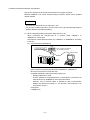
[EXERCISE PRECAUTIONS]
WARNING
Do not touch the terminals while the power is on to prevent electric shock.
When opening the safety cover, turn off the power or conduct a sufficient check of safety before
operation.
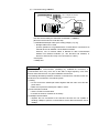
Caution
Follow the instructor's direction during the exercise.
Do not remove the module of the demonstration machine or change wirings without permission.
Doing so may cause failures, malfunctions, personal injuries and/or a fire.
Turn off the power before installing or removing the module.
Failure to do so may result in malfunctions of the module or electric shock.
When the demonstration machine (X/Y table, etc.) emits abnormal odor/sound, press "Power switch" or
"Emergency switch" to turn off.
When a problem occurs, notify the instructor as soon as possible.
A-1
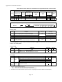
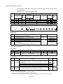
REVISIONS
* The text number is given on the bottom left of this textbook.
Print date
* Textbook number
Jan., 2006
SH-080618ENG-A First edition
Revision
This textbook confers no industrial property rights or any rights of any other kind, nor does it confer any patent licenses.
Mitsubishi Electric Corporation cannot be held responsible for any problems involving industrial property rights which may
occur as a result of using the contents noted in this textbook.
© 2006 MITSUBISHI ELECTRIC CORPORATION
A-2
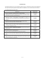
INTRODUCTION
This textbook explains how to use the Ethernet module QJ71E71 of MELSEC-Q series and its programming.
Use a personal computer applicable to Microsoft
R
Visual Basic
R
6.0 as an external device for exercises.
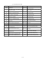
The related manuals are shown below.
Manual number
Manual name
(Model code)
Q Corresponding Ethernet Interface Module User's Manual (Basic)
Explains the specification of the Ethernet module, the data communication procedure with
target device, the line connection (open/close), the fixed buffer communication, the random
access buffer communication, and the troubleshooting.
SH-080009
(13JL88)
Q Corresponding Ethernet Interface Module User's Manual (Application)
Explains the e-mail function of Ethernet module, the PLC CPU status monitoring function, the
communication function via MELSECNET/H, MELSECNET/10, as well as the
communication function using the data link instructions, and how to use the file transfer (FTP
server), etc.
Q Corresponding Ethernet Interface Module User's Manual (Web function)
Explains how to use the Web function of the Ethernet module.
SH-080010
(13JL89)
SH-080180
(13JR40)
Q Corresponding MELSEC Communication Protocol Reference Manual
Explains the communication methods and control procedures through the MC protocol for
the external devices to read and write data from/to the PLC CPU using the serial
communication module/Ethernet module.
MX Component Version 3 Operating Manual (Startup)
Explains the procedures for installing and uninstalling MX Component and for browsing the
operating manual.
MX Component Version 3 Operating Manual
SH-080008
(13JF89)
SH-080270
(13JU31)
SH-080271
Explains the setting and operating methods of each utility on MX Component.
MX Component Version 3 Programming Manual
Explains the programming procedures, detailed descriptions and error codes of the Active X
control.
GX Developer Version 8 Operating Manual
Explains the functions such as the program creating method, printout method, monitoring
method and debug method on GX Developer.
A-3
(13JU32)
SH-080272
(13JF66)
SH-080373E
(13JU41)
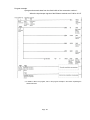
CONTENTS
SAFETY PRECAUTIONS...............................................................................................................................A- 1
REVISIONS .....................................................................................................................................................A- 2
INTRODUCTION.............................................................................................................................................A- 3
CONTENTS.....................................................................................................................................................A- 4
About the Generic Terms and Abbreviations .................................................................................................A- 7
CHAPTER 1 BASICS OF ETHERNET NETWORK
1- 1 to 1-12
1.1 Ethernet ................................................................................................................................................... 1- 1
1.2 Addresses................................................................................................................................................ 1- 2
1.2.1 MAC address (Ethernet address)................................................................................................. 1- 2
1.2.2 IP address ..................................................................................................................................... 1- 3
1.3 Communication Protocol......................................................................................................................... 1- 6
1.3.1 Communication model.................................................................................................................. 1- 6
1.3.2 IP protocol ..................................................................................................................................... 1- 8
1.3.3 TCP and UDP ............................................................................................................................... 1- 9
1.4 MELSEC-Q Ethernet Module ................................................................................................................ 1-11
1.4.1 Role of Ethernet module.............................................................................................................. 1-11
1.4.2 Outline of Ethernet module.......................................................................................................... 1-12
CHAPTER 2 BEFORE USING ETHERNET MODULE
2- 1 to 2-24
2.1 Two Data Codes...................................................................................................................................... 2- 1
2.2 Types of Data Communication Functions .............................................................................................. 2- 3
2.2.1 Communication using MC protocol .............................................................................................. 2- 3
2.2.2 Fixed buffer communication ......................................................................................................... 2- 6
2.2.3 Communication using random access buffer .............................................................................. 2- 9
2.2.4 Communicability with external devices for each data communication function......................... 2-10
2.3 Open/Close Processing ......................................................................................................................... 2-11
2.3.1 Active open/close processing...................................................................................................... 2-17
2.3.2 Passive open/close processing................................................................................................... 2-19
2.3.3 UDP/IP open/close processing ................................................................................................... 2-22
CHAPTER 3 SYSTEM CONFIGURATION
3- 1 to 3- 4
3.1 Applicable Systems................................................................................................................................. 3- 1
3.2 Devices Required for Network Configuration......................................................................................... 3- 2
CHAPTER 4 SPECIFICATIONS OF ETHERNET MODULE & SETTINGS AND PROCEDURES PRIOR TO
OPERATION
4- 1 to 4-18
4.1
4.2
4.3
4.4
4.5
4.6
4.7
Performance Specifications .................................................................................................................... 4- 1
Ethernet Module Function List ................................................................................................................ 4- 3
Settings and Procedures Prior to Starting the Operation ...................................................................... 4- 5
Components of the Ethernet Module...................................................................................................... 4- 7
Connecting to the Network...................................................................................................................... 4- 8
Settings from GX Developer ................................................................................................................... 4- 9
Self-retrain Tests .................................................................................................................................... 4-14
4.7.1 Self refrain test ............................................................................................................................. 4-14
4.7.2 Hardware test............................................................................................................................... 4-17
A-4
4.8 Mounting and Dismounting the Module................................................................................................. 4-18
CHAPTER 5 ASSIGNMENT I (MC PROTOCOL COMMUNICATION BETWEEN PC AND PLC CPU)
5- 1 to 5-38
5.1 System Configuration for Exercise ......................................................................................................... 5- 1
5.2 Parameter Settings and TCP/IP Settings for PC ................................................................................... 5- 4
5.2.1 GX Developer startup and multiple CPU setting ......................................................................... 5- 4
5.2.2 Network parameters setting the number of MNET/10H Ethernet cards ..................................... 5- 6
5.2.3 Transfer setup............................................................................................................................... 5- 9
5.2.4 Parameter write............................................................................................................................ 5-10
5.2.5 TCP/IP settings for PC................................................................................................................. 5-11
5.3 Operation of MX Component................................................................................................................. 5-13
5.3.1 Setting the logical station number ............................................................................................... 5-13
5.3.2 Communication diagnostics ........................................................................................................ 5-16
5.4 Visual Basic Program (Device Read) .................................................................................................... 5-17
5.4.1 Visual basic program ................................................................................................................... 5-17
5.4.2 Operation of demonstration machine.......................................................................................... 5-24
5.5 Visual Basic Program (Device Write) .................................................................................................... 5-29
5.5.1 Visual basic program ................................................................................................................... 5-29
5.5.2 Operation of demonstration machine.......................................................................................... 5-34
CHAPTER 6 ASSIGNMENT II (FIXED BUFFER COMMUNICATION BETWEEN PLC CPUS
(PROCEDURE EXIST))
6- 1 to 6-18
6.1 System Configuration of Exercise .......................................................................................................... 6- 1
6.2 Ethernet Module Settings on the Sending Side ..................................................................................... 6- 3
6.2.1 Setting parameters with GX Developer........................................................................................ 6- 3
6.2.2 Sequence program ....................................................................................................................... 6- 6
6.3 Ethernet Module Settings on the Receiving Side .................................................................................. 6- 9
6.3.1 Setting parameters with GX Developer........................................................................................ 6- 9
6.3.2 Sequence program ...................................................................................................................... 6-12
6.4 PING Test Using GX Developer (Via CPU) .......................................................................................... 6-14
6.5 Operation of Demonstration Machine.................................................................................................... 6-17
CHAPTER 7 ASSIGNMENT III (FIXED BUFFER COMMUNICATION BETWEEN PLC CPUS (NO
PROCEDURE))
7- 1 to 7-20
7.1 System Configuration of Exercise .......................................................................................................... 7- 1
7.2 Ethernet Module Settings (PLC A1 to A5).............................................................................................. 7- 3
7.2.1 Setting parameters with GX Developer........................................................................................ 7- 3
7.2.2 Sequence program ....................................................................................................................... 7- 6
7.3 Ethernet Module Settings (PLC B1 to B5)............................................................................................. 7-11
7.3.1 Setting parameters with GX Developer....................................................................................... 7-11
7.3.2 Sequence program ...................................................................................................................... 7-14
7.4 PING Test Using GX Developer (Via CPU) .......................................................................................... 7-18
7.5 Operation of Demonstration Machine.................................................................................................... 7-19
CHAPTER 8 ASSIGNMENT IV (FIXED BUFFER COMMUNICATION BETWEEN PLC CPUS VIA ROUTER
(NO PROCEDURE))
8- 1 to 8- 10
8.1 System Configuration of Exercise .......................................................................................................... 8- 1
8.2 Ethernet Module Settings (PLC A1 to A5).............................................................................................. 8- 2
A-5
8.2.1 Setting parameters with GX Developer........................................................................................ 8- 2
8.2.2 Sequence program ....................................................................................................................... 8- 5
8.3 Ethernet Module Settings (PLC B1 to B5).............................................................................................. 8- 6
8.3.1 Setting parameters with GX Developer........................................................................................ 8- 6
8.3.2 Sequence program ....................................................................................................................... 8- 9
8.4 PING Test from Personal Computer ..................................................................................................... 8-10
8.5 Operation of Demonstration Machine.................................................................................................... 8-10
APPENDIX
App- 1 to App-70
Appendix 1 Visual Basic Version 6.......................................................................................................... App- 1
Appendix 1.1 Startup of Visual Basic ................................................................................................ App- 1
Appendix 1.2 Outline Command ........................................................................................................ App- 4
Appendix 1.3 Term.............................................................................................................................. App- 9
Appendix 1.4 Toolbox List ................................................................................................................. App-10
Appendix 1.5 Toolbar List .................................................................................................................. App-12
Appendix 1.6 Property List ................................................................................................................ App-14
Appendix 1.7 Method List .................................................................................................................. App-19
Appendix 1.8 Function List ................................................................................................................ App-21
Appendix 2 MX Component...................................................................................................................... App-25
Appendix 2.1 Functions of MX Component ...................................................................................... App-25
Appendix 2.2 Function List ................................................................................................................ App-30
Appendix 2.3 Error Code List ............................................................................................................ App-36
Appendix 3 Connecting GX Developer to PLC CPU via Ethernet........................................................... App-46
Appendix 4 Troubleshooting ..................................................................................................................... App-49
Appendix 4.1 How to Check Errors Using LED Displays ................................................................. App-50
Appendix 4.1.1 Checking error display........................................................................................... App-50
Appendix 4.1.2 How to turn off COM.ERR. LED and to read/clear error information .................. App-52
Appendix 4.2 How to Check an Error Through GX Developer......................................................... App-53
Appendix 4.2.1 Ethernet diagnostics.............................................................................................. App-54
Appendix 4.2.2 System monitor...................................................................................................... App-55
Appendix 5 Dedicated Instructions ........................................................................................................... App-57
Appendix 5.1 Dedicated Instruction List............................................................................................ App-57
Appendix 5.2 OPEN Instruction......................................................................................................... App-58
Appendix 5.3 CLOSE Instruction....................................................................................................... App-62
Appendix 5.4 BUFSND Instruction.................................................................................................... App-65
Appendix 5.5 BUFRCV Instruction.................................................................................................... App-68
A-6
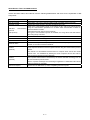
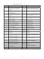
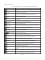
About Generic Terms and Abbreviations
Unless otherwise stated, this textbook uses the following abbreviations and terms for the explanation of MX
Component.
Generic term/Abbreviation
Description
PC CPU module
Abbreviation of PC CPU module and IBM PC/AT R compatible personal computer.
Ethernet module
Generic term of the QJ71E71, QJ71E71-B2 and QJ71E71-100.
Name of the communication system for accessing the PLC CPU from external devices
using the communication procedures for Q series serial communication modules or
Ethernet interface modules.
(Described as the MC protocol in this textbook)
Two types of communication systems are available; one using ASCII code data and the
other using binary code data.
MELSEC
communication
protocol
(MC protocol)
QJ71E71
Abbreviation of QJ71E71 type Ethernet interface module.
QJ71E71-B2
Abbreviation of QJ71E71-B2 type Ethernet interface module.
QJ71E71-100
Abbreviation of QJ71E71-100 type Ethernet interface module.
External device
Generic term for personal computers, computers, workstations (WS) and other Ethernet
module, etc. that are connected to Ethernet.
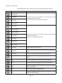
Internet
Huge computer network that connects global networks using the communication protocol
(Internet)
TCP/IP.
The Internet is a decentralized network without a computer which controls the overall
network. Also, it is established by allowing the server computers all over the world to
interconnect and provide services individually.
Intranet
Intra-corporate network that is constructed by the internet standard technology such as
(Intranet)
the communication protocol TCP/IP.
There is a specific advantage such as building an application in collaboration with internet
and the integration of operability.
Personal computer
Generic term for IBM PC/AT (or 100% compatible) personal computer.
A-7
MEMO
A-8
Chapter 1
BASICS OF ETHERNET NETWORK
Note
This textbook mainly describes how to use MELSEC-Q Series Ethernet module.
For details of general computer network technology (TCP/IP communication, etc.),
refer to commercially-available textbooks.
In addition, for details of the Ethernet module, refer to the relevant manuals.
1.1
Ethernet
The development of Ethernet was started by Xerox Palo Alto Research Center in the
U.S. in 1973, and Ethernet has been approved as a network technology by ISO and
ANSI/IEEE standards.
Lately it is widely used for networking gear and communication channel, etc. (*1)
For actual network operation, hardware technique such as transmission lines which is
defined by Ethernet (in the narrow sense) and communication technology for TCP/IP
communication (protocol: a procedure for data transmission) are necessary.
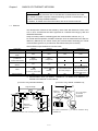
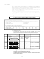
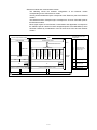
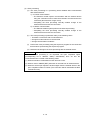
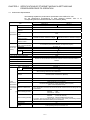
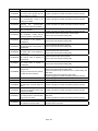
General Ethernet specifications are shown below.
Specification
10BASE5
10BASE2
10BASE-T
100BASE-TX
Data transmission speed
10 Mbps
10 Mbps
10 Mbps
100 Mbps
Maximum segment
length
500m
185m
100m
100m
Maximum network length
(or Maximum
node-to-node interval)
2500m
(5 segments)
925m
(5 segments)
Minimum node-to-node
distance
2.5m
0.5m
Cable
Coaxial 50 (12mm
diameter)
*Known as: yellow cable
Coaxial 50 (5mm
diameter)
UTP(unshielded twisted
pair cable) category 3
UTP(unshielded twisted
pair cable) category 5,
STP(unshielded twisted
pair cable) IBM Type1, 2
Network topology
Bus
Bus
Star
Star
*1 Communication lines (10 BASE-T, 10BASE-TX, 10 BASE5 and 10BASE2) are
referred to as "Ethernet" in this textbook.
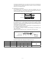
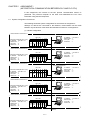
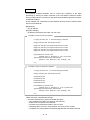
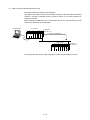
[Connection using 10BASE2/10BASE5]
[Connection using 10BASE-T/100BASE-TX]
Segment length
Hub
Node
Transceiver
Maximum
100m (5m)
Terminator
Repeater
Node
Node
Node
Maximum
node-to-node
distance
Node
Segment length
Segment length
Repeater
Maximum
100m
Up to 4 (2) stages
are allowed
for cascade
connection
E
7
1
* The value in parentheses ( ) is used for connection using
100BASE-TX.
* There is no transceiver when connecting using 10BASE2.
1-1
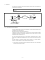
1.2
Addresses
The devices and computers connected to Ethernet must have their own addresses to
communicate on the network.
For Ethernet, the addresses which the user needs to consider are basically IP
addresses.
A's house
Postbox
Text
Photo
Mail box
Postal network
Destination
address (Address)
Destination
address (Address)
Data
Header
(Packet) Communication format
1.2.1
MAC address (Ethernet address)
The MAC address (Media Access Control Address) is a unique physical address which
is assigned to each network device.
(No other devices have the same MAC address.)
In Ethernet, it is shown as a 6-byte code: a vender code of 3 bytes (managed by IEEE
management) indicating an equipment manufacturer and a node number of 3 bytes
(managed by each manufacturer). (*1)
As each Ethernet-connected device communicates automatically getting a MAC
address from IP addresses designated by the user, the user need not be take account
of it.
The MAC address is sometimes called "Ethernet address" or "Internet address",
however, note that it differs from the IP address described below.
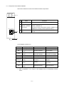
*1 MAC address of the Ethernet module is indicated in MAC ADD. of the rating plate
located on the side of the module.
1-2
1.2.2
IP address
The IP address (Internet Protocol Address) is an identification number assigned to
identify each device or computer connected to the IP network such as the Internet or
intranet. (It corresponds to a mail address or a telephone number)
Unique addresses managed by each country are used on the internet where the
network is connected on a global scale.
An IP address is expressed by a 32-bit number for IPV4, which is now used commonly.
It is generally divided into 4 parts of 8 bits like "192.168.1.1" and represented as
decimal notation.
The 32-bit value consists of the network part which identifies each network and the
host part which identifies the connected device in the network (PC, etc.)
(IP address) = ((Class) + network part address) + (host part address)
Representations of IP address
An IP address (IPv4) is described by a 32-bit number.
Binary number 00000000000000000000000000000000 to 11111111111111111111111111111111
Decimal number
0 to 4294967295
Hexadecimal number
0 to FFFFFFFF
They are divided by 8 bits for easier comprehension.
Binary number 00000000.00000000.00000000.00000000 to 11111111.11111111.11111111.11111111
Decimal number
0.
0.
0.
0 to
255.
255.
255.
255
Hexadecimal number 0.
0.
0.
0 to
FF.
FF.
FF.
FF
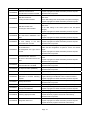
(1) Classification by class
The classification system called "class" has been traditionally used to fixedly
handle the boundary between the IP address network part and the host part .
Class
Bit assignment (*1)
Higher 8 bits
Higher bits -----------------------Lower bits
Network
part (8)
Class A
Class B
Host part (24)
7
0 Net ID
Host ID
Network part(16)
Host part(16)
1
2
1 0
24
16
Host ID
14
Net ID
Network part(24)
Class C
3
1 1 0
Boundary of
Private IP address range
network address
0*******
8 bits from the
(0 to 127)
highest
10******
16 bits from the
(128 to 191)
highest
110*****
24 bits from the
(192 to 223)
highest
10.0.0.0 to 10.255.255.255
172.16.0.0 to 172.31.255.255
Host part(8)
21
Net ID
*1 The
8
Host ID
192.168.0.0 to 192.168.255.255
part at the higher of the IP addresses indicates classes.
The classes A to C are the addresses for public use.
The address usable for the devices that are not directly connected to the Internet
is called "private IP address".
1-3
The address management was once carried out in this class unit. Nowadays the
class address with the variable-length border bit number is used for ensuring the
effective use of the address space.
(2) Management by class address
The management was once carried out in class unit. Nowadays, due to the
shortage of IP address, the class address with the variable-length network part is
used for ensuring the effective use of the address space.
Prefix length
IP address
Network part
(Sub)net mask 1111
Host part
1111 000
All 1
000
All 0
The IP address of which host part which has all 0 for the bits is a network address
(in the Ethernet unit). "/" may be added to the end of the IP address for clearly
specifying the network address length (prefix length), and also the bit length of the
network address part may be added.
The netmask is commonly used for a historical reason. The netmask has all 1 for
the network part and all 0 for the host part.
As it is divided to manage the network (sub-networking), the netmask is also
called "subnet mask".
Example: For the IP address 192.168. 10. 68 and the prefix length 26 bits
Network part (26)
Host part (6)
Binary number 11000000.10101000.00001010.01000100 / 26
Decimal number
192
. 168
. 10
. 68
/ 26
Hexadecimal number
C0
. A8
.
. 44
/ 26
A
Number
after "/" is
prefix length.
Information examples when setting the IP address to the host
Information
Address
Address value (Binary)
Remark
IP address
192.168. 10. 68/26
1100 0000
1010 1000
0000 1010
0100 0100
(Sub)net mask
255.255.255.192
1111 1111
1111 1111
1111 1111
1100 0000
Network address
192.168. 10. 64/26
1100 0000
1010 1000
0000 1010
0100 0000
Broadcast address
192.168. 10.127
1100 0000
1010 1000
0000 1010
0111 1111
1-4
Address of which host part is 1.
REMARK
Special IP addresses
(1) All bits are 0 or 1
The IP address 0.0.0.0 is used when you do not know your own IP address or it is
not necessary to inform an IP address to the target.
255.255.255.255 signifies a broadcast address (destination: all devices and PCs
connected to the same network).
(2) Loopback address
This is the address which is used between the programs executed on the same
device (PLC).
The range is from 127.0.0.0 to 127.255.255.255.
(3) Multicast address
This is the address used for communications within a specific group.
The range is from 224.0.0.0 to 239.255.255.255.
(4) Private address
It seems that any IP address can be used when a PC is not connected to the
Internet. However, an address which can be freely assigned is designated for
avoiding a trouble.
This is called a private address.
Network address (*1)
IP address range (*2)
10/8
10.0.0.0 to 10.255.255.255
172.16/12
172.16.0.0 to 172.31.255.255
192.168/16
192.168.0.0 to 192.168.255.255
*1 The numerical value on the right side of "/" indicates the number of bits in
the network address (the bits counted from the most significant bit) shown
in the high-order part of the IP address.
*2 It contains the IP address for broadcast.
1-5
1.3
Communication Protocol
The MELSEC-Q Ethernet module described here supports two communication
protocols, TCP/IP and UDP/IP.
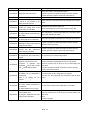
1.3.1
Communication model
"OSI reference model" is a famous communication mechanism model defined by ISO
(International Organization for Standardization).
This model classifies the functions required for communication into 7 layers.
Layer
7
6
5
4
3
2
1
Application layer
Functions
Image
"What the users wants to do"
• Agreement on contents of actual services
• What the users can see
• Available services themselves
Presentation layer
"Definition and conversion of data format"
• Definition of data representation system
• Coding/decoding and compression/decompression
of data
• Text code, data format
Session layer
"Communication connection establishment"
• Connection establishment/disconnection
• Authentication of connection
• Synchronization for transmitting data
Transport layer
"Delivering to the target correctly"
• Securing reliable data transfer between the
source and destination.
• Error correction (arrival sequence correction,
retransmission request)
• Flow control of communication
Network layer
"Communication procedure with the target not
adjoining”
• Definition of path control (routing)
• Definition of communication path decision
• Establishment of virtual connection using
address
Data link layer
"Data delivery to the next"
• Communication procedure between adjacent
devices.
• Format definition of transmission and reception
data
• Data error detection between devices and
correction method definition
Physical layer
"Physical connection"
• Conditions for electrical connection at the
lowest level
• ON/OFF definition of data signals
• Connector shape and pin layout for each signal
Protocol example
Protocol for each application
Remote login
TELNET protocol
File transfer
FTP protocol
Data
format
A
Network
common format
Data
format
B
Absorption of differences in data representation
HTTP
TELNET
FTP
SMTP
MIME
HTML
XML
Management of communication connection
RPC
Securing of reliability
TCP
UDP
ACK
IP
Selection of paths
0101
Conversion of frame and bit sequence
Data transfer between adjacent devices
0101
0101
Ethernet
PPP
Ethernet
ISDN
Telephone line
The bigger numbers correspond to the higher (more logical) layers and the smaller
numbers to the lower (more physical) layers.
IP corresponds to the network layer, and both TCP and UDP to the transport layer.
Ethernet corresponds to the data link layer and the physical layer.
1-6
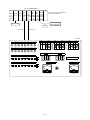
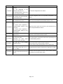
<Ethernet module and communication model>
The following shows the software configuration of the Ethernet module
corresponding to the "OSI reference model".
The Physical and Data link layers correspond to the "Ethernet" part of the Ethernet
module.
The Network and the Transport layers correspond to "IP" and "TCP/UDP" parts of
the Ethernet module.
Much higher layers such as Session, Presentation and Application correspond to
the software part for various functions designed specific to the MELSEC-Q, which
has been realized by combinations of the Q series PLC CPUs and the Ethernet
module.
Personal computer/work-station
OSI reference model
corresponding to the PLC
configuration
PLC
(Layers)
Q series PLC CPU
User program
CPU
Dedicated instruction
TCP
UDP
IP
ICMP
ARP
Etherrnet
(100BASE-TX,10BASE-T,10BASE5, 10BASE2)
Communication
by Web
FTP
Communication
by e-mails
Communication via
MELSECNET/H,
MELSECNET/10
Communication using
the MC protocol
Communication using
random access buffer
Communication using
fixed buffer
Socket
Communication using
data link instructions
Buffer memory
System call
SMTP
POP3
DNS
HTTP
TCP/UDP
IP
Etherrnet
(100BASE-TX,10BASE-T,10BASE5, 10BASE2)
1-7
ICMP
ARP
7
6
5
Application layer
Presentation layer
Session layer
4
Transport layer
3
Network layer
2
1
Data link layer
Physical layer
Ethernet
module
1.3.2
IP protocol
(1) Role of IP
IP is a network layer protocol which is processed by all devices connected to an IP
network.
The most important role of the TCP/IP (UDP/IP) network is "data transfer to a
device or PLC at the target address".
This role is achieved by IP (Internet Protocol).
Data (packets) are delivered with the information called "IP header" (tag) attached.
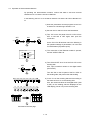
(2) Restrictions on IP
Although IP transfers data to a target PLC, there are some restrictions.
(a) No guarantee to reach the destination
3
2
IP network
1
3
1
2
1
(b) No guarantee to reach in the order of sending
3
2
IP network
1
3
(c) As the transfer size at one time is limited, a packet may be divided into
several pieces at transmission. (*1)
1
IP network
1-2
1-1
(d) No guarantee for no data damage
Damaged data
123456789
IP network
124789356
To put it shortly, IP bends every effort to transfer data (packets) to the target device or
PLC, however, it does not guarantee delivery of packets (Best effort).
Note that, there is no need to consider these restrictions when using TCP over IP.
When using UDP as a higher layer, care should be taken since the above restrictions
apply except the data damage detection.
*1 The size of one message (1 packet) that can be transmitted by the Ethernet
module is up to 1500 bytes (including the IP header).
Data exceeding 1500 bytes are divided in either case of the TCP/IP or UDP/IP
communication. The divided data are reassembled into one data on the receiving
side and handed to the application program.
1-8
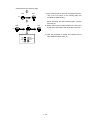
1.3.3
TCP and UDP
TCP and UDP are protocols which are processed by the devices and PCs on the both
ends of communication (Transport layer).
(1) Port Number
The actual communication is performed between the application programs
operated on devices and PCs.
TCP and UDP identify which application programs are communicating with each
other using the port number.
If the IP address is regarded as "address", the port number corresponds to “the
floor of a building".
3rd floor of building
(Port No.)
2nd floor of building (Port No.)
Application program A
IP network
Application program B
Application program D
Application program C
Application program E
Address XX (IP address)
Address YY (IP address)
In reality, combinations of the following five items identifiy individual
communication.
• Destination IP address
• Source IP address
• Destination port number
• Source port number
• Protocol number (TCP=6H, UDP=17H)
1-9
(2) Comparison between TCP and UDP
The request level for the network differs depending on the user application.
However, it is difficult to create each unique protocol for many requests.
Then, TCP (Transmission Control Protocol) and UDP (User Datagram Protocol)
are developed as minimally-required basic services.
TCP .............Fixes connection to the destination at first and performs bidirectional
1:1 communication with high reliability.
UDP.............Performs one-way communication to transfer the data given from an
application to the designated destination.
This is a high speed communication as data are directly sent using
IP.
The following table compares the characteristics of TCP and UDP.
Item
TCP
UDP
Reliability
High
Low
(Processing) Speed
Low
High
No. of target devices
1:1
1:1 or 1:n
Remarks
Unicast (1:1 communication)
Multicast (1:n communication)
(*1)
Guarantee to reach
Guaranteed
Not guaranteed
Operation when send
Resends automatically
No resending (packet
error occurs
(depending on setting)
disposal)
Required
Not required
destination
Communication
connection
establishment
Stream type (Instructions
Transfer type
and data are sent with
character strings)
Datagram type
(Sent in fixed format)
Reaches in order of sending
packets for TCP.
Datagram transfer can be
performed in the application level
even for TCP.
Sending side controls the send
Flow control
Available
Not available
data amount depending on the
buffer size of the receiving side.
Congestion control
(Resend control) (*2)
Send packet amount is controlled
Available
Not available
degree of the network.
Target device change
during an open
depending on the congestion
Not possible
Possible (*3)
connection
Refer to Section 2.3 for
connection.
TCP is suitable for assured data transfer.
UDP is suitable for real time monitoring by the PC display.
*1 The "n" of multicast (1:n communication) represents multiple devices
belonging to one group on the same Ethernet.
*2 The buildup of communication packets on the network is called "congestion".
*3 Target device change during an open connection may cause communication
troubles.
Do not change the target device while a connection is open.
1 - 10
1.4
1.4.1
MELSEC-Q Ethernet Module
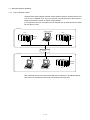
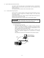
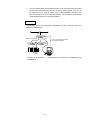
Role of Ethernet module
The Ethernet module supports the data communications between external devices and
a PLC CPU or between PLC CPUs on Ethernet, and sends/receives data to/from a
target device with the TCP/IP or UDP/IP communication.
In consequence, the PLC CPU status can be checked from an external device located
far from the PLC CPU.
Factory A
External device
PLC
PLC
Ethernet
module
Ethernet
module
Router
Factory B
Ethernet
module
External device
External device
PLC
All the external devices can communicate with PLCs in factories A and B via Ethernet.
Also, the PLCs in factories A and B can communicate with each other.
1 - 11
1.4.2
Outline of Ethernet module
(1) Supporting the TCP/IP and UDP/IP communications
The Ethernet module supports the TCP/IP and UDP/IP communications.
A communication method suitable for the target device can be selected.
(2) Data code selection is available
The Ethernet module can handle binary or ASCII code data.
For details of data codes, refer to Section 2.1.
(3) Three communication functions provided for various purposes
The Ethernet module has three communication functions shown below.
Data communication can be performed with either one of these functions,which is
selected according to the user's communication purpose.
For details, refer to Section 2.2.
• Communication using the MC protocol
• Communication using the fixed buffer (Procedure exist, No procedure)
• Communication using the random access buffer
POINT
The communication method and the data code for the data to be transfered should
match between the communicating devices.
(4) Remote communications by e-mail
The e-mail function enables data communication with a PLC in a remote place.
By setting an automatic notification condition, an e-mail is automatically sent when
the condition is satisfied.
(5) Internet access using the Web function (QJ71E71-100 only)
A system administrator can monitor a Q series PLC CPU in a remote place via the
Internet using a commercially-available Web browser.
For using the Web function, it is necessary to store the communication library,
user-created screens and Q series CPU access programs in the Web server.
1 - 12
CHAPTER 2
2.1
BEFORE USING ETHERNET MODULE
Two Data Codes
The Ethernet module can exchange data with external devices using binary or ASCII
codes.
The code setting can be switched between binary and ASCII using GX Developer.
For details, refer to Section 4.6.
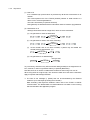
(1) Communication using the binary code
The Ethernet module sends/receives 1-byte data without change.
(a) Merit
1) The capacity of data to be sent/received is a half compared to the ASCII
code, and the load on the line is reduced.
2) The data of 00H to FFH can be processed.
(b) Demerit
To display numerical data, they must be converted to the ASCII code data.
Example: When sending/receiving 1234H
External device
12 H 34 H
Ethernet module
12 H 34 H
1-byte data are sent/received without change.
2-1
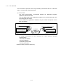
(2) Communication using the ASCII code
The Ethernet module sends/receives 1-byte data as data equivalent to two
characters in the ASCII code.
(a) Merit
On the external device side, data can be displayed as they are.
(b) Demerit
1) The capacity of data to be sent/received is doubled in size compared with
the data in the binary code, and the load on the line is increased.
2) Numerical data must be converted between ASCII and binary codes.
3) (On the Ether module side, data will be automatically converted.)
Example: When sending/receiving "1234"
Ethernet module
External device
"
1"
31H
"
2"
32H
"
3"
"
33H
4"
34H
12 H 34 H
ASCII code
Co
nv
er
sio
n
1-byte data on the PLC side are sent/received as data equivalent to two characters
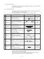
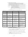
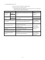
(3) Relationship between each communication method and data codes
The following shows the usability of data codes in each communication method.
Data communication function
Communication using MC
protocol
Automatically open UDP
port
Communication data code setting
Binary code
ASCII code
*1
-
*1
-
User open port
Communication using fixed With procedures
buffer
No procedure
Communication using random access buffer
: Selectable -: N/A
*1 The Ethernet module performs communication using binary code data
regardless of the communication data code setting by GX Developer.
2-2
2.2
Types of Data Communication Functions
The Ethernet module has three types of communication functions: "Communication
using MC protocol", "Communication using fixed buffer" and "Communication using
random access buffer".
The following describes the outline of each communication function.
2.2.1
Communication using MC protocol
The MC protocol is used for reading or writing device data and programs of a PLC
CPU from/to a personal computer via an Ethernet module or a Q series serial
communication module.
On the personal computer side, creating a program for data transfer with MC protocol
enables an easy access to the PLC CPU.
On the PLC CPU side, there is no need to create a communication program.
POINT
When performing data communication using the MC protocol, refer to the Q
Corresponding MELSEC Communication Protocol Reference Manual.
(1) MC protocol functions
(a) Reading/writing PLC CPU data
This function allows data reading from or writing to the PLC CPU device
memory of the station (local station) connected to the Ethernet network
system or another station on the MELSECNET/H, MELSECNET/10 as well
as the intelligent function module buffer memory.
By reading and writing data, the PLC CPU operation monitoring, data
analysis and production management can be performed on a personal
computer.
Also, production instructions can be executed from the personal computer.
Reading/Writing to
device memory/buffer
memory is available
Read
Personal computer
Write
PLC CPU
2-3
(b) Reading/writing file in PLC CPU
This function reads and writes files such as sequence program files or
parameter files that are stored in the PLC CPU.
By reading and writing these files, file management for QCPUs and
QnACPUs on other stations can be performed on a personal computer.
Also, execution programs for the PLC CPU can be changed (replaced) from
the personal computer.
Reading/Writing
to sequence programs/
parameters is available
Read
Personal computer
Write
PLC CPU
(c) Remote control of the PLC CPU
This function enables the remote RUN/STOP/PAUSE/latch clear/reset
operations.
Remote operations of the PLC CPU can be performed from the personal
computer using the PLC CPU remote control function.
(2) Utilizing the MX Component, MX Links
For the personal computer which runs one of the operation systems below,
communication programs can be created without considering details of MC
protocol (transmission/reception procedures) using MX Component or MX Links
(SW3D5F-CSKP-E or later).
(Supported basic operation systems)
• Microsoft Windows 95 Operating System
• Microsoft Windows 98 Operating System
• Microsoft Windows NT Workstation 4.0 Operating System
• Microsoft Windows Millennium Edition Operating System (*1)
• Microsoft Windows 2000 Professional Operating System (*1)
*1 Supported from MX Component Version 2 or later.
R
R
R
R
R
R
R
R
R
R
The assignment dealing with MX Component is given in Chapter 5 of this
textbook.
Appendix 2 describes the features of MX Component.
2-4
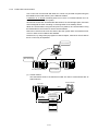
(3) External devices capable of exchanging data
The communication using the MC protocol can be performed from the following
external devices.
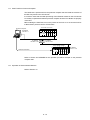
1) External devices that are connected to the same Ethernet as the Ethernet
module
2) External devices that are connected to other Ethernet networks via routers
3) External devices that are connected to the MELSECNET/H via PLC CPUs
2) Personal computer
Ethernet-2
1)
Router
Personal computer
Ethernet-1
PLC CPU
(Access
target station)
PLC CPU
MELSECNET/H
3) Personal computer
Personal computer
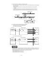
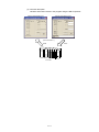
(4) Outline of data sending/receiving procedures
Data are sent/received as shown below.
(a) TCP/IP communication
PLC CPU
External device
Ethernet module
Receiving command
Device
memory
Sending ACK
Send
processing
Sending response
Receiving ACK
Receive
processing
(b) UDP/IP communication
PLC CPU
External device
Ethernet module
Receiving command
Send
processing
Sending response
Receive
processing
Device
memory
REMARK
Refer to the Q Corresponding Ethernet Interface Module User's Manual (Basic) for a
communication program example on the personal computer side when using the
following languages for communication using the MC protocol.
• Microsoft Corporation Visual C++
• Microsoft Corporation visual basic
R
R
2-5
2.2.2
Fixed buffer communication
A PLC CPU can communicate with other PLC CPUs or a personal computer using the
fixed buffers in the buffer memory of the Ethernet module
A maximum of 1k words of arbitrary data can be sent or received between PLCs or
between the PLC and the host system.
An Ethernet module has 16 fixed buffer data areas of 1k word storage space, and each
area is assigned as either a sending or receiving buffer for an arbitrary device.
While the communication using the MC protocol is passive, the communication using
the fixed buffers is the function for active communications.
Data can be sent from the PLC CPU side to the host system when a mechanical error
occurs or when some conditions are satisfied.
Furthermore, by using interrupt programs in data reception, retrieval of receive data to
the PLC CPU may be expedited.
Error confirmed!
Personal computer
Error occurred!
PLC CPU (Local station)
Error confirmed!
PLC CPU
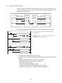
(1) Control method
The fixed buffer areas in the Ethernet module are used to communicate with an
external device.
External device
PLC CPU
Send
Receive
Buffer memory
BUFSND
instruction
Fixed buffer
BUFRCV
instruction
No.1
No.2
No.3
No.4
to
No.16
2-6
As shown in the diagram below, set IP addresses and usage conditions (e.g.
sending/receiving, with/without procedures) of external devices to respective fixed
buffer areas(No.1 to 16) when opening a connection (logic circuit) of the Ethernet
module to fix each external device to each buffer. (*1)
*1 The connection No. (1 to 16) used for data communication are the same as
those for the fixed buffer.
Fixed buffer No.1
For sending to external device 1
External device 1
Fixed buffer No.2
For receiving from external device 1
Fixed buffer No.3
For receiving from external device 8
External device 8
For sending to external device 28
Fixed buffer No.16
External device 28
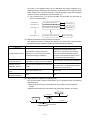
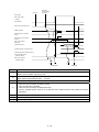
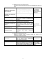
(2) Differences between with and without procedures
The following shows the differences between the fixed buffer communication
(Procedure exist) and the fixed buffer communication (No procedure).
Procedure exist
No procedure
The application programs of the local
Communication method
The application programs of the local
station’s PLC CPU and an external device
station’s PLC CPU and an external device
communicate without handshaking (Data
communicate through handshaking.
reception of data at external devices cannot
be confirmed for data transmission.)
Applications for
Communications using fixed buffer, random
connection opened
access buffer, and MC protocol are available.
Message format of
Message format determined by the Ethernet
application data unit
module
Communication data
code
Unit of data length for
dedicated instructions
Only fixed buffer communication is available.
No restrictions on the message format
(Communication is available in the message
format of the external device.)
ASCII code or Binary code
Binary code
Word
Byte
(3) External devices capable of exchanging data
The communication using the fixed buffer can be performed with the following
external devices.
1) External devices that are connected to the same Ethernet as the Ethernet
module
2) External devices that are connected to other Ethernet networks via routers
2) Personal computer
Ethernet-2
Router
1) Personal computer
Ethernet-1
PLC CPU
2-7
(Access station)
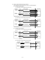
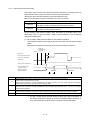
(4) Outline of data sending/receiving procedures
Data sending/receiving is performed as shown in the following figure.
(a) At TCP/IC communication
1) Fixed buffer communication (Procedure exist)
PLC CPU
BUFSND
instruction
Ethernet module
Send
request
Fixed buffer-n
External device
Data sending
ACK receiving
Response receiving
Completion
Receive
completion
BUFRCV
instruction
ACK sending
Receive
processing
Data receiving
Fixed buffer-m
Receive
completion
confirmation
ACK sending
Response sending
ACK receiving
Send
processing
2) Fixed buffer communication (No procedure)
PLC CPU
BUFSND
instruction
Ethernet module
Send
request
Data sending
Fixed buffer-n
ACK receiving
External device
Receive
processing
Completion
BUFRCV
instruction
Receive
completion
Data receiving
Fixed buffer-m
ACK sending
Receive
completion
confirmation
Send
processing
(b) At UDP/IP communication
1) Fixed buffer communication (Procedure exist)
PLC CPU
BUFSND
instruction
External device
Ethernet module
Send
request
Data sending
Fixed buffer-n
Response receiving
Receive
processing
Completion
BUFRCV
instruction
Receive
completion
Data receiving
Fixed buffer-m
Response sending
Send
processing
Receive
completion
confirmation
2) Fixed buffer communication (No procedure)
PLC CPU
BUFSND
instruction
BUFRCV
instruction
Sending
request
External device
Ethernet module
Fixed buffer-n
Data sending
Receive
processing
Data receiving
Send
processing
Completion
Receive
completion
Receive
completion
confirmation
2-8
Fixed buffer-m
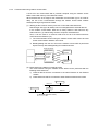
2.2.3
Communication using random access buffer
A PLC CPU can communicate with a personal computer using the random access
buffer in the buffer memory of the Ethernet module.
When the data size is too large for the fixed buffer communication (up to 1k words of
data), the use of the communication through the random access buffer enables
sending/receiving a large amount of data.
(1) Utilizing as the common memory for the PLC CPU and external devices
Data of larger size (up to 6k words) can be exchanged with the external devices.
In the random access buffer, data can be freely written to and read from any
external device (*1) without fixing access to a specific external device.
Thus, it can be used as a common buffer area for all of the external devices
connected to the Ethernet. (*2)
*1 The communication function using the random access buffer cannot be used
for the communication between PLC CPUs.
*2 Reading/writing from the PLC CPU to the random access buffer is performed
asynchronously with reading/writing from external devices.
Ethernet module
Buffer memory
Write
Random
access
buffer
Read
TO instruction
PLC CPU
FROM instruction
External
device
Write
Read
External
device
(2) External devices capable of exchanging data
The communication using the random access buffer can be performed with the
following external devices.
1) External devices that are connected to the same Ethernet as the Ethernet
module
2) External devices that are connected to other Ethernet networks via routers
2) Personal computer
Ethernet-2
Router
1) Personal computer
Ethernet-1
PLC CPU
(Access station)
2-9
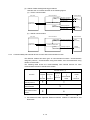
(3) Outline of data sending/receiving procedures
Data are sent or received as shown in the following figures.
(a) TCP/IC communication
External device
Ethernet module
PLC CPU
(When writing)
(Data)
Receiving command
(Read/write request)
Send
processing
Sending ACK
TO instruction
FROM instruction
Random access buffer
(Data)
(When reading)
Sending response
Receive
processing
Receiving ACK
(b) UDP/IP communication
(When writing)
(Data)
TO instruction
FROM instruction
Receiving command
(Read/write request)
Send
processing
Random access buffer
(Data)
(When reading)
2.2.4
External device
Ethernet module
PLC CPU
Sending response
Receive
processing
Communicability with external devices for each data communication function
The Ethernet module has three types of communication functions: "Communication
using MC protocol", "Communication using fixed buffer" and "Communication using
random access buffer".
The following table shows the communicability with external devices for each
communication function of the Ethernet module.
External device (*1)
Function
Personal
Personal
computer
computer
QJ71E71
QJ71E71
QJ71E71
QJ71E71
QJ71E71
Conventional
model
Conventional
model
QJ71E71
Communication using
the MC protocol
Communication using
the fixed buffer
Communication using
the random access
buffer
: Available
:N/A
*1 Conventional models represent Ethernet interface modules of MELSEC-A and
QnA series.
2 - 10
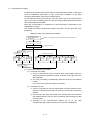
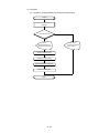
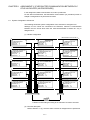
2.3
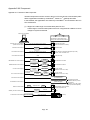
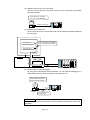
Open/Close Processing
For data communication with external devices using the Ethernet module, a connection
must be established (connection of logic circuit) after completion of the initial
processing automatically carried out at module start up.
For the Ethernet modules, there are two connection types: one for the system and the
other for the user. Completing all of the open processing makes data communication
with external devices executable.
When the communication is completed, the close processing is performed for the
established connection.
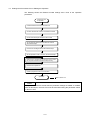
The following describes the Ethernet module connection, and its open and close
processing.
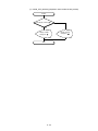
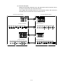
(Diagram of data communication procedures)
Set parameters for the
Ethernet module through
GX Developer
Refer to "4.3 Settings and Procedures Prior to Starting the Operation"
Start up the PLC CPU
Initial processing
Open processing
Refer to (2)
(Connection for
user No.1 to 16)
Communication
using the MC
protocol
Automatically started
(Connection for system)
Communication
using fixed
buffer
Communication
using random
access buffer
Close processing
Communication
using the MC
protocol
E-mail
sending/
receiving
MELSECNET/H,
MELSECNET/10
relay communication
Communication
using data link
instructions
File transfer
(FTP)
Communication Communication
using GX
using Web
Developer
function
Refer to (3)
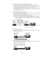
(1) Connection of the Ethernet module
(a) Connection for system
1) This is a connection for users to perform data communication using the
special functions of the Ethernet module, as shown on the right side of the
above diagram.
2) The open processing is automatically performed at start of the Ethernet
module.
Users need not to open and close the connection.
(b) Connection for user
1) This is a connection for users to perform data connection using the basic
functions of the Ethernet module, as shown on the left side of the above
diagram.
2) User performs the open processing when starting data communication
with external devices and the close processing when finishing the data
communication.
3) According to the communication method set up for the data
communication with external devices, the connection is established.
2 - 11
(In TCP/IP communication)
• The connection is established when the open processing is completed
normally.
• When the close processing performed after completion of the data
communication is normally completed, the connection is disconnected.
• There are the following methods for establishing a connection: Active
open and Passive open.
(Active open)
Active open makes a request to establish a connection to the
designated external device that is waiting for connection
establishment.
Compared to the telephone line, it is a caller side.
(Passive open)
There are Fullpassive open and Unpassive open.
Compared to the telephone line, it is a receiver side.
The open and close processing by Passive open on the Ethernet
module side can be performed from PLC CPU or the Ethernet module
system. (*1)
(Fullpassive open)
Fullpassive open waits for a connection establishment request (Active
open) addressed to the local station from the designated external
device.
(Unpassive open)
Unpassive open waits for a connection establishment request (Active
open) addressed to the local station from any external devices.
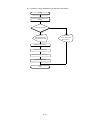
(Diagram of connection establishing procedure)
PLC CPU
Initial processing
Initial completion
Ethernet module
Initial request
Initial request
Initial completion
Fullpassive/
Unpassive
open
Ethernet module
PLC CPU
Initial processing
Initial completion
Initial completion
Open
Active open
Waiting for
open request
Open request
Open completion
Open completion
Open completion
Open completion
(In UDP/IP communication)
• The open and close processing is done as internal processing of the
Ethernet module to enable data communication with external devices.
• A connection is established during data communication after the open
processing is completed normally.
• The open and close processing on the Ethernet module side in the
UDP/IP communication can be performed from the PLC CPU or the
Ethernet module system. (*1)
2 - 12
*1 For the open and close processing on the Ethernet module side shown
below, there are two methods:performing from the PLC CPU and by the
Ethernet module system. The method is determined by the following
parameter setting value for the Ethernet module on the GX Developer.
• The open and close processing by Passive open in the TCP/IP
communication
• The open and close processing in the UDP/IP communication
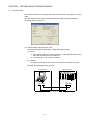
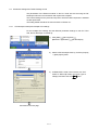
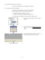
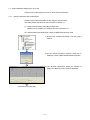
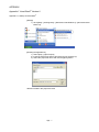
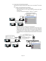
(1) If the following 1) and 2) are satisfied in the parameter settings for the
Ethernet module on GX Developer, the Ethernet module system
performs the open and close processings of the corresponding
connection.
No open and close processing from sequence programs is required.
(Refer to the next page for the setting screen.)
1) "Always wait for OPEN" is set for "Initial timing" of the operational
settings. (Common setting to all connections for users)
2) For the connection for users, the following are set for "Protocol"
and "Open system" of the open setting.
• "Protocol" = TCP, "Open system" = Unpassive
• "Protocol" = TCP, "Open system" = Fullpassive
• "Protocol" = UDP, "Open system" = (No setting is required)
REMARK
When the Ethernet module was started in the setting described above
(Connection set as "Protocol" = TCP)
• The open processing (Active open) from an external device makes
the connection open and enables data communication.
• For finishing the data communication, the close processing from the
external device disconnects the connection.
• If necessary, perform the open and close processing from external
devices, and executes data communication at any time.
However, when closing a connection from the PLC CPU side due to
a communication error while the connection is open, use the
CLOSE instruction in the sequence program.
In this case, as the wait for OPEN processing of the corresponding
connection will not be performed by the Ethernet module system, all
the subsequent open processing (using the OPEN instruction) and
close processing on the Ethernet module side must be performed
using the sequence program .
("Protocol" = UDP)
Starting the Ethernet module enables the data communication with
external devices.
2 - 13
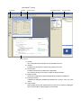
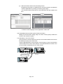
(2) If the following 1) or 2) are set in the previously mentioned parameter
settings, the open and close processing of the corresponding
connection is performed using the sequence program.
The Ethernet module system does not perform the open and close
processing.
1) "Do not wait for OPEN" is set for "Initial timing" in the operational
settings. (Common setting to all connections for users)
2) For the connection for users, the following are set for "Protocol"
and "Open system" of the open setting.
• "Protocol" = TCP, "Open system" = Active
2 - 14
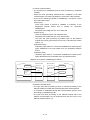
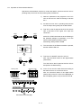
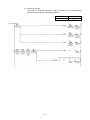
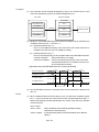
(2) Open processing
(a) The open processing is a processing which enables data communication with
external devices.
1) In TCP/IP communication
• The Ethernet module system communicates with an external device
using a connection after establishing the connection (connection of logic
circuit).
• The users can send and receive data using the connection after
completing the open processing normally.
2) In UDP/IP communication
• The Ethernet module system performs the internal processing.
• The users can send and receive data through the open connection after
completing the open processing normally.
(b) In order to perform the open processing, the initial processing must have
been completed normally.
(c) Connections can be opened for up to 16 external devices.
Note that two fixed buffers are required when communicating with the same
external device using the fixed buffer communication. Because of this, the
number of the external devices may be reduced.
POINT
Note the following when performing the communications using the MC protocol
and the random access buffer.
• To continue data communication even after turning the PLC CPU of the
Ethernet-module-installed station to STOP, set "Initial timing" to "Always wait for
OPEN (Communication possible at STOP time)".
2 - 15
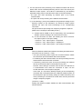
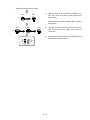
(3) Close processing
(a) The close processing is a processing which disables data communication
with external devices.
1) In TCP/IP communication
• The Ethernet module system communicates with the external device
using the connection used in data communication and disconnects the
connection (disconnection of logic circuit).
• Completing the close processing normally enables change of the
external device that uses the connection.
2) In UDP/IP communication
• The Ethernet module system performs the internal processing.
• Completing the close processing normally enables change of the
external device that uses the connection.
(b) The close processing is performed mainly in the following cases.
• Terminate a connection with an external device
• Change an external device to communicate
• Change communication conditions
(c) Perform the close processing using the sequence program for the connection
that has been opened using the sequence program.
(d) Determine the timing for the close processing with the external device.
POINT
Even if the close processing is not requested, the open completion signal
(corresponding bit in address: 5000H) automatically turns off and the
communication line is closed in the following cases:
(1) When an existence confirmation function time out occurs.
(2) When a close or ABORT (RST) instruction is received from an external device.
(3) When the Active open request is received again from the external device in the
open completion status of TCP/IP. (The connection will be closed after the RST
command is sent.)
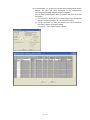
2 - 16
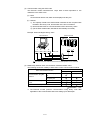
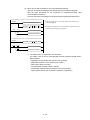
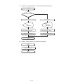
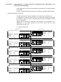
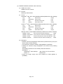
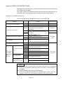
2.3.1
Active open/close processing
The Active open executes the connection processing to the external device, which
TCP/IP connection is in the wait for OPEN status (Fullpassive/Unpassive), and
enables data communication.
Ethernet module
PLC CPU
Initial processing
Ethernet module
Initial request
Initial completion
Initial request
Initial completion
Fullpassive/
Unpassive
open
PLC CPU
Initial processing
Initial completion
Initial completion
Open
Active open
Waiting for
open request
Open request
Open completion
Open completion
Open completion
Open completion
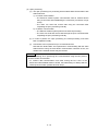
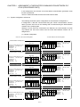
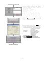
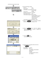
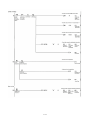
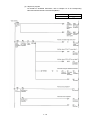
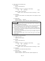
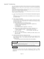
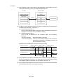
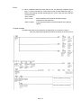
The following describes an Ethernet module sequence program and a timing chart.
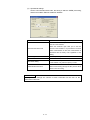
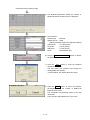
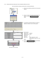
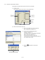
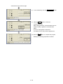
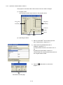
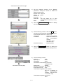
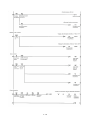
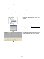
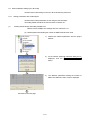
<<Open processing for connection No.1 using the dedicated OPEN instruction>>
When using "Application" set in "Open settings" of GX Developer (*1)
direction
Control data [D0]: H0
Set the control data to D0 to D8
ZP.OPEN
M0
"U0" K1
D0
M0
When setting "Application" in "Control data" of OPEN instruction (*1)
[D0]: H8000
Set [D1] to [D9] according to the application
M1
Processing for normal completion
M1
Processing for error completion
<<Close processing for connection No.1 using the dedicated CLOSE instruction>>
direction
ZP.CLOSE " U0" K1 D100 M100
M100
M101
Processing for normal completion
M101
Processing for error completion
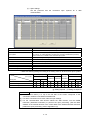
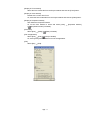
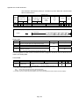
*1 The setting items of "Application" are as follows.
For details, refer to the Q Corresponding Ethernet Interface Module User's Manual
(Basic).
• Application of fixed buffers (For sending, For receiving)
• Destination existence check (Confirm, No confirm)
• Paring open (Pairs, No pairs)
• Communication method (TCP/IP, UDP/IP)
• Fixed buffer communication (Procedure exist, No procedure)
• Open system (Active open or UDP/IP, Unpassive, Fullpassive)
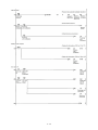
2 - 17
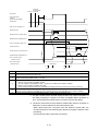
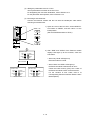
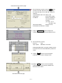
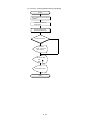
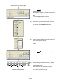
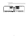
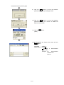
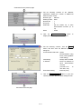
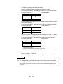
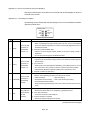
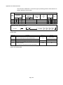
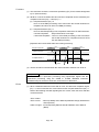
Power-on
Parameter
communication
completed
Open status
1)
Open ready status
(closed)
Closed status
Initial normal completion X19
2)
OPEN instruction
One scan
OPEN instruction complete
device
OPEN instruction complete
device +1
Open error detection
signal X18
5)
CLOSE instruction
One scan
CLOSE instruction complete device
CLOSE instruction complete device +1
Open completion signal
(Address: 5000H)
Open request signal
(Address: 5002H)
SYN
3)
FIN
4)
SYN+ACK
Number
1)
2)
3)
6)
7)
FIN+ACK
Description
After parameter communication, confirm normal completion of the Ethernet module initial processing.
(Initial normal completion signal (X19): ON)
Start the open processing using the dedicated instruction, OPEN.
(Open request signal (address: 5002H … b0): ON)
The open processing is executed.
• When the open processing completes normally
Data communication is enabled.
4)
• When the open processing completes abnormally
Confirm "Complete status" stored in the control data of the OPEN instruction and perform the recovery
processing.
5)
Start the close processing using the dedicated instruction-CLOSE instruction. (Open request signal: OFF)
6)
The close processing is executed.
7)
Open completion signal turns OFF.
2 - 18
2.3.2
Passive open/close processing
The Passive open puts the open request (connection request by Active open) from an
external device of the TCP/IP connection into the receive wait status.
The Passive open includes Unpassive open and Fullpassive open.
Both of them are passive open processings for the TCP connection.
Open system
Description
Unpassive
Waits for receiving an open request (connection request) addressed to the
local station from any of all the devices connected to a network.
Fullpassive
Waits for receiving an open request (connection request) addressed to the
local station from the designated devices.
The processing of the Ethernet module varies depending on the setting value of the
initial timing ("Do not wait for OPEN", "Always wait for OPEN") in the operational
settings of GX Developer.
(1) When setting "Always wait for OPEN" in the operational settings
The Ethernet module system always puts the connection into the wait-for-OPEN
status.
(No sequence programs for the open and close processing are required.)
Parameter
communication
completed
1)
Power-on
Open status
(*1)
Open ready status (closed)
(Active open acceptable)
Close status
Initial normal completion X19
4)
Open completion signal
(Address: 5000H)
Open request signal
(Address: 5002H)
2)
SYN
Number
1)
2)
3)
4)
FIN+ACK
SYN+ACK
3)
FIN
Description
After parameter communication, confirm normal completion of the Ethernet module initial processing.
(Initial normal completion signal (X19): ON)
After the initial processing is normally completed, the connection is placed in the open ready status and the Ethernet
module waits for receiving an open request from an external device.
The Ethernet module starts the open processing upon receiving the open request (SYN) from the external device.
When the open processing is normally completed, the open completion signal (address: 5000H… b0) turns on and data
communication is enabled.
The Ethernet module starts the close processing upon receiving the close request (FIN) from the external device.
When the close processing is completed, the open completion signal turns off and the data communication is disabled.
After the Ethernet module’s close processing is completed, the connection returns to the open ready status.
*1 An open request (SYN) received during the time from normal completion of
the initial processing to change to the open acceptable status generates an
error, and the Ethernet module sends a connection forced close (RST).
2 - 19
(2) When "Do not wait for OPEN" is set in the operational settings
The open and close processings are performed using the sequence program.
After the open processing for the connection is completed normally, data
communication is enabled.
The open and close processing must be performed using dedicated instructions.
<<Open processing for connection No.1 using the dedicated OPEN instruction>>
When using "Application" set in the "Open settings" of GX Developer (*1)
Control data [D0]: H0
direction
Set the control data to D0 to D9
ZP.OPEN
M0
"U0" K1
D0
M0
M1
When setting the "Application" in the "Control data" of OPEN instruction (*1)
[D0]: H8000
Set [D1] to [D9] according to the application
Processing for normal completion
M1
Processing for error completion
<<Close processing for connection No.1 using the dedicated CLOSE instruction>>
direction
ZP.CLOSE " U0" K1 D100 M100
M100
M101
Processing for normal completion
M101
Processing for error completion
*1 The setting items of "Application" are as follows.
For details, refer to the Q Corresponding Ethernet Interface Module User's
Manual (Basic).
• Application of fixed buffers (For sending, For receiving)
• Destination existence check (Confirm, No confirm)
• Paring open (Pairs, No pairs)
• Communication method (TCP/IP, UDP/IP)
• Fixed buffer communication (Procedure exist, No procedure)
• Open system (Active open or UDP/IP, Unpassive, Fullpassive)
2 - 20
Parameter
communication
Power-on completed
Open status
1)
(*1)
Open ready status
(closed)
(Active open acceptable)
Closed status
Initial normal completion X19
2)
OPEN instruction
One scan
OPEN instruction complete device
OPEN instruction complete device +1
Open error detection signal X18
5)
CLOSE instruction
One scan
CLOSE instruction complete device
CLOSE instruction complete device +1
Open completion signal
(Address: 5000H)
Open request signal
(Address: 5002H)
SYN+ACK
3)
SYN
Number
1)
2)
3)
4)
5)
FIN+ACK
(*2)
4)
FIN
Description
After the parameter communication, confirm normal completion of the Ethernet module initial processing.
(Initial normal completion signal (X19): ON)
Start the open processing using the dedicated instruction, OPEN.
(Open request signal (address: 5002H … b0): ON)
The Ethernet module starts the open processing upon receiving the open request (SYN) from the external device.
• When the open processing completes normally
The open completion signal (address: 5000H… b0) turns on and data communication is enabled.
• When the open processing completes abnormally
Confirm "Complete status" stored in the control data of the OPEN instruction and perform the recovery processing.
The Ethernet module starts the close processing upon receiving the close request (FIN) from the external device.
When the close processing is completed, the open completion signal turns off and the data communication is disabled.
Start the close processing using the dedicated instruction, CLOSE. (Open request signal: OFF)
*1 An open request (SYN) received during the time from normal completion of
the initial processing to change to the open acceptable status generates an
error, and the Ethernet module sends a connection forced close (RST).
*2 The above chart shows how the Ethernet module side closes a connection in
response to a close request from the external device side.
When disconnecting the connection from the Ethernet module side, the
CLOSE instruction is executed using the sequence program to start the close
processing.
(The FIN is sent and the FIN+ACK is received.)
2 - 21
2.3.3
UDP/IP open/close processing
The open and close processing in UDP/IP is internal processing of the Ethernet
module.
The processing of the Ethernet module varies depending on the setting value of the
initial timing setting ("Do not wait for OPEN", "Always wait for OPEN") in the
operational settings of GX Developer.
(1) When "Always wait for OPEN" is set in the operational settings
The Ethernet module system is put into the status where data communication can
be always performed.
(No sequence program for the open and close processing is required.)
REMARK
When the open or close processing has been done using the dedicated instructions OPEN or CLOSE from the Ethernet module side, all the open or close processing of
the corresponding connection after that should be performed by the sequence
program even if "Always wait for OPEN (Connection possible at STOP time)" is set.
(The open and close processing same as that for "Always wait for OPEN
(Communication impossible at STOP time)" is required.)
(2) When "Do not wait for OPEN" is set in the operational settings (Communications
impossible at STOP time)
The open and close processing is performed using the sequence program.
After the open process of the connection is completed normally, data
communication is enabled.
The open and close processing must be performed using the dedicated
instructions.
<<Open processing for connection No.1 using the dedicated OPEN instruction>>
When using "Application" set in "Control data" of GX Developer (*1)
Control data [D0]: H0
direction
Set the control data to D0 to D9
ZP.OPEN
M0
"U0" K1
D0
M0
M1
When setting the "Application" in "Control data" of OPEN instruction (*1)
[D0]: H8000
Set [D1] to [D9] according to the application.
Processing for normal completion
M1
Processing for error completion
<<Close processing for connection No.1 using the dedicated CLOSE instruction>>
direction
ZP.CLOSE " U0" K1 D100 M100
M100
M101
Processing for normal completion
M101
Processing for error completion
*1 Refer to Section 2.3.1 for the setting items of "Application".
For details, refer to the Q Corresponding Ethernet Interface Module User's
Manual (Basic).
2 - 22
Power-on
Parameter
communication
completed
Open status
Open ready status
(closed)
1)
Closed status
Initial normal completion X19
2)
OPEN instruction
One scan
OPEN instruction complete device
OPEN instruction complete device + 1
5)
CLOSE instruction
One scan
CLOSE instruction complete device
CLOSE instruction complete device + 1
7)
Open completion signal
(Address: 5000H)
3)
Number
1)
2)
3)
4)
5)
6)
7)
Internal
processing
4)
6)
Internal
processing
Description
After parameter communication, confirm normal completion of the Ethernet module initial processing.
(Initial normal completion signal (X19): ON)
Start the open processing using the dedicated instruction, OPEN.
(Open request signal (address: 5002H … b0): ON)
The Ethernet module executes the open processing. (Internal processing only)
• When the open processing completes normally
Open completion signal (address: 5000H ... b0) turns on. Data communication is enabled.
• When the open processing completes abnormally
Confirm "Complete status" stored in the control data of the OPEN instruction and perform the recovery processing.
Start the close processing using the dedicated instruction, CLOSE. (Open request signal: OFF)
The close processing is executed. (Internal processing only)
Open completion signal turns OFF.
2 - 23
MEMO
2 - 24
CHAPTER 3
3.1
SYSTEM CONFIGURATION
Applicable Systems
The Ethernet modules can be used in systems to which the following descriptions
apply.
(1) Applicable modules and number of mountable modules
The following table lists the CPU modules and remote I/O stations where the
Ethernet module can be mounted and the number of mountable modules.
Applicable Module
*1
*2
*3
Remark
Q02CPU
Q02HCPU
Q06HCPU
Q12HCPU
Q25HCPU
Up to 4
• Available only in Q mode.
• Up to 8 in total including
modules for MELSECNET/H
(*1)
Q00JCPU
Q00CPU
Q01CPU
1 at max
(*1)
QJ72LP25-25
QJ72LP25G
QJ72BR15
Up to 4
MELSECNET/H remote I/O
station
(*2)(*3)
CPU module
Remote I/O station
Number of modules that can
be mounted
Refer to the User's Manual (Function Explanation, Program Fundamentals)
for the CPU module to be used.
Refer to the Q Corresponding MELSECNET/H Network System Reference
Manual (Remote I/O network).
Use the Ethernet module of function version B.
(2) Applicable base unit
The Ethernet module can be mounted in any I/O slot (*1) of the base unit.
*1 Limited within the I/O point range of the CPU module and remote I/O station.
(3) Applicable software packages
The following table shows the software packages available for the Ethernet
module.
(a) Software for PLC
Product name
GX Developer
Model
Remark
SWnD5C-GPPW-E
MELSEC PLC programming software.
The "n" in the model name must be 4 or
greater.
(b) Communication support tool for external devices
Product name
Model
Remark
MX Component
SWnD5C-ACT-E
Active X library for communication.
The "n" in the model name must be 0 or
greater.
MX Links
SWnD5F-CSKP-E
DLL library for communication.
The "n" in the model name must be 3 or
greater.
3-1
3.2 Devices Required for Network Configuration
This section explains the devices that are required to configure a network.
Network installation work needs sufficient safety measures; please ask a qualified
network installer.
REMARK
This section is described for use of QJ71E71-100.
For the other modules (QJ71E71, QJ71E71-B2), refer to Q corresponding Ethernet
Interface Module User's Manual (Basic).
(1) When configuring an Ethernet system using QJ71E71-100
When connecting the QJ71E71-100 to a network, either 10BASE-T or
100BASE-TX can be used.
The Ethernet module detects whether it is 10BASE-T or 100BASE-TX according
to the hub.
(a) Connection using 100BASE-TX
Hub
Twisted pair cable
* Up to 2 stages are allowed
for cascade connection
External device
Ethernet
module
Use the devices that satisfy the standards of IEEE802.3 ,100BASE-TX.
(About the devices shown under the hub)
• Shielded twisted pair cable (STP cable) (category 5)
* Straight cables can be used.
(Correct operation is not guaranteed if a crossed cable is connected to an
external device via 100BASE-TX of the Ethernet module.
However, use of crossed cables is allowed for data communication
between two Ethernet modules (i.e., two QJ71E71-100 modules) or for
connection to a GOT.)
• RJ45 jacks
• 100Mbps hub
3-2
(b) Connection using 10BASE-T
Hub
Twisted pair cable
* Up to 4 stages are allowed
for cascade connection
External device
Ethernet
module
Use devices that satisfy the standards of IEEE802.3, 10BASE-T.
(About the devices shown under the hub)
• Unshielded twisted pair cable (UTP cable) (category 3 (4, 5))
* Straight cables can be used.
(Correct operation is not guaranteed if a crossed cable is connected to an
external device via 10BASE-T of the Ethernet module.
However, use of crossed cables is allowed for data communication
between two Ethernet modules (i.e., two QJ71E71-100 modules, or
QJ71E71 and QJ71E71-100) or for connection to a GOT.)
• RJ45 jacks
• 10Mbps hub
POINT
In the high-speed communication (100Mbps) by 100BASE-TX connection, a
communication error may occur due to the effect of high frequency noise from
devices other than the PLC in a given installation environment.
The following describes preventive measures on the QJ71E71-100 side, which can
be taken for the construction of a network system.
(1) Wiring
• Do not connect the twisted pair cables together with the main circuit and the
power wires.
• Make sure to place the twisted pair cables in a duct.
(2) Communication method
• Use the TCP/IP communication.
• Increase the number of retries as necessary.
(3) 10Mbps communication
• Replace the hub connected to the QJ71E71-100 with the one capable of
handling 10Mbps to perform communications at the data transmission rate of
10Mbps.
3-3
MEMO
3-4
CHAPTER 4
4.1
SPECIFICATIONS OF ETHERNET MODULE & SETTINGS AND
PROCEDURES PRIOR TO OPERATION
Performance Specifications
The following explains the performance specifications of the QE71E71-100.
For the performance specifications of other Ethernet modules, refer to Q
corresponding Ethernet Interface Module User's Manual (Basic).
Specifications
Item
100BASE-TX
Data transmission speed
10BASE-T
100Mbps
Transmission method
10Mbps
Base band
Maximum node-to-node
distance
Transmission
specifications
Length between hub and
node
Maximum No. of
nodes/connection
100m
Cascade connection Maximum 2 stages
Cascade connection Maximum 4 stages
Interval between the
minimum nodes
Transmission
data storage
memory
Number of simultaneously
open connection allowed
16 connections (Connections usable by the sequence program)
Fixed buffer
1k words
Random access buffer
6k words
E-mail
Attached file
Main text
Number of I/O points occupied
1 (*1)
960 words
1 (*1)
0.50A
Depends on the specifications of the power module to which the Ethernet module is
installed.
Withstand voltage
Insulation resistance
External dimensions
98 (H) x 27.4 (W) x 90 (D) [mm]
Weight
0.11kg
Data
size
Attached file
Main text
Data transfer method
Subject
6k words
MIME
Data format of attached
file
Division of attached file
When sending (encode)
When receiving (decode)
Encryption
Compression
Communication with mail
server
1
960 words 1
When sending: Sends either a file as attachment or main text (select one).
When receiving: Receives a file as attachment.
Us-ASCII format or ISO-2022-JP (Base64)
Attached file format
E-mail
transmission
specifications
Transmission
and reception
data
(*1)
1
6k words
32 points (I/O assignment: intelligent)
5V DC internal current consumption
Noise durability
16
MIME format
Version 1.0
Binary/ASCII/CSV can be selected.
File name: XXXX.bin(binary), XXXX.asc(ASCII), XXXX.csv(CSV)
(CSV: Comma Separated Value)
Cannot be divided (only one file can be sent/received)
* If any divided file is received, only the first file will be received and the remaining files will
be discarded.
Subject
: Base64/7bits
Main text
: 7bits
Attached file : Base64
Subject
: (Does not decode)
Main text
: (Cannot be received)
Attached file : Base64/7bit/8bit/Quoted Printable
* If e-mail is sent from the external device to the PLC side, specify the encoding method
(Base64/7 bits/8 bits/Quoted Printable) of the attached file.
No
No
SMTP (sending server) Port number=25
POP3 (receiving server) Port number=110
4-1
*1
The e-mail transmission and reception function of the PLC CPU and the random
access buffer communication function cannot be used together. Only one of
the functions can be used at a time. (The e-mail transmitting function of the
Ethernet module's PLC CPU monitoring function and the random access buffer
communication function can be used together.)
REMARK
The following shows the transmission specification for the connection using the
10BASE-T/100BASE-TX.
Hub
Maximum 100m (5m)
Maximum
100m
Up to 4 (2) stages are allowed
for cascade connection
Ethernet
module
* The item in parentheses ( ) indicates when a connection is established using
100BASE-TX.
4-2
4.2
Ethernet Module Function List
This section shows a list of Ethernet module functions.
(1) Basic functions of the Ethernet module
The Ethernet module can perform the communications shown in the table below
using the TCP/IP or UDP/IP communication.
Function
Communication
using the MC
protocol
Communication
QnA compatible
3E frame
Reads/writes PLC CPU data from/to an external
A compatible 1E
device.
Procedure exist
Reference section
MELSEC
Communication Protocol
Reference
frame
using the fixed
buffer
Description
Sends/receives arbitrary data between the PLC CPU
Chapter 6
and the external device using the fixed buffer of the
No procedure
Chapter 7
Ethernet module.
Q Corresponding
Communication using the random
Reads/writes data from multiple external devices to the
Ethernet Interface
access buffer
random access buffer of the Ethernet module.
Module User's Manual
(Basic)
Sends/receives data by e-mail.
Sending/receiving by e-mail
• Sending/receiving by PLC CPU
• Sending by PLC CPU monitoring function (automatic
notification function)
Q Corresponding
Ethernet Interface
Communication using data link
Reads/writes the PLC CPU data of other station via
Module User's Manual
instructions
Ethernet using data link instructions.
(Application)
File transfer (FTP server function)
Reads/writes in file unit using FTP commands from the
external device.
Q Corresponding
Communication using Web
Reads/writes the PLC CPU data via the Internet using
Ethernet Interface
functions
a commercially available Web browser.
Module User's Manual
(Web function)
4-3
(2) Additional functions of the Ethernet module
The following table lists the additional functions of the Ethernet module that can be
used.
Function
Description
In
MELSECNET/H, MELSECNET/10
relay communication
a
network
system
on
which
Reference section
Ethernet
and,
MELSECNET/H or MELSECNET/10, coexist, or in a
network system that relays multiple Ethernets, data
communication is performed via multiple number of
such networks.
Router relay communication (router
relay function)
Q Corresponding
Ethernet Interface
Module User's Manual
(Application)
Performs data communication via a router or gateway.
(The router relay function is not a function by which the
Chapter 8
Ethernet module works as a router.)
Existence check of external device
(Existence / check function)
Communication via pairing open
Checks whether or not the external device is working
normally after a connection is established (open
processing).
Pairs and then opens a reception connection and a
transmission connection. (For fixed buffer)
Enables communication after the station in which an
Communication via automatic open
Ethernet module is mounted has been started.
UDP port
(Open/close processing by the sequence program is
not required.)
Prevents unauthorized access by a remote user to a
Remote password check
Q Corresponding
Ethernet Interface
Module User's Manual
(Basic)
QCPU.
Sends/receives data for all external devices on the
same Ethernet as the Ethernet module is on in the data
Simultaneous broadcast
communication
using
UDP/IP.
(Simultaneous
broadcast)
(3) Status check of the Ethernet module
Whether the Ethernet module is working normally and whether it can
communicate normally are checked.
Function
Self refrain test
Hardware test
Communication error storage
Description
Checks
the
Ethernet
module's
Reference section
sending/receiving
function and line connection status.
Tests the RAM and ROM of the Ethernet module.
Section 4.7.1
Section 4.7.2
When a data communication error occurs, this function
Q Corresponding
stores the error information (error log), including the
Ethernet Interface
message subheader and the IP address of the external
Module User's Manual
device for a maximum of 16 pairs in the buffer memory.
(Basic)
4-4
4.3
Settings and Procedures Prior to Starting the Operation
The following shows the Ethernet module settings and a flow of the operation
procedures.
Procedures prior
to operation
Install the Ethernet module to the base unit
Connect the Ethernet module to the Ethernet network
Connect GX Developer and QCPU with a cable
Set the network parameter for the Ethernet module
with GX Developer
Perform the self-diagnostic test with GX Developer
Set the operation mode to "Online" with GX Developer
Send the "Ping" command from an external device and confirm
the completion of the Ethernet module initial processing
Perform the loopback test
Create a program for each communication
Operation
Refer to Section 2.3.
POINT
To operate the Ethernet module after the parameter settings are added or modified
with GX Developer, the PLC CPU must be reset after saving the parameter values
in the PLC CPU.
4-5
Important
(1) Do not write any data in the "System area" of the buffer memory of the
intelligent function module.
(2) Do not output (turn ON) the "Use prohibited" signal, which is one of the output
signals.
(3) When the Ethernet module is replaced, reset the external device as well. (If the
external device retains the MAC address of the communicating module, it may
be impossible to continue the communication because a module is replaced
and the MAC address changes.)
In the same way, when the external device (personal computer, etc.) is
replaced, restart the Ethernet module.
4-6
4.4
Components of the Ethernet Module
This section shows the names of the Ethernet module components.
QJ71E71-100
RUN
INIT.
OPEN
SD
ERR.
COM.ERR
100M
RD
1)
Name
Description
1) LED display
Refer to the contents of LED display contents (1).
Connector for connecting the Ethernet module to the
2)
10BASE-T/100BASE- 10BASE-T/100BASE-TX.
TX connector
(The Ethernet module discriminates between 10BASE-T and
100BASE-TX according to the hub (external device).)
10BASE-T/100BASE-TX
3)
2)
Module installation
Guide for installing the Ethernet module to the base unit
lever
correctly.
QJ71E71- 100
3)
(1) LED display contents (*1)
LED name
Display description
RUN
Normal operation display
INIT.
OPEN
SD
ERR.
COM.ERR.
100M
RD
Initial processing status
display
Open processing status
When the LED is on
When the LED is off
Normal
Abnormal
Normally completed
Not processed
Normally opened
Normally opened
display
connection available
connection not available
Data sending display
Data being sent
Data is not sent
Setting abnormal display
Abnormal
Normal setting
Communication abnormal Communication abnormal
Normal communication in
display
progress
occurrence
Transmission speed
display
Data receiving status
display
100Mbps
Data being received
10Mbps/When not
connected
Data not received
*1 Refer to Appendix 4.1 for causes of error displays and the corresponding corrective
actions.
4-7
4.5
Connecting to the Network
The following explains how to connect the Ethernet module to the 10BASE-T/
100BASE-TX network.
<Operating procedure>
(Step 1) Connect the twisted-pair cable to the hub.
If the connection is made on a one-to-one basis, connect to the connector
of the external device.
(Step 2) Connect the twisted-pair cable to the Ethernet module as shown below.
QJ71E71-100
Twisted-pair cable
POINT
The Ethernet module discriminates between 10BASE-T and 100BASE-TX
according to the hub (external device).
4-8
4.6
Settings from GX Developer
To use the Ethernet module, parameters must be previously set from GX Developer.
For the parameter settings of each assignment in this textbook, refer to the parameter
settings of each assignment (Chapter 5 to 8).
For details of each screen, refer to the GX Developer Operating Manual and Q
Corresponding Ethernet Module User's Manual.
To perform the parameter setting using this textbook, GX Developer Version 8 or later
is required. (This textbook uses GX Developer Version 8 to explain.)
(1) Multiple CPU setting
The settings for the No. of PLC, Operating mode, Refresh settings, etc. are
performed to configure the multiple CPU system. Always make this setting when
using the multiple CPU system.
For the operation prior to displaying the multiple CPU settings screen, refer to
Section 5.2.1.
REMARK
As the demonstration machine used in this textbook has two CPUs installed for the
multiple CPU configuration, setting PLC parameters for the multiple CPU system is
required.
For the setting of the multiple CPU system, this textbook uses default values for the
parameters (setting of control CPU, etc.) other than the following.
Item
Setting details
No. of PLC
Set the number of PLCs when using a multiple CPU system.
Operating mode
Set the operation (stop) at a PLC stop error.
Set whether the input/output of the module outside the group is permitted or not.
I/O sharing when using Multiple CPUs When the modules are not grouped, they are all put under the control of the PLC
*1
No.1.
OPERATION ERROR appears if access is made to any module outside the groups.
Refresh settings *1
Import Multiple CPU Parameter
button *1
Set the CPU shared memory G between multiple CPUs.
Specify the project to be diverted and reads the multiple parameters.
*1 Not used in this text book.
4-9
(2) "Network parameters Setting the number of MNET/10H Ethernet cards"
Settings for the Ethernet module to use as a network module are performed.
Also, it is the main screen for "Operational settings" and "Initial settings" to use the
Ethernet module.
Item
Network type
Setting details
Set Ethernet.
Starting I/O No.
Set the starting I/O No. of the Ethernet module.
Set the network No. for MELSECNET/H or MELSECNET/10 of
Network No.
the Ethernet module.
Set the group No. for MELSECNET/H or MELSECNET/10 of
Group No.
the Ethernet module.
Set the station No. for MELSECNET/H or MELSECNET/10 of
Station No.
the Ethernet module.
Mode
Set the mode of the Ethernet module.
Operational settings
Set the communication data codes and the IP address, etc of
the Ethernet module.
Set the common timer values for the TCP/IP communication
Initial settings *1
as well as for setting the DNS server in order to use the e-mail
function.
Set the connection open processing settings and the settings
Open settings
related to buffer memory usage when using fixed buffer
communication to communicate data with an external device.
Router relay parameter
This setting is for communicating a data with external devices
(Routing information)
connected to other Ethernet via a router.
Station No.
IP
information (MNET/10
routing information ) *1
Set for communicating with PLC CPUs on other stations via
Ethernet or MELSECNET/H, MELSECNET/10.
FTP parameters *1
This setting is for using the file transfer (FTP server) function.
E-mail settings *1
This setting is for the e-mail transmission/reception.
Interrupt settings *1
This setting is for executing the interrupt program.
*1 Not used in this text book.
4 - 10
(a) Operational settings
Set the communication data code, the timing to start the OPEN processing,
and the local station Ethernet module IP address.
Item
Setting details
Select whether the binary code or the ASCII code is
used for communication.
When the automatic open UDP port in the MC
Communication data code
protocol communication or no procedure in the fixed
buffer communication is used, the communication is
performed with the binary code regardless of the
setting.
Initial timing
Set the open timing of connection.
IP address
Set the local station IP address.
Set the frame sent by the Ethernet module.
Send frame setting
In this textbook, only "Ethernet (V2.0)" is used.
Select enable/disable external devices to write data
Enable Write at RUN time
while communicating through the MC protocol while
the PLC CPU is running.
POINT
The operational settings are common to each connection for the user on the
Ethernet module side.
4 - 11
(b) Open settings
Set the protocols and the connection open systems for a data
communication.
Item
Setting details
Protocol
Set the communication method (TCP or UDP).
Open system
Select the connection open system (Active, Unpassive or Fullpassive) when TCP is selected
for "Protocol". Or, select MELSOFT connection (for connection with MELSOFT products).
Refer to Section 2.3 for details on the connection open system.
Fixed buffer
Select any sending or receiving for which the fixed buffer is used.
Fixed buffer communication procedure
Select "Procedure exist" or "No procedure".
Pairing open
Select whether the paring open is performed or not.
Existence confirmation
Select whether the existence of the external device is confirmed or not.
Host station Port No. (*1)
Set in hexadecimal the host station port number to be used for data communication.
Transmission target device IP address (*1)
Set the IP addresses of the external devices for data communication.
Transmission target device Port No. (*1)
Set the port numbers of the external devices for data communication.
*1 Make the following settings according to the setting value of "Protocol" and "Open system".
Protocol
open system
TCP (Active)
ARP function of external
Yes
Setting item
TCP (Passive)
No
Unpassive
UDP
MELSOFT ARP function of external
Fullpassive connection
Yes
No
Host station Port No.
Transmission target device IP address
Transmission target device Port No.
: Setting required
: Setting not required
POINT
(1) The numerical values (1 to 16) on the left side of the screen correspond to the
connection numbers on the Ethernet module side.
(2) For all the connections to be used, make the open settings.
(3) For the communication with devices without the ARP function, use the OPEN
instruction (dedicated instruction) to perform the open processing. (Set the MAC
address of the external devices in the control data of the OPEN instruction and then
perform the open processing. (refer to Appendix 5.2))
4 - 12
(c) Router relay parameter (Routing information)
This is the setting for the data communication with external devices via a
router.
The routing information is used in Assignment IV. For details, refer to
CHAPTER 8.
Item
Setting details
Router relay function
Select whether the router relay function is used or not.
Sub-net mask pattern
Set the sub-net mask on the network.
Set the router (default router) IP address that is to be the main
Default router IP address
path for data communication with external devices on another
Ethernet.
Input format
Select the input format (decimal/hexadecimal) of each setting
item.
Set the net address or sub-net address of the other station for
Sub-net address
the data communication with external devices on another
Ethernet via other than the default router.
Set the IP address of a router used for the data communication
Router IP address
with an external device on another Ethernet via a router other
than the default router.
Target device 2
Target device 1
Ethernet1
Ethernet2
Router 1
Router 2
Local station Ethernet
Ethernet3
Default router
Ethernet module (Host)
Ethernet4
Target device 4
Target device 3
When the Ethernet module communicates with the external device, it does not tran smit data to the target station directly but transmits the data
to the specified router once according to the routing information. Then, the rou ter transmits the received data to the targtet station again.
4 - 13
4.7
4.7.1
Self-Diagnostic Tests
Self refrain test
The self refrain test is used to check whether the Ethernet module transmits a test
message addressed to the host station and then the station can receive it correctly.
(1) System configuration of the demonstration machine
The following indicates the system configuration of the demonstration machine.
Q61P
-A1
(Power
supply)
QCPU QCPU *
(PLC (PLC
No.1) No.2)
QX
42
QY
42P
Q64
AD
* Set to the STOP status for the
exercise in this textbook.
Q64 QE71E
DA 71-100
(64 points) (64 points) (16 points) (16 points) (32 points)
X0
Y40
to
to
X3F
Y7F
X80 Y80 X90 Y90 XA0 YA0
to
to
to
to
to
to
X8F Y8F X9F Y9F XBF YBF
Personal
computer
GX Developer
Hub
(2) Parameter setting
When a self refrain test is performed, parameter settings using the GX Developer
is required.
The following indicates the operation procedure of the parameter settings.
1) With reference to Section 5.2.1, make the multiple
CPU setting after starting a project.
2) Double-click "Network parameter" from the project
data list.
3) As the network parameter selection dialog box
is displayed, click the MELSECNET/Ethernet
button.
Continued to the next page
4 - 14
Continued from the previous page
4) The Network parameters Setting the number of
MNET/10H Ethernet cards screen is displayed.
5) Set as follows.
Network type
: Ethernet
Starting I/O No. : 00A0
(Start input/output signal of the Ethernet module)
Network No.
: 1 to 239 (option)
Group No.
: 0 to 32 (option)
Station No.
: 1 to 64 (option)
Mode
: Self-loopback test
6) Click the Operational settings button to display
the Ethernet operations dialog box.
7) Click the End button to close the Ethernet
operations dialog box.
The self refrain test operates even though the
setting details are arbitrary.
(In this textbook, the default values are used.)
8) Click the End button to close the Network
parameters Setting the number of MNET/10H
Ethernet cards screen.
This completes the parameter setting of the self
refrain test.
Next, write the setting details to the PLC CPU.
4 - 15
(3) Writing the parameters to the PLC CPU
The set parameters are written to the PLC CPU.
For designating the connection destination, refer to Section 5.2.3.
For the parameter write operation, refer to Section 5.2.4.
(4) Executing a self refrain test
Connect the Ethernet module and the hub with the twisted-pair cable before
executing a self refrain test.
MODE
RUN
ERR.
USER
BAT.
BOOT
RESET L CLR
ON SW
1
2
3
4
5
1) Open the cover of the PLC CPU, set the RESET/L.
CLR switch to RESET, and then return it to the
initial position.
(Set the STOP/RUN switch to STOP.)
RESET L CLR
STOP RUN
RESET L CLR
USB
RESET L CLR
RS-232
2) After "RUN" and "OPEN" of the Ethernet module
display LEDs light up for five minutes, check the
LED status.
QJ71E71-100
RUN
INIT
OPEN
SD
ERR.
COM.ERR
100M
RD
• When only "RUN" LED lights up
Ethernet module is normal.
After 5 minutes
QJ71E71-100
RUN
INIT
OPEN
SD
• When "RUN" and "ERR." LEDs light up
the Ethernet module hardware has an error.
Check the buffer memory (E5H) error codes of
the Ethernet module to take corrective actions.
For the contents of error codes, refer to Q
Corresponding Ethernet Interface Module User's
Manual (Basic).
QJ71E71-100
ERR.
COM.ERR
100M
RD
Module normal
RUN
INIT
OPEN
SD
ERR.
COM.ERR
100M
RD
Module error
4 - 16
4.7.2
Hardware test
The hardware test is performed to confirm that RAM and ROM of the Ethernet module
are normal.
The operation procedure of the hardware test is the same as that of the self refrain
test.
Set "H/W test" for "Mode" in the Network parameters Setting the number of MNET/10H
Ethernet cards screen.
(1) When the test results indicate a module error
The Ethernet module RAM/ROM is faulty.
Check the buffer memory (E5H) error code of the Ethernet module to take
corrective actions.
For the contents of error code, refer to Q Corresponding Ethernet Interface
Module User's Manual (Basic).
4 - 17
4.8
Mounting and Dismounting the Module
This section explains the procedures when mounting/dismounting the Ethernet
module.
(1) Operation procedure when replacing the Ethernet module
(Step 1) Turn off the power supply to the Ethernet module installed station.
(Step 2) Remove the network cable and the Ethernet module.
(Step 3) Install and start up the new Ethernet module according to "4.3 Settings
and Procedures Prior to Starting the Operation".
(Step 4) Reset the external device.
POINT
When the Ethernet module is replaced, reset the external device as well.
(If the external device retains the Ethernet address of the communicating module, it
may be impossible to continue the communication because a module is replaced
and the Ethernet address changes.)
In the same way, when the external device (personal computer, etc.) is replaced,
restart the Ethernet module.
(2) Operation procedure when replacing the QCPU
(Step 1) Read the parameters for the Ethernet module from the PLC CPU and
save them using the GX Developer. (*1)
(Step 2) Replace the QCPU. (Refer to the applicable QCPU User's Manual.)
(Step 3) Load the parameters for the Ethernet module that have been saved in
GX Developer to the new QCPU.
(Step 4) Reset the external device.
*1 It is recommended to record and save parameters not only when the CPU is
replaced but also when parameters for the Ethernet module are created and
modified.
4 - 18
CHAPTER 5
ASSIGNMENT I
(MC PROTOCOL COMMUNICATION BETWEEN PLC AND PLC CPU)
In this assignment, the exercise of the MC protocol communication function is
performed. The personal computer on the other end reads/writes the PLC CPU
information using the MX Component.
5.1
System Configuration for Exercise
The following shows the system configuration for the exercise in Assignment I.
Although 10 devices are connected to the Ethernet, communication will be made
between only the devices of the same demonstration machine No. in Assignment I.
(1) Module configuration
<Demonstration machine No.1>
<Personal computer 1>
IP address
Network No.
Group No.
Station No.
<PLC A1>
Ethernet module(QJ71E71-100)
IP address : 192.168.1.101
Network No. : 1
Group No. : 0
Station No. : 11
Q61P Q02H QX QY Q64 Q64
-A1 CPU 42 42P AD DA
: 192.168.1.1
:1
:0
:1
<Demonstration machine No.2>
<Personal computer 2>
IP address
Network No.
Group No.
Station No.
<PLC A2>
Ethernet module(QJ71E71-100)
IP address : 192.168.1.102
Network No. : 1
Group No. : 0
Station No. : 12
Q61P Q02H QX QY Q64 Q64
-A1 CPU 42 42P AD DA
: 192.168.1.2
:1
:0
:2
<Demonstration machine No.3>
<Personal computer 3>
IP address
Network No.
Group No.
Station No.
<PLC A3>
Ethernet module(QJ71E71-100)
IP address : 192.168.1.103
Network No. : 1
Group No. : 0
Station No. : 13
Q61P Q02H QX QY Q64 Q64
-A1 CPU 42 42P AD DA
: 192.168.1.3
:1
:0
:3
<Demonstration machine No.4>
<Personal computer 4>
IP address
Network No.
Group No.
Station No.
<PLC A4>
Ethernet module(QJ71E71-100)
IP address : 192.168.1.104
Network No. : 1
Group No. : 0
Station No. : 14
Q61P Q02H QX QY Q64 Q64
-A1 CPU 42 42P AD DA
: 192.168.1.4
:1
:0
:4
<Demonstration machine No.5>
<Personal computer 5>
IP address
Network No.
Group No.
Station No.
<PLC A5>
Ethernet module(QJ71E71-100)
IP address : 192.168.1.105
Network No. : 1
Group No. : 0
Station No. : 15
Q61P Q02H QX QY Q64 Q64
-A1 CPU 42 42P AD DA
Ethernet
5-1
: 192.168.1.5
:1
:0
:5
(2) I/O assignment
*For the exercise in this textbook,
set to the STOP status.
Q64
QX
QY
Q64 QE71E
Q61P QCPU QCPU* 42
DA
AD
42P
71-100
-A1
(No.1) (No.2) (64 points) (64 points) (16 points) (16 points) (32 points)
(Power
X0
Y40 X80 Y80 X90 Y90 XA0 YA0
to
supply)
to
to
X3F
to
to
to
to
to
Y7F X8F Y8F X9FY9F XBF YBF
Personal computer
(MX Component)
GX Developer
Hub
X0 to X3F
Y40 to Y7F
I/O panel
Y6F
Y77
Y76
Y75
Y74
Y73
Y72
Y71
Y70
Y7F
Y7E
Y7D
Y7C
Y7B
Y7A
Y79
Y78
X7
X6
X5
X4
X3
X2
X1
X0
Y60
X3F
ON
X30
1 9 4 2
Y5F
X2F
Y50
Y4F
Y40
X20
4 1 3 6
MELSEC-Q
OFF
XF
XE
XD
XC
XB
XA
X9
A/D INPUT
X8
ON
OFF
5-2
D/A OUTPUT
(3) Exercise description
Monitors and writes a device in the program using the MX Component.
<Device read (Section 5.4)>
<Device write (Section 5.5)>
(Use connection 1)
Read
Write
PLC CPU
5-3
5.2
Parameter Settings and TCP/IP Settings for PC
The parameters of the Ethernet module on the PLC CPU side are set using the GX
Developer before the communication with a personal computer.
The TCP/IP settings for the personal computer to which the MX Component is installed
are also performed.
The setting details should be the same as those of Section 5.1.
5.2.1
GX Developer startup and multiple CPU settings
For the multiple CPU settings and the Ethernet parameter settings on the PLC CPU
side, the GX Developer is started up.
1) Click [Start]
[All Programs]
[MELSOFT Application]
[GX Developer].
2) After the GX Developer starts up, click the [Project]
[New project] menu.
3) As Q02HCPU is used in this exercise, set "PLC
series" to "QCPU (Q mode)" and "PLC Type" to
"Q02(H)" and then click the OK button.
Continued to the next page
5-4
Continued from the previous page
4) Double-click "PLC parameter" from the project
data list.
5) After the "Qn(H) Parameter" dialog box appears,
click the Multiple CPU settings button.
6) The "Multiple CPU settings" dialog box appears.
7) Set "No. of PLC" to "2" and then click the End
button.
8) Click the End button of the "Qn(H) Parameter"
dialog box.
5-5
5.2.2
Network parameters setting the number of MNET/10H Ethernet cards
Ethernet parameter setting is performed for connecting to Ethernet.
1) Double-click "Network parameter" from the project
data list.
2) After the network parameter selection dialog box
appears, click the MELSECNET/Ethernet
button.
3) The Network parameters Setting the number of
MNET/10H Ethernet cards screen appears.
4) Set as follows.
Network type : Ethernet
Starting I/O No. : 00A0
Network No. : 1
Group No.
:0
Station No.
: Set the station No. of each
demonstration machine (11 to 15)
Mode
: Online
5) Click the Operational settings button to display
the "Ethernet operations" dialog box.
Continued to the next page
5-6
Continued from the previous page
6) Set the following contents, click the End button,
and then close the "Ethernet operations" dialog
box. (Set 192.168.1.101 to 192.168.1.105 for IP
address.)
Communication data code : Binary code
Initial timing
: Do not wait for OPEN
IP address
: Set the IP address of
each demonstration
machine.
(192.168.1.101 to
192.168.1.105)
Send frame setting
: Ethernet (V2.0)
Enable Write at RUN time : Enable
7) Click the Open settings button to display the
network parameter Ethernet open settings screen.
8) Set the following contents.
Protocol
: TCP
Open system : MELSOFT connection
Designating MELSOFT connection enables access
to the PLC CPU from other MELSOFT products at
a time.
9) Click the End button to close the network
parameter Ethernet open settings screen.
10) Click the End button to close the "Network
parameters Setting the number of MNET/10H
Ethernet cards" screen.
Continued to the next page
5-7
Continued from the previous page
11) Click the
button.
(Overwriting the project)
12) Set Drive/Path and Project name, then click the
Save button.
Drive/Path
Project name
: A:\Q-E71
: EX1-A
indicates a demonstration
machine No.
Example. For demonstration
machine No.1
EX1-A1
5-8
5.2.3
Transfer setup
Transfer setup is performed to write a parameter to the PLC CPU.
1) Click the [Online]
[Transfer setup] menu.
2) Confirm the following settings on the "Transfer
Setup" screen.
"PLC side I/F" : "Serial USB"
"PLC side I/F" : "PLC module"
"Other station" : "No specification"
Clicking "Connection test" can confirm whether or
not there is any problem in the connection status
or transmission specification settings.
Perform the test operation as required.
3) Click the OK button.
This completes the transfer setup.
5-9
5.2.4
Parameter write
The set parameters are written to the PLC CPU.
1) Click
.
(Write to PLC)
2) Click the Param+Prog button on the "Write to
PLC" dialog box and select "MAIN" of Program
and "PLC/Network/Remote" of Parameter.
3) Click the Execute button to write the parameter.
4) When the write is completed, the screen shown on
the left appears. Click the OK button.
5) Click the Close button to close the "Write to
PLC" dialog box.
Reset the PLC CPU to make the written
parameters valid.
This completes the parameter write.
5 - 10
5.2.5
TCP/IP settings for PC
TCP/IP settings for PC are performed.
This textbook explains using a PLC operated with Microsoft® Windows® XP
professional Operating System.
1) Click [Start]
[Settings]
[Control Panel].
2) After the Control Panel appears, select "Network
Connections".
3) After the "Local Area Connection Properties"
dialog box appears, select "Internet Protocol
(TCP/IP)" and click the Properties button.
Continued to the next page
5 - 11
Continued from the previous page
4) Select "Use the following IP address" and make
the setting for the following contents.
IP address
: IP address of each personal
computer.
(192.168.1.1 to 192.168.1.5)
Subnet mask : 255.255.255.0 (class C)
Default gateway : router IP address
(192.168.1.254)
5) Click the OK button to close the screen.
6) Click the OK button to close "Local Area
Connection Properties" dialog box.
5 - 12
5.3
Operation of MX Component
This section explains the operation of the MX Component.
This textbook explains the functions when creating applications with Visual Basic® and
accessing to PLC CPU via Ethernet
5.3.1
Setting the logical station number
For the logical station number, the connection target information required for opening
the communication line is combined into one data using the communication setup
utility, and that data is provided with a logical number.
Firstly, set the logical station number to access to the PLC CPU.
(Example) At Ethernet communication
<For demonstration machine No.1>
<Personal computer 1>
IP address
Network No.
Group No.
Station No.
<PLC A1>
Ethernet module(QJ71E71-100)
IP address : 192.168.1.101
Network No. : 1
Group No. : 0
Station No. : 11
Q61P Q02H QX QY Q64 Q64
-A1 CPU 42 42P AD DA
: 192.168.1.1
:1
:0
:1
Target information up to Q02HCPU to communicate
with is combined into one data, to which logical station number is assigned.
[All Programs]
[MELSOFT
1) Click [Start]
Application]
[MX Component]
[Communication Setup Utility].
2) Communication setup utility is set up.
Continued to the next page
5 - 13
Continued from the previous page
3) Click the Wizard button.
4) After the screen shown on the left appears, set
"Logical station number" to "1" and click the
Next> button.
5) As the setting on the personal computer side is
performed, set the following contents and click the
Next> button.
PLC side I/F
: Ethernet board
Connect module : QJ71E71
Protocol
: TCP
Network No.
:1
Station No.
: Set the station No. of each
demonstration machine. (1 to 5)
Time out
: 10000ms (For monitoring
response receiving)
6) As the setting on the PLC side is performed, set
the following contents and click the Next>
button.
PLC side I/F
: Ethernet module
Module type
: QJ71E71
Host (IP Address) : Set IP address of each
demonstration machine
(192.168.1.101 to
192.168.1.105)
Network No.
: (1)
Station No.
: Set the station No. of each
demonstration machine
(11 to 15)
Continued to the next page
5 - 14
Continued from the previous page
7) As the communication setting is performed, set the
following contents and click the Next> button.
Station type
CPU type
Multiple CPU
: Host station
: Q02(H)
: None
8) As the comment is not set in this textbook, click the
Finish button.
(When setting the comment to the logical station
number, set it on this screen.)
9) When the setting is completed, the
"Communication Setup Utility" screen appears.
Then confirm the setting contents.
5 - 15
5.3.2
Communication diagnostics
Execute the communication diagnostics and confirm whether or not the logical station
number is properly set.
1) Click the "Connection test" tab.
2) The communication test screen appears.
Designate the logical station number to which the
communication test is made (designate "1" in this
textbook).
Click the Test button to execute the connection
test.
3) When the communication is performed properly to
the PLC CPU, "Communication test is successful."
appears.
Also, "0x00000000" appears in Result.
When an error occurs, check the error code
indicated.
For error codes, refer to Appendix 2.3.
4) Click the Exit button.
5 - 16
5.4
Visual Basic Program (Device Read)
5.4.1
The contents of ON/OFF status for PLC CPU bit device X0 to X7 (eight points) and of
word device D0 to D4 (five words) are read.
Visual basic program
Project file name
E71-1.VBP
Option Explicit
’Force the declaration of variables
Const MonitorTime As Integer = 100
'Device monitor interval
Private Sub cmdOpen_Click()
Dim lRet As Long
'Return value
lRet = ActEasyIF1.Open
'Open the communication line
If lRet = 0 Then
txtStatus.Text = _
"Communication line was opened normally. "
cmdOpen.Enabled = False
cmdClose.Enabled = True
cmdMonitor.Enabled = True
cmdEnd.Enabled = False
Else
txtStatus.Text = _
"Error occurrence (Error code: " + Hex$(lRet) + ")"
End If
'Message at normal
'Disable the Open button
'Enable the Close button
'Enable the Monitor start button
'Disable the End button
'Message at abnormal
End Sub
Private Sub cmdClose_Click()
Dim lRet As Long
'Return value
lRet = ActEasyIF1.Close
'Close the communication line
If lRet = 0 Then
txtStatus.Text = _
"Communication line was closed normally. "
cmdOpen.Enabled = True
cmdClose.Enabled = False
cmdMonitor.Enabled = False
cmdEnd.Enabled = True
Else
txtStatus.Text = _
"Error occurrence (Error code: " + Hex$(lRet) + ")"
End If
End Sub
5 - 17
'Message at normal
'Enable the Open button
'Disable the Close button
'Disable the Monitor start button
'Enable the End button
'Message at abnormal
Private Sub cmdMonitor_Click()
If tmrTime.Interval = 0 Then
tmrTime.Interval = MonitorTime
txtStatus.Text = "Monitoring"
cmdMonitor.Caption = "Monitor stop"
cmdClose.Enabled = False
Else
tmrTime.Interval = MonitorTime
txtStatus.Text = "Monitoring was stopped. "
cmdMonitor.Caption = "Monitor start"
cmdClose.Enabled = True
End If
'Confirm whether it is in process of monitoring or not
'Execute the monitoring
'Display the Monitoring message
'Change the button display
'Disable the Close button
'End the monitoring
'Display the Monitor was stopped message
'Change the button display
'Enable the Close button
End Sub
Private Sub cmdEnd_Click()
End
'Program end
End Sub
Private Sub tmrTime_Timer()
Dim i As Integer
Dim j As Integer
Dim k As Integer
Dim szDeviceList As String
Dim Devbox(12) As String
Dim lData(12) As Long
Dim lRet As Long
Const lSize As Long = 13
'Variable 1 for loop
'Variable 2 for loop
'Variable 3 for loop
'For monitor device storage
'For monitor device temporary storage
'Monitor device value storage
'Return value
'Number of devices to be monitored
'Set device to be monitored
Devbox(0) = "X0"
Devbox(1) = "X1"
Devbox(2) = "X2"
Devbox(3) = "X3"
Devbox(4) = "X4"
Devbox(5) = "X5"
Devbox(6) = "X6"
Devbox(7) = "X7"
Devbox(8) = "D0"
Devbox(9) = "D1"
Devbox(10) = "D2"
Devbox(11) = "D3"
Devbox(12) = "D4"
For i = 0 To lSize - 1
szDeviceList = szDeviceList + Devbox(i)
If i <> lSize Then
szDeviceList = szDeviceList + vbLf
End If
Next
'Set the device to be monitored
5 - 18
'Execute the random read
lRet = ActEasyIF1.ReadDeviceRandom(szDeviceList, lSize, lData(0))
If lRet <> 0 Then
txtStatus.Text = _
"Error occurrence (Error code: " + Hex$(lRet) + ")"
'Display the error code at error
End If
'Display the bit devices (X0 to X7)
For j = 0 To 7
If lData(j) = 1 Then
lblON_OFF(j).Caption = " "
Else
lblON_OFF(j).Caption = " "
End If
Next
'Display the word devices (D0 to D4)
For k = 0 To 4
lbl_Dvalue(k).Caption = lData(k + 8)
Next
End Sub
5 - 19
'Display
when turning ON
'Display
when turning OFF
(1) Flowchart
(a) cmdOpen_Click() (Operation by clicking the Open button)
START
Open of communication line
(Open())
Is the open normal?
No
Yes
Normal
"Communication line
was opened normally."
Disable the Open button
Enable the Close button
Enable the Monitor start button
Disable the Exit button
END
5 - 20
Abnormal
"An error occurrence
(Error code: )"
(b) cmdClose_Click() (Operation by clicking the Close button)
START
Close of communication line
(Close())
Is the close normal?
No
Yes
Normal
Abnormal
"Communication line
was closed normally."
Enable the Open button
Disable the Close button
Disable the Monitor start button
Enable the Exit button
END
5 - 21
"Error occurrence
(Error code: )"
(c) cmdMonitor_Click() (Operation by clicking the Monitor start button)
START
Is the timer operating?
No
Yes
Start monitoring at 100 ms intervals
Stop monitoring
Status
Status
"Monitoring"
"Monitoring
was stopped."
Change the "Monitor start" button
to the "Monitor stop" button.
Change the "Monitor stop" button
to the "Monitor start" button.
Disable the Close button
Enable the Close button
END
(d) cmdEnd_Click() (Operation by clicking the End button)
START
Complete the program
END
5 - 22
(e) tmrTime_Timer() (Operation during monitoring)
START
Store the device to be monitored
to Devbox
Store the device list to
szDeviceList
Execute randoml read
(ReadDeviceRandom())
Error occurrence?
Yes
Abnormal
"Error occurrence
(Error code: )"
Bit device value
ON : "
OFF : "
"
"
Word device value
END
5 - 23
No
5.4.2
Operation of demonstration machine
The program is executed, and the device of PLC CPU is monitored.
(1) Program screen
The following indicates object names on the program screen.
lblON_OFF(0)
to
lblON_OFF(7)
lbl_Dvalue(0)
to
lbl_Dvalue(4)
cmdMonitor
cmdEnd
txtStatus
cmdOpen
cmdClose
(2) Check of device status of X0 to X7
1) Start up Visual Basic and read the project file
(E71-1.VBP) shown in Section 5.4.1.
2) Check that ActLogicalStationNumber of
ActEasyIF1 property is "1".
This setting number is corresponding to the logical
station number set in Section 5.3.1.
By using the logical station number, the
communication can be performed with the path set
in the logical station number.
3) Click the
program.
Continued to the next page
5 - 24
(start) button to execute the
Continued from the previous page
4) Click the Open button to open the
communication line.
When opening normally, "Communication line was
opened normally." appears in Communication
status.
The error code appears at abnormal.
For details of error code, refer to Appendix 2.3.
5) When opening normally, the Monitor start button
becomes active. Then click the button to start
monitoring.
6) Check that the bit device status on the program
varies depending on turning ON or OFF the X0 to
X7 switch of the I/O panel.
Also, check the contents of the word devices (D0
to D4).
5 - 25
(3) Check of device status of D0 to D4
The numerical value changed by the MX Component is checked in a program. (*1)
*1 The following can be processed using X7 to XB of the demonstration machine
and the display.
X7
: Store "0" in D0 to D4
X8, X9 : Store any numerical value in D0 to D4
XA
: Display the numerical value of D0 to D2
XB
: Display the numerical value of D3 to D4
1) Click [Start]
Application]
Utility].
[All Programs]
[MELSOFT
[MX Component]
[PLC Monitor
2) After the "Transfer setting" screen appears, set
"Logical station number" to "1" and click the OK
button.
3) "PLC Monitor Utility" starts up. Then set "Device"
to "D0" and click the Monitor start button.
4) After the devices appear, double-click the device
column for changing a value.
When changing the values of D0 to D4 (*1), D0 to
D4 on the program is changed.
*1 Input the value with the format designated in the
screen.
Continued to the next page
5 - 26
Continued from the previous page
5) After the "Device write" screen appears, input any
numerical value to "Setting value" and click the
Set button.
Set D0 to 100 in this case.
6) Click the Close button on the "Device write"
screen to close the screen.
7) Set the program to active (*1) and check that the
value of device is changed.
When repeating the operations of 4) to 5) and
changing the value of D0 to D4, the value D0 to D4
on the program is changed.
*1 Display on the top of the windows.
Continued to the next page
5 - 27
Continued from the previous page
8) To end monitoring, click the Monitor stop button.
9) Click the Close button to close the
communication line.
When closing normally, "Communication line was
closed normally." appears in Communication
status.
The error code appears at abnormal.
For details of error code, refer to Appendix 2.3.
10) Click the Exit button to complete the program.
Reading the following project file is enabled.
5 - 28
5.5 Visual Basic Program (Device Write)
The contents of PLC CPU bit device Y70 to Y77 (eight points) and of word device D0
to D4 (five words) are changed.
5.5.1 Visual basic program
Project file name
E71-2.VBP
Option Explicit
’Force the declaration of variables
Const MonitorTime As Integer = 100
'Device monitor interval
Private Sub cmdOpen_Click()
Dim lRet As Long
'Return value
lRet = ActEasyIF1.Open
'Open the communication line
If lRet = 0 Then
txtStatus.Text = _
"Communication line was opened normally. "
cmdOpen.Enabled = False
cmdClose.Enabled = True
cmdMonitor.Enabled = True
cmdEnd.Enabled = False
Else
txtStatus.Text = _
"Error occurrence (Error code: " + Hex$(lRet) + ")"
End If
'Message at normal
'Disable the Open button
'Enable the Close button
'Enable the Monitor start button
'Disable the End button
'Message at abnormal
End Sub
Private Sub cmdClose_Click()
Dim lRet As Long
'Return value
lRet = ActEasyIF1.Close
'Close communication line
If lRet = 0 Then
txtStatus.Text = _
"Communication line was closed normally. "
cmdOpen.Enabled = True
cmdClose.Enabled = False
cmdMonitor.Enabled = False
cmdEnd.Enabled = True
Else
txtStatus.Text = _
"Error occurrence (Error code: " + Hex$(lRet) + ")"
End If
End Sub
5 - 29
'Message at normal
'Enable the Open button
'Disable the Close button
'Disable the Monitor start button
'Enable the End button
'Message at abnormal
Private Sub cmdMonitor_Click()
Dim i As Integer
Dim j As Integer
Dim k As Integer
Dim szDeviceList As String
Dim Devbox(12) As String
Dim lData(12) As Long
Dim lRet As Long
'Variable 1 for loop
'Variable 2 for loop
'Variable 3 for loop
'For write device storage
'For write device temporary storage
'Write device value storage
'Return value
Const lSize As Long = 13
'Number of devices to be written
'Set device to be written
Devbox(0) = "Y70"
Devbox(1) = "Y71"
Devbox(2) = "Y72"
Devbox(3) = "Y73"
Devbox(4) = "Y74"
Devbox(5) = "Y75"
Devbox(6) = "Y76"
Devbox(7) = "Y77"
Devbox(8) = "D0"
Devbox(9) = "D1"
Devbox(10) = "D2"
Devbox(11) = "D3"
Devbox(12) = "D4"
For i = 0 To lSize - 1
szDeviceList = szDeviceList + Devbox(i)
If i <> lSize Then
szDeviceList = szDeviceList + vbLf
End If
Next
'Set the value of bit devices (Y70 to Y77)
For j = 0 To 7
If lblON_OFF(j).Caption = " " Then
lData(j) = 1
Else
lData(j) = 0
End If
Next
'Set device to be written
'For
, store "1"
'For
, store "0"
'Set the value of word devices (D0 to D4)
For k = 0 To 4
lData(k + 8) = Val(txtDvalue(k).Text)
Next
5 - 30
'Execute the random write
lRet = ActEasyIF1.WriteDeviceRandom(szDeviceList, lSize, lData(0))
If lRet = 0 Then
txtStatus.Text = "The value was written normally. "
'Message at normal
Else
txtStatus.Text = _
"Error occurrence (Error code: " + Hex$(lRet) + ")"
'Display the error code at error
End If
End Sub
Private Sub cmdEnd_Click()
End
'Program end
End Sub
Private Sub lblON_OFF_DblClick(Index As Integer)
'Reverse
and
with a double-click
If lblON_OFF(Index).Caption = " " Then
lblON_OFF(Index).Caption = " "
Else
lblON_OFF(Index).Caption = " "
End If
End Sub
5 - 31
(1) Flowchart
(a) cmdOpen_Click() (Operation by clicking the Open button)
Refer to Section 5.4.1 (1) (a).
(b) cmdOpen_Click() (Operation by clicking the Close button)
Refer to Section 5.4.1 (1) (b).
(c) cmdMonitor_Click() (Operation by clicking the Monitor start button)
START
Store the device to be written
to Devbox
Store the device list to
szDeviceList
Set the value of the bit devices
(Y70 to Y77) to IData
Set the value of the word devices
(D0 to D4) to IData
Execute the randoml write
(WriteDeviceRandom())
Error occurrence?
No
Yes
Abnormal
"Error occurrence
(Error code: )"
Normal
"Writing was completed
normally."
END
(d) cmdEnd_Click() (Operation by clicking the End button)
Refer to Section 5.4.1 (1) (d).
5 - 32
(e) lblON_OFF_DblClick() (Operation when double-clicking a label)
START
Is the display of label "
"?
No
Yes
Display of label
Change to " "
END
5 - 33
Display of label
Change to " "
5.5.2
Operation of demonstration machine
The program is executed, and the device value of the PLC CPU is changed.
(1) Program screen
The following indicates object names on the program screen.
txtDvalue(0)
to
txtDvalue(4)
lblON_OFF(0)
to
lblON_OFF(7)
cmdMonitor
cmdEnd
txtStatus
cmdOpen
cmdClose
(2) Operating procedure
®
1) Start up Visual Basic and read the project file
(E71-2.VBP) shown in Section 5.5.1.
2) Check that ActLogicalStationNumber of
ActEasyIF1 property is "1".
The logical station number set in Section 5.3.1 is
set.
By setting the logical station number, the
communication can be performed with the path set
in the logical station number.
3) Click the
program.
Continued to the next page
5 - 34
(start) button to execute the
Continued from the previous page
4) Click the Open button to open the
communication line.
When opening normally, "Communication line was
opened normally." appears in Communication
status.
The error code appears at abnormal.
For details of error codes, refer to Appendix 2.3.
5) Double-click " " of the bit device which value is
changed and turn it ON or OFF.
" " indicates OFF, and " " indicates ON.
6) Input a numerical value to the text box of the word
device which value is changed.
The input numerical value is used as decimal
number.
7) Click the Write button to execute writing.
Y77
Y76
Y75
Y74
Y73
Y72
Continued to the next page
Y71
Y70
8) When the writing is completed normally, "Writing
was completed normally." appears in the
communication status.
Check the Y70 to Y77 LEDs of the I/O panel.
Check that the LEDs of the bit devices that are
turned ON in the program are ON.
5 - 35
Continued from the previous page
9) Check the written numerical value in the MX
Component.
(*1)
Refer to Section 5.4.2 (3), start up "PLC Monitor
Utility" and set the logical station number to "1".
Click [Start]
Application]
Utility].
[All Programs]
[MELSOFT
[MX Component]
[PLC Monitor
In the Transfer setting screen, set "Logical station
number" to "1" and click the OK button.
10) Input "D0" in "Device", then click the
Start monitor button.
11) Check that the written device value appears.
Then click the Exit button.
12) Click the Close button to close the
communication line.
When closing normally, "Communication line was
closed normally." appears in Communication
status.
The error code appears at abnormal.
For details of error codes, refer to Appendix 2.3.
Continued to the next page
5 - 36
Continued from the previous page
13) Click the Exit button to complete the program.
Reading the following project file is enabled.
*1 The following can be processed using X7 to XB of the demonstration machine
and the display.
X7
: Store "0" in D0 to D4
X8, X9 : Store any numerical value in D0 to D4
XA
: Display the numerical value of D0 to D2
XB
: Display the numerical value of D3 to D4
5 - 37
MEMO
5 - 38
CHAPTER 6
ASSIGNMENT II (FIXED BUFFER COMMUNICATION BETWEEN PLC
CPUS (PROCEDURE EXIST))
In this assignment, the exercise of the fixed buffer communication (procedure exist)
function is performed.
The PLC A side sends data and the PLC B side receives data.
6.1
System Configuration of Exercise
The following shows the system configuration for the exercises in Assignment II.
In Assignment II, data are communicated using the TCP/IP communication, and the
device (X) of the PLC CPU on the sending side is monitored using the demonstration
machine on the receiving side.
Although 10 PLC CPUs are connected to the Ethernet, the communication is made
only between the PLC CPUs which have the same demonstration machine No. in
Assignment II.
(1) Module configuration
<PLC A1 to A5 on the sending side>
<PLC B1 to B5 on the receiving side>
<Demonstration machine No.1>
<PLC A1>
Ethernet module (QJ71E71-100)
IP address : 192.168.1.101
Network No. : 1
Group No. : 0
Station No. : 11
Q61P Q02H QX QY Q64 Q64
-A1 CPU 42 42P AD DA
Q61P Q02H QX QY Q64 Q64
-A1 CPU 42 42P AD DA
Ethernet module (QJ71E71-100)
IP address : 192.168.1.201
Network No. : 1
Group No. : 0
Station No. : 21
<PLC B1>
<Demonstration machine No.2>
<PLC A2>
Ethernet module (QJ71E71-100)
IP address : 192.168.1.102
Network No. : 1
Group No. : 0
Station No. : 12
Q61P Q02H QX QY Q64 Q64
-A1 CPU 42 42P AD DA
Q61P Q02H QX QY Q64 Q64
-A1 CPU 42 42P AD DA
Ethernet module (QJ71E71-100)
IP address : 192.168.1.202
Network No. : 1
Group No. : 0
Station No. : 22
<PLC B2>
<Demonstration machine No.4>
<PLC A3>
Ethernet module (QJ71E71-100)
IP address : 192.168.1.103
Network No. : 1
Group No. : 0
Station No. : 13
Q61P Q02H QX QY Q64 Q64
-A1 CPU 42 42P AD DA
Q61P Q02H QX QY Q64 Q64
-A1 CPU 42 42P AD DA
Ethernet module (QJ71E71-100)
IP address : 192.168.1.203
Network No. : 1
Group No. : 0
Station No. : 23
<PLC B3>
<Demonstration machine No.4>
<PLC A4>
Ethernet module (QJ71E71-100)
IP address : 192.168.1.104
Network No. : 1
Group No. : 0
Station No. : 14
Q61P Q02H QX QY Q64 Q64
-A1 CPU 42 42P AD DA
Q61P Q02H QX QY Q64 Q64
-A1 CPU 42 42P AD DA
Ethernet module (QJ71E71-100)
IP address : 192.168.1.204
Network No. : 1
Group No. : 0
Station No. : 24
<PLC B4>
<Demonstration machine No.5>
<PLC A5>
Ethernet module (QJ71E71-100)
IP address : 192.168.1.105
Network No. : 1
Group No. : 0
Station No. : 15
Q61P Q02H QX QY Q64 Q64
-A1 CPU 42 42P AD DA
Q61P Q02H QX QY Q64 Q64
-A1 CPU 42 42P AD DA
Ethernet
6-1
<PLC B5>
Ethernet module (QJ71E71-100)
IP address : 192.168.1.205
Network No. : 1
Group No. : 0
Station No. : 25
(2) Exercise description
Display the information about X0 to X7 and about X20 to X2F of the PLC CPU on
the sending side on Y70 to Y77 and Y40 to Y4F of the PLC CPU on the receiving
side.
<PLC CPU on the sending side (Active open)>
<PLC CPU on the receiving side (Passive open)>
(Connection 1 is used)
(Connection 1 is used)
6-2
6.2
Ethernet Module Settings on the Sending Side
The Ethernet module settings on the sending side are performed.
6.2.1
Setting parameters with GX Developer
The Ethernet module parameters are set using the GX Developer.
The setting details should be the same as those of Section 6.1.
(1) GX Developer startup and multiple CPU setting
Make the same multiple CPU setting as that of Section 5.2.1.
(2) "Network parameters Setting the number of MNET/10H Ethernet cards"
1) Double-click "Network parameter" from the project
data list.
2) After the Network parameter selection dialog box
appears, click the
MELSECNET/Ethernet
button.
3) The Network parameters Setting the number of
MNET/10H Ethernet cards screen appears.
Continued to the next page
6-3
Continued from the previous page
4) Set the following contents of the Network
parameters Setting the number of MNET/10H
Ethernet cards screen.
Network type : Ethernet
I/O No.
: 00A0
Network No. : 1
Group No.
: 0
Station No. : Set the station No. of each
demonstration machine (11 to 15)
Mode
: On line
5) Click the Operational settings button to display
the Ethernet operations dialog box.
6) Set the following contents, click the End button,
and then close the Ethernet operations dialog box.
Communication data code : ASCII code
Initial timing
: Always wait for OPEN
IP address
: Set the IP address of
each
demonstration
machine
(192.168.1.101 to
192.168.1.105)
Send frame setting
: Ethernet (V2.0)
7) Click the Open settings button to display the
Network parameter Ethernet open settings screen.
Continued to the next page
8) Set the following contents.
Protocol
: TCP
Open system
: Active
Fixed buffer
: Send
Fixed buffer communication procedure:
Procedure exist
Pairing open
: Disable
Existence confirmation : No confirm
Host station Port No. : 0401
Transmission target device IP address:
Set the IP address of
each
demonstration
machine (192.168.1.201
to 192.168.1.205)
Transmission target device Port No.:
0401
6-4
Continued from the previous page
9) Click the End button to close the Network
parameter Ethernet open settings screen.
10) Click the End button to close the Network
parameters Setting the number of MNET/10H
Ethernet cards screen.
11) Click the
button.
(Save)
12) Set Drive/Path and Project name, then click the
Save button.
Drive/Path
: A: Q-E71
Project name : EX2-A
indicates a demonstration
machine No.
Example. For
demonstration
machine No.1
EX2-A1
6-5
6.2.2
Sequence program
Create a sequence program to send data to the PLC CPU on the receiving side.
Perform the open processing for the connection 1 and send data.
After data sending, perform close processing for connection 1.
POINT
After creating a sequence program, perform the following operations with the GX
Developer.
1) Saving to FD
Drive/Path
: A: Q-E71
Project name : EX2-A (
indicates a demonstration machine No.)
Example: For demonstration machine No.1, EX2-A1
2) Designating connection destination (Refer to Section 5.2.3)
3) Writing to PLC CPU (Refer to Section 5.2.4)
(1) List of devices to be used
Device name
SM400
M0
Description
Device name
Normally ON
X0B
Turns ON for only 1 scan after the open
X20 to X2F
processing for connection No.1 is completed.
Turns ON for only 1 scan when the open
M1
X0B9
processing for connection No.1 is completed
(X(n+1)9)
abnormally.
M10
Turns ON for only 1 scan after the close
X0BC
processing for connection No.1 is completed.
(X(n+1)C)
Turns ON for only 1 scan when the close
M11
Y7A
processing for connection No.1 is completed
abnormally.
M20
M21
M22
M48
Turns ON for only 1 scan after the data
Y7B
sending is completed.
Turns ON for only 1 scan when the data
Y0B7
sending is completed abnormally.
Turns ON at the data sending. Turns OFF at
D0 to D9
the completion of data sending.
Turns ON when the connection No. 1 is in the
open status.
D10 to D11
Turns ON when the open request for the
M64
connection No. 1 is being performed or while
D20 to D21
the connection No. 1 is opened.
X0 to X7
X8
X9
X0A
Description
Switch to command closing the connection.
Data sent to the receiving side.
Turns ON when the initial processing of the
Ethernet module is completed normally.
Turns ON when COM.ERR LED turns on.
Turns ON when the data sending is
completed normally.
Turns ON when the data sending is
completed abnormally.
COM. ERR LED off request
Stores the control data of the OPEN
instruction.
Stores the control data of the CLOSE
instruction.
Stores the control data of the BUFSND
instruction.
Data sent to the receiving side.
D22
Stores the send data length.
Switch to command sending data
D23
Stores the send data (X0 to X7).
D24
Stores the send data (X20 to X2F).
Switch to command clearing the error display
on the display LED
Switch to command opening the connection
6-6
——
————
(2) Sequence program
For details on dedicated instructions, refer to Chapter 10 of Q Corresponding
Ethernet Interface Module User's Manual (Basic).
Drive/Path
Project name
A: Q-E71
EX2-A
Open processing
\
Connection
open
completion
signal
Normally
ON
Connection
No.1 open
completion
\
Connection
open
request
signal
Connection
No.1 open
request
signal
Control D
(OPEN)
Connection Connection Connection
Initial
No.1 open No.1 open open
normal
completion completion request
switch
signal
signal
<Open connection using dedicated instruction >
Control D
(OPEN)
OPEN
instruction
completion
Data sending
<Send data length is set
Connection
Initial
No.1 open
normal
completion completion
signal
Send
switch
>
Send data
length
(BUFSND)
Send
flag
<Set the value from X0 to X7 to send data 1
>
Send data 1
length
(BUFSND)
<Set the value from X24 to X2F to send data 2>
Send data 2
length
(BUFSND)
<Send data using dedicated instruction
Control D Send data
(BUFSND) length
(BUFSND)
Send
completion
Send flag
6-7
>
<Normal send completion
Send
Send error
completion completion
>
Send normal
<Abnormal send completion
Send error
completion
>
Send error
occurrence
Send
Send error
flag
occurrence
Error LED off
Error
COM. ERR
clear
LED
switch on
confirmation
COM.ERR
Send error
LED
off
occurrence
request
COM.
COM.
ERR LED ERR LED
off request
on
confirmation
COM.ERR
Send error
LED
off
occurrence
request
Send
Send error
error
occurrence
occurrence
Close processing
<Close connection by using dedicated instruction>
Connection Connection
No.1 open
close
completion
switch
Send
switch
Control D
(CLOSE)
Send flag
6-8
CLOSE
Send
error
instruction
occurrence
completion
6.3
Ethernet Module Settings on the Receiving Side
The Ethernet module settings on the receiving side are performed.
6.3.1
Setting parameters with GX Developer
The Ethernet module parameters are set using the GX Developer.
The setting details should be the same as those of Section 6.1.
(1) GX Developer startup and multiple CPU setting
Make the same multiple CPU setting as that of Section 5.2.1.
(2) "Network parameters Setting the number of MNET/10H Ethernet cards"
1) Double-click "Network parameter" from the project
data list.
2) As the Network parameter selection dialog box is
displayed, click the
MELSECNET/Ethernet
button.
3) The Network parameters Setting the number of
MNET/10H Ethernet cards screen appears.
Continued to the next page
6-9
Continued from the previous page
4) Set the following contents of the Network
parameters Setting the number of MNET/10H
Ethernet cards screen.
Network type : Ethernet
I/O No.
: 00A0
Network No. : 1
Group No.
: 0
Station No. : Set the station No. for each
demonstration machine (21 to 25)
Mode
: On line
5) Click the Operational settings button to display
the Ethernet operations dialog box.
6) Set the following contents, click the End button,
and then close the Ethernet operations dialog box.
Communication data code : ASCII code
Initial timing
: Always wait for OPEN
IP address
: Set the IP address of
each demonstration
machine
(192.168.1.201
to
192.168.1.205)
Send frame setting
: Ethernet (V2.0)
7) Click the Open settings button to display the
Network parameter Ethernet open settings screen.
Continued to the next page
8) Set the following contents.
Protocol
: TCP
Open system
: Unpassive
Fixed buffer
: Receive
Fixed buffer communication procedure:
Procedure exist
Pairing open
: Disable
Existence confirmation : No confirm
Host station Port No. : 0401
6 - 10
Continued from the previous page
9) Click the End button to close the Network
parameter Ethernet open settings screen.
10) Click the End button to close the "Network
parameters Setting the number of MNET/10H
Ethernet cards" screen.
11) Click the
button.
(Save)
12) Set Drive/Path and Project name, then click the
Save button.
Drive/Path
: A: Q-E71
Project name : EX2-B
indicates a demonstration
machine No.
Example. For
demonstration
machine No.1
EX2-B1
6 - 11
6.3.2
Sequence program
Create a sequence program that performs the receive processing for the data sent
from the external device.
When the data receive is completed correctly, the send data (X0 to X7, X20 to X2F)
are output to Y70 to Y77, Y40 to Y4F.
POINT
After creating a sequence program, perform the following operations with the GX
Developer.
1) Saving to FD
Drive/Path: A: Q-E71
(
indicates a demonstration machine No.)
Project name: EX2-B
Example: For demonstration machine No.1, EX2-B1
2) Designating connection destination (Refer to Section 5.2.3)
3) Writing to PLC CPU (Refer to Section 5.2.4)
(1) List of devices to be used
Device name
SM400
M30
M31
M80
X9
X0BC
(X(n+1)C)
Y40 to Y4F
Y70 to Y77
Description
Device name
Normally ON
Y78
Turns ON for only 1 scan after the data
Y79
receiving is completed.
Turns ON for only 1 scan when the data
Y0B7
receiving is completed abnormally.
(Y(n+1)7)
Turns ON while the connection No.1 of the
Ethernet module is receiving data.
D30 to D31
Switch to command clearing the error display
on the display LED
Turns ON when COM.ERR LED turns on.
Stores the information of X20 to X2F sent
from the sending side.
Stores the information of X0 to X7 sent the
from the sending side.
6 - 12
Description
Turns ON when the data receiving is
completed normally.
Turns ON when the data receiving is
completed abnormally.
COM. ERR LED off request
Stores the control data of the BUFRCV
instruction.
D32
Stores the receive data length.
D33
Stores the receive data (X0 to X7).
D34
Stores the receive data (X20 to X2F)
——
————
(2) Sequence program
For details on dedicated instructions, refer to Chapter 10 of Q Corresponding
Ethernet Interface Module User's Manual (Basic).
Drive/Path
Project name
A: Q-E71
EX2-B
* Data receive
\
Normally
ON
Data being
received
Fixed buffer
receive
status signal
<Data receive using dedicated instruction>
Data being
received
Control D Receive
Receive
(BUFRCV) data
completion
length
(BUFRCV)
<Normal receive LED on>
Receive Receive error
completion completion
Receive
normal
<Abnormal receive occurrence>
Receive error
completion
Receive error
occurrence
Display on I/O panel
<Display D33 information on Y70 to Y77>
Normally
ON
Receive data 1
(BUFRCV)
<Display D34 information on Y40 to Y4F>
Receive data 2
(BUFRCV)
Error LED off
Error
clear
switch
COM.ERR
LED on
confirmation
COM.ERR
LED off
request
COM.ERR COM.ERR
LED on
LED off
confirmation request
COM.ERR
LED off
request
Receive error
occurrence
6 - 13
6.4
PING Test Using GX Developer (Via CPU)
Execute the PING test using the GX Developer.
The PING test is performed to check that the initial processing of the local station’s
Ethernet module is normally completed and the external device on the same Ethernet
is properly connected.
Before starting the PING test, turn on the power of the PLC CPU on the sending and
receiving sides and then put them into the STOP status.
GX Developer
<PLC CPU on the sending side>
IP address
192.168.1.101
Execute the PING test!
Q61P Q02H QX QY Q64Q64 E71
-A1 CPU 42 42P AD DA
<PLC CPU on the receiving side>
IP address
192.168.1.201
Q61P Q02H QX QY Q64Q64 E71
-A1 CPU 42 42P AD DA
1) Open the project file of the PLC CPU on the
sending side.
2) Click [Diagnostics]
menu.
[Ethernet
diagnostics]
3) The Ethernet diagnostics screen appears.
Specify the target local station Ethernet module in
the "Module No." for the Ethernet diagnostics.
Continued to the next page
6 - 14
Continued from the previous page
4) Click the PING test button.
5) The PING test screen appears. Set as follows.
Network No. : 1
Station No. : Set the station No. for each
demonstration machine (11 to 15)
IP address : Set the IP address of each target
demonstration machine.
(192.168.1.201 to 192.168.1.205)
6) Click the Execute button.
7) Click the Yes button to execute the PING test.
<Normal completion>
8) The execution result of the PING test appears.
<Abnormal completion>
When Timeout is displayed, "the target IP address
is wrong" or "wire breakage may occur". Check
and correct it.
6 - 15
REMARK
The following example illustrates how to confirm the completion of the initial
processing by issuing the PING command to the local station’s Ethernet module
from an external device connected on the same Ethernet (DOS/V personal computer
Ethernet module).
(In the example, the confirmation is made between devices whose IP address class
and net ID are identical.)
[Designation]
ping IP address
[Program example]
IP address of the Ethernet module: 192.168.1.201
Example of screen at normal completion
C:\>ping 192.168.1.201
Execute the ping command
Pinging 192.168.1.201 with 32 bytes of data:
Reply from 192.168.1.201: bytes=32 time=2ms TTL=250
Reply from 192.168.1.201: bytes=32 time<1ms TTL=250
Reply from 192.168.1.201: bytes=32 time<1ms TTL=250
Reply from 192.168.1.201: bytes=32 time<1ms TTL=250
Ping statistics for 192.168.1.201:
Packets: Sent = 4, Received = 4, Lost = 0 (0% loss)
Approximate round trip times in milli-seconds:
Minimum = 1ms, Maximum = 2ms, Average = 1ms
C:\>_
Example of screen at abnormal completion
C:\>ping 192.168.1.201
Execute the ping command
Pinging 192.168.1.201 with 32 bytes of data:
Request timed out:
Request timed out:
Request timed out:
Request timed out:
Ping statistics for 192.168.1.201:
Packets: Sent = 4, Received = 0, Lost = 4 (100% loss)
Approximate round trip times in milli-seconds:
Minimum = 0ms, Maximum = 0ms, Average = 0ms
C:\>_
<When the test is completed abnormally>
Check the following, then perform the PING test again.
• How the Ethernet module is mounted on the base unit.
• Status of the connection to the Ethernet.
• Contents of the parameters written to the PLC CPU.
• Operating status of the PLC CPU (whether any errors have occurred.)
• IP address of the target Ethernet module designated with the PING command.
6 - 16
6.5
Operation of Demonstration Machine
Operate the demonstration machine to confirm that data is sent from the PLC CPU A
(sending side) to the PLC CPU B (receiving side) via Ethernet.
1) Write the parameters and programs to the PLC
CPU A and the PLC CPU B referring to Section
5.2.4.
2) Put both the PLC CPU A (sending side) and the
PLC CPU B (receiving side) into the RUN status.
OFF
ON
OFF
3) Turn "XA" on the I/O panel of the PLC CPU A from
OFF to ON and to OFF again, then open the
connection.
XA
As the PLC CPU B has been set to the following in
the operation settings of parameters, it is in the
wait for OPEN status (Unpassive open).
Initial timing: Always wait for OPEN
4) The connection of the Ethernet module is opened,
and the "OPEN" LED is lit.
QJ71E71-100
RUN
INIT
OPEN
SD
ERR.
COM.ERR
100M
RD
5) Turn X0 to X7 ON/OFF of the PLC CPU A.
Also, input numerical values to the digital switch
(X20 to X2F).
ON
OFF
X8
Turn "X8" ON on the I/O panel of the PLC CPU A
and perform the data sending.
<Sending side>
<Receiving side>
Y4F
X2F
Y40
X20
1 4 0 2
6) Y70 to Y77 on the PLC CPU B are lit according to
the status of X0 to X7 on the PLC CPU A.
Also, the numerical values of the digital switch
(X20 to X2F) on the PLC CPU A are displayed on
the LED display (Y40 to Y4F) on the PLC CPU B.
<Sending side>
X7
X6
X5
X4
X3
X2
X1
X0
ON
OFF
<Receiving side>
Y77
Y76
Y75
Y74
Y73
Y72
Y71
Y70
Continued to the next page
6 - 17
Continued from the previous page
ON
7) After the check on the I/O panel is completed, turn
OFF "X8" of the PLC CPU A and complete the
data sending.
OFF
X8
When executing the data sending again, execute
from Step 5).
OFF
ON
XB
QJ71E71-100
RUN
INIT
OPEN
SD
ERR.
COM.ERR
100M
RD
OFF
8) Turn "XB" on the I/O panel of the PLC CPU A from
OFF to ON and to OFF again, then close the
connection.
9) After the connection is closed, the "OPEN" LED of
each Ethernet module turns off.
6 - 18
CHAPTER 7
ASSIGNMENT III (FIXED BUFFER COMMUNICATION BETWEEN PLC
CPUS (NO PROCEDURE))
In this assignment, the exercise of fixed buffer communication (no procedure) functions
is performed.
The PLC A side and B side respectively carry out the data sending and data receiving.
7.1
System Configuration of Exercise
The following shows the system configuration of the exercises in Assignment III.
In Assignment III, send and receive data in the TCP/IP communication, and monitor
the device (X) of the PLC CPU on the sending side using the demonstration machine
on the receiving side.
Although ten PLC CPUs are connected to the Ethernet, the communication is, in
Assignment III, only made between the PLC CPUs which have the same
demonstration machine No.
(1) Module configuration
<PLC A1 to A5>
<PLC B1 to B5>
<Demonstration machine No. 1>
<PLC A1>
Ethernet module
IP address
Network No.
Group No.
Station No.
Q61P Q02H QX QY Q64 Q64
- A1 CPU 42 42P AD DA
( QJ71E7 1-100 )
192.16 8.1.101
1
Q61P Q02H QX QY Q64Q64
- A1 CPU 42 42P AD DA
0
11
Ethernet module ( QJ71E71-100 )
IP address
192.16 8.1.201
Network No.
1
Group No.
0
Station No.
21
<PLC B1>
<Demonstration machine No. 2>
<PLC A2>
Q61P Q02H QX QY Q64Q64
- A1 CPU 42 42P AD DA
Ethernet module ( QJ71E7 1-100 )
192.16 8.1.102
IP address
1
Network No.
Q61P Q02H QX QY Q64Q64
- A1 CPU 42 42P AD DA
0
Group No.
12
Station No.
Ethernet module ( QJ71E71-100 )
192.16 8.1.202
IP address
1
Network No.
0
Group No.
22
Station No.
<PLC B2>
<Demonstration machine No. 3>
<PLC A3>
Q61P Q02H QX QY Q64Q64
- A1 CPU 42 42P AD DA
Ethernet module ( QJ71E7 1-100 )
IP address
192.16 8.1.103
Network No.
1
Q61P Q02H QX QY Q64Q64
- A1 CPU 42 42P AD DA
Group No.
0
Station No.
13
Ethernet module ( QJ71E71-100 )
192.16 8.1.203
IP address
1
Network No.
0
Group No.
23
Station No.
<PLC B3>
<Demonstration machine No. 4>
<PLC A4>
Q 61P Q02H QX QY Q64Q64
- A1 CPU 42 42P AD DA
Ethernet module ( QJ71E7 1-100 )
IP address
192.16 8.1.104
Network No.
1
Q61P Q02H QX QY Q64 Q64
- A1 CPU 42 42P AD DA
Group No.
0
Station No.
14
Ethernet module ( QJ71E71-100 )
IP address
192.16 8.1.204
1
Network No.
Group No.
0
Station No.
24
<PLC B4>
<Demonstration machine No. 5>
<PLC A5>
Ethernet module ( QJ71E7 1-100 )
192.16 8.1.105
IP address
1
Q61P Q02H Q X QY Q64 Q64
Network No.
- A1 CPU 42 42P AD DA
0
Group No.
15
Station No.
Q 61P Q02H Q X QY Q64Q64
- A1 CPU 42 42P AD DA
Ethernet
7-1
<PLC B5>
Ethernet module ( QJ71E71-100 )
IP address
192.16 8.1.205
Network No.
1
Group No.
0
Station No.
25
(2) Exercise description
Display the information about X0 to X7 and about X20 to X2F of the PLC CPU A
on Y70 to 77 and Y40 to Y4F of the PLC CPU B.
Then, display the information about X0 to X7 and about X20 to X2F of the PLC
CPU B on Y0 to Y77 and Y40 to Y4F of the PLC CPU A.
<PLC CPU A (Active open)>
<PLC CPU B (Passive open)>
X2F
Y4F
X20
1 4 0 2
Receive
Send
(Using connection 2)
X7
X6
X5
X4
X3
X2
X1
(Using connection 1)
X0
Y77
ON
OFF
Y4F
Send
Y40
X2F
Send
Y75
Y74
Y73
Y72
Y71
Y75
Y74
Y73
Y72
Y71
Y70
X4
X3
X2
X1
X0
X20
2 0 4 1
(Using connection 2)
(Using connection 1)
Y76
Y76
Receive
Receive
Y77
Y40
X7
Y70
X6
X5
ON
OFF
Receive
Send
7-2
7.2
Ethernet Module Settings (PLC A1 to A5)
The Ethernet module settings on PLC A1 to A5 side are performed.
7.2.1
Setting parameters with GX Developer
The Ethernet module parameters are set using the GX Developer.
The setting details should be the same as those of Section 7.1.
(1) Starting GX Developer and setting multiple CPU
Make the same multiple CPU settings as those of Section 5.2.1.
(2) Network parameters Setting the number of MNET/10H Ethernet cards
1) Double-click "Network parameter" from the project
data list.
2) As the network parameter selection dialog box is
displayed, click the [MELSECNET/Ethernet] button.
3) The "Network parameters Setting the number of
MNET/10H Ethernet cards" screen is displayed.
Continued to the next page
7-3
Continued from the previous page
4) Set the following contents of the "Network
parameters Setting the number of MNET/10H
Ethernet cards" screen.
Network type
: Ethernet
Starting I/O No.
: 00A0
Network No.
:1
Group No.
:0
Station No.
: Set the station No. for each
demonstration machine
(11 to 15)
Mode
: Online
5) Click the Operational settings button to display
the Ethernet operations dialog box.
6) Set the following contents, click the End button,
and then close the Ethernet operations dialog box.
Communication data code : Option (Communicates
using binary code regardless
of the setting.)
Initial timing
: Always wait for OPEN
IP address
: Set the IP address of each
demonstration machine
(192.168.1.101 to
192.168.1.105)
Send frame setting : Ethernet(V2.0)
7) Click the Open settings button to display the
network parameter Ethernet open settings screen.
Continued to the next page
7-4
Continued from the previous page
8) Set the following contents.
Protocol
: TCP
Open system
: Active
Fixed buffer communication procedure :
No procedure
Pairing open
: Enable
Existence confirmation : No confirm
Host station Port No. : 0401
Transmission target device IP address :
Set the IP address of each
demonstration machine
(192.168.1.201 to
192.168.1.205)
Transmission target device Port No. : 0401
9) Click the
End
button to close the network
parameter Ethernet open settings screen.
10) Click the End button to close the "Network
parameters Setting the number of MNET/10H
Ethernet cards" screen.
11) Click the
button.
(Overwriting the project)
12) Set Drive/Path and Project name, then click
the Save button.
Drive/Path
Project name
7-5
: A:\ Q-E71
: EX3-A
indicates a demonstration
machine No.
Example.
For demonstration machine
No.1 EX3-A1
7.2.2
Sequence program
Create a sequence program.
Perform the open processing (Paring open specification) for connection 1 and
connection 2 with the paring open specification set in the open setting of parameters to
send and receive the data.
After sending and receiving the data, perform the close processing for connection 1
and 2.
POINT
(1) When communicating without procedures, note that the specification of data
length is in byte units.
When communicating with procedures, it is in word units.
(2) After creating a sequence program, perform the following operations with the
GX Developer.
1) Saving to FD
Drive/Path name: A:\ Q-E71
(
indicates a demonstration machine No.)
Project name : EX3-A
Example: For the demonstration machine No.1, EX3-A1
2) Designating the connection destination (Refer to Section 5.2.3)
3) Writing to the PLC CPU (Refer to Section 5.2.4)
7-6
(1) List of devices to be used
Device name
SM400
Description
Device name
Normally ON
X20 to X2F
Turns ON for only 1 scan after the open
M0
X0B9
processing for the connection No.1 is
(X(n+1)9)
completed.
Turns ON for only 1 scan when the open
M1
X0BC
processing for the connection No.1 is
(X(n+1)C)
completed abnormally.
Turns ON for only 1 scan after the close
M10
Y40 to Y4F
processing for the connection No.1 is
completed.
Turns ON for only 1 scan when the close
M11
Y70 to Y77
processing for the connection No.1 is
completed abnormally.
M20
M21
M22
M30
M31
M48
M49
Turns ON for only 1 scan after the data
Y78
sending is completed.
Turns ON for only 1 scan when the data
Y79
sending is completed abnormally.
Turns on at the data sending. Turns OFF at
Y7A
the completion of the data sending.
Turns ON for only 1 scan after the data
Y7B
receiving is completed.
Turns ON for only 1 scan when the data
Y0B7
receiving is completed abnormally.
(Y(n+1)7)
Turns ON when the connection No. 1 is in the
D0 to D9
open status.
Turns ON when the connection No.2 is in the
open status.
D10 to D11
Turns ON when the open request for the
M64
connection No. 1 is being performed or while
D20 to D21
the connection No. 1 is opened.
Description
Data to be sent to the PLC CPU B
Turns ON when the initial processing of the
Ethernet module is completed normally.
Turns ON when COM.ERR LED turns on.
Stores the information of X20 to X2F sent
from the PLC CPU B.
Stores the information of X0 to X7 sent from
the PLC CPU B.
Turns ON when the data receiving is
completed normally.
Turns ON when the data receiving is
completed abnormally.
Turns ON when the data sending is
completed normally.
Turns ON when the data sending is
completed abnormally.
COM. ERR LED off request
Stores the control data of the OPEN
instruction.
Stores the control data of the CLOSE
instruction.
Stores the control data of the BUFSND
instruction.
Turns ON when the open request for the
M65
connection No. 2 is being performed or while
D22
Stores the send data length.
D23
Stores the send data (X0 to X7).
Stores the send data (X20 to X2F).
the connection No. 2 is opened.
M80
Turns ON while the connection No.1 of the
Ethernet module is receiving data.
X0 to X7
Data to be sent to the PLC CPU B
D24
X8
Switch to command sending data
D30 to D31
X9
Switch to command clearing the error display
on the display LED
Stores the control data of the BUFRCV
instruction.
D32
Stores the receive data length.
X0A
Switch to command opening the connection
D33
Stores the receive data (X0 to X7).
X0B
Switch to command closing the connection
D34
Stores the receive data (X20 to X2F)
7-7
(2) Sequence program
For details on dedicated instructions, refer to Chapter 10 of Q Corresponding
Ethernet Interface Module User's Manual (Basic).
Drive/Path
Project name
7-8
A:\ Q-E71
EX3-A
7-9
7 - 10
7.3
Ethernet Module Settings (PLC B1 to B5)
The Ethernet module settings on the PLC B1 to B5 side are performed.
7.3.1
Setting parameters with GX Developer
The Ethernet module parameters are set using the GX Developer.
The setting details should be the same as those of Section 7.1.
(1) Starting GX Developer and setting multiple CPU
Make the same multiple CPU settings as those of Section 5.2.1.
(2) Network parameters Setting the number of MNET/10H Ethernet cards
1) Double-click "Network parameter" from the project
data list.
2) As the network parameter selection dialog box is
displayed, click the MELSECNET/Ethernet
button.
3) The "Network parameters Setting the number of
MNET/10H Ethernet cards" screen is displayed.
Continued to the next page
7 - 11
Continued from the previous page
4) Set the following contents of the "Network
parameters Setting the number of MNET/10H
Ethernet cards" screen.
Network type
: Ethernet
Starting I/O No. : 00A0
Network No.
:1
Group No.
:0
Station No.
: Set the station No. for each
demonstration machine
(21 to 25)
Mode
: Online
5) Click the Operational settings button to display
the Ethernet operations dialog box.
6) Set the following contents, click the End button,
and then close the Ethernet operations dialog box.
Communication data code : Option
(Communicates using binary
code regardless of the setting.)
Initial timing
: Always wait for OPEN
IP address
: Set the IP address of each
demonstration machine
(192.168.1.201 to
192.168.1.205)
Send frame setting : Ethernet(V2.0)
7) Click the Open settings button to open the
network parameter Ethernet open settings screen.
Continued to the next page
7 - 12
Continued from the previous page
8) Set the following contents.
Protocol
: TCP
Open system
: Unpassive
Fixed buffer communication procedure
: No procedure
Pairing open
: Enable
Existence confirmation : No confirm
Host station Port No.
: 0401
9) Click the
End
button to close the network
parameter Ethernet open settings screen.
10) Click the End button to close the "Network
parameters Setting the number of MNET/10H
Ethernet cards" screen.
11) Click the
button.
(Overwriting the project)
12) Set Drive/Path and Project name, then click
the Save button.
Drive/Path
: A:\ Q-E71
Project name : EX3-B
indicates a demonstration
machine No.
Example. For demonstration
machine No.1
EX3-B1
7 - 13
7.3.2
Sequence program
Create a sequence program.
Establish a connection with Active open of the PLC CPUs on the A1 to A5 side, and
then send and receive data.
POINT
(1) When communicating without procedures, note that the specification of data
length is in byte units.
When communicating with procedures, it is in word units.
(2) After creating a sequence program, perform the following operations with the
GX Developer.
1) Saving to FD
Drive/Path name: A:\ Q-E71
Project name: EX3- B
( indicates demonstration machine No.)
Example: For the demonstration machine No.1, EX3-B1
2) Designating the connection destination (Refer to Section 5.2.3)
3) Writing to the PLC CPU (Refer to Section 5.2.4)
7 - 14
(1) List of devices to be used
Device name
SM400
M20
M21
M22
M30
M31
M48
M80
X0 to X7
X8
X9
X20 to X2F
X0B0
(X(n+1)0)
X0B9
(X(n+1)9)
X0BC
(X(n+1)C)
Description
Device name
Normally ON
Y40 to Y4F
Turns ON for only 1 scan after the data
sending is completed.
Y70 to Y77
Turns ON for only 1 scan when the data
Y78
sending is completed abnormally.
Turns ON at the data sending. Turns OFF at
Y79
the completion of data sending.
Turns ON for only 1 scan after the data
Y7A
receiving is completed.
Turns ON for only 1 scan when the data
Y7B
receiving is completed abnormally.
Turns ON when the connection No. 1 is in the
Y0B7
open status.
Turns ON while the connection No.1 of the
Ethernet module is receiving data.
D20 to D21
Description
Stores the information of X20 to X2F sent
from the PLC CPU A.
Stores the information of X0 to X7 sent from
the PLC CPU A.
Turns ON when the data receiving is
completed normally.
Turns ON when the data receiving is
completed abnormally.
Turns ON when the data sending is
completed normally.
Turns ON when the data sending is
completed abnormally.
COM. ERR LED off request
Stores the control data of the BUFSND
instruction.
Data to be sent to the PLC CPU A
D22
Stores the send data length.
Switch to command sending data
D23
Stores the send data (X0 to X7).
D24
Stores the send data (X20 to X2F).
Switch to command clearing the error display
on the display LED
Data to be sent to the PLC CPU A
D30 to D31
Turns ON when the connection NO.1 is
completely open.
Turns ON when the initial processing of the
Ethernet module is completed normally.
Turns ON when COM.ERR LED is on.
7 - 15
Stores the control data of the BUFRCV
instruction.
D32
Stores the receive data length.
D33
Stores the receive data (X0 to X7).
D34
Stores the receive data (X20 to X2F)
(2) Sequence program
For details on dedicated instructions, refer to Chapter 10 of Q Corresponding
Ethernet Interface Module User's Manual (Basic).
Drive/Path
Project name
7 - 16
A:\ Q-E71
EX3-B
7 - 17
7.4
PING Test Using GX Developer (Via CPU)
Execute the PING test using the GX Developer.
The PING test is used to check that the initial processing of the local station’s Ethernet
module is normally completed and the external device on the same Ethernet is
properly connected.
Before starting the PING test, turn on the powers of PLC A1 to A5 and PLC B1 to B5
and then put them into the STOP status.
GX Developer
<PLC CPU A>
Q61P
-A1
Q02H
CPU
IP address
192.168.1.101
Execute the PING test!
QX QY Q64 Q64 E71
42 42P AD DA
<PLC CPU B>
Q61P
-A1
Q02H
CPU
IP address
192.168.1.201
QX QY Q64 Q64 E71
42 42P AD DA
For the operation procedures, refer to Section 6.4 since the procedures are same.
7 - 18
7.5
Operation of Demonstration Machine
By operating the demonstration machine, confirm that data is sent and received
between the PLC A and the PLC B via Ethernet.
In the following, the PLC A1 to A5 side is called PLC A and the PLC B1 to B5 side PLC
B.
1) Write the parameters and the programs to the PLC
A and the PLC B referring to Section 5.4.2.
2) Put both PLC A and PLC B into the RUN status.
ON
OFF
OFF
3) Turn "XA" on the I/O panel of the PLC CPU A from
OFF to ON and to OFF again, then open the
connection.
XA
As the PLC CPU B has been set to the following in
the operation settings of parameters, it is in the wait
for OPEN status (Unpassive open).
4) The connection of the Ethernet module is opened,
and the "OPEN" LED is lit.
QJ71E71-100
RUN
INIT
OPEN
SD
ERR.
COM.ERR
100M
RD
OFF
5) Turn ON and OFF X0 to X7 of the PLC CPU on the
sending side.
Also, input numerical values to the digital switch
(X20 to X2F).
ON
X8
Turn ON "X8" on the I/O panel of the PLC CPU on
the sending side, and perform the data sending
X7
X6
X5
X4
X3
X2
X1
X0
ON
OFF
Y77
X2F
Y76
X20
Y75
Y74
Y73
Y72
Y71
Y4F
Y70
6) Y70 to Y77 on the receiving side are lit according to
the status of X0 to X7 on the sending side.
Also, the numerical values of the digital switch (X20
to X2F) on the sending side are displayed on the
LED display (Y40 to Y4F) on the receiving side.
Y40
1 4 0 2
Continued to the next page
7 - 19
Continued from the previous page
ON
7) After checking the I/O panel is completed, turn OFF
"X8" on the I/O panel on the sending side and
complete the data sending.
OFF
X8
OFF
ON
XB
QJ71E71-100
RUN
INIT
OPEN
SD
ERR.
COM.ERR
100M
RD
OFF
When executing the data sending again, execute
from Step 5).
8) Switch "XB" on the I/O panel of the PLC A from OFF
to ON and to OFF again, then close the connection.
9) After the connection is closed, the "OPEN" LED of
each Ethernet module turns off.
7 - 20
CHAPTER 8
ASSIGNMENT IV (FIXED BUFFER COMMUNICATION BETWEEN PLC
CPUS VIA ROUTER (NO PROCEDURE))
In this assignment, data communication via router is performed.
For the data communication, the fixed buffer communication (no procedure) shown in
Chapter 7 Assignment III is performed via router.
8.1
System Configuration of Exercise
The following shows the system configuration of the exercises in Assignment IV.
Although 10 PLC CPUs are connected to the Ethernet, make the communication
between the PLC CPUs which have the same demonstration machine No. only in
Assignment IV.
(1) Module configuration
<Demonstration machine No.1>
<Personal computer 1>
IP address:192.168.1.1
Network No.: 1
Group No. : 0
Station No. : 1
<PLC B1>
IP address:172.16.1.101
Network No. : 2
Group No. : 0
Station No. : 11
<PLC A1>
IP address:192.168.1.101
Network No. : 1
Group No. : 0
Station No. : 11
<Demonstration machine No.2>
<Personal computer 2>
IP address:192.168.1.2
Network No.: 1
Group No. : 0
Station No. : 2
<PLC B2>
IP address:172.16.1.102
Network No. : 2
Group No. : 0
Station No. : 12
<PLC A2>
IP address:192.168.1.102
Network No.: 1
Group No. : 0
Station No. : 12
<Demonstration machine No.3>
<Personal computer 3>
IP address:192.168.1.3
Network No. : 1
Group No. : 0
Station No. : 3
<PLC B3>
IP address:172.16.1.103
Network No. : 2
Group No. : 0
Station No. : 13
<PLC A3>
IP address:192.168.1.103
Network No.: 1
Group No. : 0
Station No. : 13
<Demonstration machine No.4>
<Personal computer 4>
IP address:192.168.1.4
Network No.: 1
Group No. : 0
Station No. : 4
<PLC B4>
IP address:172.16.1.104
Network No.: 2
Group No. : 0
Station No. : 14
<PLC A4>
IP address:192.168.1.104
Network No.: 1
Group No. : 0
Station No. : 14
<Demonstration ma chine No.5>
<Personal computer 5>
IP address: 192.168.1.5
Network No.: 1
Group No. : 0
Station No. : 5
<PLC B5>
IP address:172.16.1.105
Network No.: 2
Group No. : 0
Station No. : 15
<PLC A5>
IP address:192.168.1.105
Network No.: 1
Group No. : 0
Station No. : 15
HUB
HUB
(*1)
192.16 8.1. 254
Router
172.16.1. 254
*1 Make a router setting according to the manual of a router to be used.
(2) Exercise description
Refer to Section 7.1 (2), since the same exercise as Assignment III is performed.
8-1
8.2
Ethernet Module Settings (PLC A1 to A5)
The Ethernet module settings on the PLC A1 to A5 side are performed.
8.2.1
Setting parameters with GX Developer
The Ethernet module parameters are set using the GX Developer.
The setting details should be the same as those of Section 8.1.
(1) Starting GX Developer and setting multiple CPU
Make the same multiple CPU settings as those of Section 5.2.1.
(2) Network parameters Setting the number of MNET/10H Ethernet cards
1) Double-click "Network parameter" from the project
data list.
2) As the network parameter selection dialog box is
displayed, click the
MELSECNET/Ethernet
button.
3) The "Network parameters Setting the number of
MNET/10H Ethernet cards" screen is displayed.
Continued to the next page
8-2
Continued from the previous page
4) Set the following contents of the "Network
parameters Setting the number of MNET/10H
Ethernet cards" screen.
Network type : Ethernet
Starting I/O No. : 00A0
Network No.
: 1
Group No.
: 0
Station No.
: Set the station No. of each
demonstration machine (11 to
15)
Mode
: Online
button
5) Click the
Operational settings
display the Ethernet operations dialog box.
to
6) Set the following contents, click the
End
button, and then close the Ethernet operations
dialog box.
Communication data code : Option
(Communicates using
binary code regardless
of the setting.)
Initial timing
: Always wait for OPEN
IP address
: Set the IP address of
each demonstration
machine
(192.168.1.101
to
192.168.1.105)
Send frame setting
: Ethernet (V2.0)
7) Click the Open settings button to open the
network parameter Ethernet open settings screen.
Continued to the next page
8-3
Continued from the previous page
8) Set the following contents.
Protocol
: TCP
Open system
: Active
Fixed buffer communication procedure:
No procedure
Pairing open
: Enable
Existence confirmation
: No confirm
Host station Port No.
: 0401
Transmission target device IP address:
Set the IP address of
each demonstration
machine
(172.16.1.101
to
172.16.1.105)
Transmission target device Port No.:
0401
9) Click the End button to close the network
parameter Ethernet open settings screen.
button to
10) Click the
Router relay parameter
display the Ethernet routing information settings
screen.
11) Set the following contents, click the
End
button, and then close the Ethernet routing
information settings screen.
Router relay function
Sub-net mask pattern
: Use
: 255.255.255.0
(This textbook uses the
default of class C.)
Default router IP address : 192.168.1.254
Continued to the next page
8-4
Continued from the previous page
12) Click the End button to close the "Network
parameters Setting the number of MNET/10H
Ethernet cards" screen.
13) Click the
button.
(Overwriting the project)
14) Set Drive/Path and Project name, then click the
Save button.
Drive/Path
: A: Q-E71
Project name : EX4-A
indicates a demonstration
machine No.
Example. For
demonstration
machine No.1
EX4-A1
8.2.2
Sequence program
Use the same sequence program as that of Section 7.2.2.
POINT
After creating a sequence program, perform the following operations with GX
Developer.
1) Saving to FD
Drive/Path
: A: Q-E71
Project name : EX4-A (
indicates a demonstration machine No.)
Example: For the demonstration machine No.1, EX4-A1
2) Designating the connection destination (Refer to Section 5.2.3)
3) Writing to the PLC CPU (Refer to Section 5.2.4)
8-5
8.3
Ethernet Module Settings (PLC B1 to B5)
The Ethernet module settings on the PLC B1 to B5 side are performed.
8.3.1
Setting parameters with GX Developer
The Ethernet module parameters are set using the GX Developer.
The setting details should be the same as those of Section 8.1.
(1)
Starting GX Developer and setting multiple CPU
Make the same multiple CPU settings as those of Section 5.2.1.
(2) Network parameters Setting the number of MNET/10H Ethernet cards
1) Double-click "Network parameter" from the project
data list.
2) As the network parameter selection dialog box is
displayed, click the
MELSECNET/Ethernet
button.
3) The "Network parameters Setting the number of
MNET/10H Ethernet cards" screen is displayed.
Continued to the next page
8-6
Continued from the previous page
4) Set the following contents of the "Network
parameters Setting the number of MNET/10H
Ethernet cards" screen.
Network type : Ethernet
Starting I/O No. : 00A0
Network No.
: 2
Group No.
: 0
Station No.
: Set the station No. for each
demonstration machine
(11 to 15)
Mode
: Online
5) Click the
Operational settings
button
display the Ethernet operations dialog box.
to
6) Set the following contents, click the
End
button, and then close the Ethernet operations
dialog box.
Communication data code : Option
(Communicates using
binary code regardless
of the setting.)
Initial timing
: Always wait for OPEN
IP address
: Set the IP address of
each
demonstration
machine
(172.16.1.101 to
172.16.1.105)
Send frame setting
: Ethernet (V2.0)
7) Click the Open settings button to open the
network parameter Ethernet open settings screen.
Continued to the next page
8-7
Continued from the previous page
8) Set the following contents.
Protocol
: TCP
Open system
: Unpassive
Fixed buffer communication procedure:
No procedure
Pairing open
: Enable
Existence confirmation : No confirm
Host station Port No. : 0401
9) Click the End button to close the network
parameter Ethernet open settings screen.
10) Click the
Router relay parameter button to
display the Ethernet routing information settings
screen.
The setting of this routine relay parameter is for the
PING test described in Section 8.4.
When performing only the data communication of
this chapter, the setting for this routine relay
parameter is not required.
11) Set the following contents, click the
End
button, and then close the Ethernet routing
settings information screen.
Router relay function
Sub-net mask pattern
: Use
: 255.255.0.0
(This textbook uses
the default of class B.)
Default router IP address : 172.16.1.254
12) Click the End button to close the "Network
parameters Setting the number of MNET/10H
Ethernet cards" screen.
Continued to the next page
8-8
Continued from the previous page
13) Click the
button.
(Overwriting the project)
14) Set Drive/Path and Project name, then click the
Save button.
Drive/Path
: A: Q-E71
Project name : EX4-B
indicates a demonstration
machine No.
Example. For
demonstration
machine No.1
EX4-B1
8.3.2
Sequence program
Use the same sequence program as that of Section 7,3,2
POINT
After creating a sequence program, perform the following operations with GX
Developer.
1) Saving to FD
Drive/Path
: A: Q-E71
indicates a demonstration machine No.)
Project name : EX4-B (
Example: For the demonstration machine No.1, EX4-B1
2) Designating the connection destination (Refer to Section 5.2.3)
3) Writing to the PLC CPU (Refer to Section 5.2.4)
8-9
8.4
PING Test from Personal Computer
The PING test is performed from the personal computer that executed the exercise of
the MX Component to the CPU B side.
It is used to check that the initial processing of the Ethernet module on the CPU B side
is normally completed and that the personal computer and the CPU B side are properly
connected.
Before starting the PING test, turn on the powers of the PLC A1 to A5 and the PLC B1
to B5 and then put them into the STOP status.
<PLC CPU A1 to A5>
Personal computer
IP address
192.168.1.1
Q61P Q02H QX QY Q64 Q64 E71
- A1 CPU 42 42P AD DA
IP address
192.168.1. 254
Router
IP address
172.16.1. 254
<PLC CPU B1 to B5>
IP address
172.16.1. 101
PING test executed!
Q61P Q02H QX QY Q64Q64 E71
- A1 CPU 42 42P AD DA
Refer to Section 6.4 REMARK for the operation procedure example on the personal
computer side.
8.5
Operation of Demonstration Machine
Refer to Section 7.5.
8 - 10
APPENDIX
Appendix 1 Visual Basic® Version 6
®
Appendix 1.1 Startup of Visual Basic
[Startup]
1) Click [Start] – [All Programs] – [Microsoft Visual Studio 6.0] – [Microsoft Visual
Basic 6.0].
[Reading the applications]
1) Select [File] – [Open Project].
2) Insert the text FD into A drive and select [a:] for the drive (V).
3) Select the project file name and click the [Open] button.
All files included in the project are read.
App - 1
®
[Visual Basic screen]
2) Toolbox
1) Toolbar
3) Form window
5) Properties window
4) Project window
6) Code window
1) Toolbar
The commands used frequently can be selected from here.
2) Toolbox
A window for selecting the control to be placed on the form
3) Form window
A window which forms the basis of the application
The control is placed on the form to create the target interface.
4) Project window
The file list configuring the projects (application programs) is displayed.
5) Properties window
A window for setting the attributes (properties) such as form, color, etc. in the
control
6) Code window
When double-clicking the objects placed on the form, a window is displayed.
Then, describe Basic code (program) in the window.
App - 2
[Display of Form window]
Select the form module file from the Project window and click the [Form] button.
[Display of Code window]
Double-click a control from Form.
Or, select the form module file from the Project window and click the [Code] button.
[Display of Properties window]
Click inside the Properties window.
Or, set the form window to active and select [View]
(Properties window) of toolbar).
(
[Execution]
Select [Run]
[Start] (
(Start) of toolbar).
[Exit of application]
Select [Run]
[End] (
(End) of toolbar).
Or, select [Close] from the title bar icons of the application.
[Exit]
Select [File]
[Exit].
App - 3
[Properties window]
Appendix 1.2 Outline Command
For...Next statement
Functions
Format
The flow control statement which repeats a series of statements for the designated
number of times
For counter = start To end[Step step]
[statements]
[Exit For]
[statements]
Next[counter]
The following shows the designated items of the For...Next statement.
Designated items
Description
counter
Designates the numeric variables to be used for a loop counter.
A factor of user definition type cannot be designated.
start
Designates the initial value of an argument counter.
end
Designates the final value of an argument counter.
step
Designates the value to be added to an argument counter every
time the loop is repeated.
If the argument step is skipped, "1" is added to an argument
counter every time the loop is repeated.
statements
A series of statements which is executed inside the loop and
described between For and Next
Statements described here are executed for the number of
times designated by For...Next.
App - 4
Explanation
For the argument step, positive values and negative values can be designated.
Depending on the designated value in the argument step, the execution of loop is
controlled as follows:
Set value
Execution condition
Positive value or 0
counter<=end
Negative value
counter<=end
After the execution of program moves to the loop, a series of statements inside the loop
are all executed, and then the value of the argument step will be added to the argument
counter.
At this point, if the completion condition is not satisfied, the statement inside the loop is
executed again. In other cases, the control leaves the loop, and moves to the next
statement of the Next statement.
The Exit For statement can be used only inside the control structure For Each...Next or
For...Next, and can complete For...Next in conditions other than the designated number
of times.
The Exit For statement can be designated repeatedly in any place inside For Each...Next
or For...Next.
The Exit For is often used with the assessment of conditions (such as If...Then), and
passes the control to the statement right after Next.
The For...Next loop can be made into a nested structure.
In other words, a For...Next loop can be inside another For...Next loop.
When making the loop nested, designate different variable names for each argument
counter.
The following shows an example of correct statement.
For I = 1 To 10
For J = 1 To 10
For K = 1 To 10
. . .
Next K
Next J
Next I
Caution
If the argument counter of the Next statement is skipped, the argument counter continues
execution as if it is designated.
If the Next statement is located before the corresponding For statement, an error will
occur.
App - 5
Hex function
Functions
Format
Returns a character string which indicates the designated value in hexadecimal.
Hex(number)
For an argument number, any mathematical expression or character string expression
can be designated.
Explanation
When the argument number is not an integral number, it is rounded to the closest integral
number before conversion.
Number value
Return value
Null
Null value
Empty
0
Other numerical value
A character string which consists of the maximum 8 digits
indicating a hexadecimal number
If &H is added in front of a value within the proper range when describing, the value can
be directly indicated in hexadecimal.
For example, 16 in decimal can be described as &H10 in hexadecimal.
App - 6
If...Then...Else statement
Functions
Format
The flow control statement which performs the execution with condition based on the
value of an expression
If condition Then statements[Else elsestatements]
Or, the following syntax in block form can be used.
If condition Then
[statements]
[ElseIf condition-n Then
[elseifstatements]]...
[Else
[elsestatements]]
End If
The following shows the designated items of the If...Then...Else statement.
Designated items
Description
condition
Designates either of the following two expressions.
A mathematical expression or string expression evaluating True
or False
If the value of an argument condition is Null, the argument
condition is considered as False.
Expression in the TypeOf objectname Is objecttype format
The argument objectname is a reference of any object, and the
argument objecttype is any valid object type.
This expression returns True if the argument objectname is the
objecttype designated by the argument objecttype. In other
cases, it returns False.
statements
Executed when the argument condition is True.
Designates a series of statements divided with colon (:).
Explanation
condition-n
Same as argument condition
elseifstatements
Designates a series of statement to be executed when the
argument condition-n is True.
elsestatements
Designates a series of statements to be executed when any of
conditions (argument condition and condition-n) defined before
Else is not True.
The single-line If...Then...Else statement (first syntax) is used in making a brief and
simple conditional judgment.
The If…Then...Else statement (second syntax) in block form can make a more structured
and flexible description compared to the single-line syntax.
In addition, the code readability and maintainability are improved, and debugging can be
easily performed.
App - 7
Caution
Though the first syntax can describe several statements for one condition, it is necessary
to describe it in one line dividing with a colon as shown below.
If A>10 Then A=A+1:B=B+A:C=C+B
When If (second syntax) in block form is executed, the argument condition is firstly
evaluated. When the argument condition is True, the statement following Then is
evaluated.
When the argument condition is False, the condition (condition-n) designated with Elself
is evaluated instead.
When either condition is True, the statement following the corresponding Then is
executed.
When both conditional experssions designated with Elself are False (or no Elself clause
exists), the statement following Else is executed.
When the statement following Then or Else completes, the execution of the program
continues from the next statement of End If.
Both the Else clause and the ElseIf clause are defined as necessary.
In addition, the number of the ElseIf clause to be designated is not limited for If in block
form.
However, the ElseIf clause cannot be designated after the Else clause.
For If in block form, a nested structure can be made .
App - 8
Appendix 1.3 Term
Form
A window which forms the basis of an application interface
An application consists of at least one form.
Control
Various parts which are arranged in a form (command button, text box, etc.)
Object
The Object is a generic term for what are targeted for the operation by users, such
as form, control, etc.
Property
Attributes of an object.
By setting a value to the property, it becomes possible to define the apparent
characteristics such as the object size and color, the display position on the screen
and the condition such as whether or not the size can be changed.
Event
Operations such as clicking a mouse and pressing a key.
The event which can be recognized varies depending on the object type.
In an application, a processing corresponding to each event is described in Basic
codes.
An event is mainly generated from the object operation by users. However, there
are other events which are generated from the program itself or from the system
side.
Method
A keyword for controlling objects.
Described in an object name and a method type.
App - 9
Appendix 1.4 Toolbox List
When arranging a control to a form, the buttons on the toolbox can be used.
Control
Function
Moves a form and an arranged control and changes their size. The pointer is not a
Pointer
control.
Picture box
Displays bitmap, icon, metafile of Microsoft Windows, etc. Can also display a text and
arrange other controls in a picture box.
Label
Displays a text. This text cannot be directly input or changed by users.
Text box
Performs the input or display of a text.
Arranges controls in a frame individually by the appearance and function, and divides
Frame
them into groups.
Command button
Check box
Executes the command or operation selected by users.
Makes the settings for ON (checked) and OFF (not checked). It is possible to make
multiple checkboxes ON at a time.
Option button
Selects one item from multiple items. Uses multiple option buttons as one group.
List box
Displays a list and allows users to select an item on the list.
Combo box
Combination of text boxes and list boxes.
Horizontal and
Used when displaying or setting a value, which continuously changes within a certain
vertical scroll bars
range such as a volume setting, etc.
Timer
Makes an event generated at a certain time interval.
Drive list box
Displays the list of valid disc drives and allows users to select them.
Directory list box
Displays directory paths and allows users to select them.
File list box
Displays file names in the directory and allows users to select them.
Shape
Used when drawing a rectangle, an ellipse and a circle in a form.
Line
Used when drawing a straight line in a form.
Image
Displays bitmap, icon, metafile of Windows, etc. Operates as the command button does
by clicking.
Data
Connects to the existing data base, and displays the information on a form.
OLE
Makes an OLE object available for an application to be created.
App - 10
The control that is not provided for the standard toolbox is called the ActiveX control.
The custom control can add/delete a control using the [Components] command on the
[Project] menu.
[Addition of control]
1) Select [Project] – [Components].
2) Put a check mark in the check box of control to be added and then select [OK].
REMARK
When using the MX Component, add "MITSUBISHI Act
App - 11
".
Appendix 1.5 Toolbar List
The following buttons are provided to easily call out frequently-used commands.
Button
Name
Function
Standard EXE
ActiveX EXE
The project type which can be added to the currently opened project
group are displayed as a submenu.
ActiveX DLL
The icon turns into the type of the project lastly added.
ActiveX control
Form module
MDI form module
Standard module
The list of items which can be added to the currently worked project is
Class module
displayed on the submenu.
The icon turns into the object lastly added.
User control
Property page
User document
Menu editor
Open project
Save project
Cut
Displays the [Menu editor] dialog box.
By loading a project, the current project closes and the existing project
opens.
Saves the current project and all components of the project.
Deletes the selected control or character string, and transfers it to the
clipboard.
Copy
Copies the selected control or character string to the clipboard.
Paste
Inserts the contents of the clipboard in the current cursor position.
Search
Undo
Redo
Searches the designated character string within the range designated in
the [Search] dialog box.
Undoes the last performed editing operation.
When no other operation is performed after the [Undo] operation, restores
the last edited character string.
App - 12
Button
Name
Function
Start
Executes the application that has been created at design.
Break
Cancels the execution of the program, and turns into the interrupt mode.
End
Cancels the execution of the program, and returns to design.
Project Explorer
Displays the Project window.
Properties window
Displays the Properties window.
Form layout window
Displays the Form layout window.
Object browser
Displays the Object browser.
Toolbox
Displays the Toolbox.
Data view window
Displays the Data view window.
Visual Component Manager
Displays the Visual Component Manager.
App - 13
Appendix 1.6 Property List
Property
Description
Action
Operation to be executed by the OLE client
ActiveContol
Control with focus
ActiveForm
Form with focus
Align
Display method of a picture box
Alignment
Aligns the Caption property.
Appearance
Makes the appearance display of the control flat or not.
AppIsRunning
Runs the object creating source application of the OLE container or not.
Archive
Displays an archive attribute file in the file list box or not.
AutoActivate
Sets the method which makes an object active by the OLE container.
AutoRedraw
Automatically carries out the redraw of graphics or not.
AutoShowChildren
Displays the MDI child form at loading or not.
AutoSize
Automatically changes the size of a control according to the contents or not.
AutoVerbMenu
Displays a pop-up menu when right-clicking on the OLE container or not.
BackColor
Object background color
BackStyle
Background of labels and shapes
BoderColor
Control border color
BoderStyle
Control border line style
BorderWidth
Control border line width
Calendar
Sets a calendar type used for a project.
Cancel
Changes a command button to a cancel button or not.
Caption
Text to be displayed on a title of a form or a control
Checked
Puts a checkmark beside a menu command or not.
Class
OLE object class name embedded
ClipControls
Redraws the whole object or not when drawing graphics.
Columns
Scroll direction of list box
ControlBox
Displays the control menu box on a form at execution or not.
Count
Number of loaded forms and controls on a form
CurrentX
X coordinate of the display start point
CurrentY
Y coordinate of the display start point
Data
Handle of a memory in which data are stored or a GDI object
DataBindingBehavior
Designates a method of binding an object with the data source.
DataChanged
Determines whether the data in the current control is different from the data in the current record
or not.
DataField
Sets a field name of a combined data base.
DataFormat
Sets a data format to be displayed on the combined AD0 data control.
DataMember
Sets a data member name of the data set to be referred by the associated AD0 data control.
DataSource
Sets a data control name to be combined at designing.
DataSourceBehavior
Operates as a data source or not.
DataText
Character string of an OLE object
App - 14
Property
Description
Default
Command button used by default
DisplayType
Sets an object display form.
DownPicture
Sets a picture to be displayed when a control is clicked and held down.
DragIcon
Icon to be a pointer at the drag-and-drop operation
DragMode
Mode at the drag-and-drop operation
DrawMode
Graphics appearance
DrawStyle
Types of line to be used for the graphics method
DrawWidth
Width of line to be used for the graphics method
Drive
Acquires and sets a drive selected at the execution with the drive list box.
Enabled
Sets whether an object recognizes an event or not.
EXEName
Root name of an executable file
FileName
File name of a file selected in the file list box
FileNumber
OLE object storage, file No. at loading
FillColor
Color to paint inside figures
FillStyle
Pattern to paint inside figures
FontBold
Designates bold for a font.
FontCount
Acquires the number of available fonts.
FontItalic
Designates italic for a font.
FontName
Designates a font.
Fonts
Acquires a font name.
FontSize
Sets a font size.
FontStrikeThru
Designates a font strike-through.
FontTransparent
Displays the font background as transparent.
FontUnderline
Designates the underline for a font.
ForeColor
Font color.
Format
Data setting of a server application, data format at acquisition
HasDC
Assigns a display context to a control or not.
hdc
Device context handle
Height
Object height
HelpContextID
Context No. corresponding to Help
HelpFile
Help file name of an application
Hidden
Displays a hidden attribute file in the file list box or not.
HideSelection
Highlights a selected text or not when a control loses focus.
HostName
Client application name
hWnd
Object handle
Icon
Icon when a form is iconized.
Image
Handle corresponding to bitmap with a continued display attribute
IMEMode
IME mode designated for a control with focus
Index
No. to identify a control in the control array
App - 15
Property
Description
Instancing
Sets the instance operation of the ActiveX class module.
IntegralHeight
Automatically changes a list height or not so that all items can be displayed on the list.
Interval
Time interval at which the timer event of a timer control occurs
ItemData
No. of each item of combo boxes or list boxes
Key
Character string to identify the specific member in a collection
KeyPreview
Keyboard event execution sequence of forms and controls
LargeChange
Amount of a scroll when clicking a scroll bar
LBound
Minimum index No. in a control array
Left
Distance between a left end of an object and that of a container
LinkItem
Data transmitted to the destination control in the DDE communication
LinkMode
Types of DDE communication links
LinkTimeout
Control time-out for a DDE message
LinkTopic
Data sent and received in the DDE communication
List
List items
ListCount
Number of list items
ListIndex
Index No. of selected list items
Locked
Locks for preventing a text or line from being changed, or not.
lpOleObject
Address of an OLE object
MaskColor
Sets a color masked (transparent) with a control picture.
Max
Maximum value of a Value property
MaxButton
Displays the maximize button on a form or not.
MaxLength
Length of a text property in a text box
MDIChild
Sets whether a form will be a child form of an MDI form or not.
Min
Minimum value of a Value property
MinButton
Displays the minimize button on a form or not.
MiscFlags
Sets an expanded function to be used.
MouseIcon
Sets an icon of user definition used when setting the Mouse Pointer property to "99".
MousePointer
Types of a mouse pointer
Moveable
Moves a form or not
MultiLine
Makes the multiple lines input available in the text box or not.
MultiSelect
Makes the multiple items selection available in the list box or not.
Name
Object name to be referred in a program
Negotiate
Displays a control or not when displaying the tool bar of an active object.
NegotiateMenus
Loads a menu to the menu bar of a form from an object on the form or not.
NegotiatePosition
Displays the top level menu control on the menu bar or not.
NegotiateToolbars
Displays the active object tool bar on the MDI form or not.
NewIndex
Index No. of an item finally added to the list box
Normal
Displays a normal attribute file in the file list box or not.
Object
Acquires an object, a property or method of an object.
App - 16
Property
Description
ObjectAcceptFormats
Data format list that can be accepted in an object
ObjectAcceptFormatsCount
Number of factors included in the data format list that can be accepted
ObjectGetFormats
Data format list that can be provided by an object
ObjectGetFormatsCount
Number of factors included in the data format list that can be provided
ObjectVerbFlags
Menu status corresponding to an OLE verb
ObjectVerbs
A series of OLE verbs supported by an object
ObjectVerbsCount
Number of OLE verbs supported by an object
OLEDragMode
Sets whether a programmer carries out the processing for the OLE drag-and-drop operation or
not.
OLEDropAllowed
Sets whether an OLE container will be a drop target or not.
OLEDropMode
Method through which a control processes the drop operation
OLEType
Object status in an OLE container
OLETypeAllowed
Object format which can be set in an OLE container
Page
Current page number at printing
Palette
Sets a bitmap image in which the palette used with a control is stored.
PaletteMode
Sets a palette mode used for a control arranged in an object.
Parent
Parent form of a control or a child form
PasswordChar
A character string displayed when inputting a password in a text box
PasteOK
Sets whether the contents in a clipboard can be pasted to the OLE client control or not.
Path
Absolute path of a currently expanded directory
Pattern
Pattern of a file name displayed in a file list box
Persistale
Determines whether an object can store and restore a data between instances or not.
Picture
Bitmap or icon displayed in a control
Public
Sets whether a control can be shared with other applications or not.
ReadOnly
Displays a ReadOnly attribute file in a file list box or not.
RightToLeft
Pool value indicating the display direction of a text
ScaleHeight
Vertical direction length of an object
ScaleLeft
Horizontal coordinate of the left end of an object
ScaleMode
Unit of the coordinate system of an object
ScaleTop
Vertical coordinate of the top end of an object
ScaleWindth
Horizontal direction length of an object
ScrollBars
Sets a horizontal or vertical scroll bar.
SelCount
Number of items selected by the list box control
Selected
Sets whether items in a list box are in the selected status or not.
SelLength
Number of characters of a selected text
SelStart
Start point of a selected text
SelText
Character string of a selected text
Shape
Shape of a shape control
Shortcut
Shortcut key on the menu
ShowInTaskbar
Displays a form object on the taskbar or not.
App - 17
Property
Description
SizeMode
Sets the display methods of a OLE container size or image when an object is in.
SmallChange
Amount of a scroll when clicking the arrow of a scroll bar
Sorted
Automatically sorts the items in a list box or not.
SourceDoc
File name when creating a OLE project based on a file
SourceItem
Data when creating a OLE project based on a file
StartUpPosition
Sets the form initial display position.
Stretch
Changes the size of a picture adjusting to that of an image control or not.
Style
Types of combo box
System
Displays a system attribute file in a file list box or not.
TabIndex
Sequence when the focus of a control is moved by the Tab key
TabStop
Sets whether the focus moves to an object or not when it is moved by the Tab key.
Tag
Character string to store the data for referring from a program
Text
Text to be displayed in a text box, combo box and grid box
ToolTipText
Sets a text to be displayed when a mouse is placed on a control at execution.
Top
Distance between the top end of an object and that of a container
TopIndex
Items to be displayed on the top end of a list box
TwipsPerPixelX
Number of twips per horizontal pixel of an object
TwipsPerPixelY
Number of twips per vertical pixel of an object
UBound
Maximum index No. in control array
UpdateOptions
Type of the link with a server
UseMaskColor
Uses the colors set to the MaskColor property as the mask colors or not.
UseMnemonic
Defines the access key for a character string of the Caption property using an ampersand, or
not.
Value
Whether the check box or option button are selected or not / Current position of a scroll bar
Verb
Operation to be executed when an OLE object is made active
Visible
Displays an object on the screen or not.
WhatsThisButton
Displays the [?] button on the title bar of a form or not.
WhatsThisHelp
Uses either context help or main help window.
WhatsThisHelpID
Context No. setting of a help topic corresponding to an object
Width
Width of an object
WindowList
Manages MDI child windows using the menu or not.
WindowState
Display status of a form window
WordWrap
Widens the label width depending on the Caption property or not.
X1,X2,Y1,Y2
Coordinates indicating a start point (X1, Y1) and end point (X2, Y2) of line control
App - 18
Appendix 1.7 Method List
Method
Description
AddItem
Adds items to the list box, grid, etc.
Arrange
Aligns windows and icons on the MDI form.
Circle
Draws a circle, an ellipse and a circular arc.
Clear
Clears contents of list box.
Close
Closes an object and completes the connection with the application providing the object.
Cls
Clears a text and a graphics.
Copy
Copies the object of OLE container to the clipboard.
CreatEmbed
Creates an embedding object.
CreateLink
Creates a link object from the contents of file.
Delete
Deletes the designated object and unloads the assigned memory.
DoVerb
Sets the OLE verb to be executed by the OLE object.
Drag
Designates the operation of control drag.
Enddoc
Passes the control of output processing to the print device or spooler.
FetchVerbs
Updates OLE verbs list supported by an object.
GetData
Returns the pictures loaded to the clipboard.
GetFormat
Returns the data format in the clipboard.
GetText
Returns the text character string from the clipboard.
Hide
Hides a form.
Item
Returns the member of Collection object designated with integral number or key character
string.
Line
Draws a line or quadrangle to an object.
LinkExecute
Sends the command character string to the souce application of DDE communication.
LinkPoke
Sends the contents of control to the souce application of DDE communication.
LinkRequest
Requests to update the contents of control to the souce application of DDE communication.
LinkSend
Sends the contents of picture control to the destination application of DDE communication.
Move
Moves a form or control.
NewPage
Completes the current page and goes to the next page.
OLEDrag
Starts OLE drag-and-drop operation.
PaintPicture
Draws graphics in any position on the form, picture box and Printer object.
Paste
Pastes data from the clipboard to the OLE container.
PasteSpecialDlg
Displays the Paste Special dialog box.
Point
Acquires the color of points designated on the form or picture.
PopupMenu
Displays the shortcut menu at the current position of mouse or the designated coordinate.
Print
Outputs the character string to an object with the font and color set currently.
PrintForm
Sends the image by bit unit on the form to a printer.
PSet
Draws points in an object with the designated color.
App - 19
Method
Description
ReadFromFile
Reads an object from the data file created with the SaveToFile method.
Refresh
Updates a form or control forcibly.
Remove
Deletes items from the collection.
RemoveItem
Deletes items from the list box and combo box, and lines from the grid.
SaveToFile
Saves an object to the data file.
SaveToOle1File
Saves an object in the file format of OLE Version 1.0.
Scale
Defines the coordinate system of control.
ScaleX/ScaleY
Converts the unit set in the ScaleMode property to the other unit.
SetData
Sends a picture to the clipboard.
SetFocus
Sets a focus to the designated control or form.
SetText
Sends the text character string to the clipboard.
Show
Displays a form.
ShowWhatsThis
Displays the topics selected from the help file using the context help.
TextHeight
TextWidth
Update
Returns the text character string with the height when outputting the text character string with the
current font.
Returns the text character string with the width when outputting the text character string with the
current font.
Loads the latest data from the applications which has provided an object, and displays the data
on the OLE container as graphic data.
WhatsThisMode
Changes the mouse pointer to the help pointer to display the contex help.
ZOrder
Changes the Z order in the same hierarchy of the designated form and control.
App - 20
Appendix 1.8 Function List
Function
Description
Abs
Returns the absolute value of mathematical expression.
Array
Returns the variant value with array data.
Asc
Returns the character code of head character in the designated character string.
Atn
Returns the designated numerical value arctangent as double-precision floating-point number.
CallByName
Executes the method of object specified or acquires and sets the property value.
CBool
Converts a numerical value or character string to the bool.
CByte
Converts a numerical value or character string to the byte.
CDate
Converts a numerical value or character string to the date.
CCur
Converts a numerical value or character string to the currency.
CDbl
Converts a numerical value or character string to the double-precision floating-point number.
Choose
Chooses a value from the argument list and returns it.
Chr,Chr $
Returns the character string corresponding to the ASCII code designated.
CInt
Converts a numerical value or character string to the integer.
Clng
Converts a numerical value or character string to the long integer.
Command,Command $
Returns the character string of command line specified when starting VisualBasic.
Cos
Returns the cosine value of the designated angle.
CreateObject
Creates the OLE automation object.
CSng
Converts a numerical value or character string to the single-precision floating-point number.
CStr
Converts a numerical value or character string to the character string.
CurDir,CurDir $
Returns the current path of drive designated.
CVar
Converts a numerical value or character string to the variant.
CVDate
Converts the designated expression to the variant of VarType7 (date).
Date,Date $
Returns the character string indicating the current date.
DateAdd
Returns the character string of date to which the designated time interval is added.
DateDiff
Returns the character string indicating the two designated time intervals of date.
DatePart
Returns the character string including the designated part of date.
DateSerial
Returns the character string corresponding to year, month and day designated as an argument.
DateValue
Returns the serial value indicating the date specified in the character string.
Day
Returns the date from the serial value of date.
DDB
Dir,Dir $
DoEvents
Returns the depreciation on asset for specific term using the designated method such as the
method of multiplying factor, etc.
Returns the file name compatible with the designated file pattern and attribute.
Passes the control occupied with a program to the operating system so that the event generated
is processed by the system.
Environ,Environ $
Returns the character string assigned to the environment variable of OS.
EOF
Confirms that the current position of file gets to its end.
Error,Error $
Returns the error message compatible with the designated error No.
App - 21
Function
Description
Exp
Exponential function
FileAttr
Returns the file handle information of OS or the file mode.
FileDateTime
Returns the character string indicating the file creation and updated date.
FileLen
Returns the file length.
Filter
Returns the zero-base array including the subset of character string array based on the
designated filter conditions.
Fix
Drops the fractional portion from a numerical value and returns only the integer portion.
Format,Format $
Returns a numerical value, date, time and character string according to a format.
FormatCurrency
Converts to the character string of currency format using the format defined in the [Control panel]
of system
FormatDateTime
Returns the character string of date or time fomat.
FormatNumber
Returns the character string of number format.
FormatPercent
Adds a percent sign to the percent expression multiplied by 100 and returns it.
FreeFile
Returns the next available file No.
FV
GetAllsettings
Pays a flat fee regularly and returns the future value of investment assuming that the interenst
rate is constant.
Acquires the key setting value list from the entry of application in the registry of Windows.
GetAttr
Returns the attributes of file, directory and volume label.
GetObject
Acquires the OLE automation object.
GetSetting
Acquires the key setting value list from the items of application in the registry of Windows.
Hex,Hex $
Returns the character string indicating a numerical value in hexadecimal.
Hour
Returns the integral value for indicating an hour (0 to 23) from the serial value of date-time.
IIf
Returns one of two arguments depending on the evaluation results of expression.
IMEStatus
Acquires the current status of IME.
Input,Input $
Reads the character string with length designated from a sequential file and returns it.
InputB,InputB $
Reads the character string with length designated from a sequential file and returns it.
InputBox,InputBox $
Displays a prompt in the dialog box and returns the contents of text box.
InStr
InStrB
InstrRev
Int
Searches the designated character string from some string and returns the identified character
position.
Searches the designated character string from some string and returns the identified byte
position.
Searches the designated character string from the reverse direction of some string and returns
the identified character position.
Drops the fractional portion from a numerical value and returns the integer portion smaller than
it.
IPmt
Returns the interest rate paid at the term designated in the investment period.
IRR
Returns the internal profit rate for a series of regular cash flow.
IsArray
Returns whether the variant argument is an array or not.
IsDate
Returns whether the variant argument can be coverted to the date or not.
IsEmpty
Returns whether the variant argument is the Empty value or not.
IsError
Returns whether the variant argument is the error value or not.
IsMissing
Returns whether the designated argument is passed or not.
IsNull
Returns whether the variant value is the Null or not.
IsNumeric
Returns whether the variant argument can be coverted to a numerical value or not.
App - 22
Function
IsObject
Join
Description
Returns whether an object is actually referred by an expression or not.
Returns the character string created with combining the internal character string of each factor
included in the array.
LBound
Returns maximum value of array subscript.
LCase,LCase $
Converts an uppercase alphabet to a lowercase one.
Left,Left $
Removes the characters of its counts designated from the left end of character string.
LeftB,LeftB $
Removes the characters of byte counts designated from the lef end of character string.
Len
Returns the number of characters in character string and number of bytes in variable.
LenB
Returns the number of bytes in character string and number of bytes in variable.
LoadPicture
Loads a picture.
LoadResData
Loads a format data that can be loaded from a resource file and returns the byte array.
LoadResPicture
Loads bitmap, icon or cursor from a resource file.
LoadResString
Loads a character string from a resource file.
Loc
Returns the current position of file.
LOF
Returns the file length to byte unit.
Log
Natural logarithm
LTrim,LTrim $
Deletes a head space from a character string.
Mid,Mid $
Returns character strings of its counts designated from character strings.
MidB,MidB $
Returns characters of byte counts designated from a character string.
Minute
Returns the integral value for indicating a minute (0 to 59) from the serial value of date-time.
MIRR
Returns the adjustment internal profit rate based on cash flow.
Month
Returns the integral value for indicating a month (1 to 12) from the serial value of date-time.
MonthName
Returns the character string indicating the month designated.
MsgBox
Displays a message box.
Now
Returns the serial value indicating the current date-time.
NPer
Returns the period needed for investments based on arguments.
NPV
Returns the net present value of investments based on arguments.
Oct,Oct $
Returns the character string indicating a value in octal.
Partition
Returns the character string indicating which one of multiple partitioned areas is included in.
Pmt
Returns the regular amount of payment needed for investments based on arguments.
PPmt
Returns the principal paid at the term designated based on arguments.
PV
QBColr
Rate
Replase
Returns the current value of investments based on arguments.
Returns the value indicating the RGB code compatible with the color No. used in the traditional
QuickBasic.
Returns the interest rate during investments based on arguments.
Returns the character strings of which designted part is replaced using characters counts
designated with the other ones.
RGB
Returns the RGB value of color.
Right,Right $
Removes the characters of its counts designated from the right end of character string.
RightB,RightB $
Removes the characters of byte counts designated from the right end of character string.
App - 23
Function
Description
Rnd
Generates a random number.
Round
Returns a numerical value rounded at the designated decimal point
RTrim,RTrim $
Deletes the space at the right end of character string.
Second
Returns the second from the serial value of date-time.
Seek
Returns the current position of file.
Sgn
Returns the sign of numerical value.
Shell
Starts the designated program.
Sin
Returns the sine value of the designated angle.
SLN
Space,Space $
Spc
Split
Returns the depreciation expense on assets per term using a straight line method based on
arguments.
Returns the number of spaces designated.
Uses the function during the methods of Print# and Print, and returns the number of spaces
designated.
Creates and retursn the one-dimensional array from the character string partitioned by each
factor.
Sqr
Returns a square root.
Str,Str $
Converts a numerical value to a decimal character string.
StrComp
Compares two character strings.
StrConv
Converts to the designated character string.
String,String $
StrReverse
Switch
SYD
Tab
Returns the head character of characters or character strings indicated by the designated
character code, and the strings arranged by the specified character counts.
Returns the character strings of which disignated character alignment is reversed.
Evaluates a list of expression and returns a value compatible with the first conditional expression
to be a truth in the list.
Returns the depreciation at the designated term using the sum-of-year's digits method based on
arguments.
Uses the function during the methods of Print# and Print, and designates the output position of
next character.
Tan
Returns the tangent value of the designated angle.
Time,Time $
Returns the character string indicating the current time.
Timer
Returns the number of seconds elapsed after midnight.
TimeSerial
Returns the serial value compatible with the designated hrs/min/sec.
TimeValue
Returns the serial value compatible with the designated time.
Trim,Trim $
Deletes the head and right end spaces of character strings.
TypeName
Returns the character string of character string type providing the information for variables.
UBound
Returns maximum value of array No.
UCase,UCase $
Converts a lowercase alphabet to an uppercase one.
Val
Converts a character string to a numerical value.
VarType
Returns the data type of variant indicated with arguments.
Weekday
Returns the integral value for indicating the day of the week from the serial value of date.
WeekdayName
Returns the character string indicating the day of the week designated.
Year
Returns the integral value for indicating the year from the serial value of date.
App - 24
Appendix 2 MX Component
Appendix 2.1 Functions of MX Component
The MX Component is used to access to the PLC CPU via various communication paths
®
®
with the applications created by Visual Basic , Visual C++ , VBScript and VBA.
®
In this textbook, the applications are created by Visual Basic and accessed to the PLC
CPU via Ethernet.
(1) Support of a wide range of communication paths for PLC
A wide range of communication paths to the PLC is supported to enable the user to
configure a system as desired.
IBM-PC/AT compatible
You can make communication with the
specified PLC easily without being
aware of the communication protocol.
MX Component
Computer link communication
(Serial communication)
RS-232, RS-232/RS-485 conversion
CPU COM communication
Ethernet
Ethernet
board
Ethernet communication
RS-232, RS-232/RS-422 conversion
USB
CPU USB communication
Computer link module
(Serial communication module)
Ethernet module
ACPU, QnACPU, QCPU(Q mode),QCPU(A mode),
FXCPU, motion controller CPU
QCPU (Q mode)
MELSECNET/10 communication
MELSECNET/10
board
MELSECNET/10
MELSECNET/10 module
MELSECNET/H communication
MELSECNET/H
board
MELSECNET/H
MELSECNET/H module
CC-Link
board
CC-Link
CC-Link communication
CC-Link G4 communication
RS-232/RS-422
conversion
CC-Link G4
module
CC-Link
CC-Link module
(Software version "N" or later)
CC-Link module
(Software version "N" or later)
(Software version "D" or later)
CPU board equivalent
to A2USHCPU-S1
CPU board communication
GX Developer + GX Simulator
(offline debugging)
GX Simulator communication
Modem communication
Modem
Gateway function communication
Q series bus communication PC CPU module
Telephone line
Ethernet
board
Modem
Ethernet
On the same base
App - 25
GX Developer Version5
(SW5D5C-GPPW-E) or later
GX Simulator
(SW5D5C-LLT-E 10B) or later
Must be purchased separately.
A6TEL,Q6TEL,FXCPU,QC24N,
Q series-compatible C24
GOT
(Q mode)
(2) Substantial improvement in user's development efficiency
The MX Component comes with the wizard type communication setting utility.
By simply making interactive settings on the screen, the users can make
communication settings to access the PLC CPU to communicate with.
Once the communication settings have been made, the access can be made by
merely designating the logical station number of the PLC stored on the
communication setting utility.
(3) Save and read of communication settings
The MX Component has the functions to save and read the communication settings
made on the communication setting utility.
You can easily move the setting data from the DOS/V personal computer used for
development to the actually used DOS/V personal computer.
Note: The MX Component must be previously installed in both the DOS/V
personal computer used for development and the actually used DOS/V
personal computer.
DOS/V personal
computer used
for development
Communication setup
data are moved.
Actually used DOS/V
personal computer
MX
Component
MX
Component
(Use FD, etc.)
Enter and save the communication setup data.
Read the communication setup data and establish the communication path.
Reduction of on-site working time
(4) Device monitoring function
Utilizing the PLC monitor utility enables you to monitor the status of the designated
device and change its data.
X39 is ON.
X39 is ON!
MX
Component
Device status is checked.
Set and connect the communication path on MX Component.
(5) Access to buffer memory of special function module
The access can be made to not only the devices of the PLC CPU but also the buffer
memory of a special function module.
Buffer memory data of the co nnected
special function module can be read/written!
MX
Component
Access to buffer memory
App - 26
(6) Read and write of PLC CPU clock data
You can read and write the clock data of the PLC CPU connected to the DOS/V
personal computer.
Clock data of the connected
PLC CPU can be read/written!
MX
Component
Access to clock data
(7) Multithread communication
The access to the same communication path can be made from multiple threads at
the same time.
Access to the same communication
path can be made simultaneously .
User program 1
User program 2
(8) GX Simulator for offline debugging
By using the GX Developer and GX Simulator, you can perform debugging on a
single DOS/V personal computer without connecting the PLC.
You can debug by accessing
GX Simulator on the same
DOS/V personal computer!
MX
Component
DOS/V personal
computer
PLC CPU need not
be connected.
POINT
The GX Developer and GX Simulator must be separately purchased to use the GX
Simulator.
App - 27
(9) A wide variety of programming languages
®
MX Component supports VBScript and VBA as well as Visual Basic and Visual
®
C++ .
(a) Creation of monitoring pages using VBScript
1) Monitoring pages can be created in HTML format
Using the text editor, you can create a graphical monitoring home page
(HTML format).
®
®
You need not purchase Visual Basic , Visual C++ or the like.
Monitoring using Internet Explorer
MX Component V
ersion 2
W eb browser
Internet Explorer 5.0 or later
HTML for PLC monitoring
MELSECNET/H or the like
2) Using ASP function for monitoring via Internet/intranet
Using the ASP function of VBScript to make public the Web pages on the
factory side (the side which monitors data using the MX Component)
enables the PLC device status or fault occurrence-time remote operation to
be performed from a remote location or business destination via the
Internet/intranet by merely designating the factory side URL on the Internet
Explorer.
Internet
Internet
<Factory side>
drdot MX Component Version 2
drdot PLC accessing ASP
Web server
Internet Information Server 4.0
Internet Information Server 5.0
Personal Web Server 4.0
<Office side>
Web browser
Internet Explorer 5.0 or later
MELSECNET/H or like
App - 28
(b) VBA-driven data collection and monitoring function
Programming using VBA (*1) allows Excel or Access functions to be utilized to
create an application for providing a real-time graph display.
You can log the device data of the PLC and collect/save the device data in real
time.
<Excel>
<Access>
®
*1 Common macro language to each application of Microsoft
(10) Compatibility with multi-CPU system of QCPU (Q mode)
Making the communication setting utility or the ACT control property enables the
access to the multi-CPU system.
(11) Operability on PLC CPU module
The Q series bus communication from the PLC CPU module enables the access to
the QCPU (Q mode) on the same base.
Using the MELSECNET/H communication control and the CC-Link communication
control enables the access to other stations via the MELSECNET/H module or the
CC-Link module controlled by the PLC CPU module.
QCPU (Q mode)
QCPU (Q mode) or like
Personal computer
CPU module
CC-Link
MELS ECNET/H
QCPU (Q mode) or the like
App - 29
Appendix 2.2 Function List
The following shows the function list of the MX Component.
(1) to (4) indicate the details of the functions used in this textbook.
For details of the other functions, refer to the MX Component Version 3 Programming
manual.
Function
Description
Open
Opens a communication line.
Refer to (1)
Close
Closes a communication line.
Refer to (2)
ReadDeviceBlock
Batch-reads data from devices.
WriteDeviceBlock
Batch-writes data to devices.
ReadDeviceRandom
Randomly reads data from devices.
Refer to (3)
WriteDeviceRandom
Randomly writes data to devices.
Refer to (4)
SetDevice
Sets one device.
GetDevice
Acquires the data of one device.
ReadBuffer
Reads from buffer memory.
WriteBuffer
Writes to buffer memory.
GetClockData
Reads clock data from the PLC CPU.
SetClockData
Writes clock data to the PLC CPU.
GetCpuType
Reads a PLC CPU type.
SetCpuStatus
Remote RUN/STOP/PAUSE of the PLC CPU
EntryDeviceStatus
Registers device status monitor.
FreeDeviceStatus
Deregisters device status monitor.
OnDeviceStatus
Announces event.
App - 30
(1) Open (Open of communication line)
(a) Function
Opens a communication line.
(b) Format
®
®
Visual Basic , Visual C++ , VBA: lRet = object.Open()
Long
lRet
Return value
Output
VBScript: varRet = object.Open()
VARIANT varRet
Return value (The contents are LONG type.)
Output
(c) Description
Connects the lines based on the setting value for the property for Open
method.
(d) Return value
Normal completion : Returns 0.
Abnormal completion : Returns other than 0. (Refer to Appendix 2.3)
POINT
(1) Even if changing the property for Open method after the Open completion, the
communication target is not changed.
When changing the communication setting, set the communication target after
closing a communication line once, and reopen the communication line.
(2) When carrying out the Open, the Open may be normally completed even if
inputting the CPU of which type is different from that of the CPU communicaing
to the property ActCpuType.
In such a case, the connectable range and the range of available methods and
devices are narrowed.
When carrying out the Open, set the correct CPU type to the property
ActCpuType.
(2) Close (Close of communication line)
(a) Usable ACT control
Usable for all ACT controls.
(b) Function
Closes a communication line.
(c) Format
®
®
Visual Basic , Visual C++ , VBA: lRet = object.Close()
Long
lRet
Return value
Output
VBScript: varRet = object.Close()
VARIANT varRet
Return value (The contents are LONG type.)
Output
(d) Description
Closes a line connected with the Open function.
(e) Return value
Normal completion : Returns 0.
Abnormal completion : Returns other than 0. (Refer to Appendix 2.3)
App - 31
(3) ReadDeviceRandom (Random read of devices)
(a) Usable ACT control
Usable for all ACT controls.
(b) Function
Randomly reads devices.
(c) Format
®
Visual Basic , VBA : lRet = object.ReadDeviceRandom(szDeviceList, lSize, lData(0))
Long
lRet
Return value
Output
String
szDeviceList
Device name
Input
Long
lSize
Number of read points
Input
Long
lData(n)
Read device value
Output
®
Visual C++ : lRet = object.ReadDeviceRandom(szDeviceList, lSize, *lplData)
Long
lRet
Return value
Output
CString
szDeviceList
Device name
Input
Long
lSize
Number of read points
Input
Long
*lplData
Read device value
Output
VBScript: varRet = object.ReadDeviceRandom(varDeviceList, varSize, lpvarData)
VARIANT varRet
Return value (The contents are LONG type.)
VARIANT varDeviceList
Device name (The contents are character string type.) Input
Output
VARIANT varSize
Number of read points (The contents are LONG type.) Input
VARIANT lpvarData
Read device value (The contents are LONG type.)
Output
(d) Description
• Reads the devices designated at szDeviceList (varDeviceLicst) by only the
device values for lSize (varSize).
• The read device values are stored in IData (IpIData or IpvarData).
• Partition the character strings designated to the device list by breaking
symbols.
The breaking symbols are not necessary after the last device.
(Examples)
®
Visual Basic , VBA, VBScript
: "D0" & vbLf & "D1" & vbLf & "D2"
®
Visual C++
: D0\nD1\nD2
• Ensure the strings longer than Isize (varSize) for IData (IplData or
IpvarData).
App - 32
(e) Device designation
The following explains how to designate devices.
(Example 1) When designating as follows (three device points)
®
When using Visual Basic , VBA, VBScript : M0 & vbLf & D0 & vbLf & K8M0
®
: M0\nD0\nK8M0
When using Visual C++
Higher 2 bytes
Lower 2 bytes
*1
M0
*1
D0
M16 to M31*2
M0 to M15*2
(Example 2) When designating the devices including CN200 or later of FXCPU
(total of three points) *3
®
When using Visual Basic , VBA, VBScript : D0 & vbLf & CN200 & vbLf & D1
®
: D0\nCN200\nD1
When using Visual C++
Higher 2 bytes
Lower 2 bytes
*1
D0
H of CN200
L of CN200
*1
D1
(Example 3) When designating the devices including FD (Total of 3 device
points)
®
When using Visual Basic , VBA, VBScript : D0 & vbLf & FD0 & vbLf & D1
®
: D0\nFD0\nD1
When using Visual C++
Higher 2 bytes
Lower 2 bytes
*1
D0
*1
LL of FD
*1
D1
*1: Not used (0 is stored.)
*2: Stored from the lower bit, in the order of device No.
*3: In CN200 or later of FXCPU, the data are randomly read by two words as 1 point.
(f)
Return value
Normal completion : Returns 0.
Abnormal completion : Returns other than 0. (Refer to Appendix 2.3)
POINT
(1) Max. read points that can be designated in ISize (varSize) are 0x7FFFFFFF.
(2) For IData (IpIData or IpvarData), ensure the memory area by points designated
in ISize (varSize).
When there are no memory areas, a serious error such as an application error
may occur.
App - 33
(4) WriteDeviceRandom (Random write of devices)
(a) Usable ACT control
Usable for all ACT controls.
(b) Function
Randomly writes devices.
(c) Format
®
Visual Basic , VBA: lRet = object.WriteDeviceRandom(szDeviceList, lSize,
lData(0))
Long
lRet
Return value
Output
String
szDeviceList
Device name
Input
Long
lSize
Number of write points
Input
Long
lData(n)
Device value to be written
Input
®
Visual C++ : lRet = object.WriteDeviceRandom(szDeviceList, lSize, *lplData)
Long
lRet
Return value
Output
CString
szDeviceList
Device name
Input
Long
lSize
Number of write points
Input
Long
*lplData
Device value to be written
Intput
VBScript: varRet = object.WriteDeviceRandom(varDeviceList, varSize, varData)
VARIANT varRet
Return value (The contents are LONG type.)
Output
VARIANT varDeviceList Device name (The contents are character string type.)
Input
VARIANT varSize
Number of write points (The contents are LONG type.)
Input
VARIANT varData
Device value to be written (The contents are LONG type.) Intput
(d) Description
• Writes the devices designated at szDeviceList (varDeviceLicst) by only
device values for lSize (varSize).
• The device values to be written are stored in IData (IpIData or varData).
• Partition the character strings designated to the device list by breaking
symbols.
The breaking symbols are not necessary after the last device.
(Examples)
®
Visual Basic , VBA, VBScript
®
Visual C++
: "D0" & vbLf & "D1" & vbLf & "D2"
: D0\nD1\nD2
• Ensure the strings longer than Isize (varSize) for IData (IplData or
varData).
App - 34
(e) Device designation
The following explains how to designate devices.
(Example 1) When designating as follows (three device points)
®
When using Visual Basic , VBA, VBScript : M0 & vbLf & D0 & vbLf & K8M0
®
When using Visual C++
: M0\nD0\nK8M0
Higher 2 bytes
Lower 2 bytes
*1
M0
*1
D0
M16 to M31*2
M0 to M15*2
(Example 2) When designating the devices including CN200 or later of FXCPU
(total of three points) *3
®
When using Visual Basic , VBA, VBScript : D0 & vbLf & CN200 & vbLf & D1
®
When using Visual C++
: D0\nCN200\nD1
Higher 2 bytes
Lower 2 bytes
*1
D0
H of CN200
L of CN200
*1
D1
(Example 3) When designating the devices including FD (Total of 3 device
points)
®
When using Visual Basic , VBA, VBScript : D0 & vbLf & FD0 & vbLf & D1
®
When using Visual C++
: D0\nFD0\nD1
Higher 2 bytes
Lower 2 bytes
*1
D0
*1
LL of FD
*1
D1
*1: Not used (0 is stored.)
*2: Stored from the lower bit, in the order of device No.
*3: In CN200 or later of FXCPU, the data are randomly read by two words as 1 point.
(f)
Return value
Normal completion: Returns 0.
Abnormal completion: Returns other than 0. (Refer to Appendix 2.3)
POINT
(1) Max. write points that can be designated in ISize (varSize) are 0x7FFFFFFF.
(2) For IData (IpIData or varData), ensure the memory area by points designated in
ISize (varSize).
When there are no memory areas, a serious error such as application error may
be generated.
App - 35
Appendix 2.3 Error code List
The following explains the error codes to be returned by the ACT control and by the PLC
CPU, intelligent function module, network board when using the MX Component.
(1) Error code to be returned by ACT control
The following indicates the error code to be returned by ACT control.
Error code
Description of error
Corrective action
0x00000000 Normal completion
—
Disabled error during RUN
0x01010002 Operation
that
should
not
be Execute after changing to the STOP status. *1
operated during RUN was executed.
0x01010005
Sum check error
Check the system noise.
Sum check of packet is error.
PLC No. error
Check the designated station No. in the communication setting
0x01010010 Communication cannot be carried utility.
out with the designated station No.
Check the station No. designated at ActStationNumber.
Confirm that the configuration of system is not the one without
Other data error
support.
0x01010013 Communication cannot be carried Confirm that the correct CPU type is set.
Complete a program and restart the DOS/V personal computer.
out for some reason.
Contact with a call center of Mitsubishi Electric Corporation.
Remote request error
0x01010018
Executing the remote operation via
the separate path from the one
Cancel the remote operation executing via the separate path.
communicating.
Confirm that the reset operation is not carried out to the
Link error
0x01010020 Link
communication
cannot
carried out.
be
communication target, control station (master station) or the station
passed by routing.
Confirm that the network parameter is set correctly.
0x01800001 No command error
Not supported by the corresponding method.
0x01800002 Memory lock error
Complete a program and restart the DOS/V personal computer.
0x01800003 Memory secure error
Complete a program and restart the DOS/V personal computer.
Complete other programs and secure a free memory.
Complete a program and restart the DOS/V personal computer.
0x01800004 DLL load error
Complete other programs and secure a free memory.
Reinstall the MX Component.
0x01800005 Resource secure error
Complete a program and restart the DOS/V personal computer.
Complete other programs and secure a free memory.
0x01801002 Multiple lines open error
Complete a program and restart the DOS/V personal computer.
0x01801003 Open not executed
Complete a program and restart the DOS/V personal computer.
0x01801005 Designated port error
0x01801006 Designated module error
Complete a program and restart the DOS/V personal computer.
Reinstall the MX Component.
Complete a program and restart the DOS/V personal computer.
Reinstall the MX Component.
*1: For using the network board, a timeout error may occur. Check the cable status.
App - 36
Error code
Description of error
Corrective action
Check the station No. designated at ActCpuType.
Confirm that the configuration of system is not the one without
0x01801007
support.
Designated CPU error
Complete a program and restart the DOS/V personal computer.
Reinstall the MX Component.
Check the packet type designated at ActPacketType.
0x01801008
Target station access error
0x0180100C
Registry search failure
0x0180100D
GetProcAddress failure
0x0180100E
Not DLL load error
Review the target station.
Complete a program and restart the DOS/V personal computer.
Reinstall the MX Component.
Complete a program and restart the DOS/V personal computer.
Reinstall the MX Component.
Complete a program and restart the DOS/V personal computer.
Reinstall the MX Component.
Other object executing
0x0180100F
The method cannot be carried out Take some time and carry it out again.
during exclusive control.
Device error
0x01802001
The
device
designated
character
in
a
string
method
is
Review the device name.
unauthorized.
Device No. error
0x01802002
The device character string No.
designated
in
a
method
is
Review the device No.
unauthorized.
Check the sum check setting on the module side.
Sum check error
0x01802004
Check the property for sum check of control.
Sum check value of data received is Check a cable.
error.
Complete a program and restart the DOS/V personal computer.
Reinstall the MX Component.
Check the points designated in the method.
Review the systems such as the PLC CPU, module setting and
Size error
0x01802005
The points designated in a method cable status.
are unauthorized.
Complete a program and restart the DOS/V personal computer.
Reinstall the MX Component.
Block No. error
0x01802006
The block designated No. of device Review the block designated No. of device character string
character string designated in a designated in the method.
method is unauthorized.
Review the systems such as the PLC CPU, module setting and
0x01802007
Receive data error
cable status.
The received data is error.
Check a cable.
Complete a program and restart the DOS/V personal computer.
PLC type mismatch
The CPU types set in property and
0x0180200B
in the communication setting utility
are
mismatched
with
communication target CPU.
that
of
Set the correct CPU type in the property.
Set the correct CPU type in the communication setting utility.
Review the systems such as the PLC CPU, module setting and
cable status.
App - 37
Error code
Description of error
Corrective action
Station No. designation error
0x01802016
The method does not support the
operation for the designated station
Review the station No.
No.
Write clock data error
0x0180201C
As the designated write clock data is
error, the data cannot be correctly
Review the write clock data.
written.
Write clock data error during RUN
0x0180201D
Writing the clock data has failed.
For the PLC CPU being RUN, the
Change the PLC CPU to the STOP status.
clock data cannot be written.
Check the starting I/O No. designated in the method.
Starting I/O No. error
0x01802020 The starting I/O No. designated in a
method is unauthorized.
Check the PLC CPU parameter (I/O assignment) with the GPP
function.
Complete a program and restart the DOS/V personal computer.
Starting address error
0x01802021 The buffer address designated in a
method is unauthorized.
Check the buffer address value designated in the method.
Complete a program and restart the DOS/V personal computer.
Clock data read/write error
0x01802038
The clock data read/write method is
executed for the PLC CPU without
Do not execute the clock data read/write.
the clock element.
0x01808001 Double open error
Complete a program and restart the DOS/V personal computer.
Channel No. designation error
0x01808002
The port Nos. that has set a property
and is set in the communication
setting utility are unauthorized.
Set the correct value in the port No. of property.
Perform the communication setting in the communication setting
utility again.
Driver not started
0x01808003 The driver of network board is not Start the driver.
started.
MUTEX generation error
0x01808005 MUTEX generation for exclusive
control has failed.
Complete a program and restart the DOS/V personal computer.
Reinstall the MX Component.
Confirm that the application using the same port No. is started.
Retry the generation after changing the port No. of property.
Socket object generation error
0x01808007 The generation of Socket object has
failed.
Retry the generation after changing the port No. in the
communication setting utility.
Set the Ethernet board and protocol in the control panel of OS.
Complete a program and restart the DOS/V personal computer.
Port connection error
Review the IP address and port No. of property.
Establishment of connection has Review the port No. in the communication setting utility.
0x01808008 failed.
Communication
responded.
Review the systems such as the PLC CPU, module setting and
target
has
not cable status.
Complete a program and restart the DOS/V personal computer.
App - 38
Error code
Description of error
Corrective action
COM port handle error
The handle of COM port cannot be
acquired.
0x01808009 The COM port object cannot be
copied.
Confirm that there is no application using the COM port.
Complete a program and restart the DOS/V personal computer.
The SOCKET object cannot be
copied.
Buffer size setting error
Confirm that there is no application using the COM port.
0x0180800A The buffer size setting of the COM Set the COM port in the control panel of the OS.
port has failed.
Complete a program and restart the DOS/V personal computer.
DCB value acquisition error
Confirm that there is no application using the COM port.
0x0180800B Acquiring the DCB value of the COM Set the COM port in the control panel of the OS.
port has failed.
Complete a program and restart the DOS/V personal computer.
DCB setting error
Confirm that there is no application using the COM port.
0x0180800C Setting the DCB value of COM port Set the COM port in the control panel of the OS.
has failed.
Shared memory open error
0x0180800E The open processing of the shared
memory has failed.
Complete a program and restart the DOS/V personal computer.
Confirm that the GX simulator is started.
Complete a program and restart the DOS/V personal computer.
Review the timeout value of property.
Timeout value setting error
Review the timeout value in the communication setting utility.
0x0180800D Setting the timeout value of the Confirm that there is no application using the COM port.
COM port has failed.
Set the COM port in the control panel of the OS.
Complete a program and restart the DOS/V personal computer.
0x01808101 Double close error
Complete a program and restart the DOS/V personal computer.
Handle close error
0x01808102 The handle close of the COM port Complete a program and restart the DOS/V personal computer.
has failed.
Driver close error
0x01808103 The handle close of the driver has Complete a program and restart the DOS/V personal computer.
failed.
Review the systems such as the PLC CPU, module setting and
0x01808201
Send error
Sending a data has failed.
cable status.
Set the COM port in the control panel of the OS.
Set the Ethernet board and protocol in the control panel of the OS.
Complete a program and restart the DOS/V personal computer.
0x01808202
Send data size error
Sending a data has failed.
Queue clear error
0x01808203 The queue clear of the COM port
has failed.
Complete a program and restart the DOS/V personal computer.
Complete a program and restart the DOS/V personal computer.
Execute the Close, then execute the Open again
Review the systems such as the PLC CPU, module setting and
0x01808301
Receive error
Receiving a data has failed.
cable status.
Review the timeout value of the property.
Review the timeout value in the communication setting utility.
Complete a program and restart the DOS/V personal computer.
App - 39
Error code
Description of error
Corrective action
Insufficient size of the receive buffer
0x01808304 The receive data is greater than the Complete a program and restart the DOS/V personal computer.
data provided by a system.
Control error
0x01808401 The communication control of the Complete a program and restart the DOS/V personal computer.
COM port has failed.
Signal line designation error
0x01808403 Changing
the
communication Complete a program and restart the DOS/V personal computer.
control of the COM port has failed.
Execute the open.
0x01808404 Open not executed
Complete a program and restart the DOS/V personal computer.
Communication parameter error
Review the data and the stop bit value of the property.
0x01808405 The combination of data and the
Reset it in the communication setting utility.
stop bit of property is unauthorized.
Baudrate value designation error
Review the baudrate value of the property.
0x01808406 The baudrate of the property is
Reset it in the communication setting utility.
unauthorized.
Data length error
Review the data bit value of the property.
0x01808407 The data bit value of the property is
Reset it in the communication setting utility.
unauthorized.
Parity designation error
Review the parity value of the property.
0x01808408 The parity value of the property is
Reset it in the communication setting utility.
unauthorized.
Stop bit designation error
Review the stop bit value of the property.
0x01808409 The stop bit value of property is
Reset it in the communication setting utility.
unauthorized.
Communication control setting error
Review the control value of the property.
0x0180840A The control value of property is
Reset it in the communication setting utility.
unauthorized.
Review the timeout value of the property.
Reset it in the communication setting utility.
Timeout error
Review the systems such as the PLC CPU, module setting and
0x0180840B Though a timeout time has passed,
cable status.
the data cannot be received.
Execute the Close, then execute the Open again
Complete a program and restart the DOS/V personal computer.
0x0180840C Connect error
Complete a program and restart the DOS/V personal computer.
0x0180840D Double connect error
Complete a program and restart the DOS/V personal computer.
Attach failure
0x0180840E The attachment of Socket object has Complete a program and restart the DOS/V personal computer.
failed.
Signal line status acquisition failure
0x0180840F Acquiring the signal line status of the Complete a program and restart the DOS/V personal computer.
COM port has failed.
Review the systems such as the PLC CPU, module setting and
CD signal line OFF
0x01808410 The CD signal of the communication cable status.
Complete a program and restart the DOS/V personal computer.
target is the OFF status.
0x01808411 Password mismatch error
Check the remote password of the property.
USB driver load error
Complete a program and restart the DOS/V personal computer.
0x01808501
The USB driver load has failed.
Reinstall the MX Component.
App - 40
Error code
0x01808502
Description of error
Corrective action
USB driver connection error
Complete a program and restart the DOS/V personal computer.
The USB driver connection has failed.
Reinstall the MX Component.
Review the systems such as the PLC CPU, module setting and
0x01808503
USB driver send error
cable status.
Sending the data has failed.
Set the USB setting in the control panel of OS (device manager).
Complete a program and restart the DOS/V personal computer.
Review the systems such as the PLC CPU, module setting and
0x01808504
cable status.
USB driver receive error
Set the USB setting in the control panel of the OS (device
Receiving the data has failed.
manager).
Complete a program and restart the DOS/V personal computer.
USB driver initialization error
Set the USB setting in the control panel of the OS (device
0x01808506 The USB driver initialization has manager).
failed.
Complete a program and restart the DOS/V personal computer.
Other USB errors
0x01808507 An
error
relating
Connect a line again after unplugging a cable once.
to
the
data Complete a program and restart the DOS/V personal computer.
transmission has occurred.
Reinstall the MX Component.
Check the station No. designated at ActCpuType.
No command error
Confirm that the configuration of system is not the one without
0x04000001 The designated CPU type cannot support.
process.
Complete a program and restart the DOS/V personal computer.
Reinstall the MX Component.
Internal server DLL load error
0x04000004 The start of the internal server has
failed.
0x10000002
Confirm that the install file of the MX Component is not deleted or
moved.
Complete a program and restart the DOS/V personal computer.
Reinstall the MX Component.
The start of the MX Component Complete a program and restart the DOS/V personal computer.
communication DLL has failed.
0x10000003 The Open has failed. (DiskDrive)
0x10000004 Double Open error
Reinstall the MX Component.
Complete a program and restart the DOS/V personal computer.
Reinstall the MX Component.
Complete a program and restart the DOS/V personal computer.
Execution has failed for the other Take some time and carry it out again.
0x1000000C applications or threads executing Program following the multithread rules of COM and ActiveX.
requests.
0x10000011 Memory secure error
0x10000012 Open not executed
0x10000017
Complete a program and restart the DOS/V personal computer.
Complete a program and restart the DOS/V personal computer.
Reinstall the MX Component.
Complete a program and restart the DOS/V personal computer.
The designated size (number of Check the points designated in the method.
devices) is unauthorized.
0x10000018 No registered devices
Complete a program and restart the DOS/V personal computer.
Complete a program and restart the DOS/V personal computer.
Complete a program and restart the DOS/V personal computer.
0x1000001E Searching registry has failed.
Complete the other programs and secure a free memory.
Reinstall the MX Component.
Review the contents of designated device.
0x10000032 Designated device error
Complete a program and restart the DOS/V personal computer.
Complete the other programs and secure a free memory.
App - 41
Error code
Description of error
Corrective action
Review the contents of the designated device.
0x10000033 Designated device range error
Complete a program and restart the DOS/V personal computer.
0x10000040 The server start has failed.
Complete a program and restart the DOS/V personal computer.
Complete the other programs and secure a free memory.
No license error
0xF0000001 A license is not provided to the
DOS/V personal computer.
Setting data read error
0xF0000002 Reading the setting data of the
logical station No. has failed.
Already opened error
0xF0000003 The Open method is executed in the
open status.
0xF0000004
Not open error
The Open method is not executed.
Initialization error
0xF0000005 Initializing an object held in the MX
Component has failed.
Memory secure error
0xF0000006 Securing
the
MX
Component
internal memory has failed.
Provide a license to the DOS/V personal computer by the license
key FD.
Designate the correct logical station No.
Set the logical station No. in the communication setting utility.
When changing the communication target CPU, execute the Open
method after executing the Close.
Execute the appropriate method after executing the Open method.
Complete a program and restart the DOS/V personal computer.
Reinstall the MX Component.
Complete a program and restart the DOS/V personal computer.
Complete the other programs and secure a free memory.
Function not supported error
0xF0000007 Not supported by the corresponding Not supported by the corresponding method.
method.
Check the character string designated in the method.
Character code conversion error
0xF1000001
Conversion
of
The ASCII character string acquired from the PLC CPU is error.
code Review the systems such as the PLC CPU, module setting and
ASCII code or ASCII cable status.
(UNICODE
code
character
UNICODE) has failed.
Complete a program and restart the DOS/V personal computer.
Retry the GetCpuType method.
Starting I/O No. error
The starting I/O No. designated is Check the starting I/O No. designated in the method.
0xF1000002 unauthorized.
There
is
no
Check the PLC CPU parameter (I/O assignment) with the GPP
starting
I/O
No. function.
matched.
Buffer address error
0xF1000003
The buffer address designated is
unauthorized.
Check the buffer address value designated in the method.
The buffer address is out of range.
Execute the Open processing again.
Buffer read size error
Review the systems such as the PLC CPU, module setting and
0xF1000004 Acquiring the designated size after cable status.
reading a buffer has failed.
Retry it.
Complete a program.
App - 42
Error code
Description of error
Corrective action
Size error
The
0x1000005
size
designated
in
the
read/write method is error.
Check the size designated in the method.
The read/write starting + size is over
the area of device or buffer.
Operation error
0xF1000006 The operation with remote operation
is unauthorized value.
0xF1000007
Check the designated value of the operation designated in the
method.
Clock data error
Check the clock data designated in the method.
The clock data has an error.
Set the correct clock data to the clock data of the PLC CPU.
Monitoring device registered counts
over
The device points registered in
0xF1000008
EntryDeviceStatus method is less Register the device points as more than 1 point and less than 20
than 0 point.
points in EntryDeviceStatus method.
The device points registered in
EntryDeviceStatus method is more
than 20 points.
0xF1000009
Monitoring
device
data
already Execute the EntryDeviceStatus method again after canceling the
registered error
registration in the FreeDeviceStatus method.
Starting the device status monitor
0xF1000010
processing has failed.
Completing
the
device
Execute the start/end of the device status monitor processing in the
status EntryDeviceStatus() method.
monitor processing has failed.
0xF1000011
The data type of the VARIAN
argument is wrong.
Review the data type designated in the VARIAN argument.
• Check that the size of string variable is sufficient.
• Confirm that the data type designated in each method is set.
The range of device monitor status
0xF1000012 interval time is other than 1 sec. to 1 Designate the device status monitor time as a value from 1 to 3600.
hrs. (1 to 3600).
MX Component trial version error
0xFF000001 The MX Component trial version has
expired.
Uninstall the MX Component trial version. Then install the release
to manufacture or the trial version again.
App - 43
(2) Error codes returned from PLC CPU, intelligent function module and network board.
The following explains the error codes returned from the PLC CPUs, intelligent
function modules or network boards.
POINT
The error codes may not be returned as described in "(a) Error code list."
Before referring to "(a) Error code list", read "(b) Precautions for error code
confirmation."
(a) Error code list
When an error is detected by the PLC CPU, intelligent function module or
network board, the following error code is returned.
The higher two bytes indicate an error detection module, and the lower two
bytes indicate the error code returned from the module where the error is
detected.
For details of errors, refer to the manuals of the PLC CPU, intelligent function
module or network board corresponding to error codes.
Error Code
Error detection module
0x01010000 to 0x0101FFFF *1 QCPU (A mode), ACPU, Motion controller CPU
0x01020000 to 0x0102FFFF *1 QnACPU
0x01030000 to 0x0103FFFF *1 C24
0x01040000 to 0x0104FFFF *1 QC24(N)
0x01050000 to 0x0105FFFF *1 E71
0x01060000 to 0x0106FFFF *1 QE71
0x01070000 to 0x0107FFFF *1
MELSECNET/H board, MELSECNET/10 board, MELSECNET(II)
board, CC-Link board, CPU board and AF board
0x01090000 to 0x0109FFFF *1 FXCPU
0x010A0000 to 0x010AFFFF *1 QCPU (Q mode)
0x010B0000 to 0x010BFFFF *1 Q series compatible C24
0x010C0000 to 0x010CFFFF *1 Q series compatible E71
0x010D0000 to 0x010DFFFF *1 PLC CPU module
*1: Refer to "POINT".
(b) Precautions for error code confirmation
The following describes the precautions for error code confirmation returned
from the PLC CPU, intelligent function module or network board.
1) Property setting error
When the system configuration does not match with the property value
setting, the higher two bytes cannot indicate the correct error detection
module.
For example, when the ACPU's property value is set to ActCpuType in the
QCPU (Q mode), the higher two bytes may indicate the ACPU as an error
detection module.
In such a case, communicate again after confirming the system
configuration and all the property value settings.
In addition, when using the ActMulti or ActMLMulti control, confirm the
setting of the communication setting utility.
App - 44
2) When using AJ71E71, AJ71QE71
If the lower two bytes error code that is occurred during the E71 and QE71
communications are not listed in the E71 and QE71 manuals, check that
the DIP switches (SW2) at the front of the E71 and QE71 modules match
with the value setting of the property ActPacketType.
If the DIP switch is not correctly set, the packet format (ASCII/binary) has
changed. Therefore, the error codes returned from the module cannot be
correctly identified.
3) When accessing to other stations
When accessing to other stations, the error codes of the relay module
(MELSECNET/H, MELSECNET/10, MELSECNET(II), CC-Link, computer
link, and Ethernet module) may set in the lower two bytes.
In such a case, the higher two bytes that indicate an error detection module
does not necessarily match with the module where an error occurred.
Therefore, confirm the system configuration and refer to the manuals of the
CPU, relay network module and network board, which are being used.
App - 45
Appendix 3 Connecting GX Developer to PLC CPU via Ethernet
This section describes how to operate GX Developer to access a PLC CPU via an
Ethernet module where GX Developer is directly connected (called Ethernet
connection) .
In this section, the connection topology shown in Assignment I will be changed to the
one using Ethernet connection, as an example.
<Demonstration machine No.1>
<Personal computer 1>
<PLC A1>
Ethernet module (QJ71E71-100)
IP address
: 192.168.1.101
:1
Network No.
Q61P Q02H QX QY Q64 Q64 E71
Group No.
- A1
CPU 42 42P AD DA
:0
Station No.
: 11
IP address
Network No.
Group No.
Station No.
:
:
:
:
192.168.1.1
1
0
1
Hub
POINT
(1) The Ethernet parameters must be saved (written) to the PLC CPU of the
destination station, where the Ethernet module is mounted, before the Ethernet
connection.
Write the parameters to the PLC CPU referring to Section 5.2.1 to 5.2.4.
(RS-232 connection)
(2) For accessing the other stations (*1), relevant parameters for the
MELSECNET/H and MELSECNET/10 relay communication function should be
set in the PLC CPUs of the request source station (PLC A1), communication
relay station and request destination station (access station).
Set the required parameters to the related PLC CPUs referring to the Q
Corresponding Ethernet Interface Module User's Manual (Application).
*1 The above figure shows the access to the PLC CPU on another Ethernet or
on the MELSECNET/H via PLC A1.
App - 46
1) Connect the GX Developer and Ethernet module to
the Ethernet.
2) Click the [Online]
[Transfer setup] menu.
3) Select "Ethernet" of the PC side I/F, and make the
setting for the following items.
Network No. : 1
Station No. : Station No. of each personal
computer (1 to 5)
Protocol
: TCP
Continued to the next page
4) Select "Ethernet module" of the PLC side I/F, and
make the settings for the following contents.
Computer type : QJ71E71
Network No.
:1
Station No.
: Station No. of each
demonstration machine (11 to
15)
IP address/Host : Set IP address of each
demonstration
machine(192.168.1.101 to
192.168.1.105)
Routing parameter transfer method:
Automatic transfer method
(Automatic response system)
App - 47
Continued from the previous page
5) Select "Other station (Single network)".
6) Click the Connection test button to execute the
connection test.
7) When a connection is successfully made with the
PLC CPU, the screen on the left will be displayed.
Click the OK button to close the screen.
8) Click the OK button.
The connection via Ethernet has been made.
The access to the PLC CPU is available.
App - 48
Appendix 4 Troubleshooting
This section explains the contents of the errors that may occur during communications
between the Ethernet module and an external device as well as the troubleshooting
procedures.
The following shows the methods for checking whether there is an error on the Ethernet
module side or not and the contents of the error.
Use one of the following methods to check whether there is an error or not and its
content, then take corrective actions.
(1) Check using the display LED on the front of the Ethernet module (Refer to Appendix
4.1.)
The display LED on/off status can be used to check whether an error is occurring in
the Ethernet module.
(2) Check through GX Developer
The GX Developer can be used to check various conditions of the Ethernet module
as well as the error code corresponding to the contents of the currently occurring
error and to perform tests.
(a) Ethernet diagnostics (using the dedicated screen)
1) Monitor for the status of various settings (Refer to Appendix 4.2.)
2) PING test (Refer to Section 6.4.)
3) Loop back test
4) COM. ERR off (Refer to Appendix 4.1.2 and 4.2.1.)
(b) System monitor (using the dedicated screen: Refer to Appendix 4.2.2.)
1) Module's detailed information ····· Module status, error code, etc.
2) H/W Information··························· LED on/off status, switch status, etc.
(c) Buffer memory batch monitor
The error code can be checked by monitoring the buffer memory of the
Ethernet module.
(3) Check the contents of the error using the error code
The contents of the error can be checked using the error code confirmed on the
above dedicated screen or by monitoring the buffer memory referring to the
following manual.
Q Corresponding Ethernet Interface Module User's Manual (Basic)
POINT
For the troubleshooting flow for each error code and communication function of the
Ethernet module, refer to the following manual.
Q Corresponding Ethernet Interface Module User's Manual (Basic)
REMARK
If line errors and other errors occur when connecting the devices of multiple
manufacturers, the users need to isolate the malfunctioning parts using a line
analyzer, etc.
App - 49
Appendix 4.1 How to Check Errors Using LED Displays
This section describes the errors that can be checked with the LED displays on the front
of the Ethernet module.
Appendix 4.1.1 Checking error display
The following can be checked with the LED displays on the front of the Ethernet module.
<Ethernet module LED>
QJ71E71-100
RUN
INIT.
OPEN
SD
LED name
ERR.
COM.ERR.
100M
RD
Status to check
Cause/corrective action
1) Watchdog timer error
• When a watchdog timer (approximately 600 ms) error occurs, the watchdog
1
[RUN]
Turns off after
timer error detection signal (X1F) is turned on by the self diagnosis function of
powering on
the Ethernet module.
the Ethernet
module. (*1)
2) Ethernet module installation fault
• Check if the power supply capacity (5VDC) of the power supply module is
insufficient.
• Turn off the power supply and reinstall the module.
1) Module parameter setting error
• Check/correct the parameter setting values for the Ethernet module using the
Turns on after
2
[ERR.]
powering on
the Ethernet
module. (*1)
GX Developer.
2) PLC CPU error
• When the PLC CPU's [RUN] LED is off/flashing, or the [ERR.] LED is on, check
the content of the error occurring in the PLC CPU and correct the problem.
• Check that the Ethernet module is installed on the Q mode PLC CPU.
3) Ethernet module error (H/W error)
1) Check the contents of the error using the error codes stored by the error
Turns on after
3
[COM.ERR]
powering on
the Ethernet
module.
detection of the following processing, and remove the causes.
• Initial processing
• Open processing
• Fixed buffer send processing
• Data communication processing
• E-mail send/receive processing
• Other processing (processing by which error codes are stored in the error log
area)
1) [ERR.] or [COM.ERR.] LED turns on.
The [SD] LED
4
[SD]
does not flash
at data
sending.
• Remove the factors that turn on the [ERR.] or [COM.ERR.] LED.
2) Poor cable connection
• Check the connection of the cable.(*2)
3) Program reviewing is required
• Review the sequence program for sending.
(Continued to the next page)
App - 50
(From the previous page)
LED name
Status to check
Cause/corrective action
1) [ERR.] or [COM.ERR.] LED turns on.
• Remove the factors that turn on the [ERR.] or [COM.ERR.] LED.
2) Poor cable connection
[RD] LED stays
5
[RD]
off and data
• Check the connection of the cable.(*2)
3) Local station IP address setting error
cannot be
• If the cable connection is all right, review each setting value of the local
received.
station IP address, router setting, and sub-net mask settings using the GX
Developer.
4) Program reviewing is required
• Review the sequence program for sending.
*1
Conduct a hardware test (H/W test) and check whether or not the Ethernet
module operates normally.
For details on the hardware test, refer to see Section 4.7.2.
*2
Conduct a PING test (confirmation of the completion for the initial processing)
and check whether or not there is any problem in the cable connection and the
Ethernet lines.
For details on the PING test, refer to Section 6.4.
POINT
The on/off status of the [INIT.], [OPEN], [ERR.] and [COM.ERR.] LEDs is stored in
the module status area (address: C8H) of the buffer memory.
App - 51
Appendix 4.1.2 How to turn off COM.ERR. LED and to read/clear error information
This section explains how to turn off the [COM.ERR.] LED and to read/clear the error
information using the sequence program.
(1) How to turn off [COM.ERR.] LED using input/output signals
The [COM.ERR.] LED on the front of the Ethernet module is turned on when a
communication error occurs in an external device. (Input/output signal X1C: ON)
(a) The [COM.ERR.] LED is turned off by turning on the off request signal (Y17).
[COM.ERR.] LED of f request signal (Y17)
(LED on)
(LED off)
(LED on)
[COM.ERR.] LED on signal (X1C)
Error occurrence
Error
occurrence
Error
occurrence
Error
occurrence
(b) The off request is processed continuously while the off request signal (Y17) is
on.
(c) The error information in the error log area of the buffer memory is not cleared
(deleted) by turning the off request signal (Y17) is on.
(2) How to turn off [COM.ERR.] LED on the "Ethernet diagnostics" screen of GX
Developer (Refer to Appendix 4.2.1.)
(a) Clicking on the COM. ERR off button turns the [COM.ERR.] LED off.
(b) The error information in the error log area of the buffer memory is not cleared
(deleted).
(3) How to read/clear error information using the dedicated instructions
Error information can be read/cleared at arbitrary timing by using the following
dedicated instructions.
(a) Dedicated ERRRD instruction
Using this instruction, initial abnormal code information or open abnormal code
information can be read.
(b) Dedicated ERRCLR instruction
Using this instruction, it is possible to turn off the [COM.ERR.] LED and clear
the initial abnormal code/open abnormal code or the error log.
* For the details of the dedicated instruction, refer to the following manual.
Q Corresponding Ethernet Interface Module User's Manual (Basic)
App - 52
Appendix 4.2 How to Check an Error Through GX Developer
The status of the various settings for the Ethernet module can be checked using the GX
Developer functions.
The following shows how to check the status.
(1) Ethernet diagnostics (Refer to Appendix 4.2.1)
The module status of the Ethernet module, parameter settings, communication
status, error log and others can be checked using the Ethernet diagnostic function.
The following are the functions of the Ethernet diagnostics.
Ethernet diagnostics
Parameter status
Checks the stored parameters after
the initial processing for the Ethernet
module.
Received e-mail information
Checks the information for received e-mail.
Error log
Checks the error stored
in the error log area.
Send e-mail information
Checks the information for sent e-mail.
Status of each connection
Checks the status of each connection
after the connection to the external device
is established with the open processing.
PING test
Checks the completion of the initial processing
with the issuance of the PING command.
Status of each protocol
Checks the communication status of each
protocol supported by the Ethernet module.
LED status
Checks the on/off status of the LED on
the front of the Ethernet module.
Loopback test
Checks the completion of the initial processing
for the Ethernet module in a network to which the
loopback command is issued.
COM.ERR off
Turns off the [COM.ERR.] LED on the front
of the Ethernet module.
(2) System monitor (Refer to Appendix 4.2.2)
The module status of an Ethernet module can be checked from the system monitor.
(a) Module's detailed information
The function version and error code can be checked.
(b) H/W information
The LED on/off status, connection status and parameter status of an Ethernet
module can be checked.
(3) Buffer memory batch monitor
The buffer memory of an Ethernet module is monitored.
App - 53
Appendix 4.2.1 Ethernet diagnostics
[Purpose]
The module status of the Ethernet module, parameter settings, communication
status, error log and others can be checked using the Ethernet diagnostic function
of the GX Developer.
[Operating procedure]
GX Developer
[Diagnostics]
Ethernet diagnostics
[Ethernet diagnostics screen]
1)
2)
3)
4)
5)
8)
6)
7)
[Explanation of items]
No.
Item
Description
Setting range
Card 1 to Card 4
1
Target module setting
Specifies the target Ethernet module for monitoring.
* Number of cards for the MELSECNET/H module is not included.
2
Change IP address display
Switches the IP address display between decimal and
hexadecimal.
3
Selection from the various Various types of information for the Ethernet module can be
information monitors
monitored.
4
PING test
Performs the PING test on the external device. (Refer to Section
6.4)
5
Loop test
Performs the loop back test for the network.
6
COM. ERR off
Clicking this button turns the [COM.ERR.] LED off.
(Refer to Appendix 4.1.2))
7
Start monitor
Clicking this button executes the Ethernet diagnostics.
The display is updated during monitoring.
8
Stop monitor
Clicking this button stops the Ethernet diagnostics.
The display is retained while the monitoring is stopped.
App - 54
Decimal/hexadecimal
Appendix 4.2.2 System monitor
The module status of an Ethernet module can be checked from the system monitor.
(1) Checking the module status and error codes on the detailed module information
screen for the diagnostic functions.
[Start Procedure]
GX Developer
[Diagnostics]
System monitor
Module's Detailed Information
[Displays]
• Module
The following information is displayed:
Module Name
: Model name of the module installed
I/O Address
: Starting input/output signal number of the
target module
Implementation Position : Slot position where the module is mounted
Module Information
: Product information
* The function version of the module is shown at the end of the product
information.
(Example) "B" at the end of the product information indicates a
module of function version B.
• Module access
Displays access permissions when the WDT error signal (X1F) is turned off.
• Status of I/O Address Verify
Displays whether or not the module for which the user has set the
parameters matches the installed module.
• Remote password setting status
Displays the remote password setting status.
• Present Error
Displays the error code of the latest error occurred.
• Error Display
Displays the error codes stored in the error log area (address: E5H, EEH …,
16CH) of the buffer memory.
App - 55
(2) Checking the LED on/off status and operation mode number on the H/W
information screen of the diagnostic functions
[Start Procedure]
GX Developer
[Diagnostics]
[System monitor]
Module's Detailed Information
H/W Information
[Displays]
This screen displays the Ethernet module information stored in the following
areas of the buffer memory.
No.
Display content
Corresponding buffer memory
Address
1
H/W LED information left side (*1)
Storage area for the LED on/off status
C8H(200)
2
H/W LED information right side
Storage area for the connection status
5000H(20480)
1
H/W SW
NET No.
Local station network number/station number storage area
76H(118)
2
Information
GRP No.
Local station group number storage area
77H(119)
3
ST No.
Local station network number/station number storage area
76H(118)
4
MODE
Switch status (operation mode setting) storage area
CAH(202)
5
CONFIG (*2)
Communication status storage area
CBH(203)
*1 b15
b5 b4
b3
1/ 0
1/ 0
b2
b1
b0
1/ 0
1/ 0
ERR.LED
COM.ERR.LED
1: On
2: Off
*2
b15
b9 b8
b7
1/0
Initial timing
INIT.LED 0: Do not wait for OPEN
OPEN LED
1: Always wait for OPEN
b6
b5
1/0
1/0
b4
b2
b1
1/0
1/0
b0
Communication
data code
0: Binary
ASCII
Initial/Open method
0: No parameter setting
1: With parameter setting
Send frame
Ethernet
IEEE802.3
Waite enable/disable at RUN time
0: Disable
1: Enable
App - 56
b3
Appendix 5 DEDICATED INSTRUCTIONS
Dedicated instructions are used to simplify the programming for using the functions of
the intelligent function module.
This section explains the dedicated instruction list for the Ethernet module that can be
used by the QCPU and instructions used by sequence programs in this textbook.
Appendix 5.1 Dedicated Instruction List
The following table lists the dedicated instructions for Ethernet module.
Dedicated
instruction
Application
For opening and closing connections
Description
OPEN
Executes the open processing of the connection.
Appendix 5.2
CLOSE
Executes the close processing of the connection.
Appendix 5.3
Transfers the data written in the fixed buffer memory to
BUFSND an external device through the fixed buffer
communication.
For fixed buffer communication
Reads the received data from an external device stored
in the fixed buffer memory through the fixed buffer
communication.
BUFRCVS
(BUFRCVS: for interrupt program)
BUFRCV
For reading and clearing error information
For re-initialization
ERRCLR
Clears error information.
([COM.ERR.] LED off, Error log clear)
ERRRD
Reads error information.
UINI
MRECV
For sending and receiving e-mails
MSEND
READ
SREAD
For reading/writing device
data
For
communication
with the other
station PLC CPU
For message (arbitrary
(Data link
data) sending/receiving
instruction)
Remote RUN/STOP,
Reading/writing clock data
Reference section
Appendix 5.4
Appendix 5.5
User's Manual
(Basic)
Executes the re-initial processing of the Ethernet
module.
(IP addresses and operation settings can be changed)
Receives e-mails.
Sends e-mails.
Reads the word devices of the other station.
(SREAD: with completed devices)
WRITE
Writes data to the word devices of the other station.
SWRITE (SWRITE: with completed devices)
ZNRD
Reads the word devices of the other station.
ZNWR
Writes data to the word devices of the other station.
SEND
Sends data to the other station.
RECV
Reads receive data from the other station.
(RECVS: for the interrupt program)
RECVS
User's manual
(Application)
Issues a remote RUN/STOP request to the other station.
REQ
Reads/writes clock data for the other station.
POINT
(1) The user should not change data (control data, request data, etc.) designated
by any of the dedicated instructions until the execution of that instruction is
completed.
(2) All dedicated instructions must be executed online.
If any of the dedicated instructions is executed offline, no error will occur.
However, the execution of the dedicated instruction will not be completed.
App - 57
Appendix 5.2 OPEN Instruction
This instruction establishes a connection (open processing) with an external device to
perform the data communication.
Applicable device
Setting
Internal device
data
(System, user)
Bit
MELSECNET/H,
File
MELSECNET/10
Direct J \
register
Bit
Word
Index
Special module
Constant
register
U \G
Zn
Word
K,H
Others
$
(S1)
(S2)
(D1)
[Instruction code]
[Executing condition]
Command
ZP.OPEN
ZP.OPEN
"Un"
(S1)
(S2)
(D1)
Setting data
Setting data
"Un"
(S1)
(S2)
Description
Set by (*1)
Start input/output signal of the Ethernet module
(00 to FE: two higher digits of the 3-digit input/output signal)
User
Connection number (1 to 16)
Data type
Binary 16 bits
Binary 16 bits
Head number of the device that stores control data
User, system
Binary 16 bits
System
Bit
Head number of the host station bit device that turns on for one scan upon
(D1)
completion of instruction.
(D1) + 1 also turns on if the instruction execution ends abnormally.
The file registers for each of the local device and the program cannot be used as devices to be
used in the setting data.
App - 58
Control data
Device
Item
Execution
(S2)+0 type/complete
type
(S2)+1
Completion
status
Setting data
Setting range
Set by (*1)
• Designate which settings to use at the open processing of a connection, either
the parameter setting values from the GX Developer or the setting values of the
control data starting from (S2) + 2.
0000H : Open processing with the parameters set in [Open settings] of the GX
Developer
8000H : Open processing with the parameters designated with the control data
from (S2) + 2 to (S2) + 9.
0000H
8000H
User
• Stores the status at completion.
0000H : Normal completion
Other than 0000H : Abnormal completion (error code) (*2)
System
• Designate how to use a connection.
b15 b14 b13
6)
(S2)+2
Application
setting area
(S2)+3
Host station
Port No.
(S2)+4 Destination IP
(S2)+5 address
(S2)+6
Destination
Port No.
(S2)+7 Destination
Ethernet
to
(S2)+9 address
*1
*2
*3
to
b10 b9 b8 b7 b6
to
b2 b1 b0
0
5) 4) 3)
0
2) 1)
1) Usage of fixed buffer
0: Sending or fixed buffer communication is not executed
1: For receiving
2) Destination existence confirmation
0: No confirm
1: Confirm
3) Pairing open setting
0: No pairs
1: Pairs
4) Communication method (protocol)
0: TCP/IP
1: UDP/IP
5) Fixed buffer communication
0: Procedure exist
1: No procedure
6) Open system
00: Active open or UDP/IP
10: Unpassive open
11: Fullpassive open
(as described in the left)
User
401H to 1387H
138BH to FFFEH
User
• Designate the IP address of the external device.(*3)
1H to FFFFFFFFH
(FFFFFFFFH:
simultaneous broadcast)
User
• Designate the port No. of the external device.(*3)
401H to FFFFH
(FFFFH:
simultaneous broadcast)
User
n
000000000000H
FFFFFFFFFFFFH
User
• Designate the port No. of the host station.(*3)
• Designate the Ethernet address of the external device.(*3)
The "Set by" column indicates the following:
User
: Data set by the user before executing a dedicated instruction.
System : The PLC CPU stores the execution results of a dedicated instruction.
For details on the error codes at abnormal completion, refer to Q Corresponding Ethernet Interface Module User's Manual (Basic).
Set according to the communication method and open system.
TCP
Communication method
open system
Parameter
Active
ARP function of external device
Yes
UDP
Passive
No
Unpassive
Fullpassive
ARP function of external device
Yes
No
Host station Port No.
Communication Destination IP address
address
Destination Port No.
Destination Ethernet address (*5)
(*4)
(*4)
: Setting required
*4
*5
: Setting not required
Use the default value (FFFFFFFFFFFFH) or "0".
When using the "Open settings" of GX Developer, the default value is used.
When communicating with a device without the ARP function, set the Ethernet address of the external device with this OPEN instruction to
execute the open processing.
App - 59
Functions
(1) This instruction performs the open processing for a connection specified by (S1) for
the module designated by Un.
The selection of the setting values to be used for the open processing is designated
by (S2) + 0.
(2) Whether or not the OPEN instruction has been completed can be checked by the
complete bit devices (D1) + 0 and (D1) + 1.
(a) Complete bit device (D1) + 0
Turns on at the END processing of the scan where the OPEN instruction is
completed, and turns off at the next END processing.
(b) Complete bit device (D1) + 1
Turns on and off depending on the completion status of the OPEN instruction.
• Normal completion
:Stays off and does not change.
• Abnormal completion :Turns on at the END processing of the scan where
the OPEN instruction is completed, and turns off at
the next END processing.
[Operation when the OPEN instruction is being executed]
Sequence program
Scan
END
processing
Scan
END
processing
Scan
END
processing
Instruction execution
OPEN instruction
Complete device
Abnormal completion
Complete device +1
Connection
open
(3) The ZP.OPEN is executed when the open instruction switches from off to on.
Important
Never execute the open/close processing using input/output signals and the
open/close processing using the OPEN or CLOSE dedicated instruction
simultaneously for the same connection. It will result in malfunctions.
Errors
(1) When a dedicated instruction ends with an error, the abnormal completion signal,
(D1) + 1, turns on and the error code is stored in the complete status area (S2) + 1.
Refer to the following manuals regarding the error codes, check the errors and take
corrective actions.
<Error codes>
4FFFH or less
C000H or higher
: QCPU (Q Mode) User's Manual (Hardware Design,
Maintenance and Inspection)
: Q Corresponding Ethernet Interface Module User's Manual
(Basic)
App - 60
Program example
A program that opens the connection 1 for the TCP/IP communication (Active open):
When the input/output signals of the Ethernet module are X/Y00 to X/Y1F
*
M5000 in the program is a flag that indicates an existence of open command from external.
*
Regarding sections 1) and 2) in the program
1) is necessary when using the GX Developer "Open Setting" parameter.
2) is necessary when not using the GX Developer "Open Setting" parameter.
App - 61
Appendix 5.3 CLOSE Instruction
This instruction disconnects (closes) a connection by which data was communicated
with an external device.
Applicable device
Setting
Internal device
data
(System, user)
Bit
MELSECNET/H,
MELSECNET/10
File
Direct J \
register
Bit
Word
Index
Special module
Constant
register
U \G
Zn
Word
K,H
Others
$
(S1)
(S2)
(D1)
[Instruction code]
[Executing condition]
Command
CLOSE
ZP.CLOSE
" Un"
(S1)
(S2)
(D1)
Setting data
Setting data
Description
Set by (*1)
"Un"
Start input/output signal of the Ethernet module
(00 to FE: Two higher digits of the 3-digit input/output signal)
(S1)
Connection number (1 to 16)
(S2)
Head number of the device that stores the control data
(D1)
Head number of the host station bit device that turns on for one scan upon
completion of instruction.
(D1) + 1 also turns on if the instruction execution ends abnormally.
User
Data type
Binary 16 bits
Binary 16 bits
Binary 16 bits
System
Bit
The file registers for each of the local device and the program cannot be used as devices to be
used in the setting data.
Control data
Device
Item
(S2)+0
System area
(S2)+1
Complete status
Setting data
Setting range
Set by (*1)
• Stores the status at completion.
: Normal completion
0000H
Other than 0000H
: Abnormal completion (error code) (*2)
*1 The "Set by" column indicates the following:
User
: Data set by the user before executing a dedicated instruction.
System : The PLC CPU stores the execution results of a dedicated instruction.
*2 For details on the error codes at abnormal completion, refer to Q Corresponding Ethernet Interface Module User's Manual (Basic).
App - 62
System
Functions
(1) This instruction closes the connection specified by (S1) for the module designated
by Un. (Disconnection)
(2) Whether or not the CLOSE instruction has been completed can be checked by the
complete bit devices (D1) + 0 and (D1) + 1.
(a) Complete bit device (D1) + 0
Turns on at the END processing of the scan where the CLOSE instruction is
completed, and turns off at the next END processing.
(b) Complete bit device (D1) + 1
Turns on and off depending on the completion status of the CLOSE instruction.
• Normal completion
: Stays off and does not change.
• Abnormal completion : Turns on at the END processing of the scan where
the CLOSE instruction is completed, and turns off at
the next END processing.
[Operation when the CLOSE instruction is being executed]
Sequence program
Scan
END
processing
Scan
END
processing
Scan
END
processing
Instruction execution
CLOSE instruction
Complete device
Abnormal completion
Complete device +1
Connection
closed
(3) The ZP.CLOSE is executed when the close instruction switches from off to on.
Important
Never execute the open/close processing using input/output signals and the
open/close processing using the OPEN or CLOSE dedicated instruction
simultaneously for the same connection. It will result in malfunctions.
Errors
(1) When a dedicated instruction ends with an error, the abnormal completion signal,
(D1) + 1, turns on and the error code is stored in the complete status area (S2) + 1.
Refer to the following manuals regarding the error codes, check the errors and take
corrective actions.
<Error codes>
4FFFH or less
: QCPU (Q Mode) User's Manual (Hardware Design, Maintenance
and Inspection)
C000H or higher : Q Corresponding Ethernet Interface Module User's Manual
(Basic)
App - 63
Program example
A program that closes the connection number 1:
When the input/output signals of the Ethernet module are X/Y00 to X/Y1F
*
For details of M0 and M150 in the program, refer to the program example in the section
explaining the OPEN instruction.
*
M6000 in the program is a flag that indicates an existence of close command from external.
App - 64
Appendix 5.4 BUFSND Instruction
This instruction sends data to an external device through thefixed buffer communication.
Applicable device
Setting
Internal device
data
(System, user)
Bit
MELSECNET/H,
File
MELSECNET/10
Direct J \
register
Word
Bit
Index
Special module
Constant
register
U \G
Zn
Word
K,H
Others
$
(S1)
(S2)
(S3)
(D1)
[Instruction code]
[Executing condition]
Command
BUFSND
ZP.BUFSND
" Un"
(S1)
(S2)
(S3)
(D1)
Setting data
Setting
data
Description
Set by (*1)
"Un"
Start input/output signal of the Ethernet module
(00 to FE: Two higher digits of the 3-digit input/output signal)
(S1)
Connection number (1 to 16)
(S2)
Head number of the device that stores control data
User
Data type
Binary 16 bits
Binary 16 bits
(S3)
Head number of the device that stores send data
(D1)
Head number of the host station bit device that turns on for one scan upon
completion of instruction.
(D1) + 1 also turns on if the instruction execution ends abnormally.
System
Binary 16 bits
User
Binary 16 bits
System
Bit
The file registers for each of the local device and the program cannot be used as devices to be
used in the setting data.
Control data
Device
Item
(S2)+0
System area
(S2)+1
Complete
status
Setting data
Setting range
• Stores the status at completion.
: Normal completion
0000H
Other than 0000H : Abnormal completion (error code) (*2)
Set by (*1)
System
Send data
Device
(S3)+0
(S3)+1
to
(S3)+n
*1
*2
Item
Send data
length
Send data
Setting data
Setting range
Set by (*1)
There is a procedure (for communication using binary code) : Number of words
1 to 1017
User
There is a procedure (for communication using ASCII code)
: Number of words
1 to 508
Non procedure (for communication using binary code)
: Number of bytes
1 to 2046
• Designates the send data length in word units. (Designate the data length with
number of words or bytes by following the procedures of fixed buffer communication.)
• Designate the send data.
User
The "Set by" column indicates the following:
User
: Data set by the user before executing a dedicated instruction.
System : The PLC CPU stores the execution results of a dedicated instruction.
For details on the error codes at abnormal completion, refer to Q Corresponding Ethernet Interface Module User's Manual (Basic).
App - 65
Functions
(1) This instruction sends the data designated by (S3) to the external device of the
connection specified by (S1) for the module designated by Un.
Ethernet module
PLC CPU
Fixed buffer
(S3) Send data length
No.1
Send data
BUFSND
External device
No.n
Send data
No.16
(2) Whether or not the BUFSND instruction has been completed can be checked by the
complete bit devices (D1) + 0 and (D1) + 1.
(a) Complete bit device (D1) + 0
Turns on at the END processing of the scan where the CLOSE instruction is
completed, and turns off at the next END processing.
(b) Complete bit device (D1) + 1
Turns on and off depending on the complete status of the BUFSND instruction.
• Normal completion
: Stays off and does not change.
• Abnormal completion : Turns on at the END processing of the scan where
the BUFSND instruction is completed, and turns off
at the next END processing.
[Operation when the BUFSND instruction is being executed]
Sequence program
Scan
END
processing
Scan
END
processing
Scan
END
processing
Instruction execution
BUFSND instruction
Complete device
Complete device +1
Abnormal completion
Send data
(3) The ZP.BUFSND instruction is executed when the send instruction switches from
off to on.
Errors
(1) When a dedicated instruction ends with an error, the abnormal completion signal,
(D1) + 1, turns on and the error code is stored in the complete status area (S2) + 1.
Refer to the following manuals regarding the error codes, check the errors and take
corrective actions.
<Error codes>
4FFFH or less
: QCPU (Q Mode) User's Manual (Hardware Design,
Maintenance and Inspection)
C000H or higher : Q Corresponding Ethernet Interface Module User's Manual
(Basic)
App - 66
Program example
A program that sends data from the fixed buffer of the connection number 1:
When the input/output signals of the Ethernet module are X/Y00 to X/Y1F
* For details of M0 in the program, refer to the program example in the section explaining the
OPEN instruction.
App - 67
Appendix 5.5 BUFRCV Instruction
This instruction reads data received from an external device through the fixed buffer
communication.
This instruction is used in the main program.
Applicable device
Setting
Internal device
data
(System, user)
Bit
MELSECNET/H,
MELSECNET/10
File
Direct J \
register
Word
Bit
Index
Special module
Constant
register
U \G
Zn
Word
K,H
Others
$
(S1)
(S2)
(D1)
(D2)
[Executing condition]
[Instruction code]
Command
BUFRCV
ZP.BUFRCV
"Un"
(S1)
(S2)
(D1)
(D2)
Setting data
Setting
data
Description
Set by (*1)
Data type
"Un"
Start input/output signal of the Ethernet module
(00 to FE: Two higher digits of the 3-digit input/output signal)
(S1)
Connection number (1 to 16)
Binary 16 bits
(S2)
Head number of the devices that designate control data
Binary 16 bits
User
(D1)
Head number of the device that stores receive data
(D2)
Head number of the host station bit device that turns on for one scan upon
completion of instruction.
(D2) + 1 also turns on if the instruction execution ends abnormally.
Binary 16 bits
Binary 16 bits
System
Bit
The file registers for each of the local device and the program cannot be used as devices to be
used in the setting data.
Control data
Device
Item
(S2)+0
System area
(S2)+1
Complete status
Setting data
Setting range
• Stores the status at completion.
0000H
: Normal completion
Other than 0000H : Abnormal completion (error code) (*2)
Set by (*1)
System
Receive data
Device
(D1)+0
(D1)+1
to
(D2)+n
*1
*2
Item
Setting
range
Setting data
• Stores the data length of the data read from the fixed buffer data area in word units.
(The data length is the number of words or bytes by following the fixed buffer
Receive data communication.)
length
With procedure (for communication using binary codes)
: Number of words
1 to 1017
With procedure (for communication using ASCII codes)
: Number of words
1 to 508
No procedure (for communication using binary codes)
: Number of bytes
1 to 2046
Receive data • Stores the data read from the fixed buffer sequentially in ascending order.
The "Set by" column indicates the following:
User
: Data set by the user before executing a dedicated instruction.
System : The PLC CPU stores the execution results of a dedicated instruction.
For details on the error codes at abnormal completion, refer to Q Corresponding Ethernet Interface Module User's Manual (Basic).
App - 68
Set by (*1)
System
System
Functions
(1) This instruction reads receive data (for the fixed buffer communication) from the
connection specified by (S1) for the module designated by Un.
Ethernet module
PLC CPU
Fixed buffer
No.1
(D1) Receive data length
Receive data
BUFRCV
External device
No.n
No.16
(2) Whether or not the BUFRCV instruction has been completed can be checked by the
complete bit devices (D2) + 0 and (D2) + 1.
(a) Complete bit device (D2) + 0
Turns on at the END processing of the scan where the BUFRCV instruction is
completed, and turns off at the next END processing.
(b) Complete bit device (D2) + 1
Turns on and off depending on the completion status of the BUFRCV
instruction.
• Normal completion
: Stays off and does not change.
• Abnormal completion : Turns on at the END processing of the scan where
the BUFRCV instruction is completed, and turns off
at the next END processing.
[Operation when the BUFRCV instruction is being executed]
Sequence program
Scan
END
processing
Scan
END
processing
Scan
END
processing
Instruction execution
BUFRCV instruction
Complete device
Complete device +1
Abnormal completion
Receive data
(3) The ZP.BUFRCV instruction is executed when the read instruction (indicated by a
bit for the applicable connection in the fixed buffer receive status signal storage
area (address: 5005H) of the buffer memory) switches from off to on.
(4) When reading receive data from the same connection, this cannot be used together
with BUFRCVS instructions (for interrupt programs).
App - 69
Errors
(1) When a dedicated instruction ends with an error, the abnormal completion signal,
(D2) + 1, turns on and the error code is stored in the complete status area (S2) + 1.
Refer to the following manuals regarding the error codes, check the errors and take
corrective actions.
<Error codes>
4FFFH or less
: QCPU (Q Mode) User's Manual (Hardware Design,
Maintenance and Inspection)
C000H or higher : Q Corresponding Ethernet Interface Module User's Manual
(Basic)
Program example
A program that reads receive data from the fixed buffer for connection number 1:
When the input/output signals of the Ethernet module are X/Y00 to X/Y1F
App - 70
MEMO
Microsoft, Windows, Microsoft WindowsNT are registered trademarks of Microsoft Corporation in the United States and other
countries.
Ethernet is a trademark of Xerox Co., Ltd. in the United States.
Other company names and product names used in this document are trademarks or registered trademarks of respective owners.
Mitsubishi Programmable Logic Controller Training Manual
Ethernet course(Q-series)
Mitsubishi Programmable
Logic Controller
Ethernet course(Q-series)
Training Manual
Ethernet course(Q-series)
MODEL
SCHOOL-Q-ETHERNET-E
MODEL
CODE
13JW51
SH(NA)-080618ENG-A(0601)MEE
HEAD OFFICE : TOKYO BUILDING, 2-7-3 MARUNOUCHI, CHIYODA-KU, TOKYO 100-8310, JAPAN
NAGOYA WORKS : 1-14 , YADA-MINAMI 5-CHOME , HIGASHI-KU, NAGOYA , JAPAN
When exported from Japan, this manual does not require application to the
Ministry of Economy, Trade and Industry for service transaction permission.
Specifications subject to change without notice.